JP6865739B2 - Optical alignment of remote motion center robot - Google Patents
Optical alignment of remote motion center robot Download PDFInfo
- Publication number
- JP6865739B2 JP6865739B2 JP2018515500A JP2018515500A JP6865739B2 JP 6865739 B2 JP6865739 B2 JP 6865739B2 JP 2018515500 A JP2018515500 A JP 2018515500A JP 2018515500 A JP2018515500 A JP 2018515500A JP 6865739 B2 JP6865739 B2 JP 6865739B2
- Authority
- JP
- Japan
- Prior art keywords
- patient
- robot
- rcm
- end effector
- optical
- Prior art date
- Legal status (The legal status is an assumption and is not a legal conclusion. Google has not performed a legal analysis and makes no representation as to the accuracy of the status listed.)
- Active
Links
Images


Classifications
-
- A—HUMAN NECESSITIES
- A61—MEDICAL OR VETERINARY SCIENCE; HYGIENE
- A61B—DIAGNOSIS; SURGERY; IDENTIFICATION
- A61B34/00—Computer-aided surgery; Manipulators or robots specially adapted for use in surgery
- A61B34/30—Surgical robots
-
- A—HUMAN NECESSITIES
- A61—MEDICAL OR VETERINARY SCIENCE; HYGIENE
- A61B—DIAGNOSIS; SURGERY; IDENTIFICATION
- A61B34/00—Computer-aided surgery; Manipulators or robots specially adapted for use in surgery
- A61B34/10—Computer-aided planning, simulation or modelling of surgical operations
-
- A—HUMAN NECESSITIES
- A61—MEDICAL OR VETERINARY SCIENCE; HYGIENE
- A61B—DIAGNOSIS; SURGERY; IDENTIFICATION
- A61B90/00—Instruments, implements or accessories specially adapted for surgery or diagnosis and not covered by any of the groups A61B1/00 - A61B50/00, e.g. for luxation treatment or for protecting wound edges
- A61B90/10—Instruments, implements or accessories specially adapted for surgery or diagnosis and not covered by any of the groups A61B1/00 - A61B50/00, e.g. for luxation treatment or for protecting wound edges for stereotaxic surgery, e.g. frame-based stereotaxis
- A61B90/11—Instruments, implements or accessories specially adapted for surgery or diagnosis and not covered by any of the groups A61B1/00 - A61B50/00, e.g. for luxation treatment or for protecting wound edges for stereotaxic surgery, e.g. frame-based stereotaxis with guides for needles or instruments, e.g. arcuate slides or ball joints
- A61B90/13—Instruments, implements or accessories specially adapted for surgery or diagnosis and not covered by any of the groups A61B1/00 - A61B50/00, e.g. for luxation treatment or for protecting wound edges for stereotaxic surgery, e.g. frame-based stereotaxis with guides for needles or instruments, e.g. arcuate slides or ball joints guided by light, e.g. laser pointers
-
- A—HUMAN NECESSITIES
- A61—MEDICAL OR VETERINARY SCIENCE; HYGIENE
- A61B—DIAGNOSIS; SURGERY; IDENTIFICATION
- A61B10/00—Other methods or instruments for diagnosis, e.g. instruments for taking a cell sample, for biopsy, for vaccination diagnosis; Sex determination; Ovulation-period determination; Throat striking implements
- A61B10/02—Instruments for taking cell samples or for biopsy
- A61B10/0233—Pointed or sharp biopsy instruments
-
- A—HUMAN NECESSITIES
- A61—MEDICAL OR VETERINARY SCIENCE; HYGIENE
- A61B—DIAGNOSIS; SURGERY; IDENTIFICATION
- A61B34/00—Computer-aided surgery; Manipulators or robots specially adapted for use in surgery
- A61B34/10—Computer-aided planning, simulation or modelling of surgical operations
- A61B2034/107—Visualisation of planned trajectories or target regions
-
- A—HUMAN NECESSITIES
- A61—MEDICAL OR VETERINARY SCIENCE; HYGIENE
- A61B—DIAGNOSIS; SURGERY; IDENTIFICATION
- A61B34/00—Computer-aided surgery; Manipulators or robots specially adapted for use in surgery
- A61B34/20—Surgical navigation systems; Devices for tracking or guiding surgical instruments, e.g. for frameless stereotaxis
- A61B2034/2046—Tracking techniques
- A61B2034/2059—Mechanical position encoders
-
- A—HUMAN NECESSITIES
- A61—MEDICAL OR VETERINARY SCIENCE; HYGIENE
- A61B—DIAGNOSIS; SURGERY; IDENTIFICATION
- A61B34/00—Computer-aided surgery; Manipulators or robots specially adapted for use in surgery
- A61B34/20—Surgical navigation systems; Devices for tracking or guiding surgical instruments, e.g. for frameless stereotaxis
- A61B2034/2046—Tracking techniques
- A61B2034/2065—Tracking using image or pattern recognition
-
- A—HUMAN NECESSITIES
- A61—MEDICAL OR VETERINARY SCIENCE; HYGIENE
- A61B—DIAGNOSIS; SURGERY; IDENTIFICATION
- A61B34/00—Computer-aided surgery; Manipulators or robots specially adapted for use in surgery
- A61B34/20—Surgical navigation systems; Devices for tracking or guiding surgical instruments, e.g. for frameless stereotaxis
- A61B2034/2068—Surgical navigation systems; Devices for tracking or guiding surgical instruments, e.g. for frameless stereotaxis using pointers, e.g. pointers having reference marks for determining coordinates of body points
-
- A—HUMAN NECESSITIES
- A61—MEDICAL OR VETERINARY SCIENCE; HYGIENE
- A61B—DIAGNOSIS; SURGERY; IDENTIFICATION
- A61B34/00—Computer-aided surgery; Manipulators or robots specially adapted for use in surgery
- A61B34/30—Surgical robots
- A61B2034/301—Surgical robots for introducing or steering flexible instruments inserted into the body, e.g. catheters or endoscopes
-
- A—HUMAN NECESSITIES
- A61—MEDICAL OR VETERINARY SCIENCE; HYGIENE
- A61B—DIAGNOSIS; SURGERY; IDENTIFICATION
- A61B90/00—Instruments, implements or accessories specially adapted for surgery or diagnosis and not covered by any of the groups A61B1/00 - A61B50/00, e.g. for luxation treatment or for protecting wound edges
- A61B90/36—Image-producing devices or illumination devices not otherwise provided for
- A61B2090/363—Use of fiducial points
-
- A—HUMAN NECESSITIES
- A61—MEDICAL OR VETERINARY SCIENCE; HYGIENE
- A61B—DIAGNOSIS; SURGERY; IDENTIFICATION
- A61B90/00—Instruments, implements or accessories specially adapted for surgery or diagnosis and not covered by any of the groups A61B1/00 - A61B50/00, e.g. for luxation treatment or for protecting wound edges
- A61B90/39—Markers, e.g. radio-opaque or breast lesions markers
- A61B2090/3966—Radiopaque markers visible in an X-ray image
-
- A—HUMAN NECESSITIES
- A61—MEDICAL OR VETERINARY SCIENCE; HYGIENE
- A61B—DIAGNOSIS; SURGERY; IDENTIFICATION
- A61B90/00—Instruments, implements or accessories specially adapted for surgery or diagnosis and not covered by any of the groups A61B1/00 - A61B50/00, e.g. for luxation treatment or for protecting wound edges
- A61B90/39—Markers, e.g. radio-opaque or breast lesions markers
- A61B2090/3983—Reference marker arrangements for use with image guided surgery
Description
本開示は、広くは、介入ツールが特定の切開点を介し定義されたツール軌道に沿って患者内に挿入されることを要する低侵襲処置、特には低侵襲脳神経外科処置(例えば、生検)に関する。本開示は、更に特定的には、介入ツールを計画したツール軌道に沿って正確に位置決め及び配向(方向決め)するための患者内への計画した切開点に対する遠隔運動中心ロボットによる遠隔運動中心(“RCM”)の位置合わせに関する。 The present disclosure broadly describes minimally invasive procedures, particularly minimally invasive neurosurgical procedures (eg, biopsy), which require the intervention tool to be inserted into the patient along a defined tool trajectory through a specific incision point. Regarding. More specifically, the present disclosure is a remote movement center robotic remote movement center with respect to a planned incision point within the patient for accurate positioning and orientation (orientation) of the intervention tool along the planned tool trajectory. Regarding the alignment of "RCM").
画像誘導脳生検は、手術医が根深い脳病変に低侵襲的に正確にターゲットを定めることを可能にする。即ち、患者の頭部は、固定されると共に追跡及び位置特定システム(例えば、光学式、電磁式、機械式又はこれらの組み合わせ)を用いた術前スキャン(例えば、CT、MRI、US等)に対して位置合わせされる。典型的に、このような位置合わせは、患者の頭蓋骨上に配置されたマーカ及び/又は追跡される手動ポインタを用いて実行される。当該追跡システムに対する脳病変の術前撮像スキャン内に示される既知の位置に基づいて、当該患者内への切開点の適切な位置が、手術医により生検のために特定される。次いで、該手術医は追跡される生検ニードルの挿入角を当該画像誘導追跡システムからのフィードバックに基づいて手動で整列させる。ニードルが手術医により挿入される際に、画像誘導追跡システムは該ニードルの軌道を確認すると共に、何時正しい挿入深度に到達したかを識別する。この目的のために、従来技術で知られている画像誘導システムは、ニードル挿入前に医師が計画したツール軌道に整列させる機械的ニードルガイドを提供する。 Image-guided brain biopsy allows surgeons to target deep-seated brain lesions with minimal invasiveness and accuracy. That is, the patient's head is fixed and subjected to preoperative scanning (eg, CT, MRI, US, etc.) using tracking and positioning systems (eg, optical, electromagnetic, mechanical, or a combination thereof). It is aligned with the other. Typically, such alignment is performed using markers placed on the patient's skull and / or manual pointers that are tracked. Based on the known location shown within the preoperative imaging scan of the brain lesion for the follow-up system, the appropriate location of the incision point within the patient will be determined by the surgeon for biopsy. The surgeon then manually aligns the insertion angle of the biopsy needle to be tracked based on feedback from the image-guided tracking system. When the needle is inserted by the surgeon, the image-guided tracking system confirms the trajectory of the needle and identifies when the correct insertion depth was reached. To this end, conventionally known image guidance systems provide a mechanical needle guide that aligns with a physician-planned tool trajectory prior to needle insertion.
このような画像誘導を用いても、且つ、当該追跡システムに対する術前撮像スキャンの正確な位置合わせが達成されたとしても、手術医は自由空間において5°の自由度の整列を行わなければならない。このように、位置合わせ及びニードル整列におけるユーザエラーは、正しくない切開位置に及び/又は介入ツールが患者頭部内のターゲット脳病変を逃すことにつながり得る。 Even with such image guidance and accurate alignment of preoperative imaging scans to the tracking system is achieved, the surgeon must perform 5 ° degrees of freedom alignment in free space. .. Thus, user errors in alignment and needle alignment can lead to incorrect incision positions and / or intervention tools missing target brain lesions within the patient's head.
本開示は、低侵襲処置(例えば、低侵襲脳神経外科処置)の間において遠隔運動中心(“RCM”)ロボットを患者の画像に位置合わせするためにロボットに装着された光学エンドエフェクタ(例えば、レーザポインタ又は内視鏡)を用いる発明を提供するものである。患者の画像をRCMロボットに位置合わせすることにより、当該処置を実行するために計画したツール軌道の正確な位置及び方位(向き)が、自動的に正確に定まる。このことは、手術医が介入ツールをヒューマンエラーの最小限のリスクで正確且つ制御された態様で配置することを可能にする。 The present disclosure presents an optical end effector (eg, a laser) mounted on a robot to align a remote motion center (“RCM”) robot with an image of a patient during a minimally invasive procedure (eg, minimally invasive neurosurgery procedure). It provides an invention using a pointer or an endoscope). By aligning the patient's image with the RCM robot, the exact position and orientation (orientation) of the tool trajectory planned to perform the procedure is automatically and accurately determined. This allows the surgeon to place the intervention tool in an accurate and controlled manner with minimal risk of human error.
本開示の発明の一形態は、患者内への計画された切開点を経るツール軌道を用いる低侵襲処置のためのロボット手術システムである。 One embodiment of the invention of the present disclosure is a robotic surgery system for minimally invasive procedures using a tool trajectory through a planned incision point into a patient.
該ロボット手術システムは、光学エンドエフェクタ(例えば、レーザポインタ又は内視鏡)、及び自身の構造により定まる遠隔運動中心の回りで前記光学エンドエフェクタを回転させるRCMロボットを使用する。 The robotic surgery system uses an optical end effector (eg, a laser pointer or an endoscope) and an RCM robot that rotates the optical end effector around a remote motion center determined by its structure.
該ロボット手術システムは、更に、前記RCMロボットによる前記患者に付着された少なくとも1つのマーカに対する前記光学エンドエフェクタの光学的照準合わせを制御すると共に、前記RCMロボットによる前記患者のボリューム画像内に示される前記計画されたツール軌道への前記光学エンドエフェクタの軸合わせ(軸整列)を、前記RCMロボットによる前記患者に付着された前記位置合わせマーカに対する前記光学エンドエフェクタの光学的照準合わせから導出された前記患者のボリューム画像内に示される前記計画された切開点への前記遠隔運動中心の位置合わせに基づいて制御するロボットコントローラを使用する。 The robotic surgery system further controls the optical aiming of the optical end effector with respect to at least one marker attached to the patient by the RCM robot and is shown in the volume image of the patient by the RCM robot. The alignment (axis alignment) of the optical end effector to the planned tool trajectory is derived from the optical aiming of the optical end effector with respect to the alignment marker attached to the patient by the RCM robot. A robot controller is used that controls based on the alignment of the remote center of motion to the planned incision point shown in the patient's volume image.
本開示の発明の第2の形態は、計画された切開点を経る患者内への計画されたツール軌道を用いる低侵襲処置のためのロボット手術方法である。 A second aspect of the invention of the present disclosure is a robotic surgical method for minimally invasive procedures using a planned tool trajectory into a patient through a planned incision point.
該ロボット手術方法は、RCMロボットが光学エンドエフェクタを前記患者に付着された少なくとも1つのマーカに対し光学的に照準合わせするステップ、及び位置合わせモジュールが前記RCMロボットによる前記患者に付着された前記マーカに対する前記光学エンドエフェクタの光学的照準合わせから、前記患者のボリューム画像内に示される前記計画された切開点への遠隔運動中心の位置合わせを導き出すステップを含む。 The robotic surgery method includes a step in which the RCM robot optically aims an optical end effector at at least one marker attached to the patient, and a positioning module attached to the patient by the RCM robot. Includes a step of deriving the alignment of the remote center of motion to the planned incision point shown in the volume image of the patient from the optical aiming of the optical end effector with respect to.
前記遠隔運動中心は、前記RCMロボットの構造により定まる。 The remote movement center is determined by the structure of the RCM robot.
当該ロボット手術方法は、更に、前記RCMロボットが前記患者のボリューム画像内に示される前記計画されたツール軌道に対して前記光学エンドエフェクタを、前記位置合わせモジュールによる前記患者のボリューム画像内に示される前記計画された切開点に対する前記遠隔運動中心の位置合わせに基づいて軸合わせするステップを含む。 The robotic surgery method further presents the optical end effector in the patient's volume image by the alignment module with respect to the planned tool trajectory in which the RCM robot is shown in the patient's volume image. Includes a step of axis alignment based on the alignment of the remote center of motion with respect to the planned incision point.
本開示の発明の目的に関し、これらに限られるものではないが、“計画されたツール軌道”、“計画された切開点”、“エンドエフェクタ”、“遠隔運動中心”、“ロボット”、“マーカ”及び“ボリューム画像”を含む当業用語は、本開示の当業技術において理解されるように、且つ、本明細書で例示的に記載されているように解釈されるべきである。 With respect to the object of the invention of the present disclosure, but not limited to these, a "planned tool trajectory", a "planned incision point", an "end effector", a "remote motion center", a "robot", a "marker". The terminology including "" and "volume image" should be construed as understood in the art of the present disclosure and as exemplified herein.
更に詳細には、本開示の発明の目的に関し、“光学エンドエフェクタ”なる用語はロボットのエンドエフェクタ(末端効果器)として機能すると共に如何なる形の放射も放出及び/又は受光する光学的能力を有する如何なる装置も広く含み、“RCMロボット”なる用語は遠隔運動中心(遠隔動心)を定める構造的構成を有するロボットであって、これにより、該ロボット又はその一部が該ロボットから空間的に固定された点の回りで回転することができる如何なるロボットも広く含むものである。光学エンドエフェクタの例は、これらに限定されるものではないが、当業技術において知られており且つ本明細書に例示される如何なるタイプのレーザポインタ及び内視鏡(endoscope)も含む一方、RCMロボットの例は、これらに限られるものではないが、当業技術において知られており且つ本明細書で例示される如何なるタイプの同心弧ロボットも含む。 More specifically, for the purposes of the present disclosure, the term "optical end effector" has the optical ability to function as a robot end effector and to emit and / or receive any form of radiation. Widely including any device, the term "RCM robot" is a robot having a structural configuration that defines a remote center of motion (remote center of motion), whereby the robot or a part thereof is spatially fixed from the robot. It broadly includes any robot that can rotate around a point. Examples of optical end effectors include, but are not limited to, any type of laser pointer and endoscope known in the art and exemplified herein, while RCM. Examples of robots include, but are not limited to, any type of concentric robot known in the art and exemplified herein.
本開示の発明の目的に関し、“コントローラ”なる用語は、本明細書において後述される本開示の種々の発明原理のアプリケーションを制御するためのワークステーションに収容され又は接続される全ての構成の特定用途向けメインボード又は特定用途向け集積回路を広く含むものである。該コントローラの構成は、これらに限定されるものではないが、プロセッサ(又は複数のプロセッサ)、コンピュータ使用可能な/コンピュータ読取可能な記憶媒体、オペレーティングシステム、アプリケーションモジュール、周辺装置コントローラ、スロット及びポートを含むことができる。 For the purposes of the inventions of the present disclosure, the term "controller" specifies all configurations housed or connected to a workstation for controlling applications of the various invention principles of the present disclosure described herein. It includes a wide range of application-oriented main boards or application-specific integrated circuits. The controller configuration includes, but is not limited to, processors (or multiple processors), computer-enabled / computer-readable storage media, operating systems, application modules, peripheral controllers, slots and ports. Can include.
前記ワークステーションの例は、これらに限定されるものではないが、1以上のコンピュータ装置(例えば、クライアントコンピュータ、デスクトップ及びタブレット等)のアセンブリ、ディスプレイ/モニタ、及び1以上の入力装置(例えば、キーボード、ジョイスティック及びマウス等)を含む。 Examples of the workstation are not limited to these, but are an assembly of one or more computer devices (eg, client computers, desktops and tablets, etc.), a display / monitor, and one or more input devices (eg, a keyboard). , Joysticks and mice, etc.).
本開示の発明の目的に関し、“アプリケーションモジュール”なる用語は、特定のアプリケーションを実行するための実行可能なプログラム(例えば、実行可能なソフトウェア及び/又はファームウエア)及び/又は電子回路からなる前記コントローラの構成要素を広く含むものである。 For the purposes of the invention of the present disclosure, the term "application module" refers to said controller consisting of an executable program (eg, executable software and / or firmware) and / or an electronic circuit for executing a particular application. It includes a wide range of components of.
本開示の発明の目的に関し、本明細書における“ロボット”コントローラ及び“撮像”コントローラ等の前記コントローラの記述的標記は、“コントローラ”なる用語に対する如何なる付加的な限定を指定又は意味することなく、本明細書に記載され及び請求項に記載される特定のコントローラを識別するものである。 For the purposes of the invention of the present disclosure, the descriptive markings of said controllers, such as the "robot" controller and the "imaging" controller, herein do not specify or imply any additional limitation on the term "controller". It identifies a particular controller as described herein and as claimed.
同様に、本開示の発明の目的に関し、本明細書における“サーボ制御”モジュール及び“位置合わせ制御”モジュール等のアプリケーションモジュールの記述的標記は、“アプリケーションモジュール”なる用語に対する如何なる付加的な限定も指定又は意味することなく、本明細書に記載され及び請求項に記載される特定のアプリケーションモジュールを識別するものである。 Similarly, with respect to the purposes of the invention of the present disclosure, the descriptive markings of application modules such as the "servo control" module and the "alignment control" module herein make any additional limitation to the term "application module". It identifies, without designation or meaning, a particular application module as described herein and claimed.
本開示の上記形態及び他の形態並びに本開示の種々のフィーチャ及び利点は、添付図面に関連して精読される本開示の種々の実施態様の後述する詳細な説明から更に明らかになるであろう。該詳細な説明及び図面は、限定するというより本開示を解説するだけのものであり、本開示の範囲は添付請求項及びその均等物により定義されるものである。 The above forms and other forms of the present disclosure and the various features and advantages of the present disclosure will become more apparent from the detailed description below, which will be perused in connection with the accompanying drawings, of the various embodiments of the present disclosure. .. The detailed description and drawings merely explain the present disclosure rather than limiting it, and the scope of the present disclosure is defined by the appended claims and their equivalents.
本開示の理解を容易にするために、図1の以下の記載は、低侵襲脳神経外科処置の間における患者の画像に遠隔運動中心(“RCM”)を位置合わせするためにロボットに装着されたレーザポインタを使用する基本的な発明的原理を教示する。この記載から、当業者であれば、本開示の発明的原理を、何らかのタイプの低侵襲処置の間において患者の画像にRCMロボットを位置合わせするために種々の光学エンドエフェクタ(末端効果器)にどの様に適用するかを理解するであろう。 To facilitate understanding of the present disclosure, the following description in FIG. 1 was mounted on the robot to align the remote motor center (“RCM”) with the patient's image during minimally invasive neurosurgery. Teaches the basic inventive principles of using laser pointers. From this description, one of ordinary skill in the art would apply the inventive principles of the present disclosure to various optical end effectors to align the RCM robot to the patient's image during some type of minimally invasive procedure. You will understand how to apply it.
図1を参照すると、低侵襲生検の撮像フェーズは、撮像コントローラ20、撮像手段22(例えば、CT、MRI又はUS撮像手段)及び撮像コントローラ20と撮像手段22との間の通信経路23(例えば、有線/無線接続)を使用する。一般的に、動作時において、当該低侵襲生検の撮像フェーズは、撮像コントローラ20が、当業技術において知られているように固定具11により固定された患者10の頭部に付着されたマーカ(黒点として印された)を示すボリューム画像の撮像手段22による発生の表示を制御することを伴う。撮像に際して、撮像コントローラ20は、更に、当業技術において知られているようにボリューム画像21内で患者10の頭部における切開点の位置(ボリューム画像21のマーカの間の円により印された)及び患者10の頭部内のターゲット病変に到達する目的の上記切開点を経るツール軌道(切開点に垂直なツール軌道を表すボリューム21のマーカ円内のXにより印された)をユーザが計画することを制御する。
Referring to FIG. 1, the imaging phase of a minimally invasive biopsy involves an
依然として図1を参照すると、当該低侵襲生検の位置合わせフェーズは、ロボットプラットフォーム30、同心弧ロボットの形態のRCMロボット40、レーザポインタの形態の光学エンドエフェクタ50、ロボットコントローラ60a、並びにロボットコントローラ60aと同心弧(concentric arc)ロボット40との間及びロボットコントローラ60aとロボットプラットフォーム30の能動型実施態様との間の通信経路63a(例えば、有線/無線接続)を使用する。
Still referring to FIG. 1, the alignment phase of the minimally invasive biopsy is the
本開示の発明の目的の場合、“ロボットプラットフォーム”なる用語は、デカルト座標系内で本開示のRCMロボットを運動させるように構造的に構成され、これにより該ロボットの遠隔運動中心をデカルト座標系内の所望の点に移動させることができる任意のプラットフォームを広く含むものである。 For the purposes of the invention of the present disclosure, the term "robot platform" is structurally configured to move the RCM robot of the present disclosure within a Cartesian coordinate system, thereby locating the remote center of motion of the robot in a Cartesian coordinate system. It broadly includes any platform that can be moved to a desired point within.
図1の実施態様の場合、ロボットプラットフォーム30は、基部31(動作空間内のベッドレール又は他の安定した位置に接続可能な)並びに基部31に対して静止的な又は基部31に対して平行移動可能、回動可能及び/又は伸張可能な支柱32を使用する。ロボットプラットフォーム30は、更に、ロボット保持アーム34並びに該ロボット保持アーム34を支柱32に連結し、これにより該ロボット保持アーム34がデカルト座標系内で支柱32に対して平行移動可能、回動可能及び/又は伸張可能となるようにするジョイント(継手)33を使用する。
In the embodiment of FIG. 1, the
実際には、ロボットプラットフォーム30は、支柱32及び/又はロボット保持アーム34の手動操作という点で受動的なもの、又は通信経路63aを介して基部31及び/又はロボット保持アーム34の平行移動、回動及び/又は伸張を指令するようにロボットコントローラ60aにより制御される電動支柱32及び/又は電動ジョイント33という点で能動的なものとすることができる。ロボットプラットフォーム30の受動的及び能動的な両実施態様に対して、支柱32及び/又はジョイント33は、基部31に対する支柱32の姿勢及び/又はデカルト座標系内でのロボット保持アーム34の姿勢を知らせるコード化信号を発生するためのエンコーダ(図示略)を含み、これにより、ロボットコントローラ60aは支柱32及び/又はロボット保持アーム34を追跡することができる。
In practice, the
同心弧ロボット40は、ピッチアクチュエータ41に機械的に連結されると共に、ヨーアクチュエータ43に機械的に連結され又は物理的に統合されたピッチ弧部42を使用する。同心弧ロボット40は、更に、ヨーアクチュエータ43に機械的に連結されると共に、エンドエフェクタホルダ45と機械的に連結され又は物理的に統合されたヨー弧部44を含む。
The
ピッチアクチュエータ41は、ピッチ軸PAを囲む双方向矢印により示されるように、該ピッチアクチュエータ41のピッチ軸PAの回りでピッチ弧部42、ヨーアクチュエータ43、ヨー弧部44、エンドエフェクタホルダ45及びレーザポインタ50を同時に回動(旋回)させるべく該ピッチアクチュエータ41を選択的に駆動するために通信経路63aを介してロボットコントローラ60aにより制御することが可能なエンコード型モータ(図示略)を含む。
The
ヨーアクチュエータ43は、ヨー軸YAを囲む双方向矢印により示されるように、該ヨーアクチュエータ43のヨー軸YAの回りでヨーアクチュエータ43、ヨー弧部44、エンドエフェクタホルダ45及びレーザポインタ50を回動させるべく該ヨーアクチュエータ43を選択的に駆動するために通信経路63aを介してロボットコントローラ60aにより制御することが可能なエンコード型モータ(図示略)を含む。
The
エンドエフェクタホルダ45は、レーザポインタ50を保持し、これにより、該レーザポインタ50により放出されるレーザビームLBが該エンドエフェクタホルダ45の長軸に整列されるようにするよう既知の態様で構成されている。
The
当業技術で既知のように、ピッチアクチュエータ41、ヨーアクチュエータ43及びエンドエフェクタホルダ45の相対方位は遠隔運動中心RCMをピッチ軸PA、ヨー軸YA及びエンドエフェクタ軸(レーザビームLBにより示された)の交差として定める。ロボットプラットフォーム30の能動型実施態様により発生されるコード化信号に基づいて、ロボットコントローラ60aは、患者10の頭部に対して遠隔運動中心RCMを戦略的に位置決めするためにサーボモジュール61aを既知のように実行する。ピッチアクチュエータ41及びヨーアクチュエータ43により発生されるコード化信号に基づいて、ロボットコントローラ60aは、患者10の頭部に付着されたマーカに対してレーザポインタ50を戦術的に向けるためにサーボモジュール61aを既知のように実行する。
As is known in the art, the relative orientations of the
一般的に、動作時において、当該低侵襲生検の位置合わせフェーズは、ロボットコントローラ60aが遠隔運動中心RCMを患者10の頭部のボリューム画像21内の切開点の位置に位置合わせするために位置合わせモジュール62aを実行することを伴い、これにより、レーザビームLBは撮像フェーズの間に計画されたツール軌道TTに整列される。位置合わせモジュール62aの更に詳細な説明は、図2の記載により行う。
Generally, during operation, the minimally invasive biopsy alignment phase is positioned so that the robot controller 60a aligns the remote motion center RCM with the position of the incision point in the volume image 21 of the patient 10's head. Accompanied by executing the
図1を依然として参照すると、当該低侵襲生検の生検フェーズは、エンドエフェクタホルダ45からのレーザポインタ50の除去及び該エンドエフェクタホルダ45内へのツールガイド70の挿入を含む。前記位置合わせフェーズの間における計画したツール軌道へのレーザビームLBの位置合わせされた整列に基づいて、生検ニードル71を、患者10の頭部内のターゲット病変に到達するようにツールガイド70により正確且つ制御された態様で配置することができる。
Still referring to FIG. 1, the biopsy phase of the minimally invasive biopsy involves removing the
位置合わせモジュール62aの更なる理解を容易にするために、以下は、図1に示された低侵襲生検の前後関係における図2に示される本開示の例示的ロボット画像誘導方法の撮像フェーズ及び位置合わせフェーズの説明である。この説明から、当業者であれば、如何なる特定の低侵襲処置及び本開示のRCMロボット及びロボットプラットフォームの如何なる構成に対しても適用可能な位置合わせモジュールを実施化するために、本開示の原理をどの様に適用するかを理解するであろう。
To facilitate further understanding of the
図2は、本開示の例示的ロボット画像誘導方法における手術医により実行される動作を表すフローチャート80、及び本開示の例示的ロボット画像誘導方法におけるコントローラにより実行される動作を表すフローチャート100を示す。 FIG. 2 shows a flowchart 80 showing an action performed by a surgeon in the exemplary robot image guiding method of the present disclosure and a flowchart 100 showing an action performed by a controller in the exemplary robot image guiding method of the present disclosure.
図1及び図2を参照すると、図1の撮像フェーズの間において、フローチャート80のステージS82は手術医が既知のように患者10に放射線不透過性マーカを付着することを含み、フローチャート80のステージS84は、手術医が撮像コントローラ20と遣り取りし、これにより、撮像手段22がフローチャート100のステージS102の間に撮像コントローラ20により制御されて、患者10の頭部に付着された不透過性マーカを表すボリューム画像21を発生することを含む。実際には、これらマーカは同一の構造を有することができるか、又は各マーカがボリューム画像21内のマーカの個々の識別を容易にするために固有の形状を有することができる。
Referring to FIGS. 1 and 2, during the imaging phase of FIG. 1, the stage S82 of the flowchart 80 comprises attaching a radiation opaque marker to the patient 10 as known by the surgeon, the stage of the flowchart 80. In S84, the surgeon interacts with the
例えば、図3Aは星型形状を持つ放射線不透過性マーカ130を示し、図3Bは十字形状を持つ放射線不透過性マーカ131を示し、図3Cは菱形形状を持つ放射線不透過性マーカ132を示し、図3Dは八角形状を持つ放射線不透過性マーカ133を示す。
For example, FIG. 3A shows a star-shaped radiation
図1及び図2に戻ると、撮像ステージS84及びS102に続いて、フローチャート80のステージS86は、手術医がフローチャート100のステージS104の間に撮像コントローラ20と遣り取りして、既知のようにボリューム画像21内の患者10の頭部内への切開点の位置を計画すると共に、既知のようにボリューム画像21内の患者10の頭部内の病変に到達するための上記切開点を経るツール軌道を計画する過程を含む。
Returning to FIGS. 1 and 2, following the imaging stages S84 and S102, the stage S86 of the flowchart 80 is a volume image as known by the surgeon interacting with the
図1及び図2を依然として参照すると、図1の位置合わせフェーズの開始時において、フローチャート80のステージS88は、手術医が受動型ロボットプラットフォーム30を手動で操作するか又は能動型ロボットプラットフォーム30のためのサーボモジュール61aと遣り取りして、図4Aに例示的に示されるように、遠隔運動中心RCMを患者10の頭部から空間的に任意に配置する過程を含む。ロボットプラットフォーム30のコード化されていない受動型又は能動型実施態様(“URP”)の場合、位置合わせモジュール62aはロボットプラットフォーム30の上記手動又はサーボ制御についてコード化信号を介して通知されることはなく、フローチャート100のステージS108に進む。ロボットプラットフォーム30のコード化された受動型又は能動型実施態様(“ERP”)の場合、フローチャート100のステージS104は位置合わせモジュール62aがステージS88の間における患者10の頭部からの空間的な遠隔運動中心RCMの任意の配置に関してコード化信号を介して通知される過程を含み、これにより、位置合わせモジュール62aはロボットプラットフォーム30の追跡を開始する。
Still referring to FIGS. 1 and 2, at the beginning of the alignment phase of FIG. 1, stage S88 of flowchart 80 is for the surgeon to manually operate the
ステージS88の完了に続いて、フローチャート80のステージS90は、手術医がサーボモジュール61aと遣り取りして、レーザポインタ50のレーザビームLBを各マーカ上に順次中心を合わせる過程を含み、これによれば、フローチャート100のステージS108はサーボモジュール61a又は位置合わせモジュール62aが各マーカ上でのレーザビームLBの中心合わせに関してピッチアクチュエータ41及びヨーアクチュエータ43のコード化位置を記録する過程を含む。
Following the completion of stage S88, stage S90 of the flowchart 80 includes a process in which the surgeon interacts with the
例えば、図4BはレーザビームLBを第1マーカ上に中心を合わせるためのヨーアクチュエータ43のサーボモジュール61aによるサーボ制御を示し、これによれば、サーボモジュール61a又は位置合わせモジュール62aは第1マーカ上でのレーザビームLBの中心合わせに対応してピッチアクチュエータ41及びヨーアクチュエータ43のコード化位置を記録する。
For example, FIG. 4B shows servo control by the
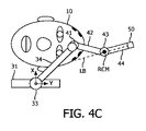
図4Cは、レーザビームLBを第2マーカ上に中心を合わせるためのピッチアクチュエータ41のサーボモジュール61aによるサーボ制御を示し、これによれば、サーボモジュール61a又は位置合わせモジュール62aは第2マーカ上でのレーザビームLBの中心合わせに対応してピッチアクチュエータ41及びヨーアクチュエータ43のコード化位置を記録する。
FIG. 4C shows the servo control by the
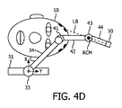
図4Dは、レーザビームLBを第3マーカ上に中心を合わせるためのピッチアクチュエータ41及びヨーアクチュエータ43のサーボモジュール61aによるサーボ制御を示し、これによれば、サーボモジュール61a又は位置合わせモジュール62aは第3マーカ上でのレーザビームLBの中心合わせに対応してピッチアクチュエータ41及びヨーアクチュエータ43のコード化位置を記録する。
FIG. 4D shows the servo control by the
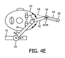
そして、図4Eは、レーザビームLBを第4マーカ上に中心を合わせるためのピッチアクチュエータ41のサーボモジュール61aによるサーボ制御を示し、これによれば、サーボモジュール61a又は位置合わせモジュール62aは第4マーカ上でのレーザビームLBの中心合わせに対応してピッチアクチュエータ41及びヨーアクチュエータ43のコード化位置を記録する。
Then, FIG. 4E shows the servo control by the
ステージS108の完了に続いて、フローチャート100のステージS110は、位置合わせモジュール62aがピッチアクチュエータ41及びヨーアクチュエータ43の記録されたコード化位置を既知のように処理して、同心弧ロボット40をボリューム画像21に示されたマーカ及び計画された切開位置に位置合わせする過程を含む。
Following the completion of stage S108, in stage S110 of the flowchart 100, the
ステージS110の位置合わせに基づいて、ロボットプラットフォーム30のコード化されていない受動型又は能動型実施態様(“URP”)の場合、フローチャート100のステージS112は、図4Fに記号的に黒点で例示的に示された計画された切開位置にレーザビームLBの中心を合わせるために要する、ピッチアクチュエータ41及び/又はヨーアクチュエータ43のサーボモジュール61aを介しての自動サーボ制御を含む。
In the unencoded passive or active embodiment (“URP”) of the
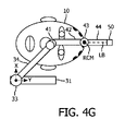
ステージS110の完了に続いて、フローチャート80のステージS92は手術医がステージS112の間にレーザビームLBにより示された患者の頭部の切開位置をマークする過程を含み、フローチャート80のステージS94は手術医が受動型ロボットプラットフォーム30を手動で操作するか又は能動型ロボットプラットフォーム30のためのサーボモジュール61aと遣り取りして、図4Gに例示的に示されるようにフローチャート100のステージS114の間に遠隔運動中心RCMを上記切開マーカに合わせる過程を含む。位置合わせモジュール62aは、当該位置合わせのグラフィック的及び/又はテキスト的確認情報を提供する。
Following the completion of stage S110, stage S92 of flowchart 80 includes the process of the surgeon marking the incision position of the patient's head indicated by the laser beam LB during stage S112, stage S94 of flowchart 80 is surgery. The physician manually operates the
ステージS94及びS114の完了に続いて、フローチャート80のステージS96は、手術医がサーボモジュール61aと遣り取りして、切開マーカを含む各マーカ上にレーザポインタ50のレーザビームLBを順次中心合わせする過程を含み、これによれば、フローチャート100のステージS114はサーボモジュール61a又は位置合わせモジュール62aが各マーカ上でのレーザビームLBの中心合わせに関してピッチアクチュエータ41及びヨーアクチュエータ43のコード化位置を記録する過程を含む。図4B〜図4Eは、患者10の頭部から隔てられるものとは異なるが、遠隔運動中心が切開マーカに合わされるステージS114の例示である。
Following the completion of stages S94 and S114, stage S96 of the flowchart 80 involves the surgeon interacting with the
各マーカ上でのレーザビームLBの中心合わせに続いて、フローチャート100のステージS118は、位置合わせモジュール62aがピッチアクチュエータ41及びヨーアクチュエータ43の記録されたコード化位置を既知のように処理して、遠隔運動中心RCMをボリューム画像21に示される切開マーカに位置合わせする過程を含む。ステージS118の位置合わせに基づいて、フローチャート100のステージS120は、図1に示された計画されたツール軌道TTにレーザビームLBを軸整列(軸合わせ)させるために要する、ピッチアクチュエータ41及び/又はヨーアクチュエータ43のサーボモジュール61aを介しての自動サーボ制御を含む。
Following the centering of the laser beam LB on each marker, the
ステージS110の位置合わせに基づいて、ロボットプラットフォーム30のコード化された受動型実施態様(“EPRP”)の場合、フローチャート80のステージS92は、ここでも、手術医がステージS112の間にレーザビームLBにより指示されるように患者の頭部上の切開位置をマークする過程を含み、フローチャート80のステージS94は、ここでも、手術医が受動型ロボットプラットフォーム30を手動で操作して、図4Gに例示的に示されるようにフローチャート100のステージS114の間に遠隔運動中心を上記切開マーカに合わせる過程を含む。位置合わせモジュール62aは、当該位置合わせのグラフィック的及び/又はテキスト的確認情報を提供する。
In the case of the coded passive embodiment (“EPRP”) of the
ステージS106のコード化追跡によれば、ステージS116及びS118による切開マーカに対する遠隔運動中心の位置合わせは、ステージS110の間にボリューム画像に示される切開点に対する遠隔運動中心RCMの値合わせに鑑みて、省略される。このように、ステージS114の確認情報を手術医が承認すると、サーボモジュール61aは、図1に示されるように計画されたツール軌道TTにレーザビームLBを軸整列させるために要するピッチアクチュエータ41及び/又はヨーアクチュエータ43のサーボモジュール61aを介しての自動サーボ制御のためにステージS114からステージS120に進む。
According to the coded tracking of stage S106, the alignment of the remote motion center with respect to the incision marker by stages S116 and S118 is in view of the value alignment of the remote motion center RCM with respect to the incision point shown in the volume image during stage S110. Omitted. As described above, when the surgeon approves the confirmation information of the stage S114, the
ステージS106のコード化追跡及びステージS110の位置合わせに基づいて、ロボットプラットフォーム30のコード化された能動型実施態様(“EARP”)の場合、ステージS114によるRCM位置合わせ並びにステージS116及びS118による切開マーカに対する遠隔運動中心RCMの位置合わせは、ステージS110の間においてボリューム画像内に示される切開点に対する遠隔運動中心RCMの位置合わせに鑑みて省略される。このように、ステージS106のプラットフォーム追跡及びステージS110の位置合わせに基づいて、サーボモジュール61aは、図1に示されるように計画されたツール軌道TTにレーザビームLBを軸整列させるために要するピッチアクチュエータ41及び/又はヨーアクチュエータ43のサーボモジュール61aを介しての自動サーボ制御のためにステージS110からステージS120に進む。
Based on the coded tracking of stage S106 and the alignment of stage S110, in the case of the coded active embodiment (“EARP”) of the
図1及び図2を依然として参照すると、フローチャート80及び100が完了した場合、当業者であれば、図1の生検フェーズを最小限のヒューマンエラーで正確且つ制御された態様で実行することができることが分かるであろう。 Still referring to FIGS. 1 and 2, one of ordinary skill in the art can perform the biopsy phase of FIG. 1 in an accurate and controlled manner with minimal human error when flowcharts 80 and 100 are completed. You will see.
図1を参照すると、実際には、前記位置合わせフェーズは、更に自動化することができ及び/又は種々の異なる光学エンドエフェクタを利用することができる。 With reference to FIG. 1, in practice, the alignment phase can be further automated and / or a variety of different optical end effectors can be utilized.
例えば、図5は、カメラ140を患者10の頭部に付着されたマーカ及びレーザポインタ50を視野内に置くような態様で動作空間内に組み込んだ(例えば、ロボットプラットフォーム30又は同心弧ロボット40に取り付けられた)本開示の例示的位置合わせフェーズを示す。サーボモジュール61bは、通信経路63bを介してカメラ140のコントローラと通信し、前述したようにマーカ上にレーザポインタ50のレーザビームLBの中心を合わせる際にロボット30のサーボ制御を自動的に実行するように構成される。このような制御は、図2に示されたステージS108及びステージS118(当てはまるなら)の間において手術医がサーボモジュール61bと遣り取りをする如何なる必要性も取り除く。
For example, FIG. 5 shows that the
また、例示として、図6はレーザポインタ50の代わりに内視鏡51を利用した本開示の例示的位置合わせフェーズを示す。この実施態様のために、サーボモジュール61cは、図2に示したようなステージS108及びステージS118(当てはまる場合)の間における該内視鏡51の視野内での各マーカの中心合わせを含む自動的サーボ制御を実行するように構成される。更に詳細には、図3A〜図3Dに各々示されるマーカ130〜133に対し、サーボモジュール61cは、図2に示されるようなステージS108及びステージS118(当てはまるなら)の間において内視鏡51の視野内でのマーカ130〜133の順次の中心合わせにおいて自動的サーボ制御を実行する。
Also, as an example, FIG. 6 shows an exemplary alignment phase of the present disclosure using an
実際のところ、図1の各コントローラは、単一のワークステーション内に設置し、又は複数のワークステーションにまたがって分散させることができる。 In fact, each controller in FIG. 1 can be installed within a single workstation or distributed across multiple workstations.
例えば、図7Aは、CT、MRI又はUS撮像のために設置された本開示の撮像コントローラ(例えば、撮像コントローラ20)を有する撮像ワークステーション150、並びに本開示のサーボモジュール及び位置合わせモジュールを実行するために設置された本開示のロボットコントローラ(例えば、ロボットコントローラ60)を有する手術ロボットワークステーション151を示している。
For example, FIG. 7A implements an
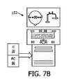
更なる例示として、図7Bは、CT、MRI又はUS撮像のために設置された本開示の撮像コントローラ(例えば、撮像コントローラ20)を有すると共に、本開示のサーボモジュール及び位置合わせモジュールを実行するために設置された本開示のロボットコントローラ(例えば、ロボットコントローラ60)を有するワークステーション152を示している。ワークステーション152の場合、各コントローラは物理的/論理的に分離し又は統合することができる。
As a further example, FIG. 7B has an imaging controller of the present disclosure (eg, imaging controller 20) installed for CT, MRI or US imaging and for executing the servo module and alignment module of the present disclosure. Shows a
また、実際のところ、本開示の位置合わせモジュールは、本開示のロボットコントローラと通信する本開示の撮像コントローラのアプリケーションとすることができる。 Also, in practice, the alignment module of the present disclosure can be an application of the imaging controller of the present disclosure that communicates with the robot controller of the present disclosure.
図1〜図7を参照した場合、当業者であれば、介入ツールを最小限のヒューマンエラーのリスクで正確且つ制御された態様で配置するための患者に対する遠隔運動中心ロボットの新規で固有な光学的位置合わせ(これに限るものではない)を含む、本開示の多数の利点を理解するであろう。 With reference to FIGS. 1-7, one of ordinary skill in the art would appreciate the novel and unique optics of a remote movement centered robot for a patient to place intervention tools in an accurate and controlled manner with minimal risk of human error. You will understand a number of advantages of the present disclosure, including, but not limited to, alignment.
更に、当業者であれば本明細書でなされる教示に鑑み理解するように、本開示/明細書に記載され及び/又は図1〜図7に示されたフィーチャ、エレメント、構成部品等は、電子部品/回路、ハードウェア、実行可能なソフトウェア及び実行可能なファームウエアの種々の組み合わせで実施化することができると共に、単一のエレメント又は複数のエレメント内で組み合わせることができる機能を提供することができる。例えば、図1〜図7に示され/図示され/描かれた種々のフィーチャ、エレメント、構成部品等の機能は、専用のハードウェア及び適切なソフトウェアとの関連でソフトウェアを実行することができるハードウェアの使用により提供することができる。プロセッサにより提供される場合、これら機能は単一の専用プロセッサにより、単一の共有プロセッサにより又は複数の個別のプロセッサにより提供され得るものであり、これらの幾つかは共有及び/又は多重化され得る。更に、“プロセッサ”なる用語の明示的な使用は、ソフトウェアを実行することができるハードウェアを専ら指すとみなされるべきではなく、限定無しで、デジタル信号プロセッサ(“DSP”)ハードウェア、メモリ(例えば、ソフトウェアを記憶するための読取専用メモリ(“ROM”)、ランダムアクセスメモリ(“RAM”)、不揮発性記憶部等)、並びに処理を実行及び/又は制御することができる(及び/又は処理を実行及び/又は制御するように構成することができる)実質的に任意の手段及び/又はマシン(ハードウェア、ソフトウェア、ファームウエア、回路、これらの組み合わせ等を含む)を暗黙的に含むことができる。 Further, as will be appreciated by those skilled in the art in light of the teachings made herein, the features, elements, components, etc. described in this disclosure / specification and / or shown in FIGS. To provide functions that can be implemented with various combinations of electronic components / circuits, hardware, executable software and executable firmware, as well as functions that can be combined within a single element or multiple elements. Can be done. For example, the functions of the various features, elements, components, etc. shown / illustrated / drawn in FIGS. 1-7 are hardware capable of running the software in the context of dedicated hardware and suitable software. It can be provided by the use of hardware. When provided by a processor, these features may be provided by a single dedicated processor, by a single shared processor, or by multiple individual processors, some of which may be shared and / or multiplexed. .. Moreover, the explicit use of the term "processor" should not be considered exclusively to the hardware capable of running the software, and without limitation, digital signal processor ("DSP") hardware, memory ( For example, read-only memory (“ROM”) for storing software, random access memory (“RAM”), non-volatile storage, etc.), and processing can be executed and / or controlled (and / or processing). Implicitly include virtually any means and / or machines (including hardware, software, firmware, circuits, combinations thereof, etc.) that can be configured to perform and / or control. it can.
更に、本発明の原理、態様及び実施態様並びにこれらの特定の例を引用する全ての記述は、これらの構造的等価物及び機能的等価物の両方を含もうとするものである。更に、このような均等物は現在知られている均等物及び将来開発される均等物(例えば、構造とは無関係に、同一又は実質的に同様の機能を果たし得る、開発された何らかのエレメント)の両方を含むものである。このように、例えば、当業者であれば本明細書でなされる教示に鑑みて、本明細書で提示される如何なるブロック図も、本発明の原理を具現化する解説的システム部品及び/又は回路の思想的見方を表すことができることが分かるであろう。同様に、当業者であれば本明細書でなされる教示に鑑み、如何なるフローチャート及び流れ図等も、コンピュータ読取可能な記憶媒体内で実質的に表すことができ、従ってコンピュータ、プロセッサ又は処理能力を備える他の装置により実行され得る(このようなコンピュータ又はプロセッサが明示的に示されているか否かによらず)種々の処理を表すことができると理解すべきである。 Moreover, all descriptions quoting the principles, embodiments and embodiments of the present invention and their particular examples are intended to include both structural and functional equivalents thereof. Moreover, such equivalents are of currently known equivalents and future developed equivalents (eg, any element developed that can perform the same or substantially similar function regardless of structure). It includes both. Thus, for example, any block diagram presented herein in view of the teachings made herein by one of ordinary skill in the art is an explanatory system component and / or circuit that embodies the principles of the present invention. You will find that it can express the ideological view of. Similarly, any flow chart, flow chart, etc., in view of the teachings made herein, can be substantially represented within a computer readable storage medium by those skilled in the art, and thus is equipped with a computer, processor or processing power. It should be understood that it can represent various processes that can be performed by other devices (whether or not such computers or processors are explicitly indicated).
更に、本開示の例示的実施態様は、例えばコンピュータ若しくは何らかの命令実行システムにより又は関連して使用するためのプログラムコード及び/又は命令を供給するコンピュータ使用可能な及び/又はコンピュータ読取可能な記憶媒体からアクセスすることができるコンピュータプログラム製品又はアプリケーションモジュールの形態をとることができる。本開示によれば、コンピュータ使用可能な又はコンピュータ読取可能な記憶媒体は、例えば命令実行システム、装置若しくはデバイスにより又は関連して使用するために当該プログラムを含み、記憶し、通知し、伝搬し又は伝送することができる任意の装置とすることができる。このような例示的媒体は、例えば、電子、磁気、光学、電磁、赤外若しくは半導体システム又は伝搬媒体とすることができる。コンピュータ読取可能な媒体の例は、例えば、半導体又は固体メモリ、磁気テープ、取り外し可能なコンピュータディスケット、ランダムアクセスメモリ(RAM)、読取専用メモリ(ROM)、フラッシュ(ドライブ)、剛性磁気ディスク及び光ディスクを含む。光ディスクの現在の例は、コンパクトディスク-読取専用メモリ(CD−ROM)、コンパクトディスク-読取/書込(CD−RW)及びDVDを含む。更に、今後開発され得る如何なる新たなコンピュータ読取可能な媒体も、本開示の例示的実施態様により使用され又は参照することができるコンピュータ読取可能な媒体と見なされるべきであると理解されたい。 Moreover, exemplary embodiments of the present disclosure are, for example, from a computer-enabled and / or computer-readable storage medium that supplies program code and / or instructions for use by or in connection with a computer or some instruction execution system. It can take the form of an accessible computer program product or application module. According to the present disclosure, a computer-usable or computer-readable storage medium includes, stores, notifies, propagates or propagates such a program for use, for example, by or in connection with an instruction execution system, device or device. It can be any device that can transmit. Such exemplary media can be, for example, electronic, magnetic, optical, electromagnetic, infrared or semiconductor systems or propagation media. Examples of computer-readable media include, for example, semiconductor or solid-state memory, magnetic tape, removable computer diskettes, random access memory (RAM), read-only memory (ROM), flash (drive), rigid magnetic disks and optical disks. Including. Current examples of optical discs include compact disc-read-only memory (CD-ROM), compact disc-read / write (CD-RW) and DVD. Further, it should be understood that any new computer-readable medium that may be developed in the future should be considered as a computer-readable medium that can be used or referenced according to the exemplary embodiments of the present disclosure.
患者に対する遠隔運動中心ロボットの新規且つ発明的光学位置合わせの好ましい及び例示的実施態様(解説的であることを意図し、限定するものではない)を説明したので、当業者によれば、図1〜図7を含む本明細書に提示された教示に照らして種々の修正及び変更を行うことができることに注意されたい。従って、本開示の好ましい及び例示的実施態様に対し、ここに開示された実施態様の範囲内である変更を行うことができると理解されるべきである。 As preferred and exemplary embodiments (intentionally, but not limited to, explanatory) of novel and invention optical alignment of remote motion center robots for patients have been described, one of ordinary skill in the art will appreciate FIG. It should be noted that various modifications and changes may be made in light of the teachings presented herein, including FIG. Therefore, it should be understood that changes can be made to the preferred and exemplary embodiments of the present disclosure that are within the scope of the embodiments disclosed herein.
更に、当該装置を組み込む及び/又は実施化する対応する及び/又は関連するシステム、又は本開示による装置で使用/実施化することができるような装置も、考えることができ、本開示の範囲内に入ると見なされることが想定される。更に、本開示による装置及び/又はシステムを製造及び/又は使用する対応する及び/又は関連する方法も、考えることができ、本開示の範囲内に入ると見なされる。 Further, corresponding and / or related systems incorporating and / or implementing such devices, or devices that can be used / implemented in the devices according to the present disclosure are also conceivable and within the scope of the present disclosure. It is expected to be considered to enter. In addition, corresponding and / or related methods of manufacturing and / or using the devices and / or systems according to the present disclosure are also conceivable and are considered to fall within the scope of the present disclosure.
Claims (15)
光学エンドエフェクタと、
RCMロボット自身の構造により定まる遠隔運動中心の回りで前記光学エンドエフェクタを回転させるRCMロボットと、
ロボットコントローラと、
を有し、
前記ロボットコントローラは、前記RCMロボットと通信して、該RCMロボットによる前記患者に付着された少なくとも1つのマーカに対する前記光学エンドエフェクタの光学的照準合わせを制御し、
前記ロボットコントローラは、更に、前記RCMロボットと通信して、該RCMロボットによる前記患者のボリューム画像内に示される前記計画されたツール軌道への前記光学エンドエフェクタの軸合わせを、前記RCMロボットによる前記患者に付着された前記少なくとも1つのマーカに対する前記光学エンドエフェクタの光学的照準合わせから導出された前記患者のボリューム画像内に示される前記計画された切開点への前記遠隔運動中心の位置合わせに基づいて制御する、
ロボット手術システム。 A robotic surgery system for minimally invasive procedures using a planned tool trajectory into a patient through a planned incision point.
Optical end effector and
And RCM robot makes rotating the optical end effector remotely center of movement around determined by the structure of the RCM robot itself,
With the robot controller
Have,
The robot controller communicates with the RCM robot to control the optical aiming of the optical end effector with respect to at least one marker attached to the patient by the RCM robot.
The robot controller further communicates with the RCM robot to align the optical end effector with the planned tool trajectory shown in the patient's volume image by the RCM robot. Based on the alignment of the remote center of motion to the planned incision point shown in the patient's volume image derived from the optical aiming of the optical end effector with respect to the at least one marker attached to the patient. Control
Robotic surgery system.
前記ロボットコントローラは、前記RCMロボット及び前記ロボットプラットフォームと通信して、該RCMロボット及びロボットプラットフォームにより前記患者に付着された前記少なくとも1つのマーカに対する前記光学エンドエフェクタの光学的照準合わせを制御し、
前記ロボットコントローラは、前記RCMロボット及び前記ロボットプラットフォームと通信して、該RCMロボット及びロボットプラットフォームによる前記患者のボリューム画像内に示される前記計画されたツール軌道への前記光学エンドエフェクタの軸合わせを、前記RCMロボットによる前記患者に付着された前記少なくとも1つのマーカに対する前記光学エンドエフェクタの光学的照準合わせから導出された前記患者のボリューム画像内に示される前記計画された切開点への前記遠隔運動中心の位置合わせに基づいて制御する、
請求項1に記載のロボット手術システム。 It further has a robot platform for positioning the RCM robot with respect to the patient.
The robot controller communicates with the RCM robot and the robot platform to control the optical aiming of the optical end effector with respect to the at least one marker attached to the patient by the RCM robot and the robot platform.
The robot controller communicates with the RCM robot and the robot platform to align the optical end effector with the planned tool trajectory shown in the volume image of the patient by the RCM robot and robot platform. The remote center of motion to the planned incision point shown in the patient's volume image derived from the optical aiming of the optical end effector with respect to the at least one marker attached to the patient by the RCM robot. Control based on the alignment of
The robotic surgery system according to claim 1.
前記ロボットコントローラは、前記RCMロボットと通信して、該RCMロボットによる前記患者に付着された前記少なくとも1つのマーカに対する前記レーザポインタによるレーザビームの放射の光学的照準合わせを制御し、
前記ロボットコントローラは、更に、前記RCMロボットと通信して、該RCMロボットによる前記患者のボリューム画像内に示される前記計画されたツール軌道への前記レーザポインタによるレーザビームの放射の軸合わせを、前記RCMロボットによる前記患者に付着された前記少なくとも1つのマーカに対する前記レーザポインタによるレーザビームの放射の光学的照準合わせから導出された前記患者のボリューム画像内に示される前記計画された切開点への前記遠隔運動中心の位置合わせに基づいて制御する、
請求項1に記載のロボット手術システム。 The optical end effector is a laser pointer that emits a laser beam.
The robot controller communicates with the RCM robot to control the optical aiming of the laser beam emission by the laser pointer with respect to the at least one marker attached to the patient by the RCM robot.
The robot controller further communicates with the RCM robot to align the emission of the laser beam by the laser pointer to the planned tool trajectory shown in the volume image of the patient by the RCM robot. The said to the planned incision point shown in the patient's volume image derived from the optical aiming of the laser beam emission by the laser pointer with respect to the at least one marker attached to the patient by an RCM robot. Control based on the alignment of the remote center of motion,
The robotic surgery system according to claim 1.
前記ロボットコントローラは、前記RCMロボットと通信して、該RCMロボットによる前記患者に付着された前記少なくとも1つのマーカに対する前記内視鏡の視野の光学的照準合わせを制御し、
前記ロボットコントローラは、更に、前記RCMロボットと通信して、該RCMロボットによる前記患者のボリューム画像内に示される前記計画されたツール軌道への前記内視鏡の視野の軸合わせを、前記RCMロボットによる前記患者に付着された前記少なくとも1つのマーカに対する前記内視鏡の視野の光学的照準合わせから導出された前記患者のボリューム画像内に示される前記計画された切開点への前記遠隔運動中心の位置合わせに基づいて制御する、
請求項1に記載のロボット手術システム。 The optical end effector is an endoscope having a field of view.
The robot controller communicates with the RCM robot to control the optical aiming of the endoscope's field of view with respect to the at least one marker attached to the patient by the RCM robot.
The robot controller further communicates with the RCM robot to align the field of view of the endoscope with the planned tool trajectory shown in the volume image of the patient by the RCM robot. Of the remote motion center to the planned incision point shown in the volume image of the patient derived from the optical aiming of the field of view of the endoscope with respect to the at least one marker attached to the patient. Control based on alignment,
The robotic surgery system according to claim 1.
前記ロボットコントローラが、前記RCMロボット及び前記カメラと通信して、前記RCMロボットによる前記患者に付着された前記少なくとも1つのマーカに対する前記光学エンドエフェクタの光学的照準合わせを制御する、
請求項1に記載のロボット手術システム。 It further comprises a camera that images the optical end effector in association with the at least one marker attached to the patient.
The robot controller communicates with the RCM robot and the camera to control the optical aiming of the optical end effector with respect to the at least one marker attached to the patient by the RCM robot.
The robotic surgery system according to claim 1.
RCMロボットが、光学エンドエフェクタを前記患者に付着された少なくとも1つのマーカに対し光学的に照準合わせするステップと、
位置合わせモジュールが、前記RCMロボットによる前記患者に付着された前記少なくとも1つのマーカに対する前記光学エンドエフェクタの光学的照準合わせから、前記患者のボリューム画像内に示される前記計画された切開点への遠隔運動中心の位置合わせを導き出すステップであって、前記遠隔運動中心が前記RCMロボットの構造により定まるステップと、
前記RCMロボットが、前記患者のボリューム画像内に示される前記計画されたツール軌道に対して前記光学エンドエフェクタを、前記位置合わせモジュールによる前記患者のボリューム画像内に示される前記計画された切開点に対する前記遠隔運動中心の位置合わせに基づいて軸合わせするステップと、
を有する、ロボット手術方法。 A robotic surgical method for minimally invasive procedures using a planned tool trajectory into a patient through a planned incision point.
A step in which the RCM robot optically aims the optical end effector at at least one marker attached to the patient.
The alignment module is remote from the optical aiming of the optical end effector to the at least one marker attached to the patient by the RCM robot to the planned incision point shown in the patient's volume image. A step of deriving the alignment of the movement center, the step in which the remote movement center is determined by the structure of the RCM robot, and the step.
The RCM robot places the optical end effector on the planned tool trajectory shown in the patient's volume image with respect to the planned incision point shown in the patient's volume image by the alignment module. The step of aligning the axis based on the alignment of the center of remote motion, and
A robotic surgery method that has.
前記ロボットコントローラは、前記光学エンドエフェクタを、前記患者のボリューム画像内に示されると共に前記光学エンドエフェクタにより撮像される前記少なくとも1つのマーカの一致に基づいて前記患者に付着された前記少なくとも1つのマーカに対し光学的に照準合わせするようサーボ制御する、
請求項9に記載のロボット手術方法。 The optical end effector images the at least one marker attached to the patient.
The robot controller attaches the optical end effector to the patient based on the coincidence of the at least one marker shown in the volume image of the patient and imaged by the optical end effector. Servo control to optically aim at
The robotic surgery method according to claim 9.
前記RCMロボットは、前記レーザポインタによるレーザビームの放射を前記患者に付着された前記少なくとも1つのマーカに対して光学的に照準合わせし、
前記位置合わせモジュールは、前記患者のボリューム画像内に示される前記計画された切開点への前記遠隔運動中心の位置合わせを、前記RCMロボットによる前記患者に付着された前記少なくとも1つのマーカに対する前記レーザポインタによるレーザビームの放射の光学的照準合わせから導き出し、
前記RCMロボットは、前記レーザポインタによるレーザビームの放射を、前記位置合わせモジュールによる前記患者のボリューム画像内に示される前記計画された切開点への前記遠隔運動中心の位置合わせに基づいて、前記患者のボリューム画像内に示される前記計画されたツール軌道に軸合わせする、
請求項7に記載のロボット手術方法。 The optical end effector is a laser pointer that emits a laser beam.
The RCM robot optically aims the emission of the laser beam from the laser pointer to the at least one marker attached to the patient.
The alignment module aligns the remote center of motion with respect to the planned incision point shown in the patient's volume image with the laser on the at least one marker attached to the patient by the RCM robot. Derived from the optical aiming of the laser beam emission by the pointer,
The RCM robot emits a laser beam from the laser pointer based on the alignment of the remote center of motion to the planned incision point shown in the volume image of the patient by the alignment module. Axis to the planned tool trajectory shown in the volume image of
The robotic surgery method according to claim 7.
前記RCMロボットは、前記内視鏡の視野を前記患者に付着された前記少なくとも1つのマーカに対して光学的に照準合わせし、
前記位置合わせモジュールは、前記患者のボリューム画像内に示される前記計画された切開点への前記遠隔運動中心の位置合わせを、前記RCMロボットによる前記患者に付着された前記少なくとも1つのマーカに対する前記内視鏡の視野の光学的照準合わせから導き出し、
前記RCMロボットは、前記内視鏡の視野を、前記位置合わせモジュールによる前記患者のボリューム画像内に示される前記計画された切開点への前記遠隔運動中心の位置合わせに基づいて、前記患者のボリューム画像内に示される前記計画されたツール軌道に軸合わせする、
請求項7に記載のロボット手術方法。 The optical end effector is an endoscope having a field of view.
The RCM robot optically aims the field of view of the endoscope with respect to the at least one marker attached to the patient.
The alignment module aligns the remote center of motion with respect to the planned incision point shown in the patient's volume image with respect to the at least one marker attached to the patient by the RCM robot. Derived from the optical aiming of the field of view of the endoscope,
The RCM robot aligns the field of view of the endoscope with the patient's volume to the planned incision point shown in the patient's volume image by the alignment module. Axis to the planned tool trajectory shown in the image,
The robotic surgery method according to claim 7.
前記RCMロボットが、前記光学エンドエフェクタを、前記カメラによる該光学エンドエフェクタの前記患者に付着された前記少なくとも1つのマーカとの相対的な撮像に基づいて、前記患者に付着された前記少なくとも1つのマーカに対し光学的に照準を合わせる、
請求項7に記載のロボット手術方法。 The camera further comprises the step of imaging the optical end effector in association with the at least one marker attached to the patient.
The RCM robot attaches the optical end effector to the patient based on the relative imaging of the optical end effector with the at least one marker attached to the patient by the camera. Optically aim at the marker,
The robotic surgery method according to claim 7.
Applications Claiming Priority (3)
| Application Number | Priority Date | Filing Date | Title |
|---|---|---|---|
| US201562233664P | 2015-09-28 | 2015-09-28 | |
| US62/233,664 | 2015-09-28 | ||
| PCT/IB2016/055743 WO2017055990A1 (en) | 2015-09-28 | 2016-09-26 | Optical registration of a remote center of motion robot |
Publications (3)
| Publication Number | Publication Date |
|---|---|
| JP2018530383A JP2018530383A (en) | 2018-10-18 |
| JP2018530383A5 JP2018530383A5 (en) | 2019-11-07 |
| JP6865739B2 true JP6865739B2 (en) | 2021-04-28 |
Family
ID=57130415
Family Applications (1)
| Application Number | Title | Priority Date | Filing Date |
|---|---|---|---|
| JP2018515500A Active JP6865739B2 (en) | 2015-09-28 | 2016-09-26 | Optical alignment of remote motion center robot |
Country Status (5)
| Country | Link |
|---|---|
| US (1) | US20200246085A1 (en) |
| EP (1) | EP3355822A1 (en) |
| JP (1) | JP6865739B2 (en) |
| CN (1) | CN108348299B (en) |
| WO (1) | WO2017055990A1 (en) |
Families Citing this family (5)
| Publication number | Priority date | Publication date | Assignee | Title |
|---|---|---|---|---|
| US11564757B2 (en) * | 2017-02-27 | 2023-01-31 | The Regents Of The University Of California | Laser-assisted surgical alignment |
| US11789099B2 (en) * | 2018-08-20 | 2023-10-17 | Children's Hospital Medical Center | System and method for guiding an invasive device |
| JP2023505164A (en) * | 2019-12-02 | 2023-02-08 | シンク サージカル, インコーポレイテッド | Systems and methods for aligning tools with axes to perform medical procedures |
| CN113180828B (en) * | 2021-03-25 | 2023-05-12 | 北京航空航天大学 | Surgical robot constraint motion control method based on rotation theory |
| DE102021133060A1 (en) * | 2021-12-14 | 2023-06-15 | B. Braun New Ventures GmbH | Robotic surgical system and control method |
Family Cites Families (18)
| Publication number | Priority date | Publication date | Assignee | Title |
|---|---|---|---|---|
| JP2551582Y2 (en) * | 1990-02-27 | 1997-10-22 | 株式会社島津製作所 | Medical guide needle insertion instruction device |
| CN101043843A (en) * | 2004-06-30 | 2007-09-26 | 詹姆士·V·西茨曼 | Medical devices for minimally invasive surgeries and other internal procedures |
| US8971597B2 (en) * | 2005-05-16 | 2015-03-03 | Intuitive Surgical Operations, Inc. | Efficient vision and kinematic data fusion for robotic surgical instruments and other applications |
| US8265731B2 (en) * | 2007-02-13 | 2012-09-11 | Siemens Medical Solutions Usa, Inc. | Apparatus and method for aligning a light pointer with a medical interventional device trajectory |
| US9370627B2 (en) * | 2007-02-20 | 2016-06-21 | Siemens Medical Solutions Usa, Inc. | Needle guidance with a dual-headed laser |
| FR2917598B1 (en) * | 2007-06-19 | 2010-04-02 | Medtech | MULTI-APPLICATIVE ROBOTIC PLATFORM FOR NEUROSURGERY AND METHOD OF RECALING |
| US20090281452A1 (en) * | 2008-05-02 | 2009-11-12 | Marcus Pfister | System and method for a medical procedure using computed tomography |
| US8414469B2 (en) * | 2008-06-27 | 2013-04-09 | Intuitive Surgical Operations, Inc. | Medical robotic system having entry guide controller with instrument tip velocity limiting |
| WO2011088400A2 (en) * | 2010-01-14 | 2011-07-21 | The Regents Of The University Of California | Apparatus, system, and method for robotic microsurgery |
| US8670017B2 (en) * | 2010-03-04 | 2014-03-11 | Intouch Technologies, Inc. | Remote presence system including a cart that supports a robot face and an overhead camera |
| WO2012033552A1 (en) * | 2010-09-10 | 2012-03-15 | The Johns Hopkins University | Visualization of registered subsurface anatomy reference to related applications |
| EP2636034A4 (en) * | 2010-11-04 | 2015-07-22 | Univ Johns Hopkins | System and method for the evaluation of or improvement of minimally invasive surgery skills |
| US20140039314A1 (en) * | 2010-11-11 | 2014-02-06 | The Johns Hopkins University | Remote Center of Motion Robot for Medical Image Scanning and Image-Guided Targeting |
| US20120226145A1 (en) * | 2011-03-03 | 2012-09-06 | National University Of Singapore | Transcutaneous robot-assisted ablation-device insertion navigation system |
| US11013480B2 (en) * | 2012-06-28 | 2021-05-25 | Koninklijke Philips N.V. | C-arm trajectory planning for optimal image acquisition in endoscopic surgery |
| BR112015001895A2 (en) * | 2012-08-02 | 2017-07-04 | Koninklijke Philips Nv | robotic surgical system, and robotic method |
| DE102013213727A1 (en) * | 2013-07-12 | 2015-01-15 | Siemens Aktiengesellschaft | Interventional imaging system |
| CN113616334A (en) * | 2014-02-04 | 2021-11-09 | 皇家飞利浦有限公司 | Remote center of motion definition using light sources for robotic systems |
-
2016
- 2016-09-26 WO PCT/IB2016/055743 patent/WO2017055990A1/en active Application Filing
- 2016-09-26 JP JP2018515500A patent/JP6865739B2/en active Active
- 2016-09-26 CN CN201680066685.7A patent/CN108348299B/en not_active Expired - Fee Related
- 2016-09-26 US US15/762,757 patent/US20200246085A1/en not_active Abandoned
- 2016-09-26 EP EP16781202.3A patent/EP3355822A1/en not_active Withdrawn
Also Published As
| Publication number | Publication date |
|---|---|
| CN108348299B (en) | 2021-11-02 |
| WO2017055990A1 (en) | 2017-04-06 |
| EP3355822A1 (en) | 2018-08-08 |
| CN108348299A (en) | 2018-07-31 |
| US20200246085A1 (en) | 2020-08-06 |
| JP2018530383A (en) | 2018-10-18 |
Similar Documents
| Publication | Publication Date | Title |
|---|---|---|
| JP6865739B2 (en) | Optical alignment of remote motion center robot | |
| US11813030B2 (en) | Robotic navigation of robotic surgical systems | |
| US11896318B2 (en) | Methods and systems for controlling a surgical robot | |
| US9066737B2 (en) | Method for moving an instrument arm of a laparoscopy robot into a predeterminable relative position with respect to a trocar | |
| US11950858B2 (en) | Systems for performing computer assisted surgery | |
| CN114711969B (en) | Surgical robot system and application method thereof | |
| JP6968150B2 (en) | Tracking powered drill assembly | |
| US11416995B2 (en) | Systems, devices, and methods for contactless patient registration for a medical procedure | |
| US9914211B2 (en) | Hand-guided automated positioning device controller | |
| JP2020096829A (en) | Drill guide fixtures, cranial insertion fixtures, and related methods and robotic systems | |
| US20200030991A1 (en) | End effector force sensor and manual actuation assistance | |
| CN112839608A (en) | Multifunctional multi-arm robot operation system | |
| JP6970154B2 (en) | Surgical robot automation with tracking markers | |
| EP3586784B1 (en) | Methods of adjusting a virtual implant and related surgical navigation systems | |
| US20190175293A1 (en) | Image guidance for a decoupled kinematic control of a remote-center-of-motion | |
| CN114521965A (en) | Surgical instrument replacement robot, surgical robot system, and surgical instrument replacement system | |
| Yang et al. | Design and development of an augmented reality robotic system for large tumor ablation | |
| WO2023152561A1 (en) | Mobile system for bilateral robotic tool feeding | |
| Yu et al. | A framework for GPU-accelerated virtual cardiac intervention | |
| Seung et al. | Image-guided positioning robot for single-port brain surgery robotic manipulator | |
| Faria et al. | Review of robotic technology for keyhole transcranial stereotactic neurosurgery |
Legal Events
| Date | Code | Title | Description |
|---|---|---|---|
| A521 | Request for written amendment filed |
Free format text: JAPANESE INTERMEDIATE CODE: A523 Effective date: 20190925 |
|
| A621 | Written request for application examination |
Free format text: JAPANESE INTERMEDIATE CODE: A621 Effective date: 20190925 |
|
| A977 | Report on retrieval |
Free format text: JAPANESE INTERMEDIATE CODE: A971007 Effective date: 20200929 |
|
| A131 | Notification of reasons for refusal |
Free format text: JAPANESE INTERMEDIATE CODE: A131 Effective date: 20201020 |
|
| TRDD | Decision of grant or rejection written | ||
| A01 | Written decision to grant a patent or to grant a registration (utility model) |
Free format text: JAPANESE INTERMEDIATE CODE: A01 Effective date: 20210308 |
|
| A61 | First payment of annual fees (during grant procedure) |
Free format text: JAPANESE INTERMEDIATE CODE: A61 Effective date: 20210406 |
|
| R150 | Certificate of patent or registration of utility model |
Ref document number: 6865739 Country of ref document: JP Free format text: JAPANESE INTERMEDIATE CODE: R150 |