JP6864863B2 - Power storage element and manufacturing method of power storage element - Google Patents
Power storage element and manufacturing method of power storage element Download PDFInfo
- Publication number
- JP6864863B2 JP6864863B2 JP2016254056A JP2016254056A JP6864863B2 JP 6864863 B2 JP6864863 B2 JP 6864863B2 JP 2016254056 A JP2016254056 A JP 2016254056A JP 2016254056 A JP2016254056 A JP 2016254056A JP 6864863 B2 JP6864863 B2 JP 6864863B2
- Authority
- JP
- Japan
- Prior art keywords
- electrode body
- case
- current collector
- insulating member
- convex
- Prior art date
- Legal status (The legal status is an assumption and is not a legal conclusion. Google has not performed a legal analysis and makes no representation as to the accuracy of the status listed.)
- Active
Links
Images


Classifications
-
- Y—GENERAL TAGGING OF NEW TECHNOLOGICAL DEVELOPMENTS; GENERAL TAGGING OF CROSS-SECTIONAL TECHNOLOGIES SPANNING OVER SEVERAL SECTIONS OF THE IPC; TECHNICAL SUBJECTS COVERED BY FORMER USPC CROSS-REFERENCE ART COLLECTIONS [XRACs] AND DIGESTS
- Y02—TECHNOLOGIES OR APPLICATIONS FOR MITIGATION OR ADAPTATION AGAINST CLIMATE CHANGE
- Y02E—REDUCTION OF GREENHOUSE GAS [GHG] EMISSIONS, RELATED TO ENERGY GENERATION, TRANSMISSION OR DISTRIBUTION
- Y02E60/00—Enabling technologies; Technologies with a potential or indirect contribution to GHG emissions mitigation
- Y02E60/10—Energy storage using batteries
-
- Y—GENERAL TAGGING OF NEW TECHNOLOGICAL DEVELOPMENTS; GENERAL TAGGING OF CROSS-SECTIONAL TECHNOLOGIES SPANNING OVER SEVERAL SECTIONS OF THE IPC; TECHNICAL SUBJECTS COVERED BY FORMER USPC CROSS-REFERENCE ART COLLECTIONS [XRACs] AND DIGESTS
- Y02—TECHNOLOGIES OR APPLICATIONS FOR MITIGATION OR ADAPTATION AGAINST CLIMATE CHANGE
- Y02E—REDUCTION OF GREENHOUSE GAS [GHG] EMISSIONS, RELATED TO ENERGY GENERATION, TRANSMISSION OR DISTRIBUTION
- Y02E60/00—Enabling technologies; Technologies with a potential or indirect contribution to GHG emissions mitigation
- Y02E60/13—Energy storage using capacitors
Description
本発明は、ケースの内部で電極体と集電体とが絶縁部材に覆われている蓄電素子、及びこの蓄電素子の製造方法に関する。 The present invention relates to a power storage element in which an electrode body and a current collector are covered with an insulating member inside a case, and a method for manufacturing the power storage element.
従来から、電池缶の内部で捲回電極群と集電板とが絶縁シートに覆われた二次電池が知られている(特許文献1参照)。この二次電池では、捲回電極群が絶縁シートによって、その周囲を覆われることで電池缶に直接触れないように絶縁されている。 Conventionally, a secondary battery in which a winding electrode group and a current collector plate are covered with an insulating sheet inside a battery can has been known (see Patent Document 1). In this secondary battery, the winding electrode group is covered with an insulating sheet so as not to come into direct contact with the battery can.
具体的に、二次電池では、絶縁シートは、捲回電極群の合剤層積層領域と電池缶との間、及び、集電板と電池缶との間の一部に介在する部位を有する第一の絶縁シートと、捲回電極群の金属箔露出部と電池缶との間、及び、集電板と電池缶との間に介在する部位を有する第二の絶縁シートと、を有している。 Specifically, in the secondary battery, the insulating sheet has a portion interposed between the mixture layer laminated region of the wound electrode group and the battery can, and a part between the current collector plate and the battery can. It has a first insulating sheet and a second insulating sheet having a portion interposed between the exposed metal foil portion of the wound electrode group and the battery can, and between the current collector plate and the battery can. ing.
第一の絶縁シートは、一枚の矩形のシート部材を二つに折り畳むようにして、捲回電極群に被せることにより、捲回電極群の捲回軸方向の両側の端部間にわたって覆うように構成されている。第二の絶縁シートは、金属箔露出部を覆う断面コ字状の立体形状を有し、捲回電極群に取り付けることによって、第一の絶縁シートを捲回電極群に押さえ付けている。 The first insulating sheet is made by folding one rectangular sheet member in two and covering it with the winding electrode group so as to cover between the ends on both sides of the winding electrode group in the winding axis direction. It is configured in. The second insulating sheet has a three-dimensional shape having a U-shaped cross section that covers the exposed metal foil portion, and is attached to the wound electrode group to press the first insulating sheet against the wound electrode group.
上記の二次電池において、絶縁シート(第一の絶縁シート、第二の絶縁シート)は、捲回電極群を単に覆っているだけである。 In the above secondary battery, the insulating sheet (first insulating sheet, second insulating sheet) merely covers the wound electrode group.
電極体に対して絶縁部材がずれやすい。本実施形態は、絶縁部材が電極体に対してずれ難い蓄電素子及びこの蓄電素子の製造方法を提供することを目的とする。 The insulating member is easily displaced with respect to the electrode body. An object of the present embodiment is to provide a power storage element in which the insulating member does not easily shift with respect to the electrode body, and a method for manufacturing the power storage element.
上記のように、絶縁部材が電極体を単に覆っているだけでは、電極体に対して絶縁部材がずれやすいが、絶縁部材として電極体及び集電体を覆う大きさのものが使用された場合、蓄電素子に振動が加わっても、絶縁部材が電極体に対して大きくずれる前に他の部材に衝突することでそれ以上のずれが生じないため、ケース内での絶縁部材の電極体に対する位置ずれが問題となって短絡が生じることは大きな問題となっていなかった。このため、電極体や集電体の全体を覆う絶縁部材を、電極体や集電体に固定する必要があるという認識は電池業界にはほとんど無かった。 As described above, if the insulating member simply covers the electrode body, the insulating member is likely to be displaced from the electrode body, but when a member having a size that covers the electrode body and the current collector is used as the insulating member. Even if vibration is applied to the power storage element, the insulating member collides with other members before the insulating member is significantly displaced from the electrode body, so that no further displacement occurs. Therefore, the position of the insulating member with respect to the electrode body in the case. The problem of misalignment and the occurrence of short circuits was not a major problem. For this reason, there was almost no recognition in the battery industry that it was necessary to fix the insulating member covering the entire electrode body or current collector to the electrode body or current collector.
しかし、本発明の発明者らは、鋭意研究を行った結果、蓄電素子が衝撃によって破損してケースの蓋板が外れた場合や、蓄電素子の材料をリサイクルするために解体作業で電極体をケースから取り出す場合などに、絶縁部材が電極体や集電体に対してずれることに起因するケースを通じての短絡が実使用上問題となる程度に発生しうることを見出した。そこで、発明者らは、この知見に着目することによって以下の構成の蓄電素子等を創作し、これにより、上記課題を解消した。 However, as a result of diligent research, the inventors of the present invention disassembled the electrode body in order to recycle the material of the power storage element or when the power storage element is damaged by an impact and the lid plate of the case is removed. It has been found that a short circuit through the case due to the insulating member being displaced with respect to the electrode body or the current collector may occur to the extent that it becomes a problem in actual use when it is taken out from the case. Therefore, the inventors have created a power storage element or the like having the following configuration by paying attention to this finding, thereby solving the above-mentioned problems.
本発明の一実施形態に係る蓄電素子は、
ケースと、
前記ケースの内部に配置される電極体と、
前記電極体と前記ケースの外側に配置される外部端子又は前記ケースの少なくとも一部によって構成される外部端子とを繋ぐ集電体と、
前記ケースの内部で前記電極体及び前記集電体を覆う絶縁部材と、を備え、
前記集電体及び前記絶縁部材は、互いに凹凸嵌合している。
The power storage element according to an embodiment of the present invention is
With the case
The electrode body arranged inside the case and
A current collector that connects the electrode body with an external terminal arranged outside the case or an external terminal composed of at least a part of the case.
An insulating member that covers the electrode body and the current collector inside the case is provided.
The current collector and the insulating member are unevenly fitted to each other.
かかる構成によれば、集電体と絶縁部材とが互いに凹凸嵌合しているため、電極体とこれに接続された集電体とに対する嵌合方向と直交する方向への絶縁部材のずれが抑えられる。これにより、例えば、蓄電素子の材料をリサイクルするために解体作業で電極体をケースから取り出す場合などに、絶縁部材が電極体及び集電体に対してずれることに起因するケースを通じての短絡の発生を抑制することができる。 According to this configuration, since the current collector and the insulating member are unevenly fitted to each other, the insulating member is displaced in a direction orthogonal to the fitting direction between the electrode body and the current collector connected to the electrode body. It can be suppressed. As a result, for example, when the electrode body is taken out from the case in the dismantling work to recycle the material of the power storage element, a short circuit occurs through the case due to the insulating member being displaced with respect to the electrode body and the current collector. Can be suppressed.
前記蓄電素子では、
前記集電体は、前記電極体に接続される接続部を有し、
前記接続部は、前記電極体と対向する第一凹部及び該第一凹部に対して表裏の関係にある第二凸部、又は前記電極体と対向する第一凸部及び該第一凸部に対して表裏の関係にある第二凹部、を有し、
前記接続部の前記第一凹部又は前記第一凸部が前記電極体と凹凸嵌合すると共に、前記接続部の前記第二凸部又は前記第二凹部が前記絶縁部材と凹凸嵌合してもよい。
In the power storage element,
The current collector has a connecting portion connected to the electrode body, and has a connecting portion.
The connecting portion is formed on a first concave portion facing the electrode body and a second convex portion having a front-back relationship with the first concave portion, or a first convex portion facing the electrode body and the first convex portion. On the other hand, it has a second recess, which is in a front-to-back relationship.
Even if the first concave portion or the first convex portion of the connecting portion is unevenly fitted with the electrode body, and the second convex portion or the second concave portion of the connecting portion is unevenly fitted with the insulating member. Good.
かかる構成によれば、接続部の表裏における同じ位置(表裏の関係にある位置)において電極体と絶縁部材とがそれぞれ接続部に対して凹凸嵌合しているため、接続部と電極体とが凹凸嵌合する部位と、接続部と絶縁部材とが凹凸嵌合する部位とを別々に形成することなく、電極体と集電体とに対する嵌合方向と直交する方向への絶縁部材の相対移動を抑えることができる。 According to such a configuration, since the electrode body and the insulating member are unevenly fitted to the connecting portion at the same position on the front and back of the connecting portion (positions having a front and back relationship), the connecting portion and the electrode body are formed. Relative movement of the insulating member in a direction orthogonal to the fitting direction with respect to the electrode body and the current collector without separately forming the portion where the concave-convex fitting portion and the portion where the connecting portion and the insulating member are unevenly fitted are formed separately. Can be suppressed.
また、前記蓄電素子では、
前記電極体は、活物質層が配置されている本体と、前記本体と隣接し且つ前記集電体の前記接続部が接続される被接続部と、を有し、
前記絶縁部材と前記接続部と前記電極体とが凹凸嵌合している嵌合部位は、前記被接続部から前記本体に向かう方向から見て前記本体の内側に位置してもよい。
Further, in the power storage element,
The electrode body has a main body in which an active material layer is arranged, and a connected portion adjacent to the main body and to which the connecting portion of the current collector is connected.
The fitting portion where the insulating member, the connecting portion, and the electrode body are unevenly fitted may be located inside the main body when viewed from the direction from the connected portion toward the main body.
このように、被接続部から本体に向かう方向(所定方向)から見て嵌合部位(絶縁部材と接続部と電極体とが凹凸嵌合している部位)が本体の内側に位置しているため、前記所定方向と直交する方向においてケースを電極体の本体に近接させて配置するときに、嵌合部位が邪魔をしない。 In this way, the fitting portion (the portion where the insulating member, the connecting portion, and the electrode body are unevenly fitted) is located inside the main body when viewed from the direction (predetermined direction) from the connected portion to the main body. Therefore, when the case is arranged close to the main body of the electrode body in the direction orthogonal to the predetermined direction, the fitting portion does not interfere.
また、前記蓄電素子では、
前記絶縁部材は、前記第二凸部が嵌り込む絶縁凹部、又は前記第二凹部に嵌り込む絶縁凸部を有し、
前記絶縁凹部又は前記絶縁凸部は、前記第二凸部又は前記第二凹部に沿っていてもよい。
Further, in the power storage element,
The insulating member has an insulating concave portion into which the second convex portion is fitted, or an insulating convex portion into which the second convex portion is fitted.
The insulating concave portion or the insulating convex portion may be along the second convex portion or the second concave portion.
かかる構成によれば、第二凸部又は第二凹部に絶縁凹部又は絶縁凸部が密接した状態で絶縁部材と集電体の接続部とが凹凸嵌合するため、嵌合方向と直交する方向において凹凸嵌合している部位同士がよりずれ難く(相対移動し難く)なる。 According to this configuration, the insulating member and the connecting portion of the current collector are unevenly fitted with the insulating concave portion or the insulating convex portion in close contact with the second convex portion or the second concave portion, so that the direction is orthogonal to the fitting direction. In the case, the parts that are unevenly fitted to each other are more difficult to shift (relatively difficult to move).
また、本発明の他の実施形態に係る蓄電素子は、
ケースと、
前記ケースの内部に配置される電極体と、
前記ケースの内部で前記電極体を覆う絶縁部材と、を備え、
前記電極体及び前記絶縁部材は、互いに凹凸嵌合している。
Further, the power storage element according to another embodiment of the present invention is
With the case
The electrode body arranged inside the case and
An insulating member that covers the electrode body inside the case is provided.
The electrode body and the insulating member are unevenly fitted to each other.
かかる構成によれば、電極体と絶縁部材とが互いに凹凸嵌合しているため、電極体に対する嵌合方向と直交する方向への絶縁部材のずれが抑えられる。これにより、例えば、蓄電素子の材料をリサイクルするために解体作業で電極体をケースから取り出す場合などに、絶縁部材が電極体に対してずれることに起因するケースを通じた短絡の発生を抑制することができる。 According to such a configuration, since the electrode body and the insulating member are unevenly fitted to each other, the displacement of the insulating member in the direction orthogonal to the fitting direction with respect to the electrode body can be suppressed. As a result, for example, when the electrode body is taken out from the case in the dismantling work for recycling the material of the power storage element, the occurrence of a short circuit through the case due to the insulating member being displaced with respect to the electrode body can be suppressed. Can be done.
また、本発明の他の実施形態に係る蓄電素子の製造方法は、
ケースの内部に配置される電極体と前記ケースの外側に配置される外部端子又は前記ケースの少なくとも一部によって構成される外部端子とを繋ぐ集電体と、前記ケースの内部で前記電極体及び前記集電体を覆う絶縁部材と、を凹凸嵌合させること、を備える。
Further, the method for manufacturing a power storage element according to another embodiment of the present invention is described.
A current collector that connects an electrode body arranged inside the case and an external terminal arranged outside the case or an external terminal composed of at least a part of the case, and the electrode body and the electrode body inside the case. The insulating member covering the current collector and the insulating member are fitted in a concave-convex manner.
かかる構成によれば、製造された蓄電素子において、集電体と絶縁部材とが互いに凹凸嵌合しているため、電極体とこれに接続された集電体とに対する嵌合方向と直交する方向への絶縁部材のずれが抑えられる。これにより、上記製造方法によって製造された蓄電素子において、例えば、蓄電素子の材料をリサイクルするために解体作業で電極体をケースから取り出す場合などに、絶縁部材が電極体及び集電体に対してずれることに起因するケースを通じた短絡の発生が抑制される。 According to this configuration, in the manufactured power storage element, the current collector and the insulating member are unevenly fitted to each other, so that the direction is orthogonal to the fitting direction of the electrode body and the current collector connected to the electrode body. The displacement of the insulating member to is suppressed. As a result, in the power storage element manufactured by the above manufacturing method, for example, when the electrode body is taken out from the case in the dismantling work in order to recycle the material of the power storage element, the insulating member is attached to the electrode body and the current collector. The occurrence of short circuit through the case due to the deviation is suppressed.
また、前記蓄電素子の製造方法では、
前記凹凸嵌合は、前記電極体と前記集電体と前記絶縁部材とが重なっている部位を重ね方向に加圧するカシメ接合によって行ってもよい。
Further, in the method for manufacturing the power storage element, the method
The uneven fitting may be performed by caulking joining in which the portion where the electrode body, the current collector, and the insulating member overlap is pressed in the overlapping direction.
かかる構成によれば、カシメ接合の際に集電体と絶縁部材との間における前記凹凸嵌合する部位において金属粉等が発生したとしても、集電体が絶縁部材に覆われているため金属粉等が集電体と絶縁部材との間に閉じ込められ、これにより、前記金属粉等が他の部位に飛散等することを抑制することができる。 According to this configuration, even if metal powder or the like is generated at the uneven fitting portion between the current collector and the insulating member during caulking, the current collector is covered with the insulating member, so that the metal is used. The powder or the like is confined between the current collector and the insulating member, whereby it is possible to prevent the metal powder or the like from scattering to other parts.
また、本発明の他の実施形態に係る蓄電素子の製造方法は、
ケースの内部に配置される電極体と、前記ケースの内部で前記電極体を覆う絶縁部材と、を凹凸嵌合させること、を備える。
Further, the method for manufacturing a power storage element according to another embodiment of the present invention is described.
The electrode body arranged inside the case and the insulating member covering the electrode body inside the case are unevenly fitted.
かかる構成によれば、製造された蓄電素子において、電極体と絶縁部材とが互いに凹凸嵌合しているため、電極体に対する嵌合方向と直交する方向への絶縁部材のずれが抑えられる。これにより、上記製造方法によって製造された蓄電素子において、例えば、蓄電素子の材料をリサイクルするために解体作業で電極体をケースから取り出す場合などに、絶縁部材が電極体に対してずれることに起因するケースを通じた短絡の発生が抑制される。 According to such a configuration, in the manufactured power storage element, since the electrode body and the insulating member are unevenly fitted to each other, the displacement of the insulating member in the direction orthogonal to the fitting direction with respect to the electrode body can be suppressed. As a result, in the power storage element manufactured by the above manufacturing method, for example, when the electrode body is taken out from the case in the dismantling work in order to recycle the material of the power storage element, the insulating member is displaced with respect to the electrode body. The occurrence of a short circuit through the case is suppressed.
以上より、本実施形態によれば、絶縁部材が電極体に対してずれ難い蓄電素子及びこの蓄電素子の製造方法を提供することができる。 From the above, according to the present embodiment, it is possible to provide a power storage element in which the insulating member does not easily shift with respect to the electrode body, and a method for manufacturing the power storage element.
以下、本発明に係る蓄電素子の一実施形態について、図1〜図11を参照しつつ説明する。蓄電素子には、一次電池、二次電池、キャパシタ等がある。本実施形態では、蓄電素子の一例として、充放電可能な二次電池について説明する。尚、本実施形態の各構成部材(各構成要素)の名称は、本実施形態におけるものであり、背景技術における各構成部材(各構成要素)の名称と異なる場合がある。 Hereinafter, an embodiment of the power storage element according to the present invention will be described with reference to FIGS. 1 to 11. The power storage element includes a primary battery, a secondary battery, a capacitor, and the like. In the present embodiment, a rechargeable secondary battery will be described as an example of the power storage element. The name of each component (each component) of the present embodiment is that of the present embodiment, and may be different from the name of each component (each component) in the background technology.
本実施形態の蓄電素子は、非水電解質二次電池である。より詳しくは、蓄電素子は、リチウムイオンの移動に伴って生じる電子移動を利用したリチウムイオン二次電池である。この種の蓄電素子は、電気エネルギーを供給する。蓄電素子は、単一又は複数で使用される。具体的に、蓄電素子は、要求される出力及び要求される電圧が小さいときには、単一で使用される。一方、蓄電素子は、要求される出力及び要求される電圧の少なくとも一方が大きいときには、他の蓄電素子と組み合わされて蓄電装置に用いられる。この蓄電装置では、該蓄電装置に用いられる蓄電素子が電気エネルギーを供給する。 The power storage element of this embodiment is a non-aqueous electrolyte secondary battery. More specifically, the power storage element is a lithium ion secondary battery that utilizes electron transfer generated by the movement of lithium ions. This type of power storage element supplies electrical energy. The power storage element may be used alone or in combination of two or more. Specifically, the power storage element is used alone when the required output and the required voltage are small. On the other hand, when at least one of the required output and the required voltage is large, the power storage element is used in the power storage device in combination with another power storage element. In this power storage device, the power storage element used in the power storage device supplies electrical energy.
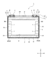
蓄電素子は、図1〜図5に示すように、電極体2と、電極体2を収容するケース3と、ケース3の外側に配置される外部端子4と、電極体2と外部端子4とを繋ぐ集電体5と、ケース3の内部において電極体2及び集電体5を覆う絶縁部材6と、を備える。本実施形態の蓄電素子1では、電極体2と集電体5と絶縁部材6とは、互いに凹凸嵌合している。尚、図3では、電極体2と集電体5と絶縁部材6とは、互いに凹凸嵌合する前の状態を示している。
As shown in FIGS. 1 to 5, the power storage element includes an
電極体2は、活物質層(正極活物質層232、負極活物質層242)が配置されている本体20と、本体20と隣接し且つ集電体5が接続される被接続部26とを有する(図3及び図4参照)。詳しくは、以下の通りである。
The
電極体2は、積層された状態で巻回される電極(正極23及び負極24)を有する。具体的に、電極体2は、巻芯21と、正極23と負極24とが互いに絶縁された状態で積層され且つ巻芯21の周囲に巻回された積層体22と、を備える。電極体2においてリチウムイオンが正極23と負極24との間を移動することにより、蓄電素子1が充放電する。
The
巻芯21は、通常、絶縁材料によって形成される。本実施形態の巻芯21は、偏平な筒状である。この巻芯21は、可撓性又は熱可塑性を有するシートを巻回することによって形成されている。
The winding
正極23は、帯状の金属箔231と、金属箔231に重ねられる正極活物質層232と、を有する。この正極活物質層232は、金属箔231における幅方向の一方の端縁部(非被覆部)を露出させた状態で、該金属箔231に重ねられている。本実施形態の金属箔231は、例えば、アルミニウム箔である。
The
負極24は、帯状の金属箔241と、金属箔241に重ねられる負極活物質層242と、を有する。この負極活物質層242は、金属箔241における幅方向の他方(正極23の金属箔231の非被覆部と反対側)の端縁部(非被覆部)を露出させた状態で、該金属箔241に重ねられている。本実施形態の金属箔241は、例えば、銅箔である。
The
本実施形態の電極体2では、以上のように構成される正極23と負極24とがセパレータ25によって絶縁された状態で巻回されている。即ち、本実施形態の電極体2では、正極23、負極24、及びセパレータ25の積層体22が巻回されている。
In the
セパレータ25は、絶縁性を有する部材であり、正極23と負極24との間に配置される。これにより、電極体2(詳しくは、積層体22)において、正極23と負極24とが互いに絶縁される。また、セパレータ25は、ケース3内において、電解液を保持する。これにより、蓄電素子1の充放電時において、セパレータ25を挟んで交互に積層される正極23と負極24との間を、リチウムイオンが移動可能となる。このセパレータ25は、例えば、ポリエチレン、ポリプロピレン、セルロース、ポリアミドなどの多孔質膜によって構成される。
The
セパレータ25の幅方向の寸法は、負極活物質層242の幅より大きい。セパレータ25は、正極活物質層232と負極活物質層242とが厚さ方向(積層方向)に重なるように幅方向に位置ずれした状態で重ね合わされた正極23と負極24との間に配置される。このとき、正極23の非被覆部と、負極24の非被覆部とは重なっていない。即ち、正極23の非被覆部が、正極23と負極24との重なる領域から幅方向(積層方向と直交する方向)に突出し、且つ、負極24の非被覆部が、正極23と負極24との重なる領域から幅方向(正極23の非被覆部の突出方向と反対の方向)に突出する。このような状態で積層された正極23、負極24、及びセパレータ25(即ち、積層体22)が巻回されることによって、電極体2が形成される。
The width direction dimension of the
本実施形態の電極体2において、正極23の正極活物質層232が配置された部位、負極24の負極活物質層242が配置された部位、及びセパレータ25が積層されることで、電極体2の本体20が構成される。また、正極23の非被覆部又は負極24の非被覆部のみが積層された部位によって、電極体2における被接続部26が構成される。
In the
被接続部26は、電極体2における集電体5と導通される部位である。本実施形態の被接続部26は、巻回された正極23、負極24、及びセパレータ25の巻回中心軸C方向から見て、中空部27(図3及び図4参照)を挟んで二つの部位(分割被接続部)261に分けられている。
The connected
以上のように構成される被接続部26は、電極体2の各極に設けられる。即ち、正極23の非被覆部のみが積層された被接続部26が電極体2における正極の被接続部を構成し、負極24の非被覆部のみが積層された被接続部26が電極体2における負極の被接続部を構成する。
The connected
ケース3は、開口を有するケース本体31と、ケース本体31の開口を塞ぐ(閉じる)蓋板32と、を有する。ケース3は、電極体2及び集電体5等と共に、電解液を内部空間33(図2参照)に収容する。ケース3は、電解液に耐性を有する金属によって形成される。本実施形態のケース3は、例えば、アルミニウム、又は、アルミニウム合金等のアルミニウム系金属材料によって形成される。
The
電解液は、非水溶液系電解液である。電解液は、有機溶媒に電解質塩を溶解させることによって得られる。有機溶媒は、例えば、プロピレンカーボネート及びエチレンカーボネートなどの環状炭酸エステル類、ジメチルカーボネート、ジエチルカーボネート、及びエチルメチルカーボネートなどの鎖状カーボネート類である。電解質塩は、例えば、LiClO4、LiBF4、及びLiPF6である。 The electrolytic solution is a non-aqueous electrolyte solution. The electrolytic solution is obtained by dissolving an electrolyte salt in an organic solvent. The organic solvent is, for example, cyclic carbonates such as propylene carbonate and ethylene carbonate, and chain carbonates such as dimethyl carbonate, diethyl carbonate, and ethyl methyl carbonate. Electrolyte salts are, for example, LiClO 4 , LiBF 4 , and LiPF 6 .
ケース3は、ケース本体31の開口周縁部34と、蓋板32の周縁部とを重ね合わせた状態で接合することによって形成される。また、ケース3では、ケース本体31と蓋板32とによって内部空間33が画定されている。
The
ケース本体31は、板状の閉塞部311と、閉塞部311の周縁に接続される筒状の胴部312と、を備える。
The
閉塞部311は、ケース本体31が開口を上に向けた姿勢で配置されたときにケース本体31の下端に位置する(即ち、前記開口が上を向いたときのケース本体31の底壁となる)部位である。閉塞部311は、該閉塞部311の法線方向から見て、矩形状である。
The closing
以下では、閉塞部311の長辺方向をX軸方向とし、閉塞部311の短辺方向をY軸方向とし、閉塞部311の法線方向をZ軸方向とする。
In the following, the long side direction of the
胴部312は、偏平な角筒状である。胴部312は、閉塞部311の周縁における長辺から延びる一対の長壁部313と、閉塞部311の周縁における短辺から延びる一対の短壁部314とを有する。即ち、一対の長壁部313は、Y軸方向に間隔(詳しくは、閉塞部311の周縁における短辺に相当する間隔)を空けて対向し、一対の短壁部314は、X軸方向に間隔(詳しくは、閉塞部311の周縁における長辺に相当する間隔)を空けて対向する。
The
以上のように、ケース本体31は、開口方向(Z軸方向)における一方の端部が塞がれた角筒形状(即ち、有底角筒形状)を有する。このケース本体31には、電極体2が巻回中心軸C方向をX軸方向と一致させた状態で収容される。
As described above, the
蓋板32は、ケース本体31の開口を塞ぐ板状の部材である。具体的に、蓋板32の輪郭形状は、Z軸方向から見て、ケース本体31の開口周縁部34に対応している。即ち、蓋板32は、Z軸方向から見て、X軸方向に長い矩形板状の部材である。
The
本実施形態の蓋板32には、電解液を注入するための注液穴325が設けられている(図3参照)。注液穴325は、蓋板32をZ軸方向(厚さ方向)に貫通する。この注液穴325は、注液栓326によって密閉(封止)されている。即ち、ケース3は、蓋板32の注液穴325を密閉する注液栓326を有する。本実施形態の注液栓326は、溶接によって蓋板32に固定されている。
The
外部端子4は、他の蓄電素子の外部端子又は外部機器等と電気的に接続される部位である。外部端子4は、導電性を有する部材によって形成される。例えば、外部端子4は、アルミニウム又はアルミニウム合金等のアルミニウム系金属材料、銅又は銅合金等の銅系金属材料等の溶接性の高い金属材料によって形成される。本実施形態の外部端子4は、バスバ等が溶接可能な面41を有する(図1〜図3参照)。
The external terminal 4 is a portion electrically connected to an external terminal of another power storage element, an external device, or the like. The external terminal 4 is formed of a conductive member. For example, the external terminal 4 is formed of a highly weldable metal material such as an aluminum-based metal material such as aluminum or an aluminum alloy, or a copper-based metal material such as copper or a copper alloy. The external terminal 4 of the present embodiment has a
集電体5は、電極体2に接続される接続部52を有する。この集電体5は、導電性を有する部材によって形成され、ケース3の内面に沿って配置される。また、集電体5は、電極体2と通電可能に直接又は間接に接続される。本実施形態の集電体5は、クリップ部材50を介して電極体2と通電可能に接続される。即ち、蓄電素子1は、電極体2と集電体5とを通電可能に接続するクリップ部材50を備える。
The
具体的に、集電体5は、外部端子4と接続される本体51と、本体51から延びる接続部52と、を有する。本体51は、蓋板32に沿ってX軸方向に延びる板状の部位であり、接続部52は、本体51の短壁部314側の端部から長壁部313に沿って閉塞部311側に延びる板状の部位である。本実施形態の集電体5では、Y軸方向における本体51の一方の端縁及び他方の端縁のそれぞれから接続部52が延びている。即ち、本実施形態の集電体5は、一つの本体51と、一対の接続部52と、を有する。この接続部52は、例えばTOX(登録商標)による接合のようなカシメ接合によって電極体2の被接続部26と接合されている。本実施形態の蓄電素子1では、図6にも示すように、接続部52と、クリップ部材50と、電極体2の被接続部26と、絶縁部材6と、が積層された状態でカシメ接合され、互いに凹凸嵌合している。
Specifically, the
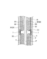
このカシメ接合されている部位(詳しくは、図6における絶縁部材6外側の面602の凹部602Aから、クリップ部材50の対向片502の中空部側の面の凸部502Aまでの部位:以下、「嵌合部位」とも称する。)7は、電極体2の中空部27に向けて突出する(即ち、外側(絶縁部材6側)が凹で内側(中空部27側)が凸となる)ように構成されている。そして、図7に示すように、嵌合部位7は、X軸方向(被接続部26から本体20に向かう方向)から見て本体20の内側に位置している。
The portion to be caulked (specifically, the portion from the
図6に示すように、嵌合部位7において、接続部52は、電極体2(被接続部26)と対向する第一面521に形成される第一凸部521Aと、第一凸部521Aに対して表裏の関係にある(第一面521の反対側の第二面(第一面521の裏面)522にある)第二凹部522Aと、を有する。そして、この接続部52の第一凸部521Aが電極体2(詳しくは、クリップ部材50を介して電極体2)と凹凸嵌合すると共に、接続部52の第二凹部522Aが絶縁部材6と凹凸嵌合している。
As shown in FIG. 6, in the
以上のように構成される集電体5は、図2、図3、及び図5に示すように、電極体2の正極側と負極側とにそれぞれ配置される。本実施形態の蓄電素子1では、ケース3内において、電極体2の正極の被接続部26と、負極の被接続部26とに対応する位置にそれぞれ配置される。正極の集電体5と負極の集電体5とは、異なる素材によって形成される。具体的に、正極の集電体5は、例えば、アルミニウム又はアルミニウム合金によって形成され、負極の集電体5は、例えば、銅又は銅合金によって形成される。
As shown in FIGS. 2, 3, and 5, the
クリップ部材50は、電極体2の被接続部26(詳しくは、分割被接続部261)において積層された正極23又は負極24を束ねるように挟む。これにより、クリップ部材50は、被接続部26において積層される正極23同士、又は負極24同士を確実に導通させる。具体的に、クリップ部材50は、図6〜図8にも示すように、被接続部26の分割被接続部261(積層された正極23又は負極24)を挟んで対向する一対の対向片501、502と、対向片501、502の対応する一方の端部同士を連結する連結部503と、を有する。クリップ部材50は、導電性を有する部材によって形成される。本実施形態のクリップ部材50は、板状の金属材料を断面がU字状となるように曲げ加工することによって形成される。
The
嵌合部位7では、クリップ部材50の一方の対向片(集電体5と対向する対向片)501に、第一凸部521Aが嵌り込み(凹凸嵌合し)、他方の対向片502には、分割被接続部261を介して一方の対向片501が嵌り込んでいる(凹凸嵌合している)。
At the
絶縁部材6は、ケース3(詳しくはケース本体31)と電極体2及び集電体5との間に配置される。この絶縁部材6は、絶縁性を有する樹脂によって形成されている。本実施形態の絶縁部材6は、所定の形状に裁断された絶縁性を有するシート状の部材を折り曲げることで形成された袋状である。
The insulating
嵌合部位7において、絶縁部材6は、集電体5(接続部52)と対向する面601に形成され且つ第二凹部522Aに嵌り込む凸部(絶縁凸部)601Aを有する。この凸部601Aは、第二凹部522Aに沿っている(本実施形態では、密接している)。また、絶縁部材6は、凸部601Aに対して表裏の関係にある(集電体5と対向する面601の反対側の面(面601の裏面)602にある)凹部602Aも有する。
In the
次に、以上のように構成される蓄電素子1の製造方法について、図9〜図11も参照しつつ説明する。
Next, the method of manufacturing the
先ず、外部端子4と集電体5とが蓋板(注液栓326が取り付けられる前の状態の蓋板)32に組み付けられる。次に、電極体2が集電体5にカシメ接合によって取り付けられる。このとき、絶縁部材6も一緒にカシメ接合される。これにより、電極体2と集電体5と絶縁部材6とが互いに凹凸嵌合する。具体的には、以下の通りである。
First, the external terminal 4 and the
先ず、電極体2の分割被接続部261のそれぞれがクリップ部材50によって挟み込まれる。次に、クリップ部材50によって挟み込まれた状態の分割被接続部261と、集電体5の接続部52と、絶縁部材6とが、重ね合わされる。このとき、図9に示すように、絶縁部材6のX軸方向の両端部は、折り曲げられる前の状態である。即ち、絶縁部材6が袋状になっておらず、X軸方向の端部が開放された状態である。
First, each of the divided
続いて、クリップ部材50によって挟み込まれた状態の分割被接続部261と、集電体5の接続部52と、絶縁部材6とが重なっている部位が積層方向へ加圧され、これにより、カシメ接合される。このカシメ接合は、例えば図10及び図11に示すように、中空部27側にダイ(雌金型)81が配置されると共に、電極体2の外側にパンチ(雄金型)80が配置され、重ね合わされた部位(本実施形態の例では、絶縁部材6と、集電体5の接続部52と、クリップ部材50に挟み込まれた状態の分割被接続部261)の一部をパンチ80がダイ81の凹部82に押し込み、これにより、押し込まれた部位が局所的に折れ曲がり、内側の部材にインターロック部(拡径された部位)が形成することによって接合される(圧縮接合される)。本実施形態では、カシメ接合(メカニカルクリンチ)の一種であるTOX(登録商標)接合されている。
Subsequently, the portion where the split connected
以上のカシメ接合が接続部52毎に二箇所ずつ行われ、カシメ接合が終わると、絶縁部材6のX軸方向の両端部がY軸方向の内側に向けて折り曲げられ、絶縁部材6によって電極体2及び集電体5が覆われた状態となる(図5参照)。
The above caulking joints are performed at two locations for each connecting
次に、蓋板32がケース本体31の開口周縁部34に当接するまで、絶縁部材6によって覆われた状態の電極体2がケース本体31に挿入される。これにより、電極体2等が組み付けられた蓋板32によって、ケース本体31の開口が塞がれる。
Next, the
続いて、蓋板32の周縁部がケース本体31の開口周縁部34と重なった状態で、蓋板32の周縁部とケース本体31の開口周縁部34とが溶接(本実施形態の例では、レーザ溶接)される。溶接が終わると、蓋板32の注液穴325からケース本体31内に電解液が注入(注液)され、その後、注液穴325が注液栓326によって封止されることで、蓄電素子1が完成する。
Subsequently, in a state where the peripheral edge portion of the
以上の蓄電素子1によれば、集電体5と絶縁部材6とが互いに凹凸嵌合しているため、電極体2とこれに接続された集電体5とに対する嵌合方向(Y軸方向)と直交する方向への絶縁部材6のずれ(相対移動)が抑えられる。これにより、例えば、蓄電素子1が衝撃によって破損してケース3の蓋板32が外れた場合や、蓄電素子1の材料をリサイクルするために解体作業で電極体2をケース3から取り出す場合などに、絶縁部材6が電極体2及び集電体5に対してずれることに起因するケース3を通じた短絡の発生を抑制することができる。
According to the above
本実施形態の蓄電素子1では、接続部52の第一凸部521Aが電極体2と凹凸嵌合すると共に、第二凹部522Aが絶縁部材6と凹凸嵌合している。このように、接続部52の表裏における同じ位置(表裏の関係にある位置)において電極体2と絶縁部材6とがそれぞれ接続部52に対して凹凸嵌合しているため、本実施形態の蓄電素子1では、接続部52と電極体2とが凹凸嵌合する部位と、接続部52と絶縁部材6とが凹凸嵌合する部位とを別々に形成することなく、電極体2と集電体5とに対する嵌合方向と直交する方向への絶縁部材6の相対移動を抑えることができる。
In the
また、本実施形態の蓄電素子1では、嵌合部位7が、X軸方向(電極体2における被接続部26から本体20に向かう方向)から見て本体20の内側に位置している(図7参照)。このため、X軸方向と直交する方向(本実施形態では、Y軸方向)においてケース3(詳しくは、長壁部313)を電極体2の本体20に近接させて配置するときに、嵌合部位7が邪魔をしない。即ち、前記直交する方向において、図12に示すように電極体2の本体20から嵌合部位7が突出していると、ケース3が該嵌合部位7と当接するため、該ケース3をぎりぎりまで電極体2の本体20に近づけた状態で配置することができないが、本実施形態の蓄電素子1では、ケース3(長壁部313)をぎりぎりまで電極体2の本体20に近づけた状態で配置することができる。
Further, in the
本実施形態の蓄電素子では、絶縁部材6の凸部601Aが、集電体5の第二凹部522Aに沿った状態で、絶縁部材6と集電体5(接続部52)とが嵌合部位7において凹凸嵌合している。このように、集電体5の第二凹部522Aに絶縁部材6の凸部601Aが密接した状態で絶縁部材6と集電体5の接続部52とが凹凸嵌合しているため、嵌合方向(Y軸方向)と直交する方向において嵌合している部位同士(第二凹部522Aと凸部601A)がよりずれ難く(相対移動し難く)なる。
In the power storage element of the present embodiment, the insulating
本実施形態の蓄電素子1の製造方法では、製造された蓄電素子1において、集電体5と絶縁部材6とが互いに凹凸嵌合しているため、電極体2とこれに接続された集電体5とに対する嵌合方向と直交する方向への絶縁部材6のずれが抑えられる。これにより、本実施形態の製造方法によって製造された蓄電素子1において、例えば、蓄電素子1が衝撃によって破損して蓋板32がケース本体31から外れた場合や、蓄電素子1の材料をリサイクルするために解体作業で電極体2をケース3から取り出す場合などに、絶縁部材6が電極体2及び集電体5に対してずれることに起因するケース3を通じての短絡の発生が抑制される。
In the method for manufacturing the
また、本実施形態の蓄電素子1の製造方法では、電極体2と集電体5と絶縁部材6との接合(凹凸嵌合)は、これら電極体2と集電体5と絶縁部材6とが重なっている部位を重ね方向に加圧するカシメ接合によって行われる。このため、カシメ接合の際に集電体5と絶縁部材6との間における嵌合部位7を構成する部位において金属粉等が発生したとしても、集電体5が絶縁部材6に覆われているため前記金属粉等が集電体5と絶縁部材6との間に閉じ込められる。これにより、前記金属粉等が他の部位(例えば、電極23、24とセパレータ25との間等)に移動等することを抑制することができる。
Further, in the method of manufacturing the
尚、本発明の蓄電素子及び蓄電素子の製造方法は、上記実施形態に限定されるものではなく、本発明の要旨を逸脱しない範囲内において種々変更を加え得ることは勿論である。例えば、ある実施形態の構成に他の実施形態の構成を追加することができ、また、ある実施形態の構成の一部を他の実施形態の構成に置き換えることができる。さらに、ある実施形態の構成の一部を削除することができる。 The power storage element and the method for manufacturing the power storage element of the present invention are not limited to the above-described embodiment, and it goes without saying that various modifications can be made without departing from the gist of the present invention. For example, the configuration of one embodiment can be added to the configuration of another embodiment, and a part of the configuration of one embodiment can be replaced with the configuration of another embodiment. In addition, some of the configurations of certain embodiments can be deleted.
上記実施形態の蓄電素子1では、絶縁部材6が、正極の集電体5と負極の集電体5とのそれぞれと凹凸嵌合しているが、この構成に限定されない。絶縁部材6が正極の集電体5と負極の集電体5とのいずれか一方のみと凹凸嵌合する構成でもよい。
In the
また、上記実施形態の蓄電素子1では、電極体2は、クリップ部材50を介して集電体5に接続されているが、この構成に限定されない。電極体2は、集電体5に直接接続されてもよい。この場合、例えば、塑性変形可能な板状の部材が、集電体5(上記実施形態の例では接続部52)との間に分割被接続部261又は被接続部26を挟み込むように配置され、かかる部位がカシメ接合等されることで電極体2と集電体5とが接合される。
Further, in the
また、上記実施形態の蓄電素子1では、絶縁部材6は、集電体5と凹凸嵌合しているが、この構成に限定されない。例えば、集電体5が電極体2の中空部27に差し込まれた状態で電極体2に接合される構成のように、被接続部26と絶縁部材6との間に集電体5が存在しない構成では、絶縁部材6は、電極体2と凹凸嵌合してもよい。この場合、絶縁部材6と電極体2とは、直接、凹凸嵌合してもよく、絶縁部材6と電極体2との間に塑性変形可能で且つ導電性を有する板状の部材等が配置された状態で凹凸嵌合していてもよい。
Further, in the
絶縁部材6と電極体2とが、直接、凹凸嵌合する場合、例えば具体的には、複数枚の平板電極(正極板、負極板)を積層することによって電極体を構成し、その一方の端に配置される正極板の集電箔を十分厚くすると共に、もう一方の端に配置される負極板の集電箔を十分厚くし、それらの厚くした集電箔を塑性変形する部材として絶縁部材6との凹凸嵌合に使用する。また、絶縁部材6と電極体2とが、直接、凹凸嵌合する場合、絶縁部材6は、電極体2における集電体5との接合部位以外の部位で凹凸嵌合していてもよい。
When the insulating
上記実施形態の絶縁部材6では、凸部601Aの反対側(表裏の関係にある部位)が凹部602Aであるが、この構成に限定されない。絶縁部材6の凸部601Aの反対側(表裏の関係にある部位)が平坦でもよい。この場合、絶縁部材6の凸部601Aは、電極体2と集電体5とがカシメ接合された後に、集電体5に形成された凹部に嵌め込まれる。即ち、上記実施形態の蓄電素子1の製造方法では、電極体2と集電体5と絶縁部材6とが一緒にカシメ接合されることで互いに凹凸嵌合しているが、電極体2と集電体5とがカシメ接合された後、該カシメ接合によって形成された凹部(上記実施形態の例では、第二凹部522A)に、絶縁部材6に設けられた凸部601Aが嵌め込まれることで、絶縁部材6が電極体2及び集電体5と凹凸嵌合する構成でもよい。
In the insulating
上記実施形態の蓄電素子1では、集電体5が一対(二つ)の接続部52を有しているが、この構成に限定されない。集電体5は、一つの接続部52を有してもよく、三つ以上の接続部52を有してもよい。
In the
上記実施形態の蓄電素子1では、嵌合部位7がY軸方向における電極体2の外部から中空部27に向かう方向に突出しているが、この構成に限定されない。嵌合部位7は、Y軸方向における中空部27から電極体2の外部に向かう方向に突出してもよい。この場合、上記実施形態の接続部52における第一凸部521Aに相当する部位が凹部(第一凹部)となり、第二凹部522Aに相当する部位が凸部(第二凸部)となる。そして、前記凹部に電極体2(被接続部26)が嵌り込むことで、接続部52と電極体2(被接続部26)とが凹凸嵌合し、且つ、前記凸部が絶縁部材6に嵌り込むことで、接続部52と絶縁部材6とが凹凸嵌合する。
In the
上記実施形態の蓄電素子1では、電極体2と集電体5とが凹凸嵌合する位置と、集電体5と絶縁部材6とが凹凸嵌合する位置とが同じ位置、即ち、嵌合部位7において電極体2と集電体5と絶縁部材6とが一体的に凹凸嵌合しているが、この構成に限定されない。電極体2と集電体5とが凹凸嵌合する位置と、集電体5と絶縁部材6とが凹凸嵌合する位置とが、異なる位置であってもよい。
In the
上記実施形態の蓄電素子1では、嵌合部位7がX軸方向から見て本体20の内側に位置している(図7参照)が、この構成に限定されない。例えば、嵌合部位7の一部が、X軸方向から見て、本体20の外側に位置していてもよい(図12参照)。
In the
上記実施形態の蓄電素子1では、絶縁部材6は、袋状であるが、この構成に限定されない。例えば、絶縁部材6は、電極体2と、ケース3の長壁部313及び閉塞部311との間に配置される構成(X軸方向からみてU字状)であってもよい。
In the
上記実施形態の蓄電素子1では、外部端子4がケース3の外側に配置されているが、この構成に限定されない。外部端子は、ケース3の少なくとも一部によって構成されていてもよい。例えば具体的には、ケース3がアルミニウムによって構成され、正極の集電体5とケース3とがケース3の内部で電気的に接続される(例えば、蓋板32の内側の面に正極集電体5が直接接続されている)ことで、ケース3自体が正極端子(外部端子)を兼ねる構成でもよい。また、ケース3が鉄等によって構成され、負極の集電体5とケース3とがケース3の内部で電気的に接続されることで、ケース3自体が負極端子を兼ねる構成等でもよい。
In the
また、上記実施形態においては、蓄電素子が充放電可能な非水電解質二次電池(例えばリチウムイオン二次電池)として用いられる場合について説明したが、蓄電素子の種類や大きさ(容量)は任意である。また、上記実施形態において、蓄電素子の一例として、リチウムイオン二次電池について説明したが、これに限定されるものではない。例えば、本発明は、種々の二次電池、その他、一次電池や、電気二重層キャパシタ等のキャパシタの蓄電素子にも適用可能である。 Further, in the above embodiment, the case where the power storage element is used as a chargeable / dischargeable non-aqueous electrolyte secondary battery (for example, a lithium ion secondary battery) has been described, but the type and size (capacity) of the power storage element are arbitrary. Is. Further, in the above embodiment, the lithium ion secondary battery has been described as an example of the power storage element, but the present invention is not limited to this. For example, the present invention can be applied to various secondary batteries, other primary batteries, and power storage elements of capacitors such as electric double layer capacitors.
蓄電素子(例えば電池)1は、図13に示すような蓄電装置(蓄電素子が電池の場合は電池モジュール)11に用いられてもよい。蓄電装置11は、少なくとも二つの蓄電素子1と、二つの(異なる)蓄電素子1同士を電気的に接続するバスバ部材12と、を有する。この場合、本発明の技術が少なくとも一つの蓄電素子1に適用されていればよい。
The power storage element (for example, a battery) 1 may be used in a power storage device (battery module when the power storage element is a battery) 11 as shown in FIG. The
1…蓄電素子、2…電極体、20…本体、21…巻芯、22…積層体、23…正極(電極)、231…金属箔、232…正極活物質層、24…負極(電極)、241…金属箔、242…負極活物質層、25…セパレータ、26…被接続部、261…分割被接続部、27…中空部、3…ケース、31…ケース本体、311…閉塞部、312…胴部、313…長壁部、314…短壁部、32…蓋板、325…注液穴、326…注液栓、33…内部空間、34…開口周縁部、4…外部端子、41…面、5…集電体、50…クリップ部材、501、502…対向片、502A…凸部、503…連結部、51…本体、52…接続部、521…第一面、521A…第一凸部、522…第二面、522A…第二凹部、6…絶縁部材、601…面、601A…凸部(絶縁凸部)、602…面、602A…凹部、7…嵌合部位、11…蓄電装置、12…バスバ部材、80…パンチ、81…ダイ、82…凹部、C…巻回中心軸
1 ... power storage element, 2 ... electrode body, 20 ... main body, 21 ... winding core, 22 ... laminate, 23 ... positive electrode (electrode), 231 ... metal leaf, 232 ... positive electrode active material layer, 24 ... negative electrode (electrode), 241 ... Metal leaf, 242 ... Negative electrode active material layer, 25 ... Separator, 26 ... Connected part, 261 ... Divided connected part, 27 ... Hollow part, 3 ... Case, 31 ... Case body, 311 ... Closure part, 312 ... Body part, 313 ... long wall part, 314 ... short wall part, 32 ... lid plate, 325 ... liquid injection hole, 326 ... liquid injection plug, 33 ... internal space, 34 ... opening peripheral edge, 4 ... external terminal, 41 ...
Claims (7)
前記ケースの内部に配置される電極体と、
前記電極体と前記ケースの外側に配置される外部端子又は前記ケースの少なくとも一部によって構成される外部端子とを繋ぐ集電体と、
前記ケースの内部で前記電極体及び前記集電体を覆う絶縁部材と、を備え、
前記集電体は、前記電極体に接続される接続部を有し、
前記接続部は、前記電極体と対向する第一凹部及び該第一凹部に対して表裏の関係にある第二凸部、又は前記電極体と対向する第一凸部及び該第一凸部に対して表裏の関係にある第二凹部、を有し、
前記接続部の前記第一凹部又は前記第一凸部が前記電極体と凹凸嵌合すると共に、前記接続部の前記第二凸部又は前記第二凹部が前記絶縁部材と凹凸嵌合する、蓄電素子。 With the case
The electrode body arranged inside the case and
A current collector that connects the electrode body with an external terminal arranged outside the case or an external terminal composed of at least a part of the case.
An insulating member that covers the electrode body and the current collector inside the case is provided.
The current collector has a connecting portion connected to the electrode body, and has a connecting portion.
The connecting portion is formed on a first concave portion facing the electrode body and a second convex portion having a front-back relationship with the first concave portion, or a first convex portion facing the electrode body and the first convex portion. On the other hand, it has a second recess, which is in a front-to-back relationship.
The first concave portion or the first convex portion of the connecting portion is unevenly fitted to the electrode body, and the second convex portion or the second concave portion of the connecting portion is unevenly fitted to the insulating member. Electric element.
前記絶縁部材と前記接続部と前記電極体とが凹凸嵌合している嵌合部位は、前記被接続部から前記本体に向かう方向から見て前記本体の内側に位置する、請求項1に記載の蓄電素子。 The electrode body has a main body in which an active material layer is arranged, and a connected portion adjacent to the main body and to which the connecting portion of the current collector is connected.
The first aspect of claim 1, wherein the fitting portion where the insulating member, the connecting portion, and the electrode body are unevenly fitted is located inside the main body when viewed from the connected portion toward the main body. Power storage element.
前記絶縁凹部又は前記絶縁凸部は、前記第二凸部又は前記第二凹部に沿っている、請求項1又は2に記載の蓄電素子。 The insulating member has an insulating concave portion into which the second convex portion is fitted, or an insulating convex portion into which the second convex portion is fitted.
The power storage element according to claim 1 or 2, wherein the insulating concave portion or the insulating convex portion is along the second convex portion or the second concave portion.
前記ケースの内部に配置される電極体と、
前記電極体と前記ケースの外側に配置される外部端子又は前記ケースの少なくとも一部によって構成される外部端子とを繋ぐ集電体と、
前記ケースの内部で前記電極体を覆う絶縁部材と、を備え、
前記集電体は、前記電極体に接続される接続部を有し、
前記電極体は、前記接続部と対向する第三凹部及び該第三凹部に対して表裏の関係にある第四凸部、又は前記接続部と対向する第三凸部及び該第三凸部に対して表裏の関係にある第四凹部、を有し、
前記電極体の前記第三凹部又は前記第三凸部が前記接続部と凹凸嵌合すると共に、前記電極体の前記第四凸部又は前記第四凹部が前記絶縁部材と凹凸嵌合する、蓄電素子。 With the case
The electrode body arranged inside the case and
A current collector that connects the electrode body with an external terminal arranged outside the case or an external terminal composed of at least a part of the case.
An insulating member that covers the electrode body inside the case is provided.
The current collector has a connecting portion connected to the electrode body, and has a connecting portion.
The electrode body has a third concave portion facing the connecting portion and a fourth convex portion having a front-back relationship with the third concave portion, or a third convex portion facing the connecting portion and the third convex portion. On the other hand, it has a fourth recess, which is in a front-to-back relationship.
The third concave portion or the third convex portion of the electrode body is concave-convex-fitted with the connection portion, and the fourth convex portion or the fourth concave portion of the electrode body is concave-convex-fitted with the insulating member. element.
前記集電体は、前記電極体に接続される接続部を有し、
前記凹凸嵌合された部位において、
前記接続部は、前記電極体と対向する第一凹部及び該第一凹部に対して表裏の関係にある第二凸部、又は前記電極体と対向する第一凸部及び該第一凸部に対して表裏の関係にある第二凹部、を有し、
前記接続部の前記第一凹部又は前記第一凸部が前記電極体と凹凸嵌合すると共に、前記接続部の前記第二凸部又は前記第二凹部が前記絶縁部材と凹凸嵌合している、蓄電素子の製造方法。 An electrode body disposed within the case, a current collector connecting the external terminals constituted by at least a portion of the external terminal or the casing is arranged on the outside of the electrode body and the case, the inside of the case The electrode body and the insulating member covering the current collector are fitted in a concavo-convex manner .
The current collector has a connecting portion connected to the electrode body, and has a connecting portion.
In the unevenly fitted portion,
The connecting portion is formed on a first concave portion facing the electrode body and a second convex portion having a front-back relationship with the first concave portion, or a first convex portion facing the electrode body and the first convex portion. On the other hand, it has a second recess, which is in a front-to-back relationship.
The first concave portion or the first convex portion of the connecting portion is unevenly fitted to the electrode body, and the second convex portion or the second concave portion of the connecting portion is unevenly fitted to the insulating member. , Manufacturing method of power storage element.
前記凹凸嵌合は、前記電極体と前記集電体と前記絶縁部材とが重なっている部位を重ね方向に加圧するカシメ接合によって行う、蓄電素子の製造方法。 A current collector that connects an electrode body arranged inside the case and an external terminal arranged outside the case or an external terminal composed of at least a part of the case, and the electrode body and the electrode body inside the case. The insulating member covering the current collector is provided with uneven fitting.
The projection fitting is performed by the electrode member and the current collector and the insulating member and the pressurizing crimped in a direction overlapping a portion is overlapped, method of manufacturing a charge reservoir element.
前記集電体は、前記電極体に接続される接続部を有し、
前記凹凸嵌合された部位において、
前記電極体は、前記接続部と対向する第三凹部及び該第三凹部に対して表裏の関係にある第四凸部、又は前記接続部と対向する第三凸部及び該第三凸部に対して表裏の関係にある第四凹部、を有し、
前記電極体の前記第三凹部又は前記第三凸部が前記接続部と凹凸嵌合すると共に、前記電極体の前記第四凸部又は前記第四凹部が前記絶縁部材と凹凸嵌合している、蓄電素子の製造方法。 A current collector that connects an electrode body arranged inside the case, an external terminal arranged outside the case, or an external terminal composed of at least a part of the case, and the inside of the case. The insulating member that covers the electrode body and the insulating member are fitted in a concavo-convex manner .
The current collector has a connecting portion connected to the electrode body, and has a connecting portion.
In the unevenly fitted portion,
The electrode body has a third concave portion facing the connecting portion and a fourth convex portion having a front-back relationship with the third concave portion, or a third convex portion facing the connecting portion and the third convex portion. On the other hand, it has a fourth recess, which is in a front-to-back relationship.
The third concave portion or the third convex portion of the electrode body is concave-convex-fitted with the connection portion, and the fourth convex portion or the fourth concave portion of the electrode body is concave-convex-fitted with the insulating member. , Manufacturing method of power storage element.
Priority Applications (1)
| Application Number | Priority Date | Filing Date | Title |
|---|---|---|---|
| JP2016254056A JP6864863B2 (en) | 2016-12-27 | 2016-12-27 | Power storage element and manufacturing method of power storage element |
Applications Claiming Priority (1)
| Application Number | Priority Date | Filing Date | Title |
|---|---|---|---|
| JP2016254056A JP6864863B2 (en) | 2016-12-27 | 2016-12-27 | Power storage element and manufacturing method of power storage element |
Publications (2)
| Publication Number | Publication Date |
|---|---|
| JP2018107014A JP2018107014A (en) | 2018-07-05 |
| JP6864863B2 true JP6864863B2 (en) | 2021-04-28 |
Family
ID=62787408
Family Applications (1)
| Application Number | Title | Priority Date | Filing Date |
|---|---|---|---|
| JP2016254056A Active JP6864863B2 (en) | 2016-12-27 | 2016-12-27 | Power storage element and manufacturing method of power storage element |
Country Status (1)
| Country | Link |
|---|---|
| JP (1) | JP6864863B2 (en) |
Families Citing this family (1)
| Publication number | Priority date | Publication date | Assignee | Title |
|---|---|---|---|---|
| CN111128544B (en) * | 2020-01-02 | 2021-05-18 | 柯贝尔电能质量技术(上海)有限公司 | Insulating pot body |
Family Cites Families (4)
| Publication number | Priority date | Publication date | Assignee | Title |
|---|---|---|---|---|
| JP2005032477A (en) * | 2003-07-08 | 2005-02-03 | Toyota Motor Corp | Battery and automobile mounting it |
| EP2634832B1 (en) * | 2010-06-21 | 2015-08-05 | Kabushiki Kaisha Toshiba | Battery |
| JP6155896B2 (en) * | 2013-06-21 | 2017-07-05 | 株式会社Gsユアサ | Storage element and method for manufacturing the same |
| JP5841571B2 (en) * | 2013-07-31 | 2016-01-13 | 日立オートモティブシステムズ株式会社 | Secondary battery |
-
2016
- 2016-12-27 JP JP2016254056A patent/JP6864863B2/en active Active
Also Published As
| Publication number | Publication date |
|---|---|
| JP2018107014A (en) | 2018-07-05 |
Similar Documents
| Publication | Publication Date | Title |
|---|---|---|
| KR101808923B1 (en) | Manufacturing method for secondary battery and secondary battery | |
| JP5252937B2 (en) | Stacked battery and method for manufacturing the same | |
| JP6788821B2 (en) | Power storage element, power storage device, and manufacturing method of power storage element | |
| KR102568341B1 (en) | Energy storage device | |
| US8530068B2 (en) | Square battery and manufacturing method of the same | |
| JP2005142026A (en) | Secondary battery | |
| JP2011049065A (en) | Nonaqueous electrolyte battery and method of manufacturing the same | |
| JP2009277604A (en) | Nonaqueous electrolyte secondary battery | |
| KR20140104366A (en) | Energy storage device and energy storage unit | |
| KR20180133698A (en) | Battery Module | |
| CN108140795B (en) | Electric storage element and method for manufacturing electric storage element | |
| JP2019061892A (en) | Power storage element | |
| JP6864863B2 (en) | Power storage element and manufacturing method of power storage element | |
| JP7134543B2 (en) | Electrode assembly including plastic member applied to electrode tab lead connection and secondary battery including the same | |
| JP7133137B2 (en) | Storage element | |
| JP7008461B2 (en) | Power storage element and manufacturing method of power storage element | |
| JP7009884B2 (en) | Power storage element | |
| JP2020149952A (en) | Power storage element | |
| JP6880483B2 (en) | Power storage element | |
| JP5942366B2 (en) | Electricity storage element | |
| JP6731182B2 (en) | Electric storage element and method for manufacturing electric storage element | |
| US20200395577A1 (en) | Energy storage device | |
| JP2019057444A (en) | Power storage element | |
| CN114824683B (en) | Terminal member, secondary battery, and battery pack | |
| JP2019061880A (en) | Power storage element |
Legal Events
| Date | Code | Title | Description |
|---|---|---|---|
| A621 | Written request for application examination |
Free format text: JAPANESE INTERMEDIATE CODE: A621 Effective date: 20191210 |
|
| A977 | Report on retrieval |
Free format text: JAPANESE INTERMEDIATE CODE: A971007 Effective date: 20200827 |
|
| A131 | Notification of reasons for refusal |
Free format text: JAPANESE INTERMEDIATE CODE: A131 Effective date: 20200904 |
|
| A521 | Request for written amendment filed |
Free format text: JAPANESE INTERMEDIATE CODE: A523 Effective date: 20201028 |
|
| TRDD | Decision of grant or rejection written | ||
| A01 | Written decision to grant a patent or to grant a registration (utility model) |
Free format text: JAPANESE INTERMEDIATE CODE: A01 Effective date: 20210305 |
|
| A61 | First payment of annual fees (during grant procedure) |
Free format text: JAPANESE INTERMEDIATE CODE: A61 Effective date: 20210318 |
|
| R150 | Certificate of patent or registration of utility model |
Ref document number: 6864863 Country of ref document: JP Free format text: JAPANESE INTERMEDIATE CODE: R150 |