JP6864757B2 - Video processing equipment, display devices, video processing methods, control programs, and recording media - Google Patents
Video processing equipment, display devices, video processing methods, control programs, and recording media Download PDFInfo
- Publication number
- JP6864757B2 JP6864757B2 JP2019550336A JP2019550336A JP6864757B2 JP 6864757 B2 JP6864757 B2 JP 6864757B2 JP 2019550336 A JP2019550336 A JP 2019550336A JP 2019550336 A JP2019550336 A JP 2019550336A JP 6864757 B2 JP6864757 B2 JP 6864757B2
- Authority
- JP
- Japan
- Prior art keywords
- video
- input
- processing
- videos
- video processing
- Prior art date
- Legal status (The legal status is an assumption and is not a legal conclusion. Google has not performed a legal analysis and makes no representation as to the accuracy of the status listed.)
- Active
Links
Images


Classifications
-
- G—PHYSICS
- G09—EDUCATION; CRYPTOGRAPHY; DISPLAY; ADVERTISING; SEALS
- G09G—ARRANGEMENTS OR CIRCUITS FOR CONTROL OF INDICATING DEVICES USING STATIC MEANS TO PRESENT VARIABLE INFORMATION
- G09G5/00—Control arrangements or circuits for visual indicators common to cathode-ray tube indicators and other visual indicators
- G09G5/36—Control arrangements or circuits for visual indicators common to cathode-ray tube indicators and other visual indicators characterised by the display of a graphic pattern, e.g. using an all-points-addressable [APA] memory
- G09G5/39—Control of the bit-mapped memory
- G09G5/395—Arrangements specially adapted for transferring the contents of the bit-mapped memory to the screen
- G09G5/397—Arrangements specially adapted for transferring the contents of two or more bit-mapped memories to the screen simultaneously, e.g. for mixing or overlay
-
- G—PHYSICS
- G06—COMPUTING; CALCULATING OR COUNTING
- G06T—IMAGE DATA PROCESSING OR GENERATION, IN GENERAL
- G06T1/00—General purpose image data processing
- G06T1/20—Processor architectures; Processor configuration, e.g. pipelining
-
- G—PHYSICS
- G09—EDUCATION; CRYPTOGRAPHY; DISPLAY; ADVERTISING; SEALS
- G09G—ARRANGEMENTS OR CIRCUITS FOR CONTROL OF INDICATING DEVICES USING STATIC MEANS TO PRESENT VARIABLE INFORMATION
- G09G5/00—Control arrangements or circuits for visual indicators common to cathode-ray tube indicators and other visual indicators
- G09G5/36—Control arrangements or circuits for visual indicators common to cathode-ray tube indicators and other visual indicators characterised by the display of a graphic pattern, e.g. using an all-points-addressable [APA] memory
- G09G5/363—Graphics controllers
-
- G—PHYSICS
- G09—EDUCATION; CRYPTOGRAPHY; DISPLAY; ADVERTISING; SEALS
- G09G—ARRANGEMENTS OR CIRCUITS FOR CONTROL OF INDICATING DEVICES USING STATIC MEANS TO PRESENT VARIABLE INFORMATION
- G09G5/00—Control arrangements or circuits for visual indicators common to cathode-ray tube indicators and other visual indicators
- G09G5/36—Control arrangements or circuits for visual indicators common to cathode-ray tube indicators and other visual indicators characterised by the display of a graphic pattern, e.g. using an all-points-addressable [APA] memory
- G09G5/39—Control of the bit-mapped memory
- G09G5/391—Resolution modifying circuits, e.g. variable screen formats
-
- H—ELECTRICITY
- H04—ELECTRIC COMMUNICATION TECHNIQUE
- H04N—PICTORIAL COMMUNICATION, e.g. TELEVISION
- H04N21/00—Selective content distribution, e.g. interactive television or video on demand [VOD]
- H04N21/40—Client devices specifically adapted for the reception of or interaction with content, e.g. set-top-box [STB]; Operations thereof
- H04N21/43—Processing of content or additional data, e.g. demultiplexing additional data from a digital video stream; Elementary client operations, e.g. monitoring of home network or synchronising decoder's clock; Client middleware
- H04N21/431—Generation of visual interfaces for content selection or interaction; Content or additional data rendering
-
- H—ELECTRICITY
- H04—ELECTRIC COMMUNICATION TECHNIQUE
- H04N—PICTORIAL COMMUNICATION, e.g. TELEVISION
- H04N7/00—Television systems
- H04N7/08—Systems for the simultaneous or sequential transmission of more than one television signal, e.g. additional information signals, the signals occupying wholly or partially the same frequency band, e.g. by time division
-
- G—PHYSICS
- G09—EDUCATION; CRYPTOGRAPHY; DISPLAY; ADVERTISING; SEALS
- G09G—ARRANGEMENTS OR CIRCUITS FOR CONTROL OF INDICATING DEVICES USING STATIC MEANS TO PRESENT VARIABLE INFORMATION
- G09G2310/00—Command of the display device
- G09G2310/02—Addressing, scanning or driving the display screen or processing steps related thereto
- G09G2310/0232—Special driving of display border areas
-
- G—PHYSICS
- G09—EDUCATION; CRYPTOGRAPHY; DISPLAY; ADVERTISING; SEALS
- G09G—ARRANGEMENTS OR CIRCUITS FOR CONTROL OF INDICATING DEVICES USING STATIC MEANS TO PRESENT VARIABLE INFORMATION
- G09G2320/00—Control of display operating conditions
- G09G2320/02—Improving the quality of display appearance
- G09G2320/0233—Improving the luminance or brightness uniformity across the screen
-
- G—PHYSICS
- G09—EDUCATION; CRYPTOGRAPHY; DISPLAY; ADVERTISING; SEALS
- G09G—ARRANGEMENTS OR CIRCUITS FOR CONTROL OF INDICATING DEVICES USING STATIC MEANS TO PRESENT VARIABLE INFORMATION
- G09G2320/00—Control of display operating conditions
- G09G2320/06—Adjustment of display parameters
- G09G2320/0686—Adjustment of display parameters with two or more screen areas displaying information with different brightness or colours
-
- G—PHYSICS
- G09—EDUCATION; CRYPTOGRAPHY; DISPLAY; ADVERTISING; SEALS
- G09G—ARRANGEMENTS OR CIRCUITS FOR CONTROL OF INDICATING DEVICES USING STATIC MEANS TO PRESENT VARIABLE INFORMATION
- G09G2360/00—Aspects of the architecture of display systems
- G09G2360/06—Use of more than one graphics processor to process data before displaying to one or more screens
-
- G—PHYSICS
- G09—EDUCATION; CRYPTOGRAPHY; DISPLAY; ADVERTISING; SEALS
- G09G—ARRANGEMENTS OR CIRCUITS FOR CONTROL OF INDICATING DEVICES USING STATIC MEANS TO PRESENT VARIABLE INFORMATION
- G09G2360/00—Aspects of the architecture of display systems
- G09G2360/12—Frame memory handling
- G09G2360/122—Tiling
-
- G—PHYSICS
- G09—EDUCATION; CRYPTOGRAPHY; DISPLAY; ADVERTISING; SEALS
- G09G—ARRANGEMENTS OR CIRCUITS FOR CONTROL OF INDICATING DEVICES USING STATIC MEANS TO PRESENT VARIABLE INFORMATION
- G09G2360/00—Aspects of the architecture of display systems
- G09G2360/18—Use of a frame buffer in a display terminal, inclusive of the display panel
-
- G—PHYSICS
- G09—EDUCATION; CRYPTOGRAPHY; DISPLAY; ADVERTISING; SEALS
- G09G—ARRANGEMENTS OR CIRCUITS FOR CONTROL OF INDICATING DEVICES USING STATIC MEANS TO PRESENT VARIABLE INFORMATION
- G09G2370/00—Aspects of data communication
- G09G2370/20—Details of the management of multiple sources of image data
-
- G—PHYSICS
- G09—EDUCATION; CRYPTOGRAPHY; DISPLAY; ADVERTISING; SEALS
- G09G—ARRANGEMENTS OR CIRCUITS FOR CONTROL OF INDICATING DEVICES USING STATIC MEANS TO PRESENT VARIABLE INFORMATION
- G09G5/00—Control arrangements or circuits for visual indicators common to cathode-ray tube indicators and other visual indicators
- G09G5/36—Control arrangements or circuits for visual indicators common to cathode-ray tube indicators and other visual indicators characterised by the display of a graphic pattern, e.g. using an all-points-addressable [APA] memory
- G09G5/38—Control arrangements or circuits for visual indicators common to cathode-ray tube indicators and other visual indicators characterised by the display of a graphic pattern, e.g. using an all-points-addressable [APA] memory with means for controlling the display position
Description
以下の開示は、複数の入力映像のそれぞれを処理する映像処理装置に関する。 The following disclosure relates to a video processing apparatus that processes each of a plurality of input videos.
特許文献1には、複数の映像データを効率的に処理することを目的とした映像処理装置が開示されている。
映像処理装置によって処理された映像の表示品位を向上させるための工夫については、なお改善の余地がある。本開示の一態様は、従来よりも表示品位に優れた映像を提供することを目的とする。 There is still room for improvement in measures to improve the display quality of the video processed by the video processing device. One aspect of the present disclosure is to provide an image having a display quality superior to that of the conventional one.
上記の課題を解決するために、本開示の一態様に係る映像処理装置は、複数の入力映像を処理する映像処理装置であって、上記複数の入力映像のそれぞれを処理する映像処理部と、上記映像処理部を制御する制御値を設定する制御部と、を備え、上記複数の入力映像のそれぞれを組み合わせて全体入力映像が構成され、上記全体入力映像において、当該全体入力映像を構成する上記複数の入力映像のそれぞれに対応付けられた複数の部分領域のうち、(i)1つの部分領域を第1部分領域、(ii)当該第1部分領域に隣接する部分領域を第2部分領域、として、上記第1部分領域と上記第2部分領域との境界において、上記第1部分領域および上記第2部分領域の一方における画素値を参照して、当該第1部分領域および当該第2部分領域の他方に対して施される処理を隣接境界処理として、上記映像処理部は、上記制御値に応じて上記全体入力映像に対して上記隣接境界処理を実行し、複数の処理後映像を生成する。 In order to solve the above problems, the video processing device according to one aspect of the present disclosure is a video processing device that processes a plurality of input videos, and includes a video processing unit that processes each of the plurality of input videos. A control unit for setting a control value for controlling the video processing unit is provided, and a whole input video is configured by combining each of the plurality of input videos, and the whole input video constitutes the whole input video. Of the plurality of subregions associated with each of the plurality of input videos, (i) one subregion is the first subregion, and (ii) the subregion adjacent to the first subregion is the second subregion. As a reference, at the boundary between the first partial region and the second partial region, the pixel values in one of the first partial region and the second partial region are referred to, and the first partial region and the second partial region are referred to. The processing applied to the other of the above is regarded as the adjacent boundary processing, and the video processing unit executes the adjacent boundary processing on the entire input video according to the control value to generate a plurality of processed images. ..
また、上記の課題を解決するために、本開示の一態様に係る映像処理方法は、複数の入力映像を処理する映像処理方法であって、上記複数の入力映像のそれぞれを処理する映像処理工程と、上記映像処理工程を制御する制御値を設定する制御工程と、を含み、上記複数の入力映像のそれぞれを組み合わせて全体入力映像が構成され、上記全体入力映像において、当該全体入力映像を構成する上記複数の入力映像のそれぞれに対応付けられた複数の部分領域のうち、(i)1つの部分領域を第1部分領域、(ii)当該第1部分領域に隣接する部分領域を第2部分領域、として、上記第1部分領域と上記第2部分領域との境界において、上記第1部分領域および上記第2部分領域の一方における画素値を参照して、当該第1部分領域および当該第2部分領域の他方に対して施される処理を隣接境界処理として、上記映像処理工程は、上記制御値に応じて上記全体入力映像に対して上記隣接境界処理を実行し、複数の処理後映像を生成する工程をさらに含む。 Further, in order to solve the above problems, the video processing method according to one aspect of the present disclosure is a video processing method for processing a plurality of input videos, and is a video processing step for processing each of the plurality of input videos. And a control step of setting a control value for controlling the video processing process, and a whole input video is configured by combining each of the plurality of input videos, and the whole input video is configured in the whole input video. Of the plurality of sub-regions associated with each of the plurality of input videos, (i) one sub-region is the first sub-region, and (ii) the sub-region adjacent to the first sub-region is the second portion. As a region, at the boundary between the first partial region and the second partial region, the first partial region and the second partial region are referred to by referring to the pixel values in one of the first partial region and the second partial region. The processing applied to the other side of the partial region is set as the adjacent boundary processing, and the video processing step executes the adjacent boundary processing on the entire input video according to the control value, and displays a plurality of processed images. It further includes a step of producing.
本開示の一態様に係る映像処理装置によれば、従来よりも表示品位に優れた映像を提供できる。また、本開示の一態様に係る映像処理方法によっても、同様の効果を奏する。 According to the image processing apparatus according to one aspect of the present disclosure, it is possible to provide an image having a display quality superior to that of the conventional one. Further, the same effect can be obtained by the video processing method according to one aspect of the present disclosure.
〔実施形態1〕
以下、実施形態1の表示装置1について述べる。説明の便宜上、以降の各実施形態では、実施形態1にて説明した部材と同じ機能を有する部材については、同じ符号を付記し、その説明を繰り返さない。[Embodiment 1]
Hereinafter, the
(表示装置1の概要)
図1は、表示装置1の要部の構成を示す機能ブロック図である。表示装置1は、バックエンド処理部10(映像処理装置)、表示部70、ユーザ操作受付部75、記憶部90、およびDRAM(Dynamic Random Access Memory)99を備える。なお、「映像」は、「動画像」と称されてもよい。(Overview of Display Device 1)
FIG. 1 is a functional block diagram showing a configuration of a main part of the
バックエンド処理部10は、当該バックエンド処理部10(表示装置1)に入力される複数の映像(より具体的には、映像信号)を外部から取得する。以下、バックエンド処理部10に入力される映像を、入力映像と称する。
The back-
バックエンド処理部10は、複数の入力映像を処理し、複数の処理後の映像を表示部70に出力する。以下、バックエンド処理部10(より具体的には、後述の出力部13)から表示部70に出力される処理後の映像を、出力映像と称する。表示部70は、バックエンド処理部10から出力映像を取得し、当該出力映像を表示する。
The back-
バックエンド処理部10は、入力部11、映像処理部12A〜12D、出力部13、DRAMコントローラ19、および制御部80(映像処理装置)を備える。映像処理部12A〜12Dは、総称的に映像処理部12と称されてもよい。バックエンド処理部10の詳細な構成については後述する。バックエンド処理部10および制御部80は、総称的に映像処理装置と称されてもよい。
The back-
実施形態1では、4つの入力映像(以下、第1入力映像〜第4入力映像)がバックエンド処理部10に入力される場合を例示する。そして、バックエンド処理部10から、4つの出力映像(以下、第1出力映像〜第4出力映像)が出力されるものとする。第1出力映像〜第4出力映像はそれぞれ、第1入力映像〜第4入力映像がバックエンド処理部10によって処理された映像である。
In the first embodiment, a case where four input images (hereinafter, first input image to fourth input image) are input to the back-
実施形態1では、第1入力映像〜第4入力映像および第1出力映像〜第4出力映像のそれぞれが、4K2K映像(4K2Kの解像度を有する映像)である場合を例示する。「4K2K」とは、「水平画素数3840×垂直画素数2160」の解像度を意味する。 In the first embodiment, a case where each of the first input video to the fourth input video and the first output video to the fourth output video is a 4K2K video (video having a resolution of 4K2K) is illustrated. “4K2K” means a resolution of “3840 horizontal pixels × 2160 vertical pixels”.
これに対して、「8K4K」とは、「水平画素数7680×垂直画素数4320」の解像度を意味する。1つの8K4K映像(8K4Kの解像度を有する映像)は、4つ(水平方向に2つ、垂直方向に2つ)の4K2K映像から成る映像として表現できる(例えば後述の図3の(a)を参照)。 On the other hand, "8K4K" means a resolution of "7680 horizontal pixels x 4320 vertical pixels". One 8K4K image (image having a resolution of 8K4K) can be expressed as an image consisting of four (two in the horizontal direction and two in the vertical direction) 4K2K image (see, for example, FIG. 3 (a) described later). ).
従って、第1入力映像〜第4入力映像を組み合わせることにより、1つの8K4K映像としての入力映像(全体入力映像)を表現できる。同様に、第1出力映像〜第4出力映像を組み合わせることにより、1つの8K4K映像としての出力映像(全体出力映像)を表現できる。 Therefore, by combining the first input video to the fourth input video, it is possible to express an input video (whole input video) as one 8K4K video. Similarly, by combining the first output video to the fourth output video, it is possible to express an output video (overall output video) as one 8K4K video.
実施形態1では、表示部70は、8K4K映像を表示可能な8K4Kディスプレイ(解像度8K4Kのディスプレイ)である。表示部70の表示面(表示エリア,表示画面)は、4つ(水平方向に2つ、垂直方向に2つ)の部分表示エリア(後述の図4の部分表示エリア71A〜71D)に区切られている。
In the first embodiment, the
部分表示エリア71A〜71Dはそれぞれ、解像度4K2Kの表示エリアである。実施形態1では、部分表示エリア71A〜71Dはそれぞれ、複数の入力映像(例:第1入力映像〜第4入力映像)と1対1に対応付けられているものとする。それゆえ、部分表示エリア71A〜71Dはそれぞれ、複数の出力映像(例:第1出力映像〜第4出力映像)を表示できる。
The
ユーザ操作受付部75は、ユーザの操作(以下、ユーザ操作)を受け付ける。ユーザ操作は、表示装置1を操作するための赤外線リモコン等による操作である。制御部80は、表示装置1の各部を統括的に制御する。制御部80には、ユーザ操作受付部75からユーザ操作に応じた指令が与えられてよい。記憶部90は、制御部80が実行する各種のプログラム、および当該プログラムによって使用されるデータを格納する。
The user
DRAM99は、バックエンド処理部10が処理を行っている途中の映像を一時的に記憶する。DRAM99は、映像の各フレームを記憶するフレームメモリとして機能する。DRAM99としては、公知のDDR(Double Data Rate)メモリが用いられる。バックエンド処理部10のDRAMコントローラ19は、DRAM99の動作(特に、映像の各フレームの読み込みおよび書き出し)を制御する。
The
(バックエンド処理部10)
図2は、バックエンド処理部10の構成をより詳細に示す機能ブロック図である。図2において、添字「A」〜「D」はそれぞれ、第1入力映像〜第4入力映像(または第1出力映像〜第4出力映像)に対応する各部を指すために用いられてよい。図2以降の各図では、簡単のために、表示部70、ユーザ操作受付部75、および記憶部90の図示が適宜省略されている。(Back-end processing unit 10)
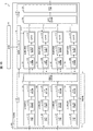
FIG. 2 is a functional block diagram showing the configuration of the back-
以下、説明の便宜上、添字「A」が付された各部(第1入力映像または第1出力映像に対応する各部)について主に説明する。添字「B」〜「D」が付された各部(第2入力映像〜4入力映像または第2出力映像〜第4出力映像のそれぞれに対応する各部)の構成および動作は、添字「A」が付された各部と同様であるため、説明を適宜省略する。 Hereinafter, for convenience of explanation, each part having the subscript "A" (each part corresponding to the first input video or the first output video) will be mainly described. The configuration and operation of each part with the subscripts "B" to "D" (each part corresponding to each of the second input video to the fourth input video or the second output video to the fourth output video) is described by the subscript "A". Since it is the same as each part attached, the description thereof will be omitted as appropriate.
(入力部11)
入力部11には、第1入力映像〜第4入力映像が同時に(並列的に)入力される。入力部11は、入力処理部110A〜110Dおよび同期化処理部114を備えている。区別のため、入力処理部110A〜110Dはそれぞれ、第1入力処理部〜第4入力処理部と称されてもよい。(Input unit 11)
The first input video to the fourth input video are simultaneously (parallel) input to the
入力処理部110Aは、入力IF(Interface)部111A、フォーマット変換部112A、および入力検出部113Aを備える。同様に、入力処理部110B〜110Dはそれぞれ、入力IF部111B〜111D、フォーマット変換部112B〜112D、および入力検出部113B〜113Dを備える。
The
入力IF部111A〜111Dはそれぞれ、HDMI(High-Definition Multimedia Interface)(登録商標)ポートである。具体的には、入力IF部111A〜111Dはそれぞれ、4K2K映像を取得可能なHDMI2.0ポート(HDMI2.0規格に対応したポート)である。現時点では、8K4K映像に対応可能な入力IF規格が普及していない。このため、上述のように、実施形態1では、4K2K映像規格を満たす入力IF部111A〜111Dによって、4つの4K2K映像信号を取得する。
The input IF
本明細書では、互いに同期した複数の映像のそれぞれを、「同期映像」とも称する。具体的には、同期映像とは、(i)垂直同期信号(Vsync)のタイミング、および、(ii)データイネーブル(Data Enable,DE)信号のタイミングが、互いに一致している映像を意味する。 In the present specification, each of the plurality of videos synchronized with each other is also referred to as "synchronized video". Specifically, the synchronized video means a video in which (i) the timing of the vertical synchronization signal (Vsync) and (ii) the timing of the data enable (DE) signal match each other.
バックエンド処理部10では、同期信号としての4つの入力映像(4K2K映像)のそれぞれを、4つの伝送系統(入力処理部110A〜入力処理部110Dのそれぞれ)によって伝送することで、1つの8K4K映像(全体入力映像)を表示部70へ向けて伝送できる。
In the back-
図3の(a)は、同期映像である4つの入力映像から成る1つの8K4K映像(全体入力映像)の例を示す。全体入力映像とは、複数の入力映像を組み合わせることにより構成される1つの映像(入力映像)を意味する。図3の(a)では、1つの全体入力映像IMGAin(8K4K映像)が、4つの第1入力映像IMGAin1〜第4入力映像IMGAin4を組み合わせることによって表現されている。一例として、IMGAinは、スポーツ番組を示す映像コンテンツである。 FIG. 3A shows an example of one 8K4K video (whole input video) composed of four input videos which are synchronized videos. The whole input video means one video (input video) composed by combining a plurality of input videos. In FIG. 3A, one whole input video IMGAin (8K4K video) is represented by combining four first input video IMGAin1 to fourth input video IMGAin4. As an example, IMGAin is a video content showing a sports program.
このように、4つの第1入力映像IMGAin1〜第4入力映像IMGAin4は、1つの全体入力映像IMGAinを構成する部分領域である。つまり、1つの全体入力映像IMGAinは、4つの第1入力映像IMGAin1〜第4入力映像IMGAin4(部分領域)へと分割可能であると理解されてもよい。 As described above, the four first input video IMGAin1 to the fourth input video IMGAin4 are partial regions constituting one whole input video IMGAin. That is, it may be understood that one whole input video IMGAin can be divided into four first input video IMGAin1 to fourth input video IMGAin4 (partial region).
他方、互いに同期していない複数の映像のそれぞれを、「非同期映像」とも称する。図3の(b)はそれぞれ、4つの非同期映像の一例としての、第1入力映像IMGin1〜第4入力映像IMGin4を示す。非同期映像である第1入力映像IMGin1〜第4入力映像IMGin4はそれぞれ、互いに相関性が低い(または相関性を有しない)映像である。 On the other hand, each of the plurality of videos that are not synchronized with each other is also referred to as "asynchronous video". FIG. 3B shows first input video IMGin1 to fourth input video IMGin4 as an example of four asynchronous videos, respectively. The first input video IMGin1 to the fourth input video IMGin4, which are asynchronous videos, are videos having low (or no correlation) correlation with each other.
一例として、
・第1入力映像IMGin1:スポーツ番組を示す映像コンテンツ;
・第2入力映像IMGin2:ニュース番組を示す映像コンテンツ;
・第3入力映像IMGin3:バラエティ番組を示す映像コンテンツ;
・第4入力映像IMGin4:テレビアニメ番組を示す映像コンテンツ;
である。As an example,
・ First input video IMGin1: Video content showing sports programs;
-Second input video IMGin2: Video content showing a news program;
-Third input video IMGin3: Video content showing variety programs;
-Fourth input video IMGin4: Video content showing a TV animation program;
Is.
なお、非同期映像である4つの入力映像によっても、ユーザが意図していない仮想的な全体入力映像が構成される。同様に、非同期映像である4つの出力映像(後述)によっても、ユーザが意図していない仮想的な全体出力映像(後述)が構成される。 It should be noted that the four input images, which are asynchronous images, also constitute a virtual whole input image that is not intended by the user. Similarly, the four output videos (described later), which are asynchronous videos, also constitute a virtual overall output video (described later) that is not intended by the user.
入力IF部111Aは、例えば放送波(例:第1入力映像を搬送する信号)を取得する。入力IF部111Aは、当該搬送波を復号し、第1入力映像を取得する。また、入力IF部111Aは、当該放送波から第1入力映像情報を取得する。第1入力映像情報とは、第1入力映像の内容を示す情報である。同様に、入力IF部111B〜111Dはそれぞれ、第2入力映像情報〜第4入力映像情報(第2入力映像情〜第4入力映像の内容を示す情報)を取得する。
The input IF
フォーマット変換部112Aは、以下に述べる同期化処理および映像処理に適するように、第1入力映像のフォーマットを変換する。入力検出部113Aは、第1入力映像内容情報を検出する。第1入力映像内容情報には、第1入力映像の、(i)コンテンツデータ、(ii)解像度(垂直解像度および水平解像度)、および、(iii)フレームレートを示す情報が含まれていてもよい。
The
制御部80は、入力検出部113A〜入力検出部113Dから、第1入力映像内容情報〜第4入力映像内容情報をそれぞれ取得する。そして、制御部80は、第1入力映像内容情報〜第4入力映像内容情報に基づいて、第1入力映像〜第4入力映像が同期映像であるか否かの判定(以下、同期判定)を行う。当該同期判定を行う方法(以下、同期判定方法)の例については、後述する。
The
制御部80は、同期判定の結果を示す制御値CVを、映像処理部12に出力する。一例として、制御部80は、第1入力映像〜第4入力映像が同期映像である場合、CV=1に設定する。また、制御部80は、第1入力映像〜第4入力映像が非同期映像である場合、CV=0に設定する。以下に述べるように、制御値CVは、映像処理部12を制御するためのフラグ値として用いられてもよい。
The
制御部80において同期判定が行われた後、同期化処理部114の動作が開始される。同期化処理部114は、入力処理部110A〜110Dから第1入力映像〜第4入力映像を取得し、当該第1入力映像〜第4入力映像に対して同期化処理を施す。同期化処理部114における同期化処理は、第1入力映像〜第4入力映像が同期映像であるか否かによらず実行される。
After the synchronization determination is performed by the
具体的には、「同期化処理」とは、後段の映像処理部12(映像処理部12A〜12Dのそれぞれ)における映像処理を可能とするために、第1入力映像〜第4入力映像のそれぞれのタイミングおよびデータの並び方を調整する処理を意味する。同期化処理部114の設定値を変更することで、当該同期化処理部114から各映像が出力されるタイミング、および、各映像のデータの並び方を変更できる。
Specifically, "synchronization processing" refers to each of the first input video to the fourth input video in order to enable video processing in the video processing unit 12 (each of the
同期化処理部114は、DRAMコントローラ19を介して、DRAM99(例:DDRメモリ)にアクセスする。同期化処理部114は、DRAM99をフレームメモリとして使用し、同期化処理を行う。
The
(映像処理部12)
映像処理部12A〜12Dはそれぞれ、同期化処理が施された後の第1入力映像〜第4入力映像に対して、同時に(並列的に)映像処理を施す。区別のため、映像処理部12A〜12Dはそれぞれ、第1映像処理部〜第4映像処理部と称されてもよい。(Video processing unit 12)
The
上記映像処理は、例えば、第1入力映像〜第4入力映像の画質を向上させる処理である。より具体的には、映像処理部12における映像処理は、入力映像の各フレームに対して施す処理を意味する。映像処理には、以下に述べる「境界処理」および「隣接境界処理」が含まれる(後述の図5および図6を参照)。
The video processing is, for example, a process for improving the image quality of the first input video to the fourth input video. More specifically, the video processing in the
第1入力映像〜第4入力映像が同期映像である場合、映像処理部12A〜12Dはそれぞれ、同一の映像処理設定(映像処理パラメータ)を用いて、第1入力映像〜第4入力映像に対する映像処理を行う。つまり、4つの映像処理系統において、同一の映像処理設定が適用される。
When the first input video to the fourth input video are synchronized video, the
他方、第1入力映像〜第4入力映像が非同期映像である場合、映像処理部12A〜12Dはそれぞれ、異なる映像処理設定を用いて、第1入力映像〜第4入力映像に対する映像処理を行う。つまり、4つの映像処理系統において、それぞれ異なる映像処理設定が適用される。
On the other hand, when the first input video to the fourth input video are asynchronous videos, the
加えて、映像処理部12は、制御部80から取得した制御値CVに応じて、映像処理設定(映像処理パラメータ)を変更してもよい。つまり、映像処理部12は、第1入力映像〜第4入力映像が同期映像であるか否かに応じて、映像処理の内容を変更してもよい。
In addition, the
具体的には、映像処理部12は、CV=1である場合(第1入力映像〜第4入力映像が同期映像である場合)には、第1入力映像〜第4入力映像(より具体的には、第1入力映像〜第4入力映像から成る全体入力映像)に対して隣接境界処理を行う。他方、映像処理部12は、CV=0である場合(第1入力映像〜第4入力映像が非同期映像である場合)には、第1入力映像〜第4入力映像に対する隣接境界処理を行わない。
Specifically, when the
映像処理部12Aは、フィルタ処理部120A、フレームレート変換部121A、および拡大部122Aを備える。同様に、映像処理部12B〜映像処理部12Dはそれぞれ、フィルタ処理部120B〜120D、フレームレート変換部121B〜121D、および拡大部122B〜122Dを備える。
The
フィルタ処理部120Aは、第1入力映像の所定の領域に対してフィルタ処理(例:ノイズ除去処理およびエッジ強調処理)を行う。フィルタ処理は、以下に述べる境界処理および隣接境界処理において行われる処理の一例である。
The
フレームレート変換部121Aは、フィルタ処理が施された後の第1入力映像のフレームレートを変換する。一例として、フレームレート変換部121Aは、当該第1入力映像のフレームレートを、60fps(frames per second)から120fpへと増加させる。フレームレート変換部121Aは、例えばデジャダー処理を行ってもよい。
The frame
フレームレート変換部121Aは、DRAMコントローラ19を介して、DRAM99(例:DDRメモリ)にアクセスする。フレームレート変換部121Aは、DRAM99をフレームメモリとして使用し、第1入力映像のフレームレートを変換する。
The frame
第1入力映像の画質の向上が特に重要となる場合、フレームレート変換部121Aは、フレームレート変換部時に、MEMC(Motion Estimation / Motion Compensation)をさらに行ってもよい。この場合、フレームレート変換部121Aは、第1入力映像の現フレーム(第Nフレーム)において、ある画素に隣接する画素を参照し、当該現フレームの動きベクトルを導出する。
When the improvement of the image quality of the first input video is particularly important, the frame
そして、フレームレート変換部121Aは、当該動きベクトルを用いて、直前のフレーム(第N−1フレーム)と現フレームとの間のフレーム(内挿フレーム)を生成する。つまり、フレームレート変換部121Aは、フレーム補間を行うことにより、第1入力映像の画質を向上させる。MEMCは、隣接境界処理の一例である。
Then, the frame
拡大部122Aは、フレームレートが変換された後の第1入力映像を拡大する。実施形態1では、映像処理部12Aにおいて、「フィルタ処理」→「フレームレート変換」→「拡大」の順番で、第1入力映像に対する映像処理が施される場合を例示した。但し、映像処理部12Aにおける各処理の順序は、これに限定されない。
The
映像処理部12Aは、映像処理を施した後の第1入力映像(以下、第1処理後映像)を、出力部13に供給する。同様に、映像処理部12B〜12Dはそれぞれ、第2処理後映像〜第4処理後映像(映像処理を施した後の第2入力映像〜第4入力映像)を、出力部13に供給する。
The
(出力部13)
出力部13は、出力フォーマット変換部130および出力IF部131A〜131Dを備える。出力フォーマット変換部130は、映像処理部12A〜12Dから、複数の処理後映像(第1処理後映像〜第4処理後映像)を取得する。出力部13は、当該複数の処理後映像をさらに処理し、複数の出力映像(第1出力映像〜第4出力映像)を生成する。(Output unit 13)
The
出力フォーマット変換部130は、表示部70における表示に適するように、第1処理後映像〜第4処理後映像のフォーマットを変換する。出力IF部131Aは、フォーマット変換後の第1処理後映像を、第1出力映像として表示部70(より具体的には、部分表示エリア71A)に供給する。同様に、出力IF部131B〜131Dは、フォーマット変換後の第2処理後映像〜第4処理後映像を、第2出力映像〜第4出力映像として表示部70(より具体的には、部分表示エリア71B〜71D)に供給する。
The output
図4の(a)は、同期映像である4つの出力映像から成る1つの全体出力映像の例を示す。全体出力映像とは、複数の出力映像を組み合わせることにより構成される1つの映像(出力映像)を意味する。図4の(a)において、第1出力映像IMGAout1〜第4出力映像IMGAout4は、図3の(a)の第1入力映像IMGAin1〜第4入力映像IMGAin4に対応する。従って、第1出力映像IMGAout1〜第4出力映像IMGAout4も、同期映像である。 FIG. 4A shows an example of one overall output video composed of four output videos which are synchronized videos. The overall output video means one video (output video) composed by combining a plurality of output videos. In FIG. 4A, the first output video IMGAout1 to the fourth output video IMGAout4 correspond to the first input video IMGAin1 to the fourth input video IMGAin4 in FIG. 3A. Therefore, the first output video IMGAout1 to the fourth output video IMGAout4 are also synchronized images.
第1出力映像IMGAout1〜第4出力映像IMGAout4はそれぞれ、部分表示エリア71A〜71D(解像度4K2Kの表示エリア)に表示される。従って、表示部70において、1つの全体出力映像IMGAout(8K4K映像)を、4つの第1出力映像IMGAout1〜第4出力映像IMGAout4の組み合わせとして表示できる。すなわち、全体出力映像IMGAoutは、全体入力映像とIMGAinに対応した8K4K映像となる。
The first output video IMGAout1 to the fourth output video IMGAout4 are displayed in the
図4の(b)は、4つの非同期映像の一例としての、第1出力映像IMGout1〜第4出力映像IMGout4を示す。図4の(b)において、第1出力映像IMGout1〜第4出力映像IMGout4は、図3の(b)の第1入力映像IMGin1〜第4入力映像IMGin4に対応する。従って、第1出力映像IMGout1〜第4出力映像IMGout4も、非同期映像である。この場合、表示部70の部分表示エリア71A〜71Dには、互いに相関性の低い(または相関性を有しない)第1出力映像IMGout1〜第4出力映像IMGout4が表示される。
FIG. 4B shows first output video IMGout1 to fourth output video IMGout4 as an example of four asynchronous videos. In FIG. 4B, the first output video IMGout1 to the fourth output video IMGout4 correspond to the first input video IMGin1 to the fourth input video IMGin4 in FIG. 3B. Therefore, the first output video IMGout1 to the fourth output video IMGout4 are also asynchronous videos. In this case, the first output video IMGout1 to the fourth output video IMGout4 having low (or no correlation) correlation with each other are displayed in the
(境界処理)
図5は、境界処理について説明するための図である。図5では、1つの画像IMG(例:映像の1フレーム)に、タップ数5×5のフィルタFIL1を用いたフィルタ処理を行う場合が例示されている。(Boundary processing)
FIG. 5 is a diagram for explaining boundary processing. FIG. 5 illustrates a case where one image IMG (eg, one frame of a video) is subjected to filter processing using a filter FIL1 having 5 × 5 taps.
図5の(a)には、境界処理が行われない場合が例示されている。図5の(a)では、フィルタFIL1の全体が画像IMGの内部に含まれている。この場合、フィルタFIL1よってカバーされた領域全体において、画像IMGの全ての画素のデータ(画素値)を参照し、当該画素にフィルタ処理を施すことができる。 FIG. 5A illustrates a case where the boundary processing is not performed. In FIG. 5A, the entire filter FIL1 is included inside the image IMG. In this case, in the entire region covered by the filter FIL1, the data (pixel values) of all the pixels of the image IMG can be referred to, and the pixels can be filtered.
図5の(b)には、境界処理が行われる場合が例示されている。図5の(b)では、フィルタFIL1の一部(ハッチング部)が画像IMGの外部に位置している。この場合、ハッチング部には画像IMGの画素が存在していないので、当該ハッチング部では画素値を参照できない。図5の(a)と同様のフィルタ処理を行うことができない。例えば、図5の(a)の場合と同様のフィルタ係数を用いることはできない。 FIG. 5B illustrates a case where boundary processing is performed. In FIG. 5B, a part (hatched portion) of the filter FIL1 is located outside the image IMG. In this case, since the pixels of the image IMG do not exist in the hatched portion, the pixel values cannot be referred to in the hatched portion. The same filtering process as in (a) of FIG. 5 cannot be performed. For example, the same filter coefficient as in the case of (a) of FIG. 5 cannot be used.
従って、フィルタFIL1によってカバーされている画素の位置に応じて、当該画素に対するフィルタ処理の方法を変更する必要がある。例えば、画素の位置に応じてフィルタ係数を変更する必要がある。このように、1つの画像IMGの境界を超えるようにフィルタFIL1が位置している場合には、当該フィルタFIL1の位置に応じたフィルタ処理が行われる。本明細書では、このような映像処理(画像処理)を、境界処理と称する。 Therefore, it is necessary to change the method of filtering the pixels according to the positions of the pixels covered by the filter FIL1. For example, it is necessary to change the filter coefficient according to the position of the pixel. In this way, when the filter FIL1 is positioned so as to cross the boundary of one image IMG, the filter processing is performed according to the position of the filter FIL1. In the present specification, such video processing (image processing) is referred to as boundary processing.
(隣接境界処理)
図6は、隣接境界処理について説明するための図である。なお、隣接境界処理における処理範囲である「境界」の幅は、1画素に限定されない。従って、「隣接境界」は、「隣接部分」と読み替えることもできる。このため、隣接境界処理は、隣接部分処理と称されてもよい。(Adjacent boundary processing)
FIG. 6 is a diagram for explaining the adjacent boundary processing. The width of the "boundary", which is the processing range in the adjacent boundary processing, is not limited to one pixel. Therefore, "adjacent boundary" can be read as "adjacent part". Therefore, the adjacent boundary processing may be referred to as an adjacent partial processing.
図6では、1つの画像(例:IMGAin)が、複数の部分領域(例:IMGAin1〜IMGAin4)に分割されている場合が例示されている。図6の画像は、全体入力映像IMGAinの1フレームである。 FIG. 6 illustrates a case where one image (example: IMGAin) is divided into a plurality of partial regions (example: IMGAin1 to IMGAin4). The image of FIG. 6 is one frame of the entire input video IMGAin.
図6では、簡単のために、IMGAin1〜IMGAin4を、文字「A1」〜「A4」によって表す。この点は、以降の図でも同様である。また、A1〜A4を、部分領域とも称する。実施形態1では、部分領域A1〜A4は、部分表示エリア71A〜71Dに対応付けられている。
In FIG. 6, for the sake of simplicity, IMGAin1 to IMGAin4 are represented by the letters "A1" to "A4". This point is the same in the following figures. Further, A1 to A4 are also referred to as partial regions. In the first embodiment, the partial areas A1 to A4 are associated with the
但し、後述の実施形態2において示されるように、部分領域の数(入力映像の数)は、部分表示エリアの数に等しくなくともよい。つまり、部分領域は、必ずしも部分表示エリアと1対1に対応してなくともよい。例えば、部分領域の個数は、部分表示エリアの数よりも少なくともよい。一例として、実施形態2では、部分領域の数は2つであり、部分表示エリアの数は4つである(図12〜図13を参照)。 However, as shown in the second embodiment described later, the number of partial areas (the number of input images) does not have to be equal to the number of partial display areas. That is, the partial area does not necessarily have to have a one-to-one correspondence with the partial display area. For example, the number of partial areas is at least better than the number of partial display areas. As an example, in the second embodiment, the number of partial areas is two and the number of partial display areas is four (see FIGS. 12 to 13).
部分領域は、全体入力映像において、当該全体入力映像を構成する複数の入力映像のそれぞれを示す領域であればよい。つまり、部分領域は、全体入力映像において、当該全体入力映像を構成する複数の入力映像のそれぞれに対応していればよい。 The partial area may be an area indicating each of a plurality of input images constituting the entire input image in the entire input image. That is, the partial area may correspond to each of the plurality of input images constituting the entire input image in the entire input image.
隣接境界処理とは、1つの映像(画像)を複数の部分領域に分割した場合に行われる映像処理(画像処理)の1つである。具体的には、隣接境界処理とは、「1つの部分領域における他の部分領域との境界において、当該他の部分領域の境界における画素値を参照して当該1つの分割領域の境界に対して施される処理」を意味する。 Adjacent boundary processing is one of video processing (image processing) performed when one video (image) is divided into a plurality of partial regions. Specifically, the adjacent boundary processing refers to "at the boundary with another partial area in one partial area, with reference to the pixel value at the boundary of the other partial area, with respect to the boundary of the one divided area. It means "process to be performed".
図6では、フィルタFIL1の全体が部分領域A1の内部に含まれている。このため、部分領域A1では、フィルタFIL1よってカバーされた領域全体において、部分領域IMGの全ての画素値を参照し、各画素にフィルタ処理を施すことができる。このように、部分領域A1では、隣接境界処理は行われない。 In FIG. 6, the entire filter FIL1 is included inside the partial region A1. Therefore, in the partial region A1, in the entire region covered by the filter FIL1, all the pixel values of the partial region IMG can be referred to, and each pixel can be filtered. As described above, the adjacent boundary processing is not performed in the partial region A1.
これに対して、図6のフィルタFIL2の一部(ハッチング部)は、部分領域A2の内部に含まれていない。フィルタFIL2のハッチング部は、部分領域A1に含まれている。従って、図6の画素P2(部分領域A2の左端の1画素)にフィルタ処理を施す場合には、部分領域A1に属する画素(フィルタFIL2のハッチング部)の画素値を参照する必要がある。このように、フィルタFIL2を用いたフィルタ処理は、隣接境界処理の一例である。 On the other hand, a part (hatched portion) of the filter FIL2 of FIG. 6 is not included in the partial region A2. The hatched portion of the filter FIL2 is included in the partial region A1. Therefore, when filtering the pixel P2 (one pixel at the left end of the partial region A2) of FIG. 6, it is necessary to refer to the pixel value of the pixel belonging to the partial region A1 (hatched portion of the filter FIL2). As described above, the filter processing using the filter FIL2 is an example of the adjacent boundary processing.
また、図6のフィルタFIL4の一部(ハッチング部)は、部分領域A4の内部に含まれていない。フィルタFIL4のハッチング部は、部分領域A1〜A3に含まれている。従って、図6の画素P4(部分領域A2の左上端の1画素)にフィルタ処理を施す場合には、(i)部分領域A1に属する画素の画素値(フィルタFIL4のハッチング部の一部)、(ii)部分領域A2に属する画素の画素値(フィルタFIL4のハッチング部の一部)、および、(iii)部分領域A3に属する画素の画素値(フィルタFIL4のハッチング部の一部)の、それぞれの画素値を参照する必要がある。このように、フィルタFIL4を用いたフィルタ処理も、隣接境界処理の一例である。 Further, a part (hatched portion) of the filter FIL4 of FIG. 6 is not included in the partial region A4. The hatched portion of the filter FIL4 is included in the partial regions A1 to A3. Therefore, when the pixel P4 (one pixel at the upper left end of the partial region A2) of FIG. 6 is filtered, (i) the pixel value of the pixel belonging to the partial region A1 (a part of the hatched portion of the filter FIL4), (Ii) Pixel values of pixels belonging to the partial region A2 (a part of the hatched portion of the filter FIL4) and (iii) Pixel values of the pixels belonging to the partial region A3 (a part of the hatched portion of the filter FIL4), respectively. It is necessary to refer to the pixel value of. As described above, the filter processing using the filter FIL4 is also an example of the adjacent boundary processing.
ここで、複数の部分領域(例:A1〜A4)のうち、1つの部分領域(例:A1)を第1部分領域と称する。また、当該複数の部分領域のうち、第1部分領域に隣接する部分領域(例:A2〜A4)を第2部分領域と称する。 Here, of the plurality of partial regions (example: A1 to A4), one partial region (example: A1) is referred to as a first partial region. Further, among the plurality of partial regions, a partial region (example: A2 to A4) adjacent to the first partial region is referred to as a second partial region.
この場合、「隣接境界処理」とは、「第1部分領域(例:A1)と第2部分領域(A2〜A4)との境界において、当該第1部分領域および当該第2部分領域の一方における画素値を参照して、当該第1部分領域および当該第2部分領域の他方に対して施される処理」であると表現できる。 In this case, "adjacent boundary processing" means "at the boundary between the first partial region (example: A1) and the second partial region (A2 to A4), in one of the first partial region and the second partial region. It can be expressed as "a process performed on the other of the first partial region and the second partial region" with reference to the pixel value.
(同期判定方法の例)
制御部80における同期判定方法としては、例えば、以下の方法1〜方法3が挙げられる。制御部80は、方法1〜方法3の少なくともいずれかを用いて、複数の入力映像(例:第1入力映像〜第4入力映像)が同期映像であるか否かを判定してよい。(Example of synchronization judgment method)
Examples of the synchronization determination method in the
(方法1):入力映像情報を用いて、同期判定を行う。より具体的には、入力映像のコンテンツタイプに基づいて、同期判定を行う。一例として、HDMI規格では、入力映像のAVIInfoFrameにおいて、当該入力映像のコンテンツタイプを示すビットが定義されている。 (Method 1): Synchronous determination is performed using the input video information. More specifically, the synchronization determination is performed based on the content type of the input video. As an example, in the HDMI standard, a bit indicating the content type of the input video is defined in the AVIInfoFrame of the input video.
例えば、第1入力映像〜第4入力映像が、1つの8K4K映像(全体入力映像)を構成するように意図された同期映像である場合を考える。この場合、当該ビットにおいて、当該第1入力映像〜第4入力映像のそれぞれのコンテンツタイプは「8K4K映像」として示されている。従って、制御部80は、第1入力映像〜第4入力映像のそれぞれのコンテンツタイプが、所定のコンテンツタイプ(例:8K4K映像)に一致している場合には、第1入力映像〜第4入力映像が同期映像であると判定してよい。
For example, consider the case where the first input video to the fourth input video are synchronized videos intended to constitute one 8K4K video (whole input video). In this case, in the bit, each content type of the first input video to the fourth input video is indicated as "8K4K video". Therefore, when the content types of the first input video to the fourth input video match a predetermined content type (example: 8K4K video), the
他方、第1入力映像〜第4入力映像が非同期映像である場合、上記ビットにおいて、当該第1入力映像〜第4入力映像のそれぞれのコンテンツタイプは「4K2K映像」として示されている。従って、制御部80は、第1入力映像〜第4入力映像のそれぞれのコンテンツタイプが、上記所定のコンテンツタイプ(例:8K4K映像)に一致していない場合には、第1入力映像〜第4入力映像が非同期映像であると判定してよい。
On the other hand, when the first input video to the fourth input video are asynchronous videos, the content types of the first input video to the fourth input video are indicated as "4K2K video" in the above bits. Therefore, when the content types of the first input video to the fourth input video do not match the predetermined content type (eg, 8K4K video), the
(方法2):入力映像情報を用いて、同期判定を行う。より具体的には、入力映像情報に示されている入力映像の解像度(垂直解像度および水平解像度)とフレームレートとに基づいて、同期判定を行う。 (Method 2): The synchronization determination is performed using the input video information. More specifically, the synchronization determination is performed based on the resolution (vertical resolution and horizontal resolution) of the input video and the frame rate shown in the input video information.
制御部80は、第1入力映像〜第4入力映像のそれぞれの解像度およびフレームレートが一致している場合、第1入力映像〜第4入力映像が同期映像であると判定してよい。第1入力映像〜第4入力映像が1つの8K4K映像(全体入力映像)を構成するように意図された同期映像である場合、各入力映像の解像度およびフレームレートは同一に設定されているためである。
When the resolutions and frame rates of the first input video to the fourth input video match, the
他方、各入力映像間において、解像度およびフレームレートの少なくともいずれかが異なる場合、第1入力映像〜第4入力映像は非同期映像である可能性が高いと言える。非同期映像である第1入力映像〜第4入力映像は、互いに相関性が低い(または相関性を有しない)ためである。従って、制御部80は、第1入力映像〜第4入力映像のそれぞれについて、解像度およびフレームレートの少なくともいずれかが一致していなかった場合、第1入力映像〜第4入力映像が非同期映像であると判定してよい。
On the other hand, if at least one of the resolution and the frame rate is different between the input videos, it can be said that the first input video to the fourth input video are likely to be asynchronous videos. This is because the first input video to the fourth input video, which are asynchronous videos, have low correlation (or no correlation) with each other. Therefore, in the
(方法3):複数の入力映像間の垂直同期信号のスキューに着目し、同期判定を行う。方法3によれば、方法2によりも高精度に同期判定を行うことが可能となる。方法3によれば、解像度およびフレームレートが同一である複数の非同期映像についても、当該映像が非同期映像である旨を適切に判定できる。
(Method 3): Focusing on the skew of the vertical synchronization signal between a plurality of input images, the synchronization determination is performed. According to the
図7は、方法3について説明するための図である。図7では、「入力映像0」と「入力映像1」という、2つの入力映像について考える。入力映像0および入力映像1は、解像度およびフレームレートが同一の非同期映像である。
FIG. 7 is a diagram for explaining the
なお、図7において、入力映像0に関する各記号は、
・Vsync0:入力映像0の垂直同期信号;
・DE0:入力映像0のデータイネーブル信号;
・DE_CNT0:入力映像0のデータイネーブル信号のカウンタ値;
の通りである。同様に、入力映像1に関する各記号は、
・Vsync1:入力映像1の垂直同期信号;
・DE1:入力映像1のデータイネーブル信号;
・DE_CNT1:入力映像1のデータイネーブル信号のカウンタ値;
の通りである。In FIG. 7, each symbol related to the
-Vsync0: Vertical synchronization signal of
DE0: Data enable signal of
DE_CNT0: Counter value of the data enable signal of the
It is a street. Similarly, each symbol related to the
-Vsync1: Vertical synchronization signal of
-DE1: Data enable signal of
DE_CNT1: Counter value of the data enable signal of the
It is a street.
図7に示されるように、DE_CNT0は、DE0のパルスを計数した値を示す。DE0がOFF(Low)となった場合(Vsync0がON(High)となった場合)、DE_CNT0は0にリセットされる。なお、DE_CNT0は、0から5までのいずれかの整数値を取る。DE_CNT1についても同様である。 As shown in FIG. 7, DE_CNT0 indicates a value obtained by counting the pulses of DE0. When DE0 is OFF (Low) (Vsync0 is ON (High)), DE_CNT0 is reset to 0. DE_CNT0 takes any integer value from 0 to 5. The same applies to DE_CNT1.
入力映像0・1が非同期映像である場合、Vsync0がONとなるタイミングとVsync1がONとなるタイミングとの間のずれは、時間の経過に伴って大きくなる。従って、入力映像0・1が非同期映像である場合、1つの時点において、DE_CNT0およびDE_CNT1は異なる値を取ることが一般的である。 When the input video 0.1 is an asynchronous video, the difference between the timing at which Vsync0 is turned on and the timing at which Vsync1 is turned on increases with the passage of time. Therefore, when the input video 0.1 is an asynchronous video, DE_CNT0 and DE_CNT1 generally take different values at one time point.
以上のことから、入力映像0・1が非同期映像である場合、Δ=|DE_CNT0−DE_CNT1|は、入力映像0・1が同期映像である場合に比べて、大きい値となることが期待される。Δは、入力映像0・1間のスキューとも称される。Δは、上記タイミングのずれ(非同期性)を示す指標として用いることができる。 From the above, when the input video 0.1 is an asynchronous video, Δ = | DE_CNT0-DE_CNT1 | is expected to have a larger value than when the input video 0.1 is a synchronous video. .. Δ is also referred to as a skew between the input video 0.1. Δ can be used as an index indicating the timing deviation (asynchrony).
制御部80は、Δが所定の閾値α以下であるか否かを判定することによって、同期判定を行ってもよい。具体的には、制御部80は、Δ≦αという条件(以下、スキュー条件)が満たされる場合には、入力映像0・1が同期映像であると判定してよい。他方、制御部80は、Δ>αとである場合(スキュー条件が満たされない場合)には、入力映像0・1が非同期映像であると判定してよい。
The
換言すれば、制御部80は、上記タイミングのずれが所定の範囲内にある場合に、入力映像0・1が同期映像であると判定してよい。他方、制御部80は、上記タイミングのずれが当該所定の範囲内にない場合に、入力映像0・1が非同期映像であると判定してよい。
In other words, the
一例として、図7に示されるように、Vsync0がONとなるタイミングにおいて、DE_CNT0およびDE_CNT1が読み出される。この場合、Δ=|0−4|=4となる。例えば、α=3として設定されている場合を考える。この場合、Δ>α=3であるので、スキュー条件は満たされない。従って、制御部80は、入力映像0・1が非同期映像であると判定できる。
As an example, as shown in FIG. 7, DE_CNT0 and DE_CNT1 are read at the timing when Vsync0 is turned ON. In this case, Δ = | 0-4 | = 4. For example, consider the case where α = 3 is set. In this case, since Δ> α = 3, the skew condition is not satisfied. Therefore, the
制御部80は、第1入力映像〜第4入力映像のそれぞれについて、スキュー条件に基づいて同期判定を行ってよい。具体的には、制御部80は、第1入力映像〜第4入力映像の全てについて、スキュー条件が満たされる場合、第1入力映像〜第4入力映像が同期映像であると判定する。他方、制御部80は、第1入力映像〜第4入力映像のうち、スキュー条件が満たされない入力映像の組が存在している場合、第1入力映像〜第4入力映像が非同期映像であると判定する。
The
なお、αが過小に設定された場合、適切に同期判定を行うことができない。例えば、α=3として設定された場合、Δ<α=3となり、スキュー条件が満たされない。そこで、入力映像0・1が同期映像であるとして、誤って判定されてしまう。このため、αはある程度大きい値に設定されることが必要である。 If α is set too small, the synchronization determination cannot be performed properly. For example, when α = 3, Δ <α = 3, and the skew condition is not satisfied. Therefore, it is erroneously determined that the input video 0.1 is a synchronized video. Therefore, α needs to be set to a value that is large to some extent.
なお、同期化処理部114では、入力映像同士の同期化がライン(系統)単位で行われる。ライン単位の同期化を行う場合には、ラインメモリが必要となる。Δの値がラインメモリの数(以下、ラインメモリ数)以上となった場合、入力映像は非同期映像として処理される。このため、αはラインメモリ数に依存する。例えば、ラインメモリ数が2の場合、α=2となる。なお、ラインメモリ数は、映像処理部12の映像処理の内容に依存する。
In the
(方法3のさらなる改善例)
上述の通り、入力映像0と入力映像1とが非同期映像である場合、上記タイミングのずれは時間の経過に伴って大きくなる。従って、DE_CNT0およびDE_CNT1が読み出されるタイミング次第では、入力映像0と入力映像1とが非同期映像であったとしても、Δ≦αとなる可能性がある。(Example of further improvement of Method 3)
As described above, when the
つまり、長時間に亘ってスキュー条件が判定され続けた場合、偶発的にスキュー条件が満たされてしまう可能性がある。DE_CNT0およびDE_CNT1のそれぞれが取り得る値は、0から5までに限られているためである。 That is, if the skew condition is continuously determined for a long time, the skew condition may be satisfied accidentally. This is because the values that can be taken by each of DE_CNT0 and DE_CNT1 are limited to 0 to 5.
そこで、一度スキュー条件が満たされたと判定された後に、スキュー条件が満たされないと判定された場合、制御部80は、入力映像0・1が非同期映像であると判定してよい。そして、制御部80は、以降のスキュー条件の判定処理を停止してよい。つまり、制御部80は、判定結果(制御値CV)を固定してよい。これにより、同期判定をさらに高精度に行うことができる。
Therefore, if it is determined that the skew condition is not satisfied after it is determined that the skew condition is satisfied once, the
(表示装置1における処理の流れの一例)
図8は、表示装置1(バックエンド処理部10)における処理の流れの一例を示すフローチャートである。まず、図8の(a)の処理S1〜S4について述べる。入力部11は、複数の入力映像(例:第1入力映像〜第4入力映像)を取得する(S1)。制御部80は、当該入力映像が同期映像であるか否かを判定する(S2,制御工程)。(Example of processing flow in display device 1)
FIG. 8 is a flowchart showing an example of the processing flow in the display device 1 (back-end processing unit 10). First, the processes S1 to S4 of FIG. 8A will be described. The
入力映像が同期映像である場合(S2でYES)、映像処理部12は、入力映像に対して隣接境界処理を実行する(S3,映像処理工程)。他方、入力映像が非同期映像である場合(S2でNO)、映像処理部12は、入力映像に対して隣接境界処理を実行しない(S4,映像処理工程)。
When the input video is a synchronized video (YES in S2), the
図8の(b)の処理S11〜S13は、図8の(a)のS2(制御工程)の内容をより具体的に示す。図8の(b)では、上述の方法1〜方法3を組み合わせて、同期判定が行われている。まず、制御部80は、上述の方法1の通り、入力映像のコンテンツタイプが、所定のコンテンツタイプに一致しているか否かを判定する(S11)。
The processes S11 to S13 of FIG. 8 (b) more specifically show the contents of S2 (control step) of FIG. 8 (a). In FIG. 8B, the synchronization determination is performed by combining the above-mentioned
入力映像のコンテンツタイプが所定のコンテンツタイプに一致している場合(S11でYES)、制御部80は、当該入力映像が同期映像であると判定する。従って、制御部80は、制御値CVを1に設定する(S14)。上述のS3に示されるように、映像処理部12は、制御値CV=1の場合には、入力映像に対する隣接境界処理を開始する。
When the content type of the input video matches the predetermined content type (YES in S11), the
他方、入力映像のコンテンツタイプが所定のコンテンツタイプに一致していない場合(S11でNO)、制御部80は、上述の方法2の通り、入力映像の解像度およびフレームレートが同一であるか否かを判定する(S12)。
On the other hand, when the content type of the input video does not match the predetermined content type (NO in S11), the
入力映像の入力映像の解像度およびフレームレートが一致している場合(S12でYES)、S13に進む。すなわち、制御部80は、上述の方法3の通り、スキュー条件が満たされるか否かをさらに判定する(S13)。スキュー条件が満たされる場合(S13でYES)、上述のS14に進む。
If the resolution and frame rate of the input video of the input video match (YES in S12), the process proceeds to S13. That is, the
他方、入力映像の解像度およびフレームレートが一致していない場合(S12でNO)、または、スキュー条件が満たされない場合(S13でNO)、制御部80は、入力映像が非同期映像である(同期映像でない)と判定する。従って、制御部80は、制御値CVを0に設定する(S15)。上述のS4に示されるように、映像処理部12は、制御値CV=0の場合には、入力映像に対する隣接境界処理を実行しない。
On the other hand, if the resolution and frame rate of the input video do not match (NO in S12), or if the skew condition is not satisfied (NO in S13), the
(表示装置1の効果)
表示装置1によれば、制御値CVに応じて、複数の入力映像に対する隣接境界処理を随意に行うことができる。それゆえ、1つの全体出力映像(例:8K4K映像)を構成する複数の部分領域(例:4K2K映像としての部分領域A1〜A4)の各境界における表示品位の低下を防止できる。(Effect of display device 1)
According to the
図9は、4つの入力映像(IMGAin1〜IMGAin4)が同期映像である場合の、映像処理の様子を示す図である。図9の(a)に示されるように、4つの同期映像に対して、映像処理部12による隣接境界処理を行うことができる。
FIG. 9 is a diagram showing a state of video processing when the four input video (IMGAin1 to IMGAin4) are synchronized video. As shown in FIG. 9A, the
例えば、映像処理部12において、フレームレート変換部121A〜121Dは、MEMCを行ってよい。また、映像処理部12において、拡大部122A〜122Dは、第1部分領域の境界に位置する画素を拡大する場合に、第2部分領域に位置する隣接画素の画素値を参照してもよい。
For example, in the
それゆえ、各境界の表示品位が向上された、4つの処理後映像(第1処理後映像〜第4処理後映)を得ることができる。つまり、4つの処理後映像から成る1つの全体映像(以下、全体処理後映像)の表示品位を向上させることができる。同様に、各境界の表示品位が向上された、4つの出力映像を得ることができる。これにより、4つの出力映像(例:IMGAout1〜IMGAout4)から成る1つの全体出力映像(例:IMGAout)の表示品位を向上させることができる。 Therefore, it is possible to obtain four post-processed images (first post-processed image to fourth post-processed image) in which the display quality of each boundary is improved. That is, it is possible to improve the display quality of one whole image (hereinafter, the image after the whole process) composed of the four processed images. Similarly, it is possible to obtain four output images in which the display quality of each boundary is improved. Thereby, the display quality of one whole output video (example: IMGAout) composed of four output video (example: IMGAout1 to IMGAout4) can be improved.
図9の(b)に示されるように、入力映像が同期映像である場合、映像処理部12は、全体入力映像に対して境界処理をさらに行ってもよい。具体的には、図9の(b)に示されるように、全体入力映像の周縁部に境界処理がさらに行われてよい。これにより、全体出力映像(全体処理後映像)の表示品位を向上させることができる。但し、境界処理は必ずしも行われなくともよい。
As shown in FIG. 9B, when the input video is a synchronized video, the
図10は、4つの入力映像(IMGin1〜IMGin4)が非同期映像である場合の、映像処理の様子を示す図である。図10では、簡単のために、IMGin1〜IMGin4を、文字「A」〜「D」によって表す。この点は、以降の図でも同様である。また、A〜Dを、部分領域とも称する。部分領域A〜Dは、部分表示エリア71A〜71Dに対応付けられている。
FIG. 10 is a diagram showing a state of video processing when the four input video (IMGin1 to IMGin4) are asynchronous video. In FIG. 10, for the sake of simplicity, IMGin1 to IMGin4 are represented by the letters "A" to "D". This point is the same in the following figures. In addition, A to D are also referred to as partial regions. The partial areas A to D are associated with the
複数の入力映像が非同期映像である場合、当該複数の映像は互いに相関性が低い(または相関性を有しない)。このため、隣接境界処理が実行されると、1つの仮想的な全体出力映像を構成する複数の部分領域(A〜D)の各境界の表示品位が低下しうる。 When a plurality of input videos are asynchronous videos, the plurality of videos have low correlation (or no correlation) with each other. Therefore, when the adjacent boundary processing is executed, the display quality of each boundary of the plurality of partial regions (A to D) constituting one virtual overall output video may be deteriorated.
しかしながら、従来の技術では、隣接境界処理の実行の有無を切り替えるという着想は何ら考慮されていない。従って、従来の技術では、入力映像が非同期映像である場合においても、同期映像の場合と同様に、隣接境界処理が行われてしまうという問題があった。 However, in the conventional technique, the idea of switching the execution of the adjacent boundary processing is not considered at all. Therefore, in the conventional technique, even when the input video is an asynchronous video, there is a problem that the adjacent boundary processing is performed as in the case of the synchronized video.
これに対して、図10の(a)に示されるように、表示装置1によれば、非同期映像に対しては、映像処理部12による隣接境界処理を行わない。それゆえ、非同期映像である複数の出力映像(例:IMGout1〜IMGout4)を、各部分表示エリアに表示させる場合にも、表示品位の低下を防ぐことができる。
On the other hand, as shown in FIG. 10A, according to the
例えば、映像処理部12において、フレームレート変換部121A〜121Dは、MEMCを行わず、フレームリピートを行う。また、映像処理部12において、拡大部122A〜122Dは、各画素を拡大する場合、隣接画素の画素値を参照しない。つまり、拡大部122A〜122Dは、単純拡大(画素リピート)を行う。
For example, in the
図10の(b)に示されるように、入力映像が非同期映像である場合、映像処理部12は、各入力映像に境界処理を行ってもよい。具体的には、図10の(b)に示されるように、各入力映像の周縁部に境界処理が行われてよい。これにより、入力映像が非同期映像である場合においても、複数の出力映像(処理後映像)のそれぞれの表示品位をさらに向上させることができる。但し、境界処理は必ずしも行われなくともよい。
As shown in FIG. 10B, when the input video is an asynchronous video, the
以上のように、表示装置1によれば、入力映像が同期映像であるか非同期映像であるか否かに応じて、隣接境界処理の実行の有無を切り替えることができる。つまり、同期映像および非同期映像のそれぞれに対して、より適切な映像処理を行うことができる。その結果、従来よりも表示品位に優れた映像を提供できる。
As described above, according to the
〔変形例〕
(1)実施形態1では、各入力映像が4K2K映像であり、全体入力映像が8K4K映像である場合を例示した。但し、入力映像および全体入力映像の解像度は、これらに限定されない。同様に、全体出力映像の解像度も特に限定されない。表示装置1は、制御値CVに応じて複数の入力映像に対する隣接境界処理の有無を切り替えるものであればよい。[Modification example]
(1) In the first embodiment, a case where each input video is a 4K2K video and the entire input video is an 8K4K video is illustrated. However, the resolution of the input video and the entire input video is not limited to these. Similarly, the resolution of the entire output video is not particularly limited. The
(2)制御部80は、必ずしも同期判定結果に応じて制御値CVを設定する必要はない。つまり、制御値CVは、必ずしも「入力映像が同期信号であるか否か」を示すものでなくともよい。制御値CVは、ユーザによって随意に設定されてもよい。
(2) The
例えば、ユーザ操作受付部75は、制御値CVを設定するためのユーザ操作(例:リモコンの所定のボタンの押下)を、受け付けてもよい。制御部80は、ユーザ操作受付部75が受け付けた上記ユーザ操作に応じて、制御値CVを設定してもよい。
For example, the user
(3)制御部80は、入力映像を分析した結果に基づいて、制御値CVを設定すればよい。上述の同期判定は、上記分析の具体例である。但し、当該分析は、同期判定のみに限定されない。
(3) The
また、制御部80は、複数の入力映像を分析した結果に応じて、映像処理部12A〜12Dのうち、少なくとも2つの映像処理部を動作させてもよい。つまり、制御部80は、複数の入力映像を分析した結果に応じて、映像処理部12に少なくとも2つの入力映像を処理させてもよい。
Further, the
〔実施形態2〕
図11は、実施形態2の表示装置2における入力映像および出力映像について説明するための図である。実施形態2では、実施形態1とは異なり、複数の入力映像として、2つの入力映像(第1入力映像〜第2入力映像)が表示装置2に供給されている。このため、図11では、図1の第3入力映像〜第4入力映像に相当する矢印は、点線で示されている。[Embodiment 2]
FIG. 11 is a diagram for explaining an input image and an output image in the
実施形態2では、第1入力映像〜第2入力映像が映像処理部12A・12Bによってそれぞれ処理され、第1処理後映像〜第2処理後映像が生成される。実施形態1とは異なり、映像処理部12C・12Dにおいて、第3処理後映像〜第4処理後映像は生成されない。このため、図11では、図1の第3処理後映像〜第4処理後映像に相当する矢印は、点線で示されている。
In the second embodiment, the first input video to the second input video are processed by the
出力部13は、映像処理部12A・12Bから、第1処理後映像〜第2処理後映像を取得する。実施形態2の出力部13は、実施形態1とは異なり、第1処理後映像〜第2処理後映像の一部分を分割することで、第1出力映像〜第4出力映像を生成する。実施形態2では、同期映像である2つの4K2K映像(入力映像)を水平方向に並べることで、全体入力映像として1つの8K2K映像(水平画素数7680×垂直画素数2160の解像度を有する映像)が構成されている場合を例示する。このように、実施形態2では、部分領域の数(入力映像の数)は、部分表示エリアの数と相違している。
The
図12の(a)は、実施形態2における全体入力映像の例を示す。図12の(a)では、1つの全体入力映像IMGAinvが、同期映像である2つの第1入力映像IMGAin1v〜第2入力映像IMGAin2vの組み合わせによって表現されている。図12の(b)は、2つの非同期映像の一例としての、第1入力映像IMGin1v〜第2入力映像IMGin2vを示す。 FIG. 12A shows an example of the entire input video according to the second embodiment. In FIG. 12A, one whole input video IMGAinv is represented by a combination of two first input video IMGAin1v to second input video IMGAin2v which are synchronized videos. FIG. 12B shows the first input video IMGin1v to the second input video IMGin2v as an example of the two asynchronous videos.
図13の(a)は、同期映像である4つの出力映像(第1出力映像IMGAout1v〜第4出力映像IMGAout4v)から成る1つ全体出力映像(IMGAoutv)の例を示す。図13の(a)において、第1出力映像IMGAout1vおよび第3出力映像IMGAout3vは、図12の(a)の第1入力映像IMGAin1vに対応する。 FIG. 13A shows an example of one overall output video (IMGAoutv) composed of four output videos (first output video IMGAout1v to fourth output video IMGAout4v) which are synchronized videos. In FIG. 13A, the first output video IMGAout1v and the third output video IMGAout3v correspond to the first input video IMGAin1v in FIG. 12A.
具体的には、出力部13は、第1入力映像IMGAin1v(より厳密には、第1処理後映像)の上端から、垂直方向解像度の1/4に亘る領域全体が黒背景に置き換えられた映像を生成する。出力部13は、当該映像を、第1出力映像IMGAout1vとして出力する。また、出力部13は、第1入力映像IMGAin1v(より厳密には、第1処理後映像)の下端から、垂直方向解像度の1/4に亘る領域全体が黒背景に置き換えられた映像を生成する。出力部13は、当該映像を、第3出力映像IMGAout3vとして出力する。
Specifically, the
同様に、第2出力映像IMGAout2vおよび第4出力映像IMGAout4vは、図12の(a)の第2入力映像IMGAin2vに対応する。具体的には、出力部13は、第2入力映像IMGAin2v(より厳密には、第2処理後映像)の上端から、垂直方向解像度の1/4に亘る領域全体が黒背景に置き換えられた映像を生成する。出力部13は、当該映像を、第2出力映像IMGAout2vとして出力する。また、出力部13は、第2入力映像IMGAin2v(より厳密には、第2処理後映像)の下端から、垂直方向解像度の1/4に亘る領域全体が黒背景に置き換えられた映像を生成する。出力部13は、当該映像を、第4出力映像IMGAout4vとして出力する。
Similarly, the second output video IMGAout2v and the fourth output video IMGAout4v correspond to the second input video IMGAin2v of FIG. 12A. Specifically, the
第1出力映像IMGAout1v〜第4出力映像IMGAout4vも、第1入力映像IMGAin1v〜第2入力映像IMGAin2vと同様に、同期映像である。全体出力映像IMGAoutvは、全体入力映像IMGAinvに対応した映像となる。IMGAoutvは8K4K映像であるが、実質的な解像度は4K2Kとなる。 The first output video IMGAout1v to the fourth output video IMGAout4v are also synchronized videos like the first input video IMGAin1v to the second input video IMGAin2v. The whole output video IMGAoutv is a video corresponding to the whole input video IMGAinv. IMGAoutv is an 8K4K video, but the actual resolution is 4K2K.
図13の(b)は、4つの非同期映像の一例としての、第1出力映像IMGout1v〜第4出力映像IMGout4vを示す。図13の(b)において、第1出力映像IMGout1vおよび第3出力映像IMGout3vは、図12の(b)の第1入力映像IMGin1vに対応する。 FIG. 13B shows the first output video IMGout1v to the fourth output video IMGout4v as an example of the four asynchronous videos. In FIG. 13B, the first output video IMGout1v and the third output video IMGout3v correspond to the first input video IMGin1v in FIG. 12B.
具体的には、出力部13は、第1入力映像IMGin1v(より厳密には、第1処理後映像)の上端から、垂直方向解像度の1/4に亘る領域全体が黒背景に置き換えられた映像を生成する。出力部13は、当該映像を、第1出力映像IMGout1vとして出力する。また、出力部13は、第1入力映像IMGin1v(より厳密には、第1処理後映像)の下端から、垂直方向解像度の1/4に亘る領域全体が黒背景に置き換えられた映像を生成する。出力部13は、当該映像を、第3出力映像IMGout3vとして出力する。
Specifically, the
同様に、第2出力映像IMGout2vおよび第4出力映像IMGout4vは、図12の(b)の第2入力映像IMGin2vに対応する。具体的には、出力部13は、第2入力映像IMGin2v(より厳密には、第2処理後映像)の上端から、垂直方向解像度の1/4に亘る領域全体が黒背景に置き換えられた映像を生成する。出力部13は、当該映像を、第2出力映像IMGout2vとして出力する。また、出力部13は、第2入力映像IMGin2v(より厳密には、第2処理後映像)の下端から、垂直方向解像度の1/4に亘る領域全体が黒背景に置き換えられた映像を生成する。出力部13は、当該映像を、第4出力映像IMGout4vとして出力する。
Similarly, the second output video IMGout2v and the fourth output video IMGout4v correspond to the second input video IMGin2v of FIG. 12B. Specifically, the
第1出力映像IMGout1v〜第4出力映像IMGout4vも、第1入力映像IMGin1v〜第2入力映像IMGin2vと同様に、非同期映像である。 The first output video IMGout1v to the fourth output video IMGout4v are also asynchronous videos like the first input video IMGin1v to the second input video IMGin2v.
図14は、2つの入力映像(IMGAin1v〜IMGAin2v)が同期映像である場合の、映像処理の様子を示す図である。図14の(a)に示されるように、2つの同期映像に対して、映像処理部12による隣接境界処理を行うことができる。図14の(b)に示されるように、全体入力映像の周縁部に境界処理がさらに行われてよい。
FIG. 14 is a diagram showing a state of video processing when two input video (IMGAin1v to IMGAin2v) are synchronized video. As shown in FIG. 14A, the
図15は、2つの入力映像(IMGin1v〜IMGin2v)が非同期映像である場合の、映像処理の様子を示す図である。図15の(a)に示されるように、実施形態1と同様に、非同期映像に対しては、映像処理部12による隣接境界処理が行われない。図15の(b)に示されるように、各出力映像の周縁部に境界処理がさらに行われてよい。
FIG. 15 is a diagram showing a state of video processing when the two input videos (IMGin1v to IMGin2v) are asynchronous videos. As shown in FIG. 15A, as in the first embodiment, the
以上のように、本開示の一態様に係る表示装置において、入力映像の数は、入力IF部の数より少なくともよい。入力映像の数は、複数であればよい。例えば、3つの入力映像を入力部に入力してもよい。同様に、バックエンド処理部10における伝送系統および映像処理系統の数も、4つに限定されない。
As described above, in the display device according to one aspect of the present disclosure, the number of input images is at least better than the number of input IF units. The number of input images may be plural. For example, three input images may be input to the input unit. Similarly, the number of transmission systems and video processing systems in the back-
〔実施形態3〕
図16は、実施形態3の表示装置3の構成を示す機能ブロック図である。表示装置3のバックエンド処理部30(映像処理装置)は、実施形態1のバックエンド処理部10から、制御部80を取り除いた構成である。表示装置3において、制御部80は、バックエンド処理部10の外部に設けられている。このように、制御部80は、必ずしもバックエンド処理部の内部に設けられる必要はない。[Embodiment 3]
FIG. 16 is a functional block diagram showing the configuration of the
〔実施形態4〕
図17は、実施形態4の表示装置4の構成を示す機能ブロック図である。表示装置4のバックエンド処理部40(映像処理装置)は、実施形態1のバックエンド処理部10において、出力部13を出力部43に置き換えた構成である。出力部43は、1つの出力IF部431を有しているという点において、出力部13と異なる。[Embodiment 4]
FIG. 17 is a functional block diagram showing the configuration of the
出力IF部431は、第1出力映像〜第4出力映像を、表示部70(部分表示エリア71A〜71D)へ供給する。このように、出力IF部を一体化することもできる。
The output IF
〔変形例〕
図18は、実施形態4の一変形としての表示装置4vの構成を示す機能ブロック図である。表示装置4vのバックエンド処理部40v(映像処理装置)は、実施形態4のバックエンド処理部40から、制御部80を取り除いた構成である。表示装置4vにおいて、制御部80は、バックエンド処理部10の外部に設けられている。このように、実施形態3・4の構成を組み合わせることもできる。[Modification example]
FIG. 18 is a functional block diagram showing a configuration of the display device 4v as a modification of the fourth embodiment. The back-
〔実施形態5〕
上述の各実施形態とは異なり、バックエンド処理部を複数の機能部に分割することもできる。つまり、バックエンド処理部の個数は、1つに限定されない。一例として、バックエンド処理部は、2つの個別の機能部として実現されてもよい。[Embodiment 5]
Unlike each of the above-described embodiments, the back-end processing unit can be divided into a plurality of functional units. That is, the number of back-end processing units is not limited to one. As an example, the back-end processing unit may be realized as two separate functional units.
〔ソフトウェアによる実現例〕
表示装置1〜4vの制御ブロック(特にバックエンド処理部10〜40vおよび制御部80)は、集積回路(ICチップ)等に形成された論理回路(ハードウェア)によって実現してもよいし、ソフトウェアによって実現してもよい。[Example of realization by software]
The control blocks of the
後者の場合、表示装置1〜4vは、各機能を実現するソフトウェアであるプログラムの命令を実行するコンピュータを備えている。このコンピュータは、例えば少なくとも1つのプロセッサ(制御装置)を備えていると共に、上記プログラムを記憶したコンピュータ読み取り可能な少なくとも1つの記録媒体を備えている。そして、上記コンピュータにおいて、上記プロセッサが上記プログラムを上記記録媒体から読み取って実行することにより、本開示の一態様の目的が達成される。上記プロセッサとしては、例えばCPU(Central Processing Unit)を用いることができる。上記記録媒体としては、「一時的でない有形の媒体」、例えば、ROM(Read Only Memory)等の他、テープ、ディスク、カード、半導体メモリ、プログラマブルな論理回路などを用いることができる。また、上記プログラムを展開するRAM(Random Access Memory)などをさらに備えていてもよい。また、上記プログラムは、該プログラムを伝送可能な任意の伝送媒体(通信ネットワークや放送波等)を介して上記コンピュータに供給されてもよい。なお、本開示の一態様は、上記プログラムが電子的な伝送によって具現化された、搬送波に埋め込まれたデータ信号の形態でも実現され得る。
In the latter case, the
〔まとめ〕
本開示の態様1に係る映像処理装置(バックエンド処理部10および制御部80)は、複数の入力映像(例:IMGAin1〜IMGAin4)を処理する映像処理装置であって、上記複数の入力映像のそれぞれを処理する映像処理部(12,12A〜12D)と、上記映像処理部を制御する制御値(CV)を設定する制御部(80)と、を備え、上記複数の入力映像のそれぞれを組み合わせて全体入力映像(例:IMGAin)が構成され、上記全体入力映像において、当該全体入力映像を構成する上記複数の入力映像のそれぞれに対応付けられた複数の部分領域(例:A1〜A4)のうち、(i)1つの部分領域を第1部分領域(例:A1)、(ii)当該第1部分領域に隣接する部分領域を第2部分領域(例:A2〜A4)、として、上記第1部分領域と上記第2部分領域との境界において、上記第1部分領域および上記第2部分領域の一方における画素値を参照して、当該第1部分領域および当該第2部分領域の他方に対して施される処理を隣接境界処理として、上記映像処理部は、上記制御値に応じて上記全体入力映像に対して上記隣接境界処理を実行し、複数の処理後映像を生成する。[Summary]
The video processing device (back-
上記の構成によれば、制御値に応じて、全体入力映像に対する隣接境界処理を行うか否かを随意に決定できる。それゆえ、隣接境界処理を行わないことが好ましい場合(例:複数の入力映像が非同期映像である場合)には、映像処理部に隣接境界処理を実行させず、処理後映像を生成できる。つまり、隣接境界処理を行うことが好ましい場合(例:複数の入力映像が同期映像である場合)にのみ、映像処理部に隣接境界処理を実行させて、処理後映像を生成できる。その結果、従来よりも表示品位に優れた映像を提供することが可能となる。 According to the above configuration, it is possible to arbitrarily determine whether or not to perform the adjacent boundary processing on the entire input video according to the control value. Therefore, when it is preferable not to perform the adjacent boundary processing (example: when a plurality of input images are asynchronous images), the processed image can be generated without causing the image processing unit to execute the adjacent boundary processing. That is, only when it is preferable to perform the adjacent boundary processing (example: when a plurality of input images are synchronized images), the image processing unit can execute the adjacent boundary processing to generate the processed image. As a result, it becomes possible to provide an image having a display quality superior to that of the conventional one.
本開示の態様2に係る映像処理装置では、上記態様1において、上記制御部は、上記複数の入力映像が同期映像であるか否かを判定した結果に応じて、上記制御値を設定し、上記映像処理部は、上記複数の入力映像が同期映像である場合に、上記全体入力映像に対して上記隣接境界処理を実行し、上記複数の処理後映像を生成することが好ましい。 In the video processing apparatus according to the second aspect of the present disclosure, in the first aspect, the control unit sets the control value according to the result of determining whether or not the plurality of input images are synchronized images. When the plurality of input videos are synchronized videos, the video processing unit preferably executes the adjacent boundary processing on the entire input video to generate the plurality of processed videos.
上記の構成によれば、制御部によって、複数の入力映像が同期映像であるか否かの判定(同期判定)を行うことができる。従って、制御値によって、複数の入力映像が同期映像であるか否を示すことができる。それゆえ、複数の入力映像が同期映像である場合にのみ、映像処理部に隣接境界処理を自動的に実行させることが可能となる。 According to the above configuration, the control unit can determine whether or not the plurality of input images are synchronized images (synchronous determination). Therefore, the control value can indicate whether or not the plurality of input images are synchronized images. Therefore, it is possible to have the video processing unit automatically execute the adjacent boundary processing only when the plurality of input videos are synchronized videos.
本開示の態様3に係る映像処理装置では、上記態様2において、上記制御部は、上記複数の入力映像のコンテンツタイプがそれぞれ所定のコンテンツタイプに一致している場合に、当該複数の入力映像が同期映像であると判定してもよい。 In the video processing apparatus according to the third aspect of the present disclosure, in the second aspect, when the content types of the plurality of input images match the predetermined content types, the control unit can display the plurality of input images. It may be determined that the video is synchronized.
上記の構成によれば、複数の入力映像のそれぞれのコンテンツタイプに基づいて、同期判定を行うことができる。 According to the above configuration, the synchronization determination can be performed based on each content type of the plurality of input videos.
本開示の態様4に係る映像処理装置では、上記態様2または3において、上記制御部は、上記複数の入力映像の解像度およびフレームレートがそれぞれ一致している場合に、当該複数の入力映像が同期映像であると判定してもよい。 In the video processing apparatus according to the fourth aspect of the present disclosure, in the second or third aspect, the control unit synchronizes the plurality of input images when the resolutions and frame rates of the plurality of input images are the same. It may be determined that it is an image.
上記の構成によれば、複数の入力映像のそれぞれの解像度およびフレームレートに基づいて、同期判定を行うことができる。それゆえ、同期判定をより確実に行うことができる。 According to the above configuration, the synchronization determination can be performed based on the respective resolutions and frame rates of the plurality of input images. Therefore, the synchronization determination can be performed more reliably.
本開示の態様5に係る映像処理装置では、上記態様2から4のいずれか1つにおいて、上記制御部は、上記複数の入力映像の垂直同期信号のそれぞれがONとなるタイミングのずれが所定の範囲内にある場合に、当該複数の入力映像が同期映像であると判定してもよい。 In the video processing apparatus according to the fifth aspect of the present disclosure, in any one of the second to fourth aspects, the control unit has a predetermined time lag in which each of the vertical synchronization signals of the plurality of input images is turned on. If it is within the range, it may be determined that the plurality of input images are synchronized images.
上記の構成によれば、複数の入力映像間の垂直同期信号のスキューに着目し、同期判定を行うことができる。それゆえ、同期判定をさらに確実に行うことができる。 According to the above configuration, synchronization determination can be performed by paying attention to the skew of the vertical synchronization signal between a plurality of input images. Therefore, the synchronization determination can be performed more reliably.
本開示の態様6に係る映像処理装置では、上記態様2から5のいずれか1つにおいて、上記映像処理部は、上記複数の入力映像が同期映像である場合に、上記全体入力映像に対して境界処理をさらに実行し、上記複数の処理後映像を生成してもよい。 In the video processing apparatus according to the sixth aspect of the present disclosure, in any one of the second to fifth aspects, the video processing unit may refer to the entire input video when the plurality of input videos are synchronized videos. Boundary processing may be further executed to generate the plurality of processed images.
上記の構成によれば、複数の入力映像が同期映像である場合に、さらに表示品位に優れた映像(複数の処理後映像から成る全体映像、全体処理後映像)を提供できる。 According to the above configuration, when a plurality of input images are synchronized images, it is possible to provide an image having further excellent display quality (an entire image composed of a plurality of processed images, an overall processed image).
本開示の態様7に係る映像処理装置では、上記態様2から6のいずれか1つにおいて、上記映像処理部は、上記複数の入力映像が非同期映像である場合に、当該複数の入力映像のそれぞれに対して境界処理を実行し、上記複数の処理後映像を生成してもよい。 In the video processing apparatus according to the seventh aspect of the present disclosure, in any one of the two to six aspects, the video processing unit performs each of the plurality of input videos when the plurality of input videos are asynchronous videos. Boundary processing may be executed on the subject to generate the above-mentioned plurality of processed images.
上記の構成によれば、複数の入力映像が非同期映像である場合においても、さらに表示品位に優れた映像(複数の処理後映像のそれぞれ)を提供できる。 According to the above configuration, even when a plurality of input images are asynchronous images, it is possible to provide an image having further excellent display quality (each of a plurality of processed images).
本開示の態様8に係る映像処理装置では、上記態様1から7のいずれか1つにおいて、上記制御部は、ユーザ操作に応じて上記制御値を設定してもよい。 In the video processing apparatus according to the eighth aspect of the present disclosure, in any one of the first to seventh aspects, the control unit may set the control value according to the user operation.
本開示の態様9に係る映像処理装置では、上記態様1から8のいずれか1つにおいて、上記制御部は、上記複数の入力映像を分析した結果に応じて、上記映像処理部に少なくとも2つの入力映像を処理させてよい。 In the video processing apparatus according to the ninth aspect of the present disclosure, in any one of the first to eighth aspects, the control unit has at least two in the video processing unit according to the result of analyzing the plurality of input images. The input video may be processed.
本開示の態様10に係る表示装置(1)は、上記態様1から9のいずれか1つに係る映像処理装置と、表示部(70)と、を備えていることが好ましい。 The display device (1) according to the tenth aspect of the present disclosure preferably includes a video processing device according to any one of the first to ninth aspects and a display unit (70).
本開示の態様11に係る映像処理方法は、複数の入力映像を処理する映像処理方法であって、上記複数の入力映像のそれぞれを処理する映像処理工程と、上記映像処理工程を制御する制御値を設定する制御工程と、を含み、上記複数の入力映像のそれぞれを組み合わせて全体入力映像が構成され、上記全体入力映像において、当該全体入力映像を構成する上記複数の入力映像のそれぞれに対応付けられた複数の部分領域のうち、(i)1つの部分領域を第1部分領域、(ii)当該第1部分領域に隣接する部分領域を第2部分領域、として、上記第1部分領域と上記第2部分領域との境界において、上記第1部分領域および上記第2部分領域の一方における画素値を参照して、当該第1部分領域および当該第2部分領域の他方に対して施される処理を隣接境界処理として、上記映像処理工程は、上記制御値に応じて上記全体入力映像に対して上記隣接境界処理を実行し、複数の処理後映像を生成する工程をさらに含む。 The video processing method according to the eleventh aspect of the present disclosure is a video processing method for processing a plurality of input videos, and is a video processing step for processing each of the plurality of input videos and a control value for controlling the video processing steps. The entire input video is configured by combining each of the plurality of input videos including the control process for setting the above, and the entire input video is associated with each of the plurality of input videos constituting the entire input video. Of the plurality of subregions, (i) one subregion is referred to as a first subregion, and (ii) a subregion adjacent to the first subregion is referred to as a second subregion. Processing performed on the first partial region and the other of the second partial region with reference to the pixel values in one of the first partial region and the second partial region at the boundary with the second partial region. The video processing step further includes a step of executing the adjacent boundary processing on the entire input video according to the control value to generate a plurality of processed images.
本開示の各態様に係る映像処理装置は、コンピュータによって実現してもよく、この場合には、コンピュータを上記映像処理装置が備える各部(ソフトウェア要素)として動作させることにより上記映像処理装置をコンピュータにて実現させる映像処理装置の制御プログラム、およびそれを記録したコンピュータ読み取り可能な記録媒体も、本開示の一態様の範疇に入る。 The video processing device according to each aspect of the present disclosure may be realized by a computer. In this case, the video processing device is made into a computer by operating the computer as each part (software element) included in the video processing device. The control program of the video processing apparatus to be realized and the computer-readable recording medium on which the control program is recorded also fall within the scope of one aspect of the present disclosure.
〔付記事項〕
本開示の一態様は上述した各実施形態に限定されるものではなく、請求項に示した範囲で種々の変更が可能であり、異なる実施形態にそれぞれ開示された技術的手段を適宜組み合わせて得られる実施形態についても本開示の一態様の技術的範囲に含まれる。さらに、各実施形態にそれぞれ開示された技術的手段を組み合わせることにより、新しい技術的特徴を形成できる。[Additional notes]
One aspect of the present disclosure is not limited to each of the above-described embodiments, and various modifications can be made within the scope of the claims, and the technical means disclosed in each of the different embodiments can be appropriately combined. Also included in the technical scope of one aspect of the present disclosure. Furthermore, new technical features can be formed by combining the technical means disclosed in each embodiment.
〔本開示の一態様の別の表現〕
本開示の一態様は、以下のようにも表現できる。[Another expression of one aspect of the present disclosure]
One aspect of the present disclosure can also be expressed as follows.
すなわち、本開示の一態様に係る映像処理装置は、入力部と、制御値を決定する制御部と、入力された映像を分けて処理する複数の映像処理部と、上記映像処理部の処理結果を出力する出力部と、を備え、上記映像処理部は、隣接境界処理手段を少なくとも含み、上記制御値によって、上記隣接境界処理手段を作動または停止させる。 That is, the video processing apparatus according to one aspect of the present disclosure includes an input unit, a control unit that determines a control value, a plurality of video processing units that separately process the input video, and a processing result of the video processing unit. The video processing unit includes at least the adjacent boundary processing means, and operates or stops the adjacent boundary processing means according to the control value.
また、本開示の一態様に係る映像処理装置において、上記入力部は、複数の入力処理部と、同期化処理部とを含み、上記複数の入力処理部は、映像信号を同時に入力し、上記同期化処理部は、上記複数の入力処理部が入力した複数の映像信号を同期化してよい。 Further, in the video processing apparatus according to one aspect of the present disclosure, the input unit includes a plurality of input processing units and a synchronization processing unit, and the plurality of input processing units simultaneously input video signals and described above. The synchronization processing unit may synchronize a plurality of video signals input by the plurality of input processing units.
また、本開示の一態様に係る映像処理装置において、上記制御部は、上記複数の入力処理部に入力された映像信号の情報を分析し、分析した結果に基づいて、上記制御値を決定してよい。 Further, in the video processing apparatus according to one aspect of the present disclosure, the control unit analyzes the information of the video signals input to the plurality of input processing units, and determines the control value based on the analysis result. You can do it.
また、本開示の一態様に係る映像処理装置において、上記制御部は、各上記入力処理部に入力された映像信号のコンテンツタイプ、フレームレート、解像度および同期信号のスキューの少なくともいずれか1つを分析してよい。 Further, in the video processing apparatus according to one aspect of the present disclosure, the control unit determines at least one of the content type, frame rate, resolution, and skew of the synchronization signal of the video signal input to each of the input processing units. You may analyze it.
また、本開示の一態様に係る映像処理装置において、上記制御部は、ユーザの入力に従って、上記制御値を決定してよい。 Further, in the video processing device according to one aspect of the present disclosure, the control unit may determine the control value according to the input of the user.
また、本開示の一態様に係る映像処理装置において、上記映像処理部は、境界処理部を有していてよい。 Further, in the video processing apparatus according to one aspect of the present disclosure, the video processing unit may have a boundary processing unit.
また、本開示の一態様に係る映像処理装置において、上記制御部は、上記分析部の分析結果によって、複数の上記映像処理部のうち、少なくとも2つを作動させる機能部を有していてよい。 Further, in the video processing apparatus according to one aspect of the present disclosure, the control unit may have a functional unit that operates at least two of the plurality of video processing units depending on the analysis result of the analysis unit. ..
また、本開示の一態様に係る表示装置は、本開示の一態様に係る映像処理装置と、上記映像処理装置の出力を表示する表示部を備えていてよい。 Further, the display device according to one aspect of the present disclosure may include a video processing device according to one aspect of the present disclosure and a display unit for displaying the output of the video processing device.
また、本開示の一態様に係る映像処理方法は、入力ステップと、制御値を決定する制御ステップと、入力された映像を分けて処理する複数の映像処理ステップと、上記映像処理ステップの処理結果を出力する出力ステップと、を含み、上記映像処理ステップは、隣接境界処理ステップをさらに含み、上記映像処理方法は、上記制御値によって、上記隣接境界処理ステップを実行またはスキップするステップをさらに含む。 Further, the video processing method according to one aspect of the present disclosure includes an input step, a control step for determining a control value, a plurality of video processing steps for separately processing the input video, and a processing result of the video processing step. The video processing step further includes an adjacent boundary processing step, and the video processing method further includes a step of executing or skipping the adjacent boundary processing step according to the control value.
また、本開示の一態様に係る映像処理プログラムは、入力ステップと、制御値を決定する制御ステップと、入力された映像を分けて処理する複数の映像処理ステップと、上記映像処理ステップの処理結果を出力する出力ステップと、を含み、上記映像処理ステップは、隣接境界処理ステップをさらに含み、上記映像処理プログラムは、上記制御値によって、上記隣接境界処理ステップを実行またはスキップするステップをさらに含む。 Further, the video processing program according to one aspect of the present disclosure includes an input step, a control step for determining a control value, a plurality of video processing steps for separately processing the input video, and a processing result of the video processing step. The video processing step further includes an adjacent boundary processing step, and the video processing program further includes a step of executing or skipping the adjacent boundary processing step according to the control value.
また、本開示の一態様に係る記録媒体は、本開示の一態様に係る処理プログラムを記録したコンピュータ読み取り可能な記録媒体であってよい。 Further, the recording medium according to one aspect of the present disclosure may be a computer-readable recording medium on which the processing program according to one aspect of the present disclosure is recorded.
(関連出願の相互参照)
本出願は、2017年11月1日に出願された日本国特許出願:特願2017-212113に対して優先権の利益を主張するものであり、それを参照することにより、その内容の全てが本書に含まれる。(Cross-reference of related applications)
This application claims the benefit of priority to the Japanese patent application filed on November 1, 2017: Japanese Patent Application No. 2017-212113, and by reference to it, all of its contents Included in this book.
1,2,3,4,4v 表示装置
10,30,40,40v バックエンド処理部(映像処理装置)
12,12A〜12D 映像処理部
70 表示部(表示画面)
71A〜71D 部分表示エリア
80 制御部(映像処理装置)
A1 部分領域(第1部分領域)
A2〜A4 部分領域(第2部分領域)
A〜D 部分領域
CV 制御値
IMGAin1〜IMGAin4,IMGAin1v〜IMGAin2v 入力映像
IMGin1〜IMGin4,IMGin1v〜IMGin2v 入力映像
IMGAin,IMGAinv 全体入力映像1,2,3,4,
12, 12A-12D
71A to 71D
A1 partial area (first partial area)
A2 to A4 partial area (second partial area)
A to D partial area CV control value IMGAin1 to IMGAin4, IMGAin1v to IMGAin2v input video IMGin1 to IMGin4, IMGin1v to IMGin2v input video IMGAin, IMGAinv whole input video
Claims (10)
上記複数の入力映像のそれぞれを処理する映像処理部と、
上記複数の入力映像が同期映像であるか否かを上記複数の入力映像に基づき判定した結果に応じて、上記映像処理部を制御する制御値を設定する制御部と、を備え、
上記複数の入力映像のそれぞれを組み合わせて全体入力映像が構成され、
上記全体入力映像において、当該全体入力映像を構成する上記複数の入力映像のそれぞれに対応付けられた複数の部分領域のうち、(i)1つの部分領域を第1部分領域、(ii)当該第1部分領域に隣接する部分領域を第2部分領域、として、
上記第1部分領域と上記第2部分領域との境界において、上記第1部分領域および上記第2部分領域の一方における画素値を参照して、当該第1部分領域および当該第2部分領域の他方に対して施される処理を隣接境界処理として、
上記映像処理部は、上記制御値が、上記複数の入力映像が同期映像であることを示す場合に、上記全体入力映像に対して上記隣接境界処理を実行し、複数の処理後映像を生成し、
上記映像処理部は、上記制御値が、上記複数の入力映像が非同期映像であることを示す場合に、上記複数の入力映像のそれぞれに対して境界処理を実行し、上記複数の処理後映像を生成し、
上記境界処理は、フィルタの全体が上記第1部分領域及び第2部分領域の内部に含まれている場合には、第1のフィルタ処理を行うとともに、上記フィルタの一部が上記第1部分領域及び第2部分領域の外部に位置する場合には、上記フィルタの位置に応じて上記フィルタのフィルタ係数を変更する第2のフィルタ処理を行う
ことを特徴とする映像処理装置。 A video processing device that processes multiple input videos.
A video processing unit that processes each of the above multiple input videos,
A control unit for setting a control value for controlling the video processing unit according to a result of determining whether or not the plurality of input images are synchronized images based on the plurality of input images is provided.
The entire input video is configured by combining each of the above multiple input videos.
In the whole input video, of the plurality of subregions associated with each of the plurality of input videos constituting the whole input video, (i) one subregion is the first subregion, and (ii) the first. A partial area adjacent to one partial area is defined as a second partial area.
At the boundary between the first partial region and the second partial region, referring to the pixel values in one of the first partial region and the second partial region, the first partial region and the other of the second partial region are referred to. The processing applied to is regarded as the adjacent boundary processing.
The video processing unit, the control value, to indicate that the plurality of input images are synchronized video, perform the adjacent boundary processing with respect to the entire input image, and generates a plurality of processed video ,
When the control value indicates that the plurality of input videos are asynchronous videos, the video processing unit executes boundary processing for each of the plurality of input videos, and displays the plurality of processed videos. Generate and
In the boundary processing, when the entire filter is included inside the first sub-region and the second sub-region, the first filter processing is performed, and a part of the filter is part of the first sub-region. An image processing apparatus characterized in that, when it is located outside the second partial region, a second filter process is performed in which the filter coefficient of the filter is changed according to the position of the filter.
表示部と、を備えることを特徴とする表示装置。 The video processing device according to any one of claims 1 to 6.
A display device including a display unit.
上記複数の入力映像のそれぞれを処理する映像処理工程と、
上記複数の入力映像が同期映像であるか否かを上記複数の入力映像に基づき判定した結果に応じて、上記映像処理工程を制御する制御値を設定する制御工程と、を含み、
上記複数の入力映像のそれぞれを組み合わせて全体入力映像が構成され、
上記全体入力映像において、当該全体入力映像を構成する上記複数の入力映像のそれぞれに対応付けられた複数の部分領域のうち、(i)1つの部分領域を第1部分領域、(ii)当該第1部分領域に隣接する部分領域を第2部分領域、として、
上記第1部分領域と上記第2部分領域との境界において、上記第1部分領域および上記第2部分領域の一方における画素値を参照して、当該第1部分領域および当該第2部分領域の他方に対して施される処理を隣接境界処理として、
上記映像処理工程は、上記制御値が、上記複数の入力映像が同期映像であることを示す場合に、上記全体入力映像に対して上記隣接境界処理を実行し、複数の処理後映像を生成し、
上記映像処理工程は、上記制御値が、上記複数の入力映像が非同期映像であることを示す場合に、上記複数の入力映像のそれぞれに対して境界処理を実行し、上記複数の処理後映像を生成し、
上記境界処理は、フィルタの全体が上記第1部分領域及び第2部分領域の内部に含まれている場合には、第1のフィルタ処理を行うとともに、上記フィルタの一部が上記第1部分領域及び第2部分領域の外部に位置する場合には、上記フィルタの位置に応じて上記フィルタのフィルタ係数を変更する第2のフィルタ処理を行う
ことを特徴とする映像処理方法。 It is a video processing method that processes multiple input videos.
A video processing process that processes each of the above multiple input videos,
A control step of setting a control value for controlling the video processing step according to a result of determining whether or not the plurality of input videos are synchronized videos based on the plurality of input videos is included.
The entire input video is configured by combining each of the above multiple input videos.
In the whole input video, of the plurality of subregions associated with each of the plurality of input videos constituting the whole input video, (i) one subregion is the first subregion, and (ii) the first. A partial area adjacent to one partial area is defined as a second partial area.
At the boundary between the first partial region and the second partial region, referring to the pixel values in one of the first partial region and the second partial region, the first partial region and the other of the second partial region are referred to. The processing applied to is regarded as the adjacent boundary processing.
In the video processing step, when the control value indicates that the plurality of input videos are synchronized videos, the adjacent boundary processing is executed on the entire input video to generate a plurality of processed videos. ,
In the video processing step, when the control value indicates that the plurality of input videos are asynchronous videos, boundary processing is executed for each of the plurality of input videos, and the plurality of processed videos are displayed. Generate and
In the boundary processing, when the entire filter is included inside the first sub-region and the second sub-region, the first filter processing is performed, and a part of the filter is part of the first sub-region. And, when it is located outside the second partial region, the image processing method is characterized in that a second filter process is performed in which the filter coefficient of the filter is changed according to the position of the filter.
A computer-readable recording medium on which the control program according to claim 9 is recorded.
Applications Claiming Priority (3)
| Application Number | Priority Date | Filing Date | Title |
|---|---|---|---|
| JP2017212113 | 2017-11-01 | ||
| JP2017212113 | 2017-11-01 | ||
| PCT/JP2018/039954 WO2019087984A1 (en) | 2017-11-01 | 2018-10-26 | Image processing device, display device, image processing method, control program, and recording medium |
Publications (2)
| Publication Number | Publication Date |
|---|---|
| JPWO2019087984A1 JPWO2019087984A1 (en) | 2020-11-19 |
| JP6864757B2 true JP6864757B2 (en) | 2021-04-28 |
Family
ID=66331416
Family Applications (1)
| Application Number | Title | Priority Date | Filing Date |
|---|---|---|---|
| JP2019550336A Active JP6864757B2 (en) | 2017-11-01 | 2018-10-26 | Video processing equipment, display devices, video processing methods, control programs, and recording media |
Country Status (4)
| Country | Link |
|---|---|
| US (1) | US11189254B2 (en) |
| JP (1) | JP6864757B2 (en) |
| CN (1) | CN111295703A (en) |
| WO (1) | WO2019087984A1 (en) |
Families Citing this family (1)
| Publication number | Priority date | Publication date | Assignee | Title |
|---|---|---|---|---|
| CN114666458A (en) * | 2020-12-22 | 2022-06-24 | 富泰华工业(深圳)有限公司 | Image fusion method and device, electronic equipment and storage medium |
Family Cites Families (20)
| Publication number | Priority date | Publication date | Assignee | Title |
|---|---|---|---|---|
| JP4011949B2 (en) * | 2002-04-01 | 2007-11-21 | キヤノン株式会社 | Multi-screen composition device and digital television receiver |
| JP2005339144A (en) * | 2004-05-26 | 2005-12-08 | Sharp Corp | Image processing circuit and liquid crystal display device |
| JP2006005524A (en) * | 2004-06-16 | 2006-01-05 | Ricoh Co Ltd | Image processor and display |
| JP4760288B2 (en) * | 2005-10-13 | 2011-08-31 | ソニー株式会社 | Image display system, display device, image resynthesis device, image resynthesis method, and program |
| WO2008117393A1 (en) * | 2007-03-26 | 2008-10-02 | Mitsubishi Electric Corporation | Video display device and image display method |
| CN102016699B (en) * | 2008-06-27 | 2012-11-21 | 夏普株式会社 | Control device of liquid crystal display device, liquid crystal display device, method for controlling liquid crystal display device, program, and recording medium |
| JP5568884B2 (en) * | 2009-04-02 | 2014-08-13 | セイコーエプソン株式会社 | Video processing apparatus and video processing method |
| KR101560410B1 (en) * | 2009-06-08 | 2015-10-15 | 엘지디스플레이 주식회사 | Image Display System |
| JP5383416B2 (en) * | 2009-10-06 | 2014-01-08 | キヤノン株式会社 | Image processing apparatus, control method therefor, and program |
| JP2013025618A (en) * | 2011-07-22 | 2013-02-04 | Canon Inc | Image processing system, image processing method, and computer program |
| JP2013153410A (en) * | 2011-12-28 | 2013-08-08 | Sharp Corp | Av apparatus |
| US20130208808A1 (en) * | 2012-02-08 | 2013-08-15 | Panasonic Corporation | Image coding method and image decoding method |
| JP5968011B2 (en) * | 2012-04-02 | 2016-08-10 | キヤノン株式会社 | Image processing apparatus and control method thereof |
| WO2015062616A1 (en) * | 2013-10-30 | 2015-05-07 | Barco Control Rooms Gmbh | Synchronization of videos in a display wall |
| JP6429476B2 (en) * | 2014-03-26 | 2018-11-28 | キヤノン株式会社 | Image output device, image display device, and control method thereof |
| JP6381310B2 (en) * | 2014-06-17 | 2018-08-29 | キヤノン株式会社 | Image display apparatus, image display apparatus control method, and program |
| JP2016184775A (en) | 2015-03-25 | 2016-10-20 | セイコーエプソン株式会社 | Video processing device, display device, video processing method |
| JP2017044995A (en) * | 2015-08-28 | 2017-03-02 | キヤノン株式会社 | Display device |
| US20170125064A1 (en) * | 2015-11-03 | 2017-05-04 | Seastar Labs, Inc. | Method and Apparatus for Automatic Video Production |
| JP2017191145A (en) * | 2016-04-11 | 2017-10-19 | キヤノン株式会社 | Image processing apparatus, image processing method, and program |
-
2018
- 2018-10-26 WO PCT/JP2018/039954 patent/WO2019087984A1/en active Application Filing
- 2018-10-26 CN CN201880070443.4A patent/CN111295703A/en active Pending
- 2018-10-26 JP JP2019550336A patent/JP6864757B2/en active Active
- 2018-10-26 US US16/759,661 patent/US11189254B2/en active Active
Also Published As
| Publication number | Publication date |
|---|---|
| US11189254B2 (en) | 2021-11-30 |
| CN111295703A (en) | 2020-06-16 |
| WO2019087984A1 (en) | 2019-05-09 |
| JPWO2019087984A1 (en) | 2020-11-19 |
| US20210134251A1 (en) | 2021-05-06 |
Similar Documents
| Publication | Publication Date | Title |
|---|---|---|
| JP2003298938A5 (en) | ||
| KR102344545B1 (en) | Image processing apparatus and control method thereof | |
| US8830403B1 (en) | Image processing device and image processing method | |
| US10389908B2 (en) | Image processing device, image processing method, and program with reduction and enlargement scaling of image data | |
| EP3099081B1 (en) | Display apparatus and control method thereof | |
| US20130057578A1 (en) | Image processing apparatus and control method thereof | |
| EP3021213A1 (en) | Display apparatus and display methods thereof | |
| CN113728354A (en) | Image processing method and device | |
| JP6864757B2 (en) | Video processing equipment, display devices, video processing methods, control programs, and recording media | |
| JP5072419B2 (en) | Image display device | |
| US8885939B2 (en) | Image processing apparatus configured to perform image processing for plural images and control method thereof | |
| US20140368409A1 (en) | Display system and control method thereof | |
| US7509442B2 (en) | Informational-signal-processing apparatus, functional block, and method of controlling the functional block | |
| US11282483B2 (en) | Full-screen displays | |
| JP2013218002A (en) | Display device | |
| US9749579B2 (en) | Apparatus and method for frame rate conversion | |
| US20220148235A1 (en) | Display apparatus and image processing method thereof for applying random patches to pixel block | |
| JP5676924B2 (en) | Projection apparatus and projection method | |
| US8279207B2 (en) | Information processing apparatus, information processing method, and program | |
| CN104639969A (en) | Full screen page display method and device | |
| US10212316B2 (en) | Video processing apparatus | |
| US8730398B2 (en) | Video output apparatus and control method therefor, and non-transitory recording (storing) medium that records program | |
| CN111835957B (en) | Video processing method, video processing device and video processing equipment | |
| JP5896642B2 (en) | Video processing apparatus, video processing method, and program | |
| US20140139516A1 (en) | Image processing apparatus with transmission formats and control method thereof |
Legal Events
| Date | Code | Title | Description |
|---|---|---|---|
| A521 | Written amendment |
Free format text: JAPANESE INTERMEDIATE CODE: A523 Effective date: 20200324 |
|
| A621 | Written request for application examination |
Free format text: JAPANESE INTERMEDIATE CODE: A621 Effective date: 20200324 |
|
| A131 | Notification of reasons for refusal |
Free format text: JAPANESE INTERMEDIATE CODE: A131 Effective date: 20201208 |
|
| A521 | Written amendment |
Free format text: JAPANESE INTERMEDIATE CODE: A523 Effective date: 20210201 |
|
| TRDD | Decision of grant or rejection written | ||
| A01 | Written decision to grant a patent or to grant a registration (utility model) |
Free format text: JAPANESE INTERMEDIATE CODE: A01 Effective date: 20210309 |
|
| A61 | First payment of annual fees (during grant procedure) |
Free format text: JAPANESE INTERMEDIATE CODE: A61 Effective date: 20210402 |
|
| R150 | Certificate of patent or registration of utility model |
Ref document number: 6864757 Country of ref document: JP Free format text: JAPANESE INTERMEDIATE CODE: R150 |