JP6864620B2 - Bone screw - Google Patents
Bone screw Download PDFInfo
- Publication number
- JP6864620B2 JP6864620B2 JP2017533386A JP2017533386A JP6864620B2 JP 6864620 B2 JP6864620 B2 JP 6864620B2 JP 2017533386 A JP2017533386 A JP 2017533386A JP 2017533386 A JP2017533386 A JP 2017533386A JP 6864620 B2 JP6864620 B2 JP 6864620B2
- Authority
- JP
- Japan
- Prior art keywords
- bone
- screw
- bone screw
- threaded
- pedicle
- Prior art date
- Legal status (The legal status is an assumption and is not a legal conclusion. Google has not performed a legal analysis and makes no representation as to the accuracy of the status listed.)
- Active
Links
- 210000000988 bone and bone Anatomy 0.000 title claims description 124
- 210000000078 claw Anatomy 0.000 claims description 56
- 230000008468 bone growth Effects 0.000 claims description 7
- 238000011282 treatment Methods 0.000 claims description 5
- 230000000087 stabilizing effect Effects 0.000 claims description 3
- 239000000126 substance Substances 0.000 claims description 3
- 230000001737 promoting effect Effects 0.000 claims description 2
- 230000000704 physical effect Effects 0.000 claims 1
- 239000000463 material Substances 0.000 description 26
- 238000003780 insertion Methods 0.000 description 21
- 230000037431 insertion Effects 0.000 description 21
- 239000000523 sample Substances 0.000 description 9
- 238000002513 implantation Methods 0.000 description 6
- 208000007103 Spondylolisthesis Diseases 0.000 description 5
- 238000000034 method Methods 0.000 description 5
- 230000010478 bone regeneration Effects 0.000 description 4
- 208000037873 arthrodesis Diseases 0.000 description 3
- 230000037182 bone density Effects 0.000 description 3
- 230000012010 growth Effects 0.000 description 3
- 238000012986 modification Methods 0.000 description 3
- 230000004048 modification Effects 0.000 description 3
- 230000006641 stabilisation Effects 0.000 description 3
- 238000011105 stabilization Methods 0.000 description 3
- 208000029725 Metabolic bone disease Diseases 0.000 description 2
- 208000001132 Osteoporosis Diseases 0.000 description 2
- RTAQQCXQSZGOHL-UHFFFAOYSA-N Titanium Chemical compound [Ti] RTAQQCXQSZGOHL-UHFFFAOYSA-N 0.000 description 2
- 230000001054 cortical effect Effects 0.000 description 2
- 229910001092 metal group alloy Inorganic materials 0.000 description 2
- 229910001000 nickel titanium Inorganic materials 0.000 description 2
- 239000010935 stainless steel Substances 0.000 description 2
- 229910001220 stainless steel Inorganic materials 0.000 description 2
- 229910052719 titanium Inorganic materials 0.000 description 2
- 239000010936 titanium Substances 0.000 description 2
- 229920000049 Carbon (fiber) Polymers 0.000 description 1
- 206010061246 Intervertebral disc degeneration Diseases 0.000 description 1
- 241000124008 Mammalia Species 0.000 description 1
- 239000004696 Poly ether ether ketone Substances 0.000 description 1
- 206010058907 Spinal deformity Diseases 0.000 description 1
- 229910001069 Ti alloy Inorganic materials 0.000 description 1
- HZEWFHLRYVTOIW-UHFFFAOYSA-N [Ti].[Ni] Chemical compound [Ti].[Ni] HZEWFHLRYVTOIW-UHFFFAOYSA-N 0.000 description 1
- 239000000853 adhesive Substances 0.000 description 1
- 230000001070 adhesive effect Effects 0.000 description 1
- 229910045601 alloy Inorganic materials 0.000 description 1
- 239000000956 alloy Substances 0.000 description 1
- 210000003484 anatomy Anatomy 0.000 description 1
- 238000004873 anchoring Methods 0.000 description 1
- 230000003190 augmentative effect Effects 0.000 description 1
- JUPQTSLXMOCDHR-UHFFFAOYSA-N benzene-1,4-diol;bis(4-fluorophenyl)methanone Chemical compound OC1=CC=C(O)C=C1.C1=CC(F)=CC=C1C(=O)C1=CC=C(F)C=C1 JUPQTSLXMOCDHR-UHFFFAOYSA-N 0.000 description 1
- 239000002639 bone cement Substances 0.000 description 1
- 239000004917 carbon fiber Substances 0.000 description 1
- 239000000788 chromium alloy Substances 0.000 description 1
- 230000006837 decompression Effects 0.000 description 1
- 208000018180 degenerative disc disease Diseases 0.000 description 1
- 230000003412 degenerative effect Effects 0.000 description 1
- 208000037265 diseases, disorders, signs and symptoms Diseases 0.000 description 1
- 208000035475 disorder Diseases 0.000 description 1
- 239000003814 drug Substances 0.000 description 1
- 229940079593 drug Drugs 0.000 description 1
- 238000005516 engineering process Methods 0.000 description 1
- 210000002082 fibula Anatomy 0.000 description 1
- 230000004927 fusion Effects 0.000 description 1
- 230000035876 healing Effects 0.000 description 1
- 229910052588 hydroxylapatite Inorganic materials 0.000 description 1
- 230000006872 improvement Effects 0.000 description 1
- 208000021600 intervertebral disc degenerative disease Diseases 0.000 description 1
- 210000004705 lumbosacral region Anatomy 0.000 description 1
- 230000014759 maintenance of location Effects 0.000 description 1
- 230000007246 mechanism Effects 0.000 description 1
- 229910052751 metal Inorganic materials 0.000 description 1
- 239000002184 metal Substances 0.000 description 1
- 150000002739 metals Chemical class 0.000 description 1
- VNWKTOKETHGBQD-UHFFFAOYSA-N methane Chemical compound C VNWKTOKETHGBQD-UHFFFAOYSA-N 0.000 description 1
- 238000002156 mixing Methods 0.000 description 1
- 210000003205 muscle Anatomy 0.000 description 1
- HLXZNVUGXRDIFK-UHFFFAOYSA-N nickel titanium Chemical compound [Ti].[Ti].[Ti].[Ti].[Ti].[Ti].[Ti].[Ti].[Ti].[Ti].[Ti].[Ni].[Ni].[Ni].[Ni].[Ni].[Ni].[Ni].[Ni].[Ni].[Ni].[Ni].[Ni].[Ni].[Ni] HLXZNVUGXRDIFK-UHFFFAOYSA-N 0.000 description 1
- 238000010883 osseointegration Methods 0.000 description 1
- 230000000149 penetrating effect Effects 0.000 description 1
- XYJRXVWERLGGKC-UHFFFAOYSA-D pentacalcium;hydroxide;triphosphate Chemical compound [OH-].[Ca+2].[Ca+2].[Ca+2].[Ca+2].[Ca+2].[O-]P([O-])([O-])=O.[O-]P([O-])([O-])=O.[O-]P([O-])([O-])=O XYJRXVWERLGGKC-UHFFFAOYSA-D 0.000 description 1
- 239000004033 plastic Substances 0.000 description 1
- 229920003023 plastic Polymers 0.000 description 1
- 229920002530 polyetherether ketone Polymers 0.000 description 1
- 238000010079 rubber tapping Methods 0.000 description 1
- 239000007787 solid Substances 0.000 description 1
- 208000020431 spinal cord injury Diseases 0.000 description 1
- 206010041569 spinal fracture Diseases 0.000 description 1
- 238000005728 strengthening Methods 0.000 description 1
- 238000001356 surgical procedure Methods 0.000 description 1
- 210000001137 tarsal bone Anatomy 0.000 description 1
- 229920001169 thermoplastic Polymers 0.000 description 1
- 210000002303 tibia Anatomy 0.000 description 1
- 210000000623 ulna Anatomy 0.000 description 1
- 210000000689 upper leg Anatomy 0.000 description 1
Images


Classifications
-
- A—HUMAN NECESSITIES
- A61—MEDICAL OR VETERINARY SCIENCE; HYGIENE
- A61B—DIAGNOSIS; SURGERY; IDENTIFICATION
- A61B17/00—Surgical instruments, devices or methods, e.g. tourniquets
- A61B17/56—Surgical instruments or methods for treatment of bones or joints; Devices specially adapted therefor
- A61B17/58—Surgical instruments or methods for treatment of bones or joints; Devices specially adapted therefor for osteosynthesis, e.g. bone plates, screws, setting implements or the like
- A61B17/68—Internal fixation devices, including fasteners and spinal fixators, even if a part thereof projects from the skin
- A61B17/70—Spinal positioners or stabilisers ; Bone stabilisers comprising fluid filler in an implant
- A61B17/7001—Screws or hooks combined with longitudinal elements which do not contact vertebrae
- A61B17/7032—Screws or hooks with U-shaped head or back through which longitudinal rods pass
-
- A—HUMAN NECESSITIES
- A61—MEDICAL OR VETERINARY SCIENCE; HYGIENE
- A61B—DIAGNOSIS; SURGERY; IDENTIFICATION
- A61B17/00—Surgical instruments, devices or methods, e.g. tourniquets
- A61B17/16—Bone cutting, breaking or removal means other than saws, e.g. Osteoclasts; Drills or chisels for bones; Trepans
- A61B17/1604—Chisels; Rongeurs; Punches; Stamps
-
- A—HUMAN NECESSITIES
- A61—MEDICAL OR VETERINARY SCIENCE; HYGIENE
- A61B—DIAGNOSIS; SURGERY; IDENTIFICATION
- A61B17/00—Surgical instruments, devices or methods, e.g. tourniquets
- A61B17/16—Bone cutting, breaking or removal means other than saws, e.g. Osteoclasts; Drills or chisels for bones; Trepans
- A61B17/1642—Bone cutting, breaking or removal means other than saws, e.g. Osteoclasts; Drills or chisels for bones; Trepans for producing a curved bore
-
- A—HUMAN NECESSITIES
- A61—MEDICAL OR VETERINARY SCIENCE; HYGIENE
- A61B—DIAGNOSIS; SURGERY; IDENTIFICATION
- A61B17/00—Surgical instruments, devices or methods, e.g. tourniquets
- A61B17/16—Bone cutting, breaking or removal means other than saws, e.g. Osteoclasts; Drills or chisels for bones; Trepans
- A61B17/1662—Bone cutting, breaking or removal means other than saws, e.g. Osteoclasts; Drills or chisels for bones; Trepans for particular parts of the body
- A61B17/1671—Bone cutting, breaking or removal means other than saws, e.g. Osteoclasts; Drills or chisels for bones; Trepans for particular parts of the body for the spine
-
- A—HUMAN NECESSITIES
- A61—MEDICAL OR VETERINARY SCIENCE; HYGIENE
- A61B—DIAGNOSIS; SURGERY; IDENTIFICATION
- A61B17/00—Surgical instruments, devices or methods, e.g. tourniquets
- A61B17/56—Surgical instruments or methods for treatment of bones or joints; Devices specially adapted therefor
- A61B17/58—Surgical instruments or methods for treatment of bones or joints; Devices specially adapted therefor for osteosynthesis, e.g. bone plates, screws, setting implements or the like
- A61B17/68—Internal fixation devices, including fasteners and spinal fixators, even if a part thereof projects from the skin
- A61B17/70—Spinal positioners or stabilisers ; Bone stabilisers comprising fluid filler in an implant
- A61B17/7074—Tools specially adapted for spinal fixation operations other than for bone removal or filler handling
- A61B17/7076—Tools specially adapted for spinal fixation operations other than for bone removal or filler handling for driving, positioning or assembling spinal clamps or bone anchors specially adapted for spinal fixation
- A61B17/7082—Tools specially adapted for spinal fixation operations other than for bone removal or filler handling for driving, positioning or assembling spinal clamps or bone anchors specially adapted for spinal fixation for driving, i.e. rotating, screws or screw parts specially adapted for spinal fixation, e.g. for driving polyaxial or tulip-headed screws
-
- A—HUMAN NECESSITIES
- A61—MEDICAL OR VETERINARY SCIENCE; HYGIENE
- A61B—DIAGNOSIS; SURGERY; IDENTIFICATION
- A61B17/00—Surgical instruments, devices or methods, e.g. tourniquets
- A61B17/56—Surgical instruments or methods for treatment of bones or joints; Devices specially adapted therefor
- A61B17/58—Surgical instruments or methods for treatment of bones or joints; Devices specially adapted therefor for osteosynthesis, e.g. bone plates, screws, setting implements or the like
- A61B17/68—Internal fixation devices, including fasteners and spinal fixators, even if a part thereof projects from the skin
- A61B17/84—Fasteners therefor or fasteners being internal fixation devices
- A61B17/86—Pins or screws or threaded wires; nuts therefor
- A61B17/8625—Shanks, i.e. parts contacting bone tissue
- A61B17/8635—Tips of screws
-
- A—HUMAN NECESSITIES
- A61—MEDICAL OR VETERINARY SCIENCE; HYGIENE
- A61B—DIAGNOSIS; SURGERY; IDENTIFICATION
- A61B17/00—Surgical instruments, devices or methods, e.g. tourniquets
- A61B17/56—Surgical instruments or methods for treatment of bones or joints; Devices specially adapted therefor
- A61B17/58—Surgical instruments or methods for treatment of bones or joints; Devices specially adapted therefor for osteosynthesis, e.g. bone plates, screws, setting implements or the like
- A61B17/68—Internal fixation devices, including fasteners and spinal fixators, even if a part thereof projects from the skin
- A61B17/84—Fasteners therefor or fasteners being internal fixation devices
- A61B17/86—Pins or screws or threaded wires; nuts therefor
- A61B17/8685—Pins or screws or threaded wires; nuts therefor comprising multiple separate parts
-
- A—HUMAN NECESSITIES
- A61—MEDICAL OR VETERINARY SCIENCE; HYGIENE
- A61B—DIAGNOSIS; SURGERY; IDENTIFICATION
- A61B17/00—Surgical instruments, devices or methods, e.g. tourniquets
- A61B17/56—Surgical instruments or methods for treatment of bones or joints; Devices specially adapted therefor
- A61B17/58—Surgical instruments or methods for treatment of bones or joints; Devices specially adapted therefor for osteosynthesis, e.g. bone plates, screws, setting implements or the like
- A61B17/88—Osteosynthesis instruments; Methods or means for implanting or extracting internal or external fixation devices
- A61B17/8872—Instruments for putting said fixation devices against or away from the bone
-
- A—HUMAN NECESSITIES
- A61—MEDICAL OR VETERINARY SCIENCE; HYGIENE
- A61B—DIAGNOSIS; SURGERY; IDENTIFICATION
- A61B17/00—Surgical instruments, devices or methods, e.g. tourniquets
- A61B2017/0042—Surgical instruments, devices or methods, e.g. tourniquets with special provisions for gripping
-
- A—HUMAN NECESSITIES
- A61—MEDICAL OR VETERINARY SCIENCE; HYGIENE
- A61B—DIAGNOSIS; SURGERY; IDENTIFICATION
- A61B17/00—Surgical instruments, devices or methods, e.g. tourniquets
- A61B17/56—Surgical instruments or methods for treatment of bones or joints; Devices specially adapted therefor
- A61B17/58—Surgical instruments or methods for treatment of bones or joints; Devices specially adapted therefor for osteosynthesis, e.g. bone plates, screws, setting implements or the like
- A61B17/68—Internal fixation devices, including fasteners and spinal fixators, even if a part thereof projects from the skin
- A61B17/84—Fasteners therefor or fasteners being internal fixation devices
- A61B17/86—Pins or screws or threaded wires; nuts therefor
- A61B2017/8655—Pins or screws or threaded wires; nuts therefor with special features for locking in the bone
Landscapes
- Health & Medical Sciences (AREA)
- Orthopedic Medicine & Surgery (AREA)
- Life Sciences & Earth Sciences (AREA)
- Surgery (AREA)
- Neurology (AREA)
- Heart & Thoracic Surgery (AREA)
- General Health & Medical Sciences (AREA)
- Biomedical Technology (AREA)
- Nuclear Medicine, Radiotherapy & Molecular Imaging (AREA)
- Medical Informatics (AREA)
- Molecular Biology (AREA)
- Animal Behavior & Ethology (AREA)
- Engineering & Computer Science (AREA)
- Public Health (AREA)
- Veterinary Medicine (AREA)
- Dentistry (AREA)
- Oral & Maxillofacial Surgery (AREA)
- Surgical Instruments (AREA)
- Materials For Medical Uses (AREA)
Description
[関連出願の相互参照]
本出願は、2015年12月16日に出願された米国特許出願第62/092,740号の優先権をパリ条約に基づき主張し、その開示内容全体が参照により本明細書に組み込まれる。
[Cross-reference of related applications]
This application claims the priority of US Patent Application No. 62 / 092,740, filed December 16, 2015, under the Paris Convention, the entire disclosure of which is incorporated herein by reference.
本発明は、骨固定器具に関するものであり、特に、脊柱固定用の椎弓根ねじ等の骨ねじに関する。 The present invention relates to a bone fixing device, and more particularly to a bone screw such as a vertebral pedicle screw for fixing the spinal column.
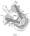
脊髄の損傷又は変形を治す及び/又は安定させるための様々な器具や補綴具(prostheses:プロテーゼ)が提案されている。そのような器具は、人工脊椎円板、核等を含む。該器具は、脊椎の既存の損傷部又は罹患部を交換するために用いられる。しかしながら、脊椎骨を、いかなる動きをも防ぐ又は低減するために、固定することが望ましい又は必須である場合がある。このような固定器具は一般的に、椎弓根に埋め込まれて他の補綴具の固定具として機能する複数の椎弓根ねじを利用する。図1及び図2に、椎体101から延びる椎弓根102a及び102bを有する脊柱分節100を示す。図2は、当技術分野で知られている椎弓根ねじ200の配置を示す。このような椎弓根ねじ200は、椎弓根にねじ込まれるねじ部208と、ロッド206等の他の固定器具にそれぞれ接続する頭部204及び206を有する。
Various instruments and prostheses have been proposed to cure and / or stabilize spinal cord injuries or deformities. Such instruments include artificial spinal discs, nuclei, etc. The device is used to replace an existing injured or affected area of the spine. However, it may be desirable or essential to fix the vertebrae in order to prevent or reduce any movement. Such fixtures typically utilize multiple pedicle screws that are implanted in the pedicle and act as fixtures for other prostheses. 1 and 2 show a
変性脊椎すべり症、峡部脊椎すべり症、減圧後の癒着、脊椎骨折、及び外科手術により修復された脊椎偽関節等の様々な状態の患者に対して脊椎の安定及び脊椎の固定を提供するのに、椎弓根ねじ固定システムが用いられている。剛性椎弓根ねじ/ロッド固定器具の出現により、特に変性円板疾患及び脊椎すべり症の治療のための関節固定術(すなわち、関節固定の外科手術)のスピードが劇的に上がった。関節固定術のスピードが上がったことに加え、剛性器具(rigid instrumentation)の使用は、外科医が脊椎すべり症を即座に保持、改善、又は完全に整復することを可能にし、これらの器具は、減圧術のための非常に積極的な戦略を可能にした。 To provide spinal stability and spinal fixation for patients with various conditions such as degenerative spondylolisthesis, isthmus spondylolisthesis, decompression adhesions, vertebral fractures, and surgically repaired spinal nonunions. , Spondylolisthesis screw fixation system is used. The advent of rigid pedicle screw / rod fixation devices has dramatically increased the speed of arthrodesis (ie, arthrodesis surgery), especially for the treatment of degenerative disc disease and spondylolisthesis. In addition to speeding up arthrodesis, the use of rigid instrumentation allows surgeons to immediately maintain, improve, or completely reduce spondylolisthesis, which decompresses. It enabled a very aggressive strategy for the art.
図2に示すように、当技術分野で知られている一般的な椎弓根ねじ固定システムは、縦方向に相互接続され、椎弓根ねじ200等の椎弓根ねじを用いて隣接する脊椎骨に固定される複数の固体ロッド206からなる多部品デバイス(multi−component devices)である。これらのねじ及びその他の部品は、通常、ステンレス、チタン、又は他の許容できる埋め込み可能な材料、一般的には金属合金からなる。外科医は、これらの部品からいくつかを選び、患者の解剖学的及び生理的要求に適したシステムを構築する。椎弓根ねじは、長骨で用いられるねじと同様のものである。
As shown in FIG. 2, common vertebral pedicle screw fixation systems known in the art are longitudinally interconnected and adjacent vertebrae using pedicle screws such as the
椎弓根ねじは、埋め込み時には、穿設された又は椎弓根102a及び102bのそれぞれの海綿状中心軸を通って形成されたチャネル内に挿入される。縦方向に接続している複数のロッド206は、通常2以上の脊椎骨にわたって設けられ、それらの脊椎骨を固定し、上記のように各ねじ200に接続される。各脊椎骨は、通常、両椎弓根内の椎弓根ねじを受け入れる。接続ロッド206は、脊椎の片側にわたって延びるロッドのそれぞれと対をなして設けられる。
At the time of implantation, the pedicle screw is inserted into a channel formed through the perforated or spongy central axes of the
ねじは、いくつかの機構を通して骨内での食い付きを保持する。引き抜き抵抗の源は、主にねじ山を用いることにより得られる。ねじ山を用いることで、周囲の骨材料との接触面積が増えるため、より強固な固定を得ることができる。なお、当技術分野では、ねじを脊椎骨の正中面に向けて配置すると、ねじと骨材料の接触量が増えるため、引き抜き抵抗を高めることができる。 The screw retains the bite in the bone through several mechanisms. The source of pull-out resistance is mainly obtained by using a thread. By using a screw thread, the contact area with the surrounding bone material is increased, so that stronger fixation can be obtained. In the art, when the screw is arranged toward the median surface of the vertebra, the amount of contact between the screw and the bone material increases, so that the pull-out resistance can be increased.
骨ねじの引き抜きに対する抵抗が不十分なことは、現状の骨ねじに認識されている問題である。この問題は、骨粗しょう症の患者にみられるような骨質が悪い場合に直面される。ねじの骨への固定は、骨とねじ間の接触面積の量及びその接触の質に直接関係している。よって、骨とねじ表面間の直接接触面積が大きいほど、よりよい食い付きと固定が得られる。直径が大きい長いねじは、直径が小さい短いねじよりも、表面接触面積が大きいため、よりよい固定を提供することができる。また、ねじと骨間の実際の接触面は骨密度によって決まる。これは、骨密度が高い骨の方が、骨密度が低い骨よりも、得られるねじ表面と骨材料間の直接接触面積が大きいためである。従って、骨密度が低い骨粗しょう症の患者は、正常な骨密度の患者よりも、ねじと骨間の表面接触面積が小さくなる。 Insufficient resistance to pulling out the bone screw is a perceived problem with current bone screws. This problem is faced with poor bone quality, as seen in patients with osteoporosis. Fixation of a screw to bone is directly related to the amount of contact area between the bone and the screw and the quality of that contact. Therefore, the larger the direct contact area between the bone and the thread surface, the better the bite and fixation. Longer screws with larger diameters have a larger surface contact area than shorter screws with smaller diameters, which can provide better fixation. Also, the actual contact surface between the screw and the bone is determined by the bone density. This is because the bone with high bone density has a larger direct contact area between the obtained screw surface and the bone material than the bone with low bone density. Therefore, patients with osteoporosis with low bone density have a smaller surface contact area between the screw and bone than patients with normal bone density.
ねじに対して常に前後に働くトグルの力によって生じるねじの緩みも、ねじ抜けの原因の1つである。これらの力は、脊椎の通常の屈曲及び伸張運動の間に発生し得る(Chao,C.K. et al. Increasing Bending Strength and Pullout Strength in Conical Pedicle Screws: Biomechanical Tests and Finite Element Analyses. J. Spinal Disorders & Techniques. 2008. 21 (2): 130−138,2008)。 Loosening of a screw caused by the force of a toggle that always acts on the screw back and forth is also one of the causes of screw removal. These forces can occur during normal flexion and extension of the spine (Chao, CK et al. Analyzing Blending Strength and Pullout Muscles in Classical Pedicle Analysis Screws: Biomechanics). Disorders & Technologies. 2008. 21 (2): 130-138, 2008).
既知の椎弓根ねじの例は、米国特許第4,887,596号明細書及び第5,207,678号明細書に記載されている。最近では、更に特定の問題を解決するためのねじ及びねじシステムも提案されている。例えば、米国特許出願公開第2007/0299450号明細書に、カニューレ装着椎弓根ねじが記載されている。この文献では、椎弓根ねじに、中央カニューレ、又は該ねじの遠位端部に開口部を有する管が設けられている。埋め込み後は、カニューレ内及びねじと骨の接合部分内に骨セメントが注入される。 Examples of known pedicle threads are described in US Pat. Nos. 4,887,596 and 5,207,678. Recently, screws and screw systems have also been proposed to solve even more specific problems. For example, US Patent Application Publication No. 2007/0299450 describes a cannula-mounted pedicle screw. In this document, the pedicle screw is provided with a central cannula or a tube with an opening at the distal end of the screw. After implantation, bone cement is injected into the cannula and into the joint between the screw and the bone.
米国特許第7,037,309号明細書には、セルフタッピング遠位端部を有する他のカニューレ装着椎弓根ねじが記載されている。この種のねじは、ねじの挿入前に穴を開ける必要がない。 U.S. Pat. No. 7,037,309 describes another cannulated pedicle screw with a self-tapping distal end. This type of screw does not need to be pierced before inserting the screw.
米国特許出願公開第2005/0182409号明細書及び第2008/0015586号明細書は、脊椎の動的安定化器具を教示しており、椎弓根ねじにかかるせん断応力の問題を対象としている。これらの文献において、器具は、可動素子に接続している頭部が設けられた複数の椎弓根ねじを有している。通常動作の間、これらの素子は圧縮力又は膨張力を吸収するように構成され、それによりねじに伝わる応力の量を減らす。これらの可動素子は、周知のロッドと比較して複雑な素子であることが多い。 U.S. Patent Application Publication Nos. 2005/0182409 and 2008/0015586 teach dynamic stabilization devices for the spine and address the issue of shear stress on vertebral pedicle threads. In these documents, the instrument has a plurality of pedicle threads provided with a head connected to a moving element. During normal operation, these devices are configured to absorb compressive or expansive forces, thereby reducing the amount of stress transmitted to the screw. These movable elements are often more complex than well-known rods.
引き抜き耐性がある骨ねじが求められている。 Bone screws that are resistant to pulling out are required.
本発明は、一態様において、骨ねじ、特に、アンカー部及び該アンカー部に係合するように構成されたねじ付きスリーブ部を備える椎弓根ねじを提供する。アンカー部は、互いに角度をなしている角度付き爪部及びねじ部を有する。ねじ付きスリーブは、雄ねじ及び内部ねじ穴を有する。ねじ付きスリーブは、アンカー部のねじ部に外挿されるように構成されている。ねじ付きスリーブは、ねじ頭部に係合するように構成されているその近位端部に、スリーブ頭部を有する。ねじ頭部は、ロッド等の固定器具に係合するように構成されている。 The present invention provides, in one aspect, a bone thread, particularly a pedicle screw comprising an anchor portion and a threaded sleeve portion configured to engage the anchor portion. The anchor portion has an angled claw portion and a screw portion that are angled with each other. Threaded sleeves have male threads and internal threaded holes. The threaded sleeve is configured to be externally inserted into the threaded portion of the anchor portion. The threaded sleeve has a sleeve head at its proximal end that is configured to engage the screw head. The screw head is configured to engage a fixing device such as a rod.
椎弓根ねじの挿入前に、脊椎骨の椎弓根を通って椎体内に通じるチャネルを形成することにより、椎弓根ねじの配置を容易にしてもよい。従って、椎弓根ねじを挿入することができ、それにより角度付き部が所定位置に押し込まれる。続いて、ねじ付きスリーブをアンカー部のねじ部に外挿し、ねじ頭部をスリーブ頭部上に取り付けることにより、固定器具の装着を容易にする。 Prior to the insertion of the pedicle screw, the placement of the pedicle screw may be facilitated by forming a channel through the vertebral pedicle leading into the vertebral body. Therefore, a pedicle screw can be inserted, which pushes the angled portion into place. Subsequently, the threaded sleeve is externally inserted into the threaded portion of the anchor portion, and the screw head is mounted on the sleeve head, thereby facilitating the attachment of the fixing device.
一態様において、スリーブ頭部及びねじ頭部は、ボール及びソケットジョイントを形成するように互いに係合される。ボール及びソケットジョイントは、ねじ頭部がスリーブ頭部に係合されたまま回転することを可能にする。他の実施形態において、角度付き爪部には、ねじ抜けに耐えるために、脊椎骨内に爪部を押し込むための更なるアンカーとして機能する突出部が設けられている。更なる実施形態において、アンカー部の角度付き部の表面に、周囲の骨材料と接触する爪部の表面積を増やすための薬物処理を施してもよい。これらの表面改質は、更に脊椎骨内に爪部を押し込むためのアンカーとしても機能し得る。このような表面改質は、スタッド及び隆起した突起部を含んでもよい。更なる実施形態において、角度付き部は、骨の成長を促進する穿孔部を有している。そのような骨の成長により、爪部が更に脊椎骨内に係止される。 In one embodiment, the sleeve head and the screw head are engaged with each other to form a ball and socket joint. The ball and socket joints allow the screw head to rotate while being engaged to the sleeve head. In another embodiment, the angled claw is provided with a protrusion that acts as an additional anchor for pushing the claw into the vertebrae to withstand threading. In a further embodiment, the surface of the angled portion of the anchor may be treated with a drug to increase the surface area of the claw in contact with the surrounding bone material. These surface modifications can also serve as anchors for pushing the nail into the vertebrae. Such surface modifications may include studs and raised protrusions. In a further embodiment, the angled portion has a perforation that promotes bone growth. Such bone growth further locks the claws into the vertebrae.
本発明の特徴は、添付の図面を参照してなされる以下の詳細な説明により更に明らかにされる。 The features of the present invention will be further clarified by the following detailed description made with reference to the accompanying drawings.
以下の説明は、様々な実施形態を参照してなされる。該説明は、主に椎弓根ねじ及び脊椎の安定化について言及する。しかしながら、当業者にとって、ここでいうねじはいかなる骨の固定又は固定化用途において及び/又はそのために用いることもできることが理解されよう。従って、ここで言及する椎弓根ねじ及び脊柱固定又は癒合は、本発明の特定の態様を例示するものであり、いかなる方法においても本発明を限定することを意図したものでないことが理解されよう。ここでいう骨ねじは、例えば、大腿骨、脛骨、腓骨、尺骨等の大きな骨に関わる用途や、頸椎に頸部プレート及びケージを取り付けるために用いることができる。従って、ここで「椎弓根ねじ」と言及するものはすべて、椎弓根に固定するために用いられる本発明の一態様による骨ねじであることが理解されよう。また、以下の説明は添付の図面と図示の要素を参照してなされ、それらの要素は1つ又は複数の参照番号により特定されることが理解されよう。特に説明がない限りは、それらの要素のうちいずれの要素の特徴もが、特定のために用いられる参照番号が違っていたとしても同等の要素に当てはまることが理解されよう。 The following description is made with reference to various embodiments. The description primarily refers to pedicle threads and spinal stabilization. However, it will be appreciated by those skilled in the art that the screws herein can be used in and / or for any bone immobilization or immobilization application. Therefore, it will be understood that the vertebral root threads and spinal fixation or fusion referred to herein exemplify a particular aspect of the invention and are not intended to limit the invention in any way. .. The bone screw referred to here can be used, for example, for applications related to large bones such as the femur, tibia, fibula, and ulna, and for attaching a cervical plate and cage to the cervical spine. Therefore, it will be understood that anything referred to herein as a "vertebral pedicle screw" is a bone screw according to one aspect of the invention used to secure to the vertebral pedicle. It will also be appreciated that the following description is made with reference to the accompanying drawings and illustrated elements, which are identified by one or more reference numbers. Unless otherwise stated, it will be understood that the characteristics of any of these elements apply to the equivalent, even if the reference numbers used for identification are different.
本発明において、「遠位」及び「近位」という用語が用いられる。これらの用語は単に便宜上用いられるもので、いかなる方法においても本発明を限定することを意図したものではない。「遠位」という用語は、骨に挿入される本発明のねじの端部に関して用いられる。「近位」という用語は、ねじが挿入される骨の外に延びている該ねじの反対側の端部を示すために用いられる。従って、これらの用語は本発明のねじの骨への配置に関する記述に用いられるものであるが、本発明は使用時のねじのみに限定されるわけではなく、骨と組み合わされたときのねじのみに限定されるわけでもないことが理解されよう。 In the present invention, the terms "distal" and "proximal" are used. These terms are used solely for convenience and are not intended to limit the invention in any way. The term "distal" is used with respect to the end of a screw of the invention that is inserted into the bone. The term "proximal" is used to refer to the opposite end of a screw that extends out of the bone into which the screw is inserted. Therefore, although these terms are used in the description of the placement of the screw in the bone of the present invention, the present invention is not limited to the screw at the time of use, but only the screw when combined with the bone. It will be understood that it is not limited to.
ここでいう「後部」及び「前部」という用語は、人間等の哺乳動物内における脊椎の位置に関して用いられる。なお、これらの用語は単に本発明の骨ねじの説明を容易にするために用いられるものであり、いかなる意味においても該ねじを限定するために用いられるべきでないことが理解されよう。 The terms "rear" and "anterior" are used herein with respect to the position of the spine within a mammal such as a human. It should be understood that these terms are used solely to facilitate the description of the bone screw of the present invention and should not be used to limit the screw in any sense.
当技術分野で知られているように、脊椎は複数の脊椎骨を含んでいる。図1は一般的な脊椎骨100の平面図である。脊椎骨100は、主に海綿質骨103の核からなる椎体101を含む。椎体101の外側部分は、密度が高く、海綿質骨103よりも硬質の皮質骨104である。脊椎骨100の後部は、椎弓根102a及び102bにより椎体101に接続されている。これらの椎弓根は、外側は硬質の皮質骨からなり、内側はより軟質の海綿質骨からなる。
As is known in the art, the spine contains multiple vertebrae. FIG. 1 is a plan view of a
図2は、既知のデザインの椎弓根ねじ200が埋め込まれている隣接する腰椎を示す、脊椎分節の矢状横断立面図である。これらのねじは、それぞれ頭部202及び204を有する。図示のように、椎弓根ねじ200のそれぞれは、椎体101の椎弓根102a及び102bを通って海綿質骨103内に挿入されている。これら2つの椎弓根ねじは、別々の椎体内に挿入されている。これら椎弓根ねじ200の頭部202及び204は、2つの隣接する脊椎骨を安定させるために、ロッド206に接続されている。この安定化は、ねじ及びロッドが頑丈な「締め具」を形成して脊椎骨を所定の位置に保持することにより可能となる。これらの要素の組み合わせにより、複数の脊椎骨間の動きが抑制され、安定性が高まる。
FIG. 2 is a sagittal cross-elevation view of the vertebral segment showing an adjacent lumbar spine in which a
図3から分かるように、従来技術の2つの椎弓根ねじ200a及び200bは、椎体101内部に係合している。図示のように、椎弓根ねじのそれぞれは、各椎弓根102a及び102bを通っている。従来技術の椎弓根ねじ200a及び200bの本体部は、主にそれぞれねじ部300a及び300bからなる。また、これらのねじは、例えば頭部202及び204と接続するために球状であってもよい近位部301a及び302bを有しており、それにより図2に示すようにロッド206への接続が容易になる。
As can be seen from FIG. 3, the two prior
図から分かるように、ねじ200a及び200bは、椎弓根102a及び102bを通って椎体101内に挿入される。これは脊椎骨の解剖学的構造を利用しており、ねじ抜けに耐えられるように、骨と椎弓根ねじ間の接触面積を増やす。
As can be seen from the figure, the
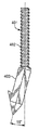
図4A及び4Bに、本発明の一態様による椎弓根ねじ400の部品を示す。椎弓根ねじ400は、アンカー部401とねじ付きスリーブ404を有する。アンカー部401は、遠位の角度付き部又は爪部403と、近位部のねじ部402からなる。近位のねじ部402は、雄ねじを有する軸からなる。図4に示すような一実施形態において、角度付き部又は爪部403は図示の四角断面形状を有するが、以下に説明するような他の断面形状を有してもよい。また、角度付き部又は爪部403は、遠位端部415におけるとがった先端部413等の先端部を有してもよい。先端部413は、好ましくは爪部403を脊椎骨100内に挿入するのを補助するために設けられる。ある実施形態においては、とがった先端部413は省いてもよく、又は同様の機能性を提供する他の構成と入れ替えてもよいことが理解されよう。また、本発明により、爪部は骨ねじのアンカーとしての機能を果たすことが理解されよう。
4A and 4B show the parts of the
角度付き部又は爪部403の縦軸及びねじ部402の縦軸は、互いに角度をなしている。以下に詳述するように、角度付き部又は爪部403とねじ部402の間の角度は、様々な角度であってもよい。
The vertical axis of the angled portion or the
一実施形態における角度付き部又は爪部403には、遠位端部415における突起412を設けてもよい。以下に詳述するように、突起412は、椎弓根ねじ400が脊椎骨100等の骨内に埋め込まれた後、特に骨の再生が起こった後に、固定力を高めるのに役立つ。
The angled portion or the
爪部401のねじ部402は、アンカー部401を安定させるための設定器具を受け入れる凹部414を含んでもよい。該設定器具は、ねじ付きスリーブ404を挿入時に案内するために用いてもよい。図6Bに凹部414の例を示す。ここで、図示の凹部414は六角形状を有している。当然のことながら、凹部414の形状は、設定器具の形状に対応できるようになっている。従って、当然のことながら、凹部414は他のいかなる形状を有してもよい。以下に、アンカー部を安定させる他の手段を図21A〜図21Hを用いて説明する。
The threaded
ねじ付きスリーブ404は、近位端部417と遠位端部418を有する。ねじ付きスリーブは、その外面に雄ねじ406を有し、また、ねじ付きスリーブ404の遠位端部418と近位端部417の間に延びる内部穴405を有する。内部穴405の壁は、ねじ山、ここでいう雌ねじ407によりねじ切り加工されている。雄ねじ406は、ねじ付きスリーブ404の遠位端部418と近位端部417の間に延びている。また、ねじ付きスリーブ404は、スリーブ頭部408に係合されるねじ頭部410を有してもよい。図示の実施形態では、スリーブ頭部408としておよそ球状のものが示されているが、このような形状は、スリーブ頭部408及びねじ頭部410が図10に示すようにボール及びソケットジョイントを形成しているために、特に有利である。このように、本実施形態によるねじ頭部410は、スリーブ頭部408に接続されたまま様々な方向に動くことが可能である。なお、スリーブ頭部408は様々な形状を有してもよいことが理解されよう。
The threaded
他の態様では、ねじ頭部410はスリーブ頭部408の一部として形成されるように、スリーブ404と一体形成されてもよい。他の態様では、ねじ頭部は、ねじが骨内に挿入される前若しくは挿入されている間、又は挿入された後にスリーブ頭部408に接続される独立した部品であってもよい。ねじ頭部410は、例えばスリーブ頭部408上に取り付けられてもよい。例えば、一態様においては、図18に示すようにねじ頭部410aはスリーブ404内に挿入される柱部420を有してもよい。一態様においては、そのような柱部420には、スリーブ404の雌ねじと協働するように構成されている雄ねじが設けられてもよい。頭部410aは、どのように柱部に固定されてもよい。
In another aspect, the
スリーブ頭部408は、ねじ400を脊椎骨100内に配置するのに用いることができる器具を通すための開口部409を含んでもよい。通路1000は、図10に示すように、開口部409と内部ねじ穴405の間に延びる開口チャネルを有している。通路1000は、器具が開口部409を通って内部ねじ穴405に入ることを可能にする。通路1000の半径は、アンカー部401及びねじ付きスリーブ404を脊椎骨100内に配置するのに用いられる器具によって異なってもよい。雌ねじ407は、ねじ部402のねじ山に係合するように構成されている。内部穴405の半径は、雌ねじ407がアンカー部401のねじ部402上にねじ込まれる際に、ねじ部402が穴405に挿入されるのに十分な大きさを有する。好ましい実施形態においては、穴405はアンカー部401のねじ部402の全長を受け入れるように構成されている。
The
ねじ頭部410は、当技術分野で知られているように、頭部410が固定器具に係合することを可能にする凹部411又は他の類似の構成を有する。例えば、固定器具は上記したようなロッド206を有してもよい。本発明は、用いられ得る固定器具の種類に限定されない。同様に、本発明は、ねじ頭部410のいかなる特定の形又は機能にも限定されない。
The
椎弓根ねじ400を脊椎骨100内に挿入する方法を、本発明の一態様に基づいて説明する。通常、ねじ400の脊椎骨内への挿入又は埋め込みは、2段階の手順を有する。第1に、アンカー部401が椎弓根102a又は102bのいずれかの椎弓根を通して椎体101内に挿入される。第2に、ねじ付きスリーブ404が、アンカー部401のねじ部402に外挿されることにより埋め込まれる。当然のことながら、ねじ付きスリーブ404が埋め込まれると、ねじ付きスリーブ404上に設けられた雄ねじが椎弓根骨に係合する。このようにしてねじ400が埋め込まれると、骨が通常の治癒過程においてねじ周りで再生することが可能となる。当然のことながら、そのような骨の再生ステップは脊椎骨内でのねじの保持力を高める。
A method of inserting the
好ましい実施形態においては、アンカー部401の挿入前に、アンカー部401用のチャネルがまず椎弓根及び椎体を通して形成され、少なくともアンカー部401の挿入を容易にするのを助ける。一実施形態において、このようなチャネルは図16に示すような椎弓根プローブ1600等の器具を用いて骨材料を取り除くことにより形成される。この例では、チャネルは、アンカー部401の挿入を可能とするために、椎弓根プローブ1600の遠位端部1601を用いて、通路に沿って脊椎骨100内の骨材料を貫通して取り除く又は掘ることにより形成される。当然のことながら、上記したようなチャネルを形成することは、アンカー部401を脊椎骨100内に挿入するための通路を形成することにより、ねじ400の挿入を容易にする。
In a preferred embodiment, prior to the insertion of the
アンカー部401は、その近位端部416に力を加えて脊椎骨100内に押し込むことにより、脊椎骨100内に挿入される。この力は、例えば、当技術分野で知られている適切な手術用具を用いて近位端部416をハンマーで打ち込むことによって生成することができる。一実施形態において、アンカー部401は椎弓根プローブ1600により形成された通路を通して脊椎骨100内に挿入される。アンカー部401は、椎弓根102a又は102bを通して椎体101内に挿入される。アンカー部401の遠位端部415におけるとがった先端部413は、アンカー部401をチャネルに挿入するのを容易にする。このとがった先端部413の形状は、アンカー部401が直面する抵抗を低減する。脊椎骨100内の骨が修復して新しい骨材料が成長すると、その骨材料は、例えばアンカー部401の角度付き部又は爪部403の周りで成長する。従って、突起412が骨材料に囲まれると、該突起412は角度付き部又は爪部403の他の部分と共に、ねじ400を該骨材料内で更に固定するように作用する。当然のことながら、このような固定化により、アンカー部401の引き抜き力に対する抵抗が高まる。同様に、骨の再生は脊椎骨に露出しているねじ400の様々なねじ表面の周りでも起こり、それにより、ねじの引き抜き抵抗が高まる。骨内でのねじの固定化を更に向上させるために、ねじ部分及び爪部分等に対して様々な化学処理又は他の処理を施してもよい。当然のことながら、アンカー部401及び特に角度付き部又は爪部403は、当該骨ねじのアンカーと呼ぶことができる。
The
アンカー部401が脊椎骨100内に挿入される際に、角度付き部又は爪部403の全てが椎体101内に挿入されない場合は、その大部分が挿入されることが望ましい。ねじ部402は、椎弓根102a又は102bのいずれか等の椎弓根内に収容される。好ましい実施形態においては、ねじ部402はその全体が椎弓根内に挿入されるが、一部が椎弓根の外に延びていてもよい。
When the
上記のように、アンカー部401が椎弓根内及び椎体内に挿入されると、ねじ付きスリーブ404を挿入すること又は埋め込むことができるようになる。ねじ付きスリーブ404は、椎弓根内に挿入され、アンカー部401のねじ部402に外挿される。上記のように、スリーブ404の埋め込み時には、アンカー部401を安定させるために設定器具を用いてもよい。開口部409は、そのような設定器具がねじ付きスリーブ404の近位端部417を通り、通路1000を通って内部穴405に入ることを可能にする。設定器具は、ねじ付きスリーブ404がアンカー部401のねじ部402に外挿されると、アンカー部401の凹部414に係合して、アンカー部401を安定して保持することができる。また、設定器具は、ねじ付きスリーブ404がアンカー部401のねじ部402に外挿される際に、ねじ付きスリーブ404を案内する役割も果たす。一実施形態においては、図11に示すように、スリーブ404上の雄ねじ406とスリーブ頭部408の接合部付近にスロット1100を設けてもよい。スロット1100は、スリーブ404をねじ部402に外挿するのを補助するための他の設定器具に係合するように構成されてもよい。従って、ねじ付きスリーブ404は、スロット1100に係合している器具を用いることにより、アンカー部401に外挿されてもよく、あるいは、スリーブ404は外科医により手動で埋め込まれてもよい。
As described above, when the
上記のように、ねじ付きスリーブ404がアンカー部401に外挿されると、スリーブ404の雄ねじ406は、図16に見られるように椎弓根102b等の椎弓根の骨材料に係合する。該骨材料は、ねじ400に対して椎弓根内での食い付きを提供し、ねじ400と脊椎骨100が接する部分の表面積を増加させる。これらのねじと骨材料の係合は、引き抜き力に対する抵抗を更に高める。
As described above, when the threaded
ねじ付きスリーブ404がねじ部402に外挿された後、ねじ頭部410はスリーブ頭部408に係合することができる。ねじ頭部410は、配置後は、上記したボール及びソケット及びジョイント配置を考慮してスリーブ頭部408の周りを回転することができる。このようにして、ねじ頭部410は、例えばロッド206等の脊椎固定器具に接続できるように適宜配置することができる。当業者に知られているように、ロッド206は2つ以上の脊椎骨にわたる脊椎部分に沿って延び、そのような脊椎領域を安定させるために該脊椎部分に接続される。
After the threaded
当然のことながら、ここでいう椎弓根ねじ400は、既知の椎弓根ねじと同様に骨材料に係合するねじ部を含んでいるが、角度付き部又は爪部403により達成される更なる増強部分をも含み、それにより引き抜き抵抗を高めることができる。上記のように、ここで説明するねじ400により提供される引き抜き抵抗は、突起412を設けることにより更に高めることができる。
As a matter of course, the
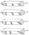
当然のことながら、本発明は、アンカー部401のいかなる特定の角度構成にも限定されない。例えば、図5A〜図5Cに示す様々な別の配置を採用してもよい。図5A〜図5Cに示す角度付き部又は爪部403とねじ部402の間の角度は、15°、30°、及び45°である。本発明はアンカー部401のいかなる特定の角度にも限定されない。
As a matter of course, the present invention is not limited to any particular angular configuration of the
本発明のねじ400は、更に引き抜き抵抗を高めるために変形することができる。例えば、図6A及び6Bに示すように、アンカー部401の角度付き部又は爪部403bに、角度付き部又は爪部403bの本体部分に沿って配置された1列以上の隆起した突起部又はくぎ等600を設けることができる。当然のことながら、突起部又はくぎは、特に一旦骨の再生が起こった後に骨内部においてアンカー部401の固定を更に強化するのに役立つ。図6A、図6B及び図6Cに示す実施形態において、隆起した突起部又はくぎは通常角錐形状である。しかしながら、他の様々な形状をもとり得る。
The
図6Cは、図6AのB−B線に沿った角度付き部又は爪部403bの断面の例を示す。六角形の断面601a、五角形の断面601b、正方形若しくは長方形の断面601c、又は三角形の断面601dは、アンカー部401の異なる実施形態である。本発明は、角度付き部又は爪部403のいかなる特定の断面形状にも限定されない。
FIG. 6C shows an example of a cross section of the angled portion or the
図7A及び7Bは、図6A及び6Bに示すくぎに代わる例を示す。この場合、アンカー部401は、1列以上の目盛り700が設けられた角度付き部又は爪部403cを有する。図から分かるように、目盛りは半径方向外向き、及び、爪部の遠位端部とは離れた近位方向に突き出ている。
7A and 7B show examples of alternatives to the nails shown in FIGS. 6A and 6B. In this case, the
図7Cは、角度付き部又は爪部403cの線C−Cに沿った断面を示す。六角形の断面701a、五角形の断面701b、正方形若しくは長方形の断面701c、又は三角形の断面701dは、角度付き部又は爪部403cがとり得る断面の他のすべての実施形態である。
FIG. 7C shows a cross section of the angled portion or the
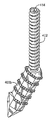
図8A及び図8Bは、本発明のねじの引き抜き抵抗を高めるための更なる別の実施形態を示す。本実施形態では、爪部の角度付き部又は爪部403dには、上記したような1列以上の突起部又はくぎ等800が設けられている。図8A及び8Bの角度付き部又は爪部403dには、更に1つ以上の穿孔部801が設けられている。穿孔部は、角度付き部又は爪部403dの内腔に通じる開口部を有し、この内腔に向かって骨が成長することを可能とされる。当然のことながら、穿孔部に向けて骨が内部成長することにより、脊椎骨100内のアンカー部401の把持力が更に高まる。
8A and 8B show yet another embodiment for increasing the pull-out resistance of the screw of the present invention. In the present embodiment, the angled portion of the claw portion or the
図8Cは、角度付き部又は爪部403dの線D−Dに沿った、該角度付き部又は爪部403dがとり得る六角形802a、五角形802b、正方形802c及び三角形802dの断面の様々な実施形態を示す。角度付き部又は爪部403dの形状はこれらの形状に限定されない。穿孔部801の方向も、骨の内部成長を促進する目的によって異なり得る。801aは、六角形の断面における穿孔部を示し、801bは五角形の断面における穿孔部を示し、801cは四角形の断面における穿孔部を示し、801dは三角形の断面における穿孔部を示す。穿孔部801間の接続もまた、深さ、数及び方向によって可変であり、骨の内部成長を更に容易にするため、及び、引き抜き抵抗を更に高めるために変更してもよい。
FIG. 8C shows various embodiments of the cross sections of the
ここで説明するねじの他の実施形態を図9A及び図9Bに示す。図9A及び図9Bにおいて、アンカー部401は、「フック」形状を形成するように湾曲した角度付き部又は爪部403eが設けられている。なお、図9A及び図9Bの角度付き部又は爪部403eの表面は、必要に応じて上記のようにくぎ、目盛り、及び/又は穿孔部を含むように変形してもよい。
Other embodiments of the screws described herein are shown in FIGS. 9A and 9B. In FIGS. 9A and 9B, the
図9Cに示すように、角度付き部又は爪部403eは、角度付き部又は爪部403eの線E−Eを横切る様々な断面を有することができる。角度付き部又は爪部403eの断面形状は、様々な実施形態として、六角形の断面901a、五角形の断面901b、四角形若しくは長方形の断面901c、又は三角形の断面901dのいずれであってもよい。
As shown in FIG. 9C, the angled portion or
図14及び図15は、脊椎骨100に埋め込まれた一実施形態による椎弓根ねじ400を示す。これらの図は、椎弓根ねじ200等の既知の椎弓根ねじと比較して、本発明のねじがどのように骨材料を捕獲するかの違いを示している。
14 and 15 show the
ねじ付きスリーブ404の雄ねじ406は、椎弓根1bの骨材料と共に食い付きを提供することもできる。突起412を設けると、脊椎骨100の骨材料への固定具として機能し、また、引き抜き抵抗が高まる。つまり、当技術分野で知られている図示の椎弓根ねじ200は、椎弓根102aをまっすぐ貫通して椎体内101に入っているが、本発明の実施形態による図示のねじ400は、その角度付き部又は爪部403及びねじ部402が椎体101及び椎弓根102bと係合している。図から分かるように、ねじ400は、既知のねじ200よりも多くの骨材料に接触して該骨材料を把持している。
The
上記の通り、少なくともねじ400のアンカー部401が挿入される又は埋め込まれるチャネルを形成するために、図16A及び16Bに示す椎弓根プローブ1600等の器具を用いてもよい。椎弓根及び椎体101から骨材料を掘り出すために、プローブ1600を脊椎骨内に挿入して押し込む。プローブ1600は、角度付遠位部1601、中央部1602、及び近位部1603を有する。図示の通り、遠位部1601は好ましくは器具の他の部分に対して角度を有している。当然のことながら、このような角度を設けることにより、上記のチャネルを、アンカー部401の角度付き部を収容できるように形成することができる。
As described above, instruments such as the
図17A〜図17Cに示す通り、椎弓根プローブ1600は、遠位部1601と中央部1602の間にいかなる角度を有してもよい。当然のことながら、ねじ400の角度付き部401に設けられる角度に応じて、所望の椎弓根プローブを選択してもよい。
As shown in FIGS. 17A-17C, the
当該骨ねじの他の実施形態を図19及び図20に示す。図19及び図20において、上記の要素と同様のものは同様の参照番号で示すが、説明を分かりやすくするために「b」の文字を付した。図示の通り、骨ねじ400bは、スリーブ404b及び固定(又は爪)部401bを有する。上記の通り、アンカー部401bは、骨内に形成される空洞に挿入されるように構成されている。アンカー部401bは、角度付き部又は爪部403bを含む。本実施形態において、角度付き部又は爪部403bは、概して平坦な第1の面430、及び、溝又はセレーションを含む反対側の第2の面432を含む。当然のことながら、溝又はセレーションは、アンカー部401bを骨内に固定するのを補助する役割を果たす。具体的には、骨の成長が起こると、新たな骨材料がセレーションの内部に向けて成長し、それによりアンカー部を固定する。図19及び図20に示す実施形態では、角度付き部又は爪部403bの外面の一部に、任意で表面仕上げを施してもよい。このような構成は、ねじ、特にアンカー部401bを抜き出す必要がある場合に役立つ。そのような場合、セレーションのみを周囲の骨から抜き出すことにより、アンカー部401bの除去を容易にする必要がある。なお、セレーションは、任意で角度付き部又は爪部403bの全面に設けてもよいし、全く設けなくてもよい。後者の場合、必要に応じて角度付き部又は爪部403bに他の骨粘着仕上げ又は処理を施してもよい。
Other embodiments of the bone screw are shown in FIGS. 19 and 20. In FIGS. 19 and 20, similar elements to the above are indicated by similar reference numbers, but with the letter "b" for clarity. As shown, the
図19及び図20に示すスリーブ404bは、上記のものと同様である。具体的には、図20に示すように、スリーブ404bは、少なくともアンカー部401bの近位端部を受け入れるように構成された内部穴を含む。上記の通り、アンカー部401bの近位端部に隣接する部分は、スリーブ404bの内部穴に受け入れられる。上記の通り、スリーブ404bの内部穴と、アンカー部401bの該内部穴に受け入れられる部分の外面は、互いに共同するねじ山が設けられており、それによりスリーブ404bをアンカー部に外挿することができる。スリーブ404bの遠位部の外面は、当該骨内にねじ込まれるのに適したねじ切り406bが設けられている。
The
骨ねじの他の実施形態を図21A〜図21Hに示す。図21A〜図21Hも、骨ねじシステムの他の実施形態を示す。これらの図において、上記の要素と同様のものは同様の参照番号で示すが、説明を簡単にするために「c」の文字を付した。更に、図21A〜図21Hに示すアンカー部401cは、上記のアンカー部401bと同様のものである。以下に、図21A〜図21Hの実施形態を、骨への埋め込み方法の観点から説明する。図21Aは、骨ねじの埋め込みを補助するために用いられる挿入器具500を示す。挿入器具500は、近位端部502と遠位端部504を有する、細長いプローブ状構造を有する。挿入装置の少なくとも遠位端部504と隣接する部分には、506で示すねじ外面が設けられている。本実施形態の方法では、外側スリーブ404cは挿入器具500と組み合わされる。図21Bに示すように、挿入器具500は、頭部410c及びスリーブ404cの穴を通して挿入される。具体的には、挿入器具の遠位端部504は、頭部410c及びスリーブ404cの近位端部を通して挿入され、スリーブ404cの遠位端部を通って突き出ることを可能とされる。
Other embodiments of the bone screw are shown in FIGS. 21A-21H. 21A-21H also show other embodiments of the bone screw system. In these figures, similar elements to the above are indicated by similar reference numbers, but with the letter "c" for simplicity. Further, the
本実施形態では、挿入器具500の遠位端部504は、プローブ先端部508と、ねじ山506の遠位端部を形成する第1の接続部510が設けられている。図21Cに示すように、アンカー部401cの近位端部416cは、第2の接続部512を含む。第1及び第2の接続部510、512は、互いに係合されるように構成されている。例えば、図示の実施形態では、第1の接続部510は1対のつまみを含み、第2の接続部512は対応する1対のスロットを含み、これらのスロットは第1の接続部510のつまみを受け入れるように構成されている。なお、下記の目的のために他の接続形態を用いてもよいことが理解されよう。
In this embodiment, the
図21Dは、組み合わされたとき、つまり第1及び第2の接続部が互いに係合されたときのアンカー部401c及び挿入器具500を示している。
FIG. 21D shows the
図21Eに示すように、挿入器具500がアンカー部401cに係合されると、スリーブ404cが挿入器具から滑り落とされ、(後述する)スリーブ404cの内部穴に設けられたねじ山が、アンカー部401cのねじ部402cに設けられたねじ山に係合することを可能とされる。このようなスリーブ404cとアンカー部401cの係合は、上記の構成と同様である。そして、スリーブ404cは上記と同様にアンカー部401cに外挿される。本発明から明らかな通り、スリーブ404cを回してアンカー部401cに固定するための手段は、いかなるものを用いてもよい。図21Fは、スリーブ404cが完全にアンカー部401cに外挿された後のシステムを示す。当然のことながら、スリーブ404cをアンカー部401cに固定するステップの間、挿入器具500を用いてアンカー部401cを保持及び安定させることができる。この点に関して、図21Gは、上記の手順の間、挿入器具500を保持するのに用いてもよい任意の取っ手514を示す。スリーブ404cがアンカー部401cに固定された後は、挿入器具500は第1及び第2の接続部の係合を解除することによって取り除かれてもよい。
As shown in FIG. 21E, when the
図21Hは、本実施形態による骨ねじ400cが埋め込まれて挿入器具が取り除かれた後の、組立骨ねじ400cを示す。図示の通り、当然のことながら、アンカー部401cの角度付き部又は爪部403c及びスリーブ404cのねじ部406cは、骨材料(図示せず)に露出している。
FIG. 21H shows the assembled bone screw 400c after the bone screw 400c according to the present embodiment has been embedded and the insertion device has been removed. As shown, as a matter of course, the angled portion of the
上記の説明から理解されるように、本発明の骨ねじは、該骨ねじの骨材料への埋め込み固定を強化することにより、既知のねじに対し改良を提供するものである。 As can be understood from the above description, the bone screw of the present invention provides an improvement over a known screw by strengthening the implantation and fixation of the bone screw to the bone material.
本発明のねじ及びねじ部品は、当業者に知られているいかなる材料からも形成することができる。例えば、ねじの要素は、ステンレス、チタン、チタン合金、ニッケルチタン合金(例えばNitinol(登録商標))、コバルトクロム合金等の金属又は金属合金、プラスチック及び/又は熱可塑性ポリマー(例えばPEEK(登録商標))、カーボンファイバー、若しくは他のいかなる材料、又は、一般的に骨ねじ材料と関連している材料の組み合わせからも形成することができる。なお、本発明のねじ及びねじ部品の表面は、骨内の配置又は接着を向上するため又は骨の成長を促進するために、任意で他の既知の物質でコーティングされてもよい。例えば、一実施形態において、ねじの外面、又は、少なくとも埋め込み後に骨と接触するねじの外面部分は、ねじのオッセオインテグレーションを促進するために、ヒドロキシアパタイトでコーティングされ、それによりねじの引き抜き抵抗が高められてもよい。 The screws and threaded parts of the present invention can be formed from any material known to those of skill in the art. For example, the screw elements are metals or metal alloys such as stainless steel, titanium, titanium alloys, nickel titanium alloys (eg Nitinol®), cobalt-chromium alloys, plastics and / or thermoplastic polymers (eg PEEK®). ), Carbon fiber, or any other material, or a combination of materials commonly associated with osteoskin materials. The surfaces of the screws and threaded parts of the present invention may optionally be coated with other known substances in order to improve placement or adhesion within the bone or to promote bone growth. For example, in one embodiment, the outer surface of the screw, or at least the outer surface of the screw that comes into contact with the bone after implantation, is coated with hydroxyapatite to facilitate osseointegration of the screw, thereby reducing the pull-out resistance of the screw. It may be enhanced.
なお、上記の説明は特定の具体的な実施形態の参照を含むが、当業者にとってその様々な変形例が明らかであろう。上記に挙げた例は、単に例示を目的としたものであり、いかなる方法においても限定を意図したものではない。添付した図面も、単に本発明の様々な態様を例示することを目的としたものであり、いかなる方法においても拡大解釈又は限定解釈を意図したものではない。添付の請求項の範囲も、上記に記載の好ましい実施態様により限定されるべきでなく、概して本明細書と一致した最も広範な解釈を与えられるべきである。ここに引用したすべての従来技術は、その開示内容全体が参照により本明細書に組み込まれる。
It should be noted that the above description includes references to specific specific embodiments, but various modifications thereof will be apparent to those skilled in the art. The examples given above are for illustrative purposes only and are not intended to be limiting in any way. The accompanying drawings are also merely intended to illustrate various aspects of the invention and are not intended to be an expanded or limited interpretation in any way. The scope of the appended claims should not be limited by the preferred embodiments described above and should be given the broadest interpretation generally consistent with this specification. All prior art cited herein are incorporated herein by reference in their entirety.
Claims (15)
b)第1及び第2の端部と内部を貫通して延びる穴とを有する、概して円筒形のスリーブ部材であって、該穴は少なくとも該第2の端部に隣接する部分においてねじ切り加工され、該スリーブ部材は少なくとも該第2の端部に隣接するねじ外面を含み、該ねじ外面は骨内に固定されるように構成されているスリーブ部材と、を備える骨ねじであって、
前記スリーブ部材の前記第2の端部は、前記アンカー部材の前記第1の端部を受け入れるように構成され、前記アンカー部材の前記ねじ部の前記雄ねじは、前記スリーブ部材の前記ねじ切り加工された穴のねじに係合するように構成され、
前記アンカー部材の前記爪部及び前記ねじ部は、それぞれ縦軸を有し、前記爪部の前記縦軸は、前記ねじ部の前記縦軸に対して角度をなすように構成されている骨ねじ。 a) An anchor member having first and second ends and including a claw portion adjacent to the second end portion and a threaded portion having a male screw adjacent to the first end portion. Anchor members configured so that the claw portion and the threaded portion are inserted into the bone,
b) A generally cylindrical sleeve member having first and second ends and holes extending through the interior, the holes being threaded at least in a portion adjacent to the second end. A bone screw comprising a sleeve member comprising at least an outer surface of a screw adjacent to the second end, the outer surface of the screw being configured to be anchored in the bone.
The second end of the sleeve member is configured to receive the first end of the anchor member, and the male thread of the threaded portion of the anchor member is threaded. Configured to engage the screw in the hole
The claw portion and the threaded portion of the anchor member each have a vertical axis, and the vertical axis of the claw portion is configured to be an angle with respect to the vertical axis of the threaded portion. ..
Applications Claiming Priority (3)
| Application Number | Priority Date | Filing Date | Title |
|---|---|---|---|
| US201462092740P | 2014-12-16 | 2014-12-16 | |
| US62/092,740 | 2014-12-16 | ||
| PCT/US2015/066194 WO2016100570A1 (en) | 2014-12-16 | 2015-12-16 | Bone screw |
Publications (3)
| Publication Number | Publication Date |
|---|---|
| JP2017538546A JP2017538546A (en) | 2017-12-28 |
| JP2017538546A5 JP2017538546A5 (en) | 2019-01-31 |
| JP6864620B2 true JP6864620B2 (en) | 2021-04-28 |
Family
ID=56127562
Family Applications (1)
| Application Number | Title | Priority Date | Filing Date |
|---|---|---|---|
| JP2017533386A Active JP6864620B2 (en) | 2014-12-16 | 2015-12-16 | Bone screw |
Country Status (10)
| Country | Link |
|---|---|
| US (1) | US10327819B2 (en) |
| EP (1) | EP3232959B1 (en) |
| JP (1) | JP6864620B2 (en) |
| KR (1) | KR102594552B1 (en) |
| CN (1) | CN107106212B (en) |
| AU (1) | AU2015364631C1 (en) |
| CA (1) | CA2971412A1 (en) |
| DK (1) | DK3232959T3 (en) |
| ES (1) | ES2918002T3 (en) |
| WO (1) | WO2016100570A1 (en) |
Families Citing this family (7)
| Publication number | Priority date | Publication date | Assignee | Title |
|---|---|---|---|---|
| EP3524181B1 (en) | 2018-02-09 | 2021-11-10 | Biedermann Technologies GmbH & Co. KG | System of a bone anchor and an elongate instrument |
| CN109223155B (en) * | 2018-10-29 | 2024-06-04 | 广东健齿生物科技有限公司 | Locking titanium plate internal fixation device |
| US11877934B2 (en) * | 2020-04-07 | 2024-01-23 | Globus Medical, Inc. | Pedicle-based intradiscal fixation devices and methods |
| US11534309B1 (en) * | 2021-07-20 | 2022-12-27 | Globus Medical Inc. | Interlaminar lumbar interbody fusion implants, intradiscal implants, instruments, and methods |
| US20230023449A1 (en) * | 2021-07-20 | 2023-01-26 | Globus Medical, Inc. | Interlaminar lumbar interbody fusion system and associated robotic systems |
| KR102689316B1 (en) * | 2022-01-26 | 2024-07-30 | 주식회사 에어스 | Push-type uni-cortical bone fixation anchor |
| KR102689304B1 (en) * | 2022-01-26 | 2024-07-30 | 주식회사 에어스 | Pull-type uni-cortical bone fixation anchor |
Family Cites Families (15)
| Publication number | Priority date | Publication date | Assignee | Title |
|---|---|---|---|---|
| US4790303A (en) * | 1987-03-11 | 1988-12-13 | Acromed Corporation | Apparatus and method for securing bone graft |
| US4887596A (en) | 1988-03-02 | 1989-12-19 | Synthes (U.S.A.) | Open backed pedicle screw |
| DE3923996A1 (en) | 1989-07-20 | 1991-01-31 | Lutz Biedermann | RECORDING PART FOR JOINTLY CONNECTING TO A SCREW FOR MAKING A PEDICLE SCREW |
| CN2309804Y (en) * | 1997-11-21 | 1999-03-10 | 兰州记忆合金有限公司 | U-shape nail with self-fastening function |
| CA2390912C (en) | 2001-07-05 | 2008-01-29 | Depuy France | Self-tapping screw for small-bone surgery |
| US20050143735A1 (en) * | 2003-04-29 | 2005-06-30 | Kyle Richard F. | Double compression unloadable screw system |
| US7635379B2 (en) | 2003-05-02 | 2009-12-22 | Applied Spine Technologies, Inc. | Pedicle screw assembly with bearing surfaces |
| CN2652344Y (en) * | 2003-10-15 | 2004-11-03 | 孙明林 | Pull up screw for vertebral body olisthy reposition |
| WO2006070961A2 (en) | 2004-12-31 | 2006-07-06 | Ji-Hoon Her | Pedicle screw and device for injecting bone cement into bone |
| DE602007013910D1 (en) | 2006-06-07 | 2011-05-26 | Disc Motion Technologies Inc | pedicle screw |
| AU2009239515B2 (en) * | 2008-04-21 | 2015-07-16 | Total Connect Spine, Llc | Posterior spinal fastener |
| US10631994B2 (en) * | 2012-10-12 | 2020-04-28 | Smith & Nephew, Inc. | Fusion Implant |
| EP2732783B1 (en) | 2012-11-14 | 2016-04-27 | Biedermann Technologies GmbH & Co. KG | Bone nail for the heel |
| CN203176123U (en) * | 2013-04-27 | 2013-09-04 | 浙江捷能汽车零部件有限公司 | Master pin limit screw for front axle and front shaft |
| US9579123B2 (en) | 2014-09-19 | 2017-02-28 | Globus Medical, Inc. | Orthopedic stabilization devices and methods for installation thereof |
-
2015
- 2015-12-16 KR KR1020177018956A patent/KR102594552B1/en active IP Right Grant
- 2015-12-16 CN CN201580068920.XA patent/CN107106212B/en active Active
- 2015-12-16 JP JP2017533386A patent/JP6864620B2/en active Active
- 2015-12-16 AU AU2015364631A patent/AU2015364631C1/en active Active
- 2015-12-16 ES ES15871023T patent/ES2918002T3/en active Active
- 2015-12-16 US US15/535,783 patent/US10327819B2/en active Active
- 2015-12-16 DK DK15871023.6T patent/DK3232959T3/en active
- 2015-12-16 CA CA2971412A patent/CA2971412A1/en not_active Abandoned
- 2015-12-16 EP EP15871023.6A patent/EP3232959B1/en active Active
- 2015-12-16 WO PCT/US2015/066194 patent/WO2016100570A1/en active Application Filing
Also Published As
| Publication number | Publication date |
|---|---|
| AU2015364631A1 (en) | 2017-07-06 |
| AU2015364631C1 (en) | 2019-12-12 |
| EP3232959A4 (en) | 2018-08-22 |
| KR102594552B1 (en) | 2023-10-26 |
| US20170360480A1 (en) | 2017-12-21 |
| CN107106212A (en) | 2017-08-29 |
| KR20170095931A (en) | 2017-08-23 |
| EP3232959B1 (en) | 2022-04-27 |
| CA2971412A1 (en) | 2016-06-23 |
| EP3232959A1 (en) | 2017-10-25 |
| JP2017538546A (en) | 2017-12-28 |
| DK3232959T3 (en) | 2022-05-30 |
| US10327819B2 (en) | 2019-06-25 |
| CN107106212B (en) | 2020-11-20 |
| AU2015364631B2 (en) | 2019-09-12 |
| ES2918002T3 (en) | 2022-07-13 |
| WO2016100570A1 (en) | 2016-06-23 |
Similar Documents
| Publication | Publication Date | Title |
|---|---|---|
| JP6864620B2 (en) | Bone screw | |
| US11369419B2 (en) | Implants for spinal fixation and or fusion | |
| US9936983B2 (en) | Implants for spinal fixation or fusion | |
| JP2022520101A (en) | Implants for spinal fixation and / or fusion | |
| US8951295B2 (en) | Posterior spinal fastener | |
| US7060066B2 (en) | Spinal fixation support device and methods of using | |
| US9636158B2 (en) | Pedicle screw with reverse spiral cut and methods thereof | |
| US20120184993A1 (en) | Expandable facet screw | |
| US20120010668A1 (en) | Expandable surgical implant | |
| CN112533553B (en) | Spinal implant systems and methods | |
| US20070055236A1 (en) | Translaminar facet augmentation and flexible spinal stabilization | |
| JP2004535879A (en) | Bone implantation device | |
| US9675384B2 (en) | Spinal stabilization system | |
| US10368923B2 (en) | Bone fixation system | |
| US20130041412A1 (en) | Flexible pedicle screws | |
| US20120158066A1 (en) | Adjustable cervical plate | |
| JP2018519977A (en) | Bone element fixation implant | |
| US9326777B2 (en) | Decorticating surgical instruments and guidance systems with tactile feedback | |
| US11571196B2 (en) | Surgical system | |
| US20200022734A1 (en) | Apparatus, system, and method for spinal vertebrae stabilization | |
| CN113164194A (en) | Surgical implant and method of use |
Legal Events
| Date | Code | Title | Description |
|---|---|---|---|
| A529 | Written submission of copy of amendment under article 34 pct |
Free format text: JAPANESE INTERMEDIATE CODE: A529 Effective date: 20170726 |
|
| RD01 | Notification of change of attorney |
Free format text: JAPANESE INTERMEDIATE CODE: A7426 Effective date: 20181019 |
|
| A521 | Request for written amendment filed |
Free format text: JAPANESE INTERMEDIATE CODE: A821 Effective date: 20181019 |
|
| A521 | Request for written amendment filed |
Free format text: JAPANESE INTERMEDIATE CODE: A523 Effective date: 20181213 |
|
| A621 | Written request for application examination |
Free format text: JAPANESE INTERMEDIATE CODE: A621 Effective date: 20181213 |
|
| A131 | Notification of reasons for refusal |
Free format text: JAPANESE INTERMEDIATE CODE: A131 Effective date: 20191119 |
|
| A977 | Report on retrieval |
Free format text: JAPANESE INTERMEDIATE CODE: A971007 Effective date: 20191115 |
|
| A601 | Written request for extension of time |
Free format text: JAPANESE INTERMEDIATE CODE: A601 Effective date: 20200206 |
|
| A521 | Request for written amendment filed |
Free format text: JAPANESE INTERMEDIATE CODE: A523 Effective date: 20200518 |
|
| A02 | Decision of refusal |
Free format text: JAPANESE INTERMEDIATE CODE: A02 Effective date: 20201020 |
|
| A521 | Request for written amendment filed |
Free format text: JAPANESE INTERMEDIATE CODE: A523 Effective date: 20210219 |
|
| C60 | Trial request (containing other claim documents, opposition documents) |
Free format text: JAPANESE INTERMEDIATE CODE: C60 Effective date: 20210219 |
|
| A911 | Transfer to examiner for re-examination before appeal (zenchi) |
Free format text: JAPANESE INTERMEDIATE CODE: A911 Effective date: 20210226 |
|
| C21 | Notice of transfer of a case for reconsideration by examiners before appeal proceedings |
Free format text: JAPANESE INTERMEDIATE CODE: C21 Effective date: 20210302 |
|
| TRDD | Decision of grant or rejection written | ||
| A01 | Written decision to grant a patent or to grant a registration (utility model) |
Free format text: JAPANESE INTERMEDIATE CODE: A01 Effective date: 20210323 |
|
| A61 | First payment of annual fees (during grant procedure) |
Free format text: JAPANESE INTERMEDIATE CODE: A61 Effective date: 20210402 |
|
| R150 | Certificate of patent or registration of utility model |
Ref document number: 6864620 Country of ref document: JP Free format text: JAPANESE INTERMEDIATE CODE: R150 |
|
| S111 | Request for change of ownership or part of ownership |
Free format text: JAPANESE INTERMEDIATE CODE: R313113 |
|
| S531 | Written request for registration of change of domicile |
Free format text: JAPANESE INTERMEDIATE CODE: R313531 |
|
| R350 | Written notification of registration of transfer |
Free format text: JAPANESE INTERMEDIATE CODE: R350 |
|
| R250 | Receipt of annual fees |
Free format text: JAPANESE INTERMEDIATE CODE: R250 |