JP6861492B2 - Disposable diapers - Google Patents
Disposable diapers Download PDFInfo
- Publication number
- JP6861492B2 JP6861492B2 JP2016192294A JP2016192294A JP6861492B2 JP 6861492 B2 JP6861492 B2 JP 6861492B2 JP 2016192294 A JP2016192294 A JP 2016192294A JP 2016192294 A JP2016192294 A JP 2016192294A JP 6861492 B2 JP6861492 B2 JP 6861492B2
- Authority
- JP
- Japan
- Prior art keywords
- width direction
- engaging pin
- sheet
- disposable diaper
- body sheet
- Prior art date
- Legal status (The legal status is an assumption and is not a legal conclusion. Google has not performed a legal analysis and makes no representation as to the accuracy of the status listed.)
- Active
Links
- 238000005452 bending Methods 0.000 claims description 31
- 239000006096 absorbing agent Substances 0.000 claims description 13
- 239000004745 nonwoven fabric Substances 0.000 claims description 13
- 238000000034 method Methods 0.000 description 11
- 239000000835 fiber Substances 0.000 description 9
- -1 polyethylene Polymers 0.000 description 9
- 239000004698 Polyethylene Substances 0.000 description 5
- 230000000694 effects Effects 0.000 description 5
- 229920000573 polyethylene Polymers 0.000 description 5
- 239000004743 Polypropylene Substances 0.000 description 4
- 230000015572 biosynthetic process Effects 0.000 description 4
- 230000037237 body shape Effects 0.000 description 4
- 229920001155 polypropylene Polymers 0.000 description 4
- 238000007789 sealing Methods 0.000 description 4
- 150000001336 alkenes Chemical class 0.000 description 3
- 229920001971 elastomer Polymers 0.000 description 3
- 239000000463 material Substances 0.000 description 3
- JRZJOMJEPLMPRA-UHFFFAOYSA-N olefin Natural products CCCCCCCC=C JRZJOMJEPLMPRA-UHFFFAOYSA-N 0.000 description 3
- 229920000728 polyester Polymers 0.000 description 3
- 238000003672 processing method Methods 0.000 description 3
- 239000005060 rubber Substances 0.000 description 3
- 229920000742 Cotton Polymers 0.000 description 2
- 229920000297 Rayon Polymers 0.000 description 2
- XUIMIQQOPSSXEZ-UHFFFAOYSA-N Silicon Chemical compound [Si] XUIMIQQOPSSXEZ-UHFFFAOYSA-N 0.000 description 2
- PPBRXRYQALVLMV-UHFFFAOYSA-N Styrene Chemical compound C=CC1=CC=CC=C1 PPBRXRYQALVLMV-UHFFFAOYSA-N 0.000 description 2
- 230000002745 absorbent Effects 0.000 description 2
- 239000002250 absorbent Substances 0.000 description 2
- 230000002093 peripheral effect Effects 0.000 description 2
- 239000002985 plastic film Substances 0.000 description 2
- 229920000642 polymer Polymers 0.000 description 2
- 239000002964 rayon Substances 0.000 description 2
- 239000005871 repellent Substances 0.000 description 2
- 239000010703 silicon Substances 0.000 description 2
- 229910052710 silicon Inorganic materials 0.000 description 2
- 229920002994 synthetic fiber Polymers 0.000 description 2
- 239000012209 synthetic fiber Substances 0.000 description 2
- 210000002700 urine Anatomy 0.000 description 2
- 239000004831 Hot glue Substances 0.000 description 1
- 239000004793 Polystyrene Substances 0.000 description 1
- 239000002174 Styrene-butadiene Substances 0.000 description 1
- 229920006311 Urethane elastomer Polymers 0.000 description 1
- 150000001408 amides Chemical class 0.000 description 1
- MTAZNLWOLGHBHU-UHFFFAOYSA-N butadiene-styrene rubber Chemical compound C=CC=C.C=CC1=CC=CC=C1 MTAZNLWOLGHBHU-UHFFFAOYSA-N 0.000 description 1
- 229920002301 cellulose acetate Polymers 0.000 description 1
- 150000002148 esters Chemical class 0.000 description 1
- 239000011256 inorganic filler Substances 0.000 description 1
- 229910003475 inorganic filler Inorganic materials 0.000 description 1
- 238000004898 kneading Methods 0.000 description 1
- 239000000155 melt Substances 0.000 description 1
- 239000002184 metal Substances 0.000 description 1
- 239000012188 paraffin wax Substances 0.000 description 1
- 230000035699 permeability Effects 0.000 description 1
- 229920002647 polyamide Polymers 0.000 description 1
- 229920005672 polyolefin resin Polymers 0.000 description 1
- 229920002223 polystyrene Polymers 0.000 description 1
- 229920002635 polyurethane Polymers 0.000 description 1
- 239000004814 polyurethane Substances 0.000 description 1
- 238000003825 pressing Methods 0.000 description 1
- 238000004080 punching Methods 0.000 description 1
- 230000002940 repellent Effects 0.000 description 1
- 239000011115 styrene butadiene Substances 0.000 description 1
- 229920003048 styrene butadiene rubber Polymers 0.000 description 1
- XLYOFNOQVPJJNP-UHFFFAOYSA-N water Substances O XLYOFNOQVPJJNP-UHFFFAOYSA-N 0.000 description 1
Images


Landscapes
- Absorbent Articles And Supports Therefor (AREA)
- Orthopedics, Nursing, And Contraception (AREA)
Description
本発明は、使い捨ておむつに関するものであり、特に、外観性に優れ、装着者の体形に合わせて使い捨ておむつのウエスト開口と脚開口のサイズを調整できる使い捨ておむつに関するものである。 The present invention relates to a disposable diaper, and more particularly to a disposable diaper which has excellent appearance and can adjust the size of the waist opening and the leg opening of the disposable diaper according to the body shape of the wearer.
従来、使い捨ておむつの外装体の前身頃シートのサイドシール部の外面に係合部を設け、外装体の前身頃シートに被係合部を設け、係合部と被係合部を係合させて使い捨ておむつのサイズを調整する構成が知られている。(特許文献1)
また、使い捨ておむつの外装体の前身頃シートのサイドシール部と、後身頃シートのサイドシール部を分離して形成し、前身頃シートのサイドシール部の内面に係合部を設け、後身頃シートのサイドシール部の内面に被係合部を設け、係合部と被係合部を係合させて使い捨ておむつのサイズを調整する構成が知られている。(特許文献2)
Conventionally, an engaging portion is provided on the outer surface of the side seal portion of the front body sheet of the outer body of the disposable diaper, an engaged portion is provided on the front body sheet of the outer body, and the engaging portion and the engaged portion are engaged with each other. There are known configurations that adjust the size of disposable diapers. (Patent Document 1)
In addition, the side seal portion of the front body sheet of the outer body of the disposable diaper and the side seal portion of the back body sheet are separately formed, and an engaging portion is provided on the inner surface of the side seal portion of the front body sheet to provide the rear body sheet. It is known that an engaged portion is provided on the inner surface of the side seal portion of the diaper, and the engaged portion and the engaged portion are engaged to adjust the size of the disposable diaper. (Patent Document 2)
しかし、特許文献1の構成では、外装体の前身頃シートに被係合部を設けているので使い捨ておむつの外観性が低下する恐れがある。
However, in the configuration of
また、特許文献2の構成では、使い捨ておむつの幅方向の両側部から外側に向かってサイドシール部が延出するので使い捨ておむつの外観性が低下する恐れがある。
Further, in the configuration of
そこで、本発明の課題は、使い捨ておむつの外装体の前身頃シートのサイドシール部の外面に上下方向に分離した係合部を形成して、特に、装着時における外観性に優れ、装着者の体形に合わせて使い捨ておむつのウエスト開口と脚開口のサイズを調整できる使い捨ておむつを提供することにある。 Therefore, an object of the present invention is to form an engaging portion separated in the vertical direction on the outer surface of the side seal portion of the front body sheet of the outer body of the disposable diaper, which is particularly excellent in appearance at the time of wearing and is excellent for the wearer. The purpose is to provide disposable diapers whose waist opening and leg opening can be adjusted in size according to the body shape.
上記課題を解決した手段は次記のとおりである。
第1手段は、内装体と、前記内装体の裏面に外装体を備えた使い捨ておむつにおいて、
前記内装体を、液透過性の表面シートと、液不透過性の裏面シートと、前記表面シートと裏面シートの間の吸収体で形成し、前記外装体を装着者の前身頃に位置する前身頃シートと、装着者の後身頃に位置する後身頃シートで形成し、前記前身頃シートと後身頃シートを不織布で形成し、前記前身頃シートと後身頃シートを幅方向の両側部に形成されたサイドシール部で固定し、前記前身頃シートのサイドシール部の外側面に、上下方向に所定の間隔を隔てて離間した複数の上側係合ピンからなる幅方向に所定の間隔を有して上下方向に延在する上側係合部と複数の下側係合ピンからなる幅方向に所定の間隔を有して上下方向に延在する下側係合部を形成し、前記上側係合部の下側端部を繋いだ上側折曲げ線を幅方向外側に向けて下り傾斜に形成し、前記下側係合部の上側端部を繋いだ下側折曲げ線を幅方向外側に向けて上り傾斜に形成し、前記上側係合ピンを第1上側係合ピンと第2上側係合ピンで形成し、前記第1上側係合ピンの先端部の長手方向を幅方向に沿って形成し、前記第2上側係合ピンの先端部の長手方向を幅方向外側に向けて上り傾斜に形成し、前記第1上側係合ピンと上下方向に隣接する第1上側係合ピンの間に前記第2上側係合ピンを形成し、前記下側係合ピンを第1下側係合ピンと第2下側係合ピンで形成し、前記第1下側係合ピンの先端部の長手方向を幅方向に沿って形成し、前記第2下側係合ピンの先端部の長手方向を幅方向外側に向けて下り傾斜に形成し、前記第1下側係合ピンと上下方向に隣接する第1下側係合ピンの間に前記第2下側係合ピンを形成したことを特徴とする。
The means for solving the above problems are as follows.
The first means is to use a disposable diaper having an interior body and an exterior body on the back surface of the interior body.
The interior body is formed of a liquid-permeable front sheet, a liquid-impermeable back sheet, and an absorber between the front sheet and the back sheet, and the exterior body is located on the front body of the wearer. The body sheet and the back body sheet located on the back body of the wearer are formed, the front body sheet and the back body sheet are formed of non-woven fabric, and the front body sheet and the back body sheet are formed on both sides in the width direction. It is fixed by the side seal portion, and has a predetermined interval in the width direction composed of a plurality of upper engaging pins separated by a predetermined interval in the vertical direction on the outer surface of the side seal portion of the front body sheet. An upper engaging portion extending in the vertical direction and a lower engaging portion extending in the vertical direction with a predetermined interval in the width direction including a plurality of lower engaging pins are formed, and the upper engaging portion is formed. The upper bending line connecting the lower end portions is formed so as to be downwardly inclined toward the outside in the width direction, and the lower bending line connecting the upper end portions of the lower engaging portion is directed outward in the width direction. The upper engaging pin is formed with an upward inclination, the upper engaging pin is formed by the first upper engaging pin and the second upper engaging pin, and the longitudinal direction of the tip portion of the first upper engaging pin is formed along the width direction. The longitudinal direction of the tip of the second upper engaging pin is formed so as to be upwardly inclined toward the outside in the width direction, and the second upper engaging pin is formed between the first upper engaging pin and the first upper engaging pin adjacent in the vertical direction. An upper engaging pin is formed, the lower engaging pin is formed by a first lower engaging pin and a second lower engaging pin, and the longitudinal direction of the tip of the first lower engaging pin is the width direction. The first lower side adjacent to the first lower engaging pin in the vertical direction, formed along the above, and the longitudinal direction of the tip of the second lower engaging pin is formed so as to be downwardly inclined toward the outside in the width direction. The second lower engaging pin is formed between the engaging pins.
第2手段は、第1手段の構成において、前記上側折曲げ線と幅方向に延在する仮想線との交差角度を30〜60度に設定し、前記下側折曲げ線と幅方向に延在する仮想線との交差角度を30〜60度に設定したことを特徴とする。 In the configuration of the first means, the second means sets the intersection angle between the upper bending line and the virtual line extending in the width direction to 30 to 60 degrees, and extends in the width direction with the lower bending line. It is characterized in that the intersection angle with the existing virtual line is set to 30 to 60 degrees.
第3手段は、第1又は2手段の構成において、前記前身頃シートにおけるサイドシール部の内側近傍の上部又は下部の少なくとも一方に上下方向に延在するスリットを設けたことを特徴とする。 The third means is characterized in that, in the configuration of the first or second means, slits extending in the vertical direction are provided in at least one of the upper part or the lower part near the inside of the side seal portion in the front body sheet.
第4手段は、第1〜3のいずれか1項の手段の構成において、前記前身頃シートにおけるサイドシール部の内側近傍に上部から下部に向かって延在するミシン目を設けたことを特徴とする。 The fourth means is characterized in that, in the configuration of the means of any one of the first to third items, a perforation extending from the upper part to the lower part is provided near the inside of the side seal portion of the front body sheet. To do.
第1手段によれば、内装体を、液透過性の表面シートと、液不透過性の裏面シートと、表面シートと裏面シートの間の吸収体で形成し、外装体を装着者の前身頃に位置する前身頃シートと、装着者の後身頃に位置する後身頃シートで形成し、前身頃シートと後身頃シートを不織布で形成し、前身頃シートと後身頃シートを幅方向の両側部に形成されたサイドシール部で固定し、前身頃シートのサイドシール部の外側面に、上下方向に所定の間隔を隔てて離間した複数の上側係合ピンからなる幅方向に所定の間隔を有して上下方向に延在する上側係合部と複数の下側係合ピンからなる幅方向に所定の間隔を有して上下方向に延在する下側係合部を形成し、上側係合部の下側端部を繋いだ上側折曲げ線を幅方向外側に向けて下り傾斜に形成し、下側係合部の上側端部を繋いだ下側折曲げ線を幅方向外側に向けて上り傾斜に形成し、上側係合ピンを第1上側係合ピンと第2上側係合ピンで形成し、第1上側係合ピンの先端部の長手方向を幅方向に沿って形成し、第2上側係合ピンの先端部の長手方向を幅方向外側に向けて上り傾斜に形成し、第1上側係合ピンと上下方向に隣接する第1上側係合ピンの間に第2上側係合ピンを形成し、下側係合ピンを第1下側係合ピンと第2下側係合ピンで形成し、第1下側係合ピンの先端部の長手方向を幅方向に沿って形成し、第2下側係合ピンの先端部の長手方向を幅方向外側に向けて下り傾斜に形成し、第1下側係合ピンと上下方向に隣接する第1下側係合ピンの間に第2下側係合ピンを形成したので、使い捨ておむつの装着時には、サイドシール部を前身頃シートの幅方向の中心部に向かって折曲げて、上側係合部と下側係合部を介して前身頃シートにサイドシール部を係合することによって使い捨ておむつの外観性を高めることができる。また、使い捨ておむつのサイズが大きい場合には、サイドシール部の上側部を上側折曲げ線を中心として前身頃シートの上下方向の下側部に向かって折曲げ、サイドシール部の下側部を下側折曲げ線を中心として前身頃シートの上下方向の上側部に向かって折曲げて、使い捨ておむつのウエスト開口と脚開口のサイズを小さくして装着者の体形に密着させる装着することができる。
る。
サイドシール部を前身頃シートの幅方向の中心部に向けて折曲げた場合は、上側係合ピンと下側係合ピンを介して前身頃シートにサイドシール部をより確実に係合させることができる。サイドシール部の上側部を上側折曲げ線を中心として前身頃シートの上下方向の下側部に向かって折曲げた場合は、上側係合ピンを介して前身頃シートにサイドシール部をより確実に係合させることができる。さらに、サイドシール部の下側部を下側折曲げ線を中心として前身頃シート22の上下方向の上側部に向かって折曲げた場合は、下側係合ピンを介して前身頃シートにサイドシール部をより確実に係合させることができる。
According to the first means, the interior body is formed of a liquid-permeable front sheet, a liquid-impermeable back sheet, and an absorber between the front sheet and the back sheet, and the exterior body is the front body of the wearer. The front body sheet located at and the back body sheet located at the back body of the wearer are formed, the front body sheet and the back body sheet are formed of non-woven fabric, and the front body sheet and the back body sheet are placed on both sides in the width direction. It is fixed by the formed side seal portion, and has a predetermined interval in the width direction consisting of a plurality of upper engaging pins separated by a predetermined interval in the vertical direction on the outer surface of the side seal portion of the front body sheet. A lower engaging portion extending in the vertical direction and a plurality of lower engaging pins extending in the vertical direction are formed with a predetermined interval in the width direction, and the upper engaging portion extends in the vertical direction. The upper bending line connecting the lower ends is formed in a downward slope toward the outside in the width direction, and the lower bending line connecting the upper ends of the lower engaging portion is formed in an upward direction toward the outside in the width direction. It is formed so as to be inclined, the upper engaging pin is formed by the first upper engaging pin and the second upper engaging pin, the longitudinal direction of the tip of the first upper engaging pin is formed along the width direction, and the second upper side is formed. The longitudinal direction of the tip of the engaging pin is formed so as to be inclined outward in the width direction, and the second upper engaging pin is formed between the first upper engaging pin and the first upper engaging pin adjacent in the vertical direction. Then, the lower engaging pin is formed by the first lower engaging pin and the second lower engaging pin, and the longitudinal direction of the tip of the first lower engaging pin is formed along the width direction, and the second the longitudinal direction of the distal end portion of the lower engaging pin outward in the width direction is formed in the downward slope, the second lower between the first lower engagement pins vertically adjacent the first lower engagement pin Since the engaging pin is formed, when wearing a disposable diaper, the side seal portion is bent toward the center in the width direction of the front body sheet, and the front body sheet is passed through the upper engaging portion and the lower engaging portion. The appearance of the disposable diaper can be enhanced by engaging the side seal portion with the. If the size of the disposable diaper is large, bend the upper part of the side seal part toward the lower part in the vertical direction of the front body sheet around the upper bending line, and bend the lower part of the side seal part. It is possible to reduce the size of the waist opening and leg opening of the disposable diaper by bending it toward the upper part of the front body sheet in the vertical direction around the lower bending line so that the disposable diaper can be attached to the wearer's body shape. ..
To.
When the side seal part is bent toward the center in the width direction of the front body sheet, the side seal part can be more reliably engaged with the front body sheet via the upper engagement pin and the lower engagement pin. it can. When the upper part of the side seal part is bent toward the lower part in the vertical direction of the front body sheet around the upper bending line, the side seal part is more securely attached to the front body sheet via the upper engaging pin. Can be engaged with. Further, when the lower portion of the side seal portion is bent toward the upper portion in the vertical direction of the
第2手段によれば、第1手段による効果に加えて、上側折曲げ線と幅方向に延在する仮想線との交差角度を30〜60度に設定し、下側折曲げ線と幅方向に延在する仮想線との交差角度を30〜60度に設定したので、使い捨ておむつのウエスト開口と脚開口のサイズを広範囲に調整することができる。 According to the second means, in addition to the effect of the first means, the intersection angle between the upper bending line and the virtual line extending in the width direction is set to 30 to 60 degrees, and the lower bending line and the width direction are set. Since the angle of intersection with the virtual line extending to the diaper is set to 30 to 60 degrees, the size of the waist opening and the leg opening of the disposable diaper can be adjusted in a wide range.
第3手段によれば、第1又は2手段による効果に加えて、前身頃シートにおけるサイドシール部の内側近傍の上部又は下部の少なくとも一方に上下方向に延在するスリットを設けたので、使い捨ておむつのサイズが大きい場合には、スリットを破断させ、サイドシール部を前身頃シートの中心部に向かって折曲げることによって使い捨ておむつのサイズを広範囲に調整して装着者の体形によりフィットさせることができる。 According to the third means, in addition to the effect of the first or second means, a slit extending in the vertical direction is provided at least one of the upper part or the lower part near the inside of the side seal portion of the front body sheet, so that the disposable diaper is used. If the size of the disposable diaper is large, the size of the disposable diaper can be adjusted over a wide range to fit the wearer's body shape by breaking the slit and bending the side seal part toward the center of the front body sheet. ..
第4手段によれば、第1〜3のいずれかに記載の手段による効果に加えて、前身頃シートにおけるサイドシール部の内側近傍に上部から下部に向かって延在するミシン目を設けたので、使い捨ておむつのサイズが大きい場合には、ミシン目を切断してテープタイプの使い捨ておむつとして使用することができる。 According to the fourth means, in addition to the effect of the means described in any one of the first to third means, a perforation extending from the upper part to the lower part is provided near the inside of the side seal portion of the front body sheet. If the size of the disposable diaper is large, the perforations can be cut and used as a tape-type disposable diaper.
<第1参考形態の使い捨ておむつ>
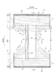
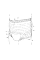
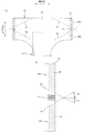
外装体の外側シートにおけるサイドシール部に係合部を形成した第1参考形態の使い捨ておむつについて説明する。図1,2に示すように、使い捨ておむつは、前身頃Fと後身頃Bを有する外装体20と、外装体20の装着者の身体面側に位置する内面に固定された内装体10から形成されている。
<Disposable diaper of the first reference form>
The disposable diaper of the first reference form in which the engaging portion is formed on the side seal portion of the outer sheet of the exterior body will be described. As shown in FIGS. 1 and 2, the disposable diaper is formed of an
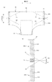
(内装体)
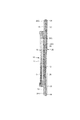
図3〜5に示すように、内装体10は、液透過性の表面シート11と、液不透過性の裏面シート12と、表面シート11と裏面シート12の間に設けられた吸収体13と、吸収体13の幅方向の両側部に設けられた立体ギャザーBSから形成されている。また、平面視における内装体10の形状は、一般的に略長方形形状に形成されている。なお、図3〜5のドッドは、ホットメルト接着剤等により固定させた部位を示している。
(Interior body)
As shown in FIGS. 3 to 5, the
表面シート11としては、有孔または無孔の不織布や多孔性プラスチックシート等が好ましい。不織布を構成する素材繊維は、ポリエチレンまたはポリプロピレン等のオレフィン系、ポリエステル系、ポリアミド系等の合成繊維の他、レーヨンやキュプラ等の再生繊維、綿等の天然繊維とすることができ、スパンレース法、スパンボンド法、サーマルボンド法、メルトブローン法、ニードルパンチ法等の適宜の加工法によって得られた不織布を用いることができる。これらの加工法の内、スパンレース法は柔軟性、ドレープ性に富む点で優れ、サーマルボンド法は嵩高でソフトである点で優れている。表面シート11に多数の透孔を形成した場合には、尿等が速やかに吸収されるようになり、ドライタッチ性に優れたものとなる。表面シート11の側部は、裏面シート12と吸収体13の側部を巻込んで吸収体13の外面まで延在している。
As the
裏面シート12としては、ポリエチレンまたはポリプロピレン等の液不透過性プラスチックシートが用いられるが、近年はムレ防止の点から透湿性を有するものが好ましい。遮水・透湿性シートは、たとえばポリエチレンやポリプロピレン等のオレフィン樹脂中に無機充填材を溶融混練してシートを形成した後、一軸または二軸方向に延伸することにより得られる微多孔性シートである。裏面シート12の側部は、折り返されて吸収体13の外面まで延在している。
As the
吸収体13としては、公知のもの、例えばパルプ繊維の積繊体、セルロースアセテート等のフィラメントの集合体、あるいは不織布を基本とし、必要に応じて高吸収性ポリマーを混合、固着等してなるものを用いることができる。また、吸収体13は、高吸収性ポリマー等の脱落を防止するために、液透過性のクレープ紙等の包装シート14によって包装されている。
The
平面視における吸収体13の形状は、股間部に括れ部分13Nを有する略砂時計形状に形成されているが、長方形状等に形成することもできる。括れ部分13Nの寸法は、適宜定めることができるが、装着者に使い捨ておむつをフィットさせるために、括れ部分13Nの縦方向の長さを使い捨ておむつの縦方向の長さの20〜50%にして、括れ部分13Nの幅方向の最狭幅を吸収体13の幅方向の幅の40〜60%にするのが好ましい。
The shape of the
立体ギャザーBSは、内装体10の幅方向の両側部に形成されている。立体ギャザーBSは、内装体10の外面の側部に固定された固定部と、固定部から内装体10の側部を経て内装体10の内面の側部まで延在する本体部から形成されている。また、本体部の縦方向の前後端部は、内装体10の内面上に固定され、本体部の縦方向の中間部は、内装体10の内面上に固定されず内面に向かって起立する。立体ギャザーBSは、2重の立体ギャザーシート15と縦方向に延在する細長状の立体ギャザー弾性部材16から形成されている。
The three-dimensional gather BS is formed on both sides of the
立体ギャザーシート15としては、ポリエチレンまたはポリプロピレン等のオレフィン系、ポリエステル系、アミド系等の合成繊維の他、レーヨンやキュプラ等の再生繊維、綿等の天然繊維とすることができ、スパンボンド法、サーマルボンド法、メルトブローン法、ニードルパンチ法等の適宜の加工方法に得られた不織布を用いることができるが、特にはムレを防止するために坪量を抑えて通気性に優れた不織布を用いるのがよい。さらに立体ギャザーシート15については、尿等の透過を防止するとともに、カブレを防止しかつ肌への感触性(ドライ感)を高めるために、シリコン系、パラフィン金属系、アルキルクロミッククロイド系撥水剤等をコーティングした撥水処理不織布を用いるのが好ましい。
The three-dimensional gather
立体ギャザー弾性部材16としては、通常使用されるスチレン系ゴム、オレフィン系ゴム、ウレタン系ゴム、エステル系ゴム、ポリウレタン、ポリエチレン、ポリスチレン、スチレンブタジエン、シリコン、ポリエステル等の素材を用いることができる。また、外側から見え難くするために、太さは925dtex以下、伸長率は150〜350%、間隔は10.0mm以下とするのが好ましい。なお、図4に二点鎖線で示すように、立体ギャザー弾性部材16は、その伸縮力によって立体ギャザーBSを内面に向かって起立させ、糸状の他、所定の幅を有するテープ状のものを用いることもできる。また、本明細書においては、伸長率は、伸張時の長さ/自然長の長さ×100[%]で算出し、自然長の長さを100%としている。
As the three-dimensional gather
(外装体)
図1,2に示すように、外装体20は、装着者の腹側に対向する前身頃Fに位置する前身頃シート22と背側に対向する後身頃Bに位置する後身頃シート23で形成され、前身頃シート22と後身頃シート23の幅方向の両側部はヒートシールによって溶着固定されサイドシール部21を形成する。また、前身頃シート22と後身頃シート23は、一体的に形成されている。これにより、図6に示すように、装着者の胴を通すためのウエスト開口と脚を通すための左右一対の脚開口が形成されている。なお、前身頃シート22と後身頃シート23は、脚開口部Lにおいて縦方向に分離して形成することもできる。
(Exterior body)
As shown in FIGS. 1 and 2, the
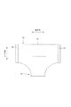
外装体20は、サイドシール部21を有する縦方向の前後領域である胴周り部Tと、前後の胴周り部Tを連結する脚開口部Lから形成されている。また、胴周り部Tは、概念的にウエスト開口に位置するウエスト部Wと、ウエスト部Wよりも脚開口部L側に位置するエスト下方部Uから形成されている。
The
図7に示すように、外側体20の前身頃シート22におけるサイドシール部21の外面、すなわち、外側体20の前身頃シート22におけるヒートシールによって溶着固定されサイドシール部21の外面には、複数の上側係合ピン46からなる幅方向に所定の間隔を有して上下方向に延在する上側係合部30Aと、複数の下側係合ピン47からなる幅方向に所定の間隔を有して上下方向に延在する下側係合部30Bが形成されている。
As shown in FIG. 7, a plurality of
上側係合部30Aの下側部と下側係合部30Bの上側部は、上下方向に所定の間隔を隔てて離間して形成され、サイドシール部21における上側係合部30Aの下側部と下側係合部30Bの上側部の間には、係合ピン45は形成されておらずヒートシール部31のみが形成されている。なお、上側係合ピン46と下側係合ピン47を総称して係合ピン45と言う。
The lower portion of the upper engaging
これにより、図8に示すように、使い捨ておむつの装着時には、サイドシール部21を前身頃シート22の幅方向の中心部に向かって折曲げて、前身頃シート22にサイドシール部21を係合部30で係合することによって使い捨ておむつの外観性を高めることができる。すなわち、使い捨ておむつの幅方向の両側に延在するサイドシール部21を前身頃シート22に固定して、使い捨ておむつの幅方向の両側に延在するサイドシール部21をなくすことによって使い捨ておむつの外観性を高めることができる。また、使い捨ておむつのサイズが大きい場合には、サイドシール部21を前身頃シート22の中心部に向かって折曲げることによって使い捨ておむつのウエスト開口と脚開口のサイズを小さくしてフィット性を高めることができる。なお、上側係合部30Aと下側係合部30Bを総称して係合部30と言う。
As a result, as shown in FIG. 8, when the disposable diaper is attached, the
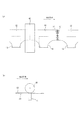
上側係合部30Aの下側部は、幅方向の外側に向けて下り傾斜に形成され、上側係合部30Aの下側端部を繋いだ上側折曲げ線A1と幅方向の延在する仮想線Aの交差角度θ1は30〜50度に形成されている。なお、交差角度θ1が30度未満の場合は、サイドシール部21の上側部を前身頃シート22の幅方向の中心部に向かって折曲げる、いわゆるクロス止めの効果が低下する。一方、交差角度θ1が60度超の場合は、サイズ調整範囲を所定以上に確保することができなくなる。
The lower portion of the upper engaging
下側係合部30Bの上側部は、幅方向の外側に向けて上り傾斜に形成され、下側係合部30Bの上側端部を繋いだ上側折曲げ線A2と幅方向の延在する仮想線Aの交差角度θ2は30〜50度に形成されている。なお、交差角度θ2は30度未満の場合は、サイドシール部21の上側部を前身頃シート22の幅方向の中心部に向かって折曲げる、いわゆるクロス止めの効果が低下する。一方、交差角度θ1が60度超の場合は、サイズ調整範囲を所定以上に確保することができなくなる。
The upper portion of the lower
これにより、図9に示すように、使い捨ておむつのサイズが大きい場合には、サイドシール部21の上側部を上側折曲げ線A1を中心として前身頃シート22の上下方向の下側部に向かって折曲げることによって使い捨ておむつのウエスト開口と脚開口のサイズを効率良く調整することができ、その調整範囲を大きくすることができる。なお、サイドシール部21の下側部を下側折曲げ線A2を中心として前身頃シート22の上下方向の上側部に向かって折曲げることもできる。また、使用された使い捨ておむつを廃棄する場合には、使い捨ておむつの股間部を前身頃シート22の上下方向の中心部に向かって折曲げて、その外側からサイドシール部21の上側部を上側折曲げ線A1を中心として前身頃シート22の幅方向の上下方向の下側部に向かって折曲げることによって、使用された使い捨ておむつをコンパクトに折曲げることができる。
As a result, as shown in FIG. 9, when the size of the disposable diaper is large, the upper portion of the
図7に示すように、上側係合部30Aを形成する上側係合ピン46は、幅方向と上下方向に所定の間隔を隔てて形成され、上側係合ピン46の先端部の長手方向が幅方向に平行に形成されている。また、下側係合部30Bを形成する下側係合ピン47は、幅方向と上下方向に所定の間隔を隔てて形成され、下側係合ピン47の先端部の長手方向が幅方向に平行に形成されている。これにより、サイドシール部21を前身頃シート22の幅方向の中心部に向けて折曲げた場合は、サイドシール部21を係合部30を介して前身頃シート22に確実に係合させることができる。
As shown in FIG. 7, the upper engaging
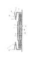
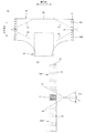
図3〜5に示すように、前身頃シート22と後身頃シート23は、それぞれ内側シート20Aと外側シート20Bから形成され、内側シート20Aと外側シート20Bの間、外側シート20Bにおけるウエスト開口部で内面側に折り返した折り返し部20Cの間には、弾性部材24〜28が設けられている。また、平面視において外装体20の幅方向の両側部には、脚開口を形成する凹状の脚周りライン29に沿って切断されて略砂時計形状に形成されている。なお、内側シート20Aと外側シート20Bとしては、表面シート11と同様に不織布で形成するのが好ましい。
As shown in FIGS. 3 to 5, the
前身頃シート22と後身頃シート23のウエスト部Wには、縦方向に所定の間隔を隔てて幅方向に延在する複数の細長状のウエスト部弾性部材24が設けられ、ウエスト下方部Uには、縦方向に所定の間隔を隔てて幅方向に延在する複数の細長状のウエスト下方部弾性部材25が設けられている。また、前身頃シート22と後身頃シート23の脚開口部Lには、幅方向に所定の間隔を隔てて脚周りライン29に沿って延在する複数の細長状の脚開口部弾性部材27が設けられ、前身頃シート22には、幅方向に所定の間隔を隔ててサイドシール部21から脚周りライン29に沿って延在する複数の細長状の湾曲弾性部材28が設けられ、後身頃シート23には、幅方向に所定の間隔を隔ててサイドシール部21から脚周りライン29に沿って延在する複数の細長状の湾曲弾性部材26が設けられている。
A plurality of elongated waist
成人用の使い捨ておむつの場合、ウエスト部弾性部材24の伸長率は160〜320%、ウエスト下方部弾性部材25と脚開口部弾性部材27の伸長率は160〜320%、湾曲弾性部材26,28の伸長率は230〜320%にすることが好ましい。これにより、外装体20を装着者に密着させることができる。
In the case of disposable diapers for adults, the
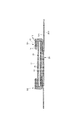
図1等に示すように、前身頃シート22の内面上には、内装体10の縦方向の前部を覆って、排泄物の前部からの漏れ出しを防止する不織布から形成された前押えシート18が設けられ、後身頃シート23の内面上には、内装体10の縦方向の後部を覆って、排泄物の後部からの漏れ出しを防止する不織布から形成された後押えシート19が設けられている。なお、前押えシート18は、前身頃シート22の折り返し部20Cの後部から内装体10の前端部と重なる位置まで延在し、後押えシート19は、後身頃シート23の折り返し部20Cの前部から内装体10の後端部と重なる位置まで延在している。
As shown in FIG. 1 and the like, on the inner surface of the
次に、他の形態について説明する。なお、第1参考形態の使い捨ておむつと同一部材については同一符号を付して説明を省略する。 Next, other forms will be described. The same members as the disposable diapers of the first reference embodiment are designated by the same reference numerals, and the description thereof will be omitted.
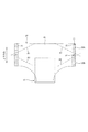
<第2参考形態の使い捨ておむつ>
図10に示すように、第2参考形態の使い捨ておむつの係合部30は、第1参考形態と同一形態である。第2参考形態の使い捨ておむつは、前身頃シート22におけるサイドシール部21の内側の近傍、すなわちサイドシール部21の側端部から0〜10mmの部位に、上端部から下側に向かって延在する上側スリット32Aと、下端部から上側に向かって延在する下側スリット32Bが設けられている。これにより、使い捨ておむつのサイズが大きい場合には、上側スリット32Aと下側スリット32Bを切断してサイドシール部21を前身頃シート22の中心部に向かって折曲げることによって使い捨ておむつのウエスト開口と脚開口のサイズを効率良く調整することができ、その調整範囲を大きくすることができる。なお、上側スリット32Aと下側スリット32Bのどちらか一方のみを設けることもできる。
<Disposable diaper of the second reference form>
As shown in FIG. 10, the disposable
<第3参考形態の使い捨ておむつ>
図11に示すように、第3参考形態の使い捨ておむつの係合部30は、第1参考形態と同一形態である。第3参考形態の使い捨ておむつは、前身頃シート22におけるサイドシール部21の内側の近傍、すなわちサイドシール部21の側端部から0〜10mmの部位に、上端部から下端部に向かって延在するミシン目33が設けられている。これにより、使い捨ておむつのサイズが大きい場合には、ミシン目33を切断してテープタイプの使い捨ておむつとして使用することができる。
<Third reference form of disposable diapers>
As shown in FIG. 11, the disposable
<第4参考形態の使い捨ておむつ>
図12に示すように、第4参考形態の使い捨ておむつの係合部30は、係合ピン45の形成を除いては第1参考形態と同一形態である。第4参考形態の上側係合部30Aを形成する上側係合ピン46は、幅方向と上下方向に所定の間隔を隔てて形成され、上側係合ピン46の先端部の長手方向が幅方向の外側に向かって上り傾斜に形成されている。また、下側係合部30Bを形成する下側係合ピン47は、幅方向と上下方向に所定の間隔を隔てて形成され、下側係合ピン47の先端部の長手方向が幅方向の外側に向かって下り傾斜に形成されている。これにより、使い捨ておむつのサイズが大きい場合には、サイドシール部21の上側部を上側折曲げ線A1を中心として前身頃シート22の上下方向の下側部に向かって折曲げた場合は、サイドシール部21を上側係合部30Aを介して前身頃シート22に確実に係合させることができ、サイドシール部21の下側部を下側折曲げ線A2を中心として前身頃シート22の上下方向の上側部に向かって折曲げた場合は、サイドシール部21を下側係合部30Bを介して前身頃シート22に確実に係合させることができる。
<Disposable diaper of the 4th reference form>
As shown in FIG. 12, the disposable
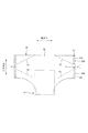
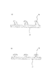
<実施形態の使い捨ておむつ>
図13に示すように、実施形態の使い捨ておむつの係合部30は、係合ピン45の形成を除いては第1参考形態と同一形態である。実施形態の上側係合部30Aを形成する第1上側係合ピン46Aは、幅方向と上下方向に所定の間隔を隔てて形成され、第1上側係合ピン46Aの先端部の長手方向が幅方向に平行に形成されている。また、第1上側係合ピン46Aの上下方向の間には、幅方向に所定の間隔を隔てて、第2上側係合ピン46Bの先端部の長手方向が幅方向の外側に向かって上り傾斜に形成された第2上側係合ピン46Bが形成されている。実施形態の下側係合部30Aを形成する第1下側係合ピン47Aは、幅方向と上下方向に所定の間隔を隔てて形成され、第1下側係合ピン47Aの先端部の長手方向が幅方向に平行に形成されている。また、第1下側係合ピン47Aの上下方向の間には、幅方向に所定の間隔を隔てて、第2下側係合ピン47Bの先端部の長手方向が幅方向の外側に向かって下り傾斜に形成された第2下側係合ピン47Bが形成されている。
<Disposable diaper of the embodiment>
As shown in FIG. 13, the disposable
これにより、使い捨ておむつの装着時には、サイドシール部21を前身頃シート22の幅方向の中心部に向かって折曲げて、前身頃シート22に係合部30を介してサイドシール部21を確実に係合することができる。また、使い捨ておむつのサイズが大きい場合には、サイドシール部21の上側部を上側折曲げ線A1を中心として前身頃シート22の幅方向の中心部に向かって折曲げた場合は、サイドシール部21を上側係合部30Aを介して前身頃シート22に確実に係合させることができ、サイドシール部21の下側部を下側折曲げ線A2を中心として前身頃シート22の幅方向の中心部に向かって折曲げた場合は、サイドシール部21を下側係合部30Bを介して前身頃シート22に確実に係合させることができる。
As a result, when the disposable diaper is attached, the
<第5参考形態の使い捨ておむつ>
図14に示すように、第5参考形態の使い捨ておむつの外側体20の前身頃シート22におけるサイドシール部21の外面には、複数の係合ピン45からなる幅方向に所定の間隔を有して上下方向に延在する係合部30が形成されている。また、幅方向の外側に向けて下り傾斜に形成される第1分断部34Aと、幅方向の外側に向けて上り傾斜に形成される第2分断部34Bによって区画されている。なお、第1分断部34Aと幅方向の延在する仮想線Aの交差角度θ1は30〜60度に形成し、第2分断部34Bと幅方向の延在する仮想線Aの交差角度θ2は30〜60度に形成されている。なお、第1分断部34Aと第2分断部34B総称して分断部34と言う。
<Disposable diaper of the 5th reference form>
As shown in FIG. 14, the outer surface of the
これにより、使い捨ておむつの装着時には、サイドシール部21を前身頃シート22の幅方向の中心部に向かって折曲げて、前身頃シート22に係合部30を介してサイドシール部21を確実に係合することができる。また、使い捨ておむつのサイズが大きい場合は、サイドシール部21の上側部をいずれかの第1分断部34Aを中心として前身頃シート22の幅方向の中心部に向かって折曲げた場合は、サイドシール部21を係合部30を介して前身頃シート22に確実に係合させることができ、サイドシール部21の下側部をいずれかの第2分断部34Bを中心として前身頃シート22の幅方向の中心部に向かって折曲げた場合は、サイドシール部21を係合部30を介して前身頃シート22に確実に係合させることができる。
As a result, when the disposable diaper is attached, the
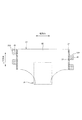
<第6参考形態の使い捨ておむつ>
図15に示すように、第6参考形態の使い捨ておむつの係合部30は、分断部34の形成を除いては第1参考形態と同一形態である。第6参考形態の上側係合部30Aは、上下方向に所定の間隔を隔てて幅方向の外側に向けて下り傾斜に形成された第1分断部34Aによって上下方向に分断されて形成されている。また、第6参考形態の下側係合部30Bは、上下方向に所定の間隔を隔てて幅方向の外側に向けて上り傾斜に形成された第2分断部34Bによって上下方向に分断されて形成されている。これにより、使い捨ておむつのサイズが大きい場合は、サイドシール部21の上側部をいずれかの第1分断部34Aを中心として前身頃シート22の幅方向の中心部に向かって折曲げることができ、使い捨ておむつのウエスト開口のサイズを効率良く調整することができる。また、サイドシール部21の下側部をいずれかの第2分断部34Bを中心として前身頃シート22の幅方向の中心部に向かって折曲げることができ、使い捨ておむつの脚開口のサイズを効率良く調整することができる。
<6th reference form of disposable diapers>
As shown in FIG. 15, the disposable
<第7参考形態の使い捨ておむつ>
図16に示すように、第7参考形態の使い捨ておむつの係合部30は、分断部34の形成を除いては第1参考形態と同一形態である。第7参考形態の上側係合部30Aは、上側係合部30Aの幅方向の中心部に上下方向に延在する第1分断部34Aによって幅方向に分断されて形成されている。また、第7参考形態の下側係合部30Bは、下側係合部30Bの幅方向の中心部に上下方向に延在する第2分断部34Bによって幅方向に分断されて形成されている。これにより、使い捨ておむつの装着時には、サイドシール部21を前身頃シート22の幅方向の中心部に向かって容易に折曲げることができる。
<7th reference form disposable diaper>
As shown in FIG. 16, the disposable
<第8参考形態の使い捨ておむつ>
図17に示すように、第8参考形態の使い捨ておむつは、サイドシール部21の幅方向の外側にそれぞれファスニング部35が設けられ、ファスニング部35の前身頃側の外面には、複数の係合ピン45からなる矩形状の係合部30が形成されている。
<8th reference form of disposable diapers>
As shown in FIG. 17, the disposable diaper of the eighth reference embodiment is provided with fastening portions 35 on the outer side in the width direction of the
使い捨ておむつの幅方向の右側には、上下方向に所定の間隔を隔てて2個のファスニング部35Aが設けられ、使い捨ておむつの幅方向の左側には、上下方向に所定の間隔を隔てて2個のファスニング部35Bが設けられている。上下方向において上側のファスニング部35Aの下側部と下側のファスニング部35Aの上側部の間に、上側のファスニング部35Bが位置し、下側のファスニング部35Aの下側部の下側に下側のファスニング部35Bが位置して設けられている。
Two
これにより、使い捨ておむつの装着時には、サイドシール部21の内側を中心としてファスニング部35を前身頃シート22の幅方向の中心部に向かって折曲げて、前身頃シート22に係合部30を介してファスニング部35を係合することによって使い捨ておむつの外観性を高めることができる。
As a result, when the disposable diaper is attached, the fastening portion 35 is bent toward the center in the width direction of the
次に、前身頃シート22のサイドシール部21の外面に係合部30を形成する方法について説明する。
Next, a method of forming the engaging
図18に示すように、超音波加工装置40は、サイドシール部21の下側に配置されサイドシール部21に超音波振動を伝動する超音波振動装置41と、超音波振動装置41の上側に配置された外周面に係合ピン45の溝が刻印されたアンビルローラ42から構成されている。サイドシール部21の外面をアンビルローラ42の外周面に当接させながら一定の速度でMD方向に移送する。これにより、サイドシール部21に位置する前身頃シート22と後身頃シート23を固定すると共に前身頃シート22の外面に、図19(a)に図示する鋸形状や、図19(b)に図示するT形状の係合ピン45を形成することができる。
As shown in FIG. 18, the ultrasonic processing device 40 is arranged on the lower side of the
本発明は、使い捨ておむつに利用できるものである。 The present invention can be used for disposable diapers.
10 内装体
11 表面シート
12 裏面シート
13 吸収体
20 外装体
21 サイドシール部
22 前身頃シート
23 後身頃シート
32A 上側スリット
32B 下側スリット
33 ミシン目
45 係合ピン
46 上側係合ピン
46A 第1上側係合ピン
46B 第2上側係合ピン
47 下側係合ピン
47A 第1下側係合ピン
47B 第2下側係合ピン
A 仮想線
A1 上側折曲げ線
A2 下側折曲げ線
10
Claims (4)
前記内装体を、液透過性の表面シートと、液不透過性の裏面シートと、前記表面シートと裏面シートの間の吸収体で形成し、
前記外装体を装着者の前身頃に位置する前身頃シートと、装着者の後身頃に位置する後身頃シートで形成し、
前記前身頃シートと後身頃シートを不織布で形成し、前記前身頃シートと後身頃シートを幅方向の両側部に形成されたサイドシール部で固定し、
前記前身頃シートのサイドシール部の外側面に、上下方向に所定の間隔を隔てて離間した複数の上側係合ピンからなる幅方向に所定の間隔を有して上下方向に延在する上側係合部と複数の下側係合ピンからなる幅方向に所定の間隔を有して上下方向に延在する下側係合部を形成し、
前記上側係合部の下側端部を繋いだ上側折曲げ線を幅方向外側に向けて下り傾斜に形成し、前記下側係合部の上側端部を繋いだ下側折曲げ線を幅方向外側に向けて上り傾斜に形成し、
前記上側係合ピンを第1上側係合ピンと第2上側係合ピンで形成し、前記第1上側係合ピンの先端部の長手方向を幅方向に沿って形成し、前記第2上側係合ピンの先端部の長手方向を幅方向外側に向けて上り傾斜に形成し、前記第1上側係合ピンと上下方向に隣接する第1上側係合ピンの間に前記第2上側係合ピンを形成し、
前記下側係合ピンを第1下側係合ピンと第2下側係合ピンで形成し、前記第1下側係合ピンの先端部の長手方向を幅方向に沿って形成し、前記第2下側係合ピンの先端部の長手方向を幅方向外側に向けて下り傾斜に形成し、前記第1下側係合ピンと上下方向に隣接する第1下側係合ピンの間に前記第2下側係合ピンを形成したことを特徴とする使い捨ておむつ。 In the interior body and a disposable diaper having an exterior body on the back surface of the interior body,
The interior body is formed of a liquid-permeable front sheet, a liquid-impermeable back sheet, and an absorber between the front sheet and the back sheet.
The exterior body is formed of a front body sheet located on the front body of the wearer and a back body sheet located on the back body of the wearer.
The front body sheet and the back body sheet are formed of a non-woven fabric, and the front body sheet and the back body sheet are fixed by side seal portions formed on both sides in the width direction.
On the outer surface of the side seal portion of the front body sheet, an upper hook extending in the vertical direction with a predetermined interval in the width direction composed of a plurality of upper engaging pins separated by a predetermined interval in the vertical direction. A lower engaging portion consisting of a joint portion and a plurality of lower engaging pins extending in the vertical direction with a predetermined interval in the width direction is formed.
The upper bending line connecting the lower ends of the upper engaging portion is formed in a downward slope toward the outside in the width direction, and the lower bending line connecting the upper ends of the lower engaging portion is widened. Formed in an upward slope toward the outside in the direction,
The upper engaging pin is formed by the first upper engaging pin and the second upper engaging pin, the longitudinal direction of the tip of the first upper engaging pin is formed along the width direction, and the second upper engaging pin is formed. The longitudinal direction of the tip of the pin is formed so as to be inclined outward in the width direction, and the second upper engaging pin is formed between the first upper engaging pin and the first upper engaging pin adjacent in the vertical direction. And
The lower engaging pin is formed by the first lower engaging pin and the second lower engaging pin, and the longitudinal direction of the tip portion of the first lower engaging pin is formed along the width direction. 2. The longitudinal direction of the tip of the lower engaging pin is formed so as to be downwardly inclined toward the outside in the width direction, and the first lower engaging pin is formed between the first lower engaging pin and the first lower engaging pin adjacent in the vertical direction. 2 Disposable diaper characterized by forming a lower engaging pin.
Priority Applications (1)
| Application Number | Priority Date | Filing Date | Title |
|---|---|---|---|
| JP2016192294A JP6861492B2 (en) | 2016-09-29 | 2016-09-29 | Disposable diapers |
Applications Claiming Priority (1)
| Application Number | Priority Date | Filing Date | Title |
|---|---|---|---|
| JP2016192294A JP6861492B2 (en) | 2016-09-29 | 2016-09-29 | Disposable diapers |
Publications (2)
| Publication Number | Publication Date |
|---|---|
| JP2018051081A JP2018051081A (en) | 2018-04-05 |
| JP6861492B2 true JP6861492B2 (en) | 2021-04-21 |
Family
ID=61832895
Family Applications (1)
| Application Number | Title | Priority Date | Filing Date |
|---|---|---|---|
| JP2016192294A Active JP6861492B2 (en) | 2016-09-29 | 2016-09-29 | Disposable diapers |
Country Status (1)
| Country | Link |
|---|---|
| JP (1) | JP6861492B2 (en) |
Family Cites Families (3)
| Publication number | Priority date | Publication date | Assignee | Title |
|---|---|---|---|---|
| JP3096152B2 (en) * | 1992-05-22 | 2000-10-10 | ユニ・チャーム株式会社 | Disposable diapers |
| US20030167049A1 (en) * | 2002-03-04 | 2003-09-04 | Gibbs Bernadette M. | Disposable absorbent garment with adjustable side panels |
| JP4839315B2 (en) * | 2005-09-29 | 2011-12-21 | 大王製紙株式会社 | Disposable diapers |
-
2016
- 2016-09-29 JP JP2016192294A patent/JP6861492B2/en active Active
Also Published As
| Publication number | Publication date |
|---|---|
| JP2018051081A (en) | 2018-04-05 |
Similar Documents
| Publication | Publication Date | Title |
|---|---|---|
| CN107874918B (en) | Disposable wearing article and method for manufacturing same | |
| JP4887217B2 (en) | Absorbent articles | |
| JP6108152B2 (en) | Disposable diapers | |
| JP6099136B2 (en) | Absorbent articles | |
| EP3202384B1 (en) | Disposable underwear-type diaper | |
| CN105455965B (en) | Disposable diaper having a disposable diaper | |
| JP2016067511A5 (en) | ||
| TWM574902U (en) | Absorbent article | |
| JP6307544B2 (en) | Pants type disposable products | |
| JP6058886B2 (en) | Absorbent articles | |
| JP2017169730A5 (en) | ||
| JP6942499B2 (en) | Pants type disposable diapers | |
| JP6903116B2 (en) | Pants type disposable diapers | |
| JP6861492B2 (en) | Disposable diapers | |
| JP5922366B2 (en) | Pants-type absorbent article | |
| JP6767294B2 (en) | Pants type disposable diapers | |
| JP5690050B2 (en) | Absorbent articles | |
| JP6261641B2 (en) | Disposable diapers | |
| JP6857990B2 (en) | Disposable diapers | |
| JP5999761B2 (en) | Pants-type disposable diaper | |
| JP2013074959A (en) | Pants type absorbent article | |
| JP6429961B2 (en) | Pants type disposable products | |
| JP6681866B2 (en) | Elastic member and pants-type disposable wearing article having the elastic member | |
| CN109982671B (en) | Absorbent article | |
| JP7557394B2 (en) | Disposable diapers |
Legal Events
| Date | Code | Title | Description |
|---|---|---|---|
| A621 | Written request for application examination |
Free format text: JAPANESE INTERMEDIATE CODE: A621 Effective date: 20190712 |
|
| A977 | Report on retrieval |
Free format text: JAPANESE INTERMEDIATE CODE: A971007 Effective date: 20200520 |
|
| A131 | Notification of reasons for refusal |
Free format text: JAPANESE INTERMEDIATE CODE: A131 Effective date: 20200529 |
|
| A521 | Request for written amendment filed |
Free format text: JAPANESE INTERMEDIATE CODE: A523 Effective date: 20200713 |
|
| A131 | Notification of reasons for refusal |
Free format text: JAPANESE INTERMEDIATE CODE: A131 Effective date: 20201211 |
|
| A521 | Request for written amendment filed |
Free format text: JAPANESE INTERMEDIATE CODE: A523 Effective date: 20210119 |
|
| TRDD | Decision of grant or rejection written | ||
| A01 | Written decision to grant a patent or to grant a registration (utility model) |
Free format text: JAPANESE INTERMEDIATE CODE: A01 Effective date: 20210319 |
|
| A61 | First payment of annual fees (during grant procedure) |
Free format text: JAPANESE INTERMEDIATE CODE: A61 Effective date: 20210330 |
|
| R150 | Certificate of patent or registration of utility model |
Ref document number: 6861492 Country of ref document: JP Free format text: JAPANESE INTERMEDIATE CODE: R150 |
|
| R250 | Receipt of annual fees |
Free format text: JAPANESE INTERMEDIATE CODE: R250 |
|
| R250 | Receipt of annual fees |
Free format text: JAPANESE INTERMEDIATE CODE: R250 |