JP6861475B2 - breakwater - Google Patents
breakwater Download PDFInfo
- Publication number
- JP6861475B2 JP6861475B2 JP2016098808A JP2016098808A JP6861475B2 JP 6861475 B2 JP6861475 B2 JP 6861475B2 JP 2016098808 A JP2016098808 A JP 2016098808A JP 2016098808 A JP2016098808 A JP 2016098808A JP 6861475 B2 JP6861475 B2 JP 6861475B2
- Authority
- JP
- Japan
- Prior art keywords
- bag
- foundation mound
- breakwater
- caisson
- land side
- Prior art date
- Legal status (The legal status is an assumption and is not a legal conclusion. Google has not performed a legal analysis and makes no representation as to the accuracy of the status listed.)
- Active
Links
- 239000012779 reinforcing material Substances 0.000 claims description 9
- 230000008595 infiltration Effects 0.000 claims description 5
- 238000001764 infiltration Methods 0.000 claims description 5
- 239000004575 stone Substances 0.000 description 19
- XLYOFNOQVPJJNP-UHFFFAOYSA-N water Substances O XLYOFNOQVPJJNP-UHFFFAOYSA-N 0.000 description 18
- 239000000463 material Substances 0.000 description 16
- 230000003014 reinforcing effect Effects 0.000 description 13
- 238000009991 scouring Methods 0.000 description 6
- 238000010276 construction Methods 0.000 description 4
- 238000010586 diagram Methods 0.000 description 3
- 230000000694 effects Effects 0.000 description 3
- 230000035699 permeability Effects 0.000 description 3
- 239000011148 porous material Substances 0.000 description 3
- 239000013535 sea water Substances 0.000 description 3
- 238000010030 laminating Methods 0.000 description 2
- 230000002787 reinforcement Effects 0.000 description 2
- 210000001015 abdomen Anatomy 0.000 description 1
- 230000015572 biosynthetic process Effects 0.000 description 1
- 230000007423 decrease Effects 0.000 description 1
Images
Classifications
-
- Y—GENERAL TAGGING OF NEW TECHNOLOGICAL DEVELOPMENTS; GENERAL TAGGING OF CROSS-SECTIONAL TECHNOLOGIES SPANNING OVER SEVERAL SECTIONS OF THE IPC; TECHNICAL SUBJECTS COVERED BY FORMER USPC CROSS-REFERENCE ART COLLECTIONS [XRACs] AND DIGESTS
- Y02—TECHNOLOGIES OR APPLICATIONS FOR MITIGATION OR ADAPTATION AGAINST CLIMATE CHANGE
- Y02A—TECHNOLOGIES FOR ADAPTATION TO CLIMATE CHANGE
- Y02A10/00—TECHNOLOGIES FOR ADAPTATION TO CLIMATE CHANGE at coastal zones; at river basins
- Y02A10/11—Hard structures, e.g. dams, dykes or breakwaters
Landscapes
- Revetment (AREA)
Description
本発明は、地震時の津波、台風時の高波や高潮による陸側への災害を抑制する防波堤に関するものである。 The present invention relates to a breakwater that suppresses a disaster on the land side due to a tsunami during an earthquake, a high wave during a typhoon, or a storm surge.
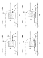
従来の防波堤50は、図6に示すように、海底に造成された基礎マウンド2(捨石層)上に重量構造物3(以下、ケーソンという)を配置して構成されている。この従来の防波堤50に津波等の大きな波が到達した場合、沖側の水位が上昇することで、沖側の水域と陸側の水域との間に水位差Hが生じ、基礎マウンド2内に沖側から陸側に向かう浸透流が発生する(図6の基礎マウンド2内の矢印)。そして、沖側の水域と陸側の水域との間の水位差Hが増加するに伴い、浸透流の動水勾配が大きくなる。これにより、基礎マウンド2の安定性が損なわれ、崩壊する虞がある。特に、ケーソン3の陸側の下端部付近の基礎マウンド2内は、局所的に浸透流の動水勾配が大きく、間隙水圧が局所的に大きくなることから、この箇所が最初に崩壊して、基礎マウンド2全体が崩壊することで、ケーソン3が傾倒するようになる(図6の2点鎖線参照)。
As shown in FIG. 6, the
これを対策するために、図7に示すように、ケーソン3の陸側の基礎マウンド2上に、礫材や石材を積み上げた補強体(腹付工)55を設けることによって、津波によるケーソン3の傾倒を抑制する防波堤51が提案されている(非特許文献1参照)。この防波堤51では、基礎マウンド2内の浸透流路長(図7(a)の基礎マウンド2内の矢印の長さ相当)を、図6に示す防波堤50の基礎マウンド2内の浸透流路長(図6の基礎マウンド2内の矢印の長さ相当)よりも長くすることができ、その結果、ケーソン3の陸側の下端部付近の基礎マウンド2内の動水勾配を小さくすることができ、しかも、補強体55によって基礎マウンド2への上載圧を増加させることもでき、津波等の際の基礎マウンド2の安定性が向上する。
In order to deal with this, as shown in FIG. 7, by providing a reinforcing body (belly work) 55 on which gravel and stones are piled up on the
しかしながら、上述した、図7に示す防波堤51では、基礎マウンド2上で、ケーソン3の陸側の面に沿うように、石材や礫材を積層してなる補強体55を設けるために、補強体55の体積が非常に大きくなり、大量の礫材や石材を使用しなければならず、経済的に不利である。しかもこの防波堤51では、港内(防波堤51から陸側の水域)の有効な範囲が減少してしまい、すなわち、補強体55により船舶の移動範囲が限定されるなど、港湾運用上、いくつかの制約が発生する可能性がある。そのために、石材や礫材を減少させて補強体55の体積を小さくしてしまうと、津波等がケーソン3を越流した場合、図7(b)〜(d)に示すように、その越流により補強体55が洗掘され、その結果、基礎マウンド2の安定性を確保できず、補強体55による作用効果がすぐに失われる可能性がある。
However, in the
すなわち、津波等がケーソン3を越流した場合、図7(b)〜(d)に示すように、ケーソン3の天端を勢いよく越流した海水により、基礎マウンド2の、ケーソン3の陸側の面から少し離れた位置が洗掘され、その洗掘範囲が大きくなるにつれて、ケーソン3の陸側の面に沿って積層された礫材や石材(補強体55)がこの洗掘範囲に崩れ落ちることで、ケーソン3の陸側の面に沿う位置の補強体55の体積が徐々に減少して、当該箇所が浸透流により不安定となり、基礎マウンド2の安定性を確保することができず、ケーソン3が傾倒するようになる。
That is, when a tsunami or the like overflows the
本発明は、かかる点に鑑みてなされたものであり、補強構造の規模が小さく、簡易な構造で、その施工も容易でありながら、津波等の有事の際、重量構造物が載置される捨石層の安定性を確保して、その防波機能を発揮することのできる防波堤を提供することを目的とする。 The present invention has been made in view of this point, and while the scale of the reinforcing structure is small, the structure is simple, and the construction is easy, a heavy structure is placed in the event of an emergency such as a tsunami. The purpose is to ensure the stability of the rubble layer and to provide a breakwater capable of exerting its wave-breaking function.
本発明は、上記課題を解決するための手段として、請求項1に記載した発明は、海底に造成した捨石層上に配設される重量構造物と、該重量構造物の陸側の面に当接するように前記捨石層上に配置され、網状の袋体に多数の補強材を充填してなる、透水性を有する袋状ユニットと、を備え、前記捨石層の内部から前記袋状ユニットの内部に亘って形成される浸透流路の長さを調整すべく、前記袋状ユニットを複数段積層することを特徴とするものである。
請求項2に記載した発明は、請求項1に記載した発明において、前記捨石層は、基礎マウンドであることを特徴とするものである。
請求項1及び2の発明では、網状の袋体に、礫材や石材等の多数の補強材を充填した袋状ユニットを、重量構造物の陸側の面に当接するように、捨石層としての基礎マウンド上に配置することで、浸透流によって基礎マウンドの不安定化が最も起こり易い箇所を局所的に小規模で、且つ効率的に、さらに経済的に補強することができる。
According to the first aspect of the present invention, as a means for solving the above problems, the invention described in
The invention according to
In the inventions of
また、請求項1及び2の発明では、津波等の有事の際、重量構造物の天端を勢いよく越流した海水により、基礎マウンドの、重量構造物の陸側の面から少し離れた位置が洗掘され、その洗掘範囲が大きくなっても、従来のように、礫材や石材がその洗掘範囲に崩れ落ちることはなく、袋体ユニットが重量構造物の陸側の基礎マウンド上に継続的に載置されるので、基礎マウンドの安定性を確保することができる。
さらに、請求項1及び2の発明では、網状の袋体に補強材として礫材や石材等を充填した、可撓性を有する袋状ユニットを採用しているので、基礎マウンドの上面の変状に対して馴染みが良く、その変状への追従性があり、その作用効果を継続的に維持することができる。
さらにまた、請求項1及び2の発明では、袋状ユニットは透過性を有し、該袋状ユニットを重量構造物の陸側の面に当接するように捨石層上に複数段積層するので、基礎マウンド内の浸透流路長を、従来(図6に示す防波堤)よりも長くすることができ、その結果、重量構造物の陸側の下端部付近の基礎マウンド内の動水勾配を小さくすることができ、間隙水圧の局所的な上昇を抑制することができる。これにより、浸透流による当該箇所の崩壊を抑制して、基礎マウンド全体の安定性を確保することができる。しかも、複数段に積層された袋状ユニットによって基礎マウンドへの上載圧を増加させることができ、津波等の有事の際の基礎マウンドの安定性をさらに確保するができる。
Further, in the inventions of
Further, in the inventions of
Furthermore, in the inventions of
請求項3に記載した発明は、請求項1または2に記載した発明において、前記袋状ユニットは、陸側に向かって複数列配置されることを特徴とするものである。
請求項3の発明では、陸側に複数列配置された袋状ユニットによって基礎マウンドへの上載圧をさらに増加させることができ、津波等の有事の際の基礎マウンドの安定性をさらに確保することができる。
The invention according to
In the invention of
本発明の防波堤によれば、網状の袋体に補強材として礫材や石材等を充填した袋状ユニットを、重量構造物の陸側の面に当接するように、捨石層、例えば、基礎マウンド上に配置する補強構造を採用したので、簡易な補強構造でその規模を小さくでき、その施工も容易であるうえ、津波等の有事の際、基礎マウンドの安定性を確保することができ、その防波機能を発揮することができる。 According to the breakwater of the present invention, a rubble layer, for example, a foundation mound, is provided so that a bag-shaped unit in which a net-like bag body is filled with gravel or stone as a reinforcing material is in contact with the land side surface of a heavy structure. Since the reinforcement structure placed above is adopted, the scale can be reduced with a simple reinforcement structure, the construction is easy, and the stability of the foundation mound can be ensured in the event of an emergency such as a tsunami. It can exert a wave-proof function.
以下、本発明を実施するための形態を図1〜図5に基づいて詳細に説明する。
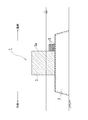
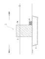
本発明の実施の形態に係る防波堤1は、地震時の津波、台風時の高波や高潮による陸側への災害を抑制するためのものである。図1及び図2に示すように、本防波堤1は、海底に造成した、捨石層としての基礎マウンド2上に配設される重量構造物としてのケーソン3と、該ケーソン3の陸側の面3aに当接するように基礎マウンド2上に配置され、網状の袋体6(図3参照)に多数の補強材7(図3参照)を充填してなる袋状ユニット5と、を備えている。この袋状ユニット5の補強材7は、礫材や石材に相当する。
Hereinafter, embodiments for carrying out the present invention will be described in detail with reference to FIGS. 1 to 5.
The
図1及び図2に示すように、基礎マウンド2は、海底地盤上に捨石や被覆石を積層して造成される。該基礎マウンド2は、断面台形状で防波機能を発揮すべく所定方向に延びている。該基礎マウンド2上には、ケーソン3が該基礎マウンド2の長手方向に沿って複数配置される。該ケーソン3は、コンクリート製の直方体状の箱体の内部に中詰材として砕石等が充填されて構成される。なお、ケーソン3は、直方体状の箱体に限らず、基礎マウンド2の延びる方向に対して直交する断面台形状の箱体を採用してもよく、その形状が限定されることはない。
As shown in FIGS. 1 and 2, the
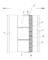
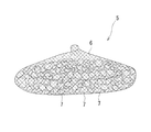
図3に示すように、袋状ユニット5は、網状の袋体6に多数の礫材や石材7を充填して構成され、可撓性を有するものである。該袋状ユニット5は、網状の袋体6に多数の礫材や石材7を充填して構成されているので、良好な透水性を有するものである。該袋状ユニット5は、図1及び図3に示すように、楕円体状あるいは略直方体状の姿勢で、ケーソン3の陸側の面3aに当接するように基礎マウンド2上に配置される。袋状ユニット5は、図2も参照して、1台のケーソン3に対して、基礎マウンド2の長手方向に沿って互いに当接するように複数配置され、しかも、上方に向かって複数段に積層される。なお、図示はしていないが、袋状ユニット5を、ケーソン3の陸側の基礎マウンド2上に、陸側に向かって複数列配置してもよい。本実施形態では、袋状ユニット5は、1台のケーソン3に対して、基礎マウンド2の長手方向に沿って互いに当接するように3台配置され、且つ3段積層されている。なお、袋状ユニット5は、積層する段数が増加すればするほど、浸透流路の長さ(図4の基礎マウンド2内の矢印の長さ相当)が長くなり、上載圧も大きくなるが、積層された袋状ユニット5全体の安定性や、そのコストに応じてその段数が設定される。
As shown in FIG. 3, the bag-shaped
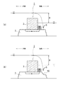
次に、本発明の実施形態に係る防波堤1の作用を図4に基づいて説明する。
津波等の有事の際、海水が本防波堤1のケーソン3の天端を勢いよく越流(図4の矢印参照)すると、基礎マウンド2の、ケーソン3の陸側の面3aから少し離れた位置が洗掘(図4(b)の凹んだ箇所10)され、その洗掘範囲10が大きくなる。しかしながら、本防波堤1では、複数の袋状ユニット5が、ケーソン3の陸側の面3aに当接するように基礎マウンド2上に積層されているので、従来のように、積層された礫材や石材がその洗掘範囲10に崩れ落ちることはなく、浸透流(沖側の水域と陸側の水域との間の水位差Hによる)によって基礎マウンド2の不安定化が最も起こり易いケーソン3の陸側の下端付近が継続的に補強される。その結果、基礎マウンド2の安定性を確保することができ、ケーソン3の傾倒を抑制することができる。また、複数の袋状ユニット5により、ケーソン3の陸側への滑動を抑制することもできる。
Next, the operation of the
In the event of a tsunami or other emergency, when seawater vigorously overflows the top of
また、複数の袋状ユニット5、5が積層され、各袋状ユニット5、5は透水性を有するので、基礎マウンド2内の浸透流路長(図4の基礎マウンド2内の矢印の長さ相当)を従来(図6に示す防波堤50)よりも長くすることができ、その結果、ケーソン3の陸側の下端部付近の基礎マウンド2内の動水勾配を小さくすることができ、間隙水圧の局所的な上昇を抑制することができる。これにより、浸透流による、基礎マウンド2の、ケーソン3の陸側の下端付近の崩壊をさらに抑制することができ、基礎マウンド2全体の安定性を確保することができる。しかも、複数段に積層された袋状ユニット5、5によって基礎マウンド2への上載圧を増加させることができ、基礎マウンド2の安定性をさらに確保することができる。
さらに、袋状ユニット5は可撓性を有しているので、基礎マウンド2の上面の変状に追従するように変形することができ、その作用効果を継続的に奏することができる。
Further, since a plurality of bag-shaped
Further, since the bag-shaped
このように、本発明の実施形態に係る防波堤1は、基礎マウンド2上で、ケーソン3の陸側の面3aに当接するように、網状の袋体6に多数の礫材や石材7である補強材を充填してなる袋状ユニット5を配置して構成されている。これにより、津波等の有事の際の、基礎マウンド2内の浸透流による、またケーソン3の天端からの越流による、基礎マウンド2内で、ケーソン3の陸側の下端部付近の不安定化を抑制でき、ひいては、基礎マウンド2全体の安定化を確保することができ、ケーソン3の傾倒を抑制することができ、防波機能を継続させることができる。
As described above, the
また、本発明の実施形態に係る防波堤1では、袋状ユニット5を採用することにより、補強構造の規模を小さくでき、簡易な構造で、その施工も容易とすることができる。すなわち、袋状ユニット5を配置している領域を図7に示す従来の補強体55の領域よりも小さくすることができ、その結果、従来よりも礫材や石材7を少量にでき、施工も容易となり、トータルコストを削減することができる。また、港内(防波堤1から陸側の水域)の有効な範囲、例えば船舶の移動範囲等を従来よりも増加させることができる。
Further, in the
なお、本実施形態に係る防波堤1では、袋状ユニット5が、ケーソン3の陸側の面3aに当接するように基礎マウンド2上に3段配置されているが、必要に応じて、1段、2段または4段以上配置してもよい。また、上述したが、袋状ユニット5を、ケーソン2の陸側の基礎マウンド2上に、陸側に向かって複数列配置してもよい。
In the
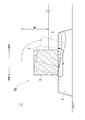
また、上述した防波堤1(図1〜図4)では、海底に造成した基礎マウンド2上に配設されるケーソン3の陸側の面3aに当接するようにして、その基礎マウンド2上に複数の袋状ユニット5を配設する形態を採用したが、図5に示すように、海底地盤内に設けた多数の捨石を積層してなる捨石層2上に配設されるケーソン3の陸側の面3aに当接するようにして、その捨石層2上に複数の袋状ユニット5を配設する形態を採用してもよい。
Further, in the breakwater 1 (FIGS. 1 to 4) described above, a plurality of breakwaters 1 (FIGS. 1 to 4) are placed on the
1 防波堤,2 基礎マウンド(捨石層),3 ケーソン(重量構造物),3a 陸側の面,5 袋状ユニット,6 袋体,7 礫材や石材(補強材) 1 Breakwater, 2 Foundation mound (rubble layer), 3 Caisson (heavy structure), 3a Land side surface, 5 bag-shaped unit, 6 bag body, 7 gravel and stone (reinforcing material)
Claims (3)
該重量構造物の陸側の面に当接するように前記捨石層上に配置され、網状の袋体に多数の補強材を充填してなる、透水性を有する袋状ユニットと、
を備え、
前記捨石層の内部から前記袋状ユニットの内部に亘って形成される浸透流路の長さを調整すべく、前記袋状ユニットを複数段積層することを特徴とする防波堤。 Heavy-duty structures placed on the rubble layer created on the seabed,
A water-permeable bag-shaped unit arranged on the rubble layer so as to abut on the land-side surface of the heavy-duty structure and filled with a large number of reinforcing materials in a net-like bag body.
With
A breakwater characterized in that the bag-shaped units are laminated in a plurality of stages in order to adjust the length of the infiltration flow path formed from the inside of the rubble layer to the inside of the bag-shaped unit.
Priority Applications (1)
| Application Number | Priority Date | Filing Date | Title |
|---|---|---|---|
| JP2016098808A JP6861475B2 (en) | 2016-05-17 | 2016-05-17 | breakwater |
Applications Claiming Priority (1)
| Application Number | Priority Date | Filing Date | Title |
|---|---|---|---|
| JP2016098808A JP6861475B2 (en) | 2016-05-17 | 2016-05-17 | breakwater |
Publications (2)
| Publication Number | Publication Date |
|---|---|
| JP2017206843A JP2017206843A (en) | 2017-11-24 |
| JP6861475B2 true JP6861475B2 (en) | 2021-04-21 |
Family
ID=60417120
Family Applications (1)
| Application Number | Title | Priority Date | Filing Date |
|---|---|---|---|
| JP2016098808A Active JP6861475B2 (en) | 2016-05-17 | 2016-05-17 | breakwater |
Country Status (1)
| Country | Link |
|---|---|
| JP (1) | JP6861475B2 (en) |
Family Cites Families (8)
| Publication number | Priority date | Publication date | Assignee | Title |
|---|---|---|---|---|
| JPS59122626A (en) * | 1982-12-28 | 1984-07-16 | Penta Ocean Constr Co Ltd | Construction of underwater foundation |
| ES8607453A1 (en) * | 1985-05-31 | 1986-06-01 | Suares Bores Pedro | Energy-dissipating overflow-type protection system on dikes and/or jetties |
| JPH086341B2 (en) * | 1987-07-08 | 1996-01-24 | 昭市 山下 | Rubble mound protection method |
| JP2001279640A (en) * | 2000-03-31 | 2001-10-10 | Wakachiku Construction Co Ltd | Submerged structure |
| JP4881972B2 (en) * | 2009-03-30 | 2012-02-22 | 大豊建設株式会社 | Submarine caisson and submarine caisson reinforcement and repair method |
| JP6128725B2 (en) * | 2011-07-08 | 2017-05-17 | 東洋建設株式会社 | breakwater |
| JP6128726B2 (en) * | 2011-07-08 | 2017-05-17 | 東洋建設株式会社 | breakwater |
| JP6004312B2 (en) * | 2012-02-01 | 2016-10-05 | 五洋建設株式会社 | Reinforcement structure of caisson breakwater |
-
2016
- 2016-05-17 JP JP2016098808A patent/JP6861475B2/en active Active
Also Published As
| Publication number | Publication date |
|---|---|
| JP2017206843A (en) | 2017-11-24 |
Similar Documents
| Publication | Publication Date | Title |
|---|---|---|
| JP6171569B2 (en) | Embankment reinforcement structure | |
| JP6077962B2 (en) | Sliding breakwater | |
| JP6760760B2 (en) | Embankment structure | |
| KR101666626B1 (en) | Shore bank using frame and geotextile, and method for constructing this same | |
| JP6861475B2 (en) | breakwater | |
| JPH09279540A (en) | Seismic strengthening structure for gravity port structure | |
| JP6689032B2 (en) | Breakwater structure | |
| JP2013023874A (en) | Breakwater water structure | |
| JP7440864B2 (en) | Embankment reinforcement method | |
| JP5322068B1 (en) | Construction method of submarine | |
| JP5541267B2 (en) | Tide barrier | |
| KR101124591B1 (en) | Breakwater and seawall having superstructure | |
| JP6881916B2 (en) | How to install the structure | |
| JP5949643B2 (en) | Reinforcement structure of caisson type hybrid bank and method for constructing the reinforcement structure | |
| JP7309147B2 (en) | Caisson, pneumatic caisson construction method and structure | |
| JP5983436B2 (en) | Gravity breakwater | |
| JP5872797B2 (en) | High stability type breakwater | |
| JP6128725B2 (en) | breakwater | |
| JP5234415B2 (en) | Sea area control structure | |
| JP6338837B2 (en) | Coastal dike | |
| JP6923282B2 (en) | Rubble stone structure and its construction method | |
| JP4521491B2 (en) | Foundation structure of offshore structure and its construction method | |
| US20260028789A1 (en) | Device and method for coastal erosion mitigation using concrete dome structures | |
| JP4927355B2 (en) | How to build a sloping bank | |
| KR101536082B1 (en) | Underwater stucture and installation method thereof |
Legal Events
| Date | Code | Title | Description |
|---|---|---|---|
| A621 | Written request for application examination |
Free format text: JAPANESE INTERMEDIATE CODE: A621 Effective date: 20190515 |
|
| A977 | Report on retrieval |
Free format text: JAPANESE INTERMEDIATE CODE: A971007 Effective date: 20200603 |
|
| A131 | Notification of reasons for refusal |
Free format text: JAPANESE INTERMEDIATE CODE: A131 Effective date: 20200722 |
|
| A521 | Request for written amendment filed |
Free format text: JAPANESE INTERMEDIATE CODE: A523 Effective date: 20200909 |
|
| TRDD | Decision of grant or rejection written | ||
| A01 | Written decision to grant a patent or to grant a registration (utility model) |
Free format text: JAPANESE INTERMEDIATE CODE: A01 Effective date: 20210303 |
|
| A61 | First payment of annual fees (during grant procedure) |
Free format text: JAPANESE INTERMEDIATE CODE: A61 Effective date: 20210330 |
|
| R150 | Certificate of patent or registration of utility model |
Ref document number: 6861475 Country of ref document: JP Free format text: JAPANESE INTERMEDIATE CODE: R150 |
|
| R250 | Receipt of annual fees |
Free format text: JAPANESE INTERMEDIATE CODE: R250 |