JP6859331B2 - Microfluidic fan - Google Patents
Microfluidic fan Download PDFInfo
- Publication number
- JP6859331B2 JP6859331B2 JP2018515757A JP2018515757A JP6859331B2 JP 6859331 B2 JP6859331 B2 JP 6859331B2 JP 2018515757 A JP2018515757 A JP 2018515757A JP 2018515757 A JP2018515757 A JP 2018515757A JP 6859331 B2 JP6859331 B2 JP 6859331B2
- Authority
- JP
- Japan
- Prior art keywords
- electrode
- flow
- gaseous fluid
- emitter
- flange
- Prior art date
- Legal status (The legal status is an assumption and is not a legal conclusion. Google has not performed a legal analysis and makes no representation as to the accuracy of the status listed.)
- Active
Links
- 239000012530 fluid Substances 0.000 claims description 67
- 238000000034 method Methods 0.000 claims description 28
- 239000000463 material Substances 0.000 claims description 16
- 238000004519 manufacturing process Methods 0.000 claims description 9
- 239000000758 substrate Substances 0.000 claims description 9
- 229910052751 metal Inorganic materials 0.000 claims description 7
- 239000002184 metal Substances 0.000 claims description 7
- 239000000725 suspension Substances 0.000 claims description 4
- 238000000151 deposition Methods 0.000 claims description 3
- 238000001816 cooling Methods 0.000 description 19
- 125000006850 spacer group Chemical group 0.000 description 13
- 230000005684 electric field Effects 0.000 description 11
- 230000006870 function Effects 0.000 description 5
- 230000035882 stress Effects 0.000 description 5
- 230000000694 effects Effects 0.000 description 4
- 150000002500 ions Chemical class 0.000 description 4
- 238000005452 bending Methods 0.000 description 3
- 230000003993 interaction Effects 0.000 description 3
- 239000002086 nanomaterial Substances 0.000 description 3
- 239000002245 particle Substances 0.000 description 3
- 238000005245 sintering Methods 0.000 description 3
- 238000003860 storage Methods 0.000 description 3
- 238000003466 welding Methods 0.000 description 3
- XKRFYHLGVUSROY-UHFFFAOYSA-N Argon Chemical compound [Ar] XKRFYHLGVUSROY-UHFFFAOYSA-N 0.000 description 2
- IJGRMHOSHXDMSA-UHFFFAOYSA-N Atomic nitrogen Chemical compound N#N IJGRMHOSHXDMSA-UHFFFAOYSA-N 0.000 description 2
- CURLTUGMZLYLDI-UHFFFAOYSA-N Carbon dioxide Chemical compound O=C=O CURLTUGMZLYLDI-UHFFFAOYSA-N 0.000 description 2
- RYGMFSIKBFXOCR-UHFFFAOYSA-N Copper Chemical compound [Cu] RYGMFSIKBFXOCR-UHFFFAOYSA-N 0.000 description 2
- CBENFWSGALASAD-UHFFFAOYSA-N Ozone Chemical compound [O-][O+]=O CBENFWSGALASAD-UHFFFAOYSA-N 0.000 description 2
- 230000015572 biosynthetic process Effects 0.000 description 2
- 238000004891 communication Methods 0.000 description 2
- 239000004020 conductor Substances 0.000 description 2
- 239000000356 contaminant Substances 0.000 description 2
- 229910052802 copper Inorganic materials 0.000 description 2
- 239000010949 copper Substances 0.000 description 2
- 238000005516 engineering process Methods 0.000 description 2
- 238000002474 experimental method Methods 0.000 description 2
- 239000007789 gas Substances 0.000 description 2
- 229910052737 gold Inorganic materials 0.000 description 2
- 238000002347 injection Methods 0.000 description 2
- 239000007924 injection Substances 0.000 description 2
- 238000007650 screen-printing Methods 0.000 description 2
- 238000005476 soldering Methods 0.000 description 2
- 229910001220 stainless steel Inorganic materials 0.000 description 2
- 239000010935 stainless steel Substances 0.000 description 2
- 238000011144 upstream manufacturing Methods 0.000 description 2
- 229910018072 Al 2 O 3 Inorganic materials 0.000 description 1
- 239000006091 Macor Substances 0.000 description 1
- 238000004026 adhesive bonding Methods 0.000 description 1
- 239000003570 air Substances 0.000 description 1
- 239000012080 ambient air Substances 0.000 description 1
- 229910052786 argon Inorganic materials 0.000 description 1
- QVGXLLKOCUKJST-UHFFFAOYSA-N atomic oxygen Chemical compound [O] QVGXLLKOCUKJST-UHFFFAOYSA-N 0.000 description 1
- 238000005219 brazing Methods 0.000 description 1
- 239000013590 bulk material Substances 0.000 description 1
- 239000001569 carbon dioxide Substances 0.000 description 1
- 229910002092 carbon dioxide Inorganic materials 0.000 description 1
- 239000000969 carrier Substances 0.000 description 1
- 239000003054 catalyst Substances 0.000 description 1
- 239000000919 ceramic Substances 0.000 description 1
- 229910010293 ceramic material Inorganic materials 0.000 description 1
- 239000011248 coating agent Substances 0.000 description 1
- 238000000576 coating method Methods 0.000 description 1
- 238000004590 computer program Methods 0.000 description 1
- 239000002826 coolant Substances 0.000 description 1
- 238000005520 cutting process Methods 0.000 description 1
- 230000001419 dependent effect Effects 0.000 description 1
- 238000009792 diffusion process Methods 0.000 description 1
- 238000005530 etching Methods 0.000 description 1
- 238000000227 grinding Methods 0.000 description 1
- 230000017525 heat dissipation Effects 0.000 description 1
- 239000001307 helium Substances 0.000 description 1
- 229910052734 helium Inorganic materials 0.000 description 1
- SWQJXJOGLNCZEY-UHFFFAOYSA-N helium atom Chemical compound [He] SWQJXJOGLNCZEY-UHFFFAOYSA-N 0.000 description 1
- 239000012535 impurity Substances 0.000 description 1
- 238000001746 injection moulding Methods 0.000 description 1
- 239000012212 insulator Substances 0.000 description 1
- 239000011159 matrix material Substances 0.000 description 1
- 150000002739 metals Chemical class 0.000 description 1
- 238000003801 milling Methods 0.000 description 1
- 239000000203 mixture Substances 0.000 description 1
- 238000010295 mobile communication Methods 0.000 description 1
- 238000000465 moulding Methods 0.000 description 1
- 229910052759 nickel Inorganic materials 0.000 description 1
- 229910052757 nitrogen Inorganic materials 0.000 description 1
- 230000003287 optical effect Effects 0.000 description 1
- 239000001301 oxygen Substances 0.000 description 1
- 229910052760 oxygen Inorganic materials 0.000 description 1
- 230000002093 peripheral effect Effects 0.000 description 1
- 238000007747 plating Methods 0.000 description 1
- 229910052697 platinum Inorganic materials 0.000 description 1
- 229920000642 polymer Polymers 0.000 description 1
- 230000008569 process Effects 0.000 description 1
- 230000001737 promoting effect Effects 0.000 description 1
- 230000001681 protective effect Effects 0.000 description 1
- 238000005086 pumping Methods 0.000 description 1
- 230000009467 reduction Effects 0.000 description 1
- 239000004065 semiconductor Substances 0.000 description 1
- 239000007787 solid Substances 0.000 description 1
- 238000000638 solvent extraction Methods 0.000 description 1
- 238000005507 spraying Methods 0.000 description 1
- 238000004544 sputter deposition Methods 0.000 description 1
- 230000008646 thermal stress Effects 0.000 description 1
- 230000007723 transport mechanism Effects 0.000 description 1
- 229910052721 tungsten Inorganic materials 0.000 description 1
- 238000007740 vapor deposition Methods 0.000 description 1
- 239000002699 waste material Substances 0.000 description 1
- 229910052726 zirconium Inorganic materials 0.000 description 1
Images


Classifications
-
- F—MECHANICAL ENGINEERING; LIGHTING; HEATING; WEAPONS; BLASTING
- F04—POSITIVE - DISPLACEMENT MACHINES FOR LIQUIDS; PUMPS FOR LIQUIDS OR ELASTIC FLUIDS
- F04B—POSITIVE-DISPLACEMENT MACHINES FOR LIQUIDS; PUMPS
- F04B37/00—Pumps having pertinent characteristics not provided for in, or of interest apart from, groups F04B25/00 - F04B35/00
- F04B37/10—Pumps having pertinent characteristics not provided for in, or of interest apart from, groups F04B25/00 - F04B35/00 for special use
-
- F—MECHANICAL ENGINEERING; LIGHTING; HEATING; WEAPONS; BLASTING
- F04—POSITIVE - DISPLACEMENT MACHINES FOR LIQUIDS; PUMPS FOR LIQUIDS OR ELASTIC FLUIDS
- F04B—POSITIVE-DISPLACEMENT MACHINES FOR LIQUIDS; PUMPS
- F04B19/00—Machines or pumps having pertinent characteristics not provided for in, or of interest apart from, groups F04B1/00 - F04B17/00
- F04B19/006—Micropumps
-
- F—MECHANICAL ENGINEERING; LIGHTING; HEATING; WEAPONS; BLASTING
- F04—POSITIVE - DISPLACEMENT MACHINES FOR LIQUIDS; PUMPS FOR LIQUIDS OR ELASTIC FLUIDS
- F04B—POSITIVE-DISPLACEMENT MACHINES FOR LIQUIDS; PUMPS
- F04B19/00—Machines or pumps having pertinent characteristics not provided for in, or of interest apart from, groups F04B1/00 - F04B17/00
-
- F—MECHANICAL ENGINEERING; LIGHTING; HEATING; WEAPONS; BLASTING
- F04—POSITIVE - DISPLACEMENT MACHINES FOR LIQUIDS; PUMPS FOR LIQUIDS OR ELASTIC FLUIDS
- F04B—POSITIVE-DISPLACEMENT MACHINES FOR LIQUIDS; PUMPS
- F04B39/00—Component parts, details, or accessories, of pumps or pumping systems specially adapted for elastic fluids, not otherwise provided for in, or of interest apart from, groups F04B25/00 - F04B37/00
- F04B39/06—Cooling; Heating; Prevention of freezing
-
- F—MECHANICAL ENGINEERING; LIGHTING; HEATING; WEAPONS; BLASTING
- F28—HEAT EXCHANGE IN GENERAL
- F28F—DETAILS OF HEAT-EXCHANGE AND HEAT-TRANSFER APPARATUS, OF GENERAL APPLICATION
- F28F13/00—Arrangements for modifying heat-transfer, e.g. increasing, decreasing
- F28F13/16—Arrangements for modifying heat-transfer, e.g. increasing, decreasing by applying an electrostatic field to the body of the heat-exchange medium
-
- H—ELECTRICITY
- H01—ELECTRIC ELEMENTS
- H01L—SEMICONDUCTOR DEVICES NOT COVERED BY CLASS H10
- H01L23/00—Details of semiconductor or other solid state devices
- H01L23/34—Arrangements for cooling, heating, ventilating or temperature compensation ; Temperature sensing arrangements
- H01L23/46—Arrangements for cooling, heating, ventilating or temperature compensation ; Temperature sensing arrangements involving the transfer of heat by flowing fluids
- H01L23/467—Arrangements for cooling, heating, ventilating or temperature compensation ; Temperature sensing arrangements involving the transfer of heat by flowing fluids by flowing gases, e.g. air
-
- H—ELECTRICITY
- H01—ELECTRIC ELEMENTS
- H01L—SEMICONDUCTOR DEVICES NOT COVERED BY CLASS H10
- H01L23/00—Details of semiconductor or other solid state devices
- H01L23/34—Arrangements for cooling, heating, ventilating or temperature compensation ; Temperature sensing arrangements
- H01L23/46—Arrangements for cooling, heating, ventilating or temperature compensation ; Temperature sensing arrangements involving the transfer of heat by flowing fluids
- H01L23/473—Arrangements for cooling, heating, ventilating or temperature compensation ; Temperature sensing arrangements involving the transfer of heat by flowing fluids by flowing liquids
-
- H—ELECTRICITY
- H05—ELECTRIC TECHNIQUES NOT OTHERWISE PROVIDED FOR
- H05K—PRINTED CIRCUITS; CASINGS OR CONSTRUCTIONAL DETAILS OF ELECTRIC APPARATUS; MANUFACTURE OF ASSEMBLAGES OF ELECTRICAL COMPONENTS
- H05K7/00—Constructional details common to different types of electric apparatus
- H05K7/20—Modifications to facilitate cooling, ventilating, or heating
- H05K7/20009—Modifications to facilitate cooling, ventilating, or heating using a gaseous coolant in electronic enclosures
- H05K7/20136—Forced ventilation, e.g. by fans
- H05K7/20172—Fan mounting or fan specifications
-
- F—MECHANICAL ENGINEERING; LIGHTING; HEATING; WEAPONS; BLASTING
- F21—LIGHTING
- F21V—FUNCTIONAL FEATURES OR DETAILS OF LIGHTING DEVICES OR SYSTEMS THEREOF; STRUCTURAL COMBINATIONS OF LIGHTING DEVICES WITH OTHER ARTICLES, NOT OTHERWISE PROVIDED FOR
- F21V29/00—Protecting lighting devices from thermal damage; Cooling or heating arrangements specially adapted for lighting devices or systems
- F21V29/50—Cooling arrangements
- F21V29/60—Cooling arrangements characterised by the use of a forced flow of gas, e.g. air
- F21V29/63—Cooling arrangements characterised by the use of a forced flow of gas, e.g. air using electrically-powered vibrating means; using ionic wind
Landscapes
- Engineering & Computer Science (AREA)
- Mechanical Engineering (AREA)
- General Engineering & Computer Science (AREA)
- Microelectronics & Electronic Packaging (AREA)
- Physics & Mathematics (AREA)
- Condensed Matter Physics & Semiconductors (AREA)
- General Physics & Mathematics (AREA)
- Computer Hardware Design (AREA)
- Power Engineering (AREA)
- Thermal Sciences (AREA)
- Physical Or Chemical Processes And Apparatus (AREA)
- Cooling Or The Like Of Electrical Apparatus (AREA)
Description
ここで開示された発明は、ガス状流体を冷却するための装置に関する。さらに詳細には、ガス状流体の流れを制御して冷却するための電気流体力学装置と、このような装置を製造して制御する方法に関する。 The invention disclosed herein relates to an apparatus for cooling a gaseous fluid. More specifically, the present invention relates to an electrohydrodynamic device for controlling and cooling the flow of a gaseous fluid, and a method for manufacturing and controlling such a device.
電子システムの性能は、適切な温度範囲内に電子機器を保つための利用可能な冷却技術によって概ね制限されている。改善された性能を有するより小さな装置は、比較的小さい領域に亘る増加した熱放散と関係付けられる。言い換えれば、電子装置の空間のための、及びエネルギー効率の良い冷却に対する必要性が増大している。 The performance of electronic systems is largely limited by the cooling technology available to keep the electronics within the proper temperature range. Smaller devices with improved performance are associated with increased heat dissipation over a relatively small area. In other words, there is an increasing need for space in electronic devices and for energy efficient cooling.
例として、電気通信衛星のような衛星は、既存の搭載された温度管理システムの技術の限界に直面する。これらの衛星の電力の浪費は、広帯域マルチメディア及びモバイル通信サービスをブロードキャストに対する増大する要件を満たすために増加する。電子コンポーネント(チップ上の衛星)からの低質量の熱除去を必要とするマイクロ、ナノ、又は「キューブ」衛星は、高性能を維持するために、よりコンパクトな温度管理システムを必要としがちである。 As an example, satellites such as telecommunications satellites face the technical limitations of existing on-board temperature control systems. The power waste of these satellites increases to meet the growing requirements for broadcasting broadband multimedia and mobile communications services. Micro, nano, or "cube" satellites that require low-mass heat removal from electronic components (satellite on chips) tend to require more compact temperature control systems to maintain high performance. ..
冷却はまた、例えばWiFi(登録商標)ルータとコンピュータのような電子機器のための、及び、適切な照明出力を提供して期待される寿命を達成するために、余分な熱の除去が所望される発光ダイオード(LED)のような半導体照明装置のための重要な要素である。多くのLED照明のアプリケーションにおいて、熱は、LEDから熱を引き離して、それを周囲の大気中にするためのヒートシンクを使用して取り除かれる。しかしながら、このような受動的冷却は、より高い電力のLEDにとって効率的であり得ず、これは、従来のヒートシンクが提供できるものよりも高いレベルの冷却を必要とするであろう高い電力のLEDにとって、十分でないかもしれない。さらに、ヒートシンクと熱スプレッダは、場所をとり、重量を増し、最適な性能のために特有の方向付けをしばしば必要とし得る。 Cooling is also desired for electronic devices such as WiFi routers and computers, and to provide adequate lighting output to achieve the expected lifespan. It is an important element for semiconductor lighting devices such as light emitting diodes (LEDs). In many LED lighting applications, heat is removed using a heat sink to separate the heat from the LED and bring it into the surrounding atmosphere. However, such passive cooling cannot be efficient for higher power LEDs, which may require higher levels of cooling than conventional heat sinks can provide. It may not be enough for you. In addition, heat sinks and thermal spreaders can take up space, add weight, and often require specific orientation for optimum performance.
これらの問題は、冷却効率を改善するように、大気又は他の流体の付勢された流れを使用する有効な冷却システムを使用して処置されてきた。このような有効な冷却システムの一例は、電気流体力学(EHD)ポンプを含み、ここにおいて、イオン化粒子又は分子は、電界と相互作用して冷却媒体の流れを運ぶものである。 These problems have been addressed with effective cooling systems that use an urgent flow of air or other fluids to improve cooling efficiency. An example of such an effective cooling system includes an electrohydrodynamic (EHD) pump, where the ionized particles or molecules interact with an electric field to carry the flow of the cooling medium.
たとえこのようなEHDポンプがさまざまな冷却アプリケーションの中で用いられ得ても、ガス状流体の流れを制御するための、及び、改善された冷却効率を提供するための改善された装置と方法についてのさらなる必要性がある。このような装置の改善された製造方法に対する必要性もある。 For improved equipment and methods for controlling the flow of gaseous fluids and for providing improved cooling efficiency, even if such EHD pumps can be used in a variety of cooling applications. There is a further need for. There is also a need for improved manufacturing methods for such devices.
ガス状流体の輸送と冷却の効率が改善される方法でガス状流体の流れを制御することが、本発明の目的である。 It is an object of the present invention to control the flow of gaseous fluids in a manner that improves the efficiency of transport and cooling of the gaseous fluids.
したがって、本発明は、独立請求項の特徴を有する装置と制御方法を提供する。従属請求項は、有利な実施形態を規定する。 Therefore, the present invention provides an apparatus and a control method having the characteristics of an independent claim. Dependent claims provide for advantageous embodiments.
第1の態様において、ガス状流体の流れを制御するための装置が提供される。本装置は、第1の電極と第2の電極を備え、第2の電極の少なくとも一部分は、流れの下流方向で第1の電極の少なくとも一部分からオフセットされ、第1の電極と第2の電極は、電圧ソースと接続可能である。本装置は、流れの方向に並行な平面で延びて、ガス状流体から熱を放散するように適合された少なくとも1つの熱伝導性フランジをさらに備える。第1の電極は、流れの方向に並行な方向で、最大の高さと、流れの方向に垂直な方向で最大幅を有する少なくとも一部分を備え、ここにおいて、最大の高さは、最大幅よりも大きく、好ましくは最大幅の少なくとも2倍である。最大の高さはまた、最大幅の3倍、4倍、5倍又は6倍、あるいはそれ以上でもよい。 In a first aspect, an apparatus for controlling the flow of gaseous fluid is provided. The device comprises a first electrode and a second electrode, at least a portion of the second electrode being offset from at least a portion of the first electrode in the downstream direction of the flow, the first electrode and the second electrode. Can be connected to a voltage source. The device further comprises at least one thermally conductive flange extending in a plane parallel to the direction of flow and adapted to dissipate heat from the gaseous fluid. The first electrode comprises at least a portion having a maximum height in a direction parallel to the direction of flow and a maximum width in a direction perpendicular to the direction of flow, where the maximum height is greater than the maximum width. Large, preferably at least twice the maximum width. The maximum height may also be three times, four times, five or six times the maximum width, or more.
第2の態様において、第1の態様にしたがった装置を製造する方法が提供される。 In a second aspect, a method of manufacturing an apparatus according to the first aspect is provided.
第3の態様において、ガス状流体の流れを制御する方法が提供される。本方法は、第1の態様にしたがった装置を提供することと、装置の第1の電極と接触するガス状流体を提供することと、第1の電極と第2の電極の間の電位差を適用することとを備える。 In a third aspect, a method of controlling the flow of gaseous fluid is provided. The method provides a device according to the first aspect, provides a gaseous fluid that contacts the first electrode of the device, and provides a potential difference between the first and second electrodes. Be prepared to apply.
用語「フランジ」は、ガス流の主方向と少なくとも部分的に並行な平面で延びる本質的に薄板形成された構造として理解されるべきである。さらに、「熱伝導性」は、例えば、フランジによって通過するガス状流体から熱エネルギーを受容して、ガス状流体とフランジの間のインターフェースから、受容された熱エネルギーを移すための能力を指す。フランジは、例えば、曲げ、射出成形、フライス加工、又は他の任意の適切な製造技術によって取得され得る。 The term "flange" should be understood as an essentially sheet-formed structure that extends in a plane that is at least partially parallel to the main direction of the gas stream. Further, "thermal conductivity" refers to, for example, the ability to receive thermal energy from a gaseous fluid passing by a flange and transfer the received thermal energy from the interface between the gaseous fluid and the flange. Flange can be obtained, for example, by bending, injection molding, milling, or any other suitable manufacturing technique.
用語「流れの方向」又は「流れ方向」によって、動作の間に装置を通過する結果として生じるガス状流体の主な方向が理解されるはずである。用語は、「意図された流れの方向」とも呼ばれ得る。 The term "flow direction" or "flow direction" should understand the main direction of the gaseous fluid that results from passing through the device during operation. The term can also be referred to as "intended flow direction".
いくつかの利点が本発明と関係付けられる。第1に、その幅に関して比較的に大きい高さを有する第1の電極を形成することによって、比較的に高い電界集中が達成され得、これは、周囲の流体に対するイオンの放出を向上し得る。さらに、比較的高い電界集中は、ポンピングされた流体の流れを向上し得る。第2に、主な方向又は伸張が本質的に流体流れの方向と並行であるように、熱的に又は熱伝導フランジを配置することによって、ガス状流体とフランジの間の温度相互作用の表面又はインターフェースは、改善された熱の移行を提供するように大きくされ得る。温度相互作用の表面が広ければ広いほど、より高い冷却効率が達成され得る。第3に、通過流体は、流れの横断方向において見られるような比較的小さな電極領域にさらされ得るので、比較的高くて狭い第1の電極は、装置の流れ抵抗を低減し得る。 Several advantages are associated with the present invention. First, by forming a first electrode having a relatively large height with respect to its width, a relatively high electric field concentration can be achieved, which can improve the emission of ions to the surrounding fluid. .. In addition, a relatively high field concentration can improve the flow of pumped fluid. Second, the surface of the temperature interaction between the gaseous fluid and the flange by arranging the thermally or thermally conductive flange so that the main direction or extension is essentially parallel to the direction of the fluid flow. Alternatively, the interface can be enlarged to provide improved heat transfer. The wider the surface of the temperature interaction, the higher the cooling efficiency can be achieved. Third, the relatively tall and narrow first electrode can reduce the flow resistance of the device, as the passing fluid can be exposed to a relatively small electrode region as seen in the transverse direction of the flow.
一例において、第1の電極の少なくとも1つの部分は、第2の電極に向かって方向付けられた端又は先端部を形成する先細りされた部分を備え得る。突出した又は鋭い部分を有する第1の電極を提供することによって、ガス状流体への第1の電極のユニット領域毎の電子の射出は改善され得る。電子の放出を増加することは、電気流体力学的効果を向上し、装置を通る流れを増加して、したがってそのポンピング及び/又は冷却効果を改善し得る。さらに、開いた領域、即ち流体が通過し得る領域は、必ずしも射出された流れを低減することなく低減され得るので、第1の電極を通した又は第1の電極による第1の電極からの電子放出効果を増加することは、有利なことに、流れ抵抗の低減を可能にし得る。 In one example, at least one portion of the first electrode may comprise a tapered portion forming an end or tip oriented towards the second electrode. By providing a first electrode with a protruding or sharp portion, electron ejection per unit region of the first electrode into a gaseous fluid can be improved. Increasing the emission of electrons can improve the electrohydrodynamic effect and increase the flow through the device and thus its pumping and / or cooling effect. Further, the open region, i.e., the region through which the fluid can pass, can be reduced without necessarily reducing the ejected flow, so that electrons passed through the first electrode or from the first electrode by the first electrode. Increasing the emission effect can advantageously allow for a reduction in flow resistance.
さらに、第1の電極は、第2の電極から離れて方向付けられた端又は先端部を形成する先細りされた部分を有する少なくとも1つの部分を備え得る。言い換えれば、先細りされた部分は、流体の流れの方向と反対方向において向けられ又は示されて、これは、有利なことに、流れ抵抗を低減して装置の効率を向上するように格子の上流部分を流線型にし得る。一例において、第1の電極の少なくとも一部分は、流体が前述の流路を通して流れるのを可能にするように適応された流路、又は複数の流路を備える。第1の電極の材料を通して通路を配置することによって、流れは増加され、及び/又は、流体抵抗は低減され得る。 Further, the first electrode may comprise at least one portion having a tapered portion forming an end or tip oriented away from the second electrode. In other words, the tapered portion is directed or shown in the direction opposite to the direction of fluid flow, which advantageously reduces flow resistance and improves the efficiency of the grid upstream of the grid. The part can be streamlined. In one example, at least a portion of the first electrode comprises a flow path adapted to allow fluid to flow through the aforementioned flow paths, or a plurality of flow paths. By arranging the passage through the material of the first electrode, the flow can be increased and / or the fluid resistance can be reduced.
第1の電極と第2の電極の間の距離又は間隔は、電極間で低減された電界の強度を制御するように変化され得る。実験により、より小さい隙間、したがって誘導されたより強い電界が、より大きい隙間を有して同じ電力で供給された装置と比較して、増加したポンプ効率又は流量を可能にし得ることが示された。間隔は、例えば10〜3000μmの範囲内、より好ましくは、400〜2000μmの範囲にあり得る。 The distance or spacing between the first and second electrodes can be varied to control the strength of the reduced electric field between the electrodes. Experiments have shown that smaller clearances, and thus the induced stronger electric field, can allow for increased pump efficiency or flow rate compared to devices with larger clearances and supplied with the same power. The spacing can be, for example, in the range of 10-3000 μm, more preferably in the range of 400-2000 μm.
実施形態にしたがうと、第1の電極は、ガス状流体が第1の電極を通過することができるように配置され得る格子構造を形成するブリッジと接合部を備え得、第1の電極の部分は、ブリッジのうちの少なくとも1つの一部を形成する。 According to embodiments, the first electrode may include bridges and joints that form a lattice structure that allows the gaseous fluid to pass through the first electrode and is a portion of the first electrode. Form at least one part of the bridge.
「格子(grid)」によって、例えば格子(grating)、網、又は蜂の巣構造等となるように、互いに結合されたブリッジを備える任意の構造が理解される。ブリッジと接合部は、流体流れを許容し得る格子の開いた領域を規定し得る。さらに、格子が、それらの高さと幅又はゲージ間に、上で特定された比率を有するいくつかのブリッジを備え得ることが理解される。例として、その周辺部分以外の格子全体が、例えばこのようなブリッジから形成され得る。別の例において、格子のブリッジの大部分又は全ては、最大の高さ/ゲージ関連性を満たし得る。 By "grid", any structure with bridges connected to each other, such as a grating, net, or honeycomb structure, is understood. Bridges and junctions may define open areas of the grid that can tolerate fluid flow. Further, it is understood that the grids may have several bridges with the ratios specified above between their height and width or gauge. As an example, the entire grid other than its periphery can be formed, for example, from such a bridge. In another example, most or all of the grid bridges may meet the maximum height / gauge association.
それらの幅に関して比較的大きな高さを有するブリッジの格子を形成することによって、格子は、ブリッジの高さ方向、又は、流れの方向において荷重を運ぶための能力に関して比較的剛性であり得る。これにより、比較的剛性の電極が可能にされ、これは、特に流れの方向で屈曲又は変形しにくくなり得、したがって例えば、装置のショートについての危険性が低減され得る。さらに、比較的剛性で安定した格子は、格子を通過する流体によって満たされる比較的低い流れ抵抗を提供し得る比較的広い開いた領域を、依然として有し得る。さらに、比較的高くて狭いブリッジは、装置の重量と費用両方を低減し得る比較的安定した剛性の格子を形成するために要求される材料の量を低減し得る。比較的剛性の格子を使用することによって、付加的なサポート構造についての必要性が低減され、第1の電極と第2の電極の間の比較的よく規定されて一定の間隔が達成され得る。 By forming a grid of bridges that have a relatively large height with respect to their width, the grid can be relatively rigid with respect to the ability to carry loads in the height direction of the bridge or in the direction of flow. This allows for relatively rigid electrodes, which can be less likely to bend or deform, especially in the direction of flow, thus reducing the risk of short circuits in the device, for example. Moreover, a relatively rigid and stable grid may still have a relatively wide open area that can provide a relatively low flow resistance filled by the fluid passing through the grid. In addition, relatively tall and narrow bridges can reduce the amount of material required to form a relatively stable rigid grid that can reduce both the weight and cost of the device. By using a relatively rigid grid, the need for additional support structures can be reduced and a relatively well defined and constant spacing between the first and second electrodes can be achieved.
それらの比較的大きな高さのおかげで、ブリッジは、格子構造と通過する流体の間の比較的大きな接触表面も提供し得、これは、例えば材料の拡散及び/又はイオン又は電子の射出のような、電極と流体の間の任意の相互作用を促進し得る。 Thanks to their relatively large height, the bridge can also provide a relatively large contact surface between the lattice structure and the passing fluid, such as material diffusion and / or ion or electron ejection. It can promote any interaction between the electrode and the fluid.
実施形態にしたがうと、最大の高さと幅に対応する高さ又は長さ、あるいは最大幅に対応する厚みを有する棒として第1の電極が形成され得る。棒は、例えば、円筒、柱又は針として形成され得、空洞、固体又は多孔性であり得る。一例において、棒は、その内部を通してガス状流体の流れを通させるように適応され得る。さらに、棒は、好ましくは流体流れの方向で先細りされた又は鋭い端部分を有し得る。さらなる例において、第1の電極は、例えば流体流れに本質的に並行な長さ拡張を有するように配置され、及び/又は、2次元又は3次元配列において配置され得る複数の棒から形成され得る、又は備え得る。複数の棒、したがって複数の放出点を使用することは、有利なことに、放出(emitter)の余剰を増加し得る。 According to embodiments, the first electrode can be formed as a rod having a height or length corresponding to the maximum height and width, or a thickness corresponding to the maximum width. The rods can be formed, for example, as cylinders, columns or needles and can be hollow, solid or porous. In one example, the rod may be adapted to allow a flow of gaseous fluid through its interior. In addition, the rod may preferably have tapered or sharp edges in the direction of fluid flow. In a further example, the first electrode may be arranged, for example, to have a length extension essentially parallel to the fluid flow and / or may be formed from a plurality of rods which may be arranged in a two-dimensional or three-dimensional array. , Or can be prepared. The use of multiple rods, and thus multiple emission points, can advantageously increase the surplus of emissions (emitters).
実施形態にしたがうと、第1の電極は、流れの方向と交差する平面で円形又は多角形の横断面を有する棒として形成され得る。 According to embodiments, the first electrode can be formed as a rod having a circular or polygonal cross section in a plane intersecting the direction of flow.
いくつかの実施形態にしたがうと、本装置は、例えばガス状流体が本装置を通過できるように配置された層状構造で配置され得る複数のフランジを備える。代替的または付加的に、本装置は、複数の相互に交差するフランジ、及び/又は、第1の電極の少なくとも一部分の周囲に少なくとも部分的に配置されたフランジを備え得る。これは、空間を保存するように、第1の電極が、フランジによって規定された量で少なくとも部分的に受容される、又は、フランジによって規定された量内で配置されるのを可能にする。 According to some embodiments, the device includes a plurality of flanges that can be arranged, for example, in a layered structure arranged to allow gaseous fluids to pass through the device. Alternatively or additionally, the device may include a plurality of intersecting flanges and / or flanges that are at least partially located around at least a portion of the first electrode. This allows the first electrode to be at least partially received or placed within the amount specified by the flange so as to conserve space.
実施形態にしたがうと、第2の電極は、熱伝導性フランジに電気的に接続される。フランジは、例えば少なくとも部分的に電気的に導電性で、これにより、延長された第2の電極として作用し得る。 According to the embodiment, the second electrode is electrically connected to the thermally conductive flange. The flange is, for example, at least partially electrically conductive, which allows it to act as an extended second electrode.
実施形態にしたがうと、第2の電極は、熱伝導性フランジと一体化して形成され得る、すなわちフランジと一体型で形成され得る。第2の電極は、このような場合において、第2の電極と熱伝導又は冷却フランジの両方として機能するように考慮され得る。第2の電極の電気的機能をフランジと一体化することは、有利なことに、本装置が、より小さい空間及び/又はより少ない数の異なる部分を要求するのを可能にし得、これは製造を促進し、費用を節約し得る。 According to the embodiment, the second electrode can be formed integrally with the thermally conductive flange, that is, can be formed integrally with the flange. The second electrode may be considered to function as both a heat transfer or cooling flange with the second electrode in such cases. Integrating the electrical function of the second electrode with the flange can advantageously allow the device to require smaller space and / or a smaller number of different parts, which can be manufactured. Can promote and save money.
いくつかの実施形態にしたがうと、第1及び第2の電極のうちの少なくとも1つは、例えば、電極のうちの他の1つと向き合う構造化された表面部分を備え得る。構造化された表面部分は、表面部分の領域を増加し得るマイクロ及び/又はナノ構造を備え得る。マイクロ構造及び/又はナノ構造は、例えば、丘(hills)、隆起(ridges)、放物面(paraboloids)、柱(pillars)又は溝(trenches)の、幾何学的形態を含み得る。電極の表面領域を増加することは、それが電子を放出する能力及び/又は収集する能力を改善し得るという点で有利であり、したがって電極の効率を改善する。さらに、マイクロ及び/又はナノ構造を用いて表面領域を増加することによって、比較的より高いアクティブな表面領域が比較的小さな表面部分上で達成され得る。これは有利なことに、比較的より大きなアクティブな表面領域と比較的より低い流れ抵抗を可能にする。比較的より大きなアクティブ領域は、表面を不働態化する汚染物質に敏感でないかもしれないので、電極の寿命も増加し得る。 According to some embodiments, at least one of the first and second electrodes may comprise, for example, a structured surface portion facing the other one of the electrodes. The structured surface portion may have micro and / or nanostructures that can increase the area of the surface portion. Microstructures and / or nanostructures can include, for example, geometric forms of hills, ridges, paraboloids, pillars or trenches. Increasing the surface area of the electrode is advantageous in that it can improve the ability to emit and / or collect electrons, thus improving the efficiency of the electrode. In addition, by increasing the surface area with micro and / or nanostructures, a relatively higher active surface area can be achieved on a relatively small surface area. This advantageously allows for a relatively larger active surface area and a relatively lower flow resistance. The relatively larger active region may also be insensitive to contaminants that passivate the surface, which may also increase the life of the electrode.
実施形態にしたがうと、第2の電極は、第1の電極に面する凹表面部分を備え得る。凹表面部分は、平坦な表面部分と比較すると、これが増加した表面領域を提供し得るという点で有利であり、これにより、電子、例えば第1の電極によって放出された電子を収集する能力を向上する。凹表面は、その中心又は対称軸を第1の電極の端又は先端部において有する円の弧、あるいは、周囲の表面又は円筒の表面に適合し得る。これにより、同種の電界は、第1の電極と第2の電極の間で達成され得る。 According to embodiments, the second electrode may include a concave surface portion facing the first electrode. The concave surface portion is advantageous in that it can provide an increased surface area when compared to a flat surface portion, which improves the ability to collect electrons, eg, electrons emitted by the first electrode. To do. The concave surface may be compatible with a circular arc having its center or axis of symmetry at the end or tip of the first electrode, or the surrounding surface or the surface of a cylinder. Thereby, a similar electric field can be achieved between the first electrode and the second electrode.
実施形態にしたがうと、本装置は、流れの方向で第2の電極を第1の電極から分離するように配置されたサポート構造を備え得る。このサポート構造は、第1の電極と第2の電極の間の所望の間隔を維持するように、例えば電気的に非導電性であってよく、規定された厚みを有し得る。サポート構造は、例えばセラミック又はポリマーを備える例えば格子又はスペーサとして形成され得、第1及び/又は第2の電極は、例えば溶接、圧入、接着、半田付け、蝋着、グレイジング又は焼結を用いてサポート構造に接続され、又はサポート構造上に配置され得る。サポート構造は、第1の電極を第2の電極と整列するように、及び/又は、いくつかの積み重ねられた装置を互いに整列するように適応された整列構造を備え得る。整列構造は、凹みや窪みのような、例えば突出部材と受容部材を備え得、ここにおいて、突出部材は、別のサポート構造の対応する受容部材と、及び逆も同様に協同するように適応される。これにより、電極及び/又は装置の組立と整列は、促進され得る。 According to an embodiment, the device may include a support structure arranged to separate the second electrode from the first electrode in the direction of flow. This support structure may be, for example, electrically non-conductive and may have a defined thickness so as to maintain the desired spacing between the first and second electrodes. The support structure can be formed, for example, as a lattice or spacer with a ceramic or polymer, for example the first and / or second electrodes using, for example, welding, press fitting, bonding, soldering, brazing, glazing or sintering. Can be connected to or placed on the support structure. The support structure may comprise an alignment structure adapted to align the first electrode with the second electrode and / or align some stacked devices with each other. The aligned structure may comprise, for example, a projecting member and a receiving member, such as a recess or recess, wherein the projecting member is adapted to cooperate with the corresponding receiving member of another support structure and vice versa. To. This can facilitate the assembly and alignment of electrodes and / or equipment.
さらなる実施形態にしたがうと、第1の電極、第2の電極及びサポート構造のうちの少なくとも1つは、特に、流体流れの方向に対して垂直な平面において、及び/又は、第1及び第2の電極の少なくとも一部分の主な長さ方向において、熱的に誘導された圧力について緩和する又は補うように配置された懸垂構造又は変形構造を備える。変形構造は例えば、流れの方向に垂直な平面において湾曲されたブリッジによって形成され得る。ブリッジがその高さに垂直な平面(即ち流れ方向)で圧力又はねじりトルクにさらされたとき、ブリッジは、その比較的大きな高さと小さな規格により、流れ又は高さ方向よりもむしろその平面において変形する傾向があり得る。代替的に、懸垂構造は、それが熱膨張の間に主な長さ方向においてその形状を維持し得るように、引張応力を電極に適用するように適応される。変形(又は懸垂)構造は、有利なことに、装置を、熱により誘発された圧力と熱膨張に対してより敏感でないようにすることができる。これにより、比較的よく規定された寸法と比較的信頼できる形状を有する装置が達成され得る。さらに、変形構造は、結合されることになる、異なる熱膨張係数(CTE)を有する材料を可能にする。例として、第1及び/又は第2の電極は、第1のCTEを有する材料から形成され得るのに対して、第1及び/又は第2の電極が取り付けられ得るサポート構造は別のCTEを有し得る。このような場合、変形構造は、流体流れの方向と垂直な平面で変形された変形構造によって吸収されることになるCTEの差異によって引き起こされ得る任意の内部熱応力を可能にするように、電極及び/又はサポート構造において提供され得る。したがって、変形構造は、延長された寿命を有する、より信頼できる装置を可能にし得る。 According to a further embodiment, at least one of the first electrode, the second electrode and the support structure is particularly in a plane perpendicular to the direction of fluid flow and / or the first and second. It comprises a suspended or deformed structure arranged to relieve or compensate for a thermally induced pressure in the main length direction of at least a portion of the electrodes of the. The deformed structure can be formed, for example, by a curved bridge in a plane perpendicular to the direction of flow. When a bridge is exposed to pressure or torsional torque in a plane perpendicular to its height (ie flow direction), the bridge deforms in that plane rather than in the flow or height direction due to its relatively large height and small specifications. Can tend to. Alternatively, the suspended structure is adapted to apply tensile stress to the electrode so that it can maintain its shape in the main length direction during thermal expansion. The deformed (or suspended) structure can advantageously make the device less sensitive to heat-induced pressure and thermal expansion. This can achieve a device with relatively well defined dimensions and a relatively reliable shape. In addition, the deformed structure allows materials with different coefficients of thermal expansion (CTE) to be combined. As an example, the first and / or second electrode can be formed from a material having a first CTE, whereas the support structure to which the first and / or second electrode can be attached has a different CTE. Can have. In such cases, the deformed structure is an electrode so as to allow any internal thermal stress that can be caused by the difference in CTE that will be absorbed by the deformed structure in a plane perpendicular to the direction of fluid flow. And / or may be provided in a support structure. Therefore, the deformed structure can enable a more reliable device with an extended life.
実施形態にしたがうと、第1の電極及び/又は第2の電極及び/又はサポート構造は、所望の構造を形成するように選択的に堆積された材料から形成される。この材料は、例えば、1つ又はいくつかの金属の積み重ねられた構造を備え得る。堆積方法として、例えば、成形、めっき、スクリーン印刷、グレイジング、スパッタリング、蒸着、又は焼結を備え得る。 According to embodiments, the first electrode and / or the second electrode and / or support structure is formed from a material that is selectively deposited to form the desired structure. The material may comprise, for example, a stacked structure of one or several metals. The deposition method may include, for example, molding, plating, screen printing, glazing, sputtering, vapor deposition, or sintering.
代替的に又は付加的に、製造するには、例えば、材料を基板から選択的に取り除くことによる材料の除去を備え得る。適切な技術の例は、カッティング、粉砕、エッチング、及び吹き付け加工を含み得る。 Alternatively or additionally, the manufacture may include removal of the material, for example by selectively removing the material from the substrate. Examples of suitable techniques may include cutting, grinding, etching, and spraying.
第1及び/又は第2の電極は、有利なことに、ポンピングされた流体に関して電子を発する比較的良い能力を有する化学的に安定した又は不活性の材料を備える。さらに、材料は、比較的高い温度抵抗を有し得る。このような材料の例は、例えば、Pt、Au、Ni、W、Zr及びステンレス鋼を含み得る。 The first and / or second electrode advantageously comprises a chemically stable or inert material having a relatively good ability to emit electrons with respect to the pumped fluid. In addition, the material can have a relatively high temperature resistance. Examples of such materials may include, for example, Pt, Au, Ni, W, Zr and stainless steel.
実施形態にしたがうと、装置は、装置の冷却効率を改善するために、第1の電極と第2の電極のうちの少なくとも1つから基板に熱を伝導するように配置された熱伝導要素を備え得る。熱伝導要素は例えば、装置とプリント基板の間で配置された金属板から形成され得る。 According to an embodiment, the apparatus provides a heat conductive element arranged to conduct heat from at least one of the first electrode and the second electrode to the substrate in order to improve the cooling efficiency of the apparatus. Can be prepared. The heat conductive element can be formed, for example, from a metal plate placed between the device and the printed circuit board.
実施形態にしたがうと、第1の電極と第2の電極の間の適用された電位差は、時間の関数として変化され得る。実験により、例えば、第1の正値とゼロの間、及び/又は、正値と負値の間で電位差を変えることによって、ユニット領域毎の流体流れ、したがってポンプ効率が、電極の改善された電気緩和によって改善されることが示された。 According to embodiments, the applied potential difference between the first and second electrodes can vary as a function of time. Experiments have improved the fluid flow per unit region, and thus pump efficiency, by varying the potential difference, for example, between the first positive and zero and / or between the positive and negative values. It was shown to be improved by electrorelaxation.
一例において、本装置と、冷却されるための構成要素のような電気構成要素は、例えば接地のような共通の電位に接続され得る。 In one example, the device and electrical components such as components for cooling may be connected to a common potential, such as grounding.
本発明の実施形態を用いてポンピングされ得るガス状流体の例は、例えば、窒素、ヘリウム、酸素、アルゴン、及び二酸化炭素、及び任意のこれらの混合物のような絶縁体を含む。一例において、ガス状流体は、周囲の空気からなる。 Examples of gaseous fluids that can be pumped using embodiments of the present invention include, for example, insulators such as nitrogen, helium, oxygen, argon, and carbon dioxide, and any mixture thereof. In one example, the gaseous fluid consists of ambient air.
本発明の実施形態は、PCBのような基板上の配列、又は行列において配置される以下の実施形態のうちの任意の1つによる複数の装置を備え得ることも正しく認識される。本装置のこのような配列は、例えば、LEDの配列のような複数の電気構成要素の冷却を提供し得る。 It is also correctly recognized that embodiments of the present invention may include multiple devices by any one of the following embodiments arranged in an array on a substrate such as a PCB, or in a matrix. Such an array of devices may provide cooling of multiple electrical components, such as an array of LEDs.
さらに、本装置は、例えば電気ショックからユーザを守るように地面に接続された電気絶縁されたハウジング、又は電導ハウジングとともに提供され得る。 Further, the device may be provided with, for example, an electrically insulated housing connected to the ground to protect the user from electric shock, or a conductive housing.
本明細書において、用語「ポンプ」又は「ポンプ組立」は、装置内及び/又は装置を通したガス状流体の移動、流動又は流れを生成できる任意の装置を含み得る。この用語は、用語「ファン」又は「ファン組立」とともに交互に使用される。 As used herein, the term "pump" or "pump assembly" may include any device capable of producing the movement, flow or flow of gaseous fluid within and / or through the device. This term is used alternately with the terms "fan" or "fan assembly".
本発明のさらなる目的、特徴及び利点は、以下の詳細な開示、図面及び添付された特許請求の範囲を検討するときに明らかとなる。当業者であれば、本発明の異なる特徴は、たとえ異なる請求項において規定されていても、以下で記述された以外の実施形態に結合され得ることを理解する。 Further objectives, features and advantages of the present invention will become apparent when examining the following detailed disclosures, drawings and appended claims. Those skilled in the art will appreciate that different features of the invention may be combined with embodiments other than those described below, even as defined in different claims.
上記とともに本発明の付加的な目的、特徴及び利点は、本発明の実施形態の、以下の説明となる限定的でない詳細な説明を通してより良く理解される。添付された図面に対して言及がなされる。 Along with the above, the additional objectives, features and advantages of the present invention will be better understood through the non-limiting, detailed description of embodiments of the present invention, which will be described below. References are made to the attached drawings.
すべての図面は概略的であり、一般的にスケーリングされず、発明を明瞭にするために必要である部分を一般的に示すのみであるのに対し、他の部分は省略され、又は単に提案され得る。 All drawings are schematic, generally unscaled, and generally only show the parts necessary to clarify the invention, while the other parts are omitted or simply proposed. obtain.
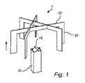
図1は、第1の電極、又はエミッタ10、及び、(矢印によって示された)流れの下流方向で、エミッタ10の一部分からオフセットで配置された少なくとも一部分を有する第2の電極、又はコレクタ20を備える装置1を示す。本実施形態にしたがうと、コレクタ20は、流れの方向に対して並行なそれぞれの平面でそれぞれ伸張する、例えば銅の3つの導電性薄板から形成され得る熱伝導性フランジ30と一体化される。
FIG. 1 shows a first electrode or
エミッタは、流れと横伸長の方向における垂直伸長又は最大高さh1、あるいは、流れの方向に垂直な又は少なくとも交差する方向で最大幅w1を有する棒10として形成され得る。本図面において示されるように、最大高さh1は、最大幅w2よりも大きく、したがって、流れの方向において伸長された形状を有する棒10を提供する。棒10は、流れの方向で尖っている1つ又はいくつかの先端部16でも提供され、これにより、可能性あるエミッタの放出点の数を増加している。
The emitter can be formed as a
動作の間、エミッタ10とコレクタ20は、少なくとも意図された流れ方向の方向で、エミッタ10とコレクタ20の間の電界を誘導するように(示されない)電圧ソースに接続され得、これにより、前述の方向に沿ってガス状流体の動きを誘発する。流体が装置1を通過するにつれて、流体によって運ばれた熱エネルギーは、フランジ30との熱接触の際、フランジ30に移行されて、装置1の周囲に結局は放散される。
During operation, the
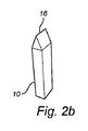
図2a〜図2dは、図1において示された装置1と類似した装置の第1の電極又はエミッタ10の異なる例を示す。図2aにおいて、エミッタ10は、流体がエミッタ10を通して流れるのを可能にする格子を形成するブリッジ11と接合部12を備え得る。エミッタ10は、(図1において矢印によって示された)意図された流れ方向に垂直な平面において横伸長部を有するのに対して、ブリッジ11の少なくとも1つの少なくとも一部分は、対応する幅w2よりも大きい最大の高さh1を有する。
2a-2d show different examples of a first electrode or
図2bは、別の例を開示し、ここにおいて、エミッタ10は、矩形の横断面と先端部を有する棒、又は柱として形成される。さらに、エミッタ10は、図2cにおいて示された複数の先端部を有する円筒形の棒として形成され得、及び/又は、図2dにおいて示された1つ、又はいくつかの針形状にされた本体を備え得る。
FIG. 2b discloses another example, where the
図3aと図3bは、図1と図2〜図2dを参照して記述された装置に対して同様に構成された装置1を開示する。装置1は、複数の熱伝導フランジ30を備え得、これらのそれぞれは、流れに対して並行で、装置10の共通中心軸Aから始まるそれぞれの平面で伸長する。さらに、カバー又は保護プレート40は、流れの方向と、フランジ30の頂端で(すなわちフランジの下流方向端で)交差する平面で配置され得る。カバー40は、装置1に渡って流れを通過させるためのスルーホールを有する円形のディスクとして形成され得る。コレクタ20は、フランジの頂端、好ましくはスルーホール近くに配置され得、例えば、図2aを参照して記述されたエミッタの構造に類似した網又は格子構造から形成され、又は、流れの方向と交差する平面で伸長するために配置された複数の線を備え得る。さらに、フランジ30は、エミッタ10を収容するように、装置1の長さ軸に沿って伸長する空間又は隙間を形成するように適応され得、これは例えば、フランジ30によって規定された空間又は隙間において少なくとも部分的に挿入されるように適応される(示されていない)棒として形成され得る。図3aが装置1のような斜視図を示すのに対し、図3bは、流れの方向で見られるような下からの図を示す。
3a and 3b disclose a similarly configured device 1 with respect to the devices described with reference to FIGS. 1 and 2-2d. The device 1 may include a plurality of thermal
図4は、別の実施形態による装置を開示し、これは、以前の図面を参照して議論された装置のうちの任意の1つのように同様に構成され得る。装置1は、(矢印によって示される)流れの方向に方向付けられたフランジ30の層状構造として形成され得るコレクタを備える。フランジは、例えば銅のような、熱伝導と電導材料の平面薄板から形成され得、これは、層状構造を形成するように曲げられ得る。フランジ30の上流端によってエミッタ10は配置され、フランジから距離dだけ離れて間隔をあけられ得る。エミッタ10は、例えば以前議論された格子構造を形成し得る、又は、1つ又はいくつかの線から形成され得る。エミッタ10とコレクタ20は、正の距離dだけ流れ方向で互いに離れて間隔をあけて配置され得る。間隔は、例えば、サポート構造によって、又は、エミッタ10とコレクタ20の間で配置された格子スペーサによって維持され得る。比較的狭い隙間dは、このような隙間が比較的高い電界を提供して、したがって流量に影響する電気流体力学的効果を向上し得るので望ましいかもしれない。
FIG. 4 discloses a device according to another embodiment, which may be similarly configured as any one of the devices discussed with reference to previous drawings. The device 1 comprises a collector that can be formed as a layered structure of
エミッタ10とコレクタ20は、エミッタ10とコレクタ20のうちの少なくとも1つから熱を移行、又は放散するように配置され得る、熱移行要素50に取り付けられ得る。図4において示されるように、熱移行要素50は、例えば金属の薄板から形成され得、(示されない)プリント基板において、受容構造に圧入、又はリフロー半田付けされ得る。動作の間、通過するガス状流体からの熱は、例えばコレクタ20からプリント基板に熱移行要素50を介して放散され得る。
The
いくつかの実施形態にしたがうと、本装置は、第1の電極及び/又は第2の電極の熱的に誘発された変形を和らげる又は防ぐように適合された懸垂構造を備え得る。変形構造とも呼ばれ得る懸垂構造は、例えば、電極の任意の1つの長さ方向、電極の少なくとも一部分、又は電極によって形成された構造に対して引張応力を適用するように適応され得る。図5aは、例えば本発明の実施形態にしたがった装置100におけるエミッタ110として作用する格子の変形構造又は懸垂構造115の一例を示す。この例において、格子は、以前に記述された実施形態によるブリッジ111と接合部112を備え得る。図5aにおいて示されるように、懸垂構造115は、流れ方向に対して標準の平面で湾曲したブリッジ111から構成され得る。湾曲した形状は、例えば、ブリッジ111の製造の間に形成され、又は装置100の使用の間に生じる熱的圧力によって誘発され得る。湾曲した形状は、熱が圧力を誘発した際により容易に変形させるように弱められた部分、例えば低減された幅を有する一部分を備え得る。
According to some embodiments, the device may comprise a suspension structure adapted to mitigate or prevent thermal-induced deformation of the first and / or second electrode. Suspended structures, which may also be referred to as deformed structures, can be adapted to apply tensile stress, for example, to any one length direction of the electrode, at least a portion of the electrode, or the structure formed by the electrode. FIG. 5a shows, for example, an example of a modified or suspended
格子の材料が上昇する温度とともに膨張するにつれて、変形構造126のブリッジ111は、ブリッジ111の長さ方向で作動する圧縮力によって圧縮され得る。長さ方向により第1の接合部と第2の接合部の間の伸長の方向が理解されるべきである。これにより、格子の横拡張は変形構造115によって和らげられて、熱的に誘発された圧力は低減されるので、変形構造115以外のエミッタ110は、熱膨張にも関わらずその元々の形状を保ち得る。しかしながら、変形構想115のブリッジ111上で作用する力はまた、又は代替的に、例えば、構造上で作用するねじりモーメント、又はトルクによって引き起こされ得ることが理解されるべきである。
As the grid material expands with increasing temperature, the
図5bは、図5aを参照して記述された同様の変形構造115を示し、ここにおいて、懸垂構造115は、エミッタ110に対して引張応力を適用するように適合される。しかしながら、装置100は、任意の1つ又はいくつかのエミッタ110、コレクタ120及び(示されない)サポート構造において配置された変形構造115で提供され得ることが理解される。
FIG. 5b shows a similar modified
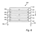
図6は、以前記述された実施形態のうちの任意の1つにしたがった3つの装置100の積み重ねを備えるファン組立200のような組立の横断面を示す。横断面は、(図6において矢印によって示される)流れの方向に沿ってとられる。各装置は、電子放出電極(エミッタ)110、電子収集電極(コレクタ)120、(示されない)熱伝導フランジ、流れの方向でエミッタ110とコレクタ120を別離するように配置された格子スペーサ130を備える。この実施形態にしたがうと、エミッタ110とコレクタ120は、例えばバルク材や表面被覆を形成する例えばPT、Au、又はステンレス鋼を備え得る。
FIG. 6 shows a cross section of an assembly, such as a
格子スペーサ130は、例えばエミッタ110とコレクタ120をサポートする格子として形成され得る。図6において示されるように、格子スペーサ130は、例えば溶接、半田付け、又は接着によってエミッタ110とコレクタ120の端部分が取り付けられる周辺枠を備え得る。代替的に又は付加的に、格子スペーサ130は、柱やスペーサ等のような他の間隔構造を備え得る。格子スペーサ130はまた、例えば、エミッタとコレクタの中央部分を支える付加的なブリッジ又は柱のような、1つ又はいくつかの間隔部材を備え得る。格子スペーサ130はまた、図5aと図5bを参照して記述された変形構造に類似した(示されない)変形構造115を備え得る。
The
エミッタ110及び/又はコレクタ120がサポート構造130に固く取り付けられる場合において、例えば屈曲や撓みのような変形、及び、破砕、切断又は緩められた接合部等のような損傷についての危険性は、変形構造115によって低減され得る。これにより、装置100の信頼性と耐用寿命が増加され得る。
When the
エミッタとコレクタの間隔は、格子スペーサ130のブリッジの高さによって決定され得、これはしたがって、エミッタ110とコレクタ120の間で誘導された電界の大きさを決定し得る。エミッタ110とコレクタ120の間の距離dは、例えば0.4mmと2mmの範囲内であり得る。
The distance between the emitter and collector can be determined by the height of the bridge of the
さらに、格子スペーサ130は、エミッタ110とコレクタ120の整列、及び/又は積み重ねの装置100の整列を促進するための整列構造を備え得る。
In addition, the
ファン組立200は第1の装置のエミッタ110と、第2の装置のコレクタ120の間の距離を維持するように配置されたステージスペーサ140で積み重ねられた構造も備え得る。積み重ね構造140はまた、積み重ねられた装置100の整列と組立を促進するための(図6において示されていない)整列構造142と、ことによると、組立200の構成要素間の任意の機械的負荷を低減するために、図5aと図5bを参照して記述された変形構造115、125を備え得る。
The
格子スペーサ130及び/又は積み重ね構造140は、例えば、Al2O3又はMacor(登録商標)のようなセラミック材料、プラスチック材料、又は任意の適切な電導材料を備え得る。
The
図6において示されるように、エミッタ110とコレクタ120は、電気コネクタ又はターミナル150によって(示されていない)外部電源に接続され得る。この方法で、電位差は、それぞれの装置100のエミッタ110とコレクタ120の間で適用され得る。電位差は、エミッタとコレクタ120のそれぞれの間、及びそれぞれを通した電子放出を促進して流体の動きを伝え得る電界を誘導し得る。さらに、エミッタ110及び/又はコレクタ120の間の電気接続150と外部電源は、積み重ね構造の機械的特徴によって及び/又は(図6において示されていない)電気接触部分129によって提供され得る。機械的特徴は、例えば、例えば焼結又は溶接の後に続く、例えば分配又はスクリーン印刷によって形成されることになる電気接続が形成されるのを可能にするように適応され得る。有利なことに、積み重ねのいくつか又は全てのエミッタ110及び/又はコレクタ120は、同じ製造ステップにおいて接続され得る。
As shown in FIG. 6, the
図7aとbは、時間tの関数として、本発明にしたがった装置100のエミッタ110に対して提供される電流iを示す。図7aにおいて、正電流は、第1の時間期間の間、適用されて維持されて、その後除去される。第2の時間期間の後に電力供給が再びスイッチオンされ、したがって第2のパルスを形成する。この手順を繰り返すことは、流体において存在し得る空間電荷を低減でき、任意のイオン化された粒子が再結合できるようにもし得る。
7a and 7b show the current i provided to the
応力緩和をさらに改善するために、パルス逆電流が、図7aを参照して記述されたパルス間で導入され得る。このようなプロセスの例は、図7bにおいて示され、ここにおいて、正のパルスは、負のパルスによって分離される。図7bにおいて示されるように、負のパルスは、正のパルスよりも大きな絶対値を有し得るが、正の流れ全体を可能にするために、より短い期間の間だけ持続する。逆のパルスによって正のパルスを分離するこの手順は、ことによるとエミッタ110及び/又はコレクタ120の汚染物質を除去するために、有利なことに応力緩和を改善し得る。
To further improve stress relaxation, pulse reverse currents can be introduced between the pulses described with reference to FIG. 7a. An example of such a process is shown in FIG. 7b, where the positive pulses are separated by the negative pulses. As shown in FIG. 7b, the negative pulse can have a larger absolute value than the positive pulse, but lasts only for a shorter period of time to allow for the entire positive flow. This procedure of separating the positive pulse by the reverse pulse can advantageously improve stress relaxation to remove contaminants in the
適用される電位差は、例えば装置の動作のモードに依存する。例えばインジェクションタイプモードの場合に、適用される電位差は、エミッタとコレクタの間の実際の距離に依存して250〜5000vの範囲において構成され得る。例えば伝導タイプモードの場合、適用される電位差は、エミッタとコレクタの間の同じ実際の距離について、10〜500vの範囲において構成され得る。 The potential difference applied depends, for example, on the mode of operation of the device. For example, in the case of injection type mode, the applied potential difference can be configured in the range of 250-5000v depending on the actual distance between the emitter and collector. For example, in the conduction type mode, the applied potential difference can be configured in the range of 10-500v for the same actual distance between the emitter and collector.
インジェクションタイプモード、又はイオンドラッグ(drag)モードは、装置の動作モードとして理解することができ、ここにおいて、エミッタでの比較的高い電界は、エミッタとガス状流体のインターフェースでガス状流体中に電子を注入させ、したがってガス状流体中で自由イオンのコロナを生成する。他方、伝導モードは、電界が実質的なコロナを作成するには低すぎるモードとして理解され得る。かえって、ガス流は、流体の流れを運ぶガス状流体中の不純物と粒子によって引き起こされる。 Injection type mode, or ion drag mode, can be understood as the operating mode of the device, where a relatively high electric field at the emitter is an electron in the gaseous fluid at the interface between the emitter and the gaseous fluid. Is injected, thus producing free ion corona in the gaseous fluid. Conduction mode, on the other hand, can be understood as a mode in which the electric field is too low to create a substantial corona. On the contrary, the gas flow is caused by impurities and particles in the gaseous fluid that carries the flow of the fluid.
一例において、外部電圧供給は、オゾンの形成を低減する方法で制御され得る。これは、例えば、最大の電位差又は電荷を制限することによって達成され得、これにより、電気ブレークスルーやスパークについての危険性を低減する。付加的に又は代替的に、ハウジング、コレクタ及び/又はフランジは、例えば触媒表面を用いてオゾンを分解するように適応され得る。 In one example, the external voltage supply can be controlled in a way that reduces the formation of ozone. This can be achieved, for example, by limiting the maximum potential difference or charge, thereby reducing the risk of electrical breakthroughs and sparks. Additional or alternative, housings, collectors and / or flanges can be adapted to decompose ozone, for example using catalyst surfaces.
上で概要を述べたように、図7aと図7bによって説明されたような、流体の流れを制御するための方法は、命令を記憶するコンピュータ読み取り可能な媒体を含むコンピュータプログラム製品の形態で分配されて使用されるコンピュータ実行可能な命令として具現化され得る。例を介して、コンピュータ読み取り可能な媒体は、コンピュータ記録媒体と通信媒体を備え得る。当業者によく知られるように、コンピュータ記録媒体は、コンピュータ読み取り可能な命令、データ構造、プログラムモジュール又は他のデータのような情報の記憶のための任意の方法、又は技術において実現される揮発性と不揮発性、取り外し可能と取り外し可能でない媒体の両方を含む。コンピュータ記録媒体(又は一時的でない媒体)は、RAM、ROM、EEPROM(登録商標)、フラッシュメモリ、又は他のメモリ技術、CD−ROM、デジタル多用途ディスク(DVD)、又は他の光学ディスク記憶装置、磁気カセット、磁気テープ、磁気ディスク記憶装置、又は他の磁気記憶装置を含むが、これらに限定されない。さらに、通信媒体(又は一時的な媒体)が、搬送波又は他の輸送メカニズムのような変調されたデータ信号においてコンピュータ読取可能な命令、データ構造、プログラムモジュール又は他のデータを典型的に具現化し、任意の情報配送媒体を含むことは、当業者に知られている。
以下に、出願当初の特許請求の範囲に記載の事項を、そのまま、付記しておく。
[1] ガス状流体の流れを制御するための装置(1)であって、
第1の電極(10)と、
第2の電極(20)と、ここで、前記第2の電極の少なくとも一部分は、前記流れの下流方向で前記第1の電極の少なくとも一部分からオフセットされ、前記第1、第2の電極は、電圧ソースと接続可能であり、
前記流れの方向に沿って方向付けられた平面に伸長し、前記ガス状流体から熱を放散するように適合された少なくとも1つの熱伝導性フランジ(30)とを備え、
前記第1の電極の少なくとも一部分は、前記流れの方向に並行な方向で最大高さ(h 1 )と、前記流れの方向に垂直な方向で最大幅(W 1 )を有する少なくとも一部分を備え、前記最大高さは、前記最大幅よりも大きい、装置。
[2] 前記第1の電極は、前記ガス状流体が前記第1の電極を通過することができるように配置された格子構造を形成するブリッジ(11)と接合部(12)を備え、前記第1の電極の一部分は、前記ブリッジのうちの少なくとも1つの一部を形成する、[1]に記載の装置。
[3] 前記第1の電極は、前記最大高さ(h1)に対応する高さと、前記最大幅(w1)に対応する幅を有する棒として形成される、[1]に記載の装置。
[4] 前記第1の電極は、前記流れの方向と交差する平面で円形又は多角形の横断面を有する棒として形成される、[3]に記載の装置。
[5] 前記棒は、前記流れの方向で尖っている少なくとも1つの鋭い先端部を備える、[3]又は[4]に記載の装置。
[6] 前記装置は、前記ガス状流体が前記第2の電極を通過できるように配置され、層状構造に配置された複数のフランジを備える、[1]乃至[5]のいずれか一項に記載の装置。
[7] 前記装置は、複数の相互に交差するフランジを備える、[1]乃至[5]のいずれか一項に記載の装置。
[8] 前記装置は、前記第1の電極の少なくとも一部分の周囲に少なくとも部分的に配置された複数のフランジを備える、[1]乃至[5]のいずれか一項に記載の装置。
[9] 前記第2の電極は、前記熱伝導性フランジに電気的に接続されている、[1]乃至[8]のいずれか一項に記載の装置。
[10] 前記第2の電極は、前記熱伝導性フランジと一体化して形成されている、[1]乃至[8]のいずれか一項に記載の装置。
[11] 前記流れの方向で、前記第1の電極から前記第2の電極を分離するサポート構造をさらに備える、[1]乃至[10]のいずれか一項に記載の装置。
[12] 前記流れの方向における前記第2の電極と前記第1の電極の間の距離は、0.4mm〜2mmの間である、[1]乃至[11]のいずれか一項に記載の装置。
[13] 前記第1の電極と前記第2の電極のうちの少なくとも1つは、前記流れの方向に垂直な平面で、前記第1の電極又は前記第2の電極においてそれぞれ熱的に誘発された変形を和らげるように配置された懸垂構造を備える、[1]乃至[12]のいずれか一項に記載の装置。
[14] 前記第1の電極と前記第2の電極のうちの少なくとも1つから基板に、及び/又は、前記基板の後部上に配置された構造に、熱を移行するように配置された熱伝導要素をさらに備える、[1]乃至[13]のいずれか一項に記載の装置。
[15] ガス状流体の流れを制御するための装置を製造する方法であって、
前記流れの方向に並行な方向で最大高さ(h 1 )と、前記流れの方向に垂直な方向で最大幅(W 1 )を有する少なくとも一部分を備え、前記最大高さは、前記最大幅よりも大きい第1の電極(110)を提供することと、
前記流れの方向に並行な平面で伸長するフランジとして形成された一部分を備える第2の電極(120)を提供することと、
前記流れの方向で前記第1の電極からオフセットされた前記第2の電極を配置することとを備える、
方法。
[16] 第1の電極及び/又は第2の電極は、金属を選択的に堆積することによって提供される、[15]に記載の方法。
[17] 第1の電極及び/又は第2の電極は、材料を金属基板から選択的に除去することによって提供される、[15]に記載の方法。
[18] ガス状流体の流れを制御する方法であって、
[1]乃至[14]のいずれか一項に記載の装置(100)を提供することと、
前記装置の前記第1の電極(110)と接触するガス状流体を提供することと、
前記第1の電極と前記第2の電極(120)の間の電位差を適用することとを備える、方法。
[19] 前記電位差を時間の関数として変化させるステップをさらに備える、[18]に記載の方法。
[20] 前記適用された電位差は、400〜4000vの範囲にある、[18]又は[19]に記載の方法。
[21] 前記適用された電位差は、100〜400vの範囲にある、[18]又は[19]に記載の方法。
As outlined above, methods for controlling fluid flow, as described by FIGS. 7a and 7b, are distributed in the form of computer program products that include computer-readable media for storing instructions. It can be embodied as a computer-executable instruction that is used. By way of example, a computer-readable medium may include a computer recording medium and a communication medium. As is well known to those skilled in the art, computer recording media are volatile realized in any method or technique for storing information such as computer-readable instructions, data structures, program modules or other data. And non-volatile, including both removable and non-removable media. Computer recording media (or non-temporary media) are RAM, ROM, EEPROM®, flash memory, or other memory technologies, CD-ROMs, digital versatile discs (DVDs), or other optical disc storage devices. , Includes, but is not limited to, magnetic cassettes, magnetic tapes, magnetic disk storage devices, or other magnetic storage devices. In addition, the communication medium (or temporary medium) typically embodies computer-readable instructions, data structures, program modules or other data in modulated data signals such as carriers or other transport mechanisms. It is known to those skilled in the art to include any information delivery medium.
Below, the matters described in the claims at the time of filing are added as they are.
[1] A device (1) for controlling the flow of gaseous fluid.
The first electrode (10) and
The second electrode (20), and here at least a portion of the second electrode, is offset from at least a portion of the first electrode in the downstream direction of the flow, and the first and second electrodes are Can be connected to a voltage source
With at least one thermally conductive flange (30) extending in a plane oriented along the direction of the flow and adapted to dissipate heat from the gaseous fluid.
At least a portion of the first electrode comprises at least a portion having a maximum height (h 1 ) in a direction parallel to the flow direction and a maximum width (W 1 ) in a direction perpendicular to the flow direction. A device in which the maximum height is greater than the maximum width.
[2] The first electrode includes a bridge (11) and a joint (12) forming a lattice structure arranged so that the gaseous fluid can pass through the first electrode. The device according to [1], wherein a part of the first electrode forms at least one part of the bridge.
[3] The apparatus according to [1], wherein the first electrode is formed as a rod having a height corresponding to the maximum height (h1) and a width corresponding to the maximum width (w1).
[4] The apparatus according to [3], wherein the first electrode is formed as a rod having a circular or polygonal cross section in a plane intersecting the direction of the flow.
[5] The device according to [3] or [4], wherein the rod comprises at least one sharp tip pointed in the direction of the flow.
[6] The device according to any one of [1] to [5], wherein the device is arranged so that the gaseous fluid can pass through the second electrode, and includes a plurality of flanges arranged in a layered structure. The device described.
[7] The device according to any one of [1] to [5], wherein the device includes a plurality of flanges that intersect each other.
[8] The device according to any one of [1] to [5], wherein the device includes a plurality of flanges arranged at least partially around at least a part of the first electrode.
[9] The device according to any one of [1] to [8], wherein the second electrode is electrically connected to the heat conductive flange.
[10] The apparatus according to any one of [1] to [8], wherein the second electrode is formed integrally with the heat conductive flange.
[11] The apparatus according to any one of [1] to [10], further comprising a support structure for separating the second electrode from the first electrode in the flow direction.
[12] The item according to any one of [1] to [11], wherein the distance between the second electrode and the first electrode in the flow direction is between 0.4 mm and 2 mm. apparatus.
[13] At least one of the first electrode and the second electrode is thermally induced in the first electrode or the second electrode, respectively, in a plane perpendicular to the flow direction. The apparatus according to any one of [1] to [12], comprising a suspension structure arranged so as to soften the deformation.
[14] Heat arranged to transfer heat from at least one of the first electrode and the second electrode to a structure arranged on the substrate and / or on the rear portion of the substrate. The apparatus according to any one of [1] to [13], further comprising a conductive element.
[15] A method of manufacturing a device for controlling the flow of a gaseous fluid.
It comprises at least a portion having a maximum height (h 1 ) in a direction parallel to the flow direction and a maximum width (W 1 ) in a direction perpendicular to the flow direction, the maximum height being greater than or equal to the maximum width. To provide a first electrode (110) that is also large,
To provide a second electrode (120) comprising a portion formed as a flange extending in a plane parallel to the direction of flow.
It comprises arranging the second electrode offset from the first electrode in the direction of flow.
Method.
[16] The method of [15], wherein the first electrode and / or the second electrode is provided by selectively depositing a metal.
[17] The method of [15], wherein the first electrode and / or the second electrode is provided by selectively removing the material from the metal substrate.
[18] A method of controlling the flow of gaseous fluid.
To provide the device (100) according to any one of [1] to [14].
To provide a gaseous fluid in contact with the first electrode (110) of the device.
A method comprising applying a potential difference between the first electrode and the second electrode (120).
[19] The method according to [18], further comprising a step of changing the potential difference as a function of time.
[20] The method according to [18] or [19], wherein the applied potential difference is in the range of 400 to 4000v.
[21] The method according to [18] or [19], wherein the applied potential difference is in the range of 100 to 400v.
Claims (20)
第1の電極(10)と、
第2の電極(20)と、ここで、前記第2の電極の少なくとも一部分は、前記流れの下流方向で前記第1の電極の少なくとも一部分からオフセットされ、前記第1、第2の電極は、電圧ソースと接続可能であり、
前記流れの方向に沿って方向付けられた平面に伸長し、前記ガス状流体から熱を放散するように適合された複数の熱伝導性フランジ(30)と、ここで、前記複数の熱伝導性フランジは前記第1の電極の少なくとも一部分の周囲に少なくとも部分的に配置されており、を備え、
前記第1の電極の少なくとも一部分は、前記流れの方向に並行な方向で最大高さ(h1)と、前記流れの方向に垂直な方向で最大幅(W1)を有し、前記最大高さは、前記最大幅よりも大きい、装置。 A device (1) for controlling the flow of gaseous fluid.
The first electrode (10) and
The second electrode (20), and here at least a portion of the second electrode, is offset from at least a portion of the first electrode in the downstream direction of the flow, and the first and second electrodes are Can be connected to a voltage source
A plurality of thermally conductive flanges (30) extending into a plane oriented along the direction of the flow and adapted to dissipate heat from the gaseous fluid , and here, the plurality of thermally conductive flanges. The flange is at least partially disposed around at least a portion of the first electrode and comprises.
Wherein at least a portion of the first electrode, the maximum height (h 1) in a direction parallel to the direction of the flow, have a maximum width (W 1) in a direction perpendicular to the direction of the flow, the maximum height The device is larger than the maximum width.
前記流れの方向に並行な方向で最大高さ(h1)と、前記流れの方向に垂直な方向で最大幅(W1)を有する少なくとも一部分を備え、前記最大高さは、前記最大幅よりも大きい第1の電極(110)を提供することと、
前記流れの方向に並行な平面で伸長するフランジとして形成された一部分を備える第2の電極(120)を提供することと、
前記流れの方向に沿って方向付けられた平面に伸長し、前記ガス状流体から熱を放散するように適合された複数の熱伝導性フランジ(30)を提供することと、ここで、前記複数の熱伝導性フランジは前記第1の電極の少なくとも一部分の周囲に少なくとも部分的に配置されており、及び
前記流れの方向で前記第1の電極からオフセットして前記第2の電極を配置することと、を備える、方法。 A method of manufacturing a device for controlling the flow of gaseous fluids.
It comprises at least a portion having a maximum height (h 1 ) in a direction parallel to the flow direction and a maximum width (W 1 ) in a direction perpendicular to the flow direction, the maximum height being greater than or equal to the maximum width. To provide a first electrode (110) that is also large,
To provide a second electrode (120) comprising a portion formed as a flange extending in a plane parallel to the direction of flow.
To provide a plurality of thermally conductive flanges (30) extending in a plane oriented along the direction of the flow and adapted to dissipate heat from the gaseous fluid, wherein the plurality. it is thermally conductive flange disposed at least around a portion being at least partially disposed, and the second electrode offset from said first electrode in the direction of the flow of said first electrode And, how to.
請求項1乃至13のいずれか一項に記載の装置(100)を提供することと、
前記装置の前記第1の電極(110)と接触するガス状流体を提供することと、
前記第1の電極と前記第2の電極(120)の間に電位差を適用することと、を備える、方法。 A method of controlling the flow of gaseous fluids
Providing an apparatus according (100) to any one of claims 1 to 1 3,
To provide a gaseous fluid in contact with the first electrode (110) of the device.
And a applying a potential difference between said first electrode and the second electrode (120), method.
Applications Claiming Priority (3)
| Application Number | Priority Date | Filing Date | Title |
|---|---|---|---|
| SE1550715-5 | 2015-06-03 | ||
| SE1550715A SE539310C2 (en) | 2015-06-03 | 2015-06-03 | Microfluidic fan |
| PCT/SE2016/050466 WO2016195571A1 (en) | 2015-06-03 | 2016-05-20 | Microfluidic fan |
Publications (2)
| Publication Number | Publication Date |
|---|---|
| JP2018525966A JP2018525966A (en) | 2018-09-06 |
| JP6859331B2 true JP6859331B2 (en) | 2021-04-14 |
Family
ID=57441314
Family Applications (1)
| Application Number | Title | Priority Date | Filing Date |
|---|---|---|---|
| JP2018515757A Active JP6859331B2 (en) | 2015-06-03 | 2016-05-20 | Microfluidic fan |
Country Status (8)
| Country | Link |
|---|---|
| US (1) | US11078894B2 (en) |
| EP (1) | EP3304590B1 (en) |
| JP (1) | JP6859331B2 (en) |
| KR (1) | KR102563941B1 (en) |
| CN (1) | CN107924895B (en) |
| SE (1) | SE539310C2 (en) |
| TW (1) | TWI732763B (en) |
| WO (1) | WO2016195571A1 (en) |
Family Cites Families (22)
| Publication number | Priority date | Publication date | Assignee | Title |
|---|---|---|---|---|
| US4227894A (en) | 1978-10-10 | 1980-10-14 | Proynoff John D | Ion generator or electrostatic environmental conditioner |
| US4504446A (en) * | 1981-11-25 | 1985-03-12 | Opt Systems | Ozone generator |
| US4689056A (en) | 1983-11-23 | 1987-08-25 | Nippon Soken, Inc. | Air cleaner using ionic wind |
| US5964997A (en) | 1997-03-21 | 1999-10-12 | Sarnoff Corporation | Balanced asymmetric electronic pulse patterns for operating electrode-based pumps |
| US6544485B1 (en) * | 2001-01-29 | 2003-04-08 | Sharper Image Corporation | Electro-kinetic device with enhanced anti-microorganism capability |
| JP2000222072A (en) | 1999-02-01 | 2000-08-11 | Shingijutsu Management:Kk | Cooling device |
| AU2002341621A1 (en) * | 2001-09-10 | 2003-03-24 | Meso Scale Technologies, Llc | Methods, reagents, kits and apparatus for protein function analysis |
| US7909583B2 (en) | 2004-03-23 | 2011-03-22 | Osaka Vacuum, Ltd. | Pump apparatus and pump unit thereof |
| KR20070108880A (en) | 2005-01-24 | 2007-11-13 | 손 마이크로 테크놀로지스, 인코포레이티드 | Electro-hydrodynamic pump and cooling apparatus comprising an electro-hydrodynamic pump |
| US20100177519A1 (en) * | 2006-01-23 | 2010-07-15 | Schlitz Daniel J | Electro-hydrodynamic gas flow led cooling system |
| WO2007112763A1 (en) * | 2006-04-03 | 2007-10-11 | Aureola Swedish Engineering Ab | Method and apparatus for cooling and ventilation |
| US20080060794A1 (en) | 2006-09-12 | 2008-03-13 | Neng Tyi Precision Industries Co., Ltd. | Heat sink device generating an ionic wind |
| EP2126956A1 (en) * | 2007-01-23 | 2009-12-02 | Ventiva, Inc. | Contoured electrodes for an electrostatic gas pump |
| US20100116460A1 (en) * | 2008-11-10 | 2010-05-13 | Tessera, Inc. | Spatially distributed ventilation boundary using electrohydrodynamic fluid accelerators |
| US20100155025A1 (en) * | 2008-12-19 | 2010-06-24 | Tessera, Inc. | Collector electrodes and ion collecting surfaces for electrohydrodynamic fluid accelerators |
| US20110094710A1 (en) * | 2009-10-23 | 2011-04-28 | Ventiva, Inc. | Redundant emitter electrodes in an ion wind fan |
| US20110116206A1 (en) | 2009-11-16 | 2011-05-19 | Mentornics, Inc. | Cooling of electronic components using self-propelled ionic wind |
| US20120007742A1 (en) | 2010-07-09 | 2012-01-12 | Ventiva, Inc. | Consumer electronics device having replaceable ion wind fan |
| JP5423625B2 (en) | 2010-09-09 | 2014-02-19 | 株式会社デンソー | Cooling device using EHD fluid |
| JP2014212625A (en) * | 2013-04-18 | 2014-11-13 | 株式会社デンソー | EHD pump |
| JP6048292B2 (en) | 2013-04-18 | 2016-12-21 | 株式会社デンソー | EHD pump |
| US20150114608A1 (en) * | 2013-10-30 | 2015-04-30 | Forcecon Technology Co., Ltd. | Electrostatic air-cooled heat sink |
-
2015
- 2015-06-03 SE SE1550715A patent/SE539310C2/en unknown
-
2016
- 2016-05-20 EP EP16803851.1A patent/EP3304590B1/en active Active
- 2016-05-20 US US15/578,643 patent/US11078894B2/en active Active
- 2016-05-20 KR KR1020187000191A patent/KR102563941B1/en active IP Right Grant
- 2016-05-20 WO PCT/SE2016/050466 patent/WO2016195571A1/en active Application Filing
- 2016-05-20 CN CN201680032038.4A patent/CN107924895B/en active Active
- 2016-05-20 JP JP2018515757A patent/JP6859331B2/en active Active
- 2016-05-30 TW TW105116921A patent/TWI732763B/en active
Also Published As
| Publication number | Publication date |
|---|---|
| US11078894B2 (en) | 2021-08-03 |
| KR20180021778A (en) | 2018-03-05 |
| EP3304590B1 (en) | 2021-02-17 |
| TW201710603A (en) | 2017-03-16 |
| KR102563941B1 (en) | 2023-08-04 |
| US20180135613A1 (en) | 2018-05-17 |
| JP2018525966A (en) | 2018-09-06 |
| SE1550715A1 (en) | 2016-12-04 |
| CN107924895B (en) | 2021-05-11 |
| EP3304590A4 (en) | 2019-05-08 |
| EP3304590A1 (en) | 2018-04-11 |
| TWI732763B (en) | 2021-07-11 |
| SE539310C2 (en) | 2017-06-27 |
| CN107924895A (en) | 2018-04-17 |
| WO2016195571A1 (en) | 2016-12-08 |
Similar Documents
| Publication | Publication Date | Title |
|---|---|---|
| US10943849B2 (en) | Microfluidic array | |
| EP3090175B1 (en) | Microfluidic device | |
| JP6859331B2 (en) | Microfluidic fan | |
| JP6794456B2 (en) | Electrohydrodynamic control device | |
| JP7473672B2 (en) | Thermally isolated trapping feature for ion implantation systems - Patents.com | |
| RU2442746C2 (en) | Nanodevice and method | |
| US20110116205A1 (en) | Collector electrodes for an ion wind fan | |
| JP5227281B2 (en) | Electrostatic atomizer | |
| CN101662120B (en) | Ionic wind radiating device | |
| EP3428981A1 (en) | Thermoelectric conversion module | |
| KR20160132907A (en) | Connector for electrically contacting arresters of an electrochemical cell |
Legal Events
| Date | Code | Title | Description |
|---|---|---|---|
| A621 | Written request for application examination |
Free format text: JAPANESE INTERMEDIATE CODE: A621 Effective date: 20190516 |
|
| A977 | Report on retrieval |
Free format text: JAPANESE INTERMEDIATE CODE: A971007 Effective date: 20200624 |
|
| A131 | Notification of reasons for refusal |
Free format text: JAPANESE INTERMEDIATE CODE: A131 Effective date: 20200630 |
|
| A601 | Written request for extension of time |
Free format text: JAPANESE INTERMEDIATE CODE: A601 Effective date: 20200930 |
|
| A521 | Request for written amendment filed |
Free format text: JAPANESE INTERMEDIATE CODE: A523 Effective date: 20201019 |
|
| TRDD | Decision of grant or rejection written | ||
| A01 | Written decision to grant a patent or to grant a registration (utility model) |
Free format text: JAPANESE INTERMEDIATE CODE: A01 Effective date: 20210224 |
|
| A61 | First payment of annual fees (during grant procedure) |
Free format text: JAPANESE INTERMEDIATE CODE: A61 Effective date: 20210325 |
|
| R150 | Certificate of patent or registration of utility model |
Ref document number: 6859331 Country of ref document: JP Free format text: JAPANESE INTERMEDIATE CODE: R150 |
|
| R250 | Receipt of annual fees |
Free format text: JAPANESE INTERMEDIATE CODE: R250 |