JP6857433B2 - Post-treatment of molten carbonate fuel cell anode exhaust for carbon dioxide capture - Google Patents
Post-treatment of molten carbonate fuel cell anode exhaust for carbon dioxide capture Download PDFInfo
- Publication number
- JP6857433B2 JP6857433B2 JP2018555215A JP2018555215A JP6857433B2 JP 6857433 B2 JP6857433 B2 JP 6857433B2 JP 2018555215 A JP2018555215 A JP 2018555215A JP 2018555215 A JP2018555215 A JP 2018555215A JP 6857433 B2 JP6857433 B2 JP 6857433B2
- Authority
- JP
- Japan
- Prior art keywords
- gas
- anode
- fuel cell
- stream
- hydrogen
- Prior art date
- Legal status (The legal status is an assumption and is not a legal conclusion. Google has not performed a legal analysis and makes no representation as to the accuracy of the status listed.)
- Active
Links
- 239000000446 fuel Substances 0.000 title claims description 71
- CURLTUGMZLYLDI-UHFFFAOYSA-N Carbon dioxide Chemical compound O=C=O CURLTUGMZLYLDI-UHFFFAOYSA-N 0.000 title description 4
- BVKZGUZCCUSVTD-UHFFFAOYSA-L Carbonate Chemical compound [O-]C([O-])=O BVKZGUZCCUSVTD-UHFFFAOYSA-L 0.000 title description 2
- 229910002092 carbon dioxide Inorganic materials 0.000 title description 2
- 239000001569 carbon dioxide Substances 0.000 title description 2
- 239000007789 gas Substances 0.000 claims description 122
- 239000001257 hydrogen Substances 0.000 claims description 70
- 229910052739 hydrogen Inorganic materials 0.000 claims description 70
- UFHFLCQGNIYNRP-UHFFFAOYSA-N Hydrogen Chemical compound [H][H] UFHFLCQGNIYNRP-UHFFFAOYSA-N 0.000 claims description 62
- 230000001590 oxidative effect Effects 0.000 claims description 55
- 238000000034 method Methods 0.000 claims description 35
- XLYOFNOQVPJJNP-UHFFFAOYSA-N water Substances O XLYOFNOQVPJJNP-UHFFFAOYSA-N 0.000 claims description 32
- 239000000112 cooling gas Substances 0.000 claims description 29
- 239000007800 oxidant agent Substances 0.000 claims description 20
- MHAJPDPJQMAIIY-UHFFFAOYSA-N Hydrogen peroxide Chemical compound OO MHAJPDPJQMAIIY-UHFFFAOYSA-N 0.000 claims description 19
- 238000007254 oxidation reaction Methods 0.000 claims description 18
- 230000003647 oxidation Effects 0.000 claims description 14
- 238000006243 chemical reaction Methods 0.000 claims description 10
- 238000001816 cooling Methods 0.000 claims description 8
- 238000007599 discharging Methods 0.000 claims description 8
- 150000002431 hydrogen Chemical class 0.000 claims description 7
- UGFAIRIUMAVXCW-UHFFFAOYSA-N Carbon monoxide Chemical compound [O+]#[C-] UGFAIRIUMAVXCW-UHFFFAOYSA-N 0.000 description 73
- 229910002091 carbon monoxide Inorganic materials 0.000 description 73
- 238000001179 sorption measurement Methods 0.000 description 12
- 238000002955 isolation Methods 0.000 description 10
- QVGXLLKOCUKJST-UHFFFAOYSA-N atomic oxygen Chemical compound [O] QVGXLLKOCUKJST-UHFFFAOYSA-N 0.000 description 7
- 239000001301 oxygen Substances 0.000 description 7
- 229910052760 oxygen Inorganic materials 0.000 description 7
- 238000000926 separation method Methods 0.000 description 6
- 239000006227 byproduct Substances 0.000 description 4
- VNWKTOKETHGBQD-UHFFFAOYSA-N methane Chemical compound C VNWKTOKETHGBQD-UHFFFAOYSA-N 0.000 description 4
- VUZPPFZMUPKLLV-UHFFFAOYSA-N methane;hydrate Chemical compound C.O VUZPPFZMUPKLLV-UHFFFAOYSA-N 0.000 description 4
- 230000004048 modification Effects 0.000 description 4
- 238000012986 modification Methods 0.000 description 4
- 239000003054 catalyst Substances 0.000 description 3
- 239000003245 coal Substances 0.000 description 3
- IJGRMHOSHXDMSA-UHFFFAOYSA-N Atomic nitrogen Chemical compound N#N IJGRMHOSHXDMSA-UHFFFAOYSA-N 0.000 description 2
- 238000006477 desulfuration reaction Methods 0.000 description 2
- 230000023556 desulfurization Effects 0.000 description 2
- 239000003345 natural gas Substances 0.000 description 2
- BASFCYQUMIYNBI-UHFFFAOYSA-N platinum Chemical compound [Pt] BASFCYQUMIYNBI-UHFFFAOYSA-N 0.000 description 2
- 238000012805 post-processing Methods 0.000 description 2
- 238000011084 recovery Methods 0.000 description 2
- 239000000126 substance Substances 0.000 description 2
- 208000001408 Carbon monoxide poisoning Diseases 0.000 description 1
- 238000001311 chemical methods and process Methods 0.000 description 1
- 229910017052 cobalt Inorganic materials 0.000 description 1
- 239000010941 cobalt Substances 0.000 description 1
- 239000012141 concentrate Substances 0.000 description 1
- 239000002826 coolant Substances 0.000 description 1
- 229910052802 copper Inorganic materials 0.000 description 1
- 239000010949 copper Substances 0.000 description 1
- 238000013461 design Methods 0.000 description 1
- 238000003795 desorption Methods 0.000 description 1
- PCHJSUWPFVWCPO-UHFFFAOYSA-N gold Chemical compound [Au] PCHJSUWPFVWCPO-UHFFFAOYSA-N 0.000 description 1
- 229910052737 gold Inorganic materials 0.000 description 1
- 239000010931 gold Substances 0.000 description 1
- 239000005431 greenhouse gas Substances 0.000 description 1
- -1 hydrogen ions Chemical class 0.000 description 1
- 238000002347 injection Methods 0.000 description 1
- 239000007924 injection Substances 0.000 description 1
- 238000007689 inspection Methods 0.000 description 1
- 239000000463 material Substances 0.000 description 1
- 239000012528 membrane Substances 0.000 description 1
- 229910052757 nitrogen Inorganic materials 0.000 description 1
- 229910000510 noble metal Inorganic materials 0.000 description 1
- 238000013021 overheating Methods 0.000 description 1
- 229910052697 platinum Inorganic materials 0.000 description 1
- 238000012545 processing Methods 0.000 description 1
- 238000010926 purge Methods 0.000 description 1
- 239000011973 solid acid Substances 0.000 description 1
- 238000006467 substitution reaction Methods 0.000 description 1
- 238000011144 upstream manufacturing Methods 0.000 description 1
- 239000002699 waste material Substances 0.000 description 1
Images


Classifications
-
- H—ELECTRICITY
- H01—ELECTRIC ELEMENTS
- H01M—PROCESSES OR MEANS, e.g. BATTERIES, FOR THE DIRECT CONVERSION OF CHEMICAL ENERGY INTO ELECTRICAL ENERGY
- H01M8/00—Fuel cells; Manufacture thereof
- H01M8/06—Combination of fuel cells with means for production of reactants or for treatment of residues
- H01M8/0662—Treatment of gaseous reactants or gaseous residues, e.g. cleaning
- H01M8/0668—Removal of carbon monoxide or carbon dioxide
-
- B—PERFORMING OPERATIONS; TRANSPORTING
- B01—PHYSICAL OR CHEMICAL PROCESSES OR APPARATUS IN GENERAL
- B01D—SEPARATION
- B01D53/00—Separation of gases or vapours; Recovering vapours of volatile solvents from gases; Chemical or biological purification of waste gases, e.g. engine exhaust gases, smoke, fumes, flue gases, aerosols
- B01D53/02—Separation of gases or vapours; Recovering vapours of volatile solvents from gases; Chemical or biological purification of waste gases, e.g. engine exhaust gases, smoke, fumes, flue gases, aerosols by adsorption, e.g. preparative gas chromatography
- B01D53/04—Separation of gases or vapours; Recovering vapours of volatile solvents from gases; Chemical or biological purification of waste gases, e.g. engine exhaust gases, smoke, fumes, flue gases, aerosols by adsorption, e.g. preparative gas chromatography with stationary adsorbents
- B01D53/047—Pressure swing adsorption
-
- B—PERFORMING OPERATIONS; TRANSPORTING
- B01—PHYSICAL OR CHEMICAL PROCESSES OR APPARATUS IN GENERAL
- B01D—SEPARATION
- B01D53/00—Separation of gases or vapours; Recovering vapours of volatile solvents from gases; Chemical or biological purification of waste gases, e.g. engine exhaust gases, smoke, fumes, flue gases, aerosols
- B01D53/26—Drying gases or vapours
- B01D53/263—Drying gases or vapours by absorption
-
- B—PERFORMING OPERATIONS; TRANSPORTING
- B01—PHYSICAL OR CHEMICAL PROCESSES OR APPARATUS IN GENERAL
- B01D—SEPARATION
- B01D53/00—Separation of gases or vapours; Recovering vapours of volatile solvents from gases; Chemical or biological purification of waste gases, e.g. engine exhaust gases, smoke, fumes, flue gases, aerosols
- B01D53/32—Separation of gases or vapours; Recovering vapours of volatile solvents from gases; Chemical or biological purification of waste gases, e.g. engine exhaust gases, smoke, fumes, flue gases, aerosols by electrical effects other than those provided for in group B01D61/00
- B01D53/326—Separation of gases or vapours; Recovering vapours of volatile solvents from gases; Chemical or biological purification of waste gases, e.g. engine exhaust gases, smoke, fumes, flue gases, aerosols by electrical effects other than those provided for in group B01D61/00 in electrochemical cells
-
- H—ELECTRICITY
- H01—ELECTRIC ELEMENTS
- H01M—PROCESSES OR MEANS, e.g. BATTERIES, FOR THE DIRECT CONVERSION OF CHEMICAL ENERGY INTO ELECTRICAL ENERGY
- H01M8/00—Fuel cells; Manufacture thereof
- H01M8/04—Auxiliary arrangements, e.g. for control of pressure or for circulation of fluids
- H01M8/04007—Auxiliary arrangements, e.g. for control of pressure or for circulation of fluids related to heat exchange
- H01M8/04014—Heat exchange using gaseous fluids; Heat exchange by combustion of reactants
- H01M8/04022—Heating by combustion
-
- H—ELECTRICITY
- H01—ELECTRIC ELEMENTS
- H01M—PROCESSES OR MEANS, e.g. BATTERIES, FOR THE DIRECT CONVERSION OF CHEMICAL ENERGY INTO ELECTRICAL ENERGY
- H01M8/00—Fuel cells; Manufacture thereof
- H01M8/04—Auxiliary arrangements, e.g. for control of pressure or for circulation of fluids
- H01M8/04082—Arrangements for control of reactant parameters, e.g. pressure or concentration
- H01M8/04089—Arrangements for control of reactant parameters, e.g. pressure or concentration of gaseous reactants
- H01M8/04097—Arrangements for control of reactant parameters, e.g. pressure or concentration of gaseous reactants with recycling of the reactants
-
- H—ELECTRICITY
- H01—ELECTRIC ELEMENTS
- H01M—PROCESSES OR MEANS, e.g. BATTERIES, FOR THE DIRECT CONVERSION OF CHEMICAL ENERGY INTO ELECTRICAL ENERGY
- H01M8/00—Fuel cells; Manufacture thereof
- H01M8/04—Auxiliary arrangements, e.g. for control of pressure or for circulation of fluids
- H01M8/04082—Arrangements for control of reactant parameters, e.g. pressure or concentration
- H01M8/04089—Arrangements for control of reactant parameters, e.g. pressure or concentration of gaseous reactants
- H01M8/04119—Arrangements for control of reactant parameters, e.g. pressure or concentration of gaseous reactants with simultaneous supply or evacuation of electrolyte; Humidifying or dehumidifying
- H01M8/04156—Arrangements for control of reactant parameters, e.g. pressure or concentration of gaseous reactants with simultaneous supply or evacuation of electrolyte; Humidifying or dehumidifying with product water removal
- H01M8/04164—Arrangements for control of reactant parameters, e.g. pressure or concentration of gaseous reactants with simultaneous supply or evacuation of electrolyte; Humidifying or dehumidifying with product water removal by condensers, gas-liquid separators or filters
-
- H—ELECTRICITY
- H01—ELECTRIC ELEMENTS
- H01M—PROCESSES OR MEANS, e.g. BATTERIES, FOR THE DIRECT CONVERSION OF CHEMICAL ENERGY INTO ELECTRICAL ENERGY
- H01M8/00—Fuel cells; Manufacture thereof
- H01M8/04—Auxiliary arrangements, e.g. for control of pressure or for circulation of fluids
- H01M8/04298—Processes for controlling fuel cells or fuel cell systems
- H01M8/04694—Processes for controlling fuel cells or fuel cell systems characterised by variables to be controlled
- H01M8/04828—Humidity; Water content
-
- H—ELECTRICITY
- H01—ELECTRIC ELEMENTS
- H01M—PROCESSES OR MEANS, e.g. BATTERIES, FOR THE DIRECT CONVERSION OF CHEMICAL ENERGY INTO ELECTRICAL ENERGY
- H01M8/00—Fuel cells; Manufacture thereof
- H01M8/06—Combination of fuel cells with means for production of reactants or for treatment of residues
- H01M8/0606—Combination of fuel cells with means for production of reactants or for treatment of residues with means for production of gaseous reactants
- H01M8/0612—Combination of fuel cells with means for production of reactants or for treatment of residues with means for production of gaseous reactants from carbon-containing material
-
- H—ELECTRICITY
- H01—ELECTRIC ELEMENTS
- H01M—PROCESSES OR MEANS, e.g. BATTERIES, FOR THE DIRECT CONVERSION OF CHEMICAL ENERGY INTO ELECTRICAL ENERGY
- H01M8/00—Fuel cells; Manufacture thereof
- H01M8/06—Combination of fuel cells with means for production of reactants or for treatment of residues
- H01M8/0662—Treatment of gaseous reactants or gaseous residues, e.g. cleaning
- H01M8/0681—Reactant purification by the use of electrochemical cells
-
- H—ELECTRICITY
- H01—ELECTRIC ELEMENTS
- H01M—PROCESSES OR MEANS, e.g. BATTERIES, FOR THE DIRECT CONVERSION OF CHEMICAL ENERGY INTO ELECTRICAL ENERGY
- H01M8/00—Fuel cells; Manufacture thereof
- H01M8/24—Grouping of fuel cells, e.g. stacking of fuel cells
- H01M8/249—Grouping of fuel cells, e.g. stacking of fuel cells comprising two or more groupings of fuel cells, e.g. modular assemblies
-
- B—PERFORMING OPERATIONS; TRANSPORTING
- B01—PHYSICAL OR CHEMICAL PROCESSES OR APPARATUS IN GENERAL
- B01D—SEPARATION
- B01D2256/00—Main component in the product gas stream after treatment
- B01D2256/22—Carbon dioxide
-
- B—PERFORMING OPERATIONS; TRANSPORTING
- B01—PHYSICAL OR CHEMICAL PROCESSES OR APPARATUS IN GENERAL
- B01D—SEPARATION
- B01D2257/00—Components to be removed
- B01D2257/10—Single element gases other than halogens
- B01D2257/108—Hydrogen
-
- B—PERFORMING OPERATIONS; TRANSPORTING
- B01—PHYSICAL OR CHEMICAL PROCESSES OR APPARATUS IN GENERAL
- B01D—SEPARATION
- B01D2257/00—Components to be removed
- B01D2257/80—Water
-
- H—ELECTRICITY
- H01—ELECTRIC ELEMENTS
- H01M—PROCESSES OR MEANS, e.g. BATTERIES, FOR THE DIRECT CONVERSION OF CHEMICAL ENERGY INTO ELECTRICAL ENERGY
- H01M8/00—Fuel cells; Manufacture thereof
- H01M8/14—Fuel cells with fused electrolytes
- H01M2008/147—Fuel cells with molten carbonates
-
- Y—GENERAL TAGGING OF NEW TECHNOLOGICAL DEVELOPMENTS; GENERAL TAGGING OF CROSS-SECTIONAL TECHNOLOGIES SPANNING OVER SEVERAL SECTIONS OF THE IPC; TECHNICAL SUBJECTS COVERED BY FORMER USPC CROSS-REFERENCE ART COLLECTIONS [XRACs] AND DIGESTS
- Y02—TECHNOLOGIES OR APPLICATIONS FOR MITIGATION OR ADAPTATION AGAINST CLIMATE CHANGE
- Y02C—CAPTURE, STORAGE, SEQUESTRATION OR DISPOSAL OF GREENHOUSE GASES [GHG]
- Y02C20/00—Capture or disposal of greenhouse gases
- Y02C20/40—Capture or disposal of greenhouse gases of CO2
-
- Y—GENERAL TAGGING OF NEW TECHNOLOGICAL DEVELOPMENTS; GENERAL TAGGING OF CROSS-SECTIONAL TECHNOLOGIES SPANNING OVER SEVERAL SECTIONS OF THE IPC; TECHNICAL SUBJECTS COVERED BY FORMER USPC CROSS-REFERENCE ART COLLECTIONS [XRACs] AND DIGESTS
- Y02—TECHNOLOGIES OR APPLICATIONS FOR MITIGATION OR ADAPTATION AGAINST CLIMATE CHANGE
- Y02E—REDUCTION OF GREENHOUSE GAS [GHG] EMISSIONS, RELATED TO ENERGY GENERATION, TRANSMISSION OR DISTRIBUTION
- Y02E60/00—Enabling technologies; Technologies with a potential or indirect contribution to GHG emissions mitigation
- Y02E60/30—Hydrogen technology
- Y02E60/50—Fuel cells
Description
本開示は、直接溶融炭酸塩型燃料電池(「DFC」)内の二酸化炭素(CO2)分離に関する。特に、本開示は、DFCからCO2リッチアノード排気流を受け取り、隔離のためにCO2を濃縮する電気化学水素分離装置(「EHS」)に関する。 The present disclosure relates to the separation of carbon dioxide (CO 2 ) in a direct molten carbonate fuel cell (“DFC”). In particular, the present disclosure relates to an electrochemical hydrogen separator (“EHS”) that receives a CO 2 rich anode exhaust stream from a DFC and concentrates CO 2 for isolation.
DFC用のCO2分離システムでは、CO2リッチアノード排気流はさらに、水蒸気と、主に水素および一酸化炭素(CO)を含む未使用燃料とを含む。排気流を隔離または使用のためにCO2回収(すなわち、分離)できる状態にするために、いくつかの処理または後処理が必要である。 In a CO 2 separation system for DFC, the CO 2 rich anode exhaust stream further contains water vapor and unused fuel, primarily containing hydrogen and carbon monoxide (CO). Some treatment or post-treatment is required to prepare the exhaust stream for CO 2 capture (ie, separation) for isolation or use.
特定の実施形態では、燃料電池システムは、第1のアノードと第1のカソードとを有する第1の燃料電池を含み、第1のアノードは、第1のアノード排ガスを放出するように構成される。該システムはさらに、第1のアノード排ガスと第1の空気源からの空気とを受け取り、第1のアノード排ガスと空気とを選択的酸化反応で反応させて、酸化ガスを放出するように構成された第1の酸化装置を含む。該システムはさらに、電気化学水素分離装置(「EHS」)として機能するように構成された第2の燃料電池を含む。第2の燃料電池は、第1の酸化装置から酸化ガスを受け取り、第2のアノード排ガスを放出するように構成された第2のアノードと、水素流を放出するように構成された第2のカソードとを含む。該システムはさらに、第2のアノード排ガスを受け取り、水とCO2とを分離するように構成された凝縮器を含む。 In certain embodiments, the fuel cell system comprises a first fuel cell having a first anode and a first cathode, the first anode being configured to emit a first anode exhaust gas. .. The system is further configured to receive the first anodic exhaust gas and the air from the first air source and react the first anodic exhaust gas with the air in a selective oxidation reaction to release the oxidative gas. Also includes a first oxidizer. The system further includes a second fuel cell configured to function as an electrochemical hydrogen separator (“EHS”). The second fuel cell receives an oxidizing gas from the first oxidizing apparatus and has a second anode configured to emit the second anode exhaust gas and a second anode configured to emit a hydrogen stream. Includes cathode. The system further includes a condenser configured to receive a second anodic exhaust gas and separate water from CO 2.
他の実施形態では、燃料電池排気を処理する方法は、第1の酸化装置において、第1の燃料電池の第1のアノードからの第1のアノード排ガスと第1の空気源からの空気とを受け取り、第1の酸化装置から酸化ガスを放出するステップを含む。該方法はさらに、第2のアノードと第2のカソードとを有する第2の燃料電池において、第2のアノードで酸化ガスを受け取り、酸化ガス中の水素を電気化学的に分離し、第2のカソードから水素流を放出し、第2のアノードから第2のアノード排ガスを放出するステップをさらに含む。 In another embodiment, the method of treating the fuel cell exhaust is to remove the first anode exhaust gas from the first anode of the first fuel cell and the air from the first air source in the first oxidizing apparatus. It comprises the step of receiving and releasing the oxidative gas from the first oxidizer. The method further receives an oxidation gas at the second anode in a second fuel cell having a second anode and a second cathode, electrochemically separates the hydrogen in the oxidation gas, and the second. It further comprises the step of discharging the hydrogen stream from the cathode and discharging the second anode exhaust gas from the second anode.
他の実施形態では、燃料電池システムは、アノードとカソードとを有する燃料電池を含み、アノードは、アノード排ガスを放出するように構成される。該システムはさらに、アノード排ガスを受け取って凝縮し、アノード排ガスから水を分離して乾燥アノード排ガスを生成し、水と乾燥アノード排ガスとを別々に放出するように構成された凝縮器を含む。該システムはさらに、乾燥アノード排ガスを受け取り、水素流および分離したCO2流を放出するように構成された圧力スウィング吸着ユニットを含む。 In another embodiment, the fuel cell system comprises a fuel cell having an anode and a cathode, the anode being configured to emit anode exhaust gas. The system further includes a condenser configured to receive and condense the anodic exhaust gas, separate the water from the anodic anodic waste to produce a dry anodic exhaust gas, and discharge the water and the dry anodic exhaust gas separately. The system further includes a pressure swing adsorption unit configured to receive the dry anode exhaust gas and release a hydrogen stream and a separated CO 2 stream.
他の実施形態では、燃料電池排気を処理する方法は、凝縮器において、燃料電池のアノードからアノード排ガスを受け取り、乾燥アノード排ガス流を放出し、それとは別に水流を放出するステップを含む。該方法はさらに、第1の圧縮機において、乾燥アノード排ガス流を圧縮して、圧縮アノード排ガス流を放出するステップを含む。該方法はさらに、圧力スウィング吸着(「PSA」)ユニットにおいて、圧縮アノード排ガス流を受け取り、水素流を放出し、それとは別にCO2流を放出するステップを含む。 In another embodiment, the method of treating fuel cell exhaust comprises, in a condenser, receiving an anode exhaust gas from the anode of the fuel cell, discharging a dry anode exhaust gas stream, and discharging a separate stream of water. The method further comprises the step of compressing the dry anode exhaust stream in the first compressor to release the compressed anode exhaust stream. The method further comprises in a pressure swing adsorption (“PSA”) unit a step of receiving a compressed anode exhaust stream, releasing a hydrogen stream, and releasing a separate CO 2 stream.
上記の利点および他の利点は、本開示および図面を精査すれば明らかになるであろう。 The above advantages and other advantages will become apparent upon closer inspection of this disclosure and drawings.
全般的に図面を参照すると、本明細書に開示されているのは、燃料電池アノード排ガスを後処理してCO2隔離を行うための燃料電池サブシステムである。 With reference to the drawings in general, what is disclosed herein is a fuel cell subsystem for post-treating fuel cell anode exhaust gas for CO 2 isolation.
通常、アノード排ガス中の可燃性物質は、酸化装置内で反応し得る。空気中の窒素はアノード排ガス中のCO2を希釈し得るので、空気ではなく酸素が酸化装置に供給される。酸化装置に必要な酸素を供給するために、空気分離サブシステムが組み込まれなければならない。しかしながら、酸素を使用するときに、酸化装置を所望の温度レベルで維持するために(例えば、触媒の過熱を避けるために)、冷却剤として水が酸化装置内に注入される。酸化装置は、少なくとも水とCO2とを含む酸化装置排気を発生させる。酸化装置内で生成された熱は、その後、カソードの入口流を予熱するのに使用される。復熱交換の後、アノード排気/酸化装置排気流は、水を除去するために凝縮器内で冷却される。酸化装置の下流側にある凝縮器は、注入された水と排気流中に存在する任意の他の水とを分離して除去し、隔離可能なより高濃度のCO2を含む酸化装置排気を発生させる。一実施例では、微粉炭(「PC」)ボイラ蒸気サイクル発電所からの温室効果ガス(「GHG」)を使用して燃料電池システム内の酸化装置に酸素を供給する場合、隔離のためのCO2流は、燃料利用率74%で、およそ89%のCO2と10%の水とを含む。酸素でなく空気が酸化装置に供給された場合、CO2含有量はおよそ58%まで減少する。 Normally, flammable substances in the anode exhaust gas can react in the oxidizing apparatus. Nitrogen in the air can dilute CO 2 in the anode exhaust gas, so oxygen, not air, is supplied to the oxidizer. An air separation subsystem must be incorporated to supply the required oxygen to the oxidizer. However, when oxygen is used, water is injected into the oxidizer as a coolant to keep the oxidizer at the desired temperature level (eg, to avoid overheating of the catalyst). The oxidizer produces an oxidizer exhaust that contains at least water and CO 2. The heat generated in the oxidizer is then used to preheat the inlet flow of the cathode. After the reheat exchange, the anode exhaust / oxidizer exhaust stream is cooled in the condenser to remove water. A condenser downstream of the oxidizer separates and removes the injected water from any other water present in the exhaust stream, resulting in an oxidizer exhaust containing a higher concentration of CO 2 that can be isolated. generate. In one embodiment, when using greenhouse gases (“GHG”) from a pulverized coal (“PC”) boiler steam cycle power plant to supply oxygen to an oxidizing device in a fuel cell system, CO for isolation. The second stream has a fuel utilization of 74% and contains approximately 89% CO 2 and 10% water. When air instead of oxygen is supplied to the oxidizer, the CO 2 content is reduced to approximately 58%.
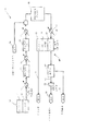
図1を参照すると、例示的な実施形態に係る後処理システムが示されている。該プロセスは、必要な熱をカソード入口流に供給した後に過剰水素が副産物として分離されるように、水素を回収するステップを含む。別の例示的な実施形態によれば、過剰水素は、補助燃料としてDFCアノードへと再循環される。 With reference to FIG. 1, a post-processing system according to an exemplary embodiment is shown. The process involves recovering hydrogen so that excess hydrogen is separated as a by-product after supplying the required heat to the cathode inlet stream. According to another exemplary embodiment, excess hydrogen is recirculated to the DFC anode as an auxiliary fuel.
燃料電池システム1は、カソード12(すなわち、第1のカソード)とアノード14(すなわち、第1のアノード)とを有する第1の燃料電池10を含む。例示的な一実施形態によれば、第1の燃料電池10は、DFCであり得る。アノード14は、少なくともCO2と水素とCOとを含むアノード排ガスを放出する。第1の熱交換器20は、DFCからアノード排ガスを受け取り、アノード排ガスを部分的に冷却する。第1の熱交換器20は、その後、第1の部分冷却ガスを放出する。第1の部分冷却ガスは、第1のシフト反応器21内の高温(「HT」)COシフト反応(例えば、水ーガスシフト反応)によって変換されて、第2の熱交換器22によって受け取られる第1のシフトガスが生成される。第1のシフト反応器21は、およそ310℃〜450℃の第1の温度で動作するように構成される。第1のシフト反応器21は、第1のシフトガスが第1の部分冷却ガスより高濃度のCO2と水素とを有するように、COと水をCO2と水素に変換するように構成され得る。第2の熱交換器22は、第1のシフトガスを部分的に冷却し、第2の部分冷却ガスを放出する。第2の部分冷却ガスは、第2のシフト反応器23内の低温(「LT」)COシフト反応によって変換されて、第3の熱交換器24によって受け取られる第2のシフトガスが生成される。第2のシフト反応器23は、第1の温度が第2の温度より高くなるように、およそ200℃〜250℃の第2の温度で動作するように構成される。第2のシフト反応器23は、第2のシフトガスが第2の部分冷却ガスより高濃度のCO2と水素とを有するように、COと水をCO2と水素に変換するように構成され得る。第3の熱交換器24は、第2のシフトガスを所望の温度まで冷却して、冷却ガスを放出する。例示的な一実施形態によれば、冷却ガスの温度は、第3の熱交換器24の下流側にある酸化装置30によって受け入れ可能な温度範囲に基づいている。
The
冷却ガスは、酸素ではなく、空気源26(すなわち、第1の空気源、制御空気源など)によって供給される(すなわち、注入される)空気と混合されて、混合ガスが生成される。例示的な一実施形態によれば、空気源26は、冷却ガスを構成するCO2、水素、水、および/またはCOのいずれか1つに対する空気の好適な比率を確立するように制御され得る。この好適な比率は、酸化装置の要件に基づき得る。混合ガスは、その後、COをCO2に変換するために、選択的酸化反応を実行するように構成された酸化装置30に供給される。選択的酸化は、COを除去するための化学プロセスである。このプロセスは、低温シフト反応器(例えば、第2のシフト反応器23と同様のシフト反応器)を使用した後に、貴金属触媒(例えば、白金、パラジウムーコバルト、パラジウムー銅、金など)の存在下で酸素を使用してCOを酸化するために段階的な選択的酸化装置を使用する。酸化装置30は、隔離のためのCO2を含む酸化ガスを放出し、反応により熱を発生させる。第4の熱交換器32は、酸化装置30から酸化ガスを受け取り、酸化ガスを冷却して少なくとも部分的にアノード入口流34を生成する。例示的な一実施形態によれば、酸化装置30は、CO2を含む酸化ガスから分離した排気を生成する。酸化装置30からの排気は放出される酸化ガス部分を構成しないので、酸化装置のために空気が使用され得、空気分離ユニットおよび/または水注入(例えば、酸化装置の温度制御のため)の必要がなくなる。
The cooling gas is not oxygen but is mixed with air supplied (ie, injected) by the air source 26 (ie, first air source, control air source, etc.) to produce a mixed gas. According to one exemplary embodiment, the
図1に示されているように、システム1はさらに、EHS40(第2の燃料電池とも呼ばれる)を含む。EHS40は、カソード42(すなわち、第2のカソード)、アノード44(すなわち、第2のアノード)、およびカソード42とアノード44との間に配置されたプロトン交換膜(「PEM」)46を含む。アノード44は、第4の熱交換器32から冷却アノード入口流34を受け取る。アノード44において、アノード入口流34中に存在する水素の少なくとも一部が、正電荷を持つ水素イオン(H+)になるように選択的に酸化され、その後、これがPEM46を通ってカソード42へと移動される。例示的な一実施形態によれば、酸化装置30、空気源26、および熱交換器32は、PEMとして150℃を超えて動作する高温膜(「HTM」)(例えば、PBIまたは固体酸膜)を組み込むことによって、図1に示すシステム1から除外され得る。さらに図1を参照すると、カソード42では、酸化剤が存在しないことにより、H+は気体水素に還元される。したがって、EHS40は、アノード入口流34から選択的に水素流50を生成し、放出する。水素流50は、副産物として生成され、システム1内で使用され得るか、または排出され得る。例示的な一実施形態によれば、シフト反応器21、23の各々は、対応する高温シフト反応器および低温シフト反応器内での水素回収を最大化して、EHS触媒の一酸化炭素中毒を防止するように構成される。別の例示的な実施形態によれば、水素流50は、比較的小さいエネルギー入力によって(電気化学的に)圧縮され得る。有利には、PEM46を介する移動は、最小エネルギー入力を利用し、可動部品は全く必要でない。例示的な一実施形態によれば、EHS40は、第1の燃料電池10からのアノード排ガスから、およそ95%の水素を回収し得る。
As shown in FIG. 1, the
EHS40のアノード44は、第2のアノード排ガスを生成する。第2のアノード排ガスは、凝縮器60に供給され得、凝縮器60は、第2のアノード排ガスをCO2流61と水流(すなわち、凝縮水)66とに分離する。凝縮器60からのCO2流61は、その後、CO2流61の少なくとも一部を液化するためにCO2圧縮機62を通り、隔離および/または使用場所(例えば、食品加工用)への排出(すなわち、輸送)に適した高濃度のCO2供給64を生成する。例示的な一実施形態によれば、凝縮器60内の水を水流66へと移した後、CO2流61は、およそ89%のCO2とおよそ9%の水とを含む。
The anode 44 of the
図2に示されているように、別の例示的な実施形態によれば、水素流50の少なくとも一部は、空気を使用して酸化され、熱を発生させ得る。EHS40のカソード42によって生成された水素流50の第1の部分51は、酸化装置52(すなわち、第2の酸化装置)に供給され、空気源54(すなわち、第2の空気源)からの空気によって酸化される。酸化は、少なくとも熱と水とを含む酸化水素流53を生成し、第5の熱交換器56を通して供給される。第5の熱交換器56は、酸化水素流53からの熱を移送して、第1の燃料電池10の第1のカソード12によって受け取られるカソード入口流36(例えば、石炭燃料発電所からの脱硫GHG)を予熱する。別の例示的な実施形態によれば、酸化水素流53は、EHS40のカソード42または任意の他のカソードによって受け取られるカソード入口流を予熱するのに使用され得る。酸化水素流53は、その後、システム1から排出され得る。
As shown in FIG. 2, according to another exemplary embodiment, at least a portion of the
図2に示されている実施形態では、カソード入口流36を加熱するのに使用される水素流50の第1の部分51は、カソード42によって生成された水素のおよそ45%を含む。残りの第2の部分55(例えば、水素流50のおよそ55%)は、副産物として生成され、システム1内で使用され得るか、または排出され得る。各々の部分51、55を形成する水素流50の割合は、他の例示的な実施形態に応じて異なり得る。例示的な一実施形態によれば、水素流50の第1の部分51は、カソード入口流36の所望レベルの予熱を行うのに必要な量に限定され得る。別の例示的な実施形態によれば、水素流50の第2の部分55(例えば、カソード入口流36を予熱するために第2の酸化装置52に供給されない水素)は、第1の燃料電池10の第1のアノード14に再循環(例えば、供給)され得、その結果、第1の燃料電池10を作動させるのに必要な天然ガス燃料投入量を低減することができる。
In the embodiment shown in FIG. 2, the
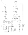
図3を参照すると、別の例示的な実施形態に係る後処理システムが示されている。このシステムにおいて、先の例示的な実施形態と同様に、アノード排ガス中に存在する水素が分離されて回収される。 With reference to FIG. 3, a post-processing system according to another exemplary embodiment is shown. In this system, the hydrogen present in the anode exhaust gas is separated and recovered, as in the previous exemplary embodiment.
燃料電池システム100は、カソード112とアノード114とを有する燃料電池110を含む。例示的な一実施形態によれば、燃料電池110は、第1の燃料電池10と実質的に同じDFCであり得る。アノード114は、少なくともCO2と水素とCOとを含むアノード排ガスを放出する。第1の熱交換器120は、DFCからアノード排ガスを受け取り、アノード排ガスを部分的に冷却する。第1の熱交換器120は、その後、第1の部分冷却ガスを放出する。第1の部分冷却ガスは、第1のシフト反応器121内の高温COシフト反応によって変換されて、第2の熱交換器122によって受け取られる第1のシフトガスが生成される。第1のシフト反応器121は、およそ310℃〜450℃の第1の温度で動作するように構成される。第1のシフト反応器121は、第1のシフトガスが第1の部分冷却ガスより高濃度のCO2と水素とを有するように、COと水をCO2と水素に変換するように構成され得る。第2の熱交換器122は、第1のシフトガスを部分的に冷却し、第2の部分冷却ガスを放出する。第2の部分冷却ガスは、第2のシフト反応器123内の低温COシフト反応によって変換されて、凝縮器160によって受け取られる第2のシフトガスが生成される。第2のシフト反応器123は、第1の温度が第2の温度より高くなるように、およそ200℃〜250℃の第2の温度で動作するように構成される。第2のシフト反応器123は、第2のシフトガスが第2の部分冷却ガスより高濃度のCO2と水素とを有するように、COと水をCO2と水素に変換するように構成され得る。凝縮器160は、第2のシフトガスを、少なくともCO2と水素とを含む乾燥(例えば、脱水)アノード排ガス流161と、分離した水流(すなわち、凝縮水)166とに分離する。例えば、乾燥アノード排ガス流161を形成する際に、水の実質的に全てがアノード排ガス流から除去される。凝縮器160からの乾燥アノード排ガス流161は、その後、圧縮機162に供給されて、圧縮アノード排ガス流を形成し、その後、圧縮アノード排ガス流をさらに冷却するために第3の熱交換器163に供給される。別の例示的な実施形態によれば、第3の熱交換器163は、圧縮機162の上流側(例えば、凝縮器160と圧縮機162との間)に配置され、乾燥アノード排ガス流161を冷却するように構成される。
The
システム100は、圧力スウィング吸着(「PSA」)ユニット170を含む。PSAユニット170は、第3の熱交換器163からの圧縮アノード排ガス流を受け取り、圧縮アノード排ガス流を水素流150とCO2流165とに分離するように構成される。PSAユニット170において、水素以外のガス(例えば、主としてCO2といくらかの水)は、高圧下で吸着床媒体によって吸着され、純粋な水素流150は、PSAユニット170で受け取られる圧縮アノード排ガス流の入口圧力に近い(例えば、実質的に同じ)圧力で、PSAユニット170から放出される。水素流150は、副産物として生成され、システム100内で使用され得るか、または排出され得る。PSAユニット170内の吸着床媒体は、最大吸着容量に達した後、CO2流165を生成する吸着ガスを除去するようにパージされる。このパージは、およそ20psiaの大気圧近くまで圧力を下げることによって行われる脱着によって生じる。CO2流165は、その後、CO2流165の少なくとも一部を液化するためにCO2圧縮機167に供給されて、隔離CO2供給164を生成する。
例示的な一実施形態によれば、システム100は、図2に示されている水素流50と同じ方法で、水素流150の一部を変換し得る。例えば、図4に示されているように、PSAユニット170によって生成された水素流150の第1の部分151は、酸化装置152に供給されて、空気源154からの空気によって酸化される。酸化は、少なくとも熱と水とを含む酸化水素流153を生成し、第4の熱交換器156を通して供給される。第4の熱交換器156は、酸化水素流153からの熱を移送して、第1の燃料電池110の第1のカソード112によって受け取られるカソード入口流136(例えば、石炭燃料発電所からの脱硫GHG)を予熱する。酸化水素流153は、その後、システム100から排出され得る。図2と同様に、水素流50の第1の部分151は、カソード入口流136の所望レベルの予熱を行うのに必要な量に限定され得る。別の例示的な実施形態によれば、水素流150の残りの第2の部分155(例えば、カソード入口流136を予熱するために酸化装置152に供給されない水素)は、燃料電池110のアノード114に再循環(例えば、供給)され得、その結果、燃料電池110を作動させるのに必要な天然ガス燃料投入量を低減することができる。
According to one exemplary embodiment, the
システム1およびシステム100のいずれに関しても、別の例示的な実施形態によれば、CO2を隔離するプロセスは、酸化装置内で全ての水素および他の可燃性物質を消費するステップと、カソード入口流を予熱するためにエネルギー容量を利用するステップとを含み得る。
For both
特定の実施形態では、燃料電池システムは、アノードとカソードとを有する燃料電池、酸化装置、および電気化学水素分離装置を含む。酸化装置は、アノードからのアノード排ガスと制御された空気源からの空気とを受け取り、アノード排ガスと空気とを選択的酸化反応で反応させるように構成される。分離装置は、酸化装置から酸化ガスを受け取り、残りのガスから分離した水素流とCO2流とを形成するように構成される。凝縮器は、酸化装置からCO2流を受け取り、CO2流を凝縮して水を分離し、CO2を液化するように構成される。 In certain embodiments, the fuel cell system includes a fuel cell having an anode and a cathode, an oxidizing device, and an electrochemical hydrogen separator. The oxidizing device is configured to receive the anode exhaust gas from the anode and the air from the controlled air source and react the anode exhaust gas with the air in a selective oxidation reaction. The separation device is configured to receive an oxidizing gas from the oxidizing device and form a hydrogen stream and a CO 2 stream separated from the remaining gas. Condenser receives the CO 2 stream from the oxidizer, to condense the CO 2 stream to separate the aqueous, configured to liquefy the CO 2.
他の実施形態では、燃料電池システムは、アノードとカソードとを有する燃料電池、凝縮器、および圧力スウィング吸着ユニットを含む。凝縮器は、アノードからアノード排ガスを受け取り、凝縮して、残りの凝縮ガスから水流を分離するように構成される。圧縮機は、残りの凝縮ガスを受け取って圧縮し、圧縮ガスを圧力スウィング吸着ユニットに供給する。圧力スウィング吸着ユニットは、水素流とCO2流とを分離する。CO2流は、CO2を液化するように構成された第2の圧縮機によって受け取られる。 In another embodiment, the fuel cell system includes a fuel cell having an anode and a cathode, a condenser, and a pressure swing adsorption unit. The condenser is configured to receive the anode exhaust gas from the anode, condense it, and separate the water stream from the remaining condensate. The compressor receives the remaining condensed gas, compresses it, and supplies the compressed gas to the pressure swing adsorption unit. The pressure swing adsorption unit separates the hydrogen stream and the CO 2 stream. The CO 2 stream is received by a second compressor configured to liquefy CO 2.
用語「およそ」、「約」、「実質的に」および同様の用語は、本明細書で使用される場合、本開示の主題に関連する当業者に一般的に認められた語法に即した広い意味を有するものとする。本開示を考察する当業者であれば、これらの用語は、記載され請求される特定の特徴を設定された正確な数値範囲に制限せずに説明できるように意図されていることを理解されたい。したがって、これらの用語は、記載され請求される主題の非実質的または重要でない修正または変更は、添付の請求項に記載されているように本発明の範囲内にあるものと見なされると解釈すべきである。 The terms "approximately," "about," "substantially," and similar terms, as used herein, are broad in line with those commonly accepted by those skilled in the art relating to the subject matter of this disclosure. It shall be meaningful. Those skilled in the art considering this disclosure should understand that these terms are intended to explain the particular features described and claimed without limitation to a set exact numerical range. .. Accordingly, these terms shall be construed as any non-substantial or non-substantial modification or modification of the subject matter described and claimed shall be deemed to be within the scope of the invention as set forth in the appended claims. Should be.
用語「結合される」、「接続される」などは、本明細書で使用される場合、2つの部材を互いに直接または間接的に接合することを意味する。このような接合は、固定式(例えば、永久的)または可動式(例えば、取り外し可能または解除可能)であり得る。このような接合は、2つの部材または2つの部材と任意の追加の中間部材とを互いに単一本体として一体形成することによって、または2つの部材または2つの部材と任意の追加の中間部材とが互いに取り付けられることによって実現され得る。 As used herein, the terms "joined", "connected" and the like mean joining two members directly or indirectly to each other. Such joints can be fixed (eg, permanent) or movable (eg, removable or removable). Such a joint is made by integrally forming two members or two members and any additional intermediate member with each other as a single body, or by combining the two members or two members with any additional intermediate member. It can be realized by being attached to each other.
本明細書において、要素の位置(例えば、「上部」、「底部」、「〜の上」、「〜の下」など)の参照は、図面内の様々な要素の配向を説明するためにのみ使用されている。様々な要素の配向は他の例示的な実施形態に応じて異なり得ること、およびこのような差異は本開示の範囲内にあることが意図されていることに留意されたい。 In the present specification, reference to the position of an element (eg, "top", "bottom", "above", "below", etc.) is only to illustrate the orientation of the various elements in the drawing. It is used. It should be noted that the orientation of the various elements may vary depending on other exemplary embodiments, and that such differences are intended to be within the scope of the present disclosure.
様々な例示的な実施形態の構造および配置は例示に過ぎないことに留意することが重要である。本開示では少しの実施形態しか詳細に説明されていないが、本開示を考察する当業者であれば、本明細書に記載されている主題の新奇な技術および利点から著しく逸脱せずに、多くの修正(例えば、サイズ、寸法、構造、様々な要素の形状および比率、パラメータ値、取付方法、材料の使用、色、配向などの変化)が可能であることを容易に理解するであろう。例えば、一体形成された要素として示されている要素は複数の部品または要素から構成され得、要素の位置は逆の位置またはそれ以外の異なる位置であり得、個々の要素もしくは位置の性質または数は変更され得る、または異なり得る。任意のプロセスもしくは方法ステップの順序またはシーケンスは、代替の実施形態に応じて異なり得る、または並べ替えられ得る。本発明の範囲から逸脱せずに、様々な実施形態の設計、動作条件、および設備において、他の置換、修正、変更および省略がなされてもよい。例えば、熱回収式熱交換器は、さらに最適化されてよい。 It is important to note that the structures and arrangements of the various exemplary embodiments are only exemplary. Although only a few embodiments have been described in detail in this disclosure, those skilled in the art considering this disclosure will not deviate significantly from the novel techniques and advantages of the subject matter described herein. It will be easily understood that modifications can be made (eg, changes in size, dimensions, structure, shapes and proportions of various elements, parameter values, mounting methods, material use, color, orientation, etc.). For example, an element shown as an integrally formed element can be composed of multiple parts or elements, the positions of the elements can be opposite positions or other different positions, and the nature or number of individual elements or positions. Can be changed or different. The sequence or sequence of any process or method step may vary or be rearranged depending on the alternative embodiment. Other substitutions, modifications, changes and omissions may be made in the design, operating conditions and equipment of various embodiments without departing from the scope of the present invention. For example, heat recovery heat exchangers may be further optimized.
[関連出願の相互参照]
本願は、2016年4月21日に出願された米国仮特許出願第62/325,711号の優先権を主張するものであり、これにより、この特許の内容全体を参照によって本願明細書に引用したものとする。
[Cross-reference of related applications]
This application claims the priority of US Provisional Patent Application No. 62 / 325,711 filed on April 21, 2016, whereby the entire contents of this patent are cited herein by reference. It is assumed that
Claims (14)
第1のアノードと第1のカソードとを備える第1の燃料電池であって、前記第1のアノードは第1のアノード排ガスを放出するように構成される、第1の燃料電池と、
前記第1のアノード排ガスと第1の空気源からの空気とを受け取り、前記第1のアノード排ガスと前記空気とを選択的酸化反応で反応させて、酸化ガスを放出するように構成された第1の酸化装置と、
電気化学水素分離装置として機能するように構成された第2の燃料電池であって、
前記第1の酸化装置から前記酸化ガスを受け取り、第2のアノード排ガスを放出するように構成された第2のアノード、および
水素流を放出するように構成された第2のカソード
を備える第2の燃料電池と、
前記第2のアノード排ガスを受け取り、水とCO2とを分離して放出するように構成された凝縮器と、
前記凝縮器から放出された前記CO 2 を受け取って液化するように構成された圧縮機と
を備える、燃料電池システム。 It ’s a fuel cell system,
A first fuel cell comprising a first anode and a first cathode, wherein the first anode is configured to emit the first anode exhaust gas.
The first anode exhaust gas and the air from the first air source are received, and the first anode exhaust gas and the air are reacted by a selective oxidation reaction to release the oxidation gas. Oxidizer of 1 and
A second fuel cell configured to function as an electrochemical hydrogen separator,
A second anode provided with a second anode configured to receive the oxidizing gas from the first oxidizing apparatus and emit a second anode exhaust gas, and a second cathode configured to emit a hydrogen stream. Fuel cell and
A condenser configured to receive the second anode exhaust gas and separate and release water and CO 2 .
A fuel cell system comprising a compressor configured to receive and liquefy the CO 2 emitted from the condenser.
前記第2のカソードからの前記水素流の第1の部分と第2の空気源からの空気とを受け取り、酸化水素流を放出するように構成された第2の酸化装置をさらに備える、燃料電池システム。 The fuel cell system according to claim 1.
A fuel cell further comprising a second oxidizing apparatus configured to receive the first portion of the hydrogen stream from the second cathode and the air from the second air source and release the hydrogen oxide stream. system.
前記酸化水素流から熱を受け取り、前記第1のカソードによって受け取られるカソード入口流に伝達するように構成された熱交換器をさらに備える、燃料電池システム。 The fuel cell system according to claim 2.
A fuel cell system further comprising a heat exchanger configured to receive heat from the hydrogen peroxide stream and transfer it to a cathode inlet stream received by the first cathode.
前記第1のアノードは、前記第2のカソードからの前記水素流の第2の部分を受け取るように構成される、燃料電池システム。 The fuel cell system according to claim 2.
A fuel cell system in which the first anode is configured to receive a second portion of the hydrogen stream from the second cathode.
前記第1のアノード排ガスを受け取って冷却して、第1の部分冷却ガスを放出するように構成された第1の熱交換器と、
前記第1の部分冷却ガスを受け取り、前記第1の部分冷却ガスに対して第1の温度で第1のCOシフト反応を実行し、第1のシフトガスを放出するように構成された第1のCOシフト反応器と、
前記第1のシフトガスを受け取って冷却して、第2の部分冷却ガスを放出するように構成された第2の熱交換器と、
前記第2の部分冷却ガスを受け取り、前記第2の部分冷却ガスに対して第2の温度で第2のCOシフト反応を実行し、第2のシフトガスを放出するように構成された第2のCOシフト反応器と、
前記第2のシフトガスを受け取って冷却して、冷却ガスを放出するように構成された第3の熱交換器と
をさらに備え、
前記第1の酸化装置で受け取られる前記第1のアノード排ガスは、前記第3の熱交換器から放出された冷却ガスであり、
前記第1の温度は、前記第2の温度より高い、燃料電池システム。 The fuel cell system according to claim 1.
A first heat exchanger configured to receive and cool the first anode exhaust gas and release the first partial cooling gas.
A first configured to receive the first partial cooling gas, perform a first CO shift reaction on the first partial cooling gas at a first temperature, and release the first shift gas. CO shift reactor and
A second heat exchanger configured to receive and cool the first shift gas and release a second partial cooling gas.
A second configured to receive the second partial cooling gas, perform a second CO shift reaction on the second partial cooling gas at a second temperature, and release the second shift gas. CO shift reactor and
Further comprising a third heat exchanger configured to receive and cool the second shift gas and release the cooling gas.
The first anode exhaust gas received by the first oxidizing apparatus is a cooling gas released from the third heat exchanger.
A fuel cell system in which the first temperature is higher than the second temperature.
前記第1の酸化装置において、前記第1のアノードからの前記第1のアノード排ガスと前記第1の空気源からの空気とを受け取るステップと、
前記第1の酸化装置から前記酸化ガスを放出するステップと、
前記第2の燃料電池において、前記第2のアノードで前記酸化ガスを受け取り、前記酸化ガス中の水素を電気化学的に分離し、前記第2のカソードから前記水素流を放出し、前記第2のアノードから前記第2のアノード排ガスを放出するステップと
を含む、方法。 A method for treating fuel cell exhaust in the fuel cell system according to claim 1.
In the first oxidizing apparatus, a step of receiving the first anode exhaust gas from the first anode and air from the first air source, and
The step of releasing the oxidizing gas from the first oxidizing device, and
In the second fuel cell, the oxidation gas is received at the second anode, hydrogen in the oxidation gas is electrochemically separated, and the hydrogen stream is released from the second cathode, and the second including from the anode and the step of releasing said second anode exhaust gas, methods.
前記凝縮器において、前記第2のアノード排ガスを受け取り、前記第2のアノード排ガス中の水とCO2とを分離するステップ
をさらに含む、方法。 The method according to claim 6 , wherein the method is
A method further comprising the step of receiving the second anode exhaust gas in the condenser and separating water and CO 2 in the second anode exhaust gas.
前記第2のアノードに前記酸化ガスを供給する前に、熱交換器内で前記酸化ガスを冷却するステップをさらに含む、方法。 The method according to claim 6 or 7 , wherein the method is
A method further comprising the step of cooling the oxidative gas in a heat exchanger before supplying the oxidative gas to the second anode.
前記第1の酸化装置において、前記第1のアノードからの前記第1のアノード排ガスと前記第1の空気源からの空気とを受け取るステップと、
前記第1の酸化装置から前記酸化ガスを放出するステップと、
前記第2の燃料電池において、前記第2のアノードで前記酸化ガスを受け取り、前記酸化ガス中の水素を電気化学的に分離し、前記第2のカソードから前記水素流を放出し、前記第2のアノードから前記第2のアノード排ガスを放出するステップと、
前記凝縮器において、前記第2のアノード排ガスを受け取り、前記第2のアノード排ガス中の水とCO2とを分離するステップと、
前記圧縮機において、前記凝縮器から前記CO2を受け取り、液化CO2を放出するステップと
を含む、方法。 The method for treating fuel cell exhaust in the fuel cell system according to claim 1, wherein the method is:
In the first oxidizing apparatus, a step of receiving the first anode exhaust gas from the first anode and air from the first air source, and
The step of releasing the oxidizing gas from the first oxidizing device, and
In the second fuel cell, the oxidation gas is received at the second anode, hydrogen in the oxidation gas is electrochemically separated, and the hydrogen stream is released from the second cathode, and the second The step of discharging the second anode exhaust gas from the anode of
A step of receiving the second anode exhaust gas in the condenser and separating water and CO 2 in the second anode exhaust gas.
A method comprising the step of receiving the CO 2 from the condenser and releasing the liquefied CO 2 in the compressor.
前記第2のアノードに前記酸化ガスを供給する前に、熱交換器内で前記酸化ガスを冷却するステップをさらに含む、方法。 The method according to claim 9.
A method further comprising the step of cooling the oxidative gas in a heat exchanger before supplying the oxidative gas to the second anode.
前記第1の酸化装置において、前記第1のアノードからの前記第1のアノード排ガスと前記第1の空気源からの空気とを受け取るステップと、
前記第1の酸化装置から前記酸化ガスを放出するステップと、
前記第2の燃料電池において、前記第2のアノードで前記酸化ガスを受け取り、前記酸化ガス中の水素を電気化学的に分離し、前記第2のカソードから前記水素流を放出し、前記第2のアノードから前記第2のアノード排ガスを放出するステップと、
前記第1の熱交換器において、前記第1のアノード排ガスを冷却して、前記第1の部分冷却ガスを放出するステップと、
前記第1のCOシフト反応器において、前記第1の部分冷却ガスに対して前記第1の温度で第1のCOシフト反応を実行し、前記第1のシフトガスを放出するステップと、
前記第2の熱交換器において、前記第1のシフトガスを冷却して、前記第2の部分冷却ガスを放出するステップと、
前記第2のCOシフト反応器において、前記第2の部分冷却ガスに対して前記第2の温度で第2のCOシフト反応を実行し、前記第2のシフトガスを放出するステップと、
前記第3の熱交換器において、前記第2のシフトガスを冷却して、前記冷却ガスを放出するステップと
をさらに含む、方法。 The method for treating fuel cell exhaust in the fuel cell system according to claim 5 , wherein the method is:
In the first oxidizing apparatus, a step of receiving the first anode exhaust gas from the first anode and air from the first air source, and
The step of releasing the oxidizing gas from the first oxidizing device, and
In the second fuel cell, the oxidation gas is received at the second anode, hydrogen in the oxidation gas is electrochemically separated, and the hydrogen stream is released from the second cathode, and the second The step of discharging the second anode exhaust gas from the anode of
In the first heat exchanger, the step of cooling the first anode exhaust gas and releasing the first partial cooling gas, and
In the first CO shift reactor, a step of executing the first CO shift reaction with respect to the first partial cooling gas at the first temperature and releasing the first shift gas.
In the second heat exchanger, the step of cooling the first shift gas and releasing the second partial cooling gas, and
In the second CO shift reactor, a step of executing a second CO shift reaction with respect to the second partial cooling gas at the second temperature and releasing the second shift gas, and a step of discharging the second shift gas.
A method further comprising, in the third heat exchanger, a step of cooling the second shift gas and releasing the cooling gas.
前記第2のアノードに前記酸化ガスを供給する前に、第4の熱交換器内で前記酸化ガスを冷却するステップをさらに含む、方法。 The method according to claim 11.
A method further comprising the step of cooling the oxidative gas in a fourth heat exchanger before supplying the oxidative gas to the second anode.
前記第1の酸化装置において、前記第1のアノードからの前記第1のアノード排ガスと前記第1の空気源からの空気とを受け取るステップと、
前記第1の酸化装置から前記酸化ガスを放出するステップと、
前記第2の燃料電池において、前記第2のアノードで前記酸化ガスを受け取り、前記酸化ガス中の水素を電気化学的に分離し、前記第2のカソードから前記水素流を放出し、前記第2のアノードから前記第2のアノード排ガスを放出するステップと、
前記第2の酸化装置において、前記水素流の前記第1の部分と前記第2の空気源からの空気とを受け取り、前記酸化水素流を放出するステップと、
前記酸化水素流からの熱を前記第1のカソードによって受け取られるカソード入口流に伝達するステップと
を含む、方法。 The method for treating fuel cell exhaust in the fuel cell system according to claim 2, wherein the method is:
In the first oxidizing apparatus, a step of receiving the first anode exhaust gas from the first anode and air from the first air source, and
The step of releasing the oxidizing gas from the first oxidizing device, and
In the second fuel cell, the oxidation gas is received at the second anode, hydrogen in the oxidation gas is electrochemically separated, and the hydrogen stream is released from the second cathode, and the second The step of discharging the second anode exhaust gas from the anode of
In the second oxidizing apparatus, a step of receiving the first portion of the hydrogen stream and air from the second air source and releasing the hydrogen peroxide stream.
A method comprising transferring heat from the hydrogen peroxide stream to a cathode inlet stream received by the first cathode.
前記第2のアノードに前記酸化ガスを供給する前に、熱交換器内で前記酸化ガスを冷却するステップをさらに含む、方法。 The method according to claim 13.
A method further comprising the step of cooling the oxidative gas in a heat exchanger before supplying the oxidative gas to the second anode.
Priority Applications (2)
| Application Number | Priority Date | Filing Date | Title |
|---|---|---|---|
| JP2021043584A JP7270916B2 (en) | 2016-04-21 | 2021-03-17 | Post-treatment of molten carbonate fuel cell anode exhaust for carbon dioxide capture |
| JP2023011141A JP2023055803A (en) | 2016-04-21 | 2023-01-27 | Molten carbonate fuel cell anode exhaust post-processing for carbon dioxide capture |
Applications Claiming Priority (3)
| Application Number | Priority Date | Filing Date | Title |
|---|---|---|---|
| US201662325711P | 2016-04-21 | 2016-04-21 | |
| US62/325,711 | 2016-04-21 | ||
| PCT/US2017/028594 WO2017184848A1 (en) | 2016-04-21 | 2017-04-20 | Molten carbonate fuel cell anode exhaust post-processing for carbon dioxide capture |
Related Child Applications (1)
| Application Number | Title | Priority Date | Filing Date |
|---|---|---|---|
| JP2021043584A Division JP7270916B2 (en) | 2016-04-21 | 2021-03-17 | Post-treatment of molten carbonate fuel cell anode exhaust for carbon dioxide capture |
Publications (2)
| Publication Number | Publication Date |
|---|---|
| JP2019518304A JP2019518304A (en) | 2019-06-27 |
| JP6857433B2 true JP6857433B2 (en) | 2021-04-14 |
Family
ID=60116491
Family Applications (3)
| Application Number | Title | Priority Date | Filing Date |
|---|---|---|---|
| JP2018555215A Active JP6857433B2 (en) | 2016-04-21 | 2017-04-20 | Post-treatment of molten carbonate fuel cell anode exhaust for carbon dioxide capture |
| JP2021043584A Active JP7270916B2 (en) | 2016-04-21 | 2021-03-17 | Post-treatment of molten carbonate fuel cell anode exhaust for carbon dioxide capture |
| JP2023011141A Pending JP2023055803A (en) | 2016-04-21 | 2023-01-27 | Molten carbonate fuel cell anode exhaust post-processing for carbon dioxide capture |
Family Applications After (2)
| Application Number | Title | Priority Date | Filing Date |
|---|---|---|---|
| JP2021043584A Active JP7270916B2 (en) | 2016-04-21 | 2021-03-17 | Post-treatment of molten carbonate fuel cell anode exhaust for carbon dioxide capture |
| JP2023011141A Pending JP2023055803A (en) | 2016-04-21 | 2023-01-27 | Molten carbonate fuel cell anode exhaust post-processing for carbon dioxide capture |
Country Status (7)
| Country | Link |
|---|---|
| US (2) | US11211625B2 (en) |
| EP (2) | EP3446349B1 (en) |
| JP (3) | JP6857433B2 (en) |
| KR (2) | KR102326948B1 (en) |
| CN (1) | CN109314257B (en) |
| CA (2) | CA3021637C (en) |
| WO (1) | WO2017184848A1 (en) |
Families Citing this family (5)
| Publication number | Priority date | Publication date | Assignee | Title |
|---|---|---|---|---|
| US10566639B2 (en) * | 2016-04-27 | 2020-02-18 | Fuelcell Energy, Inc. | Carbon dioxide sequestration using molten carbonate fuel cell and hydrogen separation technology |
| US10797332B2 (en) * | 2018-08-31 | 2020-10-06 | Fuelcell Energy, Inc. | Low pressure carbon dioxide removal from the anode exhaust of a fuel cell |
| CN109921073B (en) * | 2019-03-14 | 2023-11-03 | 西南化工研究设计院有限公司 | Method and system for efficiently preparing hydrogen for hydrogen fuel cell by anode gas of fuel cell |
| GB2594893B (en) * | 2019-03-21 | 2022-05-18 | Intelligent Energy Ltd | Evaporatively cooled fuel cell systems with cathode exhaust turbine boost |
| JP2023119894A (en) * | 2022-02-17 | 2023-08-29 | 株式会社 商船三井 | fuel cell power generation system |
Family Cites Families (163)
| Publication number | Priority date | Publication date | Assignee | Title |
|---|---|---|---|---|
| US4476633A (en) * | 1981-12-30 | 1984-10-16 | Heinz Brych | Pliers for punching cards or tickets |
| US4449994A (en) | 1982-01-15 | 1984-05-22 | Air Products And Chemicals, Inc. | Low energy process for separating carbon dioxide and acid gases from a carbonaceous off-gas |
| US4476683A (en) * | 1982-12-20 | 1984-10-16 | General Electric Company | Energy efficient multi-stage water gas shift reaction |
| US4532192A (en) * | 1984-11-06 | 1985-07-30 | Energy Research Corporation | Fuel cell system |
| JPS62241524A (en) | 1986-04-14 | 1987-10-22 | Kawasaki Steel Corp | Separation and purification for carbon monoxide excellent in stabilization of purity |
| US4743517A (en) | 1987-08-27 | 1988-05-10 | International Fuel Cells Corporation | Fuel cell power plant with increased reactant pressures |
| JPH07123050B2 (en) | 1989-04-21 | 1995-12-25 | 株式会社日立製作所 | Molten carbonate fuel cell power plant |
| JPH04334870A (en) | 1991-05-13 | 1992-11-20 | Mitsubishi Electric Corp | Fused carbonate type fuel cell generating set |
| US5518828A (en) | 1994-07-21 | 1996-05-21 | Bechtel Group, Inc. | Thermal integration of an air-cooled fuel cell stack |
| US6162556A (en) | 1995-12-04 | 2000-12-19 | Siemens Aktiengesellschaft | Method for operating a high-temperature fuel cell installation, and a high-temperature fuel cell installation |
| US6063515A (en) | 1997-12-22 | 2000-05-16 | Ballard Power Systems Inc. | Integrated fuel cell electric power generation system for submarine applications |
| JPH11312527A (en) * | 1998-04-28 | 1999-11-09 | Nippon Steel Corp | Molten carbonate type fuel cell power generation-exhaust gas recovery combined system using by-product gas in production of iron |
| JP3644667B2 (en) | 1999-07-06 | 2005-05-11 | 三菱電機株式会社 | Fuel cell power generator |
| US6280865B1 (en) | 1999-09-24 | 2001-08-28 | Plug Power Inc. | Fuel cell system with hydrogen purification subsystem |
| US6835481B2 (en) | 2000-03-29 | 2004-12-28 | Idatech, Llc | Fuel cell system with load management |
| US6921595B2 (en) | 2000-05-31 | 2005-07-26 | Nuvera Fuel Cells, Inc. | Joint-cycle high-efficiency fuel cell system with power generating turbine |
| US7601207B2 (en) | 2000-09-28 | 2009-10-13 | Proton Energy Systems, Inc. | Gas recovery system |
| US6887601B2 (en) | 2000-09-28 | 2005-05-03 | Proton Energy Systems, Inc. | Regenerative electrochemical cell system and method for use thereof |
| JP2004512650A (en) | 2000-10-27 | 2004-04-22 | クエストエアー テクノロジーズ インコーポレイテッド | System and method for supplying hydrogen to a fuel cell |
| US7097925B2 (en) * | 2000-10-30 | 2006-08-29 | Questair Technologies Inc. | High temperature fuel cell power plant |
| US20020142198A1 (en) | 2000-12-08 | 2002-10-03 | Towler Gavin P. | Process for air enrichment in producing hydrogen for use with fuel cells |
| AU2002215752A1 (en) | 2000-12-08 | 2002-06-18 | Denis Connor | Methods and apparatuses for gas separation by pressure swing adsorption with partial gas product feed to fuel cell power source |
| US6517963B2 (en) | 2000-12-13 | 2003-02-11 | Plug Power Inc. | Carbon monoxide filter |
| US7014940B2 (en) | 2001-03-26 | 2006-03-21 | Matsushita Electric Industrial Co., Ltd. | High-polymer electrolyte fuel cell |
| JP2002334714A (en) | 2001-05-09 | 2002-11-22 | Tokyo Gas Co Ltd | Hydrogen manufacturing system incorporating fuel cell |
| US6660069B2 (en) | 2001-07-23 | 2003-12-09 | Toyota Jidosha Kabushiki Kaisha | Hydrogen extraction unit |
| EP1306916B1 (en) | 2001-10-23 | 2016-09-28 | NuCellSys GmbH | Fuel cell system and method for operating the same |
| US6833207B2 (en) | 2001-11-09 | 2004-12-21 | Hydrogenics Corporation | Unitized regenerative fuel cell with bifunctional fuel cell humidifier and water electrolyzer |
| JP3972675B2 (en) | 2002-02-15 | 2007-09-05 | 日産自動車株式会社 | Fuel cell system |
| US20030207161A1 (en) | 2002-05-01 | 2003-11-06 | Ali Rusta-Sallehy | Hydrogen production and water recovery system for a fuel cell |
| US7141323B2 (en) | 2002-08-07 | 2006-11-28 | Plug Power Inc. | Method and apparatus for electrochemical compression and expansion of hydrogen in a fuel cell system |
| US7045233B2 (en) | 2002-08-07 | 2006-05-16 | Plug Power Inc. | Method and apparatus for electrochemical compression and expansion of hydrogen in a fuel cell system |
| US7132182B2 (en) | 2002-08-07 | 2006-11-07 | Plug Power Inc. | Method and apparatus for electrochemical compression and expansion of hydrogen in a fuel cell system |
| US6821664B2 (en) | 2002-09-20 | 2004-11-23 | Plug Power, Inc. | Method and apparatus for a combined fuel cell and hydrogen purification system |
| US7011903B2 (en) | 2002-09-20 | 2006-03-14 | Plug Power Inc. | Method and apparatus for a combined fuel cell and hydrogen purification system |
| US7285350B2 (en) | 2002-09-27 | 2007-10-23 | Questair Technologies Inc. | Enhanced solid oxide fuel cell systems |
| JP2004171802A (en) | 2002-11-18 | 2004-06-17 | Osaka Gas Co Ltd | Fuel cell system |
| NO320939B1 (en) * | 2002-12-10 | 2006-02-13 | Aker Kvaerner Engineering & Te | Process for exhaust gas treatment in fuel cell system based on solid oxides |
| US20040146760A1 (en) | 2003-01-21 | 2004-07-29 | Honda Motor Co., Ltd. | Hydrogen supply unit |
| US6994929B2 (en) | 2003-01-22 | 2006-02-07 | Proton Energy Systems, Inc. | Electrochemical hydrogen compressor for electrochemical cell system and method for controlling |
| US7087333B2 (en) | 2003-02-26 | 2006-08-08 | General Motors Corporation | Hydrogen recirculation without a pump |
| US20040197612A1 (en) | 2003-02-26 | 2004-10-07 | Questair Technologies Inc. | Hydrogen recycle for high temperature fuel cells |
| US7276306B2 (en) | 2003-03-12 | 2007-10-02 | The Regents Of The University Of California | System for the co-production of electricity and hydrogen |
| US6924053B2 (en) | 2003-03-24 | 2005-08-02 | Ion America Corporation | Solid oxide regenerative fuel cell with selective anode tail gas circulation |
| DE10313438A1 (en) | 2003-03-26 | 2004-11-04 | Uhde Gmbh | Process for the selective removal of hydrogen sulfide and CO2 from raw gas |
| US7482078B2 (en) | 2003-04-09 | 2009-01-27 | Bloom Energy Corporation | Co-production of hydrogen and electricity in a high temperature electrochemical system |
| JP4274846B2 (en) | 2003-04-30 | 2009-06-10 | 三菱重工業株式会社 | Carbon dioxide recovery method and system |
| US7060382B2 (en) | 2003-05-15 | 2006-06-13 | Fuelcell Energy, Inc. | Fuel cell system with recycle of anode exhaust gas |
| US20050003247A1 (en) | 2003-07-01 | 2005-01-06 | Ai-Quoc Pham | Co-production of hydrogen and electricity using pyrolysis and fuel cells |
| US7252900B2 (en) | 2003-09-09 | 2007-08-07 | Plug Power Inc. | Combination fuel cell and ion pump, and methods and infrastructure systems employing same |
| US7245406B2 (en) | 2003-09-17 | 2007-07-17 | Dai Nippon Printing Co., Ltd. | Method for forming fine concavo-convex patterns, method for producing optical diffraction structure, and method for copying optical diffraction structure |
| US20050098034A1 (en) | 2003-11-12 | 2005-05-12 | Gittleman Craig S. | Hydrogen purification process using pressure swing adsorption for fuel cell applications |
| US20050123810A1 (en) | 2003-12-09 | 2005-06-09 | Chellappa Balan | System and method for co-production of hydrogen and electrical energy |
| JP2005179083A (en) | 2003-12-16 | 2005-07-07 | Nippon Oil Corp | Hydrogen producing apparatus, fuel cell system, and its operatin method |
| AU2003288778A1 (en) | 2003-12-30 | 2005-07-21 | Lg Electronics Inc. | Fuel cell system and control method thereof |
| WO2005069416A1 (en) | 2004-01-14 | 2005-07-28 | Toyota Jidosha Kabushiki Kaisha | Fuel cell system and power generation method thereof |
| US7422810B2 (en) * | 2004-01-22 | 2008-09-09 | Bloom Energy Corporation | High temperature fuel cell system and method of operating same |
| DE102004006915B4 (en) * | 2004-02-12 | 2005-11-24 | Mayer, Günter, Dipl.-Ing. | Fuel cell and method for depletion of carbon dioxide |
| US7752848B2 (en) | 2004-03-29 | 2010-07-13 | General Electric Company | System and method for co-production of hydrogen and electrical energy |
| JP2005302422A (en) | 2004-04-08 | 2005-10-27 | Nissan Motor Co Ltd | Fuel cell system |
| US20050233188A1 (en) | 2004-04-16 | 2005-10-20 | Yoshihiko Kurashima | Fuel cell operation method |
| US7255949B2 (en) | 2004-05-25 | 2007-08-14 | Protonetics International, Inc. | Systems and methods to generate hydrogen and electrical power in a reversible compound fuel cell |
| US7396603B2 (en) | 2004-06-03 | 2008-07-08 | Fuelcell Energy, Inc. | Integrated high efficiency fossil fuel power plant/fuel cell system with CO2 emissions abatement |
| FI120476B (en) | 2004-10-28 | 2009-10-30 | Waertsilae Finland Oy | Flow arrangement of fuel cell stacks |
| US7399342B2 (en) | 2004-12-22 | 2008-07-15 | Idatech, Llc | Systems and methods for regulating heating assembly operation through pressure swing adsorption purge control |
| KR20070097050A (en) | 2004-12-28 | 2007-10-02 | 가부시키가이샤 지에스 유아사 코포레이션 | Stand-alone hydrogen production system |
| EP1843424A1 (en) | 2004-12-28 | 2007-10-10 | GS Yuasa Corporation | Fuel cell power generating device |
| US20060188761A1 (en) | 2005-01-25 | 2006-08-24 | O'brien Christopher J | Fuel cell power plants |
| US20060228593A1 (en) | 2005-04-06 | 2006-10-12 | Grieve Malcolm J | PEM-SOFC hybrid power generation systems |
| FR2884305A1 (en) | 2005-04-08 | 2006-10-13 | Air Liquide | Carbon dioxide separating method for iron and steel industry, involves receiving flow enriched in carbon dioxide from absorption unit, sending it towards homogenization unit and subjecting carbon dioxide to intermediate compression stage |
| JP4916138B2 (en) | 2005-07-08 | 2012-04-11 | 中国電力株式会社 | Power generation system |
| US7520916B2 (en) | 2005-07-25 | 2009-04-21 | Bloom Energy Corporation | Partial pressure swing adsorption system for providing hydrogen to a vehicle fuel cell |
| US7591880B2 (en) | 2005-07-25 | 2009-09-22 | Bloom Energy Corporation | Fuel cell anode exhaust fuel recovery by adsorption |
| JP5542332B2 (en) | 2005-07-25 | 2014-07-09 | ブルーム エナジー コーポレーション | Fuel cell system that partially recycles anode exhaust |
| DK1908144T3 (en) | 2005-07-25 | 2012-08-13 | Bloom Energy Corp | FUEL CELL SYSTEM WITH ELECTROCHEMICAL ANODE EXHAUST GAS RECYCLING |
| JP5011673B2 (en) | 2005-08-08 | 2012-08-29 | 株式会社日立製作所 | Fuel cell power generation system |
| US20070044657A1 (en) | 2005-09-01 | 2007-03-01 | Laven Arne | Fuel cell systems and methods for passively increasing hydrogen recovery through vacuum-assisted pressure swing adsorption |
| US8097374B2 (en) | 2005-11-16 | 2012-01-17 | Bloom Energy Corporation | System and method for providing reformed fuel to cascaded fuel cell stacks |
| US20100104903A1 (en) | 2005-12-23 | 2010-04-29 | Mallika Gummalla | Power Plant With Membrane Water Gas Shift Reactor System |
| WO2007090072A2 (en) | 2006-01-30 | 2007-08-09 | H2 Pump Llc | Apparatus and methods for electrochemical hydrogen manipulation |
| JP4542046B2 (en) | 2006-01-30 | 2010-09-08 | セイコープレシジョン株式会社 | Drilling method and drilling device |
| WO2007106139A2 (en) | 2006-03-10 | 2007-09-20 | Intelligent Energy, Inc. | Hydrogen purification process and system |
| WO2007117406A2 (en) | 2006-04-03 | 2007-10-18 | Bloom Energy Corporation | Fuel cell system and balance of plant configuration |
| US20070246374A1 (en) | 2006-04-20 | 2007-10-25 | H2 Pump Llc | Performance management for integrated hydrogen separation and compression systems |
| US20070246363A1 (en) | 2006-04-20 | 2007-10-25 | H2 Pump Llc | Integrated electrochemical hydrogen compression systems |
| US8158290B2 (en) | 2006-04-21 | 2012-04-17 | Plug Power, Inc. | Recovering a reactant from a fuel cell exhaust flow |
| JP2007292010A (en) | 2006-04-27 | 2007-11-08 | Toyota Motor Corp | Purification of exhaust gas exhausted from internal combustion engine and including nitrogen oxides |
| US7862938B2 (en) * | 2007-02-05 | 2011-01-04 | Fuelcell Energy, Inc. | Integrated fuel cell and heat engine hybrid system for high efficiency power generation |
| US20090068512A1 (en) | 2007-03-08 | 2009-03-12 | Alexander Gofer | Hydrogen refueling station |
| US7883803B2 (en) | 2007-03-30 | 2011-02-08 | Bloom Energy Corporation | SOFC system producing reduced atmospheric carbon dioxide using a molten carbonated carbon dioxide pump |
| US7833668B2 (en) * | 2007-03-30 | 2010-11-16 | Bloom Energy Corporation | Fuel cell system with greater than 95% fuel utilization |
| CN101285004B (en) | 2007-04-11 | 2010-12-15 | 中国科学院工程热物理研究所 | Multifunctional energy resource system |
| US20080292921A1 (en) | 2007-05-22 | 2008-11-27 | Balasubramanian Lakshmanan | Recovery of inert gas from a fuel cell exhaust stream |
| WO2008150524A2 (en) | 2007-06-04 | 2008-12-11 | Bloom Energy Corporation | Structure for high temperature fuel cell system start up and shutdown |
| EA201000124A1 (en) | 2007-07-25 | 2010-08-30 | Бп Олтернетив Энерджи Интернэшнл Лимитед | SEPARATION OF CARBON AND HYDROGEN DIOXIDE |
| EP2186155B1 (en) | 2007-08-08 | 2011-10-19 | Saint-Gobain Ceramics & Plastics, Inc. | Anode exhaust recycle system with membrane hydrogen separator |
| JP5270903B2 (en) | 2007-10-31 | 2013-08-21 | Jfeスチール株式会社 | Blast furnace gas calorie increase method |
| DE112007003752A5 (en) * | 2007-11-10 | 2010-10-07 | Vollmar, Horst-Eckart, Dr.-Ing. | High-temperature fuel cell system with partial circulation of the anode exhaust gas and discharge of gas components |
| US8293412B2 (en) | 2007-11-20 | 2012-10-23 | Bloom Energy Corporation | Enhanced efficiency of a combined SORFC energy storage and fuel generation system |
| EP2220713A1 (en) | 2007-12-17 | 2010-08-25 | Shell Internationale Research Maatschappij B.V. | Fuel cell-based process for generating electrical power |
| EP2223371A1 (en) | 2007-12-17 | 2010-09-01 | Shell Internationale Research Maatschappij B.V. | Fuel cell-based process for generating electrical power |
| US20090155650A1 (en) | 2007-12-17 | 2009-06-18 | Jingyu Cui | System and process for generating electrical power |
| EP2220714A1 (en) | 2007-12-17 | 2010-08-25 | Shell Internationale Research Maatschappij B.V. | Fuel cell-based process for generating electrical power |
| EP2235777A1 (en) | 2007-12-28 | 2010-10-06 | Saint-Gobain Ceramics & Plastics, Inc. | Fuel cell system |
| US8062799B2 (en) * | 2008-08-19 | 2011-11-22 | Fuelcell Energy, Inc. | High-efficiency dual-stack molten carbonate fuel cell system |
| JP2010055927A (en) | 2008-08-28 | 2010-03-11 | Toyota Motor Corp | Fuel cell system |
| US8343241B2 (en) | 2009-02-11 | 2013-01-01 | Natural Energy Systems Inc. | Process for the conversion of organic material to methane rich fuel gas |
| RU2011140704A (en) | 2009-03-09 | 2013-04-20 | Бп Олтернетив Энерджи Интернэшнл Лимитед | SEPARATION OF CARBON DIOXIDE AND HYDROGEN |
| JP5106461B2 (en) | 2009-03-27 | 2012-12-26 | 中国電力株式会社 | Carbon dioxide recovery device |
| US20100243475A1 (en) | 2009-03-27 | 2010-09-30 | H2 Pump Llc | Electrochemical Hydrogen Reclamation System |
| US20100266923A1 (en) | 2009-04-15 | 2010-10-21 | Bloom Energy Corporation | Fuel cell system with electrochemical hydrogen pump and method of operating same |
| US8500868B2 (en) | 2009-05-01 | 2013-08-06 | Massachusetts Institute Of Technology | Systems and methods for the separation of carbon dioxide and water |
| US20120167620A1 (en) | 2009-05-15 | 2012-07-05 | Eva Marfilia Van Dorst | Method and system for separating co2 from synthesis gas or flue gas |
| DE102009031774B4 (en) | 2009-06-30 | 2012-02-02 | Fraunhofer-Gesellschaft zur Förderung der angewandten Forschung e.V. | High-temperature fuel cell system |
| IT1394740B1 (en) * | 2009-07-14 | 2012-07-13 | Ansaldo Fuel Cells Spa | APPARATUS AND METHOD FOR THERMAL MANAGEMENT OF MCFC PILE |
| US8241400B2 (en) | 2009-07-15 | 2012-08-14 | L'air Liquide Societe Anonyme Pour L'etude Et L'exploitation Des Procedes Georges Claude | Process for the production of carbon dioxide utilizing a co-purge pressure swing adsorption unit |
| WO2011006625A1 (en) | 2009-07-16 | 2011-01-20 | Basf Se | Method for operating a fuel cell, and a corresponding fuel cell |
| US8790618B2 (en) | 2009-12-17 | 2014-07-29 | Dcns Sa | Systems and methods for initiating operation of pressure swing adsorption systems and hydrogen-producing fuel processing systems incorporating the same |
| US20130014484A1 (en) | 2009-12-21 | 2013-01-17 | Luciano Caprile | System and method for separating co2 from combustion exhaust gas by means of mcfc multistacks |
| JP2011141967A (en) | 2010-01-05 | 2011-07-21 | Chugoku Electric Power Co Inc:The | Power generation system |
| WO2011089382A2 (en) | 2010-01-21 | 2011-07-28 | Bp Alternative Energy International Limited | Purification of a co2-rich stream |
| JP2011181440A (en) | 2010-03-03 | 2011-09-15 | Panasonic Corp | Fuel cell system |
| JP5698540B2 (en) | 2010-03-08 | 2015-04-08 | エア・ウォーター株式会社 | Syngas production method and apparatus |
| KR101658674B1 (en) | 2010-07-02 | 2016-09-21 | 엘지전자 주식회사 | Ice storing apparatus and control method therof |
| US9685665B2 (en) | 2010-08-16 | 2017-06-20 | Doosan Fuel Cell America, Inc. | System and method for thermal priority operation of a fuel cell power plant |
| US8388918B2 (en) | 2010-09-08 | 2013-03-05 | Bert Zauderer | Physical separation and sequestration of carbon dioxide from the exhaust gases of fossil fuel combustion |
| US20140165569A1 (en) | 2011-05-04 | 2014-06-19 | Ztek Corporation | Zero emission power plant with co2 waste utilization |
| US20120291481A1 (en) | 2011-05-18 | 2012-11-22 | Air Liquide Large Industries U.S. Lp | Process For Recovering Hydrogen And Carbon Dioxide |
| ITMI20111161A1 (en) | 2011-06-24 | 2012-12-25 | Ansaldo Fuel Cells Spa | MCFC MULTI-STACK AND METHOD SYSTEM FOR SEPARATING CO2 FROM COMBUSTION FUMES CONTAINING NOX AND SOX |
| US20130111948A1 (en) | 2011-11-04 | 2013-05-09 | Air Products And Chemicals, Inc. | Purification of Carbon Dioxide |
| SG11201402220UA (en) | 2011-11-21 | 2014-06-27 | Saudi Arabian Oil Co | Method and a system for combined hydrogen and electricity production using petroleum fuels |
| KR101352198B1 (en) | 2011-12-27 | 2014-01-16 | 포스코에너지 주식회사 | Fuel cell hybrid system |
| DE102012204210A1 (en) | 2012-03-16 | 2013-09-19 | Siemens Aktiengesellschaft | Steam power plant integrated high-temperature battery |
| US20130259780A1 (en) | 2012-03-30 | 2013-10-03 | Alstom Technology Ltd | Method for controlling solvent emissions from a carbon capture unit |
| MY175798A (en) | 2012-05-08 | 2020-07-09 | Petroliam Nasional Berhad Petronas | Method and system for removing carbon dioxide from hydrocarbons |
| FR2992307B1 (en) | 2012-06-25 | 2014-08-08 | Air Liquide | PROCESS AND INSTALLATION FOR THE COMBINED PRODUCTION OF AMMONIA SYNTHESIS GAS AND CARBON DIOXIDE |
| JP6263178B2 (en) | 2012-07-24 | 2018-01-17 | ヌヴェラ・フュエル・セルズ,エルエルシー | Distributed hydrogen extraction system |
| FI124060B (en) | 2012-12-07 | 2014-02-28 | Mikkelin Ammattikorkeakoulu Oy | Methods and systems for collecting carbon dioxide from gas |
| US9315397B2 (en) | 2012-12-10 | 2016-04-19 | Samuel Sivret | Blue power generation system |
| FR2999556B1 (en) | 2012-12-13 | 2015-01-30 | Air Liquide | PROCESS FOR HYDROGEN PRODUCTION BY HYDROCARBON REFORMING USING STEAM, ASSOCIATED WITH CARBON DIOXIDE CAPTURE AND STEAM PRODUCTION |
| US9077007B2 (en) * | 2013-03-15 | 2015-07-07 | Exxonmobil Research And Engineering Company | Integrated power generation and chemical production using fuel cells |
| CN108439338B (en) | 2013-03-15 | 2020-01-14 | 埃克森美孚研究工程公司 | Integrated carbon capture and chemical production using fuel cells |
| US9499403B2 (en) | 2013-07-10 | 2016-11-22 | Saudi Arabian Oil Company | Catalyst and process for thermo-neutral reforming of liquid hydrocarbons |
| US9556753B2 (en) | 2013-09-30 | 2017-01-31 | Exxonmobil Research And Engineering Company | Power generation and CO2 capture with turbines in series |
| EP3060520B1 (en) | 2013-10-22 | 2018-07-18 | Energy Research Institute | Energy-efficient method for producing compressed carbon dioxide suitable for enhanced oil or gas recovery |
| WO2015067165A1 (en) | 2013-11-05 | 2015-05-14 | 大连理工大学 | Electrochemical method for preparing pure-oxygen gas and oxygen-poor gas by using oxygen-containing gas mixture |
| KR101592391B1 (en) | 2013-12-30 | 2016-02-05 | 현대자동차주식회사 | Hydrogen supply apparatus of fuel cell stack |
| CA2937948C (en) | 2014-01-31 | 2019-10-01 | Fuelcell Energy, Inc. | Reformer-electrolyzer-purifier (rep) assembly for hydrogen production, systems incorporation same and method of producing hydrogen |
| WO2015124183A1 (en) | 2014-02-19 | 2015-08-27 | Htceramix S.A. | Method and system for producing carbon dioxide, purified hydrogen and electricity from a reformed process gas feed |
| KR101564165B1 (en) | 2014-03-07 | 2015-10-28 | 한국에너지기술연구원 | Carbon dioxide capture apparatus and process for using self-generating power means |
| WO2015153064A1 (en) | 2014-04-01 | 2015-10-08 | Mclarty Dustin | Poly-generating fuel cell with thermally balancing fuel processing |
| KR20170026582A (en) | 2014-07-03 | 2017-03-08 | 누베라 퓨엘 셀스, 엘엘씨 | System and method for regenerating absorber bed for drying compressed humidified hydrogen |
| JP6529752B2 (en) | 2014-12-12 | 2019-06-12 | 東京瓦斯株式会社 | Fuel cell system |
| US9478819B2 (en) | 2014-12-19 | 2016-10-25 | Fuelcell Energy, Inc. | High-efficiency molten carbonate fuel cell system and method |
| US9812723B2 (en) | 2015-02-25 | 2017-11-07 | Fuelcell Energy, Inc. | Power producing gas separation system and method |
| CN104847424B (en) | 2015-05-05 | 2016-05-18 | 华北电力大学 | Catch the CO of coal-burning power plant with molten carbonate fuel cell2System and method |
| US9502728B1 (en) | 2015-06-05 | 2016-11-22 | Fuelcell Energy, Inc. | High-efficiency molten carbonate fuel cell system with carbon dioxide capture assembly and method |
| US10522860B2 (en) | 2015-06-09 | 2019-12-31 | Honeywell International Inc. | Systems for hybrid fuel cell power generation |
| US10056634B2 (en) | 2015-06-10 | 2018-08-21 | Honeywell International Inc. | Systems and methods for fuel desulfurization |
| WO2017059515A1 (en) | 2015-10-08 | 2017-04-13 | 1304338 Alberta Ltd. | Method of producing heavy oil using a fuel cell |
| WO2017087165A1 (en) | 2015-11-17 | 2017-05-26 | Exxonmobil Research And Engineering Company | Hybrid high-temperature swing adsorption and fuel cell |
| FR3073835B1 (en) | 2017-11-22 | 2022-10-21 | Air Liquide | METHOD AND APPARATUS FOR THE COMBINED PRODUCTION OF HYDROGEN AND CARBON DIOXIDE FROM A MIXTURE OF HYDROCARBONS |
| KR20230011393A (en) | 2018-03-16 | 2023-01-20 | 퓨얼셀 에너지, 인크 | System and method for producing hydrogen using high temperature fuel cells |
-
2017
- 2017-04-20 EP EP17786629.0A patent/EP3446349B1/en active Active
- 2017-04-20 KR KR1020217003051A patent/KR102326948B1/en active IP Right Grant
- 2017-04-20 KR KR1020187033320A patent/KR102212137B1/en active IP Right Grant
- 2017-04-20 CN CN201780035138.7A patent/CN109314257B/en active Active
- 2017-04-20 EP EP21154960.5A patent/EP3836268A1/en active Pending
- 2017-04-20 CA CA3021637A patent/CA3021637C/en active Active
- 2017-04-20 WO PCT/US2017/028594 patent/WO2017184848A1/en active Application Filing
- 2017-04-20 JP JP2018555215A patent/JP6857433B2/en active Active
- 2017-04-20 CA CA3117964A patent/CA3117964C/en active Active
- 2017-04-20 US US16/095,261 patent/US11211625B2/en active Active
-
2020
- 2020-11-04 US US17/089,301 patent/US11949135B2/en active Active
-
2021
- 2021-03-17 JP JP2021043584A patent/JP7270916B2/en active Active
-
2023
- 2023-01-27 JP JP2023011141A patent/JP2023055803A/en active Pending
Also Published As
| Publication number | Publication date |
|---|---|
| JP2019518304A (en) | 2019-06-27 |
| KR20180137522A (en) | 2018-12-27 |
| CA3021637C (en) | 2021-07-06 |
| US20190140295A1 (en) | 2019-05-09 |
| EP3836268A1 (en) | 2021-06-16 |
| JP2023055803A (en) | 2023-04-18 |
| EP3446349B1 (en) | 2021-03-17 |
| WO2017184848A1 (en) | 2017-10-26 |
| CA3117964A1 (en) | 2017-10-26 |
| CA3021637A1 (en) | 2017-10-26 |
| KR102212137B1 (en) | 2021-02-03 |
| US20210050610A1 (en) | 2021-02-18 |
| JP7270916B2 (en) | 2023-05-11 |
| CN109314257B (en) | 2021-10-19 |
| US11211625B2 (en) | 2021-12-28 |
| EP3446349A4 (en) | 2019-04-24 |
| CN109314257A (en) | 2019-02-05 |
| EP3446349A1 (en) | 2019-02-27 |
| JP2021101427A (en) | 2021-07-08 |
| US11949135B2 (en) | 2024-04-02 |
| KR102326948B1 (en) | 2021-11-16 |
| KR20210013377A (en) | 2021-02-03 |
| WO2017184848A4 (en) | 2017-12-14 |
| CA3117964C (en) | 2023-10-17 |
Similar Documents
| Publication | Publication Date | Title |
|---|---|---|
| JP6857433B2 (en) | Post-treatment of molten carbonate fuel cell anode exhaust for carbon dioxide capture | |
| JP5801141B2 (en) | Carbon dioxide recovery fuel cell system | |
| JP2006509345A (en) | Exhaust gas treatment method for solid oxide fuel cell power plant | |
| JP6799078B2 (en) | Methaneization of anode exhaust gas to enhance carbon dioxide capture | |
| JP2008507113A (en) | Power plant / fuel cell system using integrated high-efficiency fossil fuels to suppress carbon dioxide emissions | |
| JP2006525626A (en) | Fuel cell system utilizing recirculation of anode exhaust gas | |
| JP5496494B2 (en) | Power generation system | |
| JP2019501486A (en) | Fuel cell system with improved CO2 capture | |
| JP2008108619A (en) | Fuel cell power generation system and its carbon dioxide recovery method | |
| KR20220080444A (en) | Multi-stage Fuel Cell System and Eco-Friendly Power Generating Method Using the Same | |
| JP2005537621A (en) | Shift membrane burner / fuel cell combination | |
| KR101363504B1 (en) | Fuel cell system and ship having the same | |
| JP6629167B2 (en) | Recirculating fuel cell system | |
| JP7148320B2 (en) | Carbon dioxide capture fuel cell power generation system | |
| US20160365591A1 (en) | System for gasification of solid waste and generation of electrical power with a fuel cell | |
| JP6847900B2 (en) | Carbon dioxide capture fuel cell power generation system | |
| JP7117191B2 (en) | Carbon dioxide capture fuel cell power generation system | |
| JP2018060732A (en) | Power generation system | |
| JP2003036876A (en) | Molten carbonate type fuel cell power generator | |
| JPH01213965A (en) | Fuel supplying method | |
| JPH04337252A (en) | Carbon dioxide separating/recovering device | |
| JP2008108620A (en) | Fuel cell power generation system and its carbon dioxide recovery method | |
| JP2004277189A (en) | Fuel gas generation apparatus | |
| JP2016184551A (en) | Gas manufacturing apparatus | |
| JP2008300047A (en) | Fuel cell generator |
Legal Events
| Date | Code | Title | Description |
|---|---|---|---|
| A521 | Request for written amendment filed |
Free format text: JAPANESE INTERMEDIATE CODE: A523 Effective date: 20181127 |
|
| A524 | Written submission of copy of amendment under article 19 pct |
Free format text: JAPANESE INTERMEDIATE CODE: A525 Effective date: 20181127 |
|
| A621 | Written request for application examination |
Free format text: JAPANESE INTERMEDIATE CODE: A621 Effective date: 20181127 |
|
| A977 | Report on retrieval |
Free format text: JAPANESE INTERMEDIATE CODE: A971007 Effective date: 20191125 |
|
| A131 | Notification of reasons for refusal |
Free format text: JAPANESE INTERMEDIATE CODE: A131 Effective date: 20191220 |
|
| A131 | Notification of reasons for refusal |
Free format text: JAPANESE INTERMEDIATE CODE: A131 Effective date: 20200821 |
|
| A521 | Request for written amendment filed |
Free format text: JAPANESE INTERMEDIATE CODE: A523 Effective date: 20201111 |
|
| TRDD | Decision of grant or rejection written | ||
| A01 | Written decision to grant a patent or to grant a registration (utility model) |
Free format text: JAPANESE INTERMEDIATE CODE: A01 Effective date: 20210219 |
|
| A61 | First payment of annual fees (during grant procedure) |
Free format text: JAPANESE INTERMEDIATE CODE: A61 Effective date: 20210317 |
|
| R150 | Certificate of patent or registration of utility model |
Ref document number: 6857433 Country of ref document: JP Free format text: JAPANESE INTERMEDIATE CODE: R150 |
|
| R250 | Receipt of annual fees |
Free format text: JAPANESE INTERMEDIATE CODE: R250 |