JP6857032B2 - Control device, system, control method of control device - Google Patents
Control device, system, control method of control device Download PDFInfo
- Publication number
- JP6857032B2 JP6857032B2 JP2017000709A JP2017000709A JP6857032B2 JP 6857032 B2 JP6857032 B2 JP 6857032B2 JP 2017000709 A JP2017000709 A JP 2017000709A JP 2017000709 A JP2017000709 A JP 2017000709A JP 6857032 B2 JP6857032 B2 JP 6857032B2
- Authority
- JP
- Japan
- Prior art keywords
- image
- information
- control device
- camera
- captured
- Prior art date
- Legal status (The legal status is an assumption and is not a legal conclusion. Google has not performed a legal analysis and makes no representation as to the accuracy of the status listed.)
- Active
Links
- 238000000034 method Methods 0.000 title claims description 57
- 238000011144 upstream manufacturing Methods 0.000 claims description 54
- 230000005540 biological transmission Effects 0.000 claims description 34
- 238000003384 imaging method Methods 0.000 claims description 23
- 238000004590 computer program Methods 0.000 claims description 4
- 238000012545 processing Methods 0.000 description 53
- 238000000605 extraction Methods 0.000 description 45
- 238000000926 separation method Methods 0.000 description 15
- 230000006870 function Effects 0.000 description 13
- 238000010586 diagram Methods 0.000 description 6
- 239000000428 dust Substances 0.000 description 4
- 230000002411 adverse Effects 0.000 description 3
- 238000013500 data storage Methods 0.000 description 3
- 238000009434 installation Methods 0.000 description 3
- 238000011835 investigation Methods 0.000 description 3
- 230000004044 response Effects 0.000 description 3
- 239000000126 substance Substances 0.000 description 3
- 230000006835 compression Effects 0.000 description 2
- 238000007906 compression Methods 0.000 description 2
- 238000007796 conventional method Methods 0.000 description 2
- 238000011161 development Methods 0.000 description 2
- 230000001360 synchronised effect Effects 0.000 description 2
- 230000003247 decreasing effect Effects 0.000 description 1
- 238000001514 detection method Methods 0.000 description 1
- 230000006866 deterioration Effects 0.000 description 1
- 230000000694 effects Effects 0.000 description 1
- 238000010191 image analysis Methods 0.000 description 1
- 238000009877 rendering Methods 0.000 description 1
- 238000010561 standard procedure Methods 0.000 description 1
- 238000012546 transfer Methods 0.000 description 1
- 230000009466 transformation Effects 0.000 description 1
Images


Classifications
-
- H—ELECTRICITY
- H04—ELECTRIC COMMUNICATION TECHNIQUE
- H04N—PICTORIAL COMMUNICATION, e.g. TELEVISION
- H04N23/00—Cameras or camera modules comprising electronic image sensors; Control thereof
- H04N23/60—Control of cameras or camera modules
- H04N23/66—Remote control of cameras or camera parts, e.g. by remote control devices
-
- G—PHYSICS
- G06—COMPUTING; CALCULATING OR COUNTING
- G06T—IMAGE DATA PROCESSING OR GENERATION, IN GENERAL
- G06T7/00—Image analysis
- G06T7/10—Segmentation; Edge detection
- G06T7/194—Segmentation; Edge detection involving foreground-background segmentation
-
- H—ELECTRICITY
- H04—ELECTRIC COMMUNICATION TECHNIQUE
- H04N—PICTORIAL COMMUNICATION, e.g. TELEVISION
- H04N23/00—Cameras or camera modules comprising electronic image sensors; Control thereof
- H04N23/60—Control of cameras or camera modules
- H04N23/66—Remote control of cameras or camera parts, e.g. by remote control devices
- H04N23/661—Transmitting camera control signals through networks, e.g. control via the Internet
-
- H—ELECTRICITY
- H04—ELECTRIC COMMUNICATION TECHNIQUE
- H04N—PICTORIAL COMMUNICATION, e.g. TELEVISION
- H04N23/00—Cameras or camera modules comprising electronic image sensors; Control thereof
- H04N23/90—Arrangement of cameras or camera modules, e.g. multiple cameras in TV studios or sports stadiums
-
- H—ELECTRICITY
- H04—ELECTRIC COMMUNICATION TECHNIQUE
- H04N—PICTORIAL COMMUNICATION, e.g. TELEVISION
- H04N5/00—Details of television systems
- H04N5/222—Studio circuitry; Studio devices; Studio equipment
- H04N5/262—Studio circuits, e.g. for mixing, switching-over, change of character of image, other special effects ; Cameras specially adapted for the electronic generation of special effects
- H04N5/272—Means for inserting a foreground image in a background image, i.e. inlay, outlay
-
- H—ELECTRICITY
- H04—ELECTRIC COMMUNICATION TECHNIQUE
- H04N—PICTORIAL COMMUNICATION, e.g. TELEVISION
- H04N5/00—Details of television systems
- H04N5/38—Transmitter circuitry for the transmission of television signals according to analogue transmission standards
-
- G—PHYSICS
- G06—COMPUTING; CALCULATING OR COUNTING
- G06T—IMAGE DATA PROCESSING OR GENERATION, IN GENERAL
- G06T7/00—Image analysis
- G06T7/60—Analysis of geometric attributes
-
- G—PHYSICS
- G06—COMPUTING; CALCULATING OR COUNTING
- G06T—IMAGE DATA PROCESSING OR GENERATION, IN GENERAL
- G06T7/00—Image analysis
- G06T7/70—Determining position or orientation of objects or cameras
Description
本発明は、被写体を複数の方向から撮像する撮像装置の制御技術に関するものである。 The present invention relates to a control technique for an image pickup apparatus that images a subject from a plurality of directions.
昨今、複数のカメラをそれぞれ異なる位置に設置して多視点で同期撮影し、当該撮影により得られた多視点の画像を用いて仮想視点コンテンツを生成する技術が注目されている。上記のようにして多視点の画像から仮想視点コンテンツを生成する技術によれば、例えば、サッカーやバスケットボールのハイライトシーンを様々な角度から視聴することができるため、通常の画像と比較してユーザに高臨場感を与えることができる。 Recently, a technique of installing a plurality of cameras at different positions to perform synchronous shooting from multiple viewpoints and generating virtual viewpoint contents using the multi-viewpoint images obtained by the shooting has attracted attention. According to the technology for generating virtual viewpoint contents from multi-view images as described above, for example, the highlight scenes of soccer and basketball can be viewed from various angles, so that the user can view the highlight scenes from various angles. Can give a high sense of presence.
一方、多視点の画像に基づく仮想視点コンテンツの生成及び閲覧は、複数のカメラが撮影した画像をサーバなどの画像処理部に集約し、当該画像処理部にて、三次元モデル生成、レンダリングなどの処理を施し、ユーザ端末に伝送を行うことで実現できる。 On the other hand, in the generation and viewing of virtual viewpoint contents based on multi-view images, images taken by a plurality of cameras are aggregated in an image processing unit such as a server, and the image processing unit generates a three-dimensional model, renders, etc. This can be achieved by performing processing and transmitting to the user terminal.
上記のような複数のカメラのうち、あるカメラの画像が仮想視点コンテンツを生成するのに不向きな画像(以後、破綻画像と呼ぶ)である場合、仮想視点コンテンツの生成にも影響を及ぼすことになる。なお、ここで述べる破綻画像には、カメラレンズに付着した異物が映り込んだ画像、カメラ前の観客が立ち上がった際に映り込んだ画像、カメラ前の応援団が振る旗が映り込んだ画像などが含まれる。 Of the multiple cameras described above, if the image of a certain camera is an image unsuitable for generating virtual viewpoint content (hereinafter referred to as a broken image), it also affects the generation of virtual viewpoint content. Become. In addition, the collapsed image described here includes an image in which a foreign substance adhering to the camera lens is reflected, an image in which the audience in front of the camera stands up, an image in which a flag waving by a cheering party in front of the camera is reflected, and the like. Is included.
従来技術として、複数のカメラで撮影された各画像に対して輝度統計量の平均値を算出し、算出した統計量が所定値以上の場合、または他画像の統計量との差分が所定値以上の場合に破綻画像と判定し、対象画像を排除する技術が提案されている(特許文献1)。 As a conventional technique, the average value of the brightness statistic is calculated for each image taken by a plurality of cameras, and when the calculated statistic is equal to or more than a predetermined value, or the difference from the statistic of another image is equal to or more than a predetermined value. In this case, a technique has been proposed in which a broken image is determined and the target image is excluded (Patent Document 1).
また他の従来技術として、入力画像に含まれるエッジの不連続性を検出した場合、入力画像が破綻していると判断し、高画質処理をOFF設定に変更したり高フレームレート化処理の補間フレーム生成処理を変更したりする技術が提案されている(特許文献2)。 In addition, as another conventional technique, when the discontinuity of the edge included in the input image is detected, it is determined that the input image is broken, and the high image quality processing is changed to the OFF setting or the interpolation of the high frame rate processing is performed. A technique for changing the frame generation process has been proposed (Patent Document 2).
例えばグランドの一部にスタジアムの影が差しこむ状況下でプレーする選手を撮影する場合、カメラごとに影が映り込む範囲が異なるため、各カメラで撮影された画像の輝度統計量に乖離が発生し易くなる。このようなケースの場合、特許文献1に記載の技術では、破綻画像か否かの判定を誤る恐れがある。また、破綻画像と判定した場合、基準カメラに対する制御や隣接カメラへの通知機能がないため、仮想視点コンテンツの生成に影響を及ぼす。 For example, when shooting a player who plays in a situation where the shadow of the stadium is in a part of the ground, the range in which the shadow is reflected differs depending on the camera, so the brightness statistics of the images taken by each camera differ. It becomes easier to do. In such a case, the technique described in Patent Document 1 may make a mistake in determining whether or not the image is a broken image. Further, when it is determined that the image is broken, there is no control for the reference camera and no notification function for the adjacent camera, which affects the generation of the virtual viewpoint content.
特許文献2に記載の技術では、例えばカメラレンズに小さい異物が付着した状況で撮影する場合、異物のエッジの連続性を検出してしまうため、破綻画像か否かの判定を誤る恐れがある。また、破綻画像と判定した場合、基準カメラの制御について明記されているが隣接カメラへの通知機能がないため、仮想視点コンテンツの生成に影響を及ぼす。 In the technique described in Patent Document 2, for example, when a photograph is taken in a situation where a small foreign substance is attached to a camera lens, the continuity of the edges of the foreign substance is detected, so that there is a risk of erroneous determination of whether or not the image is a broken image. Further, when it is determined that the image is broken, the control of the reference camera is specified, but since there is no notification function to the adjacent camera, it affects the generation of the virtual viewpoint content.
本発明はこのような問題に鑑みてなされたものであり、仮想視点コンテンツの生成に悪影響を及ぼす原因を抑制ないし排除するための技術を提供する。 The present invention has been made in view of such a problem, and provides a technique for suppressing or eliminating a cause that adversely affects the generation of virtual viewpoint contents.
本発明の一様態は、着目撮像装置による撮像画像と、該着目撮像装置の上流側の撮像装置の制御装置から伝送された第1の情報と、に基づいて、該撮像画像中のオブジェクトの三次元モデルを生成するための第2の情報を生成し、前記第1の情報と前記第2の情報とを含む伝送情報を、下流側の撮像装置の制御装置に伝送する、該着目撮像装置の制御装置であって、前記着目撮像装置による撮像画像に、予め登録された情報に該当するオブジェクトではない無効オブジェクトが含まれている場合には、該撮像画像におけるオブジェクトのサイズ、若しくは前記撮像画像におけるオブジェクトのサイズ及び位置に応じて、前記伝送情報の生成及び伝送を制御する制御手段を備えることを特徴とする。 The uniformity of the present invention is a tertiary of an object in the captured image based on an image captured by the imaging device of interest and a first information transmitted from a control device of the imaging device on the upstream side of the imaging device of interest. A device of interest that generates second information for generating an original model and transmits transmission information including the first information and the second information to a control device of the image pickup device on the downstream side. In the control device, when the image captured by the imaging device of interest includes an invalid object that is not an object corresponding to the information registered in advance, the size of the object in the captured image or the captured image in the captured image. A control means for controlling the generation and transmission of the transmission information according to the size and position of the object is provided.
本発明の構成によれば、仮想視点コンテンツの生成に悪影響を及ぼす原因を抑制ないし排除することができる。 According to the configuration of the present invention, it is possible to suppress or eliminate the cause that adversely affects the generation of the virtual viewpoint content.
以下、添付図面を参照し、本発明の実施形態について説明する。なお、以下説明する実施形態は、本発明を具体的に実施した場合の一例を示すもので、特許請求の範囲に記載した構成の具体的な実施例の1つである。 Hereinafter, embodiments of the present invention will be described with reference to the accompanying drawings. In addition, the embodiment described below shows an example when the present invention is concretely implemented, and is one of the specific examples of the configuration described in the claims.
[第1の実施形態]
競技場(スタジアム)やコンサートホールなどの施設に複数のカメラ及びマイクを設置して撮影及び集音を行う画像処理システムについて、該画像処理システムの機能構成例を示す図1のブロック図を用いて説明する。図1の画像処理システム100は、センサシステム110a(一端:最も上流)−センサシステム110z(他端:最も下流)、サーバ200、コントローラ300、スイッチハブ180、及びエンドユーザ端末190を有する。
[First Embodiment]
For an image processing system in which a plurality of cameras and microphones are installed in facilities such as a stadium and a concert hall to shoot and collect sound, the block diagram of FIG. 1 showing a functional configuration example of the image processing system is used. explain. The
先ず、コントローラ300について説明する。コントローラ300は、制御ステーション310と、仮想カメラ操作UI(UserInterface)330と、を有する。制御ステーション310は、画像処理システム100を構成する様々な機能部について、ネットワーク310a―310c、180a、180b、及び170a―170yを介して動作状態の管理及びパラメータ設定制御などを行う。ここで、ネットワークはEthernet(登録商標)であるIEEE標準準拠のGbE(ギガビットイーサーネット)や10GbEでもよいし、インターコネクトInfiniband、産業用イーサーネット等を組合せて構成されてもよい。また、これらに限定されず、他の種別のネットワークであってもよい。
First, the
最初に、センサシステム110a―センサシステム110zにより得られる26セットの画像及び音声をセンサシステム110zからサーバ200へ送信する動作について説明する。本実施形態の画像処理システム100は、センサシステム110a―センサシステム110zがデイジーチェーンにより接続される。
First, an operation of transmitting 26 sets of images and sounds obtained by the
本実施形態において、特別な説明がない限りは、センサシステム110a−センサシステム110zの26セットのシステムを区別せずセンサシステム110と表記する。また、各センサシステム110内の機能部についても同様に、特別な説明がない限りは区別せずに、マイク111、カメラ112、雲台113、及びカメラアダプタ120と表記する。なお、センサシステムの台数として26セットとしているが、この台数はあくまでも一例であり、台数をこれに限定するものではない。なお、本実施形態では、特に断りがない限り、画像という文言が、動画と静止画の両方の概念を含むものとして説明する。すなわち、本実施形態の画像処理システム100は、静止画及び動画の何れについても処理可能である。また、本実施形態では、画像処理システム100により提供される仮想視点コンテンツには、仮想視点画像と仮想視点音声の両方が含まれる例を中心に説明するが、これに限らない。例えば、仮想視点コンテンツに音声が含まれていなくても良い。また例えば、仮想視点コンテンツに含まれる音声が、仮想視点に最も近いマイクにより集音された音声であっても良い。また、本実施形態では、説明の簡略化のため、部分的に音声についての記載を省略しているが、基本的に画像と音声は共に処理されるものとする。
In the present embodiment, unless otherwise specified, the 26 sets of the
センサシステム110a―センサシステム110zはそれぞれ、1台のカメラ112a―カメラ112zを有する。即ち、画像処理システム100は、被写体を複数の方向から撮影するための複数のカメラを有する。複数のセンサシステム110同士はデイジーチェーンにより接続される。この接続形態により、撮影画像の4Kや8Kなどへの高解像度化及び高フレームレート化に伴う画像データの大容量化において、接続ケーブル数の削減や配線作業の省力化ができる効果があることをここに明記しておく。
Each
なお、これに限らず、接続形態として、各センサシステム110a−110zがスイッチハブ180に接続されて、スイッチハブ180を経由してセンサシステム110間のデータ送受信を行うスター型のネットワーク構成としてもよい。
Not limited to this, as a connection form, each
また、図1では、デイジーチェーンとなるようセンサシステム110a−110zの全てがカスケード接続されている構成を示したが、これに限定するものではない。例えば、複数のセンサシステム110をいくつかのグループに分割して、分割したグループ単位でセンサシステム110間をデイジーチェーン接続してもよい。そして、分割単位の終端となるセンサシステム110のカメラアダプタ120がスイッチハブ180に接続されてサーバ200へ画像の入力を行うようにしてもよい。このような構成は、スタジアムにおいて特に有効である。例えば、スタジアムが複数階で構成され、フロア毎にセンサシステム110を配備する場合が考えられる。この場合に、フロア毎、あるいはスタジアムの半周毎にサーバ200への入力を行うことができ、全センサシステム110を1つのデイジーチェーンで接続する配線が困難な場所でも設置の簡便化及びシステムの柔軟化を図ることができる。
Further, FIG. 1 shows a configuration in which all of the
また、デイジーチェーン接続されてサーバ200へ画像入力を行うカメラアダプタ120が1つであるか2つ以上であるかに応じて、サーバ200での画像処理の制御が切り替えられる。すなわち、センサシステム110が複数のグループに分割されているかどうかに応じて制御が切り替えられる。サーバ200への画像入力を行うカメラアダプタ120が1つの場合は、デイジーチェーン接続で画像伝送を行いながら競技場全周画像が生成されるため、サーバ200において全周の画像データが揃うタイミングは同期がとられている。すなわち、センサシステム110がグループに分割されていなければ、同期はとれる。しかし、サーバ200への画像入力を行うカメラアダプタ120が複数になる(センサシステム110がグループに分割される)場合は、それぞれのデイジーチェーンのレーン(経路)によって遅延が異なる場合が考えられる。そのため、サーバ200において全周の画像データが揃うまで待って同期をとる同期制御によって、画像データの集結をチェックしながら後段の画像処理を行う必要があることを明記しておく。
Further, the control of image processing on the
本実施形態では、センサシステム110はマイク111、カメラ112、雲台113、及びカメラアダプタ120を有するものとして説明するが、センサシステム110の構成はこのような構成に限らない。すなわちセンサシステム110は、少なくとも1台のカメラアダプタ120と、1台のカメラ112を有していれば良い。また例えば、センサシステム110は1台のカメラアダプタ120と、複数のカメラ112で構成されてもよいし、1台のカメラ112と複数のカメラアダプタ120で構成されてもよい。即ち、画像処理システム100内の複数のカメラ112と複数のカメラアダプタ120はN対M(NとMは共に1以上の整数)で対応する。また、センサシステム110は、マイク111、カメラ112、雲台113、及びカメラアダプタ120以外の装置を含んでいてもよい。また、カメラ112とカメラアダプタ120とが一体となって構成されていてもよい。さらに、カメラアダプタ120の機能の少なくとも一部をフロントエンドサーバ230が有していてもよい。なお、センサシステム110a−110zの全てが同じ構成を有することに限らず、センサシステム110ごとに異なる構成を有していても良い。
In the present embodiment, the sensor system 110 will be described as having a microphone 111, a camera 112, a pan head 113, and a
マイク111aにて集音された音声と、カメラ112aにて撮影された画像は、カメラアダプタ120aにおいて後述の画像処理が施された後、ネットワーク170aを通してセンサシステム110bのカメラアダプタ120bに伝送される。同様にセンサシステム110bは、マイク111bにて集音された音声とカメラ112bにて撮影された画像を、センサシステム110aから取得した画像及び音声と共にセンサシステム110cに伝送する。このような動作をセンサシステム110a―110zの各々が行うことにより、センサシステム110a―110zが取得した画像及び音声は、センサシステム110zからネットワーク180b及びスイッチハブ180を介してサーバ200へ伝送される。
The sound collected by the
なお、本実施形態では、カメラ112a−112zとカメラアダプタ120a−120zが分離された構成にしているが、同一筺体で一体化されていてもよい。その場合、マイク111は一体化されたカメラ112に内蔵されてもよいし、カメラ112の外部に接続されていてもよい。
In the present embodiment, the
カメラ112は雲台113に設置され、雲台113は、ユーザが仮想カメラ操作UI330を操作したことに応じて入力された制御指示に応じて、この載置されたカメラ112の姿勢(撮影する方向)を変更する。なお、雲台113の制御は仮想カメラ操作UI330からの制御指示以外に、他の装置からの指示に応じて行うようにしても良い。
The camera 112 is installed on the pan head 113, and the pan head 113 responds to a control instruction input in response to the user operating the virtual
次に、サーバ200の構成及び動作について説明する。本実施形態のサーバ200は、センサシステム110zから取得したデータの処理を行う。サーバ200は、フロントエンドサーバ230、データベース250(以下、DBとも記載する)、バックエンドサーバ270、タイムサーバ290を有する。
Next, the configuration and operation of the
タイムサーバ290は、時刻及び同期信号を配信する機能を有し、スイッチハブ180を介してセンサシステム110a―110zに時刻及び同期信号を配信する。時刻と同期信号を受信したカメラアダプタ120a―120zのそれぞれは、カメラ112a―112zを時刻と同期信号をもとにGenlockさせて画像フレーム同期を行う。即ち、タイムサーバ290は、複数のカメラ112の撮影タイミングを同期させる。これにより、画像処理システム100は同じタイミングで撮影された複数の撮影画像に基づいて仮想視点画像を生成できるため、撮影タイミングのずれによる仮想視点画像の品質低下を抑制できる。なお、本実施形態ではタイムサーバ290が複数のカメラ112の時刻同期を管理するものとするが、これに限らず、時刻同期のための処理を各カメラ112又は各カメラアダプタ120が独立して行ってもよい。
The
フロントエンドサーバ230は、センサシステム110zから取得した画像及び音声から、セグメント化された伝送パケットを再構成してデータ形式のデータに変換した後に、カメラの識別子やデータ種別、フレーム番号に応じてデータベース250に書き込む。
The front-
バックエンドサーバ270は、仮想カメラ操作UI330から視点の指定を受け付け、受け付けられた視点に基づいて、データベース250から対応する画像及び音声データを読み出し、レンダリング処理を行って仮想視点画像を生成する。仮想カメラ操作UI330は、ユーザが視点の指定を操作可能なユーザインターフェースであり、例えば、キーボードやマウス、タッチパネル画面で構成される。しかし、ユーザが視点の指定操作を行うために操作可能なものであれば、如何なるUIを仮想カメラ操作UI330に適用しても良い。
The back-
なお、サーバ200の構成はこれに限らない。例えば、フロントエンドサーバ230、データベース250、及びバックエンドサーバ270のうち少なくとも2つが一体となって構成されていてもよい。また、フロントエンドサーバ230、データベース250、及びバックエンドサーバ270の少なくとも何れかが複数含まれていてもよい。また、サーバ200内の任意の位置に上記の装置以外の装置が含まれていてもよい。さらに、サーバ200の機能の少なくとも一部をエンドユーザ端末190や仮想カメラ操作UI330が有していてもよい。
The configuration of the
バックエンドサーバ270によりレンダリング処理された画像は、エンドユーザ端末190に対して送信され、エンドユーザ端末190を操作するユーザは、指定した視点に応じた画像閲覧及び音声視聴が出来る。本実施形態における仮想視点コンテンツは、仮想的な視点から被写体を撮影した場合に得られる画像としての仮想視点画像を含むコンテンツである。言い換えると、仮想視点画像は、指定された視点における見えを表す画像であるとも言える。仮想的な視点(仮想視点)は、ユーザにより指定されても良いし、画像解析の結果等に基づいて自動的に指定されても良い。すなわち仮想視点画像には、ユーザが任意に指定した視点に対応する任意視点画像(自由視点画像)が含まれる。また、複数の候補からユーザが指定した視点に対応する画像や、装置が自動で指定した視点に対応する画像も、仮想視点画像に含まれる。なお、本実施形態では、仮想視点コンテンツに音声データ(オーディオデータ)が含まれる場合の例を中心に説明するが、必ずしも音声データが含まれていなくても良い。また、バックエンドサーバ270は、仮想視点画像をH.264やHEVCに代表される標準技術により圧縮符号化したうえで、MPEG−DASHプロトコルを使ってエンドユーザ端末190へ送信してもよい。また、仮想視点画像は、非圧縮でエンドユーザ端末190へ送信されてもよい。とくに圧縮符号化を行う前者はエンドユーザ端末190としてスマートフォンやタブレットを想定しており、後者は非圧縮画像を表示可能なディスプレイを想定している。すなわち、エンドユーザ端末190の種別に応じて画像フォーマットが切り替え可能であることを明記しておく。また、画像の送信プロトコルはMPEG−DASHに限らず、例えば、HLS(HTTP Live Streaming)やその他の送信方法を用いても良い。
The image rendered by the back-
この様に、画像処理システム100は、映像収集ドメイン、データ保存ドメイン、及び映像生成ドメインという3つの機能ドメインを有する。映像収集ドメインはセンサシステム110a−110zを含み、データ保存ドメインはデータベース250、フロントエンドサーバ230及びバックエンドサーバ270を含み、映像生成ドメインは仮想カメラ操作UI330及びエンドユーザ端末190を含む。しかし、本構成に限らず、例えば、仮想カメラ操作UI330が直接センサシステム110a−110zから画像を取得する事も可能である。しかしながら、本実施形態では、センサシステム110a−110zから直接画像を取得する方法ではなくデータ保存機能を中間に配置する方法をとる。具体的には、フロントエンドサーバ230がセンサシステム110a−110zが生成した画像データや音声データ及びそれらのデータのメタ情報をデータベース250の共通スキーマ及びデータ型に変換している。これにより、センサシステム110a−110zのカメラ112が他機種のカメラに変化しても、変化した差分をフロントエンドサーバ230が吸収し、データベース250に登録することができる。このことによって、カメラ112が他機種カメラに変わった場合に、仮想カメラ操作UI330が適切に動作しない虞を低減できる。
As described above, the
また、仮想カメラ操作UI330は、直接データベース250にアクセスせずにバックエンドサーバ270を介してアクセスする構成である。バックエンドサーバ270で画像生成処理に係わる共通処理を行い、操作UIに係わるアプリケーションの差分部分を仮想カメラ操作UI330で行っている。このことにより、仮想カメラ操作UI330の開発において、UI操作デバイスや、生成したい仮想視点画像を操作するUIの機能要求に対する開発に注力する事ができる。また、バックエンドサーバ270は、仮想カメラ操作UI330の要求に応じて画像生成処理に係わる共通処理を追加又は削除する事も可能である。このことによって仮想カメラ操作UI330の要求に柔軟に対応する事ができる。
Further, the virtual
このように、画像処理システム100においては、被写体を複数の方向から撮影するための複数のカメラ112による撮影に基づく画像データに基づいて、バックエンドサーバ270により仮想視点画像が生成される。なお、本実施形態における画像処理システム100は、上記で説明した物理的な構成に限定される訳ではなく、論理的に構成されていてもよい。
As described above, in the
次に、カメラアダプタ120の機能構成例について、図2のブロック図を用いて説明する。
Next, an example of the functional configuration of the
映像入力部121は、SDI(Serial Digital Interface)等の規格に対応した入力インタフェースである。映像入力部121は、カメラ112(該映像入力部121と同じセンサシステム110内のカメラ112)が撮像した画像を自カメラ画像(着目撮像装置による撮像画像)として取得して記憶部126に書き込む。また映像入力部121は、SDIに重畳される補助データ(Ancillary Data)を捕捉する。補助データには、カメラ112のズーム率、露出、色温度などといったカメラパラメータやタイムコードなどが含まれる。補助データは、カメラアダプタ120に含まれる各機能部(図3)で使用される。
The
データ受信部122は、上流側のカメラアダプタ120と接続されている。例えばセンサシステム110bのカメラアダプタ120b内のデータ受信部122は、センサシステム110aのカメラアダプタ120aと接続されている。データ受信部122は、上流側のカメラアダプタ120で生成された前景画像(上流前景画像)、背景画像(上流背景画像)、三次元モデル情報(上流三次元モデル情報)、オブジェクト抽出画像(上流オブジェクト抽出画像)等を該上流側のカメラアダプタ120から受信する。そしてデータ受信部122は、上流側のカメラアダプタ120から受信したこれらのデータを記憶部126へ書き込む。
The
破綻画像判定部123は、自カメラ画像が仮想視点コンテンツを生成するのに不向きな画像であるか否かを判断する。破綻画像判定部123による判断結果は、カメラアダプタ120に含まれる各機能部に通知されるものとする。また破綻画像判定部123は、自カメラ画像で破綻していると判断された領域内の画像を、背景画像において対応する領域内の画像で置き換えたマスク処理済画像を生成する機能も有する。破綻画像判定部123の詳細については後述する。
The broken
前景背景分離部124は、映像入力部121によって入力された自カメラ画像若しくは破綻画像判定部123が生成したマスク処理済画像を前景画像と背景画像とに分離する。前景画像は、例えば、画像(自カメラ画像、マスク処理済画像)に対するオブジェクト(被写体)検出の結果により得られる前景画像であり、背景画像は、画像(自カメラ画像、マスク処理済画像)において前景画像を除く画像である。
The foreground
なお、オブジェクトとは、例えば人物である。但し、オブジェクトは特定人物(選手、監督、及び/又は審判など)であっても良いし、ボールやゴールなど画像パターンが予め定められている物体であっても良い。また、オブジェクトとして動体が検出されるようにしても良い。人物等の重要なオブジェクトを含む前景画像とそのようなオブジェクトを含まない背景領域とを分離して処理することで、画像処理システム100において生成される仮想視点画像の上記のオブジェクトに該当する部分の画像の品質を向上できる。また、前景と背景の分離を各カメラアダプタ120で行うことで、複数のカメラ112を備えた画像処理システム100における負荷を分散させることができる。
The object is, for example, a person. However, the object may be a specific person (player, manager, and / or referee, etc.), or may be an object such as a ball or a goal having a predetermined image pattern. Further, a moving object may be detected as an object. By separating and processing the foreground image including an important object such as a person and the background area not including such an object, the portion of the virtual viewpoint image generated in the
生成部125は、前景背景分離部124で分離された前景画像と、記憶部126に格納されている上流前景画像と、を用いて、例えばステレオカメラの原理を用いて、被写体の三次元モデルに関わる画像情報(以後、三次元モデル情報と呼ぶ)を生成する。
The
記憶部126は、ハードディスクなどの磁気ディスク、不揮発性メモリや揮発性メモリなどの記憶装置である。記憶部126は、データ受信部122が受信したデータ群や、破綻画像判定部123、前景背景分離部124、生成部125による処理中/処理結果のデータ等を格納するためのメモリとして機能する。また、記憶部126には、既知の情報として本実施形態以降で説明するものも格納されている。
The
データ送信部127は、下流側のカメラアダプタ120と接続されている。例えばセンサシステム110bのカメラアダプタ120b内のデータ送信部127は、センサシステム110cのカメラアダプタ120cと接続されている。データ送信部127は、前景画像、背景画像、三次元モデル情報、オブジェクト抽出画像、上流側のカメラアダプタ120から受信した画像群などを、下流側のカメラアダプタ120に対して送信する。
The
次に、破綻画像判定部123の機能構成例について、図3のブロック図を用いて説明する。
Next, an example of the functional configuration of the failure
オブジェクト抽出部401は、自カメラ画像からオブジェクトを抽出する機能を有する。オブジェクト抽出部401は、前景背景分離部124が1フレーム以上前の画像(自カメラ画像若しくはマスク処理済画像)から分離した背景画像と、現フレームの自カメラ画像と、の差分からオブジェクトが写っている領域をオブジェクト領域として抽出する。なお、オブジェクトとは、選手、監督、審判、観客などの人物や、ボール、ゴール、旗などの物体などである。また、背景画像は、前景背景分離部124が生成した背景画像に限定せず、カメラ設置時に撮影した画像や試合前に撮影した画像などでもよい。
The
オブジェクト抽出部401の動作について、図4の例を用いて説明する。図4(A)に示した画像500は、前景背景分離部124が1フレーム以上前の画像(自カメラ画像若しくはマスク処理済画像)から分離した背景画像である。図4(B)に示した画像510は、映像入力部121が取得した現フレームの自カメラ画像である。画像510にはオブジェクトとして、旗511、選手512、選手513、選手514、ボール515が含まれている。オブジェクト抽出部401は、画像500と画像510とで対応する画素位置の画素値を比較し、画素値に規定値以上の差がある画素の集合をオブジェクト領域とする。画像500及び画像510の場合、画像510中の旗511、選手512〜514、ボール515の各オブジェクトの領域内の画素の画素値が、画像500内において対応する画素位置の画素の画素値と異なるので、これらのオブジェクトの領域が抽出される。そしてオブジェクト抽出部401は、画像510においてこれらのオブジェクトの領域以外の領域516(図4(C))の画素値を規定値(例えばR=G=B=0:黒)とした(マスクした)画像をオブジェクト抽出画像520(図4(C))として生成する。
The operation of the
図3に戻って、ヒストグラム抽出部402は、オブジェクト抽出画像に含まれるオブジェクトの領域ごとに、該領域を構成する画素の画素値(赤成分(R)、緑成分(G)、青成分(B)の各成分の輝度値)の分布を生成する。そしてヒストグラム抽出部402は、オブジェクト抽出画像に含まれるオブジェクトごとに、該オブジェクトを特定するための識別情報と、該オブジェクトについて生成した分布と、を関連づけたヒストグラム用テーブルデータを生成する。
Returning to FIG. 3, the
オブジェクト判定部403は、オブジェクト抽出画像に含まれるオブジェクトごとに、該オブジェクトが撮影対象として有効なオブジェクト(有効オブジェクト)であるか否かを判断する。ここで云う撮影対象とは、例えばサッカーの試合を撮影しているならば、人物(選手、監督、審判)、ボール、ゴールなどといったフィールド上の物体のことである。
The
オブジェクト判定部403がオブジェクト抽出画像に含まれるオブジェクトごとに、該オブジェクトが有効オブジェクトであるのか否かを判断するために行う処理について、図5のフローチャートを用いて説明する。図5のフローチャートは、1つのオブジェクト(着目オブジェクト)についての判断処理のフローチャートである。然るに実際には、オブジェクト判定部403は、オブジェクト抽出画像に含まれているそれぞれのオブジェクトについて、図5のフローチャートに従った処理を行うことになる。
The process performed by the
ステップS601では、オブジェクト判定部403は、予め作成されて記憶部126に格納されているサイズテーブルから、オブジェクト抽出画像における着目オブジェクトのサイズと類似するサイズを検索する。サイズテーブルには、撮影対象として有効なオブジェクトごとに該オブジェクトの画像上のサイズが登録されている。ここで、オブジェクトのサイズは、該オブジェクトを包含する矩形の縦横画素数とする。
In step S601, the
サイズテーブルは、少なくとも1つ以上のサイズパラメータで構成され、例えばサッカーの試合を撮影するのであれば、人物(選手、監督、審判)、ボール、ゴールなどといったフィールド上の物体のサイズが登録されている。なお、サイズテーブルに登録されているサイズは、映像入力部121が捕捉したSDI補助データに含まれているズーム率に基づいて動的に変更しても良い。その場合、変更後のサイズのうち、オブジェクト抽出画像における着目オブジェクトのサイズと類似するサイズを検索する。また、「サイズが類似する」とは、縦サイズの差及び横サイズの差が規定値以内であることを示すが、「サイズが類似する」ことの定義については特定の定義に限らない。
The size table consists of at least one size parameter, and if you are shooting a soccer match, for example, the size of objects on the field such as people (players, managers, referees), balls, goals, etc. is registered. There is. The size registered in the size table may be dynamically changed based on the zoom ratio included in the SDI auxiliary data captured by the
ステップS602においてオブジェクト判定部403が、サイズテーブルに、オブジェクト抽出画像における着目オブジェクトのサイズと類似するサイズが登録されていると判断した場合(検索が成功した場合)には、処理はステップS603に進む。一方、オブジェクト判定部403が、サイズテーブルに、オブジェクト抽出画像における着目オブジェクトのサイズと類似するサイズが登録されていないと判断した場合(検索が失敗した場合)には、処理はステップS610に進む。
When the
ステップS603では、オブジェクト判定部403は、予め作成されて記憶部126に格納されている形状テーブルから、オブジェクト抽出画像における着目オブジェクトの形状と類似する形状を表す形状情報を検索する。形状テーブルには、撮影対象として有効なオブジェクトごとに該オブジェクトの画像上の形状を示す形状情報が登録されている。ここで、「形状が類似する」とは、形状間の類似度が規定値以上であることを示すが、「形状が類似する」ことの定義については特定の定義に限らない。
In step S603, the
この検索処理では、オブジェクト抽出画像における着目オブジェクトを変倍(拡大/縮小)し、形状テーブルから、変倍後の着目オブジェクトの形状との類似度が規定値以上の形状を示す形状情報を検索する。形状テーブルは、少なくとも1つ以上のパラメータで構成され、例えばサッカーの試合を撮影するのであれば、人物(選手、監督、審判)、ボール、ゴールなどといったフィールド上の物体の形状を示す形状情報が登録されている。形状情報には、物体ごとに複数の視点から見た形状を示す形状情報が含まれていてもよい。 In this search process, the object of interest in the object extraction image is scaled (enlarged / reduced), and shape information indicating a shape whose similarity to the shape of the object of interest after scaling is greater than or equal to the specified value is searched from the shape table. .. The shape table is composed of at least one parameter, and for example, when shooting a soccer game, shape information indicating the shape of an object on the field such as a person (player, manager, referee), ball, goal, etc. is provided. It is registered. The shape information may include shape information indicating a shape viewed from a plurality of viewpoints for each object.
ステップS604においてオブジェクト判定部403が、形状テーブルに、オブジェクト抽出画像における着目オブジェクトの形状と類似する形状を示す形状情報が登録されていると判断した場合(検索が成功した場合)には、処理はステップS605に進む。一方、オブジェクト判定部403が、形状テーブルに、オブジェクト抽出画像における着目オブジェクトの形状と類似する形状を示す形状情報が登録されていないと判断した場合(検索が失敗した場合)には、処理はステップS610に進む。
When the
ステップS605では、オブジェクト判定部403は、予め作成されて記憶部126に格納されている色相テーブルから、オブジェクト抽出画像における着目オブジェクトの色相と類似する色相を表す色相情報を検索する。色相テーブルには、撮影対象として有効なオブジェクトごとに該オブジェクトの色相を示す色相情報が登録されている。ここで、オブジェクトの色相とは、ヒストグラム抽出部402で該オブジェクトについて抽出したRGB各色成分の輝度分布である。色相テーブルは、少なくとも1つ以上のパラメータで構成され、例えばサッカーの試合を撮影するのであれば、人物(選手、監督、審判)、ボール、ゴールなどといったフィールド上の物体の色相のヒストグラムである。色相のヒストグラムは、物体ごとに試合前にRGB各色成分の輝度分布を抽出したデータである。また、「色相が類似する」とは、色相間の類似度が規定値以上であることを示すが、「色相が類似する」ことの定義については、特定の定義に限らない。
In step S605, the
ステップS606においてオブジェクト判定部403が、色相テーブルに、オブジェクト抽出画像における着目オブジェクトの色相と類似する色相を示す色相情報が登録されていると判断した場合(検索が成功した場合)には、処理はステップS607に進む。一方、オブジェクト判定部403が、色相テーブルに、オブジェクト抽出画像における着目オブジェクトの色相と類似する色相を示す色相情報が登録されていないと判断した場合(検索が失敗した場合)には、処理はステップS610に進む。
When the
ステップS607でオブジェクト判定部403は、上流オブジェクト抽出画像におけるそれぞれのオブジェクトの位置若しくは該位置から予測した予測位置のうち、オブジェクト抽出画像中の着目オブジェクトの位置と類似する位置を検索する。この検索処理では、上流オブジェクト抽出画像におけるそれぞれのオブジェクトについて、該オブジェクトの位置若しくは該位置から予測した予測位置を中心とする検索領域を設定する。そして、それぞれの設定領域のうち、オブジェクト抽出画像中の着目オブジェクトの位置を含む設定領域を検索する。オブジェクト抽出画像中の着目オブジェクトの位置を含む設定領域が検索できた場合、該検索領域に対応するオブジェクトと着目オブジェクトとで位置に関して類似していると判断する。
In step S607, the
ここで、上流オブジェクト抽出画像におけるオブジェクトの位置から予測した予測位置については、例えば、次のような方法でもって求めることができる。例えば、センサシステム110bのオブジェクト判定部403は、カメラ112aによる撮像画像上の画素位置とカメラ112bによる撮像画像上の画素位置との対応関係を、カメラ112aの設置位置姿勢に対するカメラ112bの設置位置姿勢に応じて求める。この対応関係はカメラの設置時に予め求めておいても良い。そしてセンサシステム110bのオブジェクト判定部403は、この対応関係を用いて、カメラ112aによる撮像画像に対応するオブジェクト抽出画像上のオブジェクトの位置に対応する、カメラ112bによる撮像画像に対応するオブジェクト抽出画像上の位置を該オブジェクトの予測位置として求める。なお、予測位置の求め方については特定の求め方に限らない。
Here, the predicted position predicted from the position of the object in the upstream object extracted image can be obtained by, for example, the following method. For example, the
上流オブジェクト抽出画像は、データ受信部122を経由して受け取った上流のカメラアダプタ120で生成されたオブジェクト抽出画像であり、射影変換および位置合わせ処理を施してオブジェクト抽出画像に適合させる必要がある。なお、上流オブジェクト抽出画像をオブジェクト抽出画像に適合させる処理は、これに限定されるものではなく別の処理を用いてもよい。
The upstream object extraction image is an object extraction image generated by the
ステップS608では、オブジェクト判定部403が、ステップS607における検索処理により、オブジェクト抽出画像中の着目オブジェクトの位置を含む設定領域が見つかったと判断した場合には、処理はステップS609に進む。一方、オブジェクト判定部403が、ステップS607における検索処理により、オブジェクト抽出画像中の着目オブジェクトの位置を含む設定領域が見つからなかったと判断した場合には、処理はステップS610に進む。
In step S608, when the
ステップS609では、オブジェクト判定部403は、着目オブジェクトは、撮影対象として有効なオブジェクトである有効オブジェクトとして決定する。一方、ステップS610では、オブジェクト判定部403は、着目オブジェクトは、撮影対象として有効なオブジェクトではない(撮影対象として無効なオブジェクトである)無効オブジェクトとして決定する。
In step S609, the
本実施形態では、以上説明した図5のフローチャートに従った処理を行うことで、着目オブジェクトが有効オブジェクトであるのか、それとも無効オブジェクトであるのかを決定した。しかし、図5のフローチャートに従った処理に限らず、他の処理により、着目オブジェクトが有効オブジェクトであるのか、それとも無効オブジェクトであるのかを決定するための処理を実現させても構わない。例えば、着目オブジェクトが有効オブジェクト/無効オブジェクトであるのか否かを決定するための条件を、図5のフローチャートよりも増減させても良いし、変更しても良い。すなわち、オブジェクト判定部403は、着目オブジェクトのサイズ、形状、色相、及び検出位置のうちの少なくとも1つと、予め登録された登録情報との比較結果に基づいて、当該着目オブジェクトが有効オブジェクトか無効オブジェクトかを判定できる。
In the present embodiment, it is determined whether the object of interest is a valid object or an invalid object by performing the process according to the flowchart of FIG. 5 described above. However, the process is not limited to the process according to the flowchart of FIG. 5, and a process for determining whether the object of interest is a valid object or an invalid object may be realized by other processes. For example, the conditions for determining whether or not the object of interest is a valid object / invalid object may be increased or decreased or changed from the flowchart of FIG. That is, the
図3に戻って最終判定部404は、自カメラ画像が仮想視点コンテンツを生成するのに不向きな画像であるか否かを判定し、該判定の結果に応じて、カメラアダプタ120が下流側のカメラアダプタ120に向けてデータ(伝送情報)を伝送する為の動作モードを切り替える。最終判定部404の動作について、図6のフローチャートを用いて説明する。
Returning to FIG. 3, the
ステップS701では、最終判定部404は、自カメラ画像(オブジェクト抽出画像)内に1以上の無効オブジェクトが存在するか否かを判断する。この判断の結果、自カメラ画像(オブジェクト抽出画像)内に1以上の無効オブジェクトが存在する場合には、処理はステップS702を介してステップS703に進み、存在しない場合には、処理はステップS702を介してステップS709に進む。
In step S701, the
ステップS703では、最終判定部404は、自カメラ画像(オブジェクト抽出画像)における全ての無効オブジェクトが占める割合(占有率)を求める。つまり、占有率=(全ての無効オブジェクトを構成する画素の数/(自カメラ画像(オブジェクト抽出画像)の画素数)を計算する。
In step S703, the
ステップS704では、最終判定部404は、ステップS703で求めた占有率が規定値未満(閾値未満)であるか否かを判断する。この判断の結果、ステップS703で求めた占有率が規定値未満であれば、処理はステップS705に進み、ステップS703で求めた占有率が規定値以上であれば、処理はステップS710に進む。
In step S704, the
ステップS705では、最終判定部404は、自カメラ画像(オブジェクト抽出画像)における無効オブジェクトのうち、規定サイズ以上のサイズを有する無効オブジェクトを検索する。無効オブジェクトのサイズは、上記のステップS601において該無効オブジェクトについて求めたサイズを利用すればよい。ステップS705において用いる規定サイズとしては、例えばサッカーの試合を撮影するのであれば、選手、監督、審判など人物の最大サイズが設定されているものとする。また、規定サイズは、映像入力部121が捕捉したSDI補助データのズーム率に基づいて動的に変動させてもよい。
In step S705, the
ステップS705における検索の結果、自カメラ画像(オブジェクト抽出画像)における無効オブジェクトのうち、規定サイズ以上のサイズを有する無効オブジェクトが1つでも存在した場合には、処理はステップS706を介してステップS707に進む。一方、ステップS705における検索の結果、自カメラ画像(オブジェクト抽出画像)における無効オブジェクトのうち、規定サイズ以上のサイズを有する無効オブジェクトが1つも存在しない場合には、処理はステップS706を介してステップS711に進む。 As a result of the search in step S705, if at least one invalid object having a size equal to or larger than the specified size exists among the invalid objects in the own camera image (object extracted image), the process proceeds to step S707 via step S706. move on. On the other hand, as a result of the search in step S705, if none of the invalid objects in the own camera image (object extracted image) has an invalid object having a size equal to or larger than the specified size, the process proceeds through step S706 to step S711. Proceed to.
ステップS707では、最終判定部404は、自カメラ画像(オブジェクト抽出画像)の中央領域に、規定サイズ以上のサイズを有する無効オブジェクトが1つでも位置しているか否かを判断する。自カメラ画像(オブジェクト抽出画像)の中央領域とは、例えば、自カメラ画像(オブジェクト抽出画像)において四隅の近傍領域を除く領域である。
In step S707, the
規定サイズ以上のサイズを有する無効オブジェクトは、該無効オブジェクトの裏に人物等の別の物体を覆い隠している可能性が考えられる。そのため、ステップS707では、仮想視点コンテンツを生成する際に与える影響度を、規定サイズ以上のサイズを有する無効オブジェクトの位置を用いて調査する。また、この調査方法に限定せず、1フレーム前の前景画像と比較し、規定サイズ以上のサイズを有する無効オブジェクトの裏に別の物体が隠れていないことを調査してもよい。 It is conceivable that an invalid object having a size larger than the specified size may cover another object such as a person behind the invalid object. Therefore, in step S707, the degree of influence exerted when generating the virtual viewpoint content is investigated by using the position of the invalid object having a size equal to or larger than the specified size. Further, the investigation method is not limited to this, and it may be investigated that another object is not hidden behind an invalid object having a size larger than the specified size by comparing with the foreground image one frame before.
ステップS707における判断(調査)の結果、自カメラ画像(オブジェクト抽出画像)の中央領域に、規定サイズ以上のサイズを有する無効オブジェクトが1つでも位置している場合には、処理はステップS708を介してステップS710に進む。一方、ステップS707における判断(調査)の結果、自カメラ画像(オブジェクト抽出画像)の中央領域に、規定サイズ以上のサイズを有する無効オブジェクトが1つも位置していない場合には、処理はステップS708を介してステップS711に進む。
As a result of the determination (investigation) in step S707, if at least one invalid object having a size equal to or larger than the specified size is located in the central region of the own camera image (object extracted image), the process is performed via step S708.
ステップS709では、最終判定部404は、カメラアダプタ120の動作モード(下流側への情報の伝送処理モード)として通常モードを設定する。ステップS710では、最終判定部404は、カメラアダプタ120の動作モードとしてバイパスモードを設定する。ステップS711では、最終判定部404は、カメラアダプタ120の動作モードとしてマスクモードを設定する。
In step S709, the
図3に戻って、マスク画像生成部405は、最終判定部404が設定した動作モードがマスクモードである場合に限って動作する。マスク画像生成部405は、オブジェクト抽出画像における無効オブジェクトの領域とそれ以外の領域とで異なる画素値を割り当てたマスク画像を生成する。マスク画像はオブジェクト抽出画像(自カメラ画像)と同じ解像度を有する。マスク画像生成部405は、オブジェクト抽出画像における画素位置(x、y)が無効オブジェクトの領域に含まれている場合には、マスク画像上の画素位置(x、y)における画素値として第1の値(例えば1)を割り当てる。一方、マスク画像生成部405は、オブジェクト抽出画像における画素位置(x、y)が無効オブジェクトの領域外に含まれている場合には、マスク画像上の画素位置(x、y)における画素値として第2の値(≠第1の値であり、例えば0)を割り当てる。
Returning to FIG. 3, the mask
マスク処理部406は、最終判定部404が設定した動作モードがマスクモードである場合、次のような処理を行ってマスク処理済画像を生成して出力する。即ちマスク画像において第1の値が割り当てられている画素で構成される領域に対応する自カメラ画像上の領域内の画像を、上流背景画像において該領域に対応する領域内の画像に置き換えたマスク処理済画像を生成し、該マスク処理済画像を出力する処理である。なお、この置き換えに使用する背景画像は上流背景画像に限らない。またマスク処理部406は、最終判定部404が設定した動作モードがマスクモード以外のモード(通常モード若しくはバイパスモード)であれば、自カメラ画像をそのまま出力する。
When the operation mode set by the
前景背景分離部124は、通常モードが設定されていれば、自カメラ画像を前景画像と背景画像とに分離するが、マスクモードが設定されていれば、マスク処理部406によるマスク処理済画像を前景画像と背景画像とに分離する。バイパスモードが設定されている場合、前景背景分離部124及び生成部125は動作しない。
The foreground
そして、カメラアダプタ120の動作モードとして通常モードが設定された場合、データ送信部127は、以下に列挙するデータを、下流側のカメラアダプタ120に送信する。
Then, when the normal mode is set as the operation mode of the
・ データ受信部122が上流側から受信して記憶部126に格納したデータ(上流前景画像、上流背景画像、上流三次元モデル情報、上流オブジェクト抽出画像)
・ 前景背景分離部124が自カメラ画像から分離した前景画像及び背景画像
・ 生成部125が生成した三次元モデル情報
・ 破綻画像判定部123(オブジェクト抽出部401)が生成したオブジェクト抽出画像
また、カメラアダプタ120の動作モードとしてバイパスモードが設定された場合、データ送信部127は、以下に列挙するデータを、下流側のカメラアダプタ120に送信する。
Data received by the
-Foreground image and background image separated from the own camera image by the foreground background separation unit 124-Three-dimensional model information generated by the generation unit 125-Object extraction image generated by the failure image determination unit 123 (object extraction unit 401) Also, the camera When the bypass mode is set as the operation mode of the
・ データ受信部122が上流側から受信して記憶部126に格納したデータ(上流前景画像、上流背景画像、上流三次元モデル情報、上流オブジェクト抽出画像)
・ 破綻画像判定部123(オブジェクト抽出部401)が生成したオブジェクト抽出画像
また、カメラアダプタ120の動作モードとしてマスクモードが設定された場合、データ送信部127は、以下に列挙するデータを、下流側のカメラアダプタ120に送信する。
Data received by the
-Object extraction image generated by the failure image determination unit 123 (object extraction unit 401) When the mask mode is set as the operation mode of the
・ データ受信部122が上流側から受信して記憶部126に格納したデータ(上流前景画像、上流背景画像、上流三次元モデル情報、上流オブジェクト抽出画像)
・ 前景背景分離部124がマスク処理済画像から分離した前景画像及び背景画像
・ 生成部125が生成した三次元モデル情報
・ 破綻画像判定部123(オブジェクト抽出部401)が生成したオブジェクト抽出画像
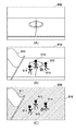
自カメラ画像に応じたカメラアダプタ120の動作について、図7を用いて説明する。図7(A)、(B)、(C)の何れも、サッカーの試合を撮影中にカメラアダプタ120に取り込まれた自カメラ画像であり、それぞれ任意の時間に取り込まれた自カメラ画像である。
Data received by the
-Foreground image and background image separated from the masked image by the foreground background separation unit 124-Three-dimensional model information generated by the generation unit 125-Object extraction image generated by the failure image determination unit 123 (object extraction unit 401) Own camera The operation of the
図7(A)に示す自カメラ画像800は、フィールドでプレーをする選手801、選手802、選手803、およびボール804が撮影された自カメラ画像である。破綻画像判定部123は、このような自カメラ画像800を対象として上記の処理を行うことで、カメラアダプタ120の動作モードとして通常モードを設定する。通常モードに設定されたカメラアダプタ120では、前景背景分離部124は、マスク処理部406によるマスク処理を適用していない自カメラ画像800を前景画像と背景画像とに分離する。また、生成部125は、前景背景分離部124が分離した前景画像とデータ受信部122が受信した上流前景画像とを用いて三次元モデル情報を生成する。また、破綻画像判定部123では、自カメラ画像800からオブジェクト抽出画像を生成する。そして、データ送信部127は、前景画像、背景画像、三次元モデル情報、オブジェクト抽出画像、上流前景画像、上流背景画像、上流三次元モデル情報、上流オブジェクト抽出画像、を隣接する下流のカメラアダプタ120へ送信する。
The self-
図7(B)に示す自カメラ画像810は、カメラレンズに付着したゴミ811とゴミ812が映り込んだ自カメラ画像である。破綻画像判定部123は、このような自カメラ画像810を対象として上記の処理を行うことで、カメラアダプタ120の動作モードとしてマスクモードを設定する。マスクモードに設定されたカメラアダプタ120では、破綻画像判定部123によりオブジェクト抽出画像及びマスク処理済画像が生成される。マスク処理済画像は、自カメラ画像810においてゴミ811及びゴミ812の領域内の画像を、背景画像において対応する領域の画像に置き換えた画像である。前景背景分離部124は、マスク処理部406によるマスク処理を適用したマスク処理済画像を前景画像と背景画像とに分離する。また、生成部125は、前景背景分離部124が分離した前景画像とデータ受信部122が受信した上流前景画像とを用いて三次元モデル情報を生成する。そして、データ送信部127は、前景画像、背景画像、三次元モデル情報、オブジェクト抽出画像、上流前景画像、上流背景画像、上流三次元モデル情報、上流オブジェクト抽出画像、を隣接する下流のカメラアダプタ120へ送信する。
The self-
通常モードとマスクモードとの差分は、自カメラ画像に対してマスク処理を適用するか否かである。マスクモードでも(マスク処理を適用しても)、通常モードと等価な処理を行うことができる。 The difference between the normal mode and the mask mode is whether or not the mask processing is applied to the own camera image. Even in the mask mode (even if the mask processing is applied), the processing equivalent to the normal mode can be performed.
図7(C)に示す自カメラ画像820は、カメラ前の観客821が突如立ち上がったことで映り込んだ自カメラ画像である。破綻画像判定部123は、このような自カメラ画像820を対象として上記の処理を行うことで、カメラアダプタ120の動作モードとしてバイパスモードを設定する。バイパスモードに設定されたカメラアダプタ120では、破綻画像判定部123によりオブジェクト抽出画像が生成される。そしてバイパスモードが設定されている場合には、前景背景分離部124及び生成部125は動作しない。そして、データ送信部127は、オブジェクト抽出画像、上流前景画像、上流背景画像、上流三次元モデル情報、上流オブジェクト抽出画像、を隣接する下流のカメラアダプタ120へ送信する。
The self-
また、データ送信部127は、仮想視点コンテンツを生成するのに不向きな画像(自カメラ画像820)を検出したことを示すエラー情報についても、隣接する下流のカメラアダプタ120に対して送信する。
In addition, the
バイパスモード時、カメラアダプタ120は、上流のカメラアダプタから受信した情報群をそのまま下流のカメラアダプタへ転送するだけでなく、エラー情報についても送信するようにしても良い。この場合、エラー情報を受信した下流のカメラアダプタは、例えば、カメラアダプタ120の代替処理を可能な範囲で実施する。例えば、カメラアダプタ120bからエラー情報がカメラアダプタ120cに対して出力されたとする。このような場合、カメラアダプタ120cは、カメラアダプタ120aによる前景画像とカメラアダプタ120cによる前景画像とを用いて、前景画像、背景画像、三次元モデル情報、オブジェクト抽出画像を生成する。
In the bypass mode, the
以上説明したように、本実施形態によれば、カメラが撮影した画像が仮想視点コンテンツを生成するのに不向きな画像であるか否かを判定し、その判定結果に基づいてカメラアダプタを制御できるようになる。 As described above, according to the present embodiment, it is possible to determine whether or not the image captured by the camera is an image unsuitable for generating virtual viewpoint content, and control the camera adapter based on the determination result. Will be.
[第2の実施形態]
図2,3に示した各機能部は全てハードウェアで実装しても良いし、一部若しくは全部をソフトウェア(コンピュータプログラム)で実装しても良い。後者の場合、例えば、記憶部126をメモリで実装し、それ以外の機能部をコンピュータプログラムで実装しても良く、その場合、このコンピュータプログラムは、カメラアダプタ120内の不図示のプロセッサなどで実行されることになる。
[Second Embodiment]
All the functional parts shown in FIGS. 2 and 3 may be implemented by hardware, or some or all of them may be implemented by software (computer program). In the latter case, for example, the
なお、上述の実施形態では、複数のカメラアダプタ120がデイジーチェーン接続される場合の例を中心に説明したが、この例に限らない。例えば、複数のカメラアダプタ120がスター型のトポロジでサーバ200と接続されても良い。スター型のトポロジを採用した場合の処理の一例について以下に説明する。すなわち、カメラアダプタ120は、図5の処理において無効オブジェクトが存在すると判定した場合、当該無効オブジェクトの領域をマスクしたマスク処理済画像をサーバ200へ出力する。一方、カメラアダプタ120は、撮像画像中に無効オブジェクトが存在しないと判定した場合、撮像画像をサーバ200へ出力する。そして、サーバ200は、各カメラアダプタ120から受信したマスク処理済画像や撮像画像に基づいて仮想視点コンテンツの生成を行う。このような実施形態によっても、仮想視点コンテンツの生成に悪影響を及ぼす原因を抑制ないし排除できる。
In the above-described embodiment, an example in which a plurality of
また、上述の実施形態では、カメラ112とカメラアダプタ120が別々の装置である場合の例を中心に説明したが、この例に限らない。すなわち、カメラアダプタ120の機能がカメラ112によって実現されるようにしても良い。
Further, in the above-described embodiment, an example in which the camera 112 and the
(その他の実施例)
本発明は、上述の実施形態の1以上の機能を実現するプログラムを、ネットワーク又は記憶媒体を介してシステム又は装置に供給し、そのシステム又は装置のコンピュータにおける1つ以上のプロセッサーがプログラムを読出し実行する処理でも実現可能である。また、1以上の機能を実現する回路(例えば、ASIC)によっても実現可能である。
(Other Examples)
The present invention supplies a program that realizes one or more functions of the above-described embodiment to a system or device via a network or storage medium, and one or more processors in the computer of the system or device reads and executes the program. It is also possible to realize the processing. It can also be realized by a circuit (for example, ASIC) that realizes one or more functions.
112a:カメラ 120a:カメラアダプタ
112a:
Claims (11)
前記着目撮像装置による撮像画像に、予め登録された情報に該当するオブジェクトではない無効オブジェクトが含まれている場合には、該撮像画像におけるオブジェクトのサイズ、若しくは前記撮像画像におけるオブジェクトのサイズ及び位置に応じて、前記伝送情報の生成及び伝送を制御する制御手段を備えることを特徴とする前記着目撮像装置の制御装置。 To generate a three-dimensional model of an object in the captured image based on the image captured by the imaging device of interest and the first information transmitted from the control device of the imaging device on the upstream side of the imaging device of interest. A control device of the image pickup device of interest, which generates second information and transmits transmission information including the first information and the second information to a control device of the image pickup device on the downstream side.
When the image captured by the imaging device of interest contains an invalid object that is not an object corresponding to the information registered in advance, the size of the object in the captured image or the size and position of the object in the captured image is set. A control device for the image pickup device of interest, characterized in that the control means for controlling the generation and transmission of the transmission information is provided accordingly.
前記制御装置から伝送された伝送情報に基づいて、指定された視点からの画像を生成する装置と
を有するシステムであって、
着目撮像装置による撮像画像と、該着目撮像装置の上流側の撮像装置の制御装置から伝送された第1の情報と、に基づいて、該撮像画像中のオブジェクトの三次元モデルを生成するための第2の情報を生成し、前記第1の情報と前記第2の情報とを含む伝送情報を、下流側の撮像装置の制御装置に伝送する、該着目撮像装置の制御装置は、
前記着目撮像装置による撮像画像に、予め登録された情報に該当するオブジェクトではない無効オブジェクトが含まれている場合には、該撮像画像におけるオブジェクトのサイズ、若しくは前記撮像画像におけるオブジェクトのサイズ及び位置に応じて、前記伝送情報の生成及び伝送を制御する制御手段を備えることを特徴とするシステム。 Multiple control devices that control each of the multiple imaging devices,
A system including a device that generates an image from a designated viewpoint based on transmission information transmitted from the control device.
To generate a three-dimensional model of an object in the captured image based on the image captured by the imaging device of interest and the first information transmitted from the control device of the imaging device on the upstream side of the imaging device of interest. The control device of the image pickup device of interest, which generates the second information and transmits the transmission information including the first information and the second information to the control device of the image pickup device on the downstream side.
When the image captured by the imaging device of interest contains an invalid object that is not an object corresponding to the information registered in advance, the size of the object in the captured image or the size and position of the object in the captured image is set. A system including a control means for controlling the generation and transmission of the transmission information accordingly.
前記着目撮像装置による撮像画像に、予め登録された情報に該当するオブジェクトではない無効オブジェクトが含まれている場合には、該撮像画像におけるオブジェクトのサイズ、若しくは前記撮像画像におけるオブジェクトのサイズ及び位置に応じて、前記伝送情報の生成及び伝送を制御することを特徴とする前記着目撮像装置の制御装置の制御方法。 To generate a three-dimensional model of an object in the captured image based on the image captured by the imaging device of interest and the first information transmitted from the control device of the imaging device on the upstream side of the imaging device of interest. It is a control method of the control device of the image pickup device of interest, which generates the second information and transmits the transmission information including the first information and the second information to the control device of the image pickup device on the downstream side. hand,
When the image captured by the imaging device of interest contains an invalid object that is not an object corresponding to the information registered in advance, the size of the object in the captured image or the size and position of the object in the captured image is set. A control method for a control device of the imaging device of interest, characterized in that the generation and transmission of the transmission information are controlled accordingly.
Priority Applications (4)
| Application Number | Priority Date | Filing Date | Title |
|---|---|---|---|
| JP2017000709A JP6857032B2 (en) | 2017-01-05 | 2017-01-05 | Control device, system, control method of control device |
| US15/856,327 US10397461B2 (en) | 2017-01-05 | 2017-12-28 | Control apparatus, control method, and non-transitory computer-readable storage medium |
| US16/507,178 US10659673B2 (en) | 2017-01-05 | 2019-07-10 | Control apparatus, control method, and non-transitory computer-readable storage medium |
| JP2021046237A JP2021119459A (en) | 2017-01-05 | 2021-03-19 | Generation device and generation method |
Applications Claiming Priority (1)
| Application Number | Priority Date | Filing Date | Title |
|---|---|---|---|
| JP2017000709A JP6857032B2 (en) | 2017-01-05 | 2017-01-05 | Control device, system, control method of control device |
Related Child Applications (1)
| Application Number | Title | Priority Date | Filing Date |
|---|---|---|---|
| JP2021046237A Division JP2021119459A (en) | 2017-01-05 | 2021-03-19 | Generation device and generation method |
Publications (3)
| Publication Number | Publication Date |
|---|---|
| JP2018109904A JP2018109904A (en) | 2018-07-12 |
| JP2018109904A5 JP2018109904A5 (en) | 2020-02-06 |
| JP6857032B2 true JP6857032B2 (en) | 2021-04-14 |
Family
ID=62711390
Family Applications (2)
| Application Number | Title | Priority Date | Filing Date |
|---|---|---|---|
| JP2017000709A Active JP6857032B2 (en) | 2017-01-05 | 2017-01-05 | Control device, system, control method of control device |
| JP2021046237A Pending JP2021119459A (en) | 2017-01-05 | 2021-03-19 | Generation device and generation method |
Family Applications After (1)
| Application Number | Title | Priority Date | Filing Date |
|---|---|---|---|
| JP2021046237A Pending JP2021119459A (en) | 2017-01-05 | 2021-03-19 | Generation device and generation method |
Country Status (2)
| Country | Link |
|---|---|
| US (2) | US10397461B2 (en) |
| JP (2) | JP6857032B2 (en) |
Families Citing this family (2)
| Publication number | Priority date | Publication date | Assignee | Title |
|---|---|---|---|---|
| JP7250493B2 (en) * | 2018-12-03 | 2023-04-03 | キヤノン株式会社 | Image processing device, method and program for generating three-dimensional shape data |
| CN111901661B (en) * | 2020-07-30 | 2022-05-24 | 海信视像科技股份有限公司 | Video recording method, video playing method and display equipment |
Family Cites Families (11)
| Publication number | Priority date | Publication date | Assignee | Title |
|---|---|---|---|---|
| JP4354708B2 (en) * | 2003-01-15 | 2009-10-28 | 独立行政法人科学技術振興機構 | Multi-view camera system |
| JP2005323330A (en) * | 2004-04-08 | 2005-11-17 | Shimizu Corp | Indoor observation system |
| JP4836086B2 (en) * | 2007-09-10 | 2011-12-14 | 三菱電機株式会社 | 3D shape detector |
| JP4935647B2 (en) * | 2007-11-29 | 2012-05-23 | カシオ計算機株式会社 | Composite image output apparatus and composite image output processing program |
| JP4214291B1 (en) * | 2008-03-26 | 2009-01-28 | 株式会社ザイナス | Grounding point estimation device, grounding point estimation method, flow line display system, and server |
| JP2012015669A (en) | 2010-06-30 | 2012-01-19 | Hitachi Consumer Electronics Co Ltd | Display device and image processing apparatus |
| JP2012175533A (en) * | 2011-02-23 | 2012-09-10 | Sanyo Electric Co Ltd | Electronic apparatus |
| US9681125B2 (en) * | 2011-12-29 | 2017-06-13 | Pelco, Inc | Method and system for video coding with noise filtering |
| JP2014191475A (en) | 2013-03-26 | 2014-10-06 | Honda Motor Co Ltd | Driving support device |
| JP6471541B2 (en) * | 2015-03-05 | 2019-02-20 | サクサ株式会社 | Image processing device |
| US10051180B1 (en) * | 2016-03-04 | 2018-08-14 | Scott Zhihao Chen | Method and system for removing an obstructing object in a panoramic image |
-
2017
- 2017-01-05 JP JP2017000709A patent/JP6857032B2/en active Active
- 2017-12-28 US US15/856,327 patent/US10397461B2/en active Active
-
2019
- 2019-07-10 US US16/507,178 patent/US10659673B2/en active Active
-
2021
- 2021-03-19 JP JP2021046237A patent/JP2021119459A/en active Pending
Also Published As
| Publication number | Publication date |
|---|---|
| US10659673B2 (en) | 2020-05-19 |
| JP2021119459A (en) | 2021-08-12 |
| JP2018109904A (en) | 2018-07-12 |
| US20190335085A1 (en) | 2019-10-31 |
| US20180191941A1 (en) | 2018-07-05 |
| US10397461B2 (en) | 2019-08-27 |
Similar Documents
| Publication | Publication Date | Title |
|---|---|---|
| US11037364B2 (en) | Image processing system for generating a virtual viewpoint image, method of controlling image processing system, and storage medium | |
| US11750792B2 (en) | Information processing apparatus, image generation method, control method, and storage medium | |
| US20230283757A1 (en) | Method for generating virtual viewpoint image and image processing apparatus | |
| KR102121931B1 (en) | Control device, control method and storage medium | |
| JP7121470B2 (en) | Image processing system, control method, and program | |
| JP6957215B2 (en) | Information processing equipment, information processing methods and programs | |
| KR102129792B1 (en) | Information processing device, image generation method, control method and program | |
| US20200329189A1 (en) | Control device, control method, and program | |
| JP6871801B2 (en) | Image processing equipment, image processing method, information processing equipment, imaging equipment and image processing system | |
| JP7179515B2 (en) | Apparatus, control method and program | |
| US10623715B2 (en) | Information processing apparatus and control method therefor | |
| US11095871B2 (en) | System that generates virtual viewpoint image, method and storage medium | |
| US20190082160A1 (en) | Image processing system, image processing apparatus, image processing method, and program | |
| JP2021119459A (en) | Generation device and generation method | |
| JP2019022151A (en) | Information processing apparatus, image processing system, control method, and program | |
| US20180376131A1 (en) | Image processing apparatus, image processing system, and image processing method | |
| JP2019140483A (en) | Image processing system, image processing system control method, transmission device, transmission method, and program | |
| JP7104504B2 (en) | Image processing system, image processing device, image transmission method, and program | |
| JP7134636B2 (en) | Control device, control method and program | |
| JP2021093648A (en) | Image data processing device, image data processing method, and program | |
| JP2021034972A (en) | Information processing system, information processing method, and program | |
| JP2018191236A (en) | Information processing system, information processing method, apparatus, and program |
Legal Events
| Date | Code | Title | Description |
|---|---|---|---|
| A521 | Request for written amendment filed |
Free format text: JAPANESE INTERMEDIATE CODE: A523 Effective date: 20191218 |
|
| A621 | Written request for application examination |
Free format text: JAPANESE INTERMEDIATE CODE: A621 Effective date: 20191218 |
|
| RD01 | Notification of change of attorney |
Free format text: JAPANESE INTERMEDIATE CODE: A7421 Effective date: 20210103 |
|
| A521 | Request for written amendment filed |
Free format text: JAPANESE INTERMEDIATE CODE: A523 Effective date: 20210113 |
|
| TRDD | Decision of grant or rejection written | ||
| A01 | Written decision to grant a patent or to grant a registration (utility model) |
Free format text: JAPANESE INTERMEDIATE CODE: A01 Effective date: 20210219 |
|
| A61 | First payment of annual fees (during grant procedure) |
Free format text: JAPANESE INTERMEDIATE CODE: A61 Effective date: 20210319 |
|
| R151 | Written notification of patent or utility model registration |
Ref document number: 6857032 Country of ref document: JP Free format text: JAPANESE INTERMEDIATE CODE: R151 |