JP6855457B2 - Laparoscopic suture system - Google Patents
Laparoscopic suture system Download PDFInfo
- Publication number
- JP6855457B2 JP6855457B2 JP2018512963A JP2018512963A JP6855457B2 JP 6855457 B2 JP6855457 B2 JP 6855457B2 JP 2018512963 A JP2018512963 A JP 2018512963A JP 2018512963 A JP2018512963 A JP 2018512963A JP 6855457 B2 JP6855457 B2 JP 6855457B2
- Authority
- JP
- Japan
- Prior art keywords
- jaw
- needle
- flip
- assembly
- shim
- Prior art date
- Legal status (The legal status is an assumption and is not a legal conclusion. Google has not performed a legal analysis and makes no representation as to the accuracy of the status listed.)
- Active
Links
- 230000007246 mechanism Effects 0.000 claims description 112
- 230000035515 penetration Effects 0.000 claims description 18
- 238000003860 storage Methods 0.000 claims description 7
- 229920000642 polymer Polymers 0.000 description 13
- 238000003780 insertion Methods 0.000 description 7
- 230000037431 insertion Effects 0.000 description 7
- 230000014759 maintenance of location Effects 0.000 description 6
- 238000005452 bending Methods 0.000 description 5
- 230000006835 compression Effects 0.000 description 5
- 238000007906 compression Methods 0.000 description 5
- 239000000463 material Substances 0.000 description 5
- -1 polypropylene Polymers 0.000 description 4
- 230000013011 mating Effects 0.000 description 3
- 229910001000 nickel titanium Inorganic materials 0.000 description 3
- 230000000149 penetrating effect Effects 0.000 description 3
- 230000004044 response Effects 0.000 description 3
- 125000006850 spacer group Chemical group 0.000 description 3
- 229910001220 stainless steel Inorganic materials 0.000 description 3
- 239000010935 stainless steel Substances 0.000 description 3
- 238000013519 translation Methods 0.000 description 3
- 239000004677 Nylon Substances 0.000 description 2
- 239000004698 Polyethylene Substances 0.000 description 2
- 239000004743 Polypropylene Substances 0.000 description 2
- 230000009471 action Effects 0.000 description 2
- 238000013459 approach Methods 0.000 description 2
- 230000000712 assembly Effects 0.000 description 2
- 238000000429 assembly Methods 0.000 description 2
- 238000002788 crimping Methods 0.000 description 2
- 238000010586 diagram Methods 0.000 description 2
- 239000002184 metal Substances 0.000 description 2
- 229910052751 metal Inorganic materials 0.000 description 2
- HLXZNVUGXRDIFK-UHFFFAOYSA-N nickel titanium Chemical compound [Ti].[Ti].[Ti].[Ti].[Ti].[Ti].[Ti].[Ti].[Ti].[Ti].[Ti].[Ni].[Ni].[Ni].[Ni].[Ni].[Ni].[Ni].[Ni].[Ni].[Ni].[Ni].[Ni].[Ni].[Ni] HLXZNVUGXRDIFK-UHFFFAOYSA-N 0.000 description 2
- 229920001778 nylon Polymers 0.000 description 2
- 229920000728 polyester Polymers 0.000 description 2
- 229920000573 polyethylene Polymers 0.000 description 2
- 229920001155 polypropylene Polymers 0.000 description 2
- 238000001356 surgical procedure Methods 0.000 description 2
- 238000003466 welding Methods 0.000 description 2
- 229920000178 Acrylic resin Polymers 0.000 description 1
- 239000004925 Acrylic resin Substances 0.000 description 1
- 229910001369 Brass Inorganic materials 0.000 description 1
- 229910000906 Bronze Inorganic materials 0.000 description 1
- MBXCVSANAPSXKM-UHFFFAOYSA-N CC1C#CCC1 Chemical compound CC1C#CCC1 MBXCVSANAPSXKM-UHFFFAOYSA-N 0.000 description 1
- 241001631457 Cannula Species 0.000 description 1
- 229920000049 Carbon (fiber) Polymers 0.000 description 1
- AEMRFAOFKBGASW-UHFFFAOYSA-N Glycolic acid Polymers OCC(O)=O AEMRFAOFKBGASW-UHFFFAOYSA-N 0.000 description 1
- 239000004696 Poly ether ether ketone Substances 0.000 description 1
- 229920000954 Polyglycolide Polymers 0.000 description 1
- 239000004793 Polystyrene Substances 0.000 description 1
- RTAQQCXQSZGOHL-UHFFFAOYSA-N Titanium Chemical compound [Ti] RTAQQCXQSZGOHL-UHFFFAOYSA-N 0.000 description 1
- HZEWFHLRYVTOIW-UHFFFAOYSA-N [Ti].[Ni] Chemical compound [Ti].[Ni] HZEWFHLRYVTOIW-UHFFFAOYSA-N 0.000 description 1
- DHKHKXVYLBGOIT-UHFFFAOYSA-N acetaldehyde Diethyl Acetal Natural products CCOC(C)OCC DHKHKXVYLBGOIT-UHFFFAOYSA-N 0.000 description 1
- 125000002777 acetyl group Chemical class [H]C([H])([H])C(*)=O 0.000 description 1
- 229920000122 acrylonitrile butadiene styrene Polymers 0.000 description 1
- 239000004676 acrylonitrile butadiene styrene Substances 0.000 description 1
- 230000004913 activation Effects 0.000 description 1
- 239000000853 adhesive Substances 0.000 description 1
- 230000001070 adhesive effect Effects 0.000 description 1
- 229910045601 alloy Inorganic materials 0.000 description 1
- 239000000956 alloy Substances 0.000 description 1
- 229910052782 aluminium Inorganic materials 0.000 description 1
- XAGFODPZIPBFFR-UHFFFAOYSA-N aluminium Chemical compound [Al] XAGFODPZIPBFFR-UHFFFAOYSA-N 0.000 description 1
- JUPQTSLXMOCDHR-UHFFFAOYSA-N benzene-1,4-diol;bis(4-fluorophenyl)methanone Chemical compound OC1=CC=C(O)C=C1.C1=CC(F)=CC=C1C(=O)C1=CC=C(F)C=C1 JUPQTSLXMOCDHR-UHFFFAOYSA-N 0.000 description 1
- 239000010951 brass Substances 0.000 description 1
- 238000005219 brazing Methods 0.000 description 1
- 239000010974 bronze Substances 0.000 description 1
- 239000004917 carbon fiber Substances 0.000 description 1
- 239000002729 catgut Substances 0.000 description 1
- 229920001577 copolymer Polymers 0.000 description 1
- KUNSUQLRTQLHQQ-UHFFFAOYSA-N copper tin Chemical compound [Cu].[Sn] KUNSUQLRTQLHQQ-UHFFFAOYSA-N 0.000 description 1
- 238000000354 decomposition reaction Methods 0.000 description 1
- 230000006837 decompression Effects 0.000 description 1
- 238000006073 displacement reaction Methods 0.000 description 1
- 230000009977 dual effect Effects 0.000 description 1
- 239000012530 fluid Substances 0.000 description 1
- 230000035876 healing Effects 0.000 description 1
- 238000001746 injection moulding Methods 0.000 description 1
- 230000003993 interaction Effects 0.000 description 1
- 238000005304 joining Methods 0.000 description 1
- 238000002357 laparoscopic surgery Methods 0.000 description 1
- 150000002739 metals Chemical class 0.000 description 1
- VNWKTOKETHGBQD-UHFFFAOYSA-N methane Chemical compound C VNWKTOKETHGBQD-UHFFFAOYSA-N 0.000 description 1
- 238000000034 method Methods 0.000 description 1
- 238000002324 minimally invasive surgery Methods 0.000 description 1
- 238000012978 minimally invasive surgical procedure Methods 0.000 description 1
- 238000012986 modification Methods 0.000 description 1
- 230000004048 modification Effects 0.000 description 1
- 210000002569 neuron Anatomy 0.000 description 1
- 239000004033 plastic Substances 0.000 description 1
- 229920003023 plastic Polymers 0.000 description 1
- 229920000747 poly(lactic acid) Polymers 0.000 description 1
- 229920002463 poly(p-dioxanone) polymer Polymers 0.000 description 1
- 229920001610 polycaprolactone Polymers 0.000 description 1
- 239000004632 polycaprolactone Substances 0.000 description 1
- 239000004417 polycarbonate Substances 0.000 description 1
- 229920000515 polycarbonate Polymers 0.000 description 1
- 239000000622 polydioxanone Substances 0.000 description 1
- 229920002530 polyetherether ketone Polymers 0.000 description 1
- 239000004626 polylactic acid Substances 0.000 description 1
- 229920002223 polystyrene Polymers 0.000 description 1
- 229920002635 polyurethane Polymers 0.000 description 1
- 239000004814 polyurethane Substances 0.000 description 1
- 229920000915 polyvinyl chloride Polymers 0.000 description 1
- 239000004800 polyvinyl chloride Substances 0.000 description 1
- 230000002980 postoperative effect Effects 0.000 description 1
- 230000037390 scarring Effects 0.000 description 1
- 238000005476 soldering Methods 0.000 description 1
- 238000003856 thermoforming Methods 0.000 description 1
- 239000010936 titanium Substances 0.000 description 1
- 229910052719 titanium Inorganic materials 0.000 description 1
- 238000012546 transfer Methods 0.000 description 1
- WFKWXMTUELFFGS-UHFFFAOYSA-N tungsten Chemical compound [W] WFKWXMTUELFFGS-UHFFFAOYSA-N 0.000 description 1
- 229910052721 tungsten Inorganic materials 0.000 description 1
- 239000010937 tungsten Substances 0.000 description 1
Images


Classifications
-
- A—HUMAN NECESSITIES
- A61—MEDICAL OR VETERINARY SCIENCE; HYGIENE
- A61B—DIAGNOSIS; SURGERY; IDENTIFICATION
- A61B17/00—Surgical instruments, devices or methods, e.g. tourniquets
- A61B17/04—Surgical instruments, devices or methods, e.g. tourniquets for suturing wounds; Holders or packages for needles or suture materials
- A61B17/0469—Suturing instruments for use in minimally invasive surgery, e.g. endoscopic surgery
-
- A—HUMAN NECESSITIES
- A61—MEDICAL OR VETERINARY SCIENCE; HYGIENE
- A61B—DIAGNOSIS; SURGERY; IDENTIFICATION
- A61B17/00—Surgical instruments, devices or methods, e.g. tourniquets
- A61B17/04—Surgical instruments, devices or methods, e.g. tourniquets for suturing wounds; Holders or packages for needles or suture materials
- A61B17/0482—Needle or suture guides
-
- A—HUMAN NECESSITIES
- A61—MEDICAL OR VETERINARY SCIENCE; HYGIENE
- A61B—DIAGNOSIS; SURGERY; IDENTIFICATION
- A61B17/00—Surgical instruments, devices or methods, e.g. tourniquets
- A61B17/04—Surgical instruments, devices or methods, e.g. tourniquets for suturing wounds; Holders or packages for needles or suture materials
- A61B17/0485—Devices or means, e.g. loops, for capturing the suture thread and threading it through an opening of a suturing instrument or needle eyelet
-
- A—HUMAN NECESSITIES
- A61—MEDICAL OR VETERINARY SCIENCE; HYGIENE
- A61B—DIAGNOSIS; SURGERY; IDENTIFICATION
- A61B17/00—Surgical instruments, devices or methods, e.g. tourniquets
- A61B17/04—Surgical instruments, devices or methods, e.g. tourniquets for suturing wounds; Holders or packages for needles or suture materials
- A61B17/06—Needles ; Sutures; Needle-suture combinations; Holders or packages for needles or suture materials
- A61B17/06166—Sutures
-
- A—HUMAN NECESSITIES
- A61—MEDICAL OR VETERINARY SCIENCE; HYGIENE
- A61B—DIAGNOSIS; SURGERY; IDENTIFICATION
- A61B17/00—Surgical instruments, devices or methods, e.g. tourniquets
- A61B17/04—Surgical instruments, devices or methods, e.g. tourniquets for suturing wounds; Holders or packages for needles or suture materials
- A61B17/06—Needles ; Sutures; Needle-suture combinations; Holders or packages for needles or suture materials
- A61B17/062—Needle manipulators
- A61B17/0625—Needle manipulators the needle being specially adapted to interact with the manipulator, e.g. being ridged to snap fit in a hole of the manipulator
-
- A—HUMAN NECESSITIES
- A61—MEDICAL OR VETERINARY SCIENCE; HYGIENE
- A61B—DIAGNOSIS; SURGERY; IDENTIFICATION
- A61B17/00—Surgical instruments, devices or methods, e.g. tourniquets
- A61B17/04—Surgical instruments, devices or methods, e.g. tourniquets for suturing wounds; Holders or packages for needles or suture materials
- A61B17/0401—Suture anchors, buttons or pledgets, i.e. means for attaching sutures to bone, cartilage or soft tissue; Instruments for applying or removing suture anchors
- A61B2017/0417—T-fasteners
-
- A—HUMAN NECESSITIES
- A61—MEDICAL OR VETERINARY SCIENCE; HYGIENE
- A61B—DIAGNOSIS; SURGERY; IDENTIFICATION
- A61B17/00—Surgical instruments, devices or methods, e.g. tourniquets
- A61B17/04—Surgical instruments, devices or methods, e.g. tourniquets for suturing wounds; Holders or packages for needles or suture materials
- A61B17/06—Needles ; Sutures; Needle-suture combinations; Holders or packages for needles or suture materials
- A61B17/06004—Means for attaching suture to needle
- A61B2017/06009—Means for attaching suture to needle having additional means for releasably clamping the suture to the needle, e.g. actuating rod slideable within the needle
-
- A—HUMAN NECESSITIES
- A61—MEDICAL OR VETERINARY SCIENCE; HYGIENE
- A61B—DIAGNOSIS; SURGERY; IDENTIFICATION
- A61B17/00—Surgical instruments, devices or methods, e.g. tourniquets
- A61B17/04—Surgical instruments, devices or methods, e.g. tourniquets for suturing wounds; Holders or packages for needles or suture materials
- A61B17/06—Needles ; Sutures; Needle-suture combinations; Holders or packages for needles or suture materials
- A61B17/06004—Means for attaching suture to needle
- A61B2017/06019—Means for attaching suture to needle by means of a suture-receiving lateral eyelet machined in the needle
-
- A—HUMAN NECESSITIES
- A61—MEDICAL OR VETERINARY SCIENCE; HYGIENE
- A61B—DIAGNOSIS; SURGERY; IDENTIFICATION
- A61B17/00—Surgical instruments, devices or methods, e.g. tourniquets
- A61B17/04—Surgical instruments, devices or methods, e.g. tourniquets for suturing wounds; Holders or packages for needles or suture materials
- A61B17/06—Needles ; Sutures; Needle-suture combinations; Holders or packages for needles or suture materials
- A61B17/06004—Means for attaching suture to needle
- A61B2017/06033—Means for attaching suture to needle using adhesives
-
- A—HUMAN NECESSITIES
- A61—MEDICAL OR VETERINARY SCIENCE; HYGIENE
- A61B—DIAGNOSIS; SURGERY; IDENTIFICATION
- A61B17/00—Surgical instruments, devices or methods, e.g. tourniquets
- A61B17/04—Surgical instruments, devices or methods, e.g. tourniquets for suturing wounds; Holders or packages for needles or suture materials
- A61B17/06—Needles ; Sutures; Needle-suture combinations; Holders or packages for needles or suture materials
- A61B17/06004—Means for attaching suture to needle
- A61B2017/06038—Means for attaching suture to needle soldered or brazed or welded
-
- A—HUMAN NECESSITIES
- A61—MEDICAL OR VETERINARY SCIENCE; HYGIENE
- A61B—DIAGNOSIS; SURGERY; IDENTIFICATION
- A61B17/00—Surgical instruments, devices or methods, e.g. tourniquets
- A61B17/04—Surgical instruments, devices or methods, e.g. tourniquets for suturing wounds; Holders or packages for needles or suture materials
- A61B17/06—Needles ; Sutures; Needle-suture combinations; Holders or packages for needles or suture materials
- A61B17/06004—Means for attaching suture to needle
- A61B2017/06047—Means for attaching suture to needle located at the middle of the needle
-
- A—HUMAN NECESSITIES
- A61—MEDICAL OR VETERINARY SCIENCE; HYGIENE
- A61B—DIAGNOSIS; SURGERY; IDENTIFICATION
- A61B17/00—Surgical instruments, devices or methods, e.g. tourniquets
- A61B17/04—Surgical instruments, devices or methods, e.g. tourniquets for suturing wounds; Holders or packages for needles or suture materials
- A61B17/06—Needles ; Sutures; Needle-suture combinations; Holders or packages for needles or suture materials
- A61B17/06066—Needles, e.g. needle tip configurations
- A61B2017/0609—Needles, e.g. needle tip configurations having sharp tips at both ends, e.g. shuttle needle alternately retained and released by first and second facing jaws of a suturing instrument
-
- A—HUMAN NECESSITIES
- A61—MEDICAL OR VETERINARY SCIENCE; HYGIENE
- A61B—DIAGNOSIS; SURGERY; IDENTIFICATION
- A61B17/00—Surgical instruments, devices or methods, e.g. tourniquets
- A61B17/04—Surgical instruments, devices or methods, e.g. tourniquets for suturing wounds; Holders or packages for needles or suture materials
- A61B17/06—Needles ; Sutures; Needle-suture combinations; Holders or packages for needles or suture materials
- A61B17/06166—Sutures
- A61B2017/06176—Sutures with protrusions, e.g. barbs
Description
本願は、外科用器械、特に組織を縫合するための腹腔鏡下外科用器具に関する。 The present application relates to surgical instruments, in particular laparoscopic surgical instruments for suturing tissue.
〔関連出願の説明〕
本願は、2015年9月11日に出願され、現在係属中の米国特許仮出願第62/217,502号(発明の名称:LAPAROSCOPIC SUTURING SYSTEM)の権益主張出願である。この出願を参照により引用し、その記載内容全体を本明細書の一部とする。
[Explanation of related applications]
This application is a claim application of US Patent Provisional Application No. 62 / 217,502 (title of invention: LAPAROSCOPIC SUTURING SYSTEM), which was filed on September 11, 2015 and is currently pending. This application is cited by reference and its entire description is incorporated herein by reference.
手術部位にポートから接近する外科的処置、例えば低侵襲外科的処置では、比較的小径のポートを通って手術部位まで前進させることができる縫合ツールを用いて組織を縫合することが望ましい場合がある。縫合ツールは、針およびこれに取り付けられた縫合糸を手術部位の組織に通して前進させてオペレータが組織を近づけるランニングステッチを作ることができるようにするよう構成されているのが良い。針の長手方向軸線がトロカールの軸線に垂直になっている状態でトロカールに沿って下降する縫合器具が製作されており、それによりこの器具内で使用できる針の長さがトロカールの内径に制限される。さらに、現行の縫合器具は、典型的には、操作するのが複雑かつやっかいである作動機構体を有し、それにより単一のステッチを完成させるのに多数回の操作ステップが必要である。望ましくは、改良型縫合器具が高い効率、高い簡便性および高い使用のしやすさを提供するのが良い。 For surgical procedures that approach the surgical site from the port, such as minimally invasive surgical procedures, it may be desirable to suture the tissue with a suture tool that can advance to the surgical site through a relatively small diameter port. .. The suture tool should be configured so that the needle and the suture attached to it can be advanced through the tissue at the surgical site to allow the operator to create a running stitch that brings the tissue closer. A suture device has been made that descends along the trocar with the longitudinal axis of the needle perpendicular to the axis of the trocar, which limits the length of the needle that can be used within this device to the inner diameter of the trocar. To. In addition, current suturing instruments typically have an actuating mechanism that is complex and cumbersome to operate, which requires multiple operating steps to complete a single stitch. Desirably, the improved suturing device should provide high efficiency, high convenience and high ease of use.
ある特定の実施形態では、腹腔鏡下縫合器具が本明細書において提供される。腹腔鏡下縫合器具は、ハンドル組立体、細長いシャフト、ジョー組立体、および針を有する。ハンドル組立体は、近位端部および遠位端部を備えている。細長いシャフトは、ハンドル組立体の遠位端部から遠位側に延びていて長手方向中心軸線を定めている。ジョー組立体は、細長いシャフトから遠位側に延びている。ジョー組立体は、各々が細長いシャフトに回動可能に結合された近位端部と、遠位端部とを備えた第1のジョーおよび第2のジョーを含む。ジョー組立体および針は、針が第1のジョーおよび第2のジョーのうちの一方内に位置決めされるとともに、第1のジョー、第2のジョー、および針が長手方向中心軸線と全体として整列した格納形態と、第1のジョー、第2のジョー、および針が長手方向中心軸線に対して横断方向に延びる開き位置との間で選択的に位置決め可能である。 In certain embodiments, laparoscopic suturing devices are provided herein. The laparoscopic suture device has a handle assembly, an elongated shaft, a jaw assembly, and a needle. The handle assembly comprises a proximal end and a distal end. The elongated shaft extends distally from the distal end of the handle assembly and defines the longitudinal central axis. The jaw assembly extends distally from the elongated shaft. The jaw assembly includes a first jaw and a second jaw each having a proximal end rotatably coupled to an elongated shaft and a distal end. The jaw assembly and needle are such that the needle is positioned within one of the first and second jaws and the first jaw, second jaw, and needle are aligned as a whole with the longitudinal center axis. It is possible to selectively position the retracted form and the opening position where the first jaw, the second jaw, and the needle extend in the transverse direction with respect to the central axis in the longitudinal direction.
ある特定の実施形態では、腹腔鏡下縫合器具が本明細書において提供される。腹腔鏡下縫合器具は、ハンドル組立体、細長いシャフト、ジョー組立体、および針を有する。ハンドル組立体は、近位端部および遠位端部を備えている。ハンドル組立体は、トリガ機構体、クロージャ機構体、およびトグル機構体を含む。細長いシャフトは、ハンドル組立体の遠位端部から遠位側に延びていて長手方向中心軸線を定めている。ジョー組立体は、細長いシャフトから遠位側に延びている。ジョー組立体は、各々が細長いシャフトに回動可能に結合された近位端部と、遠位端部とを備えた第1のジョーおよび第2のジョーを含む。トリガ機構体は、トリガ機構体の作動サイクルが順次、クロージャ機構体を作動させてジョー組立体の第1のジョーおよび第2のジョーを閉じ、トグル機構体を作動させて針を第1のジョーおよび第2のジョーのうちの一方から第1のジョーおよび第2のジョーの他方に移送し、クロージャ機構体を作動させて第1のジョーおよび第2のジョーを開くようクロージャ機構体およびトグル機構体に作動可能に結合されている。 In certain embodiments, laparoscopic suturing devices are provided herein. The laparoscopic suture device has a handle assembly, an elongated shaft, a jaw assembly, and a needle. The handle assembly comprises a proximal end and a distal end. The handle assembly includes a trigger mechanism, a closure mechanism, and a toggle mechanism. The elongated shaft extends distally from the distal end of the handle assembly and defines the longitudinal central axis. The jaw assembly extends distally from the elongated shaft. The jaw assembly includes a first jaw and a second jaw each having a proximal end rotatably coupled to an elongated shaft and a distal end. In the trigger mechanism, the operation cycle of the trigger mechanism sequentially activates the closure mechanism to close the first jaw and the second jaw of the jaw assembly, and activates the toggle mechanism to move the needle to the first jaw. And the closure mechanism and toggle mechanism to transfer from one of the second jaws to the other of the first and second jaws and activate the closure mechanism to open the first and second jaws. It is operably connected to the body.
ある特定の実施形態では、腹腔鏡下縫合システムが本明細書において提供される。腹腔鏡下縫合システムは、腹腔鏡下縫合器具および縫合針を含む。腹腔鏡下縫合器具は、ハンドル組立体、細長いシャフト、およびジョー組立体を有する。細長いシャフトは、ハンドル組立体に結合された近位端部と、遠位端部とを備えている。細長いシャフトは、近位端部と遠位端部との間に延びる長手方向中心軸線を定めている。ジョー組立体は、細長いシャフトの遠位端部に結合されている。ジョー組立体は、各々細長いシャフトに回動可能に結合された第1のジョーと第2のジョーを含み、第1のジョーおよび第2のジョーは、開き形態と閉じ形態との間で回動可能である。縫合針は、ジョー組立体内に位置決め可能である。縫合針は、針および針に結合された縫合糸を有する。針は、全体として湾曲したプロフィールを有していて第1の穿通先端部から第2の穿通先端部まで延びている。針は、第1の穿通先端部に隣接して位置する第1のシム切欠きと、第2の穿通先端部に隣接して位置する第2のシム切欠きと、第1の穿通先端部に隣接して位置する第1の凹部と、第2の穿通先端部に隣接して位置する第2の凹部とを有する。 In certain embodiments, a laparoscopic suturing system is provided herein. The laparoscopic suture system includes a laparoscopic suture device and a suture needle. The laparoscopic suture device has a handle assembly, an elongated shaft, and a jaw assembly. The elongated shaft comprises a proximal end coupled to the handle assembly and a distal end. The elongated shaft defines a longitudinal central axis extending between the proximal and distal ends. The jaw assembly is attached to the distal end of the elongated shaft. The jaw assembly includes a first jaw and a second jaw, each rotatably coupled to an elongated shaft, the first jaw and the second jaw rotating between an open form and a closed form. It is possible. The suture needle can be positioned within the jaw assembly. The suture needle has a needle and a suture attached to the needle. The needle has a curved profile as a whole and extends from the first penetration tip to the second penetration tip. The needle is provided in the first shim notch located adjacent to the first penetration tip, the second shim notch located adjacent to the second penetration tip, and the first penetration tip. It has a first recess located adjacent to it and a second recess located adjacent to the second penetration tip.
ある特定の実施形態では、腹腔鏡下縫合器具が本明細書において提供される。腹腔鏡下縫合器具は、ハンドル組立体と、細長いシャフトと、ジョー組立体とを有する。ハンドル組立体は、近位端部および遠位端部を含む。細長いシャフトは、ハンドル組立体の遠位端部から遠位側に延びていて長手方向中心軸線を定めている。ジョー組立体は、細長いシャフトに回動可能に結合された近位端部と、遠位端部とを含む。ジョー組立体は、第1のジョーおよび第2のジョーを含む。第1のジョーは、ジョー組立体の近位端部のところに位置した第1のベースジョーと、ジョー組立体の遠位端部のところに位置した第1のフリップジョーとを含む。第1のフリップジョーは、第1のベースジョーに回動可能に結合されている。第1のフリップジョーは、第1の針チャネルを有する。第1のフリップジョーは、第1のベースジョーに対して全体として長手方向に差し向けられた格納またはしまい込み位置と、第1の針チャネルが第1のベースジョーに対して横断方向に差し向けられた縫合位置との間で回動可能である。第2のジョーは、ジョー組立体の近位端部のところに位置した第2のベースジョーと、ジョー組立体の遠位端部のところに位置した第2のフリップジョーとを含む。第2のベースジョーは、第1のベースジョーおよび細長いシャフトに回動可能に結合されている。第2のフリップジョーは、第2のベースジョーに回動可能に結合されている。第2のフリップジョーは、第2の針チャネルを有する。第2のフリップジョーは、第2のベースジョーに対して全体として長手方向に差し向けられた格納またはしまい込み位置と、第2の針チャネルが第2のベースジョーに対して横断方向に差し向けられた縫合位置との間で回動可能である。 In certain embodiments, laparoscopic suturing devices are provided herein. The laparoscopic suture device has a handle assembly, an elongated shaft, and a jaw assembly. The handle assembly includes a proximal end and a distal end. The elongated shaft extends distally from the distal end of the handle assembly and defines the longitudinal central axis. The jaw assembly includes a proximal end rotatably coupled to an elongated shaft and a distal end. The jaw assembly includes a first jaw and a second jaw. The first jaws include a first base jaw located at the proximal end of the jaw assembly and a first flip jaw located at the distal end of the jaw assembly. The first flip jaw is rotatably coupled to the first base jaw. The first flip jaw has a first needle channel. The first flip jaw has a retracted or stowed position that is generally longitudinally directed with respect to the first base jaw and a first needle channel directed transversely with respect to the first base jaw. It is rotatable to and from the stitched position. The second jaw includes a second base jaw located at the proximal end of the jaw assembly and a second flip jaw located at the distal end of the jaw assembly. The second base jaw is rotatably coupled to the first base jaw and the elongated shaft. The second flip jaw is rotatably coupled to the second base jaw. The second flip jaw has a second needle channel. The second flip jaw has a retracted or stowed position that is generally longitudinally directed with respect to the second base jaw and a second needle channel directed laterally with respect to the second base jaw. It is rotatable to and from the stitched position.
ある特定の実施形態では、腹腔鏡下縫合器具が本明細書において提供される。腹腔鏡下縫合器具は、ハンドル組立体と、細長いシャフトと、ジョー組立体とを有する。ハンドル組立体は、近位端部および遠位端部を含む。ハンドル組立体は、ハンドル本体、トリガ、およびトグル機構体を含む。トリガは、ハンドル本体に回動可能に結合されている。トグル機構体は、ハンドル本体に対するトリガの回動運動によって作動可能である。トグル機構体は、トグル管、第1のシム、および第2のシムを含む。トグル管は、トリガの回動運動に応動してハンドル本体内で回転可能である。トグル管は、シムガイドを有する。第1のシムは、シムガイド内に位置決めされた第1のフォロワを備えた近位端部を有する。第1のシムは、トグル管の回転によって長手方向に動くことができる。第2のシムは、シムガイド内に位置決めされた第2のフォロワを備えた近位端部を有する。第2のシムは、トグル管の回転によって長手方向に動くことができる。細長いシャフトは、ハンドル組立体の遠位端部から遠位側に延びていて長手方向中心軸線を定める。ジョー組立体は、細長いシャフトから遠位側に延びている。ジョー組立体は、細長いシャフトに回動可能に結合された近位端部と、遠位端部とを含む。ジョー組立体は、第1のジョーおよび第2のジョーを含む。第1のジョーは、細長いシャフトに回動可能に結合された近位端部および第1の針保持スロットが設けられた遠位端部を有する。第2のジョーは、細長いシャフトに回動可能に結合された近位端部および第2の針保持スロットが設けられた遠位端部を有する。第1のシムは、第1のジョー内に位置決めされた遠位端部まで遠位側に延び、第2のシムは、第2のジョー内に位置決めされた遠位端部まで遠位側に延びている。トグル機構体は、交互に第1の針保持スロットに隣接して位置する第1のシムの遠位端部を長手方向に前進させたり、第2の針保持スロットに隣接して位置する第2のシムの遠位端部を長手方向に前進させたりするようトグルサイクルで動作可能である。 In certain embodiments, laparoscopic suturing devices are provided herein. The laparoscopic suture device has a handle assembly, an elongated shaft, and a jaw assembly. The handle assembly includes a proximal end and a distal end. The handle assembly includes a handle body, a trigger, and a toggle mechanism. The trigger is rotatably coupled to the handle body. The toggle mechanism can be actuated by the rotational movement of the trigger with respect to the handle body. The toggle mechanism includes a toggle tube, a first shim, and a second shim. The toggle tube can rotate in the handle body in response to the rotational movement of the trigger. The toggle tube has a shim guide. The first shim has a proximal end with a first follower positioned within the shim guide. The first shim can be moved longitudinally by the rotation of the toggle tube. The second shim has a proximal end with a second follower positioned within the shim guide. The second shim can be moved longitudinally by the rotation of the toggle tube. The elongated shaft extends distally from the distal end of the handle assembly and defines the longitudinal central axis. The jaw assembly extends distally from the elongated shaft. The jaw assembly includes a proximal end rotatably coupled to an elongated shaft and a distal end. The jaw assembly includes a first jaw and a second jaw. The first jaw has a proximal end rotatably coupled to an elongated shaft and a distal end provided with a first needle holding slot. The second jaw has a proximal end rotatably coupled to an elongated shaft and a distal end provided with a second needle holding slot. The first shim extends distally to the distal end positioned within the first jaw, and the second shim extends distally to the distal end positioned within the second jaw. It is extending. The toggle mechanism alternately advances the distal end of the first shim, which is located adjacent to the first needle holding slot, in the longitudinal direction, or a second, which is located adjacent to the second needle holding slot. It can be operated in a toggle cycle to advance the distal end of the shim in the longitudinal direction.
ある特定の実施形態では、腹腔鏡下縫合器具が本明細書において提供される。腹腔鏡下縫合器具は、ハンドル組立体と、細長いシャフトと、およびジョー組立体とを有する。ハンドル組立体は、近位端部および遠位端部を含む。ハンドル組立体は、ラッチ留め形態と、ラッチ外し形態を有するラッチ機構体を含む。細長いシャフトは、ハンドル組立体の遠位端部から遠位側に延びて長手方向中心軸線を定めている。ジョー組立体は、細長いシャフトから遠位側に延びている。ジョー組立体は、細長いシャフトに回動可能に結合された近位端部と、遠位端部とを含む。ジョー組立体は、第1のジョーおよび第2のジョーを含む。第1のジョーは、第1のベースジョーおよび第1のフリップジョーを含む。第1のベースジョーは、ジョー組立体の近位端部のところに位置している。第1のフリップジョーは、ジョー組立体の遠位端部のところに位置していて第1のベースジョーに回動可能に結合されている。第1のフリップジョーは、ジョー組立体の小径プロフィールを定める格納位置と縫合位置との間で回動可能である。第2のジョーは、第2のベースジョーおよび第2のフリップジョーを含む。第2のベースジョーは、ジョー組立体の近位端部のところに位置していて第1のベースジョーおよび細長いシャフトに回動可能に結合されている。第2のフリップジョーは、ジョー組立体の遠位端部のところに位置していて第2のベースジョーに回動可能に結合されている。第2のフリップジョーは、ジョー組立体の小径プロフィールを定める格納位置と縫合位置との間で回動可能である。ラッチ機構体は、ラッチ機構体がラッチ留め位置にある状態で第1のフリップジョーおよび第2のフリップジョーが格納位置に保持され、ラッチ機構体がラッチ外し位置にある状態では第1のフリップジョーおよび第2のフリップジョーが縫合位置まで回動可能であるように第1のフリップジョーおよび第2のフリップジョーに作動可能に結合されている。 In certain embodiments, laparoscopic suturing devices are provided herein. The laparoscopic suture device has a handle assembly, an elongated shaft, and a jaw assembly. The handle assembly includes a proximal end and a distal end. The handle assembly includes a latch mechanism body having a latch fastening form and a latch release form. The elongated shaft extends distally from the distal end of the handle assembly to define the longitudinal central axis. The jaw assembly extends distally from the elongated shaft. The jaw assembly includes a proximal end rotatably coupled to an elongated shaft and a distal end. The jaw assembly includes a first jaw and a second jaw. The first jaw includes a first base jaw and a first flip jaw. The first base jaw is located at the proximal end of the jaw assembly. The first flip jaw is located at the distal end of the jaw assembly and is rotatably coupled to the first base jaw. The first flip jaw is rotatable between a retracted position and a suture position that define the small diameter profile of the jaw assembly. The second jaw includes a second base jaw and a second flip jaw. The second base jaw is located at the proximal end of the jaw assembly and is rotatably coupled to the first base jaw and the elongated shaft. The second flip jaw is located at the distal end of the jaw assembly and is rotatably coupled to the second base jaw. The second flip jaw is rotatable between a retracted position and a suture position that define the small diameter profile of the jaw assembly. In the latch mechanism, the first flip jaw and the second flip jaw are held in the retracted position when the latch mechanism is in the latching position, and the first flip jaw is held in the state where the latch mechanism is in the unlatch position. And the second flip jaw is operably coupled to the first flip jaw and the second flip jaw so that it can rotate to the suture position.
種々の実施形態では、縫合システムが本明細書において開示され、この縫合システムは、例えば腹腔鏡下手術のような低侵襲手術中、縫合糸を患者の体内の組織に付ける際の外科医の効率を向上させることができる。縫合器具は、縫合糸が取り付けられた針を、ジョー組立体のジョー相互間で組織の辺縁を交互に行ったり来たりするように通し、これは、針を組織中に刺入し、そして駆動ジョーが針を把持している間、受け取りジョーを用いて針を把持することによって行われる。 In various embodiments, a suture system is disclosed herein, which improves the surgeon's efficiency in attaching sutures to tissues within the patient's body during minimally invasive surgery, such as laparoscopic surgery. Can be improved. The suture device passes a suture-attached needle back and forth between the jaws of the jaw assembly, alternating between the edges of the tissue, which inserts the needle into the tissue and then. This is done by gripping the needle with the receiving jaw while the drive jaw grips the needle.
臨床的使用中、接近器具、例えばトロカールを最初に体壁に通して体腔内に配置し、トロカールカニューレを体腔内にかつ体壁を横切って配置したままにする。本明細書において説明する縫合器具は、両端に鋭利な箇所を備えた針の中心に取り付けられている縫合糸を利用することができ、したがって、針を組織の辺縁を交互に行ったり来たりするように通すことができる。この器具を比較的小径なトロカール、例えば5mmトロカールに沿って下へ嵌めるため、針をトロカールに通して挿入および取り出し中、格納するのが良く、その目的は、縫合器具の直径プロフィールを低くすることにある。針を格納する際、縫合器具は、非動作または格納状態にあると考えられる。体腔内に位置している場合または体外での針装填中、縫合器具をその動作または縫合状態に展開することができる。縫合器具は、その動作状態にある間、縫合針を組織に刺入して針およびこれに取り付けられた縫合糸を駆動ジョーから受け取りジョーに渡すことができる。 During clinical use, an approach device, such as a trocar, is first placed through the body cavity into the body cavity and the trocar cannula remains placed within the body cavity and across the body wall. The sutures described herein can utilize sutures that are attached to the center of the needle with sharp edges at both ends, thus alternating the needle back and forth between the edges of the tissue. Can be passed through. Since this instrument fits down along a relatively small diameter trocar, such as a 5 mm trocar, it is better to store the needle during insertion and removal through the trocar, the purpose of which is to lower the diameter profile of the suturing instrument. It is in. When retracting the needle, the suture device is considered to be inactive or retracted. The suturing device can be deployed to its movement or sutured state when located in the body cavity or during needle loading outside the body. While in its operating state, the suture device can insert the suture needle into the tissue to receive the needle and the suture attached to it from the drive jaw and pass it to the jaw.
有利には、本明細書において説明する縫合器具の格納針形態により、もしそのようにしなければ5mmトロカールに沿って下へ嵌めることができない長さを備えた針を使用することができる。外科医が小径トロカールを用いることができるということは、顕著な利点をもたらし、例えば、患者の術後治癒時間および瘢痕化を軽減することができる。トロカールの大きな通常サイズ、例えば10mm、12mmおよび15mmでは、5mmトロカールよりもかなり大きな切開創が必要である。本明細書において説明する縫合器具の格納形態は、従来型縫合器具の針長さに関する制限をなくす。したがって、本明細書において説明する縫合器具は、5mmトロカールを通り抜けることができる状態で従来型10mmトロカール直径縫合器具よりも長い針を用いて縫い合わせることができる。長い針のこの使用により、有利には、多くの組織または厚い組織を穿通することができ、それにより外科医は、10mmを超える縫合器具が可能である縫合を行うことができる。 Advantageously, the retractable needle form of the suturing instrument described herein allows the use of needles with a length that would otherwise not fit down along the 5 mm trocar. The ability of surgeons to use small diameter trocars offers significant advantages, such as reducing postoperative healing time and scarring in patients. Larger normal sizes of trocars, such as 10 mm, 12 mm and 15 mm, require significantly larger incisions than 5 mm trocars. The storage form of the suturing device described herein removes the limitation on the needle length of the conventional suturing device. Therefore, the suturing instrument described herein can be sewn with a needle longer than the conventional 10mm trocar diameter suturing instrument while being able to pass through the 5mm trocar. This use of long needles can advantageously penetrate many or thick tissues, allowing the surgeon to perform sutures that allow suture instruments larger than 10 mm.
図1〜図6を参照すると、細長いシャフト50およびジョー組立体100を有する腹腔鏡下縫合器具10の遠位端部の実施形態の種々の観点が示されている。図1〜図3は、それぞれ、針200および縫合糸220を保持した格納またはしまい込み形態にあるジョー組立体100の等角図、側面図、および平面図である。格納形態では、ジョー組立体100は、腹腔鏡下手術ポート、例えばトロカールかニューレ中に挿入可能な比較的小さな外形を有する。図示のように、ジョー組立体が格納形態にある状態で、針200は、ジョー110,160のうちの一方によって保持され、縫合糸220は、この針から近位側に細長いシャフト50に沿って延びている。
With reference to FIGS. 1-6, various perspectives of embodiments of the distal end of the
ある特定の実施形態では、ジョー組立体100は、多数のサイズのトロカールカニューレのうちの1つ、例えば、5mm器具、10mm器具、12mm器具、または15mm器具を受け入れるトロカールカニューレを通って挿入可能にサイズ設定可能である。有利には、低プロフィール格納ジョー組立体形態を有する本明細書において説明する縫合器具により、比較的小さなトロカール向けにサイズ設定された器具を通って比較的大径の針を配備することができる。
In certain embodiments, the
図1〜図3を引き続き参照すると、図示の実施形態では、ジョー組立体100は、各々が互いにかつ細長いシャフト50の遠位端部52に回動可能に結合された近位端部を有する体1のジョー110と第2のジョー160を含む。第1のジョー110は、細長いシャフト50に回動可能に結合された近位端部と、遠位端部とを備えた第1のベースジョー120を有するのが良い。第1のジョー110は、第1のベースジョー120の遠位端部に回動可能に結合された第1のフリップジョー140を更に有するのが良い。図示の実施形態では、同様に、第2のジョー160は、細長いシャフト50に回動可能に結合された近位端部および第2のフリップジョー190が回動可能に結合された遠位端部を備えている第2のベースジョー170を有するのが良い。
With reference to FIGS. 1-3, in the illustrated embodiment, the
図4〜図6を参照すると、腹腔鏡下縫合器具10のジョー組立体100の実施形態の別の観点が示されている。図4〜図6では、格納形態から縫合形態へのジョー組立体の操作順序の側面図が示されている。図4は、ジョー110,160がこれらの遠位端部を互いに離隔させるよう回動した開き位置にあるこれらのベースジョー120,170および格納形態に回動してあるこれらのフリップジョー140,190を有する状態でジョー組立体100を示している。図61〜図63を参照して本明細書において更に説明するように、ユーザがラッチ機構体を作動させてフリップジョー140,190を格納形態(図4)から部分回転位置(図5)を通って縫合形態(図6)に回動させることができる。
With reference to FIGS. 4-6, another aspect of the embodiment of the
図7〜図12を参照すると、ジョー組立体100の実施形態の第1のジョー110および針200の種々の観点が示されている。図7〜図9は、それぞれ、針200が第1のフリップジョー140内に位置決めされた状態で第1のフリップジョー140が縫合形態にある第1のジョー110の側面図、平面図および等角図である。第1のベースジョー120の近位端部を貫通して、第2のジョー160および細長いシャフト50の遠位端部52とのリベットまたはピン留め連結部を受け入れるピボット124、孔が設けられるのが良い。第1のベースジョー120の近位端部は、作動ポスト126を更に有するのが良く、第1のベースジョー120をジョー作動組立体によるポスト126の作動によってピボット124回りに回動させることができるようになっている。第1のベースジョーは、ピボット124から遠位端部まで遠位側に延びるジョー本体を有する。第1のフリップジョー140は、第1のベースジョー120の遠位端部に回動可能に結合されている。
With reference to FIGS. 7-12, various perspectives of the
図10を参照すると、第1のジョー110の遠位端部の断面図が示されている。第1のフリップジョー140には針受け入れチャネル142が形成されているのが良い。第1のフリップジョー140を縫合位置に回動させた状態で、針受け入れチャネル142は、針の曲率と整列するよう第1のベースジョー120の長手方向軸線に対して全体として横断方向に位置決めされている。加うるに、図11を参照すると、針受け入れチャネル142は、針受け入れチャネル142に対する針200の回転の向きを維持するよう長円形または偏心断面プロフィールを有するのが良い。
With reference to FIG. 10, a cross-sectional view of the distal end of the
引き続き図10を参照すると、幾つかの実施形態では、製造性を向上させるため、フリップジョーの針受け入れチャネルは、射出成形中、非回転コアピンの使用を可能にするようまっすぐな穴であるのが良い。このまっすぐな穴は、ベースジョーピボット中心線回りに引かれた円に接するよう角度が付けられるのが良い。コアピンは、針の曲率を考慮に入れるよう角度をなして挿入されるのが良い。コアピン穴は、湾曲した針が穴の中に嵌め込まれた状態で回転する能力を最小限に抑えるよう楕円形または細長い卵形であるのが良い。楕円形断面の長軸は、針の曲率を考慮に入れるよう針の曲がり方向に差し向けられるのが良い。針曲率方向にフリップジョーの針穴を通る断面図では、針は、動作を阻止するために3つの接触箇所を有するのが良い。断面としての楕円の短軸の幅は、針直径に針が穴の中に嵌め込まれた状態でその長手方向軸線回りにねじれるのを阻止するための隙間を加えた寸法である。 Continuing with reference to FIG. 10, in some embodiments, the needle receiving channel of the flip jaw is a straight hole to allow the use of non-rotating core pins during injection molding to improve manufacturability. good. This straight hole should be angled so that it touches a circle drawn around the centerline of the base jaw pivot. The core pin should be inserted at an angle to take into account the curvature of the needle. The core pin hole should be oval or elongated oval to minimize the ability of the curved needle to rotate while fitted in the hole. The long axis of the elliptical cross section should be directed in the bending direction of the needle to take into account the curvature of the needle. In a cross-sectional view through the needle hole of the flip jaw in the direction of needle curvature, the needle should have three contact points to prevent movement. The width of the minor axis of the ellipse as a cross section is the diameter of the needle plus a gap to prevent the needle from twisting around its longitudinal axis in the state of being fitted into the hole.
図12を参照すると、第1のジョー110の実施形態の分解組立て図が示されている。図示の実施形態では、第1のフリップジョー140は、ピン留め連結部によって第1のベースジョー120に回動可能に結合されている。幾つかの実施形態では、第1のフリップジョー140は、フリップジョー140とベースジョー120との間でフリップジョー140の回転軸線回りに位置決めされた付勢部材、例えばねじりばね144によって縫合位置に付勢されているのが良い。第1のケーブル390および第1のシム360が第1のベースジョー120に設けられたスロットを通って第1のフリップジョー140まで延びていて、以下に更に説明するようにラッチ留め機構体およびトグル機構体の作動により作動順序で選択的に作動可能である。
With reference to FIG. 12, an exploded assembly diagram of an embodiment of the
図14〜図17を参照すると、図13に示されている断面線回りの第1のジョー110の実施形態の断面図が示されている。図14〜図17は、ラッチ留め機構体の作動の際の第1のフリップジョー140の作動順序を示しており、第1のフリップジョーを縫合形態(図14)から部分格納形態(図15および図16)を通って格納形態(図17)に回動させるようになっている。ラッチ機構体の作動により、第1のベースジョー120内に長手方向に形成されたスロットまたはチャネルを貫通した第1のケーブル390に加わる張力を増大させて第1のフリップジョー140を第1のベースジョーに対して回動させることができる。縫合器具をいったん術野に導入すると、第1のねじりばね144(図12)を用いて第1のフリップジョー140を縫合形態に付勢することができるが、縫合器具の使用に続き、張力を受けているケーブルは、有利には、もしそのように構成されていなければ体液または組織の堆積がフリップジョーの回転に抵抗しまたはこれを阻止する場合であっても、格納位置へのフリップジョー140の確実かつ強固な回転をもたらすことができる。他の実施形態では、ねじりばね144に代えて追加のケーブルを用いることができ、その結果、ラッチ留め機構体は、第1のケーブルを利用してフリップジョーをラッチ外し操作で縫合形態に回動させるとともに図示のケーブルがフリップジョーをラッチ留め操作で格納形態に回動させるようになっている。
With reference to FIGS. 14 to 17, a cross-sectional view of an embodiment of the
図18〜図20は、第1のシム360の遠位端部を第1のフリップジョー140に設けられたスロットまたはシムチャネル141中に遠位側に前進させるようトグル機構体の作動順序にある第1のジョー110の断面図である。第1のフリップジョー140(図19)を貫通して延びるシムチャネル141中への第1のシム360の遠位側への前進により、第1のフリップジョー140が縫合形態にロックされる。シムチャネル141は、針受け入れチャネルを横切るのが良い。針200が針受け入れチャネル142内に位置決めされた状態で、針のシム切欠き210が第1のフリップジョー140のシムチャネル141と全体として整列する。したがって、第1のシム360のそれ以上の前進により、シムは、遠位側に延びて針200に設けられている干渉特徴部、例えば第1のスロットまたはシム切欠き210(図28および図29)に嵌合して針200を第1のフリップジョー(図20)中にラッチ留めする。第1のフリップジョー140のシムチャネル141は、第1のシムが針受け入れチャネル142の近位側および遠位側で第1のフリップジョー140に係合してこれを組織から引っ込めることができるよう針受け入れチャネル142を越えて遠位側に延びるのが良い。幾つかの実施形態では、第1のフリップジョー140の遠位表面には、これに設けられているスロットが第1のシム360の追加の遠位側への運動を可能にする突出部が形成されているのが良い。図示の実施形態は、フリップジョーと針の両方をロックする単一のシムを有するが、他の実施形態では、針およびフリップジョーのロックは、2つの別々の機構体を用いて達成できることが想定される。これら実施形態では、シムを用いて針をロックすることができ、フリップジョーは、別の機構体、例えば第2のシム、滑りボルト、またはピンによってロック可能である。
18-20 are in the order of operation of the toggle mechanism to advance the distal end of the
図21〜図24を参照すると、第1のフリップジョー140、針200および第1のシム360(図21および図22)の種々の図が示されている。図22は、図21の破線で指示された断面平面回りの第1のフリップジョーの断面図を示しており、シム360は、第1のフリップジョー140のシムチャネル141中に部分的に前進してある。第1のフリップジョーには、保持特徴部、例えば全体として球形の戻り止め146が設けられるのが良く、この戻り止めは、針200に設けられている対応の合致する凹部214に嵌合する。この戻り止め嵌合により、有利には、第1のフリップジョー140が格納形態にあるとき、そしてトグル機構体が第1のシム360を完全に前進させて針の第1のしむ切欠き210に係合させる前に、針200の位置をフリップジョー内に維持することができる。幾つかの実施形態では、戻り止めは、フリップジョーに巻き付けられていて力をボールに加える板ばねを有するのが良い。ボールは、フリップジョーの針穴と交差する円筒形チャネル内に位置するのが良い。このチャネルは、針穴の近くに細くなって針が存在していない場合にボールが抜け落ちるのを阻止する。針がフリップジョー内にあるとき、ボールを針の対応の凹部中に押し込み、それによりシムが針を定位置にロックしていない間、ボールが保持される。他の実施形態では、図示の実施形態のボールに代えて、フリップジョーの針戻り止めは、エラストマー突出部、異形板ばねタブまたは磁石であっても良い。
With reference to FIGS. 21-24, various views of the
図23は、第1のフリップジョー140のピボット軸線回りに位置決めされた第1のねじりばね144を示している。第1のフリップジョー140の図示の実施形態は、針保持チャネルを越えて位置する遠位突出部を更に有する。図示のように、第1のフリップジョー140の遠位表面の一部分は、他の全体として平坦なフェースから突き出ていて、この一部分にはシムスロットが貫通して設けられている。第1のフリップジョーの遠位表面の隣接部分は、第1のフリップジョー140をジョー組立体が格納形態にある状態で第2のフリップジョーが比較的小さな外径を有する低プロフィール形態にある状態で嵌め込むことができるよう引っ込められている。
FIG. 23 shows a
図24は、第1のフリップジョーに結合されたラッチ機構体の第1のケーブル390を示している。第1のケーブル390は、ケーブルの張力が第1のフリップジョーを格納形態に向かって回動させる傾向があるようピボット軸線からオフセットした場所で第1のフリップジョーに結合されている。第1のフリップジョー140は、その外面に設けられていて第1のフリップジョー140を縫合形態に回動させたときに第1のケーブル390を受け入れるケーブルスロットを有するのが良い。
FIG. 24 shows a
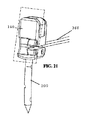
図25を参照すると、腹腔鏡下縫合器具10の遠位端部の分解組立て図が示されている。図示のように、遠位端部は、ジョー組立体100、ジョー作動機構体150、および細長いシャフト50の遠位端部52を有する。図示の実施形態では、ジョー組立体は、互いに回動可能に結合されるとともに実質的に類似している第1のジョー110と第2のジョー160を含む。本明細書において説明する縫合器具で使用可能なジョー組立体の他の実施形態では、縫合器具が互いに異なる形態を有するジョーを有しても良いことが想定される。例えば、ジョー組立体は、単一の回動可能なジョーおよび単一の静止ジョーもしくは回動可能なフリップジョーを備えた1つだけのジョーを含むことができる。かくして、幾つかの実施形態では、ジョー組立体は、第1のベースジョーおよび第1のベースジョーに回動可能に結合された第1のフリップジョーを有する第1のジョーと、細長いシャフトの遠位端部に回動可能に結合されているが、対応の第2のフリップジョーが設けられていない状態の針凹部を有する第2のジョーとを含むのが良い。他の実施形態では、第2のジョーは、細長いシャフトから長手方向遠位側に延びるのが良く、そして細長いシャフトに対して回動可能に固定されるのが良い。
With reference to FIG. 25, an exploded assembly view of the distal end of the
引き続き図25を参照すると、ジョー作動機構体150は、クレビス152およびアクチュエータ154を含むのが良い。クレビス152は、腰折れを阻止するためにシムおよびケーブルのためのガイドスロットを有するのが良い。アクチュエータ154のスロット付きヘッドがシムおよびケーブルを下側から支持してクレビス内における腰折れを阻止することができる。クレビスは、細長いシャフト50の遠位端部52のところに形成されるのが良くまたはこの遠位端部上に位置決めされるのが良い。第1および第2のジョーは、クレビス152に回動可能に結合されるのが良い。アクチュエータ154のスロット付きヘッドには作動スロット156が形成されるのが良い。図示の実施形態では、駆動ロッド158が細長いシャフト50内で摺動可能であり、この駆動ロッドは、アクチュエータ154を細長いシャフト50に対して近位側に前進させたり遠位側に前進させたりするようアクチュエータ154に結合されている。第1および第2のベースジョー120,170の作動ポスト126は、アクチュエータ154の長手方向並進によりベースジョー120,170が開閉されるよう作動スロット156内に位置決めされるのが良い。
Continuing with reference to FIG. 25, the
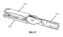
図26および図27は、アクチュエータ154、第1のベースジョー120、および第2のベースジョー170を示している。図示のように、アクチュエータ154を長手方向に並進させてベースジョー120,170を互いに対して回動させることができ、その結果、ベースジョー120,170を選択的に開き形態(図26)または閉じ形態(図27)に位置決めすることができるようになっている。
26 and 27 show the
図28および図29を参照すると、縫合針の実施形態が示されている。図示のように、針200は、第1の穿通先端部に隣接して位置する第1のシム切欠き210、第2の穿通先端部に隣接して位置する第2のシム切欠き212、第1の穿通先端部に隣接して位置する第1の凹部214、および第2の穿通先端部に隣接して位置する第2の凹部216を有する。どのシムが針をロックするかを交互に選択することによって、針をこの器具の2つのジョー相互間に通すことができる。有利には、針は、第1および第2の凹部214,216によって提供される戻り止め特徴部を更に有し、かかる戻り止め特徴部により、ジョーは、針を定位置に(すなわち、格納形態に)ロックするシムが存在していない状態で針を把持することができる。針は、縫合糸を挿通状態で受け入れる孔218を更に有するのが良い。想定されるように、幾つかの実施形態では、縫合糸は、孔218のところで針200に結合されたリーダーセグメント、例えば編組金属またはポリマーセグメントと、例えばクリンプ継手のところでこのリーダーに結合された縫合セグメントとを有するのが良い。種々の実施形態では、リーダーセグメントに結び目を作ることができ、リーダーセグメントを接着剤、熱成形によりくっつけることができ、あるいは針の周りに結束することができる。種々の実施形態では、縫合糸とリーダーに結び目を作ることにより、縫合糸およびリーダーを内部で熱成形することによって、または接着剤でくっつけることによってリーダーセグメントおよび縫合セグメントを固定することができる。縫合セグメントは、モノフィラメントポリマー縫合糸であるのが良い。
With reference to FIGS. 28 and 29, embodiments of suture needles are shown. As shown in the figure, the
望ましくは、編組リーダーおよびモノフィラメント縫合セグメントを備えたこの縫合糸構造は、弾性であるのが良く、しかも利用性を高めることができる。針を組織中に刺入することにより、針/リーダーインターフェースのところでのリーダーの曲げの繰り返しを生じさせることができる。より可撓性の高い材料をこのインターフェースのところでの材料の曲げの繰り返しに起因して破断する恐れを減少させることができる。この可撓性はまた、針を組織中に刺入する力の大きさを減少させ、と言うのは、この材料は、容易に曲がり、したがってプロフィールを減少させるからである。幾つかの実施形態では、リーダーを針孔中に挿入することができ、次にこの孔内に圧着させることができる。リーダーをステンレス鋼圧着管によって縫合糸に連結するのが良い。縫合糸はまた、可撓性を増大させるよう編組されるのが良い。幾つかの実施形態では、リーダーは、望ましくは強度を高めることができ、しかも針への溶接を可能にする編組ステンレス鋼であるのが良い。 Desirably, this suture structure with a braided leader and a monofilament suture segment should be elastic and can be more useful. Inserting the needle into the tissue can result in repeated bending of the leader at the needle / leader interface. The risk of breaking a more flexible material due to repeated bending of the material at this interface can be reduced. This flexibility also reduces the magnitude of the force with which the needle is inserted into the tissue, because the material bends easily and thus reduces the profile. In some embodiments, the leader can be inserted into the needle hole and then crimped into the hole. It is good to connect the leader to the suture with a stainless steel crimp tube. The sutures should also be braided to increase flexibility. In some embodiments, the leader is preferably braided stainless steel, which is preferably capable of increasing strength and yet allows welding to the needle.
幾つかの実施形態では、縫合セグメントは、これが組織を通って引っ込んで創傷の披裂を生じさせないように一方向にとげ付きのモノフィラメントまたは編組縫合糸から成るのが良い。この保持特徴部により、外科医がステッチの実施後のたびに結び目を作る必要性がなくなり、それにより手術の効率および容易さが向上する。針と反対側の縫合糸の端部は、組織中へのそれ以上の移動および創傷の披裂を阻止するためのアンカーを有するのが良い。幾つかの実施形態では、アンカーは、組織を通る最初のパス後に縫合糸を通す固定または可変直径ループを有するのが良く、その結果、結び目なしの固着部が得られる。次に、縫合は、結び目を全く作る必要なく続行される。他の実施形態では、縫合糸のアンカーは、T字形アンカーから成るのが良い。望ましくは、T字形アンカーは、組織を最初のパス後に縫合糸をアンカーループ中に通す必要をなくすことができる。 In some embodiments, the suture segment is preferably composed of a monofilament or braided suture that is barbed in one direction so that it does not retract through the tissue and cause wound tearing. This retention feature eliminates the need for the surgeon to tie a knot after each stitch, which improves the efficiency and ease of surgery. The end of the suture opposite the needle should have an anchor to prevent further movement into the tissue and tearing of the wound. In some embodiments, the anchor is preferably provided with a fixed or variable diameter loop through which the suture is passed after the first pass through the tissue, resulting in a knotless anchorage. The suture is then continued without the need to tie any knots. In other embodiments, the suture anchor is preferably composed of a T-shaped anchor. Desirably, the T-shaped anchor can eliminate the need for sutures to pass through the anchor loop after the first pass of tissue.
引き続き図29を参照すると、図示の実施形態では、針は、穿通先端部が互いに反対側の端部に配置された状態の二重ヘッド型形態から成るのが良い。針の中央本体は、全体として湾曲しているのが良い。幾つかの実施形態では、針は、針からベースジョーのピボット中心線までの距離に等しい曲げ半径を有するよう湾曲している。この曲げ半径は、組織を通って針を案内するのを助けることができ、しかも組織の穿通中に針を曲げる場合のあるトルクの大きさを最小限に抑えることができる。他の実施形態では、針は、単一の穿通先端部が一端部に設けられた単一ヘッド型形態から成るのが良い。 Continuing with reference to FIG. 29, in the illustrated embodiment, the needle preferably comprises a double-headed form in which the penetrating tips are located at opposite ends. The central body of the needle should be curved as a whole. In some embodiments, the needle is curved to have a bend radius equal to the distance from the needle to the pivot centerline of the base jaw. This bend radius can help guide the needle through the tissue and minimize the amount of torque that may cause the needle to bend during tissue penetration. In other embodiments, the needle may consist of a single head type with a single penetrating tip at one end.
図30〜図33を参照すると、第1のベースジョー120(図30)の実施形態およびクレビス152の実施形態が示されている。図示のように、ベースジョー120,170とクレビス152の両方は、シムおよびケーブルの操作を容易にする通路、例えば長手方向スロットまたはチャネルを有するのが良い。
With reference to FIGS. 30 to 33, an embodiment of the first base jaw 120 (FIG. 30) and an embodiment of the
図34〜図37を参照すると、ジョー組立体100およびジョー作動機構体150は、ジョー組立体が、針200がジョーのうちの一方の中に位置した状態の格納形態にある状態で示されている。図37は、リーダー222、圧着部224、および縫合セグメント226を備えた縫合糸220が取り付けられている針200を示している。
With reference to FIGS. 34-37, the
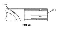
図38〜図40を参照すると、ジョー作動機構体のためのアクチュエータ154の一実施形態が示されている。図示のように、アクチュエータは、作動スロット156が互いに反対側の表面に設けられたスロット付き作動部材を有している。作動部材のスロット付き部分は、ピボットの近位側で第1のベースジョーと第2のベースジョーとの間に位置決めされるのが良く、その結果、ベースジョーの作動ポストが各々、作動スロット156内に受け入れられるようになっている。
With reference to FIGS. 38-40, one embodiment of the
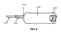
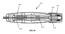
図41を参照すると、腹腔鏡下縫合器具10の実施形態が示されている。縫合器具10は、ハンドル組立体300、細長いシャフト50、およびジョー組立体100を有するのが良い。ハンドル組立体は、近位端部から遠位端部まで全体として長手方向に延びるのが良い。ハンドル組立体300は、ハンドル組立体から突き出た回動可能なレバーを含むトリガ機構体310を含むのが良い。他の実施形態では、他のハンドルおよびトリガ形態を本明細書において説明するジョー組立体機構体の種々の観点に使用することができることが想定される。細長いシャフト50は、ハンドル組立体の遠位端部から遠位側に延びるとともに縫合器具10の長手方向中心軸線を定めている。ジョー組立体100は、互いにかつ細長いシャフト50の遠位端部52に回動可能に結合された1対の対向したジョーを含むのが良い。
With reference to FIG. 41, an embodiment of the
図42および図43を参照すると、ハンドル組立体の実施形態が部分分解組立て図および完全分解組立て図で示されている。図42では、ハンドルハウジングは、ハンドルハウジング内に設けられているトリガ機構体310、クロージャ機構体340、トグル機構体350、およびラッチ機構体380を示すために取り外されている。図43では、トリガ機構体310、クロージャ機構体340、トグル機構体350、およびラッチ機構体380が分解組立て形態で示されている。
With reference to FIGS. 42 and 43, embodiments of the handle assembly are shown in partial fraction decomposition and fully disassembled assemblies. In FIG. 42, the handle housing has been removed to show the
図44および図45を参照すると、ハンドル組立体の実施形態の断面図が示されている。図44は、断面平面図である。図45は、断面側面図である。 With reference to FIGS. 44 and 45, cross-sectional views of embodiments of the handle assembly are shown. FIG. 44 is a cross-sectional plan view. FIG. 45 is a cross-sectional side view.
図46〜図51を参照すると、ハンドル組立体の部分断面図がジョー組立体100および針200の対応の位置とともに示されている。図46は、ハンドル組立体を針200が第1のジョー110内に位置決めされた初期位置で示している。図47および図48は、トリガ機構体の第1および第2のレバー312,322をハンドル組立体300のハンドル本体に向かって引き絞るときの作動順序を示している。図49〜図51は、トリガ機構体310の第1および第2のレバー312,322をハンドル組立体300のハンドル本体から解除しているときの作動順序を示している。
With reference to FIGS. 46-51, a partial cross-sectional view of the handle assembly is shown along with the corresponding positions of the
図46〜図48を参照すると、トリガ機構体は、各々がハンドル本体に対して回動可能な1対の対向したレバー312,322を含むのが良い。図示のように、レバーは、ハンドル組立体の遠位端部に隣接したところでハンドル本体に回動可能に結合されるのが良い。レバー312,322の各々には駆動スロット314,324が形成されるのが良い。図示のように、駆動スロット314,324は、レバーを引き絞っているときにジョーを当初閉じ、次にトグル機構体が作動されている間、レバー312,322のそれ以上の運動時に閉鎖状態を維持するよう構成されたプロフィールを有するのが良い。例えば、駆動スロット314,324は、駆動セグメント316,326および滞留セグメント318,328を有するのが良い。クロージャ機構体340が駆動スロット314,324によって案内されるとともに駆動ロッド342の近位端部に結合されたポストを含むのが良く、これらポストは、細長いシャフト50を貫通してジョー作動組立体150まで遠位側に延びている。したがって、ハンドル本体(図46および図47)に向かうレバー312,322の初期運動時、ポスト344は、駆動スロット314,324の駆動セグメント316,326を通って案内されて駆動ロッド342を長手方向に並進させてベースジョー120,170を閉じる(図47)。
With reference to FIGS. 46-48, the trigger mechanism preferably includes a pair of
図47および図48を参照すると、ハンドル本体に向かうレバー312,322のそれ以上の圧縮の結果として、クロージャ機構体のポスト344は、駆動スロット314,324の滞留セグメント318,328内で動き、その結果駆動ロッド342のそれ以上の変位が最小限に抑えられる。しかしながら、トリガ機構体のレバー312,322は各々、ハンドル組立体内で全体として近位側に延びる作動リンク320,330の第1の端部に回動可能に結合されている。第1の端部と反対側の作動リンク320,330の第2の端部は、ハンドル本体内で長手方向に並進可能な駆動プッシャ352に結合されている。ハンドル本体内における駆動プッシャ352の長手方向並進により、トグル機構体350を作動させることができ、それにより図52〜図60を参照して更に説明するようにトグル管354をハンドル本体内で選択的に回転させることができる。
With reference to FIGS. 47 and 48, as a result of further compression of the
図46〜図48を参照すると、トリガ機構体(図46および図47)のレバー312,322の初期圧縮により、作動リンク320,330が作動されて駆動プッシャ352をトグル機構体350のトグル管354に沿って近位側に並進させる。トリガ機構体のレバー312,322のそれ以上の圧縮により、作動リンク320,330が作動されて駆動プッシャをトグル管354に沿って近位側に並進させるとともにトグル管をハンドル本体の長手方向軸線回りに回転させる。図52〜図60を参照して本明細書において更に説明するように、トグル管354の回転により、第1のシム360および第2のシム370のうちの一方が交互に長手方向に送り進められて針200を第1および第2のジョーのうちの一方の中で交互に保持する。かくして、ユーザがトリガ機構体のレバー312,322を引き絞ると、ジョー組立体のジョーが閉じられ、針200が一方のジョーから別のジョーにわたされる。
With reference to FIGS. 46-48, the initial compression of the
図49〜図51を参照すると、レバー312,322を解除することにより、クロージャ機構体340のポスト344がスロット314,324(図49および図50)の滞留セグメント318,328に沿って案内される。この初期開放運動中、トグル管354は、引き続き回転し、シムのうちの一方の前進を完了させる。レバーが引き続き広がっているとき、クロージャ機構体340のポスト344は、スロット314,324(図50および図51)の駆動セグメント316,326沿いに動き、その結果、駆動ロッド342を長手方向に並進させてジョー組立体を開き形態に戻す。このそれ以上の運動により、駆動プッシャ352は、トグル機構体350のトグル管354に沿って遠位側に並進する。
With reference to FIGS. 49-51, by releasing the
図52〜図54を参照すると、トグル機構体の種々の観点がそれぞれ等角図、平面図、および側面図で示されている。図示のように、トグル機構体350は、トリガ機構体310の作動によってハンドル本体内で長手方向に摺動可能な駆動プッシャ352を含む。駆動プッシャ352は、駆動プッシャ352の各二股部から突き出たフォロワ353、例えばポストを有する二股状近位端部を有するのが良い。駆動プッシャ352が一体形成コンポーネントとして図示されているが、他の実施形態では、プッシャのフォークアームは、同様な仕方で機能する別々の部品であるのが良い。幾つかの実施形態では、プッシャのフォークアームは、剛性であるのが良く、ピンをトグル管と接触状態に保つ並進ピンおよびばね要素を備えるのが良い。トグル機構体350は、ハンドル本体内で回転可能なトグル管354を更に含むのが良い。図示のように、トグル管354は、カム駆動スロット356およびシムガイド358を有する。駆動プッシャのフォロワ353は、カム駆動スロット356内に位置決めされるのが良い。カム駆動スロット356は、1対の全体として長手方向に延びるリードセグメントおよびこれらリードセグメント相互間でハンドル本体の長手方向軸線に対して横向きの角度をなして延びる回転セグメントを有するのが良い。
With reference to FIGS. 52-54, various perspectives of the toggle mechanism are shown in isometric, plan and side views, respectively. As shown, the
引き続き図52〜図54を参照すると、トグル機構体350は、近位端部のところに第1のフォロワ362を備えた第1のシム360および近位端部のところに第2のフォロワ372を備えた第2のシム370を更に含むのが良い。フォロワ362,372は、シム360,370から半径方向内方に延びる突出ポストから成るのが良い。フォロワ362,372の各々は、トグル管354のシムガイド358内に位置決めされるのが良い。他の実施形態では、シムは、フォロワなしでシムを動かすためにシムガイド内に位置決めされた半径方向内方に延びるフランジを有するのが良い。シムガイド358は、シム前進プロフィールを有するのが良く、その結果、ハンドル本体内におけるトグル管354の回転により、シム360,370のフォロワ362,372が交互に長手方向に前進し、または引っ込むようになっている。かくして、トグルサイクルをなすトグル管354の回転により、シム360,370を交互に前進させたり引っ込めたりすることができ、それにより図18〜図20を参照して説明するように針をフリップジョーのうちの一方または他方の中に交互に保持することができるようになっている。
Continuing with reference to FIGS. 52-54, the
図55〜図60を参照すると、トグル機構体の作動順序が断面図で示されている。図55では、駆動プッシャ352のフォロワ353をカム駆動スロット356の長手方向リードセグメント内に位置決めし、第1のシム360が遠位側前進位置にあり、第2のシム370が引っ込み位置にある。図46および図47を参照して上述したようなジョー組立体の閉じに対応してトリガ機構体の当初の引き絞り操作中、フォロワ353を図55および図56に示されているようにカム駆動スロット356のリードセグメントに沿って長手方向近位側に前進させる。トグル管354をこの操作中回転させず、第1および第2のシム350,370は、これらの初期位置に位置したままである。
With reference to FIGS. 55 to 60, the operating order of the toggle mechanism is shown in cross-sectional view. In FIG. 55, the
図56〜図58を参照すると、トグル機構体350の作動順序中、いったんジョークロージャを越えてトリガ機構体を引き絞ると(図47および図48)、駆動プッシャ352のフォロワ353は、カム駆動スロット356の回転セグメントに達する。回転セグメントは、駆動プッシャ352による作動時、トグル管354を所定の方向に回転させるよう構成されているのが良い。例えば、回転セグメントは、回転セグメントとリードセグメントの交差部のところに可変深さプロフィールを有するのが良く、その結果、フォロワ353を回転セグメント中に前進させると、カムフォロワ353は、回転セグメントの所望のセグメントをたどってトグル管を所定の方向に回転させる傾向がある。回転セグメントは、ハンドル本体の長手方向軸線に対して横断方向のトグル管354に沿って延び、その結果、トグル管に対する駆動プッシャ352およびフォロワ353のそれ以上の近位側への前身により、トグル管354がハンドル本体内で回転するようになる(図56〜図58)。同様に、トグル管354のこの回転により、シムガイド358が回転し、その結果、第1のシムフォロワ362および第1のシム360が近位側に引っ込められ、第2のシムフォロワ372および第2のシム370は遠位側に送り進められる。かくして、図47および図48を参照して上述したようなジョー組立体の閉鎖したトリガ機構体の連続した引き絞り操作中、フォロワ353を図56〜図58に示されているようにカム駆動スロット356の回転セグメントに沿って前進させる。トグル管354をこの操作中回転させ、第1および第2のシム360,370を長手方向に動かす。
Referring to FIGS. 56-58, once the trigger mechanism is squeezed over the jaw closure during the operating sequence of the toggle mechanism 350 (FIGS. 47 and 48), the
図58〜図60を参照すると、トグル機構体350の作動シーケンス中、トリガ機構体をいったん完全引き絞り向きから解除すると(図49〜図51)、駆動プッシャ352のフォロワ353は、カム駆動スロット356の回転セグメントの最も近位側のピークに達する(図58)。回転セグメントは、トリガ機構体の解除および駆動プッシャ352の遠位側への運動時、トグル管354を所定の方向に回転させるのを続行するよう構成されているのが良い。例えば、回転セグメントは、回転セグメントの最も近位側のピークのところに可変深さプロフィールを有するのが良く、その結果、フォロワ353を回転セグメントに沿って前進させているとき、フォロワ353は、回転セグメントの所望のセグメントをたどる傾向があり、それによりトグル管を所定の方向に回転させるようになっている。さらに、フォロワ353を駆動プッシャに設けられている可撓性アームの端部のところに配置するのが良く、この可撓性アームは、フォロワ353が深さステップにわたって前進することができるようにする板ばねとして作用する。回転セグメントは、ハンドル本体の長手方向軸線に対して横断方向のトグル管354に沿って延び、その結果、トグル管に対する駆動プッシャ352およびフォロワ353の当初の遠位側への引っ込みにより、トグル管354は、ハンドル本体内で引き続き回転するようになる(図58および図59)。有利には、この回転の続行は、トグル管の「二重作用」ストローク(すなわち、トリガ機構体の引き絞りと解除の両方の間の回転)によって形成される。この二重作用ストロークは、望ましくは、もしそのように構成されていなければトグル管を回転させるのに必要なトリガ機構体のストローク長さを半分にし、それによりフォロワ353とカム駆動スロット356から成るシステムの小さな圧力角度の実現を可能にする。同様に、トグル管354のこの回転により、シムガイド358が回転し、その結果、第1のシムフォロワ362および第1のシム360が近位側に引っ込められ、第2のシムフォロワ372および第2のシム370が遠位側に送り進められる。かくして、図49および図50を参照して上述したように初期滞留部分に対応したトリガ機構体の当初の解除操作中、フォロワ353を図58および図59に示されているようにカム駆動スロット356の回転セグメントに沿って前進させる。トグル管354をこの操作中回転させ、第1および第2のシム360,370は、第2のシム370が遠位前進位置に達するとともに第1のシムが近位側引っ込み位置に達するまで遠位側に動き続ける。
Referring to FIGS. 58 to 60, once the trigger mechanism is released from the fully drawn throttle direction during the operation sequence of the toggle mechanism 350 (FIGS. 49 to 51), the
図60を参照すると、トグル機構体350の作動シーケンス中トリガ機構体が完全解除位置(図50および図51)まで移動し続けているとき、駆動プッシャ352のフォロワ353は、カム駆動スロット356の長手方向リードセグメントに達する(図60)。回転セグメントは、回転セグメントとリードセグメントの交差部のところに可変深さプロフィールを有するのが良く、その結果、フォロワ353を近位側に引っ込めているとき、フォロワ353は、リードセグメントに入る傾向がある。かくして、長手方向に延びるリードセグメントに沿うトグル管に対する駆動プッシャ352およびフォロワ353の遠位側への引っ込みの続行により、ハンドル本体内のトグル管354の回転向きが維持される(図60)。かくして、図50および図51を参照して上述したようなジョー開き部分に対応したトリガ機構体の完全解除作動中、フォロワ353を図60に示されているようにカム駆動スロット356のリードセグメントに沿って前進させる。この作動中、第2のシム370は、遠位側前進位置に位置したままであり、第1のシム360は、近位側引っ込み位置に位置したままである。
Referring to FIG. 60, when the trigger mechanism continues to move to the fully released position (FIGS. 50 and 51) during the activation sequence of the
したがって、図示の実施形態では、トリガ機構体の1回の圧縮および解除サイクルにより、トグル機構体350がサイクル動作してトグル管354を180°回転させる。トグル管354のこの180°の回転により、一方のシム360が遠位側前進位置から近位側引っ込み位置に再位置決めされるとともに他方のシム370が近位側引っ込み位置から遠位側前進位置に再位置決めされる。かくして、有利には、図示のトグル機構体により、単一のトリガ機構体がジョーの開き/閉じ/開きサイクルを作動させるとともにシムを交互に前進させて針をジョーのうちの一方の中に保持することができる。他の実施形態では、他のトグル機構体を用いると、トリガ機構体のサイクルに応動してシムを交互に前進させたり引っ込めたりすることができる。
Therefore, in the illustrated embodiment, one compression and decompression cycle of the trigger mechanism causes the
上述したように、フリップジョーは、格納形態と縫合形態の間で回転可能にねじりばね・ケーブル機構体を利用する。フリップジョーは、ベースジョーによってフリップジョーのいずれか一方の端部上に保持された合わせピン回りに回転する。幾つかの実施形態では、ケーブルの遠位端部は、対応のフリップジョーの底部に溶接されており、このケーブルの遠位端部は、ハンドル内に設けられたラッチ機構体によって制御される。他の実施形態では、ケーブルは、各ケーブルを対応のフリップジョーに設けられたスロット内に圧着することによりまたは対応のフリップジョーに取り付けられている各ケーブルの端部に取り付け具を設けることによって対応のフリップジョーに取り付けられるのが良い。他の実施形態では、フリップジョーケーブルもまた、はんだまたはろう付けによってフリップジョーに固定されるのが良い。ねじりばねは、フリップジョーとベースジョーとの間でフリップジョーの回転軸線上に位置している。ばねは、フリップジョーを回転させてこれを作動縫合形態にするよう付勢されている。フリップジョーを回転させてこれを作動状態にするため、ケーブルの張力が解除され、それによりねじりばねがジョーをくるっと回すことができる。フリップジョーを回転させてこれを非作動状態にするため、ケーブルに張力を加える。 As mentioned above, the flip jaws utilize a torsion spring cable mechanism that is rotatable between the retracted and sutured forms. The flip jaw rotates around a mating pin held by the base jaw on one end of the flip jaw. In some embodiments, the distal end of the cable is welded to the bottom of the corresponding flip jaw, and the distal end of the cable is controlled by a latch mechanism provided within the handle. In other embodiments, the cables are accommodated by crimping each cable into a slot provided in the corresponding flip jaw or by providing a fitting at the end of each cable attached to the corresponding flip jaw. It is good to attach it to the flip jaw. In other embodiments, the flip jaw cable may also be secured to the flip jaw by soldering or brazing. The torsion spring is located between the flip jaw and the base jaw on the axis of rotation of the flip jaw. The spring is urged to rotate the flip jaw into a working suture form. The flip jaws are rotated to bring them into operation, which releases the tension in the cable, which allows the torsion spring to spin the jaws. Tension the cable to rotate the flip jaw and deactivate it.
図61〜図63を参照すると、ラッチ機構体380の作動順序が示されている。図61は、ラッチ機構体をフリップジョーの縫合形態に対応したラッチ外し形態で示している。ラッチ機構体380は、ハンドル組立体の近位端部のところにラッチノブ381を含むのが良い。図示の実施形態では、ラッチノブ381は、第1および第2のガイドスロット384,386が形成されたラッチ管382に結合されている。ラッチ機構体は、図14〜図17を参照して上述したようにハンドル組立体および細長いシャフトを遠位側に貫通してジョー組立体のフリップジョーに結合された第1および第2のケーブル390,394を更に含む。ケーブル390,394の近位端部は、ラッチ管382のガイドスロット384,386内に位置決めされたポスト392,396に結合されている。ポスト392,396は、トグル機構体のトグル管354に結合されている支承管から突き出た合わせピンであるのが良く、ポスト392,396の近位側への運動によりトグル管およびシム360,370が近位側に引っ込められるようになっている。
With reference to FIGS. 61 to 63, the operation order of the
引き続き図61〜図63を参照すると、ラッチノブ381の回転時、ラッチ管382はこれに対応して回転する。かくして、ポスト392,396は、ガイド管のガイドスロット384,386との相互作用によって近位側に引っ込められる。ポスト392,396のこの近位側への運動により、張力がケーブル390,394に加えられてフリップジョーを縫合形態(図61)から格納形態(図63)に回動させる。また、ポスト392,396のこの近位側への運動により、トグル管354およびシム360,370が近位側に引っ込められる。ラッチ機構体380を部分的に回転させた状態で、シム360,370を両方のジョーから引っ込めるのが良く、その結果、ジョー組立体に所望ならば新たな針を再び装填することができるようになっている。ラッチノブ381のそれ以上の回転により、ポスト392,396は、例えば平坦なセグメントまたは戻り止めにより格納形態にあるフリップジョーを有するラッチ留め形態にラッチ機構体380を維持するよう構成されているのが良い案内スロット384,386の端部のところに位置決めされる。
With reference to FIGS. 61 to 63, when the
縫合器具をラッチ外ししてフリップジョーを縫合形態に位置決めすることが望まれる場合、図61〜図63の順序を逆に実施するのが良い。ラッチ外し順序では、ハンドル内のラッチ機構体は、ケーブル張力を解除するとともに針ロックシムを一動作で前方に摺動させる。ケーブル張力を解除するとともにばねが作動状態のフリップジョーの回転をやめた後、シムは、フリップジョー中に前方に摺動してフリップジョーが非作動状態に回転して戻るのを阻止する。一方のシムは、針をそのジョー内にロックするために更に摺動する。幾つかの実施形態では、ラッチ機構体は、縫合器具のラッチ留め形態とラッチ外し形態の両方においてケーブルに働く張力を維持するための引っ張りばねを更に含むのが良い。 When it is desired to unlatch the suturing device and position the flip jaw in the sutured form, it is preferable to reverse the order of FIGS. 61-63. In the unlatch order, the latch mechanism in the handle releases the cable tension and slides the needle lock shim forward in one action. After releasing the cable tension and stopping the spring from rotating the active flip jaw, the shim slides forward during the flip jaw to prevent the flip jaw from rotating back into the inactive state. One shim slides further to lock the needle into its jaw. In some embodiments, the latching mechanism may further include a tension spring to maintain tension acting on the cable in both the latched and unlatched forms of the suturing device.
ラッチ留め機構体のねじりばね付勢ラッチ外しおよびケーブル駆動ラッチ留め操作が図示されているが、他の実施形態では、他のラッチ留め機構体を本明細書において説明したような縫合器具に用いることができる。例えば、幾つかの実施形態では、各ジョーは、フリップジョーを縫合形態に回動させるための第1のケーブルおよびフリップジョーを格納形態に回動させるための第2のケーブルを有するのが良い。他の実施形態では、フリップジョーを押したり引いたりすることができるより剛性の高いケーブルまたはロッドを用いて縫合または格納形態に回転させまたは押すことができ、この場合、ねじりばねまたは2本の相互に反作用するケーブルの必要性がなくなる。さらに別の実施形態では、フリップジョーをウォーム歯車およびセクタ、ニチノールアクチュエータ、または親ねじ・ナット装置によってベースジョーに対して回動させるのが良い。 Torsion spring-loaded latching operations and cable-driven latching operations of the latching mechanism are illustrated, but in other embodiments, other latching mechanisms are used in suturing instruments as described herein. Can be done. For example, in some embodiments, each jaw may have a first cable for rotating the flip jaw into a sutured form and a second cable for rotating the flip jaw into a retracted form. In other embodiments, a stiffer cable or rod capable of pushing or pulling the flip jaws can be used to rotate or push into a sutured or retracted form, in which case a torsion spring or two mutuals. Eliminates the need for cables that react to. In yet another embodiment, the flip jaws may be rotated relative to the base jaws by a worm gear and sector, a Nitinol actuator, or a lead screw / nut device.
図64を参照すると、遠位端部に隣接した細長いシャフトの断面が示されている。図示の実施形態では、細長いシャフト50は、駆動ロッド、ケーブル、およびシムを挿通させるカバー管およびスペーサ部材56を有するのが良い。幾つかの実施形態では、スペーサ部材は、押し出し成形部材であるのが良い。スペーサ部材は、カバー管内のシム、ケーブル、および駆動ロッドの腰折れを阻止することができる。ユーザがトリガ機構体のレバーを引き絞ると、レバーは、縫合器具のシャフトの長さ沿いに下方へ駆動ロッドに力を伝達する。
With reference to FIG. 64, a cross section of an elongated shaft adjacent to the distal end is shown. In the illustrated embodiment, the
図65および図66を参照すると、幾つかの実施形態では、針200および縫合糸420は、編組ポリマー管アンカー430を有するのが良い。編組ポリマー管430は、縫合糸のためのアンカーとして使用できるよう針と反対側の縫合糸の端部のところに配置されるのが良い。編組ポリマー管430のアンカーは、溶接、接着剤、または別の接合方法により縫合糸の端部に取り付けられるのが良い。有利には、編組ポリマー管430は、多数の挿入領域が互いにオーバーラップしたポリマーストランドの隣り合う領域相互間の空所によって提供された状態で、外科医が針を通すための比較的容易な標的を提供することができる。
With reference to FIGS. 65 and 66, in some embodiments, the
図66を参照すると、ある特定の実施形態では、針200および縫合糸420は、針200と縫合糸420との間に編組ポリマー管を有するリーダーセグメント440を有するのが良い。編組ポリマー管は、針インターフェースのところに縫合糸の高められた可撓性を実現できる。
With reference to FIG. 66, in certain embodiments, the
図65および図66を参照すると、ある特定の実施形態では、針および縫合糸420は、縫合糸による組織の保持を容易にするよう一方向とげ付き(バーブド)縫合糸を含むのが良い。他の実施形態では、滑らかなモノフィラメント縫合糸を編組ポリマー管アンカーおよび/または編組ポリマー管リーダーと併用するのが良い。
With reference to FIGS. 65 and 66, in certain embodiments, the needle and
本明細書において説明する縫合器具は、これらの構成にあたって種々の材料および材料の組み合わせを有することができる。例えば、幾つかの実施形態では、フリップジョー、ベースジョー、クレビス、スロット付きヘッド、駆動ロッド、ケーブル、ねじりばね、シム、合わせピン、針、戻り止めばね、戻り止めボール、カバー管、縫合糸圧着部、トグル管、およびリベットは、金属、例えばステンレス鋼、アルミニウム、チタン、タングステン、黄銅、青銅、またはこれらの合金で作られるのが良い。幾つかの実施形態では、シムおよび/またはケーブルは、高い可撓性および長い疲れ寿命の実現を可能にするためにニッケル‐チタン(ニチノール)で作られるのが良い。幾つかの実施形態では、モノフィラメントまたは編組縫合糸および柔軟性マルチフィラメントリーダーは、非生体吸収性ポリマー、例えばポリプロピレン、ナイロン、ポリエステル、もしくは絹で作られても良く、あるいは、生体吸収性ポリマー、例えばポリジオキサノン、ポリ乳酸、ポリグリコリド、乳酸‐グリコール酸共重合体、ポリカプロラクトン、またはカットグットで作られても良い。幾つかの実施形態では、トリガレバー、リンケージ、ラッチ、ノブ、シムフォロワ、および駆動ロッドアダプタのうちの幾つかまたは全ては、プラスチック、例えばポリカーボネート、ABS、ポリエチレン、ポリプロピレン、PEEK、ポリウレタン、PVC、アクリル樹脂、ナイロン、ポリスチレン、アセタール、炭素繊維、ポリイミド、またはポリエステルで作られるのが良い。 The suturing instruments described herein can have various materials and material combinations in these configurations. For example, in some embodiments, flip jaws, base jaws, clevis, slotted heads, drive rods, cables, torsion springs, shims, mating pins, needles, anti-return springs, anti-return balls, cover tubes, suture crimps. The parts, toggle tubes, and rivets are preferably made of metals such as stainless steel, aluminum, titanium, tungsten, brass, bronze, or alloys thereof. In some embodiments, the shims and / or cables are preferably made of nickel-titanium (Nitinol) to allow for high flexibility and long fatigue life. In some embodiments, the monofilament or braided suture and flexible multifilament reader may be made of a non-bioabsorbable polymer such as polypropylene, nylon, polyester, or silk, or a bioabsorbable polymer such as. It may be made of polydioxanone, polylactic acid, polyglycolide, lactic acid-glycolic acid copolymer, polycaprolactone, or catgut. In some embodiments, some or all of the trigger levers, linkages, latches, knobs, shim followers, and drive rod adapters are plastics such as polycarbonate, ABS, polyethylene, polypropylene, PEEK, polyurethane, PVC, acrylic resin. , Nylon, polystyrene, acetal, carbon fiber, polyethylene, or polyester.
縫合器具の図示の実施形態は、比較的小径の手術ポートを通る比較的大径の針の挿入を可能にする格納小径プロフィール形態にジョーを構成するためのラッチ留め機構体を有するが、縫合器具の他の実施形態では、他の形態が挿入を可能にする小径プロフィールを達成することができるということが想定される。例えば、幾つかの実施形態では、縫合器具は、入れ子式に縮むことができる針を有することができる。圧縮要素、例えばばねが針内に収容されるのが良く、かかる圧縮要素により、針の2つの半部が組織穿通よりも大きな力を受けると同心状に縮むことができる。ジョーの閉じは、ジョーからジョーへの針の通過のための1つの設定およびジョーのそれ以上の閉じを可能にするための別の設定によって選択的に制御でき、それにより針を低プロフィール状態に縮めて5mmトロカールを通る引っ込みを可能にする。 The illustrated embodiment of the suturing instrument has a latching mechanism for configuring the jaws in a retracted small diameter profile form that allows the insertion of a relatively large diameter needle through a relatively small diameter surgical port, while the suturing instrument. In other embodiments, it is envisioned that other embodiments can achieve a small diameter profile that allows insertion. For example, in some embodiments, the suturing device can have needles that can be nested. A compression element, such as a spring, is preferably housed within the needle, which allows the two halves of the needle to contract concentrically when subjected to a force greater than tissue penetration. Joe closure can be selectively controlled by one setting for the passage of the needle from jaw to jaw and another setting to allow further closure of the jaw, thereby putting the needle in a low profile state. Shrinks to allow retracting through a 5mm trocar.
図示の実施形態では、縫合糸は、ジョー組立体が手術ポートを通って挿入可能な低プロフィール格納形態にある状態で細長いシャフトに沿って位置決めされる。他の実施形態では、縫合器具のプロフィールを挿入可能に更に減少させるということが想定される。例えば、幾つかの実施形態では、細長いシャフトのクレビスおよび外側管には、縫合糸がトロカール中への挿入中に整列する軸方向溝が形成されるのが良く、それにより縫合器具の断面プロフィールを減少させる。他の実施形態では、縫合糸を、トロカール中への挿入中に2つのベースジョー内にコイル状に巻きまたは折り曲げるのが良く、その目的は、縫合器具の断面プロフィールを減少させることにある。ジョー組立体を格納状態にしてベースジョーをコイル状に巻かれたまたは折り曲げられた縫合糸周りに閉じるのが良い。次に、ベースジョーを体腔内に位置している間に開いて縫合糸を放すのが良い。他の実施形態では、縫合器具は、導入管を更に有するのが良く、縫合糸をトロカールに通して挿入できるようこの導入管内でコイル状に巻きまたは折り曲げることができる。この導入管は、望ましくは、トロカールを通る挿入中、縫合器具の断面プロフィールを減少させることができ、しかも大きなプロフィールの縫合糸アンカーの使用を可能にする。導入管は、ベースジョーが格納形態をなして完全に閉じられている間にベースジョーを覆うのが良い。別の器械、例えば外科用把持器が体腔内にいったん挿入されると、導入管をジョーから引き離すことができ、それにより縫合糸を体腔内に放す。次に、導入管を他の器械のトロカールを通って体腔からすぐに抜去するのが良い。 In the illustrated embodiment, the suture is positioned along the elongated shaft with the jaw assembly in a low profile retractable form that can be inserted through the surgical port. In other embodiments, it is envisioned that the profile of the suturing device is further reduced to be insertable. For example, in some embodiments, the clevis and outer tube of the elongated shaft are preferably formed with an axial groove in which the suture aligns during insertion into the trocar, thereby providing a cross-sectional profile of the suture device. Reduce. In other embodiments, the suture is preferably coiled or bent into two base jaws during insertion into the trocar, the purpose of which is to reduce the cross-sectional profile of the suture device. It is preferable to retract the jaw assembly and close the base jaw around the coiled or bent suture. Next, it is better to open the base jaw while it is located in the body cavity and release the suture. In other embodiments, the suture device may further have an introductory tube, which can be coiled or bent within the introductory tube so that the suture can be inserted through the trocar. This introduction tube can preferably reduce the cross-sectional profile of the suture device during insertion through the trocar, yet allows the use of suture anchors with a larger profile. The introduction tube should cover the base jaw while it is retracted and completely closed. Once another instrument, such as a surgical gripper, is inserted into the body cavity, the introduction tube can be pulled away from the jaw, thereby releasing the suture into the body cavity. The introduction tube should then be immediately removed from the body cavity through the trocar of another instrument.
本願は、ある特定の好ましい実施形態および実施例を開示しているが、当業者には理解されるように、本発明は、具体的に開示した実施形態を超えて他の変形実施形態および/または本発明の使用ならびに自明な改造例およびその均等例に及ぶ。さらに、本発明の種々の特徴は、単独でまたは明示的に上述した特徴以外の本発明の他の特徴と組み合わせて使用できる。かくして、本明細書に開示された本発明の範囲は、上述の特定の開示した実施形態によっては限定されず、以下の特許請求の範囲の公正な解釈によってのみ定められるべきであることが意図されている。 Although the present application discloses certain preferred embodiments and examples, as will be appreciated by those skilled in the art, the present invention goes beyond specifically disclosed embodiments and / or other modified embodiments. Or it extends to the use of the present invention and trivial modifications and equivalents thereof. In addition, the various features of the invention can be used alone or in combination with other features of the invention other than those explicitly described above. Thus, it is intended that the scope of the invention disclosed herein is not limited by the particular disclosed embodiments described above, but should be defined only by a fair interpretation of the following claims. ing.
Claims (13)
近位端部および遠位端部を備えたハンドル組立体を有し、
前記ハンドル組立体の前記遠位端部から遠位側に延びていて長手方向中心軸線を定める細長いシャフトを有し、
前記細長いシャフトから遠位側に延びるジョー組立体を有し、前記ジョー組立体は、各々が前記細長いシャフトに回動可能に結合された近位端部と、遠位端部とを備えた第1のジョーおよび第2のジョーを含み、
針を有し、
前記ジョー組立体および前記針は、前記針が前記第1のジョーおよび前記第2のジョーのうちの一方内に位置決めされるとともに、前記第1のジョー、前記第2のジョー、および前記針が前記長手方向中心軸線と全体として整列した格納形態と、前記第1のジョー、前記第2のジョー、および前記針が前記長手方向中心軸線に対して横断方向に延びる開き位置との間で選択的に位置決め可能であり、
前記第1のジョーは、
前記第1のジョーの前記近位端部のところに位置する第1のベースジョーと、
前記第1のジョーの前記遠位端部のところに位置していて前記第1のベースジョーに回動可能に結合された第1のフリップジョーと、を有し、前記第1のフリップジョーは、前記ジョー組立体が前記格納形態にある格納位置と縫合位置との間で前記第1のベースジョーに対して回動可能であり、
前記第2のジョーは、
前記第2のジョーの前記近位端部のところに位置する第2のベースジョーと、
前記第2のジョーの前記遠位端部のところに位置していて前記第2のベースジョーに回動可能に結合された第2のフリップジョーと、を有し、前記第2のフリップジョーは、前記ジョー組立体が前記格納形態にある格納位置と縫合位置との間で前記第2のベースジョーに対して回動可能である、
ことを特徴とする腹腔鏡下縫合器具。 Laparoscopic suture device
Has a handle assembly with proximal and distal ends,
It has an elongated shaft extending distally from the distal end of the handle assembly and defining a longitudinal central axis.
A third jaw assembly having a jaw assembly extending distally from the elongated shaft, each comprising a proximal end rotatably coupled to the elongated shaft and a distal end. Including 1 jaw and 2nd jaw
Has a needle,
In the jaw assembly and the needle, the needle is positioned within one of the first jaw and the second jaw, and the first jaw, the second jaw, and the needle Selective between a storage configuration that is aligned as a whole with the longitudinal central axis and an opening position where the first jaw, the second jaw, and the needle extend transversely to the longitudinal central axis. Can be positioned to
The first jaw is
With the first base jaw located at the proximal end of the first jaw,
The first flip jaw comprises a first flip jaw located at the distal end of the first jaw and rotatably coupled to the first base jaw. , The jaw assembly is rotatable with respect to the first base jaw between the retracted position and the stitched position in the retracted form.
The second jaw
With a second base jaw located at the proximal end of the second jaw,
The second flip jaw has a second flip jaw located at the distal end of the second jaw and rotatably coupled to the second base jaw. , The jaw assembly is rotatable with respect to the second base jaw between the storage position and the suture position in the storage form.
A laparoscopic suturing device characterized by this.
請求項1に記載の腹腔鏡下縫合器具。 The handle assembly includes a latch mechanism operably coupled to the jaw assembly to selectively position the first jaw and the second jaw into the retracted form.
The laparoscopic suturing device according to claim 1.
請求項1に記載の腹腔鏡下縫合器具。 A needle receiving channel is formed in the first flip jaw, and the needle receiving channel extends with respect to an axis extending from the proximal end of the first jaw to the distal end of the first jaw. Positioned in the transverse direction as a whole,
The laparoscopic suturing device according to claim 1.
請求項3に記載の腹腔鏡下縫合器具。 The first flip jaw is provided with a detent that engages the needle when a portion of the needle is positioned within the needle receiving channel.
The laparoscopic suturing device according to claim 3.
請求項3に記載の腹腔鏡下縫合器具。 A shim channel extends through the first flip jaw, and the shim channel crosses the needle receiving channel.
The laparoscopic suturing device according to claim 3.
請求項5に記載の腹腔鏡下縫合器具。 The first flip jaw can be partially extended into the shim channel to lock into the suture form, and when the needle is positioned within the needle receiving channel, it engages with the needle. Further having a shim capable of extending into the needle receiving channel,
The laparoscopic suturing device according to claim 5.
請求項6に記載の腹腔鏡下縫合器具。 The needle has a shim notch that aligns with the shim channel of the first flip jaw when the needle is positioned within the needle receiving channel of the first flip jaw.
The laparoscopic suturing device according to claim 6.
請求項1に記載の腹腔鏡下縫合器具。 The needle has a first penetration tip and a second penetration tip opposite the first penetration tip.
The laparoscopic suturing device according to claim 1.
近位端部および遠位端部を備えたハンドル組立体を有し、Has a handle assembly with proximal and distal ends,
前記ハンドル組立体の前記遠位端部から遠位側に延びていて長手方向中心軸線を定める細長いシャフトを有し、It has an elongated shaft extending distally from the distal end of the handle assembly and defining a longitudinal central axis.
前記細長いシャフトから遠位側に延びるジョー組立体を有し、前記ジョー組立体は、各々が前記細長いシャフトに回動可能に結合された近位端部と、遠位端部とを備えた第1のジョーおよび第2のジョーを含み、A third jaw assembly having a jaw assembly extending distally from the elongated shaft, each comprising a proximal end rotatably coupled to the elongated shaft and a distal end. Including 1 jaw and 2nd jaw
針を有し、Has a needle,
前記ジョー組立体および前記針は、前記針が前記第1のジョーおよび前記第2のジョーのうちの一方内に位置決めされるとともに、前記第1のジョー、前記第2のジョー、および前記針が前記長手方向中心軸線と全体として整列した格納形態と、前記第1のジョー、前記第2のジョー、および前記針が前記長手方向中心軸線に対して横断方向に延びる開き位置との間で選択的に位置決め可能であり、In the jaw assembly and the needle, the needle is positioned within one of the first jaw and the second jaw, and the first jaw, the second jaw, and the needle Selective between a storage configuration that is aligned as a whole with the longitudinal central axis and an opening position where the first jaw, the second jaw, and the needle extend transversely to the longitudinal central axis. Can be positioned to
前記第1のジョーは、The first jaw is
前記第1のジョーの前記近位端部のところに位置する第1のベースジョーと、With the first base jaw located at the proximal end of the first jaw,
前記第1のジョーの前記遠位端部のところに位置していて前記第1のベースジョーに回動可能に結合された第1のフリップジョーと、を有し、前記第1のフリップジョーは、前記ジョー組立体が前記格納形態にある格納位置と縫合位置との間で前記第1のベースジョーに対して回動可能であり、The first flip jaw comprises a first flip jaw located at the distal end of the first jaw and rotatably coupled to the first base jaw. , The jaw assembly is rotatable with respect to the first base jaw between the retracted position and the stitched position in the retracted form.
前記第1のフリップジョーには針受け入れチャネルが形成され、前記針受け入れチャネルは、前記第1のフリップジョーが縫合位置にあるとき、前記第1のジョーの前記近位端部から前記第1のジョーの前記遠位端部まで延びる軸線に対して全体として横断方向に位置決めされ、A needle receiving channel is formed in the first flip jaw, and the needle receiving channel is the first from the proximal end of the first jaw when the first flip jaw is in the suture position. Positioned as a whole in the transverse direction with respect to the axis extending to the distal end of the jaw.
前記第1のフリップジョーを貫通してシムチャネルが延び、前記シムチャネルは、前記針受け入れチャネルを横切り、A shim channel extends through the first flip jaw, and the shim channel crosses the needle receiving channel.
前記第1のフリップジョーを前記縫合形態にロックするよう前記シムチャネル中に部分的に伸長することができ、更に前記針が前記針受け入れチャネル内に位置決めされると、前記針に係合するよう前記針受け入れチャネル中に伸長することができるシムを更に有する、The first flip jaw can be partially extended into the shim channel to lock into the suture form, and when the needle is positioned within the needle receiving channel, it engages with the needle. Further having a shim capable of extending into the needle receiving channel,
ことを特徴とする腹腔鏡下縫合器具。A laparoscopic suturing device characterized by this.
請求項9に記載の腹腔鏡下縫合器具。The laparoscopic suturing device according to claim 9.
請求項9に記載の腹腔鏡下縫合器具。The laparoscopic suturing device according to claim 9.
請求項9に記載の腹腔鏡下縫合器具。The laparoscopic suturing device according to claim 9.
請求項9に記載の腹腔鏡下縫合器具。The laparoscopic suturing device according to claim 9.
Priority Applications (2)
| Application Number | Priority Date | Filing Date | Title |
|---|---|---|---|
| JP2021043168A JP7177202B2 (en) | 2015-09-11 | 2021-03-17 | Laparoscopic suture system |
| JP2022180228A JP7454628B2 (en) | 2015-09-11 | 2022-11-10 | Laparoscopic suturing system |
Applications Claiming Priority (3)
| Application Number | Priority Date | Filing Date | Title |
|---|---|---|---|
| US201562217502P | 2015-09-11 | 2015-09-11 | |
| US62/217,502 | 2015-09-11 | ||
| PCT/US2016/051089 WO2017044838A1 (en) | 2015-09-11 | 2016-09-09 | Laparoscopic suturing system |
Related Child Applications (1)
| Application Number | Title | Priority Date | Filing Date |
|---|---|---|---|
| JP2021043168A Division JP7177202B2 (en) | 2015-09-11 | 2021-03-17 | Laparoscopic suture system |
Publications (3)
| Publication Number | Publication Date |
|---|---|
| JP2018527097A JP2018527097A (en) | 2018-09-20 |
| JP2018527097A5 JP2018527097A5 (en) | 2019-10-10 |
| JP6855457B2 true JP6855457B2 (en) | 2021-04-07 |
Family
ID=56940464
Family Applications (3)
| Application Number | Title | Priority Date | Filing Date |
|---|---|---|---|
| JP2018512963A Active JP6855457B2 (en) | 2015-09-11 | 2016-09-09 | Laparoscopic suture system |
| JP2021043168A Active JP7177202B2 (en) | 2015-09-11 | 2021-03-17 | Laparoscopic suture system |
| JP2022180228A Active JP7454628B2 (en) | 2015-09-11 | 2022-11-10 | Laparoscopic suturing system |
Family Applications After (2)
| Application Number | Title | Priority Date | Filing Date |
|---|---|---|---|
| JP2021043168A Active JP7177202B2 (en) | 2015-09-11 | 2021-03-17 | Laparoscopic suture system |
| JP2022180228A Active JP7454628B2 (en) | 2015-09-11 | 2022-11-10 | Laparoscopic suturing system |
Country Status (8)
| Country | Link |
|---|---|
| US (3) | US10405851B2 (en) |
| EP (1) | EP3346927B1 (en) |
| JP (3) | JP6855457B2 (en) |
| KR (2) | KR102649259B1 (en) |
| AU (3) | AU2016321317B2 (en) |
| CA (1) | CA2998418A1 (en) |
| ES (1) | ES2788640T3 (en) |
| WO (1) | WO2017044838A1 (en) |
Families Citing this family (13)
| Publication number | Priority date | Publication date | Assignee | Title |
|---|---|---|---|---|
| WO2019117811A1 (en) * | 2017-12-12 | 2019-06-20 | Nanyang Technological University | Suturing end-effector |
| EP3749223A4 (en) * | 2018-03-23 | 2021-04-14 | Ege Universitesi | A single-impulse, semi-mobile and stoppered suturing device used in narrow and deep tissue planes surgery |
| KR20200140298A (en) * | 2018-03-30 | 2020-12-15 | 마루호 메디컬, 인크. | Method and apparatus for passing suture |
| SE543080C2 (en) | 2018-05-25 | 2020-10-06 | Suturion Ab | A suturing device with needle-transfer of a double-ended needle |
| US20210275167A1 (en) * | 2020-03-06 | 2021-09-09 | Hologic, Inc. | Vaginal cuff closure laparoscopic suture passer |
| US11751866B2 (en) * | 2020-04-24 | 2023-09-12 | Covidien Lp | Endoscopic stitching device having angled suture needle |
| JP2024514977A (en) * | 2021-04-26 | 2024-04-03 | ボストン サイエンティフィック サイムド,インコーポレイテッド | Suture-Based Closure Devices |
| WO2023278219A1 (en) * | 2021-07-02 | 2023-01-05 | Hologic, Inc. | Running stitch suturing instrument |
| CA3231742A1 (en) | 2021-09-07 | 2023-03-16 | Soranus Arge Ve Danismanlik Hizmetleri Sanayi Ticaret Anonim Sirketi | Suturing device and methods of use thereof |
| ES2947435A1 (en) * | 2022-02-07 | 2023-08-09 | Chairmonkey S L | Endoscopic thread suturing device (Machine-translation by Google Translate, not legally binding) |
| CN114504355B (en) * | 2022-02-14 | 2024-02-13 | 郭朝辉 | Auxiliary device for removing stone in hepatobiliary surgery |
| US11678874B1 (en) | 2022-10-26 | 2023-06-20 | King Faisal University | Double “J” laparoscopic fascial closure device |
| CN115737029B (en) * | 2023-01-10 | 2023-05-16 | 青岛智兴医疗器械有限公司 | Continuous stitching instrument |
Family Cites Families (54)
| Publication number | Priority date | Publication date | Assignee | Title |
|---|---|---|---|---|
| US2591063A (en) | 1949-05-14 | 1952-04-01 | Goldberg Harry | Surgical suture |
| US3311110A (en) | 1964-07-15 | 1967-03-28 | American Cyanamid Co | Flexible composite suture having a tandem linkage |
| US3842840A (en) * | 1973-05-07 | 1974-10-22 | E Schweizer | Suture applicator |
| US3963031A (en) * | 1974-12-11 | 1976-06-15 | Ethicon, Inc. | Juncture-lubricated needle-suture combination |
| JPH0382458A (en) * | 1989-08-28 | 1991-04-08 | Matsutani Seisakusho Co Ltd | Stitching needle with thread and method of processing stitching needle with thread |
| US5318577A (en) | 1990-06-26 | 1994-06-07 | Mitek Surgical Products, Inc. | Suture threading device |
| GB2260704B (en) | 1991-09-30 | 1995-08-23 | Philip Richardson | Suturing apparatus |
| US5330502A (en) * | 1992-10-09 | 1994-07-19 | Ethicon, Inc. | Rotational endoscopic mechanism with jointed drive mechanism |
| US5569301A (en) * | 1993-10-08 | 1996-10-29 | United States Surgical Corporation | Surgical incision members for endoscopic suturing apparatus |
| CA2133377C (en) | 1993-10-08 | 2004-09-14 | H. Jonathan Tovey | Surgical suturing apparatus with loading mechanism |
| US5674230A (en) | 1993-10-08 | 1997-10-07 | United States Surgical Corporation | Surgical suturing apparatus with locking mechanisms |
| US5478344A (en) | 1993-10-08 | 1995-12-26 | United States Surgical Corporation | Surgical suturing apparatus with loading mechanism |
| US5397325A (en) * | 1993-11-09 | 1995-03-14 | Badiaco, Inc. | Laparoscopic suturing device |
| US5431666A (en) | 1994-02-24 | 1995-07-11 | Lasersurge, Inc. | Surgical suture instrument |
| DE4423881C1 (en) * | 1994-07-07 | 1995-10-26 | Karlsruhe Forschzent | Surgical sewing device |
| US5478345A (en) | 1994-08-19 | 1995-12-26 | United States Surgical Corporation | Mechanism for endoscopic suturing device |
| US5480406A (en) | 1994-10-07 | 1996-01-02 | United States Surgical Corporation | Method of employing surgical suturing apparatus to tie knots |
| USD384413S (en) | 1994-10-07 | 1997-09-30 | United States Surgical Corporation | Endoscopic suturing instrument |
| US6056771A (en) | 1995-06-02 | 2000-05-02 | United States Surgical Corporation | Radiused tip surgical needles and surgical incision members |
| US5693071A (en) * | 1996-01-23 | 1997-12-02 | United States Surgical Corporation | Tapered surgical needles and surgical incision members |
| US5865836A (en) * | 1996-09-20 | 1999-02-02 | United States Surgical Corporation | Needle-suture combination |
| US5814054A (en) | 1996-09-23 | 1998-09-29 | Symbiosis Corporation | Automatic needle-passer suturing instrument |
| US5993467A (en) * | 1996-11-27 | 1999-11-30 | Yoon; Inbae | Suturing instrument with rotatably mounted spreadable needle holder |
| US5947982A (en) * | 1997-04-02 | 1999-09-07 | Smith & Nephew, Inc. | Suture-passing forceps |
| US5908428A (en) * | 1997-05-27 | 1999-06-01 | United States Surgical Corporation | Stitching devices for heart valve replacement surgery |
| US5895395A (en) | 1997-07-17 | 1999-04-20 | Yeung; Teresa T. | Partial to full thickness suture device & method for endoscopic surgeries |
| AT408832B (en) * | 1997-09-09 | 2002-03-25 | Werner Ing Fuchs | SURGICAL SEWING PLIERS |
| JP2000037391A (en) | 1998-07-24 | 2000-02-08 | Manii Kk | Guide implement of medical needle with thread |
| US20040122456A1 (en) * | 2002-12-11 | 2004-06-24 | Saadat Vahid C. | Methods and apparatus for gastric reduction |
| US6533795B1 (en) * | 2000-04-11 | 2003-03-18 | Opus Medical, Inc | Dual function suturing apparatus and method |
| US7037324B2 (en) * | 2000-09-15 | 2006-05-02 | United States Surgical Corporation | Knotless tissue anchor |
| DE60308707T2 (en) * | 2002-10-04 | 2007-08-09 | Tyco Healthcare Group Lp, Norwalk | MEASURING CONSTRUCTION FOR SURGICAL DEVICES |
| AU2005209239B2 (en) * | 2004-01-23 | 2010-12-09 | Ams Research Corporation | Tissue fastening and cutting tool, and methods |
| US8641729B2 (en) | 2005-07-13 | 2014-02-04 | Creighton University | Systems and techniques for minimally invasive gastrointestinal procedures |
| US8372090B2 (en) | 2006-10-05 | 2013-02-12 | Covidien Lp | Flexible endoscopic stitching devices |
| US8353931B2 (en) | 2006-11-02 | 2013-01-15 | Covidien Lp | Long term bioabsorbable barbed sutures |
| WO2009061504A1 (en) * | 2007-11-05 | 2009-05-14 | Revolutionary Surgical Device, Llc | Suture passing instrument and method |
| US8512362B2 (en) | 2007-11-05 | 2013-08-20 | Usgi Medical Inc. | Endoscopic ligation |
| US20100228270A1 (en) | 2008-04-11 | 2010-09-09 | Michael Bogart | Deployment System for Surgical Suture |
| US8864776B2 (en) * | 2008-04-11 | 2014-10-21 | Covidien Lp | Deployment system for surgical suture |
| US20110040308A1 (en) * | 2008-06-13 | 2011-02-17 | Ramiro Cabrera | Endoscopic Stitching Devices |
| US8628545B2 (en) * | 2008-06-13 | 2014-01-14 | Covidien Lp | Endoscopic stitching devices |
| US8517073B2 (en) | 2009-07-16 | 2013-08-27 | Covidien Lp | Apparatus and method for joining similar or dissimilar suture products |
| US8490713B2 (en) | 2009-10-06 | 2013-07-23 | Covidien Lp | Handle assembly for endoscopic suturing device |
| JP5894930B2 (en) | 2009-12-22 | 2016-03-30 | クック・メディカル・テクノロジーズ・リミテッド・ライアビリティ・カンパニーCook Medical Technologies Llc | Medical instrument and method for suturing tissue |
| AU2011249910A1 (en) * | 2010-05-06 | 2012-11-08 | Synthes Gmbh | Soft tissue defect device and associated method |
| US8398679B2 (en) | 2010-10-28 | 2013-03-19 | Covidien Lp | Modular suture |
| US8906043B2 (en) | 2010-11-15 | 2014-12-09 | Ethicon Endo-Surgery, Inc. | Laparoscopic suturing instrument with perpendicular eccentric needle motion |
| US8968339B2 (en) * | 2010-12-10 | 2015-03-03 | Covidien Lp | Suturing device with deployable needle |
| US20120253388A1 (en) | 2011-03-29 | 2012-10-04 | Tyco Healthcare Group Lp | Anchor Member For Looped Sutures |
| WO2013008817A1 (en) | 2011-07-11 | 2013-01-17 | オリンパスメディカルシステムズ株式会社 | Treatment system and endoscopic system |
| US9247936B2 (en) | 2012-09-20 | 2016-02-02 | Medos International Sarl | Suture leader |
| US9675340B2 (en) * | 2013-11-20 | 2017-06-13 | Covidien Lp | Stitching device with long needle |
| US9907550B2 (en) * | 2014-01-27 | 2018-03-06 | Covidien Lp | Stitching device with long needle delivery |
-
2016
- 2016-09-09 WO PCT/US2016/051089 patent/WO2017044838A1/en active Application Filing
- 2016-09-09 US US15/261,422 patent/US10405851B2/en active Active
- 2016-09-09 ES ES16766813T patent/ES2788640T3/en active Active
- 2016-09-09 JP JP2018512963A patent/JP6855457B2/en active Active
- 2016-09-09 CA CA2998418A patent/CA2998418A1/en active Pending
- 2016-09-09 AU AU2016321317A patent/AU2016321317B2/en active Active
- 2016-09-09 KR KR1020187010261A patent/KR102649259B1/en active Application Filing
- 2016-09-09 KR KR1020247008230A patent/KR20240037367A/en active Application Filing
- 2016-09-09 EP EP16766813.6A patent/EP3346927B1/en active Active
-
2019
- 2019-09-09 US US16/565,065 patent/US11406373B2/en active Active
-
2021
- 2021-03-17 JP JP2021043168A patent/JP7177202B2/en active Active
- 2021-03-23 AU AU2021201792A patent/AU2021201792B2/en active Active
-
2022
- 2022-06-30 US US17/854,632 patent/US20220323065A1/en active Pending
- 2022-11-10 JP JP2022180228A patent/JP7454628B2/en active Active
-
2023
- 2023-01-19 AU AU2023200266A patent/AU2023200266A1/en active Pending
Also Published As
| Publication number | Publication date |
|---|---|
| AU2021201792B2 (en) | 2022-10-20 |
| CA2998418A1 (en) | 2017-03-16 |
| WO2017044838A1 (en) | 2017-03-16 |
| US20200000457A1 (en) | 2020-01-02 |
| AU2016321317A1 (en) | 2018-04-05 |
| US20170071597A1 (en) | 2017-03-16 |
| KR20180053698A (en) | 2018-05-23 |
| EP3346927B1 (en) | 2020-02-19 |
| KR20240037367A (en) | 2024-03-21 |
| AU2023200266A1 (en) | 2023-02-16 |
| JP2021106882A (en) | 2021-07-29 |
| US10405851B2 (en) | 2019-09-10 |
| JP7454628B2 (en) | 2024-03-22 |
| US11406373B2 (en) | 2022-08-09 |
| AU2016321317B2 (en) | 2020-12-24 |
| EP3346927A1 (en) | 2018-07-18 |
| JP2023025030A (en) | 2023-02-21 |
| US20220323065A1 (en) | 2022-10-13 |
| JP2018527097A (en) | 2018-09-20 |
| AU2021201792A1 (en) | 2021-04-15 |
| KR102649259B1 (en) | 2024-03-20 |
| JP7177202B2 (en) | 2022-11-22 |
| ES2788640T3 (en) | 2020-10-22 |
Similar Documents
| Publication | Publication Date | Title |
|---|---|---|
| JP7177202B2 (en) | Laparoscopic suture system | |
| US11779326B2 (en) | Stitching device with long needle | |
| US11045341B2 (en) | Apparatus for manipulating and securing tissue | |
| US7621925B2 (en) | Needle assembly for tissue manipulation | |
| EP1804680B1 (en) | Apparatus for manipulating and securing tissue | |
| US7347863B2 (en) | Apparatus and methods for manipulating and securing tissue | |
| US20090326578A1 (en) | Interlocking tissue anchor apparatus and methods |
Legal Events
| Date | Code | Title | Description |
|---|---|---|---|
| A521 | Request for written amendment filed |
Free format text: JAPANESE INTERMEDIATE CODE: A523 Effective date: 20190828 |
|
| A621 | Written request for application examination |
Free format text: JAPANESE INTERMEDIATE CODE: A621 Effective date: 20190828 |
|
| A131 | Notification of reasons for refusal |
Free format text: JAPANESE INTERMEDIATE CODE: A131 Effective date: 20200910 |
|
| A977 | Report on retrieval |
Free format text: JAPANESE INTERMEDIATE CODE: A971007 Effective date: 20200911 |
|
| A521 | Request for written amendment filed |
Free format text: JAPANESE INTERMEDIATE CODE: A523 Effective date: 20201209 |
|
| TRDD | Decision of grant or rejection written | ||
| A01 | Written decision to grant a patent or to grant a registration (utility model) |
Free format text: JAPANESE INTERMEDIATE CODE: A01 Effective date: 20210215 |
|
| A61 | First payment of annual fees (during grant procedure) |
Free format text: JAPANESE INTERMEDIATE CODE: A61 Effective date: 20210317 |
|
| R150 | Certificate of patent or registration of utility model |
Ref document number: 6855457 Country of ref document: JP Free format text: JAPANESE INTERMEDIATE CODE: R150 |
|
| R250 | Receipt of annual fees |
Free format text: JAPANESE INTERMEDIATE CODE: R250 |