EP3346927B1 - Laparoscopic suturing system - Google Patents
Laparoscopic suturing system Download PDFInfo
- Publication number
- EP3346927B1 EP3346927B1 EP16766813.6A EP16766813A EP3346927B1 EP 3346927 B1 EP3346927 B1 EP 3346927B1 EP 16766813 A EP16766813 A EP 16766813A EP 3346927 B1 EP3346927 B1 EP 3346927B1
- Authority
- EP
- European Patent Office
- Prior art keywords
- jaw
- needle
- flip
- assembly
- shim
- Prior art date
- Legal status (The legal status is an assumption and is not a legal conclusion. Google has not performed a legal analysis and makes no representation as to the accuracy of the status listed.)
- Active
Links
- 230000007246 mechanism Effects 0.000 claims description 95
- 230000000149 penetrating effect Effects 0.000 claims description 9
- 238000003780 insertion Methods 0.000 description 12
- 230000037431 insertion Effects 0.000 description 12
- 229920000642 polymer Polymers 0.000 description 9
- 239000000463 material Substances 0.000 description 5
- 230000006835 compression Effects 0.000 description 4
- 238000007906 compression Methods 0.000 description 4
- 230000014759 maintenance of location Effects 0.000 description 4
- 239000000853 adhesive Substances 0.000 description 3
- 230000001070 adhesive effect Effects 0.000 description 3
- 229910001000 nickel titanium Inorganic materials 0.000 description 3
- -1 polypropylene Polymers 0.000 description 3
- 125000006850 spacer group Chemical group 0.000 description 3
- 229910001220 stainless steel Inorganic materials 0.000 description 3
- 239000010935 stainless steel Substances 0.000 description 3
- 239000004677 Nylon Substances 0.000 description 2
- 239000004743 Polypropylene Substances 0.000 description 2
- 206010048031 Wound dehiscence Diseases 0.000 description 2
- 230000009471 action Effects 0.000 description 2
- 238000005452 bending Methods 0.000 description 2
- 230000008901 benefit Effects 0.000 description 2
- 238000010276 construction Methods 0.000 description 2
- 238000000034 method Methods 0.000 description 2
- HLXZNVUGXRDIFK-UHFFFAOYSA-N nickel titanium Chemical compound [Ti].[Ti].[Ti].[Ti].[Ti].[Ti].[Ti].[Ti].[Ti].[Ti].[Ti].[Ni].[Ni].[Ni].[Ni].[Ni].[Ni].[Ni].[Ni].[Ni].[Ni].[Ni].[Ni].[Ni].[Ni] HLXZNVUGXRDIFK-UHFFFAOYSA-N 0.000 description 2
- 229920001778 nylon Polymers 0.000 description 2
- 229920000728 polyester Polymers 0.000 description 2
- 229920001155 polypropylene Polymers 0.000 description 2
- 238000001356 surgical procedure Methods 0.000 description 2
- 238000003466 welding Methods 0.000 description 2
- 229910001369 Brass Inorganic materials 0.000 description 1
- 229910000906 Bronze Inorganic materials 0.000 description 1
- 229920000049 Carbon (fiber) Polymers 0.000 description 1
- AEMRFAOFKBGASW-UHFFFAOYSA-N Glycolic acid Polymers OCC(O)=O AEMRFAOFKBGASW-UHFFFAOYSA-N 0.000 description 1
- 239000004696 Poly ether ether ketone Substances 0.000 description 1
- 239000004698 Polyethylene Substances 0.000 description 1
- 229920000954 Polyglycolide Polymers 0.000 description 1
- 239000004642 Polyimide Substances 0.000 description 1
- 239000004793 Polystyrene Substances 0.000 description 1
- 208000002847 Surgical Wound Diseases 0.000 description 1
- RTAQQCXQSZGOHL-UHFFFAOYSA-N Titanium Chemical compound [Ti] RTAQQCXQSZGOHL-UHFFFAOYSA-N 0.000 description 1
- HZEWFHLRYVTOIW-UHFFFAOYSA-N [Ti].[Ni] Chemical compound [Ti].[Ni] HZEWFHLRYVTOIW-UHFFFAOYSA-N 0.000 description 1
- 238000009825 accumulation Methods 0.000 description 1
- DHKHKXVYLBGOIT-UHFFFAOYSA-N acetaldehyde Diethyl Acetal Natural products CCOC(C)OCC DHKHKXVYLBGOIT-UHFFFAOYSA-N 0.000 description 1
- 125000002777 acetyl group Chemical class [H]C([H])([H])C(*)=O 0.000 description 1
- NIXOWILDQLNWCW-UHFFFAOYSA-N acrylic acid group Chemical group C(C=C)(=O)O NIXOWILDQLNWCW-UHFFFAOYSA-N 0.000 description 1
- 229920000122 acrylonitrile butadiene styrene Polymers 0.000 description 1
- 239000004676 acrylonitrile butadiene styrene Substances 0.000 description 1
- 229910045601 alloy Inorganic materials 0.000 description 1
- 239000000956 alloy Substances 0.000 description 1
- 229910052782 aluminium Inorganic materials 0.000 description 1
- XAGFODPZIPBFFR-UHFFFAOYSA-N aluminium Chemical compound [Al] XAGFODPZIPBFFR-UHFFFAOYSA-N 0.000 description 1
- JUPQTSLXMOCDHR-UHFFFAOYSA-N benzene-1,4-diol;bis(4-fluorophenyl)methanone Chemical compound OC1=CC=C(O)C=C1.C1=CC(F)=CC=C1C(=O)C1=CC=C(F)C=C1 JUPQTSLXMOCDHR-UHFFFAOYSA-N 0.000 description 1
- 239000010951 brass Substances 0.000 description 1
- 238000005219 brazing Methods 0.000 description 1
- 239000010974 bronze Substances 0.000 description 1
- 239000004917 carbon fiber Substances 0.000 description 1
- 239000002729 catgut Substances 0.000 description 1
- KUNSUQLRTQLHQQ-UHFFFAOYSA-N copper tin Chemical compound [Cu].[Sn] KUNSUQLRTQLHQQ-UHFFFAOYSA-N 0.000 description 1
- 238000002788 crimping Methods 0.000 description 1
- 230000007423 decrease Effects 0.000 description 1
- 230000001419 dependent effect Effects 0.000 description 1
- 238000006073 displacement reaction Methods 0.000 description 1
- 239000012530 fluid Substances 0.000 description 1
- 230000035876 healing Effects 0.000 description 1
- 238000001746 injection moulding Methods 0.000 description 1
- 230000003993 interaction Effects 0.000 description 1
- 238000005304 joining Methods 0.000 description 1
- 238000002357 laparoscopic surgery Methods 0.000 description 1
- 230000013011 mating Effects 0.000 description 1
- 239000002184 metal Substances 0.000 description 1
- 229910052751 metal Inorganic materials 0.000 description 1
- 150000002739 metals Chemical class 0.000 description 1
- VNWKTOKETHGBQD-UHFFFAOYSA-N methane Chemical compound C VNWKTOKETHGBQD-UHFFFAOYSA-N 0.000 description 1
- 230000005012 migration Effects 0.000 description 1
- 238000013508 migration Methods 0.000 description 1
- 238000002324 minimally invasive surgery Methods 0.000 description 1
- 238000012978 minimally invasive surgical procedure Methods 0.000 description 1
- 239000004033 plastic Substances 0.000 description 1
- 229920003023 plastic Polymers 0.000 description 1
- 229920000747 poly(lactic acid) Polymers 0.000 description 1
- 229920002463 poly(p-dioxanone) polymer Polymers 0.000 description 1
- 229920001610 polycaprolactone Polymers 0.000 description 1
- 239000004632 polycaprolactone Substances 0.000 description 1
- 239000004417 polycarbonate Substances 0.000 description 1
- 229920000515 polycarbonate Polymers 0.000 description 1
- 239000000622 polydioxanone Substances 0.000 description 1
- 229920002530 polyetherether ketone Polymers 0.000 description 1
- 229920000573 polyethylene Polymers 0.000 description 1
- 229920001721 polyimide Polymers 0.000 description 1
- 239000004626 polylactic acid Substances 0.000 description 1
- 229920002223 polystyrene Polymers 0.000 description 1
- 229920002635 polyurethane Polymers 0.000 description 1
- 239000004814 polyurethane Substances 0.000 description 1
- 229920000915 polyvinyl chloride Polymers 0.000 description 1
- 239000004800 polyvinyl chloride Substances 0.000 description 1
- 230000002980 postoperative effect Effects 0.000 description 1
- 230000000717 retained effect Effects 0.000 description 1
- 230000037390 scarring Effects 0.000 description 1
- 229910000679 solder Inorganic materials 0.000 description 1
- 239000010936 titanium Substances 0.000 description 1
- 229910052719 titanium Inorganic materials 0.000 description 1
- WFKWXMTUELFFGS-UHFFFAOYSA-N tungsten Chemical compound [W] WFKWXMTUELFFGS-UHFFFAOYSA-N 0.000 description 1
- 229910052721 tungsten Inorganic materials 0.000 description 1
- 239000010937 tungsten Substances 0.000 description 1
Images


Classifications
-
- A—HUMAN NECESSITIES
- A61—MEDICAL OR VETERINARY SCIENCE; HYGIENE
- A61B—DIAGNOSIS; SURGERY; IDENTIFICATION
- A61B17/00—Surgical instruments, devices or methods, e.g. tourniquets
- A61B17/04—Surgical instruments, devices or methods, e.g. tourniquets for suturing wounds; Holders or packages for needles or suture materials
- A61B17/0469—Suturing instruments for use in minimally invasive surgery, e.g. endoscopic surgery
-
- A—HUMAN NECESSITIES
- A61—MEDICAL OR VETERINARY SCIENCE; HYGIENE
- A61B—DIAGNOSIS; SURGERY; IDENTIFICATION
- A61B17/00—Surgical instruments, devices or methods, e.g. tourniquets
- A61B17/04—Surgical instruments, devices or methods, e.g. tourniquets for suturing wounds; Holders or packages for needles or suture materials
- A61B17/0482—Needle or suture guides
-
- A—HUMAN NECESSITIES
- A61—MEDICAL OR VETERINARY SCIENCE; HYGIENE
- A61B—DIAGNOSIS; SURGERY; IDENTIFICATION
- A61B17/00—Surgical instruments, devices or methods, e.g. tourniquets
- A61B17/04—Surgical instruments, devices or methods, e.g. tourniquets for suturing wounds; Holders or packages for needles or suture materials
- A61B17/0485—Devices or means, e.g. loops, for capturing the suture thread and threading it through an opening of a suturing instrument or needle eyelet
-
- A—HUMAN NECESSITIES
- A61—MEDICAL OR VETERINARY SCIENCE; HYGIENE
- A61B—DIAGNOSIS; SURGERY; IDENTIFICATION
- A61B17/00—Surgical instruments, devices or methods, e.g. tourniquets
- A61B17/04—Surgical instruments, devices or methods, e.g. tourniquets for suturing wounds; Holders or packages for needles or suture materials
- A61B17/06—Needles ; Sutures; Needle-suture combinations; Holders or packages for needles or suture materials
- A61B17/06166—Sutures
-
- A—HUMAN NECESSITIES
- A61—MEDICAL OR VETERINARY SCIENCE; HYGIENE
- A61B—DIAGNOSIS; SURGERY; IDENTIFICATION
- A61B17/00—Surgical instruments, devices or methods, e.g. tourniquets
- A61B17/04—Surgical instruments, devices or methods, e.g. tourniquets for suturing wounds; Holders or packages for needles or suture materials
- A61B17/06—Needles ; Sutures; Needle-suture combinations; Holders or packages for needles or suture materials
- A61B17/062—Needle manipulators
- A61B17/0625—Needle manipulators the needle being specially adapted to interact with the manipulator, e.g. being ridged to snap fit in a hole of the manipulator
-
- A—HUMAN NECESSITIES
- A61—MEDICAL OR VETERINARY SCIENCE; HYGIENE
- A61B—DIAGNOSIS; SURGERY; IDENTIFICATION
- A61B17/00—Surgical instruments, devices or methods, e.g. tourniquets
- A61B17/04—Surgical instruments, devices or methods, e.g. tourniquets for suturing wounds; Holders or packages for needles or suture materials
- A61B17/0401—Suture anchors, buttons or pledgets, i.e. means for attaching sutures to bone, cartilage or soft tissue; Instruments for applying or removing suture anchors
- A61B2017/0417—T-fasteners
-
- A—HUMAN NECESSITIES
- A61—MEDICAL OR VETERINARY SCIENCE; HYGIENE
- A61B—DIAGNOSIS; SURGERY; IDENTIFICATION
- A61B17/00—Surgical instruments, devices or methods, e.g. tourniquets
- A61B17/04—Surgical instruments, devices or methods, e.g. tourniquets for suturing wounds; Holders or packages for needles or suture materials
- A61B17/06—Needles ; Sutures; Needle-suture combinations; Holders or packages for needles or suture materials
- A61B17/06004—Means for attaching suture to needle
- A61B2017/06009—Means for attaching suture to needle having additional means for releasably clamping the suture to the needle, e.g. actuating rod slideable within the needle
-
- A—HUMAN NECESSITIES
- A61—MEDICAL OR VETERINARY SCIENCE; HYGIENE
- A61B—DIAGNOSIS; SURGERY; IDENTIFICATION
- A61B17/00—Surgical instruments, devices or methods, e.g. tourniquets
- A61B17/04—Surgical instruments, devices or methods, e.g. tourniquets for suturing wounds; Holders or packages for needles or suture materials
- A61B17/06—Needles ; Sutures; Needle-suture combinations; Holders or packages for needles or suture materials
- A61B17/06004—Means for attaching suture to needle
- A61B2017/06019—Means for attaching suture to needle by means of a suture-receiving lateral eyelet machined in the needle
-
- A—HUMAN NECESSITIES
- A61—MEDICAL OR VETERINARY SCIENCE; HYGIENE
- A61B—DIAGNOSIS; SURGERY; IDENTIFICATION
- A61B17/00—Surgical instruments, devices or methods, e.g. tourniquets
- A61B17/04—Surgical instruments, devices or methods, e.g. tourniquets for suturing wounds; Holders or packages for needles or suture materials
- A61B17/06—Needles ; Sutures; Needle-suture combinations; Holders or packages for needles or suture materials
- A61B17/06004—Means for attaching suture to needle
- A61B2017/06033—Means for attaching suture to needle using adhesives
-
- A—HUMAN NECESSITIES
- A61—MEDICAL OR VETERINARY SCIENCE; HYGIENE
- A61B—DIAGNOSIS; SURGERY; IDENTIFICATION
- A61B17/00—Surgical instruments, devices or methods, e.g. tourniquets
- A61B17/04—Surgical instruments, devices or methods, e.g. tourniquets for suturing wounds; Holders or packages for needles or suture materials
- A61B17/06—Needles ; Sutures; Needle-suture combinations; Holders or packages for needles or suture materials
- A61B17/06004—Means for attaching suture to needle
- A61B2017/06038—Means for attaching suture to needle soldered or brazed or welded
-
- A—HUMAN NECESSITIES
- A61—MEDICAL OR VETERINARY SCIENCE; HYGIENE
- A61B—DIAGNOSIS; SURGERY; IDENTIFICATION
- A61B17/00—Surgical instruments, devices or methods, e.g. tourniquets
- A61B17/04—Surgical instruments, devices or methods, e.g. tourniquets for suturing wounds; Holders or packages for needles or suture materials
- A61B17/06—Needles ; Sutures; Needle-suture combinations; Holders or packages for needles or suture materials
- A61B17/06004—Means for attaching suture to needle
- A61B2017/06047—Means for attaching suture to needle located at the middle of the needle
-
- A—HUMAN NECESSITIES
- A61—MEDICAL OR VETERINARY SCIENCE; HYGIENE
- A61B—DIAGNOSIS; SURGERY; IDENTIFICATION
- A61B17/00—Surgical instruments, devices or methods, e.g. tourniquets
- A61B17/04—Surgical instruments, devices or methods, e.g. tourniquets for suturing wounds; Holders or packages for needles or suture materials
- A61B17/06—Needles ; Sutures; Needle-suture combinations; Holders or packages for needles or suture materials
- A61B17/06066—Needles, e.g. needle tip configurations
- A61B2017/0609—Needles, e.g. needle tip configurations having sharp tips at both ends, e.g. shuttle needle alternately retained and released by first and second facing jaws of a suturing instrument
-
- A—HUMAN NECESSITIES
- A61—MEDICAL OR VETERINARY SCIENCE; HYGIENE
- A61B—DIAGNOSIS; SURGERY; IDENTIFICATION
- A61B17/00—Surgical instruments, devices or methods, e.g. tourniquets
- A61B17/04—Surgical instruments, devices or methods, e.g. tourniquets for suturing wounds; Holders or packages for needles or suture materials
- A61B17/06—Needles ; Sutures; Needle-suture combinations; Holders or packages for needles or suture materials
- A61B17/06166—Sutures
- A61B2017/06176—Sutures with protrusions, e.g. barbs
Definitions
- the present application relates to surgical instruments and more particularly to laparoscopic surgical devices for suturing tissue.
- a suturing tool can be configured to advance a needle and attached suture through tissue in the surgical site such that an operator can create a running stitch to approximate tissue.
- Suturing devices have been made that pass a needle down the trocar with the needle's longitudinal axis perpendicular to the trocar's axis, which limits the length of the needle that may be used in the device to the inner diameter of the trocar.
- current suturing devices typically include operation mechanisms that are complex and cumbersome to operate, requiring multiple operational steps to complete a single stitch.
- an improved suturing device can include increased efficiency, simplicity and ease of use.
- EP 2462877 A2 discloses a surgical apparatus for use in endoscopic and/or laparoscopic procedures.
- the surgical apparatus has an elongated body portion, a first jaw member extending from the body portion, and a second jaw member extending from the body portion and opposing the first jaw member.
- the second jaw member has a split nest slide coupled thereto that is configured to position a surgical incision member in a folded or unfolded position.
- US 5397325 discloses a surgical suturing device which has a tubular elongated shaft terminating into a jaw assembly at the distal end and a handle assembly at the proximal end thereof.
- the jaw assembly includes a first jaw member pivotally connected to a second jaw member.
- An actuator rod extending longitudinally within the length of said shaft is connected at its proximal end to said handle assembly and is pivotally connected at its distal end to said jaw assembly.
- the underside of said first jaw member is provided with a cupped recess having a wheel assembly disposed therein.
- the wheel assembly includes a needle mount for securably retaining a needle and is configured such that the needle lies within the cupped recess when the jaw members are closed and can be deployed in a protracted position away from the first jaw member when the jaw members are in an open position.
- a suturing system is disclosed herein that can increase a surgeon's efficiency at applying sutures to tissue inside a patient during minimally invasive surgeries such as laparoscopic surgeries.
- the suturing device passes a needle with an attached suture back and forth through tissue between alternate jaws of a jaw assembly by driving the needle through tissue and using a receiving jaw to grip the needle while a driving jaw releases the needle.
- an access device such as a trocar is first placed through a body wall and into a body cavity, leaving the trocar cannula disposed within the body cavity and across the body wall.
- the suturing devices discussed herein can utilize a suture that is attached to the center of a needle with sharp points on both ends so it may be passed back and forth through tissue.
- the needle can be stowed away during insertion and removal through the trocar in order to lower the diametric profile of the device. When the needle is stowed away the device is considered to be in the deactivated or stowed state.
- the device When inside the body cavity or during needle loading outside the body, the device can be deployed into its activated or suturing state. While in its activated state, the device is able to drive a suturing needle through tissue and pass the needle and attached suture from a driving jaw to the receiving jaw.
- the stowed needle configuration of the devices herein can allow the use of a needle with a length that otherwise would not fit down a 5mm trocar. Allowing the surgeon to use a smaller trocar has considerable advantages, such as reducing post-operative healing time and scarring of the patient. Larger common size of trocars such as 10mm, 12mm and 15mm would require a significantly larger incision than a 5mm trocar.
- the stowed configuration of the devices herein obviates needle-length limitations of conventional suturing devices.
- the devices described herein can therefore stitch using a longer needle than the conventional 10mm trocar diameter suturing devices while being able to traverse through a 5mm trocar. This use of a longer needle can advantageously allow more tissue or thicker tissue to be penetrated, allowing the surgeon to suture more than 10mm devices allow.
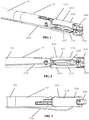
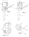
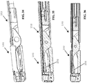
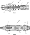
- FIGS 1-6 various aspects of an embodiment of a distal end of a laparoscopic suturing device 10 including an elongate shaft 50 and a jaw assembly 100 are illustrated.
- Figures 1-3 illustrate isometric, side, and top views of the jaw assembly 100 in a stowed configuration retaining a needle 200 and suture 220.
- the jaw assembly 100 In the stowed configuration, the jaw assembly 100 has a relatively small outer diameter for insertion through a laparoscopic surgical port such as a trocar cannula.
- the needle 200 is retained by one of the jaws 110, 160 and the suture 220 extends proximally from the needle along the elongate shaft 50.
- the jaw assembly 100 can be sized for insertion through one of a number of trocar cannula sizes, such as a trocar cannula for receiving 5mm instruments, 10mm instruments, 12mm instruments, or 15mm instruments.
- a trocar cannula for receiving 5mm instruments, 10mm instruments, 12mm instruments, or 15mm instruments.
- the suturing device herein having a low profile stowed jaw assembly configuration can allow a relatively large needle to be deployed through an instrument sized for a relatively small trocar.
- the jaw assembly 100 comprises a first jaw 110 and a second jaw 160 each having a proximal end pivotably coupled to one another and to a distal end 52 of the elongate shaft 50.
- the first jaw 110 comprises a first base jaw 120 having a proximal end pivotably coupled to the elongate shaft 50 and a distal end.
- the first jaw 110 further comprises a first flip jaw 140 pivotably coupled to the distal end of the first base jaw 120.
- the second jaw 160 comprises a second base jaw 170 having a proximal end pivotably coupled to the elongate shaft 50 and a distal end with a second flip jaw 190 pivotably coupled thereto.
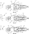
- FIGS. 4-6 further aspects of an embodiment of jaw assembly 100 of the laparoscopic suturing device 10 are illustrated.
- Figures 4-6 side views of a sequence of operation of the jaw assembly from the stowed configuration to a suturing configuration are illustrated.
- Figure 4 illustrates the jaw assembly 100 with the jaws 110, 160 having their base jaws 120, 170 in an open position pivoted such that their distal ends are spaced apart from one another and their flip jaws 140, 190 pivoted to a stowed configuration.
- a latch mechanism can be actuated by a user to pivot the flip jaws 140, 190 from the stowed configuration ( Figure 4 ) through a partially-rotated position ( Figure 5 ) to a suturing configuration ( Figure 6 ).
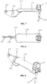
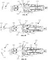
- FIGS 7-9 illustrate side, top and isometric views of the first jaw 110 with the first flip jaw 140 in the suturing configuration with the needle 200 positioned therein.
- a proximal end of the first base jaw 120 can comprise a pivot 124 such as an aperture therethrough to receive a rivet or pinned connection with the second jaw 160 and the distal end 52 of the elongate shaft 50.
- the proximal end of the first base jaw 120 can further comprise an actuation post 126 such that the first base jaw 120 can be pivoted about the pivot 124 by actuation of the post 126 by a jaw actuation mechanism.
- the first base jaw has a jaw body extending distally from the pivot 124 to a distal end.
- the first flip jaw 140 is pivotably coupled to the distal end of the first base jaw 120.
- the first flip jaw 140 can have a needle receiving channel 142 formed therein. With the first flip jaw 140 pivoted to the suturing position, the needle receiving channel 142 is positioned generally transverse to a longitudinal axis of the first base jaw 120 to align with a curvature of the needle. Additionally, with reference to Figure 11 , the needle receiving channel 142 can have an oblong or eccentric cross sectional profile to maintain a rotational orientation of the needle 200 with respect to the needle receiving channel 142.
- the flip jaw's needle receiving channel can be a straight hole to allow the use of a non-rotating core pin during injection molding.
- the straight hole can be angled to be tangent to a circle drawn about the base jaw pivot centerline.
- the core pin can be inserted at an angle to account for a curvature of the needle.
- the core pin hole can be elliptical or an elongated oval to minimize the ability of the curved needle to rotate while seated in the hole.
- the major axis of the elliptical cross section can be oriented in the direction of the needle bend to account for the curvature of the needle.
- the needle In a section view going through the needle hole of the flip jaw in the direction of the needle curvature, the needle can have three contact points to prevent motion.
- the width of the minor axis of the cross sectional ellipse would be the needle diameter plus clearance to prevent the needle from twisting around its longitudinal axis while seated in the hole.
- first flip jaw 140 is pivotably coupled to the first base jaw 120 with a pinned connection.
- first flip jaw 140 can be biased to the suturing position by a biasing member such as a torsion spring 144 positioned about a rotational axis of the flip jaw 140 between the flip jaw 140 and the base jaw 120.
- a first cable 390 and a first shim 360 can extend through a slot in the first base jaw 120 to the first flip jaw 140 to be selectively actuated by a user in an operation sequence through operation of a latching mechanism and toggle mechanism as further described below.
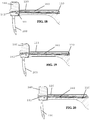
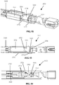
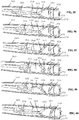
- Figures 14-17 cross sectional views of an embodiment of first jaw 110 about a section line illustrated in Figure 13 are illustrated.
- Figures 14-17 illustrate an operating sequence of the first flip jaw 140 during operation of the latching mechanism such that the first flip jaw is pivoted from the suturing configuration ( Figure 14 ) through partially-stowed configurations ( Figures 15-16 ) to the stowed configuration ( Figure 17 ).
- Operation of the latch mechanism can increase tension on the first cable 390 extending through a slot or channel formed longitudinally in the first base jaw 120 to pivot the first flip jaw 140 relative to the first base jaw.
- first torsion spring 144 ( Figure 12 ) can be used to bias the first flip jaw 140 to a suturing configuration once the suturing device has been introduced to a surgical field
- a tensioned cable can advantageously provide reliable, robust rotation of the flip jaw 140 to the stowed position even where accumulation of fluid or tissue may otherwise resist or prevent rotation of the flip jaw.
- the torsion spring 144 can be replaced with an additional cable such that the latching mechanism utilizes a first cable to pivot the flip jaw to a suturing configuration in an unlatching operation and the illustrated cable to pivot the flip jaw to the stowed configuration in the latching operation.
- Figures 18-20 illustrate cross-sectional views of the first jaw 110 in an operating sequence of the toggle mechanism to advance a distal end of the first shim 360 distally through a slot or shim channel 141 in the first flip jaw 140.
- Distal advancement of the first shim 360 through the shim channel 141 extending through the first flip jaw 140 ( Figure 19 ) locks the first flip jaw 140 in the suturing configuration.
- the shim channel 141 can traverse the needle receiving channel. With the needle 200 positioned in the needle receiving channel 142, a shim notch 210 of the needle is generally aligned with the shim channel 141 of the first flip jaw 140.
- first shim 360 extends the shim distally to engage an interference feature such as a first slot or shim notch 210 ( Figures 28-29 ) in the needle 200 to latch the needle 200 into the first flip jaw ( Figure 20 ).
- the shim channel 141 in the first flip jaw 140 can extend distally beyond the needle receiving channel 142 such that the first shim can engage the first flip jaw 140 proximal and distal of the needle receiving channel 142 and be recessed from tissue.
- a distal surface of the first flip jaw 140 can include a protrusion formed thereon having the slot therein to allow additional distal movement of the first shim 360.
- While the illustrated embodiment includes a single shim to lock both the flip jaw and needle, in other embodiments, it is contemplated that locking of the needle and flip jaw can be accomplished using two separate mechanisms. In these embodiments, a shim can be used to lock the needle, and the flip jaw may be locked by another mechanism such as a second shim, sliding bolt, or pin.
- Figure 22 illustrates a sectional view of the first flip jaw about the sectional plane indicated in broken lines in Figure 21 with the shim 360 partially advanced into the shim channel 141 in the first flip jaw 140.
- the first flip jaw can include a retention feature such as a generally spherical detent 146 positioned therein to engage a corresponding mating recess 214 in the needle 200. This detent engagement can advantageously maintain the position of the needle 200 within the flip jaw when the first flip jaw 140 is in the stowed configuration and before the toggle mechanism has completely advanced the first shim 360 to engage the first shim notch 210 of the needle.
- the detent can have a leaf spring wrapped around the flip jaw that applies force to a ball.
- the ball can reside inside a cylindrical channel that intersects with the needle hole in the flip jaw. The channel narrows near the needle hole to prevent the ball from falling out when no needle is present.
- the needle detent of the flip jaw can be an elastomeric protrusion, a shaped leaf spring tab, or a magnet.
- Figure 23 illustrates the first torsion spring 144 positioned about the pivot axis of the first flip jaw 140.
- the illustrated embodiment of first flip jaw 140 also includes the distal protrusion beyond the needle retention channel.
- one portion of the distal surface of the first flip jaw 140 protrudes from an otherwise generally planar face and includes the shim slot therethrough.
- An adjacent portion of the distal surface of the first flip jaw is recessed such that the first flip jaw 140 can be nested with the second flip jaw in a low profile configuration having a relatively small outer diameter with the jaw assembly in the stowed configuration.
- Figure 24 illustrates the first cable 390 of the latch mechanism coupled to the first flip jaw.
- the first cable 390 is coupled to the first flip jaw at a location offset from the pivot axis such that tension in the cable tends to pivot the first flip jaw towards the stowed configuration.
- the first flip jaw 140 can include a cable slot in an outer surface thereof to receive the first cable 390 when the first flip jaw 140 has been pivoted to the suturing configuration.
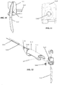
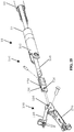
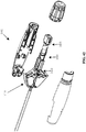
- a distal end of laparoscopic suturing device 10 is illustrated.
- the distal end includes the jaw assembly 100, a jaw actuation mechanism 150, and a distal end 52 of an elongate shaft 50.
- the jaw assembly includes first and second jaws 110, 160 that are pivotably coupled to one another and are substantially similar.
- a suturing device can include jaws having different configurations.
- a jaw assembly can include a single pivotable jaw and a single stationary jaw or only one jaw having a pivotable flip jaw.
- a jaw assembly can include a first jaw comprising a first base jaw and a first flip jaw pivotably coupled to the first base jaw in which the needle can be positioned in a stowed configuration, and a second jaw pivotably coupled to the distal end of the elongate shaft, but having a needle recess therein with no corresponding second flip jaw.
- the second jaw can extend longitudinally distally from the elongate shaft and be pivotably fixed relative to the elongate shaft.
- the jaw actuation mechanism 150 can include a clevis 152 and an actuator 154.
- the clevis 152 can contain guiding slots for the shims and cables to prevent buckling.
- a slotted head of the actuator 154 can support the shims and cables from underneath to prevent buckling inside the clevis.
- the clevis can be formed at or positioned on the distal end 52 of the elongate shaft 50.
- the first and second jaws can be pivotably coupled to the clevis 152.
- the slotted head of the actuator 154 can include actuation slots 156 formed therein.
- a drive rod 158 is slideable within the elongate shaft 50 and is coupled to the actuator 154 to advance the actuator 154 proximally and distally relative to the elongate shaft 50.
- Actuation posts 126 of the first and second base jaws 120, 170 can be positioned within the actuation slots 156 such that longitudinal translation of the actuator 154 opens and closes the base jaws 120, 170.
- Figures 26-27 illustrate the actuator 154, first base jaw 120, and second base jaw 170.
- the actuator 154 can be translated longitudinally to pivot the base jaws 120, 170 relative to one another such that the base jaws 120, 170 can be selectively positioned in an open ( Figure 26 ) or closed ( Figure 27 ) configuration.
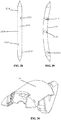
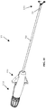
- the needle 200 includes a first shim notch 210 adjacent a first penetrating tip, a second shim notch 212 adjacent a second penetrating tip, a first recess 214 adjacent the first penetrating tip, and a second recess 216 adjacent the second penetrating tip.
- the needle may be passed between the two jaws of the device.
- the needle also has detent features provided by the first and second recesses 214, 216 that allow the jaws to grip the needle while there are no shims locking the needle in place (i.e. in the stowed configuration).
- the needle can also include an aperture 218 for receiving a suture therethrough.
- the suture can include a leader segment such as a braided metallic or polymeric segment coupled to the needle 200 at the aperture 218 and a suturing segment coupled to the leader such as at a crimp joint.
- the leader segment can be knotted, adhered with adhesive, heat forming, or tied about the needle.
- the leader segment and suturing segment can be fixed by knotting the suture and leader, heat forming the suture and leader inside, or adhered with adhesive.
- the suturing segment can be a monofilament polymeric suture.
- this suture construction with a braided leader and monofilament suturing segment can be resilient and enhance usability. Driving the needle through tissue can cause repeated bending of the leader at the needle/leader interface. Having a more flexible material can reduce the likelihood of breakage due to repeated bending of the material at this interface. This flexibility also decreases the amount of force to drive the needle through tissue since the material bends easier and therefore reduces the profile.
- the leader can be inserted into the needle aperture, and then crimped in the aperture. The leader can be connected to the suture by a stainless steel crimped tube. The suture may also be braided to increase flexibility. In some embodiments, the leader can be braided stainless steel to desirably provide enhanced strength and allow welding to the needle.
- the suturing segment can comprise a monofilament or braided suture that is unidirectionally barbed to prevent it from retracting through the tissue and causing wound dehiscence.
- This retention feature would eliminate the need for the surgeon to tie knots after every stitch, which improves the efficiency and ease of the surgery.
- An end of the suture opposite the needle can have an anchor to prevent further migration into the tissue and wound dehiscence.
- the anchor can comprise a fixed or variable diameter loop that the suture is threaded through after the first pass through tissue, resulting in a knotless anchored end. The suturing is then continued without the need to tie any knots.
- the anchor of the suture can comprise a T-shaped anchor. Desirably, a T-shaped anchor can eliminate the need for threading the suture through an anchor loop after the first pass through tissue.
- the needle can comprise a double headed configuration with penetrating tips disposed at opposite ends thereof.
- a central body of the needle can be generally curved.
- the needle is curved to have a bend radius that is equal to the distance from the needle to the base jaw's pivot centerline. This bend radius can help guide the needle through tissue and can minimize the amount of torque that could bend the needle during the piercing of tissue.
- the needle can comprise a single headed configuration with a single penetrating tip disposed at one end thereof.
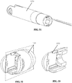
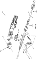
- first base jaw 120 Figure 30
- clevis 152 an embodiment of first base jaw 120 ( Figure 30 ) and an embodiment of clevis 152 are illustrated. As illustrated, both the base jaws 120, 170 and clevis 152 can include passages such as longitudinal slots or channels to facilitate operation of the shims and cables.
- the jaw assembly 100 and jaw actuation mechanism 150 are illustrated with the jaw assembly in a stowed configuration with a needle 200 in one of the jaws.
- Figure 37 illustrates the needle 200 with a suture 220 having a leader 222, crimp 224, and suturing segment 226 attached thereto.
- the actuator comprises a slotted actuation member having actuation slots 156 on opposing surfaces thereof.
- the slotted portion of the actuation member can be positioned between the first base jaw and the second base jaw proximal of the pivot such that actuation posts of the base jaws are each received in an actuation slot 156.
- the suturing device 10 can include a handle assembly 300, an elongate shaft 50, and a jaw assembly 100.
- the handle assembly can extend generally longitudinally from a proximal end to a distal end.
- the handle assembly 300 can include a trigger mechanism 310 including pivotable levers protruding from the handle assembly. In other embodiments, it is contemplated that other handle and trigger configurations can be used with various aspects of jaw assembly mechanism described herein.
- the elongate shaft 50 extends distally from the distal end of the handle assembly and defines a central longitudinal axis of the suturing device 10.
- the jaw assembly 100 can include a pair of opposing jaws pivotably coupled to one another and to the distal end 52 of the elongate shaft 50.
- FIG. 42 an embodiment of handle assembly is illustrated in partially exploded and fully exploded view.
- a handle housing has been removed to illustrate a trigger mechanism 310, closure mechanism 340, toggle mechanism 350, and latch mechanism 380 therein.
- the trigger mechanism 310, closure mechanism 340, toggle mechanism 350, and latch mechanism 380 are illustrated in an exploded arrangement.
- Figure 44 illustrates a top cross sectional view.
- Figure 45 illustrates a side cross sectional view.
- Figure 46 illustrates the handle assembly in an initial position with the needle 200 positioned in first jaw 110.
- Figures 47-48 illustrate an operational sequence as first and second levers 312, 322 of the trigger mechanism are squeezed towards the handle body of handle assembly 300.
- Figures 49-51 illustrate an operational sequence as first and second levers 312, 322 of the trigger mechanism 310 are released from the handle body of handle assembly 300.
- the trigger mechanism can include a pair of opposed levers 312, 322 each pivotable with respect to the handle body. As illustrated, the levers can be pivotably coupled to the handle body adjacent a distal end of the handle assembly. Each of the levers 312, 322 can comprise a drive slot 314, 324 formed therein. As illustrated, the drive slots 314, 324 can include profiles configured to initially close the jaws as the levers are squeezed, then maintain closure upon further movement of the levers 312, 322 while the toggle mechanism is actuated. For example, the drive slots 314, 324 can include a driving segment 316, 326 and a dwell segment 318, 328.
- a closure mechanism 340 can include posts guided by the drive slots 314, 324 and coupled to a proximal end of the drive rod 342, which extends distally through elongate shaft 50 to the jaw actuation mechanism 150. Accordingly, upon initial movement of the levers 312, 322 toward handle body, ( Figures 46-47 ), posts 344 are guided through driving segments 316, 326 of drive slots 314, 324 to longitudinally translate drive rod 342 and close base jaws 120, 170 ( Figure 47 ).
- levers 312, 322 of trigger mechanism are each pivotally coupled to first ends of actuation links 320, 330 extending generally proximally within the handle assembly. Second ends of the actuation links 320, 330 opposite the first ends are coupled to a drive pusher 352 that is longitudinally translatable within the handle body. Longitudinal translation of the drive pusher 352 within the handle body can actuate the toggle mechanism 350 to selectively rotate a toggle tube 354 within the handle body as further described with reference to Figures 52-60 .
- an initial compression of the levers 312, 322 of trigger mechanism ( Figures 46-47 ) actuates actuation links 320, 330 to translate the drive pusher 352 proximally along the toggle tube 354 of the toggle mechanism 350. Further compression of the levers 312, 322 of the trigger mechanism actuates actuation links 320, 330 to translate drive pusher proximally along the toggle tube 354 and rotate the toggle tube about a longitudinal axis of the handle body. As further described herein with reference to Figures 52-60 , rotation of the toggle tube 354 alternately longitudinally advances one of the first shim 360 and the second shim 370 to retain the needle 200 alternately in one of the first and second jaws. Thus, when a user squeezes the levers 312, 322 of the trigger mechanism, the jaws of the jaw assembly are closed, and the needle 200 is passed from one jaw to another.
- the toggle mechanism 350 comprises a drive pusher 352 longitudinally slideable within the handle body by actuation of the trigger mechanism 310.
- the drive pusher 352 can include a forked proximal end having a follower 353 such as a post protruding from each fork of the drive pusher 352.
- a follower 353 such as a post protruding from each fork of the drive pusher 352.
- the drive pusher 352 is illustrated as a monolithically formed component, in other embodiments, fork arms of the pusher could be discrete parts that function in a similar fashion.
- the arms of the pusher can be rigid with a translating pin and spring element keeping the pin in contact with the toggle tube.
- the toggle mechanism 350 can also include a toggle tube 354 rotatable within the handle body.
- the toggle tube 354 comprises a cam drive slot 356 and a shim guide 358.
- the followers 353 of the drive pusher can be positioned in the cam drive slot 356.
- the cam drive slot 356 can include a pair of generally longitudinally extending lead segments and a rotation segment extending at an angle transverse to a longitudinal axis of the handle body between the lead segments.
- the toggle mechanism 350 can further comprise a first shim 360 having a first follower 362 at a proximal end thereof and a second shim 370 having a second follower 372 at a proximal end thereof.
- the followers 362, 372 can comprise protruding posts extending radially inwardly from the shims 360, 370.
- Each of the followers 362, 372 can be positioned in the shim guide 358 of the toggle tube 354.
- the shims can include radially inwardly extending flanges positioned in the shim guide to move the shims without followers.
- the shim guide 358 can have a shim advancement profile such that rotation of the toggle tube 354 within the handle body alternately longitudinally advances or retracts the followers 362, 372 of the shims 360, 370.
- rotation of the toggle tube 354 in a toggle cycle can alternately advance and retract the shims 360, 370 to alternately retain the needle within one or the other of the flip jaws as described with reference to Figures 18-20 .
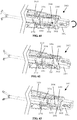
- FIG. 55 an operational sequence of the toggle mechanism is illustrated in sectional views.
- the follower 353 of the drive pusher 352 is positioned in the longitudinal lead segment of the cam drive slot 356, the first shim 360 is in a distally advanced position, and second shim 370 is in a retracted position.
- the follower 353 is advanced longitudinally proximally along the lead segment of the cam drive slot 356, as illustrated in Figures 55-56 .
- the toggle tube 354 is not rotated during this operation, and the first and second shims 360, 370 remain in their initial positions.
- the follower 353 of the drive pusher 352 reaches the rotation segment of the cam drive slot 356.
- the rotation segment can be configured to rotate the toggle tube 354 a predetermined direction upon actuation by the drive pusher 352.
- the rotation segment can have a variable depth profile at an intersection of the rotation segment with the lead segment such that as the follower 353 is advanced into rotation segment, it tends to follow a desired segment of the rotation segment to rotate the toggle tube a predetermined direction.
- the rotation segment extends along the toggle tube 354 transverse to a longitudinal axis of the handle body such that further proximal advancement of the drive pusher 352 and follower 353 relative to the toggle tube rotates the toggle tube 354 within the handle body ( Figures 56-58 ).
- This rotation of the toggle tube 354 likewise rotates the shim guide 358 such that the first shim follower 362 and first shim 360 are withdrawn proximally while second shim follower 372 and second shim 370 are advanced distally.
- the follower 353 is advanced along the rotation segment of the cam drive slot 356, as illustrated in Figures 56-58 .
- the toggle tube 354 is rotated during this operation, and the first and second shims 360, 370 are longitudinally moved.
- the follower 353 of the drive pusher 352 reaches a proximal-most peak of the rotation segment of the cam drive slot 356 ( Figure 58 ).
- the rotation segment can be configured to continue rotating the toggle tube 354 a predetermined direction upon release of the trigger mechanism and distal movement of the drive pusher 352.
- the rotation segment can have a variable depth profile at the proximal-most peak of the rotation segment such that as the follower 353 is advanced along the rotation segment, it tends to follow a desired segment of the rotation segment to rotate the toggle tube a predetermined direction.
- the follower 353 can be disposed at an end of a flexible arm on the drive pusher, which acts as a leaf spring allowing the follower 353 to advance over a depth step.
- the rotation segment extends along the toggle tube 354 transverse to a longitudinal axis of the handle body such that initial distal withdrawal of the drive pusher 352 and follower 353 relative to the toggle tube continues to rotate the toggle tube 354 within the handle body ( Figures 58-59 ).
- this continued rotation is provided by a "double action" stroke of the toggle tube (i.e. rotation during both squeezing and releasing the trigger mechanism).
- This double action stroke desirably halves the stroke length of the trigger mechanism that would otherwise be required to rotate the toggle tube and allows for a lower pressure angle of the follower 353 and cam drive slot 356 system.
- This rotation of the toggle tube 354 likewise rotates the shim guide 358 such that the first shim follower 362 and first shim 360 are withdrawn proximally while second shim follower 372 and second shim 370 are advanced distally.
- the follower 353 is advanced along the rotation segment of the cam drive slot 356, as illustrated in Figures 58-59 .
- the toggle tube 354 is rotated during this operation, and the first and second shims 360, 370 continue to move longitudinally until the second shim 370 reaches a distally advanced position and the first shim reaches a proximally withdrawn position.
- the follower 353 of the drive pusher 352 reaches the longitudinal lead segment of the cam drive slot 356 ( Figure 60 ).
- the rotation segment can have a variable depth profile at the intersection of the rotation segment with the lead segment such that as the follower 353 is withdrawn proximally, it tends to enter the lead segment.
- the follower 353 is advanced along the lead segment of the cam drive slot 356, as illustrated in Figure 60 .
- the second shim 370 remains in the distally advanced position and the first shim 360 remains in the proximally withdrawn position.
- one compress and release cycle of the trigger mechanism cycles the toggle mechanism 350 to rotate the toggle tube 354 180 degrees.
- This rotation of the toggle tube 354 180 degrees repositions one shim 360 from a distally advanced position to a proximally withdrawn position and repositions the other shim 370 from a proximally withdrawn position to a distally advanced position.
- the illustrated toggle mechanism can allow a single trigger mechanism to actuate both a jaw open/close/open cycle and alternately advance a shim to retain a needle in one of the jaws.
- other toggle mechanisms can be used to alternately advance and withdraw shims responsive to a cycle of a trigger mechanism.
- the flip jaws utilize a torsion spring and cable mechanism for rotation between the stowed and suturing configurations.
- the flip jaws rotate about a dowel pin that is held on either end of the flip jaw by the base jaw.
- a distal end of the cable is welded to the bottom of a corresponding flip jaw and is controlled by a latch mechanism in the handle.
- the cables can be attached to corresponding flip jaws by crimping each cable into a slot in the corresponding flip jaw, or having a fitting on the end of each cable that attaches to the corresponding flip jaw.
- the flip jaw cable can also be fixed to the flip jaw by solder or brazing.
- the torsion spring is on the flip jaw's rotation axis, between the flip jaw and base jaw.
- the spring is biased to rotate the flip jaw into the activated, suturing configuration.
- the tension in the cable is released to allow the torsion springs to flip the jaws.
- the cable is tensioned.
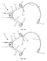
- FIG. 61 illustrates the latch mechanism in an unlatched configuration corresponding to a suturing configuration of the flip jaws.
- the latch mechanism 380 can comprise a latch knob 381 at a proximal end of the handle assembly.
- the latch knob 381 is coupled to a latch tube 382 having first and second guide slots 384, 386 formed therein.
- the latch mechanism further comprises first and second cables 390, 394 extending distally through the handle assembly and elongate shaft and coupled to the flip jaws of the jaw assembly as described above with respect to Figures 14-17 .
- Proximal ends of the cables 390, 394 are coupled to posts 392, 396 positioned within the guide slots 384, 386 of the latch tube 382.
- the posts 392, 396 can be dowel pins protruding from a bearing tube that is coupled to the toggle tube 354 of the toggle mechanism such that proximal movement of the posts 392, 296 withdraws the toggle tube and shims 360, 370 proximally.
- latch tube 382 upon rotation of the latch knob 381, latch tube 382 correspondingly rotates.
- posts 392, 396 are withdrawn proximally by interaction with guide slots 384, 386 of guide tube.
- This proximal movement of posts 392, 396 applies tension to cables 390, 394 to pivot flip jaws from the suturing configuration ( Figure 61 ) to the stowed configuration ( Figure 63 ).
- This proximal movement of posts 392, 396 also withdraws toggle tube 354 and shims 360, 370 proximally.
- the latch mechanism 380 partially rotated, the shims 360, 370 can be withdrawn from both jaws such that the jaw assembly can be reloaded with a new needle, if desired.
- latch knob 381 positions the posts 392, 396 at an end of the guide slots 384, 386 that can be configured, such as with a flat segment or detent, to maintain the latch mechanism 380 in a latched configuration having the flip jaws in the stowed configuration.
- the sequence of Figures 61-63 can be performed in reverse.
- the latch mechanism in the handle both releases the cable tension and also slides the needle locking shims forward in one motion. After the cable tension is released and the springs finish rotating the flip jaws to the activated state, the shims then slide forward into the flip jaws to prevent them from rotating back into the deactivated state. One shim will slide further in order to lock the needle in that jaw.
- the latch mechanism can further comprise a tensioning spring to maintain tension in the cables in both the latched and unlatched configurations of the suturing device.
- each jaw can include a first cable to pivot the flip jaw to a suturing configuration and a second cable to pivot the flip jaw to a stowed configuration.
- the flip jaws can be rotated or pushed into the suturing or stowed configurations using a more rigid cable or rod that can both push and pull the flip jaw, eliminating the need for a torsion spring or two counteracting cables.
- the flip jaws can be pivoted relative to the base jaws by a worm gear and sector, Nitinol actuators, or a lead screw and nut device.
- the elongate shaft 50 can include a cover tube and a spacer member 56 through which the drive rod, cables, and shims extend.
- the spacer member can be an extruded member. The spacer member can prevent buckling of the shims, cables, and drive rod inside the cover tube.
- the needle 200 and suture 420 can include a braided polymeric tube anchor 430.
- the braided polymer tube 430 can be disposed at an end of the suture opposite the needle for use as an anchor for the suture.
- the braided polymer tube 430 anchor can be attached to the end of the suture via welding, adhesive, or another joining method.
- the braided polymer tube 430 with multiple insertion areas provided by voids between adjacent areas of overlapping polymer strands, can provide for a relatively easy target for a surgeon to thread the needle through.
- the needle 200 and suture 420 can include a leader segment 440 comprising a braided polymer tube between the needle 200 and the suture 420.
- the braided polymeric tube can allow for enhanced flexibility of the suture at the needle interface.
- the needle and suture 420 can include a unidirectional barbed suture to facilitate retention of tissue by the suture.
- a smooth monofilament suture can be used with a braided polymer tube anchor and/or braided polymer tube leader.
- the flip jaws, base jaws, clevis, slotted head, drive rod, cables, torsion springs, shims, dowel pins, needle, detent spring, detent ball, cover tube, suture crimp, toggle tube, and rivet can be made of metals such as stainless steel, aluminum, titanium, tungsten, brass, bronze, or alloys of such.
- the shims and/or cables can be made out of Nickel-Titanium (Nitinol) to allow greater flexibility and fatigue life.
- the monofilament or braided suture and flexible multifilament leader can be made of non-bioabsorbable polymers such as polypropylene, nylon, polyester, or silk, or from bioabsorbable polymers such as polydioxanone, polylactic acid, polyglycolide, polylactic-co-glycolic acid, polycaprolactone, or catgut.
- bioabsorbable polymers such as polydioxanone, polylactic acid, polyglycolide, polylactic-co-glycolic acid, polycaprolactone, or catgut.
- some or all of the trigger levers, linkages, latch, knob, shim followers, and drive rod adapters can be made of plastics such as polycarbonate, ABS, polyethylene, polypropylene, PEEK, polyurethane, PVC, acrylic, nylon, polystyrene, acetal, carbon fiber, polyimide, or polyester.
- a suturing device can include a telescopically compressible needle.
- a compression element such as a spring can be contained in the needle and enable two halves of the needle to concentrically compress when subjected to forces greater than tissue puncturing.
- the closure of the jaws can be selectively controlled by the handle with one setting for passage of the needle from jaw to jaw and another setting to enable further closure of the jaws to compress the needle to the low profile state to enable withdrawal through a 5mm trocar.
- the suture is positioned along the elongate shaft with the jaw assembly in a low-profile stowed configuration for insertion through a surgical port. It is contemplated that in other embodiments, the profile of the suturing device can be further reduced for insertion.
- the clevis and outer tube of the elongate shaft can have an axial groove formed therein for the suture to align in during insertion through a trocar, reducing the cross sectional profile of the device.
- suture can be coiled or folded within the two base jaws during insertion through the trocar in order to reduce the cross sectional profile of the device.
- the suturing device can further comprise an introducing tube in which the suture may be coiled or folded for insertion through the trocar.
- This introducing tube can desirably reduce the cross sectional profile of the device during insertion through a trocar and allow the use of larger profile suture anchors.
- the introducing tube can cover the base jaws while they are fully closed in the stowed configuration.
- another instrument such as a surgical grasper can pull the introducing tube off the jaws, releasing the suture inside the body cavity. The introducing tube can then be immediately removed from the body cavity through the other instrument's trocar.
Description
- This application claims the benefit of
U.S. Provisional Patent Application Serial No. 62/217,502 - The present application relates to surgical instruments and more particularly to laparoscopic surgical devices for suturing tissue.
- In surgical procedures, such as minimally invasive surgical procedures in which a surgical site is accessed through a port, it can be desirable to suture tissue with a suturing tool that can be advanced through a relatively low-diameter port to the surgical site. A suturing tool can be configured to advance a needle and attached suture through tissue in the surgical site such that an operator can create a running stitch to approximate tissue. Suturing devices have been made that pass a needle down the trocar with the needle's longitudinal axis perpendicular to the trocar's axis, which limits the length of the needle that may be used in the device to the inner diameter of the trocar. Moreover, current suturing devices typically include operation mechanisms that are complex and cumbersome to operate, requiring multiple operational steps to complete a single stitch. Desirably, an improved suturing device can include increased efficiency, simplicity and ease of use.
-
EP 2462877 A2 discloses a surgical apparatus for use in endoscopic and/or laparoscopic procedures. The surgical apparatus has an elongated body portion, a first jaw member extending from the body portion, and a second jaw member extending from the body portion and opposing the first jaw member. The second jaw member has a split nest slide coupled thereto that is configured to position a surgical incision member in a folded or unfolded position. -
US 5397325 discloses a surgical suturing device which has a tubular elongated shaft terminating into a jaw assembly at the distal end and a handle assembly at the proximal end thereof. The jaw assembly includes a first jaw member pivotally connected to a second jaw member. An actuator rod extending longitudinally within the length of said shaft is connected at its proximal end to said handle assembly and is pivotally connected at its distal end to said jaw assembly. The underside of said first jaw member is provided with a cupped recess having a wheel assembly disposed therein. The wheel assembly includes a needle mount for securably retaining a needle and is configured such that the needle lies within the cupped recess when the jaw members are closed and can be deployed in a protracted position away from the first jaw member when the jaw members are in an open position. - The present invention is defined by the appended independent claim. Preferred embodiments are defined by the dependent claims.
-
-
Figure 1 is an isometric view of an embodiment of jaw assembly for a laparoscopic suturing device in a stowed configuration; -
Figure 2 is a side view of the jaw assembly ofFigure 1 ; -
Figure 3 is a top plan view of the jaw assembly ofFigure 1 ; -
Figure 4 is a side view of the jaw assembly ofFigure 1 with the base jaws in an open state and flip jaws in the stowed configuration; -
Figure 5 is a side view of the jaw assembly ofFigure 1 with the base jaws in an open state and flip jaws partially rotated to a suturing configuration; -
Figure 6 is a side view of the jaw assembly ofFigure 1 with the base jaws in an open state and flip jaws rotated to a suturing configuration; -
Figure 7 is a side view of one jaw of the jaw assembly ofFigure 1 with a suturing needle disposed therein; -
Figure 8 is a top view of the jaw ofFigure 7 ; -
Figure 9 is an isometric view of the jaw ofFigure 7 with the suturing needle disposed therein; -
Figure 10 is a cross-sectional view of a flip jaw and suturing needle of the jaw ofFigure 7 ; -
Figure 11 is a lower plan view of a flip jaw for the jaw ofFigure 7 -
Figure 12 is an exploded view of the jaw ofFigure 7 ; -
Figure 13 is a top plan view of the jaw ofFigure 7 with a section line thereon; -
Figure 14 is a cross sectional view about the section line of the jaw ofFigure 7 in a suturing configuration; -
Figure 15 is a cross sectional view about the section line of the jaw ofFigure 7 partially rotated to a stowed configuration; -
Figure 16 is a cross sectional view about the section line of the jaw ofFigure 7 partially rotated to a stowed configuration; -
Figure 17 is a cross sectional view about the section line of the jaw ofFigure 7 rotated to the stowed configuration; -
Figure 18 is a cross sectional view about the section line of the jaw ofFigure 7 in a suturing configuration; -
Figure 19 is a cross sectional view about the section line of the jaw ofFigure 7 in a suturing configuration with a shim partially advanced to lock the flip jaw; -
Figure 20 is a cross sectional view about the section line of the jaw ofFigure 7 in a suturing configuration with a shim advanced to latch the flip jaw and retain the suturing needle; -
Figure 21 is a perspective view of the flip jaw and needle of the jaw ofFigure 7 with a section plane illustrated in broken lines; -
Figure 22 is a cross sectional view of the flip jaw and needle ofFigure 21 about the section plane; -
Figure 23 is a side view of the flip jaw and needle ofFigure 21 ; -
Figure 24 is a perspective view of the flip jaw and needle ofFigure 21 with an actuation cable attached thereto; -
Figure 25 is an exploded view of an embodiment of jaw assembly and an actuation assembly for a laparoscopic suturing device; -
Figure 26 is a perspective view of base jaws of the jaw assembly ofFigure 25 in an open configuration; -
Figure 27 is a perspective view of base jaws of the jaw assembly ofFigure 25 in a closed configuration; -
Figure 28 is an end view of an embodiment of suturing needle for use in a laparoscopic suturing device; -
Figure 29 is a side view of the suturing needle ofFigure 28 ; -
Figure 30 is an isometric view of a base jaw of the jaw ofFigure 7 ; -
Figure 31 is a perspective view of a clevis of the actuation assembly ofFigure 25 ; -
Figure 32 is a perspective view of the clevis ofFigure 31 with a section plane illustrated in broken lines; -
Figure 33 is a cross sectional view of the clevis ofFigure 31 about the section plane; -
Figure 34 is a perspective view of the jaw assembly and actuation assembly ofFigure 25 with the clevis removed; -
Figure 35 is a perspective cross sectional view of the jaw assembly and actuation assembly ofFigure 34 ; -
Figure 36 is a cross sectional side view of the jaw assembly and actuation assembly ofFigure 34 ; -
Figure 37 is a cross sectional side view of the distal end of the jaw assembly ofFigure 1 in the stowed configuration; -
Figure 38 is an isometric view of an embodiment of a slotted actuator of the actuation assembly ofFigure 25 ; -
Figure 39 is a top view of the slotted actuator ofFigure 38 ; -
Figure 40 is a side view of the slotted actuator ofFigure 38 ; -
Figure 41 is an isometric view of an embodiment of suturing device having the jaw assembly ofFigure 1 ; -
Figure 42 is a partially exploded view of an embodiment of handle assembly of the suturing device ofFigure 41 ; -
Figure 43 is an exploded view of the handle assembly ofFigure 42 ; -
Figure 44 is a cross sectional top view of the handle assembly ofFigure 42 ; -
Figure 45 is a cross sectional side view of the handle assembly ofFigure 42 ; -
Figure 46 is a partial cross sectional view of the suturing device ofFigure 41 in an open configuration with a top cross sectional view of the handle assembly; -
Figure 47 is a partial cross sectional view of the suturing device ofFigure 41 in a partially-closed configuration with a top cross sectional view of the handle assembly; -
Figure 48 is a partial cross sectional view of the suturing device ofFigure 41 in a closed configuration with a top cross sectional view of the handle assembly; -
Figure 49 is a partial cross sectional view of the suturing device ofFigure 41 in a closed configuration with a top cross sectional view of the handle assembly; -
Figure 50 is a partial cross sectional view of the suturing device ofFigure 41 in a partially closed configuration with a top cross sectional view of the handle assembly; -
Figure 51 is a partial cross sectional view of the suturing device ofFigure 41 in an open configuration with a top cross sectional view of the handle assembly; -
Figure 52 is an isometric view of embodiments of toggling and latch mechanisms of the handle assembly ofFigure 41 -
Figure 53 is a side view of the toggling and latch mechanisms ofFigure 52 ; -
Figure 54 is a top view of the toggling and latch mechanisms ofFigure 52 ; -
Figure 55 is a section view of the toggling mechanism ofFigure 52 with a follower in a first position during a toggle cycle; -
Figure 56 is a section view of the toggling mechanism ofFigure 52 with a follower in a second position during a toggle cycle; -
Figure 57 is a section view of the toggling mechanism ofFigure 52 with a follower in a third position during a toggle cycle; -
Figure 58 is a section view of the toggling mechanism ofFigure 52 with a follower in a fourth position during a toggle cycle; -
Figure 59 is a section view of the toggling mechanism ofFigure 52 with a follower in a fifth position during a toggle cycle; -
Figure 60 is a section view of the toggling mechanism ofFigure 52 with a follower in a first position after a completed toggle cycle; -
Figure 61 is a partial cross sectional view of the suturing device ofFigure 41 in an open configuration with a side cross sectional view of the handle assembly; -
Figure 62 is a partial cross sectional view of the suturing device ofFigure 41 with flip jaws rotated by the latch mechanism to a partially stowed configuration with a side cross sectional view of the handle assembly; -
Figure 63 is a partial cross sectional view of the suturing device ofFigure 41 with flip jaws rotated by the latch mechanism to a stowed configuration with a side cross sectional view of the handle assembly; -
Figure 64 is a cross sectional view of an embodiment of elongate shaft of the suturing device ofFigure 41 ; -
Figure 65 is a side view of an embodiment of the jaw assembly of a suturing device having a needle with a barbed suture and a braided anchor; and -
Figure 66 is a side view of an embodiment of the jaw assembly of a suturing device having a needle with a barbed suture, a braided leader, and a braided anchor. - In various embodiments, a suturing system is disclosed herein that can increase a surgeon's efficiency at applying sutures to tissue inside a patient during minimally invasive surgeries such as laparoscopic surgeries. The suturing device passes a needle with an attached suture back and forth through tissue between alternate jaws of a jaw assembly by driving the needle through tissue and using a receiving jaw to grip the needle while a driving jaw releases the needle.
- During clinical use, an access device such as a trocar is first placed through a body wall and into a body cavity, leaving the trocar cannula disposed within the body cavity and across the body wall. The suturing devices discussed herein can utilize a suture that is attached to the center of a needle with sharp points on both ends so it may be passed back and forth through tissue. In order to fit the device down a relatively low diameter trocar such as a 5mm trocar, the needle can be stowed away during insertion and removal through the trocar in order to lower the diametric profile of the device. When the needle is stowed away the device is considered to be in the deactivated or stowed state. When inside the body cavity or during needle loading outside the body, the device can be deployed into its activated or suturing state. While in its activated state, the device is able to drive a suturing needle through tissue and pass the needle and attached suture from a driving jaw to the receiving jaw.
- Advantageously, the stowed needle configuration of the devices herein can allow the use of a needle with a length that otherwise would not fit down a 5mm trocar. Allowing the surgeon to use a smaller trocar has considerable advantages, such as reducing post-operative healing time and scarring of the patient. Larger common size of trocars such as 10mm, 12mm and 15mm would require a significantly larger incision than a 5mm trocar. The stowed configuration of the devices herein obviates needle-length limitations of conventional suturing devices. The devices described herein can therefore stitch using a longer needle than the conventional 10mm trocar diameter suturing devices while being able to traverse through a 5mm trocar. This use of a longer needle can advantageously allow more tissue or thicker tissue to be penetrated, allowing the surgeon to suture more than 10mm devices allow.
- With reference to
Figures 1-6 , various aspects of an embodiment of a distal end of alaparoscopic suturing device 10 including anelongate shaft 50 and ajaw assembly 100 are illustrated.Figures 1-3 illustrate isometric, side, and top views of thejaw assembly 100 in a stowed configuration retaining aneedle 200 andsuture 220. In the stowed configuration, thejaw assembly 100 has a relatively small outer diameter for insertion through a laparoscopic surgical port such as a trocar cannula. As illustrated, with the jaw assembly in the stowed configuration, theneedle 200 is retained by one of thejaws suture 220 extends proximally from the needle along theelongate shaft 50. - In certain embodiments, the
jaw assembly 100 can be sized for insertion through one of a number of trocar cannula sizes, such as a trocar cannula for receiving 5mm instruments, 10mm instruments, 12mm instruments, or 15mm instruments. Advantageously, the suturing device herein having a low profile stowed jaw assembly configuration can allow a relatively large needle to be deployed through an instrument sized for a relatively small trocar. - With continued reference to
Figures 1-3 , in the illustrated embodiment, thejaw assembly 100 comprises afirst jaw 110 and asecond jaw 160 each having a proximal end pivotably coupled to one another and to adistal end 52 of theelongate shaft 50. Thefirst jaw 110 comprises afirst base jaw 120 having a proximal end pivotably coupled to theelongate shaft 50 and a distal end. Thefirst jaw 110 further comprises afirst flip jaw 140 pivotably coupled to the distal end of thefirst base jaw 120. In the illustrated embodiment, similarly, thesecond jaw 160 comprises asecond base jaw 170 having a proximal end pivotably coupled to theelongate shaft 50 and a distal end with asecond flip jaw 190 pivotably coupled thereto. - With reference to
Figures 4-6 , further aspects of an embodiment ofjaw assembly 100 of thelaparoscopic suturing device 10 are illustrated. InFigures 4-6 , side views of a sequence of operation of the jaw assembly from the stowed configuration to a suturing configuration are illustrated.Figure 4 illustrates thejaw assembly 100 with thejaws base jaws flip jaws Figures 61-63 , a latch mechanism can be actuated by a user to pivot theflip jaws Figure 4 ) through a partially-rotated position (Figure 5 ) to a suturing configuration (Figure 6 ). - With reference to
Figures 7-12 , various aspects of afirst jaw 110 of an embodiment ofjaw assembly 100 and aneedle 200 are illustrated.Figures 7-9 illustrate side, top and isometric views of thefirst jaw 110 with thefirst flip jaw 140 in the suturing configuration with theneedle 200 positioned therein. A proximal end of thefirst base jaw 120 can comprise apivot 124 such as an aperture therethrough to receive a rivet or pinned connection with thesecond jaw 160 and thedistal end 52 of theelongate shaft 50. The proximal end of thefirst base jaw 120 can further comprise anactuation post 126 such that thefirst base jaw 120 can be pivoted about thepivot 124 by actuation of thepost 126 by a jaw actuation mechanism. The first base jaw has a jaw body extending distally from thepivot 124 to a distal end. Thefirst flip jaw 140 is pivotably coupled to the distal end of thefirst base jaw 120. - With reference to
Figure 10 , a cross sectional view of the distal end of thefirst jaw 110 is illustrated. Thefirst flip jaw 140 can have aneedle receiving channel 142 formed therein. With thefirst flip jaw 140 pivoted to the suturing position, theneedle receiving channel 142 is positioned generally transverse to a longitudinal axis of thefirst base jaw 120 to align with a curvature of the needle. Additionally, with reference toFigure 11 , theneedle receiving channel 142 can have an oblong or eccentric cross sectional profile to maintain a rotational orientation of theneedle 200 with respect to theneedle receiving channel 142. - With continued reference to
Figure 10 , in some embodiments, to increase manufacturability, the flip jaw's needle receiving channel can be a straight hole to allow the use of a non-rotating core pin during injection molding. The straight hole can be angled to be tangent to a circle drawn about the base jaw pivot centerline. The core pin can be inserted at an angle to account for a curvature of the needle. The core pin hole can be elliptical or an elongated oval to minimize the ability of the curved needle to rotate while seated in the hole. The major axis of the elliptical cross section can be oriented in the direction of the needle bend to account for the curvature of the needle. In a section view going through the needle hole of the flip jaw in the direction of the needle curvature, the needle can have three contact points to prevent motion. The width of the minor axis of the cross sectional ellipse would be the needle diameter plus clearance to prevent the needle from twisting around its longitudinal axis while seated in the hole. - With reference to
Figure 12 , an exploded view of an embodiment of thefirst jaw 110 is illustrated. In the illustrated embodiment, thefirst flip jaw 140 is pivotably coupled to thefirst base jaw 120 with a pinned connection. In some embodiments, thefirst flip jaw 140 can be biased to the suturing position by a biasing member such as atorsion spring 144 positioned about a rotational axis of theflip jaw 140 between theflip jaw 140 and thebase jaw 120. Afirst cable 390 and afirst shim 360 can extend through a slot in thefirst base jaw 120 to thefirst flip jaw 140 to be selectively actuated by a user in an operation sequence through operation of a latching mechanism and toggle mechanism as further described below. - With reference to
Figures 14-17 , cross sectional views of an embodiment offirst jaw 110 about a section line illustrated inFigure 13 are illustrated.Figures 14-17 illustrate an operating sequence of thefirst flip jaw 140 during operation of the latching mechanism such that the first flip jaw is pivoted from the suturing configuration (Figure 14 ) through partially-stowed configurations (Figures 15-16 ) to the stowed configuration (Figure 17 ). Operation of the latch mechanism can increase tension on thefirst cable 390 extending through a slot or channel formed longitudinally in thefirst base jaw 120 to pivot thefirst flip jaw 140 relative to the first base jaw. While the first torsion spring 144 (Figure 12 ) can be used to bias thefirst flip jaw 140 to a suturing configuration once the suturing device has been introduced to a surgical field, it is contemplated that following use of the suturing device, a tensioned cable can advantageously provide reliable, robust rotation of theflip jaw 140 to the stowed position even where accumulation of fluid or tissue may otherwise resist or prevent rotation of the flip jaw. In other embodiments, thetorsion spring 144 can be replaced with an additional cable such that the latching mechanism utilizes a first cable to pivot the flip jaw to a suturing configuration in an unlatching operation and the illustrated cable to pivot the flip jaw to the stowed configuration in the latching operation. -
Figures 18-20 illustrate cross-sectional views of thefirst jaw 110 in an operating sequence of the toggle mechanism to advance a distal end of thefirst shim 360 distally through a slot orshim channel 141 in thefirst flip jaw 140. Distal advancement of thefirst shim 360 through theshim channel 141 extending through the first flip jaw 140 (Figure 19 ) locks thefirst flip jaw 140 in the suturing configuration. Theshim channel 141 can traverse the needle receiving channel. With theneedle 200 positioned in theneedle receiving channel 142, ashim notch 210 of the needle is generally aligned with theshim channel 141 of thefirst flip jaw 140. Accordingly, further advancement of thefirst shim 360 extends the shim distally to engage an interference feature such as a first slot or shim notch 210 (Figures 28-29 ) in theneedle 200 to latch theneedle 200 into the first flip jaw (Figure 20 ). Theshim channel 141 in thefirst flip jaw 140 can extend distally beyond theneedle receiving channel 142 such that the first shim can engage thefirst flip jaw 140 proximal and distal of theneedle receiving channel 142 and be recessed from tissue. In some embodiments, a distal surface of thefirst flip jaw 140 can include a protrusion formed thereon having the slot therein to allow additional distal movement of thefirst shim 360. While the illustrated embodiment includes a single shim to lock both the flip jaw and needle, in other embodiments, it is contemplated that locking of the needle and flip jaw can be accomplished using two separate mechanisms. In these embodiments, a shim can be used to lock the needle, and the flip jaw may be locked by another mechanism such as a second shim, sliding bolt, or pin. - With reference to
Figures 21-24 , various views of thefirst flip jaw 140,needle 200 and first shim 360 (Figures 21-22 ) are illustrated.Figure 22 illustrates a sectional view of the first flip jaw about the sectional plane indicated in broken lines inFigure 21 with theshim 360 partially advanced into theshim channel 141 in thefirst flip jaw 140. The first flip jaw can include a retention feature such as a generallyspherical detent 146 positioned therein to engage acorresponding mating recess 214 in theneedle 200. This detent engagement can advantageously maintain the position of theneedle 200 within the flip jaw when thefirst flip jaw 140 is in the stowed configuration and before the toggle mechanism has completely advanced thefirst shim 360 to engage thefirst shim notch 210 of the needle. In some embodiments, the detent can have a leaf spring wrapped around the flip jaw that applies force to a ball. The ball can reside inside a cylindrical channel that intersects with the needle hole in the flip jaw. The channel narrows near the needle hole to prevent the ball from falling out when no needle is present. When a needle is in the flip jaw, the ball is pressed into a corresponding recess in the needle to retain it while the shims are not locking the needle in place. In other embodiments, instead of the ball of the illustrated embodiment, the needle detent of the flip jaw can be an elastomeric protrusion, a shaped leaf spring tab, or a magnet. -
Figure 23 illustrates thefirst torsion spring 144 positioned about the pivot axis of thefirst flip jaw 140. The illustrated embodiment of firstflip jaw 140 also includes the distal protrusion beyond the needle retention channel. As illustrated, one portion of the distal surface of thefirst flip jaw 140 protrudes from an otherwise generally planar face and includes the shim slot therethrough. An adjacent portion of the distal surface of the first flip jaw is recessed such that thefirst flip jaw 140 can be nested with the second flip jaw in a low profile configuration having a relatively small outer diameter with the jaw assembly in the stowed configuration. -
Figure 24 illustrates thefirst cable 390 of the latch mechanism coupled to the first flip jaw. Thefirst cable 390 is coupled to the first flip jaw at a location offset from the pivot axis such that tension in the cable tends to pivot the first flip jaw towards the stowed configuration. Thefirst flip jaw 140 can include a cable slot in an outer surface thereof to receive thefirst cable 390 when thefirst flip jaw 140 has been pivoted to the suturing configuration. - With reference to
Figure 25 , an exploded view of a distal end oflaparoscopic suturing device 10 is illustrated. As illustrated, the distal end includes thejaw assembly 100, ajaw actuation mechanism 150, and adistal end 52 of anelongate shaft 50. In the illustrated embodiment, the jaw assembly includes first andsecond jaws - With continued reference to
Figure 25 , thejaw actuation mechanism 150 can include aclevis 152 and anactuator 154. Theclevis 152 can contain guiding slots for the shims and cables to prevent buckling. A slotted head of theactuator 154 can support the shims and cables from underneath to prevent buckling inside the clevis. The clevis can be formed at or positioned on thedistal end 52 of theelongate shaft 50. The first and second jaws can be pivotably coupled to theclevis 152. The slotted head of theactuator 154 can includeactuation slots 156 formed therein. In the illustrated embodiment, adrive rod 158 is slideable within theelongate shaft 50 and is coupled to theactuator 154 to advance theactuator 154 proximally and distally relative to theelongate shaft 50. Actuation posts 126 of the first andsecond base jaws actuation slots 156 such that longitudinal translation of theactuator 154 opens and closes thebase jaws -
Figures 26-27 illustrate theactuator 154,first base jaw 120, andsecond base jaw 170. As illustrated, theactuator 154 can be translated longitudinally to pivot thebase jaws base jaws Figure 26 ) or closed (Figure 27 ) configuration. - With reference to
Figures 28-29 , an embodiment of suturing needle is illustrated. As illustrated, theneedle 200 includes afirst shim notch 210 adjacent a first penetrating tip, asecond shim notch 212 adjacent a second penetrating tip, afirst recess 214 adjacent the first penetrating tip, and asecond recess 216 adjacent the second penetrating tip. By alternating which shim is locking the needle, the needle may be passed between the two jaws of the device. Advantageously, the needle also has detent features provided by the first andsecond recesses aperture 218 for receiving a suture therethrough. It is contemplated that in some embodiments, the suture can include a leader segment such as a braided metallic or polymeric segment coupled to theneedle 200 at theaperture 218 and a suturing segment coupled to the leader such as at a crimp joint. In various embodiments, the leader segment can be knotted, adhered with adhesive, heat forming, or tied about the needle. In various embodiments, the leader segment and suturing segment can be fixed by knotting the suture and leader, heat forming the suture and leader inside, or adhered with adhesive. The suturing segment can be a monofilament polymeric suture. - Desirably, this suture construction with a braided leader and monofilament suturing segment can be resilient and enhance usability. Driving the needle through tissue can cause repeated bending of the leader at the needle/leader interface. Having a more flexible material can reduce the likelihood of breakage due to repeated bending of the material at this interface. This flexibility also decreases the amount of force to drive the needle through tissue since the material bends easier and therefore reduces the profile. In some embodiments, the leader can be inserted into the needle aperture, and then crimped in the aperture. The leader can be connected to the suture by a stainless steel crimped tube. The suture may also be braided to increase flexibility. In some embodiments, the leader can be braided stainless steel to desirably provide enhanced strength and allow welding to the needle.
- In some embodiments, the suturing segment can comprise a monofilament or braided suture that is unidirectionally barbed to prevent it from retracting through the tissue and causing wound dehiscence. This retention feature would eliminate the need for the surgeon to tie knots after every stitch, which improves the efficiency and ease of the surgery. An end of the suture opposite the needle can have an anchor to prevent further migration into the tissue and wound dehiscence. In some embodiments, the anchor can comprise a fixed or variable diameter loop that the suture is threaded through after the first pass through tissue, resulting in a knotless anchored end. The suturing is then continued without the need to tie any knots. In other embodiments, the anchor of the suture can comprise a T-shaped anchor. Desirably, a T-shaped anchor can eliminate the need for threading the suture through an anchor loop after the first pass through tissue.
- With continued reference to
Figure 29 , in the illustrated embodiment, the needle can comprise a double headed configuration with penetrating tips disposed at opposite ends thereof. A central body of the needle can be generally curved. In some embodiments, the needle is curved to have a bend radius that is equal to the distance from the needle to the base jaw's pivot centerline. This bend radius can help guide the needle through tissue and can minimize the amount of torque that could bend the needle during the piercing of tissue. In other embodiments, the needle can comprise a single headed configuration with a single penetrating tip disposed at one end thereof. - With reference to
Figures 30-33 , an embodiment of first base jaw 120 (Figure 30 ) and an embodiment ofclevis 152 are illustrated. As illustrated, both thebase jaws clevis 152 can include passages such as longitudinal slots or channels to facilitate operation of the shims and cables. - With reference to
Figures 34-37 , thejaw assembly 100 andjaw actuation mechanism 150 are illustrated with the jaw assembly in a stowed configuration with aneedle 200 in one of the jaws.Figure 37 illustrates theneedle 200 with asuture 220 having aleader 222, crimp 224, andsuturing segment 226 attached thereto. - With reference to
Figures 38-40 , an embodiment ofactuator 154 for the jaw actuation mechanism is illustrated. As illustrated, the actuator comprises a slotted actuation member havingactuation slots 156 on opposing surfaces thereof. The slotted portion of the actuation member can be positioned between the first base jaw and the second base jaw proximal of the pivot such that actuation posts of the base jaws are each received in anactuation slot 156. - With reference to
Figure 41 , an embodiment oflaparoscopic suturing device 10 is illustrated. Thesuturing device 10 can include ahandle assembly 300, anelongate shaft 50, and ajaw assembly 100. The handle assembly can extend generally longitudinally from a proximal end to a distal end. Thehandle assembly 300 can include atrigger mechanism 310 including pivotable levers protruding from the handle assembly. In other embodiments, it is contemplated that other handle and trigger configurations can be used with various aspects of jaw assembly mechanism described herein. Theelongate shaft 50 extends distally from the distal end of the handle assembly and defines a central longitudinal axis of thesuturing device 10. Thejaw assembly 100 can include a pair of opposing jaws pivotably coupled to one another and to thedistal end 52 of theelongate shaft 50. - With reference to
Figures 42-43 , an embodiment of handle assembly is illustrated in partially exploded and fully exploded view. InFigure 42 , a handle housing has been removed to illustrate atrigger mechanism 310,closure mechanism 340,toggle mechanism 350, andlatch mechanism 380 therein. InFigure 43 , thetrigger mechanism 310,closure mechanism 340,toggle mechanism 350, andlatch mechanism 380 are illustrated in an exploded arrangement. - With reference to
Figures 44-45 , cross sectional views of an embodiment of handle assembly are illustrated.Figure 44 illustrates a top cross sectional view.Figure 45 illustrates a side cross sectional view. - With reference to
Figures 46-51 , partial cross-sectional views of the handle assembly are illustrated along with corresponding positions of thejaw assembly 100 andneedle 200.Figure 46 illustrates the handle assembly in an initial position with theneedle 200 positioned infirst jaw 110.Figures 47-48 illustrate an operational sequence as first andsecond levers handle assembly 300.Figures 49-51 illustrate an operational sequence as first andsecond levers trigger mechanism 310 are released from the handle body ofhandle assembly 300. - With reference to
Figures 46-48 , the trigger mechanism can include a pair ofopposed levers levers drive slot drive slots levers drive slots driving segment dwell segment closure mechanism 340 can include posts guided by thedrive slots drive rod 342, which extends distally throughelongate shaft 50 to thejaw actuation mechanism 150. Accordingly, upon initial movement of thelevers Figures 46-47 ), posts 344 are guided through drivingsegments drive slots drive rod 342 andclose base jaws 120, 170 (Figure 47 ). - With reference to
Figures 47-48 , further compression of thelevers posts 344 of the closure mechanism moving indwell segments drive slots drive rod 342. However, thelevers actuation links drive pusher 352 that is longitudinally translatable within the handle body. Longitudinal translation of thedrive pusher 352 within the handle body can actuate thetoggle mechanism 350 to selectively rotate atoggle tube 354 within the handle body as further described with reference toFigures 52-60 . - With reference to
Figures 46-48 , an initial compression of thelevers Figures 46-47 ) actuatesactuation links drive pusher 352 proximally along thetoggle tube 354 of thetoggle mechanism 350. Further compression of thelevers actuation links toggle tube 354 and rotate the toggle tube about a longitudinal axis of the handle body. As further described herein with reference toFigures 52-60 , rotation of thetoggle tube 354 alternately longitudinally advances one of thefirst shim 360 and thesecond shim 370 to retain theneedle 200 alternately in one of the first and second jaws. Thus, when a user squeezes thelevers needle 200 is passed from one jaw to another. - With reference to
Figures 49-51 , releasing thelevers posts 344 of theclosure mechanism 340 along thedwell segments slots 314, 324 (Figures 49-50 ). During this initial opening movement, thetoggle tube 354 continues to rotate, completing the advancement of one of the shims. As the levers continue to spread, theposts 344 of theclosure mechanism 340 ride along the drivingsegments slots 314, 324 (Figures 50-51 ) such that thedrive rod 342 is longitudinally translated to return the jaw assembly to an open configuration. This further movement translates thedrive pusher 352 distally alongtoggle tube 354 oftoggle mechanism 350. - With reference to
Figures 52-54 , various aspects of the toggle mechanism are illustrated in isometric, top, and side views. As illustrated, thetoggle mechanism 350 comprises adrive pusher 352 longitudinally slideable within the handle body by actuation of thetrigger mechanism 310. Thedrive pusher 352 can include a forked proximal end having afollower 353 such as a post protruding from each fork of thedrive pusher 352. While thedrive pusher 352 is illustrated as a monolithically formed component, in other embodiments, fork arms of the pusher could be discrete parts that function in a similar fashion. In some embodiments, the arms of the pusher can be rigid with a translating pin and spring element keeping the pin in contact with the toggle tube. Thetoggle mechanism 350 can also include atoggle tube 354 rotatable within the handle body. As illustrated, thetoggle tube 354 comprises acam drive slot 356 and ashim guide 358. Thefollowers 353 of the drive pusher can be positioned in thecam drive slot 356. Thecam drive slot 356 can include a pair of generally longitudinally extending lead segments and a rotation segment extending at an angle transverse to a longitudinal axis of the handle body between the lead segments. - With continued reference to
Figures 52-54 , thetoggle mechanism 350 can further comprise afirst shim 360 having afirst follower 362 at a proximal end thereof and asecond shim 370 having asecond follower 372 at a proximal end thereof. Thefollowers shims followers shim guide 358 of thetoggle tube 354. In other embodiments, the shims can include radially inwardly extending flanges positioned in the shim guide to move the shims without followers. Theshim guide 358 can have a shim advancement profile such that rotation of thetoggle tube 354 within the handle body alternately longitudinally advances or retracts thefollowers shims toggle tube 354 in a toggle cycle can alternately advance and retract theshims Figures 18-20 . - With reference to
Figures 55-60 , an operational sequence of the toggle mechanism is illustrated in sectional views. InFigure 55 , thefollower 353 of thedrive pusher 352 is positioned in the longitudinal lead segment of thecam drive slot 356, thefirst shim 360 is in a distally advanced position, andsecond shim 370 is in a retracted position. During an initial squeezing operation of the trigger mechanism, corresponding to closing the jaw assembly as described above with reference toFigures 46-47 , thefollower 353 is advanced longitudinally proximally along the lead segment of thecam drive slot 356, as illustrated inFigures 55-56 . Thetoggle tube 354 is not rotated during this operation, and the first andsecond shims - With reference to
Figures 56-58 , during the operational sequence of thetoggle mechanism 350, once the trigger mechanism is squeezed beyond jaw closure (Figures 47-48 ), thefollower 353 of thedrive pusher 352 reaches the rotation segment of thecam drive slot 356. The rotation segment can be configured to rotate the toggle tube 354 a predetermined direction upon actuation by thedrive pusher 352. For example, the rotation segment can have a variable depth profile at an intersection of the rotation segment with the lead segment such that as thefollower 353 is advanced into rotation segment, it tends to follow a desired segment of the rotation segment to rotate the toggle tube a predetermined direction. The rotation segment extends along thetoggle tube 354 transverse to a longitudinal axis of the handle body such that further proximal advancement of thedrive pusher 352 andfollower 353 relative to the toggle tube rotates thetoggle tube 354 within the handle body (Figures 56-58 ). This rotation of thetoggle tube 354 likewise rotates theshim guide 358 such that thefirst shim follower 362 andfirst shim 360 are withdrawn proximally whilesecond shim follower 372 andsecond shim 370 are advanced distally. Thus, during a continued squeezing operation of the trigger mechanism, corresponding to closing the jaw assembly as described above with reference toFigures 47-48 , thefollower 353 is advanced along the rotation segment of thecam drive slot 356, as illustrated inFigures 56-58 . Thetoggle tube 354 is rotated during this operation, and the first andsecond shims - With reference to
Figures 58-60 , during the operational sequence of thetoggle mechanism 350, once the trigger mechanism is released from a fully squeezed orientation (Figures 49-51 ), thefollower 353 of thedrive pusher 352 reaches a proximal-most peak of the rotation segment of the cam drive slot 356 (Figure 58 ). The rotation segment can be configured to continue rotating the toggle tube 354 a predetermined direction upon release of the trigger mechanism and distal movement of thedrive pusher 352. For example, the rotation segment can have a variable depth profile at the proximal-most peak of the rotation segment such that as thefollower 353 is advanced along the rotation segment, it tends to follow a desired segment of the rotation segment to rotate the toggle tube a predetermined direction. Furthermore, thefollower 353 can be disposed at an end of a flexible arm on the drive pusher, which acts as a leaf spring allowing thefollower 353 to advance over a depth step. The rotation segment extends along thetoggle tube 354 transverse to a longitudinal axis of the handle body such that initial distal withdrawal of thedrive pusher 352 andfollower 353 relative to the toggle tube continues to rotate thetoggle tube 354 within the handle body (Figures 58-59 ). Advantageously, this continued rotation is provided by a "double action" stroke of the toggle tube (i.e. rotation during both squeezing and releasing the trigger mechanism). This double action stroke desirably halves the stroke length of the trigger mechanism that would otherwise be required to rotate the toggle tube and allows for a lower pressure angle of thefollower 353 andcam drive slot 356 system. This rotation of thetoggle tube 354 likewise rotates theshim guide 358 such that thefirst shim follower 362 andfirst shim 360 are withdrawn proximally whilesecond shim follower 372 andsecond shim 370 are advanced distally. Thus, during an initial release operation of the trigger mechanism, corresponding to the initial dwell portion as described above with reference toFigures 49-50 , thefollower 353 is advanced along the rotation segment of thecam drive slot 356, as illustrated inFigures 58-59 . Thetoggle tube 354 is rotated during this operation, and the first andsecond shims second shim 370 reaches a distally advanced position and the first shim reaches a proximally withdrawn position. - With reference to
Figure 60 , during the operational sequence of thetoggle mechanism 350, as the trigger mechanism continues to travel to a fully released position (Figures 50-51 ), thefollower 353 of thedrive pusher 352 reaches the longitudinal lead segment of the cam drive slot 356 (Figure 60 ). The rotation segment can have a variable depth profile at the intersection of the rotation segment with the lead segment such that as thefollower 353 is withdrawn proximally, it tends to enter the lead segment. Thus continued distal withdrawal of thedrive pusher 352 andfollower 353 relative to the toggle tube along the longitudinally- extending lead segment maintains the rotational orientation of thetoggle tube 354 within the handle body (Figure 60 ). Thus, during a fully released operation of the trigger mechanism, corresponding to the jaw opening portion as described above with reference toFigures 50-51 , thefollower 353 is advanced along the lead segment of thecam drive slot 356, as illustrated inFigure 60 . During this operation, thesecond shim 370 remains in the distally advanced position and thefirst shim 360 remains in the proximally withdrawn position. - Accordingly, in the illustrated embodiment, one compress and release cycle of the trigger mechanism cycles the
toggle mechanism 350 to rotate thetoggle tube 354 180 degrees. This rotation of thetoggle tube 354 180 degrees repositions oneshim 360 from a distally advanced position to a proximally withdrawn position and repositions theother shim 370 from a proximally withdrawn position to a distally advanced position. Thus, advantageously, the illustrated toggle mechanism can allow a single trigger mechanism to actuate both a jaw open/close/open cycle and alternately advance a shim to retain a needle in one of the jaws. In other embodiments, other toggle mechanisms can be used to alternately advance and withdraw shims responsive to a cycle of a trigger mechanism. - As discussed above, the flip jaws utilize a torsion spring and cable mechanism for rotation between the stowed and suturing configurations. The flip jaws rotate about a dowel pin that is held on either end of the flip jaw by the base jaw. In some embodiments, a distal end of the cable is welded to the bottom of a corresponding flip jaw and is controlled by a latch mechanism in the handle. In other embodiments, the cables can be attached to corresponding flip jaws by crimping each cable into a slot in the corresponding flip jaw, or having a fitting on the end of each cable that attaches to the corresponding flip jaw. In other embodiments, the flip jaw cable can also be fixed to the flip jaw by solder or brazing. The torsion spring is on the flip jaw's rotation axis, between the flip jaw and base jaw. The spring is biased to rotate the flip jaw into the activated, suturing configuration. To rotate the flip jaws to the activated state, the tension in the cable is released to allow the torsion springs to flip the jaws. To rotate the flip jaws into the deactivated state, the cable is tensioned.
- With reference to
Figure 61-63 , an operational sequence of thelatch mechanism 380 is illustrated.Figure 61 illustrates the latch mechanism in an unlatched configuration corresponding to a suturing configuration of the flip jaws. Thelatch mechanism 380 can comprise alatch knob 381 at a proximal end of the handle assembly. In the illustrated embodiment, thelatch knob 381 is coupled to alatch tube 382 having first andsecond guide slots second cables Figures 14-17 . Proximal ends of thecables posts guide slots latch tube 382. Theposts toggle tube 354 of the toggle mechanism such that proximal movement of theposts 392, 296 withdraws the toggle tube and shims 360, 370 proximally. - With continued reference to
Figures 61-63 , upon rotation of thelatch knob 381,latch tube 382 correspondingly rotates. Thus, posts 392, 396 are withdrawn proximally by interaction withguide slots posts cables Figure 61 ) to the stowed configuration (Figure 63 ). This proximal movement ofposts toggle tube 354 andshims latch mechanism 380 partially rotated, theshims latch knob 381 positions theposts guide slots latch mechanism 380 in a latched configuration having the flip jaws in the stowed configuration. - When it is desired to unlatch the device to position the flip jaws in the suturing configuration, the sequence of
Figures 61-63 can be performed in reverse. In the unlatching sequence, the latch mechanism in the handle both releases the cable tension and also slides the needle locking shims forward in one motion. After the cable tension is released and the springs finish rotating the flip jaws to the activated state, the shims then slide forward into the flip jaws to prevent them from rotating back into the deactivated state. One shim will slide further in order to lock the needle in that jaw. In some embodiments, the latch mechanism can further comprise a tensioning spring to maintain tension in the cables in both the latched and unlatched configurations of the suturing device. - While a torsion spring biased unlatching and cable driven latching operation of the latching mechanism is illustrated, it is contemplated that in other embodiments, other latching mechanisms can be used with suturing devices as described herein. For example, in some embodiments, each jaw can include a first cable to pivot the flip jaw to a suturing configuration and a second cable to pivot the flip jaw to a stowed configuration. In other embodiments, the flip jaws can be rotated or pushed into the suturing or stowed configurations using a more rigid cable or rod that can both push and pull the flip jaw, eliminating the need for a torsion spring or two counteracting cables. In still other embodiments, the flip jaws can be pivoted relative to the base jaws by a worm gear and sector, Nitinol actuators, or a lead screw and nut device.
- With reference to
Figure 64 , a cross section of the elongate shaft adjacent the distal end is illustrated. In the illustrated embodiment, theelongate shaft 50 can include a cover tube and aspacer member 56 through which the drive rod, cables, and shims extend. In some embodiments, the spacer member can be an extruded member. The spacer member can prevent buckling of the shims, cables, and drive rod inside the cover tube. When the user squeezes the levers of the trigger mechanism, the levers transmit the force to the drive rod down the length of the device's shaft. - With reference to
Figure 65 and 66 , in some embodiments, theneedle 200 andsuture 420 can include a braidedpolymeric tube anchor 430. Thebraided polymer tube 430 can be disposed at an end of the suture opposite the needle for use as an anchor for the suture. Thebraided polymer tube 430 anchor can be attached to the end of the suture via welding, adhesive, or another joining method. Advantageously, thebraided polymer tube 430, with multiple insertion areas provided by voids between adjacent areas of overlapping polymer strands, can provide for a relatively easy target for a surgeon to thread the needle through. - With reference to
Figure 66 , in certain embodiments, theneedle 200 andsuture 420 can include aleader segment 440 comprising a braided polymer tube between theneedle 200 and thesuture 420. The braided polymeric tube can allow for enhanced flexibility of the suture at the needle interface. - With reference to
Figures 65 and 66 , in certain embodiments, the needle andsuture 420 can include a unidirectional barbed suture to facilitate retention of tissue by the suture. In other embodiments, a smooth monofilament suture can be used with a braided polymer tube anchor and/or braided polymer tube leader. - Suturing devices described herein can incorporate various materials and combinations of materials in their construction. For example, in some embodiments, the flip jaws, base jaws, clevis, slotted head, drive rod, cables, torsion springs, shims, dowel pins, needle, detent spring, detent ball, cover tube, suture crimp, toggle tube, and rivet can be made of metals such as stainless steel, aluminum, titanium, tungsten, brass, bronze, or alloys of such. In some embodiments, the shims and/or cables can be made out of Nickel-Titanium (Nitinol) to allow greater flexibility and fatigue life. In some embodiments, the monofilament or braided suture and flexible multifilament leader can be made of non-bioabsorbable polymers such as polypropylene, nylon, polyester, or silk, or from bioabsorbable polymers such as polydioxanone, polylactic acid, polyglycolide, polylactic-co-glycolic acid, polycaprolactone, or catgut. In some embodiments some or all of the trigger levers, linkages, latch, knob, shim followers, and drive rod adapters can be made of plastics such as polycarbonate, ABS, polyethylene, polypropylene, PEEK, polyurethane, PVC, acrylic, nylon, polystyrene, acetal, carbon fiber, polyimide, or polyester.
- While the illustrated embodiments of suturing device include a latching mechanism to configure jaws to a stowed, low diametric profile configuration for insertion of a relatively large needle through a relatively low diameter surgical port, it is contemplated that in other embodiments of suturing device, other configurations can achieve a low diametric profile for insertion. For example, in some embodiments, a suturing device can include a telescopically compressible needle. A compression element such as a spring can be contained in the needle and enable two halves of the needle to concentrically compress when subjected to forces greater than tissue puncturing. The closure of the jaws can be selectively controlled by the handle with one setting for passage of the needle from jaw to jaw and another setting to enable further closure of the jaws to compress the needle to the low profile state to enable withdrawal through a 5mm trocar.
- In the illustrated embodiment, the suture is positioned along the elongate shaft with the jaw assembly in a low-profile stowed configuration for insertion through a surgical port. It is contemplated that in other embodiments, the profile of the suturing device can be further reduced for insertion. For example, in some embodiments, the clevis and outer tube of the elongate shaft can have an axial groove formed therein for the suture to align in during insertion through a trocar, reducing the cross sectional profile of the device. In other embodiments, suture can be coiled or folded within the two base jaws during insertion through the trocar in order to reduce the cross sectional profile of the device. The base jaws can be closed around the coiled or folded suture with the jaw assembly in the stowed state. The base jaws can then be opened while inside the body cavity to release the suture. In other embodiments, the suturing device can further comprise an introducing tube in which the suture may be coiled or folded for insertion through the trocar. This introducing tube can desirably reduce the cross sectional profile of the device during insertion through a trocar and allow the use of larger profile suture anchors. The introducing tube can cover the base jaws while they are fully closed in the stowed configuration. Once inserted into the body cavity, another instrument such as a surgical grasper can pull the introducing tube off the jaws, releasing the suture inside the body cavity. The introducing tube can then be immediately removed from the body cavity through the other instrument's trocar.
- Although this application discloses certain preferred embodiments and examples, it will be understood by those skilled in the art that the present invention extends beyond the specifically disclosed embodiments to other alternative embodiments and/or uses of the invention. Further, the various features of these inventions can be used alone, or in combination with other features of these inventions other than as expressly described above. Thus, it is intended that the scope of the present invention herein disclosed should not be limited by the particular disclosed embodiments described above, but should be determined only by a fair reading of claims which follow.
Claims (8)
- A laparoscopic suturing device (10) comprising:a handle assembly (300) having a proximal end and a distal end;an elongate shaft (50) extending distally from the distal end of the handle assembly (300) and defining a central longitudinal axis;a jaw assembly (100) extending distally from the elongate shaft (50), the jaw assembly comprising a first jaw (110) and a second jaw (160) each having a proximal end pivotably coupled to the elongate shaft (50) and a distal end; anda needle (200);wherein the jaw assembly (100) and the needle (200) are selectively positionable between a stowed configuration in which the needle (200) is positioned in one of the first jaw (110) and the second jaw (160) and the first jaw (110), the second jaw (160), and the needle (200) are generally aligned with the central longitudinal axis and an open configuration in which the first jaw (110), the second jaw (160), and the needle (200) extend transversely to the central longitudinal axis;characterised in thatthe first jaw (110) comprises:a first base jaw (120) at the proximal end of the first jaw (110); anda first flip jaw (140) at the distal end of the first jaw (110) and pivotably coupled to the first base jaw (120), the first flip jaw (140) configured to receive the needle (200) therein and the first flip jaw (140) pivotable relative to the first base jaw (120) between a stowed position when the jaw assembly (100) is in the stowed configuration and a suturing position; andthe second jaw (160) comprises:a second base jaw (170) at the proximal end of the second jaw (160); anda second flip jaw (190) at the distal end of the second jaw (160) and pivotably coupled to the second base jaw (170), the second flip jaw (190) configured to receive the needle (200) therein and the second flip jaw (190) pivotable relative to the second base jaw (170) between a stowed position when the jaw assembly (100) is in the stowed configuration and a suturing position.
- The laparoscopic suturing device of claim 1, wherein the handle assembly (300) comprises a latch mechanism operably coupled to the jaw assembly (100) to selectively position the first jaw (110) and the second jaw (160) in the stowed configuration.
- The laparoscopic suturing device of any of claims 1 and 2, wherein the first flip jaw (140) comprises a needle receiving channel (142) formed therein, the needle receiving channel (142) positioned generally transverse to an axis extending from the proximal end of the first jaw (110) to the distal end of the first jaw (110) with the first flip jaw in the suturing position.
- The laparoscopic suturing device of claim 3 wherein the first flip jaw (140) comprises a detent (146) positioned therein to engage the needle (200) when a portion of the needle (200) is positioned in the needle receiving channel (142).
- The laparoscopic suturing device of any of claims 3 and 4, wherein the first flip jaw (140) comprises a shim channel (141) extending therethrough, the shim channel (141) traversing the needle receiving channel (142).
- The laparoscopic suturing device of claim 5, further comprising a shim (360) extendable partially into the shim channel (141) to lock the first flip jaw (140) in the suturing configuration and further extendable into the needle receiving channel (142) to engage the needle (200) when the needle (200) is positioned in the needle receiving channel (142).
- The laparoscopic suturing device of any of claims 5 and 6, wherein the needle (200) comprises a shim notch (210) alignable with the shim channel (141) of the first flip jaw (140) when the needle (200) is positioned in the needle receiving channel (142) of the first flip jaw (140).
- The laparoscopic suturing device of any of the preceding claims, wherein the needle (200) comprises a first penetrating tip and a second penetrating tip opposite the first penetrating tip.
Applications Claiming Priority (2)
| Application Number | Priority Date | Filing Date | Title |
|---|---|---|---|
| US201562217502P | 2015-09-11 | 2015-09-11 | |
| PCT/US2016/051089 WO2017044838A1 (en) | 2015-09-11 | 2016-09-09 | Laparoscopic suturing system |
Publications (2)
| Publication Number | Publication Date |
|---|---|
| EP3346927A1 EP3346927A1 (en) | 2018-07-18 |
| EP3346927B1 true EP3346927B1 (en) | 2020-02-19 |
Family
ID=56940464
Family Applications (1)
| Application Number | Title | Priority Date | Filing Date |
|---|---|---|---|
| EP16766813.6A Active EP3346927B1 (en) | 2015-09-11 | 2016-09-09 | Laparoscopic suturing system |
Country Status (8)
| Country | Link |
|---|---|
| US (3) | US10405851B2 (en) |
| EP (1) | EP3346927B1 (en) |
| JP (3) | JP6855457B2 (en) |
| KR (2) | KR102649259B1 (en) |
| AU (3) | AU2016321317B2 (en) |
| CA (1) | CA2998418A1 (en) |
| ES (1) | ES2788640T3 (en) |
| WO (1) | WO2017044838A1 (en) |
Cited By (1)
| Publication number | Priority date | Publication date | Assignee | Title |
|---|---|---|---|---|
| US11678874B1 (en) | 2022-10-26 | 2023-06-20 | King Faisal University | Double “J” laparoscopic fascial closure device |
Families Citing this family (12)
| Publication number | Priority date | Publication date | Assignee | Title |
|---|---|---|---|---|
| CN111655165B (en) * | 2017-12-12 | 2023-12-22 | 南洋理工大学 | suture end effector |
| WO2019182543A2 (en) * | 2018-03-23 | 2019-09-26 | Ege Universitesi | A single-impulse, semi-mobile and stoppered suturing device used in narrow and deep tissue planes surgery |
| CA3095615A1 (en) * | 2018-03-30 | 2019-10-03 | Maruho Medical, Inc. | Method and apparatus for passing suture |
| SE543080C2 (en) | 2018-05-25 | 2020-10-06 | Suturion Ab | A suturing device with needle-transfer of a double-ended needle |
| US20210275167A1 (en) * | 2020-03-06 | 2021-09-09 | Hologic, Inc. | Vaginal cuff closure laparoscopic suture passer |
| US11751866B2 (en) * | 2020-04-24 | 2023-09-12 | Covidien Lp | Endoscopic stitching device having angled suture needle |
| CN117500424A (en) * | 2021-04-26 | 2024-02-02 | 波士顿科学国际有限公司 | Suture-based closure device |
| WO2023278219A1 (en) * | 2021-07-02 | 2023-01-05 | Hologic, Inc. | Running stitch suturing instrument |
| WO2023038604A1 (en) | 2021-09-07 | 2023-03-16 | Soranus Arge Ve Danismanlik Hizmetleri Sanayi Ticaret Anonim Sirketi | Suturing device and methods of use thereof |
| ES2947435A1 (en) * | 2022-02-07 | 2023-08-09 | Chairmonkey S L | Endoscopic thread suturing device (Machine-translation by Google Translate, not legally binding) |
| CN114504355B (en) * | 2022-02-14 | 2024-02-13 | 郭朝辉 | Auxiliary device for removing stone in hepatobiliary surgery |
| CN115737029B (en) * | 2023-01-10 | 2023-05-16 | 青岛智兴医疗器械有限公司 | Continuous stitching instrument |
Family Cites Families (54)
| Publication number | Priority date | Publication date | Assignee | Title |
|---|---|---|---|---|
| US2591063A (en) | 1949-05-14 | 1952-04-01 | Goldberg Harry | Surgical suture |
| US3311110A (en) | 1964-07-15 | 1967-03-28 | American Cyanamid Co | Flexible composite suture having a tandem linkage |
| US3842840A (en) * | 1973-05-07 | 1974-10-22 | E Schweizer | Suture applicator |
| US3963031A (en) * | 1974-12-11 | 1976-06-15 | Ethicon, Inc. | Juncture-lubricated needle-suture combination |
| JPH0382458A (en) * | 1989-08-28 | 1991-04-08 | Matsutani Seisakusho Co Ltd | Stitching needle with thread and method of processing stitching needle with thread |
| US5318577A (en) | 1990-06-26 | 1994-06-07 | Mitek Surgical Products, Inc. | Suture threading device |
| GB2260704B (en) | 1991-09-30 | 1995-08-23 | Philip Richardson | Suturing apparatus |
| US5330502A (en) * | 1992-10-09 | 1994-07-19 | Ethicon, Inc. | Rotational endoscopic mechanism with jointed drive mechanism |
| US5569301A (en) * | 1993-10-08 | 1996-10-29 | United States Surgical Corporation | Surgical incision members for endoscopic suturing apparatus |
| CA2133377C (en) | 1993-10-08 | 2004-09-14 | H. Jonathan Tovey | Surgical suturing apparatus with loading mechanism |
| US5674230A (en) | 1993-10-08 | 1997-10-07 | United States Surgical Corporation | Surgical suturing apparatus with locking mechanisms |
| US5478344A (en) * | 1993-10-08 | 1995-12-26 | United States Surgical Corporation | Surgical suturing apparatus with loading mechanism |
| US5397325A (en) * | 1993-11-09 | 1995-03-14 | Badiaco, Inc. | Laparoscopic suturing device |
| US5431666A (en) | 1994-02-24 | 1995-07-11 | Lasersurge, Inc. | Surgical suture instrument |
| DE4423881C1 (en) * | 1994-07-07 | 1995-10-26 | Karlsruhe Forschzent | Surgical sewing device |
| US5478345A (en) | 1994-08-19 | 1995-12-26 | United States Surgical Corporation | Mechanism for endoscopic suturing device |
| US5480406A (en) | 1994-10-07 | 1996-01-02 | United States Surgical Corporation | Method of employing surgical suturing apparatus to tie knots |
| USD384413S (en) | 1994-10-07 | 1997-09-30 | United States Surgical Corporation | Endoscopic suturing instrument |
| US6056771A (en) | 1995-06-02 | 2000-05-02 | United States Surgical Corporation | Radiused tip surgical needles and surgical incision members |
| US5693071A (en) * | 1996-01-23 | 1997-12-02 | United States Surgical Corporation | Tapered surgical needles and surgical incision members |
| US5865836A (en) * | 1996-09-20 | 1999-02-02 | United States Surgical Corporation | Needle-suture combination |
| US5814054A (en) | 1996-09-23 | 1998-09-29 | Symbiosis Corporation | Automatic needle-passer suturing instrument |
| US5993467A (en) * | 1996-11-27 | 1999-11-30 | Yoon; Inbae | Suturing instrument with rotatably mounted spreadable needle holder |
| US5947982A (en) * | 1997-04-02 | 1999-09-07 | Smith & Nephew, Inc. | Suture-passing forceps |
| US5908428A (en) * | 1997-05-27 | 1999-06-01 | United States Surgical Corporation | Stitching devices for heart valve replacement surgery |
| US5895395A (en) | 1997-07-17 | 1999-04-20 | Yeung; Teresa T. | Partial to full thickness suture device & method for endoscopic surgeries |
| AT408832B (en) * | 1997-09-09 | 2002-03-25 | Werner Ing Fuchs | SURGICAL SEWING PLIERS |
| JP2000037391A (en) | 1998-07-24 | 2000-02-08 | Manii Kk | Guide implement of medical needle with thread |
| US20040122456A1 (en) * | 2002-12-11 | 2004-06-24 | Saadat Vahid C. | Methods and apparatus for gastric reduction |
| US6533795B1 (en) * | 2000-04-11 | 2003-03-18 | Opus Medical, Inc | Dual function suturing apparatus and method |
| US7037324B2 (en) * | 2000-09-15 | 2006-05-02 | United States Surgical Corporation | Knotless tissue anchor |
| WO2004032758A1 (en) * | 2002-10-04 | 2004-04-22 | Tyco Healthcare Group, Lp | Surgical suturing apparatus with measurement structure |
| ATE425706T1 (en) * | 2004-01-23 | 2009-04-15 | Ams Res Corp | TISSUE FIXING AND CUTTING INSTRUMENT |
| US8641729B2 (en) * | 2005-07-13 | 2014-02-04 | Creighton University | Systems and techniques for minimally invasive gastrointestinal procedures |
| US8460275B2 (en) * | 2006-10-05 | 2013-06-11 | Covidien Lp | Flexible endoscopic stitching devices |
| US8353931B2 (en) * | 2006-11-02 | 2013-01-15 | Covidien Lp | Long term bioabsorbable barbed sutures |
| US8512362B2 (en) | 2007-11-05 | 2013-08-20 | Usgi Medical Inc. | Endoscopic ligation |
| EP2211725A4 (en) * | 2007-11-05 | 2015-04-01 | Ceterix Orthopedics Inc | Suture passing instrument and method |
| US8864776B2 (en) * | 2008-04-11 | 2014-10-21 | Covidien Lp | Deployment system for surgical suture |
| US20100228270A1 (en) | 2008-04-11 | 2010-09-09 | Michael Bogart | Deployment System for Surgical Suture |
| US20110040308A1 (en) * | 2008-06-13 | 2011-02-17 | Ramiro Cabrera | Endoscopic Stitching Devices |
| US8628545B2 (en) * | 2008-06-13 | 2014-01-14 | Covidien Lp | Endoscopic stitching devices |
| US8517073B2 (en) | 2009-07-16 | 2013-08-27 | Covidien Lp | Apparatus and method for joining similar or dissimilar suture products |
| US8490713B2 (en) | 2009-10-06 | 2013-07-23 | Covidien Lp | Handle assembly for endoscopic suturing device |
| US8465506B2 (en) | 2009-12-22 | 2013-06-18 | Cook Medical Technologies Llc | Medical devices and methods for suturing tissue |
| JP2013525083A (en) * | 2010-05-06 | 2013-06-20 | ジンテス ゲゼルシャフト ミット ベシュレンクテル ハフツング | Soft tissue defect device and related methods |
| US8398679B2 (en) * | 2010-10-28 | 2013-03-19 | Covidien Lp | Modular suture |
| EP2640286A1 (en) | 2010-11-15 | 2013-09-25 | Ethicon Endo-Surgery, Inc. | Laparoscopic suturing instrument with dual-action needle graspers |
| US8968339B2 (en) * | 2010-12-10 | 2015-03-03 | Covidien Lp | Suturing device with deployable needle |
| US20120253388A1 (en) * | 2011-03-29 | 2012-10-04 | Tyco Healthcare Group Lp | Anchor Member For Looped Sutures |
| WO2013008817A1 (en) | 2011-07-11 | 2013-01-17 | オリンパスメディカルシステムズ株式会社 | Treatment system and endoscopic system |
| US9247936B2 (en) * | 2012-09-20 | 2016-02-02 | Medos International Sarl | Suture leader |
| US9675340B2 (en) * | 2013-11-20 | 2017-06-13 | Covidien Lp | Stitching device with long needle |
| US9907550B2 (en) | 2014-01-27 | 2018-03-06 | Covidien Lp | Stitching device with long needle delivery |
-
2016
- 2016-09-09 KR KR1020187010261A patent/KR102649259B1/en active Application Filing
- 2016-09-09 ES ES16766813T patent/ES2788640T3/en active Active
- 2016-09-09 KR KR1020247008230A patent/KR20240037367A/en active Application Filing
- 2016-09-09 EP EP16766813.6A patent/EP3346927B1/en active Active
- 2016-09-09 AU AU2016321317A patent/AU2016321317B2/en active Active
- 2016-09-09 CA CA2998418A patent/CA2998418A1/en active Pending
- 2016-09-09 US US15/261,422 patent/US10405851B2/en active Active
- 2016-09-09 WO PCT/US2016/051089 patent/WO2017044838A1/en active Application Filing
- 2016-09-09 JP JP2018512963A patent/JP6855457B2/en active Active
-
2019
- 2019-09-09 US US16/565,065 patent/US11406373B2/en active Active
-
2021
- 2021-03-17 JP JP2021043168A patent/JP7177202B2/en active Active
- 2021-03-23 AU AU2021201792A patent/AU2021201792B2/en active Active
-
2022
- 2022-06-30 US US17/854,632 patent/US20220323065A1/en active Pending
- 2022-11-10 JP JP2022180228A patent/JP7454628B2/en active Active
-
2023
- 2023-01-19 AU AU2023200266A patent/AU2023200266A1/en active Pending
Non-Patent Citations (1)
| Title |
|---|
| None * |
Cited By (1)
| Publication number | Priority date | Publication date | Assignee | Title |
|---|---|---|---|---|
| US11678874B1 (en) | 2022-10-26 | 2023-06-20 | King Faisal University | Double “J” laparoscopic fascial closure device |
Also Published As
| Publication number | Publication date |
|---|---|
| WO2017044838A1 (en) | 2017-03-16 |
| CA2998418A1 (en) | 2017-03-16 |
| JP7177202B2 (en) | 2022-11-22 |
| AU2021201792A1 (en) | 2021-04-15 |
| US20220323065A1 (en) | 2022-10-13 |
| AU2016321317B2 (en) | 2020-12-24 |
| AU2021201792B2 (en) | 2022-10-20 |
| US20200000457A1 (en) | 2020-01-02 |
| KR20240037367A (en) | 2024-03-21 |
| KR20180053698A (en) | 2018-05-23 |
| US20170071597A1 (en) | 2017-03-16 |
| US11406373B2 (en) | 2022-08-09 |
| EP3346927A1 (en) | 2018-07-18 |
| AU2016321317A1 (en) | 2018-04-05 |
| JP7454628B2 (en) | 2024-03-22 |
| JP2021106882A (en) | 2021-07-29 |
| US10405851B2 (en) | 2019-09-10 |
| ES2788640T3 (en) | 2020-10-22 |
| JP2018527097A (en) | 2018-09-20 |
| AU2023200266A1 (en) | 2023-02-16 |
| JP2023025030A (en) | 2023-02-21 |
| JP6855457B2 (en) | 2021-04-07 |
| KR102649259B1 (en) | 2024-03-20 |
Similar Documents
| Publication | Publication Date | Title |
|---|---|---|
| AU2021201792B2 (en) | Laparoscopic suturing system | |
| US11045341B2 (en) | Apparatus for manipulating and securing tissue | |
| US7621925B2 (en) | Needle assembly for tissue manipulation | |
| US7347863B2 (en) | Apparatus and methods for manipulating and securing tissue | |
| US5782844A (en) | Suture spring device applicator | |
| US20060161185A1 (en) | Methods and apparatus for transmitting force to an end effector over an elongate member | |
| US20090326578A1 (en) | Interlocking tissue anchor apparatus and methods | |
| US20100113873A1 (en) | Suturing device and suturing system | |
| US20080262525A1 (en) | Tissue penetration and grasping apparatus | |
| EP3653134A1 (en) | Apparatus for manipulating and securing tissue |
Legal Events
| Date | Code | Title | Description |
|---|---|---|---|
| STAA | Information on the status of an ep patent application or granted ep patent |
Free format text: STATUS: THE INTERNATIONAL PUBLICATION HAS BEEN MADE |
|
| PUAI | Public reference made under article 153(3) epc to a published international application that has entered the european phase |
Free format text: ORIGINAL CODE: 0009012 |
|
| STAA | Information on the status of an ep patent application or granted ep patent |
Free format text: STATUS: REQUEST FOR EXAMINATION WAS MADE |
|
| 17P | Request for examination filed |
Effective date: 20180215 |
|
| AK | Designated contracting states |
Kind code of ref document: A1 Designated state(s): AL AT BE BG CH CY CZ DE DK EE ES FI FR GB GR HR HU IE IS IT LI LT LU LV MC MK MT NL NO PL PT RO RS SE SI SK SM TR |
|
| AX | Request for extension of the european patent |
Extension state: BA ME |
|
| DAV | Request for validation of the european patent (deleted) | ||
| DAX | Request for extension of the european patent (deleted) | ||
| GRAP | Despatch of communication of intention to grant a patent |
Free format text: ORIGINAL CODE: EPIDOSNIGR1 |
|
| STAA | Information on the status of an ep patent application or granted ep patent |
Free format text: STATUS: GRANT OF PATENT IS INTENDED |
|
| INTG | Intention to grant announced |
Effective date: 20190917 |
|
| GRAS | Grant fee paid |
Free format text: ORIGINAL CODE: EPIDOSNIGR3 |
|
| GRAA | (expected) grant |
Free format text: ORIGINAL CODE: 0009210 |
|
| STAA | Information on the status of an ep patent application or granted ep patent |
Free format text: STATUS: THE PATENT HAS BEEN GRANTED |
|
| AK | Designated contracting states |
Kind code of ref document: B1 Designated state(s): AL AT BE BG CH CY CZ DE DK EE ES FI FR GB GR HR HU IE IS IT LI LT LU LV MC MK MT NL NO PL PT RO RS SE SI SK SM TR |
|
| REG | Reference to a national code |
Ref country code: CH Ref legal event code: EP |
|
| REG | Reference to a national code |
Ref country code: DE Ref legal event code: R096 Ref document number: 602016030150 Country of ref document: DE |
|
| REG | Reference to a national code |
Ref country code: AT Ref legal event code: REF Ref document number: 1234024 Country of ref document: AT Kind code of ref document: T Effective date: 20200315 |
|
| REG | Reference to a national code |
Ref country code: IE Ref legal event code: FG4D |
|
| REG | Reference to a national code |
Ref country code: NL Ref legal event code: FP |
|
| PG25 | Lapsed in a contracting state [announced via postgrant information from national office to epo] |
Ref country code: NO Free format text: LAPSE BECAUSE OF FAILURE TO SUBMIT A TRANSLATION OF THE DESCRIPTION OR TO PAY THE FEE WITHIN THE PRESCRIBED TIME-LIMIT Effective date: 20200519 Ref country code: FI Free format text: LAPSE BECAUSE OF FAILURE TO SUBMIT A TRANSLATION OF THE DESCRIPTION OR TO PAY THE FEE WITHIN THE PRESCRIBED TIME-LIMIT Effective date: 20200219 Ref country code: RS Free format text: LAPSE BECAUSE OF FAILURE TO SUBMIT A TRANSLATION OF THE DESCRIPTION OR TO PAY THE FEE WITHIN THE PRESCRIBED TIME-LIMIT Effective date: 20200219 |
|
| REG | Reference to a national code |
Ref country code: LT Ref legal event code: MG4D |
|
| PG25 | Lapsed in a contracting state [announced via postgrant information from national office to epo] |
Ref country code: BG Free format text: LAPSE BECAUSE OF FAILURE TO SUBMIT A TRANSLATION OF THE DESCRIPTION OR TO PAY THE FEE WITHIN THE PRESCRIBED TIME-LIMIT Effective date: 20200519 Ref country code: LV Free format text: LAPSE BECAUSE OF FAILURE TO SUBMIT A TRANSLATION OF THE DESCRIPTION OR TO PAY THE FEE WITHIN THE PRESCRIBED TIME-LIMIT Effective date: 20200219 Ref country code: IS Free format text: LAPSE BECAUSE OF FAILURE TO SUBMIT A TRANSLATION OF THE DESCRIPTION OR TO PAY THE FEE WITHIN THE PRESCRIBED TIME-LIMIT Effective date: 20200619 Ref country code: SE Free format text: LAPSE BECAUSE OF FAILURE TO SUBMIT A TRANSLATION OF THE DESCRIPTION OR TO PAY THE FEE WITHIN THE PRESCRIBED TIME-LIMIT Effective date: 20200219 Ref country code: HR Free format text: LAPSE BECAUSE OF FAILURE TO SUBMIT A TRANSLATION OF THE DESCRIPTION OR TO PAY THE FEE WITHIN THE PRESCRIBED TIME-LIMIT Effective date: 20200219 Ref country code: GR Free format text: LAPSE BECAUSE OF FAILURE TO SUBMIT A TRANSLATION OF THE DESCRIPTION OR TO PAY THE FEE WITHIN THE PRESCRIBED TIME-LIMIT Effective date: 20200520 |
|
| REG | Reference to a national code |
Ref country code: ES Ref legal event code: FG2A Ref document number: 2788640 Country of ref document: ES Kind code of ref document: T3 Effective date: 20201022 |
|
| PG25 | Lapsed in a contracting state [announced via postgrant information from national office to epo] |
Ref country code: CZ Free format text: LAPSE BECAUSE OF FAILURE TO SUBMIT A TRANSLATION OF THE DESCRIPTION OR TO PAY THE FEE WITHIN THE PRESCRIBED TIME-LIMIT Effective date: 20200219 Ref country code: RO Free format text: LAPSE BECAUSE OF FAILURE TO SUBMIT A TRANSLATION OF THE DESCRIPTION OR TO PAY THE FEE WITHIN THE PRESCRIBED TIME-LIMIT Effective date: 20200219 Ref country code: LT Free format text: LAPSE BECAUSE OF FAILURE TO SUBMIT A TRANSLATION OF THE DESCRIPTION OR TO PAY THE FEE WITHIN THE PRESCRIBED TIME-LIMIT Effective date: 20200219 Ref country code: SM Free format text: LAPSE BECAUSE OF FAILURE TO SUBMIT A TRANSLATION OF THE DESCRIPTION OR TO PAY THE FEE WITHIN THE PRESCRIBED TIME-LIMIT Effective date: 20200219 Ref country code: EE Free format text: LAPSE BECAUSE OF FAILURE TO SUBMIT A TRANSLATION OF THE DESCRIPTION OR TO PAY THE FEE WITHIN THE PRESCRIBED TIME-LIMIT Effective date: 20200219 Ref country code: DK Free format text: LAPSE BECAUSE OF FAILURE TO SUBMIT A TRANSLATION OF THE DESCRIPTION OR TO PAY THE FEE WITHIN THE PRESCRIBED TIME-LIMIT Effective date: 20200219 Ref country code: SK Free format text: LAPSE BECAUSE OF FAILURE TO SUBMIT A TRANSLATION OF THE DESCRIPTION OR TO PAY THE FEE WITHIN THE PRESCRIBED TIME-LIMIT Effective date: 20200219 Ref country code: PT Free format text: LAPSE BECAUSE OF FAILURE TO SUBMIT A TRANSLATION OF THE DESCRIPTION OR TO PAY THE FEE WITHIN THE PRESCRIBED TIME-LIMIT Effective date: 20200712 |
|
| REG | Reference to a national code |
Ref country code: AT Ref legal event code: MK05 Ref document number: 1234024 Country of ref document: AT Kind code of ref document: T Effective date: 20200219 |
|
| REG | Reference to a national code |
Ref country code: DE Ref legal event code: R097 Ref document number: 602016030150 Country of ref document: DE |
|
| PLBE | No opposition filed within time limit |
Free format text: ORIGINAL CODE: 0009261 |
|
| STAA | Information on the status of an ep patent application or granted ep patent |
Free format text: STATUS: NO OPPOSITION FILED WITHIN TIME LIMIT |
|
| 26N | No opposition filed |
Effective date: 20201120 |
|
| PG25 | Lapsed in a contracting state [announced via postgrant information from national office to epo] |
Ref country code: AT Free format text: LAPSE BECAUSE OF FAILURE TO SUBMIT A TRANSLATION OF THE DESCRIPTION OR TO PAY THE FEE WITHIN THE PRESCRIBED TIME-LIMIT Effective date: 20200219 |
|
| PG25 | Lapsed in a contracting state [announced via postgrant information from national office to epo] |
Ref country code: PL Free format text: LAPSE BECAUSE OF FAILURE TO SUBMIT A TRANSLATION OF THE DESCRIPTION OR TO PAY THE FEE WITHIN THE PRESCRIBED TIME-LIMIT Effective date: 20200219 Ref country code: SI Free format text: LAPSE BECAUSE OF FAILURE TO SUBMIT A TRANSLATION OF THE DESCRIPTION OR TO PAY THE FEE WITHIN THE PRESCRIBED TIME-LIMIT Effective date: 20200219 |
|
| REG | Reference to a national code |
Ref country code: CH Ref legal event code: PL |
|
| REG | Reference to a national code |
Ref country code: BE Ref legal event code: MM Effective date: 20200930 |
|
| PG25 | Lapsed in a contracting state [announced via postgrant information from national office to epo] |
Ref country code: LU Free format text: LAPSE BECAUSE OF NON-PAYMENT OF DUE FEES Effective date: 20200909 |
|
| PG25 | Lapsed in a contracting state [announced via postgrant information from national office to epo] |
Ref country code: LI Free format text: LAPSE BECAUSE OF NON-PAYMENT OF DUE FEES Effective date: 20200930 Ref country code: BE Free format text: LAPSE BECAUSE OF NON-PAYMENT OF DUE FEES Effective date: 20200930 Ref country code: CH Free format text: LAPSE BECAUSE OF NON-PAYMENT OF DUE FEES Effective date: 20200930 |
|
| PG25 | Lapsed in a contracting state [announced via postgrant information from national office to epo] |
Ref country code: TR Free format text: LAPSE BECAUSE OF FAILURE TO SUBMIT A TRANSLATION OF THE DESCRIPTION OR TO PAY THE FEE WITHIN THE PRESCRIBED TIME-LIMIT Effective date: 20200219 Ref country code: MT Free format text: LAPSE BECAUSE OF FAILURE TO SUBMIT A TRANSLATION OF THE DESCRIPTION OR TO PAY THE FEE WITHIN THE PRESCRIBED TIME-LIMIT Effective date: 20200219 Ref country code: CY Free format text: LAPSE BECAUSE OF FAILURE TO SUBMIT A TRANSLATION OF THE DESCRIPTION OR TO PAY THE FEE WITHIN THE PRESCRIBED TIME-LIMIT Effective date: 20200219 |
|
| PG25 | Lapsed in a contracting state [announced via postgrant information from national office to epo] |
Ref country code: MK Free format text: LAPSE BECAUSE OF FAILURE TO SUBMIT A TRANSLATION OF THE DESCRIPTION OR TO PAY THE FEE WITHIN THE PRESCRIBED TIME-LIMIT Effective date: 20200219 Ref country code: MC Free format text: LAPSE BECAUSE OF FAILURE TO SUBMIT A TRANSLATION OF THE DESCRIPTION OR TO PAY THE FEE WITHIN THE PRESCRIBED TIME-LIMIT Effective date: 20200219 Ref country code: AL Free format text: LAPSE BECAUSE OF FAILURE TO SUBMIT A TRANSLATION OF THE DESCRIPTION OR TO PAY THE FEE WITHIN THE PRESCRIBED TIME-LIMIT Effective date: 20200219 |
|
| P01 | Opt-out of the competence of the unified patent court (upc) registered |
Effective date: 20230523 |
|
| PGFP | Annual fee paid to national office [announced via postgrant information from national office to epo] |
Ref country code: NL Payment date: 20230926 Year of fee payment: 8 Ref country code: IT Payment date: 20230921 Year of fee payment: 8 Ref country code: IE Payment date: 20230927 Year of fee payment: 8 Ref country code: GB Payment date: 20230927 Year of fee payment: 8 |
|
| PGFP | Annual fee paid to national office [announced via postgrant information from national office to epo] |
Ref country code: FR Payment date: 20230925 Year of fee payment: 8 Ref country code: DE Payment date: 20230927 Year of fee payment: 8 |
|
| PGFP | Annual fee paid to national office [announced via postgrant information from national office to epo] |
Ref country code: ES Payment date: 20231002 Year of fee payment: 8 |