JP6855121B2 - Wax pattern surface treatment material used in combination with phosphate-based investment material and method for manufacturing dental pressed ceramics using it - Google Patents
Wax pattern surface treatment material used in combination with phosphate-based investment material and method for manufacturing dental pressed ceramics using it Download PDFInfo
- Publication number
- JP6855121B2 JP6855121B2 JP2017070080A JP2017070080A JP6855121B2 JP 6855121 B2 JP6855121 B2 JP 6855121B2 JP 2017070080 A JP2017070080 A JP 2017070080A JP 2017070080 A JP2017070080 A JP 2017070080A JP 6855121 B2 JP6855121 B2 JP 6855121B2
- Authority
- JP
- Japan
- Prior art keywords
- wax pattern
- mold
- surface treatment
- glass
- ceramics
- Prior art date
- Legal status (The legal status is an assumption and is not a legal conclusion. Google has not performed a legal analysis and makes no representation as to the accuracy of the status listed.)
- Active
Links
- 239000000463 material Substances 0.000 title claims description 132
- 238000004381 surface treatment Methods 0.000 title claims description 48
- 239000000919 ceramic Substances 0.000 title claims description 35
- 238000000034 method Methods 0.000 title claims description 32
- 238000004519 manufacturing process Methods 0.000 title claims description 28
- 229910019142 PO4 Inorganic materials 0.000 title claims description 10
- 239000010452 phosphate Substances 0.000 title claims description 10
- NBIIXXVUZAFLBC-UHFFFAOYSA-K phosphate Chemical compound [O-]P([O-])([O-])=O NBIIXXVUZAFLBC-UHFFFAOYSA-K 0.000 title claims description 10
- 238000000465 moulding Methods 0.000 claims description 22
- 239000011521 glass Substances 0.000 claims description 20
- HBMJWWWQQXIZIP-UHFFFAOYSA-N silicon carbide Chemical compound [Si+]#[C-] HBMJWWWQQXIZIP-UHFFFAOYSA-N 0.000 claims description 15
- 238000010438 heat treatment Methods 0.000 claims description 7
- 239000002241 glass-ceramic Substances 0.000 description 48
- 206010010904 Convulsion Diseases 0.000 description 26
- 239000002245 particle Substances 0.000 description 22
- 239000000843 powder Substances 0.000 description 19
- VYPSYNLAJGMNEJ-UHFFFAOYSA-N Silicium dioxide Chemical compound O=[Si]=O VYPSYNLAJGMNEJ-UHFFFAOYSA-N 0.000 description 16
- 238000005488 sandblasting Methods 0.000 description 16
- 229910052582 BN Inorganic materials 0.000 description 14
- PZNSFCLAULLKQX-UHFFFAOYSA-N Boron nitride Chemical compound N#B PZNSFCLAULLKQX-UHFFFAOYSA-N 0.000 description 14
- 229910010271 silicon carbide Inorganic materials 0.000 description 13
- XLYOFNOQVPJJNP-UHFFFAOYSA-N water Substances O XLYOFNOQVPJJNP-UHFFFAOYSA-N 0.000 description 9
- 238000005266 casting Methods 0.000 description 8
- 239000011248 coating agent Substances 0.000 description 8
- 238000000576 coating method Methods 0.000 description 8
- 230000000052 comparative effect Effects 0.000 description 7
- 239000000377 silicon dioxide Substances 0.000 description 7
- 238000012360 testing method Methods 0.000 description 7
- 239000011800 void material Substances 0.000 description 7
- 229920001971 elastomer Polymers 0.000 description 6
- 229910052751 metal Inorganic materials 0.000 description 6
- 239000002184 metal Substances 0.000 description 6
- 239000011505 plaster Substances 0.000 description 6
- 229910052580 B4C Inorganic materials 0.000 description 5
- INAHAJYZKVIDIZ-UHFFFAOYSA-N boron carbide Chemical compound B12B3B4C32B41 INAHAJYZKVIDIZ-UHFFFAOYSA-N 0.000 description 5
- 238000009933 burial Methods 0.000 description 5
- 230000000694 effects Effects 0.000 description 5
- 239000007788 liquid Substances 0.000 description 5
- IJGRMHOSHXDMSA-UHFFFAOYSA-N Atomic nitrogen Chemical compound N#N IJGRMHOSHXDMSA-UHFFFAOYSA-N 0.000 description 4
- 238000011156 evaluation Methods 0.000 description 4
- 150000004767 nitrides Chemical class 0.000 description 4
- 235000012239 silicon dioxide Nutrition 0.000 description 4
- 239000007921 spray Substances 0.000 description 4
- 238000010586 diagram Methods 0.000 description 3
- 238000005498 polishing Methods 0.000 description 3
- 239000002904 solvent Substances 0.000 description 3
- OKTJSMMVPCPJKN-UHFFFAOYSA-N Carbon Chemical compound [C] OKTJSMMVPCPJKN-UHFFFAOYSA-N 0.000 description 2
- 229910052581 Si3N4 Inorganic materials 0.000 description 2
- PNEYBMLMFCGWSK-UHFFFAOYSA-N aluminium oxide Inorganic materials [O-2].[O-2].[O-2].[Al+3].[Al+3] PNEYBMLMFCGWSK-UHFFFAOYSA-N 0.000 description 2
- 239000012298 atmosphere Substances 0.000 description 2
- 239000011324 bead Substances 0.000 description 2
- 239000011230 binding agent Substances 0.000 description 2
- 229910052799 carbon Inorganic materials 0.000 description 2
- 230000004927 fusion Effects 0.000 description 2
- 239000010440 gypsum Substances 0.000 description 2
- 229910052602 gypsum Inorganic materials 0.000 description 2
- 238000002844 melting Methods 0.000 description 2
- 230000008018 melting Effects 0.000 description 2
- 150000002739 metals Chemical class 0.000 description 2
- 239000000203 mixture Substances 0.000 description 2
- 238000012986 modification Methods 0.000 description 2
- 230000004048 modification Effects 0.000 description 2
- 229930014626 natural product Natural products 0.000 description 2
- 229910052757 nitrogen Inorganic materials 0.000 description 2
- 239000003960 organic solvent Substances 0.000 description 2
- TWNQGVIAIRXVLR-UHFFFAOYSA-N oxo(oxoalumanyloxy)alumane Chemical compound O=[Al]O[Al]=O TWNQGVIAIRXVLR-UHFFFAOYSA-N 0.000 description 2
- 239000011347 resin Substances 0.000 description 2
- 229920005989 resin Polymers 0.000 description 2
- HQVNEWCFYHHQES-UHFFFAOYSA-N silicon nitride Chemical compound N12[Si]34N5[Si]62N3[Si]51N64 HQVNEWCFYHHQES-UHFFFAOYSA-N 0.000 description 2
- 239000004575 stone Substances 0.000 description 2
- 239000004094 surface-active agent Substances 0.000 description 2
- 239000002562 thickening agent Substances 0.000 description 2
- WURBVZBTWMNKQT-UHFFFAOYSA-N 1-(4-chlorophenoxy)-3,3-dimethyl-1-(1,2,4-triazol-1-yl)butan-2-one Chemical compound C1=NC=NN1C(C(=O)C(C)(C)C)OC1=CC=C(Cl)C=C1 WURBVZBTWMNKQT-UHFFFAOYSA-N 0.000 description 1
- 230000002411 adverse Effects 0.000 description 1
- 230000000172 allergic effect Effects 0.000 description 1
- 208000010668 atopic eczema Diseases 0.000 description 1
- 238000006243 chemical reaction Methods 0.000 description 1
- 239000003795 chemical substances by application Substances 0.000 description 1
- 238000001816 cooling Methods 0.000 description 1
- 239000006071 cream Substances 0.000 description 1
- 238000005520 cutting process Methods 0.000 description 1
- WVMPCBWWBLZKPD-UHFFFAOYSA-N dilithium oxido-[oxido(oxo)silyl]oxy-oxosilane Chemical compound [Li+].[Li+].[O-][Si](=O)O[Si]([O-])=O WVMPCBWWBLZKPD-UHFFFAOYSA-N 0.000 description 1
- 238000007598 dipping method Methods 0.000 description 1
- 238000002845 discoloration Methods 0.000 description 1
- 238000010304 firing Methods 0.000 description 1
- 230000005484 gravity Effects 0.000 description 1
- 238000000227 grinding Methods 0.000 description 1
- 230000001771 impaired effect Effects 0.000 description 1
- 230000001788 irregular Effects 0.000 description 1
- 235000021190 leftovers Nutrition 0.000 description 1
- 239000002932 luster Substances 0.000 description 1
- GVALZJMUIHGIMD-UHFFFAOYSA-H magnesium phosphate Chemical compound [Mg+2].[Mg+2].[Mg+2].[O-]P([O-])([O-])=O.[O-]P([O-])([O-])=O GVALZJMUIHGIMD-UHFFFAOYSA-H 0.000 description 1
- 239000004137 magnesium phosphate Substances 0.000 description 1
- 229960002261 magnesium phosphate Drugs 0.000 description 1
- 229910000157 magnesium phosphate Inorganic materials 0.000 description 1
- 235000010994 magnesium phosphates Nutrition 0.000 description 1
- 238000003801 milling Methods 0.000 description 1
- 239000006082 mold release agent Substances 0.000 description 1
- 230000002093 peripheral effect Effects 0.000 description 1
- 238000002360 preparation method Methods 0.000 description 1
- 239000005401 pressed glass Substances 0.000 description 1
- 238000003825 pressing Methods 0.000 description 1
- 238000011160 research Methods 0.000 description 1
- 229920002379 silicone rubber Polymers 0.000 description 1
- 239000004945 silicone rubber Substances 0.000 description 1
- 238000005507 spraying Methods 0.000 description 1
- 239000000126 substance Substances 0.000 description 1
- 238000006467 substitution reaction Methods 0.000 description 1
- 208000024891 symptom Diseases 0.000 description 1
- 238000003466 welding Methods 0.000 description 1
Images


Landscapes
- Dental Prosthetics (AREA)
Description
本発明は歯科用プレスセラミックスのプレス成型時に用いるりん酸塩系埋没材と併用するワックスパターンの表面処理材及びそれを用いた歯科用プレスセラミックスの製作方法に関する。より詳細には、プレス成型したガラスセラミックスと鋳型(りん酸塩系埋没材)との融着による焼き付きを低減し、またガラスセラミックス表面への焼き付き物を除去する時の識別性にも優れるワックスパターンの表面処理材及びそれを用いた歯科用プレスセラミックスの製作方法に関する。 The present invention relates to a wax pattern surface treatment material used in combination with a phosphate-based investment material used at the time of press molding of dental press ceramics, and a method for producing dental press ceramics using the same. More specifically, a wax pattern that reduces seizure due to fusion between press-molded glass ceramics and a mold (phosphate-based investment material), and also has excellent distinguishability when removing seizures on the surface of glass ceramics. The present invention relates to a surface treatment material of the above and a method for producing dental pressed ceramics using the same.
歯科用金属を鋳造成形して歯科用補綴装置を製造することは古くから臨床で応用されてきた。近年、審美性の向上や歯科用金属によるアレルギー症状の改善を意図して、ガラス系材料を用いた歯科用補綴装置が臨床応用されてきている。その中の一つに歯科用プレスセラミックスのプレス成型により歯科用補綴装置を作製する方法があり、その術式は次の通りである。このプレスセラミックスのプレス成型に用いられる鋳型材として、高温用埋没材であるリン酸塩系埋没材が一般的に用いられている。この埋没材は二酸化ケイ素、リン酸マグネシウム等を含んでいるものの、ガラスとの親和性に富んでいるためにプレス成型したガラスセラミックスの表面に融着しやすい。この成形したガラスセラミックス表面に融着した埋没材は、焼き付き物としてガラスセラミックス表面に残留してしまう。そのプレス成型したガラスセラミックスが天然歯のような光沢や色調を発現するためには、その表面をサンドブラスターや研削バーなどにより焼付いた表面を除去、研磨する必要がある。その後、低融点のガラスを主成分とするグレーズ材(ステイン材)を塗布、焼成して最終形態の歯科用補綴装置を得ることができる。しかし、プレス成型したガラスセラミックス表面に融着した焼き付き物が多い場合には、サンドブラスター等でガラスセラミックス部分も含めて多量に除去する必要があった。その結果、プレス成型したガラスセラミックスの寸法や形状の再現性が著しく悪くなり、望むような歯科用補綴装置が得ることが出来ない。 Casting and molding dental metals to manufacture dental prosthetic devices has long been clinically applied. In recent years, dental prosthetic devices using glass-based materials have been clinically applied with the intention of improving aesthetics and improving allergic symptoms caused by dental metals. One of them is a method of manufacturing a dental prosthesis device by press molding of dental press ceramics, and the surgical method is as follows. As a mold material used for press molding of this pressed ceramic, a phosphate-based investment material, which is an investment material for high temperature, is generally used. Although this investment material contains silicon dioxide, magnesium phosphate, etc., it has a high affinity with glass and is easily fused to the surface of press-molded glass ceramics. The investment material fused to the surface of the molded glass ceramic remains on the surface of the glass ceramic as a seized product. In order for the press-molded glass ceramics to exhibit luster and color tone similar to those of natural teeth, it is necessary to remove and polish the surface that has been seized with a sandblaster or a grinding bar. Then, a glaze material (stain material) containing a low melting point glass as a main component is applied and fired to obtain a final form of the dental prosthesis device. However, when there are many burn-ins fused to the surface of the press-molded glass-ceramics, it is necessary to remove a large amount including the glass-ceramics portion with a sandblaster or the like. As a result, the reproducibility of the dimensions and shape of the press-molded glass ceramics is significantly deteriorated, and the desired dental prosthetic device cannot be obtained.
このような問題を解決するために、次のような方法が提案されている。 The following methods have been proposed to solve such problems.
鋳型の内面に炭素、金属窒化物、金属炭化物等の離型材を塗布する方法の提案があり、これはプレス成型体への焼き付き物を無くすための単純な方法であることが特徴である。しかし、通常、歯科用補綴装置の製造に用いられる鋳型は、その内面が露出しておらず、鋳型の表面には約1〜3mmの湯口が開口しているだけである。このため、この湯口から離型材を入れて、鋳型の内面に十分に塗布することは極めて困難であり、実用的実施は不可能である。 There is a proposal for a method of applying a mold release material such as carbon, metal nitride, metal carbide, etc. to the inner surface of the mold, which is characterized by being a simple method for eliminating seizure on the press-molded body. However, usually, the inner surface of a mold used for manufacturing a dental prosthesis device is not exposed, and only a sprue of about 1 to 3 mm is opened on the surface of the mold. Therefore, it is extremely difficult to put the release material from the sprue and sufficiently apply it to the inner surface of the mold, and practical implementation is impossible.
ワックスパターンの表面に離型材を予め塗布した後に埋没材を埋没する、いわゆる、二重埋没法による方法の提案があり、この方法は鋳型の内面を離型材で覆うことが特徴である。しかし埋没操作を二回行わなければならないこと、すなわち、製造工程が、繁雑でかつ操作に長時間を要することが欠点である。また、一般的に離型材と鋳型材の熱膨張係数が異なる。そのため、離型材の塗布により鋳型の熱膨張率が変化し、鋳造される歯科用補綴装置の寸法精度の制御が困難であることも欠点である。さらに、二重埋没法では離型材を均一な厚さで薄く塗布することは極めて困難であり、局所的に離型材が肉厚になる部分が形成され易くなる欠点がある。このため、肉厚な部分の離型材は脆弱で、細かいひび割れが生じやすくなる結果、コーティングが剥離する場合もある。 There has been a proposal of a so-called double burial method in which a mold release material is applied in advance to the surface of a wax pattern and then the burial material is buried. This method is characterized in that the inner surface of the mold is covered with the mold release material. However, the disadvantage is that the burial operation must be performed twice, that is, the manufacturing process is complicated and the operation takes a long time. In addition, the coefficient of thermal expansion of the release material and the mold material are generally different. Therefore, it is also a drawback that the coefficient of thermal expansion of the mold changes due to the application of the release material, and it is difficult to control the dimensional accuracy of the dental prosthesis to be cast. Further, in the double burial method, it is extremely difficult to apply the release material thinly with a uniform thickness, and there is a drawback that a portion where the release material becomes thick is likely to be formed locally. For this reason, the release material in the thick portion is fragile, and fine cracks are likely to occur, and as a result, the coating may peel off.
鋳造用鋳型の主成分である二酸化ケイ素粉末を炭素、金属窒化物または金属炭化物等の離型剤でコーティングし、それを埋没材の主成分として用いる方法の提案がある。この方法では、コーティングされた二酸化ケイ素粉末が鋳型全体に存在するため、熱膨張がほぼ一定となり、また二酸化ケイ素のコーティング部が空隙表面に露出することで、焼き付きを低減できるとしている。しかし、焼き付きの原因は二酸化ケイ素ではなく、粉材に含まれている結合材と成型物との反応であること、そして鋳型の空隙表面全体をコーティングした二酸化ケイ素が露出するとは限らず、粉材中に含まれている結合材も露出することから、焼き付きを抑制することは困難であった。 There is a proposal of a method of coating silicon dioxide powder, which is the main component of a casting mold, with a mold release agent such as carbon, metal nitride or metal carbide, and using it as the main component of an investment material. In this method, since the coated silicon dioxide powder is present in the entire mold, the thermal expansion becomes almost constant, and the silicon dioxide coating portion is exposed on the void surface, so that seizure can be reduced. However, the cause of seizure is not silicon dioxide, but the reaction between the binder contained in the powder and the molded product, and the silicon dioxide that coats the entire void surface of the mold is not always exposed. Since the binder contained therein was also exposed, it was difficult to suppress seizure.
ワックスパターンの表面に溶媒・窒化ホウ素・界面活性剤からなる表面処理材を塗布する方法が提案されている。この方法は、歯科用補綴装置の形状に再現したワックスパターンの表面に窒化ホウ素を含む表面処理材を溶媒と共に塗布することにより、鋳造の際においてガラス系材料と鋳型との間に耐熱性セラミックスである窒化ホウ素を含む層を形成することができる。その結果、成型したプレスセラミック表面への焼き付きを低減させることができ、そしてプレス成型時の温度を低下させることがないために、プレスセラミックス表面に荒れを発生しないことが特徴である。しかし、この方法では窒化ホウ素自体の比重が大きいために、界面活性剤を含む溶媒中で分離してしまい、均一に塗布することができない。その結果、プレス成型された歯科用補綴装置の表面において部分的に焼き付き物が存在することが欠点である。また、窒化ホウ素の色調とプレス成型したガラスセラミックスである歯科用補綴装置の色調が、ともに白く近似しているために、焼き付き物を除去しようとしても歯科用補綴装置と見分けがつきにくく、窒化ホウ素を十分に取り切れず、残留する場合があることも欠点であった。その結果、残留した窒化ホウ素が体内へ取り込まれる恐れや、残留した窒化ホウ素上に、低融点のガラスを主成分とするグレーズ材を塗布、焼成した場合において、歯科用補綴装置であるガラスセラミックスとグレーズ材の主成分であるガラス同士が融着せず、十分な接着が得られない恐れがある。
A method of applying a surface treatment material composed of a solvent, boron nitride, and a surfactant to the surface of a wax pattern has been proposed. In this method, a surface treatment material containing boron nitride is applied to the surface of a wax pattern reproduced in the shape of a dental prosthesis device together with a solvent, and a heat-resistant ceramic is used between the glass-based material and the mold during casting. A layer containing certain boron nitride can be formed. As a result, seizure on the surface of the molded press ceramic can be reduced, and the temperature at the time of press molding is not lowered, so that the surface of the press ceramic is not roughened. However, in this method, since the specific gravity of boron nitride itself is large, it is separated in a solvent containing a surfactant, and it cannot be uniformly applied. As a result, there is a drawback that burn-in is partially present on the surface of the press-molded dental prosthesis device. In addition, since the color tone of boron nitride and the color tone of the press-molded glass ceramics dental prosthesis device are similar to white, it is difficult to distinguish them from the dental prosthesis device even if an attempt is made to remove the burn-in, and boron nitride is used. It was also a drawback that it could not be completely removed and may remain. As a result, there is a risk that the residual boron nitride will be taken into the body, and when a glaze material containing low melting point glass as the main component is applied and fired on the residual boron nitride, it becomes a glass ceramic that is a dental prosthesis device. Glasses, which are the main components of the glaze material, do not fuse with each other, and there is a risk that sufficient adhesion cannot be obtained.
従来からプレス成型したガラスセラミックス表面への焼き付きを防止するための多くの提案がなされてきたが、前述の通り十分な効果を得ることができなかった。また、焼き付きを防止するための離型剤がプレス成型したガラスセラミックスと色調的に区別することができないために取り残しが発生し、その後に適用するグレーズ材との融着において問題が生じていた。
Many proposals have been made to prevent seizure on the surface of press-molded glass-ceramics, but as mentioned above, sufficient effects could not be obtained. In addition, since the release agent for preventing seizure cannot be distinguished from the press-molded glass ceramics in terms of color tone, leftovers occur, and there is a problem in fusion with the glaze material to be applied thereafter.
これらの課題について本発明者らは、鋭意研究した結果、プレス成型したガラスセラミックスと埋没材との焼き付きを防止するために、プレス成型するための鋳型作製時に用いるワックスパターンの表面に特定の耐熱性セラミックス粉末からなる表面処理材を塗布することにより、プレス成型したガラスセラミックスと埋没材との焼き付きを防止できることを見出し、本発明を完成するに至った。また、この表面処理材はプレス成型したガラスセラミックスと色調が異なるため、ガラスセラミックス表面上に残存した場合においても明確に識別することができる。また、研磨等の操作により完全に除去することも可能となり、その後に適用するグレーズ材との溶着において悪影響を与えることがないことも明らかにした。 As a result of diligent research on these issues, the present inventors have made specific heat resistance on the surface of the wax pattern used in the preparation of the mold for press molding in order to prevent seizure between the press-molded glass ceramics and the investment material. It has been found that seizure between the press-molded glass ceramics and the buried material can be prevented by applying a surface treatment material made of ceramic powder, and the present invention has been completed. Further, since this surface treatment material has a different color tone from the press-molded glass ceramics, it can be clearly identified even when it remains on the surface of the glass ceramics. It was also clarified that it can be completely removed by an operation such as polishing, and that it does not adversely affect the welding with the glaze material to be applied thereafter.
具体的には、歯科用プレスセラミックスの成型時に用いるりん酸塩系埋没材と併用するワックスパターンの表面処理材であって、その表面処理材が耐熱性セラミックス粉末を含むことを特徴とするワックスパターンの表面処理材を提供する。また、前記の耐熱性セラミックス粉末が、炭化ケイ素、炭化ホウ素、炭化窒素、窒化ケイ素から選ばれた少なくとも1種類以上を含むことが好ましい。 Specifically, it is a surface treatment material of a wax pattern used in combination with a phosphate-based investment material used when molding dental pressed ceramics, and the surface treatment material contains a heat-resistant ceramic powder. Surface treatment material is provided. Further, it is preferable that the heat-resistant ceramic powder contains at least one selected from silicon carbide, boron carbide, nitrogen carbide, and silicon nitride.
さらに歯科用プレスセラミックスの作製において、前記の表面処理材を筆でワックスパターン表面に塗布する工程と、前記ワックスパターンをりん酸塩系埋没材に埋没・硬化させる工程と、前記埋没材を加熱して前記ワックスパターンを焼却して鋳型を作製する工程と、ガラスインゴットを加熱して前記鋳型に圧入するプレス成型工程からなることを特徴とする歯科用プレスセラミックスの製作方法を提供する。
Further, in the production of dental pressed ceramics, a step of applying the surface treatment material to the surface of the wax pattern with a brush, a step of burying and curing the wax pattern in a phosphate-based investment material, and heating the investment material. The present invention provides a method for producing dental pressed ceramics, which comprises a step of incinerating the wax pattern to produce a mold and a press molding process of heating a glass ingot and press-fitting it into the mold.
本発明の表面処理材はワックスパターンの表面に塗りむらが発生せず均一且つ薄い層で塗布することができ、それを用いた埋没材の鋳型にプレス成型したガラスセラミックスへの埋没材との焼き付きを低減させることが可能となった。また、ガラスセラミックス補綴装置を製作するまでの工程においても従来とほとんど変らず、簡便な製作方法でガラスセラミックスの歯科用補綴装置を製作することができる。またそのガラスセラミックス表面に残存した焼き付き物も容易に識別することができ、研磨等の後工程において完全に除去することができることが可能となった。
The surface treatment material of the present invention can be applied in a uniform and thin layer without causing uneven coating on the surface of the wax pattern, and seizure with the investment material on the glass ceramics press-molded on the mold of the investment material using the same. Can be reduced. Further, the process up to the manufacture of the glass-ceramic prosthesis device is almost the same as the conventional one, and the glass-ceramics dental prosthesis device can be manufactured by a simple manufacturing method. In addition, the seized matter remaining on the surface of the glass-ceramic can be easily identified, and can be completely removed in a post-process such as polishing.
11 ワックスパターン
12 スプルー部
13 石膏模型
21 表面処理材
22 プランジャーベース
23 ゴムリング
24 埋没材
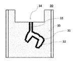
30 鋳型
31 空隙
32 耐熱性セラミックス粉末
33 スプルー線部
34 湯口部
35 埋没材の焼成体
A 歯科用補綴装置
11
23
以下、本発明を実施するための形態について説明するが、本発明は、下記の実施形態に制限されることはなく、本発明の範囲を逸脱することなく、下記の実施形態に種々の変形および置換を加えることができる。本実施形態ではワックスパターンの表面処理材の一構成例について説明する。 Hereinafter, embodiments for carrying out the present invention will be described, but the present invention is not limited to the following embodiments, and various modifications and variations to the following embodiments are made without departing from the scope of the present invention. Substitutions can be added. In this embodiment, a configuration example of a surface treatment material for a wax pattern will be described.
本発明をさらに詳細に説明する。
本発明のワックスパターンに塗布する表面処理材は、耐熱性セラミックス粉末を含むことが特徴である。これにより、この表面処理材を塗布したワックスパターンを用いて作製した鋳型にプレス成型したガラスセラッミクス表面への埋没材の焼き付きを低減することが可能となる。本発明の表面処理材は、ワックスパーターンに塗布することが特徴であり、仮に本発明の表面処理材を埋没材に混合させても同等の焼き付きを防止する効果や焼き付き物の視認性を得るのは困難である。
The present invention will be described in more detail.
The surface treatment material applied to the wax pattern of the present invention is characterized by containing heat-resistant ceramic powder. This makes it possible to reduce the seizure of the investment material on the surface of the glass ceramics press-molded on the mold produced by using the wax pattern coated with the surface treatment material. The surface treatment material of the present invention is characterized in that it is applied to a wax pattern, and even if the surface treatment material of the present invention is mixed with the investment material, the same effect of preventing seizure and visibility of the seized material can be obtained. It is difficult.
本発明の表面処理材に含まれる耐熱性セラミックス粉末は、炭化ケイ素、炭化ホウ素、炭化窒素、窒化ケイ素から選ばれた少なくとも1種類以上を含んでいることが好ましい。これらの中でも、炭化ケイ素または炭化ホウ素は、焼き付きを防ぐ効果が優れていること、また粉末自体が黒灰色であることよりガラスセラミックスとの色差が明確であることから、特に好ましい。最も好ましくは炭化ケイ素であり、優れた効果を示す。また、耐熱性セラミックス粉末の形状は特に制限はなく、球型や不定形であっても特に問題はない。さらに耐熱性セラミックス粉末の製造方法や破砕方法等にも制限はなくいづれの方法で製造したものでも用いることができる。 The heat-resistant ceramic powder contained in the surface treatment material of the present invention preferably contains at least one selected from silicon carbide, boron carbide, nitrogen carbide, and silicon nitride. Among these, silicon carbide or boron carbide is particularly preferable because it has an excellent effect of preventing seizure and the color difference from the glass ceramics is clearer than the powder itself being black-gray. Most preferably, it is silicon carbide, which exhibits excellent effects. Further, the shape of the heat-resistant ceramic powder is not particularly limited, and there is no particular problem even if it is spherical or irregular. Further, there are no restrictions on the method for producing the heat-resistant ceramic powder, the method for crushing the powder, and the like, and any method can be used.
本発明の表面処理材に含まれる耐熱性セラミックス粉末の平均粒度は特に制限はないものの、好ましくは0.1〜100μm、より好ましくは0.1〜50.0μmである。より好ましくは、0.1〜10μmである。平均粒度が0.1μm未満であると十分な離型効果が得難く、一方100μmよりも大きくなるといと塗布面の厚みが厚くなり、また均一な塗布層が得られず、プレス成型したガラスセラミックス表面に凹凸が生じやすくなり、審美性が不良になる恐れがある。本発明の表面処理材のワックスパターンへの塗布方法は特に制限はなく、上部からの散布、筆による塗布、粉状物中へのディッピング等、いずれの方法でも何等問題はない。その中でも本発明の表面処理材を直接筆にとりワックスパターンに軽く押し当てながら塗布することが好ましい。この方法であると余剰分の表面処理材はワックスパターンを逆さまに向けたり、また振動を与えたり、弱風をあてたりすることにより、容易に除去することができ、薄い均一な離型材層をワックスパターン上に形成することができる。また形成した離型材層は呼気程度の風では、剥離することはない程度にワックスパターン上で固着することができる。 The average particle size of the heat-resistant ceramic powder contained in the surface treatment material of the present invention is not particularly limited, but is preferably 0.1 to 100 μm, more preferably 0.1 to 50.0 μm. More preferably, it is 0.1 to 10 μm. If the average particle size is less than 0.1 μm, it is difficult to obtain a sufficient mold release effect, while if it is larger than 100 μm, the thickness of the coated surface becomes thick, and a uniform coated layer cannot be obtained. Irregularities are likely to occur on the surface, which may result in poor aesthetics. The method for applying the surface treatment material of the present invention to the wax pattern is not particularly limited, and there is no problem with any method such as spraying from above, applying with a brush, and dipping into powder. Among them, it is preferable to take the surface treatment material of the present invention directly with a brush and apply it while lightly pressing it against the wax pattern. With this method, the excess surface treatment material can be easily removed by turning the wax pattern upside down, applying vibration, or applying a weak wind to form a thin and uniform release material layer. It can be formed on a wax pattern. Further, the formed release material layer can be fixed on the wax pattern to the extent that it does not peel off in a wind of about exhalation.
さらに本発明の表面処理材をワックスパターンに塗布する操作性をさらに向上させるために、水、有機溶媒、レジン成分、有機天然物、増粘剤等を含んで粘性のある液状物又はクリーム状物、ペースト状物にすることもできる。しかし、これらの場合、粘性が高くなると塗布した膜厚が高くなりプレス形成したガラスセラミックスの最終形態を損なう恐れがあるため、薄く塗布できるぐらいの粘性にしておく必要がある。また、操作性をさらに向上させるために、あらかじめワックスパターンに、水、有機溶媒、レジン成分、有機天然物、増粘剤等を塗布しておき、その後表面処理材を塗布することもできる。また、これらの成分が揮発性のものであればワックスパターンへの塗布時に揮発するため問題はないが、揮発しないものであればワックスパターンを焼却して鋳型を作製する時にワックスパターンと共に蒸発するものでなければならず、あくまでも鋳型の内面には本発明の表面処理材に含まれる耐熱性セラミックス粉末のみが存在する状態でなければならない。耐熱性セラミックス粉末以外の成分は、歯科用補綴装置の変色や黒点の原因となる可能性があるものは含まないことが好ましく、より簡便な塗布作業を可能にするためには本発明の表面処理材は耐熱性セラミックス粉末のみを含んだ粉状物であることが好ましい態様である。 Further, in order to further improve the operability of applying the surface treatment material of the present invention to the wax pattern, a viscous liquid or cream containing water, an organic solvent, a resin component, an organic natural product, a thickener and the like. , Can also be made into a paste. However, in these cases, when the viscosity becomes high, the film thickness applied becomes high and the final form of the press-formed glass ceramics may be impaired. Therefore, it is necessary to make the viscosity so that it can be applied thinly. Further, in order to further improve the operability, water, an organic solvent, a resin component, an organic natural product, a thickener or the like may be applied to the wax pattern in advance, and then a surface treatment material may be applied. If these components are volatile, they will volatilize when applied to the wax pattern, so there is no problem, but if they are not volatile, they will evaporate together with the wax pattern when the wax pattern is incinerated to make a mold. It must be in a state where only the heat-resistant ceramic powder contained in the surface treatment material of the present invention is present on the inner surface of the mold. It is preferable that the components other than the heat-resistant ceramic powder do not contain components that may cause discoloration or black spots of the dental prosthesis device, and the surface treatment of the present invention is to enable a simpler coating operation. It is preferable that the material is a powdery material containing only heat-resistant ceramic powder.
ここで、本実施形態の歯科用補綴装置の製作方法の各工程について図 1、図 2、図3を用いながら以下に説明する。 Here, each step of the method of manufacturing the dental prosthesis device of the present embodiment will be described below with reference to FIGS. 1, 2, and 3.
図1、図2、図3は、本実施形態の歯科用補綴装置の製作方法の各工程を模式的に示したものである。 1, FIG. 2 and FIG. 3 schematically show each step of the method of manufacturing the dental prosthetic device of the present embodiment.
まず、本実施形態の歯科用補綴装置の製作方法を開始する前に、図1に示すように、形成する歯科用補綴装置Aに対応した形状を有するワックスパターン 11を準備することができる。
First, before starting the method for manufacturing the dental prosthesis device of the present embodiment, as shown in FIG. 1, a
ワックスパターン 11は埋没材中に埋没させ、該埋没材が硬化した後焼却することで、図3のように該埋没材中に歯科用補綴装置 Aに対応した形状の空隙を有する鋳型を形成し、該鋳型中の空隙にプレス成型によりガラスセラミックスを供給することで所望の形状の歯科用補綴装置 Aを形成することができる。そして、埋没材中に歯科用補綴装置 Aに対応した形状の空隙を形成する際、該空隙にプレス成型によりガラスセラミックスを供給するための供給路もあわせて形成できるように、ワックスパターン 11にはスプルー部 12を併せて形成しておくことが好ましい。
The
ワックスパターン 11は、形成する歯科用補綴装置 Aに対応した形状にできるように、例えば印象材等で取得した歯型に石膏を流して作製した石膏模型 13上に形成することができる。
The
ワックスパターン 11、及びそのスプルー部 12は共に歯科用のワックスにより形成されることが好ましい。
Both the
次に、ワックスパターン 11、及びそのスプルー部 12の表面に、本実施形態の表面処理材 21を塗布する工程を実施することができる。
Next, the step of applying the
ワックスパターンに表面処理材を塗布する工程はワックスパターン 11、及びそのスプルー部 12を台に固定して実施することが好ましい。例えば後述する埋没工程においてワックスパターン 11、及びそのスプルー部 12をプランジャーベース 22に固定することから、本工程でもプランジャーベース 22に固定して行うことができる。
The step of applying the surface treatment material to the wax pattern is preferably carried out by fixing the
そして、ゴムリング 23の内部にスラリー状にした埋没材 24 (鋳型材ともいう)を流し込んで、ワックスパターン 11、及びそのスプルー部 12を埋没させる。なお、図2中の表面処理材 21の存在が分かり易いように便宜的に大きな黒丸で記載しており、埋没後もワックスパターン表面に固着している。
Then, a slurry-like buried material 24 (also referred to as a mold material) is poured into the
埋没工程で用いる埋没材の種類は特に限定されるものではなく、ガラス系材料をプレス成型する温度、圧力に耐えられる材料であれば良い。例えばリン酸塩系の埋没材を好ましく用いることができる。 The type of the burying material used in the burying step is not particularly limited, and any material that can withstand the temperature and pressure for press-molding the glass-based material may be used. For example, a phosphate-based investment material can be preferably used.
そして、埋没材の硬化後に、ワックスパターンを含む埋没材を加熱してワックスパターンを焼却し、鋳型を作製する工程を実施することができる。 Then, after the investment material is cured, the process of heating the investment material containing the wax pattern to incinerate the wax pattern and producing a mold can be carried out.
埋没材が硬化した後、プランジャーベース 22、ゴムリング 23を取り外し、焼成することができる。この際の焼成温度は特に限定されるものではなく、ワックスパターン 11、及びそのスプルー部 12を形成する際に用いたワックスの材料や埋没材 24の材料に応じて温度を選択することができる。
After the investment material has hardened, the
鋳型を作製する工程を実施することにより図3に示すように、ワックスパターン 11が除去され、プレス成型する歯科用補綴装置 Aに対応した形状の空隙 31が形成されると共に、そのスプルー部 12も焼却されるため、該空隙 31に通じるスプルー線部 33が形成される。スプルー線部 33の一方の端部には、後述する成型工程でガラスインゴットを配置するための湯口部 34が形成されている。係る湯口部 34はスプルー線部 33を固定したプランジャーベース 22に対応した形状となっている。
As shown in FIG. 3, the
そして、空隙 31、及びスプルー線部 33の表面には、ワックスパターン 11の表面に塗布した本実施形態の表面処理材に含まれている耐熱性セラミックス粉末32が存在している状態とすることができる。なお、図中、耐熱性セラミックス粉末32の存在が分かり易いように便宜的に大きな黒丸で記載している。
Then, the heat-resistant
また、焼却工程を実施することで埋没材も焼成され、埋没材の焼成体 35とすることができ、該埋没材の焼成体 35中に形成する歯科用補綴装置に対応した形状の空隙 31を有する鋳型 30を形成することができる。
Further, by carrying out the incineration step, the buried material can also be fired to form a fired
次に、ガラスインゴットを焼却工程で形成した鋳型に鋳込むプレス成型工程を実施することができる。すなわち、プレス成型では、埋没材中のワックスパターンが焼却されることで形成された鋳型内の空隙に、ガラスインゴットを加熱、加圧して充填することができる。 Next, a press molding step of casting the glass ingot into the mold formed in the incineration step can be carried out. That is, in press molding, the glass ingot can be heated and pressurized to fill the voids in the mold formed by incineration of the wax pattern in the investment material.
具体的には、図3を用いて説明した鋳型 30の湯口部 34にガラスインゴットを置き、その上にアルミナプランジャ―を設置する。この状態でプレス機にセットし、加熱後プレス成型することで、空隙 31、及びスプルー線部 33にガラス成型体を充填することができる。
Specifically, a glass ingot is placed on the
成型終了後は鋳型からガラスセ成型体を堀り出し、図 1 記載のスプルー部12を切断することで、歯科用補綴装置 Aを得ることができる。
After the molding is completed, the dental prosthesis device A can be obtained by digging out the glass molded body from the mold and cutting the
以上に説明した本実施形態の歯科用補綴装置の製作方法によれば、ガラスインゴットをプレス成型して歯科用補綴装置を製作する際に、セラミックス製の歯科用補綴装置表面に荒れが生じることを抑制することができる。このため、従来よりも歩留まり良く歯科用補綴装置を製作することが可能になる。
According to the method for manufacturing the dental prosthesis device of the present embodiment described above, when the glass ingot is press-molded to manufacture the dental prosthesis device, the surface of the dental prosthesis device made of ceramics is roughened. It can be suppressed. Therefore, it becomes possible to manufacture a dental prosthesis device with a higher yield than before.
以下に、本発明を実施例によって説明するが本発明はこれら実施例に限定されるものではない。 Hereinafter, the present invention will be described by way of examples, but the present invention is not limited to these examples.
<歯科用補綴装置の作製試験>
(歯科用補綴装置の製作)
患者の歯から、シリコーンラバー印象材を用いて歯型を取った。次いで、その歯型に石膏を流し、石膏模型を形成した。次に、図1に示すように、石膏模型13上に歯科用ワックス(株式会社松風製 製品名:マイティーワックスソフト)を用いて、基準ワックスパターン11を形成した。基準ワックスパターン11が、複製できるように歯科用スキャナー(株式会社松風製 製品名松風S-WAVEスキャナー D2000)により基準ワックスパターン11のデータを読取った。次に基準ワックスパターン11のデータをデンタルCAMソフトウェアGO2dental(松風仕様)でNCデータへ変換し、ミリング装置(株式会社松風製 製品名DWX-50)で、ワックスディスク(松風ディスクワックス)から削りだし、歯形状のワックスパターン11を複数個作製した。
<Manufacturing test of dental prosthesis device>
(Manufacturing of dental prosthesis)
A tooth mold was taken from the patient's tooth using a silicone rubber impression material. Then, plaster was poured into the tooth mold to form a plaster model. Next, as shown in FIG. 1, a
そして、ワックスパターン11、及びそのスプルー部(株式会社松風製 製品名:松風キィワックスNo.8)12をプランジャーベース22上に接合した。そして、上述のワックスパターンの表面処理材21(炭化ケイ素 商品名株式会社フジミインコーポレーテッドGC10000、平均粒子径1μm )をワックスパターン11の表面、及びそのスプルー部12の表面に筆を用いて塗布した。
Then, the
次に、ワックスパターン11、及びそのスプルー部12を固定したプランジャーベース22の土台部の周縁部上に、ワックスパターン11、及びスプルー部12を囲むように、ゴムリング23を配置した。
Next, the
そして、図2に示すように、ゴムリング23の内部にスラリー状にした埋没材 24 (鋳型ともいう)を流し込んで、ワックスパターン11、及びそのスプルー部12を埋没させた。この際埋没材としては、リン酸塩系埋没材(株式会社松風製 製品名:セラベティP&C)を用いた。
Then, as shown in FIG. 2, a slurry-like buried material 24 (also referred to as a mold) was poured into the
埋没材が硬化するまで放置した後、プランジャーベース 22、ゴムリング 23を取り外し、ワックスパターン11を含む埋没材を大気雰囲気下、850℃で45分間加熱してワックスパターンを焼却して鋳型を形成した。図3に示すように、ワックスパターン11、及びそのスプルー部12が除去されていることが確認できた。
After leaving until the investment material hardens, remove the
そこで図3に示した鋳型30の湯口部34にガラスセラミックスである二ケイ酸リチウムのインゴットを置き、その上にアルミナプランジャ―を設置する。この状態でプレス成型機(株式会社松風 製品名エステマットプレス)の装置内にセットした。鋳型 30、及びインゴットを真空雰囲気下、925℃加熱しながら、インゴットをピストンによりプレス成型を行った。プレス成型を行うことで、図3に示すように鋳型30内のスプルー線部 33、及び空隙31にプレスガラスセラミックス成形体を充填した。冷却後、鋳型30からガラスセラミックス成型体を石膏鉗子、ガラスビーズによるサンドブラスト処理等によって取り出し、図1に示したスプルー部 12を切断することで歯科用補綴装置を得た。
Therefore, an ingot of lithium disilicate, which is a glass ceramic, is placed on the
上記方法で歯科用補綴装置を製作することで、簡便にガラスセラミックスの歯科用補綴装置を製作することができた。またそのガラスセラミックス表面にわずかに残存した焼き付き物も容易に識別することができ、サンドブラスト処理において完全に除去することができることが可能であった。
By manufacturing the dental prosthesis device by the above method, it was possible to easily manufacture the dental prosthesis device made of glass ceramics. Further, it was possible to easily identify the burn-in matter slightly remaining on the surface of the glass-ceramics, and it was possible to completely remove it by the sandblasting treatment.
<焼き付き性評価試験>
歯形状のワックスパターンの代わりに10mm×10mm 厚み1mmの平板のワックスパターンを用いた以外は歯科用補綴装置の作製試験と同様の方法でガラスセラミックス製平板を作製した。用いた表面処理材を以下に示す。なお、実施例で用いた株式会社松風 製品名ワックスクリーナースプレーは、主成分を水とする水性ワックスクリーナー材である。
実施例1 炭化ケイ素 (株式会社フジミインコーポレーテッドGC10000)
平均粒子径約1μm
実施例2 炭化ケイ素 (株式会社フジミインコーポレーテッドGC240)
平均粒子径約55μm
実施例3 炭化ホウ素 (和光純薬工業株式会社製) 平均粒子径約30μm
実施例4 窒化ホウ素 (デンカ株式会社製 窒化ホウ素GP 平均粒子径約
8μm)と水性ワックスクリーナー材(株式会社松風 製品名ワッ
クスクリーナースプレー)が3g:30gの混合物
実施例5 水性ワックスクリーナー材(株式会社松風 製品名ワックスクリーナースプレー)をワックスパターンに塗布し、液が乾燥しないうちに炭化ケイ素 (株式会社フジミインコーポレーテッドGC240)平均粒子径約55μmを筆で塗布したもの
実施例6 窒化ホウ素 (デンカ株式会社製 窒化ホウ素GP 平均粒子径約
8μm)
実施例7 窒化ホウ素 (MOMENTIVE社製 PT-350平均粒子径130μm )
実施例8 水性ワックスクリーナー材(株式会社松風 製品名ワックスクリーナースプレー)をワックスパターンに塗布し、液が乾燥しないうちに炭化ケイ素 (株式会社フジミインコーポレーテッドGC180)平均粒子径約80μmを筆で塗布したもの
比較例1 珪石(福島窯業株式会社製 製品名シリカパウダーC06-12
平均粒子径6μm)
比較例2 酸化アルミニウム(株式会社フジミインコーポレーテッドWA8000
平均粒子径1μm)
比較例3 表面処理材なし
<Burn-in evaluation test>
A glass ceramic flat plate was prepared in the same manner as the production test of the dental prosthetic device except that a flat wax pattern of 10 mm × 10 mm and a thickness of 1 mm was used instead of the tooth-shaped wax pattern. The surface treatment materials used are shown below. The product name Wax Cleaner Spray of SHOFU INC. Used in the examples is a water-based wax cleaner material containing water as the main component.
Example 1 Silicon Carbide (Fujimi Incorporated GC10000 Co., Ltd.)
Average particle size about 1 μm
Example 2 Silicon Carbide (Fujimi Incorporated GC240 Co., Ltd.)
Average particle size about 55 μm
Example 3 Boron Carbide (manufactured by Wako Pure Chemical Industries, Ltd.) Average particle size of about 30 μm
Example 4 Boron Nitride (Born Nitride GP, manufactured by Denka Corporation, average particle size approx.
8 μm) and water-based wax cleaner material (SHOFU INC. Product name Wat
Mixture of 3g: 30g of wax cleaner spray) Example 5 Aqueous wax cleaner material (Matsukaze Co., Ltd. product name wax cleaner spray) is applied to the wax pattern, and silicon carbide (Fujimi Incorporated GC240 Co., Ltd.) is applied before the liquid dries. An average particle size of about 55 μm applied with a brush
Example 6 Boron Nitride (Born Nitride GP, manufactured by Denka Corporation, average particle size approx.
8 μm)
Example 7 Boron Nitride (PT-350, manufactured by MOMENTIVE, average particle size 130 μm)
Example 8 A water-based wax cleaner material (Matsukaze Co., Ltd. product name Wax Cleaner Spray) was applied to the wax pattern, and silicon carbide (Fujimi Incorporated GC180 Co., Ltd.) with an average particle size of about 80 μm was applied with a brush before the liquid dried. Comparative example 1 Silica stone (manufactured by Fukushima Ceramics Co., Ltd. Product name Silica powder C06-12
Average particle size 6 μm)
Comparative Example 2 Aluminum Oxide (Fujimi Incorporated WA8000 Co., Ltd.)
Average particle size 1 μm)
Comparative Example 3 No surface treatment material
この平板に対して、プレス成型後(サンドブラスト処理前)、およびガラスビーズによるサンドブラスト処理(圧力は、0.4Mpa)を1分間行った後、その処理面に残存する焼き付き物の状態を顕微鏡により観察・評価した。
焼き付き性の評価は以下の基準に従って平板2個について行い、2個の平均で焼き付き物の付着が平板の半分以下の時を「合格」と判定した。結果を表1に示す。また、試験後の平板写真を図4〜図5に示す。
◎ :焼き付き物が全く確認されない
○ :焼き付き物がわずかに付着している(平板全体の25%以下)
△ :焼き付き物が平面全体の半分程度付着している
× :焼き付き物がほぼ平面全体に付着している(平板全体の75%以上)
×× :焼き付き物が平板全体に付着している
After press molding (before sandblasting) and sandblasting with glass beads (pressure is 0.4Mpa) for 1 minute on this flat plate, the state of the seized material remaining on the treated surface is observed with a microscope. evaluated.
The seizure property was evaluated for two flat plates according to the following criteria, and when the average adhesion of the two flat plates was less than half of the flat plates, it was judged as "pass". The results are shown in Table 1. Further, the flat plate photographs after the test are shown in FIGS. 4 to 5.
◎: No burn-in is confirmed ○: Slightly burn-in is attached (25% or less of the entire flat plate)
Δ: About half of the entire flat surface has burn-in. ×: The burn-in has adhered to almost the entire flat surface (75% or more of the entire flat surface).
XX: Burn-in is attached to the entire flat plate

焼き付き性評価試験結果について、以下に示す。
・実施例1(炭化ケイ素 平均粒子径約1μm)では、表面処理材の塗布を均一に行うことが可能であり、塗布性は非常に良好であった。また、ガラスセラミックス表面への焼き付きはほとんどなく、わずかに残存した焼き付き物も色差により容易に識別することができるため、サンドブラスト処理において完全に除去することが可能であった。
・実施例2(炭化ケイ素 平均粒子径約55μm)では、表面処理材の塗布性も問題なく、ガラスセラミックス表面の焼き付きもわずかであった。残存した焼き付き物も色差により容易に識別することができるため、サンドブラスト処理においてほとんど除去することが可能であった。
・実施例3(炭化ホウ素 平均粒子径約30μm)では、表面処理材の塗布は問題なく行えた。ガラスセラミックス表面の焼き付きが生じている部分があり残存した焼き付き物も色差により容易に識別することができるため、サンドブラスト処理である程度除去することが可能であった。
・実施例4(窒化ホウ素8μmと水性ワックスクリーナーが3g:30gの混合物)では、表面処理材の塗布時にムラになる部分があった。ガラスセラミックス表面に焼き付きが生じている部分があり、残存した焼き付き物は、ガラスセラミックスと類似の色調であったが、サンドブラスト処理である程度除去することが可能であった。
・実施例5 水性ワックスクリーナー材をワックスパターンに塗布し、液が乾燥しないうちに炭化ケイ素平均粒子径約55μmを筆で塗布したものでは、表面処理材の塗布は問題なく行えた。ガラスセラミックス表面の焼き付きがわずかにあったものの、残存した焼き付き物も色差により容易に識別することができるため、サンドブラスト処理においてほとんど除去することが可能であった。
・実施例6(窒化ホウ素 平均粒子径約8μm)では、表面処理材の塗布は問題なく行えた。ガラスセラミックス表面の焼き付きが生じている部分があり、残存した焼き付き物は、ガラスセラミックスと類似の色調であったが、サンドブラスト処理である程度除去することが可能であった。
・実施例7(窒化ホウ素 平均粒子径130μm )では、表面処理材の塗布面が厚くなる傾向があったが、問題なく塗布が可能であった。ガラスセラミックス表面の焼き付きが生じている部分があり、残存した焼き付き物は、ガラスセラミックスと類似の色調であったが、サンドブラスト処理である程度除去することが可能であった。
・実施例8 水性ワックスクリーナー材をワックスパターンに塗布し、液が乾燥しないうちに炭化ケイ素 平均粒子径約80μmを筆で塗布したものでは、表面処理材の塗布面が厚くなる傾向があったが、問題なく行えた。ガラスセラミックス表面の焼き付きがわずかにあったものの、残存した焼き付き物も色差により容易に識別することができるため、サンドブラスト処理においてほとんど除去することが可能であった。
・比較例1(珪石 平均粒子径6μm)では、塗布時にムラになる部分があった。ガラスセラミックス表面で焼き付きが起こり、焼き付き物はサンドブラスト処理で除去することが困難であった。
・比較例2(酸化アルミニウム 平均粒子径1μm)では、塗布は問題なく行えたものの、ガラスセラミックス表面で焼き付きが起こり、焼き付き物はサンドブラスト処理で除去することが困難であった。
・比較例3では、ガラスセラミックス表面全体で焼き付きが起こり、焼き付き物はサンドブラスト処理で除去することがほとんどできなかった。
The results of the seizure evaluation test are shown below.
-In Example 1 (silicon carbide average particle diameter of about 1 μm), the surface treatment material could be uniformly applied, and the coatability was very good. In addition, there was almost no seizure on the surface of the glass-ceramics, and a slight amount of residual seized material could be easily identified by the color difference, so that it could be completely removed by the sandblasting treatment.
-In Example 2 (silicon carbide average particle diameter of about 55 μm), there was no problem in the coatability of the surface treatment material, and the seizure on the surface of the glass ceramic was slight. Since the remaining burn-in matter can be easily identified by the color difference, it was possible to almost remove it in the sandblasting treatment.
-In Example 3 (boron carbide average particle size of about 30 μm), the surface treatment material could be applied without any problem. Since there is a part where the surface of the glass ceramic is seized and the remaining seized material can be easily identified by the color difference, it was possible to remove it to some extent by sandblasting.
-In Example 4 (a mixture of 8 μm boron nitride and 3 g: 30 g of water-based wax cleaner), there was a portion that became uneven when the surface treatment material was applied. There was a part where seizure occurred on the surface of the glass ceramic, and the remaining seized product had a color tone similar to that of the glass ceramic, but it could be removed to some extent by sandblasting.
-Example 5 When the water-based wax cleaner material was applied to the wax pattern and the average particle size of silicon carbide of about 55 μm was applied with a brush before the liquid was dried, the surface treatment material could be applied without any problem. Although the surface of the glass-ceramics was slightly seized, the remaining seized material could be easily identified by the color difference, so that it could be almost removed by the sandblasting treatment.
-In Example 6 (boron nitride average particle size of about 8 μm), the surface treatment material could be applied without any problem. There was a part where the surface of the glass ceramic was seized, and the remaining seized product had a color tone similar to that of the glass ceramic, but it could be removed to some extent by sandblasting.
-In Example 7 (boron nitride average particle size 130 μm), the coated surface of the surface treatment material tended to be thick, but the coating was possible without any problem. There was a part where the surface of the glass ceramic was seized, and the remaining seized product had a color tone similar to that of the glass ceramic, but it could be removed to some extent by sandblasting.
Example 8 When a water-based wax cleaner was applied to the wax pattern and the average particle size of silicon carbide of about 80 μm was applied with a brush before the liquid was dried, the coated surface of the surface treatment material tended to be thick. I was able to do it without any problems. Although the surface of the glass-ceramics was slightly seized, the remaining seized material could be easily identified by the color difference, so that it could be almost removed by the sandblasting treatment.
-In Comparative Example 1 (silica stone average particle size 6 μm), there was a portion that became uneven during coating. Seizure occurred on the surface of the glass-ceramics, and it was difficult to remove the seized matter by sandblasting.
-In Comparative Example 2 (aluminum oxide average particle size 1 μm), although the coating could be performed without any problem, seizure occurred on the surface of the glass ceramic, and it was difficult to remove the seized product by sandblasting.
-In Comparative Example 3, seizure occurred on the entire surface of the glass-ceramics, and the seized matter could hardly be removed by sandblasting.
以上にワックスパターンの表面処理材、歯科用補綴装置の製作方法を、実施形態、実施例等で説明したが、本発明は上記実施形態、実施例等に限定されない。特許請求の範囲に記載された本発明の要旨の範囲内において、種々の変形、変更が可能である。 Although the method for manufacturing the wax pattern surface treatment material and the dental prosthesis device has been described above in the embodiments, examples, etc., the present invention is not limited to the above-described embodiments, examples, and the like. Various modifications and changes are possible within the scope of the gist of the present invention described in the claims.
耐熱性セラミックスを含むワックスパターンの表面処理材を歯科用プレスセラミックスの鋳造時に使用することにより、効率よく所望する歯科用補綴装置を得る方法である。すなわち、プレスセラミックスの鋳造において、ワックスパターンの表面処理材を筆でワックスパターンの表面全体に塗布することにより、鋳造時の鋳型とプレス成型したガラスセラミックスとの焼き付きを抑制するだけでなく、鋳造後のサンドブラストや研磨の際にも表面処理材の確認が容易で、確実に取り除くことが出来る。その結果、効率よく所望する歯科用補綴装置を得ることが出来る。
This is a method for efficiently obtaining a desired dental prosthesis device by using a wax pattern surface treatment material containing heat-resistant ceramics at the time of casting dental press ceramics. That is, in the casting of pressed ceramics, by applying the surface treatment material of the wax pattern to the entire surface of the wax pattern with a brush, not only the seizure between the mold and the press-molded glass ceramics during casting is suppressed, but also after casting. It is easy to check the surface treatment material even during sandblasting and polishing, and it can be removed reliably. As a result, the desired dental prosthesis device can be efficiently obtained.
Claims (2)
炭化ケイ素粉末を含む表面処理材をワックスパターンの表面に塗布する工程、The process of applying a surface treatment material containing silicon carbide powder to the surface of a wax pattern,
前記ワックスパターンをりん酸塩系埋没材に埋没・硬化させる工程、A step of burying and curing the wax pattern in a phosphate-based investment material,
前記埋没材を加熱して前記ワックスパターンを焼却して鋳型を作製する工程、A step of heating the investment material and incinerating the wax pattern to prepare a mold.
ガラスインゴットを加熱して前記鋳型に圧入するプレス成型工程、A press molding process in which a glass ingot is heated and press-fitted into the mold.
を含むことを特徴とする歯科用プレスセラミックスの製作方法。A method for producing dental pressed ceramics, which comprises.
炭化ケイ素粉末をワックスパターンに塗布する工程、The process of applying silicon carbide powder to a wax pattern,
前記ワックスパターンをりん酸塩系埋没材に埋没・硬化させる工程、A step of burying and curing the wax pattern in a phosphate-based investment material,
前記埋没材を加熱して前記ワックスパターンを焼却して鋳型を作製する工程、A step of heating the investment material and incinerating the wax pattern to prepare a mold.
ガラスインゴットを加熱して前記鋳型に圧入するプレス成型工程、A press molding process in which a glass ingot is heated and press-fitted into the mold.
を含むことを特徴とする歯科用プレスセラミックスの製作方法。A method for producing dental pressed ceramics, which comprises.
Priority Applications (1)
| Application Number | Priority Date | Filing Date | Title |
|---|---|---|---|
| JP2017070080A JP6855121B2 (en) | 2017-03-31 | 2017-03-31 | Wax pattern surface treatment material used in combination with phosphate-based investment material and method for manufacturing dental pressed ceramics using it |
Applications Claiming Priority (1)
| Application Number | Priority Date | Filing Date | Title |
|---|---|---|---|
| JP2017070080A JP6855121B2 (en) | 2017-03-31 | 2017-03-31 | Wax pattern surface treatment material used in combination with phosphate-based investment material and method for manufacturing dental pressed ceramics using it |
Publications (2)
| Publication Number | Publication Date |
|---|---|
| JP2018171173A JP2018171173A (en) | 2018-11-08 |
| JP6855121B2 true JP6855121B2 (en) | 2021-04-07 |
Family
ID=64106870
Family Applications (1)
| Application Number | Title | Priority Date | Filing Date |
|---|---|---|---|
| JP2017070080A Active JP6855121B2 (en) | 2017-03-31 | 2017-03-31 | Wax pattern surface treatment material used in combination with phosphate-based investment material and method for manufacturing dental pressed ceramics using it |
Country Status (1)
| Country | Link |
|---|---|
| JP (1) | JP6855121B2 (en) |
Family Cites Families (5)
| Publication number | Priority date | Publication date | Assignee | Title |
|---|---|---|---|---|
| JPS62204741A (en) * | 1985-11-21 | 1987-09-09 | オリンパス光学工業株式会社 | Dental casting mold and its production |
| JPH04356341A (en) * | 1991-05-31 | 1992-12-10 | Kyocera Corp | Centrifugal casting crucible |
| JP2652781B2 (en) * | 1994-11-30 | 1997-09-10 | ティーディーケイ株式会社 | Glass materials, biological tissue substitutes and orthodontics |
| JPH11285506A (en) * | 1998-02-05 | 1999-10-19 | Tokuyama Corp | Manufacture of ceramic tooth crown |
| US20170304034A1 (en) * | 2014-11-27 | 2017-10-26 | Gc Corporation | Surface treatment agent for wax pattern and method of manufacturing dental prosthesis |
-
2017
- 2017-03-31 JP JP2017070080A patent/JP6855121B2/en active Active
Also Published As
| Publication number | Publication date |
|---|---|
| JP2018171173A (en) | 2018-11-08 |
Similar Documents
| Publication | Publication Date | Title |
|---|---|---|
| US6739959B2 (en) | Assembly for the manufacture of medical, dental-medical, dental-technical and technical parts from ceramics | |
| JPH11502733A (en) | Preparation method of tooth restoration prosthesis | |
| JP2004532062A (en) | Dental model expansion material | |
| US11534279B2 (en) | Method for producing dentures | |
| JP2000313674A (en) | Ceramic material, base for dental restoration and dental restoration | |
| JP2014502603A (en) | Manufacturing of dental molded parts | |
| JP2019111407A (en) | Wax pattern surface treatment agent, and method for producing dental prosthesis | |
| US6361721B1 (en) | Method of forming tooth restoration | |
| JP2003047622A (en) | Dental ceramic frame, manufacture for it and dental prosthesis including the frame | |
| JP2009501595A (en) | Dental prosthesis | |
| JPH0234615B2 (en) | ||
| BRPI0412344A (en) | dental prosthesis manufacturing method, dental porcelain kit and set | |
| EP0993422B1 (en) | Dental restorations | |
| US6450813B1 (en) | Repair porcelain product, composition and method | |
| JP6855121B2 (en) | Wax pattern surface treatment material used in combination with phosphate-based investment material and method for manufacturing dental pressed ceramics using it | |
| KR20150003382A (en) | Gypsum-based embedding material composition for casting | |
| WO2013109491A1 (en) | Investment composition material having a reducing agent | |
| CN108938112B (en) | Phosphate-based embedding material for dental use | |
| JP2007190087A (en) | Method for producing tooth-crown prosthesis | |
| JP6605119B2 (en) | Wax pattern surface treatment agent | |
| US20030226475A1 (en) | Material for forming porcelain tooth restorations | |
| JP6706272B2 (en) | Dental investment material | |
| JPS62204741A (en) | Dental casting mold and its production | |
| WO1994004092A1 (en) | Improvements in or relating to substructures for bonding to support structures | |
| JPS63310737A (en) | Mold material for molding |
Legal Events
| Date | Code | Title | Description |
|---|---|---|---|
| A621 | Written request for application examination |
Free format text: JAPANESE INTERMEDIATE CODE: A621 Effective date: 20200227 |
|
| A977 | Report on retrieval |
Free format text: JAPANESE INTERMEDIATE CODE: A971007 Effective date: 20201124 |
|
| A131 | Notification of reasons for refusal |
Free format text: JAPANESE INTERMEDIATE CODE: A131 Effective date: 20201211 |
|
| A521 | Request for written amendment filed |
Free format text: JAPANESE INTERMEDIATE CODE: A523 Effective date: 20210122 |
|
| TRDD | Decision of grant or rejection written | ||
| A01 | Written decision to grant a patent or to grant a registration (utility model) |
Free format text: JAPANESE INTERMEDIATE CODE: A01 Effective date: 20210316 |
|
| A61 | First payment of annual fees (during grant procedure) |
Free format text: JAPANESE INTERMEDIATE CODE: A61 Effective date: 20210316 |
|
| R150 | Certificate of patent or registration of utility model |
Ref document number: 6855121 Country of ref document: JP Free format text: JAPANESE INTERMEDIATE CODE: R150 |
|
| R250 | Receipt of annual fees |
Free format text: JAPANESE INTERMEDIATE CODE: R250 |