JP6854805B2 - Hybrid PET / CT imaging detector - Google Patents
Hybrid PET / CT imaging detector Download PDFInfo
- Publication number
- JP6854805B2 JP6854805B2 JP2018506302A JP2018506302A JP6854805B2 JP 6854805 B2 JP6854805 B2 JP 6854805B2 JP 2018506302 A JP2018506302 A JP 2018506302A JP 2018506302 A JP2018506302 A JP 2018506302A JP 6854805 B2 JP6854805 B2 JP 6854805B2
- Authority
- JP
- Japan
- Prior art keywords
- layer
- energy
- pet
- detected
- gamma radiation
- Prior art date
- Legal status (The legal status is an assumption and is not a legal conclusion. Google has not performed a legal analysis and makes no representation as to the accuracy of the status listed.)
- Active
Links
- 238000013170 computed tomography imaging Methods 0.000 title description 8
- 238000012879 PET imaging Methods 0.000 title description 4
- 230000005855 radiation Effects 0.000 claims description 108
- 238000002591 computed tomography Methods 0.000 claims description 77
- 238000003384 imaging method Methods 0.000 claims description 53
- 239000000463 material Substances 0.000 claims description 34
- 238000006243 chemical reaction Methods 0.000 claims description 21
- 238000007689 inspection Methods 0.000 claims description 20
- 238000000034 method Methods 0.000 claims description 19
- 230000004044 response Effects 0.000 claims description 12
- 239000002096 quantum dot Substances 0.000 claims description 9
- 230000008569 process Effects 0.000 claims description 6
- XUIMIQQOPSSXEZ-UHFFFAOYSA-N Silicon Chemical compound [Si] XUIMIQQOPSSXEZ-UHFFFAOYSA-N 0.000 claims description 3
- 229910052710 silicon Inorganic materials 0.000 claims description 3
- 239000010703 silicon Substances 0.000 claims description 3
- 238000003325 tomography Methods 0.000 claims description 2
- QWUZMTJBRUASOW-UHFFFAOYSA-N cadmium tellanylidenezinc Chemical compound [Zn].[Cd].[Te] QWUZMTJBRUASOW-UHFFFAOYSA-N 0.000 claims 1
- 230000035945 sensitivity Effects 0.000 claims 1
- 239000010410 layer Substances 0.000 description 107
- 238000002600 positron emission tomography Methods 0.000 description 76
- 230000004048 modification Effects 0.000 description 6
- 238000012986 modification Methods 0.000 description 6
- 238000005538 encapsulation Methods 0.000 description 3
- 238000007781 pre-processing Methods 0.000 description 3
- MARUHZGHZWCEQU-UHFFFAOYSA-N 5-phenyl-2h-tetrazole Chemical compound C1=CC=CC=C1C1=NNN=N1 MARUHZGHZWCEQU-UHFFFAOYSA-N 0.000 description 2
- HCHKCACWOHOZIP-UHFFFAOYSA-N Zinc Chemical compound [Zn] HCHKCACWOHOZIP-UHFFFAOYSA-N 0.000 description 2
- MCVAAHQLXUXWLC-UHFFFAOYSA-N [O-2].[O-2].[S-2].[Gd+3].[Gd+3] Chemical compound [O-2].[O-2].[S-2].[Gd+3].[Gd+3] MCVAAHQLXUXWLC-UHFFFAOYSA-N 0.000 description 2
- ORCSMBGZHYTXOV-UHFFFAOYSA-N bismuth;germanium;dodecahydrate Chemical compound O.O.O.O.O.O.O.O.O.O.O.O.[Ge].[Ge].[Ge].[Bi].[Bi].[Bi].[Bi] ORCSMBGZHYTXOV-UHFFFAOYSA-N 0.000 description 2
- 230000005251 gamma ray Effects 0.000 description 2
- 238000004519 manufacturing process Methods 0.000 description 2
- 239000002245 particle Substances 0.000 description 2
- 239000007787 solid Substances 0.000 description 2
- 229910052725 zinc Inorganic materials 0.000 description 2
- 239000011701 zinc Substances 0.000 description 2
- ANDNPYOOQLLLIU-UHFFFAOYSA-N [Y].[Lu] Chemical compound [Y].[Lu] ANDNPYOOQLLLIU-UHFFFAOYSA-N 0.000 description 1
- 239000011358 absorbing material Substances 0.000 description 1
- 238000010521 absorption reaction Methods 0.000 description 1
- 230000003213 activating effect Effects 0.000 description 1
- 230000004913 activation Effects 0.000 description 1
- 210000003484 anatomy Anatomy 0.000 description 1
- 230000002238 attenuated effect Effects 0.000 description 1
- 230000001419 dependent effect Effects 0.000 description 1
- 239000003814 drug Substances 0.000 description 1
- 229940079593 drug Drugs 0.000 description 1
- 230000000694 effects Effects 0.000 description 1
- 239000002223 garnet Substances 0.000 description 1
- 230000003993 interaction Effects 0.000 description 1
- 230000005258 radioactive decay Effects 0.000 description 1
- 230000000284 resting effect Effects 0.000 description 1
- 239000002356 single layer Substances 0.000 description 1
- 230000003595 spectral effect Effects 0.000 description 1
- 238000001228 spectrum Methods 0.000 description 1
- 230000002269 spontaneous effect Effects 0.000 description 1
- WFKWXMTUELFFGS-UHFFFAOYSA-N tungsten Chemical compound [W] WFKWXMTUELFFGS-UHFFFAOYSA-N 0.000 description 1
- 229910052721 tungsten Inorganic materials 0.000 description 1
- 239000010937 tungsten Substances 0.000 description 1
Images


Classifications
-
- A—HUMAN NECESSITIES
- A61—MEDICAL OR VETERINARY SCIENCE; HYGIENE
- A61B—DIAGNOSIS; SURGERY; IDENTIFICATION
- A61B6/00—Apparatus or devices for radiation diagnosis; Apparatus or devices for radiation diagnosis combined with radiation therapy equipment
- A61B6/42—Arrangements for detecting radiation specially adapted for radiation diagnosis
- A61B6/4275—Arrangements for detecting radiation specially adapted for radiation diagnosis using a detector unit almost surrounding the patient, e.g. more than 180°
-
- G—PHYSICS
- G01—MEASURING; TESTING
- G01T—MEASUREMENT OF NUCLEAR OR X-RADIATION
- G01T1/00—Measuring X-radiation, gamma radiation, corpuscular radiation, or cosmic radiation
- G01T1/16—Measuring radiation intensity
- G01T1/161—Applications in the field of nuclear medicine, e.g. in vivo counting
- G01T1/1615—Applications in the field of nuclear medicine, e.g. in vivo counting using both transmission and emission sources simultaneously
- G01T1/1617—Applications in the field of nuclear medicine, e.g. in vivo counting using both transmission and emission sources simultaneously with scintillation detectors
-
- A—HUMAN NECESSITIES
- A61—MEDICAL OR VETERINARY SCIENCE; HYGIENE
- A61B—DIAGNOSIS; SURGERY; IDENTIFICATION
- A61B6/00—Apparatus or devices for radiation diagnosis; Apparatus or devices for radiation diagnosis combined with radiation therapy equipment
- A61B6/02—Arrangements for diagnosis sequentially in different planes; Stereoscopic radiation diagnosis
- A61B6/03—Computed tomography [CT]
- A61B6/032—Transmission computed tomography [CT]
-
- A—HUMAN NECESSITIES
- A61—MEDICAL OR VETERINARY SCIENCE; HYGIENE
- A61B—DIAGNOSIS; SURGERY; IDENTIFICATION
- A61B6/00—Apparatus or devices for radiation diagnosis; Apparatus or devices for radiation diagnosis combined with radiation therapy equipment
- A61B6/02—Arrangements for diagnosis sequentially in different planes; Stereoscopic radiation diagnosis
- A61B6/03—Computed tomography [CT]
- A61B6/037—Emission tomography
-
- A—HUMAN NECESSITIES
- A61—MEDICAL OR VETERINARY SCIENCE; HYGIENE
- A61B—DIAGNOSIS; SURGERY; IDENTIFICATION
- A61B6/00—Apparatus or devices for radiation diagnosis; Apparatus or devices for radiation diagnosis combined with radiation therapy equipment
- A61B6/42—Arrangements for detecting radiation specially adapted for radiation diagnosis
- A61B6/4208—Arrangements for detecting radiation specially adapted for radiation diagnosis characterised by using a particular type of detector
- A61B6/4233—Arrangements for detecting radiation specially adapted for radiation diagnosis characterised by using a particular type of detector using matrix detectors
-
- A—HUMAN NECESSITIES
- A61—MEDICAL OR VETERINARY SCIENCE; HYGIENE
- A61B—DIAGNOSIS; SURGERY; IDENTIFICATION
- A61B6/00—Apparatus or devices for radiation diagnosis; Apparatus or devices for radiation diagnosis combined with radiation therapy equipment
- A61B6/42—Arrangements for detecting radiation specially adapted for radiation diagnosis
- A61B6/4208—Arrangements for detecting radiation specially adapted for radiation diagnosis characterised by using a particular type of detector
- A61B6/4241—Arrangements for detecting radiation specially adapted for radiation diagnosis characterised by using a particular type of detector using energy resolving detectors, e.g. photon counting
-
- A—HUMAN NECESSITIES
- A61—MEDICAL OR VETERINARY SCIENCE; HYGIENE
- A61B—DIAGNOSIS; SURGERY; IDENTIFICATION
- A61B6/00—Apparatus or devices for radiation diagnosis; Apparatus or devices for radiation diagnosis combined with radiation therapy equipment
- A61B6/42—Arrangements for detecting radiation specially adapted for radiation diagnosis
- A61B6/4266—Arrangements for detecting radiation specially adapted for radiation diagnosis characterised by using a plurality of detector units
-
- A—HUMAN NECESSITIES
- A61—MEDICAL OR VETERINARY SCIENCE; HYGIENE
- A61B—DIAGNOSIS; SURGERY; IDENTIFICATION
- A61B6/00—Apparatus or devices for radiation diagnosis; Apparatus or devices for radiation diagnosis combined with radiation therapy equipment
- A61B6/42—Arrangements for detecting radiation specially adapted for radiation diagnosis
- A61B6/4291—Arrangements for detecting radiation specially adapted for radiation diagnosis the detector being combined with a grid or grating
-
- A—HUMAN NECESSITIES
- A61—MEDICAL OR VETERINARY SCIENCE; HYGIENE
- A61B—DIAGNOSIS; SURGERY; IDENTIFICATION
- A61B6/00—Apparatus or devices for radiation diagnosis; Apparatus or devices for radiation diagnosis combined with radiation therapy equipment
- A61B6/44—Constructional features of apparatus for radiation diagnosis
- A61B6/4417—Constructional features of apparatus for radiation diagnosis related to combined acquisition of different diagnostic modalities
-
- A—HUMAN NECESSITIES
- A61—MEDICAL OR VETERINARY SCIENCE; HYGIENE
- A61B—DIAGNOSIS; SURGERY; IDENTIFICATION
- A61B6/00—Apparatus or devices for radiation diagnosis; Apparatus or devices for radiation diagnosis combined with radiation therapy equipment
- A61B6/48—Diagnostic techniques
- A61B6/482—Diagnostic techniques involving multiple energy imaging
-
- A—HUMAN NECESSITIES
- A61—MEDICAL OR VETERINARY SCIENCE; HYGIENE
- A61B—DIAGNOSIS; SURGERY; IDENTIFICATION
- A61B6/00—Apparatus or devices for radiation diagnosis; Apparatus or devices for radiation diagnosis combined with radiation therapy equipment
- A61B6/52—Devices using data or image processing specially adapted for radiation diagnosis
- A61B6/5205—Devices using data or image processing specially adapted for radiation diagnosis involving processing of raw data to produce diagnostic data
-
- A—HUMAN NECESSITIES
- A61—MEDICAL OR VETERINARY SCIENCE; HYGIENE
- A61B—DIAGNOSIS; SURGERY; IDENTIFICATION
- A61B6/00—Apparatus or devices for radiation diagnosis; Apparatus or devices for radiation diagnosis combined with radiation therapy equipment
- A61B6/52—Devices using data or image processing specially adapted for radiation diagnosis
- A61B6/5211—Devices using data or image processing specially adapted for radiation diagnosis involving processing of medical diagnostic data
- A61B6/5229—Devices using data or image processing specially adapted for radiation diagnosis involving processing of medical diagnostic data combining image data of a patient, e.g. combining a functional image with an anatomical image
- A61B6/5235—Devices using data or image processing specially adapted for radiation diagnosis involving processing of medical diagnostic data combining image data of a patient, e.g. combining a functional image with an anatomical image combining images from the same or different ionising radiation imaging techniques, e.g. PET and CT
-
- A—HUMAN NECESSITIES
- A61—MEDICAL OR VETERINARY SCIENCE; HYGIENE
- A61B—DIAGNOSIS; SURGERY; IDENTIFICATION
- A61B6/00—Apparatus or devices for radiation diagnosis; Apparatus or devices for radiation diagnosis combined with radiation therapy equipment
- A61B6/52—Devices using data or image processing specially adapted for radiation diagnosis
- A61B6/5258—Devices using data or image processing specially adapted for radiation diagnosis involving detection or reduction of artifacts or noise
- A61B6/5282—Devices using data or image processing specially adapted for radiation diagnosis involving detection or reduction of artifacts or noise due to scatter
-
- G—PHYSICS
- G01—MEASURING; TESTING
- G01T—MEASUREMENT OF NUCLEAR OR X-RADIATION
- G01T1/00—Measuring X-radiation, gamma radiation, corpuscular radiation, or cosmic radiation
- G01T1/16—Measuring radiation intensity
- G01T1/1603—Measuring radiation intensity with a combination of at least two different types of detector
-
- G—PHYSICS
- G01—MEASURING; TESTING
- G01T—MEASUREMENT OF NUCLEAR OR X-RADIATION
- G01T1/00—Measuring X-radiation, gamma radiation, corpuscular radiation, or cosmic radiation
- G01T1/16—Measuring radiation intensity
- G01T1/161—Applications in the field of nuclear medicine, e.g. in vivo counting
- G01T1/1615—Applications in the field of nuclear medicine, e.g. in vivo counting using both transmission and emission sources simultaneously
-
- G—PHYSICS
- G01—MEASURING; TESTING
- G01T—MEASUREMENT OF NUCLEAR OR X-RADIATION
- G01T1/00—Measuring X-radiation, gamma radiation, corpuscular radiation, or cosmic radiation
- G01T1/16—Measuring radiation intensity
- G01T1/161—Applications in the field of nuclear medicine, e.g. in vivo counting
- G01T1/164—Scintigraphy
-
- G—PHYSICS
- G01—MEASURING; TESTING
- G01T—MEASUREMENT OF NUCLEAR OR X-RADIATION
- G01T1/00—Measuring X-radiation, gamma radiation, corpuscular radiation, or cosmic radiation
- G01T1/16—Measuring radiation intensity
- G01T1/20—Measuring radiation intensity with scintillation detectors
- G01T1/2008—Measuring radiation intensity with scintillation detectors using a combination of different types of scintillation detectors, e.g. phoswich
-
- G—PHYSICS
- G01—MEASURING; TESTING
- G01T—MEASUREMENT OF NUCLEAR OR X-RADIATION
- G01T1/00—Measuring X-radiation, gamma radiation, corpuscular radiation, or cosmic radiation
- G01T1/29—Measurement performed on radiation beams, e.g. position or section of the beam; Measurement of spatial distribution of radiation
- G01T1/2914—Measurement of spatial distribution of radiation
- G01T1/2985—In depth localisation, e.g. using positron emitters; Tomographic imaging (longitudinal and transverse section imaging; apparatus for radiation diagnosis sequentially in different planes, steroscopic radiation diagnosis)
-
- A—HUMAN NECESSITIES
- A61—MEDICAL OR VETERINARY SCIENCE; HYGIENE
- A61B—DIAGNOSIS; SURGERY; IDENTIFICATION
- A61B6/00—Apparatus or devices for radiation diagnosis; Apparatus or devices for radiation diagnosis combined with radiation therapy equipment
- A61B6/42—Arrangements for detecting radiation specially adapted for radiation diagnosis
- A61B6/4208—Arrangements for detecting radiation specially adapted for radiation diagnosis characterised by using a particular type of detector
- A61B6/4258—Arrangements for detecting radiation specially adapted for radiation diagnosis characterised by using a particular type of detector for detecting non x-ray radiation, e.g. gamma radiation
Landscapes
- Health & Medical Sciences (AREA)
- Life Sciences & Earth Sciences (AREA)
- Engineering & Computer Science (AREA)
- Medical Informatics (AREA)
- Physics & Mathematics (AREA)
- High Energy & Nuclear Physics (AREA)
- Molecular Biology (AREA)
- Nuclear Medicine, Radiotherapy & Molecular Imaging (AREA)
- General Health & Medical Sciences (AREA)
- Biomedical Technology (AREA)
- Optics & Photonics (AREA)
- Radiology & Medical Imaging (AREA)
- Public Health (AREA)
- Pathology (AREA)
- Veterinary Medicine (AREA)
- Biophysics (AREA)
- Heart & Thoracic Surgery (AREA)
- Surgery (AREA)
- Animal Behavior & Ethology (AREA)
- General Physics & Mathematics (AREA)
- Spectroscopy & Molecular Physics (AREA)
- Computer Vision & Pattern Recognition (AREA)
- Pulmonology (AREA)
- Theoretical Computer Science (AREA)
- Mathematical Physics (AREA)
- Nuclear Medicine (AREA)
- Apparatus For Radiation Diagnosis (AREA)
- Measurement Of Radiation (AREA)
Description
本発明は、概して、イメージング検出器に関し、特に、イメージング検出器によりガンマ線及びX線の両方を検出するように構成されるハイブリッドポジトロンエミッション(PET)/コンピュータトモグラフィ(CT)イメージング検出器に関する。 The present invention relates generally to imaging detectors, and in particular to hybrid positron emission (PET) / computed tomography (CT) imaging detectors that are configured to detect both gamma and X-rays by the imaging detector.
ポジトロンエミッショントモグラフィ(PET)イメージングは、身体に注入される放射性同位元素の分布の3次元(3Dの)トモグラフィック画像を生成し表示する機能イメージングモダリティである。PET画像は、同位体分布の定量的な表現を提供するが、それらは、同位体が分布される周囲組織の解剖学的構造についての構造的情報に欠ける。コンピュータトモグラフィ(CT)イメージングは、解剖学的組織の構造的情報を有する3Dトモグラフィック像を生成する。PET及びCT画像は、解剖学的な座標系により機能情報を提供するために、組み合わせられる(例えば、オーバレイされる、融合される、その他)。 Positron emission tomography (PET) imaging is a functional imaging modality that produces and displays a three-dimensional (3D) tomographic image of the distribution of radioisotopes injected into the body. PET images provide a quantitative representation of the isotope distribution, but they lack structural information about the anatomy of the surrounding tissue in which the isotope is distributed. Computed tomography (CT) imaging produces a 3D tomographic image with structural information of anatomical tissue. PET and CT images are combined (eg, overlaid, fused, etc.) to provide functional information through an anatomical coordinate system.
PET及びCTデータセットは、スタンドアロンのPETガントリ及びスタンドアロンのCTガントリによって個別に取得されることができる。PET及びCTデータセットは、PETガントリ部分及びCTガントリ部分の両方を有する単一システムにより取得されることもできる。この構成の場合、PET及びCTガントリ部分は、スキャニング軸に沿って互いから離れて物理的に間隔をあけて配置され、別個の個別のイメージング平面を有する。PET及びCTガントリ部分は、スキャンとスキャンの間に被検体又は対象を一方のガントリ部分から他方のガントリ部分へ移動させることにより、連続的に用いられ、PETデータセットがCTガントリ部分によって取得されず、CTデータセットがPETガントリ部分によって取得されないという点で、PETデータセット及びCTデータセットは独立に取得される。 The PET and CT datasets can be obtained separately by a stand-alone PET gantry and a stand-alone CT gantry. PET and CT datasets can also be obtained by a single system with both PET gantry and CT gantry moieties. For this configuration, the PET and CT gantry moieties are physically spaced apart from each other along the scanning axis and have separate separate imaging planes. The PET and CT gantry moieties are used continuously by moving the subject or subject from one gantry moiety to the other gantry moiety between scans, and the PET dataset is not acquired by the CT gantry moiety. , The PET and CT datasets are acquired independently in that the CT dataset is not acquired by the PET gantry portion.
残念ながら、上述した構成を用いる場合、PETスキャンとCTスキャンとの間の自発的な及び/又は非自発的な患者移動は、組み合わせられるPET画像及びCT画像の誤った位置合わせを生じさせることがある。更に、患者は、PETスキャンとCTスキャンの間に一方のガントリ/ガントリ部分から他方のガントリ/ガントリ部分へと移動され、これは、全体のスキャン時間を増大させる。更に、スタンドアロンの接続されたシステムは、2つの別個のガントリ/ガントリ部分及び各ガントリ部分のための支持ハードウェアを必要とし、各々が、製造及び/又はサービスの複雑さ及び/又はコストを増大する。 Unfortunately, when using the configurations described above, spontaneous and / or involuntary patient movement between PET and CT scans can result in misalignment of the combined PET and CT images. is there. In addition, the patient is transferred from one gantry / gantry portion to the other gantry / gantry portion between PET and CT scans, which increases the overall scan time. In addition, stand-alone connected systems require two separate gantry / gantry parts and supporting hardware for each gantry part, each increasing the complexity and / or cost of manufacturing and / or service. ..
本出願の見地は、上述した問題及びその他に対処する。 The point of view of this application addresses the issues mentioned above and others.
1つの見地によれば、イメージングシステムは、少なくとも1つのリングを有する放射線感受性検出器アレイを有する。少なくとも1つのリングは、ガンマ放射線及びX線放射線を検出し、検出されたガンマ放射線及びX線放射線を表す信号を生成するように構成される第1の層と、ガンマ放射線のみを検出し、検出されたガンマ放射線を表す信号を生成するように構成される第2の層と、を有する。第1及び第2の層は、少なくとも1つのリングの同心の閉リングである。 From one point of view, the imaging system has a radiosensitivity detector array with at least one ring. At least one ring detects and detects gamma radiation and X-ray radiation, a first layer configured to detect gamma radiation and X-ray radiation and generate a signal representing the detected gamma radiation and X-ray radiation, and only gamma radiation. It has a second layer, which is configured to generate a signal representing the resulting gamma radiation. The first and second layers are concentric closed rings of at least one ring.
別の見地において、方法は、PETモードのイメージングに応答して、2重層PET/CT検出器の第1の層によりガンマ放射線を検出するステップと、PETモードのイメージングに応答して、2重層PET/CT検出器の第2の層によりガンマ放射線を検出するステップと、第1及び第2の層によって検出されるガンマ放射線によりPET画像データを生成するステップと、を含む。方法は更に、CTモードのイメージングに応答して、2重層PET/CT検出器の第1の層によりX線放射線を検出するステップと、第1の層により検出されるX線放射線によりCT画像データを生成するステップと、を含む。方法は更に、PET画像データ及びCT画像データを視覚的に表示するステップを更に含む。 From another point of view, the method is to detect gamma radiation by the first layer of a double layer PET / CT detector in response to PET mode imaging and double layer PET in response to PET mode imaging. / Includes a step of detecting gamma radiation by the second layer of the CT detector and a step of generating PET image data by the gamma radiation detected by the first and second layers. The method further comprises the step of detecting X-ray radiation by the first layer of the double-layer PET / CT detector in response to imaging in CT mode, and CT image data by the X-ray radiation detected by the first layer. Includes steps to generate. The method further includes the step of visually displaying the PET image data and the CT image data.
別の見地において、イメージング検出器アレイは、複数の検出器モジュールを有する少なくとも1つのリングを有し、各々の検出器モジュールは、複数の検出器を有し、各々の検出器は、ガンマ放射線及びX線放射線を検出し、検出された放射線を表す信号を生成するように構成される複数の第1のピクセルを有する第1の層と、ガンマ放射線のみを検出し、検出されたガンマ放射線を表す信号を生成するように構成される複数の第2のピクセルを有する第2の層と、を有する。第1おび第2の層は、一方の層が他方の層の上に載せられ垂直方向に、入射ガンマ放射線及びX線放射線の方向に、スタックされる。 From another point of view, the imaging detector array has at least one ring with multiple detector modules, each detector module has multiple detectors, and each detector has gamma radiation and A first layer with multiple first pixels configured to detect X-ray radiation and generate a signal to represent the detected radiation, and to detect only gamma radiation and represent the detected gamma radiation. It has a second layer having a plurality of second pixels configured to generate a signal. The first and second layers are stacked vertically, with one layer resting on top of the other, in the direction of incident gamma radiation and X-ray radiation.
本発明の更に別の見地は、以下の詳細な説明を読み理解することにより当業者に認識されるであろう。 Yet another point of view of the present invention will be recognized by those skilled in the art by reading and understanding the following detailed description.
本発明は、さまざまなコンポーネント及びコンポーネントの取り合わせ並びにさまざまなステップ及びステップの取り合わせの形を取りうる。図面は、好適な実施形態を示すためにだけあり、本発明を制限するものとして解釈されるべきでない。 The present invention can take the form of various components and combinations of components and various steps and combinations of steps. The drawings are for illustration purposes only and should not be construed as limiting the invention.
図1は、ハイブリッドPET/CTスキャナ102を概略的に示す。
FIG. 1 schematically shows a hybrid PET /
検出器アレイ104は、z軸に沿って互いに対して配置される1又は複数の検出器リング106を有する。各々の検出器リング106は、検査領域108を囲むアパーチャを有する。図示される検出器リング106は、内側層1101、…及び外側層110Nを有する少なくとも2つの層110を有し、ここでNは正の整数である。内側層1101及び外側層110Nは、それぞれ閉リングであり、x−y平面において互いに対し同心に配置される。図示される実施形態において、検出器アレイ104及びゆえに層1101及び110Nは、単一のPET/CTガントリ100に配置される。
The
1つの例において、層110は、複数のモジュール112を有し、各々のモジュール112は、複数の検出器114を有し、各々の検出器114は、内側及び外側層1101及び110Nのサブ部分を有する。この例において、個別のモジュール112は、検出器リング106を構成するようにハイブリッドPET/CTスキャナ102に取り付けられる。検出器114は、予め決められたエネルギー帯の放射線を検出し、検出した放射線を表す信号を生成し出力するように構成される第1及び第2の層1101及び110Nのピクセル116及び118を有する。後で詳しく述べるように、内側層1101は、同一のピクセル116によりガンマ線及びX線の両方を検出する単一層として構成され、外側層110Nは、ピクセル118によりガンマ線のみを検出するように構成される。
In one example,
CTイメージングの場合、内側層1101のみが、X線放射線を検出するために活性化される。PETイメージングの場合、内側層1101及び外側層110Nの両方が、ガンマ放射線を検出するために活性化される。こうして、内側層1101によって光電的に減衰される511keVの光子及び/又は内側層1101において堆積されるコンプトン散乱のガンマ線からのエネルギーが、検出され、外側層110Nからの出力と組み合わせられることができる。これは、内側層1101におけるガンマ線吸収によるデータ損失を軽減することができる。更に、内側層1101が全体のガンマ減衰に寄与するので、外側層110Nの幅が低減されることができる。こうして、コストが、PET情報の損失なしに低減されることができる。
For CT imaging, only the
ここに記述される検出器アレイ104は、更に、別個の独立したPET及びCT検出器モジュールを有するシステムと比べて、製造及び/又はサービス複雑さ及びコストを低減することができる。例えば、検出器114は、モジュール112にアセンブルされて、構築されることができ、スキャナ102の全体は、1つのアセンブリライン上で1つの設備においてアセンブルされることができる、
The
これは、構造及びアセンブリを簡略化し、ロジスティック利益を提供する。更に、PETスキャンとCTスキャンとの間の患者移動が軽減されるので、位置合わせの最中のPET画像及びCT画像のアライメントが改善されることができ、これは更に、全体のスキャン時間を低減することができる。 This simplifies the structure and assembly and provides logistical benefits. In addition, patient movement between PET and CT scans is reduced, which can improve the alignment of PET and CT images during alignment, which further reduces the overall scan time. can do.
X線放射線源120は、検査領域108を横切るX線放射線を生成し送出するように構成される。X線は、20keVから120keVまでの帯域のエネルギーを有する放射線を含む。後で詳しく述べるように、X線放射線源112は、スキャナ102に固定的に又は可動に(回転可能に及び/又は並進可能に)結合されることができる。ガンマ放射線は、検査領域108内の薬剤の放射性同位元素の放射性崩壊122の間、ポジトロン消滅イベントにより放出され、検査領域108を横切る。ガンマ線は、120keVから520keVまでのエネルギー帯のエネルギーを有する放射線を含む。
The
図示される実施形態において、散乱防止グリッド124が用いられる。散乱防止グリッド(ASG)124は、内側層1101の放射線を受ける正面に隣るように配置される。
In the illustrated embodiment, the
1つの例において、散乱防止グリッド124は、散乱X線放射線を減衰させるX線吸収材料(例えば、リード、タングステン、その他)を有する隔壁を有する。後で詳しく述べるように、散乱防止グリッド124は、円弧又は閉じたリングとして構成され、検査領域108に対して固定され又は(回転方向に及び/又は並進方向に)移動可能である。別の実施形態において、散乱防止グリッド124は省かれる。
In one example, the
信号前処理回路126は、検出器アレイ104からの信号を処理する。内側層1101に関して、これは、関心のある予め決められたエネルギー閾値の組に基づいて、検出されたガンマ及び/又はX線放射線をエネルギー弁別し、ビニングすることを含む。例えば、検出されたガンマ線は、PETイメージングの最中、例えば120−480keV及び480−520keVのようなエネルギービンにビニングされることができ、検出されたX線は、CTイメージングの最中、例えば0−40keV、40−80keV及び80−120keVのようなエネルギービンにビニングされることができる。他のビン数及び/又はビン幅もまたここに企図される。
The
PETモードの場合、前処理回路126は、ラインオブレスポンス(LOR)に沿って時間的に同時(又はほぼ同時)に検出される光子を識別することによって、外側層110Nにおいて検出された同時ガンマ対を識別し、それを表すイベントごとのデータ又はリストモードデータを生成する。データは更にタイムオブフライト(TOF)情報を有することができ、これは、前処理回路126が、LORに沿ったイベントのロケーションを算出することを可能にする。
In the PET mode, the
PETモードの場合、前処理回路126は、内側層1101によって検出された511keVの光子の位置(例えば上述の例のエネルギービン480−520keVからのもの)を、第2の層110Nの対応するPETピクセルに外挿する。更に、前処理回路126は、コンプトン散乱されるガンマ線について、例えば上述の例のエネルギービン120−480keVからのエネルギー情報及び対応するタイミングを利用して、コンプトン効果でスプリットした光子を合計し、それらの元の511keVのエネルギーレベルに戻す。これらのイベントは、第2の層110Nの対応するPETピクセルに割り当てられる。
In the PET mode, the
再構成器128は、検出器104の出力から、PET及びCTボリュメトリック画像データ及び/又は画像を再構成するように構成される。PETの場合、これは、外側層110Nにマップされた内側層1101からのPETデータとともに、外側層110Nからのデータを再構成することを含む。CTの間、これは、スペクトル(エネルギー依存)イメージングのための1又は複数の特定のエネルギービンからのデータを選択的に再構成し、及び/又はCTビンの全てからデータを組み合わせ、CTエネルギースペクトルにわたる通常のCT画像データを再構成することを含む。再構成器128は、単一の再構成器でありえ、又はPET再構成器及びCT再構成器を有することができる。
The
コンピュータは、オペレータコンソール130として構成され、モニタ又はディスプレイのような人間可読の出力装置及びキーボード及びマウスのような入力装置を有する。オペレータコンソール130に常駐するソフトウェアは、、例えばグラフィカルユーザインタフェース(GUI)を通じて又は他のやり方で、オペレータがハイブリッドPET/CTスキャナ102とインタラクトすることを可能にする。このインタラクションは、イメージングモード(例えばPETモード及び/又はCTモード)を選択すること、スキャニングを起動すること、などを含むことができる。被検体支持体132は、検査領域108における被検体又は対象を支持する。
The computer is configured as an
図2は、2層(N=2)リング106に関するモジュール118の例を概略的に示す。
FIG. 2 schematically shows an example of
内側層1101は、PET/CT直接変換材料202を有し、PET/CT直接変換材料202は、吸収される入射ガンマ及び/又はX線放射線を、吸収される入射ガンマ及び/又はX線放射線のエネルギーを表すピーク高さを有する電気信号(例えば電圧又は電流パルス)に直接的に変換する。適切な直接変換材料の例は、テルル化カドミウム亜鉛(CZT)、シリコンストリップ及び/又は他の材料を含む。PET/CT直接変換材料202における減衰は、定量化可能であり、直接変換材料の厚さによって設定される。
The
外側層1102は、PETフォトセンサ206に光学的に結合されるPETシンチレータ204を有する。PETシンチレータ204のための適切なシンチレーション材料の例は、ルテチウム−イットリウムオキシオルトシリケート(LYSO)、ビスマスゲルマニウム酸化物(BGO)及び/又は511keVのガンマ線を吸収する他のシンチレーション材料を含む。フォトセンサ206は、PETシンチレータ204によって放出された光を検知するように調整され、検知された光を表す電気信号を生成する。
The outer layer 1102 has a
1つの例において、内側及び外側層1101及び1102は、互いに固定的に結合される。別の例において、内側及び外側層1101及び1102は、互いに取り外し可能に結合される。この例の場合、それぞれの個別の層110は、分離され、独立して提供されることができ、これは、検出器全体が置き換えられる必要がないので、コストを低減することができる。図示される実施形態において、直接変換材料202は、PETシンチレータ204の放射線を受ける面に結合される。
In one example, the inner and
回路208は、直接変換材料202及び読み出し電子装置210に電気的に結合される。回路208は、直接変換材料202から読み出し電子装置210に信号をルーティングし、これは、内側及び外側層110から信号前処理回路116(図1)に信号をルーティングする。この例において、回路208は、PET/CT直接変換材料202及びPETシンチレータ204のガンマ線及びX線を受ける側に対し垂直なモジュール118の側部に沿って配置される。
The
この構成の場合、信号プリプロセッサ116(図1)は、例えば1又は複数の比較器によって直接変換材料202からの電気信号を弁別する内側層1101の出力用のエネルギー弁別器を有し、各比較器は、関心のあるエネルギーに対応するそれぞれ異なる予め決められたエネルギー閾値を有する。カウンタは、対応する比較器の閾値を満たす出力に応じて、閾値ごとにカウント値をインクリメントする。ビニング器は、信号を、ゆえに検出されたガンマ線又はX線を、エネルギービニングし、複数のエネルギービンは、カウントに基づく。
In this configuration, the signal preprocessor 116 (FIG. 1) has, for example, an energy discriminator for the output of the
1つの例において、直接変換材料202は、カプセル化材料に均一に分散されるそれぞれ異なるエネルギーレンジについて量子ドットの複数の異なるグループを有する単一層である。別の例において、直接変換材料202は、複数の層を有し、各層は、それぞれ異なるエネルギーレンジの中の単一エネルギーレンジの量子ドットの単一グループを含む。 In one example, the direct conversion material 202 is a single layer having a plurality of different groups of quantum dots for different energy ranges that are uniformly dispersed in the encapsulation material. In another example, the direct conversion material 202 has multiple layers, each containing a single group of quantum dots in a single energy range, each in a different energy range.
量子ドット直接変換検出器の例は、「QUANTUM DOT BASED IMAGING DETECTOR」というタイトルの2015年8月7日出願の米国特許出願シリアル番号第62/202,397号明細書に記述されており、その内容は参照によって本願明細書に盛り込まれるものとする。それに埋め込まれるシンチレーション材料の量子ドットを有するカプセル化材料の一例は、「Encapsulated materials in porous particles」というタイトルの2014年9月23日出願の欧州特許出願公開第14186022.1号公報に記述されており、その内容は全体が参照によって本願明細書に盛り込まれるものとする。 An example of a quantum dot direct conversion detector can be found in US Patent Application Serial No. 62 / 202,397, filed August 7, 2015, entitled "QUANTUM DOT BASED IMAGING DETECTOR", see. Shall be incorporated into the specification of the present application. An example of an encapsulating material having quantum dots of scintillation material embedded therein is described in EPO No. 14186022.1, filed September 23, 2014, entitled "Encapsulated materials in porous particles". The entire content is incorporated herein by reference in its entirety.
図3は、2層(N=2)リング106の場合のモジュール118の別の例を概略的に示す。この実施形態において、外側層1102及び読み出し電子装置210は、図2に関して説明したものと同じである。
FIG. 3 schematically shows another example of
この例において、内側層1101は、フォトセンサ304に光学的に結合されるシンチレーション材料302を有する間接的な変換構造を有する。概して、シンチレーション材料302によって吸収されるガンマ線又はX線は、光子に変換され、光子は、フォトセンサ304によって検知され、フォトセンサ304は、検知された光子を表す電気信号を生成する。
In this example, the
適切なシンチレーション材料302の例は、ガドリニウムオキシ硫化物(GOS)である。別の例は、LYSOであり、これは例えば、「QUANTUM DOT BASED IMAGING DETECTOR」というタイトルの2015年8月7日出願の米国特許出願シリアル番号第62/202,397号明細書に記述されるような、それに埋め込まれるシンチレーション材料の量子ドットを支持する粒子を有するカプセル化材料である。
An example of a
フォトセンサ304が、フリップチップに結合される場合、信号は、上述したように及び/又は他のやり方でフォトセンサ304からフリップチップを通じて回路208へ、そして読み出し電子装置210へルーティングされる。同様に、回路208は、上述したようにモジュール118の側部に沿って配置されるが、他の構成はここに企図される。同様に、内側及び外側層1101及び1102は、互いに固定的に又は着脱可能に結合される。
When the
この構成の場合、信号プリプロセッサ116(図1)は、PET/CTフォトセンサ304からの信号(最初に増幅されることができる)を処理し、検出された放射線のエネルギーを表すパルス(例えば、電圧、電流、その他)を生成するパルス整形器を有する。 In this configuration, the signal preprocessor 116 (FIG. 1) processes the signal from the PET / CT photosensor 304 (which can be amplified first) and represents a pulse (eg, voltage) representing the energy of the detected radiation. , Current, etc.) with a pulse shaper.
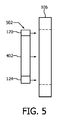
図4、図5及び図6は、例示のX線放射線源120及び散乱防止グリッド124に関連して検出器リング106を概略的に示す。図4は、検査領域108に向かってリング106のアパーチャを見た図を示す。図5及び図6は、検査領域108の外(図5)に及び中(図6)にX線放射線源120及び散乱防止グリッド124をそれぞれ有する検出器リング106の側面図を示す。
4, 5 and 6 schematically show the
この例において、キャリッジ又は支持体402は、X線管120及び散乱防止グリッド124の両方を支持する。支持体402及びゆえにX線管120及び散乱防止グリッド124は、少なくとも検査領域108の外側の位置502(図5)と検査領域108の内側の位置602(図6)との間で並進するように、スキャナ102に可動的に載置される。支持体402及びゆえにX線管120及び散乱防止グリッド124は更に、検査領域108のまわりを回転するように構成される。
In this example, the carriage or
支持体402は、スライド部、ボール、軸受、その他を通じてPET/CTスキャナ102において結合されることができ、モータ及びベルト、チェーン、リードスクリュー、ギア等により、位置502と位置60との間で移動されることができる。コントローラは、スキャナ102がPETモードであるか又はCTモードであるかに基づいてモータを駆動する。PETモードにおいて、支持体402は、PETイメージングのための位置502に配置され、CTモードでは、支持体402は、CTイメージングのための位置602に配置される。
The
図4−図6は、PET及びCTイメージングのそれぞれのために検査領域108の外へ及び中へ移動するように構成される同一の支持体(同一の支持体402)に取り付けられるX線管120及び散乱防止グリッド124を示すために提供されている。層106、支持体402、X線管120及び散乱防止グリッド124の相対寸法及び/又は位置は、制限的でないことが理解されるべきである。
FIG. 4-FIG. 6 shows an
図7は、X線放射線源120が、リング106の全体にわたって、モジュール1181、1182、1183、1184、...の間のギャップ7041、7042、7043、7044、...に位置する固体X線生成器7021、7022、7023、7024、...を有する変更例を概略的に示す。X線生成器7021、7022、7023、7024、...は、リングの全外周についてCTデータを得るために順にパルス化される。
In FIG. 7, the
1つの例において、散乱防止グリッド124は、図4、図5及び図6に関連して記述されたように支持体402に取り付けられ、生成器7021、7022、7023、7024、...の活性化と協働して、移動されることができる。変形例において、散乱防止グリッド124は、完全な円であり、502と602の間で並進するが、図4−図6のように検査領域のまわりを回転しない。
In one example, the
図8は、一実施形態による例示の方法を示す。以下の処理の順序は、説明の目的であり、制限的でないことが理解されることができる。従って、他の順序もまた企図される。更に、処理の1又は複数は省かれることができ、及び/又は1又は複数の他の処理が含められることができる。 FIG. 8 shows an exemplary method according to one embodiment. It can be understood that the following sequence of processing is for illustration purposes and is not restrictive. Therefore, other orders are also contemplated. Further, one or more of the processes can be omitted and / or one or more other processes can be included.
ステップ802において、ガンマ放射線は、イメージングシステムの2重層イメージング検出器の第1の層及び第2の層によって検出され、第1及び第2の層は、検出されたガンマ放射線を表す第1及び第2の信号を生成する。
In
ステップ804において、第1及び第2の信号が、PET画像データを生成するように処理される。 In step 804, the first and second signals are processed to generate PET image data.
ステップ806において、X線放射線は、イメージングシステムの2重層イメージング検出器の同じ第1の層によって検出され、第1の層は、検出されたX線放射線を示す第3の信号を生成する。 In step 806, the X-ray radiation is detected by the same first layer of the double layer imaging detector of the imaging system, which produces a third signal indicating the detected X-ray radiation.
ステップ808において、第3の信号が、CT画像データを生成するように処理される。
In
ステップ810において、PET及びCT画像データは、組み合わせられ、表示される。
In
本発明は、さまざまな実施形態を参照してここに記述された。変形例及び変更例が、本願明細書の記述を読むことにより当業者に思いつくであろう。本発明は、このような変更例及び変形例が添付の請求項又はそれと等価なものの範囲内にある限り、すべてのこのような変更例及び変形例を含むものとして解釈されることが意図される。
以下、本発明の各種形態を付記する。
(付記1)
少なくとも1つの検出器リングを有する放射線感受性検出器アレイを有し、
前記検出器リングは、
ガンマ放射線及びX線放射線を検出し、検出されたガンマ放射線及びX線放射線を表す信号を生成する第1の層と、
ガンマ放射線のみを検出し、検出されたガンマ放射線を表す信号を生成する第2の層と、
を有し、
前記第1の層及び前記第2の層が、前記少なくとも1つの検出器リングの同心のリングである、イメージングシステム。
(付記2)
単一のガントリを更に有し、
同心の前記第1及び前記第2の層を有する前記少なくとも1つの検出器リングが、前記単一のガントリに配置されている、付記1に記載のイメージングシステム。
(付記3)
前記第1の層によって検出されたガンマ放射線、前記第1の層によって検出されたX線放射線、及び前記第2の層によって検出されたガンマ放射線を表す信号を処理する信号プリプロセッサを更に有する、付記1又は2に記載のイメージングシステム。
(付記4)
前記第1の層によって検出されたガンマ放射線、前記第1の層によって検出されたX線放射線及び前記第2の層によって検出されたガンマ放射線を表す処理された信号を、再構成し、ポジトロンエミッショントモグラフィ(PET)及びコンピュータトモグラフィ(CT)画像データを生成する再構成器を更に有する、付記3に記載のイメージングシステム。
(付記5)
信号プリプロセッサが、
PETエネルギー閾値の予め決められた組に基づいて、前記第1の層によって検出されたガンマ放射線を、PETエネルギービンの予め決められた組にビニングし、
CTエネルギー閾値の予め決められた組に基づいて、前記第1の層によって検出されたX線放射線を、CTエネルギービンの予め決められた組にビニングする、付記1乃至4のいずれか1項に記載のイメージングシステム。
(付記6)
前記信号プリプロセッサが、前記PETエネルギービンの組の511keV光子の位置を、前記第2の層の対応するピクセルロケーションに外挿する、付記5に記載のイメージングシステム。
(付記7)
前記信号プリプロセッサは、前記PETエネルギービンの組からのエネルギー情報及びPET及びCTのタイミング情報を利用して、部分的に前記第1の層において及び部分的に前記第2の層において吸収されたコンプトン光子を合計して、前記第2の層の対応するピクセルロケーションに関する511keV光子を与える、付記5又は6に記載のイメージングシステム。
(付記8)
前記信号プリプロセッサは、前記第2の層によって検出されたガンマ放射線に基づいて、ラインオブレスポンスに沿った同時ガンマ対を識別する、付記5乃至7のいずれか1項に記載のイメージングシステム。
(付記9)
前記信号プリプロセッサは、前記ラインオブレスポンスに沿った同時ガンマ対のロケーションを算出する、付記8に記載のイメージングシステム。
(付記10)
前記再構成器は、CTエネルギービンの組の予め決められた1つからの、前記第1の層によって検出されたX線放射線を再構成する、付記1乃至9のいずれか1項に記載のイメージングシステム。
(付記11)
前記第1の層が、直接変換材料を有し、前記直接変換材料は、テルル化カドミウム亜鉛、複数のシリコンストリップ又は固体ガーネットを含む、付記1乃至10のいずれか1項に記載のイメージングシステム。
(付記12)
前記第1の層が、直接変換材料を有し、前記直接変換材料が、それに埋め込まれるシンチレーション材料の量子ドットを有するカプセル化材料を有する、付記1乃至10のいずれか1項に記載のイメージングシステム。
(付記13)
前記第1の層が、フォトセンサに光学的に結合されるシンチレータを有する、付記1乃至10のいずれか1項に記載のイメージングシステム。
(付記14)
前記X線放射線源は、PETデータを取得するために検査領域の外に移動され、CTデータを取得するために前記検査領域の中に移動される、付記1乃至13のいずれか1項に記載のイメージングシステム。
(付記15)
PETスキャンの場合は検査領域から外に移動され、CTスキャンの場合は前記検査領域の中に移動される散乱防止グリッドを更に有する、付記1乃至14のいずれか1項に記載のイメージングシステム。
(付記16)
PETモードでのイメージングに応答して、2重層PET/CT検出器の第1の層によりガンマ放射線を検出するステップと、
PETモードでのイメージングに応答して、2重層PET/CT検出器の第2の層によりガンマ放射線を検出するステップと、
前記第1及び前記第2の層によって検出されたガンマ放射線によりPET画像データを生成するステップと、
CTモードでのイメージングに応答して、2重層PET/CT検出器の前記第1の層によりX線放射線を検出するステップと、
前記第1の層により検出されたX線放射線によりCT画像データを生成するステップと、
PET画像データ及びCT画像データを視覚的に表示するステップと、
を含む方法。
(付記17)
前記第1の層によって検出されたガンマ放射線を、511keVを含むエネルギービンにエネルギービニングするステップと、
エネルギービニングされたガンマ放射線からの511keVの光子の位置を、前記第2の層のピクセルロケーションに外挿するステップと、
を更に含む、付記16に記載の方法。
(付記18)
前記第1の層によって検出されたガンマ放射線を、120keV乃至480keVのウィンドウを有するエネルギービンにエネルギービニングするステップと、
エネルギービニングされたガンマ放射線に基づいて、前記第1の層に吸収されるスプリットしたコンプトン光子を識別するステップと、
前記第1及び前記第2の層のタイミング情報に基づいて、前記第1の層に吸収され識別されたスプリットしたコンプトン光子を、前記第2の層に吸収されたスプリットしたコンプトン光子の残りの部分と合計し、前記第2の層のピクセルの511keV光子とするステップと、
を更に含む、付記16又は17のいずれか1項に記載の方法。
(付記19)
10keVから120keVまでのエネルギーレンジにわたるエネルギービンの予め決められた組に、前記第1の層によって検出されたX線放射線をエネルギービニングするステップと、
前記エネルギービンの組の中の少なくとも1つのビンにエネルギービニングされたX線放射線を選択的に再構成するステップと、
を更に含む、付記16乃至18のいずれか1項に記載の方法。
(付記20)
前記PET画像データに前記CT画像データを重ね合せるステップを更に含む、付記16乃至19のいずれか1項に記載の方法。
(付記21)
複数の検出器モジュールを有する少なくとも1つのリングを有し、各検出器モジュールが、複数の検出器を有し、
各検出器が、
ガンマ放射線及びX線放射線を検出し、検出されたガンマ放射線及びX線放射線を示す信号を生成する複数の第1のピクセルを有する第1の層と、
ガンマ放射線のみを検出し、検出されたガンマ放射線を示す信号を生成する複数の第2のピクセルを有する第2の層と、
を有し、前記第1及び前記第2の層が、一方の層の上に他方の層をのせて垂直方向に、入射ガンマ放射線及びX線放射線の方向に、スタックされる、イメージング検出器アレイ。
The present invention has been described herein with reference to various embodiments. Modifications and modifications will come to those skilled in the art by reading the description herein. The present invention is intended to be construed as including all such modifications and variations as long as such modifications and modifications are within the scope of the appended claims or equivalents. ..
Hereinafter, various forms of the present invention will be added.
(Appendix 1)
Having a radiosensitivity detector array with at least one detector ring,
The detector ring
A first layer that detects gamma and x-ray radiation and produces a signal representing the detected gamma and x-ray radiation.
A second layer that detects only gamma radiation and produces a signal representing the detected gamma radiation,
Have,
An imaging system in which the first layer and the second layer are concentric rings of the at least one detector ring.
(Appendix 2)
Has a single gantry and
The imaging system according to Appendix 1, wherein at least one detector ring having the first and second layers concentric is arranged in the single gantry.
(Appendix 3)
The appendix further comprises a signal preprocessor that processes signals representing gamma radiation detected by the first layer, X-ray radiation detected by the first layer, and gamma radiation detected by the second layer. The imaging system according to 1 or 2.
(Appendix 4)
The processed signals representing the gamma radiation detected by the first layer, the X-ray radiation detected by the first layer and the gamma radiation detected by the second layer are reconstructed and positron emissions. The imaging system according to Appendix 3, further comprising a reconstructor that produces tomography (PET) and computed tomography (CT) image data.
(Appendix 5)
The signal preprocessor,
Based on a predetermined set of PET energy thresholds, the gamma radiation detected by the first layer is binned into a predetermined set of PET energy bins.
In any one of Appendix 1 to 4, binning the X-ray radiation detected by the first layer into a predetermined set of CT energy bins based on a predetermined set of CT energy thresholds. The imaging system described.
(Appendix 6)
The imaging system according to Appendix 5, wherein the signal preprocessor extrapolates the position of the 511 keV photons in the PET energy bin set to the corresponding pixel location of the second layer.
(Appendix 7)
The signal preprocessor utilizes energy information from the PET energy bin set and PET and CT timing information to partially absorb in the first layer and partially in the second layer. The imaging system according to Appendix 5 or 6, wherein the photons are summed to give 511 keV photons for the corresponding pixel location of the second layer.
(Appendix 8)
The imaging system according to any one of Supplementary note 5 to 7, wherein the signal preprocessor identifies simultaneous gamma pairs along a line of response based on the gamma radiation detected by the second layer.
(Appendix 9)
The imaging system according to Appendix 8, wherein the signal preprocessor calculates the location of simultaneous gamma pairs along the line of response.
(Appendix 10)
The reconstructor according to any one of Supplementary notes 1 to 9, wherein the reconstructor reconstructs the X-ray radiation detected by the first layer from a predetermined one of a set of CT energy bins. Imaging system.
(Appendix 11)
The imaging system according to any one of Appendix 1 to 10, wherein the first layer comprises a direct conversion material, wherein the direct conversion material comprises cadmium telluride zinc, a plurality of silicon strips or a solid garnet.
(Appendix 12)
The imaging system according to any one of Supplementary note 1 to 10, wherein the first layer has a direct conversion material, and the direct conversion material has an encapsulation material having quantum dots of a scintillation material embedded therein. ..
(Appendix 13)
The imaging system according to any one of Supplementary note 1 to 10, wherein the first layer has a scintillator optically coupled to a photosensor.
(Appendix 14)
The item according to any one of Appendix 1 to 13, wherein the X-ray radiation source is moved out of the inspection area to acquire PET data and is moved into the inspection area to acquire CT data. Imaging system.
(Appendix 15)
The imaging system according to any one of Appendix 1 to 14, further comprising an anti-scattering grid that is moved out of the inspection area in the case of PET scans and into the inspection area in the case of CT scans.
(Appendix 16)
In response to imaging in PET mode, the step of detecting gamma radiation by the first layer of the double layer PET / CT detector,
In response to imaging in PET mode, the step of detecting gamma radiation by the second layer of the double layer PET / CT detector,
A step of generating PET image data from the gamma radiation detected by the first and second layers, and
A step of detecting X-ray radiation by the first layer of a double layer PET / CT detector in response to imaging in CT mode.
A step of generating CT image data from the X-ray radiation detected by the first layer, and
Steps to visually display PET image data and CT image data,
How to include.
(Appendix 17)
A step of energy binning the gamma radiation detected by the first layer into an energy bin containing 511 keV,
The step of extrapolating the position of the 511 keV photon from the energy binned gamma radiation to the pixel location of the second layer,
The method according to Appendix 16, further comprising.
(Appendix 18)
A step of energy binning the gamma radiation detected by the first layer into an energy bin having a window of 120 keV to 480 keV.
A step of identifying split Compton photons absorbed by the first layer based on energy binned gamma radiation.
Based on the timing information of the first and second layers, the split Compton photons absorbed and identified by the first layer are the remaining portion of the split Compton photons absorbed by the second layer. And the step of adding up to 511 keV photons of the pixels of the second layer.
The method according to any one of Appendix 16 or 17, further comprising.
(Appendix 19)
A step of energy binning the X-ray radiation detected by the first layer into a predetermined set of energy bins over an energy range from 10 keV to 120 keV.
A step of selectively reconstructing energy-binned X-ray radiation into at least one of the energy bin sets.
The method according to any one of Appendix 16 to 18, further comprising.
(Appendix 20)
The method according to any one of Appendix 16 to 19, further comprising a step of superimposing the CT image data on the PET image data.
(Appendix 21)
Have at least one ring with multiple detector modules, each detector module having multiple detectors
Each detector
A first layer having a plurality of first pixels that detect gamma and x-ray radiation and generate a signal indicating the detected gamma and x-ray radiation, and
A second layer having multiple second pixels that detect only gamma radiation and generate a signal indicating the detected gamma radiation,
The first and second layers are stacked vertically, in the direction of incident gamma radiation and X-ray radiation, with the other layer on top of one layer. ..
Claims (15)
前記検出器リングは、
ガンマ放射線及びX線放射線を検出し、検出されたガンマ放射線及びX線放射線を表す信号を生成する第1の層と、
ガンマ放射線のみを検出し、検出されたガンマ放射線を表す信号を生成する第2の層と、
を有し、
前記第1の層及び前記第2の層が、前記少なくとも1つの検出器リングの同心のリングである、
放射線感受性検出器アレイと、
前記第1の層によって検出されたガンマ放射線、前記第1の層によって検出されたX線放射線、及び前記第2の層によって検出されたガンマ放射線を表す信号を処理する信号プリプロセッサと、
を有し、
前記信号プリプロセッサは、前記第1の層から出力される信号を、予め決められた複数のエネルギー閾値に基づいて複数のエネルギービンにビニングし、
前記信号プリプロセッサが、
前記第1の層によって検出されたガンマ放射線を、前記複数のエネルギー閾値のうちPETエネルギー閾値の予め決められた組に基づいてPETエネルギービンの予め決められた組にビニングし、
前記第1の層によって検出されたX線放射線を、前記複数のエネルギー閾値のうちCTエネルギー閾値の予め決められた組に基づいてCTエネルギービンの予め決められた組にビニングする、
イメージングシステム。 A radiation sensitive detector array with at least one detector ring.
The detector ring
A first layer that detects gamma and x-ray radiation and produces a signal representing the detected gamma and x-ray radiation.
A second layer that detects only gamma radiation and produces a signal representing the detected gamma radiation,
Have,
The first layer and the second layer are concentric rings of the at least one detector ring.
Radiation sensitivity detector array and
A signal preprocessor that processes signals representing gamma radiation detected by the first layer, X-ray radiation detected by the first layer, and gamma radiation detected by the second layer.
Have,
The signal preprocessor binners the signal output from the first layer into a plurality of energy bins based on a plurality of predetermined energy threshold values.
The signal preprocessor
Gamma radiation detected by said first layer, and binning the predetermined set of P ET energy bins based on a predetermined set of PET energy threshold of the plurality of energy thresholds,
The X-ray radiation detected by said first layer, binning to a predetermined set of C T energy bins based on a predetermined set of CT energy threshold of the plurality of energy thresholds,
Imaging system.
同心の前記第1及び前記第2の層を有する前記少なくとも1つの検出器リングが、前記単一のガントリに配置されている、請求項1に記載のイメージングシステム。 Has a single gantry and
The imaging system according to claim 1, wherein at least one detector ring having the first and second layers concentric is arranged in the single gantry.
PETモードでのイメージングに応答して、2重層PET/CT検出器の第2の層によりガンマ放射線を検出するステップと、
前記第1及び前記第2の層によって検出されたガンマ放射線によりPET画像データを生成するステップと、
CTモードでのイメージングに応答して、2重層PET/CT検出器の前記第1の層によりX線放射線を検出するステップと、
前記第1の層により検出されたX線放射線によりCT画像データを生成するステップと、
PET画像データ及びCT画像データを視覚的に表示するステップと、
を有し、
前記第1の層から出力される信号は、予め決められた複数のエネルギー閾値に基づいて複数のエネルギービンにビニングされ、
前記第1の層により検出された前記ガンマ放射線は、前記複数のエネルギー閾値のうちPETエネルギー閾値の予め決められた組に基づいて、PETエネルギービンの予め決められた組にビニングされ、前記第1の層により検出されたX線放射線は、前記複数のエネルギー閾値のうちCTエネルギー閾値の予め決められた組に基づいて、CTエネルギービンの予め決められた組にビニングされる、
方法。 In response to imaging in PET mode, the step of detecting gamma radiation by the first layer of the double layer PET / CT detector,
In response to imaging in PET mode, the step of detecting gamma radiation by the second layer of the double layer PET / CT detector,
A step of generating PET image data from the gamma radiation detected by the first and second layers, and
A step of detecting X-ray radiation by the first layer of a double layer PET / CT detector in response to imaging in CT mode.
A step of generating CT image data from the X-ray radiation detected by the first layer, and
Steps to visually display PET image data and CT image data,
Have,
The signal output from the first layer is binned into a plurality of energy bins based on a plurality of predetermined energy threshold values.
The gamma radiation detected by the first layer is binned into a predetermined set of PET energy bins based on a predetermined set of PET energy thresholds among the plurality of energy thresholds, and the first The X-ray radiation detected by the layer is binned into a predetermined set of CT energy bins based on a predetermined set of CT energy thresholds among the plurality of energy thresholds.
Method.
エネルギービニングされたガンマ放射線からの511keVの光子の位置を、前記第2の層のピクセルロケーションに外挿するステップと、
を更に含む、請求項12に記載の方法。 A step of energy binning the gamma radiation detected by the first layer into an energy bin containing 511 keV,
The step of extrapolating the position of the 511 keV photon from the energy binned gamma radiation to the pixel location of the second layer,
12. The method of claim 12.
エネルギービニングされたガンマ放射線に基づいて、前記第1の層に吸収されるスプリットしたコンプトン光子を識別するステップと、
前記第1及び前記第2の層のタイミング情報に基づいて、前記第1の層に吸収され識別されたスプリットしたコンプトン光子を、前記第2の層に吸収されたスプリットしたコンプトン光子の残りの部分と合計し、前記第2の層のピクセルの511keV光子とするステップと、
を更に含む、請求項12又は13のいずれか1項に記載の方法。 A step of energy binning the gamma radiation detected by the first layer into an energy bin having a window of 120 keV to 480 keV.
A step of identifying split Compton photons absorbed by the first layer based on energy binned gamma radiation.
Based on the timing information of the first and second layers, the split Compton photons absorbed and identified by the first layer are the remaining portion of the split Compton photons absorbed by the second layer. And the step of adding up to 511 keV photons of the pixels of the second layer.
The method according to any one of claims 12 or 13, further comprising.
前記エネルギービンの組の中の少なくとも1つのビンにエネルギービニングされたX線放射線を選択的に再構成するステップと、
を更に含む、請求項12乃至14のいずれか1項に記載の方法。 A step of energy binning the X-ray radiation detected by the first layer into a predetermined set of energy bins over an energy range from 10 keV to 120 keV.
A step of selectively reconstructing energy-binned X-ray radiation into at least one of the energy bin sets.
The method according to any one of claims 12 to 14, further comprising.
Applications Claiming Priority (3)
| Application Number | Priority Date | Filing Date | Title |
|---|---|---|---|
| US201562202414P | 2015-08-07 | 2015-08-07 | |
| US62/202,414 | 2015-08-07 | ||
| PCT/IB2016/054493 WO2017025842A1 (en) | 2015-08-07 | 2016-07-28 | Hybrid pet / ct imaging detector |
Publications (3)
| Publication Number | Publication Date |
|---|---|
| JP2018527981A JP2018527981A (en) | 2018-09-27 |
| JP2018527981A5 JP2018527981A5 (en) | 2019-08-29 |
| JP6854805B2 true JP6854805B2 (en) | 2021-04-07 |
Family
ID=56738138
Family Applications (1)
| Application Number | Title | Priority Date | Filing Date |
|---|---|---|---|
| JP2018506302A Active JP6854805B2 (en) | 2015-08-07 | 2016-07-28 | Hybrid PET / CT imaging detector |
Country Status (5)
| Country | Link |
|---|---|
| US (1) | US10247832B2 (en) |
| EP (1) | EP3332269B1 (en) |
| JP (1) | JP6854805B2 (en) |
| CN (1) | CN107923982B (en) |
| WO (1) | WO2017025842A1 (en) |
Families Citing this family (18)
| Publication number | Priority date | Publication date | Assignee | Title |
|---|---|---|---|---|
| ES2629092B1 (en) * | 2015-11-04 | 2018-07-04 | Consejo Superior De Investigaciones Científicas (Csic) | GAMMA RAY COMPTON CAMERA SYSTEM WITH FLIGHT TIME MEASUREMENT |
| EP3559704B1 (en) * | 2016-12-21 | 2020-09-30 | Koninklijke Philips N.V. | Protection of a gamma radiation detector |
| US10413256B2 (en) * | 2017-09-13 | 2019-09-17 | LiteRay Medical, LLC | Systems and methods for ultra low dose CT fluoroscopy |
| DE102017221924B3 (en) * | 2017-12-05 | 2019-05-02 | Siemens Healthcare Gmbh | Method for merging an analysis data set with an image data record, positioning device and computer program |
| JP6986487B2 (en) * | 2018-05-17 | 2021-12-22 | 浜松ホトニクス株式会社 | Method of acquiring gamma ray generation position of scattering simultaneous counting in PET apparatus and PET apparatus |
| US11500054B2 (en) | 2018-05-17 | 2022-11-15 | Navico Holding As | Marine chart and sonar image presentation systems and methods |
| FR3081231B1 (en) * | 2018-05-18 | 2020-06-12 | Damavan Imaging | GAMMA RADIATION DETECTION IMAGING SYSTEM AND METHOD |
| EP3818395B1 (en) * | 2018-08-07 | 2023-02-08 | Siemens Medical Solutions USA, Inc. | Compton camera with segmented detection modules |
| CN109223014A (en) * | 2018-08-31 | 2019-01-18 | 上海联影医疗科技有限公司 | Obtain method, detector device, medical supply and the storage medium of medical image |
| CN111068186B (en) * | 2018-10-22 | 2021-03-02 | 清华大学 | CT imaging and image-guided radiotherapy device |
| CN111375144B (en) * | 2018-12-29 | 2021-03-05 | 清华大学 | Tomographic and image-guided radiation therapy apparatus |
| US11179579B2 (en) | 2018-12-29 | 2021-11-23 | Tsinghua University | Tomographic imaging and image-guided radiation therapy apparatus |
| WO2020187808A1 (en) * | 2019-03-20 | 2020-09-24 | Koninklijke Philips N.V. | Quantum dot porous silicon membrane-based radiation detector |
| WO2020198935A1 (en) * | 2019-03-29 | 2020-10-08 | Shenzhen Xpectvision Technology Co., Ltd. | A method of imaging |
| CN113133772A (en) * | 2020-01-20 | 2021-07-20 | 上海交通大学 | PET-CT system and scanning method |
| CN111694046B (en) * | 2020-07-24 | 2022-06-07 | 中国工程物理研究院核物理与化学研究所 | Single-energy gamma device |
| US11947007B2 (en) | 2021-02-19 | 2024-04-02 | Navico, Inc. | Sonar beam zone presentation |
| US11921199B2 (en) | 2021-02-19 | 2024-03-05 | Navico, Inc. | Sonar beam footprint presentation |
Family Cites Families (22)
| Publication number | Priority date | Publication date | Assignee | Title |
|---|---|---|---|---|
| CA2252993C (en) | 1998-11-06 | 2011-04-19 | Universite De Sherbrooke | Detector assembly for multi-modality scanners |
| US7297958B2 (en) | 2001-12-03 | 2007-11-20 | Hitachi, Ltd. | Radiological imaging apparatus |
| JP3851575B2 (en) * | 2002-03-05 | 2006-11-29 | 株式会社日立製作所 | PET inspection equipment |
| JP4093013B2 (en) * | 2002-10-23 | 2008-05-28 | 株式会社日立製作所 | Radiation inspection equipment |
| GB0311881D0 (en) | 2003-05-22 | 2003-06-25 | Univ Aberdeen | A detector module for detecting ionizing radiation |
| DE102004049677B3 (en) * | 2004-10-12 | 2006-06-14 | Siemens Ag | Detector assembly for use in a combined transmission / emission tomography device |
| US20070085010A1 (en) * | 2005-06-14 | 2007-04-19 | The Regents Of The University Of California | Scintillator with a matrix material body carrying nano-material scintillator media |
| US7800070B2 (en) * | 2006-04-10 | 2010-09-21 | Quantum Molecular Technologies, Inc. | Quantum photodetectors, imaging apparatus and systems, and related methods |
| US7545902B2 (en) * | 2006-09-18 | 2009-06-09 | General Electric Company | Received x-ray handling methods and apparatus |
| US8299437B2 (en) * | 2007-05-15 | 2012-10-30 | National Institute Of Radiological Sciences | Gamma ray detector and gamma ray reconstruction method |
| US8059277B2 (en) * | 2007-08-27 | 2011-11-15 | Axsun Technologies, Inc. | Mode hopping swept frequency laser for FD OCT and method of operation |
| CN101401725B (en) * | 2007-09-27 | 2013-08-21 | 西门子公司 | Patient treatment using a hybrid imaging system |
| CN201365927Y (en) * | 2009-01-21 | 2009-12-23 | 北京亿仁赛博医疗设备有限公司 | PET/CT image fusion combining diagnosis equipment |
| JP5426282B2 (en) * | 2009-09-03 | 2014-02-26 | 株式会社東芝 | Diagnostic imaging equipment |
| EP2640270B1 (en) | 2010-11-18 | 2018-05-16 | Koninklijke Philips N.V. | Pet-ct system with single detector |
| US20120265050A1 (en) * | 2011-04-04 | 2012-10-18 | Ge Wang | Omni-Tomographic Imaging for Interior Reconstruction using Simultaneous Data Acquisition from Multiple Imaging Modalities |
| US20150003591A1 (en) * | 2012-01-24 | 2015-01-01 | Koninklijke Philips N.V. | Nuclear imaging system |
| WO2013144812A2 (en) * | 2012-03-27 | 2013-10-03 | Koninklijke Philips N.V. | Conventional imaging with an imaging system having photon counting detectors |
| CN103961124A (en) * | 2013-01-31 | 2014-08-06 | 北京大基康明医疗设备有限公司 | Combined diagnosis system integrating PET-CT functions |
| US9505977B2 (en) * | 2014-07-30 | 2016-11-29 | The United States of America Department of Energy | Gadolinium-loaded gel scintillators for neutron and antineutrino detection |
| EP3197981A1 (en) | 2014-09-23 | 2017-08-02 | Philips Lighting Holding B.V. | Encapsulated materials in porous particles |
| CN107850676B (en) | 2015-08-07 | 2022-01-14 | 皇家飞利浦有限公司 | Imaging detector based on quantum dots |
-
2016
- 2016-07-28 EP EP16753704.2A patent/EP3332269B1/en active Active
- 2016-07-28 WO PCT/IB2016/054493 patent/WO2017025842A1/en active Application Filing
- 2016-07-28 US US15/748,330 patent/US10247832B2/en active Active
- 2016-07-28 JP JP2018506302A patent/JP6854805B2/en active Active
- 2016-07-28 CN CN201680046429.1A patent/CN107923982B/en active Active
Also Published As
| Publication number | Publication date |
|---|---|
| WO2017025842A1 (en) | 2017-02-16 |
| CN107923982A (en) | 2018-04-17 |
| CN107923982B (en) | 2022-01-04 |
| JP2018527981A (en) | 2018-09-27 |
| EP3332269B1 (en) | 2020-09-09 |
| EP3332269A1 (en) | 2018-06-13 |
| US10247832B2 (en) | 2019-04-02 |
| US20180217273A1 (en) | 2018-08-02 |
Similar Documents
| Publication | Publication Date | Title |
|---|---|---|
| JP6854805B2 (en) | Hybrid PET / CT imaging detector | |
| CN108139491B (en) | Radiation detector for combined detection of low-energy and high-energy radiation quanta | |
| CA2252993C (en) | Detector assembly for multi-modality scanners | |
| US6399951B1 (en) | Simultaneous CT and SPECT tomography using CZT detectors | |
| EP2347285B1 (en) | Device for detecting highly energetic photons | |
| EP2640270B1 (en) | Pet-ct system with single detector | |
| KR100991640B1 (en) | Nuclear medical diagnostic device, form tomography diagnostic device, data arithmetic processing method for nuclear medicine, and form tomogram image processing method | |
| JP6499172B2 (en) | PET system with spacing in crystal or detector unit | |
| US8299437B2 (en) | Gamma ray detector and gamma ray reconstruction method | |
| US20100012845A1 (en) | Energy-resolving detection system and imaging system | |
| EP3320372B1 (en) | Device and method for simultaneous x-ray and gamma photon imaging with a stacked detector | |
| Patton et al. | Coincidence imaging with a dual-head scintillation camera | |
| EP2847617B1 (en) | Spect/pet imaging system | |
| CN113287056B (en) | Medical imaging system based on collimator and detector | |
| US6303935B1 (en) | Combination PET/SPECT nuclear imaging system | |
| JP2009175140A (en) | Nuclear medicine diagnostic apparatus, form tomography diagnostic apparatus, nuclear medicine data arithmetic processing method, and form tomogram arithmetic processing method | |
| US20230375727A1 (en) | Combined imaging detector and imaging system | |
| JP2009281816A (en) | Tomographic apparatus | |
| JP2015152356A (en) | Dark countless radiation detection energy discrimination imaging system | |
| KR102449932B1 (en) | Sensitivity enhancing method and system for radiation using compton effect |
Legal Events
| Date | Code | Title | Description |
|---|---|---|---|
| A521 | Request for written amendment filed |
Free format text: JAPANESE INTERMEDIATE CODE: A523 Effective date: 20190717 |
|
| A621 | Written request for application examination |
Free format text: JAPANESE INTERMEDIATE CODE: A621 Effective date: 20190717 |
|
| A977 | Report on retrieval |
Free format text: JAPANESE INTERMEDIATE CODE: A971007 Effective date: 20200630 |
|
| A131 | Notification of reasons for refusal |
Free format text: JAPANESE INTERMEDIATE CODE: A131 Effective date: 20200709 |
|
| A601 | Written request for extension of time |
Free format text: JAPANESE INTERMEDIATE CODE: A601 Effective date: 20201008 |
|
| A521 | Request for written amendment filed |
Free format text: JAPANESE INTERMEDIATE CODE: A523 Effective date: 20210112 |
|
| TRDD | Decision of grant or rejection written | ||
| A01 | Written decision to grant a patent or to grant a registration (utility model) |
Free format text: JAPANESE INTERMEDIATE CODE: A01 Effective date: 20210216 |
|
| A61 | First payment of annual fees (during grant procedure) |
Free format text: JAPANESE INTERMEDIATE CODE: A61 Effective date: 20210316 |
|
| R150 | Certificate of patent or registration of utility model |
Ref document number: 6854805 Country of ref document: JP Free format text: JAPANESE INTERMEDIATE CODE: R150 |
|
| R250 | Receipt of annual fees |
Free format text: JAPANESE INTERMEDIATE CODE: R250 |