EP3332269B1 - Hybrid pet / ct imaging detector - Google Patents
Hybrid pet / ct imaging detector Download PDFInfo
- Publication number
- EP3332269B1 EP3332269B1 EP16753704.2A EP16753704A EP3332269B1 EP 3332269 B1 EP3332269 B1 EP 3332269B1 EP 16753704 A EP16753704 A EP 16753704A EP 3332269 B1 EP3332269 B1 EP 3332269B1
- Authority
- EP
- European Patent Office
- Prior art keywords
- layer
- pet
- energy
- gamma radiation
- radiation detected
- Prior art date
- Legal status (The legal status is an assumption and is not a legal conclusion. Google has not performed a legal analysis and makes no representation as to the accuracy of the status listed.)
- Active
Links
- 238000003384 imaging method Methods 0.000 title claims description 37
- 239000010410 layer Substances 0.000 claims description 101
- 238000002600 positron emission tomography Methods 0.000 claims description 81
- 230000005855 radiation Effects 0.000 claims description 73
- 238000002591 computed tomography Methods 0.000 claims description 69
- 239000000463 material Substances 0.000 claims description 32
- 238000006243 chemical reaction Methods 0.000 claims description 19
- 238000000034 method Methods 0.000 claims description 15
- 230000004044 response Effects 0.000 claims description 10
- 239000002096 quantum dot Substances 0.000 claims description 9
- 239000002355 dual-layer Substances 0.000 claims description 8
- 230000008569 process Effects 0.000 claims description 4
- QWUZMTJBRUASOW-UHFFFAOYSA-N cadmium tellanylidenezinc Chemical compound [Zn].[Cd].[Te] QWUZMTJBRUASOW-UHFFFAOYSA-N 0.000 claims description 3
- XUIMIQQOPSSXEZ-UHFFFAOYSA-N Silicon Chemical compound [Si] XUIMIQQOPSSXEZ-UHFFFAOYSA-N 0.000 claims description 2
- 229910052710 silicon Inorganic materials 0.000 claims description 2
- 239000010703 silicon Substances 0.000 claims description 2
- 239000007787 solid Substances 0.000 claims description 2
- 239000002223 garnet Substances 0.000 claims 1
- 238000013170 computed tomography imaging Methods 0.000 description 6
- 238000007781 pre-processing Methods 0.000 description 6
- 238000012879 PET imaging Methods 0.000 description 3
- 239000002245 particle Substances 0.000 description 3
- MCVAAHQLXUXWLC-UHFFFAOYSA-N [O-2].[O-2].[S-2].[Gd+3].[Gd+3] Chemical compound [O-2].[O-2].[S-2].[Gd+3].[Gd+3] MCVAAHQLXUXWLC-UHFFFAOYSA-N 0.000 description 2
- 230000004075 alteration Effects 0.000 description 2
- ORCSMBGZHYTXOV-UHFFFAOYSA-N bismuth;germanium;dodecahydrate Chemical compound O.O.O.O.O.O.O.O.O.O.O.O.[Ge].[Ge].[Ge].[Bi].[Bi].[Bi].[Bi] ORCSMBGZHYTXOV-UHFFFAOYSA-N 0.000 description 2
- 230000005251 gamma ray Effects 0.000 description 2
- 238000004519 manufacturing process Methods 0.000 description 2
- 230000004048 modification Effects 0.000 description 2
- 238000012986 modification Methods 0.000 description 2
- 230000002285 radioactive effect Effects 0.000 description 2
- 239000002356 single layer Substances 0.000 description 2
- ANDNPYOOQLLLIU-UHFFFAOYSA-N [Y].[Lu] Chemical compound [Y].[Lu] ANDNPYOOQLLLIU-UHFFFAOYSA-N 0.000 description 1
- 239000011358 absorbing material Substances 0.000 description 1
- 238000010521 absorption reaction Methods 0.000 description 1
- 230000004913 activation Effects 0.000 description 1
- 210000003484 anatomy Anatomy 0.000 description 1
- 230000002238 attenuated effect Effects 0.000 description 1
- 230000008901 benefit Effects 0.000 description 1
- 239000003795 chemical substances by application Substances 0.000 description 1
- 238000010276 construction Methods 0.000 description 1
- 230000003247 decreasing effect Effects 0.000 description 1
- 230000001419 dependent effect Effects 0.000 description 1
- 230000000977 initiatory effect Effects 0.000 description 1
- 230000003993 interaction Effects 0.000 description 1
- 230000005258 radioactive decay Effects 0.000 description 1
- 230000003595 spectral effect Effects 0.000 description 1
- 238000001228 spectrum Methods 0.000 description 1
- 230000002123 temporal effect Effects 0.000 description 1
- WFKWXMTUELFFGS-UHFFFAOYSA-N tungsten Chemical compound [W] WFKWXMTUELFFGS-UHFFFAOYSA-N 0.000 description 1
- 229910052721 tungsten Inorganic materials 0.000 description 1
- 239000010937 tungsten Substances 0.000 description 1
- 230000002747 voluntary effect Effects 0.000 description 1
Images


Classifications
-
- A—HUMAN NECESSITIES
- A61—MEDICAL OR VETERINARY SCIENCE; HYGIENE
- A61B—DIAGNOSIS; SURGERY; IDENTIFICATION
- A61B6/00—Apparatus for radiation diagnosis, e.g. combined with radiation therapy equipment
- A61B6/42—Apparatus for radiation diagnosis, e.g. combined with radiation therapy equipment with arrangements for detecting radiation specially adapted for radiation diagnosis
- A61B6/4275—Apparatus for radiation diagnosis, e.g. combined with radiation therapy equipment with arrangements for detecting radiation specially adapted for radiation diagnosis using a detector unit almost surrounding the patient, e.g. more than 180°
-
- G—PHYSICS
- G01—MEASURING; TESTING
- G01T—MEASUREMENT OF NUCLEAR OR X-RADIATION
- G01T1/00—Measuring X-radiation, gamma radiation, corpuscular radiation, or cosmic radiation
- G01T1/16—Measuring radiation intensity
- G01T1/161—Applications in the field of nuclear medicine, e.g. in vivo counting
- G01T1/1615—Applications in the field of nuclear medicine, e.g. in vivo counting using both transmission and emission sources simultaneously
- G01T1/1617—Applications in the field of nuclear medicine, e.g. in vivo counting using both transmission and emission sources simultaneously with scintillation detectors
-
- A—HUMAN NECESSITIES
- A61—MEDICAL OR VETERINARY SCIENCE; HYGIENE
- A61B—DIAGNOSIS; SURGERY; IDENTIFICATION
- A61B6/00—Apparatus for radiation diagnosis, e.g. combined with radiation therapy equipment
- A61B6/02—Devices for diagnosis sequentially in different planes; Stereoscopic radiation diagnosis
- A61B6/03—Computerised tomographs
- A61B6/032—Transmission computed tomography [CT]
-
- A—HUMAN NECESSITIES
- A61—MEDICAL OR VETERINARY SCIENCE; HYGIENE
- A61B—DIAGNOSIS; SURGERY; IDENTIFICATION
- A61B6/00—Apparatus for radiation diagnosis, e.g. combined with radiation therapy equipment
- A61B6/02—Devices for diagnosis sequentially in different planes; Stereoscopic radiation diagnosis
- A61B6/03—Computerised tomographs
- A61B6/037—Emission tomography
-
- A—HUMAN NECESSITIES
- A61—MEDICAL OR VETERINARY SCIENCE; HYGIENE
- A61B—DIAGNOSIS; SURGERY; IDENTIFICATION
- A61B6/00—Apparatus for radiation diagnosis, e.g. combined with radiation therapy equipment
- A61B6/42—Apparatus for radiation diagnosis, e.g. combined with radiation therapy equipment with arrangements for detecting radiation specially adapted for radiation diagnosis
- A61B6/4208—Apparatus for radiation diagnosis, e.g. combined with radiation therapy equipment with arrangements for detecting radiation specially adapted for radiation diagnosis characterised by using a particular type of detector
- A61B6/4233—Apparatus for radiation diagnosis, e.g. combined with radiation therapy equipment with arrangements for detecting radiation specially adapted for radiation diagnosis characterised by using a particular type of detector using matrix detectors
-
- A—HUMAN NECESSITIES
- A61—MEDICAL OR VETERINARY SCIENCE; HYGIENE
- A61B—DIAGNOSIS; SURGERY; IDENTIFICATION
- A61B6/00—Apparatus for radiation diagnosis, e.g. combined with radiation therapy equipment
- A61B6/42—Apparatus for radiation diagnosis, e.g. combined with radiation therapy equipment with arrangements for detecting radiation specially adapted for radiation diagnosis
- A61B6/4208—Apparatus for radiation diagnosis, e.g. combined with radiation therapy equipment with arrangements for detecting radiation specially adapted for radiation diagnosis characterised by using a particular type of detector
- A61B6/4241—Apparatus for radiation diagnosis, e.g. combined with radiation therapy equipment with arrangements for detecting radiation specially adapted for radiation diagnosis characterised by using a particular type of detector using energy resolving detectors, e.g. photon counting
-
- A—HUMAN NECESSITIES
- A61—MEDICAL OR VETERINARY SCIENCE; HYGIENE
- A61B—DIAGNOSIS; SURGERY; IDENTIFICATION
- A61B6/00—Apparatus for radiation diagnosis, e.g. combined with radiation therapy equipment
- A61B6/42—Apparatus for radiation diagnosis, e.g. combined with radiation therapy equipment with arrangements for detecting radiation specially adapted for radiation diagnosis
- A61B6/4266—Apparatus for radiation diagnosis, e.g. combined with radiation therapy equipment with arrangements for detecting radiation specially adapted for radiation diagnosis characterised by using a plurality of detector units
-
- A—HUMAN NECESSITIES
- A61—MEDICAL OR VETERINARY SCIENCE; HYGIENE
- A61B—DIAGNOSIS; SURGERY; IDENTIFICATION
- A61B6/00—Apparatus for radiation diagnosis, e.g. combined with radiation therapy equipment
- A61B6/42—Apparatus for radiation diagnosis, e.g. combined with radiation therapy equipment with arrangements for detecting radiation specially adapted for radiation diagnosis
- A61B6/4291—Apparatus for radiation diagnosis, e.g. combined with radiation therapy equipment with arrangements for detecting radiation specially adapted for radiation diagnosis the detector being combined with a grid or grating
-
- A—HUMAN NECESSITIES
- A61—MEDICAL OR VETERINARY SCIENCE; HYGIENE
- A61B—DIAGNOSIS; SURGERY; IDENTIFICATION
- A61B6/00—Apparatus for radiation diagnosis, e.g. combined with radiation therapy equipment
- A61B6/44—Constructional features of apparatus for radiation diagnosis
- A61B6/4417—Constructional features of apparatus for radiation diagnosis related to combined acquisition of different diagnostic modalities
-
- A—HUMAN NECESSITIES
- A61—MEDICAL OR VETERINARY SCIENCE; HYGIENE
- A61B—DIAGNOSIS; SURGERY; IDENTIFICATION
- A61B6/00—Apparatus for radiation diagnosis, e.g. combined with radiation therapy equipment
- A61B6/48—Diagnostic techniques
- A61B6/482—Diagnostic techniques involving multiple energy imaging
-
- A—HUMAN NECESSITIES
- A61—MEDICAL OR VETERINARY SCIENCE; HYGIENE
- A61B—DIAGNOSIS; SURGERY; IDENTIFICATION
- A61B6/00—Apparatus for radiation diagnosis, e.g. combined with radiation therapy equipment
- A61B6/52—Devices using data or image processing specially adapted for radiation diagnosis
- A61B6/5205—Devices using data or image processing specially adapted for radiation diagnosis involving processing of raw data to produce diagnostic data
-
- A—HUMAN NECESSITIES
- A61—MEDICAL OR VETERINARY SCIENCE; HYGIENE
- A61B—DIAGNOSIS; SURGERY; IDENTIFICATION
- A61B6/00—Apparatus for radiation diagnosis, e.g. combined with radiation therapy equipment
- A61B6/52—Devices using data or image processing specially adapted for radiation diagnosis
- A61B6/5211—Devices using data or image processing specially adapted for radiation diagnosis involving processing of medical diagnostic data
- A61B6/5229—Devices using data or image processing specially adapted for radiation diagnosis involving processing of medical diagnostic data combining image data of a patient, e.g. combining a functional image with an anatomical image
- A61B6/5235—Devices using data or image processing specially adapted for radiation diagnosis involving processing of medical diagnostic data combining image data of a patient, e.g. combining a functional image with an anatomical image combining images from the same or different ionising radiation imaging techniques, e.g. PET and CT
-
- A—HUMAN NECESSITIES
- A61—MEDICAL OR VETERINARY SCIENCE; HYGIENE
- A61B—DIAGNOSIS; SURGERY; IDENTIFICATION
- A61B6/00—Apparatus for radiation diagnosis, e.g. combined with radiation therapy equipment
- A61B6/52—Devices using data or image processing specially adapted for radiation diagnosis
- A61B6/5258—Devices using data or image processing specially adapted for radiation diagnosis involving detection or reduction of artifacts or noise
- A61B6/5282—Devices using data or image processing specially adapted for radiation diagnosis involving detection or reduction of artifacts or noise due to scatter
-
- G—PHYSICS
- G01—MEASURING; TESTING
- G01T—MEASUREMENT OF NUCLEAR OR X-RADIATION
- G01T1/00—Measuring X-radiation, gamma radiation, corpuscular radiation, or cosmic radiation
- G01T1/16—Measuring radiation intensity
- G01T1/1603—Measuring radiation intensity with a combination of at least two different types of detector
-
- G—PHYSICS
- G01—MEASURING; TESTING
- G01T—MEASUREMENT OF NUCLEAR OR X-RADIATION
- G01T1/00—Measuring X-radiation, gamma radiation, corpuscular radiation, or cosmic radiation
- G01T1/16—Measuring radiation intensity
- G01T1/161—Applications in the field of nuclear medicine, e.g. in vivo counting
- G01T1/1615—Applications in the field of nuclear medicine, e.g. in vivo counting using both transmission and emission sources simultaneously
-
- G—PHYSICS
- G01—MEASURING; TESTING
- G01T—MEASUREMENT OF NUCLEAR OR X-RADIATION
- G01T1/00—Measuring X-radiation, gamma radiation, corpuscular radiation, or cosmic radiation
- G01T1/16—Measuring radiation intensity
- G01T1/161—Applications in the field of nuclear medicine, e.g. in vivo counting
- G01T1/164—Scintigraphy
-
- G—PHYSICS
- G01—MEASURING; TESTING
- G01T—MEASUREMENT OF NUCLEAR OR X-RADIATION
- G01T1/00—Measuring X-radiation, gamma radiation, corpuscular radiation, or cosmic radiation
- G01T1/16—Measuring radiation intensity
- G01T1/20—Measuring radiation intensity with scintillation detectors
- G01T1/2008—Measuring radiation intensity with scintillation detectors using a combination of different types of scintillation detectors, e.g. phoswich
-
- G—PHYSICS
- G01—MEASURING; TESTING
- G01T—MEASUREMENT OF NUCLEAR OR X-RADIATION
- G01T1/00—Measuring X-radiation, gamma radiation, corpuscular radiation, or cosmic radiation
- G01T1/29—Measurement performed on radiation beams, e.g. position or section of the beam; Measurement of spatial distribution of radiation
- G01T1/2914—Measurement of spatial distribution of radiation
- G01T1/2985—In depth localisation, e.g. using positron emitters; Tomographic imaging (longitudinal and transverse section imaging; apparatus for radiation diagnosis sequentially in different planes, steroscopic radiation diagnosis)
-
- A—HUMAN NECESSITIES
- A61—MEDICAL OR VETERINARY SCIENCE; HYGIENE
- A61B—DIAGNOSIS; SURGERY; IDENTIFICATION
- A61B6/00—Apparatus for radiation diagnosis, e.g. combined with radiation therapy equipment
- A61B6/42—Apparatus for radiation diagnosis, e.g. combined with radiation therapy equipment with arrangements for detecting radiation specially adapted for radiation diagnosis
- A61B6/4208—Apparatus for radiation diagnosis, e.g. combined with radiation therapy equipment with arrangements for detecting radiation specially adapted for radiation diagnosis characterised by using a particular type of detector
- A61B6/4258—Apparatus for radiation diagnosis, e.g. combined with radiation therapy equipment with arrangements for detecting radiation specially adapted for radiation diagnosis characterised by using a particular type of detector for detecting non x-ray radiation, e.g. gamma radiation
Definitions
- the following generally relates to an imaging detector and more particularly to a hybrid positron emission (PET) / computed tomography (CT) imaging detector configured to detect both gamma rays and X-rays with a same detector.
- PET positron emission
- CT computed tomography
- Positron emission tomography (PET) imaging is a functional imaging modality that generates and displays three-dimensional (3-D) tomographic images of distribution of radioactive isotopes injected into the body. While PET images provide quantitative representations of isotope distribution, they lack structural information about the anatomical structure of the surrounding tissues where the isotope is distributed. Computed tomography (CT) imaging generates 3-D tomographic images with structural information of anatomical tissue. PET and CT images have been combined (e.g., overlaid, fused, etc.) to provide functional information with an anatomical frame of reference.
- PET and CT datasets can be acquired individually with a standalone PET gantry and a standalone CT gantry.
- PET and CT datasets can also be acquired with a single system that includes both a PET gantry portion and a CT gantry portion.
- the PET and CT gantry portions are physically spaced apart from each other along the scanning axis and have separate and distinct imaging planes.
- the PET and CT gantry portions are consecutively employed, moving the subject or object in between scans from one gantry portion to the other, and PET and CT datasets are acquired independently in that the PET dataset is not acquired with the CT gantry portion, and the CT dataset is not acquired with the PET gantry portion.
- an imaging system includes a radiation sensitive detector array with at least one ring.
- the at least one ring includes a first layer configured to detect gamma radiation and X-ray radiation and generate signals indicative thereof and a second layer configured to detect only gamma radiation and generate a signal indicative thereof.
- the first and second layers are concentric closed rings of the at least one ring.
- the imaging system further includes a signal pre-processor configured to process the signals indicative of the gamma radiation detected by the first layer, the X-ray radiation detected by the first layer, and the gamma radiation detected by the second layer, wherein the signal pre-processor is configured to bin the gamma radiation detected by the first layer into a predetermined set of PET energy bins based on a predetermined set of PET energy thresholds, and bin the X-ray radiation detected by the first layer into a predetermined set of CT energy bins based on a predetermined set of CT energy thresholds.
- a signal pre-processor configured to process the signals indicative of the gamma radiation detected by the first layer, the X-ray radiation detected by the first layer, and the gamma radiation detected by the second layer, wherein the signal pre-processor is configured to bin the gamma radiation detected by the first layer into a predetermined set of PET energy bins based on a predetermined set of PET energy thresholds, and bin the X-ray radiation detected by the
- the signal pre-processor is configured to identify a coincident gamma pair along a line of response based on the gamma radiation detected by the second layer.
- the signal pre-processor is configured to estimate a location of the coincident gamma pair along the line of response.
- a method in another aspect, includes detecting gamma radiation with a first layer of a dual layer PET / CT detector in response to imaging in PET mode, detecting gamma radiation with a second layer of the dual layer PET / CT detector in response to imaging in PET mode, and generating PET image data with the gamma radiation detected with the first and second layers.
- the method further includes detecting X-ray radiation with the first layer of the dual layer PET / CT detector in response to imaging in CT mode and generating CT image data with the X-ray radiation detected with the first layer.
- the method further includes visually displaying the PET image data and the CT image data.
- the method further includes binning the gamma radiation detected by the first layer into a predetermined set of PET energy bins based on a predetermined set of PET energy thresholds, and binning the X-ray radiation detected by the first layer into a predetermined set of CT energy bins based on a predetermined set of CT energy thresholds.
- the method further includes superimposing the CT image data over the PET image data.
- an imaging detector array includes at least one ring that includes a plurality of detector modules, each detector module including a plurality of detectors.
- Each detector includes a first layer having a plurality of first pixels configured to detect gamma radiation and X-ray radiation and generate signals indicative thereof, and a second layer having a plurality of second pixels configured to detect only gamma radiation and generate a signal indicative thereof.
- the first and second layers are vertically stacked one on top of the other in a direction of incident gamma radiation and X-ray radiation.
- the invention may take form in various components and arrangements of components, and in various steps and arrangements of steps.
- the drawings are only for purposes of illustrating the preferred embodiments and are not to be construed as limiting the invention.
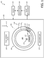
- FIGURE 1 schematically illustrates a hybrid PET / CT scanner 102.
- a detector array 104 includes one or more detector rings 106 arranged with respect to each other along a z-axis. Each detector ring 106 includes an aperture, which surrounds an examination region 108.
- the illustrated detector ring 106 includes at least two layers 110, including an inner layer 110 1 , ..., and an outer layer 110 N , where N is a positive integer.
- the inner and outer layers 110 1 and 110 N respectively are closed rings, concentrically arranged with respect to each other in an x-y plane.
- the detector array 104 and hence the layers 110 1 and 110 N are disposed in a single PET /CT gantry 100.
- the layers 110 include a plurality of modules 112, each module 112 including a plurality of detectors 114, and each detector 114 including a sub-portion of the inner and outer layers 110 1 and 110 N .
- the individual modules 112 are attached to the hybrid PET / CT scanner 102 to construct the detector ring 106.
- a detector 114 includes first and second layer 110 1 and 110 N pixels 116 and 118 configured to detect radiation in a predetermined energy band(s) and generate and output signals indicative thereof.
- the inner layer 110 1 is configured as a single layer that detects both gamma rays and X-rays with the same pixels 116, and the outer layer 110 N is configured to detect only gamma rays with the pixels 118.
- the inner layer 110 1 is activated to detect X-ray radiation.
- both the inner and the outer layers 110 1 and 110 N are activated to detect gamma radiation.
- 511 keV photons photo-electrically attenuated by the inner layer 110 1 and/or energy from Compton scattered gamma rays deposited in the inner layer 110 1 are detected and can be combined with the output from the outer layer 110 N . This may mitigate data loss due to gamma ray absorption in the inner layer 110 1 .
- the outer layer 110 N width can be decreased. Thus, cost can be reduced without loss of PET information.
- the detector array 104 described herein may also reduce manufacturing and/or service complexity and cost relative to a system with separate and independent PET and CT detector modules.
- the detector 114 can be built, assembled into the modules 112, and the whole scanner 102 can be assembled in one facility on one assembly line, which simplifies construction and assembly, providing a logistical advantage.
- the alignment of PET and CT images during registration can be improved as patient movement between PET and CT scans is mitigated, which may also reduce overall scan time.
- An X-ray radiation source 120 is configured to generate and transmit X-ray radiation that traverses the examination region 108.
- X-rays include radiation having an energy in the band from 20 keV to 120 keV.
- the X-ray radiation source 112 can be fixedly or moveably (rotationally and/or translationally) coupled to the scanner 102.
- Gamma radiation is emitted via positron annihilation events during radioactive decay 122 of a radioactive isotope of an agent inside the examination region 108 and traverses the examination region 108.
- Gamma rays include radiation having an energy in the energy band from 120 keV to 520 keV.
- an anti-scatter grid 124 is employed.
- the anti-scatter grid (ASG) 124 is disposed adjacent to a radiation receiving face of the inner layer 110 1
- the anti-scatter grid 124 includes septa with X-ray absorbing material (e.g., lead, tungsten, etc.) that attenuate scatter X-ray radiation.
- the anti-scatter grid 124 is configured as an arc or a closed ring and is moveable (rotationally and/or translationally) or fixed with respect to the examination region 108. In another embodiment, the anti-scatter grid 124 is omitted.
- Signal pre-processing circuitry 126 processes the signal from the detector array 104. For the inner layer 110 1 , this includes energy discriminating and binning the detected gamma and/or X-ray radiation based on a set of predetermined energy thresholds of interest. For example, detected gamma rays can be binned into energy bins such as 120-480 keV and 480-520keV during PET imaging, and detected X-rays can be binned into energy bins such as 0-40 keV, 40-80 keV and 80-120 keV CT during imaging. Other numbers of bins and/or bin widths are contemplated herein.
- the pre-processing circuitry 126 For PET mode, the pre-processing circuitry 126 identifies coincident gamma pairs detected in the outer layer 110 N by identifying photons detected in temporal coincidence (or near simultaneously) along a line of response (LOR) and generates event by event or list mode data indicative thereof.
- the data may also include time-of-flight (TOF) information, which allows the pre-processing circuitry 126 to estimate the location of an event along a LOR.
- TOF time-of-flight
- the pre-processing circuitry 126 extrapolates the position of 511 keV photons detected by the inner layer 110 1 (e.g., from the above example energy bin 480-520 keV) to the corresponding PET pixels in the second layer 1 10 N . Furthermore, the pre-processing circuitry 126, for Compton scattered gamma rays, utilizes the energy information from, e.g., the above example energy bin 120-480 keV, and the corresponding timing to sum Compton split photons back into their original 511 keV energy level. These events are then assigned to the corresponding PET pixels in the second layer 110 N .
- a reconstructor 128 is configured to reconstruct PET and CT volumetric image data and/or images from the detector 104 output.
- PET this includes reconstructing the data the outer layer 110 N along with the PET data from the inner layer 110 1 that was mapped to the outer layer 110 N .
- CT this includes reconstructing data selectively from one or more particular energy bins for spectral (energy dependent) imaging and/or combining the data from all of the CT bins and reconstructing conventional CT image data over the CT energy spectrum.
- the reconstructor 128 can be a single reconstructor or include a PET reconstructor and a CT reconstructor.
- a computer is configured as an operator console 130 and includes a human readable output device such as a monitor or display and an input device such as a keyboard and mouse.
- Software resident on the operator console 130 allows the operator to interact with the hybrid PET/CT scanner 102, e.g., via a graphical user interface (GUI) or otherwise. This interaction may include selecting an imaging mode (e.g., PET mode and/or CT mode), initiating scanning, etc.
- GUI graphical user interface
- a subject support 132 supports a subject or an object in the examination region 108.
- the inner layer 110 1 includes a PET / CT direct conversion material 202, which directly converts absorbed incident gamma and/or X-ray radiation to electrical signals (e.g., voltage or electrical current pulses) having a peak height indicative of the energy of the absorbed incident gamma and/or X-ray radiation.
- a PET / CT direct conversion material 202 which directly converts absorbed incident gamma and/or X-ray radiation to electrical signals (e.g., voltage or electrical current pulses) having a peak height indicative of the energy of the absorbed incident gamma and/or X-ray radiation.
- Examples of a suitable direct conversion material include Cadmium Zinc Telluride (CZT), silicon strips, and/or other materials.
- CZT Cadmium Zinc Telluride
- the attenuation in the PET / CT direct conversion material 202 is quantifiable and set by a thickness of the direct conversion material.
- the outer layer 110 2 includes a PET scintillator 204 optically coupled to a PET photosensor 206.
- suitable scintillation materials for the PET scintillator 204 include lutetium-yttrium oxyorthosilicate (LYSO), Bismuth germanium oxide (BGO), and/or other scintillation material that absorbs 511 keV gamma rays.
- the photosensor 206 is tuned to sense light emitted by the PET scintillator 204 and generates an electrical signal indicative thereof.
- the inner and outer layers 110 1 and 110 2 are fixedly coupled together. In another instance, the inner and outer layers 110 1 and 110 2 are removeably coupled together. With this instance, the individual layers 110 can be separated and independently serviced, which may reduce cost since an entire detector need not be replaced.
- the direct conversion material 202 is coupled to a radiation receiving face of the PET scintillator 204.
- a circuit 208 is electrically coupled to the direct conversion material 202 and the readout electronics 210.
- the circuit 208 routes signals from the direct conversion material 202 to readout electronics 210, which route signals from the inner and outer layers 110 to the signal pre-processing circuitry 116 ( FIGURE 1 ).
- the circuit 208 is disposed along a side of the module 118 that is perpendicular to the gamma ray and X-ray receiving sides of the PET / CT direct conversion material 202 and the PET scintillator 204.
- the signal pre-processor 116 ( FIGURE 1 ) includes an energy-discriminator for the output of the inner layer 110 1 that discriminates the electrical signals from the direct conversion material 202, e.g., with one or more comparators, each having a different predetermined energy threshold value, which corresponds to an energy of interest.
- a counter increments a count value for each threshold in response to the output of the corresponding comparator satisfying the threshold.
- the direct conversion material 202 includes an encapsulate material with particles supporting quantum dots of scintillation material embedded therein.
- the direct conversion material 202 is a single layer with different groups of quantum dots for different energy ranges homogeneously distributed in the encapsulate material.
- the direct conversion material 202 includes multiple layers, each layer including a single group of the quantum dots for a single energy range of the different energy ranges.
- the outer layer 110 2 and the readout electronics 210 are the same as described in connection with FIGURE 2 .
- the inner layer 110 1 includes an indirect conversion structure, which includes a scintillation material 302 optically coupled to a photosensor 304.
- a scintillation material 302 optically coupled to a photosensor 304.
- gamma or X-rays absorbed by the scintillation material 302 are converted to light photons, which are sensed by the photosensor 304, which generates an electrical signal indicative thereof.
- a suitable scintillation material 302 is gadolinium oxysulfide (GOS).
- GOS gadolinium oxysulfide
- LYSO an encapsulate material with particles supporting quantum dots of scintillation material embedded therein such as that described in application s/n 62/202,397, filed August 7, 2015 , and entitled "QUANTUM DOT BASED IMAGING DETECTOR”.
- the photosensor 304 is coupled to a flip chip
- signals are routed from the photosensor 304 through the flip chip to the circuit 208 as described herein and/or otherwise to the readout electronics 210.
- the circuit 208 is disposed along a side of the module 118 as described herein, but other configurations are contemplated herein.
- the inner and outer layers 110 1 and 110 2 are fixedly or removeably coupled together.
- the signal pre-processor 116 ( FIGURE 1 ) includes a pulse shaper that processes the signal (which can first be amplified) from the PET /CT photosensor 304 and generates a pulse (e.g., voltage, current, etc.) indicative of the energy of the detected radiation.
- a pulse e.g., voltage, current, etc.
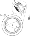
- FIGURES 4 , 5 and 6 schematically illustrate a detector ring 106 in connection with an example X-ray radiation source 120 and the anti-scatter grid 124.
- FIGURE 4 shows a view looking into the aperture of the ring 106 into the examination region 108.
- FIGURES 5 and 6 show side views of the detector ring 106 respectively with the X-ray radiation source 120 and the anti-scatter grid 124 outside of ( FIGURE 5 ) and inside of ( FIGURE 6 ) the examination region 108.
- a carriage or support 402 supports both an X-ray tube 120 and the anti-scatter grid 124.
- the support 402 and hence the X-ray tube 120 and the anti-scatter grid 124 are moveably mounted to the scanner 102 to translate at least between a position 502 ( FIGURE 5 ) outside of the examination region 108 and a position 602 ( FIGURE 6 ) inside of the examination region 108.
- the support 402 and hence the X-ray tube 120 and the anti-scatter grid 124 are also configured to rotate around the examination region 108.
- the support 402 can be coupled in the PET / CT scanner 102 via slide, ball, etc. bearings, and moved between the positions 502 and 602 via a motor and a belt, chain, lead screw, gears, etc.
- a controller would drive the motor based on whether scanner 102 is in PET mode or CT mode. In PET mode, the support 402 is placed at position 502 for PET imaging, and in CT mode, the support 402 is placed at position 602 for CT imaging.
- FIGURES 4-6 are provided to show the X-ray tube 120 and the anti-scatter grid 124 attached to a same support (the same support 402) configured to move out of and into the examination region 108 respectively for PET and CT imaging. It is to be understood the relative size and/or position of the layers 106, the support 402, the X-ray tube 120, and the anti-scatter grid 124 are not limiting.
- FIGURE 7 schematically illustrate a variation where the X-ray radiation source 120 includes solid state x-ray generators 702 1 , 702 2 , 702 3 , 702 4 , ... located in gaps 704 1 , 704 2 , 704 3 , 704 4 , ... between module 118 1 , 118 2 , 118 3 , 118 4 , ...throughout the ring 106.
- the x-ray generators 702 1 , 702 2 , 702 3 , 702 4 , ... are pulsed in sequence to obtain CT data for the full circumference of the ring.
- the anti-scatter grid 124 can be attached to and moved by the support 402 as discussed in connection with FIGURES 4 , 5 and 6 in coordination with activation of the generators 702 1 , 702 2 , 702 3 , 702 4 , ....
- the anti-scatter grid 124 is a full circle and translates between 505 and 602, but does not rotate around the examination region like in FIGURES 4-6 .
- FIGURE 8 illustrates an example method in accordance with an embodiment herein.
- gamma radiation is detected by a first layer and a second layer of a dual layer imaging detector of an imaging system and the first and second layers generate first and second signals indicative thereof.
- the first and second signals are processed, which generates PET image data.
- X-ray radiation is detected by the same first layer of the dual layer imaging detector of the imaging system and the first layer generates third signal indicative thereof.
- the third signals are processed, which generates CT image data.
- the PET and CT image data are combined and displayed.
Description
- The following generally relates to an imaging detector and more particularly to a hybrid positron emission (PET) / computed tomography (CT) imaging detector configured to detect both gamma rays and X-rays with a same detector.
- Positron emission tomography (PET) imaging is a functional imaging modality that generates and displays three-dimensional (3-D) tomographic images of distribution of radioactive isotopes injected into the body. While PET images provide quantitative representations of isotope distribution, they lack structural information about the anatomical structure of the surrounding tissues where the isotope is distributed. Computed tomography (CT) imaging generates 3-D tomographic images with structural information of anatomical tissue. PET and CT images have been combined (e.g., overlaid, fused, etc.) to provide functional information with an anatomical frame of reference.
- PET and CT datasets can be acquired individually with a standalone PET gantry and a standalone CT gantry. PET and CT datasets can also be acquired with a single system that includes both a PET gantry portion and a CT gantry portion. With this configuration, the PET and CT gantry portions are physically spaced apart from each other along the scanning axis and have separate and distinct imaging planes. The PET and CT gantry portions are consecutively employed, moving the subject or object in between scans from one gantry portion to the other, and PET and CT datasets are acquired independently in that the PET dataset is not acquired with the CT gantry portion, and the CT dataset is not acquired with the PET gantry portion.
- Unfortunately, with the above noted configurations, patient movement, voluntary and/or involuntary, between PET and CT scans may result in miss-registration of combined PET and CT images. Furthermore, the patient is moved from one gantry / gantry portion to the other gantry / gantry portion between PET and CT scans, which increases total scan time. Moreover, standalone and connected systems require two separate gantries / gantry portions and supporting hardware for each, each adding to manufacturing and/or service complexity and/or
WO2012/066469 discloses a prior art system according to the preamble ofclaim 1. - Aspects of the present application address the above-referenced matters and others.
- According to one aspect, an imaging system includes a radiation sensitive detector array with at least one ring. The at least one ring includes a first layer configured to detect gamma radiation and X-ray radiation and generate signals indicative thereof and a second layer configured to detect only gamma radiation and generate a signal indicative thereof. The first and second layers are concentric closed rings of the at least one ring. The imaging system further includes a signal pre-processor configured to process the signals indicative of the gamma radiation detected by the first layer, the X-ray radiation detected by the first layer, and the gamma radiation detected by the second layer, wherein the signal pre-processor is configured to bin the gamma radiation detected by the first layer into a predetermined set of PET energy bins based on a predetermined set of PET energy thresholds, and bin the X-ray radiation detected by the first layer into a predetermined set of CT energy bins based on a predetermined set of CT energy thresholds.
- In an embodiment the signal pre-processor is configured to identify a coincident gamma pair along a line of response based on the gamma radiation detected by the second layer. Preferably the signal pre-processor is configured to estimate a location of the coincident gamma pair along the line of response.
- In another aspect, a method includes detecting gamma radiation with a first layer of a dual layer PET / CT detector in response to imaging in PET mode, detecting gamma radiation with a second layer of the dual layer PET / CT detector in response to imaging in PET mode, and generating PET image data with the gamma radiation detected with the first and second layers. The method further includes detecting X-ray radiation with the first layer of the dual layer PET / CT detector in response to imaging in CT mode and generating CT image data with the X-ray radiation detected with the first layer. The method further includes visually displaying the PET image data and the CT image data. The method further includes binning the gamma radiation detected by the first layer into a predetermined set of PET energy bins based on a predetermined set of PET energy thresholds, and binning the X-ray radiation detected by the first layer into a predetermined set of CT energy bins based on a predetermined set of CT energy thresholds. Preferably the method further includes superimposing the CT image data over the PET image data.
- In another aspect, not covered by the claimed invention, an imaging detector array includes at least one ring that includes a plurality of detector modules, each detector module including a plurality of detectors. Each detector includes a first layer having a plurality of first pixels configured to detect gamma radiation and X-ray radiation and generate signals indicative thereof, and a second layer having a plurality of second pixels configured to detect only gamma radiation and generate a signal indicative thereof. The first and second layers are vertically stacked one on top of the other in a direction of incident gamma radiation and X-ray radiation.
- Still further aspects of the present invention will be appreciated to those of ordinary skill in the art upon reading and understanding the following detailed description.
- The invention may take form in various components and arrangements of components, and in various steps and arrangements of steps. The drawings are only for purposes of illustrating the preferred embodiments and are not to be construed as limiting the invention.
-
FIGURE 1 schematically illustrates an example imaging system with a hybrid PET / CT imaging detector. -
FIGURE 2 schematically illustrates an example of a direct conversion based hybrid PET / CT imaging detector. -
FIGURE 3 schematically illustrates an example of a scintillator / photosensor based hybrid PET / CT imaging detector. -
FIGURE 4 schematically illustrates a front view showing a moveable support supporting an X-ray radiation source and anti-scatter grid. -
FIGURE 5 schematically illustrates a side view of the configuration ofFIGURE 4 with the X-ray radiation source and the anti-scatter grid outside of the examination region. -
FIGURE 6 schematically illustrates a side view of the configuration ofFIGURE 4 with the X-ray radiation source and the anti-scatter grid inside of the examination region. -
FIGURE 7 schematically illustrates an example of another configuration of the X-ray source. -
FIGURE 8 illustrates an example method in accordance with an embodiment herein. -
FIGURE 1 schematically illustrates a hybrid PET /CT scanner 102. - A
detector array 104 includes one ormore detector rings 106 arranged with respect to each other along a z-axis. Eachdetector ring 106 includes an aperture, which surrounds anexamination region 108. The illustrateddetector ring 106 includes at least twolayers 110, including aninner layer 1101, ..., and anouter layer 110N, where N is a positive integer. The inner andouter layers detector array 104 and hence thelayers CT gantry 100. - In one instance, the
layers 110 include a plurality ofmodules 112, eachmodule 112 including a plurality ofdetectors 114, and eachdetector 114 including a sub-portion of the inner andouter layers individual modules 112 are attached to the hybrid PET /CT scanner 102 to construct thedetector ring 106. Adetector 114 includes first andsecond layer pixels inner layer 1101 is configured as a single layer that detects both gamma rays and X-rays with thesame pixels 116, and theouter layer 110N is configured to detect only gamma rays with thepixels 118. - For CT imaging, only the
inner layer 1101 is activated to detect X-ray radiation. For PET imaging, both the inner and theouter layers inner layer 1101 and/or energy from Compton scattered gamma rays deposited in theinner layer 1101 are detected and can be combined with the output from theouter layer 110N. This may mitigate data loss due to gamma ray absorption in theinner layer 1101. Furthermore, since theinner layer 1101 contributes to the overall gamma attenuation, theouter layer 110N width can be decreased. Thus, cost can be reduced without loss of PET information. - The
detector array 104 described herein may also reduce manufacturing and/or service complexity and cost relative to a system with separate and independent PET and CT detector modules. For example, thedetector 114 can be built, assembled into themodules 112, and thewhole scanner 102 can be assembled in one facility on one assembly line, which simplifies construction and assembly, providing a logistical advantage. Moreover, the alignment of PET and CT images during registration can be improved as patient movement between PET and CT scans is mitigated, which may also reduce overall scan time. - An
X-ray radiation source 120 is configured to generate and transmit X-ray radiation that traverses theexamination region 108. X-rays include radiation having an energy in the band from 20 keV to 120 keV. As described in greater detail below, theX-ray radiation source 112 can be fixedly or moveably (rotationally and/or translationally) coupled to thescanner 102. Gamma radiation is emitted via positron annihilation events duringradioactive decay 122 of a radioactive isotope of an agent inside theexamination region 108 and traverses theexamination region 108. Gamma rays include radiation having an energy in the energy band from 120 keV to 520 keV. - In the illustrated embodiment, an
anti-scatter grid 124 is employed. The anti-scatter grid (ASG) 124 is disposed adjacent to a radiation receiving face of theinner layer 1101 In one instance, theanti-scatter grid 124 includes septa with X-ray absorbing material (e.g., lead, tungsten, etc.) that attenuate scatter X-ray radiation. As described in greater detail below, theanti-scatter grid 124 is configured as an arc or a closed ring and is moveable (rotationally and/or translationally) or fixed with respect to theexamination region 108. In another embodiment, theanti-scatter grid 124 is omitted. -
Signal pre-processing circuitry 126 processes the signal from thedetector array 104. For theinner layer 1101, this includes energy discriminating and binning the detected gamma and/or X-ray radiation based on a set of predetermined energy thresholds of interest. For example, detected gamma rays can be binned into energy bins such as 120-480 keV and 480-520keV during PET imaging, and detected X-rays can be binned into energy bins such as 0-40 keV, 40-80 keV and 80-120 keV CT during imaging. Other numbers of bins and/or bin widths are contemplated herein. - For PET mode, the
pre-processing circuitry 126 identifies coincident gamma pairs detected in theouter layer 110N by identifying photons detected in temporal coincidence (or near simultaneously) along a line of response (LOR) and generates event by event or list mode data indicative thereof. The data may also include time-of-flight (TOF) information, which allows thepre-processing circuitry 126 to estimate the location of an event along a LOR. - For PET mode, the
pre-processing circuitry 126 extrapolates the position of 511 keV photons detected by the inner layer 1101 (e.g., from the above example energy bin 480-520 keV) to the corresponding PET pixels in thesecond layer 1 10N. Furthermore, thepre-processing circuitry 126, for Compton scattered gamma rays, utilizes the energy information from, e.g., the above example energy bin 120-480 keV, and the corresponding timing to sum Compton split photons back into their original 511 keV energy level. These events are then assigned to the corresponding PET pixels in thesecond layer 110N. - A
reconstructor 128 is configured to reconstruct PET and CT volumetric image data and/or images from thedetector 104 output. For PET, this includes reconstructing the data theouter layer 110N along with the PET data from theinner layer 1101 that was mapped to theouter layer 110N. For CT, this includes reconstructing data selectively from one or more particular energy bins for spectral (energy dependent) imaging and/or combining the data from all of the CT bins and reconstructing conventional CT image data over the CT energy spectrum. Thereconstructor 128 can be a single reconstructor or include a PET reconstructor and a CT reconstructor. - A computer is configured as an
operator console 130 and includes a human readable output device such as a monitor or display and an input device such as a keyboard and mouse. Software resident on theoperator console 130 allows the operator to interact with the hybrid PET/CT scanner 102, e.g., via a graphical user interface (GUI) or otherwise. This interaction may include selecting an imaging mode (e.g., PET mode and/or CT mode), initiating scanning, etc. Asubject support 132 supports a subject or an object in theexamination region 108. -
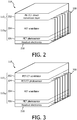
FIGURE 2 schematically illustrates an example of amodule 118 for a two-layer (N=2)ring 106. - The
inner layer 1101 includes a PET / CTdirect conversion material 202, which directly converts absorbed incident gamma and/or X-ray radiation to electrical signals (e.g., voltage or electrical current pulses) having a peak height indicative of the energy of the absorbed incident gamma and/or X-ray radiation. Examples of a suitable direct conversion material include Cadmium Zinc Telluride (CZT), silicon strips, and/or other materials. The attenuation in the PET / CTdirect conversion material 202 is quantifiable and set by a thickness of the direct conversion material. - The
outer layer 1102 includes aPET scintillator 204 optically coupled to aPET photosensor 206. Examples of suitable scintillation materials for thePET scintillator 204 include lutetium-yttrium oxyorthosilicate (LYSO), Bismuth germanium oxide (BGO), and/or other scintillation material that absorbs 511 keV gamma rays. Thephotosensor 206 is tuned to sense light emitted by thePET scintillator 204 and generates an electrical signal indicative thereof. - In one instance, the inner and
outer layers outer layers individual layers 110 can be separated and independently serviced, which may reduce cost since an entire detector need not be replaced. In the illustrated embodiment, thedirect conversion material 202 is coupled to a radiation receiving face of thePET scintillator 204. - A
circuit 208 is electrically coupled to thedirect conversion material 202 and thereadout electronics 210. Thecircuit 208 routes signals from thedirect conversion material 202 toreadout electronics 210, which route signals from the inner andouter layers 110 to the signal pre-processing circuitry 116 (FIGURE 1 ). In this example, thecircuit 208 is disposed along a side of themodule 118 that is perpendicular to the gamma ray and X-ray receiving sides of the PET / CTdirect conversion material 202 and thePET scintillator 204. - With this configuration, the signal pre-processor 116 (
FIGURE 1 ) includes an energy-discriminator for the output of theinner layer 1101 that discriminates the electrical signals from thedirect conversion material 202, e.g., with one or more comparators, each having a different predetermined energy threshold value, which corresponds to an energy of interest. A counter increments a count value for each threshold in response to the output of the corresponding comparator satisfying the threshold. A binner energy-bins the signals and, hence, the detected gamma rays or X-rays multiple energy bins based on the counts. - In a variation, the
direct conversion material 202 includes an encapsulate material with particles supporting quantum dots of scintillation material embedded therein. In one instance, thedirect conversion material 202 is a single layer with different groups of quantum dots for different energy ranges homogeneously distributed in the encapsulate material. In another instance, thedirect conversion material 202 includes multiple layers, each layer including a single group of the quantum dots for a single energy range of the different energy ranges. - An example of a quantum dot direct conversion detector is described in application s/n
62/202,397, filed August 7, 2015 EP 14186022.1, filed September 23, 2014 -
FIGURE 3 schematically illustrates another example of amodule 118 for a two-layer (N=2)ring 106. In this embodiment, theouter layer 1102 and thereadout electronics 210 are the same as described in connection withFIGURE 2 . - In this example, the
inner layer 1101 includes an indirect conversion structure, which includes ascintillation material 302 optically coupled to aphotosensor 304. In general, gamma or X-rays absorbed by thescintillation material 302 are converted to light photons, which are sensed by thephotosensor 304, which generates an electrical signal indicative thereof. - An example of a
suitable scintillation material 302 is gadolinium oxysulfide (GOS). Another example is LYSO, an encapsulate material with particles supporting quantum dots of scintillation material embedded therein such as that described in application s/n62/202,397, filed August 7, 2015 - Where the
photosensor 304 is coupled to a flip chip, signals are routed from the photosensor 304 through the flip chip to thecircuit 208 as described herein and/or otherwise to thereadout electronics 210. Likewise, thecircuit 208 is disposed along a side of themodule 118 as described herein, but other configurations are contemplated herein. Likewise, the inner andouter layers - With this configuration, the signal pre-processor 116 (
FIGURE 1 ) includes a pulse shaper that processes the signal (which can first be amplified) from the PET /CT photosensor 304 and generates a pulse (e.g., voltage, current, etc.) indicative of the energy of the detected radiation. -
FIGURES 4 ,5 and 6 schematically illustrate adetector ring 106 in connection with an exampleX-ray radiation source 120 and theanti-scatter grid 124.FIGURE 4 shows a view looking into the aperture of thering 106 into theexamination region 108.FIGURES 5 and 6 show side views of thedetector ring 106 respectively with theX-ray radiation source 120 and theanti-scatter grid 124 outside of (FIGURE 5 ) and inside of (FIGURE 6 ) theexamination region 108. - In this example, a carriage or
support 402 supports both anX-ray tube 120 and theanti-scatter grid 124. Thesupport 402 and hence theX-ray tube 120 and theanti-scatter grid 124 are moveably mounted to thescanner 102 to translate at least between a position 502 (FIGURE 5 ) outside of theexamination region 108 and a position 602 (FIGURE 6 ) inside of theexamination region 108. Thesupport 402 and hence theX-ray tube 120 and theanti-scatter grid 124 are also configured to rotate around theexamination region 108. - The
support 402 can be coupled in the PET /CT scanner 102 via slide, ball, etc. bearings, and moved between thepositions scanner 102 is in PET mode or CT mode. In PET mode, thesupport 402 is placed atposition 502 for PET imaging, and in CT mode, thesupport 402 is placed atposition 602 for CT imaging. - It is to be appreciated that
FIGURES 4-6 are provided to show theX-ray tube 120 and theanti-scatter grid 124 attached to a same support (the same support 402) configured to move out of and into theexamination region 108 respectively for PET and CT imaging. It is to be understood the relative size and/or position of thelayers 106, thesupport 402, theX-ray tube 120, and theanti-scatter grid 124 are not limiting. -
FIGURE 7 schematically illustrate a variation where theX-ray radiation source 120 includes solid state x-ray generators 7021, 7022, 7023, 7024, ... located in gaps 7041, 7042, 7043, 7044, ... betweenmodule ring 106. The x-ray generators 7021, 7022, 7023, 7024, ... are pulsed in sequence to obtain CT data for the full circumference of the ring. - In one instance, the
anti-scatter grid 124 can be attached to and moved by thesupport 402 as discussed in connection withFIGURES 4 ,5 and 6 in coordination with activation of the generators 7021, 7022, 7023, 7024, .... In a variation, theanti-scatter grid 124 is a full circle and translates between 505 and 602, but does not rotate around the examination region like inFIGURES 4-6 . -
FIGURE 8 illustrates an example method in accordance with an embodiment herein. - It is to be appreciated that the ordering of the below acts is for explanatory purposes and not limiting. As such, other orderings are also contemplated herein. In addition, one or more of the acts may be omitted and/or one or more other acts may be included.
- At 802, gamma radiation is detected by a first layer and a second layer of a dual layer imaging detector of an imaging system and the first and second layers generate first and second signals indicative thereof.
- At 804, the first and second signals are processed, which generates PET image data.
- At 806, X-ray radiation is detected by the same first layer of the dual layer imaging detector of the imaging system and the first layer generates third signal indicative thereof.
- At 808, the third signals are processed, which generates CT image data.
- At 810, the PET and CT image data are combined and displayed.
- The invention has been described herein with reference to the various embodiments. Modifications and alterations may occur to others upon reading the description herein. It is intended that the invention be construed as including all such modifications and alterations insofar as they come within the scope of the appended claims.
Claims (15)
- An imaging system (102), comprising:a radiation sensitive detector array (104) with at least one detector ring (106) including:a first layer (1101) configured to detect gamma radiation and X-ray radiation and generate signals indicative thereof; anda second layer (110N) configured to detect only gamma radiation and generate a signal indicative thereof,wherein the first and second layers are concentric rings of the at least one detector ring; anda signal pre-processor (126) configured to process the signals indicative of the gamma radiation detected by the first layer, the X-ray radiation detected by the first layer, and the gamma radiation detected by the second layer,characterized in that the signal pre-processor is configured to bin the gamma radiation detected by the first layer into a predetermined set of PET energy bins based on a predetermined set of PET energy thresholds, and bin the X-ray radiation detected by the first layer into a predetermined set of CT energy bins based on a predetermined set of CT energy thresholds.
- The imaging system of claim 1, further comprising:
a single gantry, wherein the at least one detector ring with the concentric first and second layers is disposed in the single gantry. - The imaging system of claim 1, further comprising:
a reconstructor (128) configured to reconstruct the processed signals indicative of the gamma radiation detected by the first layer, the X-ray radiation detected by the first layer, and the gamma radiation detected by the second layer and generate positron emission tomography (PET) and computed tomography (CT) image data. - The imaging system of claim 1, wherein the signal pre-processor is configured to extrapolate a position of 511 keV photon in the set of PET energy bins to a corresponding pixel location of the second layer.
- The imaging system of any of claims 1 to 4, wherein the signal pre-processor is configured to utilize energy information from the set of PET energy bins and PET and CT timing information to sum Compton photons absorbed in part in the first layer and in part in the second layer into a 511 keV photon for a corresponding pixel location of the second layer.
- The imaging system of any of claims 1 to 5, wherein the reconstructor is configured to reconstruct the X-ray radiation detected by the first layer from a predetermined one of the set of CT energy bins.
- The imaging system of any of claims 1 to 6, wherein the first layer includes a direct conversion material, wherein the direct conversion material includes Cadmium Zinc Telluride, a plurality of silicon strips, or a solid state garnet.
- The imaging system of any of claims 1 to 6, wherein the first layer includes a direct conversion material, wherein the direct conversion material includes an encapsulate material with quantum dots of scintillation material embedded therein.
- The imaging system of any of claims 1 to 6, wherein the first layer includes a scintillator optically coupled to a photosensor.
- The imaging system of any of claims 1 to 9, further comprising:
an X-ray radiation source (120) configured to move out of an examination region to acquire PET data and into the examination region to acquire CT data. - The imaging system of any of claims 1 to 10, further comprising:
anti-scatter grid (124) configured to move out of an examination region for a PET scan and into the examination region for a CT scan. - A method, comprising:detecting gamma radiation with a first layer of a dual layer PET / CT detector in response to imaging in PET mode;detecting gamma radiation with a second layer of the dual layer PET / CT detector in response to imaging in PET mode;generating PET image data with the gamma radiation detected with the first and second layers;detecting X-ray radiation with the first layer of the dual layer PET / CT detector in response to imaging in CT mode;generating CT image data with the X-ray radiation detected with the first layer; andvisually displaying the PET image data and the CT image data, characterized in that the gamma radiation detected by the first layer is binned into a predetermined set of PET energy bins based on a predetermined set of PET energy thresholds, and the X-ray radiation detected by the first layer is binned into a predetermined set of CT energy bins based on a predetermined set of CT energy thresholds.
- The method of claim 12, further comprising:energy-binning the gamma radiation detected with the first layer in an energy bin including 511 keV; andextrapolating a position of 511 keV photon from the energy-binned the gamma radiation to a pixel location of the second layer.
- The method of any of claims 12 to 13, further comprising:energy-binning the gamma radiation detected with the first layer in an energy bin with a window from 120 keV to 480 keV;identifying split Compton photons absorbed in the first layer based on the energy-binned gamma radiation; andsumming the identified split Compton photon absorbed in the first layer with a remaining portion of the split Compton photon absorbed in the second layer based on timing information for the first and second layers into a 511 keV photon for a pixel in the second layer.
- The method of any of claims 12 to 14, further comprising:energy-binning the X-ray radiation detected with the first layer in a predetermined set of energy bins over an energy range from 10 keV to 120 keV; andselectively reconstructing the energy binned X-ray radiation for at least one of the bins of the set of energy bins.
Applications Claiming Priority (2)
| Application Number | Priority Date | Filing Date | Title |
|---|---|---|---|
| US201562202414P | 2015-08-07 | 2015-08-07 | |
| PCT/IB2016/054493 WO2017025842A1 (en) | 2015-08-07 | 2016-07-28 | Hybrid pet / ct imaging detector |
Publications (2)
| Publication Number | Publication Date |
|---|---|
| EP3332269A1 EP3332269A1 (en) | 2018-06-13 |
| EP3332269B1 true EP3332269B1 (en) | 2020-09-09 |
Family
ID=56738138
Family Applications (1)
| Application Number | Title | Priority Date | Filing Date |
|---|---|---|---|
| EP16753704.2A Active EP3332269B1 (en) | 2015-08-07 | 2016-07-28 | Hybrid pet / ct imaging detector |
Country Status (5)
| Country | Link |
|---|---|
| US (1) | US10247832B2 (en) |
| EP (1) | EP3332269B1 (en) |
| JP (1) | JP6854805B2 (en) |
| CN (1) | CN107923982B (en) |
| WO (1) | WO2017025842A1 (en) |
Families Citing this family (16)
| Publication number | Priority date | Publication date | Assignee | Title |
|---|---|---|---|---|
| ES2629092B1 (en) * | 2015-11-04 | 2018-07-04 | Consejo Superior De Investigaciones Científicas (Csic) | GAMMA RAY COMPTON CAMERA SYSTEM WITH FLIGHT TIME MEASUREMENT |
| US11762107B2 (en) * | 2016-12-21 | 2023-09-19 | Koninklijke Philips N.V. | Protection of a gamma radiation detector with an optical modulator to modulate an amount of transmission between a gamma scintillator array and a first photodetector array |
| US10413256B2 (en) | 2017-09-13 | 2019-09-17 | LiteRay Medical, LLC | Systems and methods for ultra low dose CT fluoroscopy |
| DE102017221924B3 (en) * | 2017-12-05 | 2019-05-02 | Siemens Healthcare Gmbh | Method for merging an analysis data set with an image data record, positioning device and computer program |
| US11500054B2 (en) | 2018-05-17 | 2022-11-15 | Navico Holding As | Marine chart and sonar image presentation systems and methods |
| JP6986487B2 (en) * | 2018-05-17 | 2021-12-22 | 浜松ホトニクス株式会社 | Method of acquiring gamma ray generation position of scattering simultaneous counting in PET apparatus and PET apparatus |
| FR3081231B1 (en) * | 2018-05-18 | 2020-06-12 | Damavan Imaging | GAMMA RADIATION DETECTION IMAGING SYSTEM AND METHOD |
| US11701074B2 (en) * | 2018-08-07 | 2023-07-18 | Siemens Medical Solutions Usa, Inc. | Compton camera with segmented detection modules |
| CN109223014A (en) * | 2018-08-31 | 2019-01-18 | 上海联影医疗科技有限公司 | Obtain method, detector device, medical supply and the storage medium of medical image |
| CN111068186B (en) * | 2018-10-22 | 2021-03-02 | 清华大学 | CT imaging and image-guided radiotherapy device |
| CN111375144B (en) * | 2018-12-29 | 2021-03-05 | 清华大学 | Tomographic and image-guided radiation therapy apparatus |
| WO2020133400A1 (en) | 2018-12-29 | 2020-07-02 | 清华大学 | Tomography and image-guided radiotherapy device |
| WO2020198935A1 (en) * | 2019-03-29 | 2020-10-08 | Shenzhen Xpectvision Technology Co., Ltd. | A method of imaging |
| CN111694046B (en) * | 2020-07-24 | 2022-06-07 | 中国工程物理研究院核物理与化学研究所 | Single-energy gamma device |
| US11921199B2 (en) | 2021-02-19 | 2024-03-05 | Navico, Inc. | Sonar beam footprint presentation |
| US11947007B2 (en) | 2021-02-19 | 2024-04-02 | Navico, Inc. | Sonar beam zone presentation |
Family Cites Families (22)
| Publication number | Priority date | Publication date | Assignee | Title |
|---|---|---|---|---|
| CA2252993C (en) | 1998-11-06 | 2011-04-19 | Universite De Sherbrooke | Detector assembly for multi-modality scanners |
| US7297958B2 (en) | 2001-12-03 | 2007-11-20 | Hitachi, Ltd. | Radiological imaging apparatus |
| JP3851575B2 (en) * | 2002-03-05 | 2006-11-29 | 株式会社日立製作所 | PET inspection equipment |
| JP4093013B2 (en) * | 2002-10-23 | 2008-05-28 | 株式会社日立製作所 | Radiation inspection equipment |
| GB0311881D0 (en) | 2003-05-22 | 2003-06-25 | Univ Aberdeen | A detector module for detecting ionizing radiation |
| DE102004049677B3 (en) * | 2004-10-12 | 2006-06-14 | Siemens Ag | Detector assembly for use in a combined transmission / emission tomography device |
| US20070085010A1 (en) * | 2005-06-14 | 2007-04-19 | The Regents Of The University Of California | Scintillator with a matrix material body carrying nano-material scintillator media |
| US7800070B2 (en) * | 2006-04-10 | 2010-09-21 | Quantum Molecular Technologies, Inc. | Quantum photodetectors, imaging apparatus and systems, and related methods |
| US7545902B2 (en) * | 2006-09-18 | 2009-06-09 | General Electric Company | Received x-ray handling methods and apparatus |
| JP4897881B2 (en) * | 2007-05-15 | 2012-03-14 | 独立行政法人放射線医学総合研究所 | Gamma ray detector and gamma ray reconstruction method |
| US20090059971A1 (en) * | 2007-08-27 | 2009-03-05 | Axsun Technologies, Inc. | Linearized Swept Laser Source for Optical Coherence Analysis System |
| CN101401725B (en) * | 2007-09-27 | 2013-08-21 | 西门子公司 | Patient treatment using a hybrid imaging system |
| CN201365927Y (en) * | 2009-01-21 | 2009-12-23 | 北京亿仁赛博医疗设备有限公司 | PET/CT image fusion combining diagnosis equipment |
| JP5426282B2 (en) * | 2009-09-03 | 2014-02-26 | 株式会社東芝 | Diagnostic imaging equipment |
| RU2578856C2 (en) * | 2010-11-18 | 2016-03-27 | Конинклейке Филипс Электроникс Н.В. | Single-detector positron emission and computer tomography system |
| US20120265050A1 (en) * | 2011-04-04 | 2012-10-18 | Ge Wang | Omni-Tomographic Imaging for Interior Reconstruction using Simultaneous Data Acquisition from Multiple Imaging Modalities |
| EP2806799A1 (en) * | 2012-01-24 | 2014-12-03 | Koninklijke Philips N.V. | Nuclear imaging system |
| RU2014143053A (en) * | 2012-03-27 | 2016-05-20 | Конинклейке Филипс Н.В. | ORDINARY VISUALIZATION BY THE VISUALIZATION SYSTEM CONTAINING DETECTORS FOR PHOTON ACCOUNT |
| CN103961124A (en) * | 2013-01-31 | 2014-08-06 | 北京大基康明医疗设备有限公司 | Combined diagnosis system integrating PET-CT functions |
| US9505977B2 (en) * | 2014-07-30 | 2016-11-29 | The United States of America Department of Energy | Gadolinium-loaded gel scintillators for neutron and antineutrino detection |
| WO2016046216A1 (en) | 2014-09-23 | 2016-03-31 | Philips Lighting Holding B.V. | Encapsulated materials in porous particles |
| US10527739B2 (en) | 2015-08-07 | 2020-01-07 | Koninklijke Philips N.V. | Quantum dot based imaging detector |
-
2016
- 2016-07-28 CN CN201680046429.1A patent/CN107923982B/en active Active
- 2016-07-28 US US15/748,330 patent/US10247832B2/en active Active
- 2016-07-28 JP JP2018506302A patent/JP6854805B2/en active Active
- 2016-07-28 WO PCT/IB2016/054493 patent/WO2017025842A1/en active Application Filing
- 2016-07-28 EP EP16753704.2A patent/EP3332269B1/en active Active
Non-Patent Citations (1)
| Title |
|---|
| None * |
Also Published As
| Publication number | Publication date |
|---|---|
| US10247832B2 (en) | 2019-04-02 |
| JP2018527981A (en) | 2018-09-27 |
| US20180217273A1 (en) | 2018-08-02 |
| CN107923982A (en) | 2018-04-17 |
| JP6854805B2 (en) | 2021-04-07 |
| WO2017025842A1 (en) | 2017-02-16 |
| EP3332269A1 (en) | 2018-06-13 |
| CN107923982B (en) | 2022-01-04 |
Similar Documents
| Publication | Publication Date | Title |
|---|---|---|
| EP3332269B1 (en) | Hybrid pet / ct imaging detector | |
| US6399951B1 (en) | Simultaneous CT and SPECT tomography using CZT detectors | |
| US7332724B2 (en) | Method and apparatus for acquiring radiation data | |
| US6448559B1 (en) | Detector assembly for multi-modality scanners | |
| JP4093013B2 (en) | Radiation inspection equipment | |
| US8059880B2 (en) | Nuclear medicine diagnosis device, form tomography diagnosis device, nuclear medicine data arithmetic processing method, and form tomogram arithmetic processing method | |
| EP3320372B1 (en) | Device and method for simultaneous x-ray and gamma photon imaging with a stacked detector | |
| US20100012845A1 (en) | Energy-resolving detection system and imaging system | |
| Patton et al. | Coincidence imaging with a dual-head scintillation camera | |
| EP2847617B1 (en) | Spect/pet imaging system | |
| US6303935B1 (en) | Combination PET/SPECT nuclear imaging system | |
| CN113287056B (en) | Medical imaging system based on collimator and detector | |
| US20160206255A1 (en) | Hybrid passive/active multi-layer energy discriminating photon-counting detector | |
| JP4737201B2 (en) | Radiation inspection equipment | |
| US11324459B2 (en) | Methods and systems for pet detectors | |
| EP3985416A1 (en) | Combined imaging detector and imaging system | |
| JP2015152356A (en) | Dark countless radiation detection energy discrimination imaging system | |
| KR20220047221A (en) | Sensitivity enhancing method and system for radiation using compton effect |
Legal Events
| Date | Code | Title | Description |
|---|---|---|---|
| STAA | Information on the status of an ep patent application or granted ep patent |
Free format text: STATUS: THE INTERNATIONAL PUBLICATION HAS BEEN MADE |
|
| PUAI | Public reference made under article 153(3) epc to a published international application that has entered the european phase |
Free format text: ORIGINAL CODE: 0009012 |
|
| STAA | Information on the status of an ep patent application or granted ep patent |
Free format text: STATUS: REQUEST FOR EXAMINATION WAS MADE |
|
| 17P | Request for examination filed |
Effective date: 20180307 |
|
| AK | Designated contracting states |
Kind code of ref document: A1 Designated state(s): AL AT BE BG CH CY CZ DE DK EE ES FI FR GB GR HR HU IE IS IT LI LT LU LV MC MK MT NL NO PL PT RO RS SE SI SK SM TR |
|
| AX | Request for extension of the european patent |
Extension state: BA ME |
|
| DAV | Request for validation of the european patent (deleted) | ||
| DAX | Request for extension of the european patent (deleted) | ||
| RAP1 | Party data changed (applicant data changed or rights of an application transferred) |
Owner name: KONINKLIJKE PHILIPS N.V. |
|
| GRAP | Despatch of communication of intention to grant a patent |
Free format text: ORIGINAL CODE: EPIDOSNIGR1 |
|
| STAA | Information on the status of an ep patent application or granted ep patent |
Free format text: STATUS: GRANT OF PATENT IS INTENDED |
|
| INTG | Intention to grant announced |
Effective date: 20200325 |
|
| GRAS | Grant fee paid |
Free format text: ORIGINAL CODE: EPIDOSNIGR3 |
|
| GRAA | (expected) grant |
Free format text: ORIGINAL CODE: 0009210 |
|
| STAA | Information on the status of an ep patent application or granted ep patent |
Free format text: STATUS: THE PATENT HAS BEEN GRANTED |
|
| AK | Designated contracting states |
Kind code of ref document: B1 Designated state(s): AL AT BE BG CH CY CZ DE DK EE ES FI FR GB GR HR HU IE IS IT LI LT LU LV MC MK MT NL NO PL PT RO RS SE SI SK SM TR |
|
| REG | Reference to a national code |
Ref country code: GB Ref legal event code: FG4D |
|
| REG | Reference to a national code |
Ref country code: AT Ref legal event code: REF Ref document number: 1312289 Country of ref document: AT Kind code of ref document: T Effective date: 20200915 Ref country code: CH Ref legal event code: EP |
|
| REG | Reference to a national code |
Ref country code: IE Ref legal event code: FG4D |
|
| REG | Reference to a national code |
Ref country code: DE Ref legal event code: R096 Ref document number: 602016043719 Country of ref document: DE |
|
| REG | Reference to a national code |
Ref country code: LT Ref legal event code: MG4D |
|
| PG25 | Lapsed in a contracting state [announced via postgrant information from national office to epo] |
Ref country code: FI Free format text: LAPSE BECAUSE OF FAILURE TO SUBMIT A TRANSLATION OF THE DESCRIPTION OR TO PAY THE FEE WITHIN THE PRESCRIBED TIME-LIMIT Effective date: 20200909 Ref country code: NO Free format text: LAPSE BECAUSE OF FAILURE TO SUBMIT A TRANSLATION OF THE DESCRIPTION OR TO PAY THE FEE WITHIN THE PRESCRIBED TIME-LIMIT Effective date: 20201209 Ref country code: HR Free format text: LAPSE BECAUSE OF FAILURE TO SUBMIT A TRANSLATION OF THE DESCRIPTION OR TO PAY THE FEE WITHIN THE PRESCRIBED TIME-LIMIT Effective date: 20200909 Ref country code: LT Free format text: LAPSE BECAUSE OF FAILURE TO SUBMIT A TRANSLATION OF THE DESCRIPTION OR TO PAY THE FEE WITHIN THE PRESCRIBED TIME-LIMIT Effective date: 20200909 Ref country code: SE Free format text: LAPSE BECAUSE OF FAILURE TO SUBMIT A TRANSLATION OF THE DESCRIPTION OR TO PAY THE FEE WITHIN THE PRESCRIBED TIME-LIMIT Effective date: 20200909 Ref country code: BG Free format text: LAPSE BECAUSE OF FAILURE TO SUBMIT A TRANSLATION OF THE DESCRIPTION OR TO PAY THE FEE WITHIN THE PRESCRIBED TIME-LIMIT Effective date: 20201209 Ref country code: GR Free format text: LAPSE BECAUSE OF FAILURE TO SUBMIT A TRANSLATION OF THE DESCRIPTION OR TO PAY THE FEE WITHIN THE PRESCRIBED TIME-LIMIT Effective date: 20201210 |
|
| REG | Reference to a national code |
Ref country code: AT Ref legal event code: MK05 Ref document number: 1312289 Country of ref document: AT Kind code of ref document: T Effective date: 20200909 |
|
| REG | Reference to a national code |
Ref country code: NL Ref legal event code: MP Effective date: 20200909 |
|
| PG25 | Lapsed in a contracting state [announced via postgrant information from national office to epo] |
Ref country code: PL Free format text: LAPSE BECAUSE OF FAILURE TO SUBMIT A TRANSLATION OF THE DESCRIPTION OR TO PAY THE FEE WITHIN THE PRESCRIBED TIME-LIMIT Effective date: 20200909 Ref country code: RS Free format text: LAPSE BECAUSE OF FAILURE TO SUBMIT A TRANSLATION OF THE DESCRIPTION OR TO PAY THE FEE WITHIN THE PRESCRIBED TIME-LIMIT Effective date: 20200909 Ref country code: LV Free format text: LAPSE BECAUSE OF FAILURE TO SUBMIT A TRANSLATION OF THE DESCRIPTION OR TO PAY THE FEE WITHIN THE PRESCRIBED TIME-LIMIT Effective date: 20200909 |
|
| PG25 | Lapsed in a contracting state [announced via postgrant information from national office to epo] |
Ref country code: EE Free format text: LAPSE BECAUSE OF FAILURE TO SUBMIT A TRANSLATION OF THE DESCRIPTION OR TO PAY THE FEE WITHIN THE PRESCRIBED TIME-LIMIT Effective date: 20200909 Ref country code: SM Free format text: LAPSE BECAUSE OF FAILURE TO SUBMIT A TRANSLATION OF THE DESCRIPTION OR TO PAY THE FEE WITHIN THE PRESCRIBED TIME-LIMIT Effective date: 20200909 Ref country code: PT Free format text: LAPSE BECAUSE OF FAILURE TO SUBMIT A TRANSLATION OF THE DESCRIPTION OR TO PAY THE FEE WITHIN THE PRESCRIBED TIME-LIMIT Effective date: 20210111 Ref country code: RO Free format text: LAPSE BECAUSE OF FAILURE TO SUBMIT A TRANSLATION OF THE DESCRIPTION OR TO PAY THE FEE WITHIN THE PRESCRIBED TIME-LIMIT Effective date: 20200909 Ref country code: CZ Free format text: LAPSE BECAUSE OF FAILURE TO SUBMIT A TRANSLATION OF THE DESCRIPTION OR TO PAY THE FEE WITHIN THE PRESCRIBED TIME-LIMIT Effective date: 20200909 |
|
| PG25 | Lapsed in a contracting state [announced via postgrant information from national office to epo] |
Ref country code: AT Free format text: LAPSE BECAUSE OF FAILURE TO SUBMIT A TRANSLATION OF THE DESCRIPTION OR TO PAY THE FEE WITHIN THE PRESCRIBED TIME-LIMIT Effective date: 20200909 Ref country code: AL Free format text: LAPSE BECAUSE OF FAILURE TO SUBMIT A TRANSLATION OF THE DESCRIPTION OR TO PAY THE FEE WITHIN THE PRESCRIBED TIME-LIMIT Effective date: 20200909 Ref country code: ES Free format text: LAPSE BECAUSE OF FAILURE TO SUBMIT A TRANSLATION OF THE DESCRIPTION OR TO PAY THE FEE WITHIN THE PRESCRIBED TIME-LIMIT Effective date: 20200909 Ref country code: IS Free format text: LAPSE BECAUSE OF FAILURE TO SUBMIT A TRANSLATION OF THE DESCRIPTION OR TO PAY THE FEE WITHIN THE PRESCRIBED TIME-LIMIT Effective date: 20210109 |
|
| REG | Reference to a national code |
Ref country code: DE Ref legal event code: R097 Ref document number: 602016043719 Country of ref document: DE |
|
| PG25 | Lapsed in a contracting state [announced via postgrant information from national office to epo] |
Ref country code: SK Free format text: LAPSE BECAUSE OF FAILURE TO SUBMIT A TRANSLATION OF THE DESCRIPTION OR TO PAY THE FEE WITHIN THE PRESCRIBED TIME-LIMIT Effective date: 20200909 |
|
| PLBE | No opposition filed within time limit |
Free format text: ORIGINAL CODE: 0009261 |
|
| STAA | Information on the status of an ep patent application or granted ep patent |
Free format text: STATUS: NO OPPOSITION FILED WITHIN TIME LIMIT |
|
| 26N | No opposition filed |
Effective date: 20210610 |
|
| PG25 | Lapsed in a contracting state [announced via postgrant information from national office to epo] |
Ref country code: SI Free format text: LAPSE BECAUSE OF FAILURE TO SUBMIT A TRANSLATION OF THE DESCRIPTION OR TO PAY THE FEE WITHIN THE PRESCRIBED TIME-LIMIT Effective date: 20200909 Ref country code: DK Free format text: LAPSE BECAUSE OF FAILURE TO SUBMIT A TRANSLATION OF THE DESCRIPTION OR TO PAY THE FEE WITHIN THE PRESCRIBED TIME-LIMIT Effective date: 20200909 |
|
| PG25 | Lapsed in a contracting state [announced via postgrant information from national office to epo] |
Ref country code: IT Free format text: LAPSE BECAUSE OF FAILURE TO SUBMIT A TRANSLATION OF THE DESCRIPTION OR TO PAY THE FEE WITHIN THE PRESCRIBED TIME-LIMIT Effective date: 20200909 |
|
| REG | Reference to a national code |
Ref country code: CH Ref legal event code: PL |
|
| PG25 | Lapsed in a contracting state [announced via postgrant information from national office to epo] |
Ref country code: MC Free format text: LAPSE BECAUSE OF FAILURE TO SUBMIT A TRANSLATION OF THE DESCRIPTION OR TO PAY THE FEE WITHIN THE PRESCRIBED TIME-LIMIT Effective date: 20200909 |
|
| REG | Reference to a national code |
Ref country code: BE Ref legal event code: MM Effective date: 20210731 |
|
| PG25 | Lapsed in a contracting state [announced via postgrant information from national office to epo] |
Ref country code: LI Free format text: LAPSE BECAUSE OF NON-PAYMENT OF DUE FEES Effective date: 20210731 Ref country code: CH Free format text: LAPSE BECAUSE OF NON-PAYMENT OF DUE FEES Effective date: 20210731 |
|
| PG25 | Lapsed in a contracting state [announced via postgrant information from national office to epo] |
Ref country code: LU Free format text: LAPSE BECAUSE OF NON-PAYMENT OF DUE FEES Effective date: 20210728 |
|
| PG25 | Lapsed in a contracting state [announced via postgrant information from national office to epo] |
Ref country code: IE Free format text: LAPSE BECAUSE OF NON-PAYMENT OF DUE FEES Effective date: 20210728 Ref country code: BE Free format text: LAPSE BECAUSE OF NON-PAYMENT OF DUE FEES Effective date: 20210731 |
|
| PG25 | Lapsed in a contracting state [announced via postgrant information from national office to epo] |
Ref country code: HU Free format text: LAPSE BECAUSE OF FAILURE TO SUBMIT A TRANSLATION OF THE DESCRIPTION OR TO PAY THE FEE WITHIN THE PRESCRIBED TIME-LIMIT; INVALID AB INITIO Effective date: 20160728 |
|
| PG25 | Lapsed in a contracting state [announced via postgrant information from national office to epo] |
Ref country code: NL Free format text: LAPSE BECAUSE OF NON-PAYMENT OF DUE FEES Effective date: 20200923 Ref country code: CY Free format text: LAPSE BECAUSE OF FAILURE TO SUBMIT A TRANSLATION OF THE DESCRIPTION OR TO PAY THE FEE WITHIN THE PRESCRIBED TIME-LIMIT Effective date: 20200909 |
|
| PGFP | Annual fee paid to national office [announced via postgrant information from national office to epo] |
Ref country code: GB Payment date: 20230725 Year of fee payment: 8 |
|
| PGFP | Annual fee paid to national office [announced via postgrant information from national office to epo] |
Ref country code: FR Payment date: 20230725 Year of fee payment: 8 Ref country code: DE Payment date: 20230726 Year of fee payment: 8 |
|
| REG | Reference to a national code |
Ref country code: DE Ref legal event code: R084 Ref document number: 602016043719 Country of ref document: DE |