JP6854528B2 - Lighting sleeve - Google Patents
Lighting sleeve Download PDFInfo
- Publication number
- JP6854528B2 JP6854528B2 JP2018523488A JP2018523488A JP6854528B2 JP 6854528 B2 JP6854528 B2 JP 6854528B2 JP 2018523488 A JP2018523488 A JP 2018523488A JP 2018523488 A JP2018523488 A JP 2018523488A JP 6854528 B2 JP6854528 B2 JP 6854528B2
- Authority
- JP
- Japan
- Prior art keywords
- sleeve
- hub
- channel
- tip
- semi
- Prior art date
- Legal status (The legal status is an assumption and is not a legal conclusion. Google has not performed a legal analysis and makes no representation as to the accuracy of the status listed.)
- Active
Links
- 239000013307 optical fiber Substances 0.000 claims description 13
- 210000001519 tissue Anatomy 0.000 description 78
- 239000000835 fiber Substances 0.000 description 39
- 238000005520 cutting process Methods 0.000 description 22
- 230000003287 optical effect Effects 0.000 description 18
- 238000000034 method Methods 0.000 description 14
- 230000007246 mechanism Effects 0.000 description 8
- 230000006378 damage Effects 0.000 description 7
- 238000009434 installation Methods 0.000 description 6
- 239000000463 material Substances 0.000 description 6
- 238000005476 soldering Methods 0.000 description 5
- 239000000758 substrate Substances 0.000 description 5
- 206010028980 Neoplasm Diseases 0.000 description 4
- 239000000975 dye Substances 0.000 description 4
- 230000033001 locomotion Effects 0.000 description 4
- 238000000465 moulding Methods 0.000 description 4
- 210000000653 nervous system Anatomy 0.000 description 4
- 230000001954 sterilising effect Effects 0.000 description 4
- 238000004659 sterilization and disinfection Methods 0.000 description 4
- 230000005856 abnormality Effects 0.000 description 3
- 201000010099 disease Diseases 0.000 description 3
- 208000037265 diseases, disorders, signs and symptoms Diseases 0.000 description 3
- 230000000694 effects Effects 0.000 description 3
- 238000004519 manufacturing process Methods 0.000 description 3
- 229910052751 metal Inorganic materials 0.000 description 3
- 239000002184 metal Substances 0.000 description 3
- 238000003860 storage Methods 0.000 description 3
- 238000002560 therapeutic procedure Methods 0.000 description 3
- 238000011282 treatment Methods 0.000 description 3
- ZGXJTSGNIOSYLO-UHFFFAOYSA-N 88755TAZ87 Chemical class NCC(=O)CCC(O)=O ZGXJTSGNIOSYLO-UHFFFAOYSA-N 0.000 description 2
- 230000002159 abnormal effect Effects 0.000 description 2
- 230000008901 benefit Effects 0.000 description 2
- 210000004556 brain Anatomy 0.000 description 2
- 239000004020 conductor Substances 0.000 description 2
- 238000013461 design Methods 0.000 description 2
- 239000003814 drug Substances 0.000 description 2
- 210000003811 finger Anatomy 0.000 description 2
- 238000011065 in-situ storage Methods 0.000 description 2
- 238000007373 indentation Methods 0.000 description 2
- 238000012986 modification Methods 0.000 description 2
- 230000004048 modification Effects 0.000 description 2
- 230000000771 oncological effect Effects 0.000 description 2
- 210000004872 soft tissue Anatomy 0.000 description 2
- 239000007787 solid Substances 0.000 description 2
- 230000001225 therapeutic effect Effects 0.000 description 2
- 238000011269 treatment regimen Methods 0.000 description 2
- 238000003466 welding Methods 0.000 description 2
- 208000003174 Brain Neoplasms Diseases 0.000 description 1
- 241001631457 Cannula Species 0.000 description 1
- OKTJSMMVPCPJKN-UHFFFAOYSA-N Carbon Chemical compound [C] OKTJSMMVPCPJKN-UHFFFAOYSA-N 0.000 description 1
- RYGMFSIKBFXOCR-UHFFFAOYSA-N Copper Chemical compound [Cu] RYGMFSIKBFXOCR-UHFFFAOYSA-N 0.000 description 1
- IAYPIBMASNFSPL-UHFFFAOYSA-N Ethylene oxide Chemical compound C1CO1 IAYPIBMASNFSPL-UHFFFAOYSA-N 0.000 description 1
- 206010019233 Headaches Diseases 0.000 description 1
- 208000026139 Memory disease Diseases 0.000 description 1
- 206010028813 Nausea Diseases 0.000 description 1
- 239000004952 Polyamide Substances 0.000 description 1
- 239000004642 Polyimide Substances 0.000 description 1
- 206010047700 Vomiting Diseases 0.000 description 1
- 238000002679 ablation Methods 0.000 description 1
- 230000009471 action Effects 0.000 description 1
- 239000000853 adhesive Substances 0.000 description 1
- 238000004026 adhesive bonding Methods 0.000 description 1
- 230000001070 adhesive effect Effects 0.000 description 1
- 229910052782 aluminium Inorganic materials 0.000 description 1
- XAGFODPZIPBFFR-UHFFFAOYSA-N aluminium Chemical compound [Al] XAGFODPZIPBFFR-UHFFFAOYSA-N 0.000 description 1
- 229960002749 aminolevulinic acid Drugs 0.000 description 1
- 238000013459 approach Methods 0.000 description 1
- 230000003542 behavioural effect Effects 0.000 description 1
- 238000001574 biopsy Methods 0.000 description 1
- 210000004204 blood vessel Anatomy 0.000 description 1
- 210000005013 brain tissue Anatomy 0.000 description 1
- -1 but not limited to Substances 0.000 description 1
- 230000015556 catabolic process Effects 0.000 description 1
- 230000008859 change Effects 0.000 description 1
- 238000006243 chemical reaction Methods 0.000 description 1
- 208000030251 communication disease Diseases 0.000 description 1
- 239000002131 composite material Substances 0.000 description 1
- 238000001816 cooling Methods 0.000 description 1
- 229910052802 copper Inorganic materials 0.000 description 1
- 239000010949 copper Substances 0.000 description 1
- SBYXRAKIOMOBFF-UHFFFAOYSA-N copper tungsten Chemical compound [Cu].[W] SBYXRAKIOMOBFF-UHFFFAOYSA-N 0.000 description 1
- 208000031513 cyst Diseases 0.000 description 1
- 238000006731 degradation reaction Methods 0.000 description 1
- 230000001066 destructive effect Effects 0.000 description 1
- 230000006866 deterioration Effects 0.000 description 1
- 238000011161 development Methods 0.000 description 1
- 230000018109 developmental process Effects 0.000 description 1
- 229910003460 diamond Inorganic materials 0.000 description 1
- 239000010432 diamond Substances 0.000 description 1
- 238000005265 energy consumption Methods 0.000 description 1
- 238000000605 extraction Methods 0.000 description 1
- 239000006260 foam Substances 0.000 description 1
- 230000037406 food intake Effects 0.000 description 1
- 238000009472 formulation Methods 0.000 description 1
- 230000002068 genetic effect Effects 0.000 description 1
- 229910002804 graphite Inorganic materials 0.000 description 1
- 239000010439 graphite Substances 0.000 description 1
- 231100000869 headache Toxicity 0.000 description 1
- 230000036541 health Effects 0.000 description 1
- 238000005286 illumination Methods 0.000 description 1
- 230000001771 impaired effect Effects 0.000 description 1
- 238000001746 injection moulding Methods 0.000 description 1
- 230000003902 lesion Effects 0.000 description 1
- 230000015654 memory Effects 0.000 description 1
- 239000000203 mixture Substances 0.000 description 1
- 230000008693 nausea Effects 0.000 description 1
- 210000005036 nerve Anatomy 0.000 description 1
- 210000000944 nerve tissue Anatomy 0.000 description 1
- 230000000926 neurological effect Effects 0.000 description 1
- 230000007170 pathology Effects 0.000 description 1
- 230000003863 physical function Effects 0.000 description 1
- 239000004033 plastic Substances 0.000 description 1
- 229920002647 polyamide Polymers 0.000 description 1
- 229920001721 polyimide Polymers 0.000 description 1
- 229920001296 polysiloxane Polymers 0.000 description 1
- 239000011347 resin Substances 0.000 description 1
- 229920005989 resin Polymers 0.000 description 1
- 230000004044 response Effects 0.000 description 1
- HBMJWWWQQXIZIP-UHFFFAOYSA-N silicon carbide Chemical compound [Si+]#[C-] HBMJWWWQQXIZIP-UHFFFAOYSA-N 0.000 description 1
- 229910010271 silicon carbide Inorganic materials 0.000 description 1
- 239000002002 slurry Substances 0.000 description 1
- 206010062261 spinal cord neoplasm Diseases 0.000 description 1
- 230000000087 stabilizing effect Effects 0.000 description 1
- 208000024891 symptom Diseases 0.000 description 1
- 238000002626 targeted therapy Methods 0.000 description 1
- 230000003685 thermal hair damage Effects 0.000 description 1
- 210000003813 thumb Anatomy 0.000 description 1
- 230000035899 viability Effects 0.000 description 1
- 230000008673 vomiting Effects 0.000 description 1
Images


Classifications
-
- A—HUMAN NECESSITIES
- A61—MEDICAL OR VETERINARY SCIENCE; HYGIENE
- A61B—DIAGNOSIS; SURGERY; IDENTIFICATION
- A61B90/00—Instruments, implements or accessories specially adapted for surgery or diagnosis and not covered by any of the groups A61B1/00 - A61B50/00, e.g. for luxation treatment or for protecting wound edges
- A61B90/30—Devices for illuminating a surgical field, the devices having an interrelation with other surgical devices or with a surgical procedure
-
- A—HUMAN NECESSITIES
- A61—MEDICAL OR VETERINARY SCIENCE; HYGIENE
- A61B—DIAGNOSIS; SURGERY; IDENTIFICATION
- A61B17/00—Surgical instruments, devices or methods, e.g. tourniquets
- A61B17/32—Surgical cutting instruments
-
- A—HUMAN NECESSITIES
- A61—MEDICAL OR VETERINARY SCIENCE; HYGIENE
- A61B—DIAGNOSIS; SURGERY; IDENTIFICATION
- A61B17/00—Surgical instruments, devices or methods, e.g. tourniquets
- A61B17/32—Surgical cutting instruments
- A61B17/320016—Endoscopic cutting instruments, e.g. arthroscopes, resectoscopes
- A61B17/32002—Endoscopic cutting instruments, e.g. arthroscopes, resectoscopes with continuously rotating, oscillating or reciprocating cutting instruments
-
- A—HUMAN NECESSITIES
- A61—MEDICAL OR VETERINARY SCIENCE; HYGIENE
- A61B—DIAGNOSIS; SURGERY; IDENTIFICATION
- A61B90/00—Instruments, implements or accessories specially adapted for surgery or diagnosis and not covered by any of the groups A61B1/00 - A61B50/00, e.g. for luxation treatment or for protecting wound edges
- A61B90/30—Devices for illuminating a surgical field, the devices having an interrelation with other surgical devices or with a surgical procedure
- A61B90/35—Supports therefor
-
- A—HUMAN NECESSITIES
- A61—MEDICAL OR VETERINARY SCIENCE; HYGIENE
- A61B—DIAGNOSIS; SURGERY; IDENTIFICATION
- A61B17/00—Surgical instruments, devices or methods, e.g. tourniquets
- A61B17/32—Surgical cutting instruments
- A61B17/3205—Excision instruments
- A61B17/3207—Atherectomy devices working by cutting or abrading; Similar devices specially adapted for non-vascular obstructions
- A61B17/320758—Atherectomy devices working by cutting or abrading; Similar devices specially adapted for non-vascular obstructions with a rotating cutting instrument, e.g. motor driven
-
- A—HUMAN NECESSITIES
- A61—MEDICAL OR VETERINARY SCIENCE; HYGIENE
- A61B—DIAGNOSIS; SURGERY; IDENTIFICATION
- A61B17/00—Surgical instruments, devices or methods, e.g. tourniquets
- A61B17/32—Surgical cutting instruments
- A61B17/3205—Excision instruments
- A61B17/3207—Atherectomy devices working by cutting or abrading; Similar devices specially adapted for non-vascular obstructions
- A61B17/320783—Atherectomy devices working by cutting or abrading; Similar devices specially adapted for non-vascular obstructions through side-hole, e.g. sliding or rotating cutter inside catheter
-
- A—HUMAN NECESSITIES
- A61—MEDICAL OR VETERINARY SCIENCE; HYGIENE
- A61B—DIAGNOSIS; SURGERY; IDENTIFICATION
- A61B17/00—Surgical instruments, devices or methods, e.g. tourniquets
- A61B2017/0046—Surgical instruments, devices or methods, e.g. tourniquets with a releasable handle; with handle and operating part separable
-
- A—HUMAN NECESSITIES
- A61—MEDICAL OR VETERINARY SCIENCE; HYGIENE
- A61B—DIAGNOSIS; SURGERY; IDENTIFICATION
- A61B90/00—Instruments, implements or accessories specially adapted for surgery or diagnosis and not covered by any of the groups A61B1/00 - A61B50/00, e.g. for luxation treatment or for protecting wound edges
- A61B90/30—Devices for illuminating a surgical field, the devices having an interrelation with other surgical devices or with a surgical procedure
- A61B2090/306—Devices for illuminating a surgical field, the devices having an interrelation with other surgical devices or with a surgical procedure using optical fibres
-
- A—HUMAN NECESSITIES
- A61—MEDICAL OR VETERINARY SCIENCE; HYGIENE
- A61B—DIAGNOSIS; SURGERY; IDENTIFICATION
- A61B90/00—Instruments, implements or accessories specially adapted for surgery or diagnosis and not covered by any of the groups A61B1/00 - A61B50/00, e.g. for luxation treatment or for protecting wound edges
- A61B90/30—Devices for illuminating a surgical field, the devices having an interrelation with other surgical devices or with a surgical procedure
- A61B2090/309—Devices for illuminating a surgical field, the devices having an interrelation with other surgical devices or with a surgical procedure using white LEDs
Description
関連出願の相互参照
本出願は、2015年11月11日に出願された米国仮特許出願第62/253,957号明細書の利益を主張するとともに、2016年11月10日に出願された米国仮特許出願第15/348,575号明細書の利益をも主張するものであり、それらの開示全体が参照により本明細書に組み込まれる。
Cross-reference to related applications This application claims the benefits of US Provisional Patent Application No. 62 / 253,957 filed on November 11, 2015, and the United States filed on November 10, 2016. It also claims the benefits of Provisional Patent Application No. 15 / 348,575, the entire disclosure of which is incorporated herein by reference.
本開示は、手術部位を照明するためのシステムおよび方法に関する。 The present disclosure relates to systems and methods for illuminating surgical sites.
神経系を含む、身体系の種々の異常は、それらに苦しめられる患者に対する重大な健康リスクの原因となる可能性がある。例えば、神経系に関連して、脳腫瘍および脊髄腫瘍、嚢胞、病変または神経血腫のなどの異常は、運動能力の悪化、悪心または嘔吐、記憶またはコミュニケーション障害、行動変化、頭痛あるいは発作の原因となる可能性がある。ある特定の場合では、異常な組織塊の摘出が必要となる。しかしながら、異常が見出され得る種々の身体機能の種々の複雑さおよび重要性を考慮すると、そのような処置は、極めて繊細な処置である場合があり、非常に正確かつ慎重に実施しなければならない。 Various abnormalities of the physical system, including the nervous system, can pose a significant health risk to patients suffering from them. For example, in relation to the nervous system, abnormalities such as brain and spinal cord tumors, cysts, lesions or neurohematoma cause impaired motor skills, nausea or vomiting, memory or communication disorders, behavioral changes, headaches or attacks. there is a possibility. In certain cases, removal of abnormal tissue mass is required. However, given the varying complexity and importance of the various physical functions in which abnormalities can be found, such procedures can be extremely delicate and must be performed very accurately and carefully. It doesn't become.
健常組織から異常組織を切除するための種々の組織除去システムが知られているかまたは提案されている。しかしながら、多くの既知の組織切断装置は、周囲組織だけでなく除去すべき組織にも損傷を与えずに神経組織を正確かつ自動的に除去できないという欠点がある。こうした組織の撹乱は、破断、破壊の形態をとる可能性があるか、または更には、周囲の側副組織および構造に対する「牽引」もしくは引っ張りの形態をとる可能性があり、周囲組織に意図しない損傷を与える可能性がある。追加的に、種々の他の組織除去システムは、基質および側副組織だけでなく切除された組織にも損傷を与え得る、焼灼エネルギー、破壊エネルギーもしくは熱エネルギー、またはこれらの組み合わせを使用する。更に、いくつかの従来技術の装置はまた、各摘出サイクル間に各組織試料を除去せずに組織試料の連続的な切除をもたらすことができない。 Various tissue removal systems for removing abnormal tissue from healthy tissue are known or proposed. However, many known tissue cutting devices have the disadvantage that they cannot accurately and automatically remove nerve tissue without damaging not only the surrounding tissue but also the tissue to be removed. Such tissue perturbations can take the form of breakage, destruction, or even "traction" or pulling on the surrounding collaterals and structures and are unintended to the surrounding tissue. May cause damage. In addition, various other tissue removal systems use ablation energy, destructive energy or thermal energy, or a combination thereof that can damage not only the substrate and collateral tissue but also the excised tissue. Moreover, some prior art devices also cannot result in continuous excision of the tissue sample without removing each tissue sample during each excision cycle.
周囲組織への損傷はまた、個別化医療レジメンに対するインサイチュ組織による送達および摂取のための「受容体床」でもある、疾患組織が切除される基質に損傷を与える可能性がある。加えて、多くの既知の装置は、迅速に、臨床的に重要な構造または組織に近接する大量の組織の「大部分を除去する」ように、かつ制御を可能にしながら、血管、神経、および健常組織などの、より繊細な構造上または構造周囲の細胞層を層毎に細かく切削できるように構成されていない。それゆえ、従来技術の装置は、大抵の神経学的処置で必要とされる、1つの器具としての融通性に欠けている。実際に、多くの従来技術の装置は、単に、疾患組織を患者から除去する引き剥がしまたは引き裂き作用をもたらす。いくつかの従来技術の器具は切削による組織除去が可能であるが、これらの器具は、焼灼エネルギー源により電力供給される。よって、これらの組織除去機構は、個別化医療レジメンの処方に対して後に使用するために組織の完全性および生存性が保持されることが望まれる場合での使用には好適ではない。組織除去機構では、摘出された組織の無菌環境内での捕捉および保存も可能ではない。追加的に、これらの装置が発生させる焼灼エネルギーはまた、腫瘍が摘出された基質などの、側副組織にも影響を与え、これにより、基質が、損傷を受けて、その後のインサイチュの個別化医療レジメンに対する「受容体床」としてそれほどまたは更には全く有効でなくなる。 Damage to surrounding tissue can also damage the substrate from which the diseased tissue is excised, which is also the "receptor bed" for delivery and ingestion by the in-situ tissue to the personalized medical regimen. In addition, many known devices quickly "remove most" of large amounts of tissue in close proximity to clinically significant structures or tissues, and allow control, while allowing blood vessels, nerves, and tissues. It is not configured to allow finely cutting layer-by-layer cell layers on or around more delicate structures, such as healthy tissues. Therefore, prior art devices lack the flexibility of a single instrument required for most neurological procedures. In fact, many prior art devices simply provide a tearing or tearing action that removes diseased tissue from the patient. While some prior art instruments are capable of cutting tissue removal, these instruments are powered by a cauterizing energy source. Therefore, these tissue removal mechanisms are not suitable for use in cases where tissue integrity and viability are desired to be preserved for later use in the formulation of personalized medical regimens. Tissue removal mechanisms also do not allow capture and storage of excised tissue in a sterile environment. In addition, the cauterizing energy generated by these devices also affects collateral tissues, such as the substrate from which the tumor was removed, which damages the substrate and subsequently personalizes the in situ. It is less or even less effective as a "receptor bed" for medical regimens.
ある特定の疾患に対する現在進化している治療プロトコルでは、患者特定の標的療法、すなわち個別化医療が必要となる。個別化医療のいくつかの形態では、患者特定の疾患の特定の遺伝子構造および分子構造に加えて、疾患の一般的な種類に関する情報を得るために、患者からの疾患組織、すなわち切除された組織が利用される。この情報から、患者自身の組織の使用を必要とする、標的または個別化腫瘍学的治療レジメンが開発されてもよく、この患者自身の組織は、その患者に対する症状に合わせた特定の治療レジメンとして患者に再び送達され得る患者特定の「カクテル療法」を作成するために培養され使用される。 Currently evolving treatment protocols for certain diseases require patient-specific targeted therapies, or personalized medicine. In some forms of personalized medicine, diseased tissue from the patient, i.e. excised tissue, to obtain information about the general type of disease, as well as the specific genetic and molecular structure of the patient-specific disease. Is used. From this information, a targeted or personalized oncological treatment regimen that requires the use of the patient's own tissue may be developed, and this patient's own tissue may be used as a specific treatment regimen tailored to the patient's symptoms. It is cultured and used to create a patient-specific "cocktail therapy" that can be redelivered to the patient.
従来技術の組織切断装置に関する現時点での課題は、人為的な圧潰がほとんどまたは全くない、患者の組織の無傷なセグメント(単なる細胞または浸軟組織ではなく、生検品質組織)を研究室に提供するために安全かつ有効な肉眼的全摘出(GTR)またはほぼGTRを達成する能力である。摘出された組織の「刺傷」の大きさが一貫していることも課題である。同じかまたはほぼ同じ大きさの寸法で摘出された組織の刺傷は、腫瘍学的使用および培養のための処理後の取り扱いを最小限にする。細胞または浸軟組織のスラリーは、組織培養が必要である場合に、病理学にはあまり有用でなく、また有効な腫瘍学に基づく治療プロトコルには許容されない。現在の摘出技術および摘出装置は、必要なものを有効に送達しない。 The current challenge with prior art tissue cutting equipment is to provide the laboratory with intact segments of patient tissue (biopsy quality tissue, not just cells or soft tissue) with little or no artificial crushing. Because of the ability to achieve safe and effective gross total excision (GTR) or near GTR. It is also an issue that the size of the “stab” of the excised tissue is consistent. Tissue stings removed with the same or approximately the same size minimize post-treatment handling for oncological use and culture. Slurries of cells or soft tissues are less useful for pathology when tissue culture is required and are not acceptable for effective oncology-based therapeutic protocols. Current extraction techniques and devices do not effectively deliver what is needed.
外科医により摘出され、病理学者により解析され、かつ腫瘍学で使用される組織は重要情報源であり、その同じ組織が、使用すべき適切に有効な治療プロトコルを患者自身の組織から作成するために使用される。実際には、手術で摘出された組織は、患者の腫瘍の特定の特性と、腫瘍が反応すると期待される特定の療法と、更には患者の腫瘍構造により予測される所与の療法に対する拒絶反応の特定のリスクを定めるために必要とされる一般的情報、プロテオーム情報および分子情報とを所有している。 Tissue removed by a surgeon, analyzed by a pathologist, and used in oncology is an important source of information for the same tissue to create a properly effective treatment protocol from the patient's own tissue to use. used. In practice, surgically removed tissue is rejected by the particular characteristics of the patient's tumor, the particular therapy the tumor is expected to respond to, and even the given therapy predicted by the patient's tumor structure. Possess general information, proteomeal information and molecular information needed to determine a particular risk of.
したがって、組織試料にかかる有害なストレスを排除しないにせよ劣化を最小限に抑えながら、摘出された組織の有効な輸送を提供するシステムに加えて、前述の問題に対処する組織切断装置を利用するシステムの必要性が生じている。 Therefore, in addition to a system that provides effective transport of excised tissue while minimizing degradation, if not eliminating the harmful stress on the tissue sample, a tissue cutting device that addresses the aforementioned problems is utilized. There is a need for a system.
組織除去システムは、ハンドピースと上部ハウジングとを含むとともに、組織を切断するための外側カニューレ開口を有する外側カニューレを備えるように構成された組織除去装置と、外側カニューレ内に配置されるとともに外側カニューレ内を往復移動可能な内側カニューレと、外側カニューレ上に少なくとも部分的に配設されたスリーブを有する照明装置と、開口を画定するとともにスリーブからずらして配設された光ファイバチャネルと、チャネル内に配設されるとともに開口から手術部位に光を供給するように構成された光源とを含み得る。 The tissue removal system includes a handpiece and an upper housing, as well as a tissue removal device configured to include an outer cannula having an outer cannula opening for cutting tissue, and an outer cannula located within the outer cannula. An inner cannula that can reciprocate within, a lighting device with a sleeve that is at least partially disposed on the outer cannula, an optical fiber channel that defines an opening and is offset from the sleeve, and within the channel. It may include a light source that is arranged and configured to supply light from the opening to the surgical site.
組織除去システム用の照明装置は、組織除去システムの外側カニューレ上に少なくとも部分的に配設されたスリーブであって、先端スリーブ開口において手術部位に光を提供するための、かつ組織除去システムに選択的に取り付けられてスリーブを内部に保持するための光源を含むスリーブを含み得る。 The luminaire for the tissue removal system is a sleeve that is at least partially disposed on the outer cannula of the tissue removal system to provide light to the surgical site at the tip sleeve opening and is the choice for the tissue removal system. It may include a sleeve that includes a light source for being mounted and holding the sleeve inside.
組織除去システム用の光学取付組立体は、組織除去システムの外側カニューレ上に少なくとも部分的に配設されたスリーブであって、光ファイバケーブルを含むスリーブと、光ファイバケーブルに光を提供するように構成された光源を含むハウジングであって、光源への暴露を防止するために光源を取り囲むケージを含むハウジングとを含み得る。 An optical mounting assembly for a tissue removal system is a sleeve that is at least partially disposed on the outer cannula of the tissue removal system to provide light to the sleeve, including the optical fiber cable, and to the optical fiber cable. A housing that includes a configured light source, which may include a housing that includes a cage that surrounds the light source to prevent exposure to the light source.
ここで、本開示の実施形態について、例として添付の図面を参照しながらより詳細に説明する。 Here, an embodiment of the present disclosure will be described in more detail with reference to the accompanying drawings as an example.
ここで、後に続く論述を参照し、図面を更に参照すると、開示のシステムおよび方法に対する例示的な手法が詳細に示されている。図面はいくつかの可能な手法を表しているが、図面は必ずしも原寸に比例したものではなく、ある特徴は、本開示をより良く図示し解説するために誇張され、取り除かれ、または部分的に断面にされている場合がある。更に、本明細書に記載の説明は、網羅的であること、またはさもなければ、図面に示しかつ以下の詳細な説明に開示する正確な形態および構成に特許請求の範囲を限定または制限することを意図するものではない。 Here, with reference to the discussion that follows and further reference to the drawings, exemplary approaches to the disclosed systems and methods are shown in detail. Although the drawings represent some possible techniques, the drawings are not necessarily proportional to full size and certain features are exaggerated, removed, or partially to better illustrate and illustrate the disclosure. It may be cross-sectioned. Moreover, the description herein is exhaustive, or otherwise limits or limits the claims to the exact form and configuration shown in the drawings and disclosed in the detailed description below. Is not intended.
本明細書では、手術用途に適した組織切断装置について説明する。脊椎および脳組織の除去などの、脳神経外科手術用途に関連して本明細書で説明されているが、本明細書の開示が他の手術用途および治療プロトコルに適用可能であることが理解される。本明細書で説明するように、装置は、手術部位に光を供給し、典型的には非局所的な光源によりもたらされる陰影効果を低減し、かつ手術部位の特定の領域に特定の波長の光を提供するように構成された照明装置で構成されてもよい。照明装置は、外側カニューレの周囲に配設されたスリーブと、外側カニューレの基端部に配設すべき取付ハブとを含み得る。発光ダイオード(LED)などの、1つまたは複数の光源は、手術部位に光を提供するためのスリーブの先端部に配設されてもよい。光源はまた、スリーブの先端部に露出した光ファイバケーブルの形態であってもよい。 This specification describes a tissue cutting device suitable for surgical use. Although described herein in relation to neurosurgical applications such as spinal and brain tissue removal, it is understood that the disclosures herein are applicable to other surgical applications and therapeutic protocols. .. As described herein, the device supplies light to the surgical site, reducing the shadow effect typically caused by non-local light sources, and at a particular region of the surgical site at a particular wavelength. It may be configured with a lighting device configured to provide light. The illuminator may include a sleeve disposed around the outer cannula and a mounting hub to be disposed at the proximal end of the outer cannula. One or more light sources, such as light emitting diodes (LEDs), may be disposed at the tip of a sleeve to provide light to the surgical site. The light source may also be in the form of a fiber optic cable exposed at the tip of the sleeve.
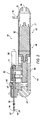
図1を参照すると、組織切断装置40は、ハンドピース42と外側カニューレ44とを含む。例示的な一実施形態において、ハンドピース42は、略円筒形状であり、かつ好ましくは片手で把持されるような大きさおよび形状とされる。ハンドピース42は、基端セクション46と先端セクション48とを備える下部ハウジング50を含む。下部ハウジング50は、モータハウジング71に接続される最も基端側のハウジング部分82(図2および図3)と、モータハウジング71に接続されるカムハウジング69とを備える。前部ハウジングセクション51は、カムハウジング69に接続される。外側カニューレを支持する上部ハウジング52も設けられる。組織採取器58は、直接または適切な管路を介して遠隔で、上部ハウジング52に動作可能に接続されてもよい。ハンドピース42に対して外側カニューレ44(図2および図3)を回転させるための回転ダイヤル60もまた、上部ハウジング52に装着される。
Referring to FIG. 1, the
図2および図3で最も良く分かるように、外側カニューレ44は、開口基端部45と、閉鎖先端部47と、先端部47に近接する先端開口49とを含む。組織切断装置40は、外側カニューレ内腔(図示せず)内に部分的に配置される内側カニューレ76を更に備える。内側カニューレ76は、外側カニューレ管腔内を往復移動するように、かつ人為的な圧潰または熱損傷なしに、外側カニューレ先端開口49を介して外側カニューレ44に入る組織試料を切断するように構成される。内側カニューレ76は、図2に描かれている基端位置と図3に描かれている先端位置との間を往復移動する。内側カニューレ76は、開口基端部77と開口先端部79とを含む。先端部79は、組織を切断するように構成され、かつ例示的な実施形態では、脳または脊椎からの神経系組織などの神経系組織を切断することが可能である。例示的な一実施形態において、内側カニューレ先端部79は、鋭い円形先端を形成して組織切断を容易にするために径方向内方向に面取りされる。外側カニューレ44は、ハンドピース42の長手方向軸線の方向に沿ったハンドピース42に対する外側カニューレ44の位置が固定されたままであるようにハンドピース42に対して並進可能でなくてもよい。
As best seen in FIGS. 2 and 3, the
例示の照明装置402は、図1に示されており、ハンドピース42に選択的に取り付け可能であってもよい。照明装置402は、外側カニューレ44の周囲に配設され、かつスリーブ410のリップまたは先端側面408上に配設された1つまたは複数の光源406により手術部位に光を供給するように構成されてもよい。先端側面408は、スリーブ410の先端部から径方向外方に延びてもよい。先端側面408は、光源406を保持するように構成された1つまたは複数の突出部を形成してもよい。先端側面408はまた、図6および図7に関して以下に描かれ説明されているように、中実リップを形成してもよい。光源406は、外側カニューレ44の先端部47の方にまたは先端部47に光を向けるまたは放射するために、先端側面408の裏面に配設されてもよい。
The
スリーブ410は、外側カニューレ44を取り囲むように構成された管状チャネルを形成してもよい。スリーブ410は、光源406に電力を提供するように構成された可撓性回路基板を含むか、または可撓性回路基板で構成されてもよい。スリーブ410は、取付ハブ416に接続された細長いチャネルセクション412を有し得、それにより、チャネルセクション412が取付ハブ416から離れるように先端側に延びる。照明装置402は、照明装置402が外側カニューレ44の長さに沿って選択的に位置決め可能であり得る図1に設置状態で示されている。設置時に、取付ハブ416およびチャネルセクション412は、外側カニューレの先端部47において外側カニューレ44上に摺動させてもよい。取付ハブ416は、外側カニューレ44に沿った種々の箇所に照明装置402を位置決めするために外側カニューレ44を把持できる摩擦要素を含み得る。
The
スリーブ410は、剛性または半剛性であってもよく、かつエチレンオキシド滅菌、Sterrad、オートクレーブ滅菌およびガンマ線照射滅菌などの、滅菌技術と共に使用するのに好適である材料で作製されてもよい。スリーブは、樹脂と金属とを含み得、かつプリント回路基板(PCB)と同様の材料で形成されてもよい。スリーブ410は、製造時に基板が湾曲して管状形状をなし得るような可撓性PCBであってもよい。更に、スリーブ410は、PCBに加えて、またはPCBに代えて、いくつかの材料で作製されてもよい。一例において、PCBは、ポリマー材料、ポリイミド、ポリアミドなどで取り囲まれるか、またはこれらと重ね合わされてもよい。可撓性スリーブ410は、以下の図7および図10に関して本明細書でより詳細に論じられる。
The
図1を参照すると、取付ハブ416は、設置時に外側カニューレ44を受け入れるための内部チャネル(図示せず)を含み得る。取付ハブ416はまた、スリーブ410の少なくとも一部分を受け入れるように構成されたスリーブチャネル420を含み得る。スリーブ410および取付ハブ416は、接着剤、機械的締結具、ならびに溶着およびはんだ付けなどの他の機構を含む様々な方式で接続されてもよい。加えて、スリーブ410は、チャネルセクション412およびハブ416を単一片として一体に成形することなどにより、ハブ416と一体に形成されてもよい。
With reference to FIG. 1, the mounting
取付ハブ416は、取付ハブ416に、続いてスリーブ410に電力を提供するように構成されたコード426に接続されてもよい。コード426は、ハブ416内のスリーブ410に直接接続されてもよく、それにより、コード426がスリーブ410に電力を直接供給してもよい。この例において、ハブ416は、コード426とスリーブ410との接続を維持および保護するための構造を提供してもよい。別の例において、ハブ416は、電力が接続を通じて伝送されるように、コード426との電気的接続を提供しかつスリーブ410との別の電気的接続を提供してもよい。ハブ416は、ハブ416がコード426を受け入れるコード開口(図1には表示せず)を提供してもよい。
The mounting
取付ハブ416は、外側カニューレ44に適用されるようにかつ外側カニューレ44から取り外されるように構成されてもよい。ハブ416は、外側カニューレ44への種々の形態の固定を提供してもよい。例えば、ハブ416は、図12に関して以下に論じるように、カニューレ44もしくはハブ1116上にクランプするかまたはカニューレ44もしくはハブ1116に摩擦嵌めをもたらしてもよい。他の例において、ハブ416は、クランプ、ロックおよびピンなどの、機械的取付具により外側カニューレ44に締結してもよい。他の例において、取付ハブ416は、上部ハウジング52に取り付けられてもよい。
The mounting
取付ハブ416はまた、スリーブ410を外側カニューレ44の長さに沿って位置決めするためにスリーブ410を外側カニューレ44に沿って摺動させているときなどにハブ416を把持する使用者の能力を高める外面特徴部を含み得る。一例では、長手方向に配向された複数の溝が、ハブ416の外周(図示せず)に互いに間隔をおいて配置され、把持を容易にするために設けられる。別の例では、軸方向に配向された突出する複数の突条(図示せず)が設けられ、ハブ416の外周に間隔をおいて配置される。
The mounting
コード426は、種々のクリップまたはコネクタ(図1には図示せず)によりハンドピース42に沿って保持されてもよい。スイッチ428が、電源(図示せず)との接続を開閉するためにコード426上に配設されてもよく、それにより、コード426を介してスリーブ410に電力を選択的に提供する。スリーブ410への電力を開閉することにより、電力がまた光源406に対しても開閉される。別の例において、電力は、ハンドピース42から、またはハンドピース42に電力を提供するコンソールから直接供給されてもよい。
The
一例では、スリーブ410が設置状態において外側カニューレ44上にあるときに、外側カニューレ44をスリーブ410に対して回転させてもよい。例示的な一例において、外科医は、ハブ416の回転移動を抑制するために片方の手の指でハブ416を把持し、外側カニューレ開口49の周方向位置を調整するためにもう片方の手の親指および/または指で外側カニューレ回転ダイヤル60を回転させてもよい。スリーブ410が外側カニューレ44と共に回転するように構成され得る一方で、多くの場合、コード426がねじれるのを防止するためにスリーブ410の周方向の向きを維持することが好ましい。
In one example, the
図2〜図3では、視認し易くするためにスリーブ410は示されていない。モータ62は、ハンドピース42の基端側の下部ハウジングセクション46内に配置され、かつ外側カニューレ管腔内での内側カニューレ76の往復移動を駆動するために内側カニューレ76に動作可能に接続される。モータ62は、往復動モータまたは回転モータであってもよい。加えて、モータは電気または油圧モータであってもよい。しかしながら、図2および図3の実施形態では、モータ62は回転モータであり、このモータの回転により内側カニューレ76が外側カニューレ管腔内を往復移動する。
In FIGS. 2 to 3, the
モータ62は、モータハウジング71内に収納され、このモータハウジング71は、基端側の下部ハウジングセクション46の一部分を画定する。モータ62は、モータ62の回転運動を内側カニューレ76の並進運動に変換するために使用される内側カニューレ駆動組立体に接続される。モータハウジング71の基端部において、モータハウジング71は、図3の例示的な実施形態では、小穴として構成される、電力ケーブルポート84とホースコネクタ43とを含む、最も基端側のハウジング部分82に接続される。しかしながら、ホースコネクタ43が他の構成を具現化し得ることが理解される。ホースコネクタ43は、真空システムホースをハンドピース42に確実に保持するための機構を提供し、それにより、組織採取器58に真空が供給されることを可能にする。追加的または代替的に、コード426はまた、ホースコネクタ43内にしっかりと固定されてもよい。
The motor 62 is housed in a
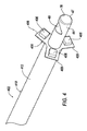
図4は、図1の照明装置402の詳細図を図示している。解説したように、照明装置402は、基端部と先端側面408との間に延びるチャネルセクション412を有するスリーブ410を含む。先端側面408は、光源406の1つを保持するように各々構成される、複数の突出部409を含む。先端側面408は、組織試料を切断するために外側カニューレ開口49がアクセス可能であり得る、外側カニューレ44の先端部47に近接して配設されてもよい。光源406は、手術部位に光を提供してもよい。光源406は、発光ダイオード(LED)または他の低エネルギー消費の光源406であってもよい。LEDは、特に注意を散漫にさせずにまたは他の外部の室内照明に影響を及ぼさずに、特定の手術部位に標的照明を提供してもよい。図4における例は、各突出部409に光源406が配設された3つの突出部409を有する先端側面408を図示している。しかしながら、任意の数の突出部409および光源406が実装されてもよい。
FIG. 4 illustrates a detailed view of the
図5は、図4の照明装置402の上面図を図示している。突出部409は、スリーブ410を貫通して延びる軸線に対して約90°の角度で配向されるものとして図示されているが、突出部は他の角度で配向され得ることが理解される。例えば、実施形態において、突出部409は、LEDからの光を集束させるためにスリーブを貫通して延びる軸線に向けて角度付けされてもよい。
FIG. 5 shows a top view of the
図6は、別の例示の照明装置402を図示している。図6の例において、先端側面408は、複数の光源406を保持するように構成された中実の円形リップを形成する。図6は6つの光源406を図示しているが、これは単に例示的なものに過ぎず、より多いまたはより少ない光源が含まれることがある。
FIG. 6 illustrates another
図7は、図6の照明装置402の上面図を図示している。
FIG. 7 shows a top view of the
図8は、先端側面408が、単一の光源406を保持するように構成された単一の突出部を含む、別の例示の照明装置402を図示している。単一の光源406が示されているが、2つ以上の光源406が単一の突出部409上に含まれてもよい。
FIG. 8 illustrates another
図9は、図8の照明装置402の上面図を図示している。
FIG. 9 shows a top view of the
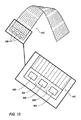
図10は、スリーブ410がPCBから形成される、例示のスリーブ410を未設置状態で図示している。PCBは、電源(図示せず)から光源406に電力を供給するために、種々の導電性トラックを含み得る。スリーブ410の製造時に、光源406は、PCBの裏面に接着され(例えば、はんだ付けされ)てもよい。PCBは、光源406の間のミシン目線504に沿って穿孔されてもよい。次いで、PCBは、その両端部が接続機構(例えば、はんだ付け、溶着、接着、外部クランプなど)により互いに接続または接着された、管状形状に巻かれてもよい。PCBが巻かれるときに、光源406を収納する部分が、ミシン目線504において互いに分離し始めてもよく、これにより、図1および図4に示すように、先端側面408を形成する。次いで、突出部は、形成されたチャネルセクション412に対して、直交する、ほぼ直交するまたは他の所望の角度をなすように外方に屈曲させてもよい。先端側面ハウジングの裏面における光源406は、スリーブ410の先端部において外方に面する。スリーブ410は、単一のPCB片から形成されてもよく、これにより、簡単な製造工程を可能にする。
FIG. 10 illustrates an
解説したように、光源406は、電源(例えば、壁コンセント電源または外部バッテリ電源またはハンドピースもしくはハンドピースコンソール)により電力供給されてもよい。コード426がハブ416に電力を送ってもよく、ハブ416がスリーブ410に電力を送ってもよい。光源406は、一例では、白色光源を含み得る。他の例において、光源406は、異なる光周波数の1つまたは複数の組み合わせを放射するように構成されてもよい。使用時に、種々の色素(例えば、Gliolan(商標)などの5−アミノレブリン酸塩酸塩)が組織に適用されてもよい。外因性源(色素もしくは類似物)などにより誘起されるかまたは組織内で内因的に生じる蛍光特性の種類に応じて、光の波長を変化させてもよい。望ましい光周波数の種類は、色素との適切な反応を生じさせるために使用される色素の種類に依存し得る。
As described, the
光周波数は、スイッチ428において選択されてもよい。一例において、スイッチは、光強度を調整するように構成されたダイヤルを含み得、ここで、ダイヤルは、スリーブ410に、続いて光源406に供給される電力量を調整してもよい。電力量の調整は、交流スイッチまたは可変抵抗器を使用して達成されてもよい。追加的または代替的に、スイッチ428は、電力を制御するための、回転スイッチまたはロッカースイッチなどの多位置スイッチを含み得る。電圧は、光周波数を変更するためにLED内の周波数固有のダイオードだけでなく、光の強度も制御するように構成されてもよい。
The optical frequency may be selected on the
図11は、ハンドピース1142を含む別の例示の組織切断装置1140を図示している。図11はまた、ハンドピース1142に選択的に取り付け可能であり得る別の例示の照明装置1102を図示している。照明装置1102は、外側カニューレ44(図11では視認できない)の周囲に配設され、かつスリーブ1110上に配設された1つまたは複数の光ファイバ装置1112を介して手術部位に光を供給するように構成されてもよい。スリーブ1110は、外側カニューレ44を取り囲むように構成された管状チャネルを形成してもよい。光ファイバ装置1112は、外側カニューレ44の先端部において手術部位に光を供給するように構成された少なくとも1つの光ファイバケーブル(図示せず)を保持するように構成された光ファイバチャネル1108を含み得る。光ファイバケーブルは、ハブ1116内からチャネル1108の端部を貫通して延び、手術部位に光を送ってもよい。スリーブ1110およびチャネル1108は、成形、はんだ付け、熱収縮などにより接続されてもよい。一例において、光ファイバチャネル1108は、光ファイバケーブルであってもよい。つまり、別個のチャネルは必要でないことがあり、代わりに光ファイバケーブルがスリーブ1110に直接接着されてもよい。
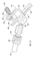
FIG. 11 illustrates another exemplary
取付ハブ1116は、ハンドピース1142の上部ハウジング1152において外側カニューレ44から着脱されるように構成されてもよい。取付ハブ1116は、上部ハウジング1152の一部分上に「スナップ嵌合」するように構成されてもよい。図12で最も良く分かるように、取付ハブ1116は、上部ハウジング1152に選択的に取り付けられるように構成されたハブ本体1118を含み得る。本明細書で論じる例において、ハブ本体1118は、上部ハウジング1152の先端部におけるリム1154の周りでのスナップ嵌合により上部ハウジング1152に接続するように構成されてもよい。ハブ本体1118は、ハブ1116の先端部1156から突出先端部1162に延びる少なくとも1つの突出部を含み得る。本明細書において例に示すように、少なくとも1つの突出部は、第1の突出部1158と第2の突出部1160とを含み得る。
The mounting
第1の突出部1158は、図12に示すように、棒状形状または円筒状形状を含み得る。第2の突出部1160は、直方体状の形状を含み得、かつテーパ状端部1166を含み得る。テーパ状端部1166は、リップ1162を形成するように構成された凹状形状を含み得る。設置状態では、テーパ状端部1166は、リップ1162を介して取付ハブ1116を上部本体1152にしっかりと固定するためにリム1154に係合するように構成されてもよい。
The
取付ハブ1116は、プラスチック、金属など、またはこれらの任意の組み合わせなどの、剛性または半剛性の材料で作製されてもよい。取付ハブ1116は、射出成形により形成されてもよく、かつ単一片として形成されてもよい。追加的または代替的に、取付ハブ1116は、図17および図19に関して以下により詳細に説明するように、第1の部分1202と第2の部分1204とを含み得る。
The mounting
ハブ本体1118はその内部にスリーブ1110を保持するために比較的剛性であり得る一方で、突出部1158、1160は、リム1154上を摺動させながら外方に撓むようにかつ設置状態において後退してリム1154の裏面に係合するように可撓性であってもよい。つまり、テーパ状端部1166がリム1154上で外方に拡開し、次いで、取付ハブ1116を上部本体1152にしっかりと固定するためにリップ1162がリム1154の裏面に係合し得るようにリム1154が外された時点でテーパ状端部1166が内方に後退してよい。
The
取付ハブ1116は、スリーブ1110および光ファイバチャネル1108を受け入れるように構成されてもよく、スリーブ1110および光ファイバチャネル1108の各々は、以下で論じるように、取付ハブ1116内のそれぞれのチャネル内にはんだ付けまたは成形されてもよい。
The mounting
取付ハブ1116はまた、第1の突出部1158および第2の突出部1160の向こう側でこれらの反対側に配設されたワイヤ収納部分1168を含み得る。図13に関して以下により詳細に説明する、ワイヤ収納部分1168は、チャネル開口1172を画定してもよい。図12に示すように、取付ハブは、スリーブ1110を上部分1152上に保持する。ワイヤ収納部分1168は、リム1154の少なくとも一部分を含む、上部ハウジング1152の少なくとも一部分に当接してもよい。少なくとも第2の突出部1160は、リム1154の裏側に係合してもよく、これにより、リム1154への対抗力を生じさせる。それゆえ、ワイヤ収納部分1168および突出部1158、1160は、リム1154に対して力を付与し、リム1154の周囲に摩擦嵌めをもたらしてもよい。
The mounting
ここで図13を参照すると、取付ハブ1116の斜視断面図が示されている。取付ハブ1116は、第3の突出部1170を含み得る。第3の突出部1170は、上で説明したように、第1の突出部1158の形状を模したものであってもよい。ハブ本体1118は、取付ハブ1116の先端部1156から基端部1176まで貫通して延びるスリーブチャネル1174を画定してもよく、かつ各それぞれの端部1156、1176に開口を形成してもよい。これらの開口は、本明細書では、第1のスリーブ開口1184および第2のスリーブ開口1186と称されることがある。スリーブチャネル1174は、ハブ本体1118内にスリーブ1110の少なくとも一部分を保持するように構成されてもよい。
Here, referring to FIG. 13, a perspective sectional view of the mounting
取付ハブ1116はまた、ワイヤチャネル1180を含み得る。ワイヤチャネルは、ワイヤ収納部分1168における、第1のチャネル開口1172とも称される、チャネル開口1172からハブ本体まで延び、かつ取付ハブ1116の先端部1156に第2のチャネル開口1178を画定してもよい。第2のチャネル開口1178は、第2のスリーブ開口1186に隣接して配設されてもよい。
The mounting
ワイヤチャネル1180は、チャネル1180内に少なくとも1本のワイヤまたはケーブルを保持するように構成されてもよい。光装置1190は、ワイヤチャネル1180に沿って配設されてもよい。光装置1190は、(図11に示すように)光チャネル1108の少なくとも一部分を供給または照明するように構成された光源を含み得る。ここで図14を参照すると、ワイヤチャネル1180は、第1のチャネル1192と第2のチャネル1194とを含み得る。第1のチャネル1192は、第1のチャネル開口1172と光装置1190との間に配設されてもよく、かつ電源から光装置1190にワイヤ(例えば、コード426)を提供するように構成されてもよい。第2のチャネル1194は、光装置1190と第2のチャネル開口1178との間に画定されてもよく、かつスリーブ1110の先端部に照明を送るように構成された、光ファイバケーブルを保持するように構成されてもよい。
The
LEDは、特に注意を散漫にさせずにまたは他の外部の室内照明に影響を及ぼさずに、光ファイバ装置1112を介して特定の手術部位に標的照明を提供してもよい。図14には図示されていないが、1つまたは複数の光ファイバ装置1112は、光ファイバチャネル1108内に保持されてもよい。チャネル1108は、第2のチャネル開口1178内に配設されてもよい。光ファイバチャネル1108は、光ファイバ装置1112が光源1206に当接またはほぼ当接するように配設されてもよい。
LEDs may provide targeted lighting to a particular surgical site via
図15は、別の例示の取付ハブ116の斜視断面図を図示している。取付ハブ1116は、(図16に示すように)光源1206の少なくとも一部分を取り囲むように構成された光誘導装置1510を含み得る。光誘導装置1510は、取付部分1512に向けて光を反射または集束させるように構成された反射鏡またはレンズであってもよい。光誘導装置1510は、光源1206を取り囲むように構成されかつ光源1206により生成された光を取付部分1512に反射するように構成された円錐状の金属片を含み得る。取付部分1512は、光ファイバ装置1112が着座する第2のチャネル1194内の箇所であってもよい。つまり、光源1206からの光の全てを光ファイバ装置1112の端部に集束させてもよい。
FIG. 15 illustrates a perspective sectional view of another exemplary mounting hub 116. The mounting
図17Aおよび図18は、図11の照明装置の一部分の斜視図を図示している。図17Bは、図17Bのスリーブ1110およびチャネル1108の断面図である。スリーブ1110および光ファイバチャネル1108は、取付ハブ1116の先端部において受け入れられてもよい。第2の突出部1160およびワイヤ収納部1168は、照明装置1102を設置状態に保持するためにリム1154を把持する。照明装置1102を取り外すために、使用者は、テーパ状端部1166において第2の突出部1160をリム1154から引き離し、これにより、テーパ状端部1166により及ぼされた力が解放され、ワイヤ収納部分1168をリップ1162から離れる方向に摺動させることが許容される。
17A and 18 show perspective views of a portion of the lighting device of FIG. FIG. 17B is a cross-sectional view of the
更に、組立時に、第1の部分1202は、(図13に示すように)電源ワイヤ、光ファイバケーブル、光源(例えば、LED)をワイヤチャネル1180内に受け入れてもよい。これらの構成要素が適切に配置された時点で、第2の部分1204が、第1の部分1202上にスナップ嵌合されてもよい。そして、手術部位では、ハブ1116がリム1154上にスナップ嵌合されてもよい。別の例では、2つの部分1202、1204が、上部ハウジング1152の一部分を包囲するように互いにスナップ嵌合されてもよい。つまり、底部分(例えば、第1の部分1202)が、リップの周囲で上部ハウジング1152の底部に配置され、続いて、頂部分(例えば、第2の部分1204)が、上部ハウジング1152の上に配置され、底部分上にスナップ嵌合されてもよい。
Further, during assembly, the
スリーブ1110および光ファイバチャネル1108はまた、2つの部分の組み立て前にそれぞれのチャネル内に配置されてもよい。一例において、スリーブ1110は、外側カニューレ44の先端部において外側カニューレ44を覆うように挿入されてもよい。次いで、第1の部分1202は、上部ハウジング1152のリム1154の下に配置されてもよく、それにより、スリーブ1110および光ファイバチャネル1108が、それぞれ第2のスリーブ開口1186および第2のチャネル開口1178により受け入れられる。その後、第2の部分1204は、リム1154の上に配設され、かつ第1の部分1202上にスナップ嵌合されてもよい。
The
図19は、図19に示すような、少なくとも1つの第1の突出部1958または複数の第1の突出部1958を有する別の例示の取付ハブ1916を図示している。ハブ1916は、ケーブル送り出し装置1920を含み得る。ケーブル送り出し装置1920は、光ファイバケーブルまたは他のケーブルを受容するように、かつスリーブ1910上に配設された光チャネル1908にケーブルを挿入するのを補助するように構成された中空円筒状形状を有し得る。ケーブル送り出し装置1920は、先端部1930と基端部1932とを有し得る。
FIG. 19 illustrates another
ハブ1916は、送り出し装置1920の基端部1932からケーブルを受け取るように構成された内部チャネル1922を画定してもよい。チャネル1922は、送り出し装置1920の基端部1932からハブの先端部1956における光チャネル1908の基端部1934まで延びてもよく、これにより、光チャネル1908内へのケーブルの送り出しを容易にする。
ハブ1916は、ハブ1916をハンドピース42に取り付けるように構成された取付機構1960を含み得る。取付機構1960は、第2の突出部1958に少なくとも1つのピン1962を含み得る。ピン1962は、ねじ状の螺旋突条1966を含み得る。第2の突出部1958は、ピン1962を受け入れて係合するように構成された縁の隆起した孔1964を画定してもよい。ピン1962は、孔1964に対して選択的に螺合および螺脱されてもよい。孔1964へのピン1962の螺合時に、ピン1962が(図11に示すような)リムに当接し、リム1154に摩擦係合して、ピン1962を介して力を加えることによりリム1154においてハブ1916をハンドピース42に保持するのを補助してもよい。
The
ねじ状装置として示されているが、ピン1962はまた、静止状態にあるときにリム1154に対して力を加えるばねピンであってもよい。ピン1962は、リム1154に加えられた力を解放するためにばね(図示せず)の張力に抗して引き戻されてもよい。
Although shown as a threaded device, the
図20は、図19のハブ1916の別の図を図示しており、それにより、送り出し装置1920が分解状態で示されている。送り出し装置1920は、第1の部分1970と第2の部分1972とを含み得る。第1の部分1970は、ハブ1916に近接してもよく、かつ内部チャネル1922に係合されるように構成されてもよい。第1の部分1970は、本体部分1973と、本体部分1973から延びる第1の突出部1974とを含み得る。第1の突出部1974は、第1の端部1978にリップ1976を含み得る。第1の突出部1974は、第1の直径D1を画定する中空の第1の突出チャネル1971を画定してもよい。本体部分1973は、テーパ状チャネル1975を含み得、ここで、テーパ状チャネル1975は、第1の突出チャネル1971に対して開放しており、かつ本体チャネル1977に向かって先細りになっている。本体チャネル1977は、第1の突出チャネル1971の第1の直径D1よりも小さい第2の直径D2を画定してもよい。
FIG. 20 illustrates another view of the
第2の部分1972は、第2の端部1982に第2の突出部1980を含み得、それにより、第2の突出部1980は、第1の部分1970の第1の突出部1974により受け入れられるように構成されてもよい。第2の突出部1980は、第3の直径D3を有する第2の突出チャネル1981を画定してもよい。第3の直径D3は、第2の突出部1980が設置状態において第1の部分1970の第1の突出部1974により受けられるように構成され得るように、第1の直径D1よりも小さくてもよい。第2の部分1972は、図19に示すように、設置状態において第1の突出部1974を周方向に取り囲むように構成された外側キャップ1984を更に含み得る。送り出し装置1920の先端部1930は、第4の直径D4を画定してもよい。第4の直径D4は、第3の直径D3よりも大きくてもよく、第2の部分1972の内側にテーパコーン状の第2のチャネル1986を形成する。コーン状チャネル1986は、送り出し装置1920内におよび送り出し装置1920を通してワイヤを案内するのを補助してもよい。
The
設置状態において、第1の部分1970のリップ1978は、第2の部分1972のキャップ1984により受け入れられてもよく、かつキャップ1984と第2の突出部1980との間にロック嵌めを形成してもよい。ロック嵌めは、リップ1976をキャップ1984内にスナップ嵌合または螺合することによりもたらされてもよい。図19および図20に例として示すように、キャップ1984は、キャップ1984内に螺旋突条を含み得る。リップ1976は、螺旋突条1990によりキャップ1984内に螺合されるように構成されてもよい。
In the installed state, the
弁1992は、第1の突出チャネル1971内に含まれてもよい。弁1992は、軸方向と径方向の両方向に可撓性を有するように構成された円筒状シリコーンリングであってもよい。弁1992は、光ファイバケーブルを送り出し装置1920のチャネル内にしっかりと固定するように構成されてもよい。キャップ1984の螺合の時点で、第2の突出部1980が第1の突出チャネル1971に押し込まれてもよい。第2の突出部1980は、キャップ1984が螺合されるときに弁に当接して弁1992に圧力を加えてもよい。第2の突出部1980により生じる軸方向の押し込みに応答して、弁1992は、軸方向の押し込みを補償するために径方向内方に延びてもよい。弁1992は、チャネル内にケーブルを保持してケーブルの移動を防止するために、第1の突出チャネル1971内のケーブルに対する挟み込み効果をもたらしてもよい。したがって、第1の部分1970および第2の部分1972が互いに螺合されるときに、弁1992は、ケーブルの外径に固定保持部を形成する。一例において、Tuohy Borst(商標)継手は、送り出し装置1920用に使用されてもよい。
The
追加的または代替的に、Tuohy Borst(商標)継手は第1の部分1970の本体部分1973に固定されてもよく、かつ第2の部分1972は設計から除外されてもよい。この実施態様では、弁1992も除外されてもよい。更に、別の実施態様では、第1の突出部1974が除外されてもよい。したがって、Tuohy Borst(商標)継手は、固定されているが調整可能な箇所に光ファイバケーブルを保持するように構成されてもよい。
Additional or alternative, the Tuohy Borst ™ joint may be secured to the
1つまたは複数のケーブルは、送り出し装置1920の第2の部分1972の先端部1930に挿入されてもよい。ケーブルは、第2のチャネル1986を通して、次に続いて第1の突出チャネル1971を通して、そして本体チャネル1977内に送り出されてもよい。チャネルの直径は、内部チャネル1922内に、続いて光チャネル1908内にケーブルを送り出す目的で、送り出し装置1920の先端部1930から基端部1932に至るまで漸進的に減少してもよい。したがって、ケーブルは、先端部1930においてより幅広のチャネルに容易に挿入され、何の障害もなしにかつチャネル内で座屈せずにより小さな光チャネル1908に押し通されてもよい。
One or more cables may be inserted into the
よって、手術部位に光を供給するための低プロファイル照明装置が本明細書において開示される。陰影の効果を低下させるために、または手術部位における所望の光がない領域に光を提供するために、アドオン装置を単独でまたは他の外部光源に加えて使用してもよい。その上、標的光は、特定の外科的要求に基づいて供給されてもよく、かつ種々の処置の種類に対してカスタマイズ可能であってもよい。 Thus, a low profile illuminator for supplying light to the surgical site is disclosed herein. Add-on devices may be used alone or in addition to other external light sources to reduce the effect of shading or to provide light to areas of the surgical site where there is no desired light. Moreover, the target light may be supplied based on specific surgical requirements and may be customizable for different types of procedures.
図21は、ハンドピース2142を含む別の例示の組織切断装置2140を図示している。図21はまた、外側カニューレ44(図21には図示せず)の周囲に配設されるとともに、スリーブ2110上に配設された光ファイバケーブルを形成する1つまたは複数の光ファイバを介して手術部位に光を供給するように構成され得る、別の例示の照明装置2102を図示している。スリーブ2110は、外側カニューレ44を取り囲むように構成された管状チャネルを形成してもよい。光ファイバ装置1112は、外側カニューレ44の先端部において手術部位に光を供給するように構成された少なくとも1つの光ファイバケーブル(図示せず)を保持するように構成された光ファイバチャネル2108を含み得る。光ファイバケーブルは、ハブ2116内からチャネル2108の端部を貫通して延び、手術部位に光を送ってもよい。スリーブ2110およびチャネル2108は、成形、はんだ付け、熱収縮などにより接続されてもよい。一例において、光ファイバチャネル2108は、光ファイバケーブルであってもよい。つまり、別個のチャネルは必要でないことがあり、代わりに光ファイバケーブルがスリーブ2110に直接接着されてもよい。
FIG. 21 illustrates another exemplary
取付ハブ2116は、ハンドピース2142の上部ハウジング2152において外側カニューレ44から着脱されるように構成されてもよい。図11の取付ハブ1116について上に記載した説明と同様の、取付ハブ2116は、上部ハウジング2152の一部分上に「スナップ嵌合」するように構成されてもよい。
The mounting
図22Aおよび図22Bを参照すると、取付ハブ2116は、上部ハウジング2152に選択的に取り付けられるように構成された円筒状または半円筒状本体2118を含み得る。本明細書で論じる例において、本体2118は、上部ハウジング2152の先端部における先端部2153の周りで上部ハウジング2152に接続するように構成されてもよい。ハブ2116は、ハブ2116が設置位置にあるときに上部ハウジング2152の先端部を覆うように構成された端部キャップ2160を形成してもよい。円筒状本体2118は、キャップ2160から延びて、先端部2153の少なくとも一部分を覆ってもよい。本体2118は、先端部2153の約50%の周囲に延び、先端部2153の一部分を露出したままにしてもよい。
With reference to FIGS. 22A and 22B, the mounting
ハブ2116は、先端部2153を中心に回転可能であってもよい。一例において、ハブ2116は、ハブ2116の内面上にトラック(図示せず)を画定してもよい。トラックは、トラックがリムの周りを移動可能でありハブ2116が上部ハウジング2152を中心に回転可能であることを許容し得る先端部2153を受け入れるように構成されてもよい。
The
図22Aおよび図22Bに示すように、円筒状本体2118は、先端部2153の一部分の周囲に延び、露出部分を残してもよい。露出部分は、ハブ2116がハンドピース2142に当接せずにハブ2116が上部ハウジング2152を中心に回転することを可能にしてもよい。各端部の縁部2144において、円筒状本体2118は、ハンドピース2142に当接し、ハブ2116が更に回転するのを防止してもよい。したがって、ハブ2116は、第1の縁部(例えば、図22Aの縁部2144)がハンドピース2142に当接する第1の位置と、第2の縁部(例えば、縁部2144の端部とは反対側の端部)がハンドピース2142に当接する第2の位置との間で回転してもよい。ハブ2116は、露出部分によりある程度の回転が許容されてもよい。露出部分が大きくかつ円筒状本体2118が小さいほど、ハブ2116の回転度が大きくなる。一例において、ハブ2116は、120度の回転を有し得る。また、より多いまたはより少ない回転が許容されてもよい。
As shown in FIGS. 22A and 22B, the
ハブ2116が回転可能であることに加えて、ハブ2116はまた、上部ハウジング2152に対して固定された箇所に配設されてもよい。上部ハウジング2152へのハブ2116の取り付けに関する更なる詳細については、以下の図26〜図28に関して本明細書で説明する。
In addition to the
ハブ2116は、キャップ2160に配設されたガイド部分2146を含み得る。ガイド部分2146は、光ファイバチャネル2108を受け入れて保持するように構成されたガイドトラック2148を画定してもよい。チャネル2108は、ガイドトラック2148からスリーブ2110に沿って延びてもよい。ハブ2116が上部ハウジング2152に対して回転可能である例では、ガイドトラック2148は、そうしたハブ2116の回転時にチャネル2108をガイドトラック2148内に保持してもよい。
The
図21を参照すると、組織切断装置2140はまた、チャネル2108に光ファイバケーブルまたはワイヤ(図示せず)を提供する光学取付組立体2230を含む。光学取付組立体2230は、LEDなどの光源(図示せず)を収納するように構成されたハウジング2232を含み得る。
Referring to FIG. 21,
再び図23を参照すると、ハウジング2232は、光源(複数可)(図示せず)を含み得る。ハウジング2232はまた、ヒートシンク2240と、ヒートシンク2240を取り囲むケージ2242とを含み得る。ヒートシンク2240は、組織切断装置2140の先端部に熱が送られないように、光源により生じた熱を吸収するように構成されてもよい。光源は、手術部位に光を提供してもよい。光源は、発光ダイオード(LED)または他の低エネルギー消費の光源406を含む、光源406と同様であってもよい。光源はまた、図11の光装置1190と同様であってもよく、かつ光ファイバチャネル2108の少なくとも一部分を供給または照明するように構成された光源を含み得る。
With reference to FIG. 23 again,
ヒートシンク2240は、限定されるものではないが、銅、アルミニウム、グラファイト発泡体、ダイヤモンド、例えば、銅−タングステン擬合金、炭化ケイ素、ダイマロイ、ベリリウム−酸化ベリリウムなどの複合材料、またはこれらの任意の組み合わせを含む、熱伝導性材料で作製されてもよい。ヒートシンク2240は、熱が光源から放散することを可能にするように構成され、これにより、熱破壊による光源発光の劣化または不良を防止してもよい。ケージ2242は、ヒートシンク2240の周りに配設されてもよく、かつ1つまたは複数の開口2246を画定してもよい。開口2246は、ヒートシンク2240の大気暴露を増大させるためにヒートシンク2240の一部分を露出させ、これにより、冷却を更に容易にしてもよい。ケージ2242は、非熱伝導性材料で形成されてもよく、かつ電源などの他の構成要素に加えて光源により生じた熱に使用者が接触するのを防止してもよい。
The
ケージ2242は、スリーブ2110においてケージ2242をハンドピース2142に取り付けるように構成されたクランプ2248を含み得る。クランプ2248はまた、他のチャネル、カニューレ、ラインなどを含むハンドピース2142の他の部分に接続してもよい。クランプ2248は、設置位置においてスリーブ2110および真空ライン2212または他のラインもしくはカニューレの周囲に選択的に接続するように構成されてもよい。ケージ2242を含む、クランプ2248は、クランプ2248がスリーブ2110に対して係脱するように拡径されかつ設置位置でスリーブ2110上にクランプするように内方に付勢されることを可能にする、曲げ易いが剛性の材料で作製されてもよい。
The
光学取付組立体2230は、ハンドピース2142上に配設されたケーブル送り出し装置2220に接続するように構成されたコネクタ2260を含み得る。コネクタ2260は、ハウジング2232、またはケージ2242および/またはヒートシンク2240に接続されてもよい。コネクタ2260は、ルアーロック機構であってもよい。一例において、ケーブル送り出し装置2220は、図19および図20に関して示し説明したケーブル送り出し装置1920と同様であってもよい。別の例において、図23のケーブル送り出し装置2220は、ケーブル送り出し装置2220がテーパ状チャネルを含む、図20の第1の部分1970と同様であってもよい。コネクタ2260およびケーブル送り出し装置2220は、ワイヤが光チャネル2108に挿入されるようにワイヤまたはケーブルを安定させるのを補助してもよい。ハウジング2232は、光源に電力を提供するように構成されたワイヤ2266を受け入れてもよい。
The
図24は、光学取付組立体2230およびハンドピース2142の分解図を図示している。取付組立体2230は、ワイヤ2262(または光ファイバケーブル2262)を含み得る。ハンドピース2142への取り付け前に、ケーブル送り出し装置2220は、取付組立体2230のワイヤ2262を受け入れてもよい。ケーブル送り出し装置2220は、テーパ状チャネル(図24には図示せず)を介してチャネル2108内にワイヤを受け入れて案内してもよい。設置位置では、図23に示すように、ワイヤ2262がチャネル2108に完全に挿入された時点で、コネクタ2260がケーブル送り出し装置2220に接続してもよい。
FIG. 24 illustrates an exploded view of the optical mounting
別の例では、図24に示すように、アダプタ2264は、取付組立体2230とケーブル送り出し装置2220との間に配設されてもよい。アダプタ2264は、Tuohy Borst(商標)継手であってもよい。この例において、ケーブル送り出し装置2220は、図19および図20の第1の部分1970と同様であってもよく、かつ第2の部分1972は設計から除外されてもよい。この実施態様において、Tuohy Borst(商標)継手は、固定されているが調整可能な箇所に光ファイバケーブルを保持するように構成されてもよい。アダプタ2264は、外部光および/またはレーザ源が使用されている例において実装されてもよい。
In another example, as shown in FIG. 24, the
図25は、図11の照明装置の一部分の斜視図を図示している。図11に関して上で解説したように、スリーブ1110は、外側カニューレ44を取り囲むように構成された管状チャネルを形成してもよい。スリーブ1110は、軸線Aに沿って延びてもよい。図2および図3に関して最も良く解説され図示されるように、外側カニューレ44は、開口基端部45と、閉鎖先端部47と、先端部47に近接する先端開口49とを含み得る。内側カニューレ76は、外側カニューレ管腔内に部分的に配置されてもよい(図25では視認できない)。内側カニューレ76は、外側カニューレ管腔内を往復移動するように、かつ外側カニューレ先端開口49を介して外側カニューレ44に入る組織試料を切断するように構成される。
FIG. 25 illustrates a perspective view of a part of the lighting device of FIG. As described above with respect to FIG. 11, the
光ファイバ装置1112は、外側カニューレ44の先端部において手術部位に光を供給するように構成された少なくとも1つの光ファイバケーブル2262またはワイヤを保持するように構成された光ファイバチャネル1108を含み得る。光ファイバチャネル1108は、光ファイバチャネルの先端部がスリーブ1108の先端部に近接して配設される一方で、軸線Aからずらして配設されてもよい。光ファイバケーブル2262は、チャネル1108の端部まで延び、手術部位に光を送ってもよい。スリーブ1110およびチャネル1108は、成形、はんだ付け、熱収縮などにより接続されてもよい。図25における例は、光ファイバケーブル2262がチャネル1108の先端部と面一であることを図示しているが、ケーブル2262は、チャネル1108に対して突出または後退してもよい。つまり、ケーブル2262は、スリーブ1110を越えて延びてもよく、またはスリーブ1110内の奥に位置してもよい。
図26〜図28は、図21の照明装置の一部分の斜視図を図示している。取付ハブ2116は、上部ハウジング2152に選択的に取り付けられてもよい。上部ハウジング2152は、上部ハウジング2152の先端部2153に配設されたリング2154を含み得る。リング2154は、上部ハウジング2152の先端部2153の周囲に周方向に延びてもよい。
26 to 28 show perspective views of a part of the lighting device of FIG. 21. The mounting
ハブ2116は、リング2154に係合してハブ2116を上部ハウジング2152上に保持するように構成された少なくとも1つのスナップ特徴部2155を含み得る。スナップ特徴部2155は、半円筒状本体2118により含まれかつ画定されてもよい。図に示す例において、半円筒状本体2118は、円筒状本体2118の各端部において2つのスナップ特徴部2155を画定してもよい。スナップ特徴部2155は、円筒状本体2118の周りに互いに間隔をおいて配置されてもよい。
The
スナップ特徴部2155は、リング2154に係合して取付ハブ2116を上部ハウジング2152にしっかりと固定するように構成された凹状形状を画定するテーパ状端部2157を含み得る。スナップ特徴部2155は、スナップ特徴部2155がリング2154上で外方に撓み、次いで、取付ハブ2116を上部ハウジング2152にしっかりと固定するためにテーパ状端部2157がリング2154の裏面に係合し得るようにリング2154が外された時点でスナップ特徴部2155が内方に後退し得る点において、キャップ2160に対して曲げ易くてもよい。
The
スナップ特徴部2155が取付ハブ2116を上部ハウジング2152に短手方向に固定し得る一方で、ハブ2116は上部ハウジングに対して径方向に移動可能であってもよい。つまり、ハブ2116は、図22に関して上で解説したように、上部ハウジング2152に対して回転してもよい。次いで、ハブ2116は、上部ハウジング2152から選択的に着脱されもてよい。設置状態において、ハブ2116は、リング2154を中心に回転してもよく、さもなければ、上部ハウジング2152に短手方向に固定されてもよい。
The
本明細書で説明した組織切断装置および方法に広範な用途があることが認識されるであろう。前述の実施形態は、方法および装置の原理ならびにいくつかの実用的な用途を図示するために選択され説明された。先の説明は、当業者が、種々の実施形態においてかつ企図される特定の使用に適した種々の修正と共に方法および装置を利用することを可能にする。特許法の規定に従って、本発明の動作の原理およびモードが例示的な実施形態において解説され図示されている。 It will be recognized that the tissue cutting devices and methods described herein have a wide range of applications. The aforementioned embodiments have been selected and described to illustrate the principles of methods and devices as well as some practical applications. The above description allows one of ordinary skill in the art to utilize the methods and devices in various embodiments and with various modifications suitable for the particular use intended. The principles and modes of operation of the present invention are described and illustrated in exemplary embodiments in accordance with the provisions of patent law.
本方法および装置の範囲は以下の特許請求の範囲により定義されることが意図されている。しかしながら、本発明が、その趣旨または範囲から逸脱することなく、具体的に解説され図示されたものとは別様に実施され得ることを理解しなければならない。当業者であれば、本明細書で説明した実施形態の種々の代替案が、以下の特許請求の範囲で定義される趣旨および範囲から逸脱することなく、特許請求の範囲を実施する際に採用され得ることを理解すべきである。本発明の範囲は、上の説明に関連して決定されるべきではなく、むしろ、添付の特許請求の範囲により権利が付与される等価物の全範囲と共に、かかる特許請求の範囲に関連して決定されるべきである。将来的な発展が本明細書で論じた技術分野で起こるであろうし、開示のシステムおよび方法がそのような将来の例に組み込まれるであろうことが予測されかつ意図される。更に、特許請求の範囲で使用される全ての用語は、本明細書でこれに反する明確な指示がなされる場合を除き、最も広い妥当な解釈および当業者により理解される通常の意味が付与されることが意図されている。特に、「1つの(a)」「その(the)」「前記(said)」などの単数形の冠詞の使用は、特許請求の範囲にそれに反する明確な限定がある場合を除き、示された要素の1つまたは複数について述べているものと読み取られるべきである。以下の特許請求の範囲が本発明の範囲を定義するものであることと、これらの特許請求の範囲内の方法および装置ならびにそれらの等価物がそれにより網羅されることが理解される。要するに、本発明は、修正および変形が可能であり、以下の特許請求の範囲によってのみ限定されるものと理解されるべきである。 The scope of the method and equipment is intended to be defined by the following claims. However, it must be understood that the present invention can be practiced differently from those specifically described and illustrated without departing from its spirit or scope. Those skilled in the art will adopt the various alternatives of the embodiments described herein in implementing the claims without departing from the spirit and scope defined in the claims below. It should be understood that it can be done. The scope of the invention should not be determined in connection with the above description, but rather in relation to such claims, along with the full range of equivalents entitled by the appended claims. Should be decided. It is predicted and intended that future developments will occur in the technical areas discussed herein and that the systems and methods of disclosure will be incorporated into such future examples. In addition, all terms used in the claims are endowed with the broadest reasonable interpretation and ordinary meaning understood by those skilled in the art, except as expressly indicated herein contrary. Is intended to be. In particular, the use of singular articles such as "one (a)", "the", and "said" has been shown unless there is a clear limitation contrary to the claims. It should be read as referring to one or more of the elements. It is understood that the following claims define the scope of the invention and that methods and devices within these claims and their equivalents are covered therein. In short, it should be understood that the present invention is modifiable and modifiable and is limited only by the following claims.
例示的な実施形態について上で説明してきたが、これらの実施形態で本発明の全ての可能な形態を説明することは意図していない。むしろ、本明細書で使用される語句は限定的ではなく説明的な語句であり、本発明の趣旨および範囲から逸脱することなく種々の変更が行なわれ得ることが理解される。加えて、種々の実行する実施形態の特徴は、本発明の更なる実施形態を形成するように組み合わされてもよい。 Although exemplary embodiments have been described above, these embodiments are not intended to illustrate all possible embodiments of the invention. Rather, it is understood that the terms used herein are non-limiting but descriptive terms and that various modifications can be made without departing from the spirit and scope of the present invention. In addition, the features of the various embodiments may be combined to form further embodiments of the invention.
Claims (13)
ハンドピースと上部ハウジングとを含むとともに、外側カニューレと前記外側カニューレ内に配置された内側カニューレとを備えるように構成された組織除去装置と、
前記組織除去装置に選択的に取り付けるように構成されたハブを含むとともに、前記外側カニューレ上に少なくとも部分的に配設されたスリーブを有する照明装置であって、前記ハブが、前記ハンドピースの一部を部分的に囲む本体と、開口を画定するとともに前記スリーブからずらして配設された光ファイバチャネルと、前記本体に形成されたスリットによって画定されたスナップ特徴部とを含む、照明装置と、
前記チャネル内に配設されるとともに前記開口から手術部位に光を供給するように構成された光源と、
を備えることを特徴とする組織除去システム。 In the tissue removal system
A tissue removal device comprising a handpiece and an upper housing and configured to include an outer cannula and an inner cannula located within said outer cannula.
A luminaire that includes a hub configured to be selectively attached to the tissue removal device and has a sleeve that is at least partially disposed on the outer cannula, wherein the hub is one of the handpieces. An illuminator comprising a body that partially surrounds the portion, an optical fiber channel that defines an opening and is disposed offset from the sleeve, and a snap feature defined by a slit formed in the body.
A light source disposed in the channel and configured to supply light to the surgical site through the opening.
A tissue removal system characterized by comprising.
スリーブの先端スリーブ開口を通して手術部位に光を提供するように構成された光源を含むスリーブと、
前記組織除去システムの一部の周りに選択的に取り付けられて前記スリーブを内部に保持するように構成された半円筒状本体を含むハブと
を備え、
前記半円筒状本体は、前記組織除去システムの一部に係合するように構成された少なくとも1つのスナップ特徴部を画定しており、前記スナップ特徴部は前記半円筒状本体に形成されたスリットによって画定され、当該スリットは、前記半円筒状本体の長さの一部に沿って、前記半円筒状本体の基端部から先端部に向かって延びていることを特徴とする照明装置。 In luminaires used with tissue removal systems
A sleeve containing a light source configured to provide light to the surgical site through the sleeve opening at the tip of the sleeve,
It comprises a hub that includes a semi-cylindrical body that is selectively mounted around a portion of the tissue removal system and configured to hold the sleeve inside.
The semi-cylindrical body defines at least one snap feature configured to engage a portion of the tissue removal system, the snap feature being a slit formed in the semi-cylindrical body. defined by, the slit along said portion of the length of the semi-cylindrical body, the lighting apparatus characterized in that it extends toward the distal end from the proximal end of the semi-cylindrical body.
Applications Claiming Priority (5)
| Application Number | Priority Date | Filing Date | Title |
|---|---|---|---|
| US201562253957P | 2015-11-11 | 2015-11-11 | |
| US62/253,957 | 2015-11-11 | ||
| US15/348,575 US10806537B2 (en) | 2015-11-11 | 2016-11-10 | Illumination sleeve |
| US15/348,575 | 2016-11-10 | ||
| PCT/US2016/061498 WO2017083624A2 (en) | 2015-11-11 | 2016-11-11 | Illumination sleeve |
Publications (3)
| Publication Number | Publication Date |
|---|---|
| JP2018535755A JP2018535755A (en) | 2018-12-06 |
| JP2018535755A5 JP2018535755A5 (en) | 2019-12-19 |
| JP6854528B2 true JP6854528B2 (en) | 2021-04-07 |
Family
ID=58668283
Family Applications (1)
| Application Number | Title | Priority Date | Filing Date |
|---|---|---|---|
| JP2018523488A Active JP6854528B2 (en) | 2015-11-11 | 2016-11-11 | Lighting sleeve |
Country Status (6)
| Country | Link |
|---|---|
| US (2) | US10806537B2 (en) |
| EP (1) | EP3373841B1 (en) |
| JP (1) | JP6854528B2 (en) |
| AU (2) | AU2016354484B2 (en) |
| CA (1) | CA3005030C (en) |
| WO (1) | WO2017083624A2 (en) |
Families Citing this family (1)
| Publication number | Priority date | Publication date | Assignee | Title |
|---|---|---|---|---|
| EP3973854A1 (en) * | 2020-09-29 | 2022-03-30 | Koninklijke Philips N.V. | An optical spectroscopy system |
Family Cites Families (27)
| Publication number | Priority date | Publication date | Assignee | Title |
|---|---|---|---|---|
| US1328488A (en) * | 1919-03-22 | 1920-01-20 | Junius A Bowden | Dust-cap and attaching means therefor |
| US4012155A (en) * | 1975-05-02 | 1977-03-15 | Morris Max O | Snap lock connector for components such as knock-down furniture components |
| DE4330776A1 (en) | 1993-09-10 | 1995-03-16 | Schoelly Fiberoptic Gmbh | Surgical instrument |
| US5873886A (en) * | 1995-04-04 | 1999-02-23 | United States Surgical Corporation | Surgical cutting apparatus |
| US5569254A (en) | 1995-04-12 | 1996-10-29 | Midas Rex Pneumatic Tools, Inc. | Surgical resection tool having an irrigation, lighting, suction and vision attachment |
| US7306559B2 (en) * | 1997-07-02 | 2007-12-11 | Lumitex, Inc. | Illuminated surgical retractor |
| US9186175B2 (en) | 2004-10-28 | 2015-11-17 | Nico Corporation | Surgical access assembly and method of using same |
| US8029439B2 (en) | 2005-01-28 | 2011-10-04 | Stryker Corporation | Disposable attachable light source unit for an endoscope |
| US20070010843A1 (en) * | 2005-07-07 | 2007-01-11 | Stryker Corporation | Medical apparatus with cannula and releasable handle assembly for accessing remote anatomical sites |
| US20080278936A1 (en) * | 2007-05-07 | 2008-11-13 | Pressure Pruducts Medical Supplies, Inc. | Surgical lights freely positionable in the operating theater |
| US8708897B2 (en) * | 2008-09-08 | 2014-04-29 | Covidien Lp | Tunneling system |
| US8690872B2 (en) * | 2008-11-14 | 2014-04-08 | Prash Jayaraj | Surgical pencil enabling suction |
| US20100125172A1 (en) * | 2008-11-14 | 2010-05-20 | Prash Jayaraj | Surgical pencil providing an illuminated surgical site |
| US10080578B2 (en) * | 2008-12-16 | 2018-09-25 | Nico Corporation | Tissue removal device with adjustable delivery sleeve for neurosurgical and spinal surgery applications |
| US9279751B2 (en) * | 2008-12-16 | 2016-03-08 | Nico Corporation | System and method of taking and collecting tissue cores for treatment |
| US10368890B2 (en) * | 2008-12-16 | 2019-08-06 | Nico Corporation | Multi-functional surgical device for neurosurgical and spinal surgery applications |
| WO2010123951A1 (en) * | 2009-04-22 | 2010-10-28 | University Of North Carolina At Charlotte | Light beam guided liquid delivery device |
| DE102011014772B4 (en) | 2011-03-23 | 2022-04-14 | Richard Wolf Gmbh | Medical device having a housing and a heat dissipating component |
| WO2012154699A1 (en) * | 2011-05-06 | 2012-11-15 | Ioan Cosmescu | Light attachment device for electrosurgical pencil and electrosurgical pencil attachments |
| US20130267787A1 (en) * | 2012-04-05 | 2013-10-10 | Innospan Enterprises, Inc. | Illuminated apparatus for electrocautery and devices and method of use |
| DE102012110143A1 (en) | 2012-10-24 | 2014-04-24 | Karl Storz Gmbh & Co. Kg | Medical instrument e.g. endoscope has heat-dissipating element that is provided with opening on both sides so that cooling air flows through heat dissipating element in axial direction of handle portion |
| US9468365B2 (en) | 2013-03-15 | 2016-10-18 | Sanovas, Inc. | Compact light source |
| DE102013110587A1 (en) | 2013-09-24 | 2015-04-09 | Karl Storz Gmbh & Co. Kg | Cooling a medical instrument |
| EP4035720A1 (en) * | 2014-01-21 | 2022-08-03 | Merit Medical Systems, Inc. | Hub assembly for a medical device |
| WO2015160951A1 (en) * | 2014-04-16 | 2015-10-22 | Boston Scientific Scimed, Inc. | Fixation assembly and related methods of use and manufacture |
| US10398465B2 (en) | 2014-04-29 | 2019-09-03 | Misonix Incorporated | Ultrasonic surgical instrument assembly, related accessory, and associated surgical method |
| MA44324A (en) * | 2015-06-29 | 2018-05-02 | Fundacio Inst Dinvestigacio En Ciencies De La Salut Germans Trias I Pujol | LIGHTING OR ASSISTANCE DEVICES IN A MEDICAL PROCEDURE |
-
2016
- 2016-11-10 US US15/348,575 patent/US10806537B2/en active Active
- 2016-11-11 EP EP16801924.8A patent/EP3373841B1/en active Active
- 2016-11-11 AU AU2016354484A patent/AU2016354484B2/en active Active
- 2016-11-11 CA CA3005030A patent/CA3005030C/en active Active
- 2016-11-11 WO PCT/US2016/061498 patent/WO2017083624A2/en active Application Filing
- 2016-11-11 JP JP2018523488A patent/JP6854528B2/en active Active
-
2020
- 2020-10-19 US US17/074,286 patent/US20210045835A1/en active Pending
-
2021
- 2021-12-10 AU AU2021282552A patent/AU2021282552B2/en active Active
Also Published As
| Publication number | Publication date |
|---|---|
| US10806537B2 (en) | 2020-10-20 |
| AU2021282552A1 (en) | 2022-01-06 |
| AU2016354484A1 (en) | 2018-05-31 |
| US20170128150A1 (en) | 2017-05-11 |
| WO2017083624A3 (en) | 2017-06-22 |
| AU2021282552B2 (en) | 2024-01-18 |
| EP3373841B1 (en) | 2020-04-01 |
| AU2016354484B2 (en) | 2021-09-16 |
| WO2017083624A2 (en) | 2017-05-18 |
| JP2018535755A (en) | 2018-12-06 |
| CA3005030A1 (en) | 2017-05-18 |
| CA3005030C (en) | 2023-12-12 |
| US20210045835A1 (en) | 2021-02-18 |
| EP3373841A2 (en) | 2018-09-19 |
Similar Documents
| Publication | Publication Date | Title |
|---|---|---|
| US8430813B2 (en) | Illuminated surgical access system including a surgical access device and integrated light emitter | |
| CN107835670A (en) | For aiding in the device and external member of open surgery | |
| EP2953570B1 (en) | Adjustable surgical light device and system | |
| CN104116555A (en) | Minimally invasive methods for spinal facet therapy to alleviate pain and associated surgical tools, kits and instructional media | |
| TWI701012B (en) | An illumination device | |
| US20210008385A1 (en) | Device and method for use of photodynamic therapy | |
| WO2023078168A1 (en) | Medical optical fiber guide structure and guide method | |
| US10595919B2 (en) | Surgical tools with positional components | |
| AU2021282552B2 (en) | Illumination sleeve | |
| EP3175809A1 (en) | Laser medical treatment device | |
| US20060229593A1 (en) | Surgical Illumination insert | |
| NZ722168B2 (en) | Device for use of photodynamic therapy |
Legal Events
| Date | Code | Title | Description |
|---|---|---|---|
| A521 | Request for written amendment filed |
Free format text: JAPANESE INTERMEDIATE CODE: A523 Effective date: 20191108 |
|
| A621 | Written request for application examination |
Free format text: JAPANESE INTERMEDIATE CODE: A621 Effective date: 20191108 |
|
| A977 | Report on retrieval |
Free format text: JAPANESE INTERMEDIATE CODE: A971007 Effective date: 20201030 |
|
| A131 | Notification of reasons for refusal |
Free format text: JAPANESE INTERMEDIATE CODE: A131 Effective date: 20201104 |
|
| A521 | Request for written amendment filed |
Free format text: JAPANESE INTERMEDIATE CODE: A523 Effective date: 20210203 |
|
| TRDD | Decision of grant or rejection written | ||
| A01 | Written decision to grant a patent or to grant a registration (utility model) |
Free format text: JAPANESE INTERMEDIATE CODE: A01 Effective date: 20210224 |
|
| A61 | First payment of annual fees (during grant procedure) |
Free format text: JAPANESE INTERMEDIATE CODE: A61 Effective date: 20210309 |
|
| R150 | Certificate of patent or registration of utility model |
Ref document number: 6854528 Country of ref document: JP Free format text: JAPANESE INTERMEDIATE CODE: R150 |
|
| R250 | Receipt of annual fees |
Free format text: JAPANESE INTERMEDIATE CODE: R250 |