JP6851908B2 - Joinery - Google Patents
Joinery Download PDFInfo
- Publication number
- JP6851908B2 JP6851908B2 JP2017109827A JP2017109827A JP6851908B2 JP 6851908 B2 JP6851908 B2 JP 6851908B2 JP 2017109827 A JP2017109827 A JP 2017109827A JP 2017109827 A JP2017109827 A JP 2017109827A JP 6851908 B2 JP6851908 B2 JP 6851908B2
- Authority
- JP
- Japan
- Prior art keywords
- shoji
- lock
- handle
- operation unit
- vertical frame
- Prior art date
- Legal status (The legal status is an assumption and is not a legal conclusion. Google has not performed a legal analysis and makes no representation as to the accuracy of the status listed.)
- Active
Links
- 210000003811 finger Anatomy 0.000 claims description 15
- 210000003813 thumb Anatomy 0.000 claims description 8
- 230000000284 resting effect Effects 0.000 description 3
- 210000001015 abdomen Anatomy 0.000 description 2
- 210000004247 hand Anatomy 0.000 description 2
- 230000002093 peripheral effect Effects 0.000 description 2
- 230000002265 prevention Effects 0.000 description 1
- 238000009423 ventilation Methods 0.000 description 1
Images


Landscapes
- Securing Of Glass Panes Or The Like (AREA)
- Wing Frames And Configurations (AREA)
Description
本発明は、取手と錠を備える建具に関する。 The present invention relates to a fitting having a handle and a lock.
従来、玄関引戸などにおいて、障子を施錠するための錠を備える場合、非特許文献1及び図4に示すように、障子101の戸先框111に錠の操作部105を設けてある。この操作部105を上下動させることにより、障子101の戸先からデッドボルトが突没して縦枠102に設けた受部に係脱し、施解錠するものである。
Conventionally, when a sliding door or the like is provided with a lock for locking the shoji, as shown in Non-Patent
しかしながら、このように障子101の戸先框111に錠の操作部105を設けるには、戸先框111の見付幅を太くしなければならなかった。これに対し、意匠上の観点から、戸先框の見付幅を細くすることが求められていた。
However, in order to provide the
本発明は、上記事情を鑑みたものであり、取手と錠を備え、戸先框の見付幅を細く形成できる建具を提供することを目的とする。 The present invention has been made in view of the above circumstances, and an object of the present invention is to provide a fitting provided with a handle and a lock, which can form a narrower finding width of the door end stile.
本発明は、障子と、縦枠を備え、障子の戸先側部に取手を設けてあり、縦枠に障子の移動を規制する錠の操作部を設けてあり、操作部は、上下方向にスライド移動し、下側位置で錠を解錠するものであって、少なくとも解錠時に、操作部に親指を載せた状態で、取手に他の指が掛かるものであることを特徴とする。
The present invention is provided with a shoji and a vertical frame, a handle is provided on the door end side of the shoji, and a lock operation portion for restricting the movement of the shoji is provided on the vertical frame, and the operation portion is provided in the vertical direction. slide move been made to unlock the lock at the lower position, at least during unlocking, in a state where the operation unit carrying the thumb, and characterized in that it takes the other fingers on the handle ..
本発明によれば、錠の操作部を障子ではなく縦枠に設けてあるので、障子には取手のみを設ければよく、戸先框がある場合にはその見付幅を細くすることができる。そして、少なくとも解錠時に、操作部に指を載せた状態で、取手に他の指が掛かるものなので、障子を開く際、片手での操作、すなわち一方の手で錠の操作部を下げて解錠し、そのまま同じ手を取手に掛けて障子を開く操作が容易である。 According to the present invention, since the operation part of the lock is provided not on the shoji but on the vertical frame, only the handle needs to be provided on the shoji, and if there is a door stile, the width of the door can be narrowed. it can. Then, at least when unlocking, the other finger hangs on the handle with the finger resting on the operation part, so when opening the shoji, operate with one hand, that is, lower the operation part of the lock with one hand to unlock. It is easy to lock and open the shoji by holding the same hand on the handle.
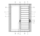
以下、本発明の実施の形態を図面に基づいて説明する。この建具は、種々の構成のものを含み、種々の用途に用いられるものであるが、ここでは玄関引戸の場合を例に挙げる。なお、以下において左右とは、図2に示すように、玄関引戸を室内側から見た際の左右方向を示す。図2は、この玄関引戸の室内側正面図であり、左右の縦枠2と、上枠6及び下枠7を四周枠組みした内周側に、二枚の障子1を引き違いに納めてある。障子1は、戸先框11と、召合框12と、上框13と、下框14を四周框組みした内周側にパネル体15を嵌め込んで構成したものである。なお、戸先框11の見付幅は、後述の取手3の見付幅よりも僅かに広いものとなっている。そして、右側の障子1の戸先框11の室内側面の上下方向中間部に、取手3を設けてある。また、右側の縦枠2の、取手3と略同じ高さ位置に、縦枠2と右側の障子1を施解錠して障子1の移動を規制する錠4を設けてあり、縦枠2の室内側面の上下方向中間部の、取手3と略同じ高さ位置に、錠4の操作部5を設けてある。さらに、二枚の障子1の召合框12の、取手3と略同じ高さ位置に、左右の障子1同士を施解錠して障子1の移動を規制する召合錠8を設けてあり、右側の障子1の召合框12の室内側面に、召合錠8の操作部81を設けてある。
Hereinafter, embodiments of the present invention will be described with reference to the drawings. This fitting includes those having various configurations and is used for various purposes, but here, the case of a front door sliding door will be taken as an example. In the following, as shown in FIG. 2, the left and right directions indicate the left and right directions when the entrance sliding door is viewed from the indoor side. FIG. 2 is a front view of the interior side of the entrance sliding door, and two
次に、取手3と縦枠2の錠4及び操作部5について詳述する。図1に示すように、取手3は、正面視して矩形の凹部31を有するものであり、平板に凹部31を形成したものを、凹部31を障子1の戸先框11の室内側面に形成した穴に嵌め込んで取り付けてある。よって、取手3の凹部31は障子1の戸先框11の室内側面に対して凹んだものとなり、取手3の凹部31に手指を掛けて、障子1を左右に摺動して開閉できる。
Next, the handle 3, the lock 4 of the
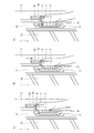
そして、縦枠2には、障子1を施解錠するための錠4と、この錠4の操作部5を有する操作体52を設けてある。錠4は、いわゆる鎌錠であって、縦枠2の内部に設けてあり、鎌形のデッドボルト41が縦枠2の戸当面から回転しながら突没するものである。障子1を閉鎖した状態で、錠4のデッドボルト41を突出させることで、デッドボルト41が障子1の戸先側面の受部(図示省略)に係合し、施錠される。また、操作体52は、縦枠2の室内側面に設けた上下に延びる角棒状の基部51と、基部51の上下方向中心から室内側に向けて突出しかつ左側(障子1側)に向けて延びる角棒状の操作部5からなる。基部51と操作部5は一体に形成されていて上下動可能であり、上下のどの位置にあっても、操作部5は常に取手3の凹部31の上下幅内に納まっていて、操作部5は、障子1側に向けて、取手3の室内側に近接している。具体的には、操作部5の左側(障子1側)の端部から、取手3の凹部31の左側の見込面(障子1を左側へ摺動させる際に指が掛かる面)までの距離(図1のD)が、45mmである。また、基部51と操作部5からなる操作体52を下側位置にしたときに、操作部5(操作体52)の上下方向中心の高さ位置が、取手3の上下方向中心の高さ位置と同じになる。これにより、少なくとも操作部5(操作体52)が下側位置にあるときに、一般的な体格の成人が操作部5に親指を載せた状態で、取手3の凹部31に他の指が掛かるものとなっている。なお、このように、操作部5に親指を載せた状態で、取手3の凹部31に他の指を掛けられるようにするためには、操作部5の左側(障子1側)の端部から、取手3の凹部31の左側の見込面までの距離(図1のD)が、35〜50mmであることが望ましい。そして、基部51が縦枠2の内部においてデッドボルト41と接続されており(接続機構は図示省略)、操作部5(操作体52)を動かして上側位置にすると(図1の実線)、錠4のデッドボルト41が縦枠2の戸当面から突出して施錠状態となり、下側位置にすると(図1の二点鎖線)、錠4のデッドボルト41が縦枠2の戸当面に没入して解錠状態となる。
The
次に、この操作部5及び取手3を操作して障子1を開ける場合の動作について説明する。当初、障子1が閉じられ、操作部5(操作体52)が上側位置にあって錠4により施錠された状態であるとする。この状態から障子1を開けるには、まず、図3(a)に示すように、右手の親指Tの腹を、操作部5に上側から当接させる。次に、図3(b)に示すように、操作部5に掛けた親指Tにより操作部5(操作体52)を押し下げて、錠4を解錠する。次に、図3(c)に示すように、操作部5に親指Tの腹を載せた状態で、取手3の凹部31に他の指Fを掛ける。そして、そのまま他の指Fで障子1を左側に摺動させて開く。
Next, the operation when the
また、このように右手のみで錠4の解錠操作と障子1の開操作を行うのではなく、両手で操作してもよい。その場合は、右手の何れかの指を操作部5に上側から当接させ、操作部5(操作体52)を押し下げて錠4を解錠し、左手の何れかの指を取手3の凹部31に掛けて、障子1を左側に摺動させて開く。
Further, instead of performing the unlocking operation of the lock 4 and the opening operation of the
このように構成した本発明の建具によれば、錠4の操作部5を障子1ではなく縦枠2に設けてあるので、障子1の戸先框11には取手3のみを設ければよく、戸先框11の見付幅を細くすることができる。そして、錠4の操作部5が、障子1側に向けて、取手3の室内側に近接しており、また少なくとも操作部5が下側位置にあるとき、すなわち錠4の解錠時に、一般的な体格の成人が操作部5に親指Tを載せた状態で、取手3の凹部31に他の指Fが掛かるものとなっているので、障子1を開く際、片手での操作、すなわち一方の手で錠4の操作部5を下げて解錠し、そのまま同じ手を取手3に掛けて障子1を開く操作が容易である。また、錠4の操作部5が、障子1側に向けて、取手3の室内側に近接しているので、障子1を開く際、両手での操作、すなわち一方の手で錠4の操作部5を下げて解錠し、他方の手を取手3に掛けて障子1を開く操作も容易である。
According to the fitting of the present invention configured in this way, since the
本発明は、上記の実施形態に限定されない。たとえば、本発明の建具は、玄関引戸以外の種々の用途にも用いられるものであり、障子は引き違いのほか、片引き、引き分けなどであってもよいし、テラスやガーデンルームなどに設けられる、複数枚のパネル体を伸縮自在に連結したルーバー引戸であってもよい。また、錠は、障子の移動を規制するものであればよく、障子と縦枠を直接連結して施錠するものに限られない。たとえば、障子が上記のルーバー引戸であって、障子と縦枠の間に、限られた範囲だけ障子の開閉方向に移動可能であって障子と結合・分離可能な可動枠を備え、可動枠を障子と結合させて移動させることで、ルーバー引戸がある程度開いて防犯性を確保しつつ通気が可能となり、可動枠を障子と分離させることで、障子が開閉自在となる建具において、縦枠と可動枠を連結して施錠するための錠であってもよい。この場合の錠は、障子(ルーバー引戸)と縦枠を直接連結して施錠するものではないが、可動枠を介して障子の移動を規制するものであり、これも本発明の建具の錠に相当し、この建具も本発明に含まれる。さらに、取手や操作部の形状は、指を掛けて操作することができるものであれば、どのようなものであってもよい。 The present invention is not limited to the above embodiments. For example, the fitting of the present invention is used for various purposes other than the entrance sliding door, and the shoji may be a louver, a louver, or the like, and is provided in a terrace, a garden room, or the like. , A louver sliding door in which a plurality of panel bodies are stretchably connected may be used. Further, the lock may be any one that regulates the movement of the shoji, and is not limited to the one that locks the shoji by directly connecting the vertical frame. For example, the shoji is the above-mentioned louver sliding door, and a movable frame is provided between the shoji and the vertical frame so that it can be moved in the opening and closing direction of the shoji within a limited range and can be combined with and separated from the shoji. By connecting with the shoji and moving it, the louver sliding door opens to some extent and ventilation is possible while ensuring crime prevention, and by separating the movable frame from the shoji, the vertical frame and movable are in the fittings that can open and close the shoji. It may be a lock for connecting and locking the frames. The lock in this case does not lock by directly connecting the shoji (louver sliding door) and the vertical frame, but regulates the movement of the shoji through the movable frame, which is also a lock for the fitting of the present invention. Correspondingly, this fitting is also included in the present invention. Further, the shape of the handle and the operation portion may be any shape as long as it can be operated by hanging a finger.
1 障子
2 縦枠
3 取手
4 錠
5 操作部
1
Claims (1)
Comprising a sash, a vertical frame, Yes and the handle provided on the door leading end side of the shoji, is provided with an operation portion of the lock for restricting the movement of the sash on the vertical frame, the operation unit slides move in the vertical direction It has been made to unlock the lock at the lower position, at least during unlocking, characterized in that in a state carrying the thumb on the operation unit, in which the other finger grip is applied joinery.
Priority Applications (1)
| Application Number | Priority Date | Filing Date | Title |
|---|---|---|---|
| JP2017109827A JP6851908B2 (en) | 2017-06-02 | 2017-06-02 | Joinery |
Applications Claiming Priority (1)
| Application Number | Priority Date | Filing Date | Title |
|---|---|---|---|
| JP2017109827A JP6851908B2 (en) | 2017-06-02 | 2017-06-02 | Joinery |
Publications (2)
| Publication Number | Publication Date |
|---|---|
| JP2018204275A JP2018204275A (en) | 2018-12-27 |
| JP6851908B2 true JP6851908B2 (en) | 2021-03-31 |
Family
ID=64956698
Family Applications (1)
| Application Number | Title | Priority Date | Filing Date |
|---|---|---|---|
| JP2017109827A Active JP6851908B2 (en) | 2017-06-02 | 2017-06-02 | Joinery |
Country Status (1)
| Country | Link |
|---|---|
| JP (1) | JP6851908B2 (en) |
Family Cites Families (6)
| Publication number | Priority date | Publication date | Assignee | Title |
|---|---|---|---|---|
| JPS5251673Y2 (en) * | 1973-09-03 | 1977-11-24 | ||
| US5653483A (en) * | 1993-09-29 | 1997-08-05 | Grover; Philip D. | Sliding door latch |
| JP4306414B2 (en) * | 2003-11-06 | 2009-08-05 | アイシン精機株式会社 | Sliding door locking device |
| JP4285334B2 (en) * | 2004-06-04 | 2009-06-24 | 三協立山アルミ株式会社 | sash |
| JP2007100369A (en) * | 2005-10-04 | 2007-04-19 | Misawa Homes Co Ltd | Sliding door |
| JP5158749B2 (en) * | 2007-03-14 | 2013-03-06 | 曙ブレーキ工業株式会社 | Window door opening and closing management system, security system and locking unit |
-
2017
- 2017-06-02 JP JP2017109827A patent/JP6851908B2/en active Active
Also Published As
| Publication number | Publication date |
|---|---|
| JP2018204275A (en) | 2018-12-27 |
Similar Documents
| Publication | Publication Date | Title |
|---|---|---|
| US9273486B2 (en) | Continuous handle for window | |
| US20170204644A1 (en) | Combination Door Assembly | |
| JP7422514B2 (en) | fittings | |
| JP6113765B2 (en) | Padlock | |
| US8083271B2 (en) | Window lock and sash | |
| JP6851908B2 (en) | Joinery | |
| JP5994054B2 (en) | Sliding door lock | |
| KR200439800Y1 (en) | Window handle | |
| KR101444911B1 (en) | A window for safe zone | |
| US9719287B1 (en) | Astragal with covered slidable lock block | |
| US826343A (en) | Sash-lock. | |
| JP2005256386A (en) | Sash | |
| CN104895470B (en) | There is ventilation and the operating assembly of locking device | |
| JP6251140B2 (en) | Locking device | |
| JP4082685B2 (en) | sash | |
| JP6433833B2 (en) | Locking device and joinery | |
| JP5728404B2 (en) | Joinery | |
| JP5986004B2 (en) | Joinery | |
| JP6995004B2 (en) | A window | |
| JP4433414B2 (en) | Single window | |
| KR100700151B1 (en) | Sliding door opener | |
| JP4234668B2 (en) | Double door | |
| KR101876832B1 (en) | Door handle for double windows | |
| KR20170067113A (en) | Locking device of sliding door | |
| JP3207069U (en) | Handle device with lock |
Legal Events
| Date | Code | Title | Description |
|---|---|---|---|
| A621 | Written request for application examination |
Free format text: JAPANESE INTERMEDIATE CODE: A621 Effective date: 20191225 |
|
| A977 | Report on retrieval |
Free format text: JAPANESE INTERMEDIATE CODE: A971007 Effective date: 20200916 |
|
| A131 | Notification of reasons for refusal |
Free format text: JAPANESE INTERMEDIATE CODE: A131 Effective date: 20200929 |
|
| A521 | Written amendment |
Free format text: JAPANESE INTERMEDIATE CODE: A523 Effective date: 20201118 |
|
| TRDD | Decision of grant or rejection written | ||
| A01 | Written decision to grant a patent or to grant a registration (utility model) |
Free format text: JAPANESE INTERMEDIATE CODE: A01 Effective date: 20210302 |
|
| A61 | First payment of annual fees (during grant procedure) |
Free format text: JAPANESE INTERMEDIATE CODE: A61 Effective date: 20210310 |
|
| R150 | Certificate of patent or registration of utility model |
Ref document number: 6851908 Country of ref document: JP Free format text: JAPANESE INTERMEDIATE CODE: R150 |