JP6849430B2 - Image processing equipment, image processing methods, and programs - Google Patents
Image processing equipment, image processing methods, and programs Download PDFInfo
- Publication number
- JP6849430B2 JP6849430B2 JP2016253276A JP2016253276A JP6849430B2 JP 6849430 B2 JP6849430 B2 JP 6849430B2 JP 2016253276 A JP2016253276 A JP 2016253276A JP 2016253276 A JP2016253276 A JP 2016253276A JP 6849430 B2 JP6849430 B2 JP 6849430B2
- Authority
- JP
- Japan
- Prior art keywords
- virtual viewpoint
- image
- virtual
- setting
- viewpoint
- Prior art date
- Legal status (The legal status is an assumption and is not a legal conclusion. Google has not performed a legal analysis and makes no representation as to the accuracy of the status listed.)
- Active
Links
- 238000003672 processing method Methods 0.000 title 1
- 238000000034 method Methods 0.000 claims description 28
- 230000003287 optical effect Effects 0.000 claims description 19
- 238000010586 diagram Methods 0.000 description 17
- 238000009795 derivation Methods 0.000 description 13
- 239000013598 vector Substances 0.000 description 7
- 239000000203 mixture Substances 0.000 description 5
- 238000013459 approach Methods 0.000 description 3
- 230000006870 function Effects 0.000 description 3
- 240000004050 Pentaglottis sempervirens Species 0.000 description 1
- 235000004522 Pentaglottis sempervirens Nutrition 0.000 description 1
- 230000015572 biosynthetic process Effects 0.000 description 1
- 239000002131 composite material Substances 0.000 description 1
- 230000001419 dependent effect Effects 0.000 description 1
- 238000000605 extraction Methods 0.000 description 1
- 238000003384 imaging method Methods 0.000 description 1
- 238000002347 injection Methods 0.000 description 1
- 239000007924 injection Substances 0.000 description 1
- 239000004973 liquid crystal related substance Substances 0.000 description 1
- 238000013507 mapping Methods 0.000 description 1
- 230000036544 posture Effects 0.000 description 1
- 238000009877 rendering Methods 0.000 description 1
- 230000035807 sensation Effects 0.000 description 1
- 239000000243 solution Substances 0.000 description 1
- 230000002194 synthesizing effect Effects 0.000 description 1
Images


Classifications
-
- H—ELECTRICITY
- H04—ELECTRIC COMMUNICATION TECHNIQUE
- H04N—PICTORIAL COMMUNICATION, e.g. TELEVISION
- H04N13/00—Stereoscopic video systems; Multi-view video systems; Details thereof
- H04N13/20—Image signal generators
- H04N13/282—Image signal generators for generating image signals corresponding to three or more geometrical viewpoints, e.g. multi-view systems
-
- G—PHYSICS
- G06—COMPUTING; CALCULATING OR COUNTING
- G06T—IMAGE DATA PROCESSING OR GENERATION, IN GENERAL
- G06T15/00—3D [Three Dimensional] image rendering
- G06T15/10—Geometric effects
- G06T15/20—Perspective computation
- G06T15/205—Image-based rendering
-
- G—PHYSICS
- G06—COMPUTING; CALCULATING OR COUNTING
- G06T—IMAGE DATA PROCESSING OR GENERATION, IN GENERAL
- G06T19/00—Manipulating 3D models or images for computer graphics
- G06T19/003—Navigation within 3D models or images
-
- G—PHYSICS
- G06—COMPUTING; CALCULATING OR COUNTING
- G06T—IMAGE DATA PROCESSING OR GENERATION, IN GENERAL
- G06T7/00—Image analysis
- G06T7/20—Analysis of motion
- G06T7/246—Analysis of motion using feature-based methods, e.g. the tracking of corners or segments
- G06T7/248—Analysis of motion using feature-based methods, e.g. the tracking of corners or segments involving reference images or patches
-
- G—PHYSICS
- G06—COMPUTING; CALCULATING OR COUNTING
- G06T—IMAGE DATA PROCESSING OR GENERATION, IN GENERAL
- G06T7/00—Image analysis
- G06T7/20—Analysis of motion
- G06T7/292—Multi-camera tracking
-
- G—PHYSICS
- G06—COMPUTING; CALCULATING OR COUNTING
- G06T—IMAGE DATA PROCESSING OR GENERATION, IN GENERAL
- G06T7/00—Image analysis
- G06T7/70—Determining position or orientation of objects or cameras
- G06T7/73—Determining position or orientation of objects or cameras using feature-based methods
-
- G—PHYSICS
- G06—COMPUTING; CALCULATING OR COUNTING
- G06T—IMAGE DATA PROCESSING OR GENERATION, IN GENERAL
- G06T15/00—3D [Three Dimensional] image rendering
- G06T15/04—Texture mapping
Description
本発明は、異なる視点から撮影された多視点映像を用いた、自由視点映像生成技術に関する。 The present invention relates to a free-viewpoint image generation technique using multi-viewpoint images taken from different viewpoints.
複数台の実カメラで撮影した多視点の映像を用いて、3次元空間内に仮想的に配置した実際には存在しないカメラ(仮想カメラ)からの映像を再現する技術として、自由視点映像技術がある。自由視点映像の生成手法の一つに、被写体を囲むように撮影して得られた多視点映像から被写体の3次元形状を推定し、求めた3次元形状の表面に撮影画像をテクスチャマッピングすることにより、自由視点映像を得る手法がある。このとき、生成したい自由視点の位置によって、どの視点の撮影画像をテクスチャマッピングに用いるかが、自由視点映像の画質に大きな影響を与える。この点、特許文献1には、生成したい自由視点の光軸方向と撮影視点の光軸方向に基づいて画像合成時のブレンド率を算出し、撮影視点の光軸方向が自由視点のそれに近い撮影画像の合成時の重みを高くすることで、高画質を実現する技術が開示されている。 Free-viewpoint video technology is a technology that reproduces images from cameras (virtual cameras) that do not actually exist and are virtually placed in a three-dimensional space using multi-viewpoint images taken by multiple real cameras. is there. One of the methods for generating a free-viewpoint image is to estimate the three-dimensional shape of the subject from the multi-viewpoint image obtained by shooting so as to surround the subject, and texture-map the shot image to the surface of the obtained three-dimensional shape. There is a method of obtaining a free-viewpoint image. At this time, depending on the position of the free viewpoint to be generated, which viewpoint's captured image is used for texture mapping has a great influence on the image quality of the free viewpoint image. In this regard, in Patent Document 1, the blend ratio at the time of image composition is calculated based on the optical axis direction of the free viewpoint to be generated and the optical axis direction of the shooting viewpoint, and the optical axis direction of the shooting viewpoint is close to that of the free viewpoint. A technique for achieving high image quality by increasing the weight at the time of image composition is disclosed.
上記特許文献1の手法では、多視点映像における撮影画像間で被写体領域におけるボケ量が異なる場合、出来上がった自由視点映像においてボケ量のバラつきが生じてしまう。具体的には、自由視点映像の対象被写体に合焦している撮影画像と、当該対象被写体に合焦していない撮影画像とが混在する場合、前者をテクスチャマッピングしたフレームと後者をテクスチャマッピングしたフレームとの間で、ボケ量に差が生じることになる。そのような自由視点映像は、視る者に違和感を与えてしまうことになり望ましくない。 In the method of Patent Document 1, when the amount of blur in the subject area differs between the captured images in the multi-viewpoint image, the amount of blurring occurs in the completed free-viewpoint image. Specifically, when the captured image focused on the target subject of the free-viewpoint image and the captured image not focused on the target subject are mixed, the frame in which the former is texture-mapped and the frame in which the latter is texture-mapped are texture-mapped. There will be a difference in the amount of blur between the frame and the frame. Such a free-viewpoint image is not desirable because it gives the viewer a sense of discomfort.
本発明では、多視点映像に含まれる撮影画像間で被写体領域におけるボケが異なる場合でも、視る者に違和感を与えない自由視点映像を生成することを目的とする。 An object of the present invention is to generate a free-viewpoint image that does not give a sense of discomfort to the viewer even when the blurred image in the subject area differs between the captured images included in the multi-viewpoint image.
本発明に係る設定装置は、複数の撮影装置により撮影領域をそれぞれ異なる方向から撮影することで得られる画像データに基づいて仮想視点に対応する仮想視点画像を生成するための、前記仮想視点の移動経路を設定する設定装置であって、前記撮影領域内のオブジェクトを指定する指定手段と、前記指定手段による前記オブジェクトの指定と前記仮想視点の移動に係る所定の基準とに応じた前記仮想視点の移動経路を設定する設定手段であって、前記仮想視点の移動に伴う前記仮想視点画像における前記オブジェクトの画質の変化が抑えられるように、前記仮想視点の位置と前記仮想視点画像における前記オブジェクトの画質との関係に基づいて前記仮想視点の移動経路を設定する設定手段と、を有することを特徴とする。 The setting device according to the present invention moves the virtual viewpoint in order to generate a virtual viewpoint image corresponding to the virtual viewpoint based on image data obtained by shooting a shooting area from different directions by a plurality of shooting devices. A setting device for setting a route, in which a designation means for designating an object in the shooting area, a designation of the object by the designation means, and a predetermined reference for moving the virtual viewpoint of the virtual viewpoint. It is a setting means for setting a movement path, and the position of the virtual viewpoint and the image quality of the object in the virtual viewpoint image are suppressed so that the change in the image quality of the object in the virtual viewpoint image due to the movement of the virtual viewpoint is suppressed. It is characterized by having a setting means for setting a movement path of the virtual viewpoint based on the relationship with the above.
本発明によれば、多視点映像に含まれる撮影画像間で被写体領域におけるボケが異なる場合でも、視る者に違和感を与えない自由視点映像を生成することが可能である。 According to the present invention, it is possible to generate a free-viewpoint image that does not give a sense of discomfort to the viewer even when the blurred image in the subject area differs between the captured images included in the multi-viewpoint image.
以下、添付図面を参照して、本発明を好適な実施例に従って詳細に説明する。なお、以下の実施例において示す構成は一例にすぎず、本発明は図示された構成に限定されるものではない。 Hereinafter, the present invention will be described in detail with reference to the accompanying drawings according to preferred embodiments. The configuration shown in the following examples is only an example, and the present invention is not limited to the illustrated configuration.
図1は、画像処理装置100のハードウェア構成の一例を示す図である。画像処理装置100は、CPU101、RAM102、ROM103、HDD104、入出力I/F105で構成される。そして、画像処理装置100を構成する各部は、システムバス106によって相互に接続されている。また、画像処理装置100は、入出力I/F105を介して、カメラ201〜210、表示操作部110、外部メモリ111に接続されている。
FIG. 1 is a diagram showing an example of a hardware configuration of the
CPU101は、RAM102をワークメモリとして、ROM103に格納されたプログラムを実行し、システムバス106を介して画像処理装置100の各部を統括的に制御する。これにより、後述する様々な処理が実現される。HDD104は、画像処理装置100で取り扱う種々のデータを記憶する大容量記憶装置であり、例えばSSDなどでもよい。CPU101は、システムバス106を介してHDD104へのデータの書き込み及びHDD104に記憶されたデータの読出しを行うことができる。
The
入出力I/F105は、例えばUSBやIEEE1394等のシリアルバスI/Fであり、外部装置と画像処理装置100との間の各種データ・命令等の入力や出力が、この入出力I/F105を介して行われる。外部メモリ111は、例えば、ハードディスク、メモリーカード、CFカード、SDカード、USBメモリなどの記憶媒体である。表示操作部110は、例えばタッチパネル機能を有する液晶ディスプレイなどで構成され、ユーザに対する必要な情報の表示や、UI画面を介してユーザからの指示を取得する。なお、画像処理装置100の構成要素は上記以外にも存在するが、本発明の主眼ではないため、説明を省略する。
The input / output I /
図2は、異なる複数の視点から撮影して互いに視差のある多視点映像を取得するためのカメラ配置の一例を示した図である。図2は、被撮影領域としてのフィールド220を囲むように配置された10台のカメラ201〜210により、フィールド220上にいる選手221、222及びボール223を撮影している様子を表している。図2(a)は横から見た場合のカメラ配置、図2(b)は俯瞰で見た場合のカメラ配置である。本実施例では、×印224が全てのカメラ201〜210の注視点となるように配置されている。ここで注視点とは、カメラ201〜210それぞれの光軸上にあり、かつ合焦している点を指す。カメラ201〜210はどれも焦点距離が同じレンズを有しており、それぞれが有する撮像素子の画素数も等しいものとする。なお、撮影に用いるカメラの数や構成、配置は上記の例に限定されるものではない。また、各カメラの注視点や焦点距離、撮像素子の画素数が互いに異なっていてもよい。また、本実施例では、各撮影視点に対応した複数のカメラによって多視点映像の撮影を行うものとしているが、1つあるいは複数のカメラが視点を変えながら複数回撮影することで多視点映像を取得してもよい。
FIG. 2 is a diagram showing an example of a camera arrangement for acquiring multi-viewpoint images having parallax with each other by shooting from a plurality of different viewpoints. FIG. 2 shows a state in which the
座標系225はカメラの位置などを特定するときに用いる座標系を示している。xy平面上の矩形領域である被撮影領域としてのフィールド220が、本実施例において画像処理の対象となる範囲となる。カメラ201〜210による撮影画像データは、多視点映像データとして画像処理装置100に送られ、所定の画像処理が施される。
The coordinate
続いて、画像処理装置100で行う自由視点映像の生成処理について説明する。図3は、本実施例に係る画像処理装置100の機能ブロック図である。画像処理装置100は、仮想注視点設定部301、仮想視点設定部302、撮影パラメータ取得部303、ボケ量導出部304、生成条件設定部305、限界焦点距離導出部306、カメラワーク設定部307、多視点映像取得部308、自由視点映像生成部309で構成される。以下、各部について説明する。
Subsequently, the free viewpoint image generation process performed by the
仮想注視点設定部301は、自由視点映像の仮想カメラが注視する点(仮想注視点)の位置を設定する。この位置は座標系225に従う。生成される自由視点映像の対象タイムフレーム内で仮想注視点が変移する場合は、その変移する位置の軌跡が設定されることになる。この設定は、表示操作部110に表示されるUI画面を介したユーザ入力に基づいて行なわれる。或いは、事前に決定・保持しておいた位置座標の情報をHDD104等から取得してもよい。
The virtual gazing
仮想視点設定部302は、自由視点映像生成時の各フレームにおける仮想カメラの位置(仮想視点)を設定する。この設定も、表示操作部110に表示されるUI画面を介したユーザ入力に基づいて行なわれる。或いは、仮想注視点設定部301で設定された仮想注視点の位置情報に基づいて計算で求めてもよい。例えば、仮想注視点となる対象被写体が対象タイムフレームの全範囲において位置(xd,yd,zd)で固定であって、当該対象被写体の周りを360度1周する自由視点映像を生成する場合の、円形の軌跡を描く仮想視点は、以下の式(1)で表される。
The virtual

上記式(1)において、mはフレーム番号、Vm(x,y,z)は各フレームにおける仮想カメラの視点位置、rは円の半径、θmは各フレームにおける仮想視点の方向をそれぞれ表している。 In the above equation (1), m is the frame number, Vm (x, y, z) is the viewpoint position of the virtual camera in each frame, r is the radius of the circle, and θm is the direction of the virtual viewpoint in each frame. ..
撮影パラメータ取得部303は、カメラ201〜210の撮影パラメータを取得する。以下に撮影パラメータの代表的なものを挙げる。
The shooting
・カメラ201〜210それぞれの位置(x201,y201,z201)〜(x210,y210,z210)
・カメラ201〜210それぞれの姿勢(α201,β201,γ201)〜(α210,β210,γ210)
・カメラ201〜210の注視点の位置(xl,yl,zl)
・レンズの焦点距離f201〜f210
・レンズの主点位置(cx201,cy201)〜(cx210,cy210)
・カメラ201〜210のF値(F201)〜(F210)
・撮像素子のサイズ(w201,h201)〜(w210,h210)
・撮像素子の解像度(Rcx201, Rcy201)〜(Rcx210, Rcy210)
これら撮影パラメータを、予めHDD104に保持しておく、或いは、公知のzhangの手法(非特許文献1を参照)などを用いたカメラキャリブレーションを行って取得する。
-Camera 201-210 positions (x201, y201, z201) to (x210, y210, z210)
-Camera 2011-210 postures (α201, β201, γ201) to (α210, β210, γ210)
-Position of the gazing point of cameras 2001-210 (xl, yl, zl)
・ Lens focal lengths f201 to f210
・ Lens principal point position (cx201, cy201) ~ (cx210, cy210)
-F values (F201) to (F210) of cameras 201-210
-Image sensor size (w201, h201) to (w210, h210)
-Image sensor resolution (Rcx201, Rcy201) to (Rcx210, Rcy210)
These imaging parameters are stored in the
ボケ量導出部304は、仮想注視点設定部301で設定された仮想注視点及び撮影パラメータ取得部303が取得した撮影パラメータに基づいて、カメラ201〜210で撮影された多視点映像の仮想注視点におけるボケ量を導出する。ここで、ボケ量は、極小の点像を撮影したときにその点像が撮像素子(センサ)上で何画素になるかを数値で表したものである。ボケ量(Bxn,Byn)は以下の式(2)によって求めることができる。
The blur
上記式(2)において、Bxnはカメラnが撮影した画像における被写体の横方向のボケ量、Bynは縦方向のボケ量を表している。Lnは、カメラnの位置から合焦位置までのベクトルであり、以下の式(3)で表される。Dnは、カメラnの位置から仮想注視点位置までのベクトルであり、以下の式(4)で表される。(Pxn,Pyn)は、撮像素子上での1画素の大きさを表し、以下の式(5)で表される。 In the above equation (2), Bx n represents the amount of blur in the horizontal direction of the subject in the image taken by the camera n, and By n represents the amount of blur in the vertical direction. L n is a vector from the position of the camera n to the in-focus position, and is expressed by the following equation (3). D n is a vector from the position of the camera n to the virtual gazing point position, and is expressed by the following equation (4). (Px n , Py n ) represents the size of one pixel on the image sensor, and is represented by the following equation (5).
生成条件設定部305は、生成する自由視点映像の生成条件、具体的には、出力解像度Rd、許容されるボケ量(ボケ量許容値)b´、入力多視点映像のうちの対象タイムフレームなどを設定する。出力解像度Rd、ボケ量許容値b´及び対象タイムフレームは、表示操作部110を介してユーザによって入力される。
The generation
限界焦点距離導出部306は、設定された仮想視点の経路上の各位置においてズーム可能な範囲(限界焦点距離)を導出する。この限界焦点距離は以下のように導出される。まず、仮想視点の位置座標、被写体の位置座標、仮想注視点の位置座標及び撮影パラメータに基づいて、仮想視点の経路上の注目する位置(以下、注目仮想視点位置)からみた画像の生成に用いる参照画像が決定される。具体的には、以下の式(6)により仮想視点位置の光軸ベクトルCを算出し、算出した光軸ベクトルCと全てのカメラの光軸ベクトルLnの内積Eを以下の式(7)により求めて、内積Eが最大となるカメラnの撮影画像を、参照画像として選択する。
The limit focal
![]()
![]()
その後、選択された撮影画像に対応するカメラnの撮影パラメータと被写体近傍におけるボケ量、生成条件設定部305で設定された出力解像度及びボケ量許容値に基づいて、仮想視点位置でズーム可能な焦点距離の限界値f´が、以下の式(8)により求められる。
After that, the focal length that can be zoomed at the virtual viewpoint position is based on the shooting parameters of the camera n corresponding to the selected shot image, the amount of blur in the vicinity of the subject, the output resolution set by the generation
上記式(8)において、bは参照画像の被写体近傍におけるボケ量、dは参照画像を撮影したカメラnから仮想注視点までの距離、fは参照画像撮影時の焦点距離、b´はボケ量許容値、d´は仮想視点位置から仮想注視点までの距離、Rcはカメラnの解像度、Rdは出力解像度を示している。また、 In the above equation (8), b is the amount of blur in the vicinity of the subject of the reference image, d is the distance from the camera n that captured the reference image to the virtual gazing point, f is the focal length at the time of capturing the reference image, and b'is the amount of blur. The permissible value, d'is the distance from the virtual viewpoint position to the virtual gazing point, Rc is the resolution of the camera n, and Rd is the output resolution. Also,
は参照画像の光軸Lと仮想視点位置の光軸Cが交差する角度のコサインを示している。ここで、仮想カメラのセンササイズは選択された撮影画像に対応するカメラnのセンササイズと同一であるものとする。また、仮想視点位置からみた画像(仮想視点画像)は無限の被写界深度を持ち、被写体に合焦していないことによる画像のボケは発生しない。従って、上記式(8)では入力撮影画像のボケ量が仮想視点画像に与える影響のみを考慮している。仮想視点位置の焦点距離が、算出された限界焦点距離f´より小さい場合、生成される仮想視点画像のボケ量がボケ量許容値以下となり、良好な画像を生成することができる。 Shows the cosine of the angle at which the optical axis L of the reference image and the optical axis C of the virtual viewpoint position intersect. Here, it is assumed that the sensor size of the virtual camera is the same as the sensor size of the camera n corresponding to the selected captured image. Further, the image viewed from the virtual viewpoint position (virtual viewpoint image) has an infinite depth of field, and the image is not blurred due to not being in focus on the subject. Therefore, in the above equation (8), only the influence of the amount of blurring of the input captured image on the virtual viewpoint image is considered. When the focal length of the virtual viewpoint position is smaller than the calculated limit focal length f', the amount of blurring of the generated virtual viewpoint image is equal to or less than the allowable amount of blurring, and a good image can be generated.
なお、本実施例では、設定された仮想視点に基づき、当該仮想視点の経路上の各位置から仮想注視点までの距離d´を固定値として上記式(8)に代入することにより限界焦点距離f´を求めている。しかしながら、事前に仮想視点の焦点距離を決定しておき、接近可能な仮想視点の限界距離d´を求めてもよい。或いは、焦点距離と、仮想視点位置から仮想注視点までの距離との適切な組み合わせを得るために、f´/d´の値を求めてもよい。また、本実施例では、単一の参照画像を選択しているが、選択する参照画像は複数であってもよい。例えば、内積Eの値に基づいて各撮影画像の重みを求め、複数のカメラの撮影画像を参照画像として選択した上で、後述する自由視点映像生成部309で選択した複数の参照画像を用いて画像合成を行う構成であってもよい。この場合の限界焦点距離としては、選択された各撮影画像に基づき求めた複数の限界焦点距離のうち最小の値、或いは当該複数の限界焦点距離に重み付け加算を行った値などを用いればよい。
In this embodiment, based on the set virtual viewpoint, the limit focal length is substituted into the above equation (8) by substituting the distance d'from each position on the path of the virtual viewpoint to the virtual gazing point as a fixed value. I'm looking for f'. However, the focal length of the virtual viewpoint may be determined in advance, and the limit distance d'of the virtual viewpoint that can be approached may be obtained. Alternatively, the value of f'/ d'may be obtained in order to obtain an appropriate combination of the focal length and the distance from the virtual viewpoint position to the virtual gazing point. Further, in this embodiment, a single reference image is selected, but a plurality of reference images may be selected. For example, the weight of each captured image is obtained based on the value of the inner product E, the captured images of a plurality of cameras are selected as reference images, and then a plurality of reference images selected by the free viewpoint
カメラワーク設定部307は、自由視点映像生成時のカメラワークを設定する。ここでカメラワークとは、対象タイムフレームにおける自由視点映像の生成に必要な仮想視点、仮想注視点、仮想カメラの焦点距離などのパラメータの集合を意味する。本実施例では、仮想視点設定部302で設定した仮想視点において、限界焦点距離導出部306で導出した限界焦点距離を超えない範囲で焦点距離がスムーズに変移するよう、各仮想視点位置における仮想視点画像生成時の焦点距離が設定される。
The camera
多視点映像取得部308は、カメラ201〜210がそれぞれ取得した撮影画像の集合である多視点映像データを取得する。取得した多視点映像データは、自由視点映像生成部309に入力される。
The multi-viewpoint
自由視点映像生成部309は、カメラワーク設定部307で設定されたカメラワークと、多視点映像取得部308から入力された多視点映像データに基づいて、各仮想視点位置の仮想視点画像を生成し、これを繋ぎ合わせることにより自由視点映像を生成する。自由視点映像の生成には非特許文献2に記載されているView dependent renderingなどが使用可能である。
The free viewpoint
上述のような構成の画像処理装置100における自由視点映像生成処理の具体的な流れを説明する前に、本発明の解決課題について、ここで改めて確認しておく。図4(a)は、図2で示したカメラ配置における一部のカメラの光軸を示した図である。図4(a)において、矢印線401はカメラ207、矢印線402はカメラ204の光軸を示している。
Before explaining the specific flow of the free-viewpoint image generation process in the
まず、仮想注視点が被写体221の位置(=実注視点224の近傍)にある場合について説明する。図4(b)は、被写体221の周囲を反時計回りに1周する仮想視点の経路を矢印線403で示した図である。図4(b)において矢印線403上の破線で示す3台のカメラ404〜406は、仮想視点の経路上にある任意の位置を示している。ここで、カメラ207の撮影画像の被写体近傍におけるボケ量(Bx207,By207)を前述の式(5)を用いて求めるとする。この場合、光軸401上でのカメラ207から実注視点224までの距離とカメラ207から被写体までの距離との差を示す。
First, a case where the virtual gazing point is at the position of the subject 221 (= near the actual gazing point 224) will be described. FIG. 4B is a diagram showing the path of the virtual viewpoint that makes one round counterclockwise around the subject 221 by the
の値が小さいので、ボケ量Bx207及びBy207は共に小さな値になる。同様に、カメラ204を含む他のカメラについてボケ量(Bxn,Byn)を求めた場合も、各撮影画像のボケ量は小さくなる。これらの撮影画像を用いて自由視点映像を生成した場合、入力撮影画像の被写体近傍におけるボケ量に大きな差がないため、仮想カメラ404、405、406の各仮想視点位置において生成された仮想視点画像のボケ量にも大きな差は生じない。このような場合には、仮想視点経路上のどの位置においてもボケ量のばらつきが小さい自由視点映像を生成することができる。
Since the value of is small, both the bokeh amount Bx 207 and By 207 are small values. Similarly, when the amount of blur (B x n , By n ) is obtained for other cameras including the
次に、仮想注視点が被写体222の位置(=実注視点224からやや離れた位置)にある場合について説明する。図5(a)は、被写体222の周囲を反時計回りに1周する仮想視点の経路を矢印線501で示した図である。図5(a)において矢印線501上の破線で示す3台のカメラ502〜504は、仮想視点の経路上にある任意の仮想カメラ位置を示している。また、図5(b)は、図4(a)に対応する図であり、両矢印線511はカメラ204の光軸402上での被写体222と実注視点224との距離、両矢印線512はカメラ207の光軸402上での被写体222と実注視点224との距離を示している。この場合、カメラ204については光軸402上での被写体222と実注視点224との距離が離れているため、被写体近傍のボケ量(Bx204,By204)は大きな値になる。一方、カメラ207については光軸401上での被写体222と実注視点224との距離が近いため、被写体近傍のボケ量(Bx207,By207)は小さな値になる。また、その他のカメラについても、各光軸上での被写体222と実注視点224との距離に応じて、被写体近傍のボケ量(Bxn,Byn)の値が小さいものと大きいものとが混在する。これらの撮影画像を用いて自由視点映像を生成した場合、仮想視点経路上の各位置における仮想視点画像を同一の焦点距離で生成すると、各位置で生成した仮想視点画像のボケ量に大きな差が生じることになる。図6は、被写体222について仮想視点経路上の位置502、503、504のそれぞれから共通の焦点距離で生成した仮想視点画像のボケ具合を示す図である。位置503で生成した仮想視点画像はカメラ204の撮像画像を使用するため大きくボケた画像となり、位置502及び504で生成した仮想視点画像はそれぞれカメラ201とカメラ207の撮像画像を使用するためボケの小さい画像となる。このようにボケの程度にばらつきのある仮想視点画像を繋ぎ合わせて自由視点映像を生成した場合、視聴者にとって違和感のある映像となってしまう。これが本発明の解決課題である。
Next, a case where the virtual gazing point is at the position of the subject 222 (= a position slightly distant from the actual gazing point 224) will be described. FIG. 5A is a diagram showing a path of a virtual viewpoint that goes around the subject 222 in a counterclockwise direction by an
以上を踏まえ、本実施例に係る自由視点映像生成処理の流れを詳しく説明する。図7は、本実施例に係る自由視点映像生成処理の流れを示すフローチャートである。以下に示す一連の処理は、CPU101が、HDD104等に格納されている所定のプログラムをRAM102にロードし、実行することで実現される。
Based on the above, the flow of the free-viewpoint video generation process according to this embodiment will be described in detail. FIG. 7 is a flowchart showing the flow of the free viewpoint video generation process according to the present embodiment. The series of processes shown below is realized by the
ステッ701では、撮影パラメータ取得部303においてカメラ201〜210の撮影パラメータが、多視点映像取得部308においてカメラ201〜210で撮影された多視点映像データがそれぞれ取得される。
In step 701, the shooting
ステップ702では、自由視点映像を生成するために必要な基礎情報がユーザ入力に基づき設定される。具体的には、仮想注視点設定部301では仮想注視点、仮想視点設定部302では仮想視点、生成条件設定部305では、生成する自由視点映像の出力解像度、ボケ量許容値、対象タイムフレームなどが設定される。
In step 702, the basic information necessary for generating the free viewpoint video is set based on the user input. Specifically, the virtual gaze
ステップ703では、ボケ量導出部304が、ステップ701で取得された多視点映像について、ステップ702で設定された仮想注視点におけるボケ量を導出する。ここで、具体的なボケ量の導出例を前述の図5の場合を例に説明する。いま、カメラ201〜210の注視点を×印224の位置 (x,y,z)=(0,0,1000)、仮想カメラ502〜504の仮想注視点を被写体222の位置(xd,yd,zd)=(40000,-5000,1000)とする。この場合の仮想カメラの位置Vmは前述の式(1)で求まり、例えばr=10000、θm=0度とすると、仮想カメラ503の位置Vm=(50000,-5000,1000)となる。そして、ボケ量(Bxn,Byn)は前述の式(2)によって求まり、例えばカメラ203と204については以下のようになる。いま、カメラ203が位置(45000,80000,1000)、カメラ204が位置(90000,15000,1000)にあるとする。この場合、カメラ203及び204の位置から、実際の注視点位置までのベクトルL203及びL204と仮想の注視点位置までのベクトルD203及びD204はそれぞれ、
In step 703, the blur
となる。そして、撮像素子上での1画素の大きさ(Pxn,Pyn)=(5μm,5μm)とし、焦点距離f=100mm、F値=4とすると、カメラ203及び204で撮像した画像における横方向のボケ量Bx203及びBx204はそれぞれ、
Bx203=45.76/8.45=5.41pix
Bx204=63.29/5.1003=12.41pix
となる。このようにして、縦方向のボケ量By203及びBy204についても、また他のカメラの撮影画像についても、同様に、仮想注視点位置(xd,yd,zd)=(40000,-5000,1000)におけるボケ量が求められることになる。
Will be. Then, assuming that the size of one pixel on the image sensor (Px n, Py n ) = (5 μm, 5 μm), the focal length f = 100 mm, and the F value = 4, the horizontal in the images captured by the
Bx 203 = 45.76 / 8.45 = 5.41pix
Bx 204 = 63.29 / 5.1003 = 12.41pix
Will be. In this way, the virtual gaze position (xd, yd, zd) = (40000, -5000, 1000) for the vertical blur amounts By 203 and By 204, as well as for the images taken by other cameras. ) Will be required.
ステップ704では、限界焦点距離導出部306において、ステップ702で設定された仮想視点の経路上における注目する位置(以下、仮想視点位置)における限界焦点距離が前述の式(8)を用いて求められる。例えば、仮想視点位置と仮想注視点とが図5のような位置関係にある場合には、選択された参照画像における位置(xd,yd,zd)=(40000,-5000,1000)のボケ量をbとして、前述の式(8)に代入すればよい。この例の場合、カメラ203の近くの仮想視点画像を生成するときよりも、カメラ204の近くの仮想視点画像を生成するときの方が、限界焦点距離は短くなる(すなわち、ズーム可能な範囲が狭く、より広角になる)。
In step 704, in the limit focal
ステップ705では、ステップ702で設定された仮想視点の経路上のすべての位置について(=設定された対象タイムフレームの全範囲について)、限界焦点距離の導出が終了したかどうかが判定される。仮想視点経路上のすべての位置についての処理が完了していれば、ステップ707に進む。一方、未処理の仮想視点位置があればステップ706に進み、仮想視点位置が更新されてステップ704の処理が繰り返される。 In step 705, it is determined whether or not the derivation of the limit focal length is completed for all the positions on the path of the virtual viewpoint set in step 702 (= for the entire range of the set target time frame). If the processing for all the positions on the virtual viewpoint path is completed, the process proceeds to step 707. On the other hand, if there is an unprocessed virtual viewpoint position, the process proceeds to step 706, the virtual viewpoint position is updated, and the process of step 704 is repeated.
ステップ707では、カメラワーク設定部307において、ステップ702で設定された仮想視点とステップ705で導出された各仮想視点位置における限界焦点距離とに基づいて、対象タイムフレームにおける自由視点映像のカメラワークを設定する。この際、カメラワークの設定基準を予め定めておき、その設定基準に従ったカメラワークに自動で決定される。設定基準としては、例えば各仮想視点画像の焦点距離を、各仮想視点位置の限界焦点距離における限界値にする、或いは全仮想視点位置の全限界焦点距離の中から最も焦点距離が短いものにする、といったことが考えられる。
In
ステップ708では、自由視点映像生成部309において、ステップ707で決定されたカメラワークとステップ701で取得した多視点映像データに基づいて、自由視点映像が生成される。なお、設定された対象タイムフレームが例えば10secで、多視点映像データが60fpsで撮影されている場合には、60(fps)×10(sec)=600フレーム分について、上記の処理がなされることになる。また、対象タイムフレーム内で仮想視点に加え仮想注視点も変移する場合には、ステップ706において仮想注視点の更新も行った上でステップ703まで戻り、ボケ量の導出から繰り返し行なうようにすればよい。
In step 708, the free-viewpoint
以上が、本実施例に係る自由視点映像生成処理の内容である。図8の(a)及び(b)は、いずれも本実施例を適用して得られる仮想視点画像の一例を示している。図8(a)の例では、参照画像のボケ量が小さく限界焦点距離の長い仮想視点位置(仮想カメラ502及び504)については焦点距離を大きく取り、被写体222を相対的に大きく映した仮想視点画像を生成している。また、参照画像のボケ量が大きく限界焦点距離の短い仮想視点位置(仮想カメラ503)については焦点距離を小さく取り、被写体222を相対的に小さく映した仮想視点画像を生成し、ボケ量が許容範囲内となるようにしている。このように実際の注視点と仮想注視点との位置関係に基づいて各参照画像の焦点距離を調節したカメラワークとすることで、自由視点映像内で許容値を超えたボケが発生することを抑制できる。また、図8(b)の例では、各仮想視点位置における焦点距離を限界焦点距離の短い仮想視点位置(仮想カメラ503)に合わせて小さく取り、どの仮想視点画像においても被写体222を小さく映している。このようなカメラワークとすることで、すべての仮想視点画像においてボケ量が許容値を超えることを防ぎつつ、これらを繋ぎ合せて生成される自由視点映像において被写体の大きさが大きく変動することによる違和感も抑制することができる。図8(a)と(b)のいずれの場合も、各仮想視点位置について、限界焦点距離より小さい焦点距離を用いて仮想視点画像が生成されるため、出来上がった自由視点映像においてはユーザに違和感を与えるようなボケの発生が抑制される。
The above is the content of the free-viewpoint video generation process according to this embodiment. Both (a) and (b) of FIG. 8 show an example of a virtual viewpoint image obtained by applying this embodiment. In the example of FIG. 8A, the focal length is set large for the virtual viewpoint positions (
なお、上述の例では、多視点映像データを処理の前段で取得していたが、例えばカメラワークの決定後にタイムフレーム分の多視点映像データを取得する構成でもよい。このように処理の後段で多視点映像データを取得する場合、例えば考えられる全ての被写体位置(仮想注視点位置)のケースについて予めカメラワークを求めておいてもよい。そして、自由視点映像生成時にユーザが指定した被写体位置について、予め求めておいたカメラワークの中から該当するものを用いて自由視点映像を生成するように構成することも可能である。 In the above example, the multi-viewpoint video data was acquired before the processing, but for example, the multi-viewpoint video data for the time frame may be acquired after the camera work is determined. When acquiring multi-viewpoint video data in the subsequent stage of processing in this way, for example, camera work may be obtained in advance for cases of all possible subject positions (virtual gazing point positions). Then, it is also possible to configure the subject position specified by the user at the time of generating the free-viewpoint image so as to generate the free-viewpoint image by using the corresponding camera work obtained in advance.
以上のとおり本実施例によれば、複数の視点から撮影された多視点映像データから自由視点映像を生成する場合において、ユーザに違和感を与えるようなボケの発生を抑制することができる。 As described above, according to the present embodiment, when a free-viewpoint image is generated from multi-viewpoint image data taken from a plurality of viewpoints, it is possible to suppress the occurrence of blurring that gives a user a sense of discomfort.
実施例1では、仮想視点画像のボケ量が許容範囲内に収まる限界焦点距離を求め、当該限界焦点距離に基づいてカメラワークを決定する態様について説明した。次に、仮想カメラの焦点距離を固定し、GUI(グラフィカルユーザインタフェース)を用いて好適なカメラワークをユーザが選択する態様を、実施例2として説明する。 In the first embodiment, a mode in which the limit focal length within which the amount of blurring of the virtual viewpoint image is within the permissible range is obtained and the camera work is determined based on the limit focal length has been described. Next, a mode in which the focal length of the virtual camera is fixed and the user selects a suitable camera work using a GUI (graphical user interface) will be described as Example 2.
なお、実施例1と共通する画像処理装置の基本構成(図1)やカメラ配置(図2)については説明を省略し、以下では差異点を中心に説明を行うものとする。 The basic configuration (FIG. 1) and camera arrangement (FIG. 2) of the image processing apparatus common to the first embodiment will not be described, and the differences will be mainly described below.
図9は、本実施例に係る画像処理装置100´の機能ブロック図である。画像処理装置100´は、新たに、GUI制御部901、始点・終点設定部902、限界距離導出部903、仮想視点候補生成部904を備える。仮想注視点設定部301、仮想始点設定部302、撮影パラメータ取得部303、ボケ量導出部304、生成条件設定部305、多視点映像取得部308、自由視点映像生成部309は、入出力の情報に一部違いがあるものの基本的に実施例1と共通である。実施例1には存在しない各部の概要は以下のとおりである。
FIG. 9 is a functional block diagram of the
GUI制御部901は、GUIの制御、具体的には、カメラワークに関する各種項目の指定・選択といったユーザ操作を受け付け可能なUI画面を生成して表示操作部110に表示し、当該UI画面を介してユーザからの指示を取得して、各部に分配する処理を行う。
The
始点・終点設定部902は、UI画面を介して入力されたユーザ指示に基づき、仮想視点の始点と終点の位置、より詳細には、仮想注視点から見た仮想視点の始点となる方位と終点となる方位を設定する。
The start point / end
限界距離導出部903は、仮想視点の各位置から仮想注視点に対してどこまで接近可能なのかを表す限界距離(ズーム限界値)を、仮想注視点から見た各方位について導出する。
The limit
仮想視点候補生成部904は、ユーザに選択させるための仮想視点候補、具体的には、限界距離導出部903で導出した限界距離の内側に入り込まないという条件の下で仮想カメラの軌跡(仮想視点の経路)の候補を複数生成する。
The virtual viewpoint
図10は、本実施例に係る自由視点映像生成処理の流れを示すフローチャートである。なお、以下のフローでも、説明の簡単化のため仮想注視点は固定とする。 FIG. 10 is a flowchart showing the flow of the free viewpoint video generation process according to the present embodiment. Even in the following flow, the virtual gazing point is fixed for simplification of explanation.
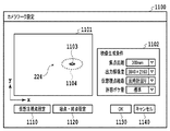
ステップ1001では、GUI制御部901によって、ユーザがカメラワーク設定を行うためのUI画面が表示操作部110に表示される。図11は、カメラワーク設定用のUI画面の一例を示す図である。UI画面1100内の左側の矩形領域1101は、仮想注視点の位置の指定、仮想視点の始点と終点の指定、複数の仮想視点候補の中からの選択等を行うためのカメラワーク設定領域である。UI画面1100におけるカメラワーク設定領域1101は、被撮影領域としてのフィールド220(図2を参照)を包含する一定範囲を上から見たxy平面上の矩形領域として表示されている。カメラワーク設定領域1101には、ユーザに被写体の位置を直観的に理解させるため、カメラ201〜210が取得した撮影画像を平面上に投影し合成したものが表示されている。さらに、例えば撮影シーンがサッカーの試合であれば、既知であるゴールポストの位置、センターライン、ペナルティエリア等の情報を合成表示或いは撮影画像の代替として表示してよい。また、UI画面1100内の右側の矩形領域1102は、自由視点映像生成に必要な各種パラメータを指定するための生成条件設定領域である。生成条件設定領域1102には、仮想カメラの焦点距離f´、出力解像度Rd、仮想視点の経路の種類、許容ボケ量b´の各項目について、予め用意された選択肢からユーザが所望の内容を指定可能なプルダウンメニューが設けられている。ここでは仮想カメラの移動の軌跡を円や楕円といった曲線であることを前提としているので、仮想視点経路の種類は時計回りと反時計回りとなっている。また許容ボケ量は、ユーザが数値を直観的に判断することが難しいため、例えば「大」「標準」「小」の3段階で選択肢を表示してユーザに選択させ、生成条件設定部305においてユーザ選択に対応した具体的な数値を割り当てる方式としている。なお、項目や項目内の内容は必要に応じて削除・追加してもよいし、プルダウンメニューに代えてスライドバーやラジオボタンを設けてもよい。「仮想注視点設定」ボタン1110は仮想注視点を、「始点・終点設定」ボタン1120は仮想視点の始点と終点をそれぞれ設定するためのボタンである。これらを押下するとカメラワーク設定領域1101内での位置指定が可能な状態になり、ユーザは例えばマウス等を用いて仮想注視点或いは仮想視点の始点と終点を指定する。「OK」ボタン1130及び「キャンセル」ボタン1140は、指定・選択した内容をユーザが確定させたり取り消したりするためのボタンである。
In
そして、カメラワーク設定領域1101内の任意の点(位置)が仮想注視点としてユーザによって指定されると、ステップ1002で、GUI制御部901はその情報を仮想注視点設定部301へ送る。受け取った情報に基づき、仮想注視点設定部301は仮想注視点の位置を設定する。ここでは、図2における被写体222の位置が仮想注視点の位置1103として設定されたものとする。また、生成条件についても同様に、GUI制御部901から受け取ったユーザ選択の情報に基づき、生成条件設定部302によって、仮想カメラの焦点距離f´、出力解像度Rd、仮想視点の種類、許容ボケ量b´の各項目の内容が設定される。
Then, when an arbitrary point (position) in the camera
ステップ1003では、撮影パラメータ取得部303においてカメラ201〜210の撮影パラメータが、多視点映像取得部308においてカメラ201〜210で撮影された多視点映像データがそれぞれ取得される。
In step 1003, the shooting
ステップ1004では、ボケ量導出部304において、ステップ1003で取得した撮影パラメータに基づき、ステップ1003で取得した多視点映像データの、ステップ1002で設定された仮想注視点におけるボケ量が導出される。
In step 1004, the blur
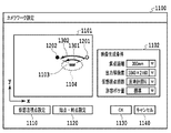
ステップ1005では、限界距離導出部903において、ステップ1002で設定された仮想注視点からみたxy平面上の各方位について、仮想視点が接近可能な限界距離が導出される。この限界距離は、生成対象の自由視点映像におけるボケ量が、ステップ1002で設定された許容ボケ量を超えることがないよう、その限度内で導出される。具体的には、設定された仮想注視点からみた各方位について、まず前述の式(6)及び式(7)を用いて参照画像の選択を行い、続いて前述の式(8)を用いて限界距離d´を求める。すなわち、実施例1では仮想視点位置から仮想注視点までの距離d´を固定値として仮想視点位置(仮想カメラ)の限界焦点距離を求めたが、本実施例では仮想カメラの焦点距離f´を固定値として仮想カメラが接近可能な限界距離d´を求めるものである。仮想注視点からみた各方位について導出された限界距離d´の情報はGUI制御部901に送られる。そして、GUI制御部901は、方位毎の限界距離値を仮想注視点位置1103を中心にプロットして図形化し、カメラワーク設定領域1101内に表示する。図11において、カメラワーク設定領域1101内に点線で示された楕円1104が、図形化された限界距離を示している。図形化された限界距離の内側を「接近不可領域」と呼ぶこととする。図11の例では、仮想注視点1103は実注視点224からx方向にずれているため、導出される限界距離はx方向で長くなり、y方向で短くなる。そのため、十分に細かい刻み幅で各方位の限界距離を求めた場合、図形化後の形状はx方向に長い楕円となる。なお、各方位の限界距離をユーザが把握できればよいので、例えば点線に代えて限界距離の範囲内を異なる色にするといったことで表現してもよい。
In step 1005, the limit
続いて、ユーザが「始点・終点設定」ボタン1120を押下すると、カメラワーク設定領域1101内に仮想視点の経路の始点と終点を設定するための設定バーが表示される。図12は、カメラワーク設定領域1101内に、始点設定バー1201と終点設定バー1202が表示された状態を示している。始点設定バー1201及び終点設定バー1202は、仮想注視点1103を一端とした線分であり、ユーザは例えばドラッグ操作によって始点設定バー1201及び終点設定バー1202を、仮想注視点1103を中心軸として任意の位置へ回転させることができる。ユーザが、これら設定バーを操作して始点と終点を指定し、「OK」ボタン1130を押下すると、当該指定された位置(方位)が、始点・終点設定部902によって、仮想視点経路の始点と終点として設定される(ステップ1006)。図11の例では、生成条件設定領域1102で仮想視点の種類として「反時計回り」が選択されているため、指定した始点の方位から終点の方位までの間を反時計回りに軌跡を描く仮想視点候補が次のステップで生成されることになる。
Subsequently, when the user presses the "start point / end point setting"
続くステップ1007では、ステップ1006で設定された始点と終点に基づき、上述の接近不可領域に入り込まないような経路の仮想視点候補が仮想視点候補生成部904によって、複数生成される。生成された仮想視点候補の情報はGUI制御部901に送られ、カメラワーク設定領域1101に表示される。図13及び図14は、仮想視点候補の一例を示す図である。図13に示す矢印1301は、設定された始点から終点までの間の全方位について限界距離まで仮想カメラが接近するような経路の仮想視点候補、矢印1302は限界距離から一定の間隔を取った、矢印1301と平行な軌跡を描く仮想視点候補をそれぞれ示している。また、図14に示す矢印1401は、設定された始点から終点までの間の全方位について仮想視点と仮想注視点との距離が一定であって可能な限りその距離を小さくした仮想視点候補、矢印1402は矢印1401よりもその距離を大きく取った場合の仮想視点候補をそれぞれ示している。なお、図13及び図14で示した仮想視点候補は一例であり、例えばこれらの中間の軌跡など、様々な仮想視点候補が考えられる。そこで、生成した仮想視点候補に基づき、例えば矢印1301と矢印1402、或いは矢印1401と1302の中間の軌跡を適当な係数で合成した仮想視点候補をさらに生成して表示するようにしてもよい。
In the following step 1007, a plurality of virtual viewpoint candidates of a route that does not enter the inaccessible region described above are generated by the virtual viewpoint
カメラワーク設定領域1101に表示された複数の仮想視点候補の中からユーザがマウス等を用いて任意の仮想視点候補を選択すると、GUI制御部901を介してその情報が仮想視点設定部302に送られる。仮想視点設定部302は、ユーザ選択に係る仮想視点候補を、自由視点映像生成に用いる仮想視点として設定する(ステップ1008)。設定された仮想視点の情報はカメラワーク設定部307に送られる。
When the user selects an arbitrary virtual viewpoint candidate from the plurality of virtual viewpoint candidates displayed in the camera
ステップ1009では、カメラワーク設定部307において、ステップ1008で設定された仮想視点に基づいてカメラワークを設定する。そして、ステップ1010で、自由視点映像生成部309によって、ステップ1008で設定されたカメラワークとステップ1002で取得した多視点映像データに基づいて、自由視点映像が生成される。
In step 1009, the camera
以上が、本実施例に係る自由視点映像生成処理の内容である。なお、上述のステップ1005〜1007の処理中にユーザが生成条件設定領域1102において、生成条件を変更した場合は、処理をステップ1004に戻し、仮想注視点におけるボケ量の抽出処理をやり直すことが望ましい。また、ステップ1007においてユーザが仮想視点の種類を変更(例えば、反時計回りを時計周りに変更)した場合は、当該変更後の内容に従った仮想視点候補を生成してもよいし、或いは始点設定バー1201と終点設定バー1202の役割を入れ替えて逆向きの仮想視点候補を生成するようにしてもよい。
The above is the content of the free-viewpoint video generation process according to this embodiment. If the user changes the generation condition in the generation
以上のとおり本実施例によっても、実施例1と同様、多視点映像データから自由視点映像を生成する場合において、ユーザに違和感を与えるようなボケの発生を抑制することができる。また、本実施例の場合はユーザの負担を軽減しつつ、自由度の高いカメラワークの設定が可能となる。 As described above, as in the first embodiment, it is possible to suppress the occurrence of blurring that gives the user a sense of discomfort when the free-viewpoint video is generated from the multi-viewpoint video data. Further, in the case of this embodiment, it is possible to set the camera work with a high degree of freedom while reducing the burden on the user.
先の実施例では、仮想視点の経路として円(楕円を含む)或いはその一部を用いたが、仮想視点の経路はこれに限定されない。例えば、実施例1においても視点・終点設定部を別途設け、ユーザが指定した始点と終点とを結ぶ直線経路の仮想視点を設定し、当該直線経路上の各位置における限界焦点距離を導出してカメラワークを設定するようにしてもよい。或いは実施例2において、UI画面1100内の生成条件設定領域1102で「仮想視点経路」の種類として“直線”を選択可能にし、ユーザがその始点と終点を指定することで、当該始点と終点とを結ぶ直線経路の仮想視点が設定されるように構成してもよい。この際、指定された始点と終点とを結ぶ直線と接近不可領域とが交差する場合に警告を出したり、或いは、接近不可領域と交差しないよう変形させた直線を仮想視点候補としてユーザに提示するように構成してもよい。
In the previous embodiment, a circle (including an ellipse) or a part thereof is used as the path of the virtual viewpoint, but the path of the virtual viewpoint is not limited to this. For example, also in the first embodiment, a viewpoint / end point setting unit is separately provided, a virtual viewpoint of a straight path connecting the start point and the end point specified by the user is set, and the limit focal length at each position on the straight path is derived. Camera work may be set. Alternatively, in the second embodiment, the generation
<その他の実施例>
本発明は、上述の実施形態の1以上の機能を実現するプログラムを、ネットワーク又は記憶媒体を介してシステム又は装置に供給し、そのシステム又は装置のコンピュータにおける1つ以上のプロセッサがプログラムを読出し実行する処理でも実現可能である。また、1以上の機能を実現する回路(例えば、ASIC)によっても実現可能である。
<Other Examples>
The present invention supplies a program that realizes one or more functions of the above-described embodiment to a system or device via a network or storage medium, and one or more processors in the computer of the system or device reads and executes the program. It can also be realized by the processing to be performed. It can also be realized by a circuit (for example, ASIC) that realizes one or more functions.
Claims (16)
前記撮影領域内のオブジェクトを指定する指定手段と、
前記指定手段による前記オブジェクトの指定と前記仮想視点の移動に係る所定の基準とに応じた前記仮想視点の移動経路を設定する設定手段であって、前記仮想視点の移動に伴う前記仮想視点画像における前記オブジェクトの画質の変化が抑えられるように、前記仮想視点の位置と前記仮想視点画像における前記オブジェクトの画質との関係に基づいて前記仮想視点の移動経路を設定する設定手段と、
を有することを特徴とする設定装置。 It is a setting device that sets the movement path of the virtual viewpoint in order to generate a virtual viewpoint image corresponding to the virtual viewpoint based on image data obtained by shooting the shooting area from different directions by a plurality of shooting devices. hand,
A designation means for designating an object in the shooting area and
A setting means for setting a movement path of the virtual viewpoint according to the designation of the object by the designating means and a predetermined reference related to the movement of the virtual viewpoint, and in the virtual viewpoint image accompanying the movement of the virtual viewpoint. Setting means for setting the movement path of the virtual viewpoint based on the relationship between the position of the virtual viewpoint and the image quality of the object in the virtual viewpoint image so that the change in the image quality of the object is suppressed.
A setting device characterized by having.
前記設定手段は、前記指定手段により指定されたオブジェクトと、前記取得手段により取得されたパラメータとに基づいて、前記仮想視点の移動経路を設定する、
ことを特徴とする請求項1又は2に記載の設定装置。 It has an acquisition means for acquiring a parameter related to the image quality of the virtual viewpoint image as the predetermined reference.
The setting means sets the movement path of the virtual viewpoint based on the object designated by the designated means and the parameters acquired by the acquisition means.
The setting device according to claim 1 or 2.
前記設定手段は、前記仮想視点の移動経路に従って生成される複数の仮想視点画像のそれぞれにおける前記オブジェクトの画質が前記最低画質よりも高くなるように、前記移動経路を設定する、
ことを特徴とする請求項3に記載の設定装置。 The parameters acquired by the acquisition means represent the lowest permissible image quality.
The setting means sets the movement path so that the image quality of the object in each of the plurality of virtual viewpoint images generated according to the movement path of the virtual viewpoint is higher than the minimum image quality.
The setting device according to claim 3, wherein the setting device is characterized by the above.
前記設定手段は、前記指定手段により指定されたオブジェクトと、前記取得手段により取得された前記移動経路のタイプとに基づいて、前記仮想視点の移動経路を設定する、
ことを特徴とする請求項1又は2に記載の設定装置。 It has an acquisition means for acquiring the type of the movement path of the virtual viewpoint as the predetermined reference.
The setting means sets the movement path of the virtual viewpoint based on the object designated by the designated means and the type of the movement path acquired by the acquisition means.
The setting device according to claim 1 or 2.
前記設定手段は、前記指定手段により指定されたオブジェクトと、前記取得手段により取得された前記1又は複数の仮想視点の位置とに基づいて、前記仮想視点の移動経路を設定する、
ことを特徴とする請求項1又は2に記載の設定装置。 It has an acquisition means for acquiring the position of one or a plurality of virtual viewpoints as the predetermined reference.
The setting means sets the movement path of the virtual viewpoint based on the object designated by the designated means and the position of the one or a plurality of virtual viewpoints acquired by the acquisition means.
The setting device according to claim 1 or 2.
前記撮影領域内のオブジェクトを指定する指定工程と、
前記指定工程における前記オブジェクトの指定と前記仮想視点の移動に係る所定の基準とに応じた前記仮想視点の移動経路を設定する設定工程であって、前記仮想視点の移動に伴う前記仮想視点画像における前記オブジェクトの画質の変化が抑えられるように、前記仮想視点の位置と前記仮想視点画像における前記オブジェクトの画質との関係に基づいて前記仮想視点の移動経路を設定する設定工程と、
を有することを特徴とする設定方法。 This is a setting method for setting the movement path of the virtual viewpoint in order to generate a virtual viewpoint image corresponding to the virtual viewpoint based on image data obtained by shooting the shooting area from different directions by a plurality of shooting devices. hand,
A designation process for designating an object in the shooting area and
In the setting step of setting the movement path of the virtual viewpoint according to the designation of the object and the predetermined reference related to the movement of the virtual viewpoint in the designated step, in the virtual viewpoint image accompanying the movement of the virtual viewpoint. A setting step of setting a movement path of the virtual viewpoint based on the relationship between the position of the virtual viewpoint and the image quality of the object in the virtual viewpoint image so that a change in the image quality of the object is suppressed.
A setting method characterized by having.
前記設定工程においては、前記指定工程において指定されたオブジェクトと、前記取得工程において取得された前記1又は複数の仮想視点の位置とに基づいて、前記仮想視点の移動経路が設定される、
ことを特徴とする請求項13に記載の設定方法。 It has an acquisition process of acquiring the position of one or a plurality of virtual viewpoints as the reference.
In the setting step, the movement path of the virtual viewpoint is set based on the object specified in the designated step and the position of the one or a plurality of virtual viewpoints acquired in the acquisition step.
13. The setting method according to claim 13.
前記設定工程においては、前記指定工程において指定されたオブジェクトと、前記取得工程において取得された前記画質に関するパラメータとに基づいて、前記仮想視点の移動経路が設定される、
ことを特徴とする請求項13に記載の設定方法。 It has an acquisition step of acquiring parameters related to the image quality of the virtual viewpoint image as the predetermined reference.
In the setting step, the movement path of the virtual viewpoint is set based on the object specified in the designated step and the parameters related to the image quality acquired in the acquisition step.
13. The setting method according to claim 13.
Priority Applications (3)
| Application Number | Priority Date | Filing Date | Title |
|---|---|---|---|
| JP2016253276A JP6849430B2 (en) | 2016-12-27 | 2016-12-27 | Image processing equipment, image processing methods, and programs |
| US15/852,238 US20180184072A1 (en) | 2016-12-27 | 2017-12-22 | Setting apparatus to set movement path of virtual viewpoint, setting method, and storage medium |
| EP17002070.5A EP3343515A1 (en) | 2016-12-27 | 2017-12-22 | Setting apparatus to set movement path of virtual viewpoint, setting method, and program |
Applications Claiming Priority (1)
| Application Number | Priority Date | Filing Date | Title |
|---|---|---|---|
| JP2016253276A JP6849430B2 (en) | 2016-12-27 | 2016-12-27 | Image processing equipment, image processing methods, and programs |
Publications (3)
| Publication Number | Publication Date |
|---|---|
| JP2018106496A JP2018106496A (en) | 2018-07-05 |
| JP2018106496A5 JP2018106496A5 (en) | 2020-02-06 |
| JP6849430B2 true JP6849430B2 (en) | 2021-03-24 |
Family
ID=60957009
Family Applications (1)
| Application Number | Title | Priority Date | Filing Date |
|---|---|---|---|
| JP2016253276A Active JP6849430B2 (en) | 2016-12-27 | 2016-12-27 | Image processing equipment, image processing methods, and programs |
Country Status (3)
| Country | Link |
|---|---|
| US (1) | US20180184072A1 (en) |
| EP (1) | EP3343515A1 (en) |
| JP (1) | JP6849430B2 (en) |
Families Citing this family (14)
| Publication number | Priority date | Publication date | Assignee | Title |
|---|---|---|---|---|
| JP2016046642A (en) * | 2014-08-21 | 2016-04-04 | キヤノン株式会社 | Information processing system, information processing method, and program |
| US10818064B2 (en) * | 2016-09-21 | 2020-10-27 | Intel Corporation | Estimating accurate face shape and texture from an image |
| JP7159057B2 (en) * | 2017-02-10 | 2022-10-24 | パナソニック インテレクチュアル プロパティ コーポレーション オブ アメリカ | Free-viewpoint video generation method and free-viewpoint video generation system |
| WO2019150450A1 (en) * | 2018-01-30 | 2019-08-08 | 株式会社ソニー・インタラクティブエンタテインメント | Image processing device and display image generation method |
| JP2019161462A (en) * | 2018-03-13 | 2019-09-19 | キヤノン株式会社 | Control device, image processing system, control method, and program |
| JP7207913B2 (en) * | 2018-09-07 | 2023-01-18 | キヤノン株式会社 | Information processing device, information processing method and program |
| JP7403956B2 (en) * | 2019-02-27 | 2023-12-25 | キヤノン株式会社 | Information processing device, control method, and program |
| JP7341674B2 (en) * | 2019-02-27 | 2023-09-11 | キヤノン株式会社 | Information processing device, information processing method and program |
| JP7394566B2 (en) * | 2019-09-15 | 2023-12-08 | 博文 伊藤 | Image processing device, image processing method, and image processing program |
| EP4083991A4 (en) * | 2019-12-23 | 2023-06-28 | Sony Group Corporation | Image generation device, image generation method, and image generation program |
| WO2021182153A1 (en) * | 2020-03-09 | 2021-09-16 | ソニーグループ株式会社 | Information processing device, information processing system, information processing method, and program |
| EP4016464A1 (en) * | 2020-11-26 | 2022-06-22 | Ricoh Company, Ltd. | Apparatus, system, method, and carrier means |
| JP2022182119A (en) * | 2021-05-27 | 2022-12-08 | キヤノン株式会社 | Image processing apparatus, control method thereof, and program |
| KR102518871B1 (en) * | 2021-12-03 | 2023-04-10 | 한국과학기술원 | Method and Apparatus for Framing a 3D Target Object for Generation of a Virtual Camera Layout |
Family Cites Families (44)
| Publication number | Priority date | Publication date | Assignee | Title |
|---|---|---|---|---|
| JP3787939B2 (en) * | 1997-02-27 | 2006-06-21 | コニカミノルタホールディングス株式会社 | 3D image display device |
| US6384820B2 (en) * | 1997-12-24 | 2002-05-07 | Intel Corporation | Method and apparatus for automated dynamics of three-dimensional graphics scenes for enhanced 3D visualization |
| US8014985B2 (en) * | 1999-03-26 | 2011-09-06 | Sony Corporation | Setting and visualizing a virtual camera and lens system in a computer graphic modeling environment |
| US20030076413A1 (en) * | 2001-10-23 | 2003-04-24 | Takeo Kanade | System and method for obtaining video of multiple moving fixation points within a dynamic scene |
| US7268804B2 (en) * | 2003-04-04 | 2007-09-11 | Stmicroelectronics, Inc. | Compound camera and method for synthesizing a virtual image from multiple input images |
| US7356164B2 (en) * | 2003-05-30 | 2008-04-08 | Lucent Technologies Inc. | Method and apparatus for finding feature correspondences between images captured in real-world environments |
| US7221366B2 (en) * | 2004-08-03 | 2007-05-22 | Microsoft Corporation | Real-time rendering system and process for interactive viewpoint video |
| JP4947593B2 (en) * | 2007-07-31 | 2012-06-06 | Kddi株式会社 | Apparatus and program for generating free viewpoint image by local region segmentation |
| US8089479B2 (en) * | 2008-04-11 | 2012-01-03 | Apple Inc. | Directing camera behavior in 3-D imaging system |
| WO2009128181A1 (en) * | 2008-04-18 | 2009-10-22 | 株式会社ソニー・コンピュータエンタテインメント | Image display device, method for controlling image display device, and information storage medium |
| JP5011224B2 (en) | 2008-07-09 | 2012-08-29 | 日本放送協会 | Arbitrary viewpoint video generation apparatus and arbitrary viewpoint video generation program |
| US8106924B2 (en) * | 2008-07-31 | 2012-01-31 | Stmicroelectronics S.R.L. | Method and system for video rendering, computer program product therefor |
| US8194995B2 (en) * | 2008-09-30 | 2012-06-05 | Sony Corporation | Fast camera auto-focus |
| US9619917B2 (en) * | 2008-10-03 | 2017-04-11 | Apple Inc. | Depth of field for a camera in a media-editing application |
| US9007379B1 (en) * | 2009-05-29 | 2015-04-14 | Two Pic Mc Llc | Methods and apparatus for interactive user control of virtual cameras |
| JP2011024017A (en) * | 2009-07-16 | 2011-02-03 | Sony Corp | Moving image extracting apparatus, program, and moving image extracting method |
| US8885022B2 (en) * | 2010-01-04 | 2014-11-11 | Disney Enterprises, Inc. | Virtual camera control using motion control systems for augmented reality |
| JP5570284B2 (en) * | 2010-04-16 | 2014-08-13 | キヤノン株式会社 | Image processing apparatus and method |
| CA2818695C (en) * | 2010-11-24 | 2018-06-26 | Google, Inc. | Guided navigation through geo-located panoramas |
| JP5858380B2 (en) * | 2010-12-03 | 2016-02-10 | 国立大学法人名古屋大学 | Virtual viewpoint image composition method and virtual viewpoint image composition system |
| JP5484631B2 (en) * | 2011-03-31 | 2014-05-07 | 富士フイルム株式会社 | Imaging apparatus, imaging method, program, and program storage medium |
| US8411195B2 (en) * | 2011-04-01 | 2013-04-02 | Sony Corporation | Focus direction detection confidence system and method |
| JP5921102B2 (en) * | 2011-07-19 | 2016-05-24 | 株式会社東芝 | Image processing system, apparatus, method and program |
| US9430055B2 (en) * | 2012-06-15 | 2016-08-30 | Microsoft Technology Licensing, Llc | Depth of field control for see-thru display |
| US10007348B2 (en) * | 2012-10-16 | 2018-06-26 | Jae Woong Jeon | Method and system for controlling virtual camera in virtual 3D space and computer-readable recording medium |
| US9305371B2 (en) * | 2013-03-14 | 2016-04-05 | Uber Technologies, Inc. | Translated view navigation for visualizations |
| US9396581B2 (en) * | 2013-10-18 | 2016-07-19 | Apple Inc. | Contact shadows in visual representations |
| US9361665B2 (en) * | 2013-11-27 | 2016-06-07 | Google Inc. | Methods and systems for viewing a three-dimensional (3D) virtual object |
| EP3014579B1 (en) * | 2014-04-30 | 2018-09-26 | Intel Corporation | System and method of limiting processing by a 3d reconstruction system of an environment in a 3d reconstruction of an event occurring in an event space |
| US9697608B1 (en) * | 2014-06-11 | 2017-07-04 | Amazon Technologies, Inc. | Approaches for scene-based object tracking |
| US9846968B2 (en) * | 2015-01-20 | 2017-12-19 | Microsoft Technology Licensing, Llc | Holographic bird's eye view camera |
| JP2016170522A (en) * | 2015-03-11 | 2016-09-23 | 株式会社東芝 | Moving body detection apparatus |
| US10102672B2 (en) * | 2015-03-16 | 2018-10-16 | Square Enix Co., Ltd. | Storage medium, information processing apparatus and control method |
| US10007967B2 (en) * | 2015-06-12 | 2018-06-26 | Gopro, Inc. | Temporal and spatial video noise reduction |
| JP6541454B2 (en) * | 2015-06-17 | 2019-07-10 | キヤノン株式会社 | Image processing apparatus, imaging apparatus, image processing method, image processing program, and storage medium |
| KR101671391B1 (en) * | 2015-07-07 | 2016-11-02 | 한국과학기술연구원 | Method for deblurring video using modeling blurred video with layers, recording medium and device for performing the method |
| JP6741009B2 (en) * | 2015-09-01 | 2020-08-19 | 日本電気株式会社 | Monitoring information generation device, shooting direction estimation device, monitoring information generation method, shooting direction estimation method, and program |
| JP6753405B2 (en) * | 2015-09-14 | 2020-09-09 | ソニー株式会社 | Information processing device and information processing method |
| JP6649742B2 (en) * | 2015-10-27 | 2020-02-19 | 株式会社コーエーテクモゲームス | Information processing apparatus, operation control method, and operation control program |
| US10628924B2 (en) * | 2015-12-14 | 2020-04-21 | Peking University Shenzhen Graduate School | Method and device for deblurring out-of-focus blurred images |
| EP3223245B1 (en) * | 2016-03-24 | 2024-04-24 | Ecole Nationale de l'Aviation Civile | Point of view selection in virtual 3d environment |
| JP6723820B2 (en) * | 2016-05-18 | 2020-07-15 | 株式会社デンソーテン | Image generation apparatus, image display system, and image display method |
| JP6776719B2 (en) * | 2016-08-17 | 2020-10-28 | 富士通株式会社 | Mobile group detection program, mobile group detection device, and mobile group detection method |
| US10609284B2 (en) * | 2016-10-22 | 2020-03-31 | Microsoft Technology Licensing, Llc | Controlling generation of hyperlapse from wide-angled, panoramic videos |
-
2016
- 2016-12-27 JP JP2016253276A patent/JP6849430B2/en active Active
-
2017
- 2017-12-22 EP EP17002070.5A patent/EP3343515A1/en not_active Withdrawn
- 2017-12-22 US US15/852,238 patent/US20180184072A1/en not_active Abandoned
Also Published As
| Publication number | Publication date |
|---|---|
| JP2018106496A (en) | 2018-07-05 |
| US20180184072A1 (en) | 2018-06-28 |
| EP3343515A1 (en) | 2018-07-04 |
Similar Documents
| Publication | Publication Date | Title |
|---|---|---|
| JP6849430B2 (en) | Image processing equipment, image processing methods, and programs | |
| JP7051457B2 (en) | Image processing equipment, image processing methods, and programs | |
| KR102187974B1 (en) | Information processing apparatus, method, and program for generation of virtual viewpoint images | |
| JP7146662B2 (en) | Image processing device, image processing method, and program | |
| US10970915B2 (en) | Virtual viewpoint setting apparatus that sets a virtual viewpoint according to a determined common image capturing area of a plurality of image capturing apparatuses, and related setting method and storage medium | |
| KR102162107B1 (en) | Image processing apparatus, image processing method and program | |
| JP7330683B2 (en) | Information processing device, information processing method and program | |
| US20160077422A1 (en) | Collaborative synchronized multi-device photography | |
| CN106464810B (en) | Control device, control method, and program | |
| JP7073092B2 (en) | Image processing equipment, image processing methods and programs | |
| US20150177062A1 (en) | Information processing apparatus, information processing method, and storage medium | |
| US11956408B2 (en) | Information processing system, information processing method, and storage medium | |
| JP2019003428A (en) | Image processing device, image processing method, and program | |
| JP2014027528A (en) | Projection transformation video generation device, program of the same and multi-viewpoint video expression device | |
| JP2016039613A (en) | Image processing system, control method thereof, program, and storage medium | |
| KR101219859B1 (en) | Apparatus and method for semi-auto convergence in 3d photographing apparatus | |
| JP2019144958A (en) | Image processing device, image processing method, and program | |
| JP7297515B2 (en) | Information processing device, information processing method and program | |
| JP2020014177A5 (en) | ||
| JP7130976B2 (en) | Display information creation device, imaging system and program | |
| JP2023175503A (en) | Image processing apparatus and its image processing method | |
| JP2023003765A (en) | Image generation device and control method thereof, image generation system, and program | |
| JP2022083816A (en) | Image generation apparatus, image generation method, and program | |
| JP6282103B2 (en) | Image processing apparatus, image processing method, and program. | |
| JP2023122130A (en) | Video processing device, control method thereof, and program |
Legal Events
| Date | Code | Title | Description |
|---|---|---|---|
| A521 | Request for written amendment filed |
Free format text: JAPANESE INTERMEDIATE CODE: A523 Effective date: 20191220 |
|
| A621 | Written request for application examination |
Free format text: JAPANESE INTERMEDIATE CODE: A621 Effective date: 20191220 |
|
| A977 | Report on retrieval |
Free format text: JAPANESE INTERMEDIATE CODE: A971007 Effective date: 20210128 |
|
| TRDD | Decision of grant or rejection written | ||
| A01 | Written decision to grant a patent or to grant a registration (utility model) |
Free format text: JAPANESE INTERMEDIATE CODE: A01 Effective date: 20210202 |
|
| A61 | First payment of annual fees (during grant procedure) |
Free format text: JAPANESE INTERMEDIATE CODE: A61 Effective date: 20210304 |
|
| R151 | Written notification of patent or utility model registration |
Ref document number: 6849430 Country of ref document: JP Free format text: JAPANESE INTERMEDIATE CODE: R151 |