JP6848603B2 - Game machine - Google Patents
Game machine Download PDFInfo
- Publication number
- JP6848603B2 JP6848603B2 JP2017066432A JP2017066432A JP6848603B2 JP 6848603 B2 JP6848603 B2 JP 6848603B2 JP 2017066432 A JP2017066432 A JP 2017066432A JP 2017066432 A JP2017066432 A JP 2017066432A JP 6848603 B2 JP6848603 B2 JP 6848603B2
- Authority
- JP
- Japan
- Prior art keywords
- ball
- opening
- state
- game
- round
- Prior art date
- Legal status (The legal status is an assumption and is not a legal conclusion. Google has not performed a legal analysis and makes no representation as to the accuracy of the status listed.)
- Active
Links
- 238000001514 detection method Methods 0.000 claims description 140
- 238000005096 rolling process Methods 0.000 claims description 67
- 238000011144 upstream manufacturing Methods 0.000 claims description 48
- 238000007599 discharging Methods 0.000 claims description 16
- 230000000903 blocking effect Effects 0.000 claims description 6
- 238000003860 storage Methods 0.000 description 193
- 238000009826 distribution Methods 0.000 description 110
- 230000008859 change Effects 0.000 description 88
- 230000000694 effects Effects 0.000 description 83
- 230000005540 biological transmission Effects 0.000 description 80
- 102100024061 Integrator complex subunit 1 Human genes 0.000 description 60
- 101710092857 Integrator complex subunit 1 Proteins 0.000 description 60
- 230000001105 regulatory effect Effects 0.000 description 58
- 238000004891 communication Methods 0.000 description 40
- 238000010586 diagram Methods 0.000 description 34
- 230000033001 locomotion Effects 0.000 description 34
- 238000000034 method Methods 0.000 description 33
- 230000036961 partial effect Effects 0.000 description 32
- 102100033265 Integrator complex subunit 2 Human genes 0.000 description 28
- 108050002021 Integrator complex subunit 2 Proteins 0.000 description 28
- 230000033228 biological regulation Effects 0.000 description 26
- 230000001965 increasing effect Effects 0.000 description 26
- 230000002265 prevention Effects 0.000 description 22
- 230000009471 action Effects 0.000 description 21
- 230000002829 reductive effect Effects 0.000 description 21
- 230000001174 ascending effect Effects 0.000 description 20
- 230000004308 accommodation Effects 0.000 description 17
- 238000013461 design Methods 0.000 description 17
- 230000003111 delayed effect Effects 0.000 description 15
- 230000009467 reduction Effects 0.000 description 15
- 230000007423 decrease Effects 0.000 description 14
- 230000008569 process Effects 0.000 description 14
- 230000002452 interceptive effect Effects 0.000 description 11
- 238000004519 manufacturing process Methods 0.000 description 11
- 230000001276 controlling effect Effects 0.000 description 9
- 102100033263 Integrator complex subunit 3 Human genes 0.000 description 8
- 101710092886 Integrator complex subunit 3 Proteins 0.000 description 8
- 230000008901 benefit Effects 0.000 description 8
- 230000005284 excitation Effects 0.000 description 8
- 230000007774 longterm Effects 0.000 description 8
- 238000010304 firing Methods 0.000 description 7
- 239000011521 glass Substances 0.000 description 7
- 239000004973 liquid crystal related substance Substances 0.000 description 7
- 238000012423 maintenance Methods 0.000 description 7
- 238000006073 displacement reaction Methods 0.000 description 6
- 238000012544 monitoring process Methods 0.000 description 6
- 230000004044 response Effects 0.000 description 6
- 238000007789 sealing Methods 0.000 description 6
- 230000001960 triggered effect Effects 0.000 description 6
- 210000000078 claw Anatomy 0.000 description 5
- 230000001788 irregular Effects 0.000 description 5
- 239000000463 material Substances 0.000 description 5
- 238000003825 pressing Methods 0.000 description 5
- 239000011347 resin Substances 0.000 description 5
- 229920005989 resin Polymers 0.000 description 5
- 230000006399 behavior Effects 0.000 description 4
- 230000005281 excited state Effects 0.000 description 4
- 238000005286 illumination Methods 0.000 description 4
- 239000002184 metal Substances 0.000 description 4
- 230000007704 transition Effects 0.000 description 4
- XLYOFNOQVPJJNP-UHFFFAOYSA-N water Substances O XLYOFNOQVPJJNP-UHFFFAOYSA-N 0.000 description 4
- 210000001015 abdomen Anatomy 0.000 description 3
- 230000005856 abnormality Effects 0.000 description 3
- 230000006870 function Effects 0.000 description 3
- 230000006872 improvement Effects 0.000 description 3
- 230000002093 peripheral effect Effects 0.000 description 3
- 238000004904 shortening Methods 0.000 description 3
- 239000000758 substrate Substances 0.000 description 3
- 230000001133 acceleration Effects 0.000 description 2
- 230000003466 anti-cipated effect Effects 0.000 description 2
- 230000009286 beneficial effect Effects 0.000 description 2
- 230000015572 biosynthetic process Effects 0.000 description 2
- 230000004397 blinking Effects 0.000 description 2
- 239000003086 colorant Substances 0.000 description 2
- 230000005484 gravity Effects 0.000 description 2
- 230000001771 impaired effect Effects 0.000 description 2
- 238000009434 installation Methods 0.000 description 2
- 230000007246 mechanism Effects 0.000 description 2
- 238000007747 plating Methods 0.000 description 2
- 238000012545 processing Methods 0.000 description 2
- 230000008439 repair process Effects 0.000 description 2
- 238000000926 separation method Methods 0.000 description 2
- 230000007103 stamina Effects 0.000 description 2
- VYZAMTAEIAYCRO-UHFFFAOYSA-N Chromium Chemical compound [Cr] VYZAMTAEIAYCRO-UHFFFAOYSA-N 0.000 description 1
- 241000287127 Passeridae Species 0.000 description 1
- 206010067171 Regurgitation Diseases 0.000 description 1
- 238000009825 accumulation Methods 0.000 description 1
- 229920000122 acrylonitrile butadiene styrene Polymers 0.000 description 1
- 238000013459 approach Methods 0.000 description 1
- 238000005452 bending Methods 0.000 description 1
- 230000015556 catabolic process Effects 0.000 description 1
- 239000003795 chemical substances by application Substances 0.000 description 1
- 239000012141 concentrate Substances 0.000 description 1
- 238000007796 conventional method Methods 0.000 description 1
- 230000001934 delay Effects 0.000 description 1
- 238000011161 development Methods 0.000 description 1
- 238000005553 drilling Methods 0.000 description 1
- 230000008030 elimination Effects 0.000 description 1
- 238000003379 elimination reaction Methods 0.000 description 1
- 230000002708 enhancing effect Effects 0.000 description 1
- 239000005357 flat glass Substances 0.000 description 1
- 230000000670 limiting effect Effects 0.000 description 1
- 230000013011 mating Effects 0.000 description 1
- 230000002035 prolonged effect Effects 0.000 description 1
- 230000001681 protective effect Effects 0.000 description 1
- 230000004043 responsiveness Effects 0.000 description 1
- 230000000717 retained effect Effects 0.000 description 1
- 238000010079 rubber tapping Methods 0.000 description 1
- 210000004243 sweat Anatomy 0.000 description 1
- 230000001360 synchronised effect Effects 0.000 description 1
- 238000012546 transfer Methods 0.000 description 1
Images


Description
本発明は、パチンコ機などの遊技機に関するものである。 The present invention relates to a gaming machine such as a pachinko machine.
ここで、パチンコ機等の遊技機において、入球口へ球を案内可能な状態と入球口へ球を案内不能な状態とで切り替えられる入球切替手段を備える遊技機がある(特許文献1)。 Here, in the gaming machine of the pachinko machine or the like, there is a gaming machine having a ball entrance switching means to be switched between the guide a condition not a sphere to sphere can guide state and ball entrance port to enter the sphere outlet (Patent Document 1 ).
しかしながら、上述した従来の遊技機では、入球切替手段の状態の切り替えに関して改善の余地があるという問題点があった。 However, the above-mentioned conventional game machine has a problem that there is room for improvement in switching the state of the ball entry switching means.
本発明は、上記例示した問題点を解決するためになされたものであり、入球切替手段の状態の切り替えに関して改善することができる遊技機を提供することを目的とする。 The present invention has been made to solve the above-exemplified problems, and an object of the present invention is to provide a game machine capable of improving the switching of the state of the ball entry switching means.
この目的を達成するために請求項1記載の遊技機は、球が流下する遊技領域と、その遊技領域を流下した球が通過する入球口と、その入球口の上流側から流下する球を前記入球口へ案内可能な第1状態と前記入球口の上流側から流下する球を前記入球口へ案内不能な第2状態とで切り替えられる入球切替手段と、前記入球口への入球を検出する検出手段と、を備える遊技機であって、前記入球口を通過した球が所定個数まで同時に存在可能な所定空間を構成する空間構成手段と、前記入球切替手段が前記第2状態に切り替えられた状態において前記所定空間に存在している球を前記所定空間から排出可能な排出手段とを備え、前記所定空間に球が存在している状態で前記入球切替手段を前記第1状態に切替可能に構成され、前記所定空間に存在している遊技球が視認可能に構成され、前記第1状態においても球を前記所定空間から排出可能に構成され、前記入球切替手段は、球が転動可能な転動部と、前記入球口側への球の流下を遮断可能な遮断部とを備え、前記転動部と前記遮断部とが一体的に動作可能に構成される。
In order to achieve this object, the gaming machine according to
請求項2記載の遊技機は、請求項1記載の遊技機において、基板ボックスを備える。The gaming machine according to
請求項1記載の遊技機によれば、入球切替手段の状態の切り替えに関して改善することができる。
According to the gaming machine according to
請求項2記載の遊技機によれば、請求項1記載の遊技機の奏する効果に加え、基板ボックスに基板を収容することができる。According to the gaming machine according to
以下、本発明の実施形態について、添付図面を参照して説明する。まず、図1から図23を参照し、第1実施形態として、本発明をパチンコ遊技機(以下、単に「パチンコ機」という)10に適用した場合の一実施形態について説明する。図1は、第1実施形態におけるパチンコ機10の正面図であり、図2はパチンコ機10の遊技盤13の正面図であり、図3はパチンコ機10の背面図である。
Hereinafter, embodiments of the present invention will be described with reference to the accompanying drawings. First, with reference to FIGS. 1 to 23, as a first embodiment, an embodiment when the present invention is applied to a pachinko gaming machine (hereinafter, simply referred to as “pachinko machine”) 10 will be described. FIG. 1 is a front view of the
図1に示すように、パチンコ機10は、略矩形状に組み合わせた木枠により外殻が形成される外枠11と、その外枠11と略同一の外形形状に形成され外枠11に対して開閉可能に支持された内枠12とを備えている。外枠11には、内枠12を支持するために正面視(図1参照)左側の上下2カ所に金属製のヒンジ18が取り付けられ、そのヒンジ18が設けられた側を開閉の軸として内枠12が正面手前側へ開閉可能に支持されている。
As shown in FIG. 1, the
内枠12には、多数の釘や入賞口63,64等を有する遊技盤13(図2参照)が裏面側から着脱可能に装着される。この遊技盤13の正面を球(以下、遊技球やパチンコ球とも称す)が流下することにより弾球遊技が行われる。なお、内枠12には、球を遊技盤13の正面領域に発射する球発射ユニット112a(図4参照)やその球発射ユニット112aから発射された球を遊技盤13の正面領域まで誘導する発射レール(図示せず)等が取り付けられている。
A game board 13 (see FIG. 2) having a large number of nails, winning
内枠12の正面側には、その正面上側を覆う正面枠14と、その下側を覆う下皿ユニット15とが設けられている。正面枠14及び下皿ユニット15を支持するために正面視(図1参照)左側の上下2カ所に金属製のヒンジ19が取り付けられ、そのヒンジ19が設けられた側を開閉の軸として正面枠14及び下皿ユニット15が正面手前側へ開閉可能に支持されている。なお、内枠12の施錠と正面枠14の施錠とは、シリンダ錠20の鍵穴21に専用の鍵を差し込んで所定の操作を行うことでそれぞれ解除される。
On the front side of the
正面枠14は、装飾用の樹脂部品や電気部品等を組み付けたものであり、その略中央部には略楕円形状に開口形成された窓部14cが設けられている。正面枠14の裏面側には2枚の板ガラスを有するガラスユニット16が配設され、そのガラスユニット16を介して遊技盤13の正面がパチンコ機10の正面側に視認可能となっている。
The
正面枠14には、球を貯留する上皿17が正面側へ張り出して上面を開放した略箱状に形成されており、この上皿17に賞球や貸出球などが排出される。上皿17の底面は正面視(図1参照)右側に下降傾斜して形成され、その傾斜により上皿17に投入された球が球発射ユニット112a(図4参照)へと案内される。また、上皿17の上面には、枠ボタン22が設けられている。この枠ボタン22は、例えば、第3図柄表示装置81(図2参照)で表示される演出のステージを変更したり、スーパーリーチの演出内容を変更したりする場合などに、遊技者により操作される。
In the
正面枠14には、その周囲(例えばコーナー部分)に各種ランプ等の発光手段が設けられている。これら発光手段は、大当たり時や所定のリーチ時等における遊技状態の変化に応じて、点灯又は点滅することにより発光態様が変更制御され、遊技中の演出効果を高める役割を果たす。窓部14cの周縁には、LED等の発光手段を内蔵した電飾部29〜33が設けられている。パチンコ機10においては、これら電飾部29〜33が大当たりランプ等の演出ランプとして機能し、大当たり時やリーチ演出時等には内蔵するLEDの点灯や点滅によって各電飾部29〜33が点灯または点滅して、大当たり中である旨、或いは大当たり一歩手前のリーチ中である旨が報知される。また、正面枠14の正面視(図1参照)左上部には、LED等の発光手段が内蔵され賞球の払い出し中とエラー発生時とを表示可能な表示ランプ34が設けられている。
The
また、右側の電飾部32下側には、正面枠14の裏面側を視認できるように裏面側より透明樹脂を取り付けて小窓35が形成され、遊技盤13正面の貼着スペースK1(図2参照)に貼付される証紙等がパチンコ機10の正面から視認可能とされている。また、パチンコ機10においては、より煌びやかさを醸し出すために、電飾部29〜33の周りの領域にクロムメッキを施したABS樹脂製のメッキ部材36が取り付けられている。
Further, on the lower side of the illuminated
窓部14cの下方には、貸球操作部40が配設されている。貸球操作部40には、度数表示部41と、球貸しボタン42と、返却ボタン43とが設けられている。パチンコ機10の側方に配置されるカードユニット(球貸しユニット)(図示せず)に紙幣やカード等を投入した状態で貸球操作部40が操作されると、その操作に応じて球の貸出が行われる。具体的には、度数表示部41はカード等の残額情報が表示される領域であり、内蔵されたLEDが点灯して残額情報として残額が数字で表示される。球貸しボタン42は、カード等(記録媒体)に記録された情報に基づいて貸出球を得るために操作されるものであり、カード等に残額が存在する限りにおいて貸出球が上皿17に供給される。返却ボタン43は、カードユニットに挿入されたカード等の返却を求める際に操作される。なお、カードユニットを介さずに球貸し装置等から上皿17に球が直接貸し出されるパチンコ機、いわゆる現金機では貸球操作部40が不要となるが、この場合には、貸球操作部40の設置部分に飾りシール等を付加して部品構成は共通のものとしても良い。カードユニットを用いたパチンコ機と現金機との共通化を図ることができる。
A ball
上皿17の下側に位置する下皿ユニット15には、その中央部に上皿17に貯留しきれなかった球を貯留するための下皿50が上面を開放した略箱状に形成されている。下皿50の右側には、球を遊技盤13の正面へ打ち込むために遊技者によって操作される操作ハンドル51が配設される。
In the
操作ハンドル51の内部には、球発射ユニット112aの駆動を許可するためのタッチセンサ51aと、押下操作している期間中には球の発射を停止する発射停止スイッチ51bと、操作ハンドル51の回動操作量(回動位置)を電気抵抗の変化により検出する可変抵抗器(図示せず)などが内蔵されている。操作ハンドル51が遊技者によって右回りに回動操作されると、タッチセンサ51aがオンされると共に可変抵抗器の抵抗値が回動操作量に対応して変化し、その可変抵抗器の抵抗値に対応した強さ(発射強度)で球が発射され、これにより遊技者の操作に対応した飛び量で遊技盤13の正面へ球が打ち込まれる。また、操作ハンドル51が遊技者により操作されていない状態においては、タッチセンサ51aおよび発射停止スイッチ51bがオフとなっている。
Inside the
下皿50の正面下方部には、下皿50に貯留された球を下方へ排出する際に操作するための球抜きレバー52が設けられている。この球抜きレバー52は、常時、右方向に付勢されており、その付勢に抗して左方向へスライドさせることにより、下皿50の底面に形成された底面口が開口して、その底面口から球が自然落下して排出される。この球抜きレバー52の操作は、通常、下皿50の下方に下皿50から排出された球を受け取る箱(一般に「千両箱」と称される)を置いた状態で行われる。下皿50の右方には、上述したように操作ハンドル51が配設され、下皿50の左方には灰皿53が取り付けられている。
A
図2に示すように、遊技盤13は、正面視略正方形状に切削加工したベース板60に、球案内用の多数の釘や風車の他、レール61,62、一般入賞口63、第1入球口64、第2入球口640、第一可変入賞装置1000、普通入球口(スルーゲート)67、可変表示装置ユニット80等を組み付けて構成され、その周縁部が内枠12(図1参照)の裏面側に取り付けられる。ベース板60は光透過性の樹脂材料からなり、その正面側からベース板60の背面側に配設された各種構造体を遊技者に視認させることが可能に形成される。一般入賞口63、第1入球口64、第2入球口640、第一可変入賞装置1000、可変表示装置ユニット80は、ルータ加工によってベース板60に形成された貫通穴に配設され、遊技盤13の正面側からタッピングネジ等により固定されている。
As shown in FIG. 2, the
遊技盤13の正面中央部分は、正面枠14の窓部14c(図1参照)を通じて内枠12の正面側から視認することができる。以下に、主に図2を参照して、遊技盤13の構成について説明する。
The front central portion of the
遊技盤13の正面には、帯状の金属板を略円弧状に屈曲加工して形成した外レール62が植立され、その外レール62の内側位置には外レール62と同様に帯状の金属板で形成した円弧状の内レール61が植立される。この内レール61と外レール62とにより遊技盤13の正面外周が囲まれ、遊技盤13とガラスユニット16(図1参照)とにより前後が囲まれることにより、遊技盤13の正面には、球の挙動により遊技が行われる遊技領域が形成される。遊技領域は、遊技盤13の正面であって2本のレール61,62とレール間を繋ぐ樹脂製の円弧部材70とにより区画して形成される領域(入賞口等が配設され、発射された球が流下する領域)である。
An
2本のレール61,62は、球発射ユニット112a(図4参照)から発射された球を遊技盤13上部へ案内するために設けられたものである。内レール61の先端部分(図2の左上部)には戻り球防止部材68が取り付けられ、一旦、遊技盤13の上部へ案内された球が再度球案内通路内に戻ってしまうといった事態が防止される。外レール62の先端部(図2の右上部)には、球の最大飛翔部分に対応する位置に返しゴム69が取り付けられ、所定以上の勢いで発射された球は、返しゴム69に当たって、勢いが減衰されつつ中央部側へ跳ね返される。また、内レール61の右下側の先端部と外レール62の右上側の先端部との間には、レール間を繋ぐ円弧を内面側に設けて形成された樹脂製の円弧部材70がベース板60に打ち込んで固定されている。
The two
本パチンコ機10では、第1入球口64、および第2入球口640へ入賞があったことを契機として特別図柄(第1図柄)の抽選が行われ、球が普通入球口67を通過した場合に普通図柄(第2図柄)の抽選が行われる。第1入球口64、および第2入球口640への入球に対して行われる特別図柄の抽選では、特別図柄の大当たりか否かの当否判定が行われると共に、特別図柄の大当たりと判定された場合にはその大当たり種別の判定も行われる。なお、本パチンコ機10では、特別図柄の低確率状態では、例えば、320分の1の確率で特別図柄の大当たりと判定され、特別図柄の高確率状態(特別図柄の確変状態とも称する)では、例えば、60分の1の確率で特別図柄の大当たりと判定される。なお、説明の便宜上、第1入球口64への入球に対して行われる特別図柄の抽選を「特別図柄1の抽選」と称し、第2入球口640への入球に対して行われる特別図柄の抽選を「特別図柄2の抽選」と称する。
In this
特別図柄の大当たりになると、パチンコ機10が特別遊技状態へ移行すると共に、通常時には閉鎖されている第1特定入賞口1000aが所定時間(例えば、30秒経過するまで、或いは、球が10個入賞するまで)開放される動作が最大15回(15ラウンド)繰り返される。その結果、その第1特定入賞口1000aに多量の球が入賞するので、通常時より多量の賞球の払い出しが行われる。
When the jackpot of the special symbol is reached, the
なお、特別図柄の大当たり種別としては、「大当たりA」、「大当たりB」、「大当たりC」、「大当たりa」、「大当たりb」、「大当たりc」の6種類が設けられている(図22参照)。詳細については後述するが、大当たり種別によって、第1特定入賞口1000aの開放パターンが異なって構成されており、第1可変入賞装置1000への球の入球個数を変化させるように構成される。
There are six types of special symbols, "Big hit A", "Big hit B", "Big hit C", "Big hit a", "Big hit b", and "Big hit c" (FIG. 22). reference). Although the details will be described later, the opening pattern of the first specific winning
特別図柄(第1図柄)の抽選が行われると、第1図柄表示装置37において特別図柄の変動表示が開始されて、所定時間(例えば、11秒〜60秒など)が経過した後に、抽選結果を示す特別図柄が停止表示される。第1図柄表示装置37において変動表示が行われている間に球が第1入球口64、または第2入球口640へと入球すると、その入球回数は入球口の種別毎にそれぞれ最大4回まで保留され、その保留球数が第1図柄表示装置37により示されると共に、第3図柄表示装置81においても示される。第1図柄表示装置37において変動表示が終了した場合に、第1入球口64についての保留球数(特別図柄1の保留球数)、または第2入球口640についての保留球数(特別図柄2の保留球数)が残っていれば、次の特別図柄の抽選が行われると共に、その抽選に応じた変動表示が開始される。なお、特別図柄1の保留球数と特別図柄2の保留球数が共に残っている場合は、特別図柄2の保留球に基づく抽選が優先的に実行される。
When the lottery of the special symbol (first symbol) is performed, the variable display of the special symbol is started on the first
普通図柄(第2図柄)の抽選では、普通図柄の当たりか否かの当否判定が行われる。普通図柄の当たりになると、所定時間(例えば、0.2秒または1秒)だけ第2入球口640に付随する電動役物640aが開放され、第2入球口640へ球が入球し易い状態になる。つまり、普通図柄の当たりになると、球が第2入球口640へ入球し易くなり、その結果、特別図柄の抽選が行われ易くなる。
In the lottery of the normal symbol (second symbol), it is determined whether or not the normal symbol is a hit. When the normal symbol hits, the
また、普通図柄(第2図柄)の抽選が行われると、第2図柄表示装置83において普通図柄の変動表示が開始されて、所定時間(例えば、3秒や30秒など)が経過した後に、抽選結果を示す普通図柄が停止表示される。第2図柄表示装置83において変動表示が行われている間に球が普通入球口67を通過すると、その通過回数は最大4回まで保留され、その保留球数が第1図柄表示装置37により表示されると共に、第2図柄保留ランプ84においても示される。第2図柄表示装置83において変動表示が終了した場合に、普通入球口67についての保留球数が残っていれば、次の普通図柄の抽選が行われると共に、その抽選に応じた変動表示が開始される。
Further, when the lottery of the normal symbol (second symbol) is performed, the variable display of the normal symbol is started on the second
本実施形態では、大当たり終了後の付加価値として、特別遊技状態が終了してから特別図柄の抽選が100回終了するまで特別図柄の確変状態(高確率状態)が付与され、特別図柄の抽選が100回終了して以降は通常状態に設定されるように構成される。
In the present embodiment, as an added value after the end of the jackpot, a probabilistic state (high probability state) of the special symbol is given from the end of the special game state to the end of the lottery of the
なお、本実施形態では、特別遊技状態の終了後に特別図柄の確変状態が付与される場合に、その特別図柄の確変状態が特別図柄の抽選の回数に応じて終了するように構成したが、これに限られるものではなく、例えば、所定の大当たり種別(例えば、後述する大当たりA、大当たりB、大当たりa)の大当たり遊技の後に、その大当たり終了後から次に大当たりとなるまでの間、パチンコ機10が特別図柄の高確率状態(特別図柄の確変中)へ移行するようにしても良い。この場合、他の大当たり種別(例えば、後述する大当たりC、大当たりb、大当たりc)の大当たり遊技の後に、特別図柄の抽選が100回終了するまで普通図柄の時短状態となるように構成される。
In the present embodiment, when the probabilistic state of the special symbol is given after the end of the special gaming state, the probabilistic state of the special symbol is configured to end according to the number of lottery of the special symbol. The
なお、上述した特別図柄の確変状態(高確率状態)が付与される特別図柄の抽選回数は、100回に限られるものではない。例えば、50回でも良いし、200回でも良い。 The number of lottery of the special symbol to which the above-mentioned probability variation state (high probability state) of the special symbol is given is not limited to 100 times. For example, it may be 50 times or 200 times.
また、上述した普通図柄の時短状態となる特別図柄の抽選回数は、100回に限られる物ではない。例えば、50回でも良いし、5回でも良い。 Further, the number of lottery times for the special symbols described above in which the time is shortened is not limited to 100 times. For example, it may be 50 times or 5 times.
ここで、「特別図柄の高確率状態」とは、大当たり終了後に付加価値としてその後の大当たり確率がアップした状態、いわゆる確率変動中(確変中)の時をいい、換言すれば、特別遊技状態へ移行し易い遊技の状態のことである。本実施形態における特別図柄の高確率状態(特別図柄の確変中)は、普通図柄(第2図柄)の当たり確率がアップして第2入球口640へ球が入賞し易い遊技の状態を含む。一方、「特別図柄の低確率状態」とは、特別図柄の確変中でない時をいい、大当たり確率が通常の状態、即ち、特別図柄の確変中よりも大当たり確率が低い状態をいう。
Here, the "high probability state of the special symbol" refers to a state in which the probability of the subsequent jackpot is increased as an added value after the end of the jackpot, that is, during the so-called probability fluctuation (probability change), in other words, to the special gaming state. It is a state of the game that is easy to shift. The high-probability state of the special symbol (during the probability change of the special symbol) in the present embodiment includes the state of the game in which the hit probability of the normal symbol (second symbol) is increased and the ball is easily won in the
また、普通図柄の時短状態(時短中)とは、普通図柄の当たり確率がアップして第2入球口640へ球が入賞し易い遊技の状態のことをいう。また、通常状態とは、特別図柄の確変中でも普通図柄の時短中でもない遊技の状態(大当たり確率も普通図柄(第2図柄)の当たり確率もアップしていない状態)のことをいう。
In addition, the time saving state of the normal symbol (during the time saving) is a state of the game in which the probability of hitting the normal symbol is increased and the ball is easily won in the
特別図柄の確変中や、普通図柄の時短中では、普通図柄の当たり確率がアップするだけではなく、第2入球口640に付随する電動役物640aが開放される時間も変更され、通常状態に比較して長い時間が設定される。電動役物640aが開放された状態(開放状態)にある場合は、その電動役物640aが閉鎖された状態(閉鎖状態)にある場合と比較して、第2入球口640へ球が入賞しやすい状態となる。よって、特別図柄の確変中や普通図柄の時短中は、第2入球口640へ球が入球し易い状態となる。即ち、特別図柄の抽選が行われやすくなる。
During the probability change of the special symbol or the time reduction of the normal symbol, not only the probability of hitting the normal symbol increases, but also the time when the
なお、特別図柄の確変中や普通図柄の時短中において、第2入球口640に付随する電動役物640aの開放時間を変更するのではなく、または、その開放時間を変更することに加えて、普通図柄の当たりとなった場合における電動役物640aの開放回数を、通常状態よりも増やすように構成してもよい。また、特別図柄の確変中や普通図柄の時短中において、普通図柄(第2図柄)の当たり確率は変更せず、第2入球口640に付随する電動役物640aが開放される時間、および電動役物640aの開放回数のうち少なくとも一方を変更するものとしてもよい。また、特別図柄の確変中や普通図柄の時短中において、第2入球口640に付随する電動役物640aが開放される時間や、電動役物640aの開放回数は変更せず、普通図柄(第2図柄)の当たり確率だけを、通常状態に比較してアップするように構成してもよい。
It should be noted that, during the probability change of the special symbol or the time reduction of the normal symbol, the opening time of the
遊技領域の正面視左側下部(図2の左側下部)には、発光手段である複数の発光ダイオード(以下、「LED」と略す)37aと7セグメント表示器37bとが設けられた第1図柄表示装置37が配設されている。第1図柄表示装置37は、後述する主制御装置110で行われる各制御に応じた表示がなされるものであり、主にパチンコ機10の遊技状態の表示が行われる。複数のLED37aは、第1入球口64、または第2入球口640への入球(始動入賞)に伴って行われる特別図柄の抽選が実行中であるか否かを点灯状態により示すことによって変動表示を行ったり、変動終了後の停止図柄として、その特別図柄の抽選結果に応じた特別図柄(第1図柄)を点灯状態により示したり、第1入球口64に入球された球のうち変動が未実行である球(保留球)の数である保留球数を点灯状態により示すものである。
A first symbol display provided with a plurality of light emitting diodes (hereinafter abbreviated as "LED") 37a and a 7-
この第1図柄表示装置37において特別図柄(第1図柄)の変動表示が行われている間に球が第1入球口64、または第2入球口640へと入球した場合、その入球回数は入球口の種別毎にそれぞれ最大4回まで保留され、その保留球数は第1図柄表示装置37により示されると共に、第3図柄表示装置81においても示される。なお、本実施形態においては、第1入球口64、および第2入球口640への入球は、それぞれ最大4回まで保留されるように構成したが、最大保留回数は4回に限定されるものでなく、3回以下、又は、5回以上の回数(例えば、8回)に設定しても良い。
When a ball enters the
7セグメント表示器37bは、大当たり中のラウンド数やエラー表示を行うものである。なお、LED37aは、それぞれのLEDの発光色(例えば、赤、緑、青)が異なるよう構成され、その発光色の組み合わせにより、少ないLEDでパチンコ機10の各種遊技状態(特別図柄の高確率状態や、普通図柄の時短中など)を表示することができる。また、LED37aには、変動終了後の停止図柄として特別図柄の抽選結果が大当たりであるか否かが示されるだけでなく、大当たりである場合はその大当たり種別(大当たりA、大当たりB、大当たりC、大当たりa、大当たりb、大当たりc)に応じた特別図柄(第1図柄)が示される。
The 7-
遊技領域には、球が入賞することにより5個から15個の球が賞球として払い出される複数の一般入賞口63が配設されている。また、遊技領域の中央部分には、可変表示装置ユニット80が配設されている。可変表示装置ユニット80には、第1入球口64及び第2入球口640への入賞(始動入賞)をトリガとして、第1図柄表示装置37における変動表示と同期させながら、第3図柄の変動表示を行う液晶ディスプレイ(以下単に「表示装置」と略す)で構成された第3図柄表示装置81と、普通入球口(スルーゲート)67の球の通過をトリガとして第2図柄を変動表示するLEDで構成される第2図柄表示装置83とが設けられている。この可変表示装置ユニット80には、第3図柄表示装置81の外周を囲むようにして、センターフレーム86が配設されている。
In the game area, a plurality of general winning
第3図柄表示装置81は9インチサイズの大型の液晶ディスプレイで構成されるものであり、表示制御装置114(図4参照)によって表示内容が制御されることにより、例えば上、中及び下の3つの図柄列が表示される。各図柄列は複数の図柄(第3図柄)によって構成され、これらの第3図柄が図柄列毎に横スクロールして第3図柄表示装置81の表示画面上にて第3図柄が可変表示されるようになっている。本実施形態の第3図柄表示装置81は、主制御装置110(図4参照)の制御に伴った遊技状態の表示が第1図柄表示装置37で行われるのに対して、その第1図柄表示装置37の表示に応じた装飾的な表示を行うものである。なお、表示装置に代えて、例えばリール等を用いて第3図柄表示装置81を構成するようにしても良い。
The third
本実施形態では、第3図柄は、「0」から「9」の数字を付した10種類の主図柄により構成されている。本実施形態のパチンコ機10においては、後述する主制御装置110(図4参照)により行われる特別図柄の抽選結果が大当たりであった場合に、同一の主図柄が揃う変動表示が行われ、その変動表示が終わった後に大当たりが発生するよう構成されている。一方、特別図柄の抽選結果が外れであった場合は、同一の主図柄が揃わない変動表示が行われる。
In the present embodiment, the third symbol is composed of 10 types of main symbols having numbers from "0" to "9". In the
例えば、特別図柄の抽選結果が「大当たりB」、「大当たりC」、「大当たりb」、「大当たりc」であれば、偶数番号である「0,2,4,6,8」が付加された主図柄が揃う変動表示が行われる。一方、「大当たりA」、「大当たりa」であれば、奇数番号も加えたすべての番号「0,1,2,3,4,5,6,7,8,9」のうちいずれかの番号が付加された主図柄が揃う変動表示が行われる。一方、特別図柄の抽選結果が外れであれば、同一番号の主図柄が揃わない変動表示が行われる。 For example, if the lottery result of the special symbol is "big hit B", "big hit C", "big hit b", "big hit c", even numbers "0,2,4,6,8" are added. A variable display is performed in which the main symbols are aligned. On the other hand, if it is "big hit A" or "big hit a", it is one of all the numbers "0,1,2,3,4,5,6,7,8,9" including odd numbers. A variable display is performed in which the main symbols with the addition of are aligned. On the other hand, if the lottery result of the special symbol is out of order, a variable display is performed in which the main symbols having the same number are not aligned.
次に、第3図柄表示装置81に表示される、遊技盤13の右側の経路(流路)を狙って球を打ち出すように促す表示(右打ちナビ)について説明する。
Next, a display (right-handed navigation) displayed on the third
上述した通り、本実施形態のパチンコ機10では、特別図柄の確変状態や、普通図柄の時短状態となった場合に、電動役物640aが開放しやすくなるので、遊技盤13の右側へと球を打ち出す(右打ちする)ことにより、第2入球口640へと球を入球させやすくなる。また、詳細については後述するが、第2入球口640へと球が入球したことに基づいて行われる特別図柄の抽選(特別図柄2の抽選)により大当たりとなると、第1入球口64へと球が入球したことに基づいて行われる特別図柄の抽選(特別図柄1の抽選)により大当たりとなる場合に比較して、最大の利益を獲得できる大当たり(大当たりa)となりやすい。よって、大当たりの終了後に付与される特別図柄の確変状態や、普通図柄の時短状態では、右打ちを実行することにより、遊技者にとって有利となる。換言すれば、特別図柄の確変状態や、普通図柄の時短状態に設定されたとしても、遊技者が右打ちしなければ第2入球口640へと球を入球させることができないため、特別図柄の確変状態や、普通図柄の時短状態の恩恵を遊技者が十分に受けることができなくなってしまう。
As described above, in the
そこで、本実施形態では、特別図柄の確変状態や、普通図柄の時短状態においては、特定の画像(右打ちナビ)を表示させることにより、遊技者が特別図柄の確変状態や普通図柄の時短状態となることによる恩恵を確実に得られるように構成している。 Therefore, in the present embodiment, in the probabilistic state of the special symbol or the time saving state of the normal symbol, by displaying a specific image (right-handed navigation), the player can perform the probabilistic state of the special symbol or the time saving state of the normal symbol. It is structured so that the benefits of becoming can be surely obtained.
右打ちナビでは、第3図柄表示装置81に「右を狙え!!」との文字が表示されると共に、その文字の上下に右向きの矢印が3つずつ表示される。これらの文字、および矢印が表示されることにより、遊技者に対して球を遊技盤13の右側に設けられた経路(流路)へと打ち出すべきであると感じさせることができる。よって、遊技者に対して、特別図柄の確変状態、および普通図柄の時短状態となることによる恩恵を確実に獲得させることができる。
In the right-handed navigation system, the character "Aim to the right !!" is displayed on the third
次に、本実施形態のパチンコ機10において第3図柄表示装置81に対して表示される警告画像の一例について説明する。この警告画像は、遊技者が遊技盤13の右側に設けられた経路(流路)へと球を打ち出す(右打ちする)べき期間でないにもかかわらず、右打ちを実行していると判別された場合に第3図柄表示装置81に対して表示される画像(右打ち警告画像)である。より具体的には、通常状態(特別図柄の確変状態でも、普通図柄の時短状態でもない状態)において、遊技者が右打ちを行っていると判別した場合に表示される。
Next, an example of a warning image displayed on the third
本実施形態のパチンコ機10では、通常状態において電動役物640aが開放されにくくなるように制御される(右打ちを行ったとしても第2入球口640へと球を入球させにくい)。このため、通常状態において右打ちを行うと、左打ちにより第1入球口64を狙って球を打ち出す場合に比較して、特別図柄の抽選を受ける機会が少なくなってしまう。即ち、通常状態において右打ちを行うと、大当たりとなりにくくなるので、遊技者にとって損となってしまう。よって、右打ち警告画像を表示させて左打ちを促すことにより、遊技者が損をしてしまうことを防止(抑制)できるように構成している。
In the
通常状態において遊技者が右打ちを行っていると判別した場合には、第3図柄表示装置81に対して、「警告」との文字と、「左打ちで遊技してね!!」との文字とが表示される。これらの文字が表示されることにより、遊技者に対して右打ちをすべきではない(左打ちを行うべきである)と気付かせることができる。また、ホールの店員も右打ち警告画面の有無を確認することにより、通常状態において右打ちを行う変則的な遊技方法を実行している遊技者がいるか否かを容易に判別することができる。
When it is determined that the player is hitting right in the normal state, the characters "warning" and "play left-handed !!" are displayed on the third
なお、右打ちを行っているか否かの判断方法としては、例えば、右打ちを行った場合に球が流入し得る普通入球口(スルーゲート)67(図2参照)に対して球が入球したか否かによって判断する。 As a method of determining whether or not the ball is hit right, for example, the ball enters the normal entrance (through gate) 67 (see FIG. 2) where the ball can flow in when the ball is hit right. Judgment is made based on whether or not the ball is hit.
本実施形態では、通常状態において普通入球口(スルーゲート)67(図2参照)に球が入球したことを検出した場合に、右打ち警告画像を表示させるように構成していたが、これに限られるものではない。例えば、特別遊技状態(大当たり状態)以外の状態において、第1特定入賞口1000aへと球が入賞(入球)したことを検出した場合に、不正遊技が行われていると判別して、右打ち警告画像を表示させるように構成してもよい。これにより、ホールの店員は右打ち警告画像の有無を確認するだけで容易に不正の有無を判別することができる。また、特別遊技状態(大当たり状態)以外の状態において、第1特定入賞口1000aへと球が入球したことを検出した場合に、ホールコンピュータに対して不正が行われていることを示す信号を出力するように構成してもよい。これにより、ホールコンピュータの操作者は容易に不正が行われている可能性の有無、および不正行為が行われているパチンコ機10の台番号(位置)を判断することができる。
In the present embodiment, when it is detected that a ball has entered the normal ball entry port (through gate) 67 (see FIG. 2) in the normal state, a right-handed warning image is displayed. It is not limited to this. For example, when it is detected that a ball has won (winned) into the first specific winning
次に、第1可変入賞装置1000において異常が発生していることを検知した場合に表示される警告画像について説明する。ここで、第1可変入賞装置1000の異常とは、例えば、特別遊技状態(大当たり状態)でないにもかかわらず第1特定入賞口1000aへの入球を検出した場合などが例示される。
Next, a warning image displayed when it is detected that an abnormality has occurred in the first
第1可変入賞装置1000において異常が発生していると判別した場合は、第3図柄表示装置81の中央部分に「警告」との文字が大きく表示される。また、その下部には、「ゲートエラー係員を呼んで下さい」との文字が表示される。これらの文字により、遊技者は、パチンコ機10においてエラーが発生していると判別することができるので、ホールの店員等に対して迅速に修理等を依頼することができる。
When it is determined that an abnormality has occurred in the first
第2図柄表示装置83は、球が普通入球口(スルーゲート)67を通過する毎に表示図柄(第2図柄(図示せず))としての「○」の図柄と「×」の図柄とを所定時間交互に点灯させる変動表示を行うものである。パチンコ機10では、球が普通入球口(スルーゲート)67を通過したことが検出されると、当たり抽選が行われる。その当たり抽選の結果、当たりであれば、第2図柄表示装置83において、第2図柄の変動表示後に「○」の図柄が停止表示される。また、当たり抽選の結果、外れであれば、第2図柄表示装置83において、第2図柄の変動表示後に「×」の図柄が停止表示される。
The second
パチンコ機10は、第2図柄表示装置83における変動表示が所定図柄(本実施形態においては「○」の図柄)で停止した場合に、第2入球口640に付随された電動役物640aが所定時間だけ作動状態となる(開放される)よう構成されている。
In the
第2図柄の変動表示にかかる時間(変動時間)は、遊技状態が通常状態中よりも、特別図柄の確変中、または普通図柄の時短中の方が短くなるように設定される。これにより、特別図柄の確変中、および普通図柄の時短中は、第2図柄の変動表示が短い時間で行われるので、普通図柄(第2図柄)の抽選を通常状態中よりも多く行うことができる。よって、普通図柄の当たりとなる機会が増えるので、第2入球口640の電動役物640aが開放状態となる機会を遊技者に多く与えることができる。従って、特別図柄の確変中、および普通図柄の時短中は、第2入球口640へ球が入賞しやすい状態とすることができる。
The time (variation time) required for the variation display of the second symbol is set so that the game state is shorter during the probability variation of the special symbol or during the time reduction of the normal symbol than during the normal state. As a result, during the probability change of the special symbol and during the time reduction of the normal symbol, the variation display of the second symbol is performed in a short time, so that the lottery of the normal symbol (second symbol) can be performed more than in the normal state. it can. Therefore, since the chances of hitting the normal symbol increase, it is possible to give the player many chances that the
なお、特別図柄の確変中、または普通図柄の時短中において、当たり確率をアップさせたり、電動役物640aの開放時間や開放回数を増やしたりするなど、その他の方法によって第2入球口640へ球が入賞しやすい状態としている場合は、第2図柄の変動表示にかかる時間を遊技状態にかかわらず一定としてもよい。一方、第2図柄の変動表示にかかる時間を、特別図柄の確変中、または普通図柄の時短中において、通常状態中よりも短く設定する場合は、普通図柄の当たり確率を遊技状態にかかわらず一定にしてもよいし、1回の普通図柄の当たりに対する電動役物640aの開放時間や開放回数を遊技状態にかかわらず一定にしてもよい。
In addition, during the probability change of the special symbol or the time reduction of the normal symbol, the hit probability is increased, the opening time and the number of times of opening the
普通入球口(スルーゲート)67は、可変表示装置ユニット80の下側の領域における右方において遊技盤に組み付けられ、遊技盤に発射された球のうち、遊技盤の右方を流下する球の一部が通過可能に構成されている。普通入球口(スルーゲート)67を球が通過すると、第2図柄の当たり抽選が行われる。当たり抽選の後、第2図柄表示装置にて変動表示を行い、当たり抽選の結果が当たりであれば、変動表示の停止図柄として「○」の図柄を表示し、当たり抽選の結果が外れであれば、変動表示の停止図柄として「×」の図柄を表示する。
The normal entry port (through gate) 67 is assembled to the game board on the right side in the area below the variable
球の普通入球口(スルーゲート)67の通過回数は、合計で最大4回まで保留され、その保留球数が上述した第1図柄表示装置37により表示されると共に第2図柄保留ランプ84においても点灯表示される。第2図柄保留ランプ84は、最大保留数分の4つ設けられ、第3図柄表示装置81の下方に左右対称に配設されている。
The number of times the ball has passed through the normal entry port (through gate) 67 is held up to a total of four times, and the number of held balls is displayed by the first
なお、第2図柄の変動表示は、本実施形態のように、第2図柄表示装置83において複数のランプの点灯と非点灯を切り換えることにより行うものの他、第1図柄表示装置37及び第3図柄表示装置81の一部を使用して行うようにしても良い。同様に、第2図柄保留ランプ84の点灯を第3図柄表示装置81の一部で行うようにしても良い。また、普通入球口(スルーゲート)67の球の通過に対する最大保留球数は4回に限定されるものでなく、3回以下、又は、5回以上の回数(例えば、8回)に設定しても良い。また、普通入球口(スルーゲート)67の組み付け数は1つに限定されるものではなく、複数(例えば、2つ)であっても良い。また、普通入球口(スルーゲート)67の組み付け位置は可変表示装置ユニット80の右方に限定されるものではなく、例えば、可変表示装置ユニット80の左方でも良い。また、第1図柄表示装置37により保留球数が示されるので、第2図柄保留ランプ84により点灯表示を行わないものとしてもよい。
The variation display of the second symbol is performed by switching the lighting and non-lighting of a plurality of lamps in the second
可変表示装置ユニット80の下方には、球が入賞し得る第1入球口64が配設されている。この第1入球口64へ球が入賞すると遊技盤13の裏面側に設けられる第1入球口スイッチ(図示せず)がオンとなり、その第1入球口スイッチのオンに起因して主制御装置110(図4参照)で大当たりの抽選がなされ、その抽選結果に応じた表示が第1図柄表示装置37で示される。
Below the variable
一方、第1入球口64の正面視右方には、球が入賞し得る第2入球口640が配設されている。この第2入球口640へ球が入賞すると遊技盤13の裏面側に設けられる第2入球口スイッチ(図示せず)がオンとなり、その第2入球口スイッチのオンに起因して主制御装置110(図4参照)で大当たりの抽選がなされ、その抽選結果に応じた表示が第1図柄表示装置37で示される。
On the other hand, on the right side of the first
また、第1入球口64および第2入球口640は、それぞれ、球が入賞すると5個の球が賞球として払い出される入賞口の1つにもなっている。なお、本実施形態においては、第1入球口64へ球が入賞した場合に払い出される賞球数と第2入球口640へ球が入賞した場合に払い出される賞球数とを同じに構成したが、第1入球口64へ球が入賞した場合に払い出される賞球数と第2入球口640へ球が入賞した場合に払い出される賞球数とを異なる数、例えば、第1入球口64へ球が入賞した場合に払い出される賞球数を3個とし、第2入球口640へ球が入賞した場合に払い出される賞球数を5個として構成してもよい。
In addition, the
第2入球口640には電動役物640aが付随されている。この電動役物640aは開閉可能に構成されており、通常は電動役物640aが閉鎖状態(縮小状態)となって、球が第2入球口640へ入賞しにくい状態となっている。一方、普通入球口(スルーゲート)67への球の通過を契機として行われる第2図柄の変動表示の結果、「○」の図柄が第2図柄表示装置83に表示された場合、電動役物640aが開放状態(拡大状態)となり、球が第2入球口640へ入賞しやすい状態となる。
An
上述した通り、特別図柄の確変中および普通図柄の時短中は、通常状態中に比較して普通図柄の当たり確率が高く、また、普通図柄の変動表示にかかる時間も短いので、普通図柄の変動表示において「○」の図柄が表示され易くなる。よって、電動役物640aが開放状態(拡大状態)となる回数が増える。更に、特別図柄の確変中および普通図柄の時短中は、電動役物640aが開放される時間も、通常状態中より長くなる。よって、特別図柄の確変中および普通図柄の時短中は、通常状態に比較して、第2入球口640へ球が入賞しやすい状態を作ることができる。一方、第1入球口64は、第2入球口640に設けられているような電動役物は有しておらず、球が常時入賞可能な状態となっている。
As described above, during the probability change of the special symbol and during the time reduction of the normal symbol, the probability of hitting the normal symbol is higher than that in the normal state, and the time required for displaying the fluctuation of the normal symbol is short, so that the fluctuation of the normal symbol is short. The "○" symbol is easily displayed on the display. Therefore, the number of times that the
ここで、第1入球口64に球が入賞した場合と第2入球口640へ球が入賞した場合とで、大当たりとなる確率は、低確率状態であっても高確率状態でも同一である。しかしながら、大当たりとなった場合に選定される大当たりの種別として最大の利益(出球)が得られる大当たり(大当たりA、大当たりa)となる確率は、第2入球口640へ球が入賞した場合のほうが第1入球口64へ球が入賞した場合よりも高く設定されている。
Here, the probability of winning a big hit is the same in both the low probability state and the high probability state when the ball wins in the
通常中においては、第2入球口640に付随する電動役物が閉鎖状態にある場合が多く、第2入球口640に入賞しづらいので、電動役物のない第1入球口64へ向けて、可変表示装置ユニット80の左方を球が通過するように球を発射し(所謂「左打ち」)、第1入球口64への入賞によって大当たり抽選の機会を多く得て、大当たりとなることを狙った方が、遊技者にとって有利となる。
During normal times, the electric accessory attached to the
一方、特別図柄の確変中や普通図柄の時短中は、普通入球口(スルーゲート)67に球を通過させることで、第2入球口640に付随する電動役物640aが開放状態となりやすく、第2入球口640に入賞しやすい状態であるので、第2入球口640へ向けて、可変表示装置80の右方を球が通過するように球を発射し(所謂「右打ち」)、普通入球口(スルーゲート)67を通過させて電動役物640aを開放状態にすると共に、第2入球口640への入賞によって大当たりとなることを狙った方が、遊技者にとって有利となる。
On the other hand, during the probability change of the special symbol or the time reduction of the normal symbol, the
このように、本実施形態のパチンコ機10は、パチンコ機10の遊技状態(確変中であるか、時短中であるか、通常中であるか)に応じて、遊技者に対し、球の発射の仕方を「左打ち」と「右打ち」とに変えさせることができる。よって、遊技者に対して、球の打ち方に変化をもたらすことができるので、遊技を楽しませることができる。
As described above, the
第1入球口64の下方右側(第2入球口640の下方左側)には、第1可変入賞装置1000が配設されており、その略中央部分に左右方向に開口される第1特定入賞口(大開放口)1000aが設けられている。パチンコ機10においては、第1入球口64、または第2入球口640への入賞に起因して行われた特別図柄の抽選で大当たりになると、所定時間(変動時間)が経過した後に、大当たりの停止図柄となるよう第1図柄表示装置37を点灯させる。加えて、大当たりに対応した停止図柄を第3図柄表示装置81に表示させて、大当たりの発生が報知される。その後、球が入賞し易い特別遊技状態(大当たり)に遊技状態が遷移する。この特別遊技状態として、通常時には閉鎖されている第1特定入賞口1000aが、所定時間(例えば、30秒経過するまで、或いは、球が10個入賞するまで)開放される。
A first
この第1特定入賞口1000aは、所定時間が経過すると閉鎖され、その閉鎖後、再度、その第1特定入賞口1000aが所定時間開放される。この第1特定入賞口1000aの開閉動作は、最高で例えば15回(15ラウンド)繰り返し可能にされている。この開閉動作が行われている状態が、遊技者にとって有利な特別遊技状態の一形態であり、遊技者には、遊技上の価値(遊技価値)の付与として通常時より多量(本実施形態では、1個の球の入賞に基づき15個)の賞球の払い出しが行われる。
The first specific winning
第1可変入賞装置1000は、具体的には、上昇回転することにより球を第1特定入賞口1000aへ案内する開状態を形成する開閉板1300と、その開閉板1300を動作させるソレノイド1510とを備えている。第1特定入賞口1000aは、通常時は、球が入賞できないか又は入賞し難い閉状態になっている。大当たりの際にはソレノイド1510を駆動して開閉板1300を上昇回転させ、球が第1特定入賞口1000aに入賞しやすい開状態を一時的に形成し、その開状態と通常時の閉状態とを交互に繰り返すように作動する。
Specifically, the first
遊技盤13の下側における右隅部には、証紙や識別ラベル等を貼着するための貼着スペースK1が設けられ、貼着スペースK1に貼られた証紙等は、正面枠14の小窓35(図1参照)を通じて視認することができる。
In the right corner on the lower side of the
遊技盤13には、第1入球口64の下方に第1アウト口66が設けられている。遊技領域を流下する球であって、いずれの入球口63,64,1000a,640にも入賞しなかった球は、第1アウト口66を通って図示しない球排出路へと案内される。遊技盤13には、球の落下方向を適宜分散、調整等するために多数の釘が植設されているとともに、風車等の各種部材(役物)とが配設されている。
The
図3に示すように、パチンコ機10の背面側には、制御基板ユニット90,91と、裏パックユニット94とが主に備えられている。制御基板ユニット90は、主基板(主制御装置110)と音声ランプ制御基板(音声ランプ制御装置113)と表示制御基板(表示制御装置114)とが搭載されてユニット化されている。制御基板ユニット91は、払出制御基板(払出制御装置111)と発射制御基板(発射制御装置112)と電源基板(電源装置115)とカードユニット接続基板116とが搭載されてユニット化されている。
As shown in FIG. 3, the
裏パックユニット94は、保護カバー部を形成する裏パック92と払出ユニット93とがユニット化されている。また、各制御基板には、各制御を司る1チップマイコンとしてのMPU、各種機器との連絡をとるポート、各種抽選の際に用いられる乱数発生器、時間計数や同期を図る場合などに使用されるクロックパルス発生回路等が、必要に応じて搭載されている。
In the
なお、主制御装置110、音声ランプ制御装置113及び表示制御装置114、払出制御装置111及び発射制御装置112、電源装置115、カードユニット接続基板116は、それぞれ基板ボックス100〜104に収納されている。基板ボックス100〜104は、ボックスベースと該ボックスベースの開口部を覆うボックスカバーとを備えており、そのボックスベースとボックスカバーとが互いに連結されて、各制御装置や各基板が収納される。
The
また、基板ボックス100(主制御装置110)及び基板ボックス102(払出制御装置111及び発射制御装置112)は、ボックスベースとボックスカバーとを封印ユニット(図示せず)によって開封不能に連結(かしめ構造による連結)している。また、ボックスベースとボックスカバーとの連結部には、ボックスベースとボックスカバーとに亘って封印シール(図示せず)が貼着されている。この封印シールは、脆性な素材で構成されており、基板ボックス100,102を開封するために封印シールを剥がそうとしたり、基板ボックス100,102を無理に開封しようとすると、ボックスベース側とボックスカバー側とに切断される。よって、封印ユニット又は封印シールを確認することで、基板ボックス100,102が開封されたかどうかを知ることができる。
Further, in the board box 100 (main control device 110) and the board box 102 (
払出ユニット93は、裏パックユニット94の最上部に位置して上方に開口したタンク130と、タンク130の下方に連結され下流側に向けて緩やかに傾斜するタンクレール131と、タンクレール131の下流側に縦向きに連結されるケースレール132と、ケースレール132の最下流部に設けられ、払出モータ216(図4参照)の所定の電気的構成により球の払出を行う払出装置133とを備えている。タンク130には、遊技ホールの島設備から供給される球が逐次補給され、払出装置133により必要個数の球の払い出しが適宜行われる。タンクレール131には、当該タンクレール131に振動を付加するためのバイブレータ134が取り付けられている。
The
また、払出制御装置111には状態復帰スイッチ120が設けられ、発射制御装置112には可変抵抗器の操作つまみ121が設けられ、電源装置115にはRAM消去スイッチ122が設けられている。状態復帰スイッチ120は、例えば、払出モータ216(図4参照)部の球詰まり等、払出エラーの発生時に球詰まりを解消(正常状態への復帰)するために操作される。操作つまみ121は、発射ソレノイドの発射力を調整するために操作される。RAM消去スイッチ122は、パチンコ機10を初期状態に戻したい場合に電源投入時に操作される。
Further, the
次に、図4を参照して、本パチンコ機10の電気的構成について説明する。図4は、パチンコ機10の電気的構成を示すブロック図である。
Next, the electrical configuration of the
主制御装置110には、演算装置である1チップマイコンとしてのMPU201が搭載されている。MPU201には、該MPU201により実行される各種の制御プログラムや固定値データを記憶したROM202と、そのROM202内に記憶される制御プログラムの実行に際して各種のデータ等を一時的に記憶するためのメモリであるRAM203と、そのほか、割込回路やタイマ回路、データ送受信回路などの各種回路が内蔵されている。主制御装置110では、MPU201によって、大当たり抽選や第1図柄表示装置37及び第3図柄表示装置81における表示の設定、第2図柄表示装置における表示結果の抽選といったパチンコ機10の主要な処理を実行する。
The
なお、払出制御装置111や音声ランプ制御装置113などのサブ制御装置に対して動作を指示するために、主制御装置110から該サブ制御装置へ各種のコマンドがデータ送受信回路によって送信されるが、かかるコマンドは、主制御装置110からサブ制御装置へ一方向にのみ送信される。
In order to instruct the operation of the sub control device such as the
RAM203は、各種エリア、カウンタ、フラグのほか、MPU201の内部レジスタの内容やMPU201により実行される制御プログラムの戻り先番地などが記憶されるスタックエリアと、各種のフラグおよびカウンタ、I/O等の値が記憶される作業エリア(作業領域)とを有している。なお、RAM203は、パチンコ機10の電源の遮断後においても電源装置115からバックアップ電圧が供給されてデータを保持(バックアップ)できる構成となっており、RAM203に記憶されるデータは、すべてバックアップされる。
The
停電などの発生により電源が遮断されると、その電源遮断時(停電発生時を含む。以下同様)のスタックポインタや、各レジスタの値がRAM203に記憶される。一方、電源投入時(停電解消による電源投入を含む。以下同様)には、RAM203に記憶される情報に基づいて、パチンコ機10の状態が電源遮断前の状態に復帰される。RAM203への書き込みはメイン処理(図示せず)によって電源遮断時に実行され、RAM203に書き込まれた各値の復帰は電源投入時の立ち上げ処理(図示せず)において実行される。なお、MPU201のNMI端子(ノンマスカブル割込端子)には、停電等の発生による電源遮断時に、停電監視回路252からの停電信号SG1が入力されるように構成されており、その停電信号SG1がMPU201へ入力されると、停電時処理としてのNMI割込処理(図示せず)が即座に実行される。
When the power supply is cut off due to the occurrence of a power failure or the like, the stack pointer at the time of the power failure (including the time when the power failure occurs; the same applies hereinafter) and the value of each register are stored in the
主制御装置110のMPU201には、アドレスバス及びデータバスで構成されるバスライン204を介して入出力ポート205が接続されている。入出力ポート205には、払出制御装置111、音声ランプ制御装置113、第1図柄表示装置37、第2図柄表示装置、第2図柄保留ランプ、第1特定入賞口65aの開閉板の下辺を軸として正面側に開閉駆動するための大開放口ソレノイドや電動役物を駆動するためのソレノイドなどからなるソレノイド209(ソレノイド1510,2810,4852,6910等を含む)が接続され、MPU201は、入出力ポート205を介してこれらに対し各種コマンドや制御信号を送信する。
An input /
また、入出力ポート205には、図示しないスイッチ群およびスライド位置検出センサSや回転位置検出センサRを含むセンサ群などからなる各種スイッチ208(検出センサ1240、第2検出センサ2255等を含む)、電源装置115に設けられた後述のRAM消去スイッチ回路253が接続され、MPU201は各種スイッチ208から出力される信号や、RAM消去スイッチ回路253より出力されるRAM消去信号SG2に基づいて各種処理を実行する。
Further, the input /
払出制御装置111は、払出モータ216を駆動させて賞球や貸出球の払出制御を行うものである。演算装置であるMPU211は、そのMPU211により実行される制御プログラムや固定値データ等を記憶したROM212と、ワークメモリ等として使用されるRAM213とを有している。
The
払出制御装置111のRAM213は、主制御装置110のRAM203と同様に、MPU211の内部レジスタの内容やMPU211により実行される制御プログラムの戻り先番地などが記憶されるスタックエリアと、各種のフラグおよびカウンタ、I/O等の値が記憶される作業エリア(作業領域)とを有している。RAM213は、パチンコ機10の電源の遮断後においても電源装置115からバックアップ電圧が供給されてデータを保持(バックアップ)できる構成となっており、RAM213に記憶されるデータは、すべてバックアップされる。なお、主制御装置110のMPU201と同様、MPU211のNMI端子にも、停電等の発生による電源遮断時に停電監視回路252から停電信号SG1が入力されるように構成されており、その停電信号SG1がMPU211へ入力されると、停電時処理としてのNMI割込処理(図示せず)が即座に実行される。
The
払出制御装置111のMPU211には、アドレスバス及びデータバスで構成されるバスライン214を介して入出力ポート215が接続されている。入出力ポート215には、主制御装置110や払出モータ216、発射制御装置112などがそれぞれ接続されている。また、図示はしないが、払出制御装置111には、払い出された賞球を検出するための賞球検出スイッチが接続されている。なお、該賞球検出スイッチは、払出制御装置111に接続されるが、主制御装置110には接続されていない。
An input /
発射制御装置112は、主制御装置110により球の発射の指示がなされた場合に、操作ハンドル51の回動操作量に応じた球の打ち出し強さとなるよう球発射ユニット112aを制御するものである。球発射ユニット112aは、図示しない発射ソレノイドおよび電磁石を備えており、その発射ソレノイドおよび電磁石は、所定条件が整っている場合に駆動が許可される。具体的には、遊技者が操作ハンドル51に触れていることをタッチセンサ51aにより検出し、球の発射を停止させるための発射停止スイッチ51bがオフ(操作されていないこと)を条件に、操作ハンドル51の回動操作量(回動位置)に対応して発射ソレノイドが励磁され、操作ハンドル51の操作量に応じた強さで球が発射される。
The
音声ランプ制御装置113は、音声出力装置(図示しないスピーカなど)226における音声の出力、ランプ表示装置(電飾部29〜33、表示ランプ34など)227における点灯および消灯の出力、変動演出(変動表示)や予告演出といった表示制御装置114で行われる第3図柄表示装置81の表示態様の設定などを制御するものである。演算装置であるMPU221は、そのMPU221により実行される制御プログラムや固定値データ等を記憶したROM222と、ワークメモリ等として使用されるRAM223とを有している。
The audio
音声ランプ制御装置113のMPU221には、アドレスバス及びデータバスで構成されるバスライン224を介して入出力ポート225が接続されている。入出力ポート225には、主制御装置110、表示制御装置114、音声出力装置226、ランプ表示装置227、その他装置228、枠ボタン22などがそれぞれ接続されている。
An input /
音声ランプ制御装置113は、主制御装置110から受信した各種のコマンド(変動パターンコマンド、停止種別コマンド等)に基づいて、第3図柄表示装置81の表示態様を決定し、決定した表示態様をコマンド(表示用変動パターンコマンド、表示用停止種別コマンド等)によって表示制御装置114へ通知する。また、音声ランプ制御装置113は、枠ボタン22からの入力を監視し、遊技者によって枠ボタン22が操作された場合は、第3図柄表示装置81で表示されるステージを変更したり、スーパーリーチ時の演出内容を変更したりするように、表示制御装置114へ指示する。ステージが変更される場合は、変更後のステージに応じた後面画像を第3図柄表示装置81に表示させるべく、変更後のステージに関する情報を含めた後面画像変更コマンドを表示制御装置114へ送信する。ここで、後面画像とは、第3図柄表示装置81に表示させる主要な画像である第3図柄の後面側に表示される画像のことである。表示制御装置114は、この音声ランプ制御装置113から送信されるコマンドに従って、第3図柄表示装置81に各種の画像を表示する。
The voice
また、音声ランプ制御装置113は、表示制御装置114から第3図柄表示装置81の表示内容を表すコマンド(表示コマンド)を受信する。音声ランプ制御装置113では、表示制御装置114から受信した表示コマンドに基づき、第3図柄表示装置81の表示内容に合わせて、その表示内容に対応する音声を音声出力装置226から出力し、また、その表示内容に対応させてランプ表示装置227の点灯および消灯を制御する。
Further, the voice
表示制御装置114は、音声ランプ制御装置113及び第3図柄表示装置81が接続され、音声ランプ制御装置113より受信したコマンドに基づいて、第3図柄表示装置81における第3図柄の変動演出などの表示を制御するものである。また、表示制御装置114は、第3図柄表示装置81の表示内容を通知する表示コマンドを適宜音声ランプ制御装置113へ送信する。音声ランプ制御装置113は、この表示コマンドによって示される表示内容にあわせて音声出力装置226から音声を出力することで、第3図柄表示装置81の表示と音声出力装置226からの音声出力とをあわせることができる。
In the
電源装置115は、パチンコ機10の各部に電源を供給するための電源部251と、停電等による電源遮断を監視する停電監視回路252と、RAM消去スイッチ122(図3参照)が設けられたRAM消去スイッチ回路253とを有している。電源部251は、図示しない電源経路を通じて、各制御装置110〜114等に対して各々に必要な動作電圧を供給する装置である。その概要としては、電源部251は、外部より供給される交流24ボルトの電圧を取り込み、各種スイッチ208などの各種スイッチや、ソレノイド209などのソレノイド、モータ等を駆動するための12ボルトの電圧、ロジック用の5ボルトの電圧、RAMバックアップ用のバックアップ電圧などを生成し、これら12ボルトの電圧、5ボルトの電圧及びバックアップ電圧を各制御装置110〜114等に対して必要な電圧を供給する。
The
停電監視回路252は、停電等の発生による電源遮断時に、主制御装置110のMPU201及び払出制御装置111のMPU211の各NMI端子へ停電信号SG1を出力するための回路である。停電監視回路252は、電源部251から出力される最大電圧である直流安定24ボルトの電圧を監視し、この電圧が22ボルト未満になった場合に停電(電源断、電源遮断)の発生と判断して、停電信号SG1を主制御装置110及び払出制御装置111へ出力する。停電信号SG1の出力によって、主制御装置110及び払出制御装置111は、停電の発生を認識し、NMI割込処理を実行する。なお、電源部251は、直流安定24ボルトの電圧が22ボルト未満になった後においても、NMI割込処理の実行に充分な時間の間、制御系の駆動電圧である5ボルトの電圧の出力を正常値に維持するように構成されている。よって、主制御装置110及び払出制御装置111は、NMI割込処理(図示せず)を正常に実行し完了することができる。
The power
RAM消去スイッチ回路253は、RAM消去スイッチ122(図3参照)が押下された場合に、主制御装置110へ、バックアップデータをクリアさせるためのRAM消去信号SG2を出力するための回路である。主制御装置110は、パチンコ機10の電源投入時に、RAM消去信号SG2を入力した場合に、バックアップデータをクリアすると共に、払出制御装置111においてバックアップデータをクリアさせるための払出初期化コマンドを払出制御装置111に対して送信する。
The RAM erase
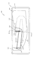
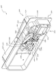
次いで図5から図23を参照して、第1可変入賞装置1000について説明する。図5は、遊技盤13の部分正面斜視図である。第1可変入賞装置1000は、その上面に備える傾斜面1237により、遊技者が右打ちを行うことで可変表時装置ユニット80の右方を流下する球の内、第2入球口640に入球せず、その下流へ流下した球のほぼ全てを流路形成部に案内する。
Next, the first
図6は、第1可変入賞装置1000の分解正面斜視図であり、図7は、第1可変入賞装置1000の分解背面斜視図である。第1可変入賞装置1000は、横長矩形の板形状から構成される本体部材1100と、その本体部材1100に正面側から締結固定される覆設前板1200と、それら本体部材1100と覆設前板1200との間に挟まれることで軸支される開閉板1300と、本体部材1100の背面側に回転可能に軸支され回転により開閉板1300に負荷を与える動力伝達部材1400と、その動力伝達部材1400を駆動する駆動装置1500と、開閉板1300と連動して球の排出を規制する規制部材1600と、本体部材1100に背面側から動力伝達部材1400、駆動装置1500及び規制部材1600を覆設するように締結固定される後カバー1700と、を主に備える。
FIG. 6 is an exploded front perspective view of the first
本体部材1100は、遊技盤の正面側に配置される横長矩形の薄板から形成される薄板部材1110と、その薄板部材1110に正面から背面側へ向けて凹設され開閉板1300の軸部1320を収容し部分的に貫通形成される収容部1120と、その収容部1120の正面視右側において検出センサ1240が嵌挿される貫通孔である保持孔1130と、薄板部材1110の正面側において球が流下する経路に合わせて突設される突設部1140と、薄板部材1110の正面から背面側へ球を排出する排出口1150と、薄板部材1110の背面側へ突設され動力伝達部材1400を支持する回転支持部1160と、排出口1150の上部において規制部材1600の軸部1610を支持可能に爪状に突設される支持爪部1170を、を主に備える。
The
収容部1120は、開閉板1300の軸部1320が収容される左右一対の支持凹部1121と、その支持凹部1121の間を繋ぐ直線の下方において矩形状に凹設される矩形凹部1122と、その矩形凹部1122の右端に沿って動作する開閉板1300の被荷重部1330を薄板部材1110の前後に移動させるために一対の支持凹部1121を繋ぐ直線と垂直な姿勢の矩形形状に貫通形成される貫通孔1123と、を主に備える。
The
支持凹部1121は、開閉板1300の軸部1320よりも幅が若干大きく形成され、組立状態において、開閉板1300の軸部1320が収容され、覆設前板1200の背面に凹設開口が閉鎖される。即ち、支持凹部1121と覆設前板1200の背面とで開閉板1300が軸支される。
The
矩形凹部1122は、開閉板1300の板部1310よりも表面積が大きくされ、その凹設深さは板部1310よりも若干深くされる。これにより、開閉板1300が傾倒する姿勢(閉状態)において、板部1310を完全に矩形凹部1122に収容でき、薄板部材1110の正面側に開閉板1300が張り出すことを防止できる。
The surface area of the
突設部1140は、覆設前板1200の貯留流路1231を流下する球に当接する位置まで突設される。流下する球は、突設部1140と当接することにより、減速される。なお、覆設前板1200の貯留流路1231にも、同様の突設部1235が、突設部1140と前後方向視で重ならない位置に配設される。
The projecting
回転支持部1160は、動力伝達部材1400を回転可能に軸支する軸部1161と、その軸部1161と同軸の円形状または円弧形状に沿って薄板部材1110の背面側へ均等な突設高さのリブ状に形成される円形リブ1162と、を主に備える。
The
円形リブ1162は、動力伝達部材1400の回転先端部1421と、薄板部材1110の背面との間隔を一定距離以上に維持する。即ち、動力伝達部材1400の動作中において、回転先端部1421と当接する全角度範囲において、円形リブ1162が形成される。
The
覆設前板1200は、本体部材1100の薄板部材1110から正面側に所定距離離れて配設される薄板部材1210と、その薄板部材1210の正面視左端部から背面側に延設される側壁部1220と、その側壁部1220の左右方向反対側において薄板部材1210の背面側へ向けて背面側に開口した箱状に延設される収容部1230と、その収容部1230の上端部に配設される検出センサ1240と、を主に備える。
The lining
薄板部材1210と、側壁部1220の正面視右側壁部と、収容部1230の正面視左側壁部と、本体部材1100の薄板部材1110とにより、球が上下方向に流下する孔である流路形成部が構成される。
The
収容部1230は、正面視コ字状に形成され、内部を球が流下可能な幅で形成される貯留流路1231と、その貯留流路1231の中腹部分において背面側へ向けて突設される突設部1235(図12参照)と、正面視右側の上面として形成される傾斜面1237と、を主に備える。
The
貯留流路1231は、背面側に開口する断面コ字状の側壁部が正面コ字状に折れ曲がりながら延設される態様で構成され、その開口が本体部材1100に塞がれることにより球が通過する流路を形成する。なお、本実施形態では、貯留流路1231の形成される領域の正面側部分にあたる薄板部材1210が光透過性の材料から形成される。従って、遊技者は、貯留流路1231を流下する球を視認可能とされる。
The
貯留流路1231は、最下端において球を背面側へ向けて案内する傾斜面である案内面1231a(図12参照)と、その案内面1231aに案内された球を前後方向に転動させる転動面1231bと、を主に備える。
The
転動面1231bの水平面に対する傾斜角度は、貯留流路1231の転動面1231bに到達する手前側(図12右側)部分の水平面に対する傾斜角度に比較して大きくされる。
The inclination angle of the rolling
突設部1235は、本体部材1100の突設部1140と略同一の構造を備える。即ち、突設部1235は、貯留流路1231を流下する球に当接可能な位置まで突設され、球と当接することにより球を減速させる。
The projecting
傾斜面1237は、正面視左方へ向かうほど下降傾斜する。これにより、傾斜面1237に着地した球を左方へ向けて転動させ、流路形成部へ案内することができる。
The
検出センサ1240は、第1特定入賞口1000aとしての貫通孔を備える。第1特定入賞口1000aを球が通過することにより、その通過を検出センサ1240が検出し、入賞個数のカウントが行われる。
The
開閉板1300は、姿勢の違いにより、球を検出センサ1240へ向けて転動させる場合と、球と当接せず下方へ落下させる場合とを切り替える部材であって、横長矩形状の板部1310と、その板部1310の短手方向端部から長手方向に沿って突設される一対の軸部1320と、正面視右側の軸部1320の根本において軸部1320と直角な平面に沿って延設される被荷重部1330と、を主に備える。
The opening /
板部1310は、上昇姿勢(開状態)において球が転動する転動面1311を備え、短手方向の長さが、短手方向を前後方向に沿わせる上昇姿勢(開状態)において覆設前板1200との間隔が球の半径以下となる長さとされ、長手方向の右端部が、検出センサ1240と近接する態様とされる。
The
また、板部1310は、軸部1320の反対側の端部の、上昇姿勢(開状態)における上側の角部に断面円弧形状に面取りされる面取り部1312を備える。
Further, the
板部1310は、左右方向に長尺に形成され、球を横並びで5個まで載置可能な長さとされる。
The
被荷重部1330は、転動面1311の正面側に延設される円弧形状の入球防止部1331と、転動面1311の背面側に延設される介在伝達部1332と、その介在伝達部1332から背面視右側(動力伝達部材1400が配設される側)に突設される係合部1333と、を主に備える。
The loaded
係合部1333は、動力伝達部材1400の動作軌跡に干渉する位置まで延設され、上面部に円弧形状に面取りされる面取り部1333aを備える。動力伝達部材1400との当接時には、角部ではなく面取り部1333aが動力伝達部材1400と当接するので、係合部1333と動力伝達部材1400との当接時における応力の集中を避けることができる。
The engaging
動力伝達部材1400は、円板形状の本体部1410と、その本体部1410から軸径方向に延設される延設部1420と、を主に備える。
The
本体部1410は、軸部1161が挿通される支持孔1411と、外周部付近から支持孔1411の穿設方向と平行に突設される突設ピン1412と、を主に備える。
The
突設ピン1412は、駆動装置1500の先端部材1520に係合する部分であり、駆動装置1500の励磁の切替により先端部材1520が直線動作することに伴い、突設ピン1412が変位し、動力伝達部材1400が回転動作する。
The
延設部1420は、延設先端部分に、支持孔1411の中心と同軸の円弧形状から形成される回転先端部1421と、その回転先端部1421から正面側に突設される押込部1422と、を備える。
The
駆動装置1500は、励磁の切替により可動部材を直線動作させるソレノイド1510と、そのソレノイド1510の可動部材の先端に配設される正面視H形状(上下にそれぞれ凹部を備える形状)の先端部材1520と、を主に備える。
The
先端部材1520は、その上側の凹部が、動力伝達部材1400の突設ピン1412を収容可能な形状で構成される。詳細には、動力伝達部材1400が回転動作する間中、突設ピン1412を内側に収容したままにする形状で凹部が形成される(図20参照)。
The
規制部材1600は、支持爪部1170に軸支される棒状の軸部1610と、その軸部1610の直径と同等の厚みで軸部1610の径方向に延設される延設部1620と、本体部材1100側の面が延設部1620と面位置で形成されると共に延設部1620よりも厚みの大きい球受け部1630と、を主に備える。
The regulating
延設部1620は、開閉板1300の介在伝達部1332の移動軌跡上に配置され、開閉板が上昇姿勢(開状態)となった時に介在伝達部1332から押圧負荷を受ける。
The
球受け部1630は、傾倒する姿勢(軸部1610の反対側の端部が下側位置に配置される姿勢、貯留状態)において、排出口1150と重なる態様(排出口1150の開口を球が排出されない程度に狭められる態様)で形成される。
The
なお、規制部材1600は、ねじりバネ(図示せず)により、上昇姿勢(軸部1610の反対側の端部が上側位置に配置される姿勢、排出状態)を維持する方向に付勢される。
The regulating
後カバー1700は、排出口1150から排出された球が通過する貫通孔である排出口1710を備える。排出口1710から排出された球は、図示しない球排出路へと案内される。
The
図8及び図9を参照して、開閉板1300の閉状態について説明する。図8は、第1可変入賞装置1000の正面図であり、図9は、図8のIX−IX線における第1可変入賞装置1000の断面図である。なお、図8及び図9では、開閉板1300が閉状態とされ、図8では、覆設前板1200の薄板部材1210が部分的に破られて図示される。
The closed state of the opening /
図8及び図9に示すように、開閉板1300が閉状態にされると、開閉板1300の板部1310が矩形凹部1122に収容されることにより、本体部材1100の薄板部材1110と、覆設前板1200の薄板部材1210との間の間隔を狭めることなく開閉板1300を本体部材1100の薄板部材1110に沿わせることができる。本体部材1100の薄板部材1110と、覆設前板1200の薄板部材1210とは、球が通過可能な間隔で並設されるので、図8及び図9に示す状態において、薄板部材1110,1210の間に球を案内することにより、流路形成部に沿って球を落下させることができる。
As shown in FIGS. 8 and 9, when the opening /
また、図9に示すように、開閉板1300が閉状態にされると、被荷重部1330の入球防止部1331が検出センサ1240の開口を部分的に覆う態様で本体部材1100の正面側に張り出す。そのため、球が検出センサ1240を通過することを物理的に防止することができ、イレギュラー入賞(例えば、開閉板1300に案内されずとも、釘などにぶつかった球が横方向に飛ばされ検出センサ1240を通過すること)を防止することができる。
Further, as shown in FIG. 9, when the opening /
なお、詳細は後述するが、開閉板1300の閉状態において、規制部材1600が排出状態となることから、貯留流路1231から球が排出される。そのため、図8では、貯留流路1231に球が貯留されていない状態を図示している。
Although the details will be described later, since the
図10及び図11を参照して、開閉板1300の開状態について説明する。図10は、第1可変入賞装置1000の正面図であり、図11は、図10のXI−XI線における第1可変入賞装置1000の断面図である。なお、図10及び図11では、開閉板1300が開状態とされ、図10では、覆設前板1200の薄板部材1210が部分的に破られて図示される。また、図11では、球の大きさを把握するために球の外形が想像線で図示される。
The open state of the opening /
図10及び図11に示すように、開閉板1300が開状態にされると、開閉板1300の板部1310が正面側に張り出し、板部1310と薄板部材1210との間隔が球の直径未満とされることにより、本体部材1100の薄板部材1110と、覆設前板1200の薄板部材1210との間に案内された球が落下することが防止される。
As shown in FIGS. 10 and 11, when the opening /
本体部材1100の薄板部材1110と、覆設前板1200の薄板部材1210との間に案内された球は開閉板1300の転動面1311を傾斜に沿って転動し、その右端から検出センサ1240を通過して貯留流路1231へ入球する。
The ball guided between the
なお、開閉板1300の開状態において、板部1310と覆設前板1200との間には球の半径よりも短い隙間が空けられる。従って、板部1310が覆設前板1200と当接する程度にまで延設される場合に比較して、必要な材料を少なくでき、開閉板1300に必要な材料費用を削減することができる。
In the open state of the opening /
また、開閉板1300の短手方向の先端の移動軌跡を小径化することにより、開閉板1300の回転時に開閉板1300の正面を通過する球と開閉板1300とが干渉することを回避し易くすることができる。
Further, by reducing the diameter of the movement locus of the tip of the opening /
ここで、詳細は後述するが、開閉板1300の開状態において、規制部材1600が貯留状態となることから、貯留流路1231から球は排出されず、検出センサ1240を通過した球が貯留流路に貯留される。そのため、図10では、貯留流路1231に球が貯留された状態を図示している。
Here, although details will be described later, since the regulating
図10に示すように、本実施形態の貯留流路1231は、所定個数(本実施形態では10個)を上限として球を貯留可能な長さで形成される。貯留装置1231に10個の球が貯留される場合、10個目の球は検出センサ1240に検出される位置で停止する。
As shown in FIG. 10, the
そのため、10個目の球が栓となり、11個目の球が検出センサ1240を通過することが防止される。換言すれば、11個目の球が検出センサ1240を通過しようとする場合の抵抗が極端に大きくなり、11個目の球が検出センサ1240に入り難い状態にすることができる。
Therefore, the tenth ball becomes a plug, and the eleventh ball is prevented from passing through the
本実施形態では、10個目の球が検出センサ1240に検出されたことを契機に開閉板1300が閉状態に切り替えられることで開閉板1300上に残っていた球は開閉板1300の下方へ流下し、開閉板1300の動作に伴い規制部材1600が排出状態に切り替えられることで貯留流路1231に貯留された球が排出される。
In the present embodiment, when the 10th ball is detected by the
ここで、図10に示すように、貯留流路1231から球が排出されていない状態において、10個目の球は検出センサ1240に検出されつつも、検出センサ1240を通過しきらない位置で停留する。
Here, as shown in FIG. 10, in a state where the spheres are not discharged from the
10個目の球が検出センサ1240に検出されると、開閉板1300が閉状態に切り替えられるが、その切り替えの途中で入球防止部1331からの負荷を受けながら10個目の球が貯留流路1231の内部へ押し込まれる(図21(b)参照)。即ち、開閉板1300が開状態の場合は10個目の球が検出センサ1240の開口を塞ぐ態様で停留し、開閉板1300が閉状態へ切り替わる途中においては、入球防止部1331が10個目の球と当接しながら(擦れながら)検出センサ1240の開口を塞ぐので、10個目の球が検出センサ1240を通過しきるタイミングと入球防止部1331が動作するタイミングとがずれることに起因して検出センサ1240の開口が開放される瞬間が生じることを防止でき、11球目の球が第1特定入賞口1000aを通過することを防止することができる。
When the 10th ball is detected by the
従って、規定個数目の球が検出センサ1240に検出されてから開閉板1300を閉状態へ変化させるまでの期間に制限を設ける必要が無く、任意に設定することができる。例えば、検出から0.2msecで開閉動作を開始しても良いし、検出から1秒後に開閉動作を開始しても良い。なお、本実施形態では、10個目の球が9個目の球に当接するまで待ってから(球の中心が入球防止部1331の正面側を越えて検出センサ1240側に配置されてから)開閉板1300を動作させるために、検出センサ1240に検出されてから0.5秒後に開閉板1300が開閉動作するように制御される。
Therefore, it is not necessary to set a limit on the period from the detection of the specified number of spheres by the
上述した開閉板1300の動作態様により、本実施形態では、開閉板1300が開状態を形成する間に、検出センサ1240を通過する球の個数を10個に制限することができる。なお、本実施形態では、球の入球の防止(遅延)を、11球目の球に対してのみ行うことができる。即ち、1球目から10球目の球においては、検出センサ1240を高速で通過することが可能である。これは、全球において球の通過を遅延させる場合に比較して、特別遊技状態の進行速度を増加させることにつながる。
According to the operation mode of the opening /
例えば、検出センサ1240を通過した球を、その通過位置で一度減速させることにより、後続の球の入賞を遅延させる構造の場合、11個目の球の入賞を抑制し易い一方で、1球目から10球目の球のそれぞれが、部分的に連なって転動面1311上を転動する際にも球を減速させてしまうので、検出センサ1240を10球目の球が通過するまでの時間が長くなり、遊技が間延びするという問題点があった。
For example, in the case of a structure in which a ball that has passed the
一方で、本実施形態では、1球目から10球目を減速させる構成は採用しておらず、11球目のみを検出センサ1240に入球させない構成なので、1球目から10球目は、例え球同士が連なって流下したとしても、その流下速度のまま検出センサ1240を通過させることができるので、遊技の高速化を図ることができる。
On the other hand, in the present embodiment, the configuration for decelerating the 1st to 10th balls is not adopted, and only the 11th ball is not allowed to enter the
また、球詰まりなどの修理により開閉板1300が開状態となる期間の大部分が経過してしまい、その期間の終わりがけに遊技を開始した場合においても、検出センサ1240に入球する球を無意味に減速させることは無いので、より多くの球を入球させることができる。
In addition, even if most of the period during which the opening /
また、11球目の球に関しては、どれほど高速で(開閉板1300が傾倒動作開始する前に検出センサ1240に到達し得る速度で)検出センサ1240に向かって流下したとしても、その速度に関わらず、11球目の球が検出センサ1240を通過することを10球目までの球により物理的に防止することができる。
Further, regarding the eleventh ball, no matter how fast (at a speed at which the opening /
図12を参照して、貯留流路1231に滞留する球の配置について説明する。図12は、図10のXII−XII線における第1可変入賞装置1000の断面図である。なお、図12では、貯留流路1231に貯留する球が図示される。
The arrangement of the spheres staying in the
ここで、貯留流路1231に貯留される球が毎回同じ配置となるメカニズムについて説明する。まず、空の状態の貯留流路1231に始めに入球した球P1は、貯留流路1231の最下部において後方傾斜する案内面1231aに案内され、規制部材1600の正面に当接する位置に配置される。
Here, a mechanism will be described in which the spheres stored in the
球P1は、それに続いて入球した球P2が下端部に到達することにより重みがかけられ、図12に図示される配置に落ち着く。球P2は、球P1の正面視右方(図12右方)において、前後方向に配置の自由度を持つ。即ち、パチンコ機10を配置した際の前後方向の倒れ具合より、覆設前板1200側に寄る場合もあるし、本体部材1100の突設部1140に寄る場合もある。なお、図12に図示される通り、突設部1140の突設先端が球P2に当接する位置に突設部1140が配設されるので、球P1に当接した状態において球P2が本体部材1100の薄板部材1110に当接することは無い。
The sphere P1 is weighted by the subsequent sphere P2 reaching the lower end, and settles in the arrangement shown in FIG. The sphere P2 has a degree of freedom in arrangement in the front-rear direction on the right side of the sphere P1 when viewed from the front (right side in FIG. 12). That is, depending on the degree of tilting in the front-rear direction when the
球P2は、それに続いて入球した球P3が球P2に当接する位置に到達することにより、重みがかけられる。ここで、本実施形態では、覆設前板1200に配置される突設部1235が、球P2が前後方向のいかなる位置にある場合であっても、その右方において球P2と突設部1235との間に球P3が入り込み覆設前板1200の薄板部材1210に当接することは不可能な位置(球P2との隙間を小さく維持する位置)に配設される。
The sphere P2 is weighted by reaching a position where the subsequently entered sphere P3 abuts on the sphere P2. Here, in the present embodiment, the projecting
そのため、球P2が前後方向のいかなる位置にあっても、球P3の中心位置は、球P2の中心位置の背面側に配置されることになり、球P3は球P2に背面側(図12上側)から当接することになる。従って、球P3の負荷により球P2が正面側(図12下側)へ寄せられる。これにより、球P2が図12に図示される配置に落ち着く。 Therefore, regardless of the position of the sphere P2 in the front-rear direction, the center position of the sphere P3 is arranged on the back side of the center position of the sphere P2, and the sphere P3 is on the back side of the sphere P2 (upper side of FIG. 12). ) Will come into contact. Therefore, the load of the sphere P3 causes the sphere P2 to move toward the front side (lower side in FIG. 12). As a result, the sphere P2 settles in the arrangement shown in FIG.
以降、球P3は続いて入球する球P4から、球P2が球P3から負荷を受けた条件とほぼ(前後方向が逆転することを除いて)同様の条件により負荷を受けることで、球P3が図12に図示される配置に落ち着く。 After that, the sphere P3 is loaded from the subsequently entering sphere P4 under almost the same conditions as the sphere P2 is loaded from the sphere P3 (except that the front-back direction is reversed), so that the sphere P3 is loaded. Settles in the arrangement illustrated in FIG.
即ち、貯留流路1231にn個目に入球した球の配置は、(n+1)個目に入球した球から前後方向へ向けた負荷を受けることにより一義的な位置に固定される。また、本実施形態では、球の配置の固定を貯留流路1231を狭めることによってではなく、貯留流路1231の断面積を球の直径よりも大きく維持しつつ、所定箇所に突設部1140,1235を配設することにより実現している。これにより、球詰まりの発生を防止しつつ、貯留された球の配置を一義的な位置に固定することができる。
That is, the arrangement of the nth ball entering the
上述したように、本実施形態では、突設部1140,1235を適切な位置に配置することにより、貯留流路1231に球を貯留する行為が起きる度に、固定された配置で球を貯留することができる。そのため、毎回の貯留個数を統一することができる。
As described above, in the present embodiment, by arranging the projecting
図13を参照して、貯留流路1231からの球の排出について説明する。図13(a)及び図13(b)は、図10のXII−XII線における第1可変入賞装置1000の断面図である。なお、図13(a)では、球P1が排出され球P2が転動面1231bに乗った状態が、図13(b)では、球P2が排出され、球P3が図12における球P2の位置に配置された状態が図示される。
With reference to FIG. 13, the discharge of the sphere from the
後述するように、ソレノイド1510の励磁が解除され、開閉板1300が閉状態とされることに伴い、規制部材1600が排出状態となり貯留流路1231から球が排出される。球の排出時には。最下端に配置された球(図12における球P1)が転動面1231bの傾斜に沿って背面側へ排出され、それによりできた空間に、続く球(図12における球P2)が流れ込む態様で球が順に排出される。
As will be described later, when the excitation of the
ここで、転動面1231bの水平面に対する傾斜角度の方が、貯留流路1231の延設部分(左右方向へ延びる流路)の水平面に対する傾斜角度に比較して大きいので、球P1の流下速度の方が球P2の流下速度よりも大きくなることから、球P1と球P2との間に隙間が生じる(図13(a)参照)。従って、球P1の排出時に球P2から球P1へ与えられる負荷を最小限に抑えることができるので、球P1の後続に貯留される球の個数に寄らず、球P1の排出時の速度を均一化することができる。
Here, since the inclination angle of the rolling
球P1が排出された後、後続の球P2,P3,P4は、貯留流路1231の延設部分の傾斜に沿って下流側(図12左側)へ流下する。ここで球P2はスムーズに案内面1231aまで到達し転動面1231bに乗る一方、球P3,P4は、流下の過程において突設部1140,1235に当接する(図13(a)参照)。この当接により、球P3,P4は、前後方向成分を持つ方向DP3,DP4に向け変えられ、それぞれ先導される球P2,P3の位置を経由すると共に、減速する。
After the sphere P1 is discharged, the subsequent spheres P2, P3, and P4 flow down to the downstream side (left side in FIG. 12) along the inclination of the extended portion of the
換言すれば、球P3,P4は、突設部1140,1235に当接することにより、貯留流路1231の延設方向と直交する方向に配置替えされると共に、先に貯留された球が停留していた位置に配置替えされ、減速する。
In other words, the spheres P3 and P4 are rearranged in the direction orthogonal to the extension direction of the
これにより、球P2と球P3との間に隙間が生じることになり(図13(b)参照)、球P2の排出時に球P3から球P2へ与えられる負荷を最小限に抑えることができるので、球P2の後続に貯留される球の個数に寄らず、球P2の排出時の速度を均一化することができる。 As a result, a gap is created between the sphere P2 and the sphere P3 (see FIG. 13B), and the load applied from the sphere P3 to the sphere P2 when the sphere P2 is ejected can be minimized. , The speed at the time of discharging the sphere P2 can be made uniform regardless of the number of spheres stored after the sphere P2.
即ち、後続の球ほど貯留流路1231を長い距離流下するので、貯留球数が多くなるほど後続の球の重力による加速の仕方に変化が生じ、それに伴い球P2の排出態様(排出時の速度、球P1との間の排出間隔など)が変化する恐れがあるが、その排出態様の変化を、上述した突設部1140,1235の作用(転動面1231bに乗り排出される球と、その後続の球との間に隙間を空け、重力による負荷を解消する作用)により抑制することができる。
That is, since the subsequent spheres flow down the
以降は、後続の球が繰り返し図13(a)に示す配置から図13(b)に示す配置への流下を繰り返すことで、貯留流路1231からの球の排出が行われる。上述したように、転動面1231bを転動して排出される球と、その後続の球との間に隙間を生じさせることにより、排出される球が後続の球の重みを受けずに排出されるので、貯留流路1231に貯留される球の個数に寄らず、球の排出態様(排出時の速度、排出間隔など)を均一化することができる。
After that, the subsequent spheres repeatedly flow down from the arrangement shown in FIG. 13A to the arrangement shown in FIG. 13B, so that the spheres are discharged from the
換言すれば、本実施形態では、突設部1140,1235により、球の排出態様(排出時の速度、排出間隔など)を均一化することができる。なお、球の排出態様は、本実施形態では、球が1個排出されるのに約0.2秒間を要する態様とされる。従って、規制部材1600を2秒間以上、排出状態で維持することにより、貯留流路1231に貯留可能な最大個数(10個)の球を全て排出することができる。
In other words, in the present embodiment, the projecting
図14は、第1可変入賞装置1000の背面斜視図であり、図15は、第1可変入賞装置1000の背面図であり、図16は、図15のXVI−XVI線における第1可変入賞装置1000の断面図である。なお、図14から図16では、開閉板1300の閉状態が図示されると共に、後カバー1700の図示が省略される。
14 is a rear perspective view of the first
図14及び図15に示すように、開閉板1300が閉状態のとき、ソレノイド1510は非励磁の状態であり、動力伝達部材1400の回転先端部1421が開閉板1300の係合部1333の上方に離間して配置される。
As shown in FIGS. 14 and 15, when the opening /
開閉板1300の介在伝達部1332が上側に配置され規制部材1600と離間されるので、規制部材1600が介在伝達部1332から負荷を受けることは無く、規制部材1600がねじりバネ(図示せず)の付勢力により排出状態で維持される。
Since the intervening
また、図16に示すように、開閉板1300の閉状態において、入球防止部1331が、検出センサ1240の開口の大きさを球の投影面積以下とする態様で張り出す。これにより、球が検出センサ1240を通過することを物理的に防止することができる。
Further, as shown in FIG. 16, in the closed state of the opening /
図17は、第1可変入賞装置1000の背面斜視図であり、図18は、第1可変入賞装置1000の背面図であり、図19は、図18のXIX−XIX線における第1可変入賞装置1000の断面図である。なお、図17から図19では、開閉板1300の開状態が図示されると共に、後カバー1700の図示が省略される。
17 is a rear perspective view of the first
図17及び図18に示すように、開閉板1300が開状態のとき、ソレノイド1510は励磁された状態であり、動力伝達部材1400の回転先端部1421が反時計回りに変位し、開閉板1300の係合部1333が押込部1422に押し込まれる。
As shown in FIGS. 17 and 18, when the opening /
開閉板1300の介在伝達部1332は動力伝達部材1400の回転に伴って下側に配置され、この状態において規制部材1600の延設部1620が介在伝達部1332から負荷を受け、規制部材1600の姿勢が傾倒する姿勢に切り替えられる(規制部材1600が貯留状態に切り替えられる)。
The intervening
開閉板1300の開状態において、規制部材1600には、ソレノイド1510の駆動力に伴う負荷と、ねじりバネ(図示せず)の付勢力とが与えられるが、本実施形態では、ねじりバネの付勢力を大きく維持しながら、開閉板1300を開状態で維持する際のソレノイド1510の駆動力を抑制可能な構造を採用している。ねじりバネの付勢力が大きいことは、規制部材1600を排出状態に即座に切り替え可能にし、それにより貯留流路1231からの球の排出を迅速に行うことが可能となるという効果につながる。以下、採用した構造について説明する。
In the open state of the opening /
本実施形態では、開閉板1300の係合部1333は、開閉板1300が閉状態から動作開始する際には動力伝達部材1400の動作軌跡E1上に配置される一方で、開閉板1300が開状態に切り替わると、動力伝達部材1400の回転軸方向に沿って動作軌跡E1の外方へ押しやられる。なお、動作軌跡E1は、押込部1422(図6参照)を含む部分の移動軌跡の外形として図示される。
In the present embodiment, the engaging
従って、開閉板1300が開状態に切り替えられた後で開閉板1300から動力伝達部材1400に伝達される負荷は、動力伝達部材1400の動作方向(回転方向)では無く、その回転方向を形成する面と垂直方向である軸方向にかけられる。そのため、開閉板1300にかけられる軸部1320回りの負荷が動力伝達部材1400を介してソレノイド1510に伝達されることを防止することができる。
Therefore, the load transmitted from the opening /
即ち、規制部材1600を付勢するねじりバネ(図示せず)の付勢力は、開閉板1300を閉状態へ向けて押し戻す方向に向くが、付勢力がどれだけ大きくても、この付勢力が動力伝達部材1400を介してソレノイド1510にかけられることは無い。
That is, the urging force of the torsion spring (not shown) that urges the regulating
これにより、開閉板1300を一度開状態に切り替えてしまえば、開閉板1300を開状態で維持するためのソレノイド1510の駆動力が開閉板1300にかけられる負荷により変動することを防止することができる。従って、ソレノイド1510に印加する電圧を開閉板1300に最大値でかけ続けることを不要とできる。
As a result, once the opening /
即ち、動作開始時にねじりバネ(図示せず)の付勢力に抗して規制部材1600を貯留状態に切り替えられる程度の駆動力が生じるようにソレノイド1510を励磁した後は、印加電圧を低下させたとしても、開閉板1300を開状態で維持することができる。
That is, after exciting the
従って、開閉板1300及び規制部材1600に変動する負荷がかけられたとしても、その負荷に影響されず、開閉板1300を開状態に維持すると共に規制部材1600を貯留状態に維持することができる。
Therefore, even if a fluctuating load is applied to the opening /
なお、開閉板1300及び規制部材1600にかけられる変動する負荷としては、球の重みにより与えられる負荷が例示される。即ち、例えば、開閉板1300は、転動面1311に球が着地する構成であるので、球が着地した際に球の重みによる負荷を受けるし、その球の数はたびたび変化するので、開閉板1300には変動する負荷が与えられる。また、例えば、規制部材1600には、貯留流路1231に貯留される球、特に貯留流路1231の最下端部に配置された球から負荷が与えられるので、その球がある場合と、無い場合とで、変動する負荷が与えられる。
As the fluctuating load applied to the opening /
なお、図14から図19で上述したように、開閉板1300と規制部材1600とは連動するので、開閉板1300の開状態を維持したまま、規制部材1600を排出状態とすることはできない。そのため、開閉板1300を不正に開状態で維持したままとしても、貯留流路1231に貯まり得る以上の球(本実施形態では10球以上の球)が検出センサ1240を通過することを物理的に防止できる。これにより、開閉板1300を開状態で不正に維持し、獲得する賞球を多くする不正を防止することができる。
As described above in FIGS. 14 to 19, since the opening /
図20及び図21は、開閉板1300及び規制部材1600の動作が時系列に沿って図示される。図20(a)は、第1可変入賞装置1000の背面図であり、図20(b)は、図20(a)のXXb−XXb線における第1可変入賞装置1000の断面図であり、図20(c)は、第1可変入賞装置1000の背面図であり、図21(a)は、第1可変入賞装置1000の背面図であり、図21(b)は、図21(a)のXXIb−XXIb線における第1可変入賞装置1000の断面図であり、図21(c)は、第1可変入賞装置1000の背面図であり、図21(d)は、図21(c)のXXId−XXId線における第1可変入賞装置1000の断面図である。
20 and 21 show the operation of the opening /
なお、図20及び図21では、理解を容易とするために、開閉板1300、動力伝達部材1400、駆動装置1500の先端部材1520及び規制部材1600のみが組立状態(図5参照)の配置を維持して図示され、その他の構成の図示が省略されると共に、開閉板1300が開状態から閉状態へ向けて状態変化する様子が時系列で図示される。
In FIGS. 20 and 21, only the opening /
即ち、図20(a)及び図20(b)では、駆動装置1500の先端部材1520が基準線O1から第1距離h1だけ離間する位置に配置された状態(ソレノイド1510が非励磁の状態)が、図20(c)では、先端部材1520が変位し基準線O1から第1距離h1よりも短い第2距離h2だけ離間する位置に配置された状態が、図21(a)及び図21(b)では、先端部材1520が変位し基準線O1から第2距離h2よりも短い第3距離h3だけ離間する位置に配置された状態が、図21(c)及び図21(d)では、先端部材1520が変位し基準線O1から第3距離h3よりも短い第4距離h4だけ離間する位置(ソレノイド1510が励磁された場合の最終到達位置)に配置された状態が、それぞれ図示される。
That is, in FIGS. 20A and 20B, the state in which the
なお、図21(b)では手前側に配置される第1特定入賞口1000aが参考として想像線で図示されると共に、図示に用いた断面と同一断面における球の断面形状の外形が想像線で図示される。即ち、図10に示す状態において、開閉板1300は球に干渉することなく図21(b)に示す状態まで回転動作することができる。
In FIG. 21B, the first specific winning
図20(a)に示す状態から図20(c)に示す状態まででは、動力伝達部材1400は回転動作するものの、開閉板1300はそのままの姿勢を維持する。なお、図20(c)において、動力伝達部材1400の回転先端部1421と開閉板1300の係合部1333とが当接する。
From the state shown in FIG. 20A to the state shown in FIG. 20C, the
これにより、開閉板1300を閉状態から開状態へ動作させる前に、動力伝達部材1400に勢いを付けることができるので、動力伝達部材1400の回転開始と同時に開閉板1300を回転開始させる場合に比較して、回転開始時(初動時)に必要となる駆動力を低減できると共に、開閉板1300の動作速度を上昇させることができる。
As a result, the
図20(c)に示す状態から、図21(a)に示す状態まででは、規制部材1600は排出状態を維持する一方で、開閉板1300は閉状態から動作し、閉状態と開状態との間の中間状態とされる(図21(b)参照)。
From the state shown in FIG. 20 (c) to the state shown in FIG. 21 (a), the regulating
図21(b)に示す開閉板1300の中間状態において、板部1310が正面側に張り出されることにより、球が開閉板1300の正面側(図21(b)右側)に流下した場合には、板部1310の転動面1311で球を受け止めることができる。この場合、球の重みは転動面1311を押し下げる方向(図21(b)時計回り)に作用するが、先端部材1520が背面視右向き(図21(a)右向き)に移動することにより動力伝達部材1400を介して係合部1333に反対方向(図21(b)反時計回り)の負荷が与えられるので、球の重みで開閉板1310が回転することを防止することができる。
In the intermediate state of the opening /
従って、図21(b)に示す開閉板1300の中間状態では、排出口1150からの球の排出を可能としながら、開閉板1300の正面側を球が下方へ通過することを抑制することができる。
Therefore, in the intermediate state of the opening /
これにより、貯留流路1231からの球の排出にかかる時間中は規制部材1600を排出状態に維持するという課題と、それと相反する開閉板1300の閉状態を短縮する(インターバルを短縮する)という課題とを、図21(a)に示す状態において、球の排出は持続させながら、板部1310を途中位置まで張り出させ転動面1311と覆設前板1200との間で球を挟むことにより、共に達成することができる。
As a result, there is a problem of maintaining the regulating
同時に、図21(b)に示す状態において、開閉板1300は球の下方への通過を防止しつつ、検出センサ1240への入球は防止する姿勢とされる。即ち、図21(b)に示す状態では、転動面1311が、検出センサ1240の開口の底面よりも下方に離間した位置とされるので、図21(b)に示す状態において転動面1311に乗った球が、そのまま検出センサ1240を通過することを防止することができる。これにより、規制部材1600が排出状態である場合に検出センサ1240を球が通過することを防止でき、第1可変入賞装置1000により球の入賞個数を制限するという機能を有効に維持することができる。
At the same time, in the state shown in FIG. 21B, the opening /
なお、図21(d)に示すように、開閉板1300が開状態に切り替わると同時に、規制部材1600が貯留状態に切り替えられる。また、図20及び図21で図示するように、駆動装置1500の先端部材1520の動作により、開閉板1300と規制部材1600とが連動する。即ち、駆動装置1500のソレノイド1510(図6参照)の駆動力を、開閉板1300と規制部材1600との駆動力に兼用することができる。
As shown in FIG. 21D, at the same time that the opening /
図20及び図21では、開閉板1300が閉状態から開状態へ切り替えられる場合を説明したが、開閉板1300が開状態から閉状態へ切り替えられる場合は、図20及び図21を遡ることにより把握することができる。
20 and 21 have described the case where the opening /
開状態から閉状態へ切り替えられる場合、始めに、図21(d)に示す状態から、図21(b)に示す状態に変化する。ここで、規制部材1600の動作方向には、開閉板1300の被荷重部1330が配置されるので、被荷重部1330の移動量以上に規制部材1600が移動することは無い。
When switching from the open state to the closed state, first, the state shown in FIG. 21 (d) is changed to the state shown in FIG. 21 (b). Here, since the loaded
即ち、開閉板1300が動作してから規制部材1600が排出状態に切り替えられるので、規制部材1600が排出状態に切り替えられた後で、開閉板1300が開状態を維持することを不可能とすることができる。これにより、例えば、球が排出され始めてから、その若干後のタイミングで球が検出センサ1240を通過するというイレギュラーな入賞が生じることを防止することができる。
That is, since the
また、図21(b)に示す状態において、依然として検出センサ1240の開口が開放され、転動面1311に球が当接し跳ねさえすれば、検出センサ1240に球が入球し得るように思えるが、本実施形態では、それを不可能とすることができる。
Further, in the state shown in FIG. 21B, it seems that the ball can enter the
即ち、図21(b)に示す状態を、開閉板1300を開状態から閉状態とする途中の状態として見る場合、動力伝達部材1400の回転先端部1421は上昇動作するので、転動面1311に球が当接する際に、その球の重さ方向の反対方向に働く開閉板1300を支える負荷が発生しない。従って、球が転動面1311に当接すると、球の重みで板部1310が下降動作するので、球を検出センサ1240まで跳ねさせることができない。これにより、イレギュラーな入賞が生じることを防止することができる。
That is, when the state shown in FIG. 21B is viewed as a state in which the opening /
図22を参照して、ROM202(図4参照)の内容について説明する。図22(a)は、主制御装置110内のROM202の電気的構成を示すブロック図であり、図22(b)は、第1当たり種別カウンタC2と特別図柄における大当たり種別との対応関係を模式的に示した模式図であり、図22(c)は、第2当たり乱数カウンタC4と普通図柄における当たりとの対応関係を模式的に示した模式図である。
The contents of ROM 202 (see FIG. 4) will be described with reference to FIG. FIG. 22A is a block diagram showing the electrical configuration of the
図22(a)に示すように、主制御装置110のROM202には、上記した固定値データの一部として、第1当たり乱数テーブル202a、第1当たり種別選択テーブル202b、第2当たり乱数テーブル202c、および変動パターン選択テーブル202dが少なくとも記憶されている。
As shown in FIG. 22A, the
第1当たり乱数テーブル202aは、定期的(例えば、2msecごと)に更新される第1当たり乱数カウンタの大当たり判定値が記憶されているデータテーブルである。始動入賞に基づいて取得した第1当たり乱数カウンタの値が、第1当たり乱数テーブル202aに規定されているいずれかの判定値と一致した場合に、特別図柄の大当たりであると判別される。 The first hit random number table 202a is a data table in which the jackpot determination value of the first hit random number counter, which is updated periodically (for example, every 2 msec), is stored. When the value of the first random number counter acquired based on the starting prize matches any of the determination values defined in the first random number table 202a, it is determined that the special symbol is a big hit.
第1当たり種別選択テーブル202b(図22(b)参照)は、大当たり種別を決定するための判定値が記憶されているデータテーブルであり、第1当たり種別カウンタC2の判定値が、各大当たり種別、および特別図柄の抽選契機となった入球口の種別に対応付けて規定されている。本実施形態のパチンコ機10では特別図柄の大当たりと判定された場合に、始動入賞に基づいて取得した第1当たり種別カウンタC2の値と、第1当たり種別選択テーブル202bとが比較され、第1当たり種別カウンタC2の値に対応する大当たり種別が選択される。
The first hit type selection table 202b (see FIG. 22B) is a data table in which judgment values for determining the jackpot type are stored, and the judgment value of the first hit type counter C2 is each jackpot type. , And the type of entrance that triggered the lottery of special symbols. In the
具体的には、特別図柄1の抽選(第1入球口64への入球に基づく抽選)で大当たりとなった場合には、第1当たり種別カウンタC2の値が「0〜19」の範囲には、大当たりAが対応付けられて規定されている(図22(b)の202b1参照)。
Specifically, when a big hit is obtained in the
大当たりAとなった場合は、15ラウンドの大当たり遊技が、第1可変入賞装置1000の第1の作動パターンで実行される。この場合、遊技者は、約2250個の賞球の払い出しを受けることができる。
When the jackpot A is obtained, the jackpot game of 15 rounds is executed in the first operation pattern of the first
第1当たり種別カウンタC2の値が「20〜49」の範囲には、大当たりBが対応付けられて規定されている(図22(b)の202b2参照)。 The jackpot B is associated with the range in which the value of the first hit type counter C2 is "20 to 49" (see 202b2 in FIG. 22B).
大当たりBとなった場合は、8ラウンドの大当たり遊技が、第1可変入賞装置1000の第1の作動パターンで実行される。この場合、遊技者は、約1200個の賞球の払い出しを受けることができる。
When the jackpot B is obtained, the jackpot game of 8 rounds is executed in the first operation pattern of the first
第1当たり種別カウンタC2の値が「50〜99」の範囲には、大当たりCが対応付けられて規定されている(図22(b)の202b3参照)。 The jackpot C is associated with the range in which the value of the first hit type counter C2 is "50 to 99" (see 202b3 in FIG. 22B).
大当たりCとなった場合は、4ラウンドの大当たり遊技が、第1可変入賞装置1000の第1の作動パターンで実行される。この場合、遊技者は、約600個の賞球の払い出しを受けることができる。
When the jackpot C is obtained, the jackpot game of four rounds is executed in the first operation pattern of the first
上述したように、特別図柄1の抽選(第1入球口64への入球に基づく抽選)で大当たりとなると、いずれの場合であっても、第1可変入賞装置1000は第1の作動パターンで動作する。従って、遊技者が獲得できる賞球の払い出し個数の差はラウンド数による差として表れ、ラウンド数が多くなるほど、払い出しの賞球個数が多くなると共に、大当たり遊技にかかる時間も多くなる。
As described above, when a big hit is obtained in the lottery of the special symbol 1 (lottery based on the entry into the first entry ball 64), the first
特別図柄1の抽選(第1入球口64への入球に基づく抽選)に基づく大当たりでは、20%の確率で15ラウンドの大当たりを獲得できる一方、50%の確率で4ラウンドの大当たりとなるので、基本的には、大量の賞球を期待することはできない。一方で、4ラウンドの大当たり遊技は、15ラウンドの大当たり遊技に比較して短時間で終了するので、その後の大当たりの獲得を狙うための球の打ち出しを、早期に開始することができる。
In the jackpot based on the
一方、特別図柄2の抽選(第2入球口640への入球に基づく抽選)で大当たりとなった場合には、第1当たり種別カウンタC2の値が「0〜79」の範囲には、大当たりaが対応付けられて規定されている(図22(b)の202b4参照)。
On the other hand, in the case of a big hit in the
大当たりaとなった場合は、大当たりAの時と同様に、15ラウンドの大当たり遊技が、第1可変入賞装置1000の第1の作動パターンで実行される。この場合、遊技者は、約2250個の賞球の払い出しを受けることができる。
When the jackpot a is reached, a 15-round jackpot game is executed in the first operation pattern of the first
第1当たり種別カウンタC2の値が「80〜89」の範囲には、大当たりbが対応付けられて規定されている(図22(b)の202b5参照)。 In the range where the value of the first hit type counter C2 is "80 to 89", the jackpot b is associated and defined (see 202b5 in FIG. 22B).
大当たりbとなった場合は、15ラウンドの大当たり遊技が、第1可変入賞装置1000の第2の作動パターン(詳細は後述する)で実行される。この場合、遊技者に払い出される賞球は、必然的に2250個未満(本実施形態では1200個)とされ、更に、大当たり遊技にかかる時間が大当たりaの場合を越える。
When the jackpot b is reached, the jackpot game of 15 rounds is executed in the second operation pattern (details will be described later) of the first
第1当たり種別カウンタC2の値が「90〜99」の範囲には、大当たりcが対応付けられて規定されている(図22(b)の202b6参照)。 The jackpot c is associated with the range in which the value of the first hit type counter C2 is "90 to 99" (see 202b6 in FIG. 22B).
大当たりcとなった場合は、15ラウンドの大当たり遊技が、第1可変入賞装置1000の第3の作動パターン(詳細は後述する)で実行される。この場合、遊技者に払い出される賞球は、必然的に2250個未満(本実施形態では1875個)とされ、更に、大当たり遊技にかかる時間が大当たりaの場合を越え、ラウンドごとに払い出される賞球や大当たり遊技にかかる時間が変動する。
When the jackpot c is reached, the jackpot game of 15 rounds is executed in the third operation pattern (details will be described later) of the first
上述したように、特別図柄2の抽選(第2入球口640への入球に基づく抽選)で大当たりとなると、大当たり種別に応じて、第1可変入賞装置1000の作動パターンが変化する。この作動パターンの違いにより、大当たりラウンド数を不変とする一方で、払い出し個数に差を設けつつ、大当たり遊技に要する時間を変化させることができる。本実施形態では、払い出し個数が少ない場合(大当たりb及び大当たりc)の方が、払い出し個数の多い場合(大当たりa)に比較して、大当たり遊技に要する時間を長期化させることができる。即ち、払い出し個数が少ない大当たり(大当たりb及び大当たりc)を獲得した場合、次の大当たりを狙って球を打ち出すタイミングが、大当たりaの場合に比較して遅らされることになる。
As described above, when a big hit is obtained in the lottery of the special symbol 2 (lottery based on the entry of the ball into the second entrance 640), the operation pattern of the first
従って、賞球個数に差を設けることに加え、大当たり遊技に要する時間を強制的に長期化することにより、大当たり種別の違いによって大当たり遊技により遊技者が得られる単位時間あたりの利益(時間効率を含めた払い出し個数)に差を設けることができる。 Therefore, in addition to providing a difference in the number of prize balls, by forcibly prolonging the time required for the jackpot game, the profit per unit time (time efficiency) that the player can obtain by the jackpot game due to the difference in the jackpot type can be obtained. There can be a difference in the number of payouts including).
これにより、特別図柄2の抽選(第2入球口640への入球に基づく抽選)での大当たりの内訳に、時間効率よく多量の払い出しを受けられる大当たり(大当たりa)と、時間効率悪く払い出しも少ない大当たり(大当たりb、大当たりc)とを設ける事ができ、大当たりaを獲得した場合に得られる遊技者の利益を増大させることができる。これにより、大当たりaを獲得する確率を大きく維持しながら、所定時間継続して遊技をする場合の払い出し個数の差(獲得出球の総数の最大値と、獲得出球の総数の最小値との差)を大きくすることができる遊技機を構成することができる。
As a result, the breakdown of the jackpot in the
上述した通り、特別図柄の確変中は、普通図柄の当たり確率がアップし、普通図柄の変動時間が短くなり(3秒)、普通図柄の当たりとなった場合における電動役物640aの開放時間が長くなる(1秒×2回)ように設定される。よって、第2入球口640へと球を入球させやすくなるので、特別図柄2の抽選が行われやすくなる。従って、一旦特別図柄の確変状態へと移行させることができれば、特別図柄の大当たりとなりやすく、且つ、大当たりとなった場合に大当たりa(最大出球の大当たり)となりやすい特別図柄の確変状態が繰り返されやすくなるので、遊技者が多量の賞球を獲得し易くなる。これにより、遊技者に対して特別図柄の確変状態へと移行させることを強く期待させながら遊技を行わせることができるので、遊技者の遊技に対する興趣を向上させることができる。
As described above, during the probability change of the special symbol, the hit probability of the normal symbol is increased, the fluctuation time of the normal symbol is shortened (3 seconds), and the opening time of the
第2当たり乱数テーブル202c(図22(c)参照)は、普通図柄の当たり判定値が記憶されているデータテーブルである。具体的には、普通図柄の通常状態において、普通図柄の当たりとなる判定値として、「5〜28」が規定されている(図22(c)の202c1参照)。また、普通図柄の高確率状態において、普通図柄の当たりとなる判定値として、「5〜204」が規定されている(図22(c)の202c2参照)。本実施形態のパチンコ機10では、普通入球口67を球が通過することに基づいて取得される第2当たり乱数カウンタC4の値と、第2当たり乱数テーブル202cとを参照し、普通図柄の当たりであるか否かを判定している。変動パターン選択テーブル202dは、変動パターンの表示態様を決定するための変動種別カウンタの判定値が表示態様毎にそれぞれ規定されているデータテーブルである。
The second hit random number table 202c (see FIG. 22C) is a data table in which hit determination values of ordinary symbols are stored. Specifically, in the normal state of the normal symbol, "5-28" is defined as a determination value for hitting the normal symbol (see 202c1 in FIG. 22 (c)). Further, in the high probability state of the normal symbol, "5-204" is defined as a determination value for hitting the normal symbol (see 202c2 in FIG. 22 (c)). In the
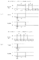
次いで、図23を参照して、本実施形態における第1特定入賞口1000aの開放パターンについて説明する。図23(a)は、第1の作動パターンにおける第1特定入賞口1000aの計時変化を示した図であり、図23(b)は、第2の作動パターンにおける第1特定入賞口1000aの計時変化を示した図であり、図23(c)は、第3の作動パターンにおける第1特定入賞口1000aの計時変化を示した図である。
Next, with reference to FIG. 23, the opening pattern of the first specific winning
MPU201(図4参照)は、前記特図当り決定において大当りを決定した場合には、特図変動表示(図柄変動演出)の終了後に、決定した種類の大当り遊技の制御を開始する。以下、大当り遊技が付与される場合に行われる開閉板1300の作動制御について説明する。
When the jackpot is determined in the special figure hit determination, the MPU 201 (see FIG. 4) starts controlling the determined type of jackpot game after the end of the special figure variation display (design variation effect). Hereinafter, the operation control of the opening /
<第1の作動パターンで動作する場合>
大当たり種別が、大当たりA、大当たりB、大当たりC又は大当たりaの大当たり遊技の場合には、前記第1の作動パターンに基づいて開閉板1300が動作するようMPU201がソレノイド1510を駆動制御する。MPU201は、特図変動表示(図柄変動演出)が終了すると、タイマ手段(図示せず)が所定のオープニング時間OP(10秒)が経過するまで開閉板1300を閉状態に保持するようソレノイド1510を駆動制御し、オープニング時間OPの経過後に、1ラウンド目のラウンド遊技Rを開始する。
<When operating with the first operation pattern>
When the jackpot type is jackpot A, jackpot B, jackpot C, or jackpot a jackpot game, the
すなわち、第1の作動時間T1(最大30秒)をタイマ手段で計測を開始すると共に開閉板1300を閉状態から開状態へ変位させて第1特定入賞口1000aを開放するようソレノイド1510を駆動制御して、開閉板1300に長時間動作を行わせる。
That is, the
そして、1ラウンド目のラウンド遊技Rにおいてラウンド終了条件(ラウンド遊技時間(第1の作動時間T1の最大値である30秒間)の経過または規定個数(本実施絵形態では10個)のパチンコ球の入賞)が満たされた場合に、開閉板1300を閉状態へ変位させて第1特定入賞口1000aを閉鎖するようソレノイド1510を駆動制御して、1ラウンド目のラウンド遊技Rが終了する。
Then, in the first round game R, the lapse of the round end condition (the round game time (30 seconds which is the maximum value of the first operating time T1) or the specified number (10 in the present embodiment) of the pachinko balls When the winning) is satisfied, the
1ラウンド目のラウンド遊技Rが終了すると、タイマ手段は、ラウンド間第1インターバル時間Int1(2.0秒)が経過するまで開閉板1300を閉状態に保持するようソレノイド1510を駆動制御し、ラウンド間第1インターバル時間Int1の経過後に、2ラウンド目のラウンド遊技Rを開始する。
When the round game R of the first round is completed, the timer means drives and controls the
ラウンド間第1インターバル時間Int1は、貯留流路1231に貯留可能な個数の球を全球排出可能な時間として設定される。即ち、上述したように、本実施形態では貯留流路1231に最大で10個の球が貯留され、その貯留個数によらず1個あたり約0.2秒の間隔で球を排出するように構成される。従って、10個の球を排出するには、調度2秒間必要となる。
The first interval time Int1 between rounds is set as a time during which the number of balls that can be stored in the
2ラウンド目では、1ラウンド目の開始と同様に、第1の作動時間T1(最大30秒)をタイマ手段で計測を開始すると共に開閉板1300を閉状態から開状態へ変位させて第1特定入賞口1000aを開放するようソレノイド1510を駆動制御して、開閉板1300に長時間動作を行わせる。
In the second round, as in the start of the first round, the first operation time T1 (maximum 30 seconds) is measured by the timer means, and the opening /
そして、2ラウンド目のラウンド遊技Rにおいてラウンド終了条件(ラウンド遊技時間(第1の作動時間T1の最大値である30秒間)の経過または規定個数のパチンコ球の入賞)が満たされた場合に、開閉板1300を閉状態へ変位させて第1特定入賞口1000aを閉鎖するようソレノイド1510を駆動制御して、2ラウンド目のラウンド遊技Rが終了する。
Then, when the round end condition (round game time (30 seconds, which is the maximum value of the first operating time T1) elapses or a specified number of pachinko balls are won) is satisfied in the second round game R. The
第1の作動パターンでは、ラウンド間第1インターバル時間Int1の球の排出により、各ラウンド目のラウンド遊技Rの開始時における貯留流路1231の内部に球が残留しない状態を形成することができる。従って、2ラウンド目以降も、規定個数(本実施形態においては、10個)のパチンコ球を第1特定入賞口1000aに通過させることができるので、各ラウンドの第1の作動時間T1の最大長さ(30秒)を待つことなくラウンド遊技Rを終了させることができる。従って、ラウンド遊技Rを迅速に進行させることができる。
In the first operation pattern, it is possible to form a state in which no balls remain inside the
以降は同様に、各ラウンド遊技Rの間にラウンド間第1インターバル時間Int1を挟んで3ラウンド目〜最大15ラウンド目のラウンド遊技Rが繰り返されて、開閉板1300が閉状態および開状態の間で変位し、第1特定入賞口1000aを開閉するようソレノイド1510が駆動制御される。
After that, similarly, the round game R from the third round to the maximum 15 rounds is repeated with the first interval time Int1 between rounds sandwiched between the round game R, and the opening /
そして、最終ラウンド目のラウンド遊技Rが終了すると、タイマ手段がラウンド間第1インターバル時間Int1およびエンディング時間ED(11秒)が経過するまで開閉板1300を閉状態に保持するようソレノイド1510が駆動制御され、当該時間の経過に伴って大当り遊技が終了する。
Then, when the round game R of the final round is completed, the
<第2の作動パターンで動作する場合>
大当たり種別が、大当たりbの大当たり遊技の場合には、前記第2の作動パターンに基づいて開閉板1300が動作するようMPU201がソレノイド1510を駆動制御する。MPU201は、特図変動表示(図柄変動演出)が終了すると、タイマ手段(図示せず)が所定のオープニング時間OP(10秒)が経過するまで開閉板1300を閉状態に保持するようソレノイド1510を駆動制御し、オープニング時間OPの経過後に、1ラウンド目のラウンド遊技Rを開始する。
<When operating with the second operation pattern>
When the jackpot type is the jackpot game of jackpot b, the
すなわち、第1の作動時間T1(最大30秒)をタイマ手段で計測を開始すると共に開閉板1300を閉状態から開状態へ変位させて第1特定入賞口1000aを開放するようソレノイド1510を駆動制御して、開閉板1300に長時間動作を行わせる。
That is, the
そして、1ラウンド目のラウンド遊技Rにおいてラウンド終了条件(ラウンド遊技時間(第1の作動時間T1の最大値である30秒間)の経過または規定個数(本実施絵形態では10個)のパチンコ球の入賞)が満たされた場合に、開閉板1300を閉状態へ変位させて第1特定入賞口1000aを閉鎖するようソレノイド1510を駆動制御して、1ラウンド目のラウンド遊技Rが終了する。
Then, in the first round game R, the lapse of the round end condition (the round game time (30 seconds which is the maximum value of the first operating time T1) or the specified number (10 in the present embodiment) of the pachinko balls When the winning) is satisfied, the
1ラウンド目のラウンド遊技Rが終了すると、タイマ手段は、ラウンド間第2インターバル時間Int2(1.0秒)が経過するまで開閉板1300を閉状態に保持するようソレノイド1510を駆動制御し、ラウンド間第2インターバル時間Int2の経過後に、2ラウンド目のラウンド遊技Rを開始する。
When the round game R of the first round is completed, the timer means drives and controls the
ラウンド間第2インターバル時間Int2は、貯留流路1231に貯留可能な個数の球を少なくとも一部排出可能な時間として設定される。即ち、上述したように、本実施形態では貯留流路1231に最大で10個の球が貯留され、その貯留個数によらず1個あたり約0.2秒の間隔で球を排出するように構成される。従って、1秒間で排出可能な球の個数は5球であるので、例えば、貯留流路1231に球が10個貯留されていた場合、ラウンド間第2インターバル時間Int2で球の排出を行っても、貯留流路1231には依然として5個の球が残留することになる。
The second interval time Int2 between rounds is set as a time during which at least a part of the number of spheres that can be stored in the
2ラウンド目では、1ラウンド目の開始と同様に、第1の作動時間T1(最大30秒)をタイマ手段で計測を開始すると共に開閉板1300を閉状態から開状態へ変位させて第1特定入賞口1000aを開放するようソレノイド1510を駆動制御して、開閉板1300に長時間動作を行わせる。
In the second round, as in the start of the first round, the first operation time T1 (maximum 30 seconds) is measured by the timer means, and the opening /
そして、2ラウンド目のラウンド遊技Rにおいてラウンド終了条件(ラウンド遊技時間(第1の作動時間T1の最大値である30秒間)の経過または規定個数のパチンコ球の入賞)が満たされた場合に、開閉板1300を閉状態へ変位させて第1特定入賞口1000aを閉鎖するようソレノイド1510を駆動制御して、2ラウンド目のラウンド遊技Rが終了する。
Then, when the round end condition (round game time (30 seconds, which is the maximum value of the first operating time T1) elapses or a specified number of pachinko balls are won) is satisfied in the second round game R. The
第2の作動パターンでは、ラウンド間第2インターバル時間Int2の球の排出により、各ラウンド目のラウンド遊技Rの開始時における貯留流路1231の内部に球が残留する状態を形成することができる。従って、2ラウンド目以降では、規定個数(本実施形態においては、10個)のパチンコ球を第1特定入賞口1000aに通過させることができない状態が生じ得る。この場合、各ラウンドの第1の作動時間T1の最大長さ(30秒)が経過して初めてラウンド遊技Rが終了する。従って、ラウンド遊技Rの進行が第1の作動パターンに比較して遅延することとなる。
In the second operation pattern, the discharge of the ball at the second interval time Int2 between the rounds can form a state in which the ball remains inside the
以降は同様に、各ラウンド遊技Rの間にラウンド間第2インターバル時間Int2を挟んで3ラウンド目〜15ラウンド目のラウンド遊技Rが繰り返されて、開閉板1300が閉状態および開状態の間で変位し、第1特定入賞口1000aを開閉するようソレノイド1510が駆動制御される。
After that, similarly, the third to fifteenth rounds of the round game R are repeated with the second interval time Int2 between the rounds sandwiched between the round games R, and the opening /
そして、最終ラウンド目のラウンド遊技Rが終了すると、タイマ手段がラウンド間第1インターバル時間Int1およびエンディング時間ED(11秒)が経過するまで開閉板1300を閉状態に保持するようソレノイド1510が駆動制御され、当該時間の経過に伴って大当り遊技が終了する。
Then, when the round game R of the final round is completed, the
ここで、15ラウンドの大当たり遊技における、第1の作動パターンと第2の作動パターンとの経過時間および払い出し個数の比較を行う。なお、球は最短0.6秒間隔で発射可能とされる。 Here, the elapsed time and the number of payouts between the first operation pattern and the second operation pattern in the 15-round jackpot game are compared. The ball can be fired at a minimum interval of 0.6 seconds.
まず、第1の作動パターンで大当たり遊技を行う場合、第1特定入賞口1000aを球が10個通過するのに要する時間は最短で6秒間である。これを15ラウンド継続するのに要する時間と、オープニング時間OPと、ラウンド間第1インターバル時間Int1と、エンディング時間RDとを加算すると、大当たり遊技の開始から終了までで経過する時間は、141秒(=OP(10s)+(T1(6s)+Int1(2s))×15R+ED(11s))である。また、払い出し個数は、2250個(=15×10C×15R)となる。
First, when the jackpot game is performed in the first operation pattern, the time required for 10 balls to pass through the first specific winning
一方、第2の作動パターンで大当たり遊技を行う場合、1ラウンド目は第1特定入賞口1000aに10個の球を入賞させられるものの、2ラウンド目以降は5個ずつしか入賞させられなくなる。大当たり遊技の開始から終了までで経過する時間は、463秒(=OP(10s)+(T1(6s)+Int2(1s))+(T1(30s)+Int2(1s))×13R+T1(30s)+Int1(2s)+ED(11s))である。また、払い出し個数は、2ラウンド目以降のラウンド遊技Rにおいて5球までしか入賞させることができないことから、1200個(=(10C×1R+5C×14R)×15個)となる。
On the other hand, when the jackpot game is performed in the second operation pattern, 10 balls can be won in the first specific winning
従って、第2の作動パターンで大当たり遊技を行う場合、第1の作動パターンで大当たり遊技を行う場合の3倍以上の時間を要する一方で、払い出し出球は約半分となり、出球獲得の時間効率が飛躍的に悪くなる。 Therefore, when the jackpot game is performed in the second operation pattern, it takes more than three times as long as when the jackpot game is performed in the first operation pattern, while the payout ball is reduced to about half, and the time efficiency of the ball ejection acquisition is reduced. Becomes dramatically worse.
これにより、第1の作動パターンで大当たり遊技を行う場合の遊技者の興趣を向上させることができる。即ち、大当たりA、大当たりaの希少価値を高め、各大当たり毎に報知される大当たり種別に対する注目力を向上させることができ、大当たり遊技に対する興趣を向上させることができる。 As a result, it is possible to improve the interest of the player when the jackpot game is performed in the first operation pattern. That is, it is possible to increase the rarity value of the jackpot A and the jackpot a, improve the attention to the jackpot type notified for each jackpot, and improve the interest in the jackpot game.
なお、ラウンド間第2インターバル時間Int2を1.0秒で設定したが、これに限定されるものではなく、様々な数値に設定でき、また、各ラウンド目で変化させることが可能である。 The second interval time Int2 between rounds is set to 1.0 second, but the present invention is not limited to this, and various numerical values can be set and can be changed in each round.
例えば、1ラウンド目のラウンド遊技Rの終了後のラウンド間第2インターバル時間Int2は0.5秒とし、2ラウンド目のラウンド遊技Rの終了後のラウンド間第2インターバル時間Int2は1.5秒とすることも可能である。 For example, the second interval time Int2 between rounds after the end of the first round game R is 0.5 seconds, and the second interval time Int2 between rounds after the end of the second round game R is 1.5 seconds. It is also possible to.
ラウンド間第2インターバル時間Int2が0.5秒とされた直後のラウンド遊技Rでは、貯留流路1231から球が2個しか排出されていないため、例えば、先のラウンドで貯留流路1231に球が10個貯留されていた場合、8個の球が残留する状態でラウンド遊技Rが開始される。従って、そのラウンド目のラウンド遊技Rにおいては、第1特定入賞口1000aに球を2個しか入賞させることができないので、払い出し個数も少数(30個)となる。
In the round game R immediately after the second interval time Int2 between rounds is set to 0.5 seconds, only two balls are discharged from the
ラウンド間第2インターバル時間Int2が1.5秒とされた直後のラウンド遊技Rでは、貯留流路1231から球が7個排出されるため、例えば、先のラウンドで貯留流路1231に球が10個貯留されていた場合、3個の球が残留する状態でラウンド遊技Rが開始される。従って、そのラウンド目のラウンド遊技Rにおいては、第1特定入賞口1000aに球を7個入賞させることができ、ある程度の個数(105個)の払い出しを望むことができる。
In the round game R immediately after the second interval time Int2 between rounds is set to 1.5 seconds, 7 balls are discharged from the
また、ラウンド間第2インターバル時間Int2の長さを2.0秒(以上の時間)とすることも可能である。この場合、直後のラウンド遊技Rの開始時に貯留流路1231に球が残留しておらず、第1特定入賞口1000aに球を10個入賞させることが可能なので、多数個(150個)の賞球と、ラウンド遊技Rの進行時間の短縮を望むことができる。
Further, the length of the second interval time Int2 between rounds can be set to 2.0 seconds (or more time). In this case, since no balls remain in the
<第3の作動パターンで動作する場合>
大当たり種別が、大当たりcの大当たり遊技の場合には、前記第3の作動パターンに基づいて開閉板1300が動作するようMPU201がソレノイド1510を駆動制御する。MPU201は、特図変動表示(図柄変動演出)が終了すると、タイマ手段(図示せず)が所定のオープニング時間OP(10秒)が経過するまで開閉板1300を閉状態に保持するようソレノイド1510を駆動制御し、オープニング時間OPの経過後に、1ラウンド目のラウンド遊技Rを開始する。
<When operating with the third operation pattern>
In the case of a jackpot game in which the jackpot type is jackpot c, the
すなわち、第1の作動時間T1(最大30秒)をタイマ手段で計測を開始すると共に開閉板1300を閉状態から開状態へ変位させて第1特定入賞口1000aを開放するようソレノイド1510を駆動制御して、開閉板1300に長時間動作を行わせる。
That is, the
そして、1ラウンド目のラウンド遊技Rにおいてラウンド終了条件(ラウンド遊技時間(第1の作動時間T1の最大値である30秒間)の経過または規定個数(本実施絵形態では10個)のパチンコ球の入賞)が満たされた場合に、開閉板1300を閉状態へ変位させて第1特定入賞口1000aを閉鎖するようソレノイド1510を駆動制御して、1ラウンド目のラウンド遊技Rが終了する。
Then, in the first round game R, the lapse of the round end condition (the round game time (30 seconds which is the maximum value of the first operating time T1) or the specified number (10 in the present embodiment) of the pachinko balls When the winning) is satisfied, the
1ラウンド目のラウンド遊技Rが終了すると、タイマ手段は、ラウンド間第1インターバル時間Int1(2.0秒)が経過するまで開閉板1300を閉状態に保持するようソレノイド1510を駆動制御し、ラウンド間第1インターバル時間Int1の経過後に、2ラウンド目のラウンド遊技Rを開始する。
When the round game R of the first round is completed, the timer means drives and controls the
2ラウンド目では、1ラウンド目の開始と同様に、第1の作動時間T1(最大30秒)をタイマ手段で計測を開始すると共に開閉板1300を閉状態から開状態へ変位させて第1特定入賞口1000aを開放するようソレノイド1510を駆動制御して、開閉板1300に長時間動作を行わせる。
In the second round, as in the start of the first round, the first operation time T1 (maximum 30 seconds) is measured by the timer means, and the opening /
そして、2ラウンド目のラウンド遊技Rにおいてラウンド終了条件(ラウンド遊技時間(第1の作動時間T1の最大値である30秒間)の経過または規定個数のパチンコ球の入賞)が満たされた場合に、開閉板1300を閉状態へ変位させて第1特定入賞口1000aを閉鎖するようソレノイド1510を駆動制御して、2ラウンド目のラウンド遊技Rが終了する。
Then, when the round end condition (round game time (30 seconds, which is the maximum value of the first operating time T1) elapses or a specified number of pachinko balls are won) is satisfied in the second round game R. The
ラウンド間第1インターバル時間Int1の球の排出により、2ラウンド目のラウンド遊技Rの開始時における貯留流路1231の内部に球が残留しない状態が形成されるので、2ラウンド目以降も、規定個数(本実施形態においては、10個)のパチンコ球を第1特定入賞口1000aに通過させることができ、その分の球の払い出しを受けることができると共に、各ラウンドの第1の作動時間T1の最大長さ(30秒)を待つことなくラウンド遊技Rを終了させることができる。従って、ラウンド遊技Rを迅速に進行させながら、第1の作動パターンと同様に賞球の払い出しを受けることができる。
Since the discharge of balls in the first interval time Int1 between rounds forms a state in which no balls remain inside the
以降は同様に、各ラウンド遊技Rの間にラウンド間第1インターバル時間Int1を挟んで3ラウンド目〜10ラウンド目のラウンド遊技Rが繰り返されて、開閉板1300が閉状態および開状態の間で変位し、第1特定入賞口1000aを開閉するようソレノイド1510が駆動制御される。
After that, similarly, the round games R of the third to tenth rounds are repeated with the first interval time Int1 between rounds sandwiched between the round games R, and the opening /
10ラウンド目のラウンド遊技Rが終了すると、タイマ手段は、ラウンド間第2インターバル時間Int2(1.0秒)が経過するまで開閉板1300を閉状態に保持するようソレノイド1510を駆動制御し、ラウンド間第2インターバル時間Int2の経過後に、11ラウンド目のラウンド遊技Rを開始する。
When the 10th round game R is completed, the timer means drives and controls the
11ラウンド目では、第1の作動時間T1(最大30秒)をタイマ手段で計測を開始すると共に開閉板1300を閉状態から開状態へ変位させて第1特定入賞口1000aを開放するようソレノイド1510を駆動制御して、開閉板1300に長時間動作を行わせる。
In the 11th round, the
そして、11ラウンド目のラウンド遊技Rにおいてラウンド終了条件(ラウンド遊技時間(第1の作動時間T1の最大値である30秒間)の経過または規定個数のパチンコ球の入賞)が満たされた場合に、開閉板1300を閉状態へ変位させて第1特定入賞口1000aを閉鎖するようソレノイド1510を駆動制御して、11ラウンド目のラウンド遊技Rが終了する。
Then, when the round end condition (round game time (30 seconds, which is the maximum value of the first operating time T1) elapses or a specified number of pachinko balls are won) is satisfied in the 11th round round game R. The
以降は同様に、各ラウンド遊技Rの間にラウンド間第2インターバル時間Int2を挟んで12ラウンド目〜15ラウンド目のラウンド遊技Rが繰り返されて、開閉板1300が閉状態および開状態の間で変位し、第1特定入賞口1000aを開閉するようソレノイド1510が駆動制御される。
After that, similarly, the 12th to 15th rounds of the round game R are repeated with the second interval time Int2 between the rounds sandwiched between the round games R, and the opening /
ラウンド間第2インターバル時間Int2の球の排出により、11ラウンド目以降のラウンド遊技Rの開始時における貯留流路1231の内部に球が残留する状態を形成することができる。従って、11ラウンド目以降では、規定個数(本実施形態においては、10個)のパチンコ球を第1特定入賞口1000aに通過させることができない状態が生じ得る。この場合、各ラウンドの第1の作動時間T1の最大長さ(30秒)が経過して初めてラウンド遊技Rが終了する。従って、ラウンド遊技Rの進行が第1の作動パターンに比較して遅延することとなる。
By discharging the balls in the second interval time Int2 between the rounds, it is possible to form a state in which the balls remain inside the
また、各ラウンド遊技において払い出される賞球の個数も、10ラウンド目までに比較して少なくなる。従って、払い出しの総数が、第1の作動パターンの大当たりに比較して少なくなる(1875個=(10C×10R+5C×5R)×15個)と共に、大当たり遊技における払い出しの程度(個数または速度等)を、何ラウンド目のラウンド遊技を行っているかにより(タイミングにより)変化させることができる。
In addition, the number of prize balls paid out in each round game is also smaller than that by the 10th round. Therefore, the total number of payouts is smaller than that of the jackpot of the first operation pattern (1875 pieces = (10C x 10R +
なお、第3の作動パターンでは、始めの方のラウンドでは払い出し個数が多く、終盤に向かうにつれて払い出し個数が少なくなる場合を説明したが、これに限られるものでは無い。例えば、始めは払い出し個数が少ないが、終盤に向かうにつれて払い出し個数が多くなる態様でも良いし、中盤のラウンドで払い出し個数のピークがある態様でも良い。 In the third operation pattern, the case where the number of payouts is large in the first round and the number of payouts decreases toward the final stage has been described, but the present invention is not limited to this. For example, the number of payouts may be small at the beginning, but the number of payouts may increase toward the end, or the number of payouts may peak in the middle round.
そして、最終ラウンド目のラウンド遊技Rが終了すると、タイマ手段がラウンド間第1インターバル時間Int1およびエンディング時間ED(11秒)が経過するまで開閉板1300を閉状態に保持するようソレノイド1510が駆動制御され、当該時間の経過に伴って大当り遊技が終了する。
Then, when the round game R of the final round is completed, the
本作動パターンによれば、大当たり遊技における払い出しの程度(個数または速度等)を、何ラウンド目のラウンド遊技Rを行うかにより変化させることにより、大当たり遊技に緩急を与え、遊技者の興趣を向上させることができる。 According to this operation pattern, the degree of payout (number or speed, etc.) in the jackpot game is changed depending on the number of rounds in which the round game R is performed, thereby giving the jackpot game slowness and speed and improving the player's interest. Can be made to.
また、第3の作動パターンで大当たり遊技を行う場合、10ラウンド目のラウンド遊技Rまでは、第1の作動パターンと変化が無いことから、遊技者は、第1の作動パターンで期待される払い出し個数を得られる期待感を持ったまま大当たり遊技を行うことができる。 Further, when the jackpot game is performed in the third operation pattern, the player pays out the expected payout in the first operation pattern because there is no change from the first operation pattern until the tenth round round game R. You can play big hit games with the expectation that you can get the number.
また、本実施形態において1秒間で設定したラウンド間第2インターバル時間Int2は、大当たり種別ごとに、各ラウンドに対応させて任意の数値を設定可能である。例えば、ある大当たり種別では、第3の作動パターンのラウンド間第2インターバル時間Int2を全て1.5秒とするように設定し、他のある大当たり種別では、第3の作動パターンのラウンド間第2インターバル時間Int2を、奇数ラウンドでは0.5秒とし、偶数ラウンドでは1.0秒とするように設定する、等の設定を予め行うことができる。 Further, the second interval time Int2 between rounds set in 1 second in the present embodiment can be set to an arbitrary value corresponding to each round for each jackpot type. For example, in one jackpot type, the second interval time Int2 between rounds of the third operation pattern is set to 1.5 seconds, and in another jackpot type, the second interval between rounds of the third operation pattern is set. The interval time Int2 can be set to 0.5 seconds for odd-numbered rounds and 1.0 seconds for even-numbered rounds, and the like can be set in advance.
即ち、大当たり種別をより細分化することにより、ラウンド間第2インターバル時間Int2の異なる様々な大当たり遊技を形成することが可能である。従って、11ラウンド目以降において、最終的に払い出される球の個数を、大当たり遊技が終了するまで予想不可能とすることができ、大当たり遊技に対する注目力を向上させることができる。 That is, by further subdividing the jackpot type, it is possible to form various jackpot games with different second interval times Int2 between rounds. Therefore, after the 11th round, the number of balls finally paid out can be made unpredictable until the jackpot game is completed, and the attention to the jackpot game can be improved.
また、払い出しの程度の変化と、第3図柄表示装置81(図2参照)の液晶画面で表示する演出とを対応させるようにしても良い。例えば、第3の作動パターンで大当たり遊技を行う場合に、液晶画面には、ランニングするキャラクターの姿が表示され、そのキャラクターのスタミナが残っている始めの内(始めの方のラウンド)は、表示されるキャラクターは調子よくランニングを行い、それと連動して多くの賞球が払い出される。一方で、キャラクターのスタミナが無くなってくると(終盤のラウンドでは)、表示されるキャラクターは走ることが困難になり、歩き出してしまい、それと連動して賞球の払い出しも少なくなる。 Further, the change in the degree of payout may be made to correspond to the effect displayed on the liquid crystal screen of the third symbol display device 81 (see FIG. 2). For example, when a jackpot game is performed in the third operation pattern, the figure of the running character is displayed on the LCD screen, and the beginning (the first round) where the stamina of the character remains is displayed. The character to be run runs well, and many prize balls are paid out in conjunction with it. On the other hand, when the character's stamina runs out (in the final round), the displayed character becomes difficult to run and starts walking, and in conjunction with that, the payout of prize balls decreases.
このように、賞球の払い出しの程度と、液晶画面で表示する演出とを対応させることにより、遊技者が液晶演出に感情移入し易くすることができ、大当たり遊技に対する遊技者の興趣を向上させることができる。 In this way, by associating the degree of payout of prize balls with the effect displayed on the liquid crystal screen, it is possible for the player to easily embrace the liquid crystal effect, and the player's interest in the jackpot game is improved. be able to.
また、上述した第2の作動パターン又は第3の作動パターンで大当たり遊技を行うことにより、各ラウンドを第1の作動時間T1の最大値を基準に進行させることができるので、大当たり遊技を所定の演出時間以上の時間をかけて進行することができる。換言すれば、例えば、第1特定入賞口1000aへの球の入賞が想定外に高速で行われることにより、大当たり遊技の際に第3図柄表示装置81(図2参照)の液晶画面に表示され所定の演出時間をかけてループ再生される動画の1回目の再生の途中で大当たり遊技が終了する事態が生じることを防止することができる。これにより、大当たり中の演出を視聴しきる前に大当たり遊技が終了することを防止することができる。
Further, by performing the jackpot game in the second operation pattern or the third operation pattern described above, each round can be advanced based on the maximum value of the first operation time T1, so that the jackpot game can be predetermined. It can take more time than the production time. In other words, for example, when the ball wins the first specific winning
なお、第2の作動パターン又は第3の作動パターンで大当たり遊技を行う際に、液晶画面に表示される演出は、限定されるものでは無い。例えば、キャラクターからの応援メッセージ(「次もがんばって」等)が表示される態様において、大当たり遊技の時間が長くなるほど、より出現率の低いキャラクターからの応援メッセージが表示され易くなるように設定することにより、第2の作動パターン又は第3の作動パターンでの大当たり遊技を、遊技者にストレスを与えること無く(むしろ喜んで)進行させることができる。 The effect displayed on the liquid crystal screen when the jackpot game is performed in the second operation pattern or the third operation pattern is not limited. For example, in a mode in which a cheering message from a character (such as "Do your best next time") is displayed, the longer the jackpot game time, the easier it is to display the cheering message from a character with a lower appearance rate. Thereby, the jackpot game in the second operation pattern or the third operation pattern can proceed without stressing the player (rather happily).
一方で、遊技者によりストレスを与える態様の表示としても良い。例えば、大当たり遊技中にランニングするキャラクターが表示されると共に、ラウンド間インターバルにおいてそのキャラクターが休憩エリアで休憩する表示がされる場合で説明する。第1の作動パターンでは球を規定個数入賞させるごとにラウンド間インターバルとなるのでキャラクターは疲れを蓄積させることなく完走することができる。一方で、第2の作動パターン又は第3の作動パターンの11ラウンド目以降では、規定個数の入賞が叶わず第1の作動時間T1の最大値(30秒間)を待たないとラウンド間インターバルとならないため、疲労が蓄積していく演出を遊技態様とのずれが生じることなく(入賞態様に関わらず予め時間を制御された演出態様で)行うことができると共に、そもそもラウンド間インターバルが短いのでキャラクターに休む暇が無いという演出を行うことができる。従って、疲れ果てていくキャラクターを遊技者に視認させて、遊技者にストレスを与えることができるので、次の大当たりでは挽回するという遊技者の向上心を高めることができる。 On the other hand, it may be displayed as a mode in which the player is more stressed. For example, a case where a character running during a jackpot game is displayed and a character is displayed to take a break in a rest area at an interval between rounds will be described. In the first operation pattern, every time a specified number of balls are won, the interval between rounds is set, so that the character can complete the race without accumulating fatigue. On the other hand, after the 11th round of the second operation pattern or the third operation pattern, the specified number of prizes cannot be won and the interval between rounds cannot be reached unless the maximum value (30 seconds) of the first operation time T1 is waited. Therefore, it is possible to perform the effect of accumulating fatigue without causing a deviation from the game mode (in the effect mode in which the time is controlled in advance regardless of the winning mode), and since the interval between rounds is short in the first place, the character can be used. It is possible to produce that there is no time to rest. Therefore, it is possible to make the player visually recognize the exhausted character and give stress to the player, so that the player's aspiration to recover at the next big hit can be enhanced.
また、同様の表示を行う場合において、入賞のタイミングに合わせてキャラクターが水分補給を行う演出としても良い。この場合、第1の作動パターンでは、十分に水分を補給できる一方で、第2の作動パターン又は第3の作動パターンの11ラウンド目以降では、水分を補給する回数(入賞回数)が第1の作動パターンに比較して少なくなると共に、キャラクターがランニングする期間(大当たり遊技の期間)も長くなるので、キャラクターから出る汗に比較して、補給できる水の量が足りなくなり、キャラクターがどんどん疲労していく演出を遊技態様とのずれが生じることなく(入賞態様に関わらず予め時間を制御された演出態様で)行うことができる。これにより、キャラクターの様子と、遊技者が得られる利益(時間効率を含めた払い出し出球)とを対応させることができ、遊技者が獲得した大当たりがどの程度のものなのか(中当たりなのか、大当たりなのか、超大当たりなのか)を、大当たり遊技全体の演出を通して容易に遊技者に把握させることができる。 Further, in the case of performing the same display, the character may replenish the water at the timing of winning the prize. In this case, while the first operation pattern can sufficiently replenish water, the number of times of replenishing water (the number of winnings) is the first in the 11th and subsequent rounds of the second operation pattern or the third operation pattern. Compared to the operation pattern, it will be less and the character will run for a longer period (the period of the jackpot game), so the amount of water that can be replenished will be insufficient compared to the sweat that comes out of the character, and the character will become more and more tired. It is possible to perform the effect without causing a deviation from the game mode (in the effect mode in which the time is controlled in advance regardless of the winning mode). This makes it possible to match the appearance of the character with the profit that the player can obtain (payout ball including time efficiency), and how much the jackpot the player has won (whether it is a middle hit). , Big hit or super big hit) can be easily grasped by the player through the production of the whole big hit game.
次いで、図24から図30を参照して、第2実施形態について説明する。第1実施形態では、第1可変入賞装置1000の内部に貯留可能な球の個数が固定される場合を説明したが、第2実施形態における第1可変入賞装置2000は、内部に貯留可能な球の個数を変更可能となるように構成される。なお、上述した各実施形態と同一の部分には同一の符号を付して、その説明は省略する。
Next, the second embodiment will be described with reference to FIGS. 24 to 30. In the first embodiment, the case where the number of balls that can be stored inside the first
図24は、第2実施形態における第1可変入賞装置2000の正面図であり、図25は、第1可変入賞装置2000の背面図である。なお、図24では、第2特定入賞口2255aから球が入球した場合に貯留流路1231の一部および第2貯留流路2251に貯留される球の配置が隠れ線で図示される。
FIG. 24 is a front view of the first
図24及び図25に示すように、第1可変入賞装置2000は、第1実施形態と同様の開閉板1300、動力伝達部材1400及び駆動装置1500を備えると共に、第1実施形態と若干異なる本体部材2100、覆設前板2200、規制部材2600及び後カバー(図示せず)を備え、更に第2実施形態で新出の第2可変入賞装置2800を備える。なお、第2可変入層装置2800の第2検出センサ2255は大当たり遊技の際に払い出しの基準となる球が通過する第2特定入賞口2255aを備える。
As shown in FIGS. 24 and 25, the first
第2特定入賞口2255aは、第1特定入賞口1000aと同様の機能を持つ入賞口である。即ち、特別図柄の大当たりになると、パチンコ機10が特別遊技状態へ移行すると共に、通常時には閉鎖されている第1特定入賞口1000a、または第2特定入賞口2255aが所定時間(例えば、30秒経過するまで、或いは、球が10個入賞するまで)開放される動作が15回(15ラウンド)繰り返される。詳細は後述するが、複数の作動パターン(第4の作動パターン、第5の作動パターン)で開放動作可能とされる。その結果、その第1特定入賞口1000a、および第2特定入賞口2255aに多量の球が入賞するので、通常時より多量の賞球の払い出しが行われる。
The second specific winning
本体部材2100は、第1実施形態の本体部材1100が備える構成(薄板部材1110、収容部1120、保持孔1130、突設部1140、排出口1150、回転支持部1160及び支持爪部1170)に加え、薄板部材1110に穿設される貫通孔であるスライド案内孔2181と、同様に薄板部材1110に穿設される貫通孔であると共に第2検出センサ2255を嵌挿可能に構成される保持孔2182と、薄板部材1110の面方向に沿って一対の壁部が平行に並設され左右方向に向けた直線状に延設される駆動案内リブ2183と、薄板部材1110の面方向に沿って一対の壁部が平行に並設され上下方向に向けた直線状に延設される伝達案内リブ2184と、第2可変入賞装置2800の伝達部材2830を軸支する軸部2185と、を主に備える。
The
スライド案内孔2181は、第2可変入賞装置2800のスライド板2840の動作を案内する長孔である。保持孔2182は、覆設前板2200に配設される第2検出センサ2255が嵌挿される貫通孔である。
The
各リブ2183,2184は、第2可変入賞装置2800の駆動時に連動する介在棒部2850、伝達棒部2860のスライド動作を案内するリブである。
Each
覆設前板2200は、第1実施形態の覆設前板1200が備える構成(薄板部材1210、側壁部1220、収容部1230及び検出センサ1240)に加え、収容部1230の右上方向に連接される第2収容部2250を備える。
The lining
第2収容部2250は、薄板部材1210と面位置で形成される薄板の背面側に機能部分を有しており、上向きの開口を有すると共に終端が貯留流路1231の中腹に連結される第2貯留流路2251と、その第2貯留流路2251の上端部付近において第2貯留流路2251の延設方向に開口を沿わせた姿勢で第2貯留流路2251に配設される第2検出センサ2255と、第2貯留流路2251の開口の正面視左側部分において第2収容部2250の前板と本体部材2100の薄板部材1110との間を閉塞すると共に上面が左方へ向けて下降傾斜する傾斜面2257と、を主に備える。
The second
第2貯留流路2251は、第2検出センサ2255を通過して球が第2収容部2250の内側へ収容される場合において排出口1150が閉塞され球が貯留された場合、その貯留球数が最大で14個となるように構成される。
In the second
第2検出センサ2255は、第2特定入賞口2255aを有し、検出センサ1240と同様の作用を生じる検出装置である。即ち、開閉板1300の切り替えにより球が収容部1230に入球する場合には検出センサ1240により球が検出され、第2可変入賞装置2800の切り替えにより球が第2収容部2250を介して収容部1230に入球する場合には第2検出センサ2255により球が検出される。
The
傾斜面2257は、球を開閉板1300が配設される側へ流下させる。従って、スライド板2840に阻まれて第2貯留流路2251に入球しなかった球は全て傾斜面2257に沿って流下し、開閉板1300の正面側の流路形成部に向かう態様で構成される。従って、大当たり遊技中において遊技者は、第1特定入賞口1000aが開放状態であるか、第2特定入賞口2255aが開放状態であるかを問わず、いずれかの特定入賞口1000a、2255aが開放状態である場合には、右打ち遊技を行うことで多量の賞球の払い出しを受けることができる。従って、不慣れな遊技者でも容易に遊技を行うことができる。
The
なお、第2検出センサ2255は、第2貯留流路2251の内部において、上流側に球を1個配置する余裕を持たせて配設される。従って、スライド板2840の閉まりかけのタイミング(残り1個の球が第2検出センサ2255を通過することで規定個数となるタイミング)で、第2貯留流路2251に球が複数連なって流れ込むことにより、規定個数以上の球が入球し得る構造とされる。
The
規制部材2600は、第1実施形態の規制部材1600が備える構成(軸部1610、延設部1620及び球受け部1630)に加え、軸部1610が左方に更に延設され、延設部1620の面方向視において延設部1620と左右対称の関係で形成される第2延設部2640を備える。
In the regulating
第2延設部2640は、後述するように、第2可変入賞装置2800の動作時に負荷を受ける部分である。第2延設部2640の形成により、規制部材2600は、第2可変入賞装置2800が切り替え動作を行う場合も、開閉板1300が切り替え動作を行う場合も、第2可変入賞装置2800又は開閉板1300の動作に連動して状態の切り替えを行うことができる。
The
第2可変入賞装置2800は、本体部材2100の背面に固定されるソレノイド2810と、そのソレノイド2810の駆動により左右方向にスライド動作する先端部材2820と、その先端部材2820に一端を支持されながら中腹部を軸部2185に回転可能に軸支される伝達部材2830と、その伝達部材2830の他端に連結されると共にスライド案内孔2181から本体部材2100の正面側に張り出されるスライド板2840と、先端部材2820に一端が固着されると共に駆動案内リブ2183の内側にスライド移動可能に配置される棒状の介在棒部2850と、その介在棒部2850と当接可能な位置に一端が配置され伝達案内リブ2184の内側に沿って延設されると共に他端が規制部材2600の第2延設部2640と当接可能な位置に配置される伝達棒部2860と、を主に備える。
The second variable winning
介在棒部2850は、駆動案内リブ2183により、左右方向に案内される一方で上下方向および前後方向の移動を規制される。本実施形態では、一対の駆動案内リブ2183が、本体部材2100の薄板部材1110からの離間距離が長くなるほど互いに近接する(互いの間隔を狭める)態様で構成されることで、介在棒部2850の前後方向の移動が規制される。
The intervening
伝達棒部2860は、伝達案内リブ2184により、上下方向に案内される一方で左右方向および前後方向の移動を規制される。本実施形態では、一対の伝達案内リブ2184が、本体部材2100の薄板部材1110からの離間距離が長くなるほど互いに近接する(互いの間隔を狭める)態様で構成されることで、伝達棒部2860の前後方向の移動が規制される。
The
なお、介在棒部2850と伝達棒部2860とが当接する互いの端部の面は、相手部材を臨む態様で傾斜形成される。これにより、介在棒部2850から伝達棒部2860への力の伝達がスムーズに行われるようにすることができる。
The surfaces of the end portions where the intervening
図26は、図25のXXVI−XXVI線における第1可変入賞装置2000の部分断面図である。図26に示すように、規制部材2600の第2延設部2640は、伝達棒部2860と対向する側の対向面2641が湾曲した断面円弧形状で構成され、規制部材2600を排出状態へ向けて付勢するねじりバネ(図示せず)の付勢力が、対向面2641を介して伝達棒部2860に伝達される。これにより伝達棒部2860は、図25及び図26で示す状態において、待機位置に維持される。
FIG. 26 is a partial cross-sectional view of the first
図25及び図26で示す状態では、検出センサ1240及び第2検出センサ2255の双方に球が入球不可能とされる。以下、第2検出センサ2255に球を入球可能な状態とするための第2可変入賞装置2800の開放動作について説明する。
In the state shown in FIGS. 25 and 26, the ball cannot enter both the
図27(a)から図27(c)では、規制部材2600及び第2可変入賞装置2800の動作が時系列に沿って図示される。図27(a)から図27(c)は、第1可変入賞装置2000の部分背面図である。なお、図27(a)から図27(c)では、理解を容易とするために、説明に不要な構成の図示が省略されると共に、スライド板2840が閉状態から開状態へ向けて状態変化する様子が時系列で図示される。
In FIGS. 27 (a) to 27 (c), the operations of the regulating
図27(a)では、ソレノイド2810が非励磁とされ、先端部材2820がソレノイド2810から最も離れた位置に配置された状態が、図27(b)では、ソレノイド2810が励磁された直後であって先端部材2820が移動範囲の中間位置に配置された状態が、図27(c)では、先端部材2820がソレノイド2810に最も引き寄せられた状態(ソレノイド2810が励磁された場合の最終到達位置)に配置された状態が、それぞれ図示される。なお、図27(a)に示す状態において、スライド板2840は第2検出センサ2255への球の入球を防止する閉状態を構成し、図27(c)に示す状態において、スライド板2840は、第2検出センサ2255への球の入球を可能とする開状態を構成する。
In FIG. 27 (a), the
図27(a)に示すように、スライド板2840が閉状態とされる場合において、規制部材2600は排出状態とされる。従って、ソレノイド2810が非励磁の状態において、第2可変入賞装置2800の作用により規制部材2600が貯留状態となることを防止できる。即ち、本実施形態のように第2可変入賞装置2800を加えた場合であっても、ソレノイド2810の動作を生じさせない(非励磁で維持する)制御態様(例えば、第1実施形態の制御態様)により、第1実施形態で説明したものと同様の大当たり遊技を構成することが可能である。
As shown in FIG. 27A, when the
また、貯留流路1231又は第2貯留流路2251に球が残留している場合、図27(a)の状態に切り替えることにより、第1可変入賞装置2000から球を排出することができる。
Further, when the ball remains in the
図27(b)に示すように、ソレノイド2810が励磁されると、先端部材2820の変位により、伝達部材2830を介してスライド板2840が、介在棒部2850を介して伝達棒部2860が変位開始する。ここで、本実施形態では、介在棒部2850と伝達棒部2860との当接する部分が図27(a)の状態において若干離間するものの近接して配置されるので、スライド板2840の動作と伝達棒部2860の動作とが、ほぼ同時に開始される。
As shown in FIG. 27 (b), when the
介在棒部2850の端部に押されて伝達棒部2860が下降変位することにより、伝達棒部2860の下端部が規制部材2600の第2延設部2640に押し下げ方向の負荷を与える。これにより、規制部材2600は若干押し下げられ、排出状態と貯留状態との途中の状態とされる。
When the
図27(c)に示すように、先端部材2830が移動しきると、介在棒部2850に伝達棒部2860が終端位置まで押し下げられ、規制部材2600を貯留状態に維持する。図27(c)に示すように、介在棒部2850が、伝達棒部2860側に臨んで傾斜面が伝達棒部2860を通過する程度にスライド移動することにより、伝達棒部2860から介在部材2850へ向けて与えられる負荷を介在部材2850の移動方向と垂直な方向に流すことができる。
As shown in FIG. 27 (c), when the
これにより、規制部材2600を介して伝達棒部2860に与えられる負荷が変動することにより介在部材2850の移動方向に沿って介在部材2850に与えられる負荷が変動することを防止することができることから、規制部材2600を介して先端部材2820に与えられる負荷が変動することを防止することができ、従って、先端部材2820の変位により状態変化するスライド板2840を開状態に維持するためのソレノイド2810の駆動力が変動することを防止することができる。これにより、ソレノイド2810に必要とされる駆動力を低減することができる。
As a result, it is possible to prevent the load applied to the intervening
また、第1実施形態と異なり、ソレノイド2810により生じるスライド方向の変位をそのまま伝達棒部2860の変位として利用し、規制部材2600の状態を変化さえている。そのため、ソレノイド2810への励磁態様の切り替えに対する規制部材2600の動作の応答性を向上させることができる。これにより、規制部材2600の状態変化タイミングの細かな調整が可能となるので、大当たり遊技におけるラウンド間インターバル時間ごとに指定する排出個数の制御値と、実際の排出個数とがずれることを抑制でき、排出個数の安定化を図ることができる。
Further, unlike the first embodiment, the displacement in the slide direction caused by the
図28は、図27(c)のXXVIII−XXVIII線における第1可変入賞装置2000の部分断面図である。図28に示すように、伝達棒部2860の下端部と、規制部材2600の対向面2641との当接部分の接線が、伝達棒部2860の移動方向(上下方向)と角度を成す態様とされることから、規制部材2600を排出状態における配置へ向けて付勢するねじりバネ(図示せず)の付勢力が有効に伝達棒部2860に作用する。
FIG. 28 is a partial cross-sectional view of the first
従って、スライド板2840が開状態(図27(c)参照)から閉状態(図27(a)参照)へ向けて変位し、介在棒部2850による規制が解除されれば、ねじりバネの付勢力により伝達棒部2860を上昇させることができ、伝達棒部2860を待機位置で維持することができる(図27(a)参照)。
Therefore, if the
図29は、本実施形態における第1当たり種別カウンタC2と特別図柄における大当たり種別との対応関係を模式的に示した模式図である。 FIG. 29 is a schematic diagram schematically showing the correspondence between the first hit type counter C2 in the present embodiment and the jackpot type in the special symbol.
本実施形態における第1当たり種別選択テーブル202b(図29参照)は、大当たり種別を決定するための判定値が記憶されているデータテーブルであり、第1当たり種別カウンタC2の判定値が、各大当たり種別、および特別図柄の抽選契機となった入球口の種別に対応付けて規定されている。本実施形態のパチンコ機10では特別図柄の大当たりと判定された場合に、始動入賞に基づいて取得した第1当たり種別カウンタC2の値と、第1当たり種別選択テーブル202bとが比較され、第1当たり種別カウンタC2の値に対応する大当たり種別が選択される。
The first hit type selection table 202b (see FIG. 29) in the present embodiment is a data table in which judgment values for determining the jackpot type are stored, and the judgment value of the first hit type counter C2 is each jackpot. It is stipulated in association with the type and the type of the entrance that triggered the lottery of special symbols. In the
なお、特別図柄1の抽選(第1入球口64への入球に基づく抽選)で大当たりとなった場合の第1当たり種別カウンタC2の値と対応付けられて規定されている大当たり種別は、第1実施形態で説明したものと同一なので説明を省略し、以下では、本実施形態において特別図柄2の抽選(第2入球口640への入球に基づく抽選)で大当たりとなった場合について説明する。 In addition, the jackpot type defined in association with the value of the first hit type counter C2 when a jackpot is obtained in the lottery of the special symbol 1 (lottery based on the entry into the first ball entrance 64) is Since it is the same as that described in the first embodiment, the description is omitted. In the following, the case where a big hit is obtained in the lottery of the special symbol 2 (lottery based on the entry into the second entrance 640) in the present embodiment. explain.
具体的には、特別図柄2の抽選(第2入球口640への入球に基づく抽選)で大当たりとなった場合には、第1当たり種別カウンタC2の値が「0〜29」の範囲には、大当たりdが対応付けられて規定されている(図29の202b21参照)。
Specifically, when a big hit is obtained in the
大当たりdとなった場合は、15ラウンドの大当たり遊技が、第1可変入賞装置2000の第4の作動パターン(詳細は後述する)で実行される。この場合、遊技者は、約2250個の賞球に制限付きの増量分を加算した個数の払い出しを受けることができる。
When the jackpot d is reached, the jackpot game of 15 rounds is executed in the fourth operation pattern (details will be described later) of the first
第1当たり種別カウンタC2の値が「30〜99」の範囲には、大当たりeが対応付けられて規定されている(図29の202b22参照)。 In the range where the value of the first hit type counter C2 is "30 to 99", the jackpot e is associated and defined (see 202b22 in FIG. 29).
大当たりeとなった場合は、15ラウンドの大当たり遊技が、第1可変入賞装置2000の第5の作動パターン(詳細は後述する)で実行される。この場合、遊技者に払い出される賞球は、2250個の賞球に制限付きの増量分を加算した個数の払い出しとなるが、払い出しの個数を増量させる難易度が第4の作動パターンに比較して上昇すると共に、払い出し個数を増量させるタイミングによっては、大当たり遊技にかかる時間が大当たりdの場合を大きく上回る態様で構成される。
When the jackpot e is reached, the jackpot game of 15 rounds is executed in the fifth operation pattern (details will be described later) of the first
上述したように、特別図柄2の抽選(第2入球口640への入球に基づく抽選)で大当たりとなると、大当たり種別に応じて、第1可変入賞装置2000の作動パターンが変化する。この作動パターンの違いにより、大当たりラウンド数を不変とする一方で、払い出し個数に差を設けつつ、大当たり遊技に要する時間を変化可能とすることができる。
As described above, when a big hit is obtained in the lottery of the special symbol 2 (lottery based on the entry of the ball into the second entrance 640), the operation pattern of the first
本実施形態では、大当たりeの場合に、所定のラウンド遊技R(1〜7ラウンド目のラウンド遊技R)において。第1可変入賞装置2000に規定個数以上の球を入球させると、その後の特定のラウンド遊技R(8ラウンド目のラウンド遊技R)において余分の払い出しの分が差し引かれると共に8ラウンド目の進行に要する時間が最大となるように構成される。一方で、特定のラウンド遊技R以降のラウンド遊技Rにおいて、第1可変入賞装置2000に規定個数以上の球を入球させることにより払い出される増量分の球は、差し引かれることなく遊技者が獲得できるように構成される。
In the present embodiment, in the case of the jackpot e, in the predetermined round game R (round game R in the 1st to 7th rounds). When a specified number or more of balls are inserted into the first
この場合、大当たりeの場合に、時間効率も含めた利益として、遊技者が最も高い利益を得られる遊技方法は、8ラウンド目までは規定個数の入賞で留め、9ラウンド目以降のラウンド遊技Rにおいて規定個数以上の入賞を狙い、払い出し個数を増加させることである。従って、何ラウンド目のラウンド遊技Rなのかにより、第1可変入賞装置2000に規定個数以上の球を入れることが有利なのか、不利なのかを切り替えることができ、大当たり遊技に対する遊技者の注目力を向上させることができる。
In this case, in the case of the jackpot e, the game method in which the player can obtain the highest profit including time efficiency is limited to the specified number of prizes up to the 8th round, and the round game R after the 9th round. The aim is to increase the number of payouts with the aim of winning more than the specified number. Therefore, depending on the number of rounds of the round game R, it is possible to switch whether it is advantageous or disadvantageous to put more than a specified number of balls in the first
次いで、図30を参照して、本実施形態における第1特定入賞口1000a及び第2特定入賞口2255aの開放パターンについて説明する。図30(a)は、第4の作動パターンにおける第1特定入賞口1000a及び第2特定入賞口2255aの計時変化を示した図であり、図30(b)は、第5の作動パターンにおける第1特定入賞口1000a及び第2特定入賞口2255aの計時変化を示した図である。
Next, with reference to FIG. 30, the opening patterns of the first specific winning
MPU201(図4参照)は、前記特図当り決定において大当りを決定した場合には、特図変動表示(図柄変動演出)の終了後に、決定した種類の大当り遊技の制御を開始する。以下、大当り遊技が付与される場合に行われる開閉板1300及びスライド板2840の作動制御について説明する。
When the jackpot is determined in the special figure hit determination, the MPU 201 (see FIG. 4) starts controlling the determined type of jackpot game after the end of the special figure variation display (design variation effect). Hereinafter, the operation control of the opening /
<第4の作動パターンで動作する場合>
大当たり種別が、大当たりdの大当たり遊技の場合には、前記第4の作動パターンに基づいて開閉板1300及びスライド板2840が動作するようMPU201がソレノイド1510,2810を駆動制御する。
<When operating with the 4th operation pattern>
In the case of a jackpot game in which the jackpot type is jackpot d, the
MPU201は、特図変動表示(図柄変動演出)が終了すると、タイマ手段(図示せず)が所定のオープニング時間OP(10秒)が経過するまで開閉板1300及びスライド板2840を閉状態に保持するようソレノイド1510,2810を駆動制御し、オープニング時間OPの経過後に、1ラウンド目のラウンド遊技Rを開始する。
When the special figure variation display (design variation effect) is completed, the
すなわち、第1の作動時間T1(最大30秒)をタイマ手段で計測を開始すると共にスライド板2840を閉状態から開状態へ変位させて第2特定入賞口2255aを開放するようソレノイド2810を駆動制御して、スライド板2840に長時間動作を行わせる。
That is, the
そして、1ラウンド目のラウンド遊技Rにおいてラウンド終了条件(ラウンド遊技時間(第1の作動時間T1の最大値である30秒間)の経過または規定個数(本実施絵形態では10個)のパチンコ球の入賞)が満たされた場合に、スライド板2840を閉状態へ変位させて第2特定入賞口2255aを閉鎖するようソレノイド2810を駆動制御して、1ラウンド目のラウンド遊技Rが終了する。
Then, in the first round game R, the lapse of the round end condition (the round game time (30 seconds which is the maximum value of the first operating time T1) or the specified number (10 in the present embodiment) of the pachinko balls When the winning) is satisfied, the
1ラウンド目のラウンド遊技Rが終了すると、タイマ手段は、ラウンド間第1インターバル時間Int1(2.0秒)が経過するまで開閉板1300及びスライド板2840を閉状態に保持するようソレノイド1510,2810を駆動制御し、ラウンド間第1インターバル時間Int1の経過後に、2ラウンド目のラウンド遊技Rを開始する。
When the first round game R is completed, the timer means
2ラウンド目では、1ラウンド目の開始と同様に、第1の作動時間T1(最大30秒)をタイマ手段で計測を開始すると共にスライド板2840を閉状態から開状態へ変位させて第2特定入賞口2255aを開放するようソレノイド2810を駆動制御して、スライド板2840に長時間動作を行わせる。
In the second round, as in the start of the first round, the first operating time T1 (maximum 30 seconds) is measured by the timer means, and the
そして、2ラウンド目のラウンド遊技Rにおいてラウンド終了条件(ラウンド遊技時間(第1の作動時間T1の最大値である30秒間)の経過または規定個数のパチンコ球の入賞)が満たされた場合に、スライド板2840を閉状態へ変位させて第2特定入賞口2255aを閉鎖するようソレノイド2810を駆動制御して、2ラウンド目のラウンド遊技Rが終了する。
Then, when the round end condition (round game time (30 seconds, which is the maximum value of the first operating time T1) elapses or a specified number of pachinko balls are won) is satisfied in the second round game R. The
ラウンド間第1インターバル時間Int1は、第1実施形態で上述したように、排出口1150から10個の球を排出する時間として設定される。本実施形態では、第2特定入賞口2255aの通過のタイミングにより、各ラウンド遊技Rにおいて10個を越える個数(例えば11個や、12個)の球を第2特定入賞口2255aに入賞させることが可能である。しかし、一方で、ラウンド間第1インターバル時間Int1により排出口1150から排出される個数は10個であるので、各ラウンド遊技Rにおいて10個を越える個数の球が第2特定入賞口2255aに入賞した直後のラウンド遊技Rの開始時には、その越えた個数の球が貯留流路1231に残留される。
The first interval time Int1 between rounds is set as a time for discharging 10 balls from the
本実施形態では、第2貯留流路2251側から入球させた場合の最大貯留個数が14個とされるので、大当たりdの大当たり遊技においては、規定個数を越える入賞の個数が、15ラウンドの大当たり遊技を通して4個までに制限される。従って、大当たりdの大当たり遊技を行う遊技者が獲得可能な、規定個数以上の払い出し個数(オーバー入賞による払い出し個数)の上限を60個(=15個×4C)までに制限することができる。これにより、遊技態様(打ち出しのタイミング、打ち出しの間隔等)の違いにより払い出し個数が大きく変化することを防止することができる。従って、遊技者の経験値によらず、遊技者が公平に利益を享受できる遊技機を構成することができる。
In the present embodiment, the maximum number of stored balls is 14 when the ball is entered from the
以降は同様に、各ラウンド遊技Rの間にラウンド間第1インターバル時間Int1を挟んで3ラウンド目〜最大15ラウンド目のラウンド遊技Rが繰り返されて、スライド板2840が閉状態および開状態の間で変位し、第2特定入賞口2255aを開閉するようソレノイド2810が駆動制御される。
After that, similarly, the round game R from the third round to the maximum 15 rounds is repeated with the first interval time Int1 between rounds sandwiched between the round game R, and the
そして、最終ラウンド目のラウンド遊技Rが終了すると、タイマ手段がラウンド間第1インターバル時間Int1およびエンディング時間ED(11秒)が経過するまでスライド板2840を閉状態に保持するようソレノイド2810が駆動制御され、当該時間の経過に伴って大当り遊技が終了する。
Then, when the round game R of the final round is completed, the
<第5の作動パターンで動作する場合>
大当たり種別が、大当たりeの大当たり遊技の場合には、前記第5の作動パターンに基づいて開閉板1300及びスライド板2840が動作するようMPU201がソレノイド1510,2810を駆動制御する。MPU201は、特図変動表示(図柄変動演出)が終了すると、タイマ手段(図示せず)が所定のオープニング時間OP(10秒)が経過するまで開閉板1300及びスライド板2840を閉状態に保持するようソレノイド1510,2810を駆動制御し、オープニング時間OPの経過後に、1ラウンド目のラウンド遊技Rを開始する。
<When operating with the fifth operation pattern>
In the case of a jackpot game in which the jackpot type is jackpot e, the
すなわち、第1の作動時間T1(最大30秒)をタイマ手段で計測を開始すると共にスライド板2840を閉状態から開状態へ変位させて第2特定入賞口2255aを開放するようソレノイド2810を駆動制御して、スライド板2840に長時間動作を行わせる。
That is, the
そして、1ラウンド目のラウンド遊技Rにおいてラウンド終了条件(ラウンド遊技時間(第1の作動時間T1の最大値である30秒間)の経過または規定個数(本実施絵形態では10個)のパチンコ球の入賞)が満たされた場合に、スライド板2840を閉状態へ変位させて第2特定入賞口2255aを閉鎖するようソレノイド2810を駆動制御して、1ラウンド目のラウンド遊技Rが終了する。
Then, in the first round game R, the lapse of the round end condition (the round game time (30 seconds which is the maximum value of the first operating time T1) or the specified number (10 in the present embodiment) of the pachinko balls When the winning) is satisfied, the
1ラウンド目のラウンド遊技Rが終了すると、タイマ手段は、ラウンド間第1インターバル時間Int1(2.0秒)が経過するまでスライド板2840を閉状態に保持するようソレノイド2810を駆動制御し、ラウンド間第1インターバル時間Int1の経過後に、2ラウンド目のラウンド遊技Rを開始する。
When the first round game R is completed, the timer means drives and controls the
2ラウンド目では、1ラウンド目の開始と同様に、第1の作動時間T1(最大30秒)をタイマ手段で計測を開始すると共にスライド板2840を閉状態から開状態へ変位させて第2特定入賞口2255aを開放するようソレノイド2810を駆動制御して、スライド板2840に長時間動作を行わせる。
In the second round, as in the start of the first round, the first operating time T1 (maximum 30 seconds) is measured by the timer means, and the
そして、2ラウンド目のラウンド遊技Rにおいてラウンド終了条件(ラウンド遊技時間(第1の作動時間T1の最大値である30秒間)の経過または規定個数のパチンコ球の入賞)が満たされた場合に、スライド板2840を閉状態へ変位させて第2特定入賞口2255aを閉鎖するようソレノイド2810を駆動制御して、2ラウンド目のラウンド遊技Rが終了する。
Then, when the round end condition (round game time (30 seconds, which is the maximum value of the first operating time T1) elapses or a specified number of pachinko balls are won) is satisfied in the second round game R. The
ラウンド間第1インターバル時間Int1は、第1実施形態で上述したように、排出口1150から10個の球を排出する時間として設定される。本実施形態では、第2特定入賞口2255aの通過のタイミングにより、各ラウンド遊技Rにおいて10個を越える個数(例えば11個や、12個)の球を第2特定入賞口2255aに入賞させることが可能である。しかし、一方で、ラウンド間第1インターバル時間Int1により排出口1150から排出される個数は10個であるので、各ラウンド遊技Rにおいて10個を越える個数の球が第2特定入賞口2255aに入賞した直後のラウンド遊技Rの開始時には、その越えた個数の球が貯留流路1231に残留される。
The first interval time Int1 between rounds is set as a time for discharging 10 balls from the
以降は同様に、各ラウンド遊技Rの間にラウンド間第1インターバル時間Int1を挟んで3ラウンド目〜7ラウンド目のラウンド遊技Rが繰り返されて、スライド板2840が閉状態および開状態の間で変位し、第2特定入賞口2255aを開閉するようソレノイド2810が駆動制御される。
After that, similarly, the round games R of the third to seventh rounds are repeated with the first interval time Int1 between rounds sandwiched between the round games R, and the
7ラウンド目のラウンド遊技Rが終了すると、タイマ手段は、ラウンド間第1インターバル時間Int1が経過するまでスライド板2840を閉状態に保持するようソレノイド2810を駆動制御し、ラウンド間第1インターバル時間Int1の経過後に、8ラウンド目のラウンド遊技Rを開始する。
When the seventh round of the round game R is completed, the timer means drives and controls the
8ラウンド目では、第1の作動時間T1(最大30秒)をタイマ手段で計測を開始すると共に開閉板1300を閉状態から開状態へ変位させて第1特定入賞口1000aを開放するようソレノイド1510を駆動制御して、開閉板1300に長時間動作を行わせる。
In the 8th round, the
そして、8ラウンド目のラウンド遊技Rにおいてラウンド終了条件(ラウンド遊技時間(第1の作動時間T1の最大値である30秒間)の経過または規定個数のパチンコ球の入賞)が満たされた場合に、開閉板1300を閉状態へ変位させて第1特定入賞口1000aを閉鎖するようソレノイド1510を駆動制御して、8ラウンド目のラウンド遊技Rが終了する。
Then, when the round end condition (round game time (30 seconds, which is the maximum value of the first operating time T1) elapses or a specified number of pachinko balls are won) is satisfied in the eighth round round game R. The
ここで、7ラウンド目以前のラウンド遊技Rにおいて、規定個数を越える球が第2特定入賞口2255aを通過していた場合、8ラウンド目のラウンド遊技R開始時において、規定個数を越えた個数の球が貯留流路1231に残留しているため、8ラウンド目のラウンド遊技Rにおいて、規定個数から残留個数(7ラウンド目までで規定個数を越えた個数)を差し引いた個数の入賞までしか行うことができないので、8ラウンド目を含めた賞球の払い出しが、8ラウンド目までの規定個数分の賞球の払い出しに均一化される。加えて、8ラウンド目のラウンド遊技Rにおいて、規定個数のパチンコ球の入賞を行うことができないので、第1の作動時間T1の最大値である30秒間の経過を待ってから、次ラウンドのラウンド遊技に移ることになる。
Here, in the round game R before the 7th round, when the number of balls exceeding the specified number has passed through the second specified winning
そのため、遊技者は、7ラウンド目までで余分に払い出されていた賞球が無になる気持ち面での損害と、8ラウンド目のラウンド遊技Rが必要以上に長期化するという時間的な損害を受けることになる。これにより、7ラウンド目までには、規定個数を越える球を入賞させないように注意深く遊技を行うように仕向けることができる。従って、規定個数を越える球の入賞が生じることを抑制することができ、遊技の公平性を高めることができる。 Therefore, the player suffers from the feeling that the extra prize balls paid out up to the 7th round are lost, and the time loss that the 8th round game R becomes longer than necessary. Will receive. As a result, by the 7th round, it is possible to encourage the player to play the game carefully so as not to win more balls than the specified number. Therefore, it is possible to suppress the occurrence of winning of balls exceeding a predetermined number, and it is possible to improve the fairness of the game.
なお、7ラウンド目までで、規定個数を越える入賞が無ければ、8ラウンド目のラウンド遊技Rにおいて規定個数の球を1特定入賞口1000aに通過させることができ、規定個数の球の払い出しを受けることができると共に、各ラウンドの第1の作動時間T1の最大長さ(30秒)を待つことなく8ラウンド目のラウンド遊技Rを終了させることができる。従って、ラウンド遊技Rを迅速に進行させながら、規定個数の賞球の払い出しを受けることができる。
If there are no prizes exceeding the specified number in the 7th round, the specified number of balls can be passed through the 1 specific winning
従って、大当たりeの大当たり遊技では、7ラウンド目までは規定個数を越える入賞を意図的に抑えることが、遊技者の利益につながる。従って、7ラウンド目までの遊技における遊技者の注意力を高く維持させることができる。 Therefore, in the jackpot game of jackpot e, it is in the interest of the player to intentionally suppress the winning of more than the specified number until the seventh round. Therefore, the player's attention in the game up to the 7th round can be maintained high.
なお、8ラウンド目の大当たり遊技Rが終了すると、タイマ手段は、ラウンド間第1インターバル時間Int1が経過するまで開閉板1300を閉状態に保持するようソレノイド1510を駆動制御し、ラウンド間第1インターバル時間Int1の経過後に、9ラウンド目のラウンド遊技Rを開始する。なお、9ラウンド目のラウンド遊技Rの開始時には、貯留流路1231に球が残留していない状態とすることができる。
When the jackpot game R in the eighth round is completed, the timer means drives and controls the
9ラウンド目では、第1の作動時間T1(最大30秒)をタイマ手段で計測を開始すると共にスライド板2840を閉状態から開状態へ変位させて第2特定入賞口2255aを開放するようソレノイド2810を駆動制御して、スライド板2840に長時間動作を行わせる。
In the 9th round, the
そして、9ラウンド目のラウンド遊技Rにおいてラウンド終了条件(ラウンド遊技時間(第1の作動時間T1の最大値である30秒間)の経過または規定個数のパチンコ球の入賞)が満たされた場合に、スライド板2840を閉状態へ変位させて第2特定入賞口2255aを閉鎖するようソレノイド2810を駆動制御して、9ラウンド目のラウンド遊技Rが終了する。
Then, when the round end condition (round game time (30 seconds, which is the maximum value of the first operating time T1) elapses or a specified number of pachinko balls are won) is satisfied in the ninth round round game R. The
以降は同様に、各ラウンド遊技Rの間にラウンド間第1インターバル時間Int1を挟んで10ラウンド目〜15ラウンド目のラウンド遊技Rが繰り返されて、スライド板2840が閉状態および開状態の間で変位し、第2特定入賞口2255aを開閉するようソレノイド1510が駆動制御される。
After that, similarly, the 10th to 15th rounds of the round game R are repeated with the first interval time Int1 between the rounds sandwiched between the round games R, and the
そして、最終ラウンド目のラウンド遊技Rが終了すると、タイマ手段がラウンド間第1インターバル時間Int1およびエンディング時間ED(11秒)が経過するまで開閉板1300を閉状態に保持するようソレノイド1510が駆動制御され、当該時間の経過に伴って大当り遊技が終了する。
Then, when the round game R of the final round is completed, the
9ラウンド目以降のラウンド遊技Rでは、開閉板1300が開閉動作することは無いので、9ラウンド目以降に規定個数を越えて第2特定入賞口2255aに入賞した球により払い出された賞球は、差し引かれることなく遊技者が受け取ることができる。
In the round game R after the 9th round, the opening /
従って、大当たりeの大当たり遊技を行う場合、7ラウンド目までは大当たり遊技Rにおいて規定個数を越える第2特定入賞口2255aへの入賞が生じないように抑え、9ラウンド目以降の大当たり遊技Rにおいて規定個数を越える第2特定入賞口2255aへの入賞を狙うことが、時間効率も含めて利益を考える場合に、最も大きな利益を遊技者が獲得可能な遊技方法である。
Therefore, when performing a jackpot game of jackpot e, it is suppressed so that the second specified winning
即ち、各ラウンドのラウンド遊技Rにおいて、規定個数を越える球を第2特定入賞口2255aに入れることによって、遊技者が利益を得る場合と、損害を被る場合とを生じさせることができる。これにより、大当たり遊技のラウンドごとに、異なった遊技性を付与することができ、大当たり遊技を行う遊技者の注意力を向上させることができる(漫然と大当たり遊技を行うことを防止することができる)。
That is, in the round game R of each round, by inserting a ball exceeding the specified number into the second specific winning
また、本作動パターンによれば、規定個数を越える球を第2特定入賞口2255aに入賞させることで遊技者が追加の賞球の払い出しを受けられるラウンドを、実質的に、9ラウンド目以降に制限することができる。これにより、遊技態様(打ち出しのタイミング、打ち出しの間隔等)の違いにより払い出し個数が変化するタイミングを狭めることができ、払い出し出球が大きく変化することが防止することができる。従って、遊技者の経験値によらず、遊技者が公平に利益を享受できる遊技機を構成することができる。
In addition, according to this operation pattern, the round in which the player can receive the additional prize balls by winning the second specified winning
次いで、図31から図37を参照して、第3実施形態について説明する。第1実施形態では、開閉板1300が閉状態の時に流路形成部に到達し開状態の時の開閉板1300の下流まで流下した球は全球そのまま落下する場合を説明したが、第3実施形態における第1可変入賞装置3000は、開閉板1300が閉状態の時に球の落下を遅延させ一部の球を第1特定入賞口1000aに入賞可能に構成される。なお、上述した各実施形態と同一の部分には同一の符号を付して、その説明は省略する。
Next, a third embodiment will be described with reference to FIGS. 31 to 37. In the first embodiment, the case where the ball that reaches the flow path forming portion when the opening /
図31は、第3実施形態における第1可変入賞装置3000の正面図であり、図32は、図31のXXXII−XXXII線における第1可変入賞装置3000の断面図であり、図33は、覆設前板3200の背面斜視図である。
31 is a front view of the first
図31から図33に示すように、第1可変入賞装置3000は、第1実施形態と同様の開閉板1300、動力伝達部材1400、駆動装置1500、規制部材1600及び後カバー1700を備えると共に、第1実施形態と若干異なる本体部材3100及び覆設前板3200を備える。なお、図32では、開閉板1300の閉状態が図示される。
As shown in FIGS. 31 to 33, the first
本体部材3100は、第1実施形態の本体部材1100が備える構成(薄板部材1110、収容部1120、保持孔1130、突設部1140、排出口1150、回転支持部1160及び支持爪部1170)に加え、薄板部材1110の正面側において覆設前板3200の正面視左側壁に連設される態様で配設される追加入賞口3181と、その追加入賞口3181の正面視左側壁部から上方へ向けて湾曲して延設される湾曲延設板3182と、を主に備える。
The
追加入賞口3181は、その上流側から遊技領域を流下する球を遊技盤13の背面側へ排出させる入球口であって、追加入賞口3181に球が入球することにより、15個を上限とした個数の賞球が払い出される。本実施形態では、11個の球が払い出される設定とされる。
The
湾曲延設板3182は、遊技領域における上下方向視の隙間を球の直径以下として遊技領域を流下する球の通過を規制する板であり、薄板部材1110から正面側へリブ状に延設される。また、湾曲延設板3182は、中腹部から正面視左方へ向かうほど下降傾斜すると共に、中腹部から正面視右方へ向かうほど下降傾斜する形状から形成される。
The
覆設前板3200は、第1実施形態の覆設前板1200が備える構成(薄板部材1210、側壁部1220、収容部1230及び検出センサ1240)に加え、側壁部1220と収容部1230との間の領域において薄板部材1210の背面から背面側へ向けて延設される落下遅延板3250を備える。
The lining
落下遅延板3250は、開閉板1300の移動軌跡の正面側に開閉板3250との干渉を避けて配置され、開閉板1300の軸部1320の下方に配設され軸方向と平行な直線状の板状部であって薄板部材1210の背面から垂直に延設される延設板部3251と、その延設板部3251の上面と薄板部材1210との間を連結すると共に上面が凹状の湾曲形状から形成される転動円弧部3252と、を主に備える。
The
落下遅延板3250は、左右に長尺な形状とされ、その板の長さの半分の距離を球が流下する(バウンドや、転動による流下を含む)のに約2秒以上かかるように減速する形状から、形成される。なお、開閉板1300は、左右方向の板の長さの半分の距離を球が流下する場合に1秒以下で流下する態様から形成される。
The
図32に示すように、延設板部3251は、本体部材3100と対向する側の面であって、検出センサ1240に近づく程、本体部材3100からの離間幅が長くなる態様で傾斜形成される対向面3251aと、収容部1230の側壁部1220に対向する面と対向する面であって収容部1230との間に球の直径以上の間隔を空けて形成される終端面3251bと、を備える。
As shown in FIG. 32, the
対向面3251aと本体部材3100の薄板部材1110の正面側壁との間隔は、球が最も上流側(図32左側)に配置された状態において球の中心の鉛直下方に配置される部分において球の半径以下とされ、中間位置(図32左右方向の中腹位置)において球の半径以上に切り替えられ、最も下流側(図32右側)に配置された状態において球の中心の鉛直下方に配置される部分において球の半径以上かつ球の直径未満とされる。
The distance between the facing
転動円弧部3252は、対向面3251aの端部において軸方向に垂直な平面上に引かれる接線が前後方向に沿う形状から構成されると共に、覆設前板3200の薄板部材1210に滑らかに交わる(軸方向に垂直な平面上に引かれる接線が薄板部材1210の面方向(延設される方向)に沿う)形状から構成される。
The rolling
転動円弧部3252の軸方向視における曲率半径は、球の半径より大きく設定される。これにより、球が転動円弧部3252上を前後方向に転動する際の抵抗を低減することができる。
The radius of curvature of the rolling
開閉板1300が閉状態の時に覆設前板3200の傾斜面1237を流下した球は、転動円弧部3252上を転動し流下する。その際、図32に示すように、最も上流側の上流位置Pf1から、転動円弧部3252から右方に離間され球が落下する直前の位置である落下位置Pf3までの道筋を、下流位置Pf2を通過して流下する。
When the opening /
本実施形態では、延設板部3250の対向面3251aの本体部材3100の薄板部材1110の正面側壁からの離間距離が球の直径未満とされることから、落下位置Pf3に球が到達するまでは、球が転動円弧部3252を通過して落下することが防止される。そのため、球が落下位置Pf3に到達して初めて、球が転動円弧部3252から落下することになる。以下、転動円弧部3252上の球の流下の態様について説明する。
In the present embodiment, since the distance from the front side wall of the
図34(a)から図34(c)は、図31のXXXIVa−XXXIVa線における第1可変入賞装置3000の断面図である。なお、図34(b)では、上流位置Pf1に配置される球が図示され、図34(c)では、下流位置Pf2に配置される球が図示される。なお、図34では、後カバー1700の図示が省略される。
34 (a) to 34 (c) are cross-sectional views of the first
図34(b)及び図34(c)に示すように、落下遅延板3250の上面を転動する球は、転動円弧部3252を前後方向に転動し板部1310に当接した状態で流下し、球の落下遅延板3250との当接部分までの径長さ(軸方向視における当接部と球の中心との間の長さ)が、流下するにつれて短縮される。
As shown in FIGS. 34 (b) and 34 (c), the sphere that rolls on the upper surface of the
即ち、図34(b)に示す上流位置Pf1では、球が落下遅延板3250と当接する部分までの径長さr1は、球の半径と同等とされる。一方で、図34(c)に示す下流位置Pf2では、球が落下遅延板3250と当接する部分までの径長さr2は、球の半径よりも短くされる。
That is, at the upstream position Pf1 shown in FIG. 34 (b), the diameter length r1 to the portion where the sphere comes into contact with the
これら径長さr1,r2は、前後方向に沿う軸を回転軸として球が回転すると過程した場合の、球の回転半径に対応する。換言すれば、球の回転速度が同じであれば、径長さr1,r2が短いほど、球の転動速度が減少する(球が遅延される)。本実施形態によれば、対向面3251aは下流側へ向かう程、本体部材3100からの離間距離が増加する態様で傾斜して形成される。従って、球の回転半径は、球が落下遅延板3250を下流側(図31右側)へ流下するにつれて徐々に短縮される。従って、球が落下遅延板3250を下流側に流下することに伴って、球の転動速度を減少させることができる。
These diameter lengths r1 and r2 correspond to the radius of gyration of the sphere when the sphere rotates about an axis along the front-rear direction as a rotation axis. In other words, if the rotation speed of the sphere is the same, the shorter the diameter lengths r1 and r2, the lower the rolling speed of the sphere (the sphere is delayed). According to the present embodiment, the facing
また、延設板部3251は開閉板1300の回転軸に沿って延設されるところ、その軸方向視を示した図34において、図34(b)に示す状態に比較して図34(c)に示す状態の方が球は下方に変位する。即ち、球が落下遅延板3250を下流側に流下するほど、球を第1特定入賞口1000aから離すことができるので、落下遅延板3250を流下する球を第1特定入賞口1000aから逸らすことができる。
Further, when the
これにより、仮に、開閉板1300に入球防止部1331が形成されていない場合であっても、球が落下遅延板3250を下流端まで流下し、その勢いのまま第1特定入賞口1000aへ向けて飛ぶことにより入賞するという事態を防止することができる。
As a result, even if the ball
次いで、図35を参照して球が落下遅延板3250の上面を転動している間に開閉板1300が開状態へ上昇動作する場合について説明する。図35(a)及び図35(b)は、第1可変入賞装置3000の部分正面図であり、図35(c)は、図35(b)のXXXVc−XXXVc線における第1可変入賞装置3000の部分断面図である。なお、図35(a)では、開閉板1300の閉状態が、図35(b)及び図35(c)では開閉板1300の開状態がそれぞれ図示され、図35(c)では、開閉板1300の閉状態における板部1310と球との外形が想像線で例示されると共に、後カバー1700の図示が省略される。また、図35(a)及び図35(b)では、第1可変入賞装置3000の流路形成部に入球した球の一例が図示される。
Next, a case will be described in which the opening /
図35(a)に示すように、開閉板1300が閉状態とされる場合に落下遅延板3250の上面に着地した球は、延設板部3251の延設方向に沿って正面視右方へ向けて流下し、このまま開閉板1300が閉状態を維持する場合には、落下位置Pf3まで到達した後で落下する。この際、上述した延設板部3251の作用により、球の転動速度を徐々に低下させることができ、球の転動時間を長く維持できると共に球への注目力を向上させることができる。
As shown in FIG. 35 (a), when the opening /
図35(b)に示すように、球が転動する間に開閉板1300が開状態へ向けて上昇動作(回転動作)する場合、板部1310の転動面1311に押圧された球は転動円弧部3252の円弧形状に沿って滑らかに上昇移動する。上述したように、球の移動開始時において球が当接する部分における転動円弧部3252の面の接線が前後方向に向くので、開閉板1300の動作開始時における球の動作を滑らかにすることができる。
As shown in FIG. 35 (b), when the opening /
球が上昇移動し、転動面1311の上面を転動して流下する場合の流下方向と、図35(a)に図示される流下方向とは、平行である。従って、開閉板1300の動作前後で球の流下方向が全く別の方向に変化する場合に比較して、開閉板1300の動作前後の球の動作を視認する遊技者の感じる違和感を緩和することができる。
The flow direction when the sphere moves up and rolls on the upper surface of the rolling
このように、開状態における開閉板1300の板部1310よりも下方に球が配置された状態(図35(c)想像線参照)から、開閉板1300が上昇動作することにより、球が開状態における開閉板1300の板部1310の上方に押し戻される(逆流する)ことで、第1特定入賞口1000aへの入賞が可能となる。即ち、開閉板1300の下方に配置され、一度、第1特定入賞口1000aへの入賞が不可能な状態となった球を、上昇移動により第1特定入賞口1000aへの入賞が可能な状態に戻すことができるので、遊技者の興趣を向上させることができる。
In this way, from the state in which the sphere is arranged below the
換言すれば、図35(a)及び図35(b)では、共に、球が検出センサ1240を通過する可能性が依然としてあるので、球が検出センサ1240の上流側に配置された状態が図示されていると言える。即ち、落下遅延板3250の作用により、開閉板1300が閉状態となった後も球を検出センサ1240の上流側に維持し続けることができる。
In other words, in both FIGS. 35 (a) and 35 (b), the state in which the sphere is located upstream of the
また、第1特定入賞口1000aへの入賞が不可能な状態となった場合にも、落下遅延板3250の上面を転動する球は第1特定入賞口1000aへ近接する方向に流下するので、第1特定入賞口1000aへ入賞するかもしれないという期待感を遊技者に抱かせることができ、遊技者の注目力を維持することができる。
Further, even when it becomes impossible to win a prize in the first specific winning
図35に示すように、開閉板1300が閉状態を形成する際に開閉板1300の正面側に到達した球の落下を遅らせ、次に開閉板1300が開状態に変化した場合に転動面1311上に復活可能に構成することにより、大当たり遊技におけるラウンド間インターバル時間の間に開閉板1300の前に到達した球が次のラウンド遊技において第1特定入賞口1000aに入賞する可能性を高めることができ、開閉板1300の正面側を通過し第1アウト口66に入球する球の個数を少なくすることができる。
As shown in FIG. 35, when the opening /
本実施形態では、開閉板1300の正面側に球が配置されることに起因して、開閉板1300の開放が阻害されることを防止することができる。即ち、従来の遊技機のように、開閉板の正面側を自由に球が流下できる構造においては、開閉板が動作することにより開閉板とガラス板との間に球が挟み込まれ、それにより開閉板の開放が阻害され、遊技者にとって損が生じる恐れがあるという問題点があった。
In the present embodiment, it is possible to prevent the opening of the opening /
これに対し、本実施形態では、球が開閉板1300の正面において落下遅延板3250の上面を転動する間において、開閉板1300の回転軸と球との離間距離をほぼ一定に維持(制限)することができる。従って、球が開閉板1300の正面側を自由に流下して、回転軸からの球の離間距離が自由に変化する場合に比較して、球が開閉板1300とガラス板との間で挟まり開閉板1300の動作が阻害される危険性を小さくすることができる。なお、本実施形態では、開閉板1300が開状態へ変化する途中において球がガラス板との間に挟まれ開閉板1300の動作が阻害される恐れのある球の配置に比較して、若干上側の位置に球が維持される態様で落下遅延板3250が形成される。
On the other hand, in the present embodiment, the separation distance between the rotation axis of the opening /
図36(a)及び図36(b)は、第1可変入賞装置3000に到達した球の流下態様を示す模式図である。図36(a)では、球を打ちっ放しにする場合に第1可変入賞装置3000に到達した2個の球の流下態様が時系列で図示され、図36(b)では、例えば、1球目の球を弱めに打ち出し、2球目の球を強めに打ち出す特殊な打ち方(所謂「捻り打ち」)を行うことで、2個の球が連なって第1可変入賞装置3000に到達した場合の球の流下態様が時系列で図示される。
36 (a) and 36 (b) are schematic views showing a flow mode of a ball that has reached the first
図36(a)に示すように、球を打ちっ放しにして、1球目の球P1と2球目の球P2とが所定間隔を空けて開閉板1300の正面側に到達する場合には、球P1が第1特定入賞口1000aに入賞することで開閉板1300が閉状態に切り替わる際に、依然として球P2が落下遅延板3250の上流側に配置された状態とすることができる。
As shown in FIG. 36 (a), when the ball is left unattended and the first ball P1 and the second ball P2 reach the front side of the opening /
そのため、球P2が落下遅延板3250を流下しきるまでの時間を長く確保することができるので、次に開閉板1300が開状態になる時まで球を落下遅延板3250の上面に維持し易くすることができる。
Therefore, it is possible to secure a long time for the ball P2 to flow down the
一方、図36(b)に示すように、球が2球連なって開閉板1300の正面側に到達する場合には、球P1が第1特定入賞口1000aに入賞することで開閉板1300が閉状態に切り替わる際に、球P2が検出センサ1240の直前の位置(落下位置Pf3)付近に配置されるので、次に開閉板1300が開状態になるまで待つことができず、球P2は落下遅延板3250から落下する。
On the other hand, as shown in FIG. 36B, when two balls are connected to reach the front side of the opening /
このように、本実施形態では、特殊な打ち方により球が2個連なって流下する場合に比較して、打ちっ放し(通常の打ち方)により所定間隔を空けて2個の球が流下する場合の方が、落下遅延板3250の作用(ラウンド間インターバル時間に開閉板1300の正面に到達した球を第1特定入賞口1000aに入球可能な状態に変化させること)を受けやすくすることができる。これにより、捻り打ちなどの特殊な打ち方による遊技を抑制することができる。
As described above, in the present embodiment, as compared with the case where two balls flow down in a row by a special striking method, when two balls flow down at a predetermined interval by leaving the ball (normal striking method). It is possible to make it more susceptible to the action of the fall delay plate 3250 (changing the ball that has reached the front of the opening /
図37は、第1可変入賞装置3000の部分正面図である。図37では、開閉板1300が閉状態から開状態へ状態変化した直後が図示され、開閉板1300に衝突することにより上方へ跳ねる球が図示される。
FIG. 37 is a partial front view of the first
本実施形態では、開状態の開閉板1300に球が着地する場合には図37のようなバウンドは生じず、開閉板1300が上昇動作する途中で開閉板1300に着地した球が跳ね返されることでのみ、図37に示す態様で球がバウンドする。
In the present embodiment, when the ball lands on the open /
跳ねた球のその後の流下態様は、再び開閉板1300の上面に戻って来るか、図37に示すように、湾曲延設板3182に沿って追加入賞口3181に入賞するかのどちらかに限定される。そのため、バウンドした球により、遊技者は賞球の払い出しを受けることができる。従って、開閉板1300が開状態へ切り替わる途中という特殊なタイミングで開閉板1300に到達した球が、結局第1アウト口66に入球してしまい、遊技者が利益を得ることができないという事態を防止することができる。
Subsequent flow of the bounced ball is limited to either returning to the top surface of the opening /
また、追加入賞口3181に球が入賞する場合であっても、それとは別に第1特定入賞口1000aに規定個数(本実施形態では、10個)の球を入賞させることができるので、追加入賞口3181に入賞することによる払い出しは規定個数を越えて払い出される賞球(追加分の利益)となる。即ち、開閉板1300が開状態へ切り替わる途中という特殊なタイミングで球が開閉板1300の正面側に到達するか否かにより、遊技者が得られる利益に差を生じさせることができるので、大当たり遊技において流下する球への注目力を向上させることができる。
Further, even if a ball wins in the additional winning
次いで、図38から図43を参照して、第4実施形態について説明する。第1実施形態では、第1可変入賞装置1000に入球した球の流下態様の違いに寄らず大当たり終了後の付加価値として特別図柄の確変状態(高確率状態)が付与される場合を説明したが、第4実施形態における第1可変入賞装置4000は、特別図柄の確変状態(高確率状態)への移行の権利取得に関する判定を球の流下態様の違いにより行う確率変動判定部を備える。なお、上述した各実施形態と同一の部分には同一の符号を付して、その説明は省略する。
Next, a fourth embodiment will be described with reference to FIGS. 38 to 43. In the first embodiment, a case has been described in which a probabilistic state (high probability state) of a special symbol is given as an added value after the end of the jackpot regardless of the difference in the flow mode of the ball that has entered the first
図38は、第4実施形態における遊技盤13の正面図であり、図39は、遊技盤13の部分正面図である。図39では、第1可変入賞装置4000付近が拡大して図示される。図39に示すように、本実施形態では、第1可変入賞装置4000の貯留流路1231の下方部分において遊技盤13に透過窓が形成され、遊技盤13の背面側に配設される確率変動判定部4800が視認可能に構成される。
FIG. 38 is a front view of the
図39に示すように、第1可変入賞装置4000は、第1実施形態と同様の構成(本体部材1100、覆設前板1200、開閉板1300、動力伝達部材1400、駆動装置1500、規制部剤1600及び後カバー1700)を備え、更に、第4実施形態で新出の確率変動判定部4800を備える。
As shown in FIG. 39, the first
確率変動判定部4800は、排出口1150から排出された球が流下する流路であって鉛直下方に延設される連通路4810と、その連通路4810の下端に連通される二股に分岐した流路である確率変動判定流路4820と、その確率変動判定流路4820の正面視左側の流路から連通して配置される特定領域4830と、正面視右側の流路から連通して配置される非特定領域4840と、確率変動判定流路4820の分岐部において遊技球に干渉可能に配置される振分装置4850と、特定領域4830の遊技球の通過を検出する特定領域検出センサ4860と、非特定領域4540の遊技球の通過を検出する非特定領域検出センサ4870と、を主に備える。
The probability
連通路4810は、排出口から入球した球が確率変動判定流路4820へ到達するまでに概ね1秒間経過する長さから形成される。
The
振分装置4850は、確率変動判定流路4820の内側に張り出して配設され、球を特定領域4830へ流下させる(開状態を形成する)開放位置と非特定領域4840へ流下させる(閉状態を形成する)閉塞位置との間を動作可能とされる振分動作部材4851と、その振分動作部材4851を駆動するソレノイド4852と、を主に備える。
The
確率変動判定部4800が特別図柄の確変状態(高確率状態)への移行の権利取得に関する判定を行うのは、大当たり遊技中の特別ラウンド(この実施形態では第5ラウンド目)においてのみである。特別ラウンドでは、遊技球が通過可能な程度の時間、振分動作部材4851が右側に移動させられる。このとき、特定領域4830は開放状態にあり、非特定領域4840は閉塞状態にある。特定領域4830を遊技球が通過すると、その大当たり遊技の終了後、特別図柄の確変状態(高確率状態)へ移行する。本実施形態では、特別図柄の高確率状態において、普通図柄(第2図柄)の当たり確率がアップして第2入球口640へ球が入賞し易くなる態様で構成される。
The probability
なお、本実施形態では、特別図柄の低確率状態では、例えば、99分の1の確率で特別図柄の大当たりと判定され、特別図柄の高確率状態(特別図柄の確変状態)では、例えば、40分の1の確率で特別図柄の大当たりと判定される。 In the present embodiment, in the low probability state of the special symbol, for example, the jackpot of the special symbol is determined with a probability of 1/99, and in the high probability state of the special symbol (probability variation state of the special symbol), for example, 40. It is judged as a big hit of a special symbol with a probability of 1 in.
そして、特定領域4830を遊技球が通過すると、その大当たり遊技の終了後、特別図柄の抽選が50回終了するまで特別図柄の確変状態(高確率状態)が付与され、特別図柄の抽選が50回終了して以降は通常状態に設定されるように構成される。
Then, when the game ball passes through the
本実施形態では、特別図柄の大当たり種別として、「大当たりD」、「大当たりE」、「大当たりF」、「大当たりG」、「大当たりf」の5種類が設けられている(図40参照)。詳細については後述するが、大当たり種別によって、第1特定入賞口1000aの開放パターン及び振分装置4850の作動パターンが異なって構成されており、第1可変入賞装置4000への球の入球個数や特別図柄の確変状態(高確率状態)への移行の権利を取得する確率を変化させるように構成される。
In the present embodiment, five types of special symbols, "big hit D", "big hit E", "big hit F", "big hit G", and "big hit f" are provided (see FIG. 40). The details will be described later, but the opening pattern of the first specific winning
図40は、第1当たり種別カウンタC2と特別図柄における大当たり種別との対応関係を模式的に示した模式図である。第1当たり種別選択テーブル202b(図40参照)は、大当たり種別を決定するための判定値が記憶されているデータテーブルであり、第1当たり種別カウンタC2の判定値が、各大当たり種別、および特別図柄の抽選契機となった入球口の種別に対応付けて規定されている。本実施形態のパチンコ機10では特別図柄の大当たりと判定された場合に、始動入賞に基づいて取得した第1当たり種別カウンタC2の値と、第1当たり種別選択テーブル202bとが比較され、第1当たり種別カウンタC2の値に対応する大当たり種別が選択される。
FIG. 40 is a schematic diagram schematically showing the correspondence between the first hit type counter C2 and the jackpot type in the special symbol. The first hit type selection table 202b (see FIG. 40) is a data table in which judgment values for determining the jackpot type are stored, and the judgment value of the first hit type counter C2 is each jackpot type and special. It is stipulated in association with the type of entry slot that triggered the lottery of the symbol. In the
具体的には、特別図柄1の抽選(第1入球口64への入球に基づく抽選)で大当たりとなった場合には、第1当たり種別カウンタC2の値が「0〜29」の範囲には、大当たりDが対応付けられて規定されている(図40の202b41参照)。
Specifically, when a big hit is obtained in the
大当たりDとなった場合は、5ラウンドの大当たり遊技が、第1可変入賞装置4000及び振分装置4850の第6の作動パターンで実行される。この場合、遊技者は、約675個の賞球の払い出しを受けることができると共に、ほぼ確実に特別図柄の確変状態(高確率状態)への移行の権利を取得することができる。
When the jackpot D is obtained, the jackpot game of 5 rounds is executed in the sixth operation pattern of the first
第1当たり種別カウンタC2の値が「30〜49」の範囲には、大当たりEが対応付けられて規定されている(図40の202b42参照)。 The jackpot E is associated with the range in which the value of the first hit type counter C2 is "30 to 49" (see 202b42 in FIG. 40).
大当たりEとなった場合は、5ラウンドの大当たり遊技が、第1可変入賞装置4000及び振分装置4850の第7の作動パターンで実行される。この場合、遊技者は、約675個の賞球の払い出しを受けることができると共に、特別図柄の確変状態(高確率状態)への移行の権利を稀にしか取得することができない。
When the jackpot E is obtained, the jackpot game of 5 rounds is executed in the 7th operation pattern of the 1st
第1当たり種別カウンタC2の値が「50〜79」の範囲には、大当たりFが対応付けられて規定されている(図40の202b43参照)。 The jackpot F is associated with the range in which the value of the first hit type counter C2 is "50 to 79" (see 202b43 in FIG. 40).
大当たりFとなった場合は、5ラウンドの大当たり遊技が、第1可変入賞装置4000及び振分装置4850の第8の作動パターンで実行される。この場合、遊技者は、約675個の賞球の払い出しを受けることができると共に、ほぼ確実に特別図柄の確変状態(高確率状態)への移行の権利を取得することができる。
When the jackpot F is obtained, the jackpot game of 5 rounds is executed in the eighth operation pattern of the first
第1当たり種別カウンタC2の値が「80〜99」の範囲には、大当たりGが対応付けられて規定されている(図40の202b44参照)。 The jackpot G is associated with the range in which the value of the first hit type counter C2 is "80 to 99" (see 202b44 in FIG. 40).
大当たりGとなった場合は、5ラウンドの大当たり遊技が、第1可変入賞装置4000及び振分装置4850の第8の作動パターンで実行される。この場合、遊技者は、約750個の賞球の払い出しを受けることができると共に、特別図柄の確変状態(高確率状態)への移行の権利を稀にしか取得することができない。
When the jackpot G is obtained, the jackpot game of 5 rounds is executed in the eighth operation pattern of the first
上述したように、特別図柄1の抽選(第1入球口64への入球に基づく抽選)に基づく大当たりでは、50%の確率で特別図柄の確変状態(高確率状態)への移行の権利を確実に取得することができる。一方、残りの50%でも、稀に特別図柄の確変状態(高確率状態)への移行の権利を取得することができる。 As described above, in the jackpot based on the lottery of the special symbol 1 (lottery based on the entry into the first ball entrance 64), there is a 50% chance of the right to shift to the probabilistic state (high probability state) of the special symbol. Can be reliably obtained. On the other hand, even with the remaining 50%, in rare cases, the right to shift to the probabilistic state (high probability state) of the special symbol can be obtained.
一方、特別図柄2の抽選(第2入球口640への入球に基づく抽選)で大当たりとなった場合には、第1当たり種別カウンタC2の値が「0〜94」の範囲には、大当たりfが対応付けられて規定されている(図40の202b45参照)。
On the other hand, when a big hit is obtained in the
大当たりfとなった場合は、大当たりDの時と同様に、5ラウンドの大当たり遊技が、第1可変入賞装置4000及び振分装置4850の第6の作動パターンで実行される。この場合、遊技者は、約675個の賞球の払い出しを受けることができると共に、ほぼ確実に特別図柄の確変状態(高確率状態)への移行の権利を取得することができる。
When the jackpot f is reached, the jackpot game of 5 rounds is executed in the sixth operation pattern of the first
第1当たり種別カウンタC2の値が「95〜99」の範囲には、大当たりgが対応付けられて規定されている(図40の202b45参照)。 In the range where the value of the first hit type counter C2 is "95 to 99", the jackpot g is associated and defined (see 202b45 in FIG. 40).
大当たりgとなった場合は、5ラウンドの大当たり遊技が、第1可変入賞装置4000及び振分装置4850の第10の作動パターンで実行される。この場合、遊技者は、約600個の賞球の払い出しを受けることができると共に、稀に特別図柄の確変状態(高確率状態)への移行の権利を取得することができる。
When the jackpot g is reached, the jackpot game of 5 rounds is executed in the tenth operation pattern of the first
上述したように、特別図柄2の抽選(第2入球口640への入球に基づく抽選)で大当たりとなると、95%の確率で第1可変入賞装置4000及び振分装置4850が第6の作動パターンで動作する。この時、ほぼ確実に特別図柄の確変状態(高確率状態)への移行の権利を取得することができるので、特別図柄1の抽選(第1入球口64への入球に基づく抽選)で大当たりとなる場合に比較して、遊技者にとって有利となる。従って、特別図柄2の抽選(第2入球口640への入球に基づく抽選)で大当たりを獲得するために、特別図柄の確変状態(高確率状態)においては、遊技者は右打ち遊技を行う。
As described above, when a big hit is obtained in the lottery of the special symbol 2 (lottery based on the entry into the second entrance 640), there is a 95% probability that the first
特別図柄の確変中は、普通図柄の当たり確率がアップし、普通図柄の変動時間が短くなり(3秒)、普通図柄の当たりとなった場合における電動役物640aの開放時間が長くなる(1秒×2回)ように設定される。よって、第2入球口640へと球を入球させやすくなるので、特別図柄2の抽選が行われやすくなる。従って、一旦特別図柄の確変状態へと移行させることができれば、特別図柄の大当たりとなりやすく、且つ、大当たりとなった場合に大当たりf(ほぼ確実に特別図柄の確変状態(高確率状態)への移行の権利を取得できる大当たり)となりやすい特別図柄の確変状態が繰り返されやすくなるので、遊技者が多量の賞球を獲得し易くなる。これにより、遊技者に対して特別図柄の確変状態へと移行させることを強く期待させながら遊技を行わせることができるので、遊技者の遊技に対する興趣を向上させることができる。
During the probability change of the special symbol, the hit probability of the normal symbol increases, the fluctuation time of the normal symbol becomes shorter (3 seconds), and the opening time of the
次いで、図41から図43を参照して、本実施形態における第1特定入賞口1000a及び特定領域4830の開放パターンについて説明する。図41(a)は、第6の作動パターンにおける第1特定入賞口1000a及び特定領域4830の計時変化を示した図であり、図41(b)は、第7の作動パターンにおける第1特定入賞口1000a及び特定領域4830の計時変化を示した図である。
Next, with reference to FIGS. 41 to 43, the opening patterns of the first specific winning
MPU201(図4参照)は、前記特図当り決定において大当りを決定した場合には、特図変動表示(図柄変動演出)の終了後に、決定した種類の大当り遊技の制御を開始する。以下、大当り遊技が付与される場合に行われる開閉板1300及び振分動作部材4851の作動制御について説明する。
When the jackpot is determined in the special figure hit determination, the MPU 201 (see FIG. 4) starts controlling the determined type of jackpot game after the end of the special figure variation display (design variation effect). Hereinafter, operation control of the opening /
<第6の作動パターンで動作する場合>
大当たり種別が、大当たりD又は大当たりfの大当たり遊技の場合には、前記第6の作動パターンに基づいて開閉板1300及び振分動作部材4851が動作するようMPU201がソレノイド1510,4852を駆動制御する。
<When operating with the 6th operation pattern>
When the jackpot type is jackpot D or jackpot f, the
MPU201は、特図変動表示(図柄変動演出)が終了すると、タイマ手段(図示せず)が所定のオープニング時間OP(10秒)が経過するまで開閉板1300及び振分動作部材4851を閉状態に保持するようソレノイド1510,4852を駆動制御し、オープニング時間OPの経過後に、1ラウンド目のラウンド遊技Rを開始する。
When the special figure variation display (design variation effect) is completed, the
すなわち、第1の作動時間T1(最大30秒)をタイマ手段で計測を開始すると共に開閉板1300を閉状態から開状態へ変位させて第1特定入賞口1000aを開放するようソレノイド1510を駆動制御して、開閉板1300に長時間動作を行わせる。
That is, the
そして、1ラウンド目のラウンド遊技Rにおいてラウンド終了条件(ラウンド遊技時間(第1の作動時間T1の最大値である30秒間)の経過または規定個数(本実施絵形態では10個)のパチンコ球の入賞)が満たされた場合に、開閉板1300を閉状態へ変位させて第1特定入賞口1000aを閉鎖するようソレノイド1510を駆動制御して、1ラウンド目のラウンド遊技Rが終了する。
Then, in the first round game R, the lapse of the round end condition (the round game time (30 seconds which is the maximum value of the first operating time T1) or the specified number (10 in the present embodiment) of the pachinko balls When the winning) is satisfied, the
1ラウンド目のラウンド遊技Rが終了すると、タイマ手段は、ラウンド間第1インターバル時間Int1(2.0秒)が経過するまで開閉板1300を閉状態に保持するようソレノイド1510を駆動制御し、ラウンド間第1インターバル時間Int1の経過後に、2ラウンド目のラウンド遊技Rを開始する。
When the round game R of the first round is completed, the timer means drives and controls the
2ラウンド目では、1ラウンド目の開始と同様に、第1の作動時間T1(最大30秒)をタイマ手段で計測を開始すると共に開閉板1300を閉状態から開状態へ変位させて第1特定入賞口1000aを開放するようソレノイド1510を駆動制御して、開閉板1300に長時間動作を行わせる。
In the second round, as in the start of the first round, the first operation time T1 (maximum 30 seconds) is measured by the timer means, and the opening /
そして、2ラウンド目のラウンド遊技Rにおいてラウンド終了条件(ラウンド遊技時間(第1の作動時間T1の最大値である30秒間)の経過または規定個数のパチンコ球の入賞)が満たされた場合に、開閉板1300を閉状態へ変位させて第1特定入賞口1000aを閉鎖するようソレノイド1510を駆動制御して、2ラウンド目のラウンド遊技Rが終了する。
Then, when the round end condition (round game time (30 seconds, which is the maximum value of the first operating time T1) elapses or a specified number of pachinko balls are won) is satisfied in the second round game R. The
2ラウンド目のラウンド遊技Rが終了すると、タイマ手段は、ラウンド間第1インターバル時間Int1(2.0秒)が経過するまで開閉板1300を閉状態に保持するようソレノイド1510を駆動制御し、ラウンド間第1インターバル時間Int1の経過後に、3ラウンド目のラウンド遊技Rを開始する。
When the second round game R is completed, the timer means drives and controls the
3ラウンド目では、2ラウンド目の開始と同様に、第1の作動時間T1(最大30秒)をタイマ手段で計測を開始すると共に開閉板1300を閉状態から開状態へ変位させて第1特定入賞口1000aを開放するようソレノイド1510を駆動制御して、開閉板1300に長時間動作を行わせる。
In the third round, as in the start of the second round, the first operation time T1 (maximum 30 seconds) is measured by the timer means, and the opening /
そして、3ラウンド目のラウンド遊技Rにおいてラウンド終了条件(ラウンド遊技時間(第1の作動時間T1の最大値である30秒間)の経過または規定個数のパチンコ球の入賞)が満たされた場合に、開閉板1300を閉状態へ変位させて第1特定入賞口1000aを閉鎖するようソレノイド1510を駆動制御して、3ラウンド目のラウンド遊技Rが終了する。
Then, when the round end condition (round game time (30 seconds, which is the maximum value of the first operating time T1) elapses or a specified number of pachinko balls are won) is satisfied in the third round game R. The
3ラウンド目のラウンド遊技Rが終了すると、タイマ手段は、ラウンド間第2インターバル時間Int2(1.0秒)が経過するまで開閉板1300を閉状態に保持するようソレノイド1510を駆動制御し、ラウンド間第2インターバル時間Int2の経過後に、4ラウンド目のラウンド遊技Rを開始する。
When the third round game R is completed, the timer means drives and controls the
4ラウンド目では、他のラウンドの開始と異なり、第2の作動時間T2(最大3秒)をタイマ手段で計測を開始すると共に開閉板1300を閉状態から開状態へ変位させて第1特定入賞口1000aを開放するようソレノイド1510を駆動制御して、開閉板1300に長時間動作を行わせる。
In the fourth round, unlike the start of the other rounds, the second operating time T2 (maximum 3 seconds) is measured by the timer means, and the opening /
MPU201は、開閉板1300を閉状態から開状態へ変位させると、タイマ手段(図示せず)が所定の第3オープニング時間OP3(32.3秒)が経過するまで計測を行い、第3オープニング時間OP3の経過後に、所定時間(本実施形態では、0.1秒間)振分動作部材4851を開放位置へ移動させ、所定時間の経過後、振分動作部材4851を再び閉状態に保持するようソレノイド4852を駆動制御して、振分動作部材4851に短時間動作を行わせる。この所定時間は、球の特定領域4830への通過を許容しない時間として設定される。
When the opening /
そして、4ラウンド目のラウンド遊技Rにおいてラウンド終了条件(ラウンド遊技時間(第2の作動時間T2の最大値である3秒間)の経過または規定個数のパチンコ球の入賞)が満たされた場合に、開閉板1300を閉状態へ変位させて第1特定入賞口1000aを閉鎖するようソレノイド1510を駆動制御して、4ラウンド目のラウンド遊技Rが終了する。
Then, when the round end condition (round game time (3 seconds, which is the maximum value of the second operating time T2) elapses or a specified number of pachinko balls are won) is satisfied in the fourth round game R. The
ここで、第2の作動時間T2は、第1特定入賞口1000aへ球を規定個数だけ入球させることができない時間として設定される。即ち、本実施形態では、最速で0.6秒間隔で1球ずつ球を発射できるところ、規定個数の発射には6秒間かかる。即ち、普通に見積もって、3秒間では第1特定入賞口1000aに5個程度の球を入球させることしかできない。従って、4ラウンド目のラウンド遊技Rは、専ら第1の作動時間T2の最大値である3秒間で終了する。
Here, the second operating time T2 is set as a time during which a predetermined number of balls cannot be inserted into the first specific winning
一方で、本作動パターンでは、4ラウンド目の直前のインターバルにおいて、排出口1150から球が5個しか排出されない。従って、3秒間に可能な概ね5個程度の入賞により貯留流路1231が満たされることとなるので、4ラウンド目のラウンド遊技Rの時間が他のラウンドより短いことによって遊技者に与える違和感を抑制することができる。
On the other hand, in this operation pattern, only five balls are discharged from the
4ラウンド目のラウンド遊技Rが終了すると、タイマ手段は、ラウンド間第1インターバル時間Int1(2.0秒)が経過するまで開閉板1300を閉状態に保持するようソレノイド1510を駆動制御し、ラウンド間第1インターバル時間Int1の経過後に、5ラウンド目(特別ラウンド)のラウンド遊技Rを開始する。
When the round game R of the fourth round is completed, the timer means drives and controls the
5ラウンド目では、第1の作動時間T1(最大30秒)をタイマ手段で計測を開始すると共に開閉板1300を閉状態から開状態へ変位させて第1特定入賞口1000aを開放するようソレノイド1510を駆動制御して、開閉板1300に長時間動作を行わせる。
In the fifth round, the
MPU201は、開閉板1300を閉状態から開状態へ変位させると、タイマ手段(図示せず)が所定の第2オープニング時間OP2(0.3秒)が経過するまで振分動作部材4851を閉状態に保持し、第2オープニング時間OP2の経過後に、所定時間(本実施形態では、約2秒間)振分動作部材4851を開放位置へ移動させ、所定時間の経過後、振分動作部材4851を再び閉状態に保持するようソレノイド4852を駆動制御して、振分動作部材4851に長時間動作を行わせる。
When the opening /
そして、5ラウンド目のラウンド遊技Rにおいてラウンド終了条件(ラウンド遊技時間(第1の作動時間T1の最大値である30秒間)の経過または規定個数のパチンコ球の入賞)が満たされた場合に、開閉板1300を閉状態へ変位させて第1特定入賞口1000aを閉鎖するようソレノイド1510を駆動制御して、5ラウンド目のラウンド遊技Rが終了する。
Then, when the round end condition (round game time (30 seconds, which is the maximum value of the first operating time T1) elapses or a specified number of pachinko balls are won) is satisfied in the fifth round game R. The
第2オープニング時間OP2は、貯留流路1231から排出される球が7球未満である場合(貯留個数が6個までである場合)には、排出される全ての球が確率変動判定流路4820を通過しきるよりも長い時間である一方、貯留流路1231から排出される球が7球以上である場合(貯留個数が7個以上である場合)には、排出される球の内、少なくとも一部の球が確率変動判定流路4820を通過しきるよりも短い時間として設定される。
In the second opening time OP2, when the number of balls discharged from the
本実施形態では、4ラウンド目のラウンド遊技Rが貯留流路1231に球が5個残留した状態で開始されるので、4ラウンド目のラウンド遊技が第2の作動時間T2で終了するとしても、貯留流路1231に貯留される球を容易に7個以上とすることができる。従って、球が確率変動判定流路4820に残留する間に振分動作部材4851を開状態とすることができるので、残留していた球を特定領域4830へ流下させることができる。従って、遊技者は特別図柄の確変状態(高確率状態)への移行の権利を取得することができる。
In the present embodiment, the fourth round round game R is started with five balls remaining in the
そして、5ラウンド目のラウンド遊技Rが終了すると、タイマ手段がラウンド間第1インターバル時間Int1およびエンディング時間ED(11秒)が経過するまで開閉板1300及び振分動作部材4851を閉状態に保持するようソレノイド1510,4852が駆動制御され、当該時間の経過に伴って大当り遊技が終了する。
Then, when the fifth round game R is completed, the timer means holds the opening /
ここで、従来技術と異なり、本作動パターンでは、5ラウンド目のラウンド遊技Rにおいて振分動作部材4851が動作前に閉状態とされている間において開閉板1300を閉状態とする必要がないので、開閉板1300を違和感無く動作させることができる。以下、このことについて説明する。
Here, unlike the conventional technique, in this operation pattern, it is not necessary to close the opening /
従来技術では、振分動作部材4581の動作開始前に第1特定入賞口1000aに規定個数の球が入賞してラウンド遊技Rが終了してしまうと、振分動作部材4851は開状態となっているのに第1特定入賞口1000aに球を入賞させられず、遊技者が特別図柄の確変状態(高確率状態)への移行の権利を取得することができないという不具合が生じる恐れがあることから、それを防止するために振分動作部材4851が動作前に閉状態とされている間において開閉板1300を閉状態とする必要があった(1ラウンド内で、2回開放させていた)。
In the prior art, if a predetermined number of balls win a prize in the first specific winning
これに対し、本実施形態では、5ラウンド目の直前のラウンドのラウンド遊技Rにより第1特定入賞口1000aに入賞した球を特定領域4830へ入球させられるか否かを切り替える遊技性であるので、振分動作部材4851が動作前に閉状態とされている間において第1特定入賞口1000aに球が入球不可能な状態となったとしても、振分動作部材4851が開状態となる際に特定領域4830へ向かう球が既に第1可変入賞装置4000に入賞しているので、問題無く遊技者が特別図柄の確変状態(高確率状態)への移行の権利を取得することができる。
On the other hand, in the present embodiment, it is a game property that switches whether or not the ball that has won the first specific winning
そのため、本作動パターンでは、5ラウンド目のラウンド遊技Rにおいて振分動作部材4851が動作前に閉状態とされている間においても、開閉板1300を開状態とすることで開閉板1300の動作に対して遊技者が違和感を抱くことを防止しつつ、入賞の態様により遊技者が特別図柄の確変状態(高確率状態)への移行の権利を取得することができなくなるという不具合が生じることを防止することができる。
Therefore, in this operation pattern, even while the
また、5ラウンド目のラウンド遊技Rで第1特定入賞口1000aに入賞した球は、第1の作動時間T1の間、貯留流路1231に停留するため、5ラウンド目のラウンド遊技Rで第1特定入賞口1000aに入賞した球が振分動作部材4851の開状態の間に確率変動判定流路4820に入球することを防止することができる。これにより、5ラウンド目(特別ラウンド)のラウンド遊技Rにおける第1特定入賞口1000aへの入賞の態様により遊技者が特別図柄の確変状態(高確率状態)への移行の権利を取得することができるか否かが変化するという不具合が生じることを防止することができる。
Further, the ball that has won the first specific winning
<第7の作動パターンで動作する場合>
大当たり種別が、大当たりEの大当たり遊技の場合には、前記第7の作動パターンに基づいて開閉板1300及び振分動作部材4851が動作するようMPU201がソレノイド1510,4852を駆動制御する。なお、3ラウンド目のラウンド遊技Rの終了までは上述した大当たりDの場合と同様なので、説明を省略する。また、振分装置4850の駆動態様は第6の作動パターンと同様とされる。
<When operating in the 7th operation pattern>
In the case of a jackpot game in which the jackpot type is jackpot E, the
3ラウンド目のラウンド遊技Rが終了すると、タイマ手段は、ラウンド間第1インターバル時間Int1(2.0秒)が経過するまで開閉板1300を閉状態に保持するようソレノイド1510を駆動制御し、ラウンド間第1インターバル時間Int1の経過後に、4ラウンド目のラウンド遊技Rを開始する。
When the third round game R is completed, the timer means drives and controls the
4ラウンド目では、他のラウンドの開始と異なり、第2の作動時間T2(最大3秒)をタイマ手段で計測を開始すると共に開閉板1300を閉状態から開状態へ変位させて第1特定入賞口1000aを開放するようソレノイド1510を駆動制御して、開閉板1300に長時間動作を行わせる。
In the fourth round, unlike the start of the other rounds, the second operating time T2 (maximum 3 seconds) is measured by the timer means, and the opening /
MPU201は、開閉板1300を閉状態から開状態へ変位させると、タイマ手段(図示せず)が所定の第3オープニング時間OP3(32.3秒)が経過するまで計測を行い、第3オープニング時間OP3の経過後に、所定時間(本実施形態では、0.1秒間)振分動作部材4851を開放位置へ移動させ、所定時間の経過後、振分動作部材4851を再び閉状態に保持するようソレノイド4852を駆動制御して、振分動作部材4851に短時間動作を行わせる。なお、この短時間動作は、球の特定領域4830への通過を許容しない動作として設定される。
When the opening /
そして、4ラウンド目のラウンド遊技Rにおいてラウンド終了条件(ラウンド遊技時間(第2の作動時間T2の最大値である3秒間)の経過または規定個数のパチンコ球の入賞)が満たされた場合に、開閉板1300を閉状態へ変位させて第1特定入賞口1000aを閉鎖するようソレノイド1510を駆動制御して、4ラウンド目のラウンド遊技Rが終了する。
Then, when the round end condition (round game time (3 seconds, which is the maximum value of the second operating time T2) elapses or a specified number of pachinko balls are won) is satisfied in the fourth round game R. The
ここで、第2の作動時間T2は、第1特定入賞口1000aへ球を規定個数だけ入球させることができない時間として設定される。即ち、本実施形態では、最速で0.6秒間隔で1球ずつ球を発射できるところ、規定個数の発射には6秒間かかる。即ち、普通に見積もって、3秒間では第1特定入賞口1000aに5個程度の球を入球させることしかできない。従って、4ラウンド目のラウンド遊技Rは、専ら第1の作動時間T2の最大値である3秒間で終了する。
Here, the second operating time T2 is set as a time during which a predetermined number of balls cannot be inserted into the first specific winning
一方で、本作動パターンでは、4ラウンド目の直前のインターバルにおいて、排出口1150から球が10個(全球)排出されている。従って、3秒間に可能な概ね5個程度の入賞により貯留流路1231が満たされることは無く、3秒間で入賞した球が貯留流路1231に残留した状態で開閉板1300が閉状態に変位する。
On the other hand, in this operation pattern, 10 balls (global) are discharged from the
4ラウンド目のラウンド遊技Rが終了すると、タイマ手段は、ラウンド間第1インターバル時間Int1(2.0秒)が経過するまで開閉板1300を閉状態に保持するようソレノイド1510を駆動制御し、ラウンド間第1インターバル時間Int1の経過後に、5ラウンド目(特別ラウンド)のラウンド遊技Rを開始する。
When the round game R of the fourth round is completed, the timer means drives and controls the
5ラウンド目では、第1の作動時間T1(最大30秒)をタイマ手段で計測を開始すると共に開閉板1300を閉状態から開状態へ変位させて第1特定入賞口1000aを開放するようソレノイド1510を駆動制御して、開閉板1300に長時間動作を行わせる。
In the fifth round, the
MPU201は、開閉板1300を閉状態から開状態へ変位させると、タイマ手段(図示せず)が所定の第2オープニング時間OP2(0.3秒)が経過するまで振分動作部材4851を閉状態に保持し、第2オープニング時間OP2の経過後に、所定時間(本実施形態では、約2秒間)振分動作部材4851を開放位置へ移動させ、所定時間の経過後、振分動作部材4851を再び閉状態に保持するようソレノイド4852を駆動制御して、振分動作部材4851に長時間動作を行わせる。
When the opening /
そして、5ラウンド目のラウンド遊技Rにおいてラウンド終了条件(ラウンド遊技時間(第1の作動時間T1の最大値である30秒間)の経過または規定個数のパチンコ球の入賞)が満たされた場合に、開閉板1300を閉状態へ変位させて第1特定入賞口1000aを閉鎖するようソレノイド1510を駆動制御して、5ラウンド目のラウンド遊技Rが終了する。
Then, when the round end condition (round game time (30 seconds, which is the maximum value of the first operating time T1) elapses or a specified number of pachinko balls are won) is satisfied in the fifth round game R. The
本作動パターンでは、5ラウンド目のラウンド遊技Rの直前のインターバルで排出口1150から排出される球は5球程度なので、何らかの稀な原因により、3秒間に8球以上の球が第1入賞口1000aに入賞しない限り、排出される全ての球が確率変動判定流路4820を通過しきってから振分動作部材4851が変位する。
In this operation pattern, about 5 balls are ejected from the
従って、振分動作部材4851が開状態の場合に確率変動判定流路4820に球が残留しないので、球が特定領域4830を通過することは無い。そのため、遊技者は特別図柄の確変状態(高確率状態)への移行の権利を取得することができない。
Therefore, when the
そして、5ラウンド目のラウンド遊技Rが終了すると、タイマ手段がラウンド間第1インターバル時間Int1およびエンディング時間ED(11秒)が経過するまで開閉板1300及び振分動作部材4851を閉状態に保持するようソレノイド1510,4852が駆動制御され、当該時間の経過に伴って大当り遊技が終了する。
Then, when the fifth round game R is completed, the timer means holds the opening /
なお、本作動パターンでは、5ラウンド目のラウンド遊技Rにおける開閉板1300及び振分動作部材4851の動作態様は上述した第6の作動パターンと同様なので、本作動パターンにおいても、第6の作動パターンにおける効果と同様の効果を奏することができる。
In this operation pattern, the operation mode of the opening /
ここで、第6の作動パターンと第7の作動パターンとの違いは、4ラウンド目のラウンド遊技Rの間に球を貯留流路1231の満杯付近まで貯められるか否かである。即ち、球の貯まり具合の違いにより、その後で遊技者が特別図柄の確変状態(高確率状態)への移行の権利を取得することができるか否かを予想できるので、貯留流路1231に貯まる球への注目力を向上させることができる。これにより、第1可変入賞装置4000への注目力を向上させることができる。
Here, the difference between the sixth operation pattern and the seventh operation pattern is whether or not the balls can be stored up to the vicinity of the full
また、第6の作動パターンにおいて、4ラウンド目のラウンド遊技Rにより球が3球以上入球すれば、ほぼ確実に特別図柄の確変状態(高確率状態)への移行の権利を取得することができるが、ラウンド遊技Rの時間が短いので、遊技者が遊技に慣れた者であるほど、第6の作動パターンにおいても特別図柄の確変状態(高確率状態)への移行の権利を取得し損ね易い状況が形成される。 In addition, in the sixth operation pattern, if three or more balls enter in the round game R of the fourth round, it is almost certain that the right to shift to the probabilistic state (high probability state) of the special symbol is acquired. However, since the round game R time is short, the more the player is accustomed to the game, the more he fails to acquire the right to shift to the probabilistic state (high probability state) of the special symbol even in the sixth operation pattern. An easy situation is formed.
即ち、不慣れな遊技者ほど大当たり遊技中は打ちっ放しで遊技を行い易いのに対し、遊技に慣れた者ほど大当たり中のラウンド間の無駄球を避けるために打ちっ放しを避け、ラウンド間打ち止めを行い易いことから生じる差である。 That is, the more unfamiliar the player is, the easier it is to play the game by leaving it unattended during the jackpot game, while the more accustomed to the game, the easier it is to avoid leaving it unattended to avoid wasting balls between rounds during the jackpot and to stop between rounds. Is the difference that arises from.
詳述すると、打ちっ放しの遊技であれば、常に開閉板1300の付近に複数の球が流下しており、4ラウンド目のラウンド遊技Rの開始直後から第1特定入賞口1000aへの球の入賞が生じるので、3秒間もあれば、3球以上の球が入球する余裕が十分にある。そのため、不慣れな遊技者は、問題無く特別図柄の確変状態(高確率状態)への移行の権利を取得することができる。
In detail, in the case of an untouched game, a plurality of balls are always flowing down near the opening /
一方、4ラウンド目のラウンド遊技Rが開始してから打ち出しを始めることで、インターバル期間中に球が開閉板1300の付近を流下することを避けるようラウンド間打ち止めを行う場合、確かに無駄球は抑制できるが、4ラウンド目のラウンド遊技Rの開始からしばらくしないと(例えば、2秒間経過しないと)開閉板1300付近に球が到達しない。従って、残りの1秒間で3個以上の球を入球させる必要が生じ、特別図柄の確変状態(高確率状態)への移行の権利を取得することが困難となる。従って、遊技に慣れた遊技者にも、大当たり遊技中に打ちっ放しで打ち出しを行うように仕向けることができる。
On the other hand, if the ball is stopped between rounds so as to prevent the ball from flowing down near the opening /
このように、第6の作動パターンは、打ち出しの態様により、遊技に慣れた者ほど得られる利益が減少する恐れを内在している。従って、遊技者が不慣れか、慣れているかに関わらず、大当たり中に打ちっ放しで遊技するように仕向けることができ、遊技により得られる利益の公平性を担保することができる。 As described above, the sixth operation pattern has an inherent possibility that the profit obtained by a person who is more accustomed to the game is reduced depending on the mode of launching. Therefore, regardless of whether the player is unfamiliar or accustomed to the game, it is possible to induce the player to play the game unattended during the jackpot, and the fairness of the profit obtained by the game can be guaranteed.
また、一方で、上述したリスクを把握した上で、それでもラウンド間打ち止めを行う遊技者に対しては、他のパチンコ機10では味わえないような、集中力を要する大当たり遊技を提供することができる。即ち、4ラウンド目の第1特定入賞口1000aの開放の直後に球が第1特定入賞口1000aに流れ込むように逆算して打ち出しを開始するというラウンド間止め打ちを行うことで、無駄球は減らしながら、特別図柄の確変状態(高確率状態)への移行の権利も取得することができる。この場合、3ラウンド目のラウンド遊技Rの終了前にラウンド間の打ち止めを行い、3ラウンド目のラウンド遊技Rの終了前に打ち出しを開始することになる。即ち、3ラウンド目のラウンド遊技R中に入球する球の流下のランダム性も検討しつつ、入球タイミングを予想しながら打ち出しを開始するという高度な計算を必要とする。従って、打ち出しを開始した球が第1特定入賞口1000a付近に到達したタイミングが計算通りだった場合には、遊技者の興趣を向上させることができる。
On the other hand, it is possible to provide a player who, after grasping the above-mentioned risks, still stops between rounds, a jackpot game that requires concentration, which cannot be experienced with
図42(a)は、第8の作動パターンにおける第1特定入賞口1000a及び特定領域4830の計時変化を示した図であり、図42(b)は、第9の作動パターンにおける第1特定入賞口1000a及び特定領域4830の計時変化を示した図である。
FIG. 42 (a) is a diagram showing the timed change of the first specific winning
MPU201(図4参照)は、前記特図当り決定において大当りを決定した場合には、特図変動表示(図柄変動演出)の終了後に、決定した種類の大当り遊技の制御を開始する。以下、大当り遊技が付与される場合に行われる開閉板1300及び振分動作部材4851の作動制御について説明する。
When the jackpot is determined in the special figure hit determination, the MPU 201 (see FIG. 4) starts controlling the determined type of jackpot game after the end of the special figure variation display (design variation effect). Hereinafter, operation control of the opening /
<第8の作動パターンで動作する場合>
大当たり種別が、大当たりFの大当たり遊技の場合には、前記第8の作動パターンに基づいて開閉板1300及び振分動作部材4851が動作するようMPU201がソレノイド1510,4852を駆動制御する。なお、3ラウンド目のラウンド遊技Rの終了までは上述した大当たりDの場合と同様なので、説明を省略する。
<When operating with the 8th operation pattern>
In the case of a jackpot game in which the jackpot type is jackpot F, the
3ラウンド目のラウンド遊技Rが終了すると、タイマ手段は、ラウンド間第2インターバル時間Int2(1.0秒)が経過するまで開閉板1300を閉状態に保持するようソレノイド1510を駆動制御し、ラウンド間第2インターバル時間Int2の経過後に、4ラウンド目のラウンド遊技Rを開始する。
When the third round game R is completed, the timer means drives and controls the
4ラウンド目では、第1の作動時間T1(最大30秒)をタイマ手段で計測を開始すると共に開閉板1300を閉状態から開状態へ変位させて第1特定入賞口1000aを開放するようソレノイド1510を駆動制御して、開閉板1300に長時間動作を行わせる。
In the fourth round, the
MPU201は、開閉板1300を閉状態から開状態へ変位させると、タイマ手段(図示せず)が所定の第3オープニング時間OP3(32.3秒)が経過するまで振分動作部材4851を閉状態に保持し、第3オープニング時間OP3の経過後に、所定時間(本実施形態では、約2秒間)振分動作部材4851を開放位置へ移動させ、所定時間の経過後、振分動作部材4851を再び閉状態に保持するようソレノイド4852を駆動制御して、振分動作部材4851に長時間動作を行わせる。
When the opening /
そして、4ラウンド目のラウンド遊技Rにおいてラウンド終了条件(ラウンド遊技時間(第2の作動時間T2の最大値である3秒間)の経過または規定個数のパチンコ球の入賞)が満たされた場合に、開閉板1300を閉状態へ変位させて第1特定入賞口1000aを閉鎖するようソレノイド1510を駆動制御して、4ラウンド目のラウンド遊技Rが終了する。
Then, when the round end condition (round game time (3 seconds, which is the maximum value of the second operating time T2) elapses or a specified number of pachinko balls are won) is satisfied in the fourth round game R. The
本作動パターンでは、4ラウンド目の直前のインターバルにおいて、排出口1150から球が5個しか排出されない。従って、4ラウンド目のラウンド遊技Rにおいて規定個数の球を第1特定入賞口1000aに入賞させることができないので、4ラウンド目のラウンド遊技Rは第1の作動時間T1の最大値である30秒の経過により終了する。
In this operation pattern, only five balls are discharged from the
4ラウンド目のラウンド遊技Rが終了すると、タイマ手段は、ラウンド間第1インターバル時間Int1(2.0秒)が経過するまで開閉板1300を閉状態に保持するようソレノイド1510を駆動制御し、ラウンド間第1インターバル時間Int1の経過後に、5ラウンド目(特別ラウンド)のラウンド遊技Rを開始する。
When the round game R of the fourth round is completed, the timer means drives and controls the
5ラウンド目では、第1の作動時間T1(最大30秒)をタイマ手段で計測を開始すると共に開閉板1300を閉状態から開状態へ変位させて第1特定入賞口1000aを開放するようソレノイド1510を駆動制御して、開閉板1300に長時間動作を行わせる。
In the fifth round, the
MPU201は、開閉板1300を閉状態から開状態へ変位させると、タイマ手段(図示せず)が所定の第2オープニング時間OP2(0.3秒)が経過するまで振分動作部材4851を閉状態に保持し、第2オープニング時間OP2の経過後に、所定時間(本実施形態では、約2秒間)振分動作部材4851を開放位置へ移動させ、所定時間の経過後、振分動作部材4851を再び閉状態に保持するようソレノイド4852を駆動制御して、振分動作部材4851に長時間動作を行わせる。なお、この開放動作は、第3オープニング時間OP3の経過による開放動作と同時におこなわれる。
When the opening /
そして、5ラウンド目のラウンド遊技Rにおいてラウンド終了条件(ラウンド遊技時間(第1の作動時間T1の最大値である30秒間)の経過または規定個数のパチンコ球の入賞)が満たされた場合に、開閉板1300を閉状態へ変位させて第1特定入賞口1000aを閉鎖するようソレノイド1510を駆動制御して、5ラウンド目のラウンド遊技Rが終了する。
Then, when the round end condition (round game time (30 seconds, which is the maximum value of the first operating time T1) elapses or a specified number of pachinko balls are won) is satisfied in the fifth round game R. The
第3オープニング時間OP3は、4ラウンド目のラウンド遊技Rが第1の作動時間T1の最大値の時間で継続した直後のインターバルで、排出口1150から7球以上の球が排出される場合(貯留個数が7個以上である場合)に、排出される球の内、少なくとも一部の球が確率変動判定流路4820を通過しきるよりも短い時間として設定される。
The third opening time OP3 is an interval immediately after the fourth round game R continues at the maximum value of the first operating time T1, and when 7 or more balls are discharged from the discharge port 1150 (storage). (When the number is 7 or more), the time is set to be shorter than that at least a part of the ejected spheres passes through the probability fluctuation
本作動パターンでは、4ラウンド目のラウンド遊技Rが貯留流路1231に球が5個残留した状態で開始されるので、4ラウンド目のラウンド遊技Rが第1の作動時間T1の最大値まで待って終了することになるので、貯留流路1231に貯留される球が7個以上であれば、確率変動判定流路4820に球が残留した状態で振分動作部材4851を開状態とすることができる。従って、残留していた球を特定領域4830へ流下させることができ、遊技者は特別図柄の確変状態(高確率状態)への移行の権利を取得することができる。
In this operation pattern, the fourth round round game R is started with five balls remaining in the
そして、5ラウンド目のラウンド遊技Rが終了すると、タイマ手段がラウンド間第1インターバル時間Int1およびエンディング時間ED(11秒)が経過するまで開閉板1300及び振分動作部材4851を閉状態に保持するようソレノイド1510,4852が駆動制御され、当該時間の経過に伴って大当り遊技が終了する。
Then, when the fifth round game R is completed, the timer means holds the opening /
なお、本作動パターンでは、5ラウンド目のラウンド遊技Rにおける開閉板1300及び振分動作部材4851の動作態様は上述した第6の作動パターンと同様なので、本作動パターンにおいても、第6の作動パターンにおける効果と同様の効果を奏することができる。
In this operation pattern, the operation mode of the opening /
<第9の作動パターンで動作する場合>
大当たり種別が、大当たりGの大当たり遊技の場合には、前記第9の作動パターンに基づいて開閉板1300及び振分動作部材4851が動作するようMPU201がソレノイド1510,4852を駆動制御する。なお、3ラウンド目のラウンド遊技Rの終了までは上述した大当たりDの場合と同様なので、説明を省略する。また、振分装置4850の駆動態様は第8の作動パターンと同様とされる。
<When operating with the 9th operation pattern>
When the jackpot type is a jackpot game of jackpot G, the
3ラウンド目のラウンド遊技Rが終了すると、タイマ手段は、ラウンド間第1インターバル時間Int1(2.0秒)が経過するまで開閉板1300を閉状態に保持するようソレノイド1510を駆動制御し、ラウンド間第1インターバル時間Int1の経過後に、4ラウンド目のラウンド遊技Rを開始する。
When the third round game R is completed, the timer means drives and controls the
4ラウンド目では、第1の作動時間T1(最大30秒)をタイマ手段で計測を開始すると共に開閉板1300を閉状態から開状態へ変位させて第1特定入賞口1000aを開放するようソレノイド1510を駆動制御して、開閉板1300に長時間動作を行わせる。
In the fourth round, the
MPU201は、開閉板1300を閉状態から開状態へ変位させると、タイマ手段(図示せず)が所定の第3オープニング時間OP3(32.3秒)が経過するまで振分動作部材4851を閉状態に保持し、第3オープニング時間OP3の経過後に、所定時間(本実施形態では、約2秒間)振分動作部材4851を開放位置へ移動させ、所定時間の経過後、振分動作部材4851を再び閉状態に保持するようソレノイド4852を駆動制御して、振分動作部材4851に長時間動作を行わせる。
When the opening /
そして、4ラウンド目のラウンド遊技Rにおいてラウンド終了条件(ラウンド遊技時間(第1の作動時間T1の最大値である30秒間)の経過または規定個数のパチンコ球の入賞)が満たされた場合に、開閉板1300を閉状態へ変位させて第1特定入賞口1000aを閉鎖するようソレノイド1510を駆動制御して、4ラウンド目のラウンド遊技Rが終了する。
Then, when the round end condition (round game time (30 seconds, which is the maximum value of the first operating time T1) elapses or a specified number of pachinko balls are won) is satisfied in the fourth round game R. The
本作動パターンでは、4ラウンド目の直前のインターバルにおいて、排出口1150から球が5個しか排出されない。従って、4ラウンド目のラウンド遊技Rにおいて規定個数の球を第1特定入賞口1000aに入賞させることができないので、4ラウンド目のラウンド遊技Rは第1の作動時間T1の最大値である30秒の経過により終了する。
In this operation pattern, only five balls are discharged from the
4ラウンド目のラウンド遊技Rが終了すると、タイマ手段は、ラウンド間第1インターバル時間Int1(2.0秒)が経過するまで開閉板1300を閉状態に保持するようソレノイド1510を駆動制御し、ラウンド間第1インターバル時間Int1の経過後に、5ラウンド目(特別ラウンド)のラウンド遊技Rを開始する。
When the round game R of the fourth round is completed, the timer means drives and controls the
5ラウンド目では、第1の作動時間T1(最大30秒)をタイマ手段で計測を開始すると共に開閉板1300を閉状態から開状態へ変位させて第1特定入賞口1000aを開放するようソレノイド1510を駆動制御して、開閉板1300に長時間動作を行わせる。
In the fifth round, the
MPU201は、開閉板1300を閉状態から開状態へ変位させると、タイマ手段(図示せず)が所定の第2オープニング時間OP2(0.3秒)が経過するまで振分動作部材4851を閉状態に保持し、第2オープニング時間OP2の経過後に、所定時間(本実施形態では、約0.2秒間)振分動作部材4851を開放位置へ移動させ、所定時間の経過後、振分動作部材4851を再び閉状態に保持するようソレノイド4852を駆動制御して、振分動作部材4851に短時間動作を行わせる。なお、この短時間動作は、球の特定領域4830への通過を許容しない動作として設定される。
When the opening /
そして、5ラウンド目のラウンド遊技Rにおいてラウンド終了条件(ラウンド遊技時間(第1の作動時間T1の最大値である30秒間)の経過または規定個数のパチンコ球の入賞)が満たされた場合に、開閉板1300を閉状態へ変位させて第1特定入賞口1000aを閉鎖するようソレノイド1510を駆動制御して、5ラウンド目のラウンド遊技Rが終了する。
Then, when the round end condition (round game time (30 seconds, which is the maximum value of the first operating time T1) elapses or a specified number of pachinko balls are won) is satisfied in the fifth round game R. The
第3オープニング時間OP3は、4ラウンド目のラウンド遊技Rが第1の作動時間T1の最大値の時間で継続した直後のインターバルで、排出口1150から7球以上の球が排出される場合(貯留個数が7個以上である場合)に、排出される球の内、少なくとも一部の球が確率変動判定流路4820を通過しきるよりも短い時間として設定される。
The third opening time OP3 is an interval immediately after the fourth round game R continues at the maximum value of the first operating time T1, and when 7 or more balls are discharged from the discharge port 1150 (storage). (When the number is 7 or more), the time is set to be shorter than that at least a part of the ejected spheres passes through the probability fluctuation
本作動パターンでは、4ラウンド目のラウンド遊技Rが貯留流路1231に球が残留しない状態で開始されるので、4ラウンド目のラウンド遊技Rにおいて規定個数の球を第1特定入賞口1000aに入賞させることができる。従って、第1の作動時間T1の最大値まで待つことなく、4ラウンド目のラウンド遊技Rを終了することが可能である。しかし、4ラウンド目のラウンド遊技Rを規定個数の入賞により終了させる場合のように、第1の作動時間T1の最大値まで待たずに4ラウンド目のラウンド遊技Rを終了すると、多くの場合において、その直後に排出口1150から排出される球が確率変動判定流路4820を通過した後で振分動作部材4851の変位が起きる。
In this operation pattern, since the fourth round round game R is started in a state where no balls remain in the
一方で、振分動作部材4851が、4ラウンド目のラウンド遊技Rを第1の作動時間T1の最大値まで待って終了した場合にその直後のインターバルで排出される球が7個以上であれば球を特定領域4830へ流下させることができる。そのため、遊技者は、規定個数の入賞を急ぐのではなく、4ラウンド目のラウンド遊技Rの終了間際に第1特定入賞口1000aに規定個数目の球を入賞させることにより、遊技者は特別図柄の確変状態(高確率状態)への移行の権利を取得することができる。
On the other hand, if the
また、他の方法として、4ラウンド目の直後の5ラウンド目のラウンド遊技Rを適切なタイミングで終了させることで、5ラウンド目のラウンド遊技Rの直後のインターバルで排出される球を特定領域に流下させることによっても、遊技者は特別図柄の確変状態(高確率状態)への移行の権利を取得することができる。 In addition, as another method, by ending the fifth round game R immediately after the fourth round at an appropriate timing, the ball discharged at the interval immediately after the fifth round game R is placed in a specific area. By letting it flow down, the player can acquire the right to shift to the probabilistic state (high probability state) of the special symbol.
このように、本作動パターンによれば、遊技者の裁量(第1特定入賞口1000aへの球の入賞のタイミング等の選択)により、遊技者は特別図柄の確変状態(高確率状態)への移行の権利を取得することができるか否かを異ならせることができる。
As described above, according to this operation pattern, at the discretion of the player (selection of the timing of winning the ball to the first specific winning
そして、5ラウンド目のラウンド遊技Rが終了すると、タイマ手段がラウンド間第1インターバル時間Int1およびエンディング時間ED(11秒)が経過するまで開閉板1300及び振分動作部材4851を閉状態に保持するようソレノイド1510,4852が駆動制御され、当該時間の経過に伴って大当り遊技が終了する。
Then, when the fifth round game R is completed, the timer means holds the opening /
ここで、第8の作動パターンと第9の作動パターンとの違いは、4ラウンド目のラウンド遊技Rの作動時間が指定されるか否かである。作動時間が指定される場合(第8の作動パターンの場合)には、第1特定入賞口1000aへの球の入球を継続させることにより、どのように遊技を行っても遊技者は特別図柄の確変状態(高確率状態)への移行の権利を取得することができるので安心して遊技を行うことができる。
Here, the difference between the eighth operation pattern and the ninth operation pattern is whether or not the operation time of the fourth round game R is specified. When the operating time is specified (in the case of the eighth operating pattern), by continuing to enter the ball into the first specific winning
一方、作動時間が指定されない場合(第9の作動パターンの場合)には、遊技態様により遊技者が作動時間を自ら選択する(規定個数目の球を第1特定入賞口1000aにいつ入賞させるかを選択する)ことにより特別図柄の確変状態(高確率状態)への移行の権利を取得することができる場合がある。そのため、ラウンド遊技Rを集中して行うように促し、遊技領域を流下する球への注目力を向上させると共に遊技者に自力で確変状態を獲得する高揚感を与えることができる。これにより、遊技者の興趣の向上を図ることができる。
On the other hand, when the operating time is not specified (in the case of the ninth operating pattern), the player selects the operating time by himself / herself according to the game mode (when to make the first specific winning
第6の作動パターンから第9の作動パターンの特徴としては、3ラウンド目のラウンド遊技Rの直後のインターバルが普段よりも短く、貯留流路1231に球が残留した状態で4ラウンド目のラウンド遊技Rが開始される場合、特別図柄の確変状態(高確率状態)への移行の権利を取得し易いことが挙げられる。即ち、4ラウンド目のラウンド遊技Rで得られる賞球が少ない場合の方が、特別図柄の確変状態(高確率状態)への移行の権利を取得し易い遊技性を実現することができる。
The features of the sixth to ninth operation patterns are that the interval immediately after the third round round game R is shorter than usual, and the fourth round game with the ball remaining in the
一方で、3ラウンド目のラウンド遊技Rの直後のインターバルが貯留流路1231の球を全球排出する程度の長さとされる場合には特別図柄の確変状態(高確率状態)への移行の権利を取得し難い。即ち、特別図柄の確変状態(高確率状態)への移行の権利を取得し難い場合の方が、大当たり遊技で得られる賞球の払い出しが多くなるという遊技性を実現することができる。これにより、後に続行される通常状態において遊技者が打ち出す球を、多めに用意することができるので、遊技者の現金投資を抑制し易くすることができる。
On the other hand, if the interval immediately after the third round game R is long enough to eject the balls of the
これらの違いは、4ラウンド目の開始時に貯留流路1231に球が残留するか否かにより把握できるので、4ラウンド目のラウンド遊技Rの開始時に、遊技者は大当たり遊技終了後の状態を予想することができる。そして、特別図柄の確変状態(高確率状態)への移行の権利を取得し難い作動パターンの場合にも、球の入球の態様により特別図柄の確変状態(高確率状態)への移行の権利を取得することが可能とされる。
Since these differences can be grasped by whether or not the ball remains in the
ここで、本実施形態では、遊技者に選択を迫ることで、大当たり遊技中の遊技者の集中力を維持することができる。即ち、特別図柄の確変状態(高確率状態)への移行の権利を取得し易くなる遊技態様が真逆なのである。 Here, in the present embodiment, it is possible to maintain the concentration of the player during the jackpot game by forcing the player to make a selection. That is, the game mode in which it is easy to acquire the right to shift to the probabilistic state (high probability state) of the special symbol is the opposite.
詳述すると、第7の作動パターンの場合、4ラウンド目のラウンド遊技Rにおいて、第2の作動時間T2(最大3秒間)が経過する前に、なるべく多くの球を第1特定入賞口1000aに入賞させることにより特別図柄の確変状態(高確率状態)への移行の権利を取得できる可能性が高まる(4ラウンド目の開始時から多くの球を入賞させることに利益がある)一方で、第9の作動パターンの場合、4ラウンド目のラウンド遊技Rにおいて、第1の作動時間T1の最大値である30秒間の終了間際まで規定個数目の球の入賞を待ち、ラウンド遊技Rの期間を引き延ばすことにより、特別図柄の確変状態(高確率状態)への移行の権利を取得できる可能性が高まる(4ラウンド目の開始時に球の入賞を抑えることに利益がある)。
More specifically, in the case of the seventh operation pattern, in the fourth round game R, as many balls as possible are placed in the first specific winning
このように、ラウンド遊技Rにおける球の入賞のさせ方(遊技者の選択した遊技態様)により、特別図柄の確変状態(高確率状態)への移行の権利を取得する可能性が変化することになるので、大当たり遊技が複数回続いても、遊技者が飽きることを防止でき、遊技に対する集中力を維持することができる。 In this way, the possibility of acquiring the right to shift to the probabilistic state (high probability state) of the special symbol changes depending on the method of winning the ball in the round game R (the game mode selected by the player). Therefore, even if the jackpot game continues a plurality of times, the player can be prevented from getting bored and the concentration on the game can be maintained.
図43は、第10の作動パターンにおける第1特定入賞口1000a及び特定領域4830の計時変化を示した図である。
FIG. 43 is a diagram showing the time change of the first specific winning
MPU201(図4参照)は、前記特図当り決定において大当りを決定した場合には、特図変動表示(図柄変動演出)の終了後に、決定した種類の大当り遊技の制御を開始する。以下、大当り遊技が付与される場合に行われる開閉板1300及び振分動作部材4851の作動制御について説明する。
When the jackpot is determined in the special figure hit determination, the MPU 201 (see FIG. 4) starts controlling the determined type of jackpot game after the end of the special figure variation display (design variation effect). Hereinafter, operation control of the opening /
<第10の作動パターンで動作する場合>
大当たり種別が、大当たりgの大当たり遊技の場合には、前記第10の作動パターンに基づいて開閉板1300及び振分動作部材4851が動作するようMPU201がソレノイド1510,4852を駆動制御する。なお、4ラウンド目のラウンド遊技Rの終了までは上述した第6の作動パターンの場合と同様なので、説明を省略する。
<When operating with the 10th operation pattern>
When the jackpot type is a jackpot game of jackpot g, the
4ラウンド目のラウンド遊技Rが終了すると、タイマ手段は、ラウンド間第2インターバル時間Int2(1.0秒)が経過するまで開閉板1300を閉状態に保持するようソレノイド1510を駆動制御し、ラウンド間第2インターバル時間Int2の経過後に、5ラウンド目(特別ラウンド)のラウンド遊技Rを開始する。
When the round game R of the fourth round is completed, the timer means drives and controls the
5ラウンド目では、第1の作動時間T1(最大30秒)をタイマ手段で計測を開始すると共に開閉板1300を閉状態から開状態へ変位させて第1特定入賞口1000aを開放するようソレノイド1510を駆動制御して、開閉板1300に長時間動作を行わせる。
In the fifth round, the
MPU201は、開閉板1300を閉状態から開状態へ変位させると、タイマ手段(図示せず)が所定の第2オープニング時間OP2(0.3秒)が経過するまで振分動作部材4851を閉状態に保持し、第2オープニング時間OP2の経過後に、所定時間(本実施形態では、約0.2秒間)振分動作部材4851を開放位置へ移動させ、所定時間の経過後、振分動作部材4851を再び閉状態に保持するようソレノイド4852を駆動制御して、振分動作部材4851に短時間動作を行わせる。
When the opening /
そして、5ラウンド目のラウンド遊技Rにおいてラウンド終了条件(ラウンド遊技時間(第1の作動時間T1の最大値である30秒間)の経過または規定個数のパチンコ球の入賞)が満たされた場合に、開閉板1300を閉状態へ変位させて第1特定入賞口1000aを閉鎖するようソレノイド1510を駆動制御して、5ラウンド目のラウンド遊技Rが終了する。
Then, when the round end condition (round game time (30 seconds, which is the maximum value of the first operating time T1) elapses or a specified number of pachinko balls are won) is satisfied in the fifth round game R. The
本作動パターンにおいては、第2オープニング時間OP2の経過後の振分動作部材4851の開放動作が短時間動作なので、基本的に、球を特定領域4830へ流下させることができない。
In this operation pattern, since the opening operation of the
また、5ラウンド目のラウンド遊技R中に振分動作部材4851が開状態となるので、早期にラウンド遊技を終了できれば5ラウンド目に第1特定入賞口1000aに入賞した球を特定領域4830へ流下させられる可能性が残る(例えば、第3オープニング時間OP3の経過後の動作が長い場合)が、本作動パターンでは、5ラウンド目のラウンド遊技Rが貯留流路1231に球が残留した状態で開始されるので、規定個数の入球を行うことができず、5ラウンド目のラウンド遊技を早期に終了させることができない。従って、5ラウンド目のラウンド遊技Rで第1特定入賞口1000aに入賞した球を特定領域4830へ流下させることはできない。
Further, since the
そして、5ラウンド目のラウンド遊技Rが終了すると、タイマ手段がラウンド間第1インターバル時間Int1およびエンディング時間ED(11秒)が経過するまで開閉板1300及び振分動作部材4851を閉状態に保持するようソレノイド1510,4852が駆動制御され、当該時間の経過に伴って大当り遊技が終了する。
Then, when the fifth round game R is completed, the timer means holds the opening /
なお、本作動パターンでは、5ラウンド目のラウンド遊技Rにおける開閉板1300及び振分動作部材4851の動作態様は上述した第6の作動パターンと同様な部分を有するので、本作動パターンにおいても、第6の作動パターンにおける効果と同様の効果を奏することができる。
In this operation pattern, the operation mode of the opening /
ここで、第1特定入賞口1000aにおける第6の作動パターンと第10の作動パターンとの主な違いは、4ラウンド目のラウンド遊技Rの直後のインターバルの長さである。それ以外の部分のパターンは同じであるので、違いを把握し難く、第1可変入賞装置4000の作動パターンを視認する遊技者の集中力を向上させることができる。
Here, the main difference between the sixth operation pattern and the tenth operation pattern in the first specific winning
第10の作動パターンは、第6の作動パターン及び第7の作動パターンとの関係において、4ラウンド目のラウンド遊技Rにおいて貯留流路1231を満杯にできたとしても特定領域4830に球を流下させることができないという点で異なる。
The tenth operation pattern causes the ball to flow down to the
即ち、本作動パターンを混在させることにより、遊技者に対して、4ラウンド目のラウンド遊技Rにおいて貯留流路1231に球を満杯まで貯留できたとしても安心させず、排出された球が特定領域4830を通過するか否かを確認するように促すことができる。即ち、大当たり遊技において、貯留流路1231に球を貯留させられるか否かという段階(第1ステップ)と、貯留流路1231から排出された球が通過する前に振分動作部材4851が動作するか否かという段階(第2ステップ)とに分けて、段階ごとに別箇所に注目させることができる。これにより、遊技者が漫然と遊技することを防止でき、遊技者の集中力を向上させることができる。
That is, by mixing this operation pattern, the player is not relieved even if the balls can be fully stored in the
次いで、図44から図50を参照して、第5実施形態について説明する。第1実施形態では、特別図柄の確変状態(高確率状態)における遊技の経過態様に関わらず大当たり種別に対応した出球を獲得できる場合を説明したが、第5実施形態における第1可変入賞装置5000は、特別図柄の確変状態(高確率状態)において大当たりを獲得するまでの変動回数が少ないほど、遊技者が多くの出球を獲得し易くする出球調整装置5900を備える。なお、上述した各実施形態と同一の部分には同一の符号を付して、その説明は省略する。
Next, a fifth embodiment will be described with reference to FIGS. 44 to 50. In the first embodiment, the case where the ball output corresponding to the jackpot type can be obtained regardless of the progress mode of the game in the probabilistic state (high probability state) of the special symbol has been described, but the first variable winning device in the fifth embodiment has been described. The 5000 includes a ball
図44は、第5実施形態における遊技盤13の部分正面図であり、図45は、遊技盤13の部分背面図である。図44及び図45に示すように、遊技盤13の右下隅付近に配設される第1可変入賞装置5000は、第2実施形態と同様に、本体部材2100と、覆設前板2200と、開閉板1300と、駆動装置1500と、規制部材2600と、を備えることに加え、第2実施形態と若干異なる動力伝達部材5400と、第2可変入賞装置5800と、本実施形態で新出の、第2入球口640に入球した球を連通孔5920を介して貯留流路1231に入球させることで出球の調整を行う出球調整装置5900と、を主に備える。
FIG. 44 is a partial front view of the
動力伝達部材5400は、延設部1420の回転先端部1421の下側端部から回転先端部1421の形状に沿って下側へ延設される時間差形成部5423を備える。
The
時間差形成部5423は、図45に示すように、ソレノイド1510の非励磁の状態において閉状態の開閉板1300の係合部1333と当接する位置まで下側先端が延設される。
As shown in FIG. 45, the lower tip of the time
第2可変入賞装置5800は、第2実施形態で上述した構成に加え、形状が若干追加された介在棒部5850と、伝達棒部2860の背面視左方において上下方向にスライド動作可能とされ、介在棒部5850の枝分かれ部分(第2実施形態の介在棒部2850の構成に追加された背面視L字部分)に押し下げられることで出球調整装置5900の可動閉鎖部材5931と当接可能に配設される押下作用部5870を備える。
In addition to the configuration described above in the second embodiment, the second variable winning
出球調整装置5900は、第2入球口640に入球した球を流下させる流下通路形成部5910と、その流下経路形成部5910の下端部において本体部材2100の薄板部材1100に貫通形成され貯留流路1231に球を流入可能な態様(開口径、配置)で配設される連通孔5920と、その連通孔5920をソレノイド1510,2810の駆動と連動して開閉する開閉部材5930と、を主に備える。なお、流下経路形成部5910は、第2可変入賞装置5800の背面側(図45紙面手前側)を通過する態様で配設されるところ、理解を容易とするために、想像線で図示されると共に中間部分の図示が省略される。
The ball
流下経路形成部5910は、第2入球口640に入球した球が流下する2股に枝分かれした流路であって、下端の開口部が連通孔5920に対向配置され球を連通孔5920へ流入可能に形成される調整流路5911と、その調整流路5911に貯留される球の個数が規定個数(本実施形態では30個)を越えた後で更に第2入球口640に入球した球を球排出路(図示せず)に排出する余剰球排出流路5915と、を主に備える。
The flow
調整流路5911は、下端部付近で半回転分湾曲する背面視逆コ字状の流路として形成される減速流路5912と、その減速流路5912の上端部から第2入球口640の後方へ向かって鉛直方向に延設される落下流路5913と、を主に備える。
The
減速流路5912の形状により、連通孔5920から排出される球が、減速流路5912に滞留する後続の球から連通孔5920の開口方向へ与えられる負荷を、球の滞留個数によらず低減することができる。即ち、連通孔5920から排出される球には、後続の球から後続の球の自重による負荷がかけられるところ、減速流路5912は、連通孔5920付近の傾斜が緩やか(水平に近い傾斜)となっているので、自重による負荷の影響を低減することができる。従って、球の滞留個数によらず、連通孔5920の直前の球が連通孔5920から排出される速度を均一化できるとともに、球から開閉部材5930へ与えられる負荷を均一化することができる。
Due to the shape of the
落下流路5913は鉛直方向に延びているため、流下する球は減速を受けず、自由落下する。従って、第2入球口640に球が連なって入球する場合に先の球が後の球に比較して先に減速され、後の球の流下を阻害することにより、後の球が誤って余剰球排出流路5915に入球することを防止することができる。
Since the falling
調整流路5911は、本実施形態において、連通孔5920の手前から球を順に滞留させ、滞留球数が30個となると、その30個目の球の上端部が、余剰球排出流路5915の入口開口の下端部を上回るように、流路長さが設計される。従って、31個目の球以降は余剰球排出流路5915へ入球することになる。換言すると、連通孔5920の手前には、最大で30個の球が滞留する。
In the present embodiment, the adjusting
本実施形態では、後述するように、大当たり遊技の終了後、30回転の高確率状態に移行する。この間は、第2入球口640に球が入球しやすい状態とされ、遊技者は右打ち遊技により遊技を進行させることで、球減りを抑制しながら次回の大当たり獲得を狙うことができる。一方で、第2入球口640へ入球した球が調整流路5911へ入球することから、高確率状態の開始時から、高確率状態の終了へ近づくにつれて、調整流路5911に滞留する球が増加する。
In the present embodiment, as will be described later, after the jackpot game is completed, the game shifts to a high probability state of 30 rotations. During this period, the ball is likely to enter the
開閉部材5930は、ソレノイド1510,2810の非励磁時には連通孔5920の内側へ張り出す位置に配置され開口を球の外形以下に閉鎖する一方で、いずれかのソレノイド1510,2810が励磁されることに伴い連通孔5920の外側へ退避する位置に配置される可動閉鎖部材5931と、その可動閉鎖部材5931と駆動装置1500の先端部材1520とを連結すると共にソレノイド1510の駆動に伴い左右方向に移動可能に薄板部材1110に支持される連結棒部5932と、連結棒部5932の先端に配設されると共に可動閉鎖部材5931を連結棒部5932に対して上下に相対動作可能に支持するスライドレール部5933と、連結棒部5932に一端が配設され可動閉鎖部材5931に上昇方向の付勢力を与える弾性バネ5934と、を主に備える。
The opening /
図46(a)及び図46(b)は、図45のXLVI−XLVI線における第1可変入賞装置5000の断面図である。図46(a)では、連通孔5920が開放された状態が図示され、図46(b)では、連通孔5920が閉鎖された状態が図示される。
46 (a) and 46 (b) are cross-sectional views of the first
図46(a)に示すように、可動閉鎖部材5931が退避され、連通孔5920から貯留流路1231へ球が流入し滞留し得る場合、貯留流路1231へ3球目の球AP53までが流入し、4球目の球AP54は連通孔5920から抜け出ない位置に留められる。
As shown in FIG. 46 (a), when the
大当たり遊技においては、この状態で第1特定入賞口1000a又は第2特定入賞口2255aを通過した複数の球IP51(図46では、1球のみ図示)が貯留流路1231へ流入するので、連通孔5920から抜けでない位置に留められた球AP54が貯留流路1231へ入球するためのスペースが流入した球IP51により埋め尽くされる。従って、連通孔5920から抜け出ない位置に留められた球は、その後も貯留流路1231へ流入せず、そのままの位置で維持される。
In the jackpot game, a plurality of balls IP51 (only one ball is shown in FIG. 46) that have passed through the first specific winning
図46(b)に示すように、ソレノイド1510,2810が非励磁となり、規制部材2600が排出状態へと変化するのに伴い、可動閉鎖部材5931が張り出し調整流路5911から貯留流路1231への球の流入が規制される。
As shown in FIG. 46 (b), as the
貯留流路1231からの球の排出が終了すると、再び、図46(a)に示す状態へと切り替わることで、先ほどは連通孔5920から抜けでない位置に留められた球AP54が先頭となり3球目までの球が貯留流路1231に流入する。
When the discharge of the ball from the
大当たり遊技においては、上述したように調整流路5911からの貯留流路1231への球の流入が繰り返されることとなり、その流入は、連通孔5920の1回の開放につき最大3個ずつに規定される。
In the jackpot game, as described above, the inflow of balls from the
図47を参照して、ソレノイド1510の駆動により大当たり遊技が進行する場合について説明する。図47(a)から図47(c)は、第1可変入賞装置5000の部分背面図である。図47(a)から図47(c)では、ソレノイド1510の駆動による開閉板1300、規制部材2600及び開閉部材5930の動作が時系列に沿って図示される。
A case where the jackpot game proceeds by driving the
図47(a)では、ソレノイド1510が励磁された状態が、図47(b)では、ソレノイド1510の励磁が解除され時間差形成部5423の先端が開閉板1300の係合部1333の背面側(図47(b)紙面手前側)に配置された状態が、図47(c)では、時間差形成部5423が係合部1333の上方に配置された状態が、それぞれ図示される。
In FIG. 47 (a), the
図47(a)に示すように、連通孔5920は、ソレノイド1510が励磁されることに伴い開放され、球が通過可能な状態とされる。
As shown in FIG. 47 (a), the
図47(a)の状態から、図47(b)の状態に変化すると、先端部材1520の移動に伴い可動閉鎖部材5931が移動し、連通孔5920を閉鎖する一方で、開閉板1300の係合部1333が依然として動力伝達部材5400の時間差形成部5423に前後方向で当接し、開閉板1300の移動が規制されるので、規制部材2600は貯留状態を維持する。
When the state shown in FIG. 47 (a) changes to the state shown in FIG. 47 (b), the
図47(c)に示す状態では、規制部材2600が排出状態とされ、貯留流路1231に滞留していた球が排出される。即ち、ソレノイド1510の駆動において、排出口1150からの球の排出が開始される前に連通孔5920を閉鎖することができるので、排出口1150からの球の排出の勢いにつられて、調整流路5911から球が流れ込むことを防止することができる。
In the state shown in FIG. 47 (c), the regulating
図48(a)及び図48(b)は、第1可変入賞装置5000の部分背面図である。図48(a)及び図48(b)では、ソレノイド2810の駆動による規制部材2600及び開閉部材5930の動作が時系列に沿って図示される。図48(a)では、ソレノイド1510及びソレノイド2810が非励磁の状態が、図48(b)では、ソレノイド2810が励磁された状態が、それぞれ図示される。
48 (a) and 48 (b) are partial rear views of the first
図48(a)及び図48(b)に示すように、ソレノイド2810が励磁されると、押下作用部5870により可動閉鎖部材5931が押し下げられることにより、連通孔5920が開放される。これにより、球が連通孔5920を通って貯留流路1231に流入可能になる。一方で、ソレノイド2810の励磁が解除されると、弾性バネ5934の付勢力により可動閉鎖部材5931が上昇移動され、連通孔5920が閉鎖される。
As shown in FIGS. 48 (a) and 48 (b), when the
従って、ソレノイド1510またはソレノイド2810のいずれかが励磁されることにより、連通孔5920が開放され球が貯留流路1231へ流入可能とされる一方で、非励磁とされることにより、連通孔5920が閉鎖され貯留流路1231への流入が規制される。
Therefore, when either the
上述した機構により、ソレノイド1510,2810が駆動制御される大当たり遊技において、連通孔5920を通って一定個数ずつ(本実施形態では最大3個ずつ)の球が貯留流路1231へ流入する。
In the jackpot game in which the
本実施形態では、特別図柄の低確率状態では、例えば、320分の1の確率で特別図柄の大当たりと判定され、特別図柄の高確率状態(特別図柄の確変状態)では、例えば、20分の1の確率で特別図柄の大当たりと判定される。そして、特別図柄の大当たりと判定されると、その大当たり遊技の終了後、特別図柄の抽選が30回終了するまで特別図柄の確変状態(高確率状態)が付与され、特別図柄の抽選が30回終了して以降は通常状態に設定されるように構成される。本実施形態では、特別図柄の高確率状態において、普通図柄(第2図柄)の当たり確率がアップして第2入球口640へ球が入賞し易くなる態様で構成される。
In the present embodiment, in the low probability state of the special symbol, for example, the jackpot of the special symbol is determined with a probability of 1/320, and in the high probability state of the special symbol (probability variation state of the special symbol), for example, 20 minutes. It is judged as a big hit of a special symbol with a probability of 1. Then, when it is determined that the special symbol is a big hit, after the jackpot game is completed, the special symbol is given a probability change state (high probability state) until the special symbol lottery is completed 30 times, and the special symbol lottery is performed 30 times. After the end, it is configured to be set to the normal state. In the present embodiment, in the high probability state of the special symbol, the hit probability of the normal symbol (second symbol) is increased, and the ball is easily won in the
本実施形態では、特別図柄の大当たり種別として、「大当たりH」、「大当たりh」、「大当たりi」の3種類が設けられている(図49参照)。詳細については後述するが、大当たり種別によって、第1特定入賞口1000a及び第2特定入賞口2255aの開放パターンが異なって構成され、第1可変入賞装置5000への球の入球個数を変化可能に構成される。
In the present embodiment, three types of special symbols, "big hit H", "big hit h", and "big hit i", are provided (see FIG. 49). Although the details will be described later, the opening patterns of the first specific winning
図49は、第1当たり種別カウンタC2と特別図柄における大当たり種別との対応関係を模式的に示した模式図である。第1当たり種別選択テーブル202b(図49参照)は、大当たり種別を決定するための判定値が記憶されているデータテーブルであり、第1当たり種別カウンタC2の判定値が、各大当たり種別、および特別図柄の抽選契機となった入球口の種別に対応付けて規定されている。本実施形態のパチンコ機10では特別図柄の大当たりと判定された場合に、始動入賞に基づいて取得した第1当たり種別カウンタC2の値と、第1当たり種別選択テーブル202bとが比較され、第1当たり種別カウンタC2の値に対応する大当たり種別が選択される。
FIG. 49 is a schematic diagram schematically showing the correspondence between the first hit type counter C2 and the jackpot type in the special symbol. The first hit type selection table 202b (see FIG. 49) is a data table in which judgment values for determining the jackpot type are stored, and the judgment value of the first hit type counter C2 is each jackpot type and special. It is stipulated in association with the type of entry slot that triggered the lottery of the symbol. In the
具体的には、特別図柄1の抽選(第1入球口64への入球に基づく抽選)で大当たりとなった場合には、第1当たり種別カウンタC2の値が「0〜99」の範囲には、大当たりHが対応付けられて規定されている(図49の202b51参照)。
Specifically, when a big hit is obtained in the
特別図柄2の抽選(第2入球口640への入球に基づく抽選)で大当たりとなった場合には、第1当たり種別カウンタC2の値が「0〜19」の範囲には、大当たりhが対応付けられて規定されている(図49の202b52参照)。
If a big hit is obtained in the
大当たりH又は大当たりhとなった場合は、15ラウンドの大当たり遊技が、第1可変入賞装置4000の第11の作動パターンで実行される。この場合、遊技者は、約2250個の賞球の払い出しを受けることができると共に、大当たり獲得のタイミングによらず規定個数の球を入賞させることができ、規定上限の払い出しを受けることができる。
When the jackpot H or the jackpot h is reached, the jackpot game of 15 rounds is executed in the eleventh operation pattern of the first
特別図柄2の抽選(第2入球口640への入球に基づく抽選)で大当たりとなった場合には、第1当たり種別カウンタC2の値が「20〜99」の範囲には、大当たりiが対応付けられて規定されている(図49の202b53参照)。
If a big hit is obtained in the
大当たりiとなった場合は、15ラウンドの大当たり遊技が、第1可変入賞装置4000の第12の作動パターンで実行される。この場合、大当たり獲得までの第2入球口640の入球個数に応じて、賞球の払い出し個数の最大値および大当たり遊技にかかる時間が可変とされる。
When the jackpot i is reached, the jackpot game of 15 rounds is executed in the twelfth operation pattern of the first
即ち、特別図柄1の抽選(第1入球口64への入球に基づく抽選)で大当たりとなった場合には、その大当たりのタイミングによらず規定個数の賞球の払い出しを望める一方で、特別図柄2の抽選(第2入球口640への入球に基づく抽選)で大当たりとなった場合には、大当たり獲得までの第2入球口640の入球個数に応じて、賞球の払い出し個数の最大値および大当たり遊技にかかる時間が可変とされるので、右打ち遊技において大当たりを獲得するという遊技性に、右打ち遊技の大当たりがいつ生じるかによって賞球の払い出しを異ならせるという遊技性を加えることができる。これにより、右打ち遊技を漫然と遊技することを抑制でき、各変動への注目力を向上させることができる。
That is, if a big hit is obtained in the
次いで、図50を参照して、本実施形態における第1特定入賞口1000a及び第2特定入賞口2255aの開放パターンについて説明する。図50(a)は、第11の作動パターンにおける第1特定入賞口1000a及び第2特定入賞口2255aの計時変化を示した図であり、図50(b)は、第12の作動パターンにおける第1特定入賞口1000a及び第2特定入賞口2255aの計時変化を示した図である。
Next, with reference to FIG. 50, the opening patterns of the first specific winning
MPU201(図4参照)は、前記特図当り決定において大当りを決定した場合には、特図変動表示(図柄変動演出)の終了後に、決定した種類の大当り遊技の制御を開始する。以下、大当り遊技が付与される場合に行われる開閉板1300及びスライド板2840の作動制御について説明する。
When the jackpot is determined in the special figure hit determination, the MPU 201 (see FIG. 4) starts controlling the determined type of jackpot game after the end of the special figure variation display (design variation effect). Hereinafter, the operation control of the opening /
<第11の作動パターンで動作する場合>
大当たり種別が、大当たりH又は大当たりhの大当たり遊技の場合には、前記第11の作動パターンに基づいて開閉板1300及びスライド板2840が動作するようMPU201がソレノイド1510,2810を駆動制御する。
<When operating in the 11th operation pattern>
When the jackpot type is jackpot H or jackpot h, the
MPU201は、特図変動表示(図柄変動演出)が終了すると、タイマ手段(図示せず)が所定のオープニング時間OP(10秒)が経過するまで開閉板1300及びスライド板2840を閉状態に保持するようソレノイド1510,2810を駆動制御し、オープニング時間OPの経過後に、1ラウンド目のラウンド遊技Rを開始する。
When the special figure variation display (design variation effect) is completed, the
すなわち、第1の作動時間T1(最大30秒)をタイマ手段で計測を開始すると共にスライド板2840を閉状態から開状態へ変位させて第2特定入賞口2255aを開放するようソレノイド2810を駆動制御して、スライド板2840に長時間動作を行わせる。
That is, the
そして、1ラウンド目のラウンド遊技Rにおいてラウンド終了条件(ラウンド遊技時間(第1の作動時間T1の最大値である30秒間)の経過または規定個数(本実施絵形態では10個)のパチンコ球の入賞)が満たされた場合に、スライド板2840を閉状態へ変位させて第2特定入賞口2255aを閉鎖するようソレノイド2810を駆動制御して、1ラウンド目のラウンド遊技Rが終了する。
Then, in the first round game R, the lapse of the round end condition (the round game time (30 seconds which is the maximum value of the first operating time T1) or the specified number (10 in the present embodiment) of the pachinko balls When the winning) is satisfied, the
1ラウンド目のラウンド遊技Rにおいて、第2特定入賞口2255aの開放に伴い、連通孔5920が開放され、球が貯留流路1231へ最大3個流入する(図46、図48参照)ものの、第2貯留流路2251から貯留流路1231まで球を貯留する場合、第2検出センサ2255の下流に13個の球を貯めることができるので、連通孔5920から流入される球が何個(1〜3個)であったとしても問題無く、規定個数(10C)の入賞によりラウンド遊技Rを終了させることができる。
In the first round game R, the
1ラウンド目のラウンド遊技Rが終了すると、タイマ手段は、ラウンド間第3インターバル時間Int3(3.0秒)が経過するまで開閉板1300及びスライド板2840を閉状態に保持するようソレノイド1510,2810を駆動制御し、ラウンド間第3インターバル時間Int3の経過後に、2ラウンド目のラウンド遊技Rを開始する。ここで、3秒間のインターバルにより、排出口1150から最大15個の球を排出することができるので、1ラウンド目のラウンド遊技Rの終了時に貯留流路1231の一部および第2貯留流路2251に連ねて貯留可能な球(最大14個)を全球排出することができる。
When the round game R of the first round is completed, the timer means
2ラウンド目では、1ラウンド目の開始と同様に、第1の作動時間T1(最大30秒)をタイマ手段で計測を開始すると共にスライド板2840を閉状態から開状態へ変位させて第2特定入賞口2255aを開放するようソレノイド2810を駆動制御して、スライド板2840に長時間動作を行わせる。
In the second round, as in the start of the first round, the first operating time T1 (maximum 30 seconds) is measured by the timer means, and the
そして、2ラウンド目のラウンド遊技Rにおいてラウンド終了条件(ラウンド遊技時間(第1の作動時間T1の最大値である30秒間)の経過または規定個数のパチンコ球の入賞)が満たされた場合に、スライド板2840を閉状態へ変位させて第2特定入賞口2255aを閉鎖するようソレノイド2810を駆動制御して、2ラウンド目のラウンド遊技Rが終了する。
Then, when the round end condition (round game time (30 seconds, which is the maximum value of the first operating time T1) elapses or a specified number of pachinko balls are won) is satisfied in the second round game R. The
以降は同様に、各ラウンド遊技Rの間にラウンド間第1インターバル時間Int3を挟んで3ラウンド目〜最大15ラウンド目のラウンド遊技Rが繰り返されて、スライド板2840が閉状態および開状態の間で変位し、第2特定入賞口2255aを開閉するようソレノイド2810が駆動制御される。
After that, similarly, the round game R from the third round to the maximum 15 rounds is repeated with the first interval time Int3 between rounds sandwiched between the round game R, and the
そして、最終ラウンド目のラウンド遊技Rが終了すると、タイマ手段がラウンド間第3インターバル時間Int3およびエンディング時間ED(11秒)が経過するまでスライド板2840を閉状態に保持するようソレノイド2810が駆動制御され、当該時間の経過に伴って大当り遊技が終了する。
Then, when the round game R of the final round is completed, the
本作動パターンによれば、ソレノイド2810の駆動動作(励磁)ごとに調整流路5911から球が3個ずつ貯留流路1231に流入する。そのため、調整流路5911に最大個数(30個)の球が貯留されていた場合であっても、大当たり遊技の終了時まで(10ラウンド目のラウンド遊技Rの終了時)に、全球を貯留流路1231へ入球させることができるので、貯留流路1231に球が残留しない状態で大当たり遊技を終了することができる。
According to this operation pattern, three balls flow into the
<第12の作動パターンで動作する場合>
大当たり種別が、大当たりiの大当たり遊技の場合には、前記第12の作動パターンに基づいて開閉板1300及びスライド板2840が動作するようMPU201がソレノイド1510,2810を駆動制御する。MPU201は、特図変動表示(図柄変動演出)が終了すると、タイマ手段(図示せず)が所定のオープニング時間OP(10秒)が経過するまで開閉板1300及びスライド板2840を閉状態に保持するようソレノイド1510,2810を駆動制御し、オープニング時間OPの経過後に、1ラウンド目のラウンド遊技Rを開始する。なお、4ラウンド目のラウンド遊技Rまでは、第11の作動パターンと同様なので、説明を省略する。
<When operating with the 12th operation pattern>
In the case of a jackpot game in which the jackpot type is jackpot i, the
4ラウンド目のラウンド遊技Rが終了すると、タイマ手段は、ラウンド間第3インターバル時間Int3(3.0秒)が経過するまでスライド板2840を閉状態に保持するようソレノイド2810を駆動制御し、ラウンド間第3インターバル時間Int3の経過後に、5ラウンド目のラウンド遊技Rを開始する。
When the round game R of the fourth round is completed, the timer means drives and controls the
5ラウンド目では、第1の作動時間T1(最大30秒)をタイマ手段で計測を開始すると共に開閉板1300を閉状態から開状態へ変位させて第1特定入賞口1000aを開放するようソレノイド1510を駆動制御して、開閉板1300に長時間動作を行わせる。
In the fifth round, the
そして、5ラウンド目のラウンド遊技Rにおいてラウンド終了条件(ラウンド遊技時間(第1の作動時間T1の最大値である30秒間)の経過または規定個数のパチンコ球の入賞)が満たされた場合に、開閉板1300を閉状態へ変位させて第1特定入賞口1000aを閉鎖するようソレノイド1510を駆動制御して、5ラウンド目のラウンド遊技Rが終了する。
Then, when the round end condition (round game time (30 seconds, which is the maximum value of the first operating time T1) elapses or a specified number of pachinko balls are won) is satisfied in the fifth round game R. The
ここで、5ラウンド目のラウンド遊技Rでも貫通孔5920からの球の流入が可能とされるところ、4ラウンド目までと異なり第1特定入賞口1000aから球が入球する。そのため、貫通孔5920からの球の流入が実際に行われると、規定個数の球を入賞させることができない。従って、本作動パターンの5ラウンド目のラウンド遊技Rで獲得できる賞球が第11の作動パターンの際に同ラウンド目のラウンド遊技Rで獲得できる賞球に比較して少なくなると共に、第1の作動時間T1の経過までラウンド遊技Rの終了を待つことになるので大当たり遊技の終了までの時間が長期化する。
Here, even in the fifth round of the round game R, the ball can flow in from the through
以降は同様に、各ラウンド遊技Rの間にラウンド間第3インターバル時間Int3を挟んで6ラウンド目〜15ラウンド目のラウンド遊技Rが繰り返されて、開閉板1300が閉状態および開状態の間で変位し、第1特定入賞口1000aを開閉するようソレノイド1510が駆動制御される。
After that, similarly, the 6th to 15th rounds of the round game R are repeated with the third interval time Int3 between the rounds sandwiched between the round games R, and the opening /
そして、最終ラウンド目のラウンド遊技Rが終了すると、タイマ手段がラウンド間第3インターバル時間Int3およびエンディング時間ED(11秒)が経過するまで開閉板1300を閉状態に保持するようソレノイド1510が駆動制御され、当該時間の経過に伴って大当り遊技が終了する。
Then, when the round game R of the final round is completed, the
本作動パターンにおいて、5ラウンド目のラウンド遊技Rから、その後のラウンド遊技Rにおいて発生し得る賞球個数の低下と、ラウンド時間の延長とは、貫通孔5920から貯留流路1231へ球が流入することにより生じるものであり、大当たり開始時において調整流路5911に残留する球の個数により、賞球個数の低下や、ラウンド時間の延長が、どの程度生じるのかが変化する。調整流路に残留する球の個数は第2入球口640を通過した球の個数に対応する一方で、第2入球口640の球の通過により特別図柄2の抽選(第2入球口640への入球に基づく抽選)を受けることができるので、調整流路5911に残留する球の個数は特別図柄2の抽選回数に関連する。
In this operation pattern, the decrease in the number of prize balls that may occur in the subsequent round game R from the fifth round game R and the extension of the round time mean that the balls flow from the through
なお、以下の説明では、本作動パターンにおいて、高確率状態における特別図柄2の抽選(第2入球口640への入球に基づく抽選)の回数と、調整流路5911に残留する球の個数が同数であると仮定して説明する。
In the following description, in this operation pattern, the number of lottery of the special symbol 2 (lottery based on the entry into the second entry port 640) in the high probability state and the number of balls remaining in the
上述したように、本作動パターンの大当たり遊技において、第1特定入賞口1000a又は第2特定入賞口2255aが1回開放されることにより3個の球が貯留流路1231へ流入する。即ち、4ラウンド目のラウンド遊技Rまでにおいて、既に、最大で12個の球が貯留流路1231へ流入している。従って、5ラウンド目以降のラウンド遊技において連通孔5920を通って貯留流路1231へ球が流入されるのは調整流路5911に13個以上の球が貯留された状態で大当たり遊技が開始された場合である。換言すれば、高確率状態に移行してから、特別図柄2の抽選(第2入球口640への入球に基づく抽選)を13回以上受けた状態で大当たり遊技が開始された場合である。
As described above, in the jackpot game of this operation pattern, three balls flow into the
従って、高確率状態に移行してから、特別図柄2の抽選(第2入球口640への入球に基づく抽選)を12回受けるまでの間に大当たりを獲得すれば、賞球個数の低下と、ラウンド時間の延長とが生じないので、12回目の抽選までに大当たりを獲得することに対する遊技者の注目力を向上させることができる。
Therefore, if a big hit is obtained between the transition to the high probability state and the 12 times of the
また、13回目の抽選以降も、1回の抽選ごとに賞球個数の低下が生じ、3回の抽選ごとにラウンド時間の延長が生じるので、何回目の抽選で大当たりを獲得できるかに対する遊技者の注目力を向上させることができる。 In addition, even after the 13th lottery, the number of prize balls decreases with each lottery, and the round time is extended every 3 lottery. Can improve the attention of.
即ち、例えば、調整流路5911に球が14個残留した状態(特別図柄2の14回目の抽選)で大当たりを獲得した場合、5ラウンド目のラウンド遊技Rの開始時に連通孔5920を通って貯留流路1231に流入する球の個数は2個となるので、このラウンドで入賞可能な個数は8個となる。また、調整流路5911に球が15個残留した状態(特別図柄2の15回目の抽選)で大当たりを獲得した場合、5ラウンド目のラウンド遊技Rの開始時に連通孔5920を通って貯留流路1231に流入する球の個数は3個となるので、このラウンドで入賞可能な個数は7個となる。そのため、残留個数が多くなるほど、5ラウンド目のラウンド遊技Rにおいて賞球の払い出し個数が減少することとなる。
That is, for example, when a jackpot is won with 14 balls remaining in the adjustment flow path 5911 (14th lottery of special symbol 2), the balls are stored through the
一方で、13回目から15回目の抽選で大当たりを獲得した場合、いずれの場合も、5ラウンド目のラウンド遊技Rの開始時に貯留流路1231へ流入することで、調整流路5911に残留する球は0個となる。従って、6ラウンド目のラウンド遊技Rからは、規定個数の球を第1特定入賞口1000aに入賞させることができ、それにより6ラウンド目のラウンド遊技Rを終了させることができるので、ラウンド時間の延長の度合いに変化は生じない。
On the other hand, when a big hit is won in the 13th to 15th lottery, in any case, the ball that remains in the
また、大当たりを獲得した場合の調整流路5911の残留個数が16〜18個の時には6ラウンド目のラウンド遊技Rにおいて、19〜21個の時には、7ラウンド目のラウンド遊技Rにおいて、22〜24個の時には、8ラウンド目のラウンド遊技Rにおいて、25〜27個の時には、9ラウンド目のラウンド遊技Rにおいて、28〜30個の時には、10ラウンド目のラウンド遊技Rにおいて、賞球個数の低下と、ラウンド時間の延長とが生じる。
Further, when the number of remaining
これにより、本実施形態のように、高確率状態が抽選回数によって終了する遊技性において、高確率状態への移行から間もなく大当たりを獲得した場合と、高確率状態の終了間際において大当たりを獲得した場合とで、遊技者に与えられる利益(賞球の払い出し個数、大当たり遊技の進行時間など)に差を付けることができる。 As a result, as in the present embodiment, in the game playability in which the high-probability state ends depending on the number of lottery, when a big hit is obtained immediately after the transition to the high-probability state and when a big hit is obtained just before the end of the high-probability state With, it is possible to make a difference in the profit given to the player (the number of prize balls paid out, the progress time of the jackpot game, etc.).
この場合において、本実施形態では、高確率状態への移行から大当たり獲得までの抽選回数が多くなるにつれて遊技者に与えられる利益が低減されるので、大当たり獲得までの抽選回数が少なかった場合に、本来は残りの抽選回数でも高確率で抽選を受けられる機会があったはずだったが、それが受けられなくなるという遊技者の不満を、部分的に解消することができる。 In this case, in the present embodiment, as the number of lottery from the transition to the high probability state to the acquisition of the jackpot increases, the profit given to the player decreases. Therefore, when the number of lottery until the jackpot is acquired is small, Originally, there should have been a high probability of receiving a lottery even with the remaining number of lottery, but the player's dissatisfaction that he cannot receive it can be partially resolved.
換言すれば、高確率状態となってから、1回目の抽選で大当たりを獲得した場合には、残りの29回の抽選を加算して、次は59回の抽選を受けられるはずだったが、実際は大当たり遊技終了後の高確率状態は、再び30回に限定されるということに対する遊技者の不満を、部分的に解消することができる。これにより、遊技の公平性を維持することができる。 In other words, if you win a big hit in the first lottery after becoming a high probability state, you should be able to add the remaining 29 lottery and receive 59 lottery next time. In fact, the player's dissatisfaction with the fact that the high-probability state after the jackpot game is limited to 30 times again can be partially resolved. As a result, the fairness of the game can be maintained.
なお、高確率状態においても、特別図柄1の抽選(第1入球口64への入球に基づく抽選)で大当たりを獲得した場合には、第11の作動パターンで第2特定入賞口2255aが開閉され、高確率状態に移行してからの抽選回数に関わらず最大の払い出しを受けることが可能となる。従って、遊技者は、高確率状態において、第1入球口64に球を入賞させることを狙う遊技(左打ち遊技)を行っても良い。
Even in the high probability state, if a big hit is won in the lottery of the special symbol 1 (lottery based on the entry into the first entry opening 64), the second specific winning
この場合、右打ち遊技を行う場合に比較して、特別図柄の抽選につながらず第1アウト口66から排出される球の数が増加すると共に、抽選を受けられる間隔が長くなり、遊技時間が長くなる恐れがある。
In this case, as compared with the case of performing a right-handed game, the number of balls discharged from the first
そのため、高確率状態における遊技の仕方として、遊技者は、大当たり獲得までに第1アウト口66から排出される球の数を抑制しながら、短時間で、最大個数の払い出しを受けられる大当たり種別(大当たりh)の大当たりの獲得を狙うか(右打ち遊技をするか)、大当たり獲得までに第1アウト口66から排出される球が多くなり、遊技時間が長くなることは覚悟して、大当たり遊技における賞球の低下の危険性を排除できる大当たり種別(大当たりH)の大当たりの獲得を狙うか(左打ち遊技をするか)を、適宜選択することができる。これにより、遊技者の趣向や、置かれた状況(遊技可能時間など)により、選択する遊技方法の幅を広げることができる。
Therefore, as a method of playing in a high probability state, the player can receive the maximum number of balls in a short time while suppressing the number of balls ejected from the first
なお、高確率状態が終了したあとは、第2入球口640は開放し難くなり、遊技者は左打ち遊技に移行する。この場合、調整流路5911には複数個の球が残留することになるが、左打ち遊技で獲得できる大当たり種別(大当たりH)の大当たりでは、調整流路5911に残留する球の個数によらず、最大個数の払い出しを規定個数の入賞により獲得することができるので、遊技者に与えられる利益(賞球数、遊技時間の両面における利益)が損なわれることは無い。従って、調整流路5911に球が残留する状態で遊技者が遊技をやめ、次の遊技者が遊技を行う場合でも、その遊技者に与えられる利益が損なわれることを防止することができる。遊技者に任意のタイミングで遊技を開始させることができる。
After the high probability state ends, it becomes difficult to open the
なお、本実施形態では、高確率状態における特別図柄2の抽選(第2入球口640への入球に基づく抽選)の回数と、調整流路5911に残留する球の個数(第2入球口640への入球個数)とが、同数であると仮定して説明したが、実際の遊技においては、大当たり獲得時に調整流路5911に残留する球数が、大当たり獲得までの特別図柄2の抽選の回数と同数であることは少ないことに留意する必要がある。
In this embodiment, the number of lottery of the
即ち、特別図柄2の抽選は第2入球口640に球が入賞することに伴い行われるところ、その抽選で大当たりを獲得したか否かを遊技者が認識するのは、その後のリーチ演出や、ボタン押し演出などを経た後であるので、その間にも、遊技者は第2入球口640に球を打ち込み続けていることが普通である。本実施形態のパチンコ機10では、第2入球口640への入球が4球まで保留可能とされるので、普通の遊技態様(遊技者が効率良く抽選を受ける遊技態様、所謂、保留止めまでの打ちっ放し)で、遊技者が大当たりの判定を認識できる抽選の回数に加えて最大4個程度の球が第2入球口640に多めに入球している状態が維持される。
That is, the lottery of the
また、保留数が最大の時に第2入球口640に入球したとしても抽選は受けられない一方で、球は調整流路5911に入球するので、大当たり遊技において遊技者が得られる利益が減少する可能性が高まる。保留は、変動が停止し次変動が開始されることにより消化されるので、換言すれば、変動の停止までの期間が長いほど、大当たり遊技において遊技者が得られる利益が減少する可能性が高まることになる。
Further, even if the ball enters the
従って、ロングリーチなどの期待感の高い演出の際に、球を打ちっ放しにしていると、大当たり遊技において遊技者が得られる利益が減少する可能性が高まる遊技性を形成することができる。これにより、ロングリーチなどの期待感の高い演出の際に遊技者が球の打ち出しを継続することを抑制することができるので、遊技者が球の射出力の調整に割いていた集中力を解消することができる。従って、ロングリーチなどの演出への遊技者の集中力を向上させることができ、演出への注目力を向上させることができる。 Therefore, if the ball is left unattended during a highly anticipated production such as a long reach, it is possible to form a playability in which the profit obtained by the player in the jackpot game is likely to decrease. As a result, it is possible to prevent the player from continuing to launch the ball during a highly anticipated production such as long reach, so that the concentration power that the player has devoted to adjusting the firing output of the ball is eliminated. can do. Therefore, it is possible to improve the player's concentration on the production such as long reach, and it is possible to improve the attention to the production.
次いで、図51から図54を参照して、第6実施形態について説明する。第1実施形態では、貯留流路1231に貯留される球の配置が一義的な位置に固定される場合を説明したが、第6実施形態における第1可変入賞装置6000は、駆動により球と干渉して貯留流路1231内における球の配置を変化可能に構成される。なお、上述した各実施形態と同一の部分には同一の符号を付して、その説明は省略する。
Next, the sixth embodiment will be described with reference to FIGS. 51 to 54. In the first embodiment, the case where the arrangement of the spheres stored in the
図51は、第6実施形態における遊技盤13の部分正面図である。図51に示すように、本実施形態における第1可変入賞装置6000の下方に第4実施形態で上述した確率変動判定部4800が配設され、貯留流路1231から排出される球が特定領域4830を通過するか否かにより大当たり遊技後の状態が変化するように構成される。
FIG. 51 is a partial front view of the
図52は、図51のLII−LII線における第1可変入賞装置6000の部分断面図である。なお、図52では、干渉部材6930の退避状態が図示される。第1可変入賞装置6000は、第1実施形態における第1可変入賞装置1000と同様の構成(本体部材1100、覆設部材1200、開閉板1300、動力伝達部材1400、駆動装置1500、規制部材1600及び後カバー1700)を備えることに加え、第6実施形態で新出の干渉装置6900を備える。
FIG. 52 is a partial cross-sectional view of the first
干渉装置6900は、本体部材1100の背面側に配設されスライド可動軸が本体部材1100の薄板部材1110の面と平面な面に沿って配置されるソレノイド6910と、そのソレノイド6910の可動部の先端に固着される先端部材6920と、その先端部材6920の動作により本体部材1100の前後方向にスライド動作する干渉部材6930と、を主に備える。
The
先端部材6920は、薄板部材1110の面に対して傾斜する長孔6921を備える。長孔6921は、先端部材6920の先端側ほど薄板部材1110に近接する態様で傾斜形成される。
The
干渉部材6930は、覆設前板1200の貯留流路1231と対向配置される薄板部材1110に形成される貫通孔H61に前後方向にスライド可能に支持されると共に、後側端部が長孔6921に挿通され、ソレノイド6910の駆動に伴い長孔6921に沿って後側端部が前後動作する。この前後動作により、貫通孔H61を通って貯留流路1231内部へ侵入可能とされる。
The
貫通孔H61は、貯留流路1231に貯留される3個目の球P3の中心から若干左方に離間する位置に配設される。干渉部材6930が貫通孔H61から前方にスライド動作することにより張出状態(図52想像線参照)とされることで、球P3が押圧され貯留流路1231の上流側に押しやられる。
The through hole H61 is arranged at a position slightly left from the center of the third sphere P3 stored in the
図53(a)及び図53(b)は、第1可変入賞装置6000の正面図である。なお、図53(a)では、干渉部材6930が退避状態とされた場合が図示され、図53(b)では、干渉部材6930が張出状態とされた場合が図示される。なお、貯留流路1231に貯留可能な球が想像線で図示され、後述する第13の作動パターン及び第14の作動パターンにより始めに特定領域4830へ入球する球に「V」が記載される。
53 (a) and 53 (b) are front views of the first
図53(a)及び図53(b)に示すように、干渉部材6930の退避状態では貯留流路1231に球が10個貯留される一方で、干渉部材6930の張出状態では、3球目以降の球が貯留流路1231の上流側へ押し込まれ、10球未満の貯留個数に留まることになる。従って、本実施形態のように、大当たり遊技のラウンド遊技Rごとの規定個数が10個とされる場合、干渉部材6930が張出状態とされていると、球を規定個数入賞させることができず、規定個数の入賞によりラウンド遊技Rを終了させることができないので、規定時間までラウンド遊技Rの終了を待つことになる。この違いを利用して、実現することができる演出について、本実施形態における遊技態様の説明と合わせて、以下で説明する。
As shown in FIGS. 53A and 53B, 10 balls are stored in the
本実施形態では、特別図柄の低確率状態では、例えば、10分の1の確率で特別図柄の大当たりと判定され、特別図柄の高確率状態(特別図柄の確変状態)では、例えば、4分の1の確率で特別図柄の大当たりと判定される。 In the present embodiment, in the low probability state of the special symbol, for example, the jackpot of the special symbol is determined with a probability of 1/10, and in the high probability state of the special symbol (probability variation state of the special symbol), for example, 4 minutes. It is judged as a big hit of a special symbol with a probability of 1.
そして、特定領域4830を遊技球が通過すると、その大当たり遊技の終了後、特別図柄の抽選が10回終了するまで特別図柄の確変状態(高確率状態)が付与され、特別図柄の抽選が10回終了して以降は通常状態に設定されるように構成される一方で、特定領域4830を遊技球が通過しない場合には、その大当たり遊技の終了後、特別図柄の抽選が10回終了するまで普通図柄の時短状態となるように構成される。
Then, when the game ball passes through the
本実施形態では、特別図柄の大当たり種別として、「大当たりI」、「大当たりj」の2種類が設けられている。詳細については後述するが、大当たり種別によって、第1特定入賞口1000aの開放パターン及び振分装置4850の作動パターンが異なって構成されており、第1可変入賞装置6000への球の入球個数や特別図柄の確変状態(高確率状態)への移行の権利を取得する確率を変化させるように構成される。
In the present embodiment, two types of special symbols, "big hit I" and "big hit j", are provided. The details will be described later, but the opening pattern of the first specific winning
具体的には、特別図柄1の抽選(第1入球口64への入球に基づく抽選)で大当たりとなった場合には、大当たりIが対応付けられて規定されている(図54参照)。大当たりIとなった場合は、2ラウンドの大当たり遊技が、第1可変入賞装置6000及び振分装置4850の第13の作動パターンで実行される。この場合、遊技者は、約285個の賞球の払い出しを受けることができると共に、ほぼ確実に特別図柄の確変状態(高確率状態)への移行の権利を取得することができない。
Specifically, when a big hit is obtained in the lottery of the special symbol 1 (lottery based on the entry into the first ball entrance 64), the big hit I is associated and defined (see FIG. 54). .. When the jackpot I is obtained, the jackpot game of two rounds is executed in the thirteenth operation pattern of the first
一方、特別図柄2の抽選(第2入球口640への入球に基づく抽選)で大当たりとなった場合には、大当たりjが対応付けられて規定されている(図54参照)。 On the other hand, when a big hit is obtained in the lottery of the special symbol 2 (lottery based on the entry of the ball into the second entrance 640), the big hit j is associated and defined (see FIG. 54).
大当たりjとなった場合は、2ラウンドの大当たり遊技が、第1可変入賞装置6000及び振分装置4850の第14の作動パターンで実行される。この場合、遊技者は、約300個の賞球の払い出しを受けることができると共に、ほぼ確実に特別図柄の確変状態(高確率状態)への移行の権利を取得することができる。
When the jackpot j is reached, the jackpot game of two rounds is executed in the 14th operation pattern of the first
上述したように、特別図柄2の抽選(第2入球口640への入球に基づく抽選)で大当たりとなると、ほぼ確実に特別図柄の確変状態(高確率状態)への移行の権利を取得することができるので、特別図柄1の抽選(第1入球口64への入球に基づく抽選)で大当たりとなる場合に比較して、遊技者にとって有利となる。従って、特別図柄2の抽選(第2入球口640への入球に基づく抽選)で大当たりを獲得するために、特別図柄の確変状態(高確率状態)においては、遊技者は右打ち遊技を行う。
As mentioned above, if you win a big hit in the
特別図柄の確変中は、普通図柄の当たり確率がアップし、普通図柄の変動時間が短くなり(3秒)、普通図柄の当たりとなった場合における電動役物640aの開放時間が長くなる(1秒×2回)ように設定される。よって、第2入球口640へと球を入球させやすくなるので、特別図柄2の抽選が行われやすくなる。従って、一旦特別図柄の確変状態へと移行させることができれば、特別図柄の大当たりとなりやすく、且つ、大当たりとなった場合に大当たりj(ほぼ確実に特別図柄の確変状態(高確率状態)への移行の権利を取得できる大当たり)となる特別図柄の確変状態が繰り返されやすくなるので、遊技者が多量の賞球を獲得し易くなる。これにより、遊技者に対して特別図柄の確変状態へと移行させることを強く期待させながら遊技を行わせることができるので、遊技者の遊技に対する興趣を向上させることができる。
During the probability change of the special symbol, the hit probability of the normal symbol increases, the fluctuation time of the normal symbol becomes shorter (3 seconds), and the opening time of the
次いで、図54(a)及び図54(b)を参照して、本実施形態における第1特定入賞口1000a及び特定領域4830の開放パターンについて説明する。図54(a)は、第13の作動パターンにおける第1特定入賞口1000a及び特定領域4830の計時変化を示した図であり、図54(b)は、第14の作動パターンにおける第1特定入賞口1000a及び特定領域4830の計時変化を示した図である。
Next, with reference to FIGS. 54 (a) and 54 (b), the opening patterns of the first specific winning
なお、図54では、識別を容易とするために、ラウンド間第1インターバル時間Int1が、他の時間(第6オープニング時間OP6や、長期作動時間TL)との相対的な関係を無視して記載される。従って、図54における各時間の長さ相対的な比較に用いることはせず、各時間の長さの相対的な比較は、以下で記載する時間関係により行う。 In FIG. 54, in order to facilitate identification, the first interval time Int1 between rounds is described ignoring the relative relationship with other times (sixth opening time OP6 and long-term operating time TL). Will be done. Therefore, it is not used for the relative comparison of the lengths of each time in FIG. 54, and the relative comparison of the lengths of each time is performed according to the time relationship described below.
MPU201(図4参照)は、前記特図当り決定において大当りを決定した場合には、特図変動表示(図柄変動演出)の終了後に、決定した種類の大当り遊技の制御を開始する。以下、大当り遊技が付与される場合に行われる開閉板1300、振分動作部材4851及び干渉部材6930の作動制御について説明する。
When the jackpot is determined in the special figure hit determination, the MPU 201 (see FIG. 4) starts controlling the determined type of jackpot game after the end of the special figure variation display (design variation effect). Hereinafter, operation control of the opening /
<第13の作動パターンで動作する場合>
大当たり種別が、大当たりIの大当たり遊技の場合には、前記第13の作動パターンに基づいて開閉板1300、振分動作部材4851及び干渉部材6930が動作するようMPU201がソレノイド1510,4852,6910を駆動制御する。
<When operating with the 13th operation pattern>
In the case of a jackpot game in which the jackpot type is jackpot I, the
MPU201は、特図変動表示(図柄変動演出)が終了すると、タイマ手段(図示せず)が所定のオープニング時間OP(10秒)が経過するまで開閉板1300及び振分動作部材4851を閉状態に、干渉部材6930を退避状態にそれぞれ保持するようソレノイド1510,4852,6910を駆動制御し、オープニング時間OPの経過後に、1ラウンド目のラウンド遊技Rを開始する。
When the special figure variation display (design variation effect) is completed, the
すなわち、第1の作動時間T1(最大30秒)をタイマ手段で計測を開始すると共に開閉板1300を閉状態から開状態へ変位させて第1特定入賞口1000aを開放するようソレノイド1510を駆動制御して、開閉板1300に長時間動作を行わせる。
That is, the
MPU201は、開閉板1300を閉状態から開状態へ変位させると、タイマ手段(図示せず)が所定の第6オープニング時間OP6(3.0秒)が経過するまで振分動作部材4851を閉状態に保持し、第6オープニング時間OP6の経過後に、長期作動時間TL(本実施形態では27秒間)振分動作部材4851を開放位置へ移動させ、長期作動時間TLの経過後、振分動作部材4851を再び閉状態に保持するようソレノイド4852を駆動制御して、振分動作部材4851に長時間動作を行わせる。
When the opening /
MPU201は、開閉板1300を閉状態から開状態へ変位させると、タイマ手段(図示せず)が所定の第6オープニング時間OP6(3.0秒)が経過するまで干渉部材6930を退避状態に保持し、第6オープニング時間OP6の経過後に、長期作動時間TLだけ干渉部材6930を張出状態へ変化させ、長期作動時間TLの経過後、干渉部材6930を再び退避状態に保持するようソレノイド6910を駆動制御して、干渉部材6930に長時間動作を行わせる。
When the opening /
そして、1ラウンド目のラウンド遊技Rにおいてラウンド終了条件(ラウンド遊技時間(第1の作動時間T1の最大値である30秒間)の経過または規定個数(本実施絵形態では10個)のパチンコ球の入賞)が満たされた場合に、開閉板1300を閉状態へ変位させて第1特定入賞口1000aを閉鎖するようソレノイド1510を駆動制御して、1ラウンド目のラウンド遊技Rが終了する。
Then, in the first round game R, the lapse of the round end condition (the round game time (30 seconds which is the maximum value of the first operating time T1) or the specified number (10 in the present embodiment) of the pachinko balls When the winning) is satisfied, the
本実施形態では、干渉部材6930が長期作動時間TLだけ張出状態となる。この間は、貯留流路1231に規定個数の球を入賞させることができない(図53(b)参照)。そして、本実施形態では、第6オープニング時間OP6と、長期作動時間TLの合計が第1の作動時間T1の最大値となるので、第1の作動時間T1の最大値まで待って初めて干渉部材6930が退避状態となるので、実質的に、規定個数の球を入賞させることは不可能であり、1ラウンド目のラウンド遊技Rは、第1の作動時間T1の経過により終了する。
In the present embodiment, the interfering
1ラウンド目のラウンド遊技Rの終了と同時に、干渉部材6930が退避状態へ変化すると共に、振分動作部材4851が閉状態に切り替えられる。そのため、貯留流路1231から排出した球を特定領域4830へ通過させることができない。従って、遊技者は特別図柄の確変状態(高確率状態)への移行の権利を取得することができない。
At the same time as the end of the first round round game R, the
1ラウンド目のラウンド遊技Rが終了すると、タイマ手段は、ラウンド間第1インターバル時間Int1(2.0秒)が経過するまで開閉板1300を閉状態に保持するようソレノイド1510を駆動制御し、ラウンド間第1インターバル時間Int1の経過後に、2ラウンド目のラウンド遊技Rを開始する。
When the round game R of the first round is completed, the timer means drives and controls the
2ラウンド目では、1ラウンド目の開始と同様に、第1の作動時間T1(最大30秒)をタイマ手段で計測を開始すると共に開閉板1300を閉状態から開状態へ変位させて第1特定入賞口1000aを開放するようソレノイド1510を駆動制御して、開閉板1300に長時間動作を行わせる。
In the second round, as in the start of the first round, the first operation time T1 (maximum 30 seconds) is measured by the timer means, and the opening /
そして、2ラウンド目のラウンド遊技Rにおいてラウンド終了条件(ラウンド遊技時間(第1の作動時間T1の最大値である30秒間)の経過または規定個数のパチンコ球の入賞)が満たされた場合に、開閉板1300を閉状態へ変位させて第1特定入賞口1000aを閉鎖するようソレノイド1510を駆動制御して、2ラウンド目のラウンド遊技Rが終了する。
Then, when the round end condition (round game time (30 seconds, which is the maximum value of the first operating time T1) elapses or a specified number of pachinko balls are won) is satisfied in the second round game R. The
2ラウンド目のラウンド遊技Rが終了すると、タイマ手段がラウンド間第1インターバル時間Int1およびエンディング時間ED(11秒)が経過するまで開閉板1300及び振分動作部材4851を閉状態に、干渉部材6930を退避状態にそれぞれ保持するようソレノイド1510,4852,6910が駆動制御され、当該時間の経過に伴って大当り遊技が終了する。
When the second round game R is completed, the timer means closes the opening /
<第14の作動パターンで動作する場合>
大当たり種別が、大当たりjの大当たり遊技の場合には、前記第14の作動パターンに基づいて開閉板1300、振分動作部材4851及び干渉部材6930が動作するようMPU201がソレノイド1510,4852,6910を駆動制御する。
<When operating with the 14th operation pattern>
In the case of a jackpot game in which the jackpot type is jackpot j, the
MPU201は、特図変動表示(図柄変動演出)が終了すると、タイマ手段(図示せず)が所定のオープニング時間OP(10秒)が経過するまで開閉板1300及び振分動作部材4851を閉状態に、干渉部材6930を退避状態にそれぞれ保持するようソレノイド1510,4852,6910を駆動制御し、オープニング時間OPの経過後に、1ラウンド目のラウンド遊技Rを開始する。
When the special figure variation display (design variation effect) is completed, the
すなわち、第1の作動時間T1(最大30秒)をタイマ手段で計測を開始すると共に開閉板1300を閉状態から開状態へ変位させて第1特定入賞口1000aを開放するようソレノイド1510を駆動制御して、開閉板1300に長時間動作を行わせる。
That is, the
MPU201は、開閉板1300を閉状態から開状態へ変位させると、タイマ手段(図示せず)が所定の第6オープニング時間OP6(3.0秒)が経過するまで振分動作部材4851を閉状態に保持し、第6オープニング時間OP6の経過後に、長期作動時間TL(本実施形態では27秒間)振分動作部材4851を開放位置へ移動させ、長期作動時間TLの経過後、振分動作部材4851を再び閉状態に保持するようソレノイド4852を駆動制御して、振分動作部材4851に長時間動作を行わせる。
When the opening /
MPU201は、開閉板1300を閉状態から開状態へ変位させると、タイマ手段(図示せず)が所定の第6オープニング時間OP6(3.0秒)が経過するまで干渉部材6930を退避状態に保持し、第6オープニング時間OP6の経過後に、微少時間(本実施形態では0.2秒間)干渉部材6930を張出状態へ変化させ、微少時間の経過後、干渉部材6930を再び退避状態に保持するようソレノイド6910を駆動制御して、干渉部材6930に短時間動作を行わせる。
When the opening /
そして、1ラウンド目のラウンド遊技Rにおいてラウンド終了条件(ラウンド遊技時間(第1の作動時間T1の最大値である30秒間)の経過または規定個数(本実施絵形態では10個)のパチンコ球の入賞)が満たされた場合に、開閉板1300を閉状態へ変位させて第1特定入賞口1000aを閉鎖するようソレノイド1510を駆動制御して、1ラウンド目のラウンド遊技Rが終了する。
Then, in the first round game R, the lapse of the round end condition (the round game time (30 seconds which is the maximum value of the first operating time T1) or the specified number (10 in the present embodiment) of the pachinko balls When the winning) is satisfied, the
本実施形態では、干渉部材6930が微少時間だけ張出状態となるものの、ほとんどの時間で退避状態とされるので、図53(a)に示すように、1ラウンド目のラウンド遊技において規定個数の球を入賞させることが可能である。従って、振分動作部材4851が開状態とされる間に開閉部材1300を閉鎖し、規制部材1600を排出状態とし、確率変動判定流路4820へ向けて球を排出することができるので、球を特定領域4830へ流下させることができる。従って、遊技者は特別図柄の確変状態(高確率状態)への移行の権利を取得することができる。
In the present embodiment, although the interfering
1ラウンド目のラウンド遊技Rが終了すると、タイマ手段は、ラウンド間第1インターバル時間Int1(2.0秒)が経過するまで開閉板1300を閉状態に保持するようソレノイド1510を駆動制御し、ラウンド間第1インターバル時間Int1の経過後に、2ラウンド目のラウンド遊技Rを開始する。
When the round game R of the first round is completed, the timer means drives and controls the
2ラウンド目では、1ラウンド目の開始と同様に、第1の作動時間T1(最大30秒)をタイマ手段で計測を開始すると共に開閉板1300を閉状態から開状態へ変位させて第1特定入賞口1000aを開放するようソレノイド1510を駆動制御して、開閉板1300に長時間動作を行わせる。
In the second round, as in the start of the first round, the first operation time T1 (maximum 30 seconds) is measured by the timer means, and the opening /
そして、2ラウンド目のラウンド遊技Rにおいてラウンド終了条件(ラウンド遊技時間(第1の作動時間T1の最大値である30秒間)の経過または規定個数のパチンコ球の入賞)が満たされた場合に、開閉板1300を閉状態へ変位させて第1特定入賞口1000aを閉鎖するようソレノイド1510を駆動制御して、2ラウンド目のラウンド遊技Rが終了する。
Then, when the round end condition (round game time (30 seconds, which is the maximum value of the first operating time T1) elapses or a specified number of pachinko balls are won) is satisfied in the second round game R. The
2ラウンド目のラウンド遊技Rが終了すると、タイマ手段がラウンド間第1インターバル時間Int1およびエンディング時間ED(11秒)が経過するまで開閉板1300及び振分動作部材4851を閉状態に、干渉部材6930を退避状態にそれぞれ保持するようソレノイド1510,4852,6910が駆動制御され、当該時間の経過に伴って大当り遊技が終了する。
When the second round game R is completed, the timer means closes the opening /
ここで、第6オープニング時間OP6は、1ラウンド目のラウンド遊技Rにおいて、球の入賞個数が3個以上6個未満となると予想される時間として設定される。この場合、干渉部材6930が貯留流路1231に貯留する球の背面側に配置されることになるので、その球により遊技者の視線が遮られ、干渉部材6930の動作を視認することが困難となる。これにより、遊技者が干渉部材6930の動作態様を確認することを困難とすることができる。
Here, the sixth opening time OP6 is set as a time during which the number of winning balls is expected to be 3 or more and less than 6 in the round game R of the first round. In this case, since the
そのため、干渉部材6930の張出による変化は、3個目以降の球が貯留流路1231内を若干移動することに留まるので、干渉部材6930による変化が生じたのか否かを遊技者に認識し難くすることができ、干渉部材6930の動作により遊技者に違和感を与えることなく、第1特定入賞口1000aに球を入賞させて貯留流路1231に球を貯留させるという遊技を楽しんで行わせることができる。
Therefore, the change due to the overhang of the
そして、貯留流路1231の入口付近まで球が貯留され、それでも1ラウンド目のラウンド遊技Rが終了しないことによって初めて違和感を与え、貯留流路1231に貯留される球の数を実際に数えさせることで初めて大当たり種別の違いを認識するという、新たな遊技性を形成することができる。
Then, the balls are stored up to the vicinity of the entrance of the
このように、本実施形態によれば、遊技盤13を通して視認される状況の変化(干渉部材6930の状態の変化)を認識し難くしながら、第1可変入賞装置6000の動作態様により遊技者に与えられる違和感から遊技盤13の状況の変化を認識容易な態様で報知し、大当たり種別の違いを遊技者に認識させることが可能である。従って、第1可変入賞装置6000に対する注目力を向上させることができる。
As described above, according to the present embodiment, it is difficult for the player to recognize the change in the situation (change in the state of the interference member 6930) visually recognized through the
次いで、図55から図58を参照して、第7実施形態について説明する。第3実施形態では、開閉板1300が閉状態となった時に落下位置Pf3の鉛直位置に配置されていた球がそのまま落下する場合を説明したが、第7実施形態における第1可変入賞装置7000は、第2落下遅延板7260により、開閉板1300が閉状態となった時に落下位置Pf3の鉛直位置に配置されていた球が落下遅延板3250側へ流下し得る態様で構成される。なお、上述した各実施形態と同一の部分には同一の符号を付して、その説明は省略する。
Next, a seventh embodiment will be described with reference to FIGS. 55 to 58. In the third embodiment, the case where the ball arranged at the vertical position of the drop position Pf3 falls as it is when the opening /
図55は、第7実施形態における覆設前板7200の背面斜視図であり、図56は、第1可変入賞装置7000の上面図であり、図57は、図35(b)のXXXVc−XXXVc線に対応する線における第1可変入賞装置7000の部分断面図である。本実施形態の第1可変入賞装置7000は、覆設前板7200以外の構成は、第3実施形態で上述した第1可変入賞装置3000と同様なので、説明を省略する。
FIG. 55 is a rear perspective view of the
図55から図57に示すように、覆設前板7200は、第3実施形態で説明した構成と同様の構成(薄板部材1210、側壁部1220、収容部1230、検出センサ1240及び落下遅延板3250)に加え、本実施形態で新出の第2落下遅延板7260を備える。
As shown in FIGS. 55 to 57, the lining
第2落下遅延板7260は、終端面3251bと収容部1230との間に亘って薄板部材1210の背面側に延設される板部材であって、その上面7261が検出センサ1240から離反するほど下降傾斜する。図57に示すように、第2落下遅延板7260は、開閉板1300の板部1310と干渉しない程度に後方へ向けて延設される。
The second
図56に示すように、第2落下遅延板7260は、検出センサ1240付近において薄板部材1110の正面側壁面との間の距離が球の直径未満とされると共に、検出センサ1240から最も離れる位置においても、薄板部材1110の正面側壁面との間の距離が球の直径未満とされる。
As shown in FIG. 56, in the second
一方、図57に示すように、第2落下遅延板7260は、落下遅延板3250の転動円弧部3252を転動する球の移動軌跡よりも正面側(図57左側)に配設される。即ち、転動円弧部3252を転動する球に作用するものでは無い。即ち、第2落下遅延板7260は、球の到達の経路によって、球と当接するか否かが変化する板部材として構成される。そのことについて、以下に説明する。
On the other hand, as shown in FIG. 57, the second
図58(a)及び図58(b)は、図35(b)のXXXVc−XXXVc線に対応する線における第1可変入賞装置7000の部分断面図である。図58(a)では、球が落下位置Pf3の鉛直位置付近に配置された状態で開閉板1300が閉状態へ変化する場合が図示され、図58(b)では、開閉板1300が閉状態の間に球が落下位置Pf3へ向けて転動する場合が図示される。
58 (a) and 58 (b) are partial cross-sectional views of the first
図58(a)に示すように、球が落下位置Pf3の鉛直位置付近に配置される場合、開閉板1300の動作時に生じる板部1310の前方への傾斜に伴って、球が覆設前板7200側へ向かいつつ流下する。そのため、流下の過程で第2落下遅延板7260に当接することとなり、上面の傾斜に沿って落下遅延板3250側へ流下し、その後に落下遅延板3250の上面を転動して再び落下位置Pf3に到達する。
As shown in FIG. 58 (a), when the sphere is arranged near the vertical position of the drop position Pf3, the sphere is inclined to the front of the
第2落下遅延板7260と薄板部材1110の正面側壁との間の距離(閉状態における開閉板1300の転動面1311との間の距離)は、球の直径未満とされるので、球の勢いが大きいことにより球が第2落下遅延板7260の背面側を鉛直落下することを防止することができる。
Since the distance between the second
一方、図58(b)に示すように、開閉板1300の閉状態において落下遅延板3250を転動する球は、落下遅延板3250の転動円弧部3252の後方傾斜に沿って本体部材3100側へ接触しながら流下する。
On the other hand, as shown in FIG. 58 (b), the sphere that rolls the
このとき、球の中心位置(最大径位置)が第2落下遅延板7260よりも下方に配置されることにより、第2落下遅延板7260の背面側への延設長さを球の移動軌跡よりも正面側で留めながら、上方から落下する球を上面7261で受け止めることができる。
At this time, since the center position (maximum diameter position) of the sphere is arranged below the second
転動円弧部3252上を転動する球は、流下の過程で第2落下遅延板7260に当接せず、落下位置Pf3に到達した後は、そのまま落下する。そのため、第3実施形態と同様、落下遅延板3250の下側終端から滞り無く球を落下させることができる。
The sphere that rolls on the rolling
このように、本実施形態では、球が第2落下遅延板7260にどちらから近接するかにより、球が第2落下遅延板7260の作用を受ける場合と、受けない場合とを切り替えることができる。
As described above, in the present embodiment, it is possible to switch between the case where the sphere is affected by the second
本実施形態では、落下遅延板3250を転動する球を終端面3251bと対向する位置に滑らかに落下させる作用を維持しながら、2球連なって開閉板1300の上面を転動し、先の球が検出センサ1240を通過することで開閉板1300が閉状態となった場合であっても、検出センサ1240の直前に配置されていた球の落下を遅延させることができる。
In the present embodiment, two balls are continuously rolled on the upper surface of the opening /
また、2球連なって来た場合でなくとも、開閉板1300の上面を転動していた球が検出センサ1240の手前に配置された時にたまたま開閉板1300が閉状態とされた場合であっても、球を落下遅延板3250側へ流下させることができる。この場合、球は第2落下遅延板7260の上面7261を左方へ転動した後で、落下遅延板3250の転動円弧部3252の上面に沿って右方への転動を再開する。
Further, even if two balls are not connected in a row, the opening /
そのため、実質的に、開閉板1300の上面を転動して亘りきる時間以上に球を開閉板1300の手前側に維持することができる。これにより、インターバル時間中に生じ得る無駄球(開閉板1300の正面側を流下し第1アウト口66から排出される球)の個数を低減することができる。
Therefore, the sphere can be substantially maintained on the front side of the opening /
上記各実施形態では、規制部材1600の作動長さにより貯留流路1231から排出される球の数が制御される場合を説明したが、必ずしもこれに限られるものではない。例えば、貯留流路1231の中腹から球を排出可能な第2排出口と、その第2排出口を開放、閉塞する第2排出口規制部材とを備え、第2排出口から球を排出できるようにしても良い。この場合、第2排出口規制部材の作動長さを厳密に制御しなくとも、第2排出口と第1排出口との間に貯留される球が排出されることを防止することができる。そのため、第1排出口から球を排出する場合と第2排出口から球を排出する場合とで、球の排出個数を変化させることができる。また、この場合、例えば、第1排出口と第2排出口とを同時に開放するように制御すると、球を全球排出するのに必要な時間を短縮でき、インターバルを短縮することができる。
In each of the above embodiments, the case where the number of balls discharged from the
上記各実施形態では、開閉板1300が回転動作する場合を説明したが、必ずしもこれに限られるものではない。例えば、上下動作する開閉板1300により構成され、上位置に配置される際に第1特定入賞口1000aに球を案内可能とされ、下位置に配置される際に第1特定入賞口1000aから球を逸らすようにしても良い。この場合、球を上昇させる際に球を開閉板1300と覆設前板3200との間で挟む位置に配置する必要がないので、球の上昇動作をより滑らかにすることができる。
In each of the above embodiments, the case where the opening /
上記各実施形態では、貯留流路1231に貯留された球が、単一の排出口1710から排出される場合を説明したが、必ずしもこれに限られるものではない。例えば、追加の排出口が貯留流路1231の途中位置に配置されても良い。この場合、排出口1710から排出するか、追加の排出口から排出するかにより、最大排出可能個数を変化させることができる。即ち、追加の排出口からでは、排出口1710側に詰まった球を排出することが困難となる。また、両方の排出口を同時に開放して排出を行うことで球の排出効率を上げることができ、インターバルを短縮することができる。
In each of the above embodiments, the case where the sphere stored in the
上記各実施形態では、確率変動判定部4800の振分装置4850が開閉板1300の動作タイミングを基準にして動作開始する場合を説明したが、必ずしもこれに限られるものではない。例えば、確率変動判定流路4820を所定時間内に通過する球の個数により球の自重で状態変化するようにしても良い。この場合、球の排出速度(間隔)によらず、排出される球の個数により高確率状態への移行の権利を取得できるか否かを切り替えることができる。
In each of the above embodiments, the case where the
上記各実施形態では、開閉板1300の作動開始タイミングと、規制部材1600の作動開始タイミングとが若干ずれる場合を説明したが、必ずしもこれに限られるものではない。例えば、同時に動作開始するようにしても良い。この場合、構造を簡素化することができる。
In each of the above embodiments, the case where the operation start timing of the opening /
上記各実施形態では、貯留流路1231に球が入る隙間があるか否か(貯留流路1231が満タン状態か否か)により、球の入球の抵抗が変化する場合を説明したが、必ずしもこれに限られるものではない。例えば、貯留流路1231に貯留される球の数が、満タン状態に近いか否かにより、貯留流路1231に入球する所定の球を減速させる態様で構成されても良い。この場合、貯留流路1231に貯留可能な個数よりもラウンド遊技Rの規定個数(カウント数)が小さい場合でも、規定個数以上の入賞を抑制することができる。また、この場合、貯留個数によらず球を減速させる場合に比較して、規定個数以上の入賞の抑制を図りながら大当たり遊技が間延びすることを防止することができる。なお、減速に限らず、加速させても良い。この場合は、意図的に規定個数以上の入賞を生じさせることができる。
In each of the above embodiments, the case where the resistance of the ball to enter changes depending on whether or not there is a gap for the ball to enter in the storage channel 1231 (whether or not the
上記各実施形態では、貯留流路1231に球が貯留されることで、その貯留球により第1特定入賞口1000aへの入球が規制される場合を説明したが、必ずしもこれに限られるものではない。例えば、特定入賞口1000aに到達した球が通過することにより所定量ずつ動作し、ある姿勢において球の入球を規制し易くする非電動被動作部材を備えても良い。この場合、貯留球を一度に排出する場合に比較して、ラウンド間インターバルに必要な時間を短縮することができる。
In each of the above embodiments, the case where the balls are stored in the
上記各実施形態では、貯留流路1231に球が規定個数貯留される場合を説明したが、必ずしもこれに限られるものではない。例えば、規定個数+1個の球を貯留可能としても良い。この場合、規定個数を越えて第1特定入賞口1000aを通過する球の個数をラウンド遊技Rごとに1個に制限することができる。また、この場合において、ラウンド毎に、11球目の球が通過し易いラウンドと、11球目の球の通過を規制するラウンドとを切り替えるようにしても良い。
In each of the above embodiments, the case where a specified number of spheres are stored in the
上記各実施形態では、開閉板1300が閉状態へ切替開始する場合に第1特定入賞口1000aの手前位置に球を保持できない(落下してしまう)ために、2球同時に入賞することが無い場合を説明したが、必ずしもこれに限られるものではない。例えば、1球に限り球を保持可能にし、開閉板1300が閉状態となるまでの間に第1特定入賞口1000aを通過する可能性を有するようにしても良い。また、この可能性の有無が、ラウンド毎に切り替えられるようにしても良い。
In each of the above embodiments, when the opening /
上記第2実施形態では、入口が複数で、出口が単数の貯留流路1231を説明したが、必ずしもこれに限られるものではない。例えば、貯留流路に出口が複数配設され、途中で出口へ向けて枝分かれする流路としても良い。この場合、どちらの出口から球を排出する場合においても、所定の数の球を貯留流路1231に残留させることができる。
In the second embodiment, the
上記第2実施形態では、第1特定入賞口1000aから入球した場合の貯留可能球数が大当たり遊技のラウンド遊技Rにおける規定入賞個数(カウント数)と同じに構成される場合を説明したが、必ずしもこれに限られるものではない。例えば、第1特定入賞口1000aから入球した場合の貯留可能球数がラウンド遊技Rにおける規定入賞個数(カウント数)未満とされ、第2特定入賞口2255aから入球した場合の貯留可能球数がラウンド遊技Rにおける規定入賞個数(カウント数)以上となるようにしても良い。この場合、ラウンド間のインターバルで毎回全球排出しながら、第1特定入賞口1000aから入球する場合には必然的にラウンド時間が延びるという遊技性を構成できる。
In the second embodiment, the case where the number of balls that can be stored when the ball is entered from the first specific winning
上記第3実施形態では、開閉板1300の下方へ流下した球が、再度開閉板1300により開閉板1300の上方へ持ち上げられる場合を説明したが、必ずしもこれに限られるものではない。例えば、球を拾うことができる一定動作の可動役物により球を上昇させても良い。この場合、球の動きにより遊技者を楽しませることができる。
In the third embodiment, the case where the ball that has flowed down the opening /
上記第3実施形態では、開閉板1300の下方に遅延部材(落下遅延板3250)が配設される場合を説明したが、必ずしもこれに限られるものではない。例えば、開閉板1300が盤面と垂直な方向に沿ってスライド動作する態様で形成され、盤面またはガラス板側から遊技領域へ突出するリブが開閉板1300の上方に配設されるものとしても良い。そして、スライド動作する開閉板1300が開状態の時には、球がリブと当接せず、閉状態の時には、球がリブと当接するようにしても良い。これにより、開閉板1300の上方においても、球の流下速度を変化させ、流下の遅延をさせることができる。
In the third embodiment, the case where the delay member (fall delay plate 3250) is arranged below the opening /
なお、球をリブと当接させない手法としては、前後方向の傾斜により、球を前後どちらかに寄せ、その反対側にリブを配設するようにすることが挙げられる。 As a method of not bringing the ball into contact with the rib, it is possible to move the ball to either the front or the back by inclining in the front-rear direction and arrange the rib on the opposite side.
上記第3実施形態では、開閉板1300の正面側に配置される落下遅延板3250により球の流下が遅延する場合を説明したが、必ずしもこれに限られるものではない。例えば、開閉板1300の正面側に入口および出口が配置され、その入口および出口を結ぶ流路が開閉板1300の背面側を通って湾曲する流路から構成されるようにしても良い。この場合、開閉板1300の正面側から入口を通過して開閉板1300の背面側を流下することで開閉板1300により遊技者から一度視認困難になった球が、再度出口から排出されるという球の流下により演出を行うことができると共に、球を遅延させる領域が開閉板1300の正面側の領域に限定されないことからインターバルが長い場合にも次ラウンドが開始されるまでの間に球を遅延させるのに十分な区間を確保することができる。
In the third embodiment, the case where the flow of the ball is delayed by the
なお、入口は開閉板1300の下方にあり、出口は開閉板1300の上方にあることが望ましい。また、開閉板1300が開状態の時には開閉板1300の一部により入口の開口が球の通過を防止可能な程度に狭められることが望ましい。この場合、開閉板1300が開状態の時に球が入口に入球することを、開閉板1300により防止することができる。
It is desirable that the entrance is below the opening /
上記第3実施形態では、延設板部3251の対向面3251aを、下流側へ向かう程、本体部材3100の薄板部材1110から離すようにすることで、球を減速させる場合を説明したが、必ずしもこれに限られるものではない。例えば、延設板部3251の上面の傾斜角度を、下流側へ向かう程、緩やかになるように構成しても良い。この場合、重力加速度の球の流下方向の成分が小さくなり、球を減速させることができる。
In the third embodiment, the case where the ball is decelerated by moving the facing
また、加減速の変化は、逆でも良い。球が下流に行くほど加速する場合、落下遅延板3250上で連球が形成されることを防止することができる。
Further, the change in acceleration / deceleration may be reversed. When the sphere accelerates toward the downstream, it is possible to prevent the formation of a continuous sphere on the
上記第3実施形態では、開閉板1300の下方に落下遅延板3250を配置することで、開閉板1300を下方に通過した球のみが開閉板1300に当接される場合を説明したが、必ずしもこれに限られるものではない。例えば、前後スライド式の開閉板で、開状態では球が入賞口の配置されるポケットに入球し、閉状態では球が開閉板の上面を転動する態様において、その転動する球が開閉板上における下流側に到達した場合に当接可能なリブが配置されるようにしても良い。このリブには、ポケットにそのまま入球する球は当接しない。この場合、球を閉状態の開閉板の上面において遅延させることができるので、開閉板の動作に伴って球が上下に動作することを防止することができる。
In the third embodiment, the case where the
上記第3実施形態では、落下遅延板3250が落下位置Pf3においてその形成を省略され、検出センサ1240の直前位置で球が鉛直下方に落下する場合を説明したが、必ずしもこれに限られるものではない。例えば、落下遅延板3250は検出センサ1240を左右方向に通過する位置まで延設され、検出センサ1240を右方に通過した球が通過可能な貫通孔が形成され、その貫通孔から球が排出されるようにしても良い。この場合、検出センサ1240の直前位置に球が配置される状態において開閉板1300が閉状態から開状態へ切り替えられる場合においても、球を開閉板1300の上方に配置させることができる。
In the third embodiment, the case where the
なお、これは上記第7実施形態で上述した第2落下遅延板7260とは異なるものである。即ち、落下遅延板3250が検出センサ1240を左右方向に通過する位置まで延設される場合には、検出センサ1240の直前位置において落下し落下遅延板3250に着地した球はそのまま右方(検出センサ1240へ近接する側)へ流下するが、同様の落下により第2落下遅延板7260に落下した球は、一度左方(検出センサ1240から離反する側)へ流下した上で再び落下遅延板3250に到達する。即ち、開閉板1300の下方において球の流下が遅延される期間および球が流下する経路が異なる。
This is different from the second
上記第5実施形態では、第2入球口640及び各特定入賞口1000a,2255aから入球した球が流下する流路が貯留流路1231に合流し、入球個数が関連し合う場合を説明したが、必ずしもこれに限られるものではない。例えば、貯留流路1231に自動供給で球を流入させるようにしても良い。この場合、遊技開始時から貯留流路1231に球が残留する状況を作ることができる。
In the fifth embodiment, the case where the flow path through which the balls entering from the
上記第5実施形態では、高確率状態において、大当たり獲得までの抽選回数が多いほど遊技者が得られる利益が少なくなる場合を説明したが、必ずしもこれに限られるものではない。例えば、大当たり獲得までの抽選回数が多いほど遊技者が得られる利益が多くなるようにしても良い。この場合、短い時間で獲得した大当たりで得られる利益は少なく、長い時間かかって獲得した大当たりで得られる利益を多くできるので、遊技者が得る利益に対する時間効率を均一化することができる。 In the fifth embodiment, the case where the profit obtained by the player decreases as the number of lottery until the jackpot is acquired decreases in the high probability state, but the present invention is not necessarily limited to this. For example, the more the number of lottery to win the jackpot, the greater the profit that the player can obtain. In this case, the profit obtained from the jackpot obtained in a short time is small, and the profit obtained from the jackpot obtained over a long time can be increased, so that the time efficiency with respect to the profit obtained by the player can be made uniform.
上記第6実施形態では、干渉部材6930がソレノイド6910により駆動し、貯留流路1231に貯留可能な球数が変化する場合を説明したが、必ずしもこれに限られるものではない。例えば、貯留個数に対応して貯留流路1231内で動作し、貯留流路1231の球の貯留可能な球数を変化させる動作部材を備えていても良い。この場合、駆動装置1500の駆動タイミングによらず、貯留個数により動作部材が動くので、動作部材の動作タイミングが通常と異なるなどの理由により、遊技者が違和感を持つことを防止することができる。
In the sixth embodiment, the case where the
上記第6実施形態では、干渉部材6930が張出状態を形成することにより貯留流路1231に貯留可能な球数が変化する場合を説明したが、必ずしもこれに限られるものではない。例えば、貯留流路1231を形成する部分(特に、コ字状部)が流路の延設方向(左右方向)に移動して、貯留流路1231の流路長さを変化させるように構成しても良い。この場合、予め移動をさせたとしても、その移動量の小ささから、移動したか否かに遊技者が気付き難くすることができる。従って、球が貯留流路1231に貯まって初めて部材の移動(貯留流路1231の流路長さの変化)に気がつくという遊技性を形成でき、第1可変入賞装置6000に対する遊技者の注目力を向上させることができる。
In the sixth embodiment, the case where the number of spheres that can be stored in the
なお、部材の移動は、ソレノイドの駆動力で行っても良いし、移動の可否の切替のみを駆動装置で行い実際の移動は球の自重により行うようにしても良い。 The member may be moved by the driving force of the solenoid, or the member may be moved only by switching whether or not the member can be moved by the driving device, and the actual movement may be performed by the weight of the ball itself.
上記第6実施形態では、干渉部材6930が貯留流路1231に球が所定個数貯留された状態で張り出す場合を説明したが、必ずしもこれに限られるものではない。例えば、球が貯留流路1231に入球し始める前に張出状態を形成しても良い。この場合、貯留流路1231に入球可能な球の数を7個とすることができる。また、球が貯留されてから張出状態を形成するパターンと、球が貯留流路1231に入球し始める前に張出状態を形成するパターンとがラウンドごとに混在されても良い。この場合、貯留個数が7個になるラウンドと、貯留個数が9個になるラウンドとを、単一の部材により切り替えることができる。
In the sixth embodiment, the case where the
上記第6実施形態では、貯留流路1231から球を排出する際には干渉部材6930が退避状態とされる場合を説明したが、必ずしもこれに限られるものではない。例えば、貯留流路1231から球を排出する途中において干渉部材6930が張出状態に変化可能としても良い。この場合、球を排出するタイミングと、干渉部材6930を張出状態とするタイミングとの組合せを変化させることにより、球の排出の態様を複数パターンで形成することができる。
In the sixth embodiment, the case where the
本発明を上記各実施形態とは異なるタイプのパチンコ機等に実施してもよい。例えば、一度大当たりすると、それを含めて複数回(例えば2回、3回)大当たり状態が発生するまで、大当たり期待値が高められるようなパチンコ機(通称、2回権利物、3回権利物と称される)として実施してもよい。また、大当たり図柄が表示された後に、所定の領域に球を入賞させることを必要条件として遊技者に所定の遊技価値を付与する特別遊技を発生させるパチンコ機として実施してもよい。また、Vゾーン等の特別領域を有する入賞装置を有し、その特別領域に球を入賞させることを必要条件として特別遊技状態となるパチンコ機に実施してもよい。更に、パチンコ機以外にも、アレパチ、雀球、スロットマシン、いわゆるパチンコ機とスロットマシンとが融合した遊技機などの各種遊技機として実施するようにしても良い。 The present invention may be implemented in a pachinko machine or the like of a type different from each of the above embodiments. For example, once a jackpot is hit, a pachinko machine (commonly known as a two-time right item, a three-time right item) that raises the expected value of the jackpot until multiple times (for example, two or three times) a big hit state occurs. It may be carried out as). Further, after the jackpot symbol is displayed, it may be implemented as a pachinko machine that generates a special game that gives a player a predetermined game value on the condition that a ball is won in a predetermined area. Further, it may be carried out on a pachinko machine that has a winning device having a special area such as a V zone and is in a special gaming state on the condition that a ball is won in the special area. Further, in addition to the pachinko machine, it may be implemented as various game machines such as a pachinko machine, a sparrow ball, a slot machine, a so-called pachinko machine and a slot machine.
なお、スロットマシンは、例えばコインを投入して図柄有効ラインを決定させた状態で操作レバーを操作することにより図柄が変動され、ストップボタンを操作することにより図柄が停止されて確定される周知のものである。従って、スロットマシンの基本概念としては、「複数の識別情報からなる識別情報列を変動表示した後に識別情報を確定表示する表示装置を備え、始動用操作手段(例えば操作レバー)の操作に起因して識別情報の変動表示が開始され、停止用操作手段(例えばストップボタン)の操作に起因して、或いは、所定時間経過することにより、識別情報の変動表示が停止して確定表示され、その停止時の識別情報の組合せが特定のものであることを必要条件として、遊技者に所定の遊技価値を付与する特別遊技を発生させるスロットマシン」となり、この場合、遊技媒体はコイン、メダル等が代表例として挙げられる。 It should be noted that, for example, in a slot machine, the symbol is changed by operating the operation lever in a state where a coin is inserted and the symbol effective line is determined, and the symbol is stopped and confirmed by operating the stop button. It is a thing. Therefore, the basic concept of the slot machine is "provided with a display device that displays the identification information in a variable manner after displaying the identification information string composed of a plurality of identification information in a variable manner, and is caused by the operation of the starting operation means (for example, the operation lever). The variable display of the identification information is started, and the variable display of the identification information is stopped and confirmed and displayed due to the operation of the stop operation means (for example, the stop button) or after a predetermined time has elapsed, and the stop is stopped. It becomes a "slot machine that generates a special game that gives a player a predetermined game value on the condition that the combination of time identification information is specific". In this case, the game medium is represented by coins, medals, etc. Take as an example.
また、パチンコ機とスロットマシンとが融合した遊技機の具体例としては、複数の図柄からなる図柄列を変動表示した後に図柄を確定表示する表示装置を備えており、球打出用のハンドルを備えていないものが挙げられる。この場合、所定の操作(ボタン操作)に基づく所定量の球の投入の後、例えば操作レバーの操作に起因して図柄の変動が開始され、例えばストップボタンの操作に起因して、或いは、所定時間経過することにより、図柄の変動が停止され、その停止時の確定図柄がいわゆる大当たり図柄であることを必要条件として遊技者に所定の遊技価値を付与する特別遊技が発生させられ、遊技者には、下部の受皿に多量の球が払い出されるものである。かかる遊技機をスロットマシンに代えて使用すれば、遊技ホールでは球のみを遊技価値として取り扱うことができるため、パチンコ機とスロットマシンとが混在している現在の遊技ホールにおいてみられる、遊技価値たるメダルと球との別個の取扱による設備上の負担や遊技機設置個所の制約といった問題を解消し得る。 Further, as a specific example of a gaming machine in which a pachinko machine and a slot machine are fused, a display device for variably displaying a symbol sequence consisting of a plurality of symbols and then confirming the symbol is provided, and a handle for launching a ball is provided. Some are not. In this case, after a predetermined amount of balls are thrown in based on a predetermined operation (button operation), the symbol variation is started due to, for example, the operation of the operation lever, and for example, due to the operation of the stop button or a predetermined amount. As time elapses, the fluctuation of the symbol is stopped, and a special game is generated that gives the player a predetermined game value on the condition that the confirmed symbol at the time of the stop is a so-called jackpot symbol, and the player is given a predetermined game value. Is for paying out a large amount of balls to the lower saucer. If such a game machine is used instead of a slot machine, only the ball can be treated as a game value in the game hall, which is a game value seen in the current game hall where pachinko machines and slot machines are mixed. Problems such as the burden on equipment due to the separate handling of medals and balls and restrictions on the locations where game machines are installed can be solved.
以下に、本発明の遊技機に加えて上述した実施形態に含まれる各種発明の概念を示す。 The concepts of various inventions included in the above-described embodiments in addition to the gaming machine of the present invention are shown below.
<狙いの個数以上の入賞をさせないポイント>
球が流下する遊技領域と、その遊技領域を流下した球が通過する入球口と、その入球口の上流側から流下する球を前記入球口へ案内可能な第1状態と前記入球口の上流側から流下する球を前記入球口へ案内不能な第2状態とで切り替えられる入球切替手段と、前記入球口への入球を検出する検出手段と、を備える遊技機において、前記検出手段により、所定期間に所定個数の球が前記入球口に入球したと検出された状態において球が入球口を通過し難くする入球防止手段を備えることを特徴とする遊技機A1。
<Points that do not allow you to win more than the target number>
The game area in which the ball flows down, the ball entry port through which the ball flowing down the game area passes, and the first state in which the ball flowing down from the upstream side of the ball entry port can be guided to the ball entry port and the ball entry port. In a game machine including a ball entry switching means for switching a ball flowing down from the upstream side of the mouth in a second state in which the ball cannot be guided to the ball entry port, and a detection means for detecting the ball entering the ball entry port. A game characterized in that the detection means includes a ball entry prevention means that makes it difficult for a ball to pass through the ball entry port in a state where a predetermined number of balls have entered the ball entry port in a predetermined period. Machine A1.
ここで、パチンコ機等の遊技機において、大入賞口の検出口が横向きとなるように検出手段が配置され、その検出口へ向けて球を転動させる動作部材が、所定個数の球が検出口を通過したことを契機として動作し、その動作時に動作部材上に乗っていた球を落下させることで、所定個数以上の球が検出手段の検出口を通過することを防止する遊技機がある(例えば特開2015−181572号公報を参照)。しかし、上述した従来の遊技機では、複数の球が動作部材上を想定外に勢いよく転動する場合、動作部材の動作開始から、動作部材から球が落下するまでの間に、余分の球が検出口を通過する可能性が有るので、所定個数以上の球が検出口を通過する恐れがあるという問題点があった。 Here, in a gaming machine such as a pachinko machine, a detection means is arranged so that the detection port of the big winning opening is turned sideways, and a predetermined number of balls are detected by an operating member that rolls the balls toward the detection opening. There is a gaming machine that operates when it passes through the mouth and drops a ball that is on the operating member during the operation to prevent more than a predetermined number of balls from passing through the detection port of the detection means. (See, for example, Japanese Patent Application Laid-Open No. 2015-181572). However, in the above-mentioned conventional game machine, when a plurality of balls roll unexpectedly vigorously on the operating member, an extra ball is added between the start of operation of the operating member and the fall of the ball from the operating member. There is a possibility that the spheres pass through the detection port, so that there is a problem that a predetermined number or more of spheres may pass through the detection port.
これに対し、遊技機A1によれば、入球防止手段により、所定個数目以降の球が検出手段を通過し難い状態とすることができる。従って、入球口の上流側に配置された状態における球の勢いの大小に関わらず、球が入球口を通過する際の通過のし易さを、所定個数内の球と、所定個数目以降の球とで変化させることができる。これにより、所定個数以上の球が検出口を通過することを抑制することができる。 On the other hand, according to the game machine A1, the ball entry prevention means makes it difficult for a predetermined number of balls or later to pass through the detection means. Therefore, regardless of the magnitude of the momentum of the balls when they are arranged on the upstream side of the entrance, the ease of passage when the balls pass through the entrance is determined by the number of balls within the predetermined number and the predetermined number of balls. It can be changed with the subsequent spheres. As a result, it is possible to prevent a predetermined number or more of balls from passing through the detection port.
なお、入球防止手段としては、検出手段の検出結果に応じて球の入球口の通過し易さを変更する手段や、常時球の入球口の通過し易さを一定とするもの等が例示される。 As the ball entry prevention means, a means for changing the ease of passage of the ball entry port according to the detection result of the detection means, a means for constantly making the ball entry port easy to pass, etc. Is illustrated.
遊技機A1において、前記入球防止手段は、前記入球口を通過した球が収容される収容手段と、前記収容手段から球が出る際に、球が通過する排出口と、その排出口を球が通過可能な第1状態と、前記排出口を球が通過不能な第2状態とで切り替えられる排出切替手段と、を備え、前記収容手段は、前記入球口から前記排出口までの間に最大で前記所定個数の球が収容される容積で形成されることを特徴とする遊技機A2。 In the game machine A1, the ball entry prevention means includes a storage means for accommodating a ball that has passed through the ball entry port, a discharge port through which the ball passes when the ball exits from the storage means, and a discharge port thereof. The accommodation means includes a first state in which the ball can pass and a second state in which the ball cannot pass through the discharge port, and the accommodating means is between the ball entry port and the discharge port. The gaming machine A2 is characterized in that it is formed in a volume that accommodates the predetermined number of balls at the maximum.
遊技機A2によれば、遊技機A1の奏する効果に加え、前記入球口から前記排出口までの間に最大で所定個数の球が収容される容積で収容手段が形成されるので、排出切替手段を第2状態で維持して収容手段に球を貯めると、収容手段に収容された球により、所定個数目以降の球が入球口を通過することを防止することができる。従って、所定個数目以降の球が入球口を通過することを物理的に阻止することができる。 According to the game machine A2, in addition to the effect of the game machine A1, the storage means is formed with a volume that can accommodate a maximum number of balls between the entry port and the discharge port, so that the discharge can be switched. When the means is maintained in the second state and the balls are stored in the accommodating means, it is possible to prevent the balls accommodated in the accommodating means from passing a predetermined number or more of the balls through the entrance. Therefore, it is possible to physically prevent the number of balls after the predetermined number from passing through the entry port.
遊技機A2において、前記排出切替手段が前記第1状態とされる間、前記入球切替手段が前記第2状態で維持可能に形成されることを特徴とする遊技機A3。 In the game machine A2, the game machine A3 is characterized in that while the discharge switching means is in the first state, the ball entry switching means is formed so as to be sustainable in the second state.
遊技機A3によれば、遊技機A2の奏する効果に加え、収容手段から球が排出されている間に、入球口から球が収容手段へ向けて入球することを防止することができる。なお、排出切替手段と入球切替手段との動作タイミングは、同時でも良いし、異なっていても良い。 According to the game machine A3, in addition to the effect of the game machine A2, it is possible to prevent the ball from entering the accommodation means from the entry port while the ball is being discharged from the accommodation means. The operation timings of the discharge switching means and the ball entry switching means may be simultaneous or different.
遊技機A2又はA3において、前記排出切替手段と、前記入球切替手段とに兼用される駆動手段を備えることを特徴とする遊技機A4。 The game machine A4 is characterized in that the game machine A2 or A3 includes a drive means that is also used as the discharge switching means and the ball entry switching means.
遊技機A4によれば、遊技機A2又はA3の奏する効果に加え、一対の切替手段を兼用の駆動手段で動作させることができる。これにより、省スペース化および省コスト化を図ることができる。 According to the game machine A4, in addition to the effect of the game machine A2 or A3, the pair of switching means can be operated by the combined driving means. As a result, space saving and cost saving can be achieved.
遊技機A2からA4のいずれかにおいて、前記入球切替手段が前記第2状態から前記第1状態へ向けて状態変化を開始するよりも後で、前記排出切替手段が前記第1状態から前記第2状態へ向けて状態変化を開始する態様で、状態変化開始の順序付けがされ、それら状態変化は、略同時に完了することを特徴とする遊技機A5。 In any of the game machines A2 to A4, after the ball entry switching means starts the state change from the second state to the first state, the discharge switching means changes from the first state to the first state. A game machine A5, wherein the state change is ordered in a manner of starting a state change toward two states, and the state changes are completed substantially at the same time.
遊技機A5によれば、遊技機A2からA4のいずれかの奏する効果に加え、入球切替手段が第1状態となった後で収容手段に入球した球が排出口から排出されることを防止しながら(イレギュラーな入賞を防止しながら)、排出口からの球の排出が完了するよりも前に入球切替手段を第2状態から動作開始させることができるので、排出口からの排出が完了した後で入球切替手段を動作開始する場合に比較して、入球切替手段を素通り遊技領域を流下しアウト口へ向かう球の個数を低減することができる。 According to the game machine A5, in addition to the effect of any of the game machines A2 to A4, the ball that has entered the accommodating means is discharged from the discharge port after the ball entry switching means is in the first state. While preventing (preventing irregular winning), the ball entry switching means can be started from the second state before the discharge of the ball from the discharge port is completed, so that the ball is discharged from the discharge port. It is possible to reduce the number of balls that flow down the game area and head toward the out port through the ball entry switching means, as compared with the case where the ball entry switching means is started after the completion of the above.
なお、状態変化の順序付けは、各切替手段に順に駆動力が伝達されることにより行われても良いし、各切替手段にそれぞれ専用の駆動手段が配設され、同阿タイミングを制御するようにしても良い。 The order of state changes may be performed by sequentially transmitting a driving force to each switching means, or a dedicated driving means is provided for each switching means to control the timing. You may.
遊技機A2からA5のいずれかにおいて、前記収容手段の最大収容個数を変化させる変化手段を備えることを特徴とする遊技機A6。 The game machine A6 is characterized in that any one of the game machines A2 to A5 is provided with a changing means for changing the maximum number of the accommodation means.
遊技機A6によれば、遊技機A2からA5のいずれかの奏する効果に加え、変化手段により収容手段の最大収容個数を変化することができるので、一時的に(例えば、特定のラウンドに)所定個数より多くの球を収容手段に収容した状態を形成可能とすることができる。これにより、遊技者の興趣を向上させることができる。 According to the game machine A6, in addition to the effect of any of the game machines A2 to A5, the maximum number of accommodation means can be changed by the changing means, so that the maximum number of accommodation means can be changed temporarily (for example, in a specific round). It is possible to form a state in which more balls than the number of balls are accommodated in the accommodating means. This makes it possible to improve the interest of the player.
また、同一形状の収容手段を用いて、所定個数の数値を変更した遊技機に構成し直すことができる(スペック違いに対応することができる)。これにより、スペックごとに形状を作る場合に比較して、開発費用を抑制することができる。 Further, by using the accommodating means having the same shape, it is possible to reconfigure the gaming machine by changing a predetermined number of numerical values (it is possible to cope with the difference in specifications). As a result, the development cost can be suppressed as compared with the case where the shape is made for each specification.
遊技機A6において、前記入球口は、第1入球口と、その第1入球口の下流において前記収容手段へ連通され、前記遊技領域を流下した球が通過可能とされると共に、その通過の可否が前記入球切替手段により切り替えられる第2入球口と、を備え、前記第1入球口から前記収容手段へ球が入球する場合と、前記第2入球口から前記収容手段へ球が入球する場合とで、収容手段の最大収容個数が変化され、前記変化手段は、どちらの入球口から球を通過可能とするかを選択的に設定することを特徴とする遊技機A7。 In the game machine A6, the ball entry port is communicated with the first ball entry port and the accommodating means downstream of the first ball entry port so that the ball flowing down the game area can pass through the ball. It is provided with a second entry port whose passage is switched by the entry switching means, and a case where a ball enters the accommodation means from the first entry port and a case where the ball enters the accommodation means from the second entry port. The maximum number of accommodation means is changed depending on the case where the ball enters the means, and the changing means selectively sets from which entry port the ball can pass through. Game machine A7.
遊技機A7によれば、遊技機A6の奏する効果に加え、第1入球口から入球する球と、第2入球口から入球する球とを、共に収容手段に貯留することができるので、それぞれに別個の収容手段を配設する場合に比較して必要となるスペースを抑制することができる。 According to the game machine A7, in addition to the effect of the game machine A6, both the ball entering from the first entry port and the ball entering from the second entry port can be stored in the accommodating means. Therefore, the space required can be reduced as compared with the case where separate storage means are arranged for each.
遊技機A6において、前記変化手段は、前記収容手段の内部へ張出動作可能な干渉手段を備え、その干渉手段が前記収容手段の内部へ張り出し貯留される球に干渉する場合と、前記収容手段の外部へ退避される場合とで、収容手段の最大収容個数が変化される態様から構成されることを特徴とする遊技機A8。 In the game machine A6, the changing means includes an interfering means capable of extending to the inside of the accommodating means, and the interfering means interferes with a ball overhanging and stored inside the accommodating means, and the accommodating means. The gaming machine A8 is characterized in that the maximum number of accommodating means is changed depending on the case where the accommodating means is retracted to the outside.
遊技機A8によれば、遊技機A6の奏する効果に加え、収容手段への球の入球経路は変化させずに、収容手段の内部の容積を変化させることで球の収容個数を変化させることができるので、遊技者に違和感を与えることなく、収容個数の切り替えを行うことができる。 According to the game machine A8, in addition to the effect of the game machine A6, the number of balls accommodated is changed by changing the internal volume of the accommodating means without changing the ball entry path to the accommodating means. Therefore, the number of accommodations can be switched without giving the player a sense of discomfort.
遊技機A8において、前記干渉手段は、前記遊技領域の背面側から前記収容手段の内部へ張り出すものであって、退避時において、球を正面側に配置可能に構成されることを特徴とする遊技機A9。 In the game machine A8, the interference means projects from the back side of the game area to the inside of the accommodation means, and is characterized in that the ball can be arranged on the front side at the time of evacuation. Game machine A9.
遊技機A9によれば、遊技機A8の奏する効果に加え、退避時における干渉手段を、正面に配置される球で隠すことができる。これにより、追加の遮蔽部材を不要としながら、干渉手段の動作を目立たせなくすることができる。 According to the game machine A9, in addition to the effect of the game machine A8, the interference means at the time of evacuation can be hidden by a ball arranged in front. As a result, the operation of the interference means can be made inconspicuous while eliminating the need for an additional shielding member.
<オーバー入賞を抑えながら、インターバルでの無駄球を抑制するポイント>
球が流下する遊技領域と、その遊技領域を流下した球が通過する入球口と、その入球口の上流側から流下する球を前記入球口へ案内可能な第1状態と前記入球口の上流側から流下する球を前記入球口へ案内不能な第2状態とで切り替えられる入球切替手段と、前記入球口への入球を検出する検出手段と、を備える遊技機において、前記入球切替手段が第1状態とされる場合に比較して、前記入球切替手段が第2状態とされる場合の前記入球口の上流側位置における球の流下を遅延させる遅延手段を備えることを特徴とする遊技機B1。
<Points to suppress wasted balls at intervals while suppressing over-winning>
The game area in which the ball flows down, the ball entry port through which the ball flowing down the game area passes, and the first state in which the ball flowing down from the upstream side of the ball entry port can be guided to the ball entry port and the ball entry port. In a game machine including a ball entry switching means for switching a ball flowing down from the upstream side of the mouth in a second state in which the ball cannot be guided to the ball entry port, and a detection means for detecting the ball entering the ball entry port. , A delay means for delaying the flow of the ball at the upstream position of the ball entry port when the ball entry switching means is in the second state as compared with the case where the ball entry switching means is in the first state. A game machine B1 characterized by being equipped with.
ここで、パチンコ機等の遊技機において、大入賞口の検出口が横向きとなるように検出手段が配置され、その検出口へ向けて球を転動させる動作部材が、所定個数の球が検出口を通過したことを契機として動作し、その動作時に動作部材上に乗っていた球を落下させることで、所定個数以上の球が検出手段の検出口を通過することを防止する遊技機がある(例えば特開2015−181572号公報を参照)。しかし、上述した従来の遊技機では、動作部材から落下した球は必然的にアウト口へ流下される態様で構成されるため、動作部材から落下するような球が生じないように球を打ち出せるか否か(遊技者の打ち出しの技術の高低)により、実質出球の多少が生じるという問題点があった。 Here, in a gaming machine such as a pachinko machine, a detection means is arranged so that the detection port of the big winning opening is turned sideways, and a predetermined number of balls are detected by an operating member that rolls the balls toward the detection opening. There is a gaming machine that operates when it passes through the mouth and drops a ball that is on the operating member during the operation to prevent more than a predetermined number of balls from passing through the detection port of the detection means. (See, for example, Japanese Patent Application Laid-Open No. 2015-181572). However, in the conventional game machine described above, since the ball that has fallen from the operating member is inevitably configured to flow down to the out port, is it possible to launch the ball so that the ball that falls from the operating member does not occur? There is a problem that a certain amount of actual ball launch occurs depending on whether or not (the skill of the player's launching technique is high or low).
これに対し、遊技機B1によれば、入球切替手段が入球口の上流側位置から流下する球を入球口へ案内不能な第2状態とされる場合に、遅延手段が作用して球の流下を遅延させることにより、入球切替手段が第1状態に切り替わるまで球を入球口の上流側位置に配置しておき易くすることができる。入球口の上流側位置に球がある間に入球切替手段が第1状態となれば、その球は入球口へ案内される。これにより、遊技者の打ち出しの技術が実質出球の多少に与える影響を低減することができるので、初心者に優しい遊技機を構成することができる。 On the other hand, according to the game machine B1, when the ball entry switching means is in the second state in which the ball flowing down from the upstream position of the ball entry port cannot be guided to the ball entry port, the delay means acts. By delaying the flow of the ball, it is possible to facilitate the arrangement of the ball at the upstream position of the ball entry port until the ball entry switching means is switched to the first state. If the ball entry switching means is in the first state while the ball is located upstream of the ball entry port, the ball is guided to the ball entry port. As a result, it is possible to reduce the influence of the player's launching technique on the actual number of balls to be launched, so that a beginner-friendly gaming machine can be configured.
なお、遅延手段の態様は限定されるものでは無い。例えば、球を下方から支える横長部材から構成され、端部に至るまで落下を規制する落下規制手段でも良いし、当接により球を減速させる突起から形成される凸設手段でも良い。 The mode of the delay means is not limited. For example, it may be a drop regulating means that is composed of a horizontally long member that supports the ball from below and regulates the fall to the end, or a convex means formed from a protrusion that decelerates the ball by contact.
遊技機B1において、前記遅延手段は、球が下流側に配置された状態において、球が上流側に配置される場合に比較して、遅延の程度が上昇することを特徴とする遊技機B2。 In the game machine B1, the delay means is characterized in that, in a state where the ball is arranged on the downstream side, the degree of delay is increased as compared with the case where the ball is arranged on the upstream side.
遊技機B2によれば、遊技機B1の奏する効果に加え、球が遅延手段の下流側に配置された状態において球の遅延の程度が上昇するので、遅延手段に沿って流下する球の注目力を向上させることができる。 According to the game machine B2, in addition to the effect of the game machine B1, the degree of delay of the ball increases when the ball is arranged on the downstream side of the delay means, so that the attention of the ball flowing down along the delay means Can be improved.
なお、遅延の程度の高低の態様は、何ら限定されるものでは無い。例えば、球の速度の高低でも良いし、入球切替手段が第2状態から第1状態へ切り替えられる際の球の逆流の程度の高低でも良い。 The mode of the degree of delay is not limited in any way. For example, the speed of the ball may be high or low, or the degree of regurgitation of the ball when the ball entry switching means is switched from the second state to the first state may be high or low.
遊技機B1又はB2において、前記遅延手段は、上流側に配置される球よりも下流側に配置される球の方が、前記入球口の開口方向との間隔が増大する形状から構成されることを特徴とする遊技機B3。 In the game machine B1 or B2, the delay means is configured such that the ball arranged on the downstream side has a larger distance from the opening direction of the entry port than the ball arranged on the upstream side. A game machine B3 characterized by this.
遊技機B3によれば、遊技機B1又はB2の奏する効果に加え、遅延手段の下流側に配置された場合の方が、入球口の開口方向と球との間隔が増大する態様で遅延手段が形成されるので、遅延手段を勢いよく球が流下した場合に入球口に直接入ることを抑制することができる。 According to the game machine B3, in addition to the effect of the game machine B1 or B2, the delay means is arranged in the downstream side of the delay means in such a manner that the distance between the opening direction of the ball entrance and the ball is increased. Is formed, it is possible to prevent the ball from directly entering the ball entrance when the ball flows down vigorously through the delay means.
遊技機B1からB3のいずれかにおいて、前記入球切替手段は、前記第2状態から前記第1状態へ状態変化する際に遊技領域を上昇する上昇手段を備え、前記遅延手段は、前記第1状態における前記上昇手段に比較して下方に配置されることを特徴とする遊技機B4。 In any of the game machines B1 to B3, the ball entry switching means includes an ascending means for ascending the game area when the state changes from the second state to the first state, and the delay means is the first. The gaming machine B4, which is arranged below the ascending means in the state.
遊技機B4によれば、遊技機B1からB3のいずれかの奏する効果に加え、遅延手段が、第1状態における上昇手段に比較して下方に配置されることから、球が入球切替手段から落下したように遊技者に視認させた上で、球を遅延させることができる。これにより、球に対する注目力を向上させることができる。 According to the game machine B4, in addition to the effect of any of the game machines B1 to B3, the delay means is arranged lower than the ascending means in the first state, so that the ball is placed from the ball entry switching means. The ball can be delayed after making the player visually recognize it as if it had fallen. This makes it possible to improve the attention to the sphere.
遊技機B4において、前記上昇手段よりも球の流下経路の上流側に配置され、球の上昇移動を規制し所定の方向に案内する上昇規制手段を備えることを特徴とする遊技機B5。 The game machine B4 is provided with an ascending regulating means which is arranged on the upstream side of the flow path of the ball with respect to the ascending means and which regulates the ascending movement of the ball and guides the ascending movement in a predetermined direction.
遊技機B5によれば、遊技機B4の奏する効果に加え、上昇規制手段により球の上昇移動が規制されると共に球が所定の方向に案内されるので、上昇手段の上昇時に球に負荷がかけられ、予想外の方向に球が飛ぶことを防止することができる。 According to the game machine B5, in addition to the effect of the game machine B4, the ascending movement of the ball is regulated by the ascending regulating means and the ball is guided in a predetermined direction, so that a load is applied to the ball when the ascending means is ascended. It is possible to prevent the ball from flying in an unexpected direction.
遊技機B5において、前記上昇規制手段により前記所定の方向に案内された球が入球可能とされると共に遊技者に所定の利益を与える救済入球口を備えることを特徴とする遊技機B6。 The game machine B5 is characterized in that the ball guided in the predetermined direction by the ascending regulating means can enter the ball and is provided with a relief entry port that gives a predetermined benefit to the player.
遊技機B6によれば、遊技機B5の奏する効果に加え、上昇手段の上昇時に負荷が与えられ飛んでしまった球により、入球口を球が通過する際に生じる利益とは別の利益として、救済入球口を球が通過する際に生じる利益を遊技者に与えることができる。これにより、入球口への流下経路から球が外れた場合であっても、注目力が低下することを防止することができ、球の動きで遊技者の興趣を向上させることができる。 According to the game machine B6, in addition to the effect of the game machine B5, as a profit different from the profit generated when the ball passes through the entrance due to the ball that has been loaded and flew when the ascending means is raised. , It is possible to give the player a profit generated when the ball passes through the relief entrance. As a result, even when the ball deviates from the flow path to the entrance of the ball, it is possible to prevent the attention from being lowered, and the movement of the ball can improve the interest of the player.
遊技機B1からB6のいずれかにおいて、前記遅延手段は、その遅延手段への到達の態様の違いにより、球へ与える作用が異なる可変作用部を備えることを特徴とする遊技機B7。 In any of the game machines B1 to B6, the delay means includes a variable action unit having a different action on the sphere depending on the mode of reaching the delay means.
遊技機B7によれば、遊技機B1からB6のいずれかの奏する効果に加え、遅延手段への到達の態様により、球を遅延させる作用を異ならせることができる。これにより、球ごとに選択して異なった作用を与えることができる。 According to the game machine B7, in addition to the effect of any one of the game machines B1 to B6, the action of delaying the ball can be different depending on the mode of reaching the delay means. As a result, it is possible to select each sphere and give a different action.
なお、到達の態様の違いの態様は、限定されるものでは無い。例えば、入球口を基準とした球の到達位置の違いでも良いし、遅延手段へ到達するまでの球の流下方向の違いでも良い。 It should be noted that the mode of difference in the mode of arrival is not limited. For example, it may be a difference in the arrival position of the ball with respect to the entry port, or a difference in the flow direction of the ball until it reaches the delay means.
遊技機B7において、前記可変作用部は、前記入球口から所定距離以下に離間する位置において前記遅延手段に到達した球の流下を遅延させる一方で、前記入球口から所定距離以上に離間する位置において前記遅延手段に到達した球には作用しないことを特徴とする遊技機B8。 In the game machine B7, the variable action unit delays the flow of the ball that has reached the delay means at a position separated from the entry port by a predetermined distance or less, while separating the ball from the entry port by a predetermined distance or more. A game machine B8 characterized in that it does not act on a ball that has reached the delay means at a position.
遊技機B8によれば、遊技機B7の奏する効果に加え、入球口から近く、入球切替手段の状態の切り替えが間に合わない程度の球に対しては可変作用部により球の流下を遅延させる一方で、入球口から遠く、入球切替手段の状態の切り替えに十分間に合う球に対しては可変作用部が作用しないものとすることにより、適切な遊技速度を維持することができる。 According to the game machine B8, in addition to the effect of the game machine B7, the flow of the ball is delayed by the variable action unit for the ball that is close to the ball entry port and the state of the ball entry switching means cannot be switched in time. On the other hand, an appropriate game speed can be maintained by assuming that the variable action unit does not act on a ball that is far from the ball entry port and is sufficiently in time for switching the state of the ball entry switching means.
<大当たり遊技の出球を調整するポイント>
球が流下する遊技領域と、その遊技領域を流下した球が通過する入球口と、その入球口の上流側から流下する球を前記入球口へ案内可能な第1状態と前記入球口の上流側から流下する球を前記入球口へ案内不能な第2状態とで切り替えられる入球切替手段と、前記入球口への入球を検出する検出手段と、を備える遊技機において、前記入球切替手段が前記第1状態を維持する場合において、それ以前に第1状態を形成した期間に前記入球口を通過した球数に関連付けて、前記入球口を通過可能な球数を変更可能な個数変更手段を備えることを特徴とする遊技機C1。
<Points to adjust the ball launch of the jackpot game>
The game area in which the ball flows down, the ball entry port through which the ball flowing down the game area passes, and the first state in which the ball flowing down from the upstream side of the ball entry port can be guided to the ball entry port and the ball entry port. In a game machine including a ball entry switching means for switching a ball flowing down from the upstream side of the mouth in a second state in which the ball cannot be guided to the ball entry port, and a detection means for detecting the ball entering the ball entry port. , When the ball entry switching means maintains the first state, a ball that can pass through the ball entry port in relation to the number of balls that have passed through the ball entry port during the period in which the first state was formed before that. The gaming machine C1 is provided with a number changing means capable of changing the number.
ここで、パチンコ機等の遊技機において、大入賞口に配置される作動部材の大当たり遊技中の動作態様を、規定個数の球の入球が可能な長時間開放と、規定個数の球の入球が不可能な短時間開放とで、各ラウンドに対応させて切り替えることにより、各ラウンドにおいて大入賞口に入球する個数を変化させるように制御される遊技機がある(例えば特開2015−181572号公報を参照)。しかし、上述した従来の遊技機では、各ラウンドにおいて大入賞口に入賞可能な球数が独立しており、それぞれ球の打ち出しの態様に左右されるので、大当たり遊技全体を通した賞球に大きな差異が生じる恐れがあるという問題点があった。 Here, in a gaming machine such as a pachinko machine, the operation mode during the jackpot game of the operating member arranged at the big winning opening is such that a specified number of balls can be inserted for a long time and a specified number of balls can be inserted. There is a gaming machine that is controlled so as to change the number of balls to be entered into the large winning opening in each round by switching the balls in response to each round, such as opening the ball for a short time, which is impossible (for example, Japanese Patent Application Laid-Open No. 2015-). 181572). However, in the above-mentioned conventional game machine, the number of balls that can be won in the big prize opening is independent in each round, and each depends on the mode of launching the balls. There was a problem that there was a possibility of making a difference.
これに対し、遊技機C1によれば、個数変更手段により、入球切替手段が第1状態を形成する状態において入球口を通過する球の球数を、それ以前に入球切替手段が第1状態を形成した場合において入球口を通過した球数に関連付けて変更することができるので、入球切替手段が第1状態を繰り返し形成する一連の作動パターンにおいて、遊技者に与えられる利益の調整を行うことができる。 On the other hand, according to the game machine C1, the number of balls passing through the entry port in the state where the entry ball switching means forms the first state by the number changing means is determined by the entry ball switching means before that. When one state is formed, it can be changed in relation to the number of balls that have passed through the ball entry port, so that the benefit given to the player in a series of operation patterns in which the ball entry switching means repeatedly forms the first state. Adjustments can be made.
なお、利益の調整の手法は限定されるものでは無い。例えば、以前に入球切替手段が第1状態を形成した場合に入球口を多数の球を通過したことに起因して、次に入球切替手段が第1状態を形成した場合に入球口に入球可能な個数を抑制する態様でも良いし、同様の事象に起因して、次に入球切替手段が第1状態を形成した場合に、遊技者の利益(出玉に限らず、例えば、高確率状態への移行の権利の取得でも良い)を増大させる態様でも良い。 The method of adjusting profits is not limited. For example, when the ball entry switching means previously forms the first state, the ball enters the ball when the ball entry switching means forms the first state due to passing through a large number of balls through the ball entry port. It may be an embodiment in which the number of balls that can be put into the mouth is suppressed, or the player's profit (not limited to the ball output) when the ball entering switching means forms the first state next due to the same event. For example, the acquisition of the right to move to a high-probability state may be performed).
遊技機C1において、前記個数変更手段は、前記入球口を通過した球が収容される収容手段と、その収容手段から球が出る際に、球が通過する排出口と、その排出口を球が通過可能な第1状態と、前記排出口を球が通過不能な第2状態とで切り替えられる排出切替手段と、その排出切替手段を複数種類の動作態様で動作可能とすると共に排出切替手段の動作態様の違いにより前記収容手段から排出される球の個数を変化可能とする動作態様切替手段と、を備えることを特徴とする遊技機C2。 In the game machine C1, the number changing means includes a storage means for accommodating a ball that has passed through the ball entry port, a discharge port through which the ball passes when the ball exits from the storage means, and a ball at the discharge port. A discharge switching means that can switch between a first state through which the ball can pass and a second state in which the ball cannot pass through the discharge port, and the discharge switching means can be operated in a plurality of types of operation modes, and the discharge switching means can be operated. The gaming machine C2 is characterized by comprising an operation mode switching means capable of changing the number of balls discharged from the accommodating means depending on the difference in the operation mode.
遊技機C2によれば、遊技機C1の奏する効果に加え、収容手段に収容された球が排出口から排出される個数を動作態様切替手段により変更可能とされるので、収容手段に球を残留させることができると共に、その残留球数を可変とすることができる。これにより、収容手段を球で満たすまでに必要となる球の個数を変更可能とすることができ、入球口を通過する球の最大球数を物理的に変化させることができる。 According to the game machine C2, in addition to the effect of the game machine C1, the number of balls stored in the accommodating means can be changed by the operation mode switching means, so that the balls remain in the accommodating means. The number of remaining spheres can be made variable. As a result, the number of balls required to fill the accommodating means with the balls can be changed, and the maximum number of balls passing through the entry port can be physically changed.
なお、動作態様の違いの態様は、何ら限定されるものでは無い。例えば、動作期間を異ならせることや、排出口が複数配置される場合において、いずれの排出口に配設される排出切替手段を動作させるか(動作対象)を異ならせること等が例示される。 It should be noted that the mode of the difference in the operation mode is not limited in any way. For example, different operation periods, or when a plurality of discharge ports are arranged, different discharge switching means arranged in which discharge port are operated (operation target) are exemplified.
遊技機C2において、前記個数変更手段は、前記排出口からの球の排出間隔を維持する間隔維持手段を備えることを特徴とする遊技機C3。 In the game machine C2, the number changing means includes an interval maintaining means for maintaining a ball discharge interval from the discharge port.
遊技機C3によれば、遊技機C2の奏する効果に加え、排出口からの球の排出間隔が間隔維持手段により維持されるので、収容手段に収容された球の個数の多少に関わらず、排出切替手段を第1状態とする期間の長さに応じて、排出口からの排出球数を規定することができる。従って、大当たり図柄により事前に決定されるインターバルの長さに応じて、排出口からの球の排出個数を厳密に変化させることができる。 According to the game machine C3, in addition to the effect of the game machine C2, the discharge interval of the balls from the discharge port is maintained by the interval maintaining means, so that the balls are discharged regardless of the number of balls housed in the storage means. The number of balls discharged from the discharge port can be specified according to the length of the period in which the switching means is in the first state. Therefore, the number of balls discharged from the discharge port can be strictly changed according to the length of the interval determined in advance by the jackpot symbol.
なお、間隔維持手段の態様としては、特に限定されるものでは無い。例えば、排出口の直前の球がその後続の球から受ける負荷の向きが排出口の開けられる向きと直角となるように形成される流路形状をその手段としても良いし、収容手段の内壁から凸設されると共に球に負荷を与えて球を減速させるリブをその手段としても良い。 The mode of the interval maintaining means is not particularly limited. For example, a flow path shape formed so that the direction of the load received from the sphere immediately before the discharge port from the subsequent sphere is perpendicular to the direction in which the discharge port is opened may be used as the means, or from the inner wall of the accommodation means. A rib that is projected and gives a load to the ball to decelerate the ball may be used as the means.
遊技機C3において、前記間隔維持手段は、前記排出口の近傍において球の流下経路に収容手段の内側面から突出される突出部を備えることを特徴とする遊技機C4。 In the game machine C3, the space-maintaining means includes a protrusion protruding from the inner surface of the accommodating means in the flow path of the ball in the vicinity of the discharge port.
遊技機C4によれば、遊技機C3の奏する効果に加え、突出部が流下経路に突出されるので、流下する球を突出部に当接させ減速させることで、排出口からの距離が近い球と、排出口からの距離が近い球とで流下速度が大きく変化することを防止でき、球の流下速度を均一化することができる。 According to the game machine C4, in addition to the effect of the game machine C3, the protruding portion is projected into the flow path, so that the flowing ball is brought into contact with the protruding portion to decelerate, so that the ball is closer to the discharge port. It is possible to prevent a large change in the flow velocity between the ball and the ball having a short distance from the discharge port, and it is possible to make the flow velocity of the ball uniform.
遊技機C4において、前記収容手段は、前記排出口の直前において球を所定の流下方向へ向けて連なって流下させる排出路を備え、前記突出部は、前記排出路を構成する対向面から、互い違いで所定間隔ごとに突出されることを特徴とする遊技機C5。 In the game machine C4, the accommodating means includes a discharge path for causing balls to flow down in a row in a predetermined flow direction immediately before the discharge port, and the protrusions are staggered from facing surfaces constituting the discharge path. The gaming machine C5, which is characterized in that it is projected at predetermined intervals.
遊技機C5によれば、遊技機C4の奏する効果に加え、突出部が対向面から、互い違いで所定間隔ごとに突出されるので、排出路を流下する球に突出部を衝突させることで球を所定の流下方向の垂直方向に位置ずれさせながら、所定間隔ごとに突出部に衝突させることができ、球を減速させる作用を長期間維持することができる。 According to the game machine C5, in addition to the effect of the game machine C4, the projecting portions are alternately projected from the facing surfaces at predetermined intervals, so that the projecting portions collide with the balls flowing down the discharge path to cause the balls to collide with each other. It is possible to collide with the protrusions at predetermined intervals while shifting the position in the vertical direction in the predetermined flow direction, and the action of decelerating the ball can be maintained for a long period of time.
遊技機C5において、前記収容手段は、前記排出路に連接されると共に前記排出口から排出される直前の球を転動させる転動排出板部を備え、その転動排出板部を転動する球の流下速度が、前記排出路を流下する球の流下速度よりも大きくなるように形成されることを特徴とする遊技機C6。 In the game machine C5, the accommodating means includes a rolling discharge plate portion that is connected to the discharge passage and rolls a ball immediately before being discharged from the discharge port, and rolls the rolling discharge plate portion. The gaming machine C6 is characterized in that the flow velocity of the ball is formed to be higher than the flow velocity of the ball flowing down the discharge path.
遊技機C6によれば、遊技機C5の奏する効果に加え、転動排出板部を転動する球の方が排出路を流下する球よりも高速で流下するので、収容手段に貯留される球の球数によらず、球を排出口から排出するテンポ(時間間隔)を一定に保つことができる。 According to the game machine C6, in addition to the effect of the game machine C5, the ball rolling on the rolling discharge plate portion flows down at a higher speed than the ball flowing down the discharge path, so that the ball stored in the accommodating means Regardless of the number of balls, the tempo (time interval) at which the balls are discharged from the discharge port can be kept constant.
遊技機C1からC6のいずれかにおいて、前記入球口は、球の通過により特別図柄の大当り判定を行う始動口を備えることを特徴とする遊技機C7。 In any of the game machines C1 to C6, the ball entry port is provided with a start port for determining a big hit of a special symbol by passing a ball.
遊技機C7によれば、遊技機C1からC6のいずれかの奏する効果に加え、特別図柄の大当り判定の回数と、入球口への入球個数とを関連付けることができる。これにより、大当り獲得までに要した特別図柄の判定回数により、大当り遊技における払い出し個数を変化させることができる。 According to the game machine C7, in addition to the effect of any of the game machines C1 to C6, the number of jackpot determinations of the special symbol can be associated with the number of balls entering the ball entrance. As a result, the number of payouts in the jackpot game can be changed depending on the number of determinations of the special symbol required to acquire the jackpot.
遊技機C7において、前記始動口を通過した球の前記収容手段への入球の可否を切り替える始動球通過切替手段を備え、その始動球通過切替手段が、前記入球切替手段に連動して動作することを特徴とする遊技機C8。 The game machine C7 includes a starting ball passing switching means for switching whether or not a ball passing through the starting port can enter the accommodating means, and the starting ball passing switching means operates in conjunction with the entering ball switching means. A game machine C8 characterized by doing.
遊技機C8によれば、遊技機C7の奏する効果に加え、駆動装置の配設個数を低減することができる。 According to the game machine C8, in addition to the effect of the game machine C7, the number of arranged drive devices can be reduced.
ところで、前記排出口は、異なった位置に配置される第1排出口および第2排出口を、備え、前記排出切替手段は、前記第1排出口および第2排出口をそれぞれ独立して状態変化可能とされ、前記第1排出口および第2排出口は、(同条件で)前記第1排出口から球を排出するか、前記第2排出口から球を排出するかにより、前記収容手段に残存する球の個数が変更可能な位置に配設されるようにしても良い。 By the way, the discharge port includes a first discharge port and a second discharge port arranged at different positions, and the discharge switching means independently changes the state of the first discharge port and the second discharge port, respectively. The first discharge port and the second discharge port are made possible by the accommodating means depending on whether the ball is discharged from the first discharge port or the ball is discharged from the second discharge port (under the same conditions). The number of remaining spheres may be arranged at a changeable position.
この場合、第1排出口または第2排出口のどちらから球を排出するかにより、収容手段に残存する球の個数を変化させることができるので、収容手段を流下する球の流下速度が変化した場合であっても、収容手段から排出する球の個数を維持することができる。 In this case, the number of spheres remaining in the accommodating means can be changed depending on whether the spheres are ejected from the first outlet or the second outlet, so that the flow velocity of the spheres flowing down the accommodating means has changed. Even in this case, the number of balls ejected from the accommodating means can be maintained.
なお、第1排出口および第2排出口の配置は、何ら限定されるものでは無い。例えば、一方を収容手段の下端部に配置し他方を収容手段の中間位置に配置するようにしても良いし、双方を下端部に配置し、その上流に球を振り分ける枝分かれ流路を配置するようにしても良い。 The arrangement of the first discharge port and the second discharge port is not limited in any way. For example, one may be arranged at the lower end of the accommodating means and the other may be arranged at the intermediate position of the accommodating means, or both may be arranged at the lower end and a branch flow path for distributing the spheres may be arranged upstream thereof. You can do it.
また、第1排出口と第2排出口との動作態様は、限定されるものでは無い。例えば、一方ずつ開放するようにしても良いし、双方共に開放するようにしても良い。双方共に開放する場合、単独の排出口から球を排出する場合に比較して、収容手段から同数の球を排出するのに要する期間を短縮することができる。これにより、大当たり遊技におけるインターバルを短縮することができ、大当たり遊技中にアウト口から排出される球の個数を少なくすることができる。 Further, the operation mode of the first discharge port and the second discharge port is not limited. For example, one may be opened one by one, or both may be opened. When both are open, the period required to discharge the same number of balls from the accommodating means can be shortened as compared with the case where the balls are discharged from a single discharge port. As a result, the interval in the jackpot game can be shortened, and the number of balls discharged from the out port during the jackpot game can be reduced.
ところで、前記第1排出口は、前記収容手段の下端部に配置され、前記第2排出口は、前記第1排出口よりも上流側に配置されるようにしても良い。 By the way, the first discharge port may be arranged at the lower end of the accommodating means, and the second discharge port may be arranged on the upstream side of the first discharge port.
この場合、第2排出口から球を排出する場合、第2排出口を第1状態とする期間に関わらず、第1排出口と第2排出口との間に配置される球を収容手段に保持することができる。従って、収容手段に収容された球数にばらつきがあったとしても、球を排出した後に残存する球数を一定に保ちやすくすることができる。また、球詰まりなどで球の打ち出しが少なくなってしまったとしても、収容手段内部に球が残存した状態を形成し易くすることができる。 In this case, when the ball is discharged from the second discharge port, the ball arranged between the first discharge port and the second discharge port is used as the accommodating means regardless of the period during which the second discharge port is in the first state. Can be held. Therefore, even if the number of balls accommodated in the accommodating means varies, it is possible to easily keep the number of balls remaining after discharging the balls constant. Further, even if the launch of the ball is reduced due to clogging of the ball or the like, it is possible to easily form a state in which the ball remains inside the accommodating means.
また、前記第1排出口と、第2排出口とは、前記収容手段の下端部で枝別れした下流側に配置されるようにしても良い。 Further, the first discharge port and the second discharge port may be arranged on the downstream side branched at the lower end portion of the accommodating means.
この場合、収容手段に同数の球が収容された状態から、最後に排出される球がどちらの排出口から排出されるかを、排出切替手段の動作態様により切り替えることができるので、球の排出開始時の挙動から、球の排出態様を把握することを困難とすることができる。即ち、例えば、最後に排出される球がどちらの排出口から排出されるかによって、遊技者に与えられる利益が変化する場合に、球の流下態様に対する注目力を向上させることができる。 In this case, from the state in which the same number of balls are accommodated in the accommodating means, it is possible to switch from which discharge port the last ejected ball is ejected depending on the operation mode of the ejection switching means, so that the balls are ejected. From the behavior at the start, it can be difficult to grasp the discharge mode of the ball. That is, for example, when the benefit given to the player changes depending on which discharge port the ball is discharged last, it is possible to improve the attention to the flow mode of the ball.
<大当たり遊技の出球をラウンドごとに調整するポイント>
球が流下する遊技領域と、その遊技領域を流下した球が通過する入球口と、その入球口の上流側から流下する球を前記入球口へ案内可能な第1状態と前記入球口の上流側から流下する球を前記入球口へ案内不能な第2状態とで切り替えられる入球切替手段と、前記入球口への入球を検出する検出手段と、を備える遊技機において、前記入球切替手段が前記第1状態の間に規定個数の球が前記入球口を通過したことを契機として前記入球切替手段を前記第2状態に切り替え駆動する切替駆動手段と、その切替駆動手段による切り替え駆動が開始された後において、入球口への球の通過を許容する許容状態と、球の通過を規制する規制状態とを形成可能な駆動後入球状態切替手段と、を備えることを特徴とする遊技機D1。
<Points to adjust the ball output of the jackpot game for each round>
The game area in which the ball flows down, the ball entry port through which the ball flowing down the game area passes, and the first state in which the ball flowing down from the upstream side of the ball entry port can be guided to the ball entry port and the ball entry port. In a game machine including a ball entry switching means for switching a ball flowing down from the upstream side of the mouth in a second state in which the ball cannot be guided to the ball entry port, and a detection means for detecting the ball entering the ball entry port. A switching drive means for switching and driving the ball entry switching means to the second state when a predetermined number of balls have passed through the ball entry port while the ball entry switching means is in the first state, and a switching drive means thereof. After the switching drive by the switching drive means is started, a post-drive entry state switching means capable of forming an allowable state for allowing the ball to pass through the ball entry port and a regulated state for restricting the passage of the ball, and a post-drive entry state switching means. A game machine D1 characterized by being equipped with.
ここで、パチンコ機等の遊技機において、大入賞口に配置される作動部材の大当たり遊技中の動作態様を、規定個数の球の入球が可能な長時間開放と、規定個数の球の入球が不可能な短時間開放とで、各ラウンドに対応させて切り替えることにより、各ラウンドにおいて大入賞口に入球する個数を変化させるように制御される遊技機がある(例えば特開2015−181572号公報を参照)。しかし、上述した従来の遊技機では、各ラウンドにおいて大入賞口に入賞可能な球数が独立しており、それぞれ球の打ち出しの態様に左右されるので、大当たり遊技全体を通した賞球に大きな差異が生じる恐れがあるという問題点があった。 Here, in a gaming machine such as a pachinko machine, the operation mode during the jackpot game of the operating member arranged at the big winning opening is such that a specified number of balls can be inserted for a long time and a specified number of balls can be inserted. There is a gaming machine that is controlled so as to change the number of balls to be entered into the large winning opening in each round by switching the balls in response to each round, such as opening the ball for a short time, which is impossible (for example, Japanese Patent Application Laid-Open No. 2015-). 181572). However, in the above-mentioned conventional game machine, the number of balls that can be won in the big prize opening is independent in each round, and each depends on the mode of launching the balls. There was a problem that there was a possibility of making a difference.
これに対し、遊技機D1によれば、駆動後入球状態切替手段が、切替駆動手段により入球口が閉鎖された後で球が入り得るか否かを切り替えるので、余分に球が入り得るタイミングを減らすことができ、大当たり遊技全体を通した賞球の個数を均一化することができる。 On the other hand, according to the game machine D1, the post-drive entry state switching means switches whether or not the ball can enter after the entry port is closed by the switching drive means, so that an extra ball can enter. The timing can be reduced, and the number of prize balls throughout the jackpot game can be made uniform.
遊技機D1において、前記入球口は、第1入球口と、第2入球口とを備え、前記駆動後入球状態切替手段は、前記第1入球口には前記規制状態を形成し、前記第2入球口には前記許容状態を形成することを特徴とする遊技機D2。 In the game machine D1, the ball entry port includes a first ball entry port and a second ball entry port, and the drive-after ball entry state switching means forms the restricted state at the first ball entry port. However, the gaming machine D2 is characterized in that the allowable state is formed at the second entrance.
遊技機D2によれば、遊技機D1の奏する効果に加え、第1入球口を球が通過する場合と、第2入球口を球が通過する場合とで、規定個数を越える個数の球を入球させられるか否かが切り替えられるので、入球切替手段がどちらの入球口を開放するかについての注目力を向上させることができる。 According to the game machine D2, in addition to the effect of the game machine D1, the number of balls exceeds the specified number depending on whether the ball passes through the first entry port or the second entry port. Since it is possible to switch whether or not the ball can be entered, it is possible to improve the attention to which entry opening the entry switching means opens.
遊技機D2において、前記第1入球口は、その開口手前側に落下孔を備え、前記入球切替手段が前記第2状態へ切替開始した際に前記第1入球口の開口手前側よりも上流側に配置された球を前記落下孔に落下させる態様で構成されることを特徴とする遊技機D3。 In the game machine D2, the first ball entry port is provided with a drop hole on the front side of the opening, and when the ball entry switching means starts switching to the second state, from the front side of the opening of the first ball entry port. The gaming machine D3 is characterized in that a ball arranged on the upstream side is dropped into the drop hole.
遊技機D3によれば、遊技機D2の奏する効果に加え、第1入球口の上流側に球が残留する場合においても、入球切替手段が第2状態を維持する間に球を落下孔に落下させ、入球口から遠ざけることができる。これにより、規定個数を越える球が第1入球口を通過することを防止することができる。 According to the game machine D3, in addition to the effect of the game machine D2, even when the ball remains on the upstream side of the first ball entry port, the ball is dropped while the ball entry switching means maintains the second state. It can be dropped into the ball and kept away from the entrance. As a result, it is possible to prevent the number of balls exceeding the specified number from passing through the first entry port.
<貯留流路へ複数の入賞口から球が合流するポイント>
球が流下する遊技領域と、その遊技領域を流下した球が通過する入球口と、その入球口の上流側から流下する球を前記入球口へ案内可能な第1状態と前記入球口の上流側から流下する球を前記入球口へ案内不能な第2状態とで切り替えられる入球切替手段と、前記入球口への入球を検出する検出手段と、を備える遊技機において、前記入球口を通過した球が所定個数まで収容される収容手段を備え、前記入球口は、少なくとも第1入球口と、第2入球口とを備え、それら第1入球口または第2入球口を通過した球が合流する態様で前記収容手段が形成されることを特徴とする遊技機E1。
<Point where balls join the storage channel from multiple winning openings>
The game area in which the ball flows down, the ball entry port through which the ball flowing down the game area passes, and the first state in which the ball flowing down from the upstream side of the ball entry port can be guided to the ball entry port and the ball entry port. In a game machine including a ball entry switching means for switching a ball flowing down from the upstream side of the mouth in a second state in which the ball cannot be guided to the ball entry port, and a detection means for detecting the ball entering the ball entry port. A storage means for accommodating a predetermined number of balls that have passed through the ball entry port is provided, and the ball entry port includes at least a first ball entry port and a second ball entry port, and the first ball entry port is provided. Alternatively, the gaming machine E1 is characterized in that the accommodating means is formed in such a manner that the balls that have passed through the second entrance are merged.
ここで、パチンコ機等の遊技機において、大入賞口に配置される作動部材の大当たり遊技中の動作態様を、規定個数の球の入球が可能な長時間開放と、規定個数の球の入球が不可能な短時間開放とで、各ラウンドに対応させて切り替えることにより、各ラウンドにおいて大入賞口に入球する個数を変化させるように制御される遊技機がある(例えば特開2015−181572号公報を参照)。しかし、上述した従来の遊技機では、各ラウンドにおいて大入賞口に入賞可能な球数が独立しており、それぞれ球の打ち出しの態様に左右されるので、大当たり遊技全体を通した賞球に大きな差異が生じる恐れがあるという問題点があった。 Here, in a gaming machine such as a pachinko machine, the operation mode during the jackpot game of the operating member arranged at the big winning opening is such that a specified number of balls can be inserted for a long time and a specified number of balls can be inserted. There is a gaming machine that is controlled so as to change the number of balls to be entered into the large winning opening in each round by switching the balls in response to each round, such as opening the ball for a short time, which is impossible (for example, Japanese Patent Application Laid-Open No. 2015-). 181572). However, in the above-mentioned conventional game machine, the number of balls that can be won in the big prize opening is independent in each round, and each depends on the mode of launching the balls. There was a problem that there was a possibility of making a difference.
これに対し、遊技機E1によれば、第1入球口または第2入球口を通過した球が、所定個数まで球を収容可能な収容手段の内部で合流することから、第1入球口を通過した球の個数に関連づけて、第2入球口を通過可能な球の個数を変化させることができる。従って、遊技全体を通して第1入球口および第2入球口を通過する球の個数(これに伴う払い出し個数)を均一化することができる。 On the other hand, according to the game machine E1, the balls that have passed through the first entry port or the second entry port merge inside the accommodating means that can accommodate up to a predetermined number of balls, so that the first entry ball. The number of balls that can pass through the second entrance can be changed in relation to the number of balls that have passed through the mouth. Therefore, the number of balls passing through the first entry port and the second entry opening (the number of payouts associated therewith) can be made uniform throughout the game.
遊技機E1において、前記収容手段が空の状態において、前記第1入球口を通過することにより前記収容手段に収容可能な球の個数と、前記第2入球口を通過することにより前記収容手段に収容可能な球の個数とが、異なることを特徴とする遊技機E2。 In the game machine E1, when the accommodating means is empty, the number of balls that can be accommodated in the accommodating means by passing through the first entry port and the accommodation by passing through the second entry port. The gaming machine E2 is characterized in that the number of balls that can be accommodated in the means is different.
遊技機E2によれば、遊技機E1の奏する効果に加え、第1入球口へ入球可能な球の個数と、第2入球口へ入球可能な球の個数とが違うので、どちらの入球口が開放されるかということに対する遊技者の注目力を向上させることができる。 According to the game machine E2, in addition to the effect of the game machine E1, the number of balls that can enter the first entrance and the number of balls that can enter the second entrance are different. It is possible to improve the player's attention to whether or not the entrance to the ball is opened.
遊技機E2において、前記第1入球口から収容可能な個数が前記第2入球口から収容可能な個数よりも少なく設定され、各入球口の閉鎖状態では所定の上限個数の球が排出され、その上限個数は前記第1入球口から収容可能な個数と同じに設定され、前記第2入球口が複数回開放される場合の開放間に、前記第1入球口が開放されることを特徴とする遊技機E3。 In the game machine E2, the number of balls that can be accommodated from the first entrance is set to be smaller than the number that can be accommodated from the second entrance, and a predetermined upper limit number of balls is ejected in the closed state of each entrance. The upper limit is set to be the same as the number that can be accommodated from the first ball entrance, and the first ball opening is opened during the opening when the second ball opening is opened a plurality of times. A game machine E3 characterized by the fact that.
遊技機E3によれば、遊技機E2の奏する効果に加え、第1入球口の開放前に第2入球口を通過した球と、第1入球口の開放後に第2入球口を通過した球とが、遊技者に与える実質的な利益を異ならせることができる。 According to the game machine E3, in addition to the effect of the game machine E2, the ball that has passed through the second ball entrance before the opening of the first ball opening and the second ball opening after the opening of the first ball opening The ball that has passed can differ from the actual benefit given to the player.
即ち、第1入球口の開放前に第2入球口を通過した場合、第1入球口から収容可能な個数以上の球が第2入球口を通過していたとしても、越えた分は排出されず、その残留分を差し引いた個数の球が第1入球口から収容されることになるので、結局、第2入球口に第1入球口から収容可能な個数と同数の個数を通過させた場合と同じ利益しか、遊技者は得られない。 That is, when the ball passes through the second ball slot before the opening of the first ball slot, even if the number of balls that can be accommodated from the first ball slot has passed through the second ball slot, the ball has passed. Minutes are not discharged, and the number of balls obtained by subtracting the remaining amount is accommodated from the first entrance, so that the number of balls that can be accommodated in the second entrance from the first entrance is the same as the number that can be accommodated in the second entrance. The player can only get the same profit as if he passed the number of.
一方で、第1入球口の開放後に第2入球口を通過した場合、第1入球口から収容可能な個数以上の球が第2入球口を通過していた場合、それらは差し引かれることはないので、遊技者は追加の利益を得ることができる。 On the other hand, if the ball passes through the second ball slot after the first ball slot is opened, and if more than the number of balls that can be accommodated from the first ball slot has passed through the second ball slot, they are deducted. The player can get an additional benefit because it is not.
<干渉部材が張り出すポイント>
球が流下する遊技領域と、その遊技領域を流下した球が通過する入球口と、その入球口の上流側から流下する球を前記入球口へ案内可能な第1状態と前記入球口の上流側から流下する球を前記入球口へ案内不能な第2状態とで切り替えられる入球切替手段と、前記入球口への入球を検出する検出手段と、を備える遊技機において、前記入球口を通過した球の流下経路に配設されると共に、球と干渉可能な張出状態と、球とは干渉しない退避状態とで切り替え可能とされる干渉手段を備えることを特徴とする遊技機F1。
<Points where the interference member overhangs>
The game area in which the ball flows down, the ball entry port through which the ball flowing down the game area passes, and the first state in which the ball flowing down from the upstream side of the ball entry port can be guided to the ball entry port and the ball entry port. In a game machine including a ball entry switching means for switching a ball flowing down from the upstream side of the mouth in a second state in which the ball cannot be guided to the ball entry port, and a detection means for detecting the ball entering the ball entry port. The ball is arranged in the flow path of the ball that has passed through the entry port, and is provided with an interference means that can be switched between an overhanging state that can interfere with the ball and a retracted state that does not interfere with the ball. The game machine F1.
ここで、パチンコ機等の遊技機において、大入賞口に配置される作動部材の大当たり遊技中の動作態様を、規定個数の球の入球が可能な長時間開放と、規定個数の球の入球が不可能な短時間開放とで、各ラウンドに対応させて切り替えることにより、各ラウンドにおいて大入賞口に入球する個数を変化させるように制御される遊技機がある(例えば特開2015−181572号公報を参照)。しかし、上述した従来の遊技機では、各ラウンドにおいて大入賞口に入賞可能な球数が独立しており、それぞれ球の打ち出しの態様に左右されるので、大当たり遊技全体を通した賞球に大きな差異が生じる恐れがあるという問題点があった。 Here, in a gaming machine such as a pachinko machine, the operation mode during the jackpot game of the operating member arranged at the big winning opening is such that a specified number of balls can be inserted for a long time and a specified number of balls can be inserted. There is a gaming machine that is controlled so as to change the number of balls to be entered into the large winning opening in each round by switching the balls in response to each round, such as opening the ball for a short time, which is impossible (for example, Japanese Patent Application Laid-Open No. 2015-). 181572). However, in the above-mentioned conventional game machine, the number of balls that can be won in the big prize opening is independent in each round, and each depends on the mode of launching the balls. There was a problem that there was a possibility of making a difference.
これに対し、遊技機F1によれば、入球口を通過した球の流下経路に干渉手段が配設されるので、干渉手段を張出状態で維持することにより、入球口から干渉手段までの経路に球を詰まらせ、それ以上の球が入球口を通過することを防止することができる。これにより、干渉手段の動作態様により、大当たり遊技全体を通した賞球の調整を行うことができる。 On the other hand, according to the game machine F1, since the interference means is arranged in the flow path of the ball passing through the ball entry port, by keeping the interference means in the overhanging state, from the ball entry port to the interference means. It is possible to clog the ball in the path of the ball and prevent more balls from passing through the entrance. Thereby, the prize ball can be adjusted throughout the jackpot game depending on the operation mode of the interference means.
遊技機F1において、前記干渉手段の退避状態において球を干渉手段の手前に停留させる停留手段を備えることを特徴とする遊技機F2。 The gaming machine F1 is characterized in that the gaming machine F1 is provided with a stopping means for stopping the ball in front of the interfering means in the retracted state of the interfering means.
遊技機F2によれば、遊技機F1の奏する効果に加え、干渉手段の手前に球が停留した状態で干渉手段を張出状態に変化させることができるので、予め干渉手段が状態変化される場合に比較して、その動作を球により隠すことができる。従って、その動作を遊技者に気づかれ難くすることができる。 According to the game machine F2, in addition to the effect of the game machine F1, the interference means can be changed to the overhanging state while the ball is stopped in front of the interference means, so that the state of the interference means is changed in advance. Compared to, the movement can be hidden by a sphere. Therefore, the movement can be made difficult for the player to notice.
遊技機F2において、前記停留手段は、前記検出手段を通過した球を停留させる停留状態と、前記検出手段を通過した球を通過させる通過状態とで切り替えられ、前記停留手段の切り替えの態様に対する前記干渉手段の状態変化の態様を変化可能に構成されることを特徴とする遊技機F3。 In the game machine F2, the stopping means is switched between a stopping state in which the ball passing through the detecting means is stopped and a passing state in which the ball passing through the detecting means is passed, and the above-mentioned aspect of switching of the stopping means. The gaming machine F3 is characterized in that the mode of changing the state of the interfering means can be changed.
遊技機F3によれば、遊技機F2の奏する効果に加え、停留手段の通過状態における干渉手段の状態変化の態様を複数種類で構成することができるので、停留手段を通過状態で維持しながら、停留手段を球が通過するタイミングを複数種類で変化させることができる。 According to the game machine F3, in addition to the effect of the game machine F2, a plurality of types of modes of state change of the interference means in the passing state of the stopping means can be configured, so that the stopping means can be maintained in the passing state while being maintained. The timing at which the ball passes through the stopping means can be changed in a plurality of types.
<アタッカーの動作からV入賞の可否を予想しづらくするポイント、1>
球が流下する遊技領域と、その遊技領域を流下した球が通過する入球口と、その入球口の上流側から流下する球を前記入球口へ案内可能な第1状態と前記入球口の上流側から流下する球を前記入球口へ案内不能な第2状態とで切り替えられる入球切替手段と、前記入球口への入球を検出する検出手段と、前記入球口を通過した球が通過することにより遊技者に所定の利益を与える利益付与手段と、その利益付与手段に球を案内可能な第1状態と、前記利益付与手段に球を案内不能な第2状態とで切り替えられる利益切替手段と、を備える遊技機において、前記入球切替手段を第1状態に維持する条件を同一とする作動態様において、前記利益付与手段に球が通過可能な場合と、前記利益付与手段に球が通過不能な場合とを切替可能とされることを特徴とする遊技機G1。
<Points that make it difficult to predict whether or not a V prize can be won from the attacker's movements, 1>
The game area in which the ball flows down, the entry port through which the ball flowing down the game area passes, and the first state in which the ball flowing down from the upstream side of the entry port can be guided to the entry port and the entry ball. A ball entry switching means for switching a ball flowing down from the upstream side of the mouth in a second state in which the ball cannot be guided to the entry port, a detection means for detecting entry into the entry port, and the entry port. A profit-giving means that gives a predetermined profit to the player by passing the passed ball, a first state in which the ball can be guided to the profit-giving means, and a second state in which the ball cannot be guided to the profit-giving means. In a gaming machine including a profit switching means that can be switched by, in an operating mode in which the conditions for maintaining the ball entry switching means in the first state are the same, a case where the ball can pass through the profit-giving means and the profit. The gaming machine G1 characterized in that it is possible to switch between the case where the ball cannot pass through the giving means.
ここで、パチンコ機等の遊技機において、大入賞口を通過した球が振分部により有利ルートか不利ルートかのいずれかに振り分けられ、その振り分けの結果により遊技者に付与される利益が変化する遊技機がある(例えば特開2014−155538号公報を参照)。しかし、上述した従来の遊技機では、振分部が有利ルートに球を振り分け可能な状態とされる期間における大入賞口の開閉板の動作態様が、球を有利ルートへ流下させる場合用の動作態様と、球を有利ルートへ流下させない場合用の動作態様とで明確に分けられており、球を有利ルートへ流下させない場合用の動作態様では、そもそも大入賞口に球が入球しないように開閉板が動作(閉鎖)されるので、大入賞口へ向かう球への注目力を維持することができず、大入賞口へ入球した球の挙動に注目させるという観点から改善の余地があるという問題点があった。 Here, in a gaming machine such as a pachinko machine, a ball that has passed through a large winning opening is distributed to either an advantageous route or an unfavorable route by the distribution section, and the profit given to the player changes depending on the distribution result. (See, for example, Japanese Patent Application Laid-Open No. 2014-155538). However, in the above-mentioned conventional game machine, the operation mode of the opening / closing plate of the large winning opening during the period in which the distribution unit is in a state where the ball can be distributed to the advantageous route is an operation for causing the ball to flow down to the advantageous route. It is clearly divided into the mode and the operation mode for when the ball is not allowed to flow down to the advantageous route. In the operation mode for when the ball is not allowed to flow down to the advantageous route, the ball should not enter the big winning opening in the first place. Since the opening / closing plate is operated (closed), it is not possible to maintain the attention to the ball toward the big winning opening, and there is room for improvement from the viewpoint of paying attention to the behavior of the ball entering the big winning opening. There was a problem.
これに対し、遊技機G1によれば、入球切替手段を第1状態に維持する条件を同一とする作動態様において、利益付与手段に球が通過可能な場合と、利益付与手段に球が通過不能な場合とを切り替えられるので、入球口への球の入球を遮ることがない。これにより、入球口へ向かう球に対する注目力を維持することができる。 On the other hand, according to the game machine G1, in the operation mode in which the conditions for maintaining the ball entry switching means in the first state are the same, the ball can pass through the profit-giving means and the ball passes through the profit-giving means. Since it can be switched between the impossible case and the impossible case, it does not block the ball from entering the ball entrance. As a result, it is possible to maintain the attention to the ball toward the entrance.
遊技機G1において、前記利益切替手段の上流側に配置され、前記検出手段を通過した球を停留させる停留状態と、前記検出手段を通過した球を通過させる通過状態とで切替られる停留手段を備え、前記入球切替手段が前記第1状態から前記第2状態へ切り替えられることに伴い前記停留手段が前記停留状態から前記通過状態に切り替えられ、前記停留手段の下流へ流下した球が前記利益切替手段に到達することを特徴とする遊技機G2。 The game machine G1 is provided with a stopping means which is arranged on the upstream side of the profit switching means and can be switched between a stopping state in which a ball passing through the detecting means is stopped and a passing state in which a ball passing through the detecting means is stopped. As the ball entry switching means is switched from the first state to the second state, the stopping means is switched from the stopping state to the passing state, and the ball flowing down to the downstream of the stopping means switches the profit. A game machine G2 characterized by reaching a means.
遊技機G2によれば、遊技機G1の奏する効果に加え、入球口を通過した球を、利益切替手段の上流に配置される停留手段で一度停留させることにより、任意のタイミングで球が利益切替手段に到達することを防止することができる。これにより、入球切替手段が第1状態とされる間に、球がどのように入球口を通過したとしても、予想外のタイミングで球が利益切替手段に到達することを防止することができる。 According to the game machine G2, in addition to the effect of the game machine G1, the ball that has passed through the entrance is stopped once by the stopping means arranged upstream of the profit switching means, so that the ball is profitable at an arbitrary timing. It is possible to prevent the switching means from being reached. As a result, it is possible to prevent the ball from reaching the profit switching means at an unexpected timing no matter how the ball passes through the ball entry port while the ball entry switching means is in the first state. it can.
遊技機G2において、前記停留手段を前記通過状態に切り替えてから、その停留手段を通過して流下する球が前記利益切替手段に到達可能な期間を変化させる期間変化手段を備えることを特徴とする遊技機G3。 The game machine G2 is characterized by comprising a period changing means for changing the period during which the ball flowing down through the stopping means can reach the profit switching means after switching the stopping means to the passing state. Game machine G3.
遊技機G3によれば、遊技機G2の奏する効果に加え、期間変化手段により球が停留手段を通過してから利益切替手段に到達可能な期間が変化するので、球が停留手段を通過した後の遊技性に遊技者が飽きることを防止することができ、球が利益切替手段に到達するまでの間における遊技者の興趣を向上させることができる。 According to the game machine G3, in addition to the effect of the game machine G2, the period during which the ball can reach the profit switching means after the ball passes through the stopping means changes depending on the period changing means. It is possible to prevent the player from getting bored with the playability of the ball, and it is possible to improve the interest of the player until the ball reaches the profit switching means.
なお、期間変化手段は、停留手段を通過する球の流下速度を変化させる手段でも良いし、停留手段が通過状態に切り替えられてから球が流下開始するまでの期間を遅延させる手段でも良いし、停留手段に停留する球の球数を変化させる手段でも良い。 The period changing means may be a means for changing the flow velocity of the ball passing through the stopping means, or a means for delaying the period from when the stopping means is switched to the passing state until the ball starts flowing down. It may be a means for changing the number of balls anchored in the stopping means.
遊技機G3において、前記期間変化手段は、遊技者に付与する利益に応じて、前記停留手段に停留される球の個数を切替可能に形成されることを特徴とする遊技機G4。 In the game machine G3, the period changing means is formed so that the number of balls stopped by the stopping means can be switched according to the profit given to the player.
遊技機G4によれば、遊技機G3の奏する効果に加え、停留手段に停留される球の個数により、遊技者に与えられる利益を予想することができるので、停留手段に停留される球に対する注目力を向上させることができる。 According to the game machine G4, in addition to the effect of the game machine G3, the profit given to the player can be predicted by the number of balls stopped by the stopping means, so attention to the balls stopped by the stopping means can be predicted. Power can be improved.
なお、停留手段に停留される球の個数を切り替える手段は、何ら限定されるものでは無い。例えば、停留手段を通過状態とする期間と、その直後に入球切替手段を第1状態とする期間との組合せにより、停留手段に停留させる球の個数を変化させることができる。 The means for switching the number of balls stopped by the stopping means is not limited at all. For example, the number of balls to be stopped at the stopping means can be changed by combining the period in which the stopping means is in the passing state and the period in which the ball entry switching means is set to the first state immediately after that.
即ち、例えば、停留手段を通過状態とする期間を極端に短くした後、その直後に入球切替手段を第1状態とする期間を極端に短くする場合、停留手段に停留していた球の内、停留手段の下流へ流下する球が極端に少なくなることから、入球口から新たに球が入球しないとしても、停留手段には多数の球が停留していることになる。 That is, for example, when the period during which the stopping means is in the passing state is extremely shortened, and then the period during which the ball entry switching means is placed in the first state immediately after that is extremely shortened, among the balls stopped at the stopping means. Since the number of balls flowing downstream of the stopping means is extremely small, a large number of balls are stopped at the stopping means even if no new balls enter from the entrance.
一方で、停留手段を通過状態とする期間を十分長くとった後、その直後に入球切替手段を第1状態とする期間を極端に短くする場合、停留手段に停留していた球の内、大多数の球が停留手段の下流へ流下することに加え、入球口から新たに球が入球しないことから、停留手段にはほとんど球が停留していないことになる。 On the other hand, if the period during which the stopping means is passed is sufficiently long and then the period during which the entry switching means is set to the first state is extremely shortened immediately after that, among the balls stopped at the stopping means, In addition to the majority of the balls flowing downstream of the stopping means, no new balls enter from the entrance, so that the balls are hardly stopped at the stopping means.
このように、停留手段を通過状態とする期間を変化させると共にその直後に入球切替手段を第1状態とする期間を短くすることで、球の発射態様に関わらず、停留手段に停留される球の個数を変化させることができる。 In this way, by changing the period during which the stopping means is in the passing state and shortening the period during which the entering ball switching means is in the first state immediately after that, the ball is stopped at the stopping means regardless of the launch mode of the ball. The number of spheres can be changed.
遊技機G1からG4のいずれかにおいて、前記入球切替手段が前記第2状態に維持される閉鎖維持期間を複数種類で選択して設定する設定手段を備え、前記閉鎖維持期間の終点から所定期間経過後に前記利益切替手段が前記第1状態に切り替えられることを特徴とする遊技機G5。 In any of the game machines G1 to G4, the ball entry switching means is provided with a setting means for selecting and setting a plurality of types of closed maintenance periods in which the second state is maintained, and a predetermined period from the end point of the closed maintenance period. The gaming machine G5, wherein the profit switching means is switched to the first state after the lapse of time.
遊技機G5によれば、遊技機G1からG4のいずれかの奏する効果に加え、設定手段により入球切替手段が第2状態を維持する期間が複数種類で形成されることから、球が停留手段を通過してから利益切替手段が第1状態に切り替えられるまでの期間が複数種類で形成されるので、停留手段に停留される球数が同じであったとしても、遊技球が利益付与手段を通過する場合と、通過しない場合とを形成可能に制御することができる。従って、球の流下に対する注目力を継続して向上させることができる。 According to the game machine G5, in addition to the effect of any of the game machines G1 to G4, the setting means forms a plurality of types of periods during which the ball entry switching means maintains the second state, so that the ball is a stopping means. Since the period from passing through to the switching of the profit switching means to the first state is formed by a plurality of types, even if the number of balls stopped at the stopping means is the same, the game ball provides the profit giving means. It is possible to control the case of passing and the case of not passing in a formable manner. Therefore, it is possible to continuously improve the attention to the flow of the sphere.
なお、例えば、入球口を規定個数の球が通過可能な程度に十分長い期間、入球切替手段を第1状態に維持し、その直後に入球切替手段を第2状態で維持する期間を極端に短くする(停留手段を通過した球が利益切替手段に到達するよりも短くする)態様で設定手段が閉鎖維持期間を選択した場合、その直後に入球切替手段が第1状態となった時から起算して利益切替手段の状態を変化させることにより、停留手段が通過状態となってから利益切替手段が第1状態となるまでの期間を任意に設定することができる。従って、入球切替手段が第1状態から第2状態に切り替えられるタイミングに関わらず、停留手段を通過した球が利益付与手段を通過するか否かを任意に定めることができる。これにより、停留手段に停留する球の個数や、停留の態様(例えば、タイミング)に関わらず、停留手段を通過した球が利益付与手段を通過するか否かを任意に定めることができる。 For example, a period in which the ball entry switching means is maintained in the first state for a sufficiently long period so that a specified number of balls can pass through the ball entry port, and immediately after that, the ball entry switching means is maintained in the second state. When the setting means selects the closed maintenance period in the manner of making it extremely short (the ball passing through the stopping means is shorter than reaching the profit switching means), the entry ball switching means is in the first state immediately after that. By changing the state of the profit switching means from time to time, the period from the passing state of the stopping means to the first state of the profit switching means can be arbitrarily set. Therefore, regardless of the timing at which the ball entry switching means is switched from the first state to the second state, it is possible to arbitrarily determine whether or not the ball that has passed through the stopping means passes through the profit-giving means. Thereby, regardless of the number of balls anchored in the stopping means and the mode of stopping (for example, timing), it is possible to arbitrarily determine whether or not the balls passing through the stopping means pass through the profit-giving means.
遊技機G1からG5のいずれかにおいて、前記入球切替手段の切替動作を、前記入球口への規定個数の入球により生じる第1動作ではなく、規定時間の経過により生じる第2動作で生じさせるように、意図的に選択する意図的選択手段を備えることを特徴とする遊技機G6。 In any of the game machines G1 to G5, the switching operation of the ball entry switching means occurs not in the first operation caused by the specified number of balls entering the ball entry port but in the second operation caused by the passage of the specified time. The gaming machine G6 is provided with an intentional selection means for intentionally selecting so as to be provided.
遊技機G6によれば、遊技機G1からG5のいずれかの奏する効果に加え、意図的選択手段の作用により、入球切替手段の切替動作を、予め設定された時間での動作に限定し、入球口の球の通過態様による切り替えのランダム性を排除できる。これにより、利益切替手段を第1状態としながら、球の入球は許容しない時間を多く確保することができる。 According to the game machine G6, in addition to the effect of any of the game machines G1 to G5, the switching operation of the ball entry switching means is limited to the operation at a preset time by the action of the intentional selection means. It is possible to eliminate the randomness of switching depending on the passing mode of the ball at the entrance. As a result, it is possible to secure a large amount of time during which the ball is not allowed to enter while the profit switching means is in the first state.
なお、意図的選択手段としては、規定個数未満の球の通過により、入球口を球が通過しない状態とすることが例示される。これは、入球口を通過する途中の球を意図的に詰まらせる(通過させなくする)ことで、実現可能である。 As an intentional selection means, it is exemplified that the ball does not pass through the entrance due to the passage of less than the specified number of balls. This can be achieved by intentionally clogging (not allowing) the ball on the way through the entrance.
<アタッカーの動作からV入賞の可否を予想しづらくするポイント、2パカ有り>
球が流下する遊技領域と、その遊技領域を流下した球が通過する入球口と、その入球口の上流側から流下する球を前記入球口へ案内可能な第1状態と前記入球口の上流側から流下する球を前記入球口へ案内不能な第2状態とで切り替えられる入球切替手段と、前記入球口への入球を検出する検出手段と、前記入球口を通過した球が通過することにより遊技者に所定の利益を与える利益付与手段と、その利益付与手段に球を案内可能な第1状態と、前記利益付与手段に球を案内不能な第2状態とで切り替えられる利益切替手段と、を備える遊技機において、前記入球切替手段の動作態様により、前記利益切替手段に球が到達する態様を変化可能に構成されることを特徴とする遊技機H1。
<Points that make it difficult to predict whether or not a V prize can be won from the attacker's movement, there are 2 packs>
The game area in which the ball flows down, the entry port through which the ball flowing down the game area passes, and the first state in which the ball flowing down from the upstream side of the entry port can be guided to the entry port and the entry ball. A ball entry switching means for switching a ball flowing down from the upstream side of the mouth in a second state in which the ball cannot be guided to the entry port, a detection means for detecting entry into the entry port, and the entry port. A profit-giving means that gives a predetermined profit to the player by passing the passed ball, a first state in which the ball can be guided to the profit-giving means, and a second state in which the ball cannot be guided to the profit-giving means. H1 is a gaming machine including a profit switching means that can be switched by the above, wherein the mode in which the ball reaches the profit switching means can be changed depending on the operation mode of the ball entry switching means.
ここで、パチンコ機等の遊技機において、大入賞口を通過した球が振分部により有利ルートか不利ルートかのいずれかに振り分けられ、その振り分けの結果により遊技者に付与される利益が変化する遊技機がある(例えば特開2014−155538号公報を参照)。しかし、上述した従来の遊技機では、振分部が有利ルートに球を振り分け可能な状態とされる期間における大入賞口の開閉板の動作態様が、球を有利ルートへ流下させる場合用の動作態様と、球を有利ルートへ流下させない場合用の動作態様とで明確に分けられており、球を有利ルートへ流下させない場合用の動作態様では、そもそも大入賞口に球が入球しないように開閉板が動作(閉鎖)されるので、大入賞口へ向かう球への注目力を維持することができず、大入賞口へ入球した球の挙動に注目させるという観点から改善の余地があるという問題点があった。 Here, in a gaming machine such as a pachinko machine, a ball that has passed through a large winning opening is distributed to either an advantageous route or an unfavorable route by the distribution section, and the profit given to the player changes depending on the distribution result. (See, for example, Japanese Patent Application Laid-Open No. 2014-155538). However, in the above-mentioned conventional game machine, the operation mode of the opening / closing plate of the large winning opening during the period in which the distribution unit is in a state where the ball can be distributed to the advantageous route is an operation for causing the ball to flow down to the advantageous route. It is clearly divided into the mode and the operation mode for when the ball is not allowed to flow down to the advantageous route. In the operation mode for when the ball is not allowed to flow down to the advantageous route, the ball should not enter the big winning opening in the first place. Since the opening / closing plate is operated (closed), it is not possible to maintain the attention to the ball toward the big winning opening, and there is room for improvement from the viewpoint of paying attention to the behavior of the ball entering the big winning opening. There was a problem.
これに対し、遊技機H1によれば、球が入球口を通過可能な状態を維持しながら、入球切替手段の動作態様により、利益切替手段に球が到達する態様を変化可能に構成されるので、利益切替手段に如何なる態様で球を到達させるかを意図的に制御することができる。 On the other hand, according to the game machine H1, the mode in which the ball reaches the profit switching means can be changed depending on the operation mode of the ball entry switching means while maintaining the state in which the ball can pass through the ball entry port. Therefore, it is possible to intentionally control in what manner the profit switching means reaches the sphere.
遊技機H1において、前記入球切替手段が前記第2状態に切り替えられる時間に関連した個数の球を、前記利益切替手段に案内可能に構成されることを特徴とする遊技機H2。 The game machine H1 is characterized in that the number of balls related to the time when the ball entry switching means is switched to the second state can be guided to the profit switching means.
遊技機H2によれば、遊技機H1の奏する効果に加え、入球切替手段が第2状態で維持される長さから、球が利益切替手段にどのような態様で案内されるのかを遊技者に予想させることができるので、遊技者の入球切替手段の動作に対する注目力を向上させることができる。 According to the game machine H2, in addition to the effect of the game machine H1, the player can tell how the ball is guided to the profit switching means from the length that the ball entry switching means is maintained in the second state. Therefore, it is possible to improve the player's attention to the operation of the ball entry switching means.
遊技機H1又はH2において、前記入球切替手段が第1状態から第2状態へ切り替えられる途中に、前記利益切替手段への球の送球が開始される開始状態が形成されることを特徴とする遊技機H3。 The game machine H1 or H2 is characterized in that a start state is formed in which the ball is started to be thrown to the profit switching means while the ball entry switching means is switched from the first state to the second state. Game machine H3.
遊技機H3によれば、遊技機H1又はH2の奏する効果に加え、開始状態となって初めて球が利益切替手段へ送球されるところ、開始状態の直前において入球切替手段の動作を停止し、再度第1状態にすることもできるので、第1状態から動作を開始したからといって、利益切替手段への送球が開始されるとは限らないという遊技性を形成することができる。これにより、利益切替手段に球が到達するかを直接確認する必要が生じるので、利益切替手段に対する注目力を向上させることができる。 According to the game machine H3, in addition to the effect of the game machine H1 or H2, when the ball is sent to the profit switching means only after the start state, the operation of the ball entry switching means is stopped immediately before the start state. Since the first state can be set again, it is possible to form a game property that the throwing of the ball to the profit switching means is not necessarily started even if the operation is started from the first state. As a result, it becomes necessary to directly confirm whether or not the sphere reaches the profit switching means, so that the attention to the profit switching means can be improved.
遊技機A1からA9,B1からB8,C1からC8,D1からD3,E1からE3,F1からF3,G1からG6,H1からH3のいずれかにおいて、前記遊技機はスロットマシンであることを特徴とする遊技機Z1。中でも、スロットマシンの基本構成としては、「複数の識別情報からなる識別情報列を動的表示した後に識別情報を確定表示する可変表示手段を備え、始動用操作手段(例えば操作レバー)の操作に起因して識別情報の動的表示が開始され、停止用操作手段(ストップボタン)の操作に起因して、或いは、所定時間経過することにより、識別情報の動的表示が停止され、その停止時の確定識別情報が特定識別情報であることを必要条件として、遊技者に有利な特別遊技状態を発生させる特別遊技状態発生手段とを備えた遊技機」となる。この場合、遊技媒体はコイン、メダル等が代表例として挙げられる。 In any of the game machines A1 to A9, B1 to B8, C1 to C8, D1 to D3, E1 to E3, F1 to F3, G1 to G6, and H1 to H3, the game machine is a slot machine. Game machine Z1 to play. Among them, the basic configuration of the slot machine is "provided with a variable display means for dynamically displaying an identification information string composed of a plurality of identification information and then confirming the identification information, and for operating a starting operation means (for example, an operation lever). Due to this, the dynamic display of the identification information is started, and the dynamic display of the identification information is stopped due to the operation of the stop operation means (stop button) or after a predetermined time has elapsed, and at the time of the stop. A gaming machine provided with a special gaming state generating means for generating a special gaming state advantageous to the player, provided that the definite identification information of the above is the specific identification information. In this case, coins, medals, and the like are typical examples of the game medium.
遊技機A1からA9,B1からB8,C1からC8,D1からD3,E1からE3,F1からF3,G1からG6,H1からH3のいずれかにおいて、前記遊技機はパチンコ遊技機であることを特徴とする遊技機Z2。中でも、パチンコ遊技機の基本構成としては操作ハンドルを備え、その操作ハンドルの操作に応じて球を所定の遊技領域へ発射し、球が遊技領域内の所定の位置に配設された作動口に入賞(又は作動口を通過)することを必要条件として、表示手段において動的表示されている識別情報が所定時間後に確定停止されるものが挙げられる。また、特別遊技状態の発生時には、遊技領域内の所定の位置に配設された可変入賞装置(特定入賞口)が所定の態様で開放されて球を入賞可能とし、その入賞個数に応じた有価価値(景品球のみならず、磁気カードへ書き込まれるデータ等も含む)が付与されるものが挙げられる。 In any of the gaming machines A1 to A9, B1 to B8, C1 to C8, D1 to D3, E1 to E3, F1 to F3, G1 to G6, and H1 to H3, the gaming machine is a pachinko gaming machine. Game machine Z2. Among them, the basic configuration of the pachinko gaming machine is provided with an operation handle, and the ball is launched into a predetermined game area in response to the operation of the operation handle, and the ball is placed in a predetermined position in the game area. As a prerequisite for winning a prize (or passing through the operating port), the identification information dynamically displayed by the display means is fixedly stopped after a predetermined time. In addition, when a special gaming state occurs, a variable winning device (specific winning opening) arranged at a predetermined position in the gaming area is opened in a predetermined manner to enable a ball to be won, and is valuable according to the number of winnings. Some are given value (including not only prize balls but also data written on a magnetic card).
遊技機A1からA9,B1からB8,C1からC8,D1からD3,E1からE3,F1からF3,G1からG6,H1からH3のいずれかにおいて、前記遊技機はパチンコ遊技機とスロットマシンとを融合させたものであることを特徴とする遊技機Z3。中でも、融合させた遊技機の基本構成としては、「複数の識別情報からなる識別情報列を動的表示した後に識別情報を確定表示する可変表示手段を備え、始動用操作手段(例えば操作レバー)の操作に起因して識別情報の変動が開始され、停止用操作手段(例えばストップボタン)の操作に起因して、或いは、所定時間経過することにより、識別情報の動的表示が停止され、その停止時の確定識別情報が特定識別情報であることを必要条件として、遊技者に有利な特別遊技状態を発生させる特別遊技状態発生手段とを備え、遊技媒体として球を使用すると共に、前記識別情報の動的表示の開始に際しては所定数の球を必要とし、特別遊技状態の発生に際しては多くの球が払い出されるように構成されている遊技機」となる。
<その他>
ここで、パチンコ機等の遊技機において、大入賞口の検出口が横向きとなるように検出手段が配置され、その検出口へ向けて球を転動させる動作部材が、所定個数の球が検出口を通過したことを契機として動作し、その動作時に動作部材上に乗っていた球を落下させることで、所定個数以上の球が検出手段の検出口を通過することを防止する遊技機がある(例えば、特許文献1:特開2015−181572号公報)。
しかしながら、上述した従来の遊技機では、球の勢いによっては余分な球が検出口を通過する恐れがあるという問題点があった。
本技術的思想は、上記例示した問題点を解決するためになされたものであり、球の検出口の通過を良好に規制可能な遊技機を提供することを目的とする。
<手段>
この目的を達成するために技術的思想1の遊技機は、球が流下する遊技領域と、その遊技領域を流下した球が通過する入球口と、その入球口の上流側から流下する球を前記入球口へ案内可能な第1状態と前記入球口の上流側から流下する球を前記入球口へ案内不能な第2状態とで切り替えられる入球切替手段と、前記入球口への入球を検出する検出手段と、を備える遊技機において、前記検出手段により、所定期間に所定個数の球が前記入球口に入球したと検出された状態において球が入球口を通過し難くする入球防止手段を備える。
技術的思想2の遊技機は、技術的思想1記載の遊技機において、前記入球防止手段は、前記入球口を通過した球が収容される収容手段と、前記収容手段から球が出る際に、球が通過する排出口と、その排出口を球が通過可能な第1状態と、前記排出口を球が通過不能な第2状態とで切り替えられる排出切替手段と、を備え、前記収容手段は、前記入球口から前記排出口までの間に最大で前記所定個数の球が収容される容積で形成される。
技術的思想3の遊技機は、技術的思想2記載の遊技機において、前記排出切替手段が前記第1状態とされる間、前記入球切替手段が前記第2状態で維持可能に形成される。
<効果>
技術的思想1記載の遊技機によれば、球の検出口の通過を良好に規制できる。
技術的思想2記載の遊技機によれば、技術的思想1記載の遊技機の奏する効果に加え、収容手段に収容される球により物理的に入球を規制することができる。
技術的思想3記載の遊技機によれば、技術的思想2記載の遊技機の奏する効果に加え、収容手段からの排出途中に球が入球口を通過することを良好に防止することができる。
In any of the gaming machines A1 to A9, B1 to B8, C1 to C8, D1 to D3, E1 to E3, F1 to F3, G1 to G6, and H1 to H3, the gaming machine is a pachinko gaming machine and a slot machine. The gaming machine Z3, which is characterized by being fused. Among them, as a basic configuration of the fused gaming machine, "a variable display means for dynamically displaying an identification information string composed of a plurality of identification information and then confirming and displaying the identification information is provided, and a starting operation means (for example, an operation lever). The variation of the identification information is started due to the operation of, and the dynamic display of the identification information is stopped due to the operation of the stop operation means (for example, the stop button) or after a predetermined time elapses. A special game state generating means for generating a special game state advantageous to the player is provided on the condition that the definite identification information at the time of stopping is the specific identification information, the ball is used as the game medium, and the identification information is described. A game machine that requires a predetermined number of balls to start the dynamic display of the game, and is configured to pay out a large number of balls when a special game state occurs. "
<Others>
Here, in a gaming machine such as a pachinko machine, a detection means is arranged so that the detection port of the large winning opening is turned sideways, and a predetermined number of balls are detected by an operating member that rolls the balls toward the detection port. There is a gaming machine that operates when it passes through the mouth and drops a ball that is on the operating member during the operation to prevent more than a predetermined number of balls from passing through the detection port of the detection means. (For example, Patent Document 1: Japanese Patent Application Laid-Open No. 2015-181572).
However, the above-mentioned conventional game machine has a problem that an extra ball may pass through the detection port depending on the momentum of the ball.
The technical idea has been made to solve the above-exemplified problems, and an object of the present invention is to provide a game machine capable of satisfactorily restricting the passage of a ball detection port.
<Means>
In order to achieve this purpose, the game machine of the
The game machine of the
The game machine of the technical idea 3 is formed in the game machine described in the
<Effect>
According to the gaming machine described in
According to the game machine described in the
According to the game machine described in Technical Thought 3, in addition to the effect of the game machine described in
10 パチンコ機(遊技機)
13 遊技盤
110 主制御装置(変化手段の一部、期間変化手段の一部、設定手段の一部、意図的選択手段の一部)
640 第2入球口(入球口の一部、始動口)
640a 電動役物(入球切替手段の一部)
1000a 第1特定入賞口(入球口の一部、第1入球口)
1140 突設部(間隔維持手段の一部、突出部)
1150 排出口(入球防止手段の一部、個数変更手段の一部)
1231 貯留流路(入球防止手段の一部、個数変更手段の一部、駆動後入球状態切替手段の一部、収容手段、排出路)
1231a 案内面(間隔維持手段の一部)
1231b 転動面(間隔維持手段の一部、転動排出板部)
1235 突設部(間隔維持手段の一部、突出部)
1240 検出センサ(検出手段の一部)
1300 開閉板(入球切替手段の一部)
1310 板部(上昇手段)
1331 入球防止部(入球防止手段の一部)
1510,2810 ソレノイド(駆動手段、個数変更手段の一部、動作態様切替手段、切替駆動手段)
1600,2600 規制部材(入球防止手段の一部、個数変更手段の一部、排出切替手段、停留手段)
2251 第2貯留流路(入球防止手段の一部、個数変更手段の一部、駆動後入球状態切替手段の一部、収容手段、排出路)
2255 第2検出センサ(検出手段の一部)
2255a 第2特定入賞口(入球口の一部、第2入球口)
2840 スライド板(入球切替手段の一部)
3181 追加入賞口(救済入球口)
3182 湾曲延設板(上昇規制手段)
3250 落下遅延板(遅延手段の一部)
3251b 終端面(落下孔の一部)
4830 特定領域(利益付与手段の一部)
4850 振分装置(利益切替手段)
4860 特定領域検出センサ(利益付与手段の一部)
5900 出球調整装置(始動球通過切替手段)
6930 干渉部材(干渉手段、期間変化手段の一部)
7260 第2落下遅延板(遅延手段の一部、可変作用部)
10 Pachinko machine (game machine)
13
640 2nd ball entry port (part of the ball entry port, starting port)
640a Electric accessory (part of ball entry switching means)
1000a 1st specific winning opening (part of the entry opening, 1st entry opening)
1140 Protruding part (part of spacing maintenance means, protruding part)
1150 Outlet (part of ball entry prevention means, part of number changing means)
1231 Storage flow path (part of ball entry prevention means, part of number changing means, part of post-drive entry state switching means, accommodation means, discharge path)
1231a Guide surface (part of spacing maintenance means)
1231b Rolling surface (part of spacing maintenance means, rolling discharge plate)
1235 Protruding part (part of spacing maintenance means, protruding part)
1240 detection sensor (part of detection means)
1300 Opening and closing plate (part of the ball entry switching means)
1310 Board part (raising means)
1331 Ball entry prevention part (part of ball entry prevention means)
1510, 2810 Solenoid (driving means, part of number changing means, operation mode switching means, switching driving means)
1600, 2600 Regulatory members (part of ball entry prevention means, part of number changing means, discharge switching means, stopping means)
2251 Second storage flow path (part of ball entry prevention means, part of number changing means, part of post-drive entry state switching means, accommodation means, discharge path)
2255 Second detection sensor (part of detection means)
2255a 2nd specific winning opening (part of the entry opening, 2nd entry opening)
2840 slide plate (part of ball entry switching means)
3181 additional winning opening (relief entry opening)
3182 Curved extension plate (elevation regulation means)
3250 Drop delay plate (part of delay means)
3251b End surface (part of drop hole)
4830 Specific area (part of profit-giving means)
4850 distribution device (profit switching means)
4860 Specific area detection sensor (part of profit-giving means)
5900 Ball ejection adjustment device (starting ball passage switching means)
6930 Interference member (interference means, part of period change means)
7260 Second drop delay plate (part of delay means, variable action part)
Claims (2)
前記入球口を通過した球が所定個数まで同時に存在可能な所定空間を構成する空間構成手段と、
前記入球切替手段が前記第2状態に切り替えられた状態において前記所定空間に存在している球を前記所定空間から排出可能な排出手段とを備え、
前記所定空間に球が存在している状態で前記入球切替手段を前記第1状態に切替可能に構成され、
前記所定空間に存在している遊技球が視認可能に構成され、
前記第1状態においても球を前記所定空間から排出可能に構成され、
前記入球切替手段は、球が転動可能な転動部と、前記入球口側への球の流下を遮断可能な遮断部とを備え、前記転動部と前記遮断部とが一体的に動作可能に構成されることを特徴とする遊技機。 The game area in which the ball flows down, the ball entry port through which the ball flowing down the game area passes, and the first state in which the ball flowing down from the upstream side of the ball entry port can be guided to the ball entry port and the ball entry port. In a gaming machine including a ball entry switching means for switching a ball flowing down from the upstream side of the mouth in a second state in which the ball cannot be guided to the ball entry port, and a detection means for detecting the ball entering the ball entry port. ,
A space-constituting means for forming a predetermined space in which up to a predetermined number of balls passing through the entry port can exist at the same time.
The ball entry switching means is provided with a discharge means capable of discharging a ball existing in the predetermined space from the predetermined space in a state where the ball is switched to the second state.
The ball entry switching means can be switched to the first state while the ball is present in the predetermined space .
The game ball existing in the predetermined space is configured to be visible.
Even in the first state, the sphere can be discharged from the predetermined space.
The ball entry switching means includes a rolling portion capable of rolling the ball and a blocking portion capable of blocking the flow of the ball to the ball entry port side, and the rolling portion and the blocking portion are integrated. gaming machine according to claim Rukoto operably configured.
Priority Applications (1)
| Application Number | Priority Date | Filing Date | Title |
|---|---|---|---|
| JP2017066432A JP6848603B2 (en) | 2017-03-29 | 2017-03-29 | Game machine |
Applications Claiming Priority (1)
| Application Number | Priority Date | Filing Date | Title |
|---|---|---|---|
| JP2017066432A JP6848603B2 (en) | 2017-03-29 | 2017-03-29 | Game machine |
Related Child Applications (1)
| Application Number | Title | Priority Date | Filing Date |
|---|---|---|---|
| JP2021033990A Division JP2021079255A (en) | 2021-03-04 | 2021-03-04 | Game machine |
Publications (3)
| Publication Number | Publication Date |
|---|---|
| JP2018166789A JP2018166789A (en) | 2018-11-01 |
| JP2018166789A5 JP2018166789A5 (en) | 2021-02-12 |
| JP6848603B2 true JP6848603B2 (en) | 2021-03-24 |
Family
ID=64019629
Family Applications (1)
| Application Number | Title | Priority Date | Filing Date |
|---|---|---|---|
| JP2017066432A Active JP6848603B2 (en) | 2017-03-29 | 2017-03-29 | Game machine |
Country Status (1)
| Country | Link |
|---|---|
| JP (1) | JP6848603B2 (en) |
Cited By (2)
| Publication number | Priority date | Publication date | Assignee | Title |
|---|---|---|---|---|
| JP2021045674A (en) * | 2020-12-28 | 2021-03-25 | 株式会社三洋物産 | Game machine |
| JP2021045673A (en) * | 2020-12-28 | 2021-03-25 | 株式会社三洋物産 | Game machine |
Family Cites Families (2)
| Publication number | Priority date | Publication date | Assignee | Title |
|---|---|---|---|---|
| JP4247352B2 (en) * | 1997-07-28 | 2009-04-02 | 株式会社大一商会 | Pachinko machine winning device |
| JP2008307157A (en) * | 2007-06-13 | 2008-12-25 | Olympia:Kk | Accessory of big winning hole of game machine |
-
2017
- 2017-03-29 JP JP2017066432A patent/JP6848603B2/en active Active
Cited By (3)
| Publication number | Priority date | Publication date | Assignee | Title |
|---|---|---|---|---|
| JP2021045674A (en) * | 2020-12-28 | 2021-03-25 | 株式会社三洋物産 | Game machine |
| JP2021045673A (en) * | 2020-12-28 | 2021-03-25 | 株式会社三洋物産 | Game machine |
| JP7248005B2 (en) | 2020-12-28 | 2023-03-29 | 株式会社三洋物産 | game machine |
Also Published As
| Publication number | Publication date |
|---|---|
| JP2018166789A (en) | 2018-11-01 |
Similar Documents
| Publication | Publication Date | Title |
|---|---|---|
| JP2022066601A (en) | Game machine | |
| JP2022048346A (en) | Game machine | |
| JP2021065781A (en) | Game machine | |
| JP6848603B2 (en) | Game machine | |
| JP6848604B2 (en) | Game machine | |
| JP2023126416A (en) | game machine | |
| JP6760058B2 (en) | Game machine | |
| JP6716889B2 (en) | Amusement machine | |
| JP2021079255A (en) | Game machine | |
| JP2021079256A (en) | Game machine | |
| JP2020192437A (en) | Game machine | |
| JP6642417B2 (en) | Gaming machine | |
| JP6642418B2 (en) | Gaming machine | |
| JP6642416B2 (en) | Gaming machine | |
| JP6589850B2 (en) | Game machine | |
| JP6589852B2 (en) | Game machine | |
| JP6589853B2 (en) | Game machine | |
| JP6589851B2 (en) | Game machine | |
| JP2020049334A (en) | Game machine | |
| JP2020054870A (en) | Game machine | |
| JP2020049333A (en) | Game machine | |
| JP6686294B2 (en) | Amusement machine | |
| JP2019209186A (en) | Game machine | |
| JP2019209189A (en) | Game machine | |
| JP2019209187A (en) | Game machine |
Legal Events
| Date | Code | Title | Description |
|---|---|---|---|
| A621 | Written request for application examination |
Free format text: JAPANESE INTERMEDIATE CODE: A621 Effective date: 20200330 |
|
| A521 | Request for written amendment filed |
Free format text: JAPANESE INTERMEDIATE CODE: A523 Effective date: 20201009 |
|
| A521 | Request for written amendment filed |
Free format text: JAPANESE INTERMEDIATE CODE: A523 Effective date: 20201225 |
|
| A871 | Explanation of circumstances concerning accelerated examination |
Free format text: JAPANESE INTERMEDIATE CODE: A871 Effective date: 20201225 |
|
| TRDD | Decision of grant or rejection written | ||
| A975 | Report on accelerated examination |
Free format text: JAPANESE INTERMEDIATE CODE: A971005 Effective date: 20210122 |
|
| A01 | Written decision to grant a patent or to grant a registration (utility model) |
Free format text: JAPANESE INTERMEDIATE CODE: A01 Effective date: 20210202 |
|
| A61 | First payment of annual fees (during grant procedure) |
Free format text: JAPANESE INTERMEDIATE CODE: A61 Effective date: 20210215 |
|
| R150 | Certificate of patent or registration of utility model |
Ref document number: 6848603 Country of ref document: JP Free format text: JAPANESE INTERMEDIATE CODE: R150 |
|
| R250 | Receipt of annual fees |
Free format text: JAPANESE INTERMEDIATE CODE: R250 |