JP6847598B2 - Operation monitoring server and operation monitoring system - Google Patents
Operation monitoring server and operation monitoring system Download PDFInfo
- Publication number
- JP6847598B2 JP6847598B2 JP2016129551A JP2016129551A JP6847598B2 JP 6847598 B2 JP6847598 B2 JP 6847598B2 JP 2016129551 A JP2016129551 A JP 2016129551A JP 2016129551 A JP2016129551 A JP 2016129551A JP 6847598 B2 JP6847598 B2 JP 6847598B2
- Authority
- JP
- Japan
- Prior art keywords
- processing device
- service request
- operation monitoring
- information
- robot
- Prior art date
- Legal status (The legal status is an assumption and is not a legal conclusion. Google has not performed a legal analysis and makes no representation as to the accuracy of the status listed.)
- Active
Links
Images


Classifications
-
- B—PERFORMING OPERATIONS; TRANSPORTING
- B25—HAND TOOLS; PORTABLE POWER-DRIVEN TOOLS; MANIPULATORS
- B25J—MANIPULATORS; CHAMBERS PROVIDED WITH MANIPULATION DEVICES
- B25J9/00—Programme-controlled manipulators
- B25J9/16—Programme controls
- B25J9/1674—Programme controls characterised by safety, monitoring, diagnostic
-
- B—PERFORMING OPERATIONS; TRANSPORTING
- B25—HAND TOOLS; PORTABLE POWER-DRIVEN TOOLS; MANIPULATORS
- B25J—MANIPULATORS; CHAMBERS PROVIDED WITH MANIPULATION DEVICES
- B25J9/00—Programme-controlled manipulators
- B25J9/16—Programme controls
- B25J9/1602—Programme controls characterised by the control system, structure, architecture
-
- G—PHYSICS
- G05—CONTROLLING; REGULATING
- G05B—CONTROL OR REGULATING SYSTEMS IN GENERAL; FUNCTIONAL ELEMENTS OF SUCH SYSTEMS; MONITORING OR TESTING ARRANGEMENTS FOR SUCH SYSTEMS OR ELEMENTS
- G05B19/00—Programme-control systems
- G05B19/02—Programme-control systems electric
- G05B19/04—Programme control other than numerical control, i.e. in sequence controllers or logic controllers
- G05B19/042—Programme control other than numerical control, i.e. in sequence controllers or logic controllers using digital processors
-
- G—PHYSICS
- G05—CONTROLLING; REGULATING
- G05B—CONTROL OR REGULATING SYSTEMS IN GENERAL; FUNCTIONAL ELEMENTS OF SUCH SYSTEMS; MONITORING OR TESTING ARRANGEMENTS FOR SUCH SYSTEMS OR ELEMENTS
- G05B19/00—Programme-control systems
- G05B19/02—Programme-control systems electric
- G05B19/04—Programme control other than numerical control, i.e. in sequence controllers or logic controllers
- G05B19/048—Monitoring; Safety
-
- G—PHYSICS
- G05—CONTROLLING; REGULATING
- G05B—CONTROL OR REGULATING SYSTEMS IN GENERAL; FUNCTIONAL ELEMENTS OF SUCH SYSTEMS; MONITORING OR TESTING ARRANGEMENTS FOR SUCH SYSTEMS OR ELEMENTS
- G05B23/00—Testing or monitoring of control systems or parts thereof
- G05B23/02—Electric testing or monitoring
- G05B23/0205—Electric testing or monitoring by means of a monitoring system capable of detecting and responding to faults
- G05B23/0208—Electric testing or monitoring by means of a monitoring system capable of detecting and responding to faults characterized by the configuration of the monitoring system
-
- G—PHYSICS
- G05—CONTROLLING; REGULATING
- G05B—CONTROL OR REGULATING SYSTEMS IN GENERAL; FUNCTIONAL ELEMENTS OF SUCH SYSTEMS; MONITORING OR TESTING ARRANGEMENTS FOR SUCH SYSTEMS OR ELEMENTS
- G05B2219/00—Program-control systems
- G05B2219/30—Nc systems
- G05B2219/39—Robotics, robotics to robotics hand
- G05B2219/39453—Select program as function of location of mobile manipulator
-
- G—PHYSICS
- G05—CONTROLLING; REGULATING
- G05B—CONTROL OR REGULATING SYSTEMS IN GENERAL; FUNCTIONAL ELEMENTS OF SUCH SYSTEMS; MONITORING OR TESTING ARRANGEMENTS FOR SUCH SYSTEMS OR ELEMENTS
- G05B2219/00—Program-control systems
- G05B2219/30—Nc systems
- G05B2219/40—Robotics, robotics mapping to robotics vision
- G05B2219/40115—Translate goal to task program, use of expert system
Description
開示される主題は、移動可能な機器の運用監視技術に関する。 The subject matter disclosed relates to operational monitoring technology for mobile devices.
あらゆる機器をインターネットに接続し、種々のサービスを提供するInternet of Things(IoT)技術が普及しつつある。IoTに対応する機器(IoT機器)にはセンサーのように定型処理のみを行う低機能端末から、ロボットのように提供する機能をソフトウェアによって変更できる高機能端末までさまざまな種類の機器が存在する。 Internet of Things (IoT) technology, which connects all devices to the Internet and provides various services, is becoming widespread. There are various types of IoT-compatible devices (IoT devices), from low-performance terminals that perform only routine processing such as sensors to high-performance terminals that can change the functions provided by software, such as robots.
インターネットに接続される機器の数が急速に増加する中、これらの機器を用いて何らかの機能を実現する場合、高品質なサービスを実現するためには、アプリケーションプログラム(以下、アプリケーションまたはAPPと記す)の負荷分散および/または応答時間の削減が一つの課題となる。 As the number of devices connected to the Internet increases rapidly, when some functions are realized using these devices, an application program (hereinafter referred to as application or APP) is required to realize high-quality services. Load distribution and / or reduction of response time is one of the issues.
この課題を解決するには、どのようにアプリケーションを配備するか、および/または、機器に対して、どのように運用機能と監視機能を提供するかの検討が有効である。 In order to solve this problem, it is effective to consider how to deploy the application and / or how to provide the operation function and the monitoring function to the device.
関連する技術として、特許文献1は複数のデータセンタ間でアプリケーションを実行する際の負荷分散技術を開示している。
As a related technique,
また、特許文献2はIPTVシステムにおいて、データセンタとエッジサーバのいずれかにコンテンツを配置して配信する技術を公開している。 Further, Patent Document 2 discloses a technique for arranging and distributing content in either a data center or an edge server in an IPTV system.
ロボットのように移動が可能な機器に関しては、移動前後の滞在場所および/または、稼働時間帯、などの外的条件(状態情報)によって、求められる機能や提供すべき機能が異なる場合がある。従って、負荷分散および/または応答時間の削減について、これらの外的条件(状態情報)を考慮することは有効であるが、先行技術文献では、状態情報を考慮していない。 For devices that can move, such as robots, the required functions and the functions to be provided may differ depending on the external conditions (state information) such as the place of stay before and after the movement and / or the operating time zone. Therefore, it is effective to consider these external conditions (state information) for load distribution and / or reduction of response time, but the prior art document does not consider the state information.
すなわち、特許文献1ではアプリケーションを実行する対象はデータセンタのサーバが主体であり、サーバの選択基準としてCPU負荷、通信帯域などの計算機資源のみを考慮している。
That is, in
特許文献2が公開するIPTVシステムでは、分散配置の対象がメディアコンテンツであり、それ以外のアプリケーションをデータセンタ、もしくはエッジサーバに配置してサービスを提供することは開示していない。また、上述した外的条件(状態情報)を考慮していない.
従って、状態情報を考慮することにより高品質なサービスを実現する、様々な機器に対するアプリケーションの配備方法、および/または、機器に対する運用機能と監視機能の提供方法が求められている。
In the IPTV system published by Patent Document 2, it is not disclosed that the target of distributed arrangement is media content and other applications are arranged in a data center or an edge server to provide a service. Moreover, the above-mentioned external conditions (state information) are not taken into consideration.
Therefore, there is a demand for a method of deploying an application to various devices and / or a method of providing an operation function and a monitoring function to the device, which realizes a high-quality service by considering the state information.
一例として開示されるのは、監視対象機器と、監視対象機器からのサービス要求を処理する機能を備えるサービス要求処理装置と、のいずれか一方または両方が設置されている複数の拠点がネットワークで接続され、拠点のいずれかに設置されている運用監視サーバが監視対象機器の運用を監視する運用監視システムと、運用監視サーバである。 As an example, a plurality of bases in which one or both of a monitored device and a service request processing device having a function of processing a service request from the monitored device are installed are connected by a network. The operation monitoring server installed at one of the bases monitors the operation of the monitored device, and the operation monitoring server.
運用監視システムにおいて、監視対象機器は自身の状態情報を、および/または、監視対象機器が設置されている拠点にある第一のサービス要求処理装置は当該拠点の状態情報を、運用監視サーバへ送信し、運用監視サーバは、送信された状態情報を取得し、取得した状態情報に基づき、監視対象機器からのサービス要求を処理する機能を備える複数のサービス要求処理装置のいずれかを選択する、ことを特徴とする。 In the operation monitoring system, the monitored device sends its own status information and / or the first service request processing device at the site where the monitored device is installed sends the status information of the site to the operation monitoring server. Then, the operation monitoring server acquires the transmitted status information and selects one of a plurality of service request processing devices having a function of processing the service request from the monitored device based on the acquired status information. It is characterized by.
さらに、監視対象機器と、第一のサービス要求処理装置と、のいずれか一方または両方は、自身のリソース情報を、運用監視サーバへ送信し、運用監視サーバは、送信されたリソース情報を取得し、状態情報と、取得したリソース情報と、に基づき、監視対象機器用のサービス要求処理装置を選択する、ように上記運用監視システムを構成してもよい。 Further, either one or both of the monitored device and the first service request processing device transmits its own resource information to the operation monitoring server, and the operation monitoring server acquires the transmitted resource information. , The operation monitoring system may be configured to select the service request processing device for the monitored device based on the status information and the acquired resource information.
さらに、運用監視サーバは、選択したサービス要求処理装置が、監視対象機器に登録されている現用のサービス要求処理装置とは異なる場合、監視対象機器へ、サービス要求処理装置の変更を通知する、ように上記運用監視システムを構成してもよい。 Further, the operation monitoring server notifies the monitored device of the change of the service request processing device when the selected service request processing device is different from the current service request processing device registered in the monitored device. The above operation monitoring system may be configured in the above.
開示される機器運用監視装置および機器運用監視システムは、高品質なサービスを提供することを可能にする。 The disclosed device operation monitoring device and device operation monitoring system make it possible to provide high-quality services.
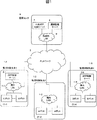
図1は本実施例における運用監視システムの構成の一例である。 FIG. 1 is an example of the configuration of the operation monitoring system in this embodiment.
運用監視システムは機器を設置した拠点を監視対象拠点(1−1〜1−N)とし、監視対象拠点に設置した監視対象機器を監視する。設置された機器は種々のアプリケーションを通じて利用者へサービスを提供する。 The operation monitoring system sets the base where the equipment is installed as the monitoring target base (1-1 to 1-N), and monitors the monitored equipment installed at the monitoring target base. The installed equipment provides services to users through various applications.
監視対象機器には様々な形態があるが、ここでは、ロボットと呼ぶ21−1〜21−Nの「自律移動が可能な情報処理装置(以降ロボット21と総称)を対象として説明する。 There are various types of monitored devices, but here, 21-1 to 21-N "information processing devices capable of autonomous movement (hereinafter collectively referred to as robot 21)" called robots will be described.
ロボット21は制御端末を含むため、ロボット21自身の機構制御の他に、サーバと同様にアプリケーションを実行し利用者へサービスを提供することが可能だが、ロボット21の制御端末はサーバのようにアプリケーションの実行に特化しているわけではない。このため、アプリケーションの実行に利用可能なCPU、内部記憶(メモリ)や外部記憶(ストレージ)などの計算機資源はサーバほど潤沢ではない。
Since the
このため、アプリケーションの実行を外部に設置したサーバに依存する場合もある。この場合、外部に設置したサーバにサービス要求を行い、サーバからサービス処理結果を受け取り利用者にサービスを提供する。サーバの設置個所は、ロボット21と同じ監視対象拠点に設置する方法と、データセンタまたは監視センタに設置する方法の2通りがある。
Therefore, the execution of the application may depend on the server installed externally. In this case, the service is requested to the server installed outside, the service processing result is received from the server, and the service is provided to the user. There are two ways to install the server, one is to install it at the same monitoring target base as the
監視対象拠点(1−1〜1−N)に設置したサーバをアプリケーション制御サーバ(3−1〜3−N、以下APP制御サーバ3と記載)、監視拠点である監視センタ6に設置したサーバを中央アプリケーション制御サーバ7(以下中央APP制御サーバ7と記載)と呼ぶ。これらのサーバは、サービス要求処理装置として機能する。
The server installed at the monitoring target base (1-1 to 1-N) is the application control server (3-1 to 3-N, hereinafter referred to as APP control server 3), and the server installed at the
各監視対象拠点1において、ロボット21とAPP制御サーバ3は、拠点内LANである構内LAN(4−1〜4−N)で接続され、監視センタ6において、運用監視サーバ8と中央APP制御サーバ7は拠点内LAN9で接続される。ロボット21、APP制御サーバ3と中央APP制御サーバ7は、構内LAN4または拠点内LAN9と、拠点間ネットワーク5と、を通じて相互に接続される。
At each
各拠点に設置されたロボット21、APP制御サーバ3と中央APP制御サーバ7は、機器運用監視システム内の機器、サーバを統括管理する運用監視サーバ8によって制御される。ロボット21、APP制御サーバ3および中央APP制御サーバ7は、運用監視に必要な種々の情報を運用監視サーバ8に送信する。
The
次に、システムを構成する各装置について詳しく説明する。 Next, each device constituting the system will be described in detail.
図2はロボット21の装置構造を示す。ロボット21は、ロボット制御端末2と、制御対象のカメラ291、モータ292、マイク293、スピーカー294、アクチュエータ295、各種センサ296を含んで構成され、ロボット制御端末2と制御対象の各デバイスは、ロボット制御端末2の外部入出力インターフェース29を通じて接続される。
FIG. 2 shows the device structure of the
ロボット制御端末2はバス28に接続された制御部(CPU)22、メモリなどの内部記憶装置26、ハードディスクなどの外部記憶装置24、及びネットワークインターフェース20を具備し、ネットワークインターフェース20、構内LAN4および拠点間ネットワーク5を介して通信を行う。
The robot control terminal 2 includes a control unit (CPU) 22 connected to the
内部記憶装置26には、ロボット21の機構、姿勢、移動等を制御するロボット制御アプリケーション261を含む。内部記憶装置26はさらに、ロボット21自身の制御以外の機能、例えばセンサーによる情報収集や位置推定などの各種アプリケーション(262、263)を備える。各種アプリケーションはロボット21が必要とする機能に応じて複数起動することが可能である。
The
これらのアプリケーションに加えて、ロボット21はロボットの状態に関する情報を管理するロボット状態データベース(DB)264、ロボット21のリソース使用状況を管理するロボットリソースDB265、ロボット21が利用している各種アプリケーションの接続先を管理するAPP接続先情報DB266を備える。
In addition to these applications, the
これらの各データベースは、システムの規模、ロボット制御端末21の処理性能などに応じて、外部記憶装置24に格納してもよい。これらのデータベースは内部記憶装置26にインストールされているロボット制御アプリケーション261によって読み書きが行われる。
Each of these databases may be stored in the
制御部(CPU)22が内部記憶装置26に保存されたロボット制御アプリケーション261にアクセスすることで、ロボット21の制御機能が実現される。
The control function of the
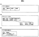
図3はロボット21の内部記憶装置26に存在する各種のデータベースの構造を表す。ロボット状態DB264はロボット21自身の状態に関する情報を管理するデータベースであり、ロボット21が設置されている監視対象拠点1の拠点マップ、場所名、X座標、Y座標を含む。
FIG. 3 shows the structure of various databases existing in the
拠点マップは設置拠点の形状、広さなど、拠点の物理的構造に関する情報であり、ロボット21の設置時に情報の初期化が行われる。ロボット21には自己位置推定機能があり、レーザーレンジファインダ等を用いて周囲の壁と自身の距離を測定することで、監視対象拠点1内の自身の位置(X座標、Y座標)を判定できる。
The base map is information on the physical structure of the base such as the shape and size of the installation base, and the information is initialized when the
拠点マップは拠点の物理的構造の他、場所に関する情報も含む。例えば座標を用いて拠点内の部屋に関する情報を定義することが可能である。 The base map contains information about the location as well as the physical structure of the base. For example, it is possible to define information about a room in the base using coordinates.
ロボットリソースDB265はロボット制御端末2の計算機資源の利用状況を管理するデータベースであり、ロボット21が設置されている監視対象拠点1の拠点識別子、当該拠点のネットワーク(NW)帯域、ネットワーク帯域利用率と、ロボット制御端末上で稼働しているアプリケーションのリストである稼働中APPリストを含む。稼働中APPリストの一項目は、システム内でアプリケーションを一意に特定するAPP識別子、当該アプリケーションのCPU使用率と消費NW帯域を含む。
The
APP接続先情報DB266は、ロボット21が利用するアプリケーションのうち外部のサーバで動作しているアプリケーションの接続先を管理するデータベースであり、APP識別子と接続先を含む。例えば、音声認識処理が拠点内のAPP制御サーバ3で動作している場合、音声認識処理の接続先はAPP制御サーバ3となる。
The APP connection destination information DB266 is a database that manages the connection destination of the application running on the external server among the applications used by the
図4はAPP制御サーバ3の装置構造を示す。APP制御サーバ3はバス38に接続された制御部(CPU)32、メモリなどの内部記憶装置36、ハードディスクなどの外部記憶装置34、及びネットワークインターフェース30を具備し、ネットワークインターフェース30、構内LAN4および拠点間ネットワーク5を介して通信を行う。
FIG. 4 shows the device structure of the
内部記憶装置36には、アプリケーションの実行、起動、停止処理を行うAPP制御アプリケーション361を含む。内部記憶装置36はさらに、ロボット21に種々の機能を提供するための各種アプリケーション(362、363)を備える。
The
各種アプリケーションはロボット21が必要とする機能に応じて複数起動することが可能である。アプリケーションは外部記憶装置34にインストールされ、制御部(CPU)32によって必要時に起動される。
A plurality of various applications can be started according to the functions required by the
これらのアプリケーションに加えて、APP制御サーバ3は拠点の基本的な情報を管理する拠点基本情報DB364、拠点の計算機資源の利用状況を管理する拠点リソースDB365、拠点の種々の状態を管理する拠点状態DB366、拠点内の全てのロボット21のAPP接続状況を管理するロボット接続情報DB367、拠点内の全てのロボット21の状態を管理するロボット状態DB368、拠点内の全てのロボット21のリソース利用状況を管理するロボットリソースDB369を備える。
In addition to these applications, the
これらの各データベースは、システムの規模、APP制御サーバ3の処理性能などに応じて、外部記憶装置34に格納してもよい。これらのデータベースは内部記憶装置36に読み込まれ、実行されているAPP制御アプリケーション261によって読み書きが行われる。
Each of these databases may be stored in the external storage device 34 according to the scale of the system, the processing performance of the
制御部(CPU)32が内部記憶装置36に保存されたAPP制御アプリケーション361にアクセスすることで、APP制御サーバ3はアプリケーション制御処理を実行する。
When the control unit (CPU) 32 accesses the
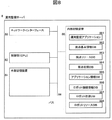
図5はAPP制御サーバ3の内部記憶装置36に存在する各種のデータベースの構造を表す。拠点基本情報DB364は監視対象拠点1の基本的な情報を管理するデータベースであり、システム内で監視対象拠点1を一意に特定する拠点識別子と、固定APPリストを含む。
FIG. 5 shows the structures of various databases existing in the
固定APPリストとはアプリケーションのうち必ず当該管理拠点1に設置されたAPP制御サーバ3で実行しなければならない、逆に言えばロボット21や中央APP制御サーバ7で実行してはならないアプリケーションの識別子のリストである。
The fixed APP list is an identifier of an application that must be executed by the
例えば、雑音に強い音声認識アプリケーションは、拠点の物理的構造に影響を受けるため、拠点内に実行環境がある方が望ましい。拠点基本情報DBはこのようなアプリケーションのリストを保持する。 For example, a voice recognition application that is resistant to noise is affected by the physical structure of the base, so it is desirable that the base has an execution environment. The base basic information DB holds a list of such applications.
拠点リソースDB365はAPP制御サーバ3の計算機資源の利用状況を管理するデータベースであり、APP制御サーバ3が設置されている監視対象拠点1の拠点識別子、当該拠点のネットワーク(NW)帯域、ネットワーク帯域利用率と、APP制御サーバ3上で稼働しているアプリケーションのリストである稼働中APPリストを含む。稼働中APPリストの一項目は、システム内でアプリケーションを一意に特定するAPP識別子、当該アプリケーションのCPU使用率と消費NW帯域を含む。
The
拠点状態DB366は拠点の種々の状態を管理するデータベースであり、拠点識別子、拠点マップ、拠点業務スケジュールを含む。拠点識別子と拠点マップは監視対象拠点内の全てのロボット21と共有される。拠点業務スケジュールは監視対象拠点において実行される業務のスケジュールに関する情報を管理し、場所名、業務の開始時刻、終了時刻と業務内容を含む。
The base status DB366 is a database that manages various statuses of the base, and includes a base identifier, a base map, and a base business schedule. The base identifier and the base map are shared with all the
例えば、監視対象拠点1が銀行の場合、応対フロアでは、銀行の営業時間では預金の預け入れ、融資の相談などの通常の銀行業務が行われるが、銀行の営業時間外では応対フロアは不審人物の監視と検出が主な業務となるなど、時間帯によって提供業務が異なる。
For example, if the monitored
ロボット接続情報DB367は監視対象拠点1内のロボット21のアプリケーション利用状況を管理するデータベースであり、システム内でロボット21を一意に特定するロボット識別子、ロボット21が利用中のアプリケーションを識別するAPP識別子、アプリケーションが消費するネットワーク帯域とCPU使用率を含む。
The robot connection information DB367 is a database that manages the application usage status of the
ロボット状態DB368は同一拠点に設置されているすべてのロボット21の状態を管理するデータベースであり、基本的な構造はロボット21のロボット状態DB264と同様である。
The
複数のロボット21の状態を管理するために、ロボット21のロボット状態DB264に加えてロボット識別子を含む。
In order to manage the states of the plurality of
ロボットリソースDB369は同一拠点に設置されているすべてのロボット21の計算機資源の利用状況を管理するデータベースであり、基本的な構造はロボット21のロボットリソースDB265と同様である。複数のロボット21の状態を管理するために、ロボット21のロボットリソースDB265に加えてロボット識別子を含む。
The
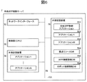
図6は中央APP制御サーバ7の装置構造を示す。中央APP制御サーバ7はバス78に接続された制御部(CPU)72、メモリなどの内部記憶装置76、ハードディスクなどの外部記憶装置74、及びネットワークインターフェース70を具備し、ネットワークインターフェース70、拠点内LAN9および拠点間ネットワーク5を介して通信を行う。
FIG. 6 shows the device structure of the central
内部記憶装置76には、アプリケーションの実行、起動、停止処理を行う中央APP制御アプリケーション761を含む。内部記憶装置76はさらに、ロボット21に種々の機能を提供するための各種アプリケーション(762、763)を備える。各種アプリケーションはロボット21が必要とする機能に応じて複数起動することが可能である。
The
アプリケーションは外部記憶装置74にインストールされ、制御部(CPU)72によってシステムの稼働開始時に起動される。これらのアプリケーションに加えて、中央APP制御サーバ7は監視センタの計算機資源の利用状況を管理する拠点リソースDB764、拠点のアプリケーションの利用状況を管理するAPP接続情報DB765、中央APP制御サーバ7に接続する全てのロボット21のAPP接続状況を管理するロボット接続情報DB766を備える。
The application is installed in the
これらの各データベースは、システムの規模、中央APP制御サーバ7の処理性能などに応じて、外部記憶装置74に格納してもよい。これらのデータベースは内部記憶装置76にインストールされている中央APP制御アプリケーション761によって読み書きが行われる。
Each of these databases may be stored in the
制御部(CPU)72が内部記憶装置76に保存された中央APP制御アプリケーション761にアクセスすることで、中央APP制御サーバ7は中央アプリケーション制御処理を実行する。
When the control unit (CPU) 72 accesses the central
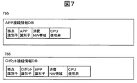
図7は中央APP制御サーバ7の内部記憶装置76に存在する各種のデータベースの構造を表す。拠点リソースDB764は監視センタ6の計算機資源の利用状況を管理するデータベースであり、APP制御サーバ3の拠点リソースDB365と同様の構造を持つ。
FIG. 7 shows the structures of various databases existing in the
APP接続情報DB765は全ての監視対象拠点1のアプリケーション利用状況を管理するデータベースであり、システム内で監視対象拠点1を一意に特定する拠点識別子、監視対象拠点1が利用中のアプリケーションを識別するAPP識別子、アプリケーションが消費するネットワーク帯域とCPU使用率を含む。
The APP connection information DB765 is a database that manages the application usage status of all the monitored
ロボット接続情報DB766は図1の監視対象拠点2(1−2)のように、APP制御サーバ3の存在しない監視対象拠点のロボット21のアプリケーション利用状況を管理するデータベースであり、システム内で監視対象拠点1を一意に特定する拠点識別子、ロボット識別子、ロボット21が利用中のアプリケーションを識別するAPP識別子、アプリケーションが消費するネットワーク帯域とCPU使用率を含む。
The robot
図8は運用監視サーバ8の装置構造を示す。運用監視サーバ8はバス88に接続された制御部(CPU)82、メモリなどの内部記憶装置86、ハードディスクなどの外部記憶装置84、及びネットワークインターフェース80を具備し、ネットワークインターフェース80、拠点内LAN9および拠点間ネットワーク5を介して通信を行う。
FIG. 8 shows the device structure of the
内部記憶装置86には、システム内の全てのロボット21、APP制御サーバ3の運用監視を統合して行う運用監視アプリケーション861を含む。
The
内部記憶装置86はさらに、運用監視制御サーバ8はさらに、監視対象拠点(1−1〜1−N)の基本的な情報を管理する拠点基本情報DB862、監視対象拠点(1−1〜1−N)の計算機資源の利用状況を管理する拠点リソースDB863、監視対象拠点(1−1〜1−N)の種々の状態を管理する拠点状態DB864、アプリケーションの利用状況に応じてアプリケーションの稼働場所を制御するための条件を管理するアプリケーション情報DB865、システム内のロボット(21−1〜21−N)のアプリケーション利用状況を管理するロボット接続情報DB866、システム内のロボット(21−1〜21−N)の状態を管理するロボット状態DB867、システム内のロボット(21−1〜21−N)のリソース利用状況を管理するロボットリソースDB868を備える。
The
これらの各データベースは、システムの規模、運用監視サーバ8の処理性能などに応じて、外部記憶装置84に格納してもよい。これらのデータベースは内部記憶装置86にインストールされている運用監視アプリケーション861によって読み書きが行われる。
Each of these databases may be stored in the
制御部(CPU)82が内部記憶装置86に保存された運用監視アプリケーション861にアクセスすることで、運用監視サーバ8はシステムの統合管理を実行する。
When the control unit (CPU) 82 accesses the
運用監視サーバ8の内部記憶装置86に含まれるデータベースのうち、アプリケーション情報DB865以外のデータベースは、ロボット21、あるいは監視対象拠点1の情報を一元管理するためのデータベースであり、データ構造が一致する同名のデータベースが他のサーバに存在する。
Of the databases included in the
それぞれのデータベースの対応関係は以下の通りである。
・拠点基本情報DB862:APP制御サーバ3の拠点基本情報DB364
・拠点リソースDB863:APP制御サーバ3の拠点リソースDB365
・拠点状態DB864:APP制御サーバ3の拠点状態DB366
・ロボット接続情報DB866:APP制御サーバ3のロボット接続情報DB367
・ロボット状態DB867:APP制御サーバ3のロボット状態DB368
・ロボットリソースDB:APP制御サーバ3のロボットリソースDB369
これらのデータベースの構造に関する説明は割愛し、ここでは図9を用いてアプリケーション情報DB865について説明する。
The correspondence between each database is as follows.
-Base basic information DB862: Base basic information DB364 of
-Base resource DB863: Base resource DB365 of
-Base status DB864: Base status DB366 of
-Robot connection information DB866: Robot connection information DB367 of the
-Robot state DB867: Robot state DB368 of
-Robot resource DB:
The description of the structure of these databases is omitted, and here, the
アプリケーション情報DB865はアプリケーションの実行環境を管理するデータベースである。
The
本実施例におけるAPP制御サーバの変更とは、アプリケーションの実行場所をある装置(ロボットまたはサーバ)から他の装置(ロボットまたはサーバ)に変更する処理を指す。具体的には、アプリケーションプログラムを移動しても良いし、複数のサーバの各々が同じ機能を提供するアプリケーションプログラムを格納しておき、アプリケーションプログラムを移動せずに、実行する装置を切り替えても良い。 The change of the APP control server in this embodiment refers to the process of changing the execution location of the application from a certain device (robot or server) to another device (robot or server). Specifically, the application program may be moved, or the application program that provides the same function may be stored in each of the plurality of servers, and the device to be executed may be switched without moving the application program. ..
変更のパターンは下記6通りが存在する
(1)ロボット21からAPP制御サーバ3へ変更
(2)APP制御サーバ3からロボット21へ変更
(3)APP制御サーバ3から中央APP制御サーバ7へ変更
(4)中央APP制御サーバ7からAPP制御サーバ3へ変更
(5)ロボット21から中央APP制御サーバ7へ変更
(6)中央APP制御サーバ7からロボット21へ変更
上記のサービス要求処理装置として機能する制御サーバの変更規則を管理するデータベースがアプリケーション情報DB865である。アプリケーション情報DB865は変更条件を一意に特定する条件識別子、実行する装置の変更対象となるアプリケーションの識別子、変更種別、変更条件を含む。
There are 6 patterns of change as follows: (1) Change from
変更種別は固定か変更可の2つの値を取り、固定の場合はサービス要求処理装置として機能する制御サーバの変更は適用できない。変更可の場合、変更条件によって変更要否の判定がなされる。変更条件は変更方向、判定条件数と具体的な判定条件を含む。判定条件は1つの条件識別子に対して複数指定することが可能である。変更判定の詳細については後述する。変更方向は上記6パターンのいずれかに該当する。 The change type takes two values, fixed or changeable, and in the case of fixed, the change of the control server that functions as the service request processing device cannot be applied. If the change is possible, the necessity of the change is determined according to the change conditions. The change conditions include the change direction, the number of judgment conditions, and specific judgment conditions. A plurality of determination conditions can be specified for one condition identifier. The details of the change determination will be described later. The change direction corresponds to any of the above six patterns.
続いて、本実施例における機器運用監視システムの全体の動作について説明する。 Next, the overall operation of the device operation monitoring system in this embodiment will be described.
まず図10の時系列図を用いて、APP制御サーバ3から中央APP制御サーバ7へサービス要求処理装置を変更する制御の流れについて説明する。
First, the flow of control for changing the service request processing device from the
ロボット21の計算機資源が限られている場合、多くのアプリケーションはロボット21の外部で動作する。ロボット21から見た外部はAPP制御サーバ3もしくは中央APP制御サーバ7であるため、サービス要求処理装置として機能する制御サーバの変更は、この両者間で発生するケースが多い。
When the computer resources of the
サービス要求処理装置として機能する制御サーバの変更処理は運用監視サーバ8によって制御されるため、APP制御サーバ3と中央APP制御サーバ7は運用監視サーバ8に制御に必要な情報を送信する。
Since the change processing of the control server that functions as the service request processing device is controlled by the
例えば、一つ以上の監視対象拠点にあるAPP制御サーバ3が自拠点のリソースに関する情報を収集し(S1−01)、拠点リソースDB365を更新して収集した情報を拠点リソース情報として運用監視サーバ8に送信する(S1−04)。送信される拠点リソース情報の内容は、拠点リソースDB365の対応する項目の内容と一致する。
For example, the
拠点リソース情報を送信した後、各APP制御サーバ3は自拠点の拠点状態に関する情報の収集を行い(S1−07)、拠点状態DB366を更新して、収集した情報を拠点状態情報として運用監視サーバ8に送信する(S1−10)。
After transmitting the base resource information, each
なお、各APP制御サーバ3によるS1−01〜S1−10の実行順序は上記以外でも良い。
The execution order of S1-01 to S1-10 by each
中央APP制御サーバ7も同様にリソース情報を収集して(S1−13)拠点リソースDB764を更新し、拠点リソース情報を運用監視サーバ8に送信する(S1−16)。
Similarly, the central
なお、各APP制御サーバ3による情報送信と、中央APP制御サーバ7による情報送信の実行順序と、は上記以外でも良い。
The information transmission by each
運用監視サーバ8はAPP制御サーバ3、中央APP制御サーバ7から収集した拠点リソース情報、拠点状態情報に基づき、サービス要求処理装置の変更が必要なアプリケーションがあるか否か判定する(S1−19)。サービス要求処理装置の変更要否判定アルゴリズムについては後述する。
The
ここで、APP制御サーバ3から中央APP制御サーバ7へサービス要求処理装置の変更が必要なアプリケーションが存在すれば、運用監視サーバ8は当該アプリケーションが稼働しているAPP制御サーバ3を特定し、当該APP制御サーバ3と同じ監視対象拠点1にあるロボット21に対して、サーバ変更通知メッセージ(以下、サーバ変更通知)を送信し、変更後のサービス要求処理装置を登録させる(S1−22)。
Here, if there is an application that needs to change the service request processing device from the
サーバ変更通知はアプリケーション識別子とアプリケーションの接続先情報とを含む。アプリケーションの接続先には中央APP制御サーバ7が指定される。
The server change notification includes the application identifier and the connection destination information of the application. The central
サービス要求処理装置の変更後にAPP制御サーバ3のリソースが浪費されるのを防ぐため、運用監視サーバ8はAPP制御サーバ3にAPP停止通知を送信する(S1−25)。APP停止通知を受信したAPP制御サーバ3は、対象となるアプリケーションの停止処理を行う(S1−28)。
In order to prevent the resources of the
サービス要求処理装置の変更通知を受信したロボット21は、指定されたアプリケーションを利用するときはサービス要求メッセージを中央APP制御サーバ7に送信する(S1−31)。中央APP制御サーバ7は、上記アプリケーションを実行して、上記サービス要求を処理して、サービス処理結果をロボット21に返送する(S1−34)。
Upon receiving the change notification of the service request processing device, the
次に図11の時系列図を用いて、アプリケーションを実行する装置を中央APP制御サーバ7からAPP制御サーバ3へ変更する制御の流れについて説明する。
Next, the flow of control for changing the device for executing the application from the central
サービス要求処理装置の変更処理は運用監視サーバ8によって制御されるため、APP制御サーバ3、中央APP制御サーバ7は運用監視サーバ8に制御に必要な情報を送信する。情報収集、送信処理に関しては、図11のステップS2−01〜S2−16の処理は図10のステップS1−01〜S1−16と同一であるため、説明を割愛する。
Since the change processing of the service request processing device is controlled by the
ステップS2−19において、運用監視サーバ8は実行する装置の変更が必要なアプリケーションがあるか否か判定する。ここで、装置の変更が必要なアプリケーションが存在し、変更方向が中央APP制御サーバ7からAPP制御サーバ3であったとすると、運用監視サーバ8はサービス要求処理装置の変更を準備するために、変更先のAPP制御サーバ3にAPP起動通知を送信する(S2−22)。
In step S2-19, the
APP起動通知を受信したAPP制御サーバ3は、指定されたアプリケーションを起動する(S2−25)。運用監視サーバ8はAPP起動通知の送信後に、サービス要求処理装置の変更対象のAPP制御サーバ3に関連したロボット21に対し、サーバ変更通知を送信する(S2−28)。
Upon receiving the APP start notification, the
サーバ変更通知には、実行する装置が変更されるAPP識別子と接続先としてAPP制御サーバ3が指定される。サーバ変更通知を受信した後は、アプリケーション処理はロボット21とAPP制御サーバ3の間で行われる(S2−31、S2−34)。
In the server change notification, the APP identifier to which the device to be executed is changed and the
アプリケーションの中にはロボット21で実行されるものがあるため、サービス要求処理装置の変更はロボット21とAPP制御サーバ3、中央APP制御サーバ7の間でも発生しうる。
Since some applications are executed by the
図12の時系列図はアプリケーションの実行装置をロボット21からAPP制御サーバ3へ変更する場合の処理を示している。この場合、運用監視サーバ8はロボット21のリソース使用状況および状態を把握する必要がある。
The time-series diagram of FIG. 12 shows the processing when the execution device of the application is changed from the
そこで、ロボット21はリソース情報、状態情報を収集し(S3−01、S3−10)、これらをAPP制御サーバ3へ送信する(S3−04、S3−13)ロボットリソース情報の内容はロボットリソースDB369と一致する。また、ロボット状態情報の内容はロボット状態DB368と一致する。
Therefore, the
ロボット21からロボットリソース情報、ロボット状態情報を受信したAPP制御サーバ3は、これらの情報を運用監視サーバ8に送信する(S3−07、S3−16)。APP制御サーバ3、中央APP制御サーバ7は、図10のステップS1−01〜S1−16と同様の方法で、拠点リソース情報、拠点状態情報を運用監視サーバ8に送信する(S3−19〜S3−34)。
The
運用監視サーバ8は収集した各ロボットリソース情報、ロボット状態情報、拠点リソース情報、拠点状態情報に基づき、サービス要求処理装置の変更要否を判定する(S3−37)。このケースではアプリケーションを実行する装置をロボット21からAPP制御サーバ3へ変更するため、運用監視サーバ8はAPP制御サーバ3に対し、新たな実行対象となるアプリケーションの起動通知を送信する(S3−40)。
The
APP起動通知は起動対象のアプリケーション識別子を指定する。APP制御サーバ3は指定されたアプリケーションを起動する(S3−43)。
The APP start notification specifies the application identifier to be started. The
その後、運用監視サーバ8はロボット21に対してサーバ変更通知を送信し(S3−46)、対象のアプリケーションがAPP制御サーバ3で実行中であることをロボット21に通知する。
After that, the
ロボット21は対象のアプリケーションの接続先がAPP制御サーバ3になるようAPP接続先情報DB266を更新し、ロボット21で稼働中の当該アプリケーションを停止する(S3−49)。
The
以降、当該アプリケーションの処理はロボット21とAPP制御サーバ3の間でメッセージの送受信を通じて行われる(S3−52、S3−55)。
After that, the processing of the application is performed through the transmission and reception of messages between the
ロボット21を含めたサービス要求処理装置の変更については、図12のケースのほかに、下記の3つのケースが考えられる。
(1)APP制御サーバ3からロボット21へサービス要求処理装置を変更
(2)ロボット21から中央APP制御サーバ7へサービス要求処理装置を変更
(3)中央APP制御サーバ7からロボット21へサービス要求処理装置を変更
図13はAPP制御サーバ3からロボット21へサービス要求処理装置を変更するケースの時系列図である。ロボット21、APP制御サーバ3、中央APP制御サーバ7から各種の情報を収集する処理(S4−01〜S4−34)は図12のステップS3−01〜S3−34と同様であるため、説明を割愛する。
Regarding the change of the service request processing device including the
(1) Change the service request processing device from the
ステップS4−37において、運用監視サーバ8はAPP制御サーバ3からロボット21へサービス要求処理装置を変更すると判断し、サーバ変更通知をロボット21へ送信する(S4−40)。
In step S4-37, the
サーバ変更通知を受信したロボット21は、サービス要求処理装置の変更対象が自身であることを知り、アプリケーション識別子で指定されたアプリケーションを起動する(S4−43)。
Upon receiving the server change notification, the
運用監視サーバ8はAPP制御サーバ3にAPP停止通知を送信し(S4−46)、APP制御サーバ3は指定されたアプリケーションを停止させる(S4−49)。
The
図14はロボット21から中央APP制御サーバ7にサービス要求処理装置を変更させるケースの時系列図である。
FIG. 14 is a time-series diagram of a case where the
本来、ロボット21の負荷軽減を目的としたときのサービス要求処理装置の変更先は、ロボット21と同じ監視対象拠点1に設置したAPP制御サーバ3であることが望ましいが、APP制御サーバ3の処理負荷がきわめて高い場合などに、中央APP制御サーバ7への変更処理を検討する。
Originally, it is desirable that the change destination of the service request processing device for the purpose of reducing the load on the
ロボット21、APP制御サーバ3、中央APP制御サーバ7から各種の情報を収集する処理(S5−01〜S5−34)は図12のステップS3−01〜S3−34と同様であるため、説明を割愛する。
The process of collecting various information from the
ステップS5−37において、運用監視サーバ8はロボット21から中央APP制御サーバ7へサービス要求処理装置を変更させると判断し、サーバ変更通知をロボット21へ送信する(S5−40)。
In step S5-37, the
サーバ変更通知を受信したロボット21は、指定されたアプリケーションの接続先が中央APP制御サーバ7となるようAPP接続先情報DB266を更新し、指定されたアプリケーションを停止させる(S5−43)。
Upon receiving the server change notification, the
以降、当該アプリケーションの処理はロボット21と中央APP制御サーバ7の間でメッセージの送受信を通じて行われる(S5−46、S5−49)。
After that, the processing of the application is performed through the transmission and reception of messages between the
図15は中央APP制御サーバ7からロボット21にサービス要求処理装置を変更させるケースの時系列図である。
FIG. 15 is a time-series diagram of a case where the central
図14の状態からロボット21の処理負荷が下がり、元の状態に復旧するケースが該当する。ロボット21、APP制御サーバ3、中央APP制御サーバ7から各種の情報を収集する処理(S6−01〜S6−34)は図12のステップS3−01〜S3−34と同様であるため、説明を割愛する。
This corresponds to the case where the processing load of the
ステップS6−37において、運用監視サーバ8は中央APP制御サーバ7からロボット21へサービス要求処理装置を変更すると判断し、サーバ変更通知をロボット21へ送信する(S5−40)。
In steps S6-37, the
サーバ変更通知を受信したロボット21は、指定されたアプリケーションの接続先がロボット21自身となるようAPP接続先情報DB266を更新し、指定されたアプリケーションを起動する(S6−43)。当該アプリケーションの処理はロボット21が行う。
Upon receiving the server change notification, the
拠点によっては図1の監視対象拠点2(1−2)のように、APP制御サーバ3がないケースがある。この場合、ロボット21は中央APP制御サーバ7を通じて運用監視サーバ8へ各種の情報を送信する。図16はこのような状況において、アプリケーションを実行する装置をロボット21から中央APP制御サーバ7へ変更する場合の時系列図である。
Depending on the base, there is a case where the
ロボット21はリソース情報、状態情報を収集し(S7−01、S7−07)、これらを中央APP制御サーバ7へ送信する(S7−04、S7−10)ロボットリソース情報の内容はロボットリソースDB369と一致する。また、ロボット状態情報の内容はロボット状態DB368と一致する。
The
ロボット21からロボットリソース情報、ロボット状態情報を受信した中央APP制御サーバ7は、これらの情報を運用監視サーバ8に送信する(S7−05、S7−11)。中央APP制御サーバ7は、図10のステップS1−13、S1−16と同様の方法で、拠点リソース情報を運用監視サーバ8に送信する(S7−13〜S7−16)。
The central
運用監視サーバ8は収集した各ロボットリソース情報、ロボット状態情報、拠点リソース情報に基づき、サービス要求処理装置の変更要否を判定する(S7−19)。このケースではアプリケーションを稼働させる装置を、ロボット21から中央APP制御サーバ7へ変更するため、運用監視サーバ8はロボット21に対してサーバ変更通知を送信し(S7−22)、対象のアプリケーションが中央APP制御サーバ7で実行中であることをロボット21に通知する。
The
ロボット21は対象のアプリケーションの接続先が中央APP制御サーバ7になるようAPP接続先情報DB266を更新し、ロボット21で稼働中の当該アプリケーションを停止する(S7−25)。
The
以降、当該アプリケーションの処理はロボット21と中央APP制御サーバ7の間でメッセージの送受信を通じて行われる(S7−28、S7−31)。
After that, the processing of the application is performed through the transmission and reception of messages between the
図17は図16とは逆のケースで、アプリケーションの実行装置を中央APP制御サーバ7からロボット21へ変更する場合の時系列図である。ロボット21、中央APP制御サーバ7から各種の情報を収集する処理(S8−01〜S8−16)は図16のステップS7−01〜S7−16と同様であるため、説明を割愛する。
FIG. 17 is a time-series diagram in the opposite case of FIG. 16 when the application execution device is changed from the central
ステップS8−19において、運用監視サーバ8は中央APP制御サーバ7からロボット21へサービス要求処理装置を変更させると判断し、サーバ変更通知をロボット21へ送信する(S8−22)。サーバ変更通知を受信したロボット21は、指定されたアプリケーションの接続先がロボット21となるようAPP接続先情報DB266を更新し、指定されたアプリケーションを起動する(S8−25)。
In step S8-19, the
監視対象拠点1に複数台のロボット21が設置されている場合、サービス要求処理装置の変更は各ロボット21に対して行う。
When a plurality of
図18は監視対象拠点1に2台のロボット1(21−1)、ロボット2(21−2)が設置されている場合のサービス要求処理装置変更の判定処理を表す時系列図である。ここでは、ロボット1(21−1)、ロボット2(21−2)が最初は同じ場所にあったが、ロボット1(21−1)が場所を移動した(S9−01)ものと想定する。
FIG. 18 is a time-series diagram showing a determination process of changing the service request processing device when two robots 1 (21-1) and robots 2 (21-2) are installed at the monitored
場所が移動すると、ロボット21がシステム内で担う役割が変化する。例えば銀行を例にとると、金庫室ではセキュリティ監視が主な業務となるのに対し、顧客応対フロアでは種々の応対業務を行う必要がある。
When the place moves, the role played by the
ロボット21が拠点に複数存在する場合、各ロボット21はロボットリソース情報、ロボット状態情報の収集、通知をそれぞれ行う(S9−04〜S9−26)。
When a plurality of
APP制御サーバ3がロボットリソース情報およびロボット状態情報を運用監視サーバ8に送信する場合(S9−14、S9−26)は、監視対象拠点内のロボット(21−1〜21−N)の情報を一括して送信する。
When the
APP制御サーバ3、中央APP制御サーバ7は、これまでの処理と同様の方法で拠点リソース情報、拠点状態情報の収集を行い、運用監視サーバ8に送信する(S9−28〜S9−43)。
The
サービス要求処理装置の変更判定(S9−46)において、ロボット1(21−1)のあるアプリケーションをAPP制御サーバ3で稼働させる必要があると判断したとする。
It is assumed that in the change determination (S9-46) of the service request processing device, it is determined that an application having the robot 1 (21-1) needs to be operated on the
運用監視サーバ8はAPP制御サーバ3に対し、実行させる装置の変更対象となるアプリケーションの起動通知を送信する(S9−49)。APP起動通知は起動対象のアプリケーション識別子を指定する。APP制御サーバ3は指定されたアプリケーションを起動する(S3−52)。
The
その後、運用監視サーバ8はロボット1(21−1)に対してサーバ変更通知を送信し(S9−55)、対象のアプリケーションがAPP制御サーバ3で実行中であることをロボット1(21−1)に通知する。ロボット1(21−1)は対象のアプリケーションの接続先がAPP制御サーバ3になるようAPP接続先情報DB266を更新する。
After that, the
以降、当該アプリケーションの処理はロボット1(21−1)とAPP制御サーバ3の間でメッセージの送受信を通じて行われる(S9−58、S9−61)。 After that, the processing of the application is performed through the transmission and reception of messages between the robot 1 (21-1) and the APP control server 3 (S9-58, S9-61).
次に、図19のフローチャートを用いて、運用監視サーバ8におけるサービス要求処理装置の変更判定方法について説明する。
Next, a change determination method of the service request processing device in the
サービス要求処理装置の変更判定は、運用監視サーバ8がロボット21、APP制御サーバ3、中央APP制御サーバ7から各種の情報を受信した後に行われる(図12のステップS3−37等)。起動契機としては、上記の各種情報の受信状況をチェックするほか、周期的に判定処理を起動する方法が考えられる。
The change determination of the service request processing device is performed after the
サービス要求処理装置変更の判定処理は、運用監視サーバ8のアプリケーション情報DB865で管理されているすべての条件識別子に対して行う(F1−04)。この処理は、アプリケーション情報DB865からある1つの条件識別子に対応したレコードを取得し、当該レコードに対する判定処理を実行することで実現できる(F1−07)。
The service request processing device change determination process is performed for all the condition identifiers managed by the
ここで、当該レコードの判定条件を用いてサービス要求処理装置変更の判定処理を行う(F1−10)、全ての判定条件が満たされている場合は、サービス要求処理装置の変更処理を実行する(F1−13)。そうでない場合は処理ループの先頭に戻り、別の条件識別子に対応したレコードのサービス要求処理装置変更の判定を行う(F1−04、F1−07)。 Here, the service request processing device change determination process is performed using the determination condition of the record (F1-10), and if all the determination conditions are satisfied, the service request processing device change process is executed (F1-10). F1-13). If not, the process returns to the beginning of the processing loop, and the service request processing device change of the record corresponding to another condition identifier is determined (F1-04, F1-07).
すべての条件識別子に対応したレコードに対して判定処理を完了した(F1−16)時点で、サービス要求処理装置変更の要否判定処理は終了する(F1−19)。 When the determination process is completed for the records corresponding to all the condition identifiers (F1-16), the necessity determination process for changing the service request processing device ends (F1-19).
サービス要求処理装置変更の判定における判定条件には様々なものが考えられる。 Various judgment conditions can be considered in the judgment of the service request processing device change.
図20は判定条件を設定する判定条件編集画面の一例である。判定条件の設定に必要な項目はアプリケーション名、変更種別、変更方向と変更判定条件である。アプリケーション名はアプリケーションを一意に特定できる必要があり、アプリケーション情報DB865のAPP識別子として使用される。
FIG. 20 is an example of a judgment condition editing screen for setting a judgment condition. The items required to set the judgment conditions are the application name, change type, change direction, and change judgment conditions. The application name must be able to uniquely identify the application and is used as the APP identifier of the
変更種別は変更可、もしくは固定の2つから選択する。変更可の場合は、変更の向きを選択して設定する。固定の場合はアプリケーションの配置拠点を設定する。固定を選択した場合、当該アプリケーションは拠点基本情報DB364の固定APPリストに登録される。 The change type can be changed or fixed. If it can be changed, select and set the direction of change. If it is fixed, set the location of the application. When fixed is selected, the application is registered in the fixed APP list of the base basic information DB364.
変更判定条件はサービス要求処理装置の変更条件を決定する項目であり、必要に応じて複数個登録することが可能である。変更判定条件に設定可能な項目としては、ロボット21、APP制御サーバ3、中央APP制御サーバ7のCPU使用率、消費ネットワーク帯域、ロボット21の位置、場所の業務などがあげられる。
The change determination condition is an item for determining the change condition of the service request processing device, and a plurality of change determination conditions can be registered as needed. Items that can be set in the change determination condition include the CPU usage rate of the
判定方法については、数値化可能な条件については以上、以下などの判定を行い、場所や業務内容など、文字列で表現される条件については文字列の内容で判定を行う。 Regarding the judgment method, the above and the following judgments are made for the conditions that can be quantified, and the judgment is made based on the contents of the character string for the conditions expressed by the character string such as the place and the business content.
例えば、銀行での顧客応対業務を例にとると、ロボット21が顧客応対スペースに移動し、主業務として顧客対応を行わなければならなくなった時点で、ロボット21のCPU負荷が10%と低い状態にあっても、当該サービス要求処理装置をAPP制御サーバ3へ変更する。
For example, taking the customer service business at a bank as an example, when the
逆に、ロボット21が顧客応対スペースから離脱し、顧客対応をする必要が無くなった場合、当該アプリケーションを使用する確率は低下するため、銀行顧客応対業務が万が一発生しても中央APP制御サーバ7で対処して、APP制御サーバ3の処理負荷を低減できる。
On the contrary, when the
サービス要求処理装置の変更パターンと具体例としては、以下の項目が考えられる。
(1)APP制御サーバ3から中央APP制御サーバ7へ
・ある拠点のAPPの利用率が低いため、中央APP制御サーバ7に集約
・時間帯による客層変化、サービス内容変更によるAPP利用率低下:夜間の顧客応対業務を中央APP制御サーバ7に集約化
(2)中央APP制御サーバ7からAPP制御サーバ3へ
・ある拠点から接続されているAPPの利用率が高い
・時間帯による客層変化、サービス内容変更によるAPP利用率上昇:ビジネスアワーの通常業務をAPP制御サーバ3で処理
(3)ロボット21からAPP制御サーバ3へ
・同一拠点で複数のロボット21が同一のアプリケーションを実行:APP制御サーバ3にアプリケーションを集約してロボット21の処理負荷を下げる
(4)APP制御サーバ3からロボット21へ
・(3)と逆の事象が発生
(5)ロボット21から中央APP制御サーバ7へ
・APP制御サーバ3がない拠点において、ロボット21の処理負荷を可能な範囲で低減する
(6)中央APP制御サーバ7からロボット21へ
・ロボット21の位置が特定の業務を提供する場所になった場合、応答時間の短縮を狙ってアプリケーションをロボットで実行する
上述した機器運用監視装置および機器運用監視システムは、多数の拠点に存在する種々の機器を統合管理する運用監視サービスへの適用が見込まれる。
The following items can be considered as change patterns and specific examples of the service request processing device.
(1) From
1:監視対象拠点
21:ロボット
3:APP制御サーバ
4:構内LAN
5:ネットワーク
6:監視センタ
7:中央APP制御サーバ
8:運用監視サーバ
1: Monitoring target base 21: Robot 3: APP control server 4: Local LAN
5: Network 6: Monitoring center 7: Central APP control server 8: Operation monitoring server
Claims (8)
自律移動可能な情報処理装置と、前記自律移動可能な情報処理装置からのサービス要求を処理するサービス要求処理装置と、のいずれか一方または両方が設置されている複数の拠点のいずれかに設置され、
前記自律移動可能な情報処理装置及び前記自律移動可能な情報処理装置が設置されている拠点それぞれの状態情報を取得し、
前記自律移動可能な情報処理装置の状態情報は、前記自律移動可能な情報処理装置の現在位置情報を含み、
前記自律移動可能な情報処理装置が設置されている拠点の状態情報は、前記自律移動可能な情報処理装置が設置されている拠点のマップ情報並びに前記自律移動可能な情報処理装置が設置されている拠点内での業務の場所及び時間の情報を含み、
前記自律移動可能な情報処理装置、前記自律移動可能な情報処理装置が設置されている拠点、及び前記運用監視サーバが設置されている拠点それぞれのリソース情報を取得し、
前記自律移動可能な情報処理装置のリソース情報は、前記自律移動可能な情報処理装置のリソース使用状況の情報を含み、
前記自律移動可能な情報処理装置が設置されている拠点のリソース情報は、前記自律移動可能な情報処理装置が設置されている拠点のリソース使用状況の情報を含み、
前記運用監視サーバが設置されている拠点のリソース情報は、前記運用監視サーバが設置されている拠点のリソース使用状況の情報を含み、
取得した前記状態情報及び前記リソース情報に基づき、前記自律移動可能な情報処理装置からのサービス要求を処理するサービス要求処理装置として、前記自律移動可能な情報処理装置が設置されている拠点にある第一のサービス要求処理装置、または、前記運用監視サーバが設置されている拠点に設置されている第二のサービス要求処理装置のいずれかを選択し、
前記自律移動可能な情報処理装置の状態情報及びリソース情報、並びに、前記自律移動可能な情報処理装置が設置されている拠点の状態情報及びリソース情報を、前記第一のサービス要求処理装置を介して取得する
ことを特徴とする運用監視サーバ。 It is an operation monitoring server
It is installed at one of a plurality of bases where one or both of the autonomously movable information processing device and the service request processing device for processing the service request from the autonomously movable information processing device are installed. ,
Acquiring the autonomous movable information processing apparatus and the autonomous movable information processing apparatus that is installed bases of each state information,
The state information of the autonomously movable information processing device includes the current position information of the autonomously movable information processing device.
As for the state information of the base where the autonomously movable information processing device is installed, the map information of the base where the autonomously movable information processing device is installed and the autonomously movable information processing device are installed. Including information on the location and time of work within the site
Obtain resource information for each of the autonomously movable information processing device, the site where the autonomously movable information processing device is installed, and the site where the operation monitoring server is installed.
The resource information of the autonomously movable information processing apparatus includes information on the resource usage status of the autonomously movable information processing apparatus.
The resource information of the base where the autonomously movable information processing device is installed includes information on the resource usage status of the base where the autonomously movable information processing device is installed.
The resource information of the site where the operation monitoring server is installed includes information on the resource usage status of the site where the operation monitoring server is installed.
A base where the autonomously movable information processing device is installed as a service request processing device that processes a service request from the autonomously movable information processing device based on the acquired state information and the resource information. one service request processing unit, or select one of the second service request processing device installed in the base for the operation monitoring server is installed,
The state information and resource information of the autonomously movable information processing device and the state information and resource information of the base where the autonomously movable information processing device is installed are transmitted via the first service request processing device. An operation monitoring server characterized by acquiring.
選択した前記サービス要求処理装置が、前記自律移動可能な情報処理装置に登録されている現用のサービス要求処理装置とは異なる場合、前記自律移動可能な情報処理装置へ、現用のサービス要求処理装置の変更を通知する When the selected service request processing device is different from the current service request processing device registered in the autonomously movable information processing device, the current service request processing device is supplied to the autonomously movable information processing device. Notify change
ことを特徴とする運用監視サーバ。An operation monitoring server characterized by this.
前記変更の通知後に、前記現用のサービス要求処理装置に対して、当該サービス要求処理装置において実行中の、前記サービス要求の処理の停止を指示する After the notification of the change, the current service request processing device is instructed to stop the processing of the service request being executed in the service request processing device.
ことを特徴とする運用監視サーバ。An operation monitoring server characterized by this.
前記変更の通知前に、前記変更後のサービス要求処理装置において、前記サービス要求の処理の起動を指示する Prior to the notification of the change, the service request processing device after the change is instructed to start the processing of the service request.
ことを特徴とする運用監視サーバ。An operation monitoring server characterized by this.
前記自律移動可能な情報処理装置が設置されている拠点にある第一のサービス要求処理装置は、前記自律移動可能な情報処理装置から取得した前記自律移動可能な情報処理装置の状態情報及びリソース情報、並びに、前記自律移動可能な情報処理装置が設置されている拠点の状態情報及びリソース情報を、前記運用監視サーバへ送信し、 The first service request processing device at the base where the autonomously movable information processing device is installed is the state information and resource information of the autonomously movable information processing device acquired from the autonomously movable information processing device. , And the status information and resource information of the base where the autonomously movable information processing device is installed are transmitted to the operation monitoring server.
前記運用監視サーバが設置されている拠点の第二のサービス要求処理装置は、前記運用監視サーバが設置されている拠点のリソース情報を、前記運用監視サーバへ送信し、 The second service request processing device of the site where the operation monitoring server is installed transmits the resource information of the site where the operation monitoring server is installed to the operation monitoring server.
前記自律移動可能な情報処理装置の状態情報は、前記自律移動可能な情報処理装置の現在位置情報を含み、 The state information of the autonomously movable information processing apparatus includes the current position information of the autonomously movable information processing apparatus.
前記自律移動可能な情報処理装置が設置されている拠点の状態情報は、前記自律移動可能な情報処理装置が設置されている拠点のマップ情報並びに前記自律移動可能な情報処理装置が設置されている拠点内での業務の場所及び時間の情報を含み、 As for the state information of the base where the autonomously movable information processing device is installed, the map information of the base where the autonomously movable information processing device is installed and the autonomously movable information processing device are installed. Including information on the location and time of work within the site
前記自律移動可能な情報処理装置のリソース情報は、前記自律移動可能な情報処理装置のリソース使用状況の情報を含み、 The resource information of the autonomously movable information processing apparatus includes information on the resource usage status of the autonomously movable information processing apparatus.
前記自律移動可能な情報処理装置が設置されている拠点のリソース情報は、前記自律移動可能な情報処理装置が設置されている拠点のリソース使用状況の情報を含み、 The resource information of the base where the autonomously movable information processing device is installed includes information on the resource usage status of the base where the autonomously movable information processing device is installed.
前記運用監視サーバが設置されている拠点のリソース情報は、前記運用監視サーバが設置されている拠点のリソース使用状況の情報を含み、 The resource information of the site where the operation monitoring server is installed includes information on the resource usage status of the site where the operation monitoring server is installed.
前記運用監視サーバは、 The operation monitoring server is
前記第一のサービス要求処理装置及び前記第二のサービス要求処理装置から受信した前記状態情報及び前記リソース情報に基づき、前記自律移動可能な情報処理装置からのサービス要求を処理するサービス要求処理装置として、前記第一のサービス要求処理装置、または、前記第二のサービス要求処理装置のいずれかを選択する As a service request processing device that processes a service request from the autonomously movable information processing device based on the state information and the resource information received from the first service request processing device and the second service request processing device. , The first service request processing device, or the second service request processing device.
ことを特徴とする運用監視システム。An operation monitoring system characterized by this.
前記運用監視サーバは、 The operation monitoring server is
選択した前記サービス要求処理装置が、前記自律移動可能な情報処理装置に登録されている現用のサービス要求処理装置とは異なる場合、前記自律移動可能な情報処理装置へ、現用のサービス要求処理装置の変更を通知する When the selected service request processing device is different from the current service request processing device registered in the autonomously movable information processing device, the current service request processing device is supplied to the autonomously movable information processing device. Notify change
ことを特徴とする運用監視システム。An operation monitoring system characterized by this.
前記運用監視サーバは、 The operation monitoring server is
前記変更の通知後に、前記現用のサービス要求処理装置に対して、当該サービス要求処理装置において実行中の、前記サービス要求の処理の停止を指示する After the notification of the change, the current service request processing device is instructed to stop the processing of the service request being executed in the service request processing device.
ことを特徴とする運用監視システム。An operation monitoring system characterized by this.
前記運用監視サーバは、 The operation monitoring server is
前記変更の通知前に、前記変更後のサービス要求処理装置において、前記サービス要求の処理の起動を指示する Prior to the notification of the change, the service request processing device after the change is instructed to start the processing of the service request.
ことを特徴とする運用監視システム。An operation monitoring system characterized by this.
Priority Applications (2)
| Application Number | Priority Date | Filing Date | Title |
|---|---|---|---|
| JP2016129551A JP6847598B2 (en) | 2016-06-30 | 2016-06-30 | Operation monitoring server and operation monitoring system |
| US15/637,691 US10144131B2 (en) | 2016-06-30 | 2017-06-29 | Operation monitoring server and operation monitoring system |
Applications Claiming Priority (1)
| Application Number | Priority Date | Filing Date | Title |
|---|---|---|---|
| JP2016129551A JP6847598B2 (en) | 2016-06-30 | 2016-06-30 | Operation monitoring server and operation monitoring system |
Publications (3)
| Publication Number | Publication Date |
|---|---|
| JP2018005431A JP2018005431A (en) | 2018-01-11 |
| JP2018005431A5 JP2018005431A5 (en) | 2019-08-08 |
| JP6847598B2 true JP6847598B2 (en) | 2021-03-24 |
Family
ID=60806376
Family Applications (1)
| Application Number | Title | Priority Date | Filing Date |
|---|---|---|---|
| JP2016129551A Active JP6847598B2 (en) | 2016-06-30 | 2016-06-30 | Operation monitoring server and operation monitoring system |
Country Status (2)
| Country | Link |
|---|---|
| US (1) | US10144131B2 (en) |
| JP (1) | JP6847598B2 (en) |
Families Citing this family (5)
| Publication number | Priority date | Publication date | Assignee | Title |
|---|---|---|---|---|
| JP6724960B2 (en) * | 2018-09-14 | 2020-07-15 | 株式会社安川電機 | Resource monitoring system, resource monitoring method, and program |
| JP7229884B2 (en) * | 2019-08-29 | 2023-02-28 | 株式会社日立ビルシステム | Control device and device control method |
| JP2021056794A (en) * | 2019-09-30 | 2021-04-08 | 富士通株式会社 | Control program, control device and control method |
| CN111061191B (en) * | 2019-12-24 | 2022-06-14 | 泉州装备制造研究所 | Distributed oil-gas storage tank remote operation and maintenance method |
| US20220107817A1 (en) * | 2020-10-01 | 2022-04-07 | Bank Of America Corporation | Dynamic System Parameter for Robotics Automation |
Family Cites Families (8)
| Publication number | Priority date | Publication date | Assignee | Title |
|---|---|---|---|---|
| US20080294690A1 (en) * | 2007-05-22 | 2008-11-27 | Mcclellan Scott | System and Method for Automatically Registering a Vehicle Monitoring Device |
| JP5359295B2 (en) * | 2009-01-16 | 2013-12-04 | 富士通株式会社 | Load distribution apparatus, load distribution method, and load distribution program |
| JP2013516854A (en) | 2010-01-04 | 2013-05-13 | アルカテル−ルーセント | Edge content distribution device and content distribution network for IPTV system |
| JP5569269B2 (en) * | 2010-09-06 | 2014-08-13 | ソニー株式会社 | Terminal device, information processing system, request destination selection method, and program |
| JP5954124B2 (en) * | 2012-11-09 | 2016-07-20 | 富士通株式会社 | Information processing service program, information processing service method, information processing service terminal, and information processing service system |
| US9230208B2 (en) * | 2013-12-18 | 2016-01-05 | International Business Machines Corporation | Haptic-based artificial neural network training |
| JP6097235B2 (en) | 2014-02-19 | 2017-03-15 | 西日本電信電話株式会社 | Load distribution system, load distribution apparatus, and load distribution method |
| JP5984866B2 (en) * | 2014-03-25 | 2016-09-06 | 株式会社Nttドコモ | Resource management apparatus and resource management method |
-
2016
- 2016-06-30 JP JP2016129551A patent/JP6847598B2/en active Active
-
2017
- 2017-06-29 US US15/637,691 patent/US10144131B2/en active Active
Also Published As
| Publication number | Publication date |
|---|---|
| US10144131B2 (en) | 2018-12-04 |
| US20180001473A1 (en) | 2018-01-04 |
| JP2018005431A (en) | 2018-01-11 |
Similar Documents
| Publication | Publication Date | Title |
|---|---|---|
| JP6847598B2 (en) | Operation monitoring server and operation monitoring system | |
| US10530704B2 (en) | Dynamic virtualized resource allocation | |
| US8191068B2 (en) | Resource management system, resource information providing method and program | |
| US7793308B2 (en) | Setting operation based resource utilization thresholds for resource use by a process | |
| JP5684911B2 (en) | Cloud robot system and realization method thereof | |
| US7761557B2 (en) | Facilitating overall grid environment management by monitoring and distributing grid activity | |
| US7584274B2 (en) | Coordinating use of independent external resources within requesting grid environments | |
| JP5624655B2 (en) | Message to transfer backup manager in distributed server system | |
| US20060149842A1 (en) | Automatically building a locally managed virtual node grouping to handle a grid job requiring a degree of resource parallelism within a grid environment | |
| JP2004326478A (en) | Storage device system and management program | |
| US10601908B1 (en) | Partitioning of container workload based on a temporal relationship | |
| CN112199210A (en) | Data processing method and device based on Internet of things, computer equipment and medium | |
| WO2016074714A1 (en) | Method for providing m2m data | |
| CN103986611A (en) | Autonomic computing-based storage management initiative specification (SMI-S) unified storage management model | |
| EP4062624B1 (en) | Managed data export to a remote network from edge devices | |
| CN110275770B (en) | Task balanced scheduling method, system, node and electronic equipment | |
| CN113742048B (en) | Hotel cloud service system and service method thereof | |
| CN105550143A (en) | Interface system for acquiring working condition of information equipment | |
| Modukari et al. | Autonomous middleware framework for sensor networks | |
| JP6437414B2 (en) | Job management system | |
| Kokate et al. | Integration of the Cloud with Fog Computing to Secure Data Transmission between IoT and Cloud | |
| WO2020166374A1 (en) | Processing system, processing method, higher-level system, lower-level system, higher-level program, and lower-level program | |
| JP5550122B2 (en) | Log collection system, terminal device, log collection method, and program | |
| KR100728745B1 (en) | A pos system using unification meddle ware based on peer to peer | |
| CN117376111A (en) | Device scheduling method, server, device cluster, cooperative system and storage medium |
Legal Events
| Date | Code | Title | Description |
|---|---|---|---|
| RD04 | Notification of resignation of power of attorney |
Free format text: JAPANESE INTERMEDIATE CODE: A7424 Effective date: 20170111 |
|
| RD04 | Notification of resignation of power of attorney |
Free format text: JAPANESE INTERMEDIATE CODE: A7424 Effective date: 20170113 |
|
| RD02 | Notification of acceptance of power of attorney |
Free format text: JAPANESE INTERMEDIATE CODE: A7422 Effective date: 20190206 |
|
| RD04 | Notification of resignation of power of attorney |
Free format text: JAPANESE INTERMEDIATE CODE: A7424 Effective date: 20190311 |
|
| A521 | Request for written amendment filed |
Free format text: JAPANESE INTERMEDIATE CODE: A523 Effective date: 20190624 |
|
| A621 | Written request for application examination |
Free format text: JAPANESE INTERMEDIATE CODE: A621 Effective date: 20190624 |
|
| A977 | Report on retrieval |
Free format text: JAPANESE INTERMEDIATE CODE: A971007 Effective date: 20200521 |
|
| A131 | Notification of reasons for refusal |
Free format text: JAPANESE INTERMEDIATE CODE: A131 Effective date: 20200721 |
|
| A521 | Request for written amendment filed |
Free format text: JAPANESE INTERMEDIATE CODE: A523 Effective date: 20200917 |
|
| TRDD | Decision of grant or rejection written | ||
| A01 | Written decision to grant a patent or to grant a registration (utility model) |
Free format text: JAPANESE INTERMEDIATE CODE: A01 Effective date: 20210202 |
|
| A61 | First payment of annual fees (during grant procedure) |
Free format text: JAPANESE INTERMEDIATE CODE: A61 Effective date: 20210303 |
|
| R150 | Certificate of patent or registration of utility model |
Ref document number: 6847598 Country of ref document: JP Free format text: JAPANESE INTERMEDIATE CODE: R150 |