JP6846741B2 - Insulation coating method for aluminum die-cast products - Google Patents
Insulation coating method for aluminum die-cast products Download PDFInfo
- Publication number
- JP6846741B2 JP6846741B2 JP2017082865A JP2017082865A JP6846741B2 JP 6846741 B2 JP6846741 B2 JP 6846741B2 JP 2017082865 A JP2017082865 A JP 2017082865A JP 2017082865 A JP2017082865 A JP 2017082865A JP 6846741 B2 JP6846741 B2 JP 6846741B2
- Authority
- JP
- Japan
- Prior art keywords
- coating
- powder
- powder coating
- coating material
- aluminum die
- Prior art date
- Legal status (The legal status is an assumption and is not a legal conclusion. Google has not performed a legal analysis and makes no representation as to the accuracy of the status listed.)
- Active
Links
- 238000000576 coating method Methods 0.000 title claims description 119
- 229910052782 aluminium Inorganic materials 0.000 title claims description 35
- XAGFODPZIPBFFR-UHFFFAOYSA-N aluminium Chemical compound [Al] XAGFODPZIPBFFR-UHFFFAOYSA-N 0.000 title claims description 35
- 238000009413 insulation Methods 0.000 title claims description 11
- 239000011248 coating agent Substances 0.000 claims description 101
- 239000000843 powder Substances 0.000 claims description 68
- 239000000463 material Substances 0.000 claims description 41
- 238000000034 method Methods 0.000 claims description 19
- 238000010438 heat treatment Methods 0.000 claims description 18
- 230000006698 induction Effects 0.000 claims description 9
- 238000001035 drying Methods 0.000 claims description 8
- 239000003973 paint Substances 0.000 claims description 6
- 239000010408 film Substances 0.000 description 15
- 230000000873 masking effect Effects 0.000 description 11
- 230000000694 effects Effects 0.000 description 8
- 238000010422 painting Methods 0.000 description 8
- 238000004891 communication Methods 0.000 description 5
- 239000003822 epoxy resin Substances 0.000 description 3
- 229920000647 polyepoxide Polymers 0.000 description 3
- 239000010409 thin film Substances 0.000 description 3
- RYGMFSIKBFXOCR-UHFFFAOYSA-N Copper Chemical compound [Cu] RYGMFSIKBFXOCR-UHFFFAOYSA-N 0.000 description 2
- 238000005452 bending Methods 0.000 description 2
- 238000007664 blowing Methods 0.000 description 2
- 238000001816 cooling Methods 0.000 description 2
- 229910052802 copper Inorganic materials 0.000 description 2
- 239000010949 copper Substances 0.000 description 2
- 238000005520 cutting process Methods 0.000 description 2
- 238000010586 diagram Methods 0.000 description 2
- 238000004512 die casting Methods 0.000 description 2
- 230000005611 electricity Effects 0.000 description 2
- 238000002844 melting Methods 0.000 description 2
- 230000008018 melting Effects 0.000 description 2
- 229920001225 polyester resin Polymers 0.000 description 2
- 239000004645 polyester resin Substances 0.000 description 2
- 230000003068 static effect Effects 0.000 description 2
- 229910000838 Al alloy Inorganic materials 0.000 description 1
- 239000004593 Epoxy Substances 0.000 description 1
- 239000004809 Teflon Substances 0.000 description 1
- 229920006362 Teflon® Polymers 0.000 description 1
- 230000015572 biosynthetic process Effects 0.000 description 1
- 238000005422 blasting Methods 0.000 description 1
- 239000004566 building material Substances 0.000 description 1
- 238000006243 chemical reaction Methods 0.000 description 1
- 238000004140 cleaning Methods 0.000 description 1
- 239000011247 coating layer Substances 0.000 description 1
- 238000007872 degassing Methods 0.000 description 1
- 239000000428 dust Substances 0.000 description 1
- 238000010292 electrical insulation Methods 0.000 description 1
- 230000007613 environmental effect Effects 0.000 description 1
- 238000007654 immersion Methods 0.000 description 1
- 229910052751 metal Inorganic materials 0.000 description 1
- 239000002184 metal Substances 0.000 description 1
- 239000000203 mixture Substances 0.000 description 1
- 239000006082 mold release agent Substances 0.000 description 1
- 239000003960 organic solvent Substances 0.000 description 1
- 239000003208 petroleum Substances 0.000 description 1
- 229920005989 resin Polymers 0.000 description 1
- 239000011347 resin Substances 0.000 description 1
- 239000002904 solvent Substances 0.000 description 1
- 239000000126 substance Substances 0.000 description 1
- 238000004381 surface treatment Methods 0.000 description 1
- 238000010792 warming Methods 0.000 description 1
Images
Description
本発明は、アルミダイカスト品の絶縁塗装方法に係り、特に粉体焼付け塗装を利用した絶縁塗装方法及び絶縁塗料に関するものである。 The present invention relates to an insulating coating method for aluminum die-cast products, and more particularly to an insulating coating method using powder baking coating and an insulating coating material.
金属品の表面に塗装を施すこと自体は昔から行われているが、最近では、粉体焼付け塗装の利用が広がっている。この塗装方法によれば、強固な塗膜が得られるだけでなく、有機溶剤を使用せずに済むので環境に優しい等の複数の利点が期待できるからである。
アルミダイカスト品は比較的軽量で且つ複雑な形状が作り易いことから、自動車等のホイール、機械部品、門扉等の金物、建築部材等に広く利用されており、その中には、特許文献1に記載のように、強度や靱性の向上のために、上記した粉体焼付け塗装が施されているものもある。
Painting the surface of metal products has been practiced for a long time, but recently, powder baking coating has been widely used. This is because according to this coating method, not only a strong coating film can be obtained, but also a plurality of advantages such as environmental friendliness can be expected because it is not necessary to use an organic solvent.
Since aluminum die-cast products are relatively lightweight and easy to form complicated shapes, they are widely used for wheels of automobiles, mechanical parts, hardware such as gates, building materials, etc., and among them, Patent Document 1 As described, some of them are subjected to the above-mentioned powder baking coating in order to improve strength and toughness.
最近では、石油資源の枯渇や地球温暖化への懸念から、電気自動車への関心が高まっており、普及を進めるために、更に技術開発が進められているが、そこには、バッテリー関係も含まれている。
而して、複数のバッテリーを固定するものとして従来からアルミ製が利用されているが、いずれも圧延材であり、複雑な形状に対応できるダイカスト品に代替できれば、バッテリーシステム全体の構造の自由度も大きくなり、技術開発に大きく貢献できるものと考えられる。
Recently, there has been increasing interest in electric vehicles due to concerns about the depletion of petroleum resources and global warming, and further technological development is underway to promote their widespread use, including battery-related products. It has been.
Therefore, aluminum has been conventionally used to fix multiple batteries, but all of them are rolled materials, and if they can be replaced with die-cast products that can handle complicated shapes, the degree of freedom in the structure of the entire battery system is as high as possible. Will also increase, and it is thought that it can greatly contribute to technological development.
しかしながら、バッテリー関係の部材には、その表面に高い絶縁性が要求される。
一方、ダイカスト品には元々多数の巣穴が形成されていることもあり、ピンホールの無い塗膜を形成することは難しく、予め空焼きするか、溶剤塗料や粉体塗料のプライマー等を予備塗装した上で粉体焼付け塗装をしているが、それでもピンホールの発生を高い精度で阻止することは難しい。そのため、従来は絶縁目的では250〜400μm程度と比較的膜厚を大きくしてその膜厚効果を利用しており、190μm以下の薄い膜厚では絶縁塗装に成功した例を未だ聞いたことがない。
However, battery-related members are required to have high insulation on their surfaces.
On the other hand, since a large number of burrows are originally formed in the die-cast product, it is difficult to form a coating film without pinholes. Although powder baking is applied after painting, it is still difficult to prevent the occurrence of pinholes with high accuracy. Therefore, in the past, for the purpose of insulation, the film thickness was relatively increased to about 250 to 400 μm to utilize the film thickness effect, and we have not heard of an example of successful insulation coating with a thin film thickness of 190 μm or less. ..
本発明は、上記課題を解決するために、上記したような薄膜で高い表面絶縁性が要求されるような用途に適用される、アルミダイカスト品の表面への絶縁性の付与を可能とする、新規且つ有用な粉体焼付け塗装を利用した絶縁塗装方法及び絶縁塗料に関するものである。 The present invention makes it possible to impart insulation to the surface of an aluminum die-cast product, which is applied to applications in which high surface insulation is required for a thin film as described above in order to solve the above problems. It relates to an insulating coating method and an insulating coating using a new and useful powder baking coating.
本発明は上記課題を解決するためになされたものであり、請求項1の発明は、被塗物であるアルミダイカスト品上に、第1の粉体塗料を静電方式で塗着させ、高周波誘導加熱方式で焼付け乾燥により加熱融解後冷却して下側の粉体塗膜を形成した後に、その上に第2の粉体塗料を静電方式で塗着させ、高周波誘導加熱方式で焼付け乾燥により加熱融解後冷却して上側の粉体塗膜を形成することで、絶縁性を付与するアルミダイカスト品の絶縁塗装方法であって、前記第2の粉体塗料の焼付け温度を、標準焼付け温度にし、前記第1の粉体塗料の焼付け温度を、前記第2の粉体塗料の焼付け温度よりも20℃高い温度にし、前記第1の粉体塗料と前記第2の粉体塗料を同じ種類のものとし、前記第1の粉体塗料を、前記第2の粉体塗料よりも厚く塗着することを特徴とする絶縁塗装方法である。
The present invention has been made to solve the above problems, and the invention of claim 1 is to apply a first powder coating material on an aluminum die-cast product to be coated by an electrostatic method to obtain a high frequency. After heating and melting by baking and drying by the induction heating method and cooling to form the powder coating film on the lower side, a second powder paint is applied on it by the electrostatic method and baking and drying by the high frequency induction heating method. This is an insulating coating method for aluminum die-cast products that imparts insulating properties by forming a powder coating film on the upper side after heating and melting , and the baking temperature of the second powder coating material is set to the standard baking temperature. Then, the baking temperature of the first powder coating material is set to a
請求項2の発明は、請求項1に記載したアルミダイカスト品の絶縁塗装方法において、第1の粉体塗料を70〜120μm、第2の粉体塗料を30〜70μmの厚さでそれぞれ塗着することを特徴とする絶縁塗装方法である。 The invention of claim 2 is the method for insulating coating an aluminum die-cast product according to claim 1 , wherein the first powder coating material is applied to a thickness of 70 to 120 μm and the second powder coating material is applied to a thickness of 30 to 70 μm, respectively. It is an insulating coating method characterized by the fact that it is used.
本発明の粉体焼付け塗装を利用した絶縁塗装方法によれば、巣穴の有るアルミダイカスト品の表面へ薄い膜厚で絶縁塗装を施すことができる。 According to the insulating coating method using the powder baking coating of the present invention, the insulating coating can be applied to the surface of an aluminum die-cast product having burrows with a thin film thickness.
本発明の実施の形態に係る絶縁塗装方法について、以下で説明する。
<被塗物>
本発明の対象となっている被塗物はアルミダイカスト品である。
アルミダイカスト品は、ダイカスト鋳造用の化学組成のアルミニウム合金溶湯を脱ガス、脱滓処理した後、ダイカスト鋳造したものである。その内部には、引け巣や巻き込み巣が形成されている。これらは、形成原因は異なるが、いずれも空洞であり、まとめて巣穴と呼ばれている。
The insulating coating method according to the embodiment of the present invention will be described below.
<Object to be coated>
The object to be coated, which is the subject of the present invention, is an aluminum die-cast product.
Aluminum die-cast products are die-cast products after degassing and slagging a molten aluminum alloy having a chemical composition for die casting. Inside, a shrinkage nest and a entanglement nest are formed. Although they have different causes of formation, they are all hollow and are collectively called burrows.
<塗装前処理>
アルミダイカスト品は金型から取り出した後に、表面処理を施して、この段階でできる限りのピンホール対策を施す。
先ず、金型の離型剤がアルミダイカスト品に付着しているので、脱脂処理を施す。
次に、アルミダイカスト品にはバリや凹凸が出るので、大きいバリは切削で除去し、更にショットブラストにより小さいバリを除去すると共に平滑にする。
そして、上記した処理の後には、ゴミや埃が付着しないよう、静電気付着対策としてイオナイザーを作動した雰囲気下においておく。
<Painting pretreatment>
After removing the aluminum die-cast product from the mold, surface treatment is applied, and pinhole countermeasures are taken as much as possible at this stage.
First, since the mold release agent is attached to the aluminum die-cast product, it is degreased.
Next, since burrs and irregularities appear on the aluminum die-cast product, large burrs are removed by cutting, and smaller burrs are removed and smoothed by shot blasting.
Then, after the above-mentioned treatment, the ionizer is placed in an operating atmosphere as a countermeasure against static electricity adhesion so that dust and dirt do not adhere.
<絶縁塗装方法>
上記前処理されたアルミダイカスト品を、粉体焼付け塗装に供する。
粉体塗料には、塗膜の主成分となる樹脂が含まれるが、これには、エポキシ樹脂、ポリエステル樹脂、エポキシポリエステル樹脂等があり、用途に応じて使い分けられているが、本発明の場合には、電気絶縁が要求される用途なので、現在その用途での主流となっているエポキシ樹脂が含まれるものを使用する。
なお、後述するように、本発明では、2回塗装するため、1回目と2回目で、粉体の大きさを変えたり、塗料どうしの相性が良ければ種類を変えたりすることも可能である。
<Insulation coating method>
The pretreated aluminum die-cast product is subjected to powder baking coating.
The powder coating material contains a resin that is the main component of the coating film, and includes epoxy resin, polyester resin, epoxy polyester resin, etc., which are used properly according to the intended use, but in the case of the present invention. Is an application that requires electrical insulation, so the one containing epoxy resin, which is currently the mainstream in that application, is used.
As will be described later, in the present invention, since the coating is applied twice, it is possible to change the size of the powder between the first and second coatings, and to change the type if the paints are compatible with each other. ..
粉体塗装方法としては、粉体塗料を帯電させ、その静電気の力で被塗物の表面に粉体塗料を塗着させた後に焼付け乾燥する静電方式と、粉体塗料を入れた流動槽に予熱した被塗物を浸漬して被塗物の表面に粉体塗料を溶解付着させる流動浸漬方式があるが、本発明の場合には、静電方式の利用が想定されている。 The powder coating method includes an electrostatic method in which the powder coating is charged, the surface of the object to be coated is coated with the powder coating by the force of the static electricity, and then baked and dried, and a flow tank containing the powder coating. There is a flow-immersion method in which a preheated object is immersed in the material to dissolve and adhere the powder coating material to the surface of the object to be coated. In the case of the present invention, the electrostatic method is assumed to be used.
静電粉体塗装では、粉体塗料の塗着とその後の焼付け乾燥が一体となっており、被塗物の表面を帯電させる必要があるため、1コート1ベーク(1C1B)方式が標準となっているが、本発明の場合には、2コート2ベーク(2C2B)方式を採用している。
この段階でのピンホール対策としては、従来から、予め被塗物を空焼きするか、溶剤や粉体のプライマー等を使用して予備塗装することが提案されているが、本発明では、これらの対策は取らない。
In electrostatic powder coating, coating of powder coating and subsequent baking and drying are integrated, and it is necessary to charge the surface of the object to be coated. Therefore, the 1-coat, 1-bake (1C1B) method is standard. However, in the case of the present invention, a 2-coat 2-bake (2C2B) method is adopted.
As measures against pinholes at this stage, it has been conventionally proposed to dry-bake the object to be coated in advance or to pre-coat it using a solvent or powder primer, but in the present invention, these are used. No measures will be taken.
但し、焼付け乾燥には、高周波誘導加熱方式を利用することが必須の条件となっている。
高周波誘導加熱方式では、高周波を利用して被塗物を加熱し、被塗物に付着した粉体塗料を被塗物に接触する側から融解し化学反応によりネットワーク状の組織を形成するようになっている。
However, it is an indispensable condition to use the high frequency induction heating method for baking and drying.
In the high-frequency induction heating method, the object to be coated is heated using high frequency, and the powder coating material adhering to the object to be coated is melted from the side in contact with the object to be coated to form a network-like structure by a chemical reaction. It has become.
1コート1ベークで、アルミダイカスト品の表面上に密着性の良い塗膜が形成される。但し、被塗物であるアルミダイカスト品の表面にある巣穴内に残ったガスが加熱されると膨張して塗着層を突き破るので、焼付け乾燥(1ベーク)後には、巣穴上にピンホールが出来てアルミダイカスト表面が露出した状態となると共にその周囲は膨れた状態となっている。この状態では、絶縁性も無いし、表面平滑性も無い。
しかしながら、本発明では、2コート2ベーク目を実施しており、2ベーク段階で誘導加熱を有効に働かせることで、塗着した2コート目の粉体塗料が融解し、ピンホールも無く、且つ表面平滑性も良い塗膜を形成することに成功している。1ベーク目で発生したピンホールが埋められたのか、もしくは空洞として内部に残されているのかは不明であるが、2ベーク後の塗面にはそのピンホールの痕跡は残っていない。
With one coat and one bake, a coating film with good adhesion is formed on the surface of the aluminum die-cast product. However, when the gas remaining in the burrow on the surface of the aluminum die-cast product to be coated is heated, it expands and breaks through the coating layer, so after baking and drying (1 bake), a pinhole is formed on the burrow. The surface of the aluminum die-casting is exposed and the surrounding area is swollen. In this state, there is no insulation and no surface smoothness.
However, in the present invention, the second coat of two coats is carried out, and by effectively using the induction heating in the second bake stage, the powder coating material of the second coat coated is melted, there is no pinhole, and there is no pinhole. We have succeeded in forming a coating film with good surface smoothness. It is unknown whether the pinhole generated at the first bake was filled or left inside as a cavity, but no trace of the pinhole remains on the coated surface after the second bake.
上記の2コート2ベークの好ましい実施条件は以下の通りである。
1コート目の粉体塗料の焼付け温度を、標準焼付け温度よりも稍高い温度にし、2コート目の粉体塗料の焼付け温度を、標準焼付け温度程度にすることが好ましい。
従って、粉体塗料の種類が同じであれば、1コート目の粉体塗料の焼付け温度を、2コート目の粉体塗料の焼付け温度より、20〜50℃程度高くすることが推奨される。
また、1コート目の粉体塗料の塗着膜厚を厚く、2コート目の粉体塗料の塗着膜厚を薄くすることが好ましい。
具体的には、1コート目で粉体塗料の塗着膜厚を70〜120μmにして、2コート目で粉体塗料の塗着膜厚を30〜70μmにすることが好ましい。
1ベーク目を高い温度で行うことで、ガスの出し尽くし効果が期待され、更に、1コート目を厚くすることで、2ベーク段階でのガス発生抑制効果が期待される。従って、温度と膜厚の調節を共に行った場合に、より良い効果が期待される。
なお、1ベーク目を高い温度で行うといっても、高周波誘導加熱方式による焼付け乾燥の許容範囲内であることが前提となっている。
The preferred conditions for carrying out the above two coats and two bake are as follows.
It is preferable that the baking temperature of the powder coating material of the first coating is set to a temperature slightly higher than the standard baking temperature, and the baking temperature of the powder coating material of the second coating is set to about the standard baking temperature.
Therefore, if the types of powder coating materials are the same, it is recommended that the baking temperature of the powder coating material of the first coating be higher than the baking temperature of the powder coating material of the second coating by about 20 to 50 ° C.
Further, it is preferable to increase the coating film thickness of the powder coating material of the first coat and reduce the coating film thickness of the powder coating material of the second coating.
Specifically, it is preferable that the coating film thickness of the powder coating material is 70 to 120 μm in the first coating and the coating film thickness of the powder coating material is 30 to 70 μm in the second coating.
By performing the first bake at a high temperature, the effect of exhausting gas is expected, and by making the first coat thicker, the effect of suppressing gas generation at the second bake stage is expected. Therefore, a better effect can be expected when both the temperature and the film thickness are adjusted.
Even if the first bake is performed at a high temperature, it is premised that it is within the permissible range of baking and drying by the high frequency induction heating method.
<粉体焼付け塗装装置>
上記した絶縁塗装方法を実施するための粉体焼付け塗装装置1の一例を以下に示す。
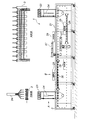
図1は、粉体焼付け塗装装置1の全体的な構成図である。
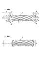
この装置で処理される被塗物としてのアルミダイカスト品3の一例は、図2に示すバッテリー用の絶縁カートリッジの一部をなすものであり、矩形プレート状で多数の装着孔5が形成されている。
このアルミダイカスト品3の長手方向両端側には複数のボルト孔7が設けられており、この部分のマスキングが必要になっている。
<Powder baking coating equipment>
An example of the powder baking coating apparatus 1 for carrying out the above-mentioned insulating coating method is shown below.
FIG. 1 is an overall configuration diagram of the powder baking coating apparatus 1.
An example of the aluminum die-
A plurality of bolt holes 7 are provided on both ends in the longitudinal direction of the aluminum die-
符号9はマスキング治具を示す。このマスキング治具9は、銅切板をU字状に折り曲げて成形した受け部11を備えており、受け部11の外側には銅パイプ製の支え軸13が連結されている。この受け部11の包持側には、テフロン(登録商標)板を同様にU字状に折り曲げて成形した絶縁性の包持部15が一体に取り付けられて全体としてU字状をなしている。この一体化された受け部11と包持部15には、複数の連通孔17が設けられている。
符号19は上記とは別のマスキング治具を示す。このマスキング治具19は支え軸13を設けられていないだけで、その他の構成はマスキング治具9と同じになっている。
アルミダイカスト品3の長手方向両端側からそれぞれマスキング治具9、19をスライド移動させアルミダイカスト品3を挟み込む。その状態では、連通孔17がアルミダイカスト品3のボルト孔7と連通しているので、そこにボルト20を通して締めることで、連結させる。
なお、図2は、ボルト孔7と連通孔17は、孔縁が視認し易くなるよう、孔縁の輪郭線が実線で示されている。
The masking jigs 9 and 19 are slid from both ends of the aluminum die-
In FIG. 2, the bolt hole 7 and the
アルミダイカスト品3はこのマスキング治具9、19を装着した状態で、粉体焼付け塗装に供される。
粉体焼付け塗装装置1には、環状軌道の搬送ライン21に、塗装部23が二か所、加熱部25が二か所、エア吹き落とし部27が二か所設けられており、第1コートベーク部(塗装部23〜加熱部25〜エア吹き落とし部27)〜第2コートベーク部(塗装部23〜加熱部25〜エア吹き落とし部27)の順に配置されており、そこを通過するときに各処理が施される。
従って、アルミダイカスト品3は搬送ライン21を一周すると、2コート2ベークが完了したことになる。
The aluminum die-
In the powder baking coating apparatus 1, the
Therefore, when the aluminum die-
搬送ライン21では、マスキング治具9の支え軸13が搬送ハンガー(図示省略)に取り付けられ、アルミダイカスト品3の板面が上下方向を向く姿勢で搬送される。
塗装部23では、塗装ガン24が下側を向いており、アルミダイカスト品3がその下方を通過するようになっている。アルミダイカスト品3はそこで軸周りに回転するので両板面及び両板部の表面に粉体塗料が万遍無く吹き付けられ塗着する。なお、部室内はバキュームを使用して負圧に維持され、且つイオナイザーが併用されており、塗装装置に粉体塗料が付着しないようになっている。
加熱部25では、平面状ワークコイル26、26で上下から挟むようになっており、ワークコイル26への高周波電源の供給により、アルミダイカスト品3が誘導加熱される。
エア吹き落とし部27では、エアを吹き付けて、マスキング治具9、19上に乗っている余分な粉体塗料が落とされて清掃される。
ベークの後には、次の処理部まで、搬送ライン21上に間隔が開けられており、そこで放冷される。すなわち、冷却部29として働く。
In the
In the
The
In the air blow-
After the bake, there is an interval on the
以下の実施条件で、エポキシ樹脂を主成分とする粉体塗料を使用し、上記の装置1を用いて、アルミダイカスト品3の絶縁塗装を行った。
なお、加熱部は、昇温速度は大きく、約150秒で240℃まで昇温できるものとした。使用した粉体塗料は、高周波誘導加熱方式に適用する場合には、220℃を最適焼付け温度とし、そのプラスマイナス20℃以内が標準焼付け温度の範囲となっている。
(実施条件1)
第1コートベーク部では、塗装無しで、260℃まで加熱した後冷却して、空焼き効果を狙った。
第2コートベーク部では、120〜150μmに塗着し、220℃まで加熱した後、清掃し、冷却して処理を終了した。なお、粉体塗料の流動性を良くするため、他の実施条件よりも細かくした粉体塗料を使用した。
Under the following implementation conditions, a powder coating material containing an epoxy resin as a main component was used, and the aluminum die-
It should be noted that the heating unit has a high heating rate and can raise the temperature to 240 ° C. in about 150 seconds. When applied to the high-frequency induction heating method, the powder coating material used has an optimum baking temperature of 220 ° C., and the standard baking temperature is within plus or minus 20 ° C.
(Implementation condition 1)
The first coat bake portion was heated to 260 ° C. and then cooled without painting to aim for an air-baking effect.
In the second coat bake portion, the coating was applied to 120 to 150 μm, heated to 220 ° C., cleaned, cooled, and the treatment was completed. In addition, in order to improve the fluidity of the powder coating material, a powder coating material finer than other implementation conditions was used.
(実施条件2)
第1コートベーク部では、50〜80μmに塗着し、230℃まで加熱した後、清掃し、冷却して処理を終了した。
第2コートベーク部では、80〜100μmに塗着し、230℃まで加熱した後、清掃し、冷却して処理を終了した。
(実施条件3)
第1コートベーク部では、50〜80μmに塗着し、240℃まで加熱した後、清掃し、冷却して処理を終了した。
第2コートベーク部では、60〜100μmに塗着し、220℃まで加熱した後、清掃し、冷却して処理を終了した。
(Implementation condition 2)
In the first coat bake portion, the coating was applied to 50 to 80 μm, heated to 230 ° C., cleaned, cooled, and the treatment was completed.
In the second coat bake portion, the coating was applied to 80 to 100 μm, heated to 230 ° C., cleaned, cooled, and the treatment was completed.
(Implementation condition 3)
In the first coat bake portion, the coating was applied to 50 to 80 μm, heated to 240 ° C., cleaned, cooled, and the treatment was completed.
In the second coat bake portion, the coating was applied to 60 to 100 μm, heated to 220 ° C., cleaned, cooled, and the treatment was completed.
(実施条件4)
第1コートベーク部では、50〜80μmに塗着し、210℃まで加熱した後、清掃し、冷却して処理を終了した。
第2コートベーク部では、60〜100μmに塗着し、240℃まで加熱した後、清掃し、冷却して処理を終了した。
(実施条件5)
第1コートベーク部では、40〜50μmに塗着し、210℃まで加熱した後、清掃し、冷却して処理を終了した。
第2コートベーク部では、100〜120μmに塗着し、240℃まで加熱した後、清掃し、冷却して処理を終了した。
(Implementation condition 4)
In the first coat bake portion, the coating was applied to 50 to 80 μm, heated to 210 ° C., cleaned, cooled, and the treatment was completed.
In the second coat bake portion, the coating was applied to 60 to 100 μm, heated to 240 ° C., cleaned, cooled, and the treatment was completed.
(Implementation condition 5)
In the first coat bake portion, the coating was applied to 40 to 50 μm, heated to 210 ° C., cleaned, cooled, and the treatment was completed.
In the second coat bake portion, the coating was applied to 100 to 120 μm, heated to 240 ° C., cleaned, cooled, and the treatment was completed.
(実施条件6)
第1コートベーク部では、70〜120μmに塗着し、240℃まで加熱した後、清掃し、冷却して処理を終了した。
第2コートベーク部では、30〜70μmに塗着し、220℃まで加熱した後、清掃し、冷却して処理を終了した。
(Implementation condition 6)
In the first coat bake portion, the coating was applied to 70 to 120 μm, heated to 240 ° C., cleaned, cooled, and the treatment was completed.
In the second coat bake portion, the coating was applied to 30 to 70 μm, heated to 220 ° C., cleaned, cooled, and the treatment was completed.
この条件のうち、(実施条件1)では、塗膜に多数のピンホールが認められ、絶縁効果は、全く期待できなかった。
(実施条件2)〜(実施条件5)では、ピンホールは殆ど認められず、絶縁効果も期待できた。
(実施条件6)では、ピンホールは確認できず、圧延材に処理した場合に匹敵する表面平滑性が得られ、格段の絶縁効果が期待できた。
Among these conditions, under (implementation condition 1), a large number of pinholes were observed in the coating film, and no insulating effect could be expected.
In (Implementation condition 2) to (Implementation condition 5), almost no pinholes were observed, and an insulating effect could be expected.
Under (Implementation condition 6), pinholes could not be confirmed, surface smoothness comparable to that when the rolled material was processed was obtained, and a remarkable insulating effect could be expected.
1…粉体焼付け塗装装置 3…アルミダイカスト品 5…装着孔 7…ボルト孔
9…マスキング治具 11…受け部 13…支え軸 15…包持部
17…連通孔 19…別のマスキング治具 20…ボルト
21…搬送ライン 23…塗装部 24…塗装ガン
25…加熱部 26…ワークコイル 27…エア吹き落とし部
1 ... Powder
Claims (2)
前記第2の粉体塗料の焼付け温度を、標準焼付け温度にし、前記第1の粉体塗料の焼付け温度を、前記第2の粉体塗料の焼付け温度よりも20℃高い温度にし、
前記第1の粉体塗料と前記第2の粉体塗料を同じ種類のものとし、
前記第1の粉体塗料を、前記第2の粉体塗料よりも厚く塗着することを特徴とする絶縁塗装方法。 The first powder paint was applied to the aluminum die-cast product to be coated by an electrostatic method, and then heated and melted by baking and drying by a high-frequency induction heating method, and then cooled to form a powder coating film on the lower side. Later, a second powder paint is applied onto it by an electrostatic method, and by baking and drying by a high-frequency induction heating method, it is heated and melted and then cooled to form an upper powder coating, thereby imparting insulation. It is an insulation coating method for aluminum die-cast products.
The baking temperature of the second powder coating material is set to the standard baking temperature, and the baking temperature of the first powder coating material is set to a temperature 20 ° C. higher than the baking temperature of the second powder coating material.
The first powder coating material and the second powder coating material are of the same type.
An insulating coating method comprising applying the first powder coating material thicker than the second powder coating material.
第1の粉体塗料を70〜120μm、第2の粉体塗料を30〜70μmの厚さでそれぞれ塗着することを特徴とする絶縁塗装方法。 In the method for insulating and coating an aluminum die-cast product according to claim 1.
An insulating coating method characterized in that the first powder coating material is applied to a thickness of 70 to 120 μm and the second powder coating material is applied to a thickness of 30 to 70 μm.
Priority Applications (1)
| Application Number | Priority Date | Filing Date | Title |
|---|---|---|---|
| JP2017082865A JP6846741B2 (en) | 2017-04-19 | 2017-04-19 | Insulation coating method for aluminum die-cast products |
Applications Claiming Priority (1)
| Application Number | Priority Date | Filing Date | Title |
|---|---|---|---|
| JP2017082865A JP6846741B2 (en) | 2017-04-19 | 2017-04-19 | Insulation coating method for aluminum die-cast products |
Publications (2)
| Publication Number | Publication Date |
|---|---|
| JP2018176112A JP2018176112A (en) | 2018-11-15 |
| JP6846741B2 true JP6846741B2 (en) | 2021-03-24 |
Family
ID=64280472
Family Applications (1)
| Application Number | Title | Priority Date | Filing Date |
|---|---|---|---|
| JP2017082865A Active JP6846741B2 (en) | 2017-04-19 | 2017-04-19 | Insulation coating method for aluminum die-cast products |
Country Status (1)
| Country | Link |
|---|---|
| JP (1) | JP6846741B2 (en) |
Families Citing this family (2)
| Publication number | Priority date | Publication date | Assignee | Title |
|---|---|---|---|---|
| CN114149720A (en) * | 2021-11-17 | 2022-03-08 | 浙江富佰特材科技有限公司 | Electrostatic spraying high-corrosion-resistance insulating steel rail |
| KR102447942B1 (en) * | 2022-04-25 | 2022-09-27 | 주식회사 동우씨제이 | Powder coating method for die-casting products |
-
2017
- 2017-04-19 JP JP2017082865A patent/JP6846741B2/en active Active
Also Published As
| Publication number | Publication date |
|---|---|
| JP2018176112A (en) | 2018-11-15 |
Similar Documents
| Publication | Publication Date | Title |
|---|---|---|
| US7455881B2 (en) | Methods for coating a magnesium component | |
| JP2013500154A (en) | Method and apparatus for applying at least one anticorrosive liquid coating comprising metal particles to a workpiece. | |
| JP6846741B2 (en) | Insulation coating method for aluminum die-cast products | |
| CN106141181A (en) | Increasing material on 3-D component manufactures | |
| JPH08246943A (en) | Manufacture of engine block in which cylinder hole wall is coated | |
| EP2688708B1 (en) | Method for repairing an aluminium alloy component | |
| CN104451524B (en) | A kind of NiCrBSi coating production for minor diameter ball | |
| JP2001503478A (en) | Method of applying inorganic coating to electrical conductor | |
| CN102756515B (en) | A kind of pottery covers aluminium base and preparation method thereof | |
| CN108607796A (en) | A kind of preparation method of Electrolyzed Processing cathode insulation coating | |
| CN107805809A (en) | A kind of automobile die surface coating renovation technique | |
| CN107127122A (en) | A kind of workmanship of spraying plastics flow | |
| US20160083814A1 (en) | High temperature oxidation-resistant coated steel plate and hot stamping method thereof | |
| CN106319420A (en) | Method for improving bonding strength of thermal spraying ceramic coating on 7075 aluminum alloy surface | |
| RU2621088C1 (en) | Method for producing coating on steel plate | |
| JP3356960B2 (en) | Spraying method of cast iron tube | |
| US20200173005A1 (en) | Method of coating a workpiece | |
| CN106269439B (en) | The insulation protection method of chrome-plating clamp | |
| JP2932618B2 (en) | Casting pin for aluminum casting | |
| JPH01246352A (en) | Metal thermal spraying method | |
| GB2478641A (en) | Masking means and methods of use | |
| KR101637500B1 (en) | Method for plating rust-proofing film on ball stud | |
| JP2012026013A (en) | Component for film-forming apparatus and method for removing film adhered to the same | |
| CN108070691A (en) | A kind of process of surface treatment of auto parts and components | |
| JP2014019878A (en) | Heat treatment method for malleable cast iron, and casting |
Legal Events
| Date | Code | Title | Description |
|---|---|---|---|
| RD01 | Notification of change of attorney |
Free format text: JAPANESE INTERMEDIATE CODE: A7426 Effective date: 20170508 |
|
| A521 | Request for written amendment filed |
Free format text: JAPANESE INTERMEDIATE CODE: A821 Effective date: 20170508 |
|
| A621 | Written request for application examination |
Free format text: JAPANESE INTERMEDIATE CODE: A621 Effective date: 20190611 |
|
| A977 | Report on retrieval |
Free format text: JAPANESE INTERMEDIATE CODE: A971007 Effective date: 20200713 |
|
| A131 | Notification of reasons for refusal |
Free format text: JAPANESE INTERMEDIATE CODE: A131 Effective date: 20200818 |
|
| A521 | Request for written amendment filed |
Free format text: JAPANESE INTERMEDIATE CODE: A523 Effective date: 20201008 |
|
| TRDD | Decision of grant or rejection written | ||
| A01 | Written decision to grant a patent or to grant a registration (utility model) |
Free format text: JAPANESE INTERMEDIATE CODE: A01 Effective date: 20210208 |
|
| A61 | First payment of annual fees (during grant procedure) |
Free format text: JAPANESE INTERMEDIATE CODE: A61 Effective date: 20210217 |
|
| R150 | Certificate of patent or registration of utility model |
Ref document number: 6846741 Country of ref document: JP Free format text: JAPANESE INTERMEDIATE CODE: R150 |
|
| R250 | Receipt of annual fees |
Free format text: JAPANESE INTERMEDIATE CODE: R250 |