JP6845583B2 - A set with equipment for spinal surgery, belonging guide sleeves, and guide sleeves - Google Patents
A set with equipment for spinal surgery, belonging guide sleeves, and guide sleeves Download PDFInfo
- Publication number
- JP6845583B2 JP6845583B2 JP2018508211A JP2018508211A JP6845583B2 JP 6845583 B2 JP6845583 B2 JP 6845583B2 JP 2018508211 A JP2018508211 A JP 2018508211A JP 2018508211 A JP2018508211 A JP 2018508211A JP 6845583 B2 JP6845583 B2 JP 6845583B2
- Authority
- JP
- Japan
- Prior art keywords
- guide sleeve
- long sides
- sides
- guide
- sleeve
- Prior art date
- Legal status (The legal status is an assumption and is not a legal conclusion. Google has not performed a legal analysis and makes no representation as to the accuracy of the status listed.)
- Active
Links
- 238000001356 surgical procedure Methods 0.000 title claims description 22
- 230000007704 transition Effects 0.000 claims description 5
- 210000001519 tissue Anatomy 0.000 description 4
- 208000027418 Wounds and injury Diseases 0.000 description 2
- 230000006378 damage Effects 0.000 description 2
- 208000014674 injury Diseases 0.000 description 2
- 238000000034 method Methods 0.000 description 2
- 210000000988 bone and bone Anatomy 0.000 description 1
- 230000006835 compression Effects 0.000 description 1
- 238000007906 compression Methods 0.000 description 1
- 230000010339 dilation Effects 0.000 description 1
- 230000001771 impaired effect Effects 0.000 description 1
- 239000007943 implant Substances 0.000 description 1
- 210000003205 muscle Anatomy 0.000 description 1
- 210000005036 nerve Anatomy 0.000 description 1
- 230000037361 pathway Effects 0.000 description 1
- 239000007787 solid Substances 0.000 description 1
Images


Classifications
-
- A—HUMAN NECESSITIES
- A61—MEDICAL OR VETERINARY SCIENCE; HYGIENE
- A61F—FILTERS IMPLANTABLE INTO BLOOD VESSELS; PROSTHESES; DEVICES PROVIDING PATENCY TO, OR PREVENTING COLLAPSING OF, TUBULAR STRUCTURES OF THE BODY, e.g. STENTS; ORTHOPAEDIC, NURSING OR CONTRACEPTIVE DEVICES; FOMENTATION; TREATMENT OR PROTECTION OF EYES OR EARS; BANDAGES, DRESSINGS OR ABSORBENT PADS; FIRST-AID KITS
- A61F2/00—Filters implantable into blood vessels; Prostheses, i.e. artificial substitutes or replacements for parts of the body; Appliances for connecting them with the body; Devices providing patency to, or preventing collapsing of, tubular structures of the body, e.g. stents
- A61F2/02—Prostheses implantable into the body
- A61F2/30—Joints
- A61F2/46—Special tools or methods for implanting or extracting artificial joints, accessories, bone grafts or substitutes, or particular adaptations therefor
- A61F2/4603—Special tools or methods for implanting or extracting artificial joints, accessories, bone grafts or substitutes, or particular adaptations therefor for insertion or extraction of endoprosthetic joints or of accessories thereof
- A61F2/4611—Special tools or methods for implanting or extracting artificial joints, accessories, bone grafts or substitutes, or particular adaptations therefor for insertion or extraction of endoprosthetic joints or of accessories thereof of spinal prostheses
-
- A—HUMAN NECESSITIES
- A61—MEDICAL OR VETERINARY SCIENCE; HYGIENE
- A61B—DIAGNOSIS; SURGERY; IDENTIFICATION
- A61B17/00—Surgical instruments, devices or methods, e.g. tourniquets
- A61B17/56—Surgical instruments or methods for treatment of bones or joints; Devices specially adapted therefor
- A61B17/58—Surgical instruments or methods for treatment of bones or joints; Devices specially adapted therefor for osteosynthesis, e.g. bone plates, screws, setting implements or the like
- A61B17/68—Internal fixation devices, including fasteners and spinal fixators, even if a part thereof projects from the skin
- A61B17/70—Spinal positioners or stabilisers ; Bone stabilisers comprising fluid filler in an implant
- A61B17/7071—Implants for expanding or repairing the vertebral arch or wedged between laminae or pedicles; Tools therefor
-
- A—HUMAN NECESSITIES
- A61—MEDICAL OR VETERINARY SCIENCE; HYGIENE
- A61F—FILTERS IMPLANTABLE INTO BLOOD VESSELS; PROSTHESES; DEVICES PROVIDING PATENCY TO, OR PREVENTING COLLAPSING OF, TUBULAR STRUCTURES OF THE BODY, e.g. STENTS; ORTHOPAEDIC, NURSING OR CONTRACEPTIVE DEVICES; FOMENTATION; TREATMENT OR PROTECTION OF EYES OR EARS; BANDAGES, DRESSINGS OR ABSORBENT PADS; FIRST-AID KITS
- A61F2/00—Filters implantable into blood vessels; Prostheses, i.e. artificial substitutes or replacements for parts of the body; Appliances for connecting them with the body; Devices providing patency to, or preventing collapsing of, tubular structures of the body, e.g. stents
- A61F2/02—Prostheses implantable into the body
- A61F2/30—Joints
- A61F2/44—Joints for the spine, e.g. vertebrae, spinal discs
- A61F2/4455—Joints for the spine, e.g. vertebrae, spinal discs for the fusion of spinal bodies, e.g. intervertebral fusion of adjacent spinal bodies, e.g. fusion cages
- A61F2/447—Joints for the spine, e.g. vertebrae, spinal discs for the fusion of spinal bodies, e.g. intervertebral fusion of adjacent spinal bodies, e.g. fusion cages substantially parallelepipedal, e.g. having a rectangular or trapezoidal cross-section
-
- A—HUMAN NECESSITIES
- A61—MEDICAL OR VETERINARY SCIENCE; HYGIENE
- A61B—DIAGNOSIS; SURGERY; IDENTIFICATION
- A61B17/00—Surgical instruments, devices or methods, e.g. tourniquets
- A61B17/02—Surgical instruments, devices or methods, e.g. tourniquets for holding wounds open; Tractors
- A61B17/025—Joint distractors
- A61B2017/0256—Joint distractors for the spine
-
- A—HUMAN NECESSITIES
- A61—MEDICAL OR VETERINARY SCIENCE; HYGIENE
- A61F—FILTERS IMPLANTABLE INTO BLOOD VESSELS; PROSTHESES; DEVICES PROVIDING PATENCY TO, OR PREVENTING COLLAPSING OF, TUBULAR STRUCTURES OF THE BODY, e.g. STENTS; ORTHOPAEDIC, NURSING OR CONTRACEPTIVE DEVICES; FOMENTATION; TREATMENT OR PROTECTION OF EYES OR EARS; BANDAGES, DRESSINGS OR ABSORBENT PADS; FIRST-AID KITS
- A61F2/00—Filters implantable into blood vessels; Prostheses, i.e. artificial substitutes or replacements for parts of the body; Appliances for connecting them with the body; Devices providing patency to, or preventing collapsing of, tubular structures of the body, e.g. stents
- A61F2/02—Prostheses implantable into the body
- A61F2/30—Joints
- A61F2002/30001—Additional features of subject-matter classified in A61F2/28, A61F2/30 and subgroups thereof
- A61F2002/30108—Shapes
- A61F2002/3011—Cross-sections or two-dimensional shapes
- A61F2002/30112—Rounded shapes, e.g. with rounded corners
- A61F2002/30125—Rounded shapes, e.g. with rounded corners elliptical or oval
-
- A—HUMAN NECESSITIES
- A61—MEDICAL OR VETERINARY SCIENCE; HYGIENE
- A61F—FILTERS IMPLANTABLE INTO BLOOD VESSELS; PROSTHESES; DEVICES PROVIDING PATENCY TO, OR PREVENTING COLLAPSING OF, TUBULAR STRUCTURES OF THE BODY, e.g. STENTS; ORTHOPAEDIC, NURSING OR CONTRACEPTIVE DEVICES; FOMENTATION; TREATMENT OR PROTECTION OF EYES OR EARS; BANDAGES, DRESSINGS OR ABSORBENT PADS; FIRST-AID KITS
- A61F2/00—Filters implantable into blood vessels; Prostheses, i.e. artificial substitutes or replacements for parts of the body; Appliances for connecting them with the body; Devices providing patency to, or preventing collapsing of, tubular structures of the body, e.g. stents
- A61F2/02—Prostheses implantable into the body
- A61F2/30—Joints
- A61F2/46—Special tools or methods for implanting or extracting artificial joints, accessories, bone grafts or substitutes, or particular adaptations therefor
- A61F2002/4687—Mechanical guides for implantation instruments
Description
本発明は、少なくとも1つの案内スリーブと少なくとも1つの拡張器とを備え、該拡張器の外輪郭は案内スリーブの内輪郭に対応する脊椎手術用の装置、並びに脊椎手術のための導入セットに関するものである。さらに本発明は、とりわけセットの一部としての脊椎手術用の所属の案内スリーブ、および案内スリーブとこの案内スリーブによって位置決され、そのような案内スリーブによる脊椎手術のための椎間ケージと少なくとも1つの拡張器とから成る脊椎手術用のセット、並びに案内スリーブとこの案内スリーブによって椎間領域に取り付けるべき椎間ケージとから成るセットに関する The present invention comprises at least one guide sleeve and at least one dilator, wherein the outer contour of the dilator relates to a device for spinal surgery corresponding to the inner contour of the guide sleeve, as well as an introductory set for spinal surgery. Is. Furthermore, the present invention is positioned by a dedicated guide sleeve for spinal surgery, and a guide sleeve and this guide sleeve, among other things, and an intervertebral cage for spinal surgery with such a guide sleeve and at least one. Regarding a set for spinal surgery consisting of two dilators, and a set consisting of a guide sleeve and an intervertebral cage to be attached to the facet area by this guide sleeve.
脊椎外科では、患者の背中を多大に切開し、筋肉を切断することにより手術すべき領域の脊椎を露出させる従来の手術法が、経皮的な脊椎手術法によってますます置き換えられている。器具を皮膚および脊椎ないし椎骨の前にある組織を通して導入するための経路を形成し、並びにそのような機器による経皮的作業を可能にするために、十分な内径、したがって断面を有する案内または作業スリーブが導入される。このスリーブは簡単にはそれとして導入することができない。そうではなく皮膚およびその下の組織を、スタイレットおよびこれを密に取り囲む中空針から成る細いニードルセットによってまず突き通す。このスタイレットと中空針は両方とも遠位が先細である、すなわち尖っている(ジャムシディ針)。引き続きスタイレットが中空針から除去され、この中空針を通して案内ワイヤが椎間板腔または椎間腔まで案内される。次に中空針が除去され、案内ワイヤを介して第1の拡張器が導入される。この拡張器を介してそれぞれさらなる拡張器が導入され、これらさらなる拡張器の内径は先行して導入された拡張器の外径に密に適合している。これらの拡張器の端部は円錐形に先細である。このことは、最後の拡張器を介して案内または作業スリーブを導入することができるまで行われる。そしてこのスリーブから案内ワイヤと拡張器が除去され、このスリーブの内腔を通して器具等を導入することにより、およびこれらの器具を介して、または椎間ケージ(椎体間ケージ)を椎間腔へ導入することにより外科医は作業することができる。前記全てのステップおよびさらなるステップもX線観察の下で行われる。 In spinal surgery, percutaneous spinal surgery is increasingly replacing the traditional surgical procedure of making a large incision in the patient's back and cutting the muscles to expose the spine in the area to be operated on. Guidance or work with sufficient inner diameter, and thus cross section, to form a pathway for introducing the device through the skin and tissue in front of the spine or vertebrae, and to allow percutaneous work with such devices. A sleeve is introduced. This sleeve cannot be easily introduced as it. Instead, the skin and the underlying tissue are first pierced by a thin needle set consisting of a stylet and a hollow needle that closely surrounds it. Both the stylet and the hollow needle are tapered or pointed (jamsidi needle) at the distal end. The stylet is subsequently removed from the hollow needle and the guide wire is guided through the hollow needle to the disc or intervertebral space. The hollow needle is then removed and a first dilator is introduced via the guide wire. Each additional dilator is introduced through this dilator, and the inner diameter of these additional dilators closely matches the outer diameter of the previously introduced dilator. The ends of these dilators are tapered in a conical shape. This is done until the guide or work sleeve can be introduced via the last dilator. Guide wires and dilators are then removed from the sleeve, and by introducing instruments, etc. through the lumen of the sleeve, and through these instruments, or through the intervertebral cage (interbody cage) into the intervertebral space. The introduction allows the surgeon to work. All the steps and further steps are also performed under X-ray observation.
拡張器およびとりわけ作業または案内スリーブは、これまで通常はシリンダ状に構成されている。しかしとりわけ椎間ケージを導入する場合には、開放手術と比較して経皮的処置だけによって患者の負荷を格段に低減することはまだ望まれていないことが判明した。なぜならとりわけケージの側方断面寸法が大きく、したがって従来のシリンダ状の案内スリーブの直径も同様に大きくなければならないからである。 The dilator and, above all, the work or guide sleeve have traditionally been constructed in the form of a cylinder, usually in the form of a cylinder. However, it has been found that it is not yet desired to significantly reduce the burden on patients by percutaneous treatment alone as compared with open surgery, especially when introducing an intervertebral cage. This is because the lateral cross-sectional dimensions of the cage are particularly large, and therefore the diameter of the conventional cylindrical guide sleeve must be large as well.
したがって本発明の基礎とする課題は、使用の際に経皮的脊椎手術における患者の負荷をさらに格段に低減することのできる脊椎手術用の装置および案内スリーブ、並びに案内スリーブと椎間ケージとから成るセットを創出することである。 Therefore, the underlying task of the present invention is from spinal surgery devices and guide sleeves, as well as guide sleeves and intervertebral cages, which can significantly reduce the patient's burden in percutaneous spine surgery during use. Is to create a set of.
本発明によれば前記課題はまず、冒頭に述べた形式の脊柱手術用装置によって解決され、この装置は非シリンダ状の外套を特徴とする。 According to the present invention, the above problems are first solved by a spinal surgery device of the type described at the beginning, which is characterized by a non-cylinder mantle.
前記課題を解決するために本発明はさらに、非シリンダ状の外套を特徴とする案内スリーブを提案する。前記課題を解決するために、案内スリーブとこの案内スリーブによって導入し配置すべき椎間ケージとから成る脊柱手術用のセットも提案され、このセットは、案内スリーブの内腔が椎間ケージの最大断面輪郭に適合されていることを特徴とする。 To solve the above problems, the present invention further proposes a guide sleeve characterized by a non-cylindrical cloak. To solve the above problems, a set for spinal surgery consisting of a guide sleeve and an intervertebral cage to be introduced and placed by the guide sleeve has also been proposed, in which the lumen of the guide sleeve is the maximum of the intervertebral cage. It is characterized in that it is adapted to the cross-sectional contour.
したがって導入セットとしても使用される本発明の装置は、前記形態に構成された少なくとも1つの案内スリーブと、少なくとも1つの、第1または最外の、拡張器(しかしこの拡張器は案内スリーブ内部に配置されているか、あるいは案内スリーブを介して導入される)とを有し、この拡張器の外輪郭は案内スリーブの内腔に適合されている。 Thus, the device of the invention, which is also used as an introductory set, has at least one guide sleeve configured as described above and at least one first or outermost dilator (but this dilator is inside the guide sleeve). The outer contour of this dilator is adapted to the lumen of the guide sleeve (placed or introduced via a guide sleeve).
本装置およびこの案内スリーブ自体並びにこれを含む埋め込みセットの本発明による構成によって、このような案内スリーブにより経皮的手術が行われる患者、とりわけ椎間ケージの取り付けが行われる患者の負荷が格段に低減されることが達成される。なぜなら案内スリーブの高さが従来のシリンダ状の案内スリーブと比較して格段に低減されているからである。したがって高さ方向(すなわち脊椎の伸長方向)における拡張は格段に小さくなり、露出される神経根に対する圧迫の危険性も小さくなる。 The present invention of the device and the guide sleeve itself and the implantable set including the guide sleeve significantly imposes a load on patients undergoing percutaneous surgery with such guide sleeves, especially those undergoing intervertebral cage attachment. It is achieved to be reduced. This is because the height of the guide sleeve is significantly reduced as compared with the conventional cylinder-shaped guide sleeve. Therefore, the dilation in the height direction (ie, the extension direction of the spine) is significantly reduced, and the risk of compression on the exposed nerve roots is also reduced.
本発明の好ましい一発展形態では、案内スリーブにおいて互いに対向する2つの長辺は、これらを接続する短辺の幅よりも大きい幅を有する。このことはとりわけ椎間板腔の高さが小さい場合に当てはまる。さらに長辺の一方は平坦で良く、および/または長辺の一方は外に向かって凸状に湾曲しても良く、その場合はとりわけ11から12.5mmの曲率半径を有する。さらに本発明の好ましい形態では、長辺と短辺の間の移行部の曲率の角度は3から4.5mmの間である。 In a preferred evolution of the invention, the two long sides of the guide sleeve facing each other have a width greater than the width of the short side connecting them. This is especially true when the height of the disc cavity is small. Further, one of the long sides may be flat and / or one of the long sides may be curved outward in a convex manner, in which case it has a radius of curvature of 11 to 12.5 mm in particular. Further, in a preferred embodiment of the present invention, the angle of curvature of the transition portion between the long side and the short side is between 3 and 4.5 mm.
本発明の非常に好ましい一発展形態では案内スリーブの短辺は遠位に、長辺を超えて突き出る突起を有する。ここでとりわけ突起は、その自由端部に向かって先細であり、自由端部において丸められており、および/または短辺は長辺よりも大きな厚さを有し、好ましくは長辺の厚さは0.8mmから1.2mmであり、および/または短辺の厚さは1.2mmから1.7mm超である。 In a highly preferred evolution of the invention, the short side of the guide sleeve has a distal protrusion that protrudes beyond the long side. Here, among other things, the protrusions are tapered towards their free end, rounded at the free end, and / or the short side has a thickness greater than the long side, preferably the thickness of the long side. Is from 0.8 mm to 1.2 mm, and / or the thickness of the short side is from 1.2 mm to over 1.7 mm.
案内スリーブおよびこれにその外輪郭が直接的に適合された拡張器から成る導入セットの改善形態では、とりわけ拡張器の内腔がシリンダ状に構成されている。これにより、装填されている案内ワイヤを介して、あるいは重なり合って皮膚と組織を通り脊柱の手術箇所まで最初に導入されるさらなる内側の拡張器を、相変わらず公知のようにシリンダ状の輪郭により構成できることが達成される。しかもこのことが患者の負荷の増大に繋がることはなく、あるいは案内スリーブと案内スリーブが直接的に導入される最後の拡張器の本発明による構成により達成された負荷の小さいことが損なわれることはない。 In an improved form of the introduction set consisting of a guide sleeve and an expander to which its outer contour is directly adapted, the lumen of the expander is particularly cylindrical. This allows additional medial dilators to be initially introduced through the skin and tissue through the loaded guide wires or overlapping to the surgical site of the spinal column, as is still known, with a cylindrical contour. Is achieved. Moreover, this does not lead to an increase in patient load, or the small load achieved by the present invention configuration of the guide sleeve and the last dilator into which the guide sleeve is directly introduced is impaired. Absent.
さらに好ましい構成では、スリーブおよび/または拡張器は、それらの長手軸に対して横方向に延在する溝を、それらの外側の近位領域に、とりわけそれらの短辺に有する。これらの溝は、指に対して良好な把持を保証するために、または工具をスリーブないし拡張器から引き抜くために用いられる。一発展形態では、近位の歯/エッジ領域に直径方向に対向する開口部が設けられている。
In a more preferred configuration, the sleeves and / or dilators have grooves that extend laterally to their longitudinal axis in their outer proximal regions, especially on their short sides. These grooves are used to ensure good grip on the fingers or to pull the tool out of the sleeve or dilator. In one evolution, the proximal tooth / edge region is provided with diametrically opposed openings.
最後に案内スリーブと椎間ケージとから成る脊椎手術用の埋め込みセットでは、案内スリーブが、好ましくは前記形態の1つまたは複数に対応して構成されている。 Finally, in a spinal surgery implant set consisting of a guide sleeve and an intervertebral cage, the guide sleeve is preferably configured for one or more of the above forms.
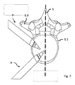
2つの椎骨の間の中間空間(椎間板腔)への本発明の装置によるアクセスは、後方側方からも、前方側方からも可能である。すなわち好ましくは、それぞれ−中央−矢状面に対して、あるいはこの面にある−水平−矢状軸に対してそれぞれ30゜から60゜、好ましくは40°から50°のアクセス角により、それぞれ側方後方ないし側方前方の上方からアクセスされる。これは図7に示されている。ここで後方側方からのアクセスは、好ましくは脊椎の棘突起の外側側面に沿って行うことができる。 Access by the device of the present invention to the intermediate space (disc cavity) between two vertebrae is possible from both posterior and anterior lateral. That is, preferably with access angles of 30 ° to 60 °, preferably 40 ° to 50 °, respectively-to the central-sagittal plane, or to the-horizontal-sagittal axis on this plane, respectively. It is accessed from above the rear or front of the side. This is shown in FIG. Here, posterior lateral access can preferably be along the lateral aspect of the spinous processes of the spine.
本発明のさらなる利点および特徴は特許請求の範囲および以下の説明から明らかであり、以下では本発明の実施例を図面に基づき詳細に説明する。 Further advantages and features of the present invention will be apparent from the claims and the following description, and examples of the present invention will be described in detail below with reference to the drawings.
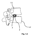
椎間板損傷部を部分的に、とりわけ完全に除去しなければならない椎間板損傷の場合、該当する椎間板に隣接する椎骨1.1,1.2の間で脊柱を安定させるために少なくとも1つの椎間ケージ2(椎体間ケージ)が使用される。 For disc injuries where the disc injury must be partially, especially completely removed, at least one intervertebral cage to stabilize the spinal column between the vertebrae 1.1 and 1.2 adjacent to the disc in question. 2 (intervertebral cage) is used.
椎間ケージ2は、異なる輪郭を有することができる。図2に例として斜視図に示すようなケージ2が適することが判明している。このようなケージは、安定した外側フレーム2.1と内側の多孔性、格子状または網状の構造体2.2を有し、この構造体は、隣接する椎骨1.1,1.2の骨がこの構造体へ成長することを許容し、これにより堅固な接続が創出される。
The
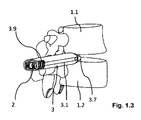
理解されるようにケージは、長手方向にその遠位端部に向かって先細になっている。上側面2.3は、その幅にわたって凸状に比較的に大きな曲率半径により湾曲されている。これにより椎骨の相対位置を、ケージ2を介して適合することができる。これに対してケージの下側面は、(図2では見えない)ケージの下方の面であり、側壁のようにその幅ないし高さにわたって湾曲しておらず、少なくともほぼ平坦に構成されている。このような椎間ケージ2は、図1.1〜1.3から理解されるように、案内スリーブ3によって椎間領域ないし以前の椎間板腔に導入される。
As will be appreciated, the cage tapers longitudinally towards its distal end. The upper side surface 2.3 is curved over its width in a convex shape with a relatively large radius of curvature. This allows the relative position of the vertebrae to be matched via the
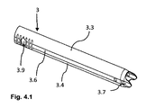
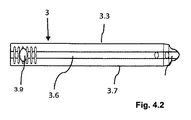
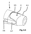
図3〜4.2から特に理解されるように、案内スリーブ3はその全長にわたって非シリンダ状の外套3.1と(内側)内腔3.2とを有し、この内腔は非シリンダ状の一定の内腔断面を備える。案内スリーブ3の内腔3.2の断面輪郭は、導入すべき椎間ケージ2(図2)の最大断面輪郭に、すなわちケージ2の近位端部の直前における椎間ケージの断面輪郭に十分な公差をもって適合されている。
As is particularly understood from FIGS. 3 to 4.2, the
案内スリーブ3の外套3.1ないし壁部は、実質的に互いに対向する上方と下方の長辺3.3,3.4並びにこれらを接続する短辺3.5,3.6は、本実施例では互いに対向する2つの短辺3.5,3.6を有する。
The outer cloak 3.1 to the wall portion of the
下方の長辺3.4は、実質的に、短辺3.5,3.6と同じように、内腔に向いた内側が平坦に構成されている。ここで長辺3.4と短辺3.5,3.6との間の移行部は鋭く角付けられておらず丸められている。下方の長辺3.4と短辺3.5,3.6との間の移行部の曲率半径は、ここでは4mmである。 The lower long side 3.4 is substantially flat on the inside facing the lumen, similar to the short sides 3.5 and 3.6. Here, the transition portion between the long side 3.4 and the short side 3.5, 3.6 is not sharply angled but rounded. The radius of curvature of the transition between the lower long side 3.4 and the short side 3.5, 3.6 is 4 mm here.
上方の長辺3.3は、案内スリーブ3の幅にわたって外に向かい凸状に湾曲して構成されている(すなわち平坦ではない)。上方の長辺の曲率半径は、ここでは12mmである。スリーブは、その近位の外側に横溝3.8と直径方向に対向する壁開口部3.9とを有する。この構成によって執刀医の指ないし工具に対する把持性が改善される。
The upper long side 3.3 is configured to be convexly curved outward over the width of the guide sleeve 3 (ie, not flat). The radius of curvature of the upper long side is 12 mm here. The sleeve has a lateral groove 3.8 and a diametrically opposed wall opening 3.9 on the outer side proximal to it. This configuration improves the surgeon's grip on fingers or tools.
同様に特に図3から分かるように、上方と下方の長辺3.3,3.4の壁厚は短辺3.5,3.6の壁厚よりも小さい。典型的に図示の実施例では上方と下方の長辺3.3,3.4の壁厚は約1mmであり、一方、短辺3.5,3.6の壁厚は約1.5mmである(図3の図示は拡大して示されている)。短辺3.5,3.6の遠位端部には−遠位−突起3.7が形成されている(図1,4.1〜4.2)。これらの突起は、一方では案内スリーブを2つの椎骨1.1と1.2の間で堅固に係留するために、他方では中間空間を拡張し、ケージ2を2つの椎骨1.1,1.2の間に導入することができるようにするために用いられる。突起3.7は短辺3.5,3.6の継続部を形成するから、突起3.7における短辺3.5,3.6の比較的に大きな壁厚によって比較的に高い安定性が付与され、したがってこれにより、案内スリーブ3の確実な係留と椎骨1.1,1.3の間の中間空間の拡張と言う課題をより確実に達成することができる。
Similarly, as can be seen particularly from FIG. 3, the wall thicknesses of the upper and lower long sides 3.3 and 3.4 are smaller than the wall thicknesses of the short sides 3.5 and 3.6. Typically, in the illustrated embodiment, the upper and lower long sides 3.3, 3.4 have a wall thickness of about 1 mm, while the short sides 3.5, 3.6 have a wall thickness of about 1.5 mm. Yes (the illustration in FIG. 3 is shown enlarged). -Distal-protrusions 3.7 are formed at the distal ends of the short sides 3.5 and 3.6 (Figs. 1, 4.1-4.2). These protrusions, on the one hand, anchor the guide sleeve tightly between the two vertebrae 1.1 and 1.2, and on the other hand, extend the intermediate space and
椎間ケージ2と案内スリーブ3は共に、脊椎手術のための1つのセットを形成する。それらの断面輪郭、すなわちケージ2の外輪郭と案内スリーブ3の内腔の輪郭は互いに適合している。
Both the
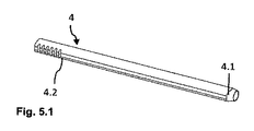
図5.1および5.2は拡張器4を示す。この拡張器は、案内スリーブがこの拡張器を介してスライドされる際に直接的に案内スリーブ3内に横たわる。したがって案内スリーブ3内に直接的に存在する拡張器4の外輪郭は、案内スリーブ3の内腔に小さな公差をもって適合されている。すなわち拡張器の下方外側の長辺は、その外側の短辺と同じように十分に平坦に構成されており、一方、上方外側の長辺は外に向かって凸状に湾曲している。拡張器4の外側の断面輪郭は、その長さの大部分にわたって一定であり、拡張器4の遠位端部4.1だけが円錐形に先細になっており、これはこの種の拡張器では通常のことである。
Figures 5.1 and 5.2 show the
拡張器4の内腔は、図5.1に示すように、特に拡張器4の右の遠位端部において、あるいは図6.3の左の近位端部においても分かるように、シリンダ状である。すなわち近位および遠位の入口開口部ないし出口開口部は円錐形である。拡張器4もその近位の外側に横溝4.3を有する。
The lumen of the
図6.1から6.5は、前に説明したのと同様の案内スリーブおよび図示の2つの拡張器を備える脊椎手術のための(導入)セットを示す。2つの拡張器は、前にとりわけ図5.1と5.2を参照して説明した拡張器4とさらなる拡張器5であり、このさらなる拡張器は拡張器4の内部に横たわり、あるいはさらなる拡張器の上に拡張器4が押し込まれる。
Figures 6.1-6.5 show a (introduction) set for spinal surgery with a guide sleeve similar to that previously described and the two dilators shown. The two dilators are the
図6.1から6.5に示したさらに内側にあるさらなる拡張器5は、拡張器4のシリンダ状の内輪郭に対応してシリンダ状の外輪郭を有し、同様にシリンダ状の内輪郭も有する。これはこの種の拡張器では通常のことである。一方で部材2,3、他方で部材3,4,5から成る2つの個別セットは、1つの全体的手術セットを形成する。
Further
2つの椎骨1.1,1.2の間の中間空間(椎間板腔)への本発明の装置によるアクセスは、後方側方Pからも、前方側方Aからも可能である。すなわち好ましくは、それぞれ−中央−矢状面Sに対して、あるいはこの面にある−水平−矢状軸に対してそれぞれ30°から60°、好ましくは40°から50°のアクセス角により、それぞれ側方後方ないし側方前方の上方からアクセスされる。これは図7に示されている。ここで後方側方からのアクセスは、好ましくは脊椎1.1の棘突起1.3の外側側面に沿って行うことができる。 Access to the intermediate space (disc space) between the two vertebrae 1.1 and 1.2 by the apparatus of the present invention is possible from both the posterior lateral P and the anterior lateral A. That is, preferably with an access angle of 30 ° to 60 °, preferably 40 ° to 50 °, respectively, with respect to the-center-sagittal plane S, or with respect to the-horizontal-sagittal axis on this plane, respectively. It is accessed from the side rear or the side front from above. This is shown in FIG. Here, posterior lateral access can preferably be along the lateral aspect of the spinous process 1.3 of the spine 1.1.
本発明の案内スリーブの本発明による非シリンダ状の構成によって、一方では案内スリーブによって椎間ケージを導入することができ、しかし他方では皮膚表面と椎間領域との間の案内スリーブ3の導入領域における患者の組織負荷を、とりわけ脊椎の伸長方向において可及的に小さくすることが達成される。なぜなら案内スリーブの本発明による構成により、その高さを従来の(円形断面を有する)案内スリーブよりも格段に低減することができるからである。
The non-cylindrical configuration of the guide sleeves of the present invention allows the intervertebral cage to be introduced by the guide sleeve on the one hand, but the introduction area of the
Claims (19)
前記装置は、1つの案内スリーブ(3)と、1つの拡張器(4)とを備え、
前記案内スリーブ(3)の内輪郭に対応する外輪郭を有する前記拡張器(4)が前記案内スリーブ(3)内に配置され、前記拡張器(4)を介して前記案内スリーブ(3)はスライドされ、
前記案内スリーブ(3)は非シリンダ状の外套(3.1)を有し、
前記非シリンダ状の外套(3.1)は、前記非シリンダ状の外套(3.1)の長手軸に垂直な断面において互いに対向する2つの長辺(3.3、3.4)と前記2つの長辺(3.3、3.4)を接続する2つの短辺(3.5、3.6)を有し、前記2つの長辺(3.3、3.4)は前記2つの短辺(3.5、3.6)よりも幅が大きく、
前記2つの長辺(3.3、3.4)の一方は平坦であり、もう一方は外方に向かって凸状に湾曲しており、
前記2つの長辺(3.3、3.4)と前記2つの短辺(3.5、3.6)との間の移行部の曲率半径は、3から4.5mmの間である、
ことを特徴とする装置。 A device for spinal surgery
The device comprises one guide sleeve (3) and one dilator (4) .
The guide said dilator having an outer contour corresponding to the inner contour of the sleeve (3) (4) is disposed in the guide sleeve (3) in the guide sleeve (3) through said dilator (4) Slided
The guide sleeve (3) has a non-cylinder-shaped cloak (3.1).
The non-cylinder cloak (3.1) has two long sides (3.3, 3.4) facing each other in a cross section perpendicular to the longitudinal axis of the non-cylinder cloak (3.1). It has two short sides (3.5, 3.6) connecting two long sides (3.3, 3.4), and the two long sides (3.3, 3.4) are the above two. Wider than one short side (3.5, 3.6),
One of the two long sides (3.3, 3.4) is flat, and the other is curved outwardly.
The radius of curvature of the transition between the two long sides (3.3, 3.4) and the two short sides (3.5, 3.6) is between 3 and 4.5 mm.
A device characterized by that.
前記拡張器(4)の内腔はシリンダ状に構成されている、ことを特徴とするセット。 A set for spinal surgery having the device according to any one of claims 1 to 7.
Set, wherein the lumen of the dilator (4) is constructed in a cylinder shape, it.
前記案内スリーブ(3)の内腔は、前記椎間ケージ(2)の最大断面輪郭に適合されている、ことを特徴とするセット。 Guide sleeve (3) according to any one of claims 18 claim 9, in set for spinal surgery consisting the intervertebral cage to be positioned (2) by said guide sleeve (3),
Lumen of the guide sleeve (3) is set, wherein the maximum cross-sectional profile being adapted, that of the intervertebral cage (2).
Applications Claiming Priority (3)
| Application Number | Priority Date | Filing Date | Title |
|---|---|---|---|
| DE102015012171.5 | 2015-09-23 | ||
| DE102015012171.5A DE102015012171A1 (en) | 2015-09-23 | 2015-09-23 | Guide sleeve and sets with guide sleeve for spine surgery |
| PCT/EP2016/001342 WO2017050410A1 (en) | 2015-09-23 | 2016-08-04 | Device for spinal column interventions, associated guide sleeve, and kit with guide sleeve |
Publications (3)
| Publication Number | Publication Date |
|---|---|
| JP2018527986A JP2018527986A (en) | 2018-09-27 |
| JP2018527986A5 JP2018527986A5 (en) | 2021-01-28 |
| JP6845583B2 true JP6845583B2 (en) | 2021-03-17 |
Family
ID=56694083
Family Applications (1)
| Application Number | Title | Priority Date | Filing Date |
|---|---|---|---|
| JP2018508211A Active JP6845583B2 (en) | 2015-09-23 | 2016-08-04 | A set with equipment for spinal surgery, belonging guide sleeves, and guide sleeves |
Country Status (8)
| Country | Link |
|---|---|
| US (1) | US10390968B2 (en) |
| EP (1) | EP3352709B1 (en) |
| JP (1) | JP6845583B2 (en) |
| KR (1) | KR20180056644A (en) |
| CN (1) | CN108135708B (en) |
| DE (1) | DE102015012171A1 (en) |
| ES (1) | ES2898549T3 (en) |
| WO (1) | WO2017050410A1 (en) |
Families Citing this family (1)
| Publication number | Priority date | Publication date | Assignee | Title |
|---|---|---|---|---|
| KR102365883B1 (en) * | 2020-07-07 | 2022-02-23 | 김현성 | Artificial disc insert guide device for spinal endoscopic surgery |
Family Cites Families (14)
| Publication number | Priority date | Publication date | Assignee | Title |
|---|---|---|---|---|
| EP1488747B1 (en) * | 1998-04-09 | 2009-04-01 | Warsaw Orthopedic, Inc. | Instrumentation for vertebral interbody fusion |
| ATE270848T1 (en) | 2000-02-22 | 2004-07-15 | Sdgi Holdings Inc | CUTLERY FOR PREPARING THE INTERVERBEL SPACE |
| FR2836373B1 (en) * | 2002-02-26 | 2005-03-25 | Materiel Orthopedique En Abreg | CONNECTING INTERSOMATIC IMPLANTS FOR INSERTING BONE GRAFT FOR REALIZING INTERVERTEBRAL FUSION, INSTRUMENTS FOR CONNECTING THESE IMPLANTS |
| US7083625B2 (en) * | 2002-06-28 | 2006-08-01 | Sdgi Holdings, Inc. | Instruments and techniques for spinal disc space preparation |
| US20120143341A1 (en) * | 2006-12-12 | 2012-06-07 | Arthrodisc, L.L.C. | Devices and methods for visual differentiation of intervertebral spaces |
| US7727279B2 (en) | 2005-06-03 | 2010-06-01 | Zipnick Richard I | Minimally invasive apparatus to manipulate and revitalize spinal column disc |
| US8025664B2 (en) * | 2006-11-03 | 2011-09-27 | Innovative Spine, Llc | System and method for providing surgical access to a spine |
| JP5271281B2 (en) * | 2007-02-09 | 2013-08-21 | アルファテック スパイン, インコーポレイテッド | Curved spine access method and device |
| US9211140B2 (en) * | 2010-11-24 | 2015-12-15 | Kyphon Sarl | Dynamically expandable cannulae and systems and methods for performing percutaneous surgical procedures employing same |
| US8518087B2 (en) * | 2011-03-10 | 2013-08-27 | Interventional Spine, Inc. | Method and apparatus for minimally invasive insertion of intervertebral implants |
| US8394129B2 (en) * | 2011-03-10 | 2013-03-12 | Interventional Spine, Inc. | Method and apparatus for minimally invasive insertion of intervertebral implants |
| US9119732B2 (en) * | 2013-03-15 | 2015-09-01 | Orthocision, Inc. | Method and implant system for sacroiliac joint fixation and fusion |
| DE102013004964B4 (en) * | 2013-03-22 | 2016-11-03 | Joimax Gmbh | Instrument set and method for inserting a basket into the disc space between two vertebral bodies |
| DE202014003441U1 (en) | 2013-08-14 | 2014-11-18 | Joimax Gmbh | Intervertebral Cup |
-
2015
- 2015-09-23 DE DE102015012171.5A patent/DE102015012171A1/en not_active Withdrawn
-
2016
- 2016-08-04 JP JP2018508211A patent/JP6845583B2/en active Active
- 2016-08-04 EP EP16753246.4A patent/EP3352709B1/en active Active
- 2016-08-04 KR KR1020187007050A patent/KR20180056644A/en not_active Application Discontinuation
- 2016-08-04 WO PCT/EP2016/001342 patent/WO2017050410A1/en unknown
- 2016-08-04 US US15/761,625 patent/US10390968B2/en active Active
- 2016-08-04 CN CN201680055219.9A patent/CN108135708B/en active Active
- 2016-08-04 ES ES16753246T patent/ES2898549T3/en active Active
Also Published As
| Publication number | Publication date |
|---|---|
| US20180344480A1 (en) | 2018-12-06 |
| CN108135708B (en) | 2020-11-03 |
| WO2017050410A1 (en) | 2017-03-30 |
| ES2898549T3 (en) | 2022-03-07 |
| DE102015012171A1 (en) | 2017-03-23 |
| US10390968B2 (en) | 2019-08-27 |
| EP3352709B1 (en) | 2021-09-29 |
| JP2018527986A (en) | 2018-09-27 |
| KR20180056644A (en) | 2018-05-29 |
| EP3352709A1 (en) | 2018-08-01 |
| CN108135708A (en) | 2018-06-08 |
Similar Documents
| Publication | Publication Date | Title |
|---|---|---|
| JP5496677B2 (en) | Surgical access device for sensitive tissue | |
| US8523909B2 (en) | Interspinous process implants having deployable engagement arms | |
| US8372076B2 (en) | Method for use of dilating stylet and cannula | |
| JP5486076B2 (en) | Minimally invasive retractor and method of use | |
| JP4729376B2 (en) | Intramedullary nail and device for treatment of proximal femoral fractures using the intramedullary nail | |
| AU2014374049B2 (en) | Dilation system and method | |
| US20120323242A1 (en) | Surgical awl and method of using the same | |
| US9241722B2 (en) | Surgical pin guide and methods of use | |
| US20060247634A1 (en) | Spinous Process Spacer Implant and Technique | |
| US20080221394A1 (en) | Tissue retractor | |
| JP6546729B2 (en) | Insertion and operation of the lumbar spine-sacral screw | |
| US20110257487A1 (en) | Lateral and Anterior Lateral Retractor System | |
| JP5272279B2 (en) | Interspinous process implant | |
| JP2009504261A (en) | Axial exchange system for spinal procedures | |
| US7879009B1 (en) | Variable opening delivery system for intervertebral disc therapies | |
| US20180289363A1 (en) | Surgical access system, devices thereof, and methods of using the same | |
| KR101631908B1 (en) | Surgical method for fixing a screw to a pedicle and instruments for inserting a screw which is used for the same | |
| JP6845583B2 (en) | A set with equipment for spinal surgery, belonging guide sleeves, and guide sleeves | |
| US11571221B2 (en) | Combined bone tap and rasp | |
| KR102213045B1 (en) | Tubular Retractor for Minimally Invasive Surgery | |
| CN105962998B (en) | Puncture outfit sleeve pipe and puncture outfit with same | |
| EP3181071A1 (en) | Device for providing intrapericardial access | |
| CA2751750C (en) | Interspinous process implants having deployable engagement arms | |
| US11317958B2 (en) | Surgical fixation assembly and methods of use | |
| WO2021015478A3 (en) | Oblique lateral insertion-type intervertebral cage |
Legal Events
| Date | Code | Title | Description |
|---|---|---|---|
| A621 | Written request for application examination |
Free format text: JAPANESE INTERMEDIATE CODE: A621 Effective date: 20190805 |
|
| A521 | Request for written amendment filed |
Free format text: JAPANESE INTERMEDIATE CODE: A523 Effective date: 20191111 |
|
| A977 | Report on retrieval |
Free format text: JAPANESE INTERMEDIATE CODE: A971007 Effective date: 20200617 |
|
| A131 | Notification of reasons for refusal |
Free format text: JAPANESE INTERMEDIATE CODE: A131 Effective date: 20200728 |
|
| A601 | Written request for extension of time |
Free format text: JAPANESE INTERMEDIATE CODE: A601 Effective date: 20201027 |
|
| A524 | Written submission of copy of amendment under article 19 pct |
Free format text: JAPANESE INTERMEDIATE CODE: A524 Effective date: 20201211 |
|
| TRDD | Decision of grant or rejection written | ||
| A01 | Written decision to grant a patent or to grant a registration (utility model) |
Free format text: JAPANESE INTERMEDIATE CODE: A01 Effective date: 20210119 |
|
| A61 | First payment of annual fees (during grant procedure) |
Free format text: JAPANESE INTERMEDIATE CODE: A61 Effective date: 20210218 |
|
| R150 | Certificate of patent or registration of utility model |
Ref document number: 6845583 Country of ref document: JP Free format text: JAPANESE INTERMEDIATE CODE: R150 |
|
| R250 | Receipt of annual fees |
Free format text: JAPANESE INTERMEDIATE CODE: R250 |