JP6845337B2 - System for moving organizational structure - Google Patents
System for moving organizational structure Download PDFInfo
- Publication number
- JP6845337B2 JP6845337B2 JP2019539925A JP2019539925A JP6845337B2 JP 6845337 B2 JP6845337 B2 JP 6845337B2 JP 2019539925 A JP2019539925 A JP 2019539925A JP 2019539925 A JP2019539925 A JP 2019539925A JP 6845337 B2 JP6845337 B2 JP 6845337B2
- Authority
- JP
- Japan
- Prior art keywords
- spline
- distal
- elongated member
- distal portion
- lumen
- Prior art date
- Legal status (The legal status is an assumption and is not a legal conclusion. Google has not performed a legal analysis and makes no representation as to the accuracy of the status listed.)
- Active
Links
- 230000007704 transition Effects 0.000 claims description 19
- 230000014759 maintenance of location Effects 0.000 claims description 4
- 238000000034 method Methods 0.000 description 29
- 230000035515 penetration Effects 0.000 description 15
- 230000000149 penetrating effect Effects 0.000 description 7
- 238000000576 coating method Methods 0.000 description 4
- 239000011248 coating agent Substances 0.000 description 3
- 239000012530 fluid Substances 0.000 description 3
- 229920000642 polymer Polymers 0.000 description 3
- 239000012781 shape memory material Substances 0.000 description 3
- 239000004696 Poly ether ether ketone Substances 0.000 description 2
- 229910045601 alloy Inorganic materials 0.000 description 2
- 239000000956 alloy Substances 0.000 description 2
- 210000003484 anatomy Anatomy 0.000 description 2
- 238000012336 endoscopic ultrasonography Methods 0.000 description 2
- 239000000463 material Substances 0.000 description 2
- 229910052751 metal Inorganic materials 0.000 description 2
- 239000002184 metal Substances 0.000 description 2
- 150000002739 metals Chemical class 0.000 description 2
- 229920002530 polyetherether ketone Polymers 0.000 description 2
- 238000002271 resection Methods 0.000 description 2
- 208000027418 Wounds and injury Diseases 0.000 description 1
- 238000002679 ablation Methods 0.000 description 1
- 230000003872 anastomosis Effects 0.000 description 1
- 230000006399 behavior Effects 0.000 description 1
- 230000009286 beneficial effect Effects 0.000 description 1
- 210000001072 colon Anatomy 0.000 description 1
- 210000003459 common hepatic duct Anatomy 0.000 description 1
- 230000002183 duodenal effect Effects 0.000 description 1
- 210000001198 duodenum Anatomy 0.000 description 1
- 238000010292 electrical insulation Methods 0.000 description 1
- 238000001839 endoscopy Methods 0.000 description 1
- 210000003238 esophagus Anatomy 0.000 description 1
- 229920002313 fluoropolymer Polymers 0.000 description 1
- 238000002594 fluoroscopy Methods 0.000 description 1
- 210000000232 gallbladder Anatomy 0.000 description 1
- 230000002496 gastric effect Effects 0.000 description 1
- 238000003384 imaging method Methods 0.000 description 1
- 230000003100 immobilizing effect Effects 0.000 description 1
- 208000014674 injury Diseases 0.000 description 1
- 210000001630 jejunum Anatomy 0.000 description 1
- 238000003698 laser cutting Methods 0.000 description 1
- 238000012986 modification Methods 0.000 description 1
- 230000004048 modification Effects 0.000 description 1
- 238000013188 needle biopsy Methods 0.000 description 1
- HLXZNVUGXRDIFK-UHFFFAOYSA-N nickel titanium Chemical compound [Ti].[Ti].[Ti].[Ti].[Ti].[Ti].[Ti].[Ti].[Ti].[Ti].[Ti].[Ni].[Ni].[Ni].[Ni].[Ni].[Ni].[Ni].[Ni].[Ni].[Ni].[Ni].[Ni].[Ni].[Ni] HLXZNVUGXRDIFK-UHFFFAOYSA-N 0.000 description 1
- 229910001000 nickel titanium Inorganic materials 0.000 description 1
- 210000000056 organ Anatomy 0.000 description 1
- 238000003825 pressing Methods 0.000 description 1
- 238000000926 separation method Methods 0.000 description 1
- 239000007787 solid Substances 0.000 description 1
- 230000006641 stabilisation Effects 0.000 description 1
- 238000011105 stabilization Methods 0.000 description 1
- 210000002784 stomach Anatomy 0.000 description 1
- 230000008733 trauma Effects 0.000 description 1
- 238000012800 visualization Methods 0.000 description 1
Images


Classifications
-
- A—HUMAN NECESSITIES
- A61—MEDICAL OR VETERINARY SCIENCE; HYGIENE
- A61B—DIAGNOSIS; SURGERY; IDENTIFICATION
- A61B17/00—Surgical instruments, devices or methods, e.g. tourniquets
- A61B17/04—Surgical instruments, devices or methods, e.g. tourniquets for suturing wounds; Holders or packages for needles or suture materials
- A61B17/06—Needles ; Sutures; Needle-suture combinations; Holders or packages for needles or suture materials
-
- A—HUMAN NECESSITIES
- A61—MEDICAL OR VETERINARY SCIENCE; HYGIENE
- A61B—DIAGNOSIS; SURGERY; IDENTIFICATION
- A61B17/00—Surgical instruments, devices or methods, e.g. tourniquets
- A61B17/11—Surgical instruments, devices or methods, e.g. tourniquets for performing anastomosis; Buttons for anastomosis
- A61B17/1114—Surgical instruments, devices or methods, e.g. tourniquets for performing anastomosis; Buttons for anastomosis of the digestive tract, e.g. bowels or oesophagus
-
- A—HUMAN NECESSITIES
- A61—MEDICAL OR VETERINARY SCIENCE; HYGIENE
- A61B—DIAGNOSIS; SURGERY; IDENTIFICATION
- A61B17/00—Surgical instruments, devices or methods, e.g. tourniquets
- A61B17/11—Surgical instruments, devices or methods, e.g. tourniquets for performing anastomosis; Buttons for anastomosis
-
- A—HUMAN NECESSITIES
- A61—MEDICAL OR VETERINARY SCIENCE; HYGIENE
- A61B—DIAGNOSIS; SURGERY; IDENTIFICATION
- A61B1/00—Instruments for performing medical examinations of the interior of cavities or tubes of the body by visual or photographical inspection, e.g. endoscopes; Illuminating arrangements therefor
- A61B1/012—Instruments for performing medical examinations of the interior of cavities or tubes of the body by visual or photographical inspection, e.g. endoscopes; Illuminating arrangements therefor characterised by internal passages or accessories therefor
- A61B1/018—Instruments for performing medical examinations of the interior of cavities or tubes of the body by visual or photographical inspection, e.g. endoscopes; Illuminating arrangements therefor characterised by internal passages or accessories therefor for receiving instruments
-
- A—HUMAN NECESSITIES
- A61—MEDICAL OR VETERINARY SCIENCE; HYGIENE
- A61B—DIAGNOSIS; SURGERY; IDENTIFICATION
- A61B17/00—Surgical instruments, devices or methods, e.g. tourniquets
- A61B17/00234—Surgical instruments, devices or methods, e.g. tourniquets for minimally invasive surgery
-
- A—HUMAN NECESSITIES
- A61—MEDICAL OR VETERINARY SCIENCE; HYGIENE
- A61B—DIAGNOSIS; SURGERY; IDENTIFICATION
- A61B17/00—Surgical instruments, devices or methods, e.g. tourniquets
- A61B17/08—Wound clamps or clips, i.e. not or only partly penetrating the tissue ; Devices for bringing together the edges of a wound
-
- A—HUMAN NECESSITIES
- A61—MEDICAL OR VETERINARY SCIENCE; HYGIENE
- A61B—DIAGNOSIS; SURGERY; IDENTIFICATION
- A61B17/00—Surgical instruments, devices or methods, e.g. tourniquets
- A61B17/22—Implements for squeezing-off ulcers or the like on the inside of inner organs of the body; Implements for scraping-out cavities of body organs, e.g. bones; Calculus removers; Calculus smashing apparatus; Apparatus for removing obstructions in blood vessels, not otherwise provided for
-
- A—HUMAN NECESSITIES
- A61—MEDICAL OR VETERINARY SCIENCE; HYGIENE
- A61B—DIAGNOSIS; SURGERY; IDENTIFICATION
- A61B17/00—Surgical instruments, devices or methods, e.g. tourniquets
- A61B17/34—Trocars; Puncturing needles
-
- A—HUMAN NECESSITIES
- A61—MEDICAL OR VETERINARY SCIENCE; HYGIENE
- A61B—DIAGNOSIS; SURGERY; IDENTIFICATION
- A61B17/00—Surgical instruments, devices or methods, e.g. tourniquets
- A61B17/34—Trocars; Puncturing needles
- A61B17/3468—Trocars; Puncturing needles for implanting or removing devices, e.g. prostheses, implants, seeds, wires
-
- A—HUMAN NECESSITIES
- A61—MEDICAL OR VETERINARY SCIENCE; HYGIENE
- A61B—DIAGNOSIS; SURGERY; IDENTIFICATION
- A61B17/00—Surgical instruments, devices or methods, e.g. tourniquets
- A61B17/34—Trocars; Puncturing needles
- A61B17/3478—Endoscopic needles, e.g. for infusion
-
- A—HUMAN NECESSITIES
- A61—MEDICAL OR VETERINARY SCIENCE; HYGIENE
- A61B—DIAGNOSIS; SURGERY; IDENTIFICATION
- A61B8/00—Diagnosis using ultrasonic, sonic or infrasonic waves
- A61B8/12—Diagnosis using ultrasonic, sonic or infrasonic waves in body cavities or body tracts, e.g. by using catheters
-
- A—HUMAN NECESSITIES
- A61—MEDICAL OR VETERINARY SCIENCE; HYGIENE
- A61F—FILTERS IMPLANTABLE INTO BLOOD VESSELS; PROSTHESES; DEVICES PROVIDING PATENCY TO, OR PREVENTING COLLAPSING OF, TUBULAR STRUCTURES OF THE BODY, e.g. STENTS; ORTHOPAEDIC, NURSING OR CONTRACEPTIVE DEVICES; FOMENTATION; TREATMENT OR PROTECTION OF EYES OR EARS; BANDAGES, DRESSINGS OR ABSORBENT PADS; FIRST-AID KITS
- A61F2/00—Filters implantable into blood vessels; Prostheses, i.e. artificial substitutes or replacements for parts of the body; Appliances for connecting them with the body; Devices providing patency to, or preventing collapsing of, tubular structures of the body, e.g. stents
- A61F2/95—Instruments specially adapted for placement or removal of stents or stent-grafts
-
- A—HUMAN NECESSITIES
- A61—MEDICAL OR VETERINARY SCIENCE; HYGIENE
- A61M—DEVICES FOR INTRODUCING MEDIA INTO, OR ONTO, THE BODY; DEVICES FOR TRANSDUCING BODY MEDIA OR FOR TAKING MEDIA FROM THE BODY; DEVICES FOR PRODUCING OR ENDING SLEEP OR STUPOR
- A61M25/00—Catheters; Hollow probes
- A61M25/01—Introducing, guiding, advancing, emplacing or holding catheters
- A61M25/02—Holding devices, e.g. on the body
- A61M25/04—Holding devices, e.g. on the body in the body, e.g. expansible
-
- A—HUMAN NECESSITIES
- A61—MEDICAL OR VETERINARY SCIENCE; HYGIENE
- A61M—DEVICES FOR INTRODUCING MEDIA INTO, OR ONTO, THE BODY; DEVICES FOR TRANSDUCING BODY MEDIA OR FOR TAKING MEDIA FROM THE BODY; DEVICES FOR PRODUCING OR ENDING SLEEP OR STUPOR
- A61M25/00—Catheters; Hollow probes
- A61M25/01—Introducing, guiding, advancing, emplacing or holding catheters
- A61M25/09—Guide wires
-
- A—HUMAN NECESSITIES
- A61—MEDICAL OR VETERINARY SCIENCE; HYGIENE
- A61B—DIAGNOSIS; SURGERY; IDENTIFICATION
- A61B17/00—Surgical instruments, devices or methods, e.g. tourniquets
- A61B17/00234—Surgical instruments, devices or methods, e.g. tourniquets for minimally invasive surgery
- A61B2017/00238—Type of minimally invasive operation
- A61B2017/00278—Transorgan operations, e.g. transgastric
-
- A—HUMAN NECESSITIES
- A61—MEDICAL OR VETERINARY SCIENCE; HYGIENE
- A61B—DIAGNOSIS; SURGERY; IDENTIFICATION
- A61B17/00—Surgical instruments, devices or methods, e.g. tourniquets
- A61B17/00234—Surgical instruments, devices or methods, e.g. tourniquets for minimally invasive surgery
- A61B2017/00292—Surgical instruments, devices or methods, e.g. tourniquets for minimally invasive surgery mounted on or guided by flexible, e.g. catheter-like, means
- A61B2017/0034—Surgical instruments, devices or methods, e.g. tourniquets for minimally invasive surgery mounted on or guided by flexible, e.g. catheter-like, means adapted to be inserted through a working channel of an endoscope
-
- A—HUMAN NECESSITIES
- A61—MEDICAL OR VETERINARY SCIENCE; HYGIENE
- A61B—DIAGNOSIS; SURGERY; IDENTIFICATION
- A61B17/00—Surgical instruments, devices or methods, e.g. tourniquets
- A61B17/00234—Surgical instruments, devices or methods, e.g. tourniquets for minimally invasive surgery
- A61B2017/00349—Needle-like instruments having hook or barb-like gripping means, e.g. for grasping suture or tissue
-
- A—HUMAN NECESSITIES
- A61—MEDICAL OR VETERINARY SCIENCE; HYGIENE
- A61B—DIAGNOSIS; SURGERY; IDENTIFICATION
- A61B17/00—Surgical instruments, devices or methods, e.g. tourniquets
- A61B2017/00743—Type of operation; Specification of treatment sites
- A61B2017/00818—Treatment of the gastro-intestinal system
-
- A—HUMAN NECESSITIES
- A61—MEDICAL OR VETERINARY SCIENCE; HYGIENE
- A61B—DIAGNOSIS; SURGERY; IDENTIFICATION
- A61B17/00—Surgical instruments, devices or methods, e.g. tourniquets
- A61B2017/00831—Material properties
- A61B2017/00862—Material properties elastic or resilient
-
- A—HUMAN NECESSITIES
- A61—MEDICAL OR VETERINARY SCIENCE; HYGIENE
- A61B—DIAGNOSIS; SURGERY; IDENTIFICATION
- A61B17/00—Surgical instruments, devices or methods, e.g. tourniquets
- A61B2017/00831—Material properties
- A61B2017/00867—Material properties shape memory effect
-
- A—HUMAN NECESSITIES
- A61—MEDICAL OR VETERINARY SCIENCE; HYGIENE
- A61B—DIAGNOSIS; SURGERY; IDENTIFICATION
- A61B17/00—Surgical instruments, devices or methods, e.g. tourniquets
- A61B2017/00982—General structural features
- A61B2017/00986—Malecots, e.g. slotted tubes, of which the distal end is pulled to deflect side struts
-
- A—HUMAN NECESSITIES
- A61—MEDICAL OR VETERINARY SCIENCE; HYGIENE
- A61B—DIAGNOSIS; SURGERY; IDENTIFICATION
- A61B17/00—Surgical instruments, devices or methods, e.g. tourniquets
- A61B17/11—Surgical instruments, devices or methods, e.g. tourniquets for performing anastomosis; Buttons for anastomosis
- A61B2017/1103—Approximator
-
- A—HUMAN NECESSITIES
- A61—MEDICAL OR VETERINARY SCIENCE; HYGIENE
- A61B—DIAGNOSIS; SURGERY; IDENTIFICATION
- A61B17/00—Surgical instruments, devices or methods, e.g. tourniquets
- A61B17/11—Surgical instruments, devices or methods, e.g. tourniquets for performing anastomosis; Buttons for anastomosis
- A61B2017/1139—Side-to-side connections, e.g. shunt or X-connections
-
- A—HUMAN NECESSITIES
- A61—MEDICAL OR VETERINARY SCIENCE; HYGIENE
- A61B—DIAGNOSIS; SURGERY; IDENTIFICATION
- A61B17/00—Surgical instruments, devices or methods, e.g. tourniquets
- A61B17/22—Implements for squeezing-off ulcers or the like on the inside of inner organs of the body; Implements for scraping-out cavities of body organs, e.g. bones; Calculus removers; Calculus smashing apparatus; Apparatus for removing obstructions in blood vessels, not otherwise provided for
- A61B2017/22038—Implements for squeezing-off ulcers or the like on the inside of inner organs of the body; Implements for scraping-out cavities of body organs, e.g. bones; Calculus removers; Calculus smashing apparatus; Apparatus for removing obstructions in blood vessels, not otherwise provided for with a guide wire
- A61B2017/22042—Details of the tip of the guide wire
- A61B2017/22044—Details of the tip of the guide wire with a pointed tip
-
- A—HUMAN NECESSITIES
- A61—MEDICAL OR VETERINARY SCIENCE; HYGIENE
- A61B—DIAGNOSIS; SURGERY; IDENTIFICATION
- A61B17/00—Surgical instruments, devices or methods, e.g. tourniquets
- A61B17/22—Implements for squeezing-off ulcers or the like on the inside of inner organs of the body; Implements for scraping-out cavities of body organs, e.g. bones; Calculus removers; Calculus smashing apparatus; Apparatus for removing obstructions in blood vessels, not otherwise provided for
- A61B2017/22038—Implements for squeezing-off ulcers or the like on the inside of inner organs of the body; Implements for scraping-out cavities of body organs, e.g. bones; Calculus removers; Calculus smashing apparatus; Apparatus for removing obstructions in blood vessels, not otherwise provided for with a guide wire
- A61B2017/22047—Means for immobilising the guide wire in the patient
-
- A—HUMAN NECESSITIES
- A61—MEDICAL OR VETERINARY SCIENCE; HYGIENE
- A61B—DIAGNOSIS; SURGERY; IDENTIFICATION
- A61B17/00—Surgical instruments, devices or methods, e.g. tourniquets
- A61B17/34—Trocars; Puncturing needles
- A61B17/3417—Details of tips or shafts, e.g. grooves, expandable, bendable; Multiple coaxial sliding cannulas, e.g. for dilating
- A61B17/3421—Cannulas
- A61B17/3423—Access ports, e.g. toroid shape introducers for instruments or hands
- A61B2017/3425—Access ports, e.g. toroid shape introducers for instruments or hands for internal organs, e.g. heart ports
-
- A—HUMAN NECESSITIES
- A61—MEDICAL OR VETERINARY SCIENCE; HYGIENE
- A61B—DIAGNOSIS; SURGERY; IDENTIFICATION
- A61B17/00—Surgical instruments, devices or methods, e.g. tourniquets
- A61B17/34—Trocars; Puncturing needles
- A61B17/3417—Details of tips or shafts, e.g. grooves, expandable, bendable; Multiple coaxial sliding cannulas, e.g. for dilating
- A61B17/3421—Cannulas
- A61B2017/3435—Cannulas using everted sleeves
-
- A—HUMAN NECESSITIES
- A61—MEDICAL OR VETERINARY SCIENCE; HYGIENE
- A61F—FILTERS IMPLANTABLE INTO BLOOD VESSELS; PROSTHESES; DEVICES PROVIDING PATENCY TO, OR PREVENTING COLLAPSING OF, TUBULAR STRUCTURES OF THE BODY, e.g. STENTS; ORTHOPAEDIC, NURSING OR CONTRACEPTIVE DEVICES; FOMENTATION; TREATMENT OR PROTECTION OF EYES OR EARS; BANDAGES, DRESSINGS OR ABSORBENT PADS; FIRST-AID KITS
- A61F2/00—Filters implantable into blood vessels; Prostheses, i.e. artificial substitutes or replacements for parts of the body; Appliances for connecting them with the body; Devices providing patency to, or preventing collapsing of, tubular structures of the body, e.g. stents
- A61F2/02—Prostheses implantable into the body
- A61F2/04—Hollow or tubular parts of organs, e.g. bladders, tracheae, bronchi or bile ducts
- A61F2/06—Blood vessels
- A61F2/064—Blood vessels with special features to facilitate anastomotic coupling
-
- A—HUMAN NECESSITIES
- A61—MEDICAL OR VETERINARY SCIENCE; HYGIENE
- A61F—FILTERS IMPLANTABLE INTO BLOOD VESSELS; PROSTHESES; DEVICES PROVIDING PATENCY TO, OR PREVENTING COLLAPSING OF, TUBULAR STRUCTURES OF THE BODY, e.g. STENTS; ORTHOPAEDIC, NURSING OR CONTRACEPTIVE DEVICES; FOMENTATION; TREATMENT OR PROTECTION OF EYES OR EARS; BANDAGES, DRESSINGS OR ABSORBENT PADS; FIRST-AID KITS
- A61F2/00—Filters implantable into blood vessels; Prostheses, i.e. artificial substitutes or replacements for parts of the body; Appliances for connecting them with the body; Devices providing patency to, or preventing collapsing of, tubular structures of the body, e.g. stents
- A61F2/82—Devices providing patency to, or preventing collapsing of, tubular structures of the body, e.g. stents
- A61F2/86—Stents in a form characterised by the wire-like elements; Stents in the form characterised by a net-like or mesh-like structure
- A61F2/90—Stents in a form characterised by the wire-like elements; Stents in the form characterised by a net-like or mesh-like structure characterised by a net-like or mesh-like structure
-
- A—HUMAN NECESSITIES
- A61—MEDICAL OR VETERINARY SCIENCE; HYGIENE
- A61F—FILTERS IMPLANTABLE INTO BLOOD VESSELS; PROSTHESES; DEVICES PROVIDING PATENCY TO, OR PREVENTING COLLAPSING OF, TUBULAR STRUCTURES OF THE BODY, e.g. STENTS; ORTHOPAEDIC, NURSING OR CONTRACEPTIVE DEVICES; FOMENTATION; TREATMENT OR PROTECTION OF EYES OR EARS; BANDAGES, DRESSINGS OR ABSORBENT PADS; FIRST-AID KITS
- A61F2/00—Filters implantable into blood vessels; Prostheses, i.e. artificial substitutes or replacements for parts of the body; Appliances for connecting them with the body; Devices providing patency to, or preventing collapsing of, tubular structures of the body, e.g. stents
- A61F2/95—Instruments specially adapted for placement or removal of stents or stent-grafts
- A61F2/962—Instruments specially adapted for placement or removal of stents or stent-grafts having an outer sleeve
- A61F2/966—Instruments specially adapted for placement or removal of stents or stent-grafts having an outer sleeve with relative longitudinal movement between outer sleeve and prosthesis, e.g. using a push rod
-
- A—HUMAN NECESSITIES
- A61—MEDICAL OR VETERINARY SCIENCE; HYGIENE
- A61F—FILTERS IMPLANTABLE INTO BLOOD VESSELS; PROSTHESES; DEVICES PROVIDING PATENCY TO, OR PREVENTING COLLAPSING OF, TUBULAR STRUCTURES OF THE BODY, e.g. STENTS; ORTHOPAEDIC, NURSING OR CONTRACEPTIVE DEVICES; FOMENTATION; TREATMENT OR PROTECTION OF EYES OR EARS; BANDAGES, DRESSINGS OR ABSORBENT PADS; FIRST-AID KITS
- A61F2/00—Filters implantable into blood vessels; Prostheses, i.e. artificial substitutes or replacements for parts of the body; Appliances for connecting them with the body; Devices providing patency to, or preventing collapsing of, tubular structures of the body, e.g. stents
- A61F2/02—Prostheses implantable into the body
- A61F2/04—Hollow or tubular parts of organs, e.g. bladders, tracheae, bronchi or bile ducts
- A61F2002/045—Stomach, intestines
-
- A—HUMAN NECESSITIES
- A61—MEDICAL OR VETERINARY SCIENCE; HYGIENE
- A61F—FILTERS IMPLANTABLE INTO BLOOD VESSELS; PROSTHESES; DEVICES PROVIDING PATENCY TO, OR PREVENTING COLLAPSING OF, TUBULAR STRUCTURES OF THE BODY, e.g. STENTS; ORTHOPAEDIC, NURSING OR CONTRACEPTIVE DEVICES; FOMENTATION; TREATMENT OR PROTECTION OF EYES OR EARS; BANDAGES, DRESSINGS OR ABSORBENT PADS; FIRST-AID KITS
- A61F2230/00—Geometry of prostheses classified in groups A61F2/00 - A61F2/26 or A61F2/82 or A61F9/00 or A61F11/00 or subgroups thereof
- A61F2230/0002—Two-dimensional shapes, e.g. cross-sections
- A61F2230/0004—Rounded shapes, e.g. with rounded corners
- A61F2230/001—Figure-8-shaped, e.g. hourglass-shaped
Description
本開示は、概して、隣接する組織構造間に医療装置を配置するための装置および手技の分野に関連する。具体的には、本開示は組織壁間におけるステントの配置を容易にするために組織壁間の移動を防止する、または最小限にするための内視鏡システムおよび方法に関連する。 The present disclosure generally relates to the field of devices and procedures for arranging medical devices between adjacent tissue structures. Specifically, the present disclosure relates to endoscopic systems and methods for preventing or minimizing movement between tissue walls to facilitate placement of stents between tissue walls.
蛍光透視法および超音波内視鏡検査(endoscopic ultrasound:EUS)のような内視鏡画像診断法は、内視鏡のすぐ前にある組織の先にある解剖学的構造の可視化を可能にするが、内視鏡検査手技中にこれらの遠位の解剖学的構造を制御(例えば、安定化、固定、係留、など)できないことは問題を生じる。例えば、胃空腸吻合術、肝管胃吻合術および胆嚢ドレナージのような医療手技は、近位組織壁および遠位組織壁の適当な部分内に導管(例えばステントなど)を配置することを必要とする。 Endoscopic imaging methods such as fluorescent fluoroscopy and endoscopic ultrasonography (EUS) allow visualization of the anatomical structure beyond the tissue immediately in front of the endoscope. However, the inability to control these distal anatomical structures during endoscopy procedures (eg, stabilization, fixation, mooring, etc.) poses a problem. For example, medical procedures such as gastrojejunostomy, hepatic duct gastric anastomosis and gallbladder drainage require the placement of conduits (such as stents) within the appropriate portion of the proximal and distal tissue walls. To do.
経壁ステント留置手技中に遠位組織壁の制御を失い易い傾向は、特に遠位組織壁の直視像が得られない場合には、医療専門家に対して重大な技術的課題をもたらす。流体導管を組織壁の適当な部分内に正確に配置できないことで、重篤な内科的合併症を引き起こすことがある。 The tendency to lose control of the distal tissue wall during transwall stenting procedures poses significant technical challenges to healthcare professionals, especially when a direct view of the distal tissue wall is not available. Failure to place the fluid duct accurately within the proper part of the tissue wall can lead to serious medical complications.
経壁ステント留置手技中に近位組織壁と遠位組織壁とが互いから離れてしまうことを最小限にする、または防止する本開示のシステムおよび/または方法により、様々な有益な医学的転帰が実現され得る。 Various beneficial medical outcomes by the systems and / or methods of the present disclosure that minimize or prevent the proximal and distal tissue walls from separating from each other during a transwalled stent placement procedure. Can be realized.
一態様において、本開示は、近位端部、鋭利な遠位端部、および近位端部と鋭利な遠位端部との間に延びる管腔を備えた針を含むシステムに関連する。長尺状部材は管腔内に摺動可能に配置されており、長尺状部材の遠位部分は管腔内に配置されたときの第1形態と、鋭利な遠位端部を越えて遠位に配置されたときの第2形態との間を移行するように構成されている。長尺状部材の遠位部分は、第1形態では実質的に直線状であり、第2形態では実質的に非直線状である。第2形態は、ループ形、らせん形、または8の字形を含む。遠位部分は、長尺状部材の長手軸線に沿って分離して、第1スプラインおよび第2スプラインを画定している。第1スプラインおよび第2スプラインは、第1形態では長尺状部材と略同一直線上に位置する。第1スプラインおよび第2スプラインは、第2形態ではY字形、T字形、またはW字形を形成する。これに代わって、第1スプラインおよび第2スプラインは、第2形態において、略丸状または略長円の構造物を形成してもよい。 In one aspect, the present disclosure relates to a system comprising a needle with a proximal end, a sharp distal end, and a lumen extending between the proximal end and the sharp distal end. The elongated member is slidably placed in the lumen, and the distal portion of the elongated member is in the first form when placed in the lumen and beyond the sharp distal end. It is configured to transition between the second form when placed distally. The distal portion of the elongated member is substantially linear in the first form and substantially non-linear in the second form. The second form includes a loop shape, a spiral shape, or a figure eight shape. The distal portion separates along the longitudinal axis of the elongated member to define the first and second splines. The first spline and the second spline are located on substantially the same straight line as the elongated member in the first form. The first spline and the second spline form a Y-shape, a T-shape, or a W-shape in the second form. Alternatively, the first spline and the second spline may form a substantially round or substantially oval structure in the second form.
別の態様において、本開示は、近位端部、鋭利な遠位端部、および近位端部と鋭利な遠位端部との間に延びる管腔を備えた針を含むシステムに関連する。長尺状部材は管腔内に摺動可能に配置されている。長尺状部材は、コントロールロッドと、コントロールロッドのまわりに摺動可能に配置されたシースとを備えており、長尺状部材の遠位部分は管腔内に配置されたときの第1形態と、鋭利な遠位端部を越えて遠位に配置されたときの第2形態との間を移行するように構成されている。シースの遠位部分は、内部に形成された少なくとも1つのスリットを備えており、コントロールロッドの遠位端部はシースの遠位端部に取り付けられている。シースの遠位部分は、シースをコントロールロッド上において遠位に進めることにより、第2形態から第1形態に移行する。これに代わって、シースの遠位部分は、シースを通してコントロールロッドを近位に後退させることにより、第1形態から第2形態に移行してもよい。これに代わって、シースの遠位部分は、シースをコントロールロッド上において遠位に進めることにより、第1形態から第2形態に移行してもよい。シースの遠位部分は、シースを通してコントロールロッドを遠位に進めることにより、第2形態から第1形態に移行する。これに代わって、シースの遠位部分は、シースをコントロールロッド上において遠位に後退させることにより、第2形態から第1形態に移行してもよい。シースの遠位部分は、第2形態においてバスケットを形成する。 In another aspect, the present disclosure relates to a system comprising a needle with a proximal end, a sharp distal end, and a lumen extending between the proximal end and the sharp distal end. .. The elongated member is slidably arranged in the lumen. The elongated member comprises a control rod and a sheath slidably arranged around the control rod, the first form when the distal portion of the elongated member is disposed in the lumen. It is configured to transition between and the second form when placed distally beyond the sharp distal end. The distal portion of the sheath comprises at least one slit formed internally and the distal end of the control rod is attached to the distal end of the sheath. The distal portion of the sheath transitions from the second form to the first form by advancing the sheath distally on the control rod. Alternatively, the distal portion of the sheath may transition from the first form to the second form by retracting the control rod proximally through the sheath. Alternatively, the distal portion of the sheath may transition from the first form to the second form by advancing the sheath distally on the control rod. The distal portion of the sheath transitions from the second form to the first form by advancing the control rod distally through the sheath. Alternatively, the distal portion of the sheath may transition from the second form to the first form by retracting the sheath distally on the control rod. The distal portion of the sheath forms a basket in the second form.
別の態様において、本開示は、鋭利な遠位端部と、近位端部から遠位端部に延びる管腔とを有する針を第1体管腔の組織壁内および第1体管腔に隣接した第2体管腔の組織壁内に進めて穿通させることと、長尺状部材の遠位部分が第2体管腔の組織壁の一部と接触して第2形態に移行するように、長尺状部材を針の管腔内を通して遠位に進めて、第1体管腔に対して第2体管腔を配置することとを含む方法に関連する。該方法は、長尺状部材上から針を抜去することと、ステント送達システムの遠位端部が第1体管腔および第2体管腔の組織壁内に対向した孔を形成するように、ステント送達システムを長尺状部材上において進めることとをさらに含む。該方法は、ステントをステント送達システムから第1体管腔と第2体管腔との間に留置することをさらに含む。該方法は、ステント送達システムを通して長尺状部材を遠位に後退させることと、ステント送達システムを除去することとをさらに含む。 In another aspect, the present disclosure provides a needle with a sharp distal end and a lumen extending from the proximal end to the distal end within the tissue wall of the first body lumen and in the first body lumen. Proceeding through the tissue wall of the second body lumen adjacent to, and the distal portion of the elongated member contacts a part of the tissue wall of the second body lumen to transition to the second form. As such, it relates to a method comprising advancing the elongated member distally through the cavity of the needle to place the second body cavity relative to the first body cavity. The method involves removing the needle from the elongated member and forming a facing hole in the tissue wall of the first and second body lumens so that the distal end of the stent delivery system forms a facing hole in the tissue wall of the first and second body lumens. Further includes advancing the stent delivery system on a long member. The method further comprises placing a stent from the stent delivery system between the first and second body lumens. The method further comprises retracting the elongated member distally through the stent delivery system and removing the stent delivery system.
本開示の限定されない実施形態を添付の図を参照しながら例として説明する。図は概略であり、一定の縮尺で描かれていることを意図していない。図において、示した同一または略同一の各構成要素は典型的には単一の数字によって表わされる。明瞭にするために、当業者による本開示の理解を可能にするために図解が必要でない場合には、すべての図ですべての構成要素を標識しているとは限らず、また各実施形態のすべての構成要素が示されているとも限らない。 An unlimited embodiment of the present disclosure will be described as an example with reference to the accompanying figures. The figure is schematic and is not intended to be drawn to a constant scale. In the figure, each of the same or substantially identical components shown is typically represented by a single number. For clarity, not all components are labeled with all components and of each embodiment if illustrations are not required to allow one of ordinary skill in the art to understand the disclosure. Not all components are shown.
本開示は記載する特定の実施形態に限定されるものではない。本願に用いられる用語は、特定の実施形態を説明するためのものに過ぎず、添付する請求項の範囲を超えて限定するものではない。別段に定義されていない限り、本願において用いられる技術用語はすべて、本開示が属する業における当業者によって一般に理解されるのと同じ意味を有する。 The present disclosure is not limited to the particular embodiments described. The terms used in the present application are merely for explaining a specific embodiment and are not limited beyond the scope of the appended claims. Unless otherwise defined, all technical terms used herein have the same meaning as commonly understood by one of ordinary skill in the art to which this disclosure belongs.
本開示の実施形態は特に胃空腸吻合術のような特定の手技に関連して説明されているが、本願に記載するシステムおよび方法は、様々な隣接した組織壁、器官、脈管および/または体管腔の間に流体導管を配置するために用いられてもよい。 Although embodiments of the present disclosure have been described specifically in the context of specific procedures such as gastrojejunostomy, the systems and methods described herein include a variety of adjacent tissue walls, organs, vessels and / or. It may be used to place fluid conduits between body lumens.
本願において、単数形の「1つの(a)」、「1つの(an)」、および「その(the)」は、文脈が明らかに他の意味を示していない限り、同様に複数形を含むものとする。「備える(comprises)」および/もしくは「備えている(comprising)」または「含む(includes)」および/もしくは「含んでいる(including)」という用語は、本明細書で用いられる場合、記載された特徴、領域、ステップ、要素、および/または構成要素の存在を示すが、1つ以上の他の特徴、領域、整数、ステップ、動作、要素、構成要素、および/またはそれらの群の存在または追加を排除しないことがさらに理解されるであろう。 In the present application, the singular forms "one (a)", "one (an)", and "the" also include the plural unless the context clearly indicates another meaning. Singular. The terms "comprises" and / or "comprising" or "inclusions" and / or "inclusions" as used herein are described. Indicates the presence or absence of features, regions, steps, elements, and / or components, but the presence or addition of one or more other features, regions, integers, steps, behaviors, elements, components, and / or groups thereof. It will be further understood not to exclude.
本願において、「遠位」という用語は、患者に装置を導入する場合に医療専門家から最も遠く離れた端部を指し、一方、「近位」という用語は、患者に装置を導入する場合に医療専門家に最も近い端部を指す。 In the present application, the term "distal" refers to the farthest end from a healthcare professional when introducing a device to a patient, while the term "proximal" refers to when introducing a device to a patient. Refers to the end closest to the medical professional.
本願に記載される様々な実施形態および他の実施形態において、本開示は、遠位組織壁の直視像および/または制御が困難であるか、または得られない経壁医療手技中において組織壁間の移動を防止する、または最小限にするシステムに関連する。 In various embodiments and other embodiments described herein, the present disclosure provides a direct view of the distal tissue wall and / or between tissue walls during a transmural medical procedure in which control is difficult or not available. Related to systems that prevent or minimize the movement of.
図1Aを参照すると、一実施形態において、本開示のシステム100は、近位端部(図示せず)、鋭利な遠位端部114、および近位端部と鋭利な遠位端部114との間に延びる管腔116を備えた組織穿通要素110(例えば針など)を含む。近位端部(図示せず)および遠位端部124を備えた長尺状部材120(例えばレール、ガイドワイヤなど)は、組織穿通要素110の管腔116内に摺動可能に配置されている。長尺状部材120の遠位部分125は、その長手軸線に沿って分離(例えば分割)されて、第1スプラインおよび第2スプライン125a,125b(例えば、歯、フォーク、分枝、突起、アームなど)を画定している。第1スプラインおよび第2スプライン125a,125bは、組織穿通要素110の管腔116内に配置されている場合には、長尺状部材120の長手軸線と略同一直線上に位置する。長尺状部材120の少なくとも遠位部分125は、組織穿通要素110の管腔116内に配置されたときの第1形態と、組織穿通要素110の鋭利な遠位端部114を越えて遠位に配置されたときの第2形態との間を移行するように構成された、当業において公知の様々な形状記憶材料(例えば金属、合金、ポリマーなど)を含んでいる。長尺状部材120の遠位部分125は、2本のスプラインに限定されず、いかなる数のスプライン(例えば3本以上のスプライン)を備えてもよい。
Referring to FIG. 1A, in one embodiment, the
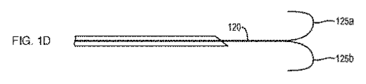
図1Bを参照すると、一実施形態において、第1スプラインおよび第2スプライン125a,125bは、第2形態にあるときに「T字形」を形成するように、長尺状部材120の長手軸線に略直交して移行または偏向している。図1Cを参照すると、一実施形態において、第1スプラインおよび第2スプライン125a,125bは、第2形態にあるときに「Y字形」を形成するように、長尺状部材120の長手軸線に略正接して移行または偏向している。図1Dを参照すると、一実施形態において、第1スプラインおよび第2スプライン125a,125bは、第2形態にあるときに「W字形」を形成するように、長尺状部材120の長手軸線に沿って/長手軸線上において長手軸線に対して平行に後方に屈曲している。図1Eを参照すると、一実施形態において、第1スプラインおよび第2スプライン125a,125bは、第2形態にあるときに対向した略丸状(例えば円形)の形状を形成するように、長尺状部材120の長手軸線に沿って/長手軸線上において後方に巻いている(curl back)。図1Fを参照すると、一実施形態において、第1スプラインおよび第2スプライン125a,125bは、第2形態にあるときに対向した略長円(oblong)(例えば楕円(elliptical)、細長い球形(elongate sphere)など)の形状を形成するように、長尺状部材120の長手軸線に沿って/長手軸線上において後方に巻いている。図1Gを参照すると、一実施形態において、第1スプラインおよび第2スプライン125a,125bは、第2形態にあるときに、長尺状部材の長手軸線から離間された(例えば、分離された)対向した略長円の形状を形成するように、長尺状部材の長手軸線に沿って/長手軸線上において後方に巻いている。長尺状部材120の遠位部分125は略対称構造を形成するように示されているが、様々な実施形態において、第1スプラインおよび第2スプライン125a,125bは、図1B〜図1Gに示した第2形態または示されていない他の形態の任意の組み合わせを形成してもよい。様々な実施形態において、第2形態にあるときに第1スプラインおよび第2スプライン125a,125bは、以下で検討するように、組織壁の内表面と接触して配置されるときに互いに独立して動作(例えば、偏向、屈曲、捻転、圧縮など)してもよい。
Referring to FIG. 1B, in one embodiment, the first spline and the
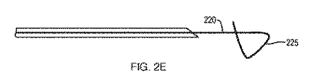
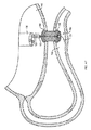
図2Aを参照すると、一実施形態において、本開示のシステム200は、近位端部(図示せず)、鋭利な遠位端部214、および近位端部と鋭利な遠位端部214との間に延びる管腔216を備えた組織穿通要素210(例えば針など)を含む。近位端部(図示せず)および遠位端部224を備えた長尺状部材220(例えばレール、ガイドワイヤなど)は、組織穿通要素210の管腔216内に摺動可能に配置されている。長尺状部材220の少なくとも遠位部分225は、組織穿通要素210の管腔216内に配置されたときの第1形態と、組織穿通要素210の鋭利な遠位端部214を越えて遠位に配置されている(進められている)ときの第2形態との間を移行するように構成された、当業において公知の様々な形状記憶材料(例えば金属、合金、ポリマーなど)を含んでいる。図2Bを参照すると、一実施形態において、第2形態にあるときに、長尺状部材220の遠位部分225は「ループ」または「フープ」を形成している。図2Cを参照すると、一実施形態において、長尺状部材220の遠位部分225は、第2形態にあるときに、長尺状部材220の一部のまわりで「反転したコイル(reverse coil)」または「反転したらせん(reverse spiral)」を形成するように、長尺状部材220の長手軸線に対して約180度屈曲している。図2Dを参照すると、一実施形態において、長尺状部材220の遠位部分225は、第2形態にあるときに、「8の字」、「輪縄」、または「コルクスクリュー」形を形成している。図2Eを参照すると、一実施形態において、長尺状部材220の遠位部分225は、第2形態にあるときに、長尺状部材220の長手軸線を横切って延びる「クロスバー」を形成するように屈曲している。
Referring to FIG. 2A, in one embodiment, the
遠位部分125,225の様々な第2形態は、長尺状部材120,220を近位に後退させたときに遠位組織壁をさらに固定する/動かなくするために、多くの付加的な利点を提供する。限定されない例として、図1B〜図1Dのいずれかに示した第1突起および第2突起125a,125bの端部は、遠位組織壁内に部分的に穿通され/埋め込まれる。図1B〜図1Gのいずれかのスプライン125a,125bの一部、または図2B〜図2Eの長尺状部材220の遠位部分225の一部は、遠位組織の内壁に対する摩擦を増強するために、1つ以上のフック、逆刺、突起などを備えていてもよい。様々な実施形態において、長尺状部材220のスプライン125a,125bおよび/または遠位部分225は、長尺状部材120,220を近位に後退させるときに保定圧力(retention pressure)を漸増させ、それにより医療専門家が医療手技を通じて必要に応じて遠位組織壁の内表面に及ぼす固定力(immobilizing force)を増減することを可能にする。加えて、またはこれ代わって、図1B〜図1Dのいずれかのスプライン125a,125bの表面の一部は、第1組織壁内および/または第2組織壁内において組織穿通要素110の鋭利な遠位端部114によって作成された穿刺孔を拡大または拡張するように構成された鋭利な刃を備えていてもよい。図1E〜図1Gの球状形または長円形の一方または双方はそれぞれ、遠位組織のより大きな表面積にわたって保定圧力を与えるために、長尺状部材120の長手軸線から離れて偏向(例えば、屈曲、拡開など)していてもよい。
Various second forms of the distal portions 125,225 have many additional forms to further secure / immobilize the distal tissue wall when the
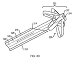
図3A〜図3Cを参照すると、一実施形態において、本開示のシステム300は、近位端部(図示せず)、鋭利な遠位端部314、および近位端部と鋭利な遠位端部314との間に延びる管腔316を備えた組織穿通要素310(例えば針など)を備える。長尺状部材320は、組織穿通要素310の管腔316内に摺動可能に配置されている。長尺状部材320は、シース326内に摺動可能に配置されたコントロールロッド322を備える。コントロールロッド322の遠位端部324は、シース326の遠位端部327に取り付けられている。シース326の遠位部分325は内部に形成された1つ以上のスリット329を備えており、組織穿通要素310の管腔316内に配置されたときの第1形態(図3A)と、組織穿通要素310の鋭利な遠位端部314を越えて遠位に配置されたときの第2形態(図3C)との間を移行するように構成されている。
Referring to FIGS. 3A-3C, in one embodiment, the
例えば、シース326の少なくとも遠位部分325は、例えばレーザー切断を用いて1つ以上のスリット329が形成された、例えばニチノール、ポリエーテルエーテルケトン(PEEK)などの形状記憶材料を含むが、それらに限定されない様々な材料を含んでいる。長尺状部材320は、コントロールロッド322を遠位に進めることにより、組織穿通要素320の管腔316を通って進められる(図3B)。一実施形態において、シース326の遠位部分325は、シース326をコントロールロッド322上において/コントロールロッド322に沿って遠位に進めることにより、第2形態に移行する。これに代わって、シース326の遠位部分325は、シース326を通して/シース326内においてコントロールロッド322を近位に後退させることにより、第2形態に移行してもよい(図3C)。いずれの実施形態においても、1つ以上のスリット329は、遠位部分325が遠位組織壁に係合するように構成された一連のアームまたは花弁部を備えた「バスケット」を形成することを可能にする。一実施形態において、遠位部分325は、遠位組織壁に対する摩擦を増強するために1つ以上のフック、逆刺、突起などを備えていてもよい。図3A〜図3Cは、遠位部分325が第2形態にあるときに5本のアームまたは花弁部を形成するように構成された5本のスリットを備えた実施形態を示しているが、様々な実施形態において、遠位部分は、様々な第2形態を形成するように構成されたいかなる数のスリットを備えていてもよい。
For example, at least the
一実施形態において、本願で開示した長尺状部材120,220,320は、当業において公知の細針吸引(fine−needle aspiration:FNA)または細針生検(fine−needle biopsy:FNB)手技に用いられる19ゲージ針または21ゲージ針を含む組織穿通要素110,210,310内に配置され、かつそれらの組織穿通要素110,210,310を通って送達される。加えて、またはこれに代わって、組織穿通要素110,210,310および/または長尺状部材120,220,320は、電気絶縁性および/または向上した潤滑性を与えるために、フッ素化ポリマーまたはパラレン(paralene)のようなコーティングを有利に備えていてもよい。近位組織壁または遠位組織壁のコアリング(coring)を防止するために、長尺状部材120,220,320の遠位部分125,225,325は、組織穿通要素110,210,310の鋭利な遠位端部114,214,314において、またはそれらの付近において、管腔116,216,316を閉塞するように構成されていてもよい。
In one embodiment, the
一実施形態において、本開示のシステム100,200,300は内視鏡のワーキングチャネルを通って送達される。図4Aを参照すると、使用時に、例として超音波内視鏡130は食道を通って第1体管腔140(例えば胃)内に進められる。内視鏡130の遠位端部132は、カメラ137、光源138および超音波振動子139を備えている。直視式(例えば光源138およびカメラ137)を用いて、内視鏡130の遠位端部132が第2体管腔150(例えば十二指腸または空腸)の組織壁152(例えば遠位組織壁)の近傍に位置する第1体管腔140の組織壁142(例えば近位組織壁)に隣接して配置される。次に、内視鏡130を直視式から超音波視に切り替える(例えば、光源138を消灯して、超音波振動子139を作動させる)ことにより、第2体管腔150が第1組織壁142を介して撮像される。システム100は次に、組織穿通要素110の鋭利な遠位端部114が第1組織壁および第2組織壁142,152に穿通して第2体管腔150内に延びるように、内視鏡130のワーキングチャネル136を通して進められる。
In one embodiment, the
図4Bを参照すると、長尺状部材120は、遠位部分125が第2体管腔150内において第2形態に移行するように、組織穿通要素の鋭利な遠位端部を越えて遠位に進められる。次に、組織穿通要素は、内視鏡130のワーキングチャネル136を通って長尺状部材120に沿って/長尺状部材120上において除去される(例えば近位に抜去される)。次に、長尺状部材120は、遠位部分125を第2遠位組織壁152の内側部分と接触させて配置するために、近位組織壁142に対する遠位組織壁152の移動を最小限にする、または防止する(例えば係留する)のに十分な力で、近位に後退させられる。
Referring to FIG. 4B, the
図4Cを参照すると、近位組織壁142および遠位組織壁152が互いに対して動かなない状態で、ステント162を装着したステントデリバリーシステム160が内視鏡130のワーキングチャネル136を通って進められる。ステントデリバリーシステム160は、長尺状部材120上において/長尺状部材120に沿って摺動するように構成された管腔166を備えている。ステントデリバリーシステム160の遠位端部は、第1組織壁および第2組織壁142,152を通る対向した開口(例えば孔)を作成するように構成された切除要素、例えば電気焼灼面、を備えている。一実施形態において、長尺状部材120の遠位部分125は、対向した開口を形成するときにステントデリバリーシステム160の電気焼灼面が圧迫する堅固な/頑丈な台を提供する。遠位部分125は、切除要素による意図しない切除を防止するために、第2体管腔150の反対側の組織壁とステントデリバリーシステムとの間の分離を確立するという付加的な利点を提供する。一実施形態において、遠位部分125の長円部分のうちの一方(または双方)は、遠位組織壁のより大きな表面積にわたって保定圧力を与えるために、長尺状部材120の長手軸線から離れて偏向していてもよい。加えて、またはこれに代わって、遠位部分125が長尺状部材120の長手軸線から離れて偏向する能力により、第2体管腔150の反対側の組織壁上に過剰な力を与えることなく、1)送達システム160の切除要素の第2体管腔150への完全な穿通、2)ステント162(図4D)の遠位フランジ166の妨げられない留置、および/または3)組織開口をさらに広げる(例えば拡大する)ための付加的な切除要素の導入を可能にする空間が提供される。加えて、長円形状は遠位部分125にある程度の可撓性を与えて、ステントデリバリーシステム160が、遠位部分125を反対側の組織壁にさらに押し付けることなく、遠位フランジを留置するために十分な距離だけ第2体管腔150内に進められるようにする。長尺状部材120の遠位部分125は、遠位部分125と反対側の組織壁との間に接触が生じた場合に反対側の組織壁への外傷を防止するために、軟質および/またはコンプライアントな表面またはコーティングを備えていてもよい。
Referring to FIG. 4C, the
図4Dを参照すると、次に、ステントデリバリーシステム160の外側部分が、ステント162の遠位フランジ166を第2体管腔150内に留置するために、内部管腔166、長尺状部材120およびステント162の上において近位に後退させられる。図4Eを参照すると、ステントデリバリーシステム160の外側部分は次いで、ステント162の近位フランジ164を第1体管腔140内に留置するために、内部管腔166、長尺状部材120およびステント162の上を通ってさらに後退させられる。図4Fを参照すると、近位フランジ164および遠位フランジ166が第1体管腔内140および第2体管腔150内において正確に留置された状態で、長尺状部材120は、管腔166を介してステントデリバリーシステムを除去するために遠位部分125が第2形態から第1形態に移行するような十分な力で、近位へ後退させられる。次に、内視鏡130、ステントデリバリーシステム160および長尺状部材120は患者から除去される。図4D〜図4Fに示したステント形態は、限定されない例として提供され、隣接した組織壁間に流れ経路を提供するために必要とされるような様々な異なる形状、形態、向き、寸法および/または材料を含んでいてもよい。加えて、ステントの外表面および/または内表面は、組織壁間における流体の漏出を防止するために、(例えば近位フランジと遠位フランジとの間の鞍状領域にわたって)完全にまたは部分的に被覆されていてもよい。図4E〜図4Fは、ステントの配置後において第1体管腔140と第2体管腔150との間に間隙を示しているが、他の実施形態では、上記手技により組織壁が鞍状領域に沿って互いに接触して並置されてもよく、近位フランジおよび遠位フランジは各組織壁のそれぞれの内表面との接触を提供する。
Referring to FIG. 4D, the outer portion of the
本願に開示したシステム100,200,300は、医療手技中に、いずれかの組織壁を他方の組織壁に向かって移動させるのではなく、近位組織壁と遠位組織壁とが互いから離れてしまうことを最小限にする、または防止するように構成されているが、一実施形態では、遠位フランジを第2体管腔150内に留置するために、遠位部分125,225,325が遠位組織壁をステントデリバリーシステム160上に引き上げるような十分な力で長尺状部材120,220,320を近位に後退させてもよい。
In the
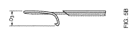
図5A〜図5Cを参照すると、一実施形態において、図2Eの長尺状部材220の遠位部分225は、長尺状部材220の長手軸線に対して第1寸法D1(例えば幅)、第2寸法D2(例えば高さ)および第3寸法D3(例えば高度)を有している。限定されない例として、第1寸法D1は約2.54cm(1.00インチ)であり、第2寸法D2は約1.98cm(0.78インチ)であり、第3寸法D3は約0.84cm(0.33インチ)である。様々な実施形態において、遠位部分225の第1寸法、第2寸法、および第3寸法D1〜D3は、長尺状部材の遠位部分225がステント留置手技中に第2体管腔の組織壁との接触を維持している間に、(例えば、上記で概説したように第2体管腔内において)ステント162の遠位フランジ165が留置される空間を提供する。
Referring to FIG. 5A~ Figure 5C, in one embodiment, the
様々な実施形態において、本願で開示した長尺状部材120,220,320は、破壊/破断することなく、また(例えば必要な保持強度を提供するために)第2体管腔内において第2形態に移行する能力を維持したまま、組織穿通要素または他の医療装置(例えば牽引カテーテルなど)に対して繰り返し摺動して出入りするために十分な可撓性および強度を備えている。加えて、本願に開示した長尺状部材120,220,320のいずれも、組織穿通要素または他の医療装置内における摺動運動を容易にするために適当なコーティングを含んでいてもよい。様々な実施形態において、そのようなコーティングはまた、長尺状部材の全体または一部に絶縁耐力を与えることもできる。
In various embodiments, the
本開示の医療装置は、内視鏡に限定されるものではなく、例えば、カテーテル、気管支鏡、尿管鏡、十二指腸内視鏡、結腸内視鏡、関節鏡、膀胱鏡、子宮鏡などを含む身体通路にアクセスするための様々な医療装置を含む。最後に、本開示の実施形態を内視鏡との使用について説明してきたが、本開示のシステムは、随伴する医療装置の不在下で患者内に配置されてもよい。 The medical apparatus of the present disclosure is not limited to an endoscope, and includes, for example, a catheter, a bronchoscope, a ureteroscope, a duodenal endoscope, a colon endoscope, an arthroscope, a cystoscope, a hysteroscope, and the like. Includes various medical devices for access to body passages. Finally, although embodiments of the present disclosure have been described for use with endoscopes, the systems of the present disclosure may be deployed within the patient in the absence of accompanying medical equipment.
本願において開示し権利請求する装置および/または方法はすべて、本開示を踏まえて、過度の実験作業を行うことなく、製造および実施することができる。この開示の装置および方法は好ましい実施形態に関して説明されているが、本開示の概念、趣旨および範囲から逸脱することなく、本願に記載した装置および/または方法に対して、並びにそれらの方法のステップまたはステップの順序において、変形例を適用できることは当業者には明らかである。当業者には明らかなそのような類似した代替物および変更例はすべて、添付する特許請求の範囲によって定義される本開示の趣旨、範囲および概念の内にあると考えられる。 All of the devices and / or methods disclosed and claimed in the present application can be manufactured and implemented in light of this disclosure without undue experimental work. Although the devices and methods of this disclosure have been described for preferred embodiments, without departing from the concepts, intent and scope of the present disclosure, with respect to the devices and / or methods described herein, and steps of those methods. Alternatively, it will be apparent to those skilled in the art that variations can be applied in the order of the steps. All such similar alternatives and modifications apparent to those skilled in the art are believed to be within the spirit, scope and concept of the present disclosure as defined by the appended claims.
Claims (15)
近位端部、
鋭利な遠位端部、および
前記近位端部と遠位端部との間に延びる管腔
を備えた、針と、
前記管腔内に摺動可能に配置されるとともに、近位端部および遠位端部を有する長尺状部材と、を備え、
前記長尺状部材の遠位部分は、前記管腔内に配置されたときの第1形態と、前記鋭利な遠位端部を越えて遠位に配置されたときの第2形態との間を移行するように構成されており、
前記長尺状部材の遠位部分は、第2形態にあり、かつ、遠位の体管腔の組織壁に接触しているときに、該長尺状部材の近位端部が近位に移動するにつれて、近位の体管腔の組織壁に対する遠位の体管腔の組織壁の移動を最小限にするように構成されている、システム。 It ’s a needle,
Proximal end,
A needle with a sharp distal end and a lumen extending between the proximal and distal ends.
Rutotomoni slidably disposed within the lumen, and a elongate member having a proximal end and a distal end,
The distal portion of the elongated member is between the first form when placed in the lumen and the second form when placed distally beyond the sharp distal end. is configured to migrate,
The distal portion of the elongated member is in the second form and the proximal end of the elongated member is proximal when in contact with the tissue wall of the distal body lumen. A system that is configured to minimize the movement of the tissue wall of the distal body lumen with respect to the tissue wall of the proximal body lumen as it moves.
コントロールロッドと、
前記コントロールロッドのまわりに摺動可能に配置されたシースと、を備え、
前記シースの遠位部分は内部に形成された少なくとも1つの長手方向スリットを備えており、
前記コントロールロッドの遠位端部は前記シースの遠位端部に取り付けられている、請求項1に記載のシステム。 The long member is
With the control rod
A sheath, which is slidably arranged around the control rod, is provided.
The distal portion of the sheath comprises at least one longitudinal slit formed internally.
The system of claim 1, wherein the distal end of the control rod is attached to the distal end of the sheath.
Applications Claiming Priority (3)
| Application Number | Priority Date | Filing Date | Title |
|---|---|---|---|
| US201762476995P | 2017-03-27 | 2017-03-27 | |
| US62/476,995 | 2017-03-27 | ||
| PCT/US2018/024341 WO2018183191A1 (en) | 2017-03-27 | 2018-03-26 | Systems to effect movement of tissue structures |
Publications (2)
| Publication Number | Publication Date |
|---|---|
| JP2020503984A JP2020503984A (en) | 2020-02-06 |
| JP6845337B2 true JP6845337B2 (en) | 2021-03-17 |
Family
ID=62002402
Family Applications (1)
| Application Number | Title | Priority Date | Filing Date |
|---|---|---|---|
| JP2019539925A Active JP6845337B2 (en) | 2017-03-27 | 2018-03-26 | System for moving organizational structure |
Country Status (5)
| Country | Link |
|---|---|
| US (2) | US10912566B2 (en) |
| EP (1) | EP3551086A1 (en) |
| JP (1) | JP6845337B2 (en) |
| CN (2) | CN116369997A (en) |
| WO (1) | WO2018183191A1 (en) |
Families Citing this family (7)
| Publication number | Priority date | Publication date | Assignee | Title |
|---|---|---|---|---|
| WO2019046352A1 (en) * | 2017-08-30 | 2019-03-07 | Sanford Health | Anchoring guide wire and methods for use thereof |
| CN114728131A (en) | 2019-12-06 | 2022-07-08 | 波士顿科学国际有限公司 | Endoscope ultrasound guided puncture needle |
| CN115023203A (en) | 2020-01-31 | 2022-09-06 | 波士顿科学国际有限公司 | Atraumatic delivery system |
| JP2023543775A (en) * | 2020-09-25 | 2023-10-18 | ボストン サイエンティフィック サイムド,インコーポレイテッド | adjustable luminal apposition stent |
| US20220096198A1 (en) | 2020-09-28 | 2022-03-31 | Boston Scientific Scimed, Inc. | Devices, systems, and methods for locating a body lumen |
| CA3217876A1 (en) | 2021-05-19 | 2022-11-24 | Boston Scientific Scimed, Inc. | Devices, systems, and methods for adjusting a passage through an implantable device |
| US20230233349A1 (en) * | 2022-01-21 | 2023-07-27 | Covidien Lp | Apparatuses for stent delivery and positioning for transluminal application |
Family Cites Families (21)
| Publication number | Priority date | Publication date | Assignee | Title |
|---|---|---|---|---|
| US6092526A (en) * | 1997-06-19 | 2000-07-25 | Scimed Life Systems, Inc. | Percutaneous chamber-to-artery bypass |
| US20040122456A1 (en) | 2002-12-11 | 2004-06-24 | Saadat Vahid C. | Methods and apparatus for gastric reduction |
| US20040073237A1 (en) * | 2002-10-08 | 2004-04-15 | Leinsing Karl R. | Surgical fastener and delivery system |
| US8328710B2 (en) * | 2002-11-06 | 2012-12-11 | Senorx, Inc. | Temporary catheter for biopsy site tissue fixation |
| JP4731471B2 (en) * | 2003-04-16 | 2011-07-27 | ジェネシス・テクノロジーズ・エルエルシー | Medical devices and methods |
| US7361180B2 (en) * | 2004-05-07 | 2008-04-22 | Usgi Medical, Inc. | Apparatus for manipulating and securing tissue |
| US7988690B2 (en) | 2004-01-30 | 2011-08-02 | W.L. Gore & Associates, Inc. | Welding systems useful for closure of cardiac openings |
| WO2006017754A1 (en) * | 2004-08-05 | 2006-02-16 | Vnus Medical Technologies, Inc. | Methods and apparatus for coagulating and/or constricting hollow anatomical structures |
| US8926633B2 (en) * | 2005-06-24 | 2015-01-06 | Abbott Laboratories | Apparatus and method for delivering a closure element |
| US7850686B2 (en) * | 2006-03-30 | 2010-12-14 | Ethicon Endo-Surgery, Inc. | Protective needle knife |
| US9226772B2 (en) * | 2009-01-30 | 2016-01-05 | Ethicon Endo-Surgery, Inc. | Surgical device |
| US20100268029A1 (en) * | 2009-04-21 | 2010-10-21 | Xlumena, Inc. | Methods and apparatus for advancing a device from one body lumen to another |
| US20110137394A1 (en) * | 2009-05-29 | 2011-06-09 | Xlumena, Inc. | Methods and systems for penetrating adjacent tissue layers |
| JP5535313B2 (en) * | 2009-05-29 | 2014-07-02 | エックスルミナ, インコーポレイテッド | Device and method for deploying a stent across adjacent tissue layers |
| EP2760328B1 (en) * | 2011-09-30 | 2023-02-22 | Bioventrix, Inc. | Remote pericardial hemostasis for ventricular access and reconstruction or other organ therapies |
| US9883855B2 (en) | 2012-01-25 | 2018-02-06 | St. Jude Medical, Llc | Apparatus and method for heart valve repair |
| US20130211415A1 (en) * | 2012-02-09 | 2013-08-15 | Boston Scientific Scimed, Inc. | Steerable tissue manipulation medical devices and related methods of use |
| US9033917B2 (en) * | 2012-08-15 | 2015-05-19 | Abbott Cardiovascular Systems Inc. | Needle catheter for delivery of agents directly into vessel wall |
| US10376674B2 (en) * | 2014-09-15 | 2019-08-13 | Ethicon, Inc. | System and method for targeted delivery of therapeutic agents to tissue |
| US10603018B2 (en) * | 2014-12-16 | 2020-03-31 | Intervene, Inc. | Intravascular devices, systems, and methods for the controlled dissection of body lumens |
| US10111715B2 (en) * | 2015-05-11 | 2018-10-30 | Veran Medical Technologies, Inc. | Adjustable length medical instrument assembly with localization elements for tracking medical instrument extension |
-
2018
- 2018-03-26 CN CN202310012958.1A patent/CN116369997A/en active Pending
- 2018-03-26 WO PCT/US2018/024341 patent/WO2018183191A1/en unknown
- 2018-03-26 EP EP18718271.2A patent/EP3551086A1/en active Pending
- 2018-03-26 CN CN201880021646.4A patent/CN110461249B/en active Active
- 2018-03-26 US US15/935,969 patent/US10912566B2/en active Active
- 2018-03-26 JP JP2019539925A patent/JP6845337B2/en active Active
-
2021
- 2021-01-06 US US17/142,659 patent/US20210145442A1/en active Pending
Also Published As
| Publication number | Publication date |
|---|---|
| CN110461249B (en) | 2023-01-31 |
| US10912566B2 (en) | 2021-02-09 |
| US20210145442A1 (en) | 2021-05-20 |
| CN110461249A (en) | 2019-11-15 |
| JP2020503984A (en) | 2020-02-06 |
| CN116369997A (en) | 2023-07-04 |
| US20180271530A1 (en) | 2018-09-27 |
| WO2018183191A1 (en) | 2018-10-04 |
| EP3551086A1 (en) | 2019-10-16 |
Similar Documents
| Publication | Publication Date | Title |
|---|---|---|
| JP6845337B2 (en) | System for moving organizational structure | |
| US20140357946A1 (en) | Tissue spreader for accessing papilla, and related methods of use | |
| JP4611301B2 (en) | System and method for introducing multiple medical devices | |
| US8328841B2 (en) | Embolization coil delivery systems and methods | |
| JP5867746B2 (en) | 3D retractor | |
| EP1852083B1 (en) | Tri-bending sphinctertome | |
| US20090005637A1 (en) | Method and Apparatus for Measuring and Controlling Blade Depth of a Tissue Cutting Apparatus in an Endoscopic Catheter | |
| US9872600B2 (en) | Tissue resection bander and related methods of use | |
| US20060015006A1 (en) | System and method for accessing a body cavity | |
| US9770252B2 (en) | Retrieval device and related methods of use | |
| JP2016512458A (en) | Ablation device and related methods of use | |
| JP5912473B2 (en) | Micro Snake Retractor | |
| JP5224298B2 (en) | Lumen wall puncture overtube | |
| JP6211234B2 (en) | Endoscope attachment and endoscope system | |
| US8857441B2 (en) | Biological tissue transfer method and biological tissue treatment method | |
| US20220117618A1 (en) | Tissue deflecting devices and related methods of use | |
| US20220192670A1 (en) | Devices, systems, and methods for anchoring tissue | |
| Chapter | Endoscopes, and Accessories Guidewires | |
| JP2019505268A (en) | Medical device and method of use |
Legal Events
| Date | Code | Title | Description |
|---|---|---|---|
| A621 | Written request for application examination |
Free format text: JAPANESE INTERMEDIATE CODE: A621 Effective date: 20190723 |
|
| A977 | Report on retrieval |
Free format text: JAPANESE INTERMEDIATE CODE: A971007 Effective date: 20200720 |
|
| A131 | Notification of reasons for refusal |
Free format text: JAPANESE INTERMEDIATE CODE: A131 Effective date: 20200804 |
|
| A521 | Request for written amendment filed |
Free format text: JAPANESE INTERMEDIATE CODE: A523 Effective date: 20201023 |
|
| TRDD | Decision of grant or rejection written | ||
| A01 | Written decision to grant a patent or to grant a registration (utility model) |
Free format text: JAPANESE INTERMEDIATE CODE: A01 Effective date: 20210202 |
|
| A61 | First payment of annual fees (during grant procedure) |
Free format text: JAPANESE INTERMEDIATE CODE: A61 Effective date: 20210225 |
|
| R150 | Certificate of patent or registration of utility model |
Ref document number: 6845337 Country of ref document: JP Free format text: JAPANESE INTERMEDIATE CODE: R150 |
|
| R250 | Receipt of annual fees |
Free format text: JAPANESE INTERMEDIATE CODE: R250 |