JP6843268B2 - A timekeeper with a mechanical movement whose movement is enhanced by an adjustment device - Google Patents
A timekeeper with a mechanical movement whose movement is enhanced by an adjustment device Download PDFInfo
- Publication number
- JP6843268B2 JP6843268B2 JP2019553304A JP2019553304A JP6843268B2 JP 6843268 B2 JP6843268 B2 JP 6843268B2 JP 2019553304 A JP2019553304 A JP 2019553304A JP 2019553304 A JP2019553304 A JP 2019553304A JP 6843268 B2 JP6843268 B2 JP 6843268B2
- Authority
- JP
- Japan
- Prior art keywords
- mechanical
- braking
- pulse
- oscillator
- frequency
- Prior art date
- Legal status (The legal status is an assumption and is not a legal conclusion. Google has not performed a legal analysis and makes no representation as to the accuracy of the status listed.)
- Active
Links
- 230000000737 periodic effect Effects 0.000 claims description 53
- 230000007935 neutral effect Effects 0.000 claims description 35
- 230000001360 synchronised effect Effects 0.000 claims description 30
- 230000007246 mechanism Effects 0.000 claims description 19
- 230000005291 magnetic effect Effects 0.000 claims description 12
- 238000012423 maintenance Methods 0.000 claims description 4
- 238000005381 potential energy Methods 0.000 claims description 3
- 230000004913 activation Effects 0.000 claims description 2
- 238000012937 correction Methods 0.000 description 21
- 230000000694 effects Effects 0.000 description 15
- 230000004048 modification Effects 0.000 description 15
- 238000012986 modification Methods 0.000 description 15
- 230000008878 coupling Effects 0.000 description 13
- 238000010168 coupling process Methods 0.000 description 13
- 238000005859 coupling reaction Methods 0.000 description 13
- 230000007423 decrease Effects 0.000 description 12
- 238000010586 diagram Methods 0.000 description 10
- 230000003993 interaction Effects 0.000 description 10
- 238000013459 approach Methods 0.000 description 9
- 230000010363 phase shift Effects 0.000 description 9
- 101100126074 Caenorhabditis elegans imp-2 gene Proteins 0.000 description 6
- 101100452131 Rattus norvegicus Igf2bp1 gene Proteins 0.000 description 6
- 230000006870 function Effects 0.000 description 6
- 238000000034 method Methods 0.000 description 6
- 239000013078 crystal Substances 0.000 description 4
- 230000001965 increasing effect Effects 0.000 description 4
- 230000010355 oscillation Effects 0.000 description 4
- 102100036341 Importin-4 Human genes 0.000 description 3
- 230000008901 benefit Effects 0.000 description 3
- 230000004907 flux Effects 0.000 description 3
- 230000008569 process Effects 0.000 description 3
- 230000007704 transition Effects 0.000 description 3
- 101100171060 Caenorhabditis elegans div-1 gene Proteins 0.000 description 2
- 101710125768 Importin-4 Proteins 0.000 description 2
- 101000852542 Mus musculus Importin-4 Proteins 0.000 description 2
- 230000001133 acceleration Effects 0.000 description 2
- 238000013016 damping Methods 0.000 description 2
- 238000013461 design Methods 0.000 description 2
- 239000000203 mixture Substances 0.000 description 2
- 230000004044 response Effects 0.000 description 2
- 238000012216 screening Methods 0.000 description 2
- 230000035939 shock Effects 0.000 description 2
- 230000001960 triggered effect Effects 0.000 description 2
- 101000852543 Homo sapiens Importin-4 Proteins 0.000 description 1
- 101150018873 IMP1 gene Proteins 0.000 description 1
- 102100036340 Importin-5 Human genes 0.000 description 1
- 101710125769 Importin-5 Proteins 0.000 description 1
- 230000009471 action Effects 0.000 description 1
- 210000003423 ankle Anatomy 0.000 description 1
- 230000008859 change Effects 0.000 description 1
- 230000003750 conditioning effect Effects 0.000 description 1
- 230000001186 cumulative effect Effects 0.000 description 1
- 238000001514 detection method Methods 0.000 description 1
- 230000001627 detrimental effect Effects 0.000 description 1
- 238000011161 development Methods 0.000 description 1
- 239000003302 ferromagnetic material Substances 0.000 description 1
- 238000009472 formulation Methods 0.000 description 1
- 230000001939 inductive effect Effects 0.000 description 1
- 238000002955 isolation Methods 0.000 description 1
- 239000000696 magnetic material Substances 0.000 description 1
- 230000014759 maintenance of location Effects 0.000 description 1
- 230000003071 parasitic effect Effects 0.000 description 1
- 239000010453 quartz Substances 0.000 description 1
- 230000009467 reduction Effects 0.000 description 1
- 230000000630 rising effect Effects 0.000 description 1
- VYPSYNLAJGMNEJ-UHFFFAOYSA-N silicon dioxide Inorganic materials O=[Si]=O VYPSYNLAJGMNEJ-UHFFFAOYSA-N 0.000 description 1
- 230000006641 stabilisation Effects 0.000 description 1
- 238000011105 stabilization Methods 0.000 description 1
- 230000002459 sustained effect Effects 0.000 description 1
Images


Classifications
-
- G—PHYSICS
- G04—HOROLOGY
- G04C—ELECTROMECHANICAL CLOCKS OR WATCHES
- G04C3/00—Electromechanical clocks or watches independent of other time-pieces and in which the movement is maintained by electric means
- G04C3/04—Electromechanical clocks or watches independent of other time-pieces and in which the movement is maintained by electric means wherein movement is regulated by a balance
- G04C3/042—Electromechanical clocks or watches independent of other time-pieces and in which the movement is maintained by electric means wherein movement is regulated by a balance using mechanical coupling
- G04C3/045—Electromechanical clocks or watches independent of other time-pieces and in which the movement is maintained by electric means wherein movement is regulated by a balance using mechanical coupling with constant impulses
-
- G—PHYSICS
- G04—HOROLOGY
- G04C—ELECTROMECHANICAL CLOCKS OR WATCHES
- G04C13/00—Driving mechanisms for clocks by master-clocks
- G04C13/02—Circuit arrangements; Electric clock installations
- G04C13/028—Circuit arrangements; Electric clock installations transmission systems for synchronisation of pendulum of slave-clocks by pendulums of master-clocks
-
- H—ELECTRICITY
- H03—ELECTRONIC CIRCUITRY
- H03B—GENERATION OF OSCILLATIONS, DIRECTLY OR BY FREQUENCY-CHANGING, BY CIRCUITS EMPLOYING ACTIVE ELEMENTS WHICH OPERATE IN A NON-SWITCHING MANNER; GENERATION OF NOISE BY SUCH CIRCUITS
- H03B5/00—Generation of oscillations using amplifier with regenerative feedback from output to input
- H03B5/30—Generation of oscillations using amplifier with regenerative feedback from output to input with frequency-determining element being electromechanical resonator
- H03B5/32—Generation of oscillations using amplifier with regenerative feedback from output to input with frequency-determining element being electromechanical resonator being a piezoelectric resonator
-
- H—ELECTRICITY
- H03—ELECTRONIC CIRCUITRY
- H03B—GENERATION OF OSCILLATIONS, DIRECTLY OR BY FREQUENCY-CHANGING, BY CIRCUITS EMPLOYING ACTIVE ELEMENTS WHICH OPERATE IN A NON-SWITCHING MANNER; GENERATION OF NOISE BY SUCH CIRCUITS
- H03B5/00—Generation of oscillations using amplifier with regenerative feedback from output to input
- H03B5/30—Generation of oscillations using amplifier with regenerative feedback from output to input with frequency-determining element being electromechanical resonator
- H03B5/40—Generation of oscillations using amplifier with regenerative feedback from output to input with frequency-determining element being electromechanical resonator being a magnetostrictive resonator
Description
本発明は、機械式ムーブメントを備えた計時器に関し、機械式ムーブメントの動作をペーシングする機械式振動子の動作における潜在的な時間ドリフトを修正するためのデバイスによって動作が強化される。このような時間ドリフトは、特に機械式振動子の平均固有振動周期が設定点周期に等しくない場合に発生する。この設定点周期は、修正デバイスに関連付けられている補助振動子によって決定される。 The present invention relates to a timekeeper with a mechanical movement, the operation of which is enhanced by a device for correcting potential time drift in the operation of the mechanical oscillator pacing the operation of the mechanical movement. Such time drift occurs especially when the average natural vibration period of the mechanical oscillator is not equal to the set point period. This set point period is determined by the auxiliary oscillator associated with the modification device.
特に、計時器は、一方では、
− 少なくとも1つの時間データアイテムの表示機構と、
− その最小位置エネルギ状態に対応するニュートラル位置を中心に、一般的な振動軸に沿って振動するのに適した機械式共振器と、
− 表示機構の動作をペーシングするように配置された機械式振動子とともに形を成す機械式共振器のメンテナンスデバイスであって、この機械式振動子の各振動は、振動周期を画定する、メンテナンスデバイスとを備えた機械式ムーブメントによって、
他方では、計時器の動作を高めるために、機械式振動子の中間周波数を調整するためのデバイスによって、形成される。
In particular, the timekeeper, on the one hand,
-At least one time data item display mechanism and
− A mechanical resonator suitable for vibrating along a general vibration axis centered on the neutral position corresponding to its minimum potential energy state.
− A maintenance device for a mechanical resonator that forms with a mechanical oscillator arranged to pace the operation of the display mechanism, where each vibration of this mechanical oscillator defines a vibration cycle. By a mechanical movement with and
On the other hand, it is formed by a device for adjusting the intermediate frequency of the mechanical oscillator in order to enhance the operation of the timekeeper.
本発明の分野で定義される計時器は、いくつかの先行文献で提案されている。1977年に公開されたスイス国特許発明第597636号は、図3を参照してこのような計時器を提案している。ムーブメントには、てん輪−ヒゲゼンマイと、従来のメンテナンスデバイスとによって形成された共振器が装備されており、従来のメンテナンスデバイスは、アセンブリと、ばねを備えたバレルに運動学的に連結されたガンギ車とが装備されている。この計時器ムーブメントはさらに、その機械式振動子の周波数を調整するためのデバイスを備えている。この調整デバイスは、電子回路と、てん輪のフェローの下に配置された支持体に配置されたフラットコイルから、および、てん輪に取り付けられ、振動子が起動されたときに、ともにコイルを通過するように互いに近接して配置された2つの磁石から形成された磁気アセンブリと、を備えている。 Timekeepers defined in the field of the present invention have been proposed in several prior documents. Swiss Patent Invention No. 579636, published in 1977, proposes such a timekeeper with reference to FIG. The movement is equipped with a resonator formed by a balance spring-spring and a conventional maintenance device, which is kinematically connected to an assembly and a barrel with a spring. It is equipped with an escape wheel. The timekeeper movement is further equipped with a device for adjusting the frequency of its mechanical oscillator. This tuning device passes through the coil both from the electronic circuit and from a flat coil placed on a support placed under the fellow of the balance wheel, and when attached to the balance wheel and the oscillator is activated. It comprises a magnetic assembly formed of two magnets arranged in close proximity to each other so as to.
電子回路は、水晶共振器を備えるとともに基準周波数信号FRを生成する働きをする時間基準を備え、この基準周波数は、機械式振動子の周波数FGと比較される。振動子の周波数FGは、一対の磁石によってコイルにおいて生成された電気信号を介して検出される。調整回路は、磁気磁石コイルの結合およびコイルに接続された切り替え可能な負荷を介して、瞬間的に制動トルクを誘導するのに適している。 The electronic circuit comprises a crystal resonator and a time reference that serves to generate a reference frequency signal FR, the reference frequency being compared with the frequency FG of the mechanical oscillator. The frequency FG of the oscillator is detected via an electrical signal generated in the coil by a pair of magnets. The tuning circuit is suitable for instantaneously inducing braking torque through the coupling of the magnetic magnet coil and the switchable load connected to the coil.
てん輪−ヒゲゼンマイを電子調整回路と結合するために、磁気コイル式電磁システムを使用することは、様々な問題を引き起こす。第1に、てん輪上の永久磁石の配置により、計時器ムーブメントに常に磁束が存在し、この磁束が空間的に周期的に変化する。このような磁束は、計時器ムーブメントの要素の様々な部位、特に強磁性材料で作られた部品のような磁性材料で作られた要素に有害な作用を及ぼす可能性がある。これは、計時器ムーブメントの適切な動作に影響を与え、旋回要素の摩耗を増加させる可能性がある。確かに、問題となっている磁気システムをある程度スクリーニングすることが想定され得るが、スクリーニングには、てん輪によって支えられる特定の要素が必要である。このようなスクリーニングは、機械式共振器のサイズおよびその重量を増加させる傾向がある。さらに、それはてん輪−ヒゲゼンマイの美的構成の可能性を制限する。 The use of a magnetic coiled electromagnetic system to couple the balance spring-spring with an electronic conditioning circuit causes various problems. First, due to the arrangement of the permanent magnets on the balance wheel, a magnetic flux is always present in the timekeeping movement, and this magnetic flux changes spatially and periodically. Such magnetic flux can have a detrimental effect on various parts of the elements of the timekeeping movement, especially those made of magnetic materials such as parts made of ferromagnetic materials. This affects the proper operation of the timekeeping movement and can increase the wear of the swivel element. Indeed, it can be envisioned to screen the magnetic system in question to some extent, but screening requires certain elements supported by the balance wheel. Such screening tends to increase the size and weight of the mechanical resonator. In addition, it limits the possibilities of the balance spring-spring aesthetic composition.
当業者は、電気機械式であるそのてん輪−ヒゲゼンマイの周波数を調整するためのデバイスが関連付けられた機械式計時器ムーブメントも認識している。より具体的には、調整は、てん輪−ヒゲゼンマイと、調整デバイスとの間の機械的な相互作用を介して発生し、調整デバイスは、てん輪に配置された停止部と、可動フィンガを装備したアクチュエータとで形成されたシステムによって、振動しているてん輪に作用するように配置され、可動フィンガは、停止部の方向において、制動周波数で作動されるが、てん輪のフェローに触れることはない。このような計時器は、文献仏国特許発明第2162404号に記載されている。この文献で提案された概念によれば、機械式振動子が設定点周波数に対して時間ドリフトを示す場合、フィンガと停止部との間の相互作用によって、機械式振動子の周波数を、水晶共振器の周波数に同期させることが求められ、フィンガは、てん輪を瞬間的にロックすることができる、てん輪はその後、特定の時間間隔の間、その動きを停止される(てん輪がそのニュートラル位置に向かって戻ったとき、停止部は、その方向に移動したフィンガを支える)、または、てん輪がその終了角度位置のうちの1つの方向に回転している間、フィンガが停止部に到達したとき、振動振幅を制限する(振幅を画定する)ことができると想定されており、フィンガは、その後、振動を停止し、てん輪は、反対方向に直進移動し始める。 Those skilled in the art are also aware of a mechanical timepiece movement associated with a device for adjusting the frequency of its balance spring-spring, which is electromechanical. More specifically, the adjustment occurs through a mechanical interaction between the balance wheel-beard and the adjustment device, which provides a stop located on the balance wheel and a movable finger. A system formed by the equipped actuators is arranged to act on the vibrating balance wheel, the movable finger is operated at the braking frequency in the direction of the stop, but touches the balance wheel fellow. There is no. Such a timekeeper is described in French Patent Invention No. 2162404. According to the concept proposed in this document, when the mechanical oscillator shows a time drift with respect to the set point frequency, the interaction between the finger and the stop causes the frequency of the mechanical oscillator to crystallize. Required to synchronize to the frequency of the vessel, the finger can momentarily lock the balance wheel, the balance wheel is then stopped in its movement for a certain time interval (the balance wheel is in its neutral position). When returning towards a position, the stop supports the finger that has moved in that direction), or the finger reaches the stop while the balance wheel is rotating in one of its end angular positions. At that time, it is assumed that the vibration amplitude can be limited (defining the amplitude), the finger then stops the vibration, and the balance wheel begins to move straight in the opposite direction.
このような調整システムは、多くの欠点を有し、動作システムを形成できることが真に疑われ得る。停止部の振動運動に対するフィンガの周期的な作動、およびこの停止部に向かうフィンガの周期的な運動に対する停止部の振動に対する潜在的に大きな初期位相シフトは、多くの問題を引き起こす。フィンガと停止部との間の相互作用は、てん輪の単一の角度位置に限定され、この角度位置は、てん輪−ヒゲゼンマイの軸に対するアクチュエータの角度位置と、アイドル時のてん輪における停止部の(そのニュートラル位置を画定する)角度位置とによって画定されることに留意されたい。実際、フィンガの運動は、停止部との接触によっててん輪を停止することを可能にすると想定されるが、フィンガは、てん輪のフェローと接触しないように配置される。さらに、フィンガと停止部との間の相互作用の時間は、てん輪−ヒゲゼンマイの振動の振幅にも依存することに留意されたい。 Such a coordinating system has many drawbacks and it can be truly suspected that it can form an operating system. The periodic actuation of the finger with respect to the vibrational motion of the stop and the potentially large initial phase shift with respect to the vibration of the stop with respect to the periodic motion of the finger towards this stop causes many problems. The interaction between the finger and the stop is limited to a single angular position on the balance wheel, which is the angular position of the actuator with respect to the balance spring-spring axis and the stop on the balance spring at idle. Note that it is defined by the angular position (which defines its neutral position) of the part. In fact, the movement of the fingers is supposed to allow the balance wheel to be stopped by contact with the stop, but the fingers are arranged so that they do not come into contact with the fellows of the balance wheel. Furthermore, it should be noted that the time of interaction between the finger and the stop also depends on the amplitude of the balance spring-spring vibration.
求められている同期はありそうもないことに留意されたい。確かに、特に、周波数は、フィンガの前後運動を計時する設定点周波数よりも大きく、フィンガと、その2つの終了角度位置のうちの一方から戻るてん輪を瞬間的に保持する停止部との間の第1の相互作用(誤差を低減する修正)を伴うてん輪−ヒゲゼンマイの場合、第2の相互作用は、フィンガの半周期運動中に、停止部がフィンガに触れずに、何度も振動した後、フィンガの振動方向を即座に反転させることによる、フィンガによるてん輪の停止となり、ここでは、停止部がフィンガに当接する一方、てん輪は、前記終了角度位置に向かって回転する(誤差を増加させる修正)。したがって、たとえば数百の振動周期などの長い時間間隔の間、未修正の時間ドリフトがあるだけではなく、フィンガと停止部との間のいくつかの相互作用により、時間ドリフトは、減少するのではなく、増加する。さらに、上記の第2の相互作用中の停止部の、ひいては、てん輪−ヒゲゼンマイの、振動の位相シフトは、フィンガと停止部(そのニュートラル位置にあるてん輪)との間の相対的な角度位置にしたがって大きくなる可能性があることに留意されたい。 Note that the required synchronization is unlikely. Indeed, in particular, the frequency is greater than the setpoint frequency at which the finger moves back and forth, between the finger and the stop that momentarily holds the balance wheel returning from one of its two end angle positions. In the case of a balance wheel-higezenmai with the first interaction (correction to reduce error), the second interaction occurs many times during the finger's half-cycle motion, without the stop touching the finger. After vibrating, the finger stops the balance wheel by immediately reversing the vibration direction of the finger. Here, the stop portion abuts on the finger, while the balance wheel rotates toward the end angle position (the end angle position). Corrections that increase the error). Therefore, not only is there uncorrected time drift over long time intervals, such as hundreds of vibration cycles, but some interaction between the finger and the stop may reduce the time drift. Not increase. In addition, the phase shift of the vibration of the stop during the second interaction, and thus the balance spring-spring, is relative between the finger and the stop (the balance wheel in its neutral position). Note that it can increase with angular position.
したがって、所望される同期が得られることは疑わしい。さらに、特に、てん輪−ヒゲゼンマイの固有周波数は、設定点周波数に近いが等しくない場合、この時点でフィンガの反対側に位置する停止部によって、てん輪に向かう動きにフィンガがロックされるシナリオは、予見可能である。このような寄生相互作用は、機械式振動子および/またはアクチュエータに損傷を与える可能性がある。さらに、これは実際に、フィンガの接線範囲を制限する。最後に、停止部との相互作用位置でのフィンガの保持期間は比較的短くなければならないため、遅延を誘発する修正が制限される。結論として、文献仏国特許発明第2162404号で提案されている計時器の動作は、当業者には非常にありそうにないように見え、当業者は、このような教示を思いとどまる。 Therefore, it is doubtful that the desired synchronization will be obtained. Furthermore, in particular, if the natural frequency of the balance spring is close to the set point frequency but not equal, the stop located on the opposite side of the finger at this point locks the finger in the movement toward the balance spring. Is foreseeable. Such parasitic interactions can damage mechanical oscillators and / or actuators. Moreover, this actually limits the tangential range of the fingers. Finally, the retention period of the finger at the interaction position with the stop must be relatively short, limiting the modifications that induce delay. In conclusion, the operation of the timekeeper proposed in the French Patent Invention No. 2162404 seems very unlikely to those skilled in the art, and those skilled in the art discourage such teachings.
本発明の目的は、技術的背景において上述した技術的問題および欠点の解決策を見出すことである。 An object of the present invention is to find a solution to the above-mentioned technical problems and shortcomings in the technical background.
本発明の範囲内で、機械式計時器ムーブメントの動作の精度を高める、すなわち、この機械式ムーブメントの毎日の時間ドリフトを低減することが一般的に求められている。特に、本発明は、動作が最初に最適に調整される機械式計時器ムーブメントのためのこのような目標を達成しようとするものである。実際、本発明の一般的な目的は、機械式ムーブメントの潜在的な時間ドリフトを阻止するためのデバイス、すなわち、このような機械式ムーブメントの動作を調整し、その精度を高めるデバイスを、すべてのために、自律的に機能できることを放棄することなく、この機械式ムーブメントがその特定の機能によって有することができる最高の可能な精度で、つまり、調整デバイスがない場合、または調整デバイスが非アクティブである場合に、見つけることである。 Within the scope of the present invention, it is generally sought to improve the accuracy of the operation of the mechanical timekeeping movement, i.e. reduce the daily time drift of this mechanical movement. In particular, the present invention seeks to achieve such a goal for a mechanical timekeeping movement in which movement is initially optimally tuned. In fact, the general object of the present invention is to provide a device for preventing potential time drift of a mechanical movement, i.e. a device that regulates the behavior of such a mechanical movement and enhances its accuracy. Because, without giving up being able to function autonomously, with the highest possible precision that this mechanical movement can have by its particular function, that is, in the absence of an adjustment device, or in the absence of an adjustment device. In some cases, to find out.
この目的のために、本発明は、この技術分野において上記で定義された計時器に関し、調整デバイスは、機械式共振器の機械式制動デバイスによって形成される。機械式制動デバイスは、計時器ムーブメントの機械式振動子のための設定点周波数に応じてのみ選択された制動周波数において生成され、調整デバイスに関連付けられた補助振動子によって決定された、周期的な制動パルス中に、機械式共振器に機械的な制動トルクを加えるように配置される。機械式共振器および機械式制動デバイスで形成されたシステムは、機械式制動デバイスが、この機械式共振器の一般的な振動軸に沿った位置の範囲において、機械式共振器の任意の位置で、周期的な制動パルスを開始できるように構成されており、この機械式振動子の使用可能な動作範囲のための第1の側面において機械式振動子が有しやすい振幅の少なくとも1つの第1の範囲にわたって、機械式共振器のニュートラル位置からの2つの側面のうちの少なくとも第1の側面において延びている。 To this end, the present invention relates to the timepieces defined above in the art, the adjusting device being formed by a mechanical braking device of a mechanical resonator. The mechanical braking device is generated at the braking frequency selected only according to the set point frequency for the mechanical oscillator of the time measuring device and is determined by the auxiliary oscillator associated with the tuning device, periodic. It is arranged to apply mechanical braking torque to the mechanical resonator during the braking pulse. A system formed of a mechanical resonator and a mechanical braking device allows the mechanical braking device to be placed at any position on the mechanical resonator within the range of positions along the general vibration axis of this mechanical resonator. At least one first aspect of the amplitude that the mechanical oscillator is likely to have in the first aspect for the usable operating range of this mechanical oscillator, which is configured to be able to initiate a periodic braking pulse. Extends over the range of at least one of the two sides of the mechanical resonator from the neutral position.
一般的な代替実施形態では、機械式共振器および機械式制動デバイスで形成されるシステムは、周期的な制動パルスが開始し得る機械式共振器の位置の範囲が、この機械式振動子の使用可能な動作範囲のために、一般的な振動軸に沿って第2の側面において機械式振動子が有しやすい振幅の少なくとも1つの第2の範囲にわたって、機械式共振器のニュートラル位置から、2つの側面のうちの第2の側面において延びるようにも構成される。 In a general alternative embodiment, a system formed of a mechanical resonator and a mechanical braking device uses this mechanical oscillator to have a range of mechanical resonator positions where periodic braking pulses can be initiated. From the neutral position of the mechanical resonator, 2 over at least one second range of amplitudes that the mechanical oscillator is likely to have on the second side along the general vibration axis for possible operating range. It is also configured to extend on the second side of the two sides.
好ましい代替実施形態では、機械式振動子が、その機械式共振器のニュートラル位置から2つの側面に有しやすい振幅の第1および第2の範囲をそれぞれ組み込む、上記で特定した機械式共振器の位置範囲の2つの部分のおのおのは、連続的または準連続的である一定の範囲を示す。 In a preferred alternative embodiment, of the mechanical resonator identified above, the mechanical oscillator incorporates first and second ranges of amplitude, which are likely to have on two sides from the neutral position of the mechanical resonator, respectively. Each of the two parts of the position range indicates a certain range that is continuous or quasi-continuous.
一般的な代替実施形態では、機械式制動デバイスは、周期的な制動パルスがおのおの、設定点周波数の逆数に対応する設定点周期の1/4未満の持続時間を本質的に有するように構成される。特定の代替実施形態では、周期的な制動パルスは、本質的に設定点周期の1/400から1/10までの間の持続時間を有する。好ましい代替実施形態では、周期的な制動パルスは、設定点周期の1/400から1/50までの間の持続時間を有する。 In a typical alternative embodiment, the mechanical braking device is configured such that each periodic braking pulse essentially has a duration of less than 1/4 of the set point period corresponding to the reciprocal of the set point frequency. To. In certain alternative embodiments, the periodic braking pulse essentially has a duration between 1/400 and 1/10 of the set point period. In a preferred alternative embodiment, the periodic braking pulse has a duration between 1/400 and 1/50 of the set point period.
好ましい実施形態では、補助振動子は、計時器に含まれる調整デバイスに組み込まれる。 In a preferred embodiment, the auxiliary oscillator is incorporated into a tuning device included in the timekeeper.
本発明の特徴により、驚くべきことに、計時器ムーブメントの機械式振動子は、以下の本発明の詳細な説明から明らかになるように、補助振動子上で効果的かつ迅速に同期される。調整デバイスは、閉ループのサーボ制御なしに、および、機械式振動子の動きの測定センサなしに、補助振動子(マスタ振動子)上で機械式振動子(スレーブ機械式振動子)を同期させるためのデバイスを形成する。したがって、調整デバイスは、開ループで機能し、以下で説明するように、機械式ムーブメントの自然な動作の進みと遅れとの両方を修正することができる。この結果は非常に注目に値する。「マスタ振動子における同期」という用語は、本明細書では、スレーブ機械式振動子のマスタ振動子へのサーボ制御(開ループ、したがってフィードバックなし)を意味する。調整デバイスの動作は、マスタ振動子の基準周波数から導出される制動周波数が、スレーブ機械式振動子に強制され、それが時間データアイテム表示機構の動作をペーシングするようになっている。これは、本明細書では結合振動子のシナリオから、または強制的な振動子の標準的な場合からさえも構成されない。本発明において、機械的な制動パルスの制動周波数は、スレーブ機械式振動子の中間周波数を決定する。 Due to the features of the present invention, surprisingly, the mechanical oscillator of the timepiece movement is effectively and quickly synchronized on the auxiliary oscillator, as will be apparent from the detailed description of the present invention below. The tuning device synchronizes the mechanical oscillator (slave mechanical oscillator) on the auxiliary oscillator (master oscillator) without closed-loop servo control and without a sensor for measuring the movement of the mechanical oscillator. Form a device. Thus, the tuning device works in open loop and can correct both the natural movement advance and lag of the mechanical movement, as described below. This result is very noteworthy. The term "synchronization in the master oscillator" as used herein means servo control (open loop, and therefore no feedback) of the slave mechanical oscillator to the master oscillator. The operation of the adjustment device is such that the braking frequency derived from the reference frequency of the master oscillator is forced by the slave mechanical oscillator, which paces the operation of the time data item display mechanism. This is not constructed herein from the coupled oscillator scenario, or even from the standard case of forced oscillators. In the present invention, the braking frequency of the mechanical braking pulse determines the intermediate frequency of the slave mechanical oscillator.
「機構の動作をペーシングする」という用語は、動作時にこの機構の可動部分の動きのペースを設定すること、特にそのホイール、したがって時間データアイテムの少なくとも1つの表示の回転速度を決定することを意味する。「制動周波数」という用語は、スレーブ機械式共振器に制動パルスが周期的に加えられる所与の周波数を示す。 The term "pacing the movement of a mechanism" means setting the pace of movement of moving parts of this mechanism during movement, and in particular determining the rotational speed of at least one display of that wheel, and thus the time data item. To do. The term "braking frequency" refers to a given frequency at which braking pulses are periodically applied to a slave mechanical resonator.
好ましい実施形態では、機械式共振器および機械式制動デバイスから形成されるシステムは、機械式制動デバイスが、スレーブ機械式振動子の使用可能な動作範囲において、実質的にいつでもこのスレーブ機械式振動子の固有振動周期で、機械的な制動パルスを開始できるように構成される。換言すれば、周期的な制動パルスの1つは、一般的な振動軸に沿った機械式共振器の任意の位置で実質的に開始し得る。 In a preferred embodiment, the system formed from the mechanical resonator and the mechanical braking device is such that the mechanical braking device is at substantially any time within the available operating range of the slave mechanical oscillator. It is configured so that a mechanical braking pulse can be started with the natural vibration cycle of. In other words, one of the periodic braking pulses can start substantially at any position on the mechanical resonator along the general axis of vibration.
原則として、振動子のエネルギの一部がこれらの制動パルスによって散逸されるため、制動パルスは散逸性を有する。主な実施形態では、機械的な制動トルクは、実質的に摩擦によって、特に、振動軸に沿って特定の範囲(孤立していない)を示す機械式共振器の制動面に特定の圧力を加える機械式制動部材によって加えられる。 As a general rule, the braking pulses are dissipative because some of the energy of the oscillator is dissipated by these braking pulses. In the main embodiment, the mechanical braking torque exerts a specific pressure on the braking surface of the mechanical resonator, which shows a specific range (not isolated) along the axis of vibration, in particular by friction. Added by a mechanical braking member.
特定の実施形態では、制動パルスは、機械式共振器に機械的な制動トルクを加え、周期的な制動パルス中にこの機械式共振器を瞬間的にロックしないように値が選択される。この場合、好ましくは、上記のシステムは、(ゼロまたは孤立ではなく、特定の有意な期間を有する)特定の連続的または準連続的な時間間隔中に、制動パルスのおのおのによって生成される機械的な制動トルクを、機械式共振器に加えることができるように配置される。 In certain embodiments, the braking pulse, applying a mechanical braking torque on the mechanical resonator, the value so as not to lock this mechanical resonator momentarily during periodic braking pulse is selected. In this case, preferably, the above system is mechanically generated by each of the braking pulses during a particular continuous or quasi-continuous time interval (having a particular significant period, not zero or isolation). Braking torque is arranged so that it can be applied to the mechanical resonator.
本発明はまた、計時器によって構成され、この計時器の計時器機構の動作をペーシングする機械式振動子の同期モジュールに関し、この同期モジュールは、同期モジュール内に組み込まれた補助振動子上の機械式振動子を同期させるために計時器に組み込まれることが意図されている。同期モジュールは、機械式振動子を形成する機械式共振器の機械式制動デバイスを備え、機械式振動子は、単に機械式振動子の設定点周波数に応じて選択され、補助振動子によって決定された制動周波数で生成される周期的な制動パルス中に、機械的な制動トルクを機械式共振器に加えることができるように配置されている。機械式制動デバイスは、一般的な振動軸に沿った位置の範囲内の機械式共振器の任意の位置において、周期的な制動パルスを開始できるように構成され、この機械式振動子の使用可能な動作範囲のためにこれら2つの側面を機械式振動子が有しやすい振幅の少なくとも2つの範囲でそれぞれ、機械式共振器のニュートラル位置から2つの側面に延びている。 The present invention also relates to a mechanical oscillator synchronous module composed of a timetable and pacing the operation of the stopwatch mechanism, the synchronous module being a machine on an auxiliary oscillator incorporated within the synchronous module. It is intended to be incorporated into a stopwatch to synchronize the oscillators. The synchronization module comprises a mechanical braking device of the mechanical resonator forming the mechanical oscillator, the mechanical oscillator is simply selected according to the set point frequency of the mechanical oscillator and determined by the auxiliary oscillator. It is arranged so that mechanical braking torque can be applied to the mechanical resonator during the periodic braking pulse generated at the braking frequency. The mechanical braking device is configured to be able to initiate a periodic braking pulse at any position of the mechanical resonator within a range of positions along the general vibration axis, and the mechanical oscillator can be used. These two sides extend from the neutral position of the mechanical resonator to the two sides, respectively, in at least two ranges of amplitudes that the mechanical oscillator is likely to have for a good operating range.
同期モジュールの特定の実施形態では、機械式制動デバイスは、前記周期的な制動パルス中に、この振動部材に前記機械的な制動トルクを加えるために、機械式共振器の振動部材と瞬間的に接触できるように、制動周波数において作動されるように配置された制動部材を備えている。 In certain embodiments of the synchronization module, the mechanical braking device momentarily with the vibrating member of the mechanical resonator to apply the mechanical braking torque to the vibrating member during the periodic braking pulse. It is equipped with a braking member arranged to be actuated at a braking frequency for contact.
有利な代替実施形態では、本質的に、制動部材と、振動部材の制動面との間の動的な乾燥摩擦によって、特に同期モジュールの起動後に発生しやすい任意の変動位相の少なくともほとんどの場合、周期的な制動パルスは、振動部材に加えられるように、制動部材が配置される。 In an advantageous alternative embodiment, essentially, due to the dynamic dry friction between the braking member and the braking surface of the vibrating member, at least most of the time any variable phase that is likely to occur, especially after activation of the synchronization module. The braking member is arranged so that the periodic braking pulse is applied to the vibrating member.
以下、限定しない例によって、添付の図面を用いて、本発明が詳細に説明される。 Hereinafter, the present invention will be described in detail with reference to the accompanying drawings by examples without limitation.
図1には、本発明による計時器2の一般的な実施形態が部分的に概略的に示されている。計時器2は、時間データアイテムの少なくとも1つの表示機構12を含む機械式計時器ムーブメント4を備え、この機構は、バレル14によって作動される歯車列16を備えている(この機構は、図1に部分的に表されている)。機械式ムーブメントはさらに、てん輪8およびヒゲゼンマイ10によって形成される機械式共振器6と、脱進機18によって形成されるこの機械式共振器を維持するためのデバイスとを備え、この維持デバイスは、この機械式共振器とともに、表示機構の動作をペーシングする機械式振動子を形成する。脱進機18は、従来、アンクルアセンブリおよびガンギ車を備え、ガンギ車は、歯車列16を介してバレルと運動学的に連結されている。機械式共振器は、その最小の位置エネルギ状態に対応するニュートラル位置(アイドル位置/ゼロ角度位置)の周りで、たとえば、てん輪のフェローの外半径に対応する半径の円形軸に沿って振動するのに適している。てん輪の位置はその角度位置によって与えられるため、本明細書では円形軸の半径は重要ではないことが理解される。これは、たとえば、特定の実施形態では線形であり得る機械式共振器の動きの性質を示す一般的な振動軸を画定する。機械式共振器の各振動は、振動周期を画定する。
FIG. 1 partially schematically illustrates a general embodiment of the
計時器2はさらに、機械式ムーブメント4の機械式振動子の動作における潜在的な時間ドリフトを修正するためのデバイスを備え、この修正デバイス20は、この目的のために、機械式制動デバイス24、および、以降マスタ振動子とも称される補助振動子22を備えている。マスタ振動子は、基準周波数を供給するために機械式制動デバイスの制御デバイス26に関連付けられる。計時器ムーブメントの動作を直接計時する主振動子が、上述の機械式振動子である限り、マスタ振動子22は、補助振動子であり、したがって、主振動子がスレーブ振動子である。様々なタイプの補助振動子、特に水晶共振器を備えた振動子、または制御回路を備えた電子回路に全体的に組み込まれた振動子など、特に電子タイプのものが想定され得ることに留意されたい。一般に、補助振動子は、本来、または設計によって、計時器ムーブメントに配置されたような主機械式振動子よりも、より正確である。
The
原則として、機械式制動デバイス24は、設定点周波数/周期にしたがって選択され、マスタ振動子22によって決定された制動周波数で、機械式共振パルスを機械式共振器6に周期的に加えることができるように配置されている。この機能は、てん輪のフェロー30の外部側面32と接触するのに適したパッドを備えた制動部材28によって図1に概略的に表されている。この制動部材は、機械式共振器6に瞬間的に制動トルクを加えることができるように可動(本明細書では、並進方向に)であり、その前後運動は、機械的な制動パルスを加えるために、制動部材が周期的にてん輪と接触するような制動周波数において、周期的に作動する、制御デバイス26によって制御される。
As a general rule, the
次に、機械式共振器6と機械式制動デバイス24から形成されるシステムは、機械式制動デバイスが、機械式共振器の任意の位置で、少なくとも特定の連続的または準連続的な位置範囲において、機械的な制動パルスを開始できるように構成され、これによって、この機械式共振器は、その一般的な振動軸に沿って通過するのに適切となる。図1に示されるシナリオは、機械式制動デバイスが、スレーブ機械式振動子の使用可能な動作範囲内の振動周期の実質的に任意の時間において、機械式共振器に機械的な制動パルスを加えることができるように、機械式共振器と機械式制動デバイスで構成されるシステムが形成された好ましい代替実施形態に対応する。実際、フェロー30の外部側面32は、ここでは連続的かつ円形であり、半径方向に移動する制動部材28のパッドが、てん輪の任意の角度位置で制動トルクを発揮できるようになっている。したがって、特に、制動パルスは、スレーブ機械式振動子が動作しているときに達成される2つの終了角度位置(機械式共振器のニュートラルポイントから両側のスレーブ機械式振動子それぞれの2つの振幅)の間の機械式共振器の任意の角度位置において開始し得る。
The system, which is then formed from the
最後に、周期的な機械的な制動パルスはおのおの、機械式共振器6および維持デバイス12によって形成されるスレーブ機械式振動子の振動に関して決定される設定点周期の1/4未満の持続時間を本質的に有する。
Finally, periodic mechanical braking pulses each
有利な実施形態では、修正デバイス20の様々な要素は、機械式ムーブメント4の独立したモジュールを形成する。したがって、この同期モジュールは、ケーシングの前に行われる最終組み立てステップで腕時計ケースに取り付ける間に機械式ムーブメントとともに組み立てられ得るか、関連付けられ得る。特に、このようなモジュールは、計時器ムーブメントを囲むケーシングリングに取り付けられ得る。したがって、同期モジュールは、計時器ムーブメントが完全に組み立てられ調整されると、計時器ムーブメントに有利に関連付けられ得ることが理解され、このモジュールの組み立ておよび分解は、機械式ムーブメント自体に取り組むことなく可能である。
In an advantageous embodiment, the various elements of the
このような計時器の注目すべき動作と、マスタ補助振動子上の主機械式振動子の同期がどのように得られるかを詳細に説明する前に、図2から図5を用いて、電気/電子式の補助振動子と、電気機械式の機械式制動デバイスとを有するいくつかの特定の実施形態が説明される。 Before explaining in detail how such a remarkable operation of the timetable and the synchronization of the main mechanical oscillator on the master auxiliary oscillator can be obtained, the electric machine is used with reference to FIGS. 2 to 5. / Some specific embodiments with electronic auxiliary oscillators and electromechanical mechanical braking devices are described.
図2に示される第1の特定の実施形態によれば、計時器34は、機械式計時器ムーブメント(共振器6のみが示される)と、少なくとも1つの時間データアイテムを表示する機構のための潜在的な時間ドリフトを修正するデバイス36とを備え、ここでは、共振器6によって形成された機械式振動子によって、動作がペーシングされる。修正デバイス36は、電気機械式アクチュエータ38、電子制御回路40およびクロック回路50から形成される電子回路、水晶共振器42、太陽電池44、および太陽電池によって供給される電気エネルギを蓄える蓄電池46を備えている。アクチュエータ38は、電源回路39と、可動制動部材41とによって形成される。可動制動部材41は、機械的な制動パルス中に、一定の機械的な力を、機械式共振器6の振動部材に加えるように、電子制御回路40によって供給される制御信号に応じて作動される。この目的のために、アクチュエータ38は、回路39によって電力が供給される圧電素子を備え、制御信号にしたがって電圧がこの圧電素子に加えられる。圧電素子が瞬間的にオンされると、制動部材は、てん輪を制動するために、てん輪の制動面に接触する。
According to the first particular embodiment shown in FIG. 2, the
図2に示す例では、電圧が加えられると、制動部材を形成するストリップ41が曲がり、その端部は、てん輪8のフェロー30の円形側面32に押し付けられる。したがって、このフェローは円形制動面を画定する。制動部材は、機械的な制動パルスを加えると、円形制動面に圧力を加えるように配置された制動パッドを画定する可動部分、ここではストリップ41の端部を備える。本発明の範囲内で、枢動(平衡)する振動部材、および、少なくとも1つの半径方向に移動可能な制動パッド用の円形制動面は、重要な利点を有する機械式制動システムを形成する。実際、好ましい代替実施形態では、振動部材および制動部材は、機械的な制動パルスが、制動部材と、振動部材の制動面との間の動的な乾燥摩擦によって加えられるように配置される。
In the example shown in FIG. 2, when a voltage is applied, the
制動面は、てん輪のフェローの外部側面以外であり得ることに留意されたい。図示されていない代替実施形態では、円形制動面を画定するのは、てん輪の中央シャフトである。この場合、制動部材のパッドは、機械的な制動パルスを加えると、中央シャフトのこの表面に対して圧力を加えるように配置される。 Note that the braking surface can be other than the outer side of the balance wheel fellow. In an alternative embodiment not shown, it is the central shaft of the balance wheel that defines the circular braking surface. In this case, the pads of the braking member are arranged so that when a mechanical braking pulse is applied, pressure is applied to this surface of the central shaft.
非限定的な例として、ヒゲゼンマイの定数k=5.75E−7Nm/radおよび慣性I=9.1E−10kg・m2、および4Hzに等しい設定点周波数F0Cであるてん輪−ヒゲゼンマイによって形成される計時器共振器の場合、約5分の毎日の誤差を有し、非同期動作が幾分不正確である計時器ムーブメントに関する第1の代替実施形態と、約30秒の毎日の誤差を有し、非同期動作がより正確であるさらなる計時器ムーブメントに関する第2の代替実施形態とを検討することが可能である。第1の代替実施形態では、制動トルクの値の範囲は、0.2μNmから10μNmまでの間であり、制動パルスの持続時間の値の範囲は、5msから20msまでの間であり、周期的な制動パルスを加えるための制動周期に対する値の範囲は、0.5sから3sまでの間である。第2の代替実施形態では、制動トルクの値の範囲は、0.1μNmから5μNmまでの間であり、周期的な制動パルスの持続時間の値の範囲は、1msから10msまでの間であり、制動周期のための値の範囲は、3sから60sまでの間、つまり、少なくとも1分間に1回である。 As a non-limiting example, balance wheel is a constant of the hairspring k = 5.75E-7Nm / rad and inertia I = 9.1E-10kg · m 2 , and equal to 4Hz setpoint frequency F0 C - by the hairspring In the case of the timekeeping resonator formed, the first alternative embodiment for a timekeeping movement, which has a daily error of about 5 minutes and the asynchronous operation is somewhat inaccurate, and a daily error of about 30 seconds. It is possible to consider a second alternative embodiment for a further timekeeping movement that has and is more accurate in asynchronous operation. In the first alternative embodiment, the braking torque value range is between 0.2 μNm and 10 μNm, and the braking pulse duration value range is between 5 ms and 20 ms, which is periodic. The range of values for the braking cycle for applying the braking pulse is between 0.5s and 3s. In the second alternative embodiment, the range of braking torque values is between 0.1 μNm and 5 μNm, and the range of periodic braking pulse duration values is between 1 ms and 10 ms. The range of values for the braking cycle is between 3s and 60s, i.e. at least once per minute.
図3は、計時器34の制御回路40の代替実施形態を示す図である。この制御回路は、一方はクロック回路50に接続され、他方では電気機械式アクチュエータ38に接続されている。クロック回路50は、水晶共振器42を維持し、これにより、特に215Hzに等しい基準周波数でクロック信号SQを生成する。水晶共振器およびクロック回路は、ともにマスタ振動子を形成する。クロック信号SQは、2つのスプリッタDIV1およびDIV2に連続的に供給される(これら2つのスプリッタは、同じスプリッタの2つの段を形成することができる)。スプリッタDIV2は、周期的な信号SDを、カウンタ52に供給する。信号SDの周波数は、たとえば1Hz、2Hz、または4Hzに等しい。カウンタ52は、Nにおけるカウンタであり、つまり、カウンタ52は、ループ内で、信号SDの連続したパルスの数Nをカウントし、この数Nに達するたびに、供給する信号SRを介して、パルスをタイマ54(「Timer」)に送る。各パルスが受信されると、タイマは直ちにスイッチ56を開いてオンにし、これによって、各制動パルスの持続時間を確定する持続時間TImpの間、電気機械式アクチュエータ38に電力を供給する。この持続時間は、本質的にT0C/4未満(T0Cは機械式振動子の設定点周期)、好ましくはこの値よりも実質的に短い、特に1msから10msまでの間であるため、タイマは、スプリッタDIV1からタイミング信号を受信する。
FIG. 3 is a diagram showing an alternative embodiment of the
機械式振動子の設定点周波数F0Cが4Hz(F0C=4Hz)に等しい例では、信号SDのパルスの周波数は8Hzに等しく、数Nは16に等しく、信号SRの制動周波数FFRは0.5Hzである。これは、8周期T0Cごとに、つまりその固有周波数F0は、設定点周波数F0Cに近い限り、機械式振動子の約8周期ごとに、1つの制動パルスがあることを意味する。代替実施形態では、カウンタ52は省略され、スプリッタDIV2は、タイマにパルスを直接送り、タイマを周期的に動作させる。この場合、好ましくは、信号SDのパルスの周波数は、設定点周波数F0の2倍以下である。したがって、F0=4Hzの場合、信号SDの周波数は、8Hz以下であり、これは、好ましくは、機械式振動子の半周期ごとに、多くとも1つの制動パルスがあるからである。
In the example where the set point frequency F0 C of the mechanical oscillator is equal to 4 Hz (F0 C = 4 Hz), the pulse frequency of the signal S D is equal to 8 Hz, the number N is equal to 16, and the braking frequency F FR of the signal S R. Is 0.5 Hz. This is every eight periods T0 C, i.e. the natural frequency F0, as long as close to the set-point frequency F0 C, about every 8 cycles of the mechanical oscillator, one of the braking pulses Oh means Rukoto. In an alternative embodiment, the
図4を参照して、計時器62の第2の特定の実施形態を説明するが、これは、その制動デバイス64の配置によって、先行する第1のものとは異なる。この制動デバイスのアクチュエータは、それぞれ磁石コイル磁気システム70A、70Bによって作動されるストリップ41A、41Bによっておのおの形成される2つの制動モジュール66、68を備えている。2つの磁気システムのコイルは、電子回路40、50に電気的に接続された2つの電源回路72A、72Bによってそれぞれ制御される。ストリップ41A、41Bはそれぞれ、てん輪8Aのフェロー30Aの外部側面32Aに押し付けるのに適した2つのパッドを画定する第1の制動部材および第2の制動部材を形成する。これら2つの制動パッドは、周期的な制動パルスを加えると、てん輪の回転軸に対して完全に対向する2つの半径方向の力をそれぞれ、逆方向に、てん輪のフェローに加えるように配置される。明らかに、制動パルス中に2つのパッドのおのおのによって加えられる力結合は、他方に実質的に等しい。したがって、てん輪の一般的な平面における力の合力は実質的にゼロであるため、制動パルス中に、てん輪シャフトに半径方向の力は加えられない。これにより、このてん輪シャフトの旋回、より一般的には、これらの旋回に関連付けられたベアリングにおける機械的な応力を回避する。このような配置は、てん輪シャフトにおいて、またはこのシャフトによって支えられたディスクにおいて、制動が実行される代替実施形態に有利に組み込まれ得る。
A second particular embodiment of the
次に、共振器6Aは、てん輪8Aが、てん輪をバランスさせるためのネジ76が収容されたキャビティ74を(てん輪の一般的な平面内に)有するフェロー30Aを備えているという点で、前述の実施形態のものと異なる。したがって、外部側面32Aは、もはや連続的な円形面を画定するのではなく、4つの連続的な角度セクタを有する不連続な円形面を画定する。しかしながら、ストリップ41A、41Bは、図4に示すように、これら2つのキャビティがそれぞれ2つのストリップの端部に面して示されている場合でも、てん輪の任意の角度位置のために、制動パルスが留まることが可能な範囲を備えた接触面を有することに留意されたい。
Second, the
代替実施形態では、てん輪に加えられる制動力は、軸方向であると想定される。このような代替実施形態では、第2の実施形態、すなわち、互いに軸方向に面して配置され、この間で、てん輪のフェローが特に通過する2つの制動パッドを備えた型式の、機械式制動デバイスを想定することが有利である。したがって、アクチュエータは、制動パルスを加えると、2つのパッドが、反対方向の2つの実質的に揃った軸方向の力を、てん輪に加えるように配置される。制動パルス中に2つのパッドのおのおのによって加えられる力結合も、本明細書では他方に実質的に等しい。 In an alternative embodiment, the braking force applied to the balance wheel is assumed to be axial. In such an alternative embodiment, a second embodiment, that is, a type of mechanical braking provided with two braking pads arranged axially facing each other, between which the fellows of the balance wheel particularly pass. It is advantageous to assume a device. Thus, the actuator is arranged such that when a braking pulse is applied, the two pads apply two substantially aligned axial forces in opposite directions to the balance wheel. Force exerted by each of the two pads in braking pulse bind are herein substantially not equal to the other.
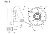
第3の特定の実施形態による計時器80が図5に示されている。計時器式モータ86と、制動部材90とを備えたアクチュエータの選択によって本質的に第1の実施形態と異なり、制動部材90は、このモータのロータ88(永久磁石を有する)に取り付けられ、制御回路40によって提供された制御信号に応じて、制動パルス中に、モータコイルの電源82によって誘導された一定の回転をロータが実行する場合、共振器6のてん輪8のフェローに一定の力を加えることができる。
A
様々な代替実施形態によれば、電気機械式アクチュエータは、圧電素子または磁歪素子、または、前記制動部材を作動させるための電磁システムを備えている。 According to various alternative embodiments, the electromechanical actuator comprises a piezoelectric or magnetostrictive element or an electromagnetic system for operating the braking member.
以下、図6および図7を参照して、本発明をもたらす開発の範囲内で強調され、本発明による計時器で実施される同期方法に関係する注目すべき物理現象を説明する。この現象を理解することにより、機械式ムーブメントの動作を調整する修正デバイスによって得られる同期をより良く理解することが可能になり、この結果が以下で詳しく説明される。 Hereinafter, with reference to FIGS. 6 and 7, notable physical phenomena related to the synchronization method performed by the timekeeper according to the present invention, which are emphasized within the scope of the development resulting in the present invention, will be described. Understanding this phenomenon makes it possible to better understand the synchronization obtained by the modifying device that coordinates the behavior of the mechanical movement, the results of which are described in detail below.
図6と図7では、最初のグラフは、制動パルスP1、P2が、問題となっている機械式共振器にそれぞれ加えられ、この共振器によって形成される、機械式振動子によってペーシングされる機構の動作を修正する時間tP1を示している。後者の2つのグラフはそれぞれ、機械式共振器の振動部材(以下「てん輪」ともいう)の経時的な角速度(毎秒のラジアンの値:[rad/s])および角度位置(ラジアンの値:[rad])を示す。曲線90、92はそれぞれ、制動パルスの発生前に自由に振動(その固有周波数における振動)するてん輪の角速度および角度位置に対応する。制動パルスが表された後、制動パルスによる外乱のあるシナリオ、および外乱のないシナリオにおける共振器の振舞いにそれぞれ対応する速度曲線90a、90bが表される。同様に、位置曲線92a、92bはそれぞれ、制動パルスによる外乱のあるシナリオ、および外乱のないシナリオにおける共振器の振舞いに対応する。これら図において、制動パルスP1、P2が発生する時間tP1、tP2は、これらのパルスの中点の時間位置に対応する。しかしながら、制動パルスの開始およびその持続時間は、時間に関して制動パルスを画定する2つのパラメータとみなされる。
In FIGS. 6 and 7, the first graph shows the mechanism by which braking pulses P1 and P2 are applied to the mechanical resonator in question, respectively, and paced by the mechanical oscillator formed by the resonator. The time t P1 to correct the operation of is shown. The latter two graphs show the angular velocity (radian per second: [rad / s]) and angular position (radian value: radian) over time of the vibrating member of the mechanical resonator (hereinafter also referred to as the "balance wheel"), respectively. [Rad]) is shown.
パルスP1、P2は、図6および図7においてバイナリ信号によって表されていることに留意されたい。しかしながら、以下の説明では、制御パルスではなく機械式共振器に加えられる機械的な制動パルスが考慮される。したがって、特定の実施形態では、特に機械式制御デバイスを有する機械式修正デバイスでは、機械的な制動パルスを加える前に、少なくとも部分的に制御パルスが発生する場合があることに留意されたい。このような場合、以下の説明では、制動パルスP1、P2は、共振器に加えられる機械的な制動パルスに対応し、以前の制御パルスには対応しない。 Note that the pulses P1 and P2 are represented by binary signals in FIGS. 6 and 7. However, in the following description, mechanical braking pulses applied to the mechanical resonator rather than control pulses are considered. Therefore, it should be noted that in certain embodiments, especially in mechanical modification devices with mechanical control devices, control pulses may be generated at least partially before applying the mechanical braking pulse. In such a case, in the following description, the braking pulses P1 and P2 correspond to the mechanical braking pulses applied to the resonator and not the previous control pulses.
さらに、制動パルスは、一定の力結合または非一定の力結合(たとえば、実質的にガウス曲線または正弦曲線)で加えられることに留意されたい。制動パルスという用語は、機械式共振器へ力結合を瞬間的に加えることを示し、機械式共振器は、その振動部材(てん輪)を制動する。すなわち、この振動部材の振動運動に対向する。可変の、ゼロではない結合の場合、パルスの持続時間は、一般に、機械式共振器を制動するための顕著な力結合を有するこのパルスの一部として画定される。制動パルスは、顕著な変動を示す場合があることに留意されたい。途切れがちの、短いパルスが連続することもあり得る。一定の結合の場合、各パルスの持続時間は、設定点1/2周期未満であり、好ましくは設定点周期の1/4よりも短い。各制動パルスは、図6および図7のように機械式共振器を停止させることなく制動をかけ得るか、制動パルス中に停止させ、この制動パルスの残りの間に、瞬間的にロックし得ることに留意されたい。
Further note that the braking pulse is applied in a constant or non-constant force coupling (eg, substantially Gaussian or sinusoidal). The term braking pulse refers to the momentary application of force coupling to a mechanical resonator, which brakes its vibrating member (balance wheel). That is, it opposes the vibrating motion of this vibrating member. For variable, non-zero couplings, the duration of the pulse is generally defined as part of this pulse with significant force coupling to brake the mechanical resonator. Note that the braking pulse may show significant variation. Short pulses, which tend to be interrupted, can be continuous. For certain binding, the duration of each pulse is less than the
機械式振動子の自由な各振動周期T0は、この機械式振動子の振動振幅を画定する2つの終了位置間でそれぞれ発生する第2の半周期A02が続く第1の半周期A01を画定し、各半周期は、同じ持続時間T0/2を有し、中央時間において、機械式共振器のゼロ位置を経由する機械式共振器の通過を示す。振動の2つの連続した半周期は、てん輪がそれぞれ一方向の振動運動を維持し、その後、他方向の振動運動を維持する2つの1/2周期を画定する。換言すれば、半周期は、振動振幅を画定するその2つの終了位置の間の一方向または他方向のてん輪の振動に対応する。原則として、制動パルスが発生する振動周期の変動、したがって機械式振動子の周波数の孤立した変動が観察される。実際、時間変動は、制動パルスが発生する唯一の半周期に関連している。「中央時間」という用語は、半周期の中間点で実質的に発生する時間を示す。これは、特に機械式振動子が自由に振動する場合である。一方、調整パルスが発生する半周期の場合、この中央時間は、調整デバイスによって引き起こされる機械式振動子の外乱により、これらの半周期のおのおのの持続時間の中間点に正確に対応しなくなる。 Free each oscillation period T0 of the mechanical oscillator, a first half period A0 1 second half period A0 2 continues to occur respectively between two end positions defining the vibration amplitude of the mechanical oscillator Defined, each half period has the same duration T0 / 2 and indicates the passage of the mechanical resonator through the zero position of the mechanical resonator in central time. The two consecutive half cycles of vibration define two 1/2 cycles in which the balance wheel maintains its vibrational motion in one direction and then the vibrational motion in the other direction. In other words, the half cycle corresponds to the vibration of the balance wheel in one or the other direction between its two end positions that define the vibration amplitude. In principle, fluctuations in the vibration period in which the braking pulse is generated, and thus isolated fluctuations in the frequency of the mechanical oscillator, are observed. In fact, time variation is associated with the only half cycle in which the braking pulse occurs. The term "central time" refers to the time that substantially occurs at the midpoint of a half cycle. This is especially the case when the mechanical oscillator vibrates freely. On the other hand, in the case of the half-cycle in which the adjustment pulse is generated, this central time does not exactly correspond to the midpoint of the duration of each of these half-cycles due to the disturbance of the mechanical oscillator caused by the adjustment device.
次に、図6に示されたものに対応する、その振動周波数の第1の修正シナリオにおける機械式振動子の振舞いを説明する。第1の周期T0後、次に、それぞれ新たな半周期A1である新たな周期T2、が始まり、この間に、制動パルスP1が発生する。初期時間tD1において半周期A1を開始すると、共振器14は、終了位置に対応する最大の正の角度位置を占める。次に、制動パルスP1は、共振器がそのニュートラル位置を通過する中央時間tN1の前に、したがって、外乱のない振動の対応する中央時間tN0の前に位置する時間tP1でも発生する。最後に、半周期A1は、終了時間tF1で終了する。制動パルスは、半周期A1の開始を示す時間tD1後の時間間隔TA1の後にトリガされる。持続時間TA1は、1/2半周期T0/4から、制動パルスP1の持続時間を引いたものよりも短い。与えられた例では、この制動パルスの持続時間は、1/2半周期T0/4よりもかなり短い。
Next, the behavior of the mechanical oscillator in the first modification scenario of its vibration frequency corresponding to that shown in FIG. 6 will be described. After the first cycle T0, a new cycle T2, which is a new half cycle A1, is started, and a braking pulse P1 is generated during this period. When the half cycle A1 is started at the initial time t D1 , the
したがって、この第1の場合では、制動パルスは、半周期の開始と、この半周期での共振器のニュートラル位置を経由する共振器の通過との間に生成される。制動パルスP1の間、絶対値での角速度は減少する。これは、角速度の2つの曲線90a、90bおよび角度位置の2つの曲線92a、92bによって、図6に示すように、共振器の振動に負の時間位相シフトTC1、すなわち、外乱のない理論信号(破線で表示)に対する遅延をもたらす。したがって、半周期A1の持続時間は、時間間隔TC1だけ増加する。したがって、半周期A1を備える振動周期T1は、値T0に対して延長される。これは、機械式振動子の周波数の孤立した減少と、関連付けられた機構の瞬間的な減速をもたらし、この機械式振動子によって、その動作が計時される。
Therefore, in this first case, the braking pulse is generated between the start of the half cycle and the passage of the resonator through the neutral position of the resonator in this half cycle. During the braking pulse P1, the absolute angular velocity decreases. This two
図7を参照して、その発振周波数の第2の修正シナリオにおける機械式振動子の振舞いを以下に説明する。第1の周期T0後、次に、それぞれ半周期A2である新たな振動周期T2が始まり、この間に、制動パルスP2が発生する。初期時間tD2において半周期A2が始まり、その後機械式共振器は、終了位置(最大の負の角度位置)にある。1/2半周期に対応する1/4周期(T0/4)の後、共振器は、中央時間tN2においてニュートラル位置に到達する。次に、制動パルスP2は、共振器がそのニュートラル位置を通過する中央時間tN2の後に、半周期A2に位置する時間tP2で発生する。最後に、制動パルスP2の後、この半周期A2は、共振器が再び終了位置(周期T2における最大の正の角度位置)を占める終了時間tF2において、したがって、外乱のない振動の対応する終了時間tF0の前でも発生する。制動パルスは、半周期A2の初期時間tD2後の時間間隔TA2の後にトリガされる。持続時間TA2は、1/2半周期T0/4よりも長く、半周期T0/2から、制動パルスP2の持続時間を引いたものよりも短い。与えられた例では、この制動パルスの持続時間は、1/2半周期よりもかなり短い。 With reference to FIG. 7, the behavior of the mechanical oscillator in the second modification scenario of the oscillation frequency will be described below. After the first cycle T0, a new vibration cycle T2, which is a half cycle A2, starts next, and a braking pulse P2 is generated during this period. At the initial time t D2 , the half cycle A2 begins, after which the mechanical resonator is in the end position (maximum negative angular position). After a quarter period (T0 / 4) corresponding to a half period, the resonator reaches the neutral position at midtime t N2. The braking pulse P2 is then generated at a time t P2 located in the half cycle A2 after a central time t N2 through which the resonator passes its neutral position. Finally, after the braking pulse P2, this half-cycle A2 is at the end time t F2 , where the resonator again occupies the end position (the maximum positive angular position in period T2), and thus the corresponding end of the undisturbed vibration. It also occurs before time t F0. The braking pulse is triggered after the time interval T A2 after the initial time t D2 of the half cycle A2. The duration T A2 is longer than 1/2 half cycle T0 / 4 and shorter than half cycle T0 / 2 minus the duration of the braking pulse P2. In the given example, the duration of this braking pulse is significantly less than 1/2 half cycle.
したがって、問題となっている第2のシナリオでは、半周期において、共振器がニュートラル位置(ゼロ位置)を通過する中央時間と、この半周期が終了する終了時間との間に、制動パルスが生成される。制動パルスP2の間、絶対値での角速度は減少する。注目すべきことに、ここでは、角速度の2つの曲線90b、90cおよび角度位置の2つの曲線92b、92cによって、図7に示されるように、制動パルスは、共振器の振動において、正の時間位相シフトTC2、すなわち、(破線で示すように)外乱のない理論信号に対する先行をもたらす。したがって、半周期A2の持続時間は、時間間隔TC2だけ減少する。したがって、半周期A2を備える振動周期T2は、値T0よりも短い。これは、機械式振動子の周波数の孤立した増加と、関連付けられた機構の瞬間的な加速をもたらし、この機械式振動子によって、その動作が計時される。この現象は驚くべきことであり、明白ではない。これが、過去に当業者がこのことを無視していた理由である。実際、制動パルスにより、機構の加速を得ることは、原理的に驚くべきことであるが、これは実際には、この動作が機械式振動子により計時され、制動パルスがその共振器に加えられる場合である。
Therefore, in the second scenario in question, a braking pulse is generated between the central time the resonator passes through the neutral position (zero position) and the end time at the end of this half cycle in the half cycle. Will be done. During the braking pulse P2, the absolute angular velocity decreases. Notably, here, by two
機械式振動子について上述した物理現象は、本発明による計時器で実施される同期方法に含まれる。計時器の分野での一般的な教示とは異なり、制動パルスで機械式振動子の周波数を低下させるのみならず、制動パルスで機械式振動子の周波数を増加させることもできる。当業者は、制動パルスを用いて、機械式振動子の周波数を実際に低下のみさせることができ、必然的に、前記振動子に電力を供給するときに、駆動パルスを加えることによって、このような機械式振動子の周波数を増加のみさせることができると期待するであろう。計時器の分野で確立され、したがって当業者が最初に思い付くようになったこのような直観的なアイデアは、機械式振動子にとって不正確であることが判明している。したがって、以下で詳細に説明するように、マスタ振動子を画定する補助振動子によって、わずかに高すぎるまたは低すぎる周波数を瞬間的に有するか否かに関わらず、さらに非常に正確な機械式振動子を同期させることが可能である。したがって、単に制動パルスによって、高すぎる周波数または低すぎる周波数を修正することが可能である。要約すると、てん輪−ヒゲゼンマイの振動の半周期中に制動結合を加えると、そのニュートラル位置を経由したてん輪−ヒゲゼンマイの通過の前または後にそれぞれ、前記制動トルクが加えられるか否かによって、このてん輪−ヒゲゼンマイの振動における負または正の位相シフトをもたらす。 The physical phenomena described above for mechanical oscillators are included in the synchronization method performed by the timekeeper according to the present invention. Unlike general teachings in the field of timewatches, braking pulses can not only reduce the frequency of mechanical oscillators, but braking pulses can also increase the frequency of mechanical oscillators. Those skilled in the art can only actually reduce the frequency of the mechanical oscillator using braking pulses, and inevitably by applying a drive pulse when powering the oscillator. You would expect to be able to only increase the frequency of the mechanical oscillator. Such an intuitive idea established in the field of timekeeping and thus first to be conceived by those skilled in the art has proved to be inaccurate for mechanical oscillators. Therefore, as described in detail below, the auxiliary oscillators that define the master oscillator allow for even more accurate mechanical vibrations, whether or not they momentarily have frequencies that are slightly too high or too low. It is possible to synchronize the children. Therefore, it is possible to correct frequencies that are too high or too low, simply by braking pulses. In summary, if a braking coupling is applied during the half cycle of the balance spring-spring vibration, the braking torque is applied before or after the passage of the balance spring-spring through its neutral position, respectively. This provides a negative or positive phase shift in the balance spring-spring vibration.
本発明によって計時器に組み込まれた修正デバイスの、結果として生じる同期方法を、以下に説明する。図8Aでは、250msの振動周期中に、300°の振幅で振動する計時器機械式共振器の角度位置(度)が示される。図8Bでは、連続的な振動周期内で制動パルスが加えられた時間にしたがって、すなわち、機械式共振器の角度位置にしたがって、機械式共振器の連続的な振動周期内で加えられた1ミリ秒(1ms)の制動パルスによって生成される毎日の誤差が示されている。ここでは、機械式振動子が、4Hzの固有周波数で自由に機能するという事実に基づく(外乱のないシナリオ)。各制動パルスによって加えられる3つの力結合(100nNm、300nNm、500nNm)に対して、それぞれ3つの曲線が与えられる。結果は、上記の物理現象、つまり、第1の1/4周期または第3の1/4周期に発生する制動パルスは、機械式振動子の周波数の低下に起因する遅延をもたらす一方、第2の1/4周期または第4の1/4周期に発生する制動パルスは、機械式振動子の周波数の増加に起因する先行をもたらすことを確認する。次に、所与の力結合について、共振器のニュートラル位置で発生する制動パルスの毎日の誤差がゼロに等しく、振動の終了位置に接近すると、この毎日の誤差は、(絶対値において)増加することが観察される。共振器の速度がゼロを通過し、動きの方向が変化するこの終了位置では、毎日の誤差の符号が突然反転する。最後に、図8Cでは、振動周期中に制動パルスが加えられた時間に応じて、上記の3つの力結合値に対して消費される制動力が与えられている。共振器の終了位置に接近すると速度が低下するため、制動力が低下する。したがって、もたらされる毎日の誤差は、終了位置に接近すると増加するが、必要な制動力(したがって、振動子によって失われるエネルギ)は大幅に減少する。 The resulting synchronization method of the modified device incorporated into the timekeeper according to the present invention will be described below. FIG. 8A shows the angular position (degrees) of a timetable mechanical resonator that vibrates with an amplitude of 300 ° during a vibration period of 250 ms. In FIG. 8B, 1 mm applied within the continuous vibration cycle of the mechanical resonator according to the time the braking pulse was applied within the continuous vibration cycle, that is, according to the angular position of the mechanical resonator. The daily error generated by the braking pulse of seconds (1 ms) is shown. Here, it is based on the fact that the mechanical oscillator functions freely at a natural frequency of 4 Hz (disturbance-free scenario). Three curves are given for each of the three force couplings (100nNm, 300nNm, 500nNm) applied by each braking pulse. The result is that the physical phenomenon described above, i.e., the braking pulse that occurs in the first quarter or third quarter, results in a delay due to the reduced frequency of the mechanical oscillator, while the second. It is confirmed that the braking pulse generated in the 1 / 4th period or the 4th 1 / 4th period of the above causes a lead due to an increase in the frequency of the mechanical oscillator. Then, for a given force coupling, the daily error of the braking pulse generated in the neutral position of the resonator is equal to zero, and as the vibration end position is approached, this daily error increases (in absolute value). Is observed. At this end position, where the resonator velocity passes zero and the direction of motion changes, the sign of the daily error suddenly reverses. Finally, in FIG. 8C, the braking force consumed for the above three force coupling values is given according to the time when the braking pulse is applied during the vibration cycle. When approaching the end position of the resonator, the speed decreases, so the braking force decreases. Therefore, the resulting daily error increases as you approach the end position, but the required braking force (and thus the energy lost by the oscillator) is significantly reduced.
図8Bにおいてもたらされる誤差は、実際には、機械式振動子が、設定点周波数に対応しない固有周波数を有するシナリオの修正に対応し得る。したがって、振動子が、低すぎる固有振動数を有する場合、振動周期の第2または第4の1/4に発生する制動パルスにより、自由な(外乱のない)振動によって採り入れられる遅延の修正が可能になる場合があり、この修正は、振動周期内の制動パルスの時間に応じてほぼ実質的である。一方、振動子が、高すぎる固有周波数を有する場合、振動周期の第1または第3の1/4に発生する制動パルスにより、自由な振動によって採り入れられる先行の修正が可能になる場合があり、この修正は、振動周期内の制動パルスの時間に応じてほぼ実質的である。 The error introduced in FIG. 8B may actually correspond to the correction of the scenario in which the mechanical oscillator has a natural frequency that does not correspond to the set point frequency. Therefore, if the oscillator has a natural frequency that is too low, the braking pulse generated in the second or fourth quarter of the vibration cycle can correct the delay taken in by the free (undisturbed) vibration. This correction is almost substantial depending on the time of the braking pulse in the vibration cycle. On the other hand, if the oscillator has a natural frequency that is too high, the braking pulse generated in the first or third quarter of the vibration cycle may allow for the preceding corrections taken in by free vibration. This modification is almost substantial depending on the time of the braking pulse in the vibration cycle.
上記で与えられた教示により、補助振動子上の主機械式振動子(スレーブ振動子)の同期の、注目すべき現象を理解することが可能となり、正の整数Nで除された設定点周波数F0Cを2倍にする、すなわち、FFR=2・F0C/Nにするために、有利に対応する制動周波数FFRで、スレーブ機械式共振器に、単に制動パルスを周期的に加えることにより、マスタ振動子を形成する。したがって、制動周波数は、マスタ振動子の設定点周波数に比例し、正の整数Nを与えられると、単にこの設定点周波数に依存する。設定点周波数は、基準周波数を乗じられた分数に等しいので、制動周波数は、基準周波数に比例し、この基準周波数によって決定される。この基準周波数は、本来、または設計によって、主機械式振動子よりもより正確である、補助振動子によって供給される。 The teachings given above make it possible to understand the notable phenomenon of synchronization of the main mechanical oscillator (slave oscillator) on the auxiliary oscillator, and the set point frequency divided by a positive integer N. Simply periodically applying a braking pulse to the slave mechanical oscillator at an advantageous corresponding braking frequency F FR in order to double F0 C , i.e. F FR = 2 · F0 C / N. To form a master oscillator. Therefore, the braking frequency is proportional to the set point frequency of the master oscillator, and when given a positive integer N, it simply depends on this set point frequency. Setpoint frequency since that is equal to the fraction which is multiplied by the reference frequency, damping frequency is proportional to the reference frequency is determined by the reference frequency. The reference frequency is originally or by design, it is more accurate than the main mechanical transducer, supplied by an auxiliary vibration Doko.
本発明によって計時器に組み込まれた修正デバイスによって得られた上述の同期は、図9から図22を活用してより詳細に説明される。 The above-mentioned synchronization obtained by the modification device incorporated in the timekeeper according to the present invention will be described in more detail with reference to FIGS. 9 to 22.
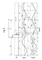
図9には、先頭グラフにおいて、自由に振動し(曲線100)、制動により振動する(曲線102)スレーブ機械式共振器、特に計時器共振器のてん輪−ヒゲゼンマイの角度位置が示されている。自由振動の周波数は、設定点周波数F0C=4Hzよりも大きい。第1の機械的な制動パルス104(以下、「パルス」とも称される)は、本明細書では、終了位置を経由する通過と、ゼロを経由する通過との間の1/2半周期における振動周期ごとに1回発生する。システムは機械式共振器の角度位置を検出しないため、この選択は任意である。したがって、これは、とりわけ、以下で分析される可能性のある仮説にすぎない。したがって、機械式振動子の減速のシナリオが、ここで観察される。本明細書では、第1の制動パルスの制動トルクは、振動周期にわたって自由な振動子によって採り入れられる先行を補償するための最小の制動トルクよりも大きいように選択される。これにより、第2の制動パルスは、これらのパルスが発生する1/4周期内で第1よりもわずかに前に生じる。機械式振動子の瞬時周波数を与える曲線106は、実際、瞬時周波数が、第1のパルスから、設定点周波数を下回ることを示している。したがって、第2の制動パルスは、先行する終了位置により近く、後続のパルスでは、制動効果が増加するという具合である。したがって、変動位相では、振動子の瞬時周波数は漸進的に低下し、パルスは、振動の終了位置に漸進的に近づく。一定時間後、制動パルスは、機械式共振器の速度が方向を変え、その後、瞬時周波数が増加し始める、終了位置を経由する通過を備えている。
FIG. 9 shows the angular position of the balance wheel-higezenmai of the slave mechanical resonator, especially the timepiece resonator, which vibrates freely (curve 100) and vibrates by braking (curve 102) in the first graph. There is. The frequency of free vibration is larger than the set point frequency F0 C = 4 Hz. The first mechanical braking pulse 104 (hereinafter, also referred to as "pulse") is used herein in a half-half cycle between passage through the end position and passage through zero. It occurs once for each vibration cycle. Because the system does not detect the angular position of the mechanical resonator, this choice is arbitrary. Therefore, this is, among other things, only a hypothesis that may be analyzed below. Therefore, the deceleration scenario of the mechanical oscillator is observed here. In this specification, the braking torque of the first braking pulse is chosen large odd than the minimum braking torque to compensate for the preceding which is adopted by the free oscillator for the oscillation period. As a result, the second braking pulse occurs slightly before the first within the quarter period in which these pulses occur. The
この制動は、共振器の動きの方向に関わらず、共振器の動きに対向することを特徴とする。したがって、共振器は、制動パルス中にその振動の方向の反転で通過するとき、制動トルクは、この反転時に、符号を自動的に変える。これは、制動トルクに、第1の符号を有する第1の部分と、第1の符号と反対の第2の符号を有する第2の部分とを有する制動パルス104aを与える。したがって、このシナリオでは、信号の第1の部分は、終了位置の前に発生し、この終了位置の後に発生する第2の部分の効果に反する。第2の部分は、機械式振動子の瞬時周波数を低下させるが、第1の部分は、増加させる。その後、振動子の瞬時周波数が(ここでは制動周波数に対応する)設定点周波数に等しい値において、最終的に比較的迅速に安定するために、修正は減少する。したがって、変動位相の後には、同期位相とも称される安定位相が続く。この場合、振動周波数は設定点周波数に実質的に等しく、制動パルスの第1および第2の部分は、実質的に一定の、画定された比率を有する。
This braking is characterized in that it opposes the movement of the resonator regardless of the direction of movement of the resonator. Therefore, when the resonator passes by reversing the direction of its vibration during the braking pulse, the braking torque automatically changes sign during this reversal. This gives the braking torque a
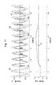
図10におけるグラフは、図9におけるグラフと同等である。主な違いは、自由な機械式振動子の固有周波数の値であり、これは、設定点周波数F0C=4Hz未満である。第1のパルス104は、図9と同じ1/2半周期において発生する。予想通り、曲線110によって与えられる瞬時周波数の減少が観察される。したがって、制動を伴う振動108は、パルス104bが終了位置を経由して共振器の通過を包含し始めるまで、変動位相において瞬間的により多くの遅延を採る。終了位置の前に発生するパルスの第1の部分は、瞬時周波数を増加させるので、この時から、設定点周波数に達するまで瞬時周波数が増加し始める。この現象は、自動的である。実際、振動周期の持続時間は、T0Cの持続時間よりも長い間、パルスの第1の部分は増加するが、第2の部分は減少し、その結果、瞬時周波数は増加し続け、設定点周期は、実質的に振動周期に等しい安定した状態になる。したがって、目的とされた同期が得られる。
The graph in FIG. 10 is equivalent to the graph in FIG. The main difference is the value of the intrinsic frequency of the free mechanical oscillator, which is less than the set point frequency F0 C = 4 Hz. The
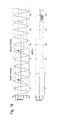
図11におけるグラフは、図10におけるグラフと同等である。主な違いは、第1の制動パルス114は、図10とは別の1/2半周期、すなわちゼロを経由する通過と、終了位置を経由する通過との間の1/2半周期において生じることである。上述したように、変動位相では、曲線112によって与えられる瞬時周波数における増加がここで観察される。本明細書では、第1の制動パルスの制動トルクは、振動周期にわたって自由な機械式振動子によって採られる遅延を補償するための最小の制動トルクよりも大きいように選択される。これにより、第2の制動パルスは、これらのパルスが発生する1/4周期内で第1よりもわずかに後に生じる。曲線112は、実際に、振動子の瞬時周波数が、第1のパルスから、設定点周波数を超えて増加することを示している。したがって、第2の制動パルスは、後続する終了位置により近く、後続のパルスでは制動効果が増加するという具合である。したがって、変動位相では、制動114を伴う振動の瞬時周波数が増加し、制動パルスは、振動の終了位置に漸進的に近づく。一定時間後、制動パルスは、機械式共振器の速度が方向を変える、終了位置を経由した通過を備えている。その時から、上記と同様の現象が観察される。制動パルス114aは、その後、2つの部分を有し、第2の部分は、瞬時周波数を低下させる。瞬時周波数におけるこの減少は、図9および図10を参照して与えられたものと同じ理由で、設定点値に等しい値になるまで続く。周波数における低下は、瞬時周波数が、設定点周波数に実質的に等しくなると、自動的に停止する。次に、同期位相における設定点周波数での機械式振動子の周波数の安定化が得られる。
The graph in FIG. 11 is equivalent to the graph in FIG. The main difference is that the
図12から図15を活用して、振動周期中に第1の制動パルスが発生する、任意の時点での、遷移位相における機械式振動子の振舞いのみならず、振動周波数が設定点周波数において安定化される同期位相に対応する最終シナリオが説明される。図12は、機械式共振器の位置の曲線S1を用いて振動周期を表している。ここで、問題になっているシナリオでは、自由な機械式振動子(制動パルスなし)の固有振動周波数F0は、設定点周波数F0Cよりも大きい(F0>F0C)。振動周期は、通常、おのおの振動振幅に対応する2つの終了位置(tm-1、Am-1;tm、Am;tm+1、Am+1)の間にある第2の半周期A2が続く第1の半周期A1を備えている。次に、第1の半周期では、中点の時間位置が、時間t1において生じる制動パルス「Imp1」が示され、第2の半周期では、中点の時間位置が、時間t2において生じるさらなる制動パルス「Imp2」が示される。パルスImp1およびImp2はT0/2の位相シフトを示し、所与の制動トルクプロファイルに対して、システムの2つの不安定な平衡をもたらす修正に対応するという特徴がある。これらのパルスはそれぞれ振動周期の第1および第3の1/4において発生するため、自由な機械式振動子の過度に高い固有周波数を正確に修正できる程度まで機械式振動子を(制動パルスを加えるために選択された制動周波数で)制動する。パルスImp1、Imp2は両方とも第1のパルスのものであり、おのおのは、他のパルスがない場合に、それ自体で考慮されることに留意されたい。パルスImp1、Imp2の効果は同一であることに留意されたい。 Utilizing FIGS. 12 to 15, not only the behavior of the mechanical oscillator in the transition phase at an arbitrary time point when the first braking pulse is generated during the vibration cycle, but also the vibration frequency is stable at the set point frequency. The final scenario corresponding to the oscillated synchronous phase is described. FIG. 12 shows the vibration period using the curve S1 of the position of the mechanical resonator. Here, in the scenario in question, the natural vibration frequency F0 of the free mechanical oscillator (without braking pulse) is larger than the set point frequency F0 C (F0> F0 C ). The vibration period is usually the second between the two end positions (tm -1 , Am-1 ; t m , Am ; t m + 1 , A m + 1 ) corresponding to each vibration amplitude. It has a first half cycle A1 followed by a half cycle A2. Next, in the first half cycle, the braking pulse "Imp1" in which the time position of the midpoint occurs at time t 1 is shown, and in the second half cycle, the time position of the midpoint occurs in time t 2. An additional braking pulse "Imp2" is shown. Pulse Imp1 and Imp2 represents a phase shift of T 0/2, there is a feature that corresponds to the modifications for a given braking torque profile, results in two unstable equilibrium of the system. Since these pulses are generated in the first and third quarters of the vibration cycle, respectively, the mechanical oscillator (braking pulse) is used to the extent that the excessively high natural frequency of the free mechanical oscillator can be accurately corrected. Braking (at the braking frequency selected to add). Note that the pulses Imp1 and Imp2 are both those of the first pulse, each of which is considered on its own in the absence of the other pulse. Note that the effects of pulses Imp1 and Imp2 are the same.
したがって、時間t1またはt2において第1のパルスが発生すると、理論的には、次の振動周期中に、このシナリオが繰り返され、振動周波数は、設定点周波数に等しくなる。このようなシナリオでは、2つの点に留意されたい。第1に、時間t1またはt2において、第1のパルスが正確に発生する可能性は比較的低いが可能である。第2に、このような特定のシナリオが発生した場合、それは長期間続くことができない。実際、計時器におけるてん輪−ヒゲゼンマイの瞬時周波数は、様々な理由(振動振幅、温度、空間的方位の変化等)により、時間の経過とともにわずかに変化する。これらの理由は、精密な腕時計製造では、一般に、最小限に抑えることが求められている外乱を表すが、実際には、このような不安定な均衡は、あまり長く続かないという事実が残っている。制動トルクが高いほど、時間t1、t2は、それぞれに続くニュートラル位置を経由した機械式共振器の2つの通過時間に近くなることに留意されたい。さらに、固有振動周波数F0と設定点周波数F0Cとの差が大きいほど、時間t1、t2はまた、それぞれに続くニュートラル位置を経由した機械式共振器の2つの通過時間に近くなることに留意されたい。 Therefore, when the first pulse is generated at time t 1 or t 2 , this scenario is theoretically repeated during the next vibration period, and the vibration frequency becomes equal to the set point frequency. Two points should be noted in such a scenario. First, at time t 1 or t 2 , it is relatively unlikely that the first pulse will occur accurately, but it is possible. Second, when such a particular scenario occurs, it cannot last for a long time. In fact, the instantaneous frequency of the balance spring-spring in the timepiece changes slightly over time for various reasons (vibration amplitude, temperature, changes in spatial orientation, etc.). These reasons represent disturbances that are generally required to be minimized in precision watchmaking, but in reality such an unstable equilibrium remains the fact that it does not last very long. There is. Note that the higher the braking torque, the closer the times t 1 and t 2 are to the two transit times of the mechanical resonator via the neutral positions that follow them. Furthermore, the greater the difference between the natural vibration frequency F0 and the set point frequency F0 C , the closer the times t 1 and t 2 are to the two transit times of the mechanical resonator via the neutral positions that follow them. Please note.
次に、パルスを加えている間に、時間位置t1またはt2からわずかに逸脱したときに、何が起こるかを検討する。図12を参照して与えられた教示によれば、ゾーンZ1a内のパルスImp1の左(先行する時間位置)にパルスが発生した場合、後続する周期中に、先行する終了位置Am-1が漸進的に制動パルスに接近するように、修正が増える。一方、パルスImp1の右(後続する時間位置)で、ゼロ位置の左にパルスが発生した場合、後続する周期中にパルスは、修正のない、このゼロ位置に向かってドリフトするように修正が減少する。実際、パルスの効果が変化し、瞬時周波数が増加する。固有周波数はすでに高すぎるため、パルスは急速に終了位置Amにドリフトする。したがって、ゾーンZ1bにおいて、パルスImp1の右にパルスが生じると、後続するパルスは、後続する終了位置Amに漸進的に接近する。同じ振舞いは、第2の半周期A2でも観察される。ゾーンZ2aのパルスImp2の左にパルスが生じると、後続するパルスは、先行する終了位置Amに漸進的に接近するであろう。一方、ゾーンZ2bにおいてパルスImp2の右にパルスが生じると、後続するパルスは、後続する終了位置Am+1に漸進的に接近するであろう。この定式化は、相対的であり、実際には、制動パルスの印加周波数は、(制動周波数を与えられると)マスタ振動子によって設定され、変動するのは振動周期となり、制動パルスの印加時間に接近するのは、問題となっている終了位置になることに留意されたい。結論として、パルスが、t1以外の時間において、第1の半周期A1で発生した場合、瞬時振動周波数は、後続する振動周期中に、変動位相において進み、この第1の半周期の2つの終了位置のうちの1つ(機械式共振器の動きの方向の反転位置)は、制動パルスに漸進的に接近するようになる。同じことは、第2の半周期A2にも当てはまる。 Next, consider what happens when the time position t 1 or t 2 deviates slightly while applying the pulse. According to the teaching given with reference to FIG. 12, when a pulse is generated to the left (preceding time position) of the pulse Imp1 in the zone Z1a, the preceding end position Am -1 is set during the subsequent cycle. The modification increases to gradually approach the braking pulse. On the other hand, if a pulse is generated to the left of the zero position on the right side of pulse Imp1 (subsequent time position), the correction is reduced so that the pulse drifts toward this zero position without correction during the subsequent cycle. To do. In fact, the effect of the pulse changes and the instantaneous frequency increases. Since the natural frequency already too high, pulses will drift rapidly end position A m. Thus, in zone Z1b, a pulse is generated to the right of the pulse imp1, subsequent pulses are progressively closer to the end position A m the subsequent. The same behavior is observed in the second half cycle A2. When a pulse is generated to the left of the pulse Imp2 zone Z2a, subsequent pulses would progressively closer to the end position A m the preceding. On the other hand, if a pulse occurs to the right of the pulse Imp2 in zone Z2b, the subsequent pulse will gradually approach the subsequent end position Am + 1. This formulation is relative, and in reality, the applied frequency of the braking pulse is set by the master oscillator (given the braking frequency), and it is the vibration cycle that fluctuates with the application time of the braking pulse. Note that the approach is the end position in question. In conclusion, if the pulse occurs in the first half-cycle A1 at a time other than t 1 , the instantaneous vibration frequency advances in the fluctuation phase during the subsequent vibration cycle, and the two of the first half-cycles. One of the end positions (the position reversing the direction of movement of the mechanical resonator) gradually approaches the braking pulse. The same applies to the second half cycle A2.
図13は、上記の変動位相の後に発生する最終的な安定状態に対応する同期位相を示す。前述のように、制動パルス中に終了位置を経由した通過が生じると、この終了位置は、場合に応じて、終了位置の直前または直後に、これらの制動パルスが構成されているすべての制動パルス(力の結合と持続時間)に揃えられ、少なくとも完全に発生する制動パルスで、自由な機械式振動子の時間ドリフトを十分に修正できるようになる。したがって、同期位相では、第1の半周期A1において第1のパルスが発生すると、振動の終了位置Am-1は、パルスImp1aに揃えられるか、振動の終了位置Amは、パルスImp1bに揃えられる。実質的に一定の結合の場合、スレーブ主振動子の高すぎる固有周波数と、マスタ補助振動子によって設定された設定点周波数との差を正確に修正できるように、パルスImp1a、Imp1bはおのおの第1の部分を有し、この持続時間は、第2の部分の持続時間よりも短い。同様に、同期位相では、第1のパルスが、第2の半周期A2おいて発生するのであれば、振動の終了位置Amは、パルスImp2aに揃えられるか、または、振動の終了位置Am+1は、パルスImp2bに揃えられる。 FIG. 13 shows the synchronous phase corresponding to the final stable state that occurs after the above-mentioned fluctuation phase. As mentioned above, when a passage through an end position occurs during a braking pulse, this end position is, as the case may be, just before or after the end position, all braking pulses that make up these braking pulses. Aligned with (force coupling and duration), at least a fully generated braking pulse, will be able to adequately correct the time drift of a free mechanical oscillator. Accordingly, the synchronous phase, the first pulse in the first half period A1 is generated, the end position A m-1 of the vibration is either aligned with the pulse Imp1a, the end position A m of the vibration, aligned with the pulse Imp1b Be done. In the case of a substantially constant coupling, the pulses Imp1a and Imp1b are each first so that the difference between the too high intrinsic frequency of the slave main oscillator and the set point frequency set by the master auxiliary oscillator can be corrected accurately. The duration of this portion is shorter than the duration of the second portion. Similarly, the synchronous phase, the first pulse, if the generated second half period A2 Oite, the end position A m of the vibration, or aligned to the pulse Imp2a, or termination of the vibration position A m +1 is aligned with the pulse Imp2b.
パルスImp1a、Imp1b,Imp2a、およびImp2bはそれぞれ、比較的安定した時間位置を占めることに留意されたい。確かに、これらのパルスの1つは、外乱により左または右にわずかにずれると、後続するパルスを、初期の相対時間位置に戻す効果を有する。その後、同期位相中に、機械式振動子の時間ドリフトが変化すると、振動はわずかな位相シフトを自動的に維持し、パルスImp1a、Imp1b,Imp2a、およびImp2bそれぞれの第1の部分と第2の部分との比は、制動パルスによってもたらされる修正を、周波数における新たな差に適応させる程度に変化する。本発明による計時器のこのような振舞いは、真に注目に値する。 Note that the pulses Imp1a, Imp1b, Imp2a, and Imp2b each occupy a relatively stable time position. Indeed, one of these pulses has the effect of returning subsequent pulses to their initial relative time position when slightly shifted to the left or right due to disturbance. Then, during the synchronous phase, as the time drift of the mechanical oscillator changes, the vibration automatically maintains a slight phase shift, with the first and second parts of the pulses Imp1a, Imp1b, Imp2a, and Imp2b, respectively. The ratio to the portion varies to the extent that the correction provided by the braking pulse is adapted to the new difference in frequency. Such behavior of the timekeeper according to the present invention is truly noteworthy.
図14および図15は、図12および図13に類似しているが、振動子の固有周波数が、設定点周波数未満であるシナリオの場合である。その結果、制動パルスによって行われた修正の不安定な平衡シナリオに対応するパルスImp3およびImp4は、それぞれ、パルスが、振動周波数の増加をもたらす第2および第4の1/4周期(時間t3および時間t4)に位置する。システムの振舞いは、先行する検討に由来するため、ここで再び詳細に説明する。変動位相(図14)において、ゾーンZ3aにおけるパルスImp3の左に、半周期A3においてパルスが生じると、先行する終了位置(tm-1、Am-1)は、後続するパルスに漸進的に接近する。一方、ゾーンZ3bにおいて、パルスImp3の右にパルスが生じると、後続する終了位置(tm、Am)は、後続するパルスに漸進的に接近する。同様に、ゾーンZ4aにおいて、パルスImp4の左に、半周期A4においてパルスが生じると、先行する終了位置(tm、Am)は、後続するパルスに漸進的に接近する。最後に、ゾーンZ4bにおいて、パルスImp4の右にパルスが生じると、後続する終了位置(tm+1、Am+1)は、遷移位相中、後続するパルスに漸進的に接近する。 14 and 15 are similar to FIGS. 12 and 13, but in the case of a scenario in which the natural frequency of the oscillator is less than the set point frequency. As a result, the pulses Imp3 and Imp4 corresponding to the modified unstable equilibrium scenario made by the braking pulse are the second and fourth quarter periods (time t 3) in which the pulse results in an increase in vibration frequency, respectively. And at time t 4 ). The behavior of the system derives from previous studies and will be discussed in more detail here. In the fluctuating phase (FIG. 14), when a pulse occurs in the half cycle A3 to the left of the pulse Imp3 in zone Z3a, the preceding end positions (tm -1 , Am-1 ) gradually move to the subsequent pulse. approach. On the other hand, in zone Z3b, the pulse to the right of the pulse Imp3 occurs, end position subsequent (t m, A m) are progressively closer to the succeeding pulse. Similarly, in the zone Z4A, the left pulse imp4, the pulses in a half cycle A4 occurs, leading end position (t m, A m) are progressively closer to the succeeding pulse. Finally, in zone Z4b, when a pulse is generated to the right of pulse Imp4, the trailing end positions (tm + 1 , Am + 1 ) gradually approach the trailing pulse during the transition phase.
同期位相(図15)において、第1の半周期A3において第1のパルスが発生すると、振動の終了位置Am-1は、パルスImp3aに揃えられるか、振動の終了位置Amは、パルスImp3bに揃えられる。実質的に一定の結合の場合、パルスImp3a、Imp3bはおのおの、スレーブ主振動子の低すぎる固有周波数と、マスタ補助振動子によって設定された設定点周波数との差を正確に修正するために、持続時間がその第2の部分の持続時間よりも長い、第1の部分を有する。同様に、同期位相において、第1のパルスは、第2の半周期A4で発生すると、振動の終了位置Amは、パルスImp4aに揃えられるか、振動の終了位置Am+1は、パルスImp4bに揃えられる。図12および図13を参照して上記で説明したシナリオの範囲内で行われるその他の検討は、図14および図15のシナリオと同様に適用される。結論として、自由な機械式振動子の固有周波数が高すぎるか低すぎるかに関わらず、振動周期内の第1の制動パルスが加えられる時間に関係なく、本発明による修正デバイスは効果的であり、機械式振動子の共振器に制動パルスが加えられる制動周波数を制御するマスタ補助振動子の基準周波数によって決定される設定点周波数において、機械式ムーブメントの動作をクロックする機械式振動子の周波数を迅速に同期させる。これは、機械式振動子の固有周波数が変化し、特定の期間では設定点周波数よりも高く、他の期間ではこの設定点周波数よりも低い場合でも、依然として正しい。 In synchronous phase (FIG. 15), the first pulse in the first half period A3 occurs, the end position A m-1 of the vibration is either aligned with the pulse Imp3a, the end position A m of the vibration, the pulse Imp3b Aligned with. In the case of a substantially constant coupling, the pulses Imp3a and Imp3b are each sustained to accurately correct the difference between the too low intrinsic frequency of the slave main oscillator and the set point frequency set by the master auxiliary oscillator. It has a first part in which the time is longer than the duration of the second part. Similarly, in the synchronous phase, the first pulse to occur in the second half cycle A4, the end position A m of the vibration is either aligned with the pulse Imp4a, end position A m + 1 of the vibration pulse Imp4b Aligned with. Other considerations made within the scenarios described above with reference to FIGS. 12 and 13 apply similarly to the scenarios of FIGS. 14 and 15. In conclusion, the modified device according to the invention is effective regardless of whether the natural frequency of the free mechanical oscillator is too high or too low, regardless of how long the first braking pulse in the vibration cycle is applied. , The frequency of the mechanical oscillator that clocks the operation of the mechanical movement at the set point frequency determined by the reference frequency of the master auxiliary oscillator that controls the braking frequency at which the braking pulse is applied to the resonator of the mechanical oscillator. Synchronize quickly. This is still true even if the intrinsic frequency of the mechanical oscillator changes and is higher than the set point frequency in certain periods and lower than this set point frequency in other periods.
上記で与えられた教示および本発明による計時器の特徴によって得られる同期は、制動パルスを加えるための制動周波数が設定点周波数に等しくないシナリオにも当てはまる。振動周期毎に1つのパルスを加える場合、不安定な位置(t1、Imp1、t2、Imp2、t3、Imp3、t4、Imp4)で発生するパルスは、単一の振動周期中に時間ドリフトを補償する修正に対応する。他方、制動パルスが、複数の振動周期中の時間ドリフトを修正するのに十分な効果を有する場合、複数の振動周期に等しい時間間隔ごとに単一のパルスを加えることが可能である。その後、振動周期ごとに1つのパルスが生成されるシナリオに関して同じ振舞いが観察される。パルスが発生する振動周期を考慮すると、上記のシナリオと同じ変動位相と、同じ同期位相とがある。さらに、これらの検討は、各制動パルスの間に、整数の半周期がある場合にも正しい。奇数の半周期の場合、場合に応じて、図12から図15における半周期A1またはA3から、半周期A2またはA4へ、遷移が交互に行われる。半周期によってオフセットされた2つのパルスの効果は同じであるため、2つの連続する制動パルス間の偶数回の半周期に関して、同期が実行されることが理解される。結論として、すでに述べたように、図12から図15を参照して説明したシステムの振舞いは、制動周波数FFRが2F0C/Nに等しくなると観察され、F0Cは、振動周波数の設定点周波数であり、Nは正の整数である。 The synchronization obtained by the teachings given above and the features of the timewatch according to the invention also applies to scenarios where the braking frequency for applying the braking pulse is not equal to the setpoint frequency. When one pulse is applied for each vibration cycle, the pulses generated at unstable positions (t 1 , Imp 1, t 2 , Imp 2, t 3 , Imp 3, t 4 , Imp 4) are timed during a single vibration cycle. Corresponds to corrections that compensate for drift. On the other hand, Braking pulse, if having sufficient effect to correct the time drift of the plurality of vibration period, it is possible to add a single pulse every time interval equal to a plurality of vibration cycles. The same behavior is then observed for scenarios where one pulse is generated for each vibration period. Considering the vibration period in which the pulse is generated, there is the same fluctuation phase and the same synchronization phase as in the above scenario. In addition, these considerations are also correct when there is an integer half cycle between each braking pulse. In the case of an odd half cycle, the transition is alternately performed from the half cycle A1 or A3 in FIGS. 12 to 15 to the half cycle A2 or A4, depending on the case. Since the effects of the two pulses offset by the half cycle are the same, it is understood that synchronization is performed for an even number of half cycles between the two consecutive braking pulses. In conclusion, as already mentioned, the behavior of the system described with reference to FIGS. 12 to 15 is observed that the braking frequency F FR is equal to 2F0 C / N, where F0 C is the set point frequency of the vibration frequency. And N is a positive integer.
あまり関心はないが、同期は、設定点周波数の2倍(2F0)より大きい制動周波数FFR、すなわちN>2の場合、F0のN倍に等しい値について得られることに留意されたい。FFR=4F0である代替実施形態では、機械式共振器のニュートラルポイントにおいて、2パルス毎に1つが発生するため、同期位相において影響を与えずにシステム内のエネルギ損失のみが存在する。より高い制動周波数FFRの場合、終了位置で発生しない同期位相におけるパルスは、その対の効果を相殺する。したがって、これらは大きな実用的な意味はない理論的なシナリオであることが理解される。 Of less interest, it should be noted that synchronization is obtained for a braking frequency F FR greater than twice the setpoint frequency (2F0), i.e. for a value equal to N times F0 when N> 2. In the alternative embodiment where F FR = 4F0, one occurs every two pulses at the neutral point of the mechanical resonator, so there is only energy loss in the system without affecting the synchronous phase. For higher braking frequencies F FR , pulses in synchronous phase that do not occur at the end position cancel out the effect of the pair. Therefore, it is understood that these are theoretical scenarios that have no great practical meaning.
図16および図17は、設定点周波数の1/4に等しい制動周波数FFRの代替実施形態のための同期位相を示し、したがって、4つの振動周期ごとに1つの制動パルスが発生する。図18および図19はそれぞれ、図16および図17の部分拡大図である。図16は、主振動子の固有周波数が、設定点周波数F0C=4Hzよりも大きいシナリオに関し、図17は、主振動子の固有周波数が、この設定点周波数よりも大きいシナリオに関する。制動パルスImp1bまたはImp2a、Imp3bまたはImp4aそれぞれが発生する振動周期T1*およびT2*のみが、固有周期T0*に対する変動を示すことが観察される。制動パルスは、対応する周期において単に位相シフトをもたらす。したがって、本明細書では、瞬時周期は、設定点周期間の平均値に等しい平均値のあたりで振動する。図16から図19では、瞬時周期は、振動信号の立ち上がりエッジでゼロを経由する通過から、このような後続する通過まで測定されることに留意されたい。したがって、終了位置において発生する同期パルスは、振動周期に完全に含まれる。包括的であるために、図20は、固有周波数が、設定点周波数に等しい特定のシナリオを示している。この場合、振動周期T0*はすべて等しいままであり、制動パルスImp5は、(一定の制動トルクの場合)同一の持続時間を有するこれらパルスの第1および第2の部分を有する自由振動の終了位置において正確に発生し、第1の部分の効果は、第2の部分の反対の効果によって相殺される。
16 and 17 show the sync phase for an alternative embodiment of the same
図21は、設定点周波数F0C=3Hzの振動周期の変化と、機械式振動子の3つの振動周期ごとに発生する、1日あたり550秒、すなわち、1日あたり約9分の毎日の誤差を示す時間表示機構の動作を計時する適切な制動パルスとを示している。この誤差は非常に顕著であるが、機械式制動デバイスは、このような誤差を修正できるように構成されている。本明細書では、制動効果は比較的顕著である必要があり、瞬時周期の大きな変動があるが、平均周期は、本発明による計時器における修正デバイスの噛合後の設定点周期と、短い変動位相とに、実質的に等しい。修正デバイスが動作していないとき、予想されるように、総時間誤差は、時間に応じて線形的に増加するのに対し、修正デバイスの噛合後に、この誤差は、急速に安定化されることが観察される。したがって、時間が、このような修正デバイスの噛合と、変動位相と後に設定された場合、(「累積誤差」とも称される)合計誤差は、低いままであるため、計時器はその後、この計時器に組み込まれ、制動デバイスに関連付けられているマスタ振動子の精度に対応する精度で時間を示す。 FIG. 21 shows a change in the vibration cycle at the set point frequency F0 C = 3 Hz and a daily error of 550 seconds per day, that is, about 9 minutes per day, which occurs for each of the three vibration cycles of the mechanical oscillator. Indicates an appropriate braking pulse for timing the operation of the time display mechanism. This error is very noticeable, but mechanical braking devices are configured to be able to correct such an error. In the present specification, the braking effect needs to be relatively remarkable and there is a large variation in the instantaneous period, but the average period is the set point period after the engagement of the correction device in the timekeeper according to the present invention and the short variation phase. And, substantially equal. As expected, when the corrective device is not operating, the total time error increases linearly with time, whereas after the corrective device meshes, this error stabilizes rapidly. Is observed. Therefore, if the time is set later with the meshing of such a correction device and the variable phase, the total error (also referred to as the "cumulative error") remains low and the timekeeper will then perform this timekeeping. The time is indicated with an accuracy that corresponds to the accuracy of the master oscillator built into the instrument and associated with the braking device.
図22は、本発明による修正デバイスの噛合後のスレーブ機械式振動子の振幅の進行を示す。変動位相では、第1のパルスがゼロ位置(ニュートラル位置)の近くで生じるシナリオにおいて、振幅における比較的明白な減少が観察される。図8Cのグラフに見られるように、特にこの変動位相の第1の部分で発生する様々な制動パルスは、比較的大きなエネルギ損失をもたらす。その後、エネルギ損失は比較的急速に減少し、最終的に同期位相における所与の修正に対して最小になる。そのため、パルスが機械式共振器の終了位置を経由した通過を含むと、振幅が増加し、同期位相の開始時に増加し続けるが、散逸した制動エネルギは、その後、機械式振動子の振幅変動に対する比較的大きな時定数が仮定されると、その最小値で安定化することが観察される。したがって、本発明によるピースはさらに、選択される制動パルスによって、振動子によって散逸されるエネルギが最小である同期位相で安定化するという利点を有する。実際、振動子は、その振幅の安定化の後、選択される制動パルスの振幅における最小の可能な減少を示す。これは、主振動子を維持しているゼンマイが解放されると、機械式ムーブメントの動作を実行するための最小振動振幅が、正確な運転を保証しながら可能な限り最新に達成されるため、利点である。したがって、本発明による同期を生成する機械式ムーブメントの動作を修正するデバイスは、パワーリザーブための最小化された影響を有する。 FIG. 22 shows the amplitude progression of the slave mechanical oscillator after meshing of the modified device according to the present invention. In the fluctuating phase, a relatively obvious decrease in amplitude is observed in the scenario where the first pulse occurs near the zero position (neutral position). As can be seen in the graph of FIG. 8C, the various braking pulses generated, especially in the first part of this variable phase, result in relatively large energy losses. The energy loss then decreases relatively rapidly and eventually minimizes for a given correction in synchronous phase. Therefore, when the pulse includes passing through the end position of the mechanical resonator, the amplitude increases and continues to increase at the start of the synchronous phase, but the dissipated braking energy is then subject to amplitude fluctuations of the mechanical oscillator. Assuming a relatively large time constant, it is observed to stabilize at its minimum. Therefore, the pieces according to the invention further have the advantage that the selected braking pulse stabilizes the energy dissipated by the oscillator in a synchronous phase that is minimal. In fact, the oscillator exhibits the smallest possible reduction in the amplitude of the selected braking pulse after its amplitude has been stabilized. This is because when the mainspring holding the main oscillator is released, the minimum vibration amplitude to perform the operation of the mechanical movement is achieved as up-to-date as possible while ensuring accurate operation. It is an advantage. Therefore, devices that modify the behavior of mechanical movements that produce synchronization according to the present invention have a minimized effect on the power reserve.
制動周波数によって生成される外乱、特に計時器ムーブメントのエネルギ損失を最小化するために、短いパルス持続時間、さらには非常に短いパルス持続時間が、好ましくは選択される。したがって、一般的な代替実施形態では、制動パルスはおのおの、設定点周期の1/400から1/10までの間の持続時間を有する。好ましい代替実施形態では、制動パルスはおのおの、前記設定点周期の1/400から1/50までの間の持続時間を有する。後者の場合、5Hzに等しい設定点周波数の場合、パルスの持続時間は、0.5ミリ秒から4ミリ秒までの間である。 Short pulse durations, even very short pulse durations, are preferably selected to minimize the disturbances produced by the braking frequency, especially the energy loss of the timekeeping movement. Therefore, in a typical alternative embodiment, each braking pulse has a duration between 1/400 and 1/10 of the set point period. In a preferred alternative embodiment, each braking pulse has a duration between 1/400 and 1/50 of the set point period. In the latter case, for a set point frequency equal to 5 Hz, the pulse duration is between 0.5 ms and 4 ms.
図1から図5を参照して、制動デバイスは、機械式共振器によって形成される機械式振動子の使用可能な動作範囲内の振動周期の実質的にいつでも、機械的な制動パルスを機械式共振器に加えることを可能にする円形制動面を有する機械式共振器を備えた計時器が説明されている。これは好ましい代替実施形態である。計時器ムーブメントは一般に、有利な連続的な外部面を備えた円形フェローを有するてん輪を有するので、上記の好ましい代替実施形態は、その機械式振動子の修正を必要とせずにこのようなムーブメントに容易に実施され得る。この好ましい代替実施形態により、変動位相の持続時間を最小化し、最適な時間内に所望の同期を実行することを可能にすると理解される。 With reference to FIGS. 1-5, the braking device mechanically produces a mechanical braking pulse at virtually any time of vibration period within the usable operating range of the mechanical resonator formed by the mechanical resonator. A timepiece with a mechanical resonator having a circular braking surface that allows it to be added to the resonator is described. This is a preferred alternative embodiment. Since the timekeeper movement generally has a balance wheel with a circular fellow with an advantageous continuous outer surface, the preferred alternative embodiment described above is such a movement without the need for modification of its mechanical oscillator. Can be easily implemented. It is understood that this preferred alternative embodiment minimizes the duration of the variable phase and makes it possible to perform the desired synchronization within the optimal time.
しかしながら、一定期間後、機械式共振器と機械式制動デバイスで形成されるシステムとの安定した同期がすでに得られている場合があり、このシステムは、機械式制動デバイスが、機械式共振器の任意の位置で、この共振器の位置の連続的または準連続的範囲でのみ周期的な制動パルスを開始できるように構成され、この範囲は、機械式共振器のニュートラル位置の両側面のうちの第1の側面において、その使用可能な動作範囲に対する機械式振動子の振幅の範囲によって定義される。有利なことに、この位置の範囲は、最小振幅の側面において、最小振幅のために、動的な乾燥摩擦によって制動パルスを可能とするように、制動パルスの持続時間に実質的に対応する角度距離まで増加される。位置が、振動周期毎に単に一度だけではなく、すべての半周期において機能できるように、このシステムは、機械式制動デバイスが、その使用可能な動作範囲に対する機械式振動子の振幅の範囲内において、前記ニュートラル位置の2つの側面のうちの第2の側面の機械式共振器の任意の位置において、周期的な制動パルスを開始できるように構成される必要がある。有利には、位置の範囲はまた、最小振幅の側面において、少なくとも制動パルスの持続時間に実質的に対応する角度距離だけ増加する。 However, after a period of time, stable synchronization between the mechanical resonator and the system formed by the mechanical resonator may have already been obtained, in which the mechanical braking device is the mechanical resonator. At any position, the periodic braking pulse can be initiated only in the continuous or quasi-continuous range of the position of this resonator, which range is of both sides of the neutral position of the mechanical resonator. In the first aspect, it is defined by the range of amplitude of the mechanical resonator with respect to its usable operating range. Advantageously, this range of positions is an angle that substantially corresponds to the duration of the braking pulse so that, on the side of the minimum amplitude, the braking pulse is allowed by dynamic dry friction due to the minimum amplitude. Increased to distance. The system allows the mechanical braking device to function within the amplitude of the mechanical oscillator with respect to its available operating range so that the position can function in all half cycles, not just once per vibration cycle. , The mechanical resonator on the second side of the two sides of the neutral position needs to be configured to be able to initiate a periodic braking pulse at any position. Advantageously, the range of positions also increases by an angular distance substantially corresponding to the duration of the braking pulse, at least in terms of minimum amplitude.
したがって、第1の一般的な代替実施形態では、機械式共振器の位置の上述した連続的または準連続的範囲は、そのニュートラル位置から2つの側面の第1の側面において、少なくとも、スレーブ機械式振動子が、この機械式振動子の使用可能な動作範囲のためにこの第1の側面において有しやすい振幅の範囲にわたって、そしてさらに有利には、振幅の範囲の最小振幅の側面において、少なくとも、制動パルスの持続時間に実質的に対応する角度距離にわたって延びる。第2の一般的な代替実施形態では、第1の連続的または準連続的範囲である第1の一般的な代替実施形態において上記で定義された連続的または準連続的範囲に加えて、上述のシステムは、スレーブ機械式振動子が、前記使用可能な動作範囲のためにこの第2の側面を有することが適切な振幅の範囲にわたって延びるこの機械式共振器の少なくとも第2の連続的または準連続的な範囲におけるそのニュートラル位置からの2つの側面のうちの第2の側面において、さらに有利なことに、少なくとも前記第1の角度距離にわたる振幅の範囲の最小振幅の側面において、制動デバイスが、機械式共振器の任意の位置において周期的な制動パルスを開始できるように構成されている。 Thus, in the first general alternative embodiment, the above-mentioned continuous or quasi-continuous range of mechanical resonator positions is at least slave mechanical in the first aspect of the two sides from its neutral position. Over the range of amplitudes that the transducer is likely to have in this first aspect due to the usable range of operation of this mechanical oscillator, and more advantageously, in the smallest amplitude aspect of the amplitude range, at least, It extends over an angular distance that substantially corresponds to the duration of the braking pulse. In the second general alternative embodiment, in addition to the continuous or quasi-continuous range defined above in the first general alternative embodiment, which is the first continuous or quasi-continuous range, described above. The system is at least a second continuous or quasi of this mechanical resonator in which the slave mechanical oscillator extends over a range of amplitudes where it is appropriate to have this second aspect for the available operating range. In the second aspect of the two aspects from its neutral position in a continuous range, more advantageously, in the smallest amplitude aspect of the amplitude range over the first angular distance, the braking device. It is configured to be able to initiate a periodic braking pulse at any position on the mechanical resonator.
強化された代替形態において、修正デバイスは、初期位相に続く通常の動作位相において、制動周波数が、複数の値、好ましくは、修正デバイスの動作の初期位相における第1の値と、第1の値よりも小さい第2の値とを採ることができるように配置されている。特に、初期位相の期間は、おそらく同期位相がすでに開始されている間に、通常の動作位相が発生するように選択される。より一般的には、初期位相は、修正デバイスの噛合に続く少なくとも第1の制動パルス、および好ましくは、ほとんどの変動位相を含む。制動パルスの周波数を増加させることによって、変動位相の持続時間が短縮される。さらに、この代替実施形態は、一方では、初期位相中に制動効率を最適化して、物理的プロセスを実行して同期をもたらし、他方では、制動エネルギ、したがって、修正デバイスが非アクティブ化されておらず、機械式ムーブメントが動作している間に維持する同期位相中における主振動子のためのエネルギ損失を最小限に抑えることを可能にする。第1の制動パルスは、共振器のニュートラル位置の近くで発生する場合があり、ここでは、主振動子の発振のためにもたらされる時間位相シフトに対する制動効果が小さくなる。一方、同期が確立されると、制動効果が最大になるこの振動の終了位置の近くで制動パルスが生じる。 In the enhanced alternative form, the modified device has a braking frequency of a plurality of values, preferably a first value and a first value in the initial phase of operation of the modified device, in the normal operating phase following the initial phase. It is arranged so that it can take a second value that is smaller than. In particular, the period of the initial phase is chosen so that the normal operating phase occurs, perhaps while the synchronous phase has already started. More generally, the initial phase includes at least the first braking pulse following the engagement of the correction device, and preferably most of the variable phase. By increasing the frequency of the braking pulse, the duration of the fluctuating phase is shortened. Moreover, this alternative embodiment, on the one hand, optimizes braking efficiency during the initial phase to perform a physical process to provide synchronization, and on the other hand, braking energy, and thus the correction device, is deactivated. Instead, it makes it possible to minimize the energy loss for the main oscillator during the synchronous phase maintained while the mechanical movement is in operation. The first braking pulse may occur near the neutral position of the resonator, where the braking effect on the time phase shift caused by the oscillation of the main oscillator is reduced. On the other hand, when synchronization is established, a braking pulse is generated near the end position of this vibration where the braking effect is maximized.
したがって、同期位相では、シナリオは堅牢であり、比較的低い制動周波数で同期の維持がすでに得られている。したがって、制動周波数は、特に計時器が外乱や衝撃を受けやすい場合に、十分な堅牢性で同期を維持しながら、同期位相において低下され得る。選択された制動周波数は、特に周囲磁場の値、計時器における温度、または加速度計による衝撃の検出のように、適切なセンサによって測定され得るスレーブ機械式振動の外部の様々なパラメータによっても変化し得ることに留意されたい。 Therefore, in synchronous phase, the scenario is robust and synchronization has already been obtained at relatively low braking frequencies. Therefore, the braking frequency can be reduced in the synchronous phase while maintaining synchronization with sufficient robustness, especially if the timekeeper is susceptible to disturbances and shocks. The selected braking frequency also varies with various external parameters of slave mechanical vibrations that can be measured by appropriate sensors, such as ambient magnetic field values, temperature in a stopwatch, or shock detection by an accelerometer. Note that you get.
最後に、本発明の範囲内で、2つの周期的な制動パルスのカテゴリは、機械式共振器に加えられる機械的な力結合の強度および周期的な制動パルスの持続時間に関して区別され得る。第1のカテゴリに関しては、機械式振動子の使用可能な動作範囲について、少なくとも上述された変動位相のほとんどにおける周期的な制動パルス中に、機械式共振器を瞬間的にロックしないように、制動トルクと制動パルスの持続時間が選択される。この場合、システムは、各制動パルス中、少なくとも任意の変動位相のほとんどにおいて、機械的な制動トルクが機械式共振器に加えられるように配置される。 Finally, within the scope of the invention, the two categories of periodic braking pulses can be distinguished with respect to the strength of the mechanical force coupling applied to the mechanical resonator and the duration of the periodic braking pulse. Regarding the first category, the usable operating range of the mechanical oscillator is braked so as not to momentarily lock the mechanical resonator during periodic braking pulses, at least in most of the above-mentioned fluctuation phases. The duration of the torque and braking pulse is selected . In this case, the system is arranged so that mechanical braking torque is applied to the mechanical cavity during each braking pulse, at least in most of any arbitrary fluctuation phase.
有利な代替実施形態では、振動部材および制動部材は、少なくとも任意の変動位相のほとんどにおいて、本質的には制動部材と、振動部材の制動面との間の動的な乾燥摩擦によって周期的な制動パルスが加えられるように配置される。第2のカテゴリに関しては、機械式振動子の使用可能な動作範囲について、および上述した同期位相において、少なくともその端部において、周期的な制動パルス中に機械式共振器をロックするように、機械的な制動トルクと、周期的な制動パルスの持続時間が選択される。 In an advantageous alternative embodiment, the vibrating member and the braking member are cycled by essentially dry dry friction between the braking member and the braking surface of the vibrating member, at least in most of any variable phase. Arranged so that a pulse is applied. With respect to the second category, with respect to the usable operating range of the mechanical oscillator, and in the synchronous phase described above, at least at its ends, the machine to lock the mechanical resonator during a periodic braking pulse. Braking torque and the duration of the periodic braking pulse are selected .
特定の代替実施形態では、同期位相では、周期的な制動パルスによって、機械式共振器の瞬間的なロックがされるが、少なくとも、周期的な制動パルスが、機械式共振器の終了位置の外側で発生する、任意の変動位相の初期部分では、機械式共振器は、これらの周期的な制動パルスによってロックされない。 In certain alternate embodiments, the synchronous phase, by periodic braking pulse, but is the instantaneous locking of the mechanical resonator, at least, a periodic braking pulse, the outer end position of the mechanical resonator In the initial part of any fluctuating phase that occurs in, the mechanical cavity is not locked by these periodic braking pulses.
Claims (20)
− 少なくとも1つの時間データアイテムの表示機構(12)と、
− その最小位置エネルギ状態に対応するニュートラル位置を中心に、一般的な振動軸に沿って振動するのに適した機械式共振器(6、6A)と、
− 前記表示機構の動作を計時するように配置された機械式振動子を前記機械式共振器とともに形成する、前記機械式共振器のメンテナンスデバイス(18)と、を備え、
前記計時器はさらに、前記機械式振動子の中間周波数を調整するためのデバイス(20、36)を備え、この調整デバイスは、前記機械式共振器の機械式制動デバイスを備え、
前記機械式制動デバイス(24、38、40、64)は、前記機械式振動子のための設定点周波数に応じてのみ選択された制動周波数において生成され、前記調整デバイスに関連付けられた補助振動子(22、42)によって決定された、周期的な制動パルス中に、前記機械式共振器に、散逸的な機械的な制動トルクを加えることができるように配置され、前記周期的な制動パルスがおのおの、前記設定点周波数の逆数に対応する設定点周期の半周期未満の持続時間を有し、前記機械式共振器および前記機械式制動デバイスで形成されたシステムは、前記機械式制動デバイスが、前記一般的な振動軸に沿った位置の範囲において、前記機械式共振器の任意の位置で、前記周期的な制動パルスを開始できるように構成され、前記範囲は、少なくとも、前記機械式振動子の使用可能な動作範囲のための前記機械式振動子が有しやすい振幅の範囲にわたって、前記機械式共振器の前記ニュートラル位置からの2つの側面のうちの少なくとも第1の側面において延びていることを特徴とする、計時器。 A timekeeper (2, 34, 62, 80) equipped with a mechanical movement (4).
-At least one time data item display mechanism (12) and
− A mechanical resonator (6, 6A) suitable for vibrating along a general vibration axis centered on the neutral position corresponding to the minimum potential energy state.
- together form the placed mechanical transducer so as to time the operation of the display mechanism and the mechanical resonator comprises a maintenance device (18) of said mechanical resonator,
The timewatch further comprises a device (20, 36) for adjusting the intermediate frequency of the mechanical oscillator, the adjusting device comprising a mechanical braking device of the mechanical resonator.
The mechanical braking device (24, 38, 40, 64) is generated at a braking frequency selected only according to a set point frequency for the mechanical transducer and is associated with the tuning device. During the periodic braking pulse determined by (22, 42), the mechanical resonator is arranged so that a dissipative mechanical braking torque can be applied, and the periodic braking pulse is generated. The system formed by the mechanical resonator and the mechanical braking device, each having a duration of less than half a cycle of the set point period corresponding to the inverse of the set point frequency, is such that the mechanical braking device is used. Within the range of positions along the general vibration axis, the periodic braking pulse can be initiated at any position of the mechanical resonator, and the range is at least the mechanical oscillator. across the mechanical oscillator tends amplitude range of which has for the available operating range of, extends at least a first side surface of the two sides from the neutral position of the mechanical resonator A timepiece that is characterized by that.
Applications Claiming Priority (5)
| Application Number | Priority Date | Filing Date | Title |
|---|---|---|---|
| EP17163248.2 | 2017-03-28 | ||
| EP17163248 | 2017-03-28 | ||
| EP17172489 | 2017-05-23 | ||
| EP17172489.1 | 2017-05-23 | ||
| PCT/EP2018/056726 WO2018177779A1 (en) | 2017-03-28 | 2018-03-16 | Timepiece comprising a mechanical movement improved by a correction device |
Publications (2)
| Publication Number | Publication Date |
|---|---|
| JP2020512558A JP2020512558A (en) | 2020-04-23 |
| JP6843268B2 true JP6843268B2 (en) | 2021-03-17 |
Family
ID=61627122
Family Applications (1)
| Application Number | Title | Priority Date | Filing Date |
|---|---|---|---|
| JP2019553304A Active JP6843268B2 (en) | 2017-03-28 | 2018-03-16 | A timekeeper with a mechanical movement whose movement is enhanced by an adjustment device |
Country Status (5)
| Country | Link |
|---|---|
| US (1) | US11300929B2 (en) |
| EP (1) | EP3602207B1 (en) |
| JP (1) | JP6843268B2 (en) |
| CN (1) | CN110520802B (en) |
| WO (1) | WO2018177779A1 (en) |
Families Citing this family (4)
| Publication number | Priority date | Publication date | Assignee | Title |
|---|---|---|---|---|
| CH715091A2 (en) | 2018-06-07 | 2019-12-30 | Swatch Group Res & Dev Ltd | Timepiece comprising a mechanical movement, the progress of which is regulated by an electromechanical device. |
| JP2023508287A (en) * | 2019-12-17 | 2023-03-02 | ザ・スウォッチ・グループ・リサーチ・アンド・ディベロップメント・リミテッド | A timepiece with a mechanical movement and a device for correcting the displayed time |
| EP3842876A1 (en) | 2019-12-24 | 2021-06-30 | The Swatch Group Research and Development Ltd | Timepiece fitted with a mechanical movement and a device for correcting the time displayed |
| EP4063973A1 (en) * | 2021-03-23 | 2022-09-28 | The Swatch Group Research and Development Ltd | Timepiece including an actuator comprising an electromechanical device |
Family Cites Families (23)
| Publication number | Priority date | Publication date | Assignee | Title |
|---|---|---|---|---|
| FR833085A (en) | 1937-02-09 | 1938-10-11 | Junghans Geb Ag | Method and device for synchronizing the regulating organ of the rate of a pendulum by means of a normal oscillator |
| CH568597B5 (en) | 1971-12-10 | 1975-10-31 | Dixi Sa | |
| CH1691872A4 (en) | 1972-11-21 | 1977-05-31 | ||
| JP2541095B2 (en) | 1993-05-31 | 1996-10-09 | 日本電気株式会社 | Laser wavelength stabilization method |
| US5533381A (en) * | 1994-06-10 | 1996-07-09 | Seale; Joseph B. | Conversion of liquid volume, density, and viscosity to frequency signals |
| JPH09138286A (en) * | 1995-11-16 | 1997-05-27 | Seiko Instr Inc | Mechanical watch with torque adjusting function |
| EP1158373A4 (en) * | 1999-12-24 | 2005-06-15 | Seiko Instr Inc | Mechanical timepiece with regulator actuating mechanism |
| EP1164441A1 (en) * | 1999-12-24 | 2001-12-19 | Seiko Instruments Inc. | Mechanical timepiece having train wheel operation controller |
| ATE363675T1 (en) | 2003-10-01 | 2007-06-15 | Asulab Sa | CLOCK WITH A MECHANICAL MOVEMENT COUPLED WITH AN ELECTRONIC REGULATOR |
| DE60314143T2 (en) * | 2003-10-01 | 2008-01-31 | Asulab S.A. | Clock with a mechanical movement, which is coupled with an electronic regulator |
| US7512391B2 (en) * | 2005-05-24 | 2009-03-31 | Freescale Semiconductor, Inc. | Self-aligning resonator filter circuit and wideband tuner circuit incorporating same |
| CN101089752A (en) | 2007-06-29 | 2007-12-19 | 北京飞天诚信科技有限公司 | Multifunction electronic watch and control method |
| EP2570870B1 (en) * | 2011-09-15 | 2016-04-06 | The Swatch Group Research and Development Ltd. | Timepiece with permanently coupled oscillators |
| CH705679B1 (en) | 2011-10-28 | 2017-01-31 | Swatch Group Res & Dev Ltd | A circuit for self-regulating the oscillation frequency of an oscillating mechanical system, and a device comprising the same. |
| CN102722099B (en) * | 2012-06-13 | 2014-06-04 | 东莞市洲进钟表有限公司 | Clock correction system with error computing function and correction method |
| JP6087895B2 (en) | 2013-12-23 | 2017-03-01 | ザ・スウォッチ・グループ・リサーチ・アンド・ディベロップメント・リミテッド | Angular velocity adjustment device for wheelset in watch movement including magnetic escapement mechanism |
| EP2998801A1 (en) * | 2014-09-19 | 2016-03-23 | The Swatch Group Research and Development Ltd. | Magnetic clock escapement and device for controlling the operation of a clock movement |
| EP2908185B1 (en) * | 2014-02-17 | 2017-09-13 | The Swatch Group Research and Development Ltd. | Device for maintaining and adjusting a clock piece resonator |
| CH709277B1 (en) * | 2014-02-17 | 2019-11-29 | Swatch Group Res & Dev Ltd | Process for the maintenance and frequency regulation of a clock resonator mechanism |
| EP2908187B1 (en) | 2014-02-17 | 2016-10-19 | The Swatch Group Research and Development Ltd. | Adjustment of a clock piece resonator by changing the active length of a hairspring |
| EP3120199B1 (en) | 2014-03-21 | 2022-12-07 | Hublot S.A., Genève | Clock oscillator |
| EP3130966B1 (en) | 2015-08-11 | 2018-08-01 | ETA SA Manufacture Horlogère Suisse | Mechanical clockwork provided with a motion feedback system |
| EP3339982B1 (en) * | 2016-12-23 | 2021-08-25 | The Swatch Group Research and Development Ltd | Regulation by mechanical breaking of a horological mechanical oscillator |
-
2018
- 2018-03-16 US US16/496,822 patent/US11300929B2/en active Active
- 2018-03-16 EP EP18710881.6A patent/EP3602207B1/en active Active
- 2018-03-16 WO PCT/EP2018/056726 patent/WO2018177779A1/en active Search and Examination
- 2018-03-16 CN CN201880022320.3A patent/CN110520802B/en active Active
- 2018-03-16 JP JP2019553304A patent/JP6843268B2/en active Active
Also Published As
| Publication number | Publication date |
|---|---|
| EP3602207B1 (en) | 2020-12-30 |
| US20200285199A1 (en) | 2020-09-10 |
| EP3602207A1 (en) | 2020-02-05 |
| CN110520802B (en) | 2021-12-07 |
| CN110520802A (en) | 2019-11-29 |
| JP2020512558A (en) | 2020-04-23 |
| US11300929B2 (en) | 2022-04-12 |
| WO2018177779A1 (en) | 2018-10-04 |
Similar Documents
| Publication | Publication Date | Title |
|---|---|---|
| JP6843268B2 (en) | A timekeeper with a mechanical movement whose movement is enhanced by an adjustment device | |
| JP6826673B2 (en) | Mechanical timekeeper with movement enhanced by adjustment device | |
| JP6523414B2 (en) | Watch assembly comprising a mechanical oscillator associated with a speed control device | |
| RU2718348C2 (en) | Mechanical clock mechanism with feedback system | |
| US10222757B2 (en) | Regulating system for a mechanical watch | |
| JP5825539B2 (en) | Magnetic resonator for mechanical clock | |
| US8770828B2 (en) | Oscillator system | |
| RU2590873C1 (en) | Adjustment of frequency of clock oscillation system by action on active length of spring balance | |
| CN110874049B (en) | Timepiece comprising a mechanical oscillator with intermediate frequency synchronized with the frequency of a reference electronic oscillator | |
| RU2629168C1 (en) | Clock synchronization mechanism | |
| JP6889220B2 (en) | A timepiece assembly with a mechanical oscillator associated with an electronic device to control the average frequency of the mechanical oscillator | |
| CN104102119A (en) | Escapement system for a balance-hairspring resonator | |
| CN102998959B (en) | Oscillators synchronized by an intermittent escapement | |
| CH713637A2 (en) | Timepiece comprising a mechanical movement whose running is improved by a correction device. | |
| US20240126214A1 (en) | Method for optimising an operation of setting and winding a watch, and device for implementation of same | |
| JP2023093365A (en) | Mechanical timepiece | |
| CN110161829A (en) | Angularly accelerate insensitive horological oscillator device to caused by wearing | |
| JP2016085220A (en) | Clock regulating system and regulation method |
Legal Events
| Date | Code | Title | Description |
|---|---|---|---|
| A521 | Request for written amendment filed |
Free format text: JAPANESE INTERMEDIATE CODE: A523 Effective date: 20191107 |
|
| A621 | Written request for application examination |
Free format text: JAPANESE INTERMEDIATE CODE: A621 Effective date: 20191107 |
|
| A131 | Notification of reasons for refusal |
Free format text: JAPANESE INTERMEDIATE CODE: A131 Effective date: 20200929 |
|
| A521 | Request for written amendment filed |
Free format text: JAPANESE INTERMEDIATE CODE: A523 Effective date: 20201228 |
|
| TRDD | Decision of grant or rejection written | ||
| A01 | Written decision to grant a patent or to grant a registration (utility model) |
Free format text: JAPANESE INTERMEDIATE CODE: A01 Effective date: 20210202 |
|
| A61 | First payment of annual fees (during grant procedure) |
Free format text: JAPANESE INTERMEDIATE CODE: A61 Effective date: 20210222 |
|
| R150 | Certificate of patent or registration of utility model |
Ref document number: 6843268 Country of ref document: JP Free format text: JAPANESE INTERMEDIATE CODE: R150 |
|
| R250 | Receipt of annual fees |
Free format text: JAPANESE INTERMEDIATE CODE: R250 |