JP6840506B2 - Image processing device, image processing method, program - Google Patents
Image processing device, image processing method, program Download PDFInfo
- Publication number
- JP6840506B2 JP6840506B2 JP2016206333A JP2016206333A JP6840506B2 JP 6840506 B2 JP6840506 B2 JP 6840506B2 JP 2016206333 A JP2016206333 A JP 2016206333A JP 2016206333 A JP2016206333 A JP 2016206333A JP 6840506 B2 JP6840506 B2 JP 6840506B2
- Authority
- JP
- Japan
- Prior art keywords
- image
- layer
- gain
- processing
- unit
- Prior art date
- Legal status (The legal status is an assumption and is not a legal conclusion. Google has not performed a legal analysis and makes no representation as to the accuracy of the status listed.)
- Active
Links
- 238000003672 processing method Methods 0.000 title claims description 3
- 238000000034 method Methods 0.000 claims description 53
- 238000000605 extraction Methods 0.000 claims description 42
- 239000002131 composite material Substances 0.000 claims description 12
- 230000002194 synthesizing effect Effects 0.000 claims description 5
- 239000000203 mixture Substances 0.000 claims description 3
- 230000015572 biosynthetic process Effects 0.000 claims 1
- 238000003786 synthesis reaction Methods 0.000 claims 1
- 238000006243 chemical reaction Methods 0.000 description 7
- 238000010586 diagram Methods 0.000 description 7
- 239000000284 extract Substances 0.000 description 5
- 230000006870 function Effects 0.000 description 5
- 238000013507 mapping Methods 0.000 description 5
- 230000000694 effects Effects 0.000 description 2
- 238000003384 imaging method Methods 0.000 description 2
- 230000007423 decrease Effects 0.000 description 1
- 238000012886 linear function Methods 0.000 description 1
- 230000003287 optical effect Effects 0.000 description 1
- 238000005192 partition Methods 0.000 description 1
- 238000011946 reduction process Methods 0.000 description 1
- 239000004065 semiconductor Substances 0.000 description 1
- 239000007787 solid Substances 0.000 description 1
Images


Classifications
-
- G—PHYSICS
- G06—COMPUTING; CALCULATING OR COUNTING
- G06T—IMAGE DATA PROCESSING OR GENERATION, IN GENERAL
- G06T3/00—Geometric image transformation in the plane of the image
- G06T3/40—Scaling the whole image or part thereof
- G06T3/4007—Interpolation-based scaling, e.g. bilinear interpolation
-
- G—PHYSICS
- G06—COMPUTING; CALCULATING OR COUNTING
- G06T—IMAGE DATA PROCESSING OR GENERATION, IN GENERAL
- G06T3/00—Geometric image transformation in the plane of the image
- G06T3/40—Scaling the whole image or part thereof
- G06T3/4053—Super resolution, i.e. output image resolution higher than sensor resolution
- G06T3/4076—Super resolution, i.e. output image resolution higher than sensor resolution by iteratively correcting the provisional high resolution image using the original low-resolution image
-
- G—PHYSICS
- G06—COMPUTING; CALCULATING OR COUNTING
- G06T—IMAGE DATA PROCESSING OR GENERATION, IN GENERAL
- G06T3/00—Geometric image transformation in the plane of the image
- G06T3/40—Scaling the whole image or part thereof
- G06T3/4015—Demosaicing, e.g. colour filter array [CFA], Bayer pattern
-
- G—PHYSICS
- G06—COMPUTING; CALCULATING OR COUNTING
- G06T—IMAGE DATA PROCESSING OR GENERATION, IN GENERAL
- G06T3/00—Geometric image transformation in the plane of the image
- G06T3/40—Scaling the whole image or part thereof
- G06T3/403—Edge-driven scaling
Description
本発明は、画像を処理する画像処理装置、画像処理方法、及びプログラムに関する。 The present invention relates to an image processing apparatus, an image processing method, and a program for processing an image.
画像の拡大及び縮小処理は、撮像装置などの画像処理装置で用いられる。一般に撮像装置では、画像をラスター方向に処理する。よって垂直方向の拡大や縮小処理において複数ラインを参照するタップ処理を行う場合には、ラインメモリが使用される。また、画像一面(1フレーム分の画像)を一度に処理する場合、ラインメモリは、画像の少なくとも水平サイズ分の大きさのメモリが必要になる。一方、近年は、撮像装置の画素数の増加や、いわゆる4k、8kなどと呼ばれている次世代ハイビジョン規格に対応するために、画像処理装置が扱う画素数は増加している。画像処理装置が扱う画素数が増加すると、ラインメモリも大きなものが必要になる。しかしながら、ラインメモリが大きくなると、コストが増えることになる。 The image enlargement / reduction process is used in an image processing device such as an image pickup device. Generally, in an image pickup apparatus, an image is processed in the raster direction. Therefore, the line memory is used when the tap processing that refers to a plurality of lines is performed in the expansion / reduction processing in the vertical direction. Further, when processing one surface of an image (an image for one frame) at a time, the line memory requires a memory having a size of at least the horizontal size of the image. On the other hand, in recent years, the number of pixels handled by an image processing device has been increasing in order to comply with the increase in the number of pixels of an image pickup device and the next-generation high-definition standard called 4k, 8k, or the like. As the number of pixels handled by the image processing device increases, a large line memory is required. However, as the line memory increases, the cost increases.
このため、画像を水平方向にブロック分割し、分割ブロック単位で処理を行うようにすることで、処理に必要なラインメモリの大きさを小さくして、コストを低減可能とした技術が提案されている。例えば特許文献1には、画像を分割ブロック単位で拡大及び縮小処理する技術が開示されている。特許文献1に記載の技術では、隣り合う分割ブロックにおいて拡大・縮小処理によるタップ処理画素数分をオーバーラップさせて入力している。この処理によって、分割ブロック毎に処理を行っても、画像一面を一度に処理した場合と同様の結果を得ることができる。 For this reason, a technique has been proposed in which the size of the line memory required for processing can be reduced and the cost can be reduced by dividing the image into blocks in the horizontal direction and performing processing in units of divided blocks. There is. For example, Patent Document 1 discloses a technique for enlarging and reducing an image in units of divided blocks. In the technique described in Patent Document 1, the number of tapped pixels by the enlargement / reduction processing is overlapped and input in the adjacent division blocks. By this processing, even if the processing is performed for each divided block, the same result as when the entire image surface is processed at one time can be obtained.
ここで、コストをさらに低減するために、例えばラインメモリをより小さくすると、ブロック分割数が増加することになり、この場合、フィルタ処理などで使用する周囲のオーバーラップ画素分だけ、トータルで処理する画素数が増加してしまう。また、ブロック分割数が増えると、分割ブロック毎に必要な制御期間が積算等されることになり、処理パフォーマンスが低下してしまう。 Here, in order to further reduce the cost, for example, if the line memory is made smaller, the number of block divisions will increase. In this case, only the surrounding overlapping pixels used in the filter processing or the like are processed in total. The number of pixels will increase. Further, if the number of block divisions increases, the control period required for each division block is integrated, and the processing performance deteriorates.
そこで、本発明は、コストの低減を実現しつつ、高い処理パフォーマンスによる画像処理を実現可能にすることを目的とする。 Therefore, an object of the present invention is to make it possible to realize image processing with high processing performance while realizing cost reduction.
本発明は、第1の階層の画像から、前記第1の階層の画像を縮小した第2の階層の画像、および、前記第2の階層の画像を縮小した第3の階層の画像を生成する生成手段と、前記第3の階層の画像のうちの、第1の領域の画像を拡大し、拡大された前記第1の領域の画像から、当該拡大された前記第1の領域の画像の一部である第2の領域の画像を抽出する抽出手段と、前記抽出された第2の領域の画像と、前記第2の階層の画像に含まれる前記第2の領域に対応する領域の画像を合成して、第1の合成画像を生成する第1の合成手段と、前記第1の合成画像を拡大し、拡大された前記第1の合成画像と、前記第1の階層の画像に含まれる前記第2の領域に対応する画像を合成して、第2の合成画像を生成する第2の合成手段と、を有し、前記第1の階層の画像と前記第2の階層の画像は、同じ数のブロックに分割されており、前記第2の領域は、前記ブロックの1つに対応する領域であることを特徴とする。 The present invention generates an image of the second layer obtained by reducing the image of the first layer and an image of the third layer obtained by reducing the image of the second layer from the image of the first layer. The image of the first region of the generation means and the image of the third layer is enlarged, and from the enlarged image of the first region, one of the enlarged images of the first region. An extraction means for extracting an image of a second region, which is a part, an image of the extracted second region, and an image of a region corresponding to the second region included in the image of the second layer. Included in the first compositing means for compositing to generate a first composite image, the first composite image in which the first composite image is enlarged and enlarged, and the image in the first layer. The image of the first layer and the image of the second layer have a second composition means for synthesizing an image corresponding to the second region to generate a second composite image, and the image of the first layer and the image of the second layer are is divided into blocks of the same number, the second region is characterized by an area corresponding to one of said blocks.
本発明によれば、コストの低減を実現しつつ、高い処理パフォーマンスによる画像処理が実現可能となる。 According to the present invention, it is possible to realize image processing with high processing performance while realizing cost reduction.
以下、図面を参照しながら、本発明の実施形態を詳細に説明する。本実施形態の画像処理装置は、デジタルカメラやデジタルビデオカメラ、カメラ機能を備えたスマートフォンやタブレット端末などの各種携帯端末、工業用カメラ、車載カメラ、医療用カメラなどの各種撮像装置に適用可能である。 Hereinafter, embodiments of the present invention will be described in detail with reference to the drawings. The image processing device of the present embodiment can be applied to various mobile terminals such as digital cameras, digital video cameras, smartphones and tablet terminals equipped with a camera function, and various imaging devices such as industrial cameras, in-vehicle cameras, and medical cameras. is there.
本実施形態の画像処理装置は、入力画像をブロック分割して、分割ブロック単位で拡大や縮小等の各種画像処理を行うことで、処理に必要なラインメモリを小さくし、コストの低減を可能としている。また、本実施形態の画像処理装置は、入力画像を2以上の複数の階層に分けて、階層毎の処理を行うことで、コストを抑えた多タップ処理を実現可能としている。階層処理では、先ず、入力画像をそれぞれ異なる複数の縮小率で縮小し、それぞれ画像の解像度で分けられる複数の階層の縮小画像が生成される。次に、下位の階層の縮小画像を一つ上位の階層の画像と同じ画像サイズに拡大し、その下位階層からの拡大画像と上位階層の画像とを加算する階層加算処理が行われる。階層処理では、このような下位階層の縮小画像を上位階層の画像と同画像サイズに拡大して、上位階層の画像と階層加算する処理を、順次上位の階層に向けて繰り返して、元の入力画像と同じ画像サイズの画像を生成する。この生成された画像は、元の入力画像と同じ画像サイズではあるが、入力画像から高周波成分が取り除かれた画像となる。そして、この高周波成分を取り除いた画像と元の画像とを加算して合成することで、周波数に依存した高度な画像処理を行うことが可能になる。階層処理が適用される具体的な処理例としては、トーンマッピング処理などが挙げられる。トーンマッピング処理では、高周波成分と低周波成分を比較し、画像のエッジ部とそれ以外のベタ部とを切り分けることで、画質を維持しながら暗部補正などのトーン補正処理を行う。この処理が多階層で行われた場合、精度よく複数の周波数成分を検出することができ、補正効果を高めることができるようになる。したがって、前述した階層処理と前述したブロック分割処理とを組み合わせた処理、すなわち、階層毎の画像をブロック分割して処理するようなことを行えば、コストを抑えつつ精度の高い補正等の画像処理が実現可能となる。 The image processing apparatus of the present embodiment divides the input image into blocks and performs various image processing such as enlargement and reduction in the divided block units, thereby reducing the line memory required for processing and reducing the cost. There is. Further, the image processing apparatus of the present embodiment can realize multi-tap processing at low cost by dividing the input image into a plurality of layers of two or more and performing processing for each layer. In the layer processing, first, the input image is reduced at a plurality of different reduction ratios, and a plurality of layers of reduced images are generated, each of which is divided by the resolution of the image. Next, a layer addition process is performed in which the reduced image in the lower layer is enlarged to the same image size as the image in the upper layer, and the enlarged image from the lower layer and the image in the upper layer are added. In the layer processing, the process of enlarging such a reduced image of the lower layer to the same image size as the image of the upper layer and adding the layer to the image of the upper layer is repeated sequentially toward the upper layer to input the original. Generate an image with the same image size as the image. The generated image has the same image size as the original input image, but the high frequency component is removed from the input image. Then, by adding and synthesizing the image from which the high frequency component has been removed and the original image, it becomes possible to perform advanced image processing depending on the frequency. Specific processing examples to which the hierarchical processing is applied include tone mapping processing and the like. In the tone mapping process, the high-frequency component and the low-frequency component are compared, and the edge portion and the other solid portion of the image are separated to perform tone correction processing such as dark portion correction while maintaining the image quality. When this process is performed in multiple layers, a plurality of frequency components can be detected with high accuracy, and the correction effect can be enhanced. Therefore, if the above-mentioned layer processing and the above-mentioned block division processing are combined, that is, if the image for each layer is divided into blocks and processed, the image processing such as highly accurate correction while suppressing the cost is performed. Becomes feasible.
ここで、前述のように階層毎に縮小画像をブロック分割して処理する場合、各分割ブロックの水平サイズ(水平方向の画素数)は、下位階層の縮小率の定数倍や一次関数にすることが多い。なぜならば、上記のようにサイズ設定することで、各分割ブロックにおける下位階層の画像サイズや開始画素位置を整数で算出することができ、さらに分割ブロック毎にメモリからの画像の読み出し位置やサイズを一定にすることができるためである。これにより、画像の読み出しや、階層処理の制御を簡易的に行うことができるため、コストを抑えつつ精度の高い処理等を実現することが可能となる。 Here, when the reduced image is divided into blocks for each layer and processed as described above, the horizontal size (number of pixels in the horizontal direction) of each divided block should be a constant multiple of the reduction rate of the lower layer or a linear function. There are many. This is because, by setting the size as described above, the image size and the start pixel position of the lower layer in each division block can be calculated by an integer, and the reading position and size of the image from the memory can be calculated for each division block. This is because it can be made constant. As a result, it is possible to easily read out the image and control the hierarchical processing, so that it is possible to realize highly accurate processing while suppressing the cost.
ただし、例えば下位階層の縮小率が小さい場合、分割ブロックのサイズの制約が大きくなることで処理パフォーマンスが低下してしまうことがある。例えば、下位階層の画像の解像度が元の入力画像の1/256の解像度であった場合、下位階層の画像サイズや開始画素位置を整数にしようとすると、元の入力画像の解像度の画像は256の倍数の水平サイズで処理する必要がある。このため、分割ブロック毎の水平サイズは、例えば十数画素単位といった細かさでは制御できない。この制約により、入力画像の画像サイズによっては、画像のブロック分割数が増える場合がある。ブロック分割数が増えると、フィルタ処理などで使用する周囲のオーバーラップ画素分だけトータルで処理する画素数が増加したり、分割ブロック毎に必要な制御期間が積算されたりすることで処理パフォーマンスが低下してしまうことになる。 However, for example, when the reduction ratio of the lower layer is small, the processing performance may be deteriorated due to the large restriction on the size of the divided block. For example, if the resolution of the lower layer image is 1/256 of the resolution of the original input image, and if the lower layer image size and start pixel position are set to integers, the image with the resolution of the original input image will be 256. Must be processed with a horizontal size that is a multiple of. Therefore, the horizontal size of each divided block cannot be controlled as finely as, for example, in units of a dozen pixels. Due to this restriction, the number of block divisions of the image may increase depending on the image size of the input image. As the number of block divisions increases, the total number of pixels to be processed increases by the amount of surrounding overlapping pixels used for filter processing, etc., and the required control period is integrated for each division block, resulting in reduced processing performance. Will be done.
本実施形態の画像処理装置は、入力画像を階層分けして階層毎にブロック分割して処理を行う場合において、分割ブロックのサイズの制約を緩和し、コストを抑えつつ精度の高い補正等の画像処理を実現可能とするために、以下の構成を備えている。 When the image processing apparatus of the present embodiment divides the input image into layers and divides the input image into blocks for each layer for processing, the restrictions on the size of the divided blocks are relaxed, and the image such as correction with high accuracy while suppressing the cost is performed. The following configurations are provided to enable processing.
<第1の実施形態>
図1は、本発明に係る画像処理装置の一適用例である第1の実施形態の撮像装置100の概略構成を示す図である。
図1に示した撮像装置100は、撮像部101、CPU102、ROM103、RAM104、DMAコントローラ105、UI部106、外部I/F部107、記録部108、画像処理部110等を有して構成されている。撮像部101は、光学系や撮像素子等を有し、画像を撮像して、その撮像画像を入力画像として取得する。CPU102は、各部の制御及び各種演算を行う。ROM103は、CPU102が各部の制御や各種処理等を実行するためのプログラムや各種パラメータ等を記憶している。RAM104は、CPU102のワークエリアや、入出力される画像データや処理途中の画像データ等の一時的な蓄積等に使用される。RAM104にはDRAMも含まれる。DMAコントローラ105は、DMA(ダイレクトメモリアクセス)を行うためのコントローラである。UI部106は、ユーザインターフェイス部であり、ユーザにより操作される各種操作デバイスやディスプレイ等の表示デバイスからなる。外部I/F部107は、画像データ等の各種データやプログラム等の通信を行うためのインターフェイス部である。記録部108は、半導体メモリカードやハードディスク等の各種記録媒体を備えるか又は着脱可能となされ、画像データ等の各種データやプログラム等が記録される。画像処理部110は、撮像部101にて取得された撮像画像、外部I/F部107、記録部108などからの入力画像等に対して、各種画像処理を行う。
<First Embodiment>
FIG. 1 is a diagram showing a schematic configuration of an
The
本実施形態では、画像処理部110により行われる画像処理の一例として、トーンマッピング処理によって入力画像に対して画素毎に異なるゲインを掛ける機能を実現する構成を例に挙げて説明する。
図1の画像処理部110において、入力画像200は、例えば撮像部101にて撮像された撮像画像から、撮像素子に起因するノイズ等が取り除かれた後の画像データであるとする。撮像部101の撮像素子は、一般にベイヤ配列と呼ばれる、赤(R),緑(G),青(B)の各色に対応して各画素が規則正しく配列されている。このため入力画像200は、ベイヤ配列の撮像素子による撮像画像に基づく画像データとなされている。また、本実施形態の場合、入力画像200のデータは、後段の処理による遅延量と合わせるために、メモリ(RAM104)に一時的に記憶された後に読み出される。なお、入力画像200は、撮像素子から出力された撮像画像データがRAM104を介さずに直接入力された画像データであってもよい。入力画像200のデータは、RAM104への一時記憶を介して、輝度変換部201と後述するゲイン乗算部209とに送られる。
In the present embodiment, as an example of the image processing performed by the
In the
輝度変換部201は、入力画像200のデータに輝度変換係数を乗算する。これにより、入力画像200は輝度画像に変換される。なお、輝度変換係数は、撮像素子におけるベイヤ配列に合わせて色ごとに与えられるとする。輝度変換部201から出力された輝度画像のデータは、ゲイン生成部202に送られる。
The
ゲイン生成部202は、輝度変換部201で生成された輝度画像のデータにゲイン係数を乗算する。これにより輝度画像はゲイン画像に変換される。本実施形態では、トーンマッピング処理を行うためのゲイン画像を生成するため、ゲイン生成部202は、輝度画像に対し、輝度値が小さいほど大きなゲインとなるようなゲイン係数を乗算する。ここでも図示は省略しているが、ゲイン生成部202で生成されたゲイン画像は、後段の処理による遅延量と合わせるためにRAM104に一時的に格納された後、読み出される。ゲイン生成部202で生成されたゲイン画像は、輝度画像に対して等倍の画像(以下、1/1ゲイン画像203と表記する。)である。本実施形態の場合、1/1ゲイン画像203は、階層処理において最も上位の階層の画像に相当する。この1/1ゲイン画像203のデータは、階層処理部207と縮小部204とに送られる。
The
縮小部204は、ゲイン生成部202から供給された1/1ゲイン画像203に対して縮小処理を行う。縮小処理の方法は公知の方法を用いることができ、詳細な説明は省略するが、例えば画像を所定の単位領域ごとに加算し、加算した画素数で正規化するなどの方法等を用いる。本実施形態の場合、縮小部204は、1/1ゲイン画像203を例えば1/16に縮小処理した1/16ゲイン画像205と、1/1ゲイン画像203を例えば1/256に縮小処理した1/256ゲイン画像206とを生成する。本実施形態の場合、1/16ゲイン画像205は中位の階層の画像の相当し、1/256画像206は最も下位の画像に相当する。縮小部204により生成された1/16ゲイン画像205のデータと1/256ゲイン画像206のデータとは、階層処理部207に送られる。なお、1/1ゲイン画像203と1/16ゲイン画像205と1/256ゲイン画像206は何れもゲイン画像であるが、縮小率が高い画像、つまり階層が下位の画像になるほど、高周波成分が取り除かれて低周波成分が残っている画像となる。
The
階層処理部207は、1/1ゲイン画像203と1/16ゲイン画像205と1/256ゲイン画像206の各階層の画像を階層加算してゲインマップ画像を生成する。階層処理部207の構成と処理の詳細については後述する。階層処理部207により生成されたゲインマップ画像のデータは、ゲイン乗算部209に送られる。
The
ゲイン乗算部209は、階層処理部207で生成されたゲインマップ画像のデータを入力画像200のデータに対して乗算することにより、出力画像210を生成する。ここで、ゲインマップ画像は、前述の輝度画像に対し、輝度値が小さいほど大きな値となるゲイン係数、つまり暗い領域ほど大きな値のゲイン係数が乗算されたゲイン画像から生成されている。したがって、このゲインマップ画像を入力画像200に乗算した場合、入力画像200の暗部に対して比較的大きなゲインが掛けられるようになり、出力画像210は、暗部補正によるトーンマッピング処理が行われた画像となる。
The
図2は、階層処理部207の詳細な構成を示す図である。
図2の階層処理部207は、第1拡大部300、ラインメモリ301、領域抽出部302、第1階層加算部303、第2拡大部304、第2階層加算部306、ラインメモリ305を有して構成されている。図2では図示していないが、第1拡大部300、領域抽出部302、第1階層加算部303、第2拡大部304、第2階層加算部306の各サブモジュールは、それぞれ図1のRAM104を介してデータの入出力が行われる。すなわち、各サブモジュールからの出力データは、それぞれ、RAM104に一時的に記憶された後に読み出されて、次の(後段の)サブモジュールに入力される。RAM104へのデータの書き込みと、RAM104からのデータの読み出しは、DMAコントローラ105による制御の下で行われる。
FIG. 2 is a diagram showing a detailed configuration of the
The
また、第1拡大部300、領域抽出部302、第1階層加算部303、第2拡大部304、第2階層加算部306の各サブモジュールには、図2に示すように制御部310〜314が設けられている。各制御部310〜314は、各々に対して予め設定されているパラメータを基に、画像をブロック分割する/しない、ブロック分割が行われる場合のブロックサイズ(画素数)や位置の制御等を行う。パラメータは、ブロック分割する/しない、ブロックサイズ及び位置、相対オフセット等を含む情報であり、それら情報が階層毎にそれぞれ設定されている。ブロック分割する/しないのパラメータは、サブモジュールにおいてブロック分割を行うか否かを表す情報として設定される。ブロックサイズ及び位置のパラメータは、サブモジュールで画像のブロック分割が行われる場合に、画像に対する各分割ブロックの位置及びブロックサイズを表す情報として設定されている。相対オフセットのパラメータは、サブモジュールで画像のブロック分割が行われる場合に、各分割ブロックの相対的な位置を表す値として設定されている。各制御部310〜314は、例えば画素カウンタを有しており、ブロック分割を行う場合には、画像の画素をカウントした画素数を基に、ブロック分割数、ブロックサイズ、位置等の制御を行う。例えば、ブロック分割が行われる場合、画素カウンタは、画像の画素数をカウントし、前述のパラメータにより設定された分割ブロックの位置及びブロックサイズに相当する画素数を区切りとしてブロック分割するような制御を行う。また、本実施形態では、DMAコントローラ105によるRAM104からのデータの読み出し時に、ブロック分割する/しないが制御される。
Further, as shown in FIG. 2,
前述したように、図2の階層処理部207において、第1拡大部300、領域抽出部302、第1階層加算部303、第2拡大部304、第2階層加算部306の各サブモジュールは、RAM104を介してデータの入出力を行うようになされている。また、それら各サブモジュールは、階層毎に設定されているパラメータを基に、各階層における画像をブロック分割する/しないが制御され、また、ブロック分割が行われる階層ではパラメータに基づくブロック分割が行われる。そして、階層処理部207は、各階層の画像(ブロック分割が行われる階層では分割ブロック毎の画像)に対して後述するような処理が行われる。以下、これらのことを踏まえた上で、図2の階層処理部207の各部の説明を行う。
As described above, in the
図2の階層処理部207において、前述した上位階層の1/1ゲイン画像203のデータは第2階層加算部306に入力される。中位階層の1/16ゲイン画像205のデータは第1階層加算部303に入力され、下位階層の1/256ゲイン画像206のデータは第1拡大部300に入力される。
In the
第1拡大部300は、1/256ゲイン画像206に対して拡大処理を行う。本実施形態では、1/256ゲイン画像206を16倍に拡大する処理を行う。詳細については後述するが、第1の実施形態の場合、1/256ゲイン画像206はブロック分割が行われずに画像全体が一括して拡大処理される。第1拡大部300における拡大処理の方法は、例えば隣接画素を用いたバイリニア補間等の処理を用いることができる。また、拡大処理の際、第1拡大部300は、ラインメモリ301に蓄積した隣接ラインのデータを用いることで垂直方向の補間をも行う。第1拡大部300において1/256ゲイン画像206が16倍に拡大処理されたゲイン画像、つまり1/16ゲイン画像のデータは、領域抽出部302に送られる。
The
領域抽出部302は、第1拡大部300で拡大処理されたゲイン画像(1/16ゲイン画像)から一部の領域を特定領域として切り出す領域抽出処理を行う。領域抽出部302における領域抽出処理は画素単位で行われる。領域抽出部302による領域抽出処理の詳細については後述する。領域抽出部302から出力されたデータは、第1階層加算部303に送られる。
The
第1階層加算部303は、前述した1/16ゲイン画像205のデータと、領域抽出部302からの出力データとを階層加算処理により合成する。本実施形態の場合、第1階層加算部303は、1/16ゲイン画像205のデータと領域抽出部302からの出力データとに対し、それぞれ一律に所定の係数比を掛けてから加算する。詳細については後述するが、第1の実施形態の場合、第1階層加算部303は、1/16ゲイン画像205をブロック分割し、その分割ブロックのデータと、領域抽出部302で抽出された特定領域のデータとを、階層加算処理により合成する。この第1階層加算部303による分割ブロック毎の階層加算処理後のデータは、第2拡大部304に送られる。
The first
第2拡大部304は、第1拡大部300と同様のバイリニア補間等の処理により、第1の階層加算部303による階層加算処理後のデータに対して16倍の拡大処理を行う。詳細については後述するが、第1の実施形態の場合、第2拡大部304は、第1の階層加算部303による分割ブロック毎の階層加算処理後のデータを16倍に拡大する処理を行う。また、第2拡大部304は、第1拡大部300の例と同様に、ラインメモリ305に蓄積した隣接ラインのデータを用いることで垂直方向の補間をも行う。第1階層加算部303による階層加算処理後のデータは1/16ゲイン画像であるため、第2拡大部304で分割ブロック毎に16倍に拡大処理された画像は、分割ブロック毎の1/1ゲイン画像となる。第2拡大部304による拡大処理で得られた分割ブロック毎の1/1ゲイン画像のデータは、第2階層加算部306に送られる。
The
第2階層加算部306は、前述した1/1ゲイン画像203のデータと、第2拡大部304から供給された1/1ゲイン画像のデータとを階層加算処理により合成する。本実施形態の場合、第2階層加算部306は、1/1ゲイン画像203のデータと第2拡大部304から供給された1/1ゲイン画像のデータとに対し、第1階層加算部303と同様にそれぞれ一律に所定の係数比を掛けてから加算する。詳細については後述するが、第1の実施形態の場合、第2階層加算部306は、1/1ゲイン画像203をブロック分割し、その分割ブロックのデータと、第2拡大部304からの分割ブロック毎の1/1ゲイン画像とを、階層加算処理により合成する。そして、第2階層加算部306は、階層加算処理後の全ての分割ブロックのデータを、図1のゲイン乗算部209に出力する。
The second
以下、本実施形態において、階層処理部207で使用されているラインメモリ(301,305)に必要となるメモリサイズ(容量)と、画像を一度に処理できる最大水平画素数とについて説明する。ここで、階層処理部207において、画像を一度に処理できる水平の最大画素数は例えば1000画素であるとする。ただし、階層処理部207が画像を一度に処理できる水平の最大画素数は、ラインメモリのサイズに依存する。また、ラインメモリのサイズは、拡大処理が行われる前の画像の水平サイズ以上あればよい。例えばラインメモリ305の場合は、階層処理部207内の各サブモジュールのうち第2拡大部304による拡大処理前の1/16ゲイン画像のラインのデータを蓄積する。このため、ラインメモリ305は、階層処理部207が一度に処理できる水平最大画素数(1000)を、1/16ゲイン画像の水平サイズ(16)で割った値(1000÷16=62.5)≒63画素のサイズのメモリであればよい。一方、ラインメモリ301には、第1拡大部300に入力される画像、つまりブロック分割されていない画像が供給される。ブロック分割されていない画像は、入力画像200の画角に相当する画像であるが、第1拡大部300に入力されるのは前述したように1/1ゲイン画像が1/256に縮小された1/256ゲイン画像である。したがって、入力画像200の水平方向の最大サイズが例えば8000画素であった場合、ラインメモリ301は、最大サイズ(8000)を1/256で割ったサイズ、つまり8000÷256=31.25≒32画素のサイズのメモリであればよい。
Hereinafter, in the present embodiment, the memory size (capacity) required for the line memory (301, 305) used in the
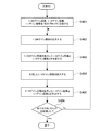
次に、図3と図4のフローチャートを用いて、図2の階層処理部207で行われる処理の流れについて説明する。なお、以下の説明の場合、これらのフローチャートの処理は、図1や図2のハードウェア構成により実行されているが、CPU等がプログラムを実行することにより実現されてもよい。
第1の実施形態の場合、階層処理部207は、上位階層の1/1ゲイン画像203と中位階層の1/16ゲイン画像205についてはブロック分割を行い、下位階層の1/256ゲイン画像206についてはブロック分割を行わないようになされている。ここでは、ブロック分割と処理の内容を分かりやすく示すために、先ず、図3のフローチャートを参照して、上位階層と中位階層だけなく下位階層をも含む全階層が同じ分割ブロック数に分割されて処理される例について説明する。すなわち、図3のフローチャートは、全階層で同じ分割ブロック数へのブロック分割が行われて、それら分割ブロック毎に拡大処理と階層加算処理が行われる場合の処理の流れを示している。
Next, the flow of processing performed by the
In the case of the first embodiment, the
図3のステップS401において、階層処理部207の第1拡大部300は、入力された1/256ゲイン画像206をx個のブロックに分割する。同様に、第1階層加算部303は、入力された1/16ゲイン画像205をx個のブロックに分割し、第2階層加算部306は、入力された1/1ゲイン画像203をx個のブロックに分割する。ステップS401の後、階層処理部207の処理はステップS402に進む。以下のステップS402からステップS406までの処理は分割ブロック毎に順次行われる。
In step S401 of FIG. 3, the
ステップS402では、第1拡大部300は、分割ブロックの1/256ゲイン画像206に対し16倍の拡大処理を行って1/16ゲイン画像を生成する。ステップS402の後、階層処理部207の処理は、第1階層加算部303にて行われるステップS403に進む。なお、図3のフローチャートの場合、領域抽出部302は、第1拡大部300での拡大処理により生成された分割ブロックの1/16ゲイン画像を、そのままスルー処理して第1階層加算部303に出力する。
In step S402, the
ステップS403では、第1階層加算部303は、分割ブロックの1/16ゲイン画像205と、第1拡大部300で16倍拡大処理された分割ブロックの1/16ゲイン画像とを、分割ブロック単位の階層加算処理により合成する。ステップS403の後、階層処理部207の処理は、第2拡大部304にて行われるステップS404に進む。
In step S403, the first
ステップS404では、第2拡大部304は、第1階層加算部303での階層加算処理により合成された分割ブロックの1/16ゲイン画像を16倍に拡大処理する。ステップS404の後、階層処理部207の処理は、第2階層加算部306にて行われるステップS405に進む。
In step S404, the
ステップS405では、第2階層加算部306は、分割ブロックの1/1ゲイン画像203と、第2拡大部304での16倍拡大処理による分割ブロックの1/1ゲイン画像とを、分割ブロック単位の階層加算処理により合成する。ステップS405の後、第2階層加算部306は、ステップS406に処理を進める。
In step S405, the second
ステップS406では、第2階層加算部306は、全ての分割ブロックに対する処理が終わったか否かを判定し、未処理の分割ブロックが残っている場合には、ステップS402に処理を戻す。これにより、階層処理部207では、未処理の分割ブロックに対して、ステップS402〜405の処理が行われることになる。一方、第2階層加算部306は、ステップS406において全ての分割ブロックの処理が完了したと判定した場合、階層処理部207における階層処理が完了したとして、図3のフローチャートの処理を終了する。
In step S406, the second
この図3の例のように、全階層を同じ分割ブロック数に分割した場合には、分割ブロック毎に、順次、下位の階層から拡大処理を行って一つ上位の階層の画像と合成し、さらにその階層の画像を拡大処理して上位の階層の画像と合成するという処理を繰り返す。なお、この例では、階層数が3階層の例を示しているが、階層数が例えば2階層や4階層以上でも同様の処理が行われることになる。 When all the layers are divided into the same number of divided blocks as in the example of FIG. 3, each divided block is sequentially enlarged from the lower layer and combined with the image of the next higher layer. Further, the process of enlarging the image of the layer and synthesizing it with the image of the upper layer is repeated. In this example, the number of layers is three, but the same processing is performed even if the number of layers is, for example, two layers or four or more layers.
図3のフローチャートでは、全階層が同じ分割ブロック数に分割されて処理される例を説明したが、第1の実施形態の場合には、上位階層と中位階層についてブロック分割を行い、一方、下位階層についてはブロック分割を行わないようになされている。図4のフローチャートは、第1の実施形態における処理の流れを示している。すなわち、図4のフローチャートでは、1/16ゲイン画像205と1/1ゲイン画像203はブロック分割されて処理されるが、1/256ゲイン画像206はブロック分割されずに画像全体が一括で処理される。
In the flowchart of FIG. 3, an example in which all layers are divided into the same number of divided blocks and processed has been described, but in the case of the first embodiment, the upper layer and the middle layer are divided into blocks, while the upper layer and the middle layer are divided into blocks. Block division is not performed for the lower layers. The flowchart of FIG. 4 shows the flow of processing in the first embodiment. That is, in the flowchart of FIG. 4, the 1/16
図4のステップS501において、階層処理部207の第1階層加算部303は、入力された1/16ゲイン画像205をx個のブロックに分割し、また、第2階層加算部306は、入力された1/1ゲイン画像203をx個のブロックに分割する。一方、図4のステップS501において、第1拡大部300は、1/256ゲイン画像206についてはブロック分割を行わない。ステップS501の後、階層処理部207の処理はステップS502に進む。以下のステップS502からステップS507までの処理は分割ブロック毎に順次行われる。
In step S501 of FIG. 4, the first
ステップS502では、第1拡大部300は、ブロック分割されていない1/256ゲイン画像206に対して16倍の拡大処理を行って1/16ゲイン画像を生成する。ステップS502の後、階層処理部207の処理は、領域抽出部302にて行われるステップS503に進む。
In step S502, the
ステップS503では、領域抽出部302は、第1拡大部300で拡大処理された1/16ゲイン画像から一部の領域を特定領域として抽出する。具体的には、領域抽出部302は、第1拡大部300で拡大処理された1/16ゲイン画像から、1/16ゲイン画像205の分割ブロックのサイズ及び位置に対応した画像領域を、特定領域として抽出する。ステップS504の後、階層処理部207の処理は、第1階層加算部303にて行われるステップS504の処理に進む。
In step S503, the
ステップS504では、第1階層加算部303は、分割ブロックの1/16ゲイン画像205と、領域抽出部302にて抽出された特定領域の画像とを、階層加算処理により合成する。ステップS504の後、階層処理部207の処理は、第2拡大部304にて行われるステップS505に進む。
In step S504, the first
ステップS505では、第2拡大部304は、第1階層加算部303での階層加算処理により合成された分割ブロックの1/16ゲイン画像を16倍に拡大処理する。ステップS505の後、階層処理部207の処理は、第2階層加算部306にて行われるステップS506に進む。
In step S505, the
ステップS506では、第2階層加算部306は、分割ブロックの1/1ゲイン画像203と、第2拡大部304で16倍拡大処理された分割ブロックの1/1ゲイン画像とを、階層加算処理により合成する。ステップS506の後、第2階層加算部306は、ステップS507に処理を進める。
In step S506, the second
ステップS507では、第2階層加算部306は、全ての分割ブロックに対する処理が終わったか否かを判定し、未処理の分割ブロックが残っている場合には、ステップS502に処理を戻す。これにより、階層処理部207では、未処理の分割ブロックに対して、ステップS502〜507の処理が行われることになる。すなわち図4のフローチャートの場合、領域抽出部302には、第1拡大部300による拡大処理後の1/16ゲイン画像が、上位側の階層(つまり中位階層)における分割ブロック数に相当する回数だけRAM104から読み出されて入力されることになる。そして、領域抽出部302では、RAM104から読み出された1/16ゲイン画像から、中位階層における分割ブロックのサイズ及び位置に対応した特定領域を抽出する処理が行われる。
In step S507, the second
第2階層加算部306は、ステップS507において全ての分割ブロックの処理が完了したと判定した場合、階層処理部207における階層処理が完了したとして、図4のフローチャートの処理を終了する。
When the second
以下、前述したような第1の実施形態における上位階層と中位階層のブロック分割処理と、下位階層の画像に対する特定領域の抽出処理について説明する。
図5(a)〜図5(c)は、第1の実施形態における画像のブロック分割処理と特定領域の抽出処理の考え方を説明するための図である。
図5(a)は前述した1/1ゲイン画像203に対するブロック分割の概要を、図5(b)は1/16ゲイン画像205に対するブロック分割の概要を、図5(c)は1/256ゲイン画像206に対する拡大処理と特定領域の抽出処理の概要を表す図である。図5(a)〜図5(c)の例では、水平方向の分割数が"5"であり、分割ブロック数x=5となされている例を挙げている。なお本実施形態では、垂直方向の分割は行われていないが、本実施形態は垂直方向に分割する場合も同様に可能である。
Hereinafter, the block division processing of the upper layer and the middle layer and the extraction process of the specific area for the image of the lower layer will be described in the first embodiment as described above.
5 (a) to 5 (c) are diagrams for explaining the concept of the block division process of the image and the extraction process of the specific region in the first embodiment.
FIG. 5A is an outline of the block division for the 1/1
本実施形態において、図5(a)に示した1/1ゲイン画像203の各分割ブロックB1〜B4における水平サイズ(水平方向の画素数)の画素数制約は16の倍数としている。したがって、1/1ゲイン画像203の各分割ブロックB1〜B4における水平サイズは、"n"を自然数として、16n,32n,48n,64nのように表される。なお、各分割ブロックB1〜B4の水平サイズの画素数制約は、本実施形態のような階層処理が行われる場合の階層数や、コーデック形式など様々な要因に応じて決められる数値である。また、1/1ゲイン画像203の分割ブロックB5は、1/1ゲイン画像203を各分割ブロックB1〜B4で分割した際の余りの領域からなるブロックであるため、水平サイズは16の倍数でなくてもよい。この1/1ゲイン画像203の各分割ブロックB1〜B5の水平方向の開始座標は、前述した16n毎のブロックの区切りの位置となる。
In the present embodiment, the pixel number constraint of the horizontal size (the number of pixels in the horizontal direction) in each of the divided blocks B1 to B4 of the 1/1
また、図5(b)に示した1/16ゲイン画像205は、1/1ゲイン画像203を1/16に縮小した画像である。このため、1/16ゲイン画像205の各分割ブロックB1〜B4の水平サイズ及び開始座標は、1/1ゲイン画像203の例の1/16で16n÷16=nとなり、それぞれn,2n,3n,4nのように表される。すなわち、1/16ゲイン画像205の各分割ブロックB1〜B4の水平サイズは整数となり、開始座標も整数で等間隔となるため、例えばRAM104における画像データの読み出し制御が複雑になることはない。なお、1/16ゲイン画像205の分割ブロックB5は、1/16ゲイン画像205を各分割ブロックB1〜B4で分割した際の余りの領域からなるブロックである。
Further, the 1/16
一方、図5(c)に示した1/256ゲイン画像206は、前述したように画像全体を16倍する拡大処理が行われた後、上位側の階層(中位階層)の分割ブロックの処理が行われる毎に、RAM104から画像全体が一括して読み出される。すなわち、下位階層ではブロック分割が行われていないため、下位階層において拡大処理された1/16ゲイン画像は、上位側の階層(中位階層)における分割ブロックの水平サイズに相当する画角の領域より広い画角の領域に相当した画像となる。そして、領域抽出部302は、第1拡大部300で拡大処理されてRAM104から読み出された1/16ゲイン画像から、1/16ゲイン画像206の分割ブロックに対応した特定領域のみを抽出する。例えば領域抽出部302は、1/16ゲイン画像205で1ブロック目の分割ブロックB1が処理される際には、1/256ゲイン画像206の拡大処理後の1/16ゲイン画像から、1/16ゲイン画像205の分割ブロックB1に対応した特定領域B1を抽出する。領域抽出部302は、1/16ゲイン画像205で2ブロック目の分割ブロックB2が処理される際には、1/256ゲイン画像206の拡大処理後の1/16ゲイン画像から、1/16ゲイン画像205の分割ブロックB2に対応した特定領域B2を抽出する。以下同様である。すなわち、領域抽出部302が抽出する特定領域の開始座標及び水平サイズは、1/16ゲイン画像205の各分割ブロックに対応した開始座標及び水平サイズと同じになされる。なお、1/256ゲイン画像206の拡大処理後の1/16ゲイン画像から特定領域が抽出された後の残りの領域は、後段の第1階層加算部303での階層加算処理の際には不要であるためカットされる(使用されずに削除される)。
On the other hand, the 1/256
図6(a)〜図6(c)は、具体的な数値を挙げて画像のブロック分割と特定領域の抽出の考え方を説明するための図である。図5(a)〜図5(c)の例と同様に、図6(a)は1/1ゲイン画像203の分割ブロック、図6(b)は1/16ゲイン画像205の分割ブロック、図6(c)は1/256ゲイン画像206の拡大処理と特定領域を表している。
6 (a) to 6 (c) are diagrams for explaining the concept of block division of an image and extraction of a specific region by giving specific numerical values. Similar to the examples of FIGS. 5 (a) to 5 (c), FIG. 6 (a) is a divided block of the 1/1
図6(a)に示した1/1ゲイン画像203の画像全体の水平サイズ(水平方向の画素数)は4688画素であるとする。また、1/1ゲイン画像203の各分割ブロックB1〜B4の水平サイズは、前述した最大水平画素数の1000以下で且つ16の倍数である992画素とする。ただし、1/1ゲイン画像203の各分割ブロックB1〜B4による分割後の余りの分割ブロックB5の水平サイズは720画素になっている。この図6(a)の例の場合、各分割ブロックB1〜B5のそれぞれの読み出し開始位置は、水平方向の画素数に換算するとそれぞれ"0","992","1984","2976","3968"のように整数となる。なお、これら読み出し開始位置の画素数は、前述した画素カウンタによりカウントされる画素数に相当する。
It is assumed that the horizontal size (the number of pixels in the horizontal direction) of the entire image of the 1/1
また、図6(b)に示す1/16ゲイン画像205の場合、画像全体の水平サイズは、1/1ゲイン画像203の画像全体の水平サイズ(4688)の1/16であるため、4688÷16=293画素となる。また、1/16ゲイン画像205における各分割ブロックB1〜B4の水平サイズは、1/1ゲイン画像203の分割ブロックの水平サイズ(922)の1/16であるため、992÷16=62画素になる。なお、1/16ゲイン画像205の各分割ブロックB1〜B4による分割後の余りの分割ブロックB5の水平サイズは45画素になっている。したがって、1/16ゲイン画像205における各分割ブロックB1〜B5のそれぞれの読み出し開始位置は、"0","62","124","186","248"のように整数となる。
Further, in the case of the 1/16
一方、図6(c)に示す1/256ゲイン画像206の画像全体の水平サイズは、1/1ゲイン画像203の画像全体の水平サイズ(4688)の1/256であるため、4688÷256=18.3画素となり、小数値を繰り上げることで19画素となる。なお、図6(c)の1/256ゲイン画像206において、図中斜線で示す領域は、繰上げにより増やした領域を表している。ここで例えば、1/256ゲイン画像206に対して、1/1ゲイン画像203や1/16ゲイン画像205と同様に例えば5分割によるブロック分割を行う場合について考えてみる。この場合、1/256ゲイン画像206を5分割した各分割ブロックB1〜B4の水平サイズは3.875画素になり、小数値が存在することになる。なお、1/256ゲイン画像206の分割ブロックB5の水平サイズは、19画素から各分割ブロックB1〜B4を除いた余りと図中斜線で示す領域とを合わせたサイズとなり、小数値が存在するサイズとなる。このように、各分割ブロックの水平サイズに小数値が存在すると、分割ブロック単位でRAM104から画像を読み出す処理が非常に複雑になってしまう。
On the other hand, the horizontal size of the entire image of the 1/256
これに対し、第1の実施形態では、前述したように1/256ゲイン画像206についてはブロック分割を行わずに画像全体を一括してRAM104から読み出すようにしているため、前述のような小数値を扱う必要がない。第1の実施形態では、前述のように、第1拡大部300にて1/256ゲイン画像206を16倍に拡大処理した後、領域抽出部302において、1/16ゲイン画像205の各分割ブロックに合わせたサイズ及び位置から特定領域を抽出している。すなわち下位階層の拡大処理後の1/16ゲイン画像は、中位階層の分割ブロック相当の画角より広い画角相当の画像であり、特定領域は、この下位階層の拡大処理後の1/16ゲイン画像の中から、中位階層の分割ブロックの画角相当の領域として抽出される。具体的には、特定領域は、1/16ゲイン画像205の各分割ブロックの読み出し開始位置に合った整数の画素数で表される位置で抽出される。図6(c)の例では、1/16ゲイン画像205の分割ブロックB2(62画素から124画素までの分割ブロック)に対応した特定領域が抽出されている例を表している。この図6(c)の例の場合、特定領域は、1/256ゲイン画像206を16倍に拡大処理した1/16ゲイン画像の中の62画素から124画素までの間の領域となる。なお、特定領域が抽出された後の残りの領域は、後段の階層加算処理では不要であるためカットされる。
On the other hand, in the first embodiment, as described above, for the 1/256
このように、第1の実施形態では、下位側の階層の画像については、その階層に対して一つ上位側の階層に合わせた拡大処理がなされた後、その拡大処理後の画像から、上位側の階層の分割ブロックの水平サイズ及び開始座標に対応した特定領域が抽出される。そして、領域抽出された特定領域の画像と、上位側の階層の分割ブロックの画像とが階層加算されて合成される。このため、第1の実施形態では、画素位置の計算を整数で行うことができ、RAM104からの読み出し処理が非常に容易になる。すなわち、第1の実施形態によれば、サイズの小さいラインメモリを使用可能にすることによるコストの低減を実現することのみならず、RAM104からの読み出し処理を容易にすることによる高い処理パフォーマンスの画像処理が実現可能となる。
As described above, in the first embodiment, the image in the lower layer is enlarged by one layer higher than the image in the lower layer, and then the image after the enlargement process is displayed in the upper layer. A specific area corresponding to the horizontal size and start coordinates of the division block of the side hierarchy is extracted. Then, the image of the specific area extracted from the area and the image of the divided block of the upper layer are layered and combined. Therefore, in the first embodiment, the pixel position can be calculated with an integer, and the reading process from the
図7(a)〜図7(c)は、入力画像200の水平方向の最大サイズが例えば8000画素であった場合に階層毎のブロック分割数の例を説明するための図である。また、図8(a)〜図8(c)は、入力画像200の水平方向の最大サイズが例えば8000画素であった場合において、第1の実施形態における上位階層及び中位階層のブロック分割数と、下位階層の画像の例を説明するための図である。なお、図7(a)〜図7(c)の例は、第1の実施形態に係る図8の例との対比に用いる図であり、全階層において同じ分割数でブロック分割が行われた場合を示している。図7(a)と図8(a)は1/1ゲイン画像203を、図7(b)と図8(b)は1/16ゲイン画像205を、図7(c)と図8(c)は1/256ゲイン画像206を示している。
7 (a) to 7 (c) are diagrams for explaining an example of the number of block divisions for each layer when the maximum size of the
図7(a)〜図7(c)と図8(a)〜図8(c)において、1/1ゲイン画像203の水平サイズは前述したように8000画素である。このため、1/16ゲイン画像205の水平サイズは8000÷16=500画素となり、1/256ゲイン画像206の水平サイズは8000÷256=31.25で小数値を繰り上げて32画素とする。また、図7(a)〜図7(c)と図8(a)〜図8(c)において、1/1ゲイン画像203を一度に処理できる水平サイズは例えば最大で1000画素であるとする。
In FIGS. 7 (a) to 7 (c) and 8 (a) to 8 (c), the horizontal size of the 1/1
図7(a)〜図7(c)において、1/1ゲイン画像203を一度に処理できる水平サイズは最大1000画素であるため、1/256ゲイン画像206の分割ブロックの水平サイズを整数にするためには256で割り切れるという画素数の制約が生ずる。この制約の下、図7(a)に示すように、1/1ゲイン画像203をブロック分割した場合の水平サイズの最大値は768画素となる。同様に、図7(b)に示すように、1/16ゲイン画像205の分割ブロックの水平サイズは768÷16=48で48画素となり、図7(c)に示すように、1/256ゲイン画像206の分割ブロックの水平サイズは768÷256=3で3画素になる。したがって、図7(a)〜図7(c)の例では、各階層の分割ブロック数はそれぞれ11ブロックとなる。
In FIGS. 7 (a) to 7 (c), since the maximum horizontal size that can process the 1/1
一方、第1の実施形態では前述したように上位階層と中位階層ではブロック分割を行うが、下位階層ではブロック分割が行われない。また、1/1ゲイン画像203を一度に処理できる水平サイズは最大1000画素であるとする。第1の実施形態の場合、ブロック分割されるのは1/1ゲイン画像203と1/16ゲイン画像205であり、1/256ゲイン画像206はブロック分割されない。図8(a)〜図8(c)の例では、1/16ゲイン画像205の分割ブロックの水平サイズが整数になる必要があるため、1/1ゲイン画像203をブロック分割した場合の水平サイズの最大値は、16で割り切れる最大値である992画素となる。また、1/16ゲイン画像205の各分割ブロックの水平サイズは、992÷16=62で62画素となる。これらのことから、第1の実施形態の場合は、図8(a)と図8(b)に示すように、1/1ゲイン画像203と1/16ゲイン画像205の分割ブロック数は9ブロックとなる。一方、図8(c)に示すように、1/256ゲイン画像206は画像全体を一括で読み出すためブロック分割されず、前述したように、中位階層の1/16ゲイン画像205の分割ブロック数に相当する回数だけRAM104から読み出される。すなわち、図8(a)〜図8(c)の場合、図7(a)〜図7(c)のように全階層で同じ分割数でブロック分割を行う場合と比較して、分割数を少なくすることができる。
On the other hand, in the first embodiment, as described above, the block division is performed in the upper layer and the middle layer, but the block division is not performed in the lower layer. Further, it is assumed that the maximum horizontal size that can process the 1/1
なお、前述の実施形態では1/1、1/16、1/256の三つの階層による階層処理の例を示したが、更に多くの階層で処理を行う場合も容易に適応可能である。この場合、それら多数の階層を中間で二つの階層群に分け、上位側の各階層を上位階層群、下位側の各階層を下位階層群とする。上位階層群では分割ブロック単位で処理を行い、下位階層群ではブロック分割を行わない。また、下位階層群については、拡大処理して上位階層群の画像との階層加算を行う手前で、その上位階層群の分割ブロックに合わせた特定領域を抽出する。そして、それら上位階層群の分割ブロックと、拡大処理された下位階層群から抽出された特定領域とを階層加算する。この例のように、三つ以上の多数の階層で処理を行う場合にも、本実施形態は適用可能であり、前述同様の効果が期待できる。 In the above-described embodiment, an example of hierarchical processing using three layers of 1/1, 1/16, and 1/256 is shown, but it can be easily applied when processing is performed in more layers. In this case, these many layers are divided into two layer groups in the middle, each layer on the upper side is a higher layer group, and each layer on the lower side is a lower layer group. In the upper layer group, processing is performed in units of divided blocks, and in the lower layer group, block division is not performed. Further, with respect to the lower layer group, a specific area corresponding to the divided block of the upper layer group is extracted before the layer addition with the image of the upper layer group is performed by the enlargement processing. Then, the divided blocks of the upper layer group and the specific area extracted from the expanded lower layer group are hierarchically added. As in this example, the present embodiment can be applied even when processing is performed in a large number of layers of three or more, and the same effect as described above can be expected.
前述したように、本実施形態の階層処理部207は、階層毎に分けられた画像の拡大処理と階層加算を行う際、階層毎にブロック分割する/しないを制御し、下位側の階層ではブロック分割を行わず、上位側の階層ではブロック分割を行うようにする。そして、階層処理部207は、ブロック分割しない下位側の階層で拡大処理した画像から、上位側の階層の分割ブロックに対応した特定領域を抽出し、その特定領域の画像と、上位側の階層の分割ブロックとで階層加算を行う。これにより、本実施形態によれば、各階層の画像をブロック単位に分割して処理する際に、分割ブロックの水平サイズの画素数の制約を緩和して分割ブロック数をより少なくすることができ、処理パフォーマンス向上させることができる。
As described above, the
また、前述した実施形態では、階層処理を行う例を挙げたが、画像を分割ブロック単位で処理する場合において、階層処理以外で例えば拡大処理を含む様々な機能にも適用可能である。例えば、二つの画像の待ち合わせ処理を行い、加減算処理やテンプレートマッチング処理などが行われる場合においても、分割数の制約や緩和を行うことができる。 Further, in the above-described embodiment, the example of performing the hierarchical processing is given, but when the image is processed in units of divided blocks, it can be applied to various functions including, for example, enlargement processing other than the hierarchical processing. For example, even when the two images are matched and addition / subtraction processing, template matching processing, or the like is performed, the number of divisions can be restricted or relaxed.
この場合においても、階層加算以外の部分においては前述同様の制御を行えばよく、画像の読み出しは一括で行い、拡大処理の後に分割ブロックに合わせた特定領域を抽出するという処理は同様である。このとき、領域抽出部で抽出される特定領域に対応し、拡大処理前の画像の端部の画素の位置が小数値で表される位置になる場合には、少なくともその位置を含む整数となる画素の位置から読み出すようにする。また、この場合の拡大処理における拡大率は、拡大後の端部の画素の位置が整数となる倍率であればよい。 Also in this case, the same control as described above may be performed in the portion other than the layer addition, and the process of reading out the images in a batch and extracting the specific area according to the divided block after the enlargement process is the same. At this time, if the position of the pixel at the end of the image before the enlargement processing corresponds to the specific area extracted by the area extraction unit and is a position represented by a decimal value, it is at least an integer including that position. Read from the pixel position. Further, the enlargement ratio in the enlargement processing in this case may be a magnification in which the positions of the pixels at the end after the enlargement are integers.
<第2の実施形態>
前述した第1の実施形態では、下位階層の1/256ゲイン画像206はブロック分割せずに画像全体を一括でRAM104から読み出して処理を行う例を示した。第2の実施形態では、1/256ゲイン画像206についてもブロック分割し、分割ブロック単位で必要な領域のみを読み出す例について説明する。なお、第2の実施形態の撮像装置は前述の図1の撮像装置100と同じ構成であり、また、画像処理部110の階層処理部207も前述の図2と同じ構成であるため、それらの図示と説明は省略する。第2の実施形態の場合、第1拡大部300は1/256ゲイン画像206をブロック分割し、分割ブロック毎に16倍の拡大処理を行う。
<Second embodiment>
In the first embodiment described above, the 1/256
図9は、第2の実施形態において1/256ゲイン画像206をブロック分割した場合の分割ブロック毎のRAM104からの読み出しについての説明に用いる図である。図9の例では、図示を省略しているが、1/1ゲイン画像203と1/16ゲイン画像205は、例えば前述した図5(a)と図5(b)や図6(a)と図6(b)に示したようにそれぞれ5ブロックに分割されているとする。また、1/256ゲイン画像206は、図6(c)の所で説明したように、各分割ブロックB1〜B4と分割ブロックB5のように5ブロックに分割されるとする。
FIG. 9 is a diagram used for explaining reading from the
第2の実施形態のように1/256ゲイン画像206を分割ブロックB1〜B5に分割した場合、各分割ブロックにおいて後段の処理で必要な画素の先頭または最後の位置は、図6(c)で説明したように画素数に換算して小数値で表される位置になる。このため、第2の実施形態の場合、RAM104から1/256ゲイン画像206の各分割ブロックB1〜B5のデータを読み出す際には、少なくとも小数値で表される位置を含む整数位置から、画像の読み出しが行われる。
When the 1/256
具体的に説明すると、1/256ゲイン画像206において、分割ブロックB1の水平方向の先頭位置は整数位置(0)なので、分割ブロックB1の水平方向の先頭位置からそのまま読み出しが行われる。一方、分割ブロックB1の水平方向の最後の位置は画素数換算で3.875なので、3.875を含み、かつ、画素数が大きい方向の整数位置である4画素目までが読み出される。次に、分割ブロックB2の先頭位置は画素数換算で3.875なので、3.875を含み、かつ、画素数が小さい方向の整数位置である3画素目からの読み出しが行われる。一方、分割ブロックB2の最後の位置は画素数換算で7.75なので、7.75を含み、かつ、画素数が大きい方向の整数位置である8画素目までが読み出される。以下、同様にして、それぞれの分割ブロックB3〜B5について、それぞれ先頭又は最後の位置の小数値を含むように画像の読み出しが行われる。そして、第1拡大部300は、前述したように分割ブロックB1〜B5に対してそれぞれ小数値を含む整数位置までの余剰分を有する領域について、16倍の拡大処理を行った後、領域抽出部302に出力する。すなわち第2の実施形態において、下位階層における分割ブロックに余剰分を含めた領域は、上位側の階層(中位階層)における分割ブロックの水平サイズに相当する画角より広い画角に相当した領域となる。
Specifically, in the 1/256
第2の実施形態の領域抽出部302は、前述のように分割ブロックに余剰分を含めた領域が16倍に拡大処理された1/16ゲイン画像から、余剰分に相当する領域をカットする。そして、領域抽出部302は、そのカット後の分割ブロックの1/16ゲイン画像のデータを、第1積層加算部303に出力する。第1積層加算部303以降の各部の処理は第1の実施形態の場合と同様であるため、その説明は省略する。
The
このように、第2の実施形態の場合、前述したように分割ブロックB1〜B5に対して、それぞれ小数値を含む整数位置までの余剰分が含まれた領域の読み出しが行われる。すなわち、第2の実施形態において、第1拡大部300からは、上位側の階層(中位階層)における分割ブロックの水平サイズに相当する画角より広い画角に相当した領域を拡大した画像が出力される。また、領域抽出部302では、分割ブロックに余剰分を含めた領域が16倍に拡大処理された1/16ゲイン画像から、余剰分に相当する領域をカットしている。このため、第2の実施形態の場合、1/256ゲイン画像206の読み出し位置や読み出しサイズ、及び、領域抽出部302においてカットする領域が分割ブロック毎に異なることになる。例えば、図9の例の場合、分割ブロックB1では余剰分を含む読み出し時の水平サイズは4画素であるのに対し、分割ブロックB2〜B4では5画素、分割ブロックB5では3画素となる。このため、第2の実施形態の場合は、前述したブロック分割の際のパラメータの設定を制御することにより、1/256ゲイン画像206の読み出し位置や読み出しサイズ、領域抽出部302におけるカットする領域を変更可能としている。具体的には、図9の例の場合、分割ブロックB1では余剰分を含む4画素分の領域を分割ブロックのサイズ及び位置とするようなパラメータを設定する。同様に、分割ブロックB2〜B4では余剰分を含む5画素分の領域を分割ブロックのサイズ及び位置とし、分割ブロックB5では余剰分を含む3画素分の領域を分割ブロックのサイズ及び位置とするようなパラメータをそれぞれ設定する。これにより図9の例に示したような読み出しが可能となる。
As described above, in the case of the second embodiment, as described above, the divided blocks B1 to B5 are read out from the region including the surplus up to the integer position including the decimal value. That is, in the second embodiment, from the
前述したように、第2の実施形態によれば、1/256ゲイン画像206の各分割ブロックB1〜B5において小数値の画素位置を扱う必要がなく、また、1/256ゲイン画像206の各分割ブロックB1〜B5の読み出し量は必要最小限で済むことになる。したがって、第2の実施形態の場合は、前述した第1の実施形態のように1/256ゲイン画像206の画像全体が一括して読み出される場合と比較して、画像の読み出し量を削減することができる。第2の本実施形態においても同様に、コストの低減を実現しつつ、高い処理パフォーマンスの画像処理が実現可能となる。
As described above, according to the second embodiment, it is not necessary to handle the pixel position of the decimal value in each of the division blocks B1 to B5 of the 1/256
以上説明したように、第1の実施形態及び第2の実施形態によれば、画像を階層毎にブロック分割して処理を行う際に、画素数の制約を緩和することができる。また、第1の実施形態で説明した処理を採用すれば、パラメータの変更などの制御をより単純にした処理が可能となる。一方、第2の実施形態で説明した処理を採用した場合には、画像の読み出し量を、より少なくすることができる。第1、第2の実施形態の何れにおいても、分割ブロック数を従来の処理よりも少なくすることができ、処理パフォーマンス向上させることができる。 As described above, according to the first embodiment and the second embodiment, it is possible to relax the restriction on the number of pixels when the image is divided into blocks for each layer and processed. Further, if the process described in the first embodiment is adopted, it is possible to perform a process in which control such as changing a parameter is simplified. On the other hand, when the process described in the second embodiment is adopted, the amount of reading the image can be further reduced. In any of the first and second embodiments, the number of divided blocks can be reduced as compared with the conventional processing, and the processing performance can be improved.
<その他の実施形態>
本発明は、上述の実施形態の1以上の機能を実現するプログラムを、ネットワーク又は記憶媒体を介してシステム又は装置に供給し、そのシステム又は装置のコンピュータにおける1つ以上のプロセッサがプログラムを読出し実行する処理でも実現可能である。また、1以上の機能を実現する回路(例えば、ASIC)によっても実現可能である。
<Other Embodiments>
The present invention supplies a program that realizes one or more functions of the above-described embodiment to a system or device via a network or storage medium, and one or more processors in the computer of the system or device reads and executes the program. It can also be realized by the processing to be performed. It can also be realized by a circuit (for example, ASIC) that realizes one or more functions.
上述の実施形態は、何れも本発明を実施するにあたっての具体化の例を示したものに過ぎず、これらによって本発明の技術的範囲が限定的に解釈されてはならないものである。即ち、本発明は、その技術思想、又はその主要な特徴から逸脱することなく、様々な形で実施することができる。 The above-described embodiments are merely examples of embodiment in carrying out the present invention, and the technical scope of the present invention should not be construed in a limited manner by these. That is, the present invention can be implemented in various forms without departing from the technical idea or its main features.
201 輝度変換部、202 ゲイン生成部、204 縮小部、207 階層処理部、209 ゲイン乗算部、300 第1拡大部、301,305 ラインメモリ、302 領域抽出部、303 第1階層加算部、304 第2拡大部、306 第2階層加算部、310〜314 制御部 201 Luminance conversion unit, 202 gain generation unit, 204 reduction unit, 207 layer processing unit, 209 gain multiplication unit, 300 first expansion unit, 301, 305 line memory, 302 area extraction unit, 303 first layer addition unit, 304th 2 expansion unit, 306 second layer addition unit, 310-314 control unit
Claims (5)
前記第3の階層の画像のうちの、第1の領域の画像を拡大し、拡大された前記第1の領域の画像から、当該拡大された前記第1の領域の画像の一部である第2の領域の画像を抽出する抽出手段と、
前記抽出された第2の領域の画像と、前記第2の階層の画像に含まれる前記第2の領域に対応する領域の画像を合成して、第1の合成画像を生成する第1の合成手段と、
前記第1の合成画像を拡大し、拡大された前記第1の合成画像と、前記第1の階層の画像に含まれる前記第2の領域に対応する画像を合成して、第2の合成画像を生成する第2の合成手段と、を有し、
前記第1の階層の画像と前記第2の階層の画像は、同じ数のブロックに分割されており、
前記第2の領域は、前記ブロックの1つに対応する領域であることを特徴とする画像処理装置。 A generation means for generating an image of the second layer obtained by reducing the image of the first layer and an image of the third layer obtained by reducing the image of the second layer from the image of the first layer.
Among the images of the third layer, the image of the first region is enlarged, and the enlarged image of the first region is a part of the enlarged image of the first region . An extraction means for extracting an image of two regions and
A first composition that generates a first composite image by synthesizing the extracted image of the second region and the image of the region corresponding to the second region included in the image of the second layer. Means and
The first composite image is enlarged, and the enlarged first composite image and the image corresponding to the second region included in the image of the first layer are combined to form a second composite image. Has a second synthetic means, which produces
The image of the first layer and the image of the second layer are divided into the same number of blocks.
The second region, the image processing apparatus which is a region corresponding to one of said blocks.
前記第1の領域に対応する画像のサイズは、整数の画素数で表されることを特徴とする請求項1または2に記載の画像処理装置。 The size of the image corresponding to the second region included in the image of the third layer is represented by the number of pixels including a decimal value.
The image processing apparatus according to claim 1 or 2, wherein the size of the image corresponding to the first region is represented by an integer number of pixels.
前記第3の階層の画像のうちの、第1の領域の画像を拡大し、拡大された前記第1の領域の画像から、当該拡大された前記第1の領域の画像の一部である第2の領域の画像を抽出する抽出工程と、
前記抽出された第2の領域の画像と、前記第2の階層の画像に含まれる前記第2の領域に対応する領域の画像を合成して、第1の合成画像を生成する第1の合成工程と、
前記第1の合成画像を拡大し、拡大された前記第1の合成画像と、前記第1の階層の画像に含まれる前記第2の領域に対応する画像を合成して、第2の合成画像を生成する第2の合成工程と、を有し、
前記第1の階層の画像と前記第2の階層の画像は、同じ数のブロックに分割されており、
前記第2の領域は、前記ブロックの1つに対応する領域であることを特徴とする画像処理方法。 A generation step of generating an image of the second layer obtained by reducing the image of the first layer and an image of the third layer obtained by reducing the image of the second layer from the image of the first layer.
Among the images of the third layer, the image of the first region is enlarged, and the enlarged image of the first region is a part of the enlarged image of the first region . Extraction process to extract the image of 2 areas and
A first composition that generates a first composite image by synthesizing the extracted image of the second region and the image of the region corresponding to the second region included in the image of the second layer. Process and
The first composite image is enlarged, and the enlarged first composite image and the image corresponding to the second region included in the image of the first layer are combined to form a second composite image. Has a second synthesis step, which produces
The image of the first layer and the image of the second layer are divided into the same number of blocks.
Said second region, an image processing method which is a region corresponding to one of said blocks.
Priority Applications (2)
| Application Number | Priority Date | Filing Date | Title |
|---|---|---|---|
| JP2016206333A JP6840506B2 (en) | 2016-10-20 | 2016-10-20 | Image processing device, image processing method, program |
| US15/787,138 US10475159B2 (en) | 2016-10-20 | 2017-10-18 | Image processing apparatus, image processing method, and storage medium storing program to scale image having hierarchical layer |
Applications Claiming Priority (1)
| Application Number | Priority Date | Filing Date | Title |
|---|---|---|---|
| JP2016206333A JP6840506B2 (en) | 2016-10-20 | 2016-10-20 | Image processing device, image processing method, program |
Publications (3)
| Publication Number | Publication Date |
|---|---|
| JP2018067849A JP2018067849A (en) | 2018-04-26 |
| JP2018067849A5 JP2018067849A5 (en) | 2019-11-28 |
| JP6840506B2 true JP6840506B2 (en) | 2021-03-10 |
Family
ID=61969739
Family Applications (1)
| Application Number | Title | Priority Date | Filing Date |
|---|---|---|---|
| JP2016206333A Active JP6840506B2 (en) | 2016-10-20 | 2016-10-20 | Image processing device, image processing method, program |
Country Status (2)
| Country | Link |
|---|---|
| US (1) | US10475159B2 (en) |
| JP (1) | JP6840506B2 (en) |
Families Citing this family (3)
| Publication number | Priority date | Publication date | Assignee | Title |
|---|---|---|---|---|
| JP6554253B2 (en) * | 2017-06-05 | 2019-07-31 | 楽天株式会社 | IMAGE PROCESSING APPARATUS, IMAGE PROCESSING METHOD, AND IMAGE PROCESSING PROGRAM |
| JP6869841B2 (en) * | 2017-07-20 | 2021-05-12 | キヤノン株式会社 | Image processing device, control method of image processing device, and program |
| CN112258396B (en) * | 2020-12-17 | 2021-04-06 | 恒银金融科技股份有限公司 | Method for scaling character image |
Family Cites Families (8)
| Publication number | Priority date | Publication date | Assignee | Title |
|---|---|---|---|---|
| JP3549720B2 (en) * | 1998-01-28 | 2004-08-04 | シャープ株式会社 | Image processing device |
| WO2011052117A1 (en) * | 2009-10-26 | 2011-05-05 | 株式会社ソニー・コンピュータエンタテインメント | Image file generation device, image processing device, image file generation method, image processing method, and data structure for image files |
| JP5419822B2 (en) * | 2010-07-23 | 2014-02-19 | 株式会社ソニー・コンピュータエンタテインメント | Image processing apparatus, image display apparatus, image processing method, and data structure of image file |
| WO2012035691A1 (en) * | 2010-09-13 | 2012-03-22 | 株式会社ソニー・コンピュータエンタテインメント | Image processing device, image processing method, data structure for video files, data compression device, data decoding device, data compression method, data decoding method, and data structure for compressed video files |
| JP5703769B2 (en) | 2011-01-19 | 2015-04-22 | ソニー株式会社 | Image conversion apparatus, image conversion method, program, and electronic apparatus |
| JP5792607B2 (en) * | 2011-12-09 | 2015-10-14 | 株式会社ソニー・コンピュータエンタテインメント | Image processing apparatus and image processing method |
| US8675999B1 (en) * | 2012-09-28 | 2014-03-18 | Hong Kong Applied Science And Technology Research Institute Co., Ltd. | Apparatus, system, and method for multi-patch based super-resolution from an image |
| US9984440B2 (en) * | 2013-06-18 | 2018-05-29 | Adobe Systems Incorporated | Iterative patch-based image upscaling |
-
2016
- 2016-10-20 JP JP2016206333A patent/JP6840506B2/en active Active
-
2017
- 2017-10-18 US US15/787,138 patent/US10475159B2/en active Active
Also Published As
| Publication number | Publication date |
|---|---|
| US20180114292A1 (en) | 2018-04-26 |
| US10475159B2 (en) | 2019-11-12 |
| JP2018067849A (en) | 2018-04-26 |
Similar Documents
| Publication | Publication Date | Title |
|---|---|---|
| JP6706985B2 (en) | Image processing apparatus and control method thereof | |
| JP4063306B1 (en) | Image processing apparatus, image processing method, and program | |
| JP6840506B2 (en) | Image processing device, image processing method, program | |
| US20140375843A1 (en) | Image processing apparatus, image processing method, and program | |
| US9462189B2 (en) | Piecewise perspective transform engine | |
| US9311691B2 (en) | Method and device for processing a super-resolution image | |
| US8902474B2 (en) | Image processing apparatus, control method of the same, and program | |
| EP2421239B1 (en) | Image processing apparatus and method for applying film grain effects | |
| JP2017045273A (en) | Image processing apparatus, image processing method, and program | |
| KR102470242B1 (en) | Image processing device, image processing method and program | |
| JP7183015B2 (en) | Image processing device, image processing method, and program | |
| JP4212430B2 (en) | Multiple image creation apparatus, multiple image creation method, multiple image creation program, and program recording medium | |
| JP4265363B2 (en) | Image processing device | |
| JP5836789B2 (en) | Image processing apparatus, control method therefor, and program | |
| JP5337250B2 (en) | Image processing apparatus and method | |
| JP2020057242A (en) | Image processing system, image processing method, and program | |
| JP4265362B2 (en) | Image processing device | |
| JP4904013B2 (en) | Image generation program and image generation apparatus | |
| JP5414384B2 (en) | Image processing apparatus, image processing method, and program | |
| JP4087010B2 (en) | Image processing device | |
| JP2009205610A (en) | Image classification device, image classification method, image classification program, and recording medium | |
| JP2006303693A (en) | Electronic camera provided with function of generating reduced picture | |
| JP2016095667A (en) | Image processing device and electronics apparatus | |
| JP4316476B2 (en) | Image processing apparatus and image forming apparatus | |
| JP6465669B2 (en) | Image processing apparatus and image processing method |
Legal Events
| Date | Code | Title | Description |
|---|---|---|---|
| A521 | Request for written amendment filed |
Free format text: JAPANESE INTERMEDIATE CODE: A523 Effective date: 20191015 |
|
| A621 | Written request for application examination |
Free format text: JAPANESE INTERMEDIATE CODE: A621 Effective date: 20191015 |
|
| A977 | Report on retrieval |
Free format text: JAPANESE INTERMEDIATE CODE: A971007 Effective date: 20200807 |
|
| A131 | Notification of reasons for refusal |
Free format text: JAPANESE INTERMEDIATE CODE: A131 Effective date: 20200818 |
|
| A521 | Request for written amendment filed |
Free format text: JAPANESE INTERMEDIATE CODE: A523 Effective date: 20200930 |
|
| TRDD | Decision of grant or rejection written | ||
| A01 | Written decision to grant a patent or to grant a registration (utility model) |
Free format text: JAPANESE INTERMEDIATE CODE: A01 Effective date: 20210119 |
|
| A61 | First payment of annual fees (during grant procedure) |
Free format text: JAPANESE INTERMEDIATE CODE: A61 Effective date: 20210217 |
|
| R151 | Written notification of patent or utility model registration |
Ref document number: 6840506 Country of ref document: JP Free format text: JAPANESE INTERMEDIATE CODE: R151 |