JP6839963B2 - Anomaly detection method, anomaly detection device and anomaly detection system - Google Patents
Anomaly detection method, anomaly detection device and anomaly detection system Download PDFInfo
- Publication number
- JP6839963B2 JP6839963B2 JP2016212574A JP2016212574A JP6839963B2 JP 6839963 B2 JP6839963 B2 JP 6839963B2 JP 2016212574 A JP2016212574 A JP 2016212574A JP 2016212574 A JP2016212574 A JP 2016212574A JP 6839963 B2 JP6839963 B2 JP 6839963B2
- Authority
- JP
- Japan
- Prior art keywords
- vehicle
- unit
- bus
- feature information
- determination
- Prior art date
- Legal status (The legal status is an assumption and is not a legal conclusion. Google has not performed a legal analysis and makes no representation as to the accuracy of the status listed.)
- Active
Links
Images


Classifications
-
- H—ELECTRICITY
- H04—ELECTRIC COMMUNICATION TECHNIQUE
- H04L—TRANSMISSION OF DIGITAL INFORMATION, e.g. TELEGRAPHIC COMMUNICATION
- H04L12/00—Data switching networks
- H04L12/28—Data switching networks characterised by path configuration, e.g. LAN [Local Area Networks] or WAN [Wide Area Networks]
- H04L12/40—Bus networks
-
- G—PHYSICS
- G06—COMPUTING; CALCULATING OR COUNTING
- G06F—ELECTRIC DIGITAL DATA PROCESSING
- G06F21/00—Security arrangements for protecting computers, components thereof, programs or data against unauthorised activity
- G06F21/70—Protecting specific internal or peripheral components, in which the protection of a component leads to protection of the entire computer
- G06F21/82—Protecting input, output or interconnection devices
- G06F21/85—Protecting input, output or interconnection devices interconnection devices, e.g. bus-connected or in-line devices
-
- H—ELECTRICITY
- H04—ELECTRIC COMMUNICATION TECHNIQUE
- H04L—TRANSMISSION OF DIGITAL INFORMATION, e.g. TELEGRAPHIC COMMUNICATION
- H04L41/00—Arrangements for maintenance, administration or management of data switching networks, e.g. of packet switching networks
- H04L41/14—Network analysis or design
- H04L41/145—Network analysis or design involving simulating, designing, planning or modelling of a network
-
- H—ELECTRICITY
- H04—ELECTRIC COMMUNICATION TECHNIQUE
- H04L—TRANSMISSION OF DIGITAL INFORMATION, e.g. TELEGRAPHIC COMMUNICATION
- H04L43/00—Arrangements for monitoring or testing data switching networks
- H04L43/08—Monitoring or testing based on specific metrics, e.g. QoS, energy consumption or environmental parameters
- H04L43/0823—Errors, e.g. transmission errors
-
- H—ELECTRICITY
- H04—ELECTRIC COMMUNICATION TECHNIQUE
- H04L—TRANSMISSION OF DIGITAL INFORMATION, e.g. TELEGRAPHIC COMMUNICATION
- H04L63/00—Network architectures or network communication protocols for network security
- H04L63/14—Network architectures or network communication protocols for network security for detecting or protecting against malicious traffic
- H04L63/1408—Network architectures or network communication protocols for network security for detecting or protecting against malicious traffic by monitoring network traffic
- H04L63/1416—Event detection, e.g. attack signature detection
-
- H—ELECTRICITY
- H04—ELECTRIC COMMUNICATION TECHNIQUE
- H04W—WIRELESS COMMUNICATION NETWORKS
- H04W12/00—Security arrangements; Authentication; Protecting privacy or anonymity
- H04W12/60—Context-dependent security
- H04W12/61—Time-dependent
-
- H—ELECTRICITY
- H04—ELECTRIC COMMUNICATION TECHNIQUE
- H04W—WIRELESS COMMUNICATION NETWORKS
- H04W4/00—Services specially adapted for wireless communication networks; Facilities therefor
- H04W4/30—Services specially adapted for particular environments, situations or purposes
- H04W4/40—Services specially adapted for particular environments, situations or purposes for vehicles, e.g. vehicle-to-pedestrians [V2P]
- H04W4/48—Services specially adapted for particular environments, situations or purposes for vehicles, e.g. vehicle-to-pedestrians [V2P] for in-vehicle communication
-
- H—ELECTRICITY
- H04—ELECTRIC COMMUNICATION TECHNIQUE
- H04L—TRANSMISSION OF DIGITAL INFORMATION, e.g. TELEGRAPHIC COMMUNICATION
- H04L12/00—Data switching networks
- H04L12/28—Data switching networks characterised by path configuration, e.g. LAN [Local Area Networks] or WAN [Wide Area Networks]
- H04L12/40—Bus networks
- H04L2012/40208—Bus networks characterized by the use of a particular bus standard
- H04L2012/40215—Controller Area Network CAN
-
- H—ELECTRICITY
- H04—ELECTRIC COMMUNICATION TECHNIQUE
- H04L—TRANSMISSION OF DIGITAL INFORMATION, e.g. TELEGRAPHIC COMMUNICATION
- H04L12/00—Data switching networks
- H04L12/28—Data switching networks characterised by path configuration, e.g. LAN [Local Area Networks] or WAN [Wide Area Networks]
- H04L12/40—Bus networks
- H04L2012/40267—Bus for use in transportation systems
- H04L2012/40273—Bus for use in transportation systems the transportation system being a vehicle
Description
本発明は、車載ネットワークにおいて送信されるメッセージについての異常を検知する技術に関する。 The present invention relates to a technique for detecting an abnormality in a message transmitted in an in-vehicle network.
近年、自動車の中のシステムには、電子制御ユニット(ECU:Electronic Control Unit)と呼ばれる装置が多数配置されている。これらのECUをつなぐネットワークは車載ネットワークと呼ばれる。車載ネットワークには、多数の規格が存在する。その中でも最も主流な車載ネットワークの一つに、ISO11898−1で規定されているCAN(Controller Area Network)という規格が存在する。 In recent years, a large number of devices called electronic control units (ECUs) are arranged in a system in an automobile. The network connecting these ECUs is called an in-vehicle network. There are many standards for in-vehicle networks. Among them, one of the most mainstream in-vehicle networks is a standard called CAN (Controller Area Network) defined by ISO11898-1.
CANでは、通信路は2本のワイヤで構成されたバス(CANバス)であり、バスに接続されているECUはノードと呼ばれる。CANバスに接続されている各ノードは、フレーム(メッセージ)を送受信する。またCANでは、送信先や送信元を指す識別子は存在せず、送信ノードはフレーム毎に、メッセージIDと呼ばれるIDを付けて送信し(つまりバスに信号を送出することでブロードキャストし)、各受信ノードは予め定められたメッセージIDのみを受信する(つまりバスから信号を読み取る)。自動車の中のシステムにおいては、多数のECUそれぞれは、様々なフレームの授受を行う。 In CAN, the communication path is a bus (CAN bus) composed of two wires, and the ECU connected to the bus is called a node. Each node connected to the CAN bus sends and receives frames (messages). In CAN, there is no identifier that points to the destination or source, and the transmitting node sends each frame with an ID called a message ID (that is, broadcasts by sending a signal to the bus), and each reception. The node receives only a predetermined message ID (ie, reads the signal from the bus). In a system in an automobile, each of a large number of ECUs gives and receives various frames.
CANバスに不正なノードを接続すること、或いは、携帯情報端末、車外の通信装置等と通信する機能を有するECU等を攻撃して不正なノードに変化させること等により、攻撃者が、攻撃フレームをCANバスに送信して、自動車を不正にコントロールする可能性がある。攻撃フレームは、不正な攻撃者によってCANバスに送信されたフレームであり、車載ネットワークの正常状態において本来は送信されないフレーム(異常なメッセージ)である。 By connecting an unauthorized node to the CAN bus, or by attacking an ECU, etc. that has a function to communicate with a mobile information terminal, a communication device outside the vehicle, etc., and changing it to an unauthorized node, an attacker can attack the frame. May be sent to the CAN bus to illegally control the car. The attack frame is a frame transmitted to the CAN bus by an unauthorized attacker, and is a frame (abnormal message) that is not originally transmitted in the normal state of the vehicle-mounted network.
このような攻撃フレームを検知するための技術として、CANのバス上に送信されたフレームが異常なフレームか否かを統計的な手法を用いて判定する技術が知られている(特許文献1、特許文献2参照)。
As a technique for detecting such an attack frame, a technique for determining whether or not a frame transmitted on a CAN bus is an abnormal frame is known by using a statistical method (
車載ネットワークでの攻撃フレームの検知(つまり異常の検知)のためには、特許文献1、2の技術で十分とは限らず、異常検知のための更なる技術の研究開発が望まれている。
The techniques of
そこで、本発明は、自動車等の車両の車載ネットワークで送信され得る異常なメッセージ(攻撃フレーム)の検知のために有用な異常検知方法を提供する。 Therefore, the present invention provides an abnormality detection method useful for detecting an abnormal message (attack frame) that can be transmitted in an in-vehicle network of a vehicle such as an automobile.
上記課題を解決するために本発明の一態様に係る異常検知方法は、CAN(Controller Area Network)プロトコルに従って車両内のバスを介してメッセージの授受を行う複数の電子制御ユニットを備える車載ネットワークシステムにおける異常の検知のための異常検知方法であって、単位時間の決定を行い、前記決定された単位時間内に前記バスから受信されたメッセージの数に基づく特徴情報と、メッセージの出現頻度に係る基準を表す所定モデルとを用いた演算処理を行い、当該演算処理の結果に応じて異常か否かを判定する異常検知方法である。 In order to solve the above problems, the abnormality detection method according to one aspect of the present invention is in an in-vehicle network system including a plurality of electronic control units that send and receive messages via a bus in a vehicle according to a CAN (Controller Area Network) protocol. An anomaly detection method for detecting anomalies, in which a unit time is determined, feature information based on the number of messages received from the bus within the determined unit time, and a standard related to the frequency of occurrence of messages. This is an abnormality detection method in which arithmetic processing is performed using a predetermined model representing the above, and whether or not it is abnormal is determined according to the result of the arithmetic processing.
また、上記課題を解決するために本発明の一態様に係る異常検知装置は、CAN(Controller Area Network)プロトコルに従って車両内のバスを介してメッセージの授受を行う複数の電子制御ユニットを備える車載ネットワークシステムにおいて、前記バスに接続されて異常を検知する異常検知装置であって、前記バスからメッセージを受信する受信部と、単位時間を決定する決定部と、前記決定部により決定された単位時間内に前記受信部により受信されたメッセージの数に基づく特徴情報を特定する特定部と、前記特定部で特定された前記特徴情報とメッセージの出現頻度に係る基準を表す所定モデルとを用いた演算処理の結果に応じて、異常か否かを判定する判定部とを備える異常検知装置である。 Further, in order to solve the above problems, the abnormality detection device according to one aspect of the present invention is an in-vehicle network including a plurality of electronic control units that send and receive messages via a bus in a vehicle according to a CAN (Controller Area Network) protocol. In the system, it is an abnormality detection device that is connected to the bus and detects an abnormality, and is a receiving unit that receives a message from the bus, a determination unit that determines a unit time, and a unit time determined by the determination unit. Arithmetic processing using a specific unit that specifies feature information based on the number of messages received by the receiving unit, and a predetermined model that represents a standard relating to the appearance frequency of the characteristic information and messages specified by the specific unit. This is an abnormality detection device including a determination unit for determining whether or not there is an abnormality according to the result of the above.
また、上記課題を解決するために本発明の一態様に係る異常検知システムは、一の車両とサーバとを備える異常検知システムであって、前記一の車両は、CAN(Controller Area Network)プロトコルに従って前記一の車両内のバスを介してメッセージの授受を行う複数の電子制御ユニットと当該バスに接続された異常検知装置とを備える車載ネットワークシステムを有し、前記異常検知装置は、前記バスからメッセージを受信する受信部と、前記一の車両の識別のための車両識別情報を前記サーバに送信し、前記サーバからの応答に基づいて単位時間を決定する決定部と、前記決定部により決定された単位時間内に前記受信部により受信されたメッセージの数に基づく特徴情報を特定する特定部と、前記特定部で特定された前記特徴情報とメッセージの出現頻度に係る基準を表す所定モデルとを用いた演算処理の結果に応じて、異常か否かを判定する判定部とを備え、前記サーバは、前記一の車両から前記車両識別情報を受信し、当該車両識別情報に基づいて特定した単位時間を示す情報を、前記一の車両に送信する通信部を備える異常検知システムである。 Further, in order to solve the above problems, the abnormality detection system according to one aspect of the present invention is an abnormality detection system including one vehicle and a server, and the one vehicle complies with the CAN (Controller Area Network) protocol. It has an in-vehicle network system including a plurality of electronic control units that send and receive messages via a bus in the one vehicle and an abnormality detection device connected to the bus, and the abnormality detection device is a message from the bus. The receiving unit that receives the above, the determination unit that transmits the vehicle identification information for identifying the one vehicle to the server, and determines the unit time based on the response from the server, and the determination unit that determines the unit time. A specific unit that specifies feature information based on the number of messages received by the receiving unit within a unit time, and a predetermined model that represents a standard related to the appearance frequency of the characteristic information and messages specified by the specific unit are used. The server is provided with a determination unit that determines whether or not there is an abnormality according to the result of the arithmetic processing, receives the vehicle identification information from the one vehicle, and specifies the unit time based on the vehicle identification information. This is an abnormality detection system including a communication unit that transmits information indicating the above to the one vehicle.
本発明によれば、攻撃者により攻撃フレーム(メッセージ)がバスに流された場合に、車載ネットワークシステムで決定された単位時間におけるメッセージの数が基準と相違することとなり得るので、異常を検知し得る。 According to the present invention, when an attack frame (message) is sent to a bus by an attacker, the number of messages in a unit time determined by the in-vehicle network system may differ from the standard, so that an abnormality is detected. obtain.
(本発明の基礎となった知見等)
攻撃者により攻撃フレーム(メッセージ)が車載ネットワークのバスに流された場合に、単位時間においてバスから受信されたフレームの数が、正常状態においてその単位時間におけるフレームの出現頻度を示す基準(モデル)と相違することとなれば、異常を検知し得る。車載ネットワークシステムの構成、仕様等(バスで接続されたECUの編成、仕様等)によって正常状態における単位時間におけるバスへのフレームの出現頻度は限定的となり得るためである。このとき単位時間が適切であるか否かは、異常の検知精度に影響を及ぼす。そこで、車両の車載ネットワークシステムで、多様な時間幅の中から例えば10ms等と単位時間を決定(選定)し、決定した単位時間を用いて異常を検知し得る異常検知方法に想到した。車載ネットワークシステムの構成、仕様等は、例えば車両毎或いは車種毎等に異なり得るので、一例としては、車両の車載ネットワークシステムにおいて、その車両、車種等の識別のための車両識別情報に基づいて単位時間を決定し得る。また、攻撃手法の変化、多様化等により、攻撃された状態と正常状態とを区別するために適した単位時間が過去から不変とは限らないので、車両の車載ネットワークシステムにおいて異常の検知のために、単位時間を決定してから異常を検知する方法は有用となり得る。例えば、同一車種の複数車両から集積した、フレームに係る情報の最新の解析結果等に基づいて、異常の検知のために用いる単位時間を決定すること等が有用となる。
(Knowledge that became the basis of the present invention, etc.)
When an attacker sends an attack frame (message) to a bus of an in-vehicle network, the number of frames received from the bus in a unit time is a standard (model) indicating the frequency of appearance of the frame in the unit time in a normal state. If it is different from, an abnormality can be detected. This is because the frequency of appearance of frames on the bus in a unit time in a normal state can be limited depending on the configuration, specifications, etc. of the in-vehicle network system (organization of the ECU connected by the bus, specifications, etc.). At this time, whether or not the unit time is appropriate affects the abnormality detection accuracy. Therefore, in the vehicle-mounted network system of the vehicle, a unit time such as 10 ms is determined (selected) from various time widths, and an abnormality detection method capable of detecting an abnormality using the determined unit time has been devised. Since the configuration, specifications, etc. of the in-vehicle network system may differ for each vehicle or each vehicle type, for example, in the in-vehicle network system of a vehicle, a unit is based on the vehicle identification information for identifying the vehicle, the vehicle type, etc. The time can be determined. In addition, due to changes and diversification of attack methods, the unit time suitable for distinguishing between the attacked state and the normal state is not always unchanged from the past, so it is necessary to detect anomalies in the vehicle's in-vehicle network system. In addition, a method of determining an abnormality after determining a unit time can be useful. For example, it is useful to determine the unit time used for detecting an abnormality based on the latest analysis result of information related to a frame collected from a plurality of vehicles of the same vehicle type.
本発明の一態様に係る異常検知方法は、CAN(Controller Area Network)プロトコルに従って車両内のバスを介してメッセージの授受を行う複数の電子制御ユニットを備える車載ネットワークシステムにおける異常の検知のための異常検知方法であって、単位時間の決定を行い、前記決定された単位時間内に前記バスから受信されたメッセージの数に基づく特徴情報と、メッセージの出現頻度に係る基準を表す所定モデルとを用いた演算処理を行い、当該演算処理の結果に応じて異常か否かを判定する異常検知方法である。これにより、攻撃者により攻撃フレーム(メッセージ)がバスに流された場合に、車載ネットワークシステムで決定された単位時間(例えば10ms等)におけるメッセージの数が基準と相違することとなり得るので、適切に異常が検知され得る。 The abnormality detection method according to one aspect of the present invention is an abnormality for detecting an abnormality in an in-vehicle network system including a plurality of electronic control units that send and receive messages via a bus in the vehicle according to a CAN (Controller Area Network) protocol. It is a detection method that determines a unit time and uses characteristic information based on the number of messages received from the bus within the determined unit time and a predetermined model that represents a standard related to the frequency of occurrence of messages. This is an abnormality detection method that performs the arithmetic processing that has been performed and determines whether or not there is an abnormality according to the result of the arithmetic processing. As a result, when an attack frame (message) is sent to the bus by an attacker, the number of messages in a unit time (for example, 10 ms) determined by the in-vehicle network system may differ from the standard. Anomalies can be detected.
また、例えば、前記メッセージは、メッセージの種類を示すメッセージIDを含み、前記異常検知方法は、単位時間の前記決定を行う決定ステップと、前記決定ステップで決定された単位時間内に前記バスから受信されたメッセージID毎のメッセージの数を成分とする特徴ベクトルを前記特徴情報として特定する特定ステップと、前記特定ステップで特定された前記特徴情報と前記所定モデルとを用いて前記演算処理を行い、当該演算処理の結果に応じて前記判定を行う判定ステップとを含むこととしても良い。これにより、車載ネットワークシステムにおいてメッセージの種類別の受信数に基づきメッセージの出現状況を適切に表す特徴ベクトルが定められることとなり、適切な異常の検知が可能となり得る。 Further, for example, the message includes a message ID indicating the type of the message, and the abnormality detection method receives from the bus within the determination step for making the determination of the unit time and the unit time determined in the determination step. The arithmetic processing is performed using the specific step of specifying the feature vector whose component is the number of messages for each message ID as the feature information, the feature information specified in the specific step, and the predetermined model. It may include a determination step of performing the determination according to the result of the arithmetic processing. As a result, in the in-vehicle network system, a feature vector that appropriately represents the appearance status of the message is determined based on the number of received messages for each type of message, and it is possible to detect an appropriate abnormality.
また、例えば、前記決定ステップでは、前記車両の識別のための車両識別情報に基づいて単位時間の前記決定を行うこととしても良い。これにより、車両識別情報で識別される車載ネットワークシステムに対応して精度良い異常の検知が可能となり得る。 Further, for example, in the determination step, the determination of the unit time may be performed based on the vehicle identification information for identifying the vehicle. As a result, it is possible to accurately detect an abnormality corresponding to the in-vehicle network system identified by the vehicle identification information.
また、例えば、前記車両識別情報は、前記車両の製造事業者を示すこととしても良い。これにより、車両製造事業者毎の車載ネットワークの特徴に対応して、異常の検知に用いる単位時間を定め得るので、精度良い異常の検知が可能となり得る。 Further, for example, the vehicle identification information may indicate the manufacturer of the vehicle. As a result, the unit time used for detecting an abnormality can be determined according to the characteristics of the in-vehicle network for each vehicle manufacturer, so that it is possible to detect an abnormality with high accuracy.
また、例えば、前記車両識別情報は、前記車両の車種を示すこととしても良い。これにより、車種毎の車載ネットワークの特徴に対応して、異常の検知に用いる単位時間を定め得るので、精度良い異常の検知が可能となり得る。 Further, for example, the vehicle identification information may indicate the vehicle type of the vehicle. As a result, the unit time used for detecting an abnormality can be determined according to the characteristics of the in-vehicle network for each vehicle type, so that it is possible to detect an abnormality with high accuracy.
また、例えば、前記車両識別情報は、前記車両を他の車両と区別する情報であることとしても良い。これにより、個々の車両毎の車載ネットワークシステムの特徴に適応した異常の検知が可能となり得る。 Further, for example, the vehicle identification information may be information that distinguishes the vehicle from other vehicles. This makes it possible to detect anomalies adapted to the characteristics of the in-vehicle network system for each individual vehicle.
また、例えば、前記決定ステップでは、前記車両識別情報により識別される車両の集合における各車両の車載ネットワークシステムで当該車両内のバスに正常状態で送信されるべき、互いに異なる複数種類のメッセージのうち、送信周期が最短の一種類のメッセージの当該送信周期を、単位時間とするように前記決定を行うこととしても良い。これにより、精度良い異常の検知が可能となり得る。 Further, for example, in the determination step, among a plurality of different types of messages that should be normally transmitted to the bus in the vehicle by the vehicle-mounted network system of each vehicle in the set of vehicles identified by the vehicle identification information. The determination may be made so that the transmission cycle of one type of message having the shortest transmission cycle is set as a unit time. As a result, it is possible to detect an abnormality with high accuracy.
また、例えば、前記判定ステップでは、前記車両識別情報に対応した前記所定モデルを用いて前記演算処理を行うこととしても良い。これにより、車載ネットワークシステムにおいて決定した単位時間に対応した所定モデルと、車載ネットワークで単位時間において受信したメッセージの数とによって異常を検知することになるので、適切な異常の検知が可能となる。 Further, for example, in the determination step, the calculation process may be performed using the predetermined model corresponding to the vehicle identification information. As a result, the abnormality is detected by the predetermined model corresponding to the unit time determined in the vehicle-mounted network system and the number of messages received in the unit time in the vehicle-mounted network, so that it is possible to detect an appropriate abnormality.
また、例えば、前記特定ステップでは、前記決定ステップで決定された単位時間毎に、当該単位時間内で前記バスから受信されたメッセージの数に基づく前記特徴情報を、逐次特定し、前記判定ステップでは、前記特定ステップで逐次特定された各前記特徴情報について、当該特徴情報と前記所定モデルとを用いて前記演算処理を行い、前記異常検知方法は更に、前記特定ステップで逐次特定された複数の前記特徴情報に基づいて前記所定モデルを逐次更新する更新ステップを含むこととしても良い。これにより、異常の検知に用いる所定モデルを逐次更新するので、例えば、車載ネットワークの最近の状況(例えば車両の最近の使用状況等)に対応して、適切に異常の検知を行うことが可能となり得る。 Further, for example, in the specific step, the feature information based on the number of messages received from the bus within the unit time is sequentially specified for each unit time determined in the determination step, and in the determination step, the feature information is sequentially specified. Each of the feature information sequentially identified in the specific step is subjected to the arithmetic processing using the feature information and the predetermined model, and the abnormality detection method further comprises a plurality of the said features sequentially identified in the specific step. It may include an update step that sequentially updates the predetermined model based on the feature information. As a result, the predetermined model used for detecting the abnormality is sequentially updated, so that it is possible to appropriately detect the abnormality in response to the recent situation of the in-vehicle network (for example, the recent usage situation of the vehicle). obtain.
また、例えば、前記決定ステップでは、前記車両の製造の際に規定された情報に基づいて、前記車両において単位時間の前記決定を行い、前記特定ステップでは、前記車両において前記特徴情報を特定することとしても良い。これにより、車両において異常の検知に用いる特徴情報の生成の基礎となる単位時間を、車両の製造の際に規定された情報(例えば車台番号等)に基づいて決定し得るので、車両に適応した適切な異常の検知が可能となり得る。 Further, for example, in the determination step, the determination of the unit time is performed in the vehicle based on the information specified at the time of manufacturing the vehicle, and in the specific step, the feature information is specified in the vehicle. May be. As a result, the unit time that is the basis for generating the feature information used for detecting an abnormality in the vehicle can be determined based on the information specified at the time of manufacturing the vehicle (for example, the chassis number, etc.), so that it is adapted to the vehicle. Appropriate anomaly detection may be possible.
また、例えば、前記決定ステップでは、前記車両のエンジン始動又はアクセサリ−オンの際に、前記車両において単位時間の前記決定を行い、前記特定ステップでは、前記車両において前記特徴情報を特定することとしても良い。これにより、車両において異常の検知に用いる特徴情報の生成の基礎となる単位時間を、車両の使用開始の際(走行開始の際等)に決定し得るので、例えば最近の状況に適応して、適切な異常の検知が可能となり得る。 Further, for example, in the determination step, when the engine of the vehicle is started or the accessory is turned on, the determination of the unit time is performed in the vehicle, and in the specific step, the feature information is specified in the vehicle. good. As a result, the unit time that is the basis for generating the feature information used for detecting an abnormality in the vehicle can be determined at the start of use of the vehicle (at the start of running, etc.). Appropriate anomaly detection may be possible.
また、例えば、前記決定ステップでは、所定時間毎に単位時間の前記決定を行い、前記特定ステップでは、前記決定ステップで決定された最新の単位時間毎に、当該単位時間内で前記バスから受信されたメッセージの数に基づく前記特徴情報を、逐次特定し、前記判定ステップでは、前記特定ステップで逐次特定された各前記特徴情報について、当該特徴情報と前記所定モデルとを用いて前記演算処理を行うこととしても良い。これにより、車両において異常の検知に用いる特徴情報の生成の基礎となる単位時間を、所定時間毎に決定するので、例えば最近の状況に適応して、適切な異常の検知が可能となり得る。 Further, for example, in the determination step, the determination of the unit time is performed every predetermined time, and in the specific step, the latest unit time determined in the determination step is received from the bus within the unit time. The feature information based on the number of messages is sequentially specified, and in the determination step, the arithmetic processing is performed on each of the feature information sequentially identified in the specific step using the feature information and the predetermined model. It may be a thing. As a result, the unit time that is the basis for generating the feature information used for detecting the abnormality in the vehicle is determined for each predetermined time, so that it is possible to appropriately detect the abnormality, for example, by adapting to the recent situation.
また、例えば、前記メッセージは、メッセージの種類を示すメッセージIDを含み、前記特徴情報は、前記決定された単位時間内に前記バスから受信された、全てのメッセージIDのメッセージの総数を示すこととしても良い。これにより、IDを区別しないことで効率的に異常の検知を行うことが可能となり得る。 Further, for example, the message includes a message ID indicating the type of the message, and the feature information indicates the total number of messages of all the message IDs received from the bus within the determined unit time. Is also good. As a result, it may be possible to efficiently detect an abnormality by not distinguishing IDs.
また、本発明の一態様に係る異常検知装置は、CAN(Controller Area Network)プロトコルに従って車両内のバスを介してメッセージの授受を行う複数の電子制御ユニットを備える車載ネットワークシステムにおいて、前記バスに接続されて異常を検知する異常検知装置であって、前記バスからメッセージを受信する受信部と、単位時間を決定する決定部と、前記決定部により決定された単位時間内に前記受信部により受信されたメッセージの数に基づく特徴情報を特定する特定部と、前記特定部で特定された前記特徴情報とメッセージの出現頻度に係る基準を表す所定モデルとを用いた演算処理の結果に応じて、異常か否かを判定する判定部とを備える異常検知装置である。演算処理は、例えば、異常検知装置で行っても、外部の装置(サーバ)で行っても良く、その結果に応じて、異常検知装置の判定部で判定を行えば良い。演算処理をサーバで行う場合においては、異常検知装置は、例えば、特定部で特定された特徴情報をサーバに送信し、演算処理の結果をサーバから受信することとしても良い。これにより、攻撃者により攻撃フレーム(メッセージ)がバスに流された場合に、異常検知装置で決定された単位時間(例えば10ms等)におけるメッセージの数が基準と相違することとなり得るので、適切に異常が検知され得る。 Further, the abnormality detection device according to one aspect of the present invention is connected to the bus in an in-vehicle network system including a plurality of electronic control units that send and receive messages via a bus in the vehicle according to a CAN (Controller Area Network) protocol. It is an abnormality detection device that detects an abnormality, and is received by the receiving unit that receives a message from the bus, a determining unit that determines a unit time, and the receiving unit within a unit time determined by the determining unit. Anomalies depending on the result of arithmetic processing using a specific unit that specifies feature information based on the number of messages and a predetermined model that represents the criteria related to the appearance frequency of the characteristic information and messages specified by the specific unit. It is an abnormality detection device including a determination unit for determining whether or not. The arithmetic processing may be performed by, for example, an abnormality detection device or an external device (server), and the determination unit of the abnormality detection device may perform the determination according to the result. When the arithmetic processing is performed on the server, the abnormality detection device may, for example, transmit the feature information specified by the specific unit to the server and receive the result of the arithmetic processing from the server. As a result, when an attack frame (message) is sent to the bus by an attacker, the number of messages in a unit time (for example, 10 ms) determined by the anomaly detection device may differ from the standard. Anomalies can be detected.
また、本発明の一態様に係る異常検知システムは、一の車両とサーバとを備える異常検知システムであって、前記一の車両は、CAN(Controller Area Network)プロトコルに従って前記一の車両内のバスを介してメッセージの授受を行う複数の電子制御ユニットと当該バスに接続された異常検知装置とを備える車載ネットワークシステムを有し、前記異常検知装置は、前記バスからメッセージを受信する受信部と、前記一の車両の識別のための車両識別情報を前記サーバに送信し、前記サーバからの応答に基づいて単位時間を決定する決定部と、前記決定部により決定された単位時間内に前記受信部により受信されたメッセージの数に基づく特徴情報を特定する特定部と、前記特定部で特定された前記特徴情報とメッセージの出現頻度に係る基準を表す所定モデルとを用いた演算処理の結果に応じて、異常か否かを判定する判定部とを備え、前記サーバは、前記一の車両から前記車両識別情報を受信し、当該車両識別情報に基づいて特定した単位時間を示す情報を、前記一の車両に送信する通信部を備える異常検知システムである。例えば、判定部は、特定部で特定された特徴情報をサーバに送信し、サーバからの応答(例えば、異常か否かを示す情報等)に応じて異常か否かを判定するものであっても良い。この場合にはサーバは、例えば、受信した特徴情報を用いて、所定モデルに係る演算処理を行ってその結果に基づく情報を、受信した特徴情報に対する応答として車両に送信し得る。これにより、車両の車両識別情報に対応して単位時間が決定されるので、車両の車載ネットワークに係る異常か否かの判定が適切に行われ得る。 Further, the abnormality detection system according to one aspect of the present invention is an abnormality detection system including one vehicle and a server, and the one vehicle is a bus in the one vehicle according to a CAN (Controller Area Network) protocol. It has an in-vehicle network system including a plurality of electronic control units that send and receive messages via the bus and an abnormality detection device connected to the bus, and the abnormality detection device includes a receiving unit that receives a message from the bus and a receiving unit. A determination unit that transmits vehicle identification information for identifying the one vehicle to the server and determines a unit time based on a response from the server, and a reception unit within the unit time determined by the determination unit. Depending on the result of arithmetic processing using a specific unit that specifies feature information based on the number of messages received by the system and a predetermined model that represents the criteria related to the appearance frequency of the characteristic information and messages specified by the specific unit. The server is provided with a determination unit for determining whether or not there is an abnormality, receives the vehicle identification information from the one vehicle, and obtains information indicating a unit time specified based on the vehicle identification information. It is an abnormality detection system equipped with a communication unit that transmits to the vehicle. For example, the determination unit transmits the feature information specified by the specific unit to the server, and determines whether or not it is abnormal according to the response from the server (for example, information indicating whether or not it is abnormal). Is also good. In this case, for example, the server may perform arithmetic processing related to a predetermined model using the received feature information and transmit information based on the result to the vehicle as a response to the received feature information. As a result, the unit time is determined according to the vehicle identification information of the vehicle, so that it is possible to appropriately determine whether or not there is an abnormality related to the vehicle-mounted network of the vehicle.
また、例えば、前記サーバは、更に、前記一の車両から受信した前記車両識別情報に基づいて特定した単位時間内に、当該車両識別情報により識別される車両の集合における1つ以上の車両の車載ネットワークシステムで当該車両内のバスから受信されたメッセージの数に基づく所定情報を取得し、当該所定情報に基づいて、メッセージの出現頻度に係る基準を表す基準モデルを更新する学習部を備え、前記通信部は、前記学習部により更新した前記基準モデルを示す情報を前記一の車両に送信し、前記異常検知装置は、前記サーバから受信した前記基準モデルを示す情報に基づいて、前記所定モデルを更新し、前記判定部は、前記特徴情報と、前記更新された前記所定モデルとを用いた演算処理を行い、当該演算処理の結果に応じて、異常か否かの前記判定を行うこととしても良い。これにより、サーバでは、車両識別情報により識別される車両の集合(例えば同一車種の車両等)における車載ネットワークで受信されたメッセージの数に基づく所定情報(例えば特徴情報と同様の情報)を用いた学習により基準モデルを更新する。そして、車両の異常検知装置では、基準モデルに基づいて、例えば一致させるように、所定モデルを更新して異常か否かの判定に利用できる。従って、異常検知装置では、自装置を搭載する車両(車両識別情報で識別される車両)に適応した、適切な異常の検知(判定)の実行が可能となり得る。 Further, for example, the server further mounts one or more vehicles in a set of vehicles identified by the vehicle identification information within a unit time specified based on the vehicle identification information received from the one vehicle. The network system is provided with a learning unit that acquires predetermined information based on the number of messages received from the bus in the vehicle and updates a reference model representing a standard related to the frequency of occurrence of messages based on the predetermined information. The communication unit transmits the information indicating the reference model updated by the learning unit to the one vehicle, and the abnormality detection device transmits the predetermined model based on the information indicating the reference model received from the server. After updating, the determination unit may perform arithmetic processing using the feature information and the updated predetermined model, and perform the determination as to whether or not it is abnormal according to the result of the arithmetic processing. good. As a result, the server uses predetermined information (for example, information similar to the feature information) based on the number of messages received by the in-vehicle network in the set of vehicles identified by the vehicle identification information (for example, vehicles of the same vehicle type). Update the reference model by learning. Then, in the vehicle abnormality detection device, a predetermined model can be updated based on the reference model so as to match, for example, and used for determining whether or not there is an abnormality. Therefore, the abnormality detection device may be able to detect (determine) an appropriate abnormality suitable for the vehicle equipped with the own device (vehicle identified by the vehicle identification information).
なお、これらの全般的又は具体的な態様は、システム、方法、集積回路、コンピュータプログラム又はコンピュータで読み取り可能なCD−ROM等の記録媒体で実現されても良く、システム、方法、集積回路、コンピュータプログラム又は記録媒体の任意な組み合わせで実現されても良い。 It should be noted that these general or specific aspects may be realized by a system, a method, an integrated circuit, a computer program, or a recording medium such as a computer-readable CD-ROM, and the system, the method, the integrated circuit, or the computer. It may be realized by any combination of programs or recording media.
以下、実施の形態に係る異常検知方法を用いる異常検知システム、異常検知装置等について、図面を参照しながら説明する。ここで示す実施の形態は、いずれも本発明の一具体例を示すものである。従って、以下の実施の形態で示される数値、構成要素、構成要素の配置及び接続形態、並びに、ステップ(工程)及びステップの順序等は、一例であって本発明を限定するものではない。以下の実施の形態における構成要素のうち、独立請求項に記載されていない構成要素については、任意に付加可能な構成要素である。また、各図は、模式図であり、必ずしも厳密に図示されたものではない。 Hereinafter, an abnormality detection system, an abnormality detection device, and the like using the abnormality detection method according to the embodiment will be described with reference to the drawings. Each of the embodiments shown here shows a specific example of the present invention. Therefore, the numerical values, the components, the arrangement and connection form of the components, the steps (processes), the order of the steps, and the like shown in the following embodiments are merely examples and do not limit the present invention. Among the components in the following embodiments, the components not described in the independent claims are components that can be arbitrarily added. Further, each figure is a schematic view and is not necessarily exactly illustrated.
(実施の形態1)
以下、本発明の実施の一態様として、車両において車載ネットワークの異常を検知する異常検知装置が、異常の検知に用いる検出窓サイズ(単位時間)を、車両外部のサーバとの連携により決定する異常検知システムについて、図面を用いて説明する。この異常検知システムにおいては、異常検知装置は、自装置を搭載している車両の車両識別情報をサーバに通知して応答を得ることで、異常の検知に用いる検出窓サイズを決定する。
(Embodiment 1)
Hereinafter, as an embodiment of the present invention, an abnormality in which an abnormality detection device that detects an abnormality in an in-vehicle network in a vehicle determines a detection window size (unit time) used for detecting the abnormality in cooperation with a server outside the vehicle. The detection system will be described with reference to the drawings. In this abnormality detection system, the abnormality detection device determines the size of the detection window used for detecting the abnormality by notifying the server of the vehicle identification information of the vehicle equipped with the own device and obtaining a response.
[1.1 異常検知システム10の全体構成]
図1は、実施の形態1に係る異常検知システム10の全体構成を示す図である。
[1.1 Overall configuration of abnormality detection system 10]
FIG. 1 is a diagram showing an overall configuration of the
異常検知システム10は、車載ネットワークシステムを有する車両と、相互に通信可能なサーバ400とを備える。異常検知システム10は、サーバ400と通信可能な複数台の車両を備えても良いが、図1では、便宜上、一台の車両について示している。
The
図1に示す車両における車載ネットワークシステムは、CANプロトコルに従って通信するネットワーク通信システムの一例であり、制御装置、センサ、アクチュエータ、ユーザインタフェース装置等の各種機器が搭載された車両におけるネットワーク通信システムである。この車載ネットワークシステムは、車両に搭載され各種機器に接続されたECU100a(エンジンECU)、ECU100b(ブレーキECU)、ECU100c(ドア開閉センサECU)、及び、ECU100d(ウィンドウ開閉センサECU)と、バス200a、200bと、ゲートウェイ300(異常検知装置の一例)とを含んで構成される。なお、車載ネットワークシステムには、ゲートウェイ300、ECU100a〜100d以外にもいくつものECUが含まれ得るが、ここでは、便宜上ゲートウェイ300及びECU100a〜100dに注目して説明を行う。ECUは、例えば、プロセッサ(マイクロプロセッサ)、メモリ等のデジタル回路、アナログ回路、通信回路等を含む装置である。メモリは、ROM、RAM等であり、プロセッサにより実行される制御プログラム(ソフトウェアとしてのコンピュータプログラム)を記憶することができる。例えばプロセッサが、制御プログラム(コンピュータプログラム)に従って動作することにより、ECUは各種機能を実現することになる。なお、コンピュータプログラムは、所定の機能を達成するために、プロセッサに対する指令を示す命令コードが複数個組み合わされて構成されたものである。ECUは、CANプロトコルに従って車両内のバス200a、200bを介してフレームの授受を行い得る。
The vehicle-mounted network system shown in FIG. 1 is an example of a network communication system that communicates according to the CAN protocol, and is a network communication system in a vehicle equipped with various devices such as a control device, a sensor, an actuator, and a user interface device. This in-vehicle network system includes an
ECU100a〜100dは、それぞれ、エンジン101、ブレーキ102、ドア開閉センサ103、ウィンドウ開閉センサ104といった機器に接続されており、その機器の状態を取得し、周期的に状態を表すフレーム(データフレーム)を、バス200a、バス200b等で構成される車載ネットワークに送信している。
The
ゲートウェイ300は、ECU100aとECU100bとが接続されたバス200a、及び、ECU100cとECU100dとが接続されたバス200bと接続され、一方のバスから受信したフレームを他方のバスに転送する機能を有する一種のECUである。また、ゲートウェイ300は、バスから受信したフレームに基づいて異常か否かを判定すること(例えば攻撃フレームがバスに流れている異常状態であるか否かを判定すること)で異常を検知し、その検知結果(異常検知結果)をサーバ400に通知する機能を有する異常検知装置である。異常検知装置としてのゲートウェイ300における異常の検知は、概ね、検出窓サイズの時間長を有する期間である検出窓毎に、その検出窓内に車載ネットワークに係るバス200a、200bから受信されたデータフレーム(メッセージ)の数に基づく特徴情報と、メッセージの出現頻度に係る基準を表す所定モデルとを用いた比較等の演算処理の結果に応じて異常か否かを判定することで、行われる。また、ゲートウェイ300は、ネットワーク40を介してサーバ400と通信することで、異常検知(異常か否かの判定)に用いるための情報(例えば検出窓サイズ、所定モデルを表す情報等のパラメータ等)を決定する機能を有する。
The
サーバ400は、車両外部のコンピュータであり、ネットワーク40を介して、各車両におけるゲートウェイ300と通信し、受信した車両識別情報に基づいて、異常検知用の情報(検出窓サイズを示す情報等)をゲートウェイ300に応答(返信)する機能を有する。また、サーバ400は、ゲートウェイ300より通知された異常検知結果を保存する機能を有する。また、サーバ400は、各車両におけるゲートウェイ300と通信し、各車両における車載ネットワークで受信されたフレームに係る情報を集積、解析等を行う機能を有しても良い。なお、ネットワーク40における通信には、無線通信、或いは、有線通信のいかなる通信プロトコルを適用しても良い。
The
[1.2 データフレームフォーマット]
以下、CANプロトコルに従ったネットワークで用いられるフレームの1つであるデータフレーム(メッセージ)について説明する。
[1.2 Data frame format]
Hereinafter, a data frame (message), which is one of the frames used in a network according to the CAN protocol, will be described.
図2は、CANプロトコルで規定されるデータフレームのフォーマットを示す図である。同図には、CANプロトコルで規定される標準IDフォーマットにおけるデータフレームを示している。データフレームは、SOF(Start Of Frame)、IDフィールド、RTR(Remote Transmission Request)、IDE(Identifier Extension)、予約ビット「r」、DLC(Data Length Code)、データフィールド、CRC(Cyclic Redundancy Check)シーケンス、CRCデリミタ「DEL」、ACK(Acknowledgement)スロット、ACKデリミタ「DEL」、及び、EOF(End Of Frame)の各フィールドで構成される。 FIG. 2 is a diagram showing a data frame format defined by the CAN protocol. The figure shows a data frame in the standard ID format defined by the CAN protocol. The data frame is a SOF (Start Of Frame), ID field, RTR (Remote Transmission Request), IDE (Identifier Extension), reserved bit "r", DLC (Data Length Code), data field, CRC (Cyclic Redundancy Check) sequence. , CRC delimiter "DEL", ACK (Acknowledgement) slot, ACK delimiter "DEL", and EOF (End Of Frame) fields.
SOFは、1bitのドミナントで構成される。バスがアイドルの状態はレセシブになっており、SOFによりドミナントへ変更することでフレームの送信開始を通知する。 The SOF is composed of 1 bit dominant. The idle state of the bus is recessive, and the SOF changes the bus to dominant to notify the start of frame transmission.
IDフィールドは、11bitで構成される、データの種類を示す値であるID(メッセージID)を格納するフィールドである。複数のノードが同時に送信を開始した場合、このIDフィールドで通信調停を行うために、IDが小さい値を持つフレームが高い優先度となるよう設計されている。 The ID field is a field composed of 11 bits and storing an ID (message ID) which is a value indicating the type of data. When a plurality of nodes start transmission at the same time, a frame having a small ID value is designed to have a high priority in order to perform communication arbitration in this ID field.
RTRは、データフレームとリモートフレームとを識別するための値であり、データフレームにおいてはドミナント1bitで構成される。 The RTR is a value for distinguishing between a data frame and a remote frame, and is composed of a dominant 1 bit in the data frame.
IDEと「r」とは、両方ドミナント1bitで構成される。 Both IDE and "r" are composed of dominant 1 bit.
DLCは、4bitで構成され、データフィールドの長さを示す値である。なお、IDE、「r」及びDLCを合わせてコントロールフィールドと称する。 The DLC is composed of 4 bits and is a value indicating the length of the data field. The IDE, "r" and DLC are collectively referred to as a control field.
データフィールドは、最大64bitで構成される送信するデータの内容を示す値である。8bit毎に長さを調整できる。送られるデータの仕様については、CANプロトコルで規定されておらず、車載ネットワークシステムにおいて定められる。従って、車種、製造者(製造メーカ)等に依存した仕様となる。 The data field is a value indicating the content of data to be transmitted, which is composed of a maximum of 64 bits. The length can be adjusted in 8-bit units. The specifications of the data to be sent are not specified in the CAN protocol, but are specified in the in-vehicle network system. Therefore, the specifications depend on the vehicle type, the manufacturer (manufacturer), and the like.
CRCシーケンスは、15bitで構成される。SOF、IDフィールド、コントロールフィールド及びデータフィールドの送信値より算出される。 The CRC sequence consists of 15 bits. It is calculated from the transmission values of the SOF, ID field, control field and data field.
CRCデリミタは、1bitのレセシブで構成されるCRCシーケンスの終了を表す区切り記号である。なお、CRCシーケンス及びCRCデリミタを合わせてCRCフィールドと称する。 The CRC delimiter is a delimiter indicating the end of a CRC sequence composed of 1 bit of recessive. The CRC sequence and CRC delimiter are collectively referred to as a CRC field.
ACKスロットは、1bitで構成される。送信ノードはACKスロットをレセシブにして送信を行う。受信ノードはCRCシーケンスまで正常に受信ができていればACKスロットをドミナントとして送信する。レセシブよりドミナントが優先されるため、送信後にACKスロットがドミナントであれば、送信ノードは、いずれかの受信ノードが受信に成功していることを確認できる。 The ACK slot is composed of 1 bit. The transmitting node makes the ACK slot recessive and transmits. The receiving node transmits the ACK slot as a dominant if the CRC sequence is normally received. Since dominant is prioritized over recessive, if the ACK slot is dominant after transmission, the transmitting node can confirm that any receiving node has succeeded in receiving.
ACKデリミタは、1bitのレセシブで構成されるACKの終了を表す区切り記号である。 The ACK delimiter is a delimiter indicating the end of ACK composed of 1 bit recessive.
EOFは、7bitのレセシブで構成されており、データフレームの終了を示す。 The EOF is composed of 7 bits of recessive and indicates the end of the data frame.
[1.3 ECU100aの構成]
図3は、ECU100aの構成図である。ECU100aは、フレーム送受信部110と、フレーム解釈部120と、受信ID判断部130と、受信IDリスト保持部140と、フレーム処理部150と、データ取得部160と、フレーム生成部170とを含んで構成される。これらの各構成要素の各機能は、例えばECU100aにおける通信回路、メモリに格納された制御プログラムを実行するプロセッサ或いはデジタル回路等により実現される。なお、ECU100b〜100dも、ECU100aと同様の構成を備える。
[1.3 Configuration of
FIG. 3 is a configuration diagram of the
フレーム送受信部110は、バス200aに対して、CANのプロトコルに従ったフレームを送受信する。バス200aからフレームを1bitずつ受信し、フレーム解釈部120に転送する。また、フレーム生成部より通知を受けたフレームの内容をバス200aに送信する。
The frame transmission /
フレーム解釈部120は、フレーム送受信部110よりフレームの値を受け取り、CANプロトコルで規定されているフレームフォーマットにおける各フィールドにマッピングするよう解釈を行う。IDフィールドと判断した値は受信ID判断部130へ転送する。フレーム解釈部120は、受信ID判断部130から通知される判定結果に応じて、IDフィールドの値と、IDフィールド以降に現れるデータフィールドとを、フレーム処理部150へ転送するか、その判定結果を受けた以降においてフレームの受信を中止する(つまりそのフレームとしての解釈を中止する)かを決定する。また、フレーム解釈部120は、CANプロトコルに則っていないフレームと判断した場合は、エラーフレームを送信するようにフレーム生成部170へ通知する。また、フレーム解釈部120は、エラーフレームを受信した場合、つまり受け取ったフレームにおける値からエラーフレームになっていると解釈した場合には、それ以降はそのフレームを破棄する、つまりフレームの解釈を中止する。
The
受信ID判断部130は、フレーム解釈部120から通知されるIDフィールドの値を受け取り、受信IDリスト保持部140が保持しているメッセージIDのリストに従い、そのIDフィールド以降のフレームの各フィールドを受信するかどうかの判定を行う。この判定結果を、受信ID判断部130は、フレーム解釈部120へ通知する。
The reception
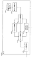
受信IDリスト保持部140は、ECU100aが受信するID(メッセージID)のリストである受信IDリストを保持する。図4に、受信IDリストの一例を示す。
The reception ID
フレーム処理部150は、受信したフレームのデータに応じてECU毎に異なる機能に係る処理を行う。例えば、エンジン101に接続されたECU100aは、時速が30kmを超えた状態でドアが開いている状態だと、アラーム音を鳴らす機能を備える。ECU100aは、例えばアラーム音を鳴らすためのスピーカ等を有している。そして、ECU100aのフレーム処理部150は、他のECUから受信したデータ(例えばドアの状態を示す情報)を管理し、エンジン101から取得された時速に基づいて一定条件下でアラーム音を鳴らす処理等を行う。なお、フレーム処理部150は、ここで例示した以外のフレームのデータに係る処理を行っても良い。
The
データ取得部160は、ECUにつながっている機器、センサ等の状態を示すデータを取得し、フレーム生成部170に通知する。
The
フレーム生成部170は、フレーム解釈部120から通知されたエラーフレームの送信を指示する通知に従い、エラーフレームを構成し、エラーフレームをフレーム送受信部110へ通知して送信させる。また、フレーム生成部170は、データ取得部160より通知されたデータの値に対して、予め定められたメッセージIDをつけてフレーム(データフレーム)を構成し、フレーム送受信部110へ通知する。なお、ECU100a〜100dのそれぞれが送信するフレームの内容については後に図5〜図8を用いて説明する。
The
[1.4 受信IDリスト例]
図4は、ECU100a〜100dのそれぞれにおいて保持される受信IDリストの一例を示す図である。同図に例示する受信IDリストは、ID(メッセージID)の値が「1」、「2」、「3」及び「4」のいずれかであるメッセージIDを含むフレーム(メッセージ)を選択的に受信して処理するために用いられる。例えば、ECU100aの受信IDリスト保持部140に図4の受信IDリストが保持されていると、メッセージIDが「1」、「2」、「3」及び「4」のいずれでもないフレームについては、フレーム解釈部120でのIDフィールド以後のフレームの解釈が中止される。
[1.4 Example of received ID list]
FIG. 4 is a diagram showing an example of a reception ID list held in each of the
[1.5 エンジンECU100aの送信フレーム例]
図5は、エンジン101に接続されたECU100aから送信されるフレームにおけるID(メッセージID)及びデータフィールド(データ)の一例を示す図である。ECU100aが送信するフレームのメッセージIDは「1」である。データは、時速(km/時)を表し、最低0(km/時)〜最高180(km/時)までの範囲の値を取り、データ長は1byteである。図5の上行から下行へと、ECU100aから逐次送信される各フレームに対応する各メッセージID及びデータを例示しており、0km/時から1km/時ずつ加速されている様子を表している。
[1.5 Example of transmission frame of
FIG. 5 is a diagram showing an example of an ID (message ID) and a data field (data) in a frame transmitted from the
[1.6 ブレーキECU100bの送信フレーム例]
図6は、ブレーキ102に接続されたECU100bから送信されるフレームにおけるID(メッセージID)及びデータフィールド(データ)の一例を示す図である。ECU100bが送信するフレームのメッセージIDは「2」である。データは、ブレーキのかかり具合を割合(%)で表し、データ長は1byteである。この割合は、ブレーキを全くかけていない状態を0(%)、ブレーキを最大限かけている状態を100(%)としたものである。図6の上行から下行へと、ECU100bから逐次送信される各フレームに対応する各メッセージID及びデータを例示しており、100%から徐々にブレーキを弱めている様子を表している。
[1.6 Example of transmission frame of
FIG. 6 is a diagram showing an example of an ID (message ID) and a data field (data) in a frame transmitted from the
[1.7 ドア開閉センサECU100cの送信フレーム例]
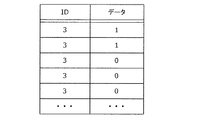
図7は、ドア開閉センサ103に接続されたECU100cから送信されるフレームにおけるID(メッセージID)及びデータフィールド(データ)の一例を示す図である。ECU100cが送信するフレームのメッセージIDは「3」である。データは、ドアの開閉状態を表し、データ長は1byteである。データの値は、ドアが開いている状態が「1」、ドアが閉まっている状態が「0」である。図7の上行から下行へと、ECU100cから逐次送信される各フレームに対応する各メッセージID及びデータを例示しており、ドアが開いている状態から次第に閉められた状態へと移った様子を表している。
[1.7 Example of transmission frame of door open / close sensor ECU100c]
FIG. 7 is a diagram showing an example of an ID (message ID) and a data field (data) in a frame transmitted from the
[1.8 ウィンドウ開閉センサECU100dの送信フレーム例]
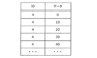
図8は、ウィンドウ開閉センサ104に接続されたECU100dから送信されるフレームにおけるID(メッセージID)及びデータフィールド(データ)の一例を示す図である。ECU100dが送信するフレームのメッセージIDは「4」である。データは、窓(ウィンドウ)の開閉状態を割合(%)で表し、データ長は1byteである。この割合は、窓が完全に閉まっている状態を0(%)、窓が全開の状態を100(%)としたものである。図8の上行から下行へと、ECU100dから逐次送信される各フレームに対応する各メッセージID及びデータを例示しており、窓が閉まっている状態から徐々に開いていく様子を表している。
[1.8 Example of transmission frame of window open / close sensor ECU100d]
FIG. 8 is a diagram showing an example of an ID (message ID) and a data field (data) in a frame transmitted from the
[1.9 ゲートウェイ300の構成]
図9は、ゲートウェイ300の構成図である。ゲートウェイ300は、フレーム送受信部310と、フレーム解釈部320と、受信ID判断部330と、受信IDリスト保持部340と、加工処理部350と、外部通信部360と、車両識別情報保持部361と、異常検知処理部370と、モデル保持部371と、転送処理部380と、転送ルール保持部381と、フレーム生成部390とを含んで構成される。これらの各構成要素の各機能は、例えばゲートウェイ300における通信回路、メモリに格納された制御プログラムを実行するプロセッサ或いはデジタル回路等により実現される。
[1.9
FIG. 9 is a configuration diagram of the
フレーム送受信部310は、バス200a、200bそれぞれに対して、CANプロトコルに従ったフレームを送受信する。フレーム送受信部310は、バスからフレームを1bitずつ受信する受信部として機能し、受信したフレームをフレーム解釈部320に転送する。また、フレーム生成部390より通知を受けた転送先のバスを示すバス情報及びフレームに基づいて、そのフレームの内容をバス200a、200bに1bitずつ送信する。
The frame transmission /
フレーム解釈部320は、フレーム送受信部310よりフレームの値を受け取り、CANプロトコルで規定されているフレームフォーマットにおける各フィールドにマッピングするよう解釈を行う。IDフィールドと判断した値は受信ID判断部330へ転送する。フレーム解釈部320は、受信ID判断部330から通知される判定結果に応じて、IDフィールドの値と、IDフィールド以降に現れるデータフィールド(データ)とを、転送処理部380へ転送するか、その判定結果を受けた以降においてフレームの受信を中止するかを決定する。また、フレーム解釈部320は、IDフィールドの値を、加工処理部350に通知する。また、フレーム解釈部320は、CANプロトコルに則っていないフレームと判断した場合は、エラーフレームを送信するようにフレーム生成部390へ通知する。また、フレーム解釈部320は、エラーフレームを受信した場合、つまり受け取ったフレームにおける値からエラーフレームになっていると解釈した場合には、それ以降はそのフレームを破棄する、つまりフレームの解釈を中止する。
The
受信ID判断部330は、フレーム解釈部320から通知されるIDフィールドの値を受け取り、受信IDリスト保持部340が保持しているメッセージIDのリストに従い、そのIDフィールド以降のフレームの各フィールドを受信するかどうかの判定を行う。この判定結果を、受信ID判断部330は、フレーム解釈部320へ通知する。
The reception
受信IDリスト保持部340は、ゲートウェイ300が受信するID(メッセージID)のリストである受信IDリスト(図4参照)を保持する。
The reception ID
加工処理部350は、サーバ400から通知された検出窓サイズを示す情報に基づいて検出窓サイズを決定してその検出窓サイズを保持する。つまり加工処理部350は、検出窓サイズを決定する決定部として機能する。加工処理部350は、フレーム解釈部320から通知されるIDフィールドの値に基づいて、検出窓サイズの時間長の検出窓毎に、バス200a、200bから逐次受信されたフレームの集合(逐次通知されたIDフィールドの値の集合)を、検出窓におけるID(メッセージID)別のフレームの受信数(検出窓サイズの検出窓内でフレームの受信をID別にカウントして得られたカウント数)を示す特徴情報に変換して特徴情報を外部通信部360へ通知する。つまり加工処理部350は、特徴情報を特定する特定部としても機能する。また、加工処理部350は、バス200a、200bから検出窓サイズの検出窓内に逐次受信されたフレームの数に基づくその特徴情報を異常検知処理部370へ逐次通知する。
The
外部通信部360は、車両識別情報保持部361が保持する車両識別情報を、ネットワーク40を介してサーバ400へ通知(送信)し、応答としてサーバ400から通知された検出窓サイズを示す情報を加工処理部350へ通知する。また、外部通信部360は、加工処理部350から通知された特徴情報をサーバ400に通知(送信)する。また、外部通信部360は、サーバ400から通知されたモデル情報(データフレームの出現頻度に係る基準を表す基準モデルを示す情報)を異常検知処理部370へと通知する。また、外部通信部360は、異常検知処理部370から通知された異常検知結果をサーバ400へ通知(送信)する。
The
車両識別情報保持部361は、車両の識別のための車両識別情報を保持する。図10に、車両識別情報の一例を示す。
The vehicle identification
異常検知処理部370は、サーバ400から通知されたモデル情報を、外部通信部360を介して取得し、モデル情報に従ってモデル保持部371が保持している所定モデル(データフレームの出現頻度に係る基準を表すモデル)を更新する。例えば、異常検知処理部370は、モデル情報が示す基準モデルと一致させるように所定モデルを更新し得る。また、異常検知処理部370は、フレーム解釈部320から通知されるIDフィールドの値に基づいて加工処理部350で変換された特徴情報を受け取り、モデル保持部371が保持している所定モデルと、その特徴情報とを用いた演算処理を行い、その演算処理の結果に応じて異常か否かを判定する判定部として機能する。即ち、異常検知処理部370は、バスから受信されたフレームの集合に係る特徴情報が、所定モデルが表す基準に適合しているか否かを、特徴情報及び所定モデルを用いた演算処理により判定する。この判定では、特徴情報に反映された検出窓サイズでのID別のデータフレームの受信数が、所定モデルが表す基準(例えば正常状態におけるデータフレームの出現頻度を示す基準)に適合していると正常であり、基準に適合していない(つまり基準を逸脱している)と異常であると判定される。このように判定するために演算処理は定められており、演算処理は、例えば所定モデルと特徴情報との比較、算術演算、論理演算、条件判断等といった各種処理の1つ以上の組み合わせである。異常検知処理部370は、その演算処理による異常か否かの判定結果(つまり異常検知結果)を、外部通信部360へ通知する。
The abnormality
モデル保持部371は、異常検知処理部370から通知された所定モデルを保持する。
The
転送処理部380は、転送ルール保持部381が保持する転送ルールに従って、受信したフレームのID(メッセージID)に応じて、転送するバス(転送先のバス)を決定し、転送するバスを示すバス情報とフレーム解釈部320より通知されたメッセージIDとデータとをフレーム生成部390へ通知する。
The
転送ルール保持部381は、バス毎のフレームの転送についてのルールを表す情報である転送ルールを保持する。図11に、転送ルールの一例を示す。
The forwarding
フレーム生成部390は、フレーム解釈部320から通知されたエラーフレームの送信を指示する通知に従い、エラーフレームを構成し、エラーフレームをフレーム送受信部310へ通知して送信させる。また、フレーム生成部390は、転送処理部380より通知されたメッセージIDとデータとを使ってフレームを構成し、そのフレーム及びバス情報をフレーム送受信部310へ通知する。
The
[1.10 車両識別情報]
図10は、ゲートウェイ300が保持する車両識別情報の一例を示す。車両識別情報は、車両の識別のための情報であり、図10では、車両識別情報が、カーメーカ(車両の製造事業者)、車種、及び、車台番号を示す例を示している。この例では、例えば、車台番号は、個々の車両を他の車両と区別する情報(各車両を識別する情報)であり、型式(車両形式)と製造番号とから構成される。ここで、車種が同一の車両同士は、車載ネットワークの構成が同一であり、車載ネットワークのCANバスに流れるデータフレーム(メッセージ)の利用に関する仕様(メッセージID毎のデータフィールドの内容の規定等)は同じである。即ち、ここでの車種が同一の車両は、例えば、車両型式が同一の車両である。なお、車両識別情報は、この例に限られず、例えば、車両識別番号(VIN:Vehicle Identification Number)等であっても良い。例えば、車両識別番号における先頭からシリアル番号の前までの桁の値が同一の車両は、同一車種の車両である。なお、車両識別情報は、必ずしも、それだけで個々の車両が識別可能となる情報である必要はない。例えば、車両識別情報は、車両の車種のみを示す情報であっても良く、車両の製造事業者のみを示す情報であっても良く、車台番号のみを示す情報であっても良く、或いはこれらのいずれかと他の情報とを組み合わせた情報等であっても良い。
[1.10 Vehicle Identification Information]
FIG. 10 shows an example of the vehicle identification information held by the
[1.11 転送ルール]
図11は、ゲートウェイ300の転送ルール保持部381が保持する転送ルールの一例を示す。
[1.11 Forwarding rule]
FIG. 11 shows an example of a forwarding rule held by the forwarding
この転送ルールは、転送元のバスと転送先のバスと転送対象のID(メッセージID)とを対応付けている。図11中の「*」はメッセージIDにかかわらずフレームの転送がなされることを表している。図11の例は、バス200aから受信されるフレームはメッセージIDにかかわらず、バス200bに転送するように設定されていることを示している。また、バス200bから受信されるフレームのうちメッセージIDが「3」であるフレームのみがバス200aに転送されるように設定されていることを示している。
In this transfer rule, the transfer source bus, the transfer destination bus, and the transfer target ID (message ID) are associated with each other. “*” In FIG. 11 indicates that the frame is transferred regardless of the message ID. The example of FIG. 11 shows that the frame received from the
[1.12 サーバ400の構成]
サーバ400は、車両外部に所在し、例えば複数の車両を管理し得るコンピュータであり、メモリ、ハードディスク等の記憶媒体、プロセッサ、通信回路等を含む。
[1.12 Configuration of Server 400]
The
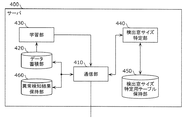
図12は、サーバ400の構成図である。サーバ400は、同図に示すように、通信部410と、データ蓄積部420と、学習部430と、検出窓サイズ特定部440と、検出窓サイズ特定用テーブル保持部450と、異常検知結果保持部460とを含んで構成される。これらの各構成要素は、サーバ400における通信回路、メモリに格納された制御プログラムを実行するプロセッサ等により実現される。
FIG. 12 is a configuration diagram of the
通信部410は、ネットワーク40を介して各車両のゲートウェイ300と通信する。また、通信部410は、ゲートウェイ300から逐次通知される、検出窓サイズ当たりのID別のカウント数を反映した特徴情報を、車両毎に区別して、データ蓄積部420に蓄積する。また、通信部410は、学習部430から通知された基準モデルを示すモデル情報を、ゲートウェイ300へ通知(送信)する。また、通信部410は、ゲートウェイ300から通知された車両識別情報を検出窓サイズ特定部440に通知して、検出窓サイズ特定部440から通知された検出窓サイズを示す情報をゲートウェイ300に通知(送信)する。また、通信部410は、ゲートウェイ300から通知された異常検知結果を異常検知結果保持部460に保持させる。
The
データ蓄積部420は、通信部410から通知された特徴情報を車両毎に区別して蓄積(保持)する。
The
学習部430は、データ蓄積部420に蓄積された車両毎の特徴情報に基づいて、車両毎に対応する基準モデル(車両の車載ネットワークのバスに現れるデータフレームの出現頻度に係る基準を表すモデル)を構築し保持し、特徴情報に基づいて必要に応じて基準モデルを更新する。学習部430は、例えば、通信部410及びデータ蓄積部420によって逐次収集される特徴情報に基づいて、例えば機械学習により、保持している基準モデルを逐次更新する。
The
検出窓サイズ特定部440は、検出窓サイズ特定用テーブル保持部450が保持する検出窓サイズ特定用テーブルを参照して、通信部410から通知された車両識別情報に応じて検出窓サイズを特定し、特定した検出窓サイズを示す情報を通信部410へと通知する。
The detection window
検出窓サイズ特定用テーブル保持部450は、車両識別情報に応じて検出窓サイズを特定するために用いられる検出窓サイズ特定用テーブルを保持する。検出窓サイズ特定用テーブルの一例を図13に示す。
The detection window size specifying
異常検知結果保持部460は、通信部410から通知された異常検知結果を、車両毎にログとして保持する。なお、サーバ400が複数の車両を管理する場合においては、例えば、車両から受信した車両識別情報に基づいて各車両からの情報を類別して管理しても良く、例えば、車両のゲートウェイ300は、特徴情報或いは異常検知結果をサーバ400へ送信する際にも車両識別情報の全部或いは一部を付して送信することとしても良い。
The abnormality detection
[1.13 検出窓サイズ特定用テーブル]
図13は、サーバ400で保持する検出窓サイズ特定用テーブルの一例を示す。図13に示す検出窓サイズ特定用テーブルは、車両識別情報と検出窓サイズとを対応付けたテーブルである。図13に例示する検出窓サイズ特定用テーブルの車両識別情報は、図10の例と同様に、カーメーカ、車種、及び、車台番号を含む。この検出窓サイズは、例えば、車両識別情報により識別される車両の集合における各車両の車載ネットワークシステムでCANバスに正常状態で送信されるべき、複数種類のデータフレーム(つまりメッセージIDが互いに異なる複数のデータフレーム)のうち、送信周期が最短の一種類のデータフレームのその送信周期と一致するように定められ得る。この検出窓サイズを定めるために、車載ネットワークシステムの仕様、或いは、車載ネットワークシステムの正常状態の実情の分析結果等が参照され得る。例えば、車両識別情報が、個々の車両ではなく車種のみを識別するものであれば、その車種の各車両における車載ネットワークシステムで、正常状態で送信される複数のIDのフレームの送信周期のうち最短の周期のものと一致するように、検出窓サイズが定められ得る。検出窓サイズ特定用テーブルにおける検出窓サイズの定め方は、この他の方法によっても良く、結果的に車両の異常検知装置(ゲートウェイ300)において、正常状態と攻撃された状態とを適切に区別できるように、検出窓サイズを定めておくことが有用である。
[1.13 Detection window size specification table]
FIG. 13 shows an example of a detection window size specifying table held by the
[1.14 ECU100aのフレーム送信処理]
図14は、ECU100aにおけるフレーム送信処理シーケンスの一例を示す。以下、同図に即してECU100aによるフレーム送信処理について説明する。
[1.14 Frame transmission process of
FIG. 14 shows an example of a frame transmission processing sequence in the
ECU100aは、データ取得部160により、センサからデータ(例えばエンジン101に関連してセンサで測定された車速)を取得する(ステップS1101)。
The
次にECU100aは、取得したセンサのデータに基づいて、フレーム生成部170により、送信すべきフレーム(データフレーム)を生成する(ステップS1102)。
Next, the
次にECU100aは、生成したフレームをバス200aに対して送信(ブロードキャスト)する(ステップS1103)。このステップS1101からS1103までの処理は、概ね一定の周期で、周期的に繰り返され得る。
Next, the
ECU100b〜100dにおいても、ECU100aと同様な手順でフレーム送信処理が行われ得る。但し、送信の周期は、ECU毎に異なり得る。
Also in the
[1.15 ゲートウェイ300のフレーム転送処理]
図15は、ゲートウェイ300におけるフレーム転送処理シーケンスの一例を示す。以下、同図に即してゲートウェイ300によるフレーム転送処理について説明する。ゲートウェイ300は、バス200a及びバス200bのいずれかからフレーム(データフレーム)を受信する度にこのフレーム転送処理を行う。ここでは、ゲートウェイ300が、バス200aから受信したフレームをバス200bに転送する例を用いて説明する。
[1.15
FIG. 15 shows an example of a frame transfer processing sequence in the
ゲートウェイ300は、バス200aに送信(ブロードキャスト)されたフレームを受信する(ステップS1201)。
The
次に、ゲートウェイ300は、転送ルール(図11参照)を確認する(ステップS1202)。
Next, the
ゲートウェイ300は、転送ルールに基づいて、受信したフレームが転送されるべきフレームであると判定した場合には、そのフレームの内容に基づいて転送用フレームを生成する(ステップS1203)。
When the
次に、ゲートウェイ300は、転送用フレームをバス200bに送信(ブロードキャスト)して、フレーム転送処理を終える(ステップS1204)。なお、ステップS1202で確認した転送ルールに基づいて、受信したフレームが転送されるべきフレームでないと判定した場合には、ゲートウェイ300は、フレームの転送を行わずにフレーム転送処理を終える。
Next, the
[1.16 検出窓サイズ決定処理シーケンス]
図16は、ゲートウェイ300及びサーバ400の連携による検出窓サイズ決定処理シーケンスの一例を示す。以下、同図に即して検出窓サイズ決定処理シーケンスについて説明する。
[1.16 Detection window size determination processing sequence]
FIG. 16 shows an example of the detection window size determination processing sequence in cooperation with the
ゲートウェイ300は、車両識別情報を取得する(ステップS1301)。ゲートウェイ300は、車両識別情報を車両識別情報保持部361から取得する。車両識別情報保持部361には、例えば、ゲートウェイ300が車両に搭載された際(例えば車両の製造の際等)において車両識別情報が保持されていても良いし、予め記録された車両識別情報を保持する車両内のECUからゲートウェイ300がその車両識別情報を受信することで、車両識別情報保持部361に保持させることとしても良い。
The
ゲートウェイ300は、ステップS1301で取得した車両識別情報を、サーバ400に送信する(ステップS1302a)。これにより、サーバ400は、車両識別情報を受信する(ステップS1302b)。なお、ゲートウェイ300が、サーバ400に車両識別情報を送信するタイミングは、例えば、ゲートウェイ300が車両に搭載された際(例えば車両の製造の際等)であるが、この他のタイミングであっても良いし、そのタイミングは複数であっても良い。この他のタイミング(ゲートウェイ300がサーバ400に車両識別情報を送信するタイミング)の例としては、車両の走行開始時等といった車両を使用する際毎(例えば車両のエンジン始動の際、アクセサリ−オン(ACC−ON)の際等)、所定時間(例えば1日)毎等が挙げられる。そして、ゲートウェイ300が、サーバ400に車両識別情報を送信するタイミングの到来に合わせて図16に示す検出窓サイズ決定処理シーケンスの全体が実行され得る。
The
サーバ400では、ステップS1302bで受信した車両識別情報に応じて、検出窓サイズ特定部440により検出窓サイズを特定し(ステップS1303)、特定した検出窓サイズを示す情報(検出窓サイズ情報)を、車両識別情報に対する応答として、ゲートウェイ300に送信する(ステップS1304a)。これにより、ゲートウェイ300は、検出窓サイズ情報を受信する(ステップS1304b)。
In the
ゲートウェイ300は、受信した検出窓サイズ情報に従って、加工処理部350において検出窓サイズを決定して、検出窓サイズを保持する(ステップS1305)。
The
[1.17 学習処理シーケンス]
図17は、ゲートウェイ300及びサーバ400の連携による学習処理シーケンスの一例を示す。学習処理シーケンスでは、車両の車載ネットワークにおいてゲートウェイ300が受信したフレームの集合に加工処理を加えてなる特徴情報をサーバ400に送信し、サーバ400では特徴情報を基準モデルへ反映する。以下、図17に即して学習処理シーケンスについて説明する。
[1.17 Learning processing sequence]
FIG. 17 shows an example of a learning processing sequence in which the
ゲートウェイ300は、加工処理部350において、保持している検出窓サイズの時間長の検出窓毎に、バス200a及びバス200bからフレーム(データフレーム)を受信すると(ステップS1401)、検出窓内におけるID(メッセージID)別のフレームの受信数をカウントする(ステップS1402)。
When the
加工処理部350は、検出窓サイズ分の時間の経過(つまり1つの検出窓の終期の到来)を判定し(ステップS1403)、検出窓の終期が到来したら、ID別のフレームの受信数(カウント数)に基づき加工処理により特徴情報を生成する(ステップS1404)。続いてゲートウェイ300は、加工処理部350で生成した特徴情報をサーバ400に送信し(ステップS1405a)、加工処理部350ではカウント数をクリアして(ステップS1406)、次の検出窓についての処理に戻る(つまりステップS1401での処理へ戻る)。なお、ゲートウェイ300は、ステップS1403で、検出窓の終期が到来していないと判定された場合には、ステップS1401での処理に戻る。
The
ステップS1405aでのゲートウェイ300による特徴情報の送信に呼応して、サーバ400では、特徴情報を受信し(ステップS1405b)、学習部430で、受信した特徴情報を基準モデルに反映する(ステップS1407)。なお、サーバ400は、特徴情報を受信する毎に基準モデルへの反映を行うこととしても良いし、複数の特徴情報を受信してからデータ蓄積部420に蓄積し、複数の特徴情報をまとめて学習部430で特徴情報の基準モデルへの反映を行うこととしても良い。この学習処理シーケンスは、車両の車載ネットワークにおいて正常状態で受信されたフレームに係る特徴情報を基準モデルに反映することで、基準モデルが、その車両の車載ネットワークのバスに現れるフレームの出現頻度に係る基準となることを想定している。基準モデルは、例えば、車両から取得した車両識別情報毎に定められる。基準モデルは、例えば車両毎に定められるが、例えば、同一車種の車両においては共通にすることとしても良い。即ち、サーバ400が車両からの車両識別情報に応じて検出窓サイズを示す情報を送信したその送信先の車両に対応して、基準モデルが存在し、その基準モデルを示すモデル情報が、後述のモデル更新処理シーケンスでその車両に送信される。なお、特徴情報の基準モデルへの反映は、例えば、特徴情報を用いた機械学習により基準モデルを更新することで行われるようにしても良い。
In response to the transmission of the feature information by the
以下、学習処理シーケンスで用いた検出窓サイズの時間長の検出窓と加工処理により生成された特徴情報との一例について、図18を用いて説明する。 Hereinafter, an example of the time-length detection window of the detection window size used in the learning processing sequence and the feature information generated by the processing processing will be described with reference to FIG.
ゲートウェイ300の加工処理部350では、検出窓サイズの時間長の各期間(各検出窓T1、T2、T3)において、検出窓内にバスから受信されたフレームの数に基づく特徴情報を特定する。図18では、特徴情報として、受信されたメッセージID毎のフレームの数を成分とする特徴ベクトルを特徴情報として特定する例を示している。図18では、IDが1であるフレームをID1、IDが2であるフレームをID2等と表現している。特徴ベクトルは、例えば、検出窓内におけるID1の受信数(カウント数)、ID2の受信数、ID3の受信数、ID4の受信数のそれぞれを成分とするベクトルである。ベクトルの成分数は、例えば、バスに出現する全てのメッセージIDの数である。図18の例では、ID1、ID2、ID3、ID4の各受信数をこの順に並べた成分を有する特徴ベクトルを示している。検出窓T1においてID1、ID2、ID3の受信数は1でありID4の受信数は0であるので、検出窓T1における特徴ベクトルは[1,1,1,0,・・・]となっている。また、検出窓T2においてID1、ID2、ID4の受信数は1でありID3の受信数は0であるので、検出窓T2における特徴ベクトルは[1,1,0,1,・・・]となっている。また、検出窓T3においてID1、ID3の受信数は1でありID2、ID4の受信数は0であるので、検出窓T3における特徴ベクトルは[1,0,1,0,・・・]となっている。なお、ゲートウェイ300で検出窓サイズの期間においてカウントしたID毎の受信したフレームの数を、サーバ400の基準モデルへ反映するまでにおける、ゲートウェイ300とサーバ400との処理(加工処理等)の分担は、いかなるものでも良い。また、加工処理において、主成分分析等を用いることで、特徴情報としての特徴ベクトルの次元数(成分の数)を削減しても良い。
The
サーバ400では、特徴情報を基準モデルに反映する際に、例えば、その基準モデルと同様の所定モデルを用いたゲートウェイ300での異常の検知を効率的に行えるようにするための加工等を施しても良い。一例としては、サーバ400は、ゲートウェイ300から逐次取得した特徴情報としての、上述の次元数を削減等した特徴ベクトルの集合を、kd木(k-dimensional tree)等の最近傍距離の計算に適したデータ構造にすることをもって基準モデルへの反映を行う。
When the feature information is reflected in the reference model, the
[1.18 モデル更新処理シーケンス]
図19は、ゲートウェイ300及びサーバ400の連携によるモデル更新処理シーケンスの一例を示す。モデル更新処理シーケンスでは、サーバ400において更新された基準モデルを、車両のゲートウェイ300が保持する所定モデルに反映する。以下、図19に即してモデル更新処理シーケンスについて説明する。モデル更新処理シーケンスは、任意のタイミング(例えば1日毎)に実行される。
[1.18 Model update processing sequence]
FIG. 19 shows an example of a model update processing sequence in which the
サーバ400は、上述の学習処理シーケンスの結果として基準モデルの更新(基準モデルの内容の変化)があったか否かを判定する(ステップS1501)。基準モデルの更新があった場合には、サーバ400は、更新後の基準モデルを示すモデル情報を、ゲートウェイ300に送信する(ステップS1502a)。これに呼応してゲートウェイ300は、基準モデルを示すモデル情報を受信する(ステップS1502b)。
The
ゲートウェイ300は、モデル情報を受信すると、異常検知処理部370で、モデル情報に従ってモデル保持部371が保持している所定モデルを更新する(ステップS1503)。これにより、所定モデルは、例えばサーバ400における基準モデルと同様となる。
When the
[1.19 異常検知処理シーケンス]
図20は、ゲートウェイ300及びサーバ400の連携による異常検知処理シーケンスの一例を示す。異常検知処理シーケンスは、例えば車両が使用される段階において実行される。ゲートウェイ300が車両の車載ネットワークのバス200a、200bを流れるフレームを監視して、所定モデルを用いて異常状態が生じているか否かを判定することで異常を検知する処理を含む。所定モデルは、上述のモデル更新処理シーケンスにより、上述の学習処理シーケンスで更新された基準モデルと同様となるように構成されている。なお、上述の学習処理シーケンスは、この異常検知処理シーケンスより前(例えば、車両の使用前、つまり製造或いは検査段階等)に行われ得るが、車両が使用される段階で異常検知処理シーケンスと並行して行われても良い。以下、図20に即して異常検知処理シーケンスについて説明する。
[1.19 Anomaly detection processing sequence]
FIG. 20 shows an example of an abnormality detection processing sequence in which the
ゲートウェイ300では、フレームが受信されると(ステップS1601)、加工処理部350で、検出窓サイズの検出窓内におけるID別のフレームの受信数をカウントし(ステップS1602)、加工処理によって例えば特徴ベクトルである特徴情報を生成する(ステップS1603)。1つの検出窓においてステップS1601〜ステップS1602での処理が繰り返し行われ、検出窓の終期においてステップS1603での特徴情報の生成が行われてID別のフレームの受信数をカウントするカウンタがクリアされる。
In the
次にゲートウェイ300は、異常検知処理部370により、加工処理部350で生成された特徴情報を受け取り、その特徴情報が、モデル保持部371が保持している所定モデルが示す基準に適合しているか、その基準を逸脱しているかを判定する(ステップS1604)。即ち、異常検知処理部370は、特徴情報と所定モデルとを用いた演算処理を行い、その演算処理の結果に応じて、特徴情報が、所定モデルが表す基準を逸脱しているか否か(つまり異常か否か)を判定する。演算処理の一例としては、加工処理部350から受け取った特徴情報としての特徴ベクトル(図18参照)の、kd木等のデータ構造で表された所定モデルが示す基準(例えば正常状態での特徴ベクトルの分布)に対する最近傍距離を計算して、閾値と比較する処理が、挙げられる。例えば、最近傍距離が正規分布に従うとして、閾値で定めた、平均から標準偏差の一定倍(例えば3倍)の範囲内を逸脱した場合に、異常と判定される。
Next, the
ゲートウェイ300は、ステップS1604で特徴情報が、所定モデルが示す基準を逸脱していない(基準に適合している)と判定した場合には、正常と判定して(ステップS1605)、特にサーバ400への送信を行わない。一方、特徴情報が、所定モデルが示す基準を逸脱していると判定した場合には、異常と判定して(ステップS1606)、異常検知結果をサーバ400に送信する(ステップS1607a)。
When the
サーバ400は、異常検知結果を受信すると(ステップS1607b)、異常検知結果をログとして保存する(ステップS1608)。
When the
[1.20 実施の形態1の効果]
実施の形態1に係る異常検知システム10では、車両に搭載された異常検知装置としてのゲートウェイ300が、その車両の識別のための車両識別情報をサーバ400に送信し、サーバ400からの応答に基づいて検出窓サイズ(異常検知のためにフレームの受信数をカウントするための単位時間)を決定する。これにより、車両毎に適切な検出窓サイズを用いて車載ネットワークの異常の検知を精度良く行うことが可能となり得る。また、異常検知システム10では、異常の判定(検知)に用いるモデル(所定モデル或いは基準モデル)の学習のために、ゲートウェイ300側で受信したフレームに係る特徴ベクトルを生成する加工処理を行うことで、サーバ400との間の通信量の削減が可能となる。また、加工処理では、主成分分析等による特徴ベクトルの次元の削減等も行い得るので、これにより更に通信量を削減することが可能となり、また、結果的にモデルに基づく異常の判定のための演算量を削減することが可能となり得る。また、サーバ400が、データ(車両から受信した特徴情報)の蓄積、特徴情報を反映したモデルの構築(基準モデルの更新等)を行うことで、車載のゲートウェイ300の限られたリソースにより制限を受けることなく、最適なモデルを構築し得る。また、サーバ400で構築(更新)した基準モデルをゲートウェイ300が取得して、異常の判定(検知)のために用いることで、車両において迅速に異常か否かの判定(つまり異常の検知)を行うことが可能となり得る。そして、ゲートウェイ300は、異常検知結果をサーバ400に通知するので、サーバ400では異常検知結果をログとして保存し、車両を管理することができ、また、その異常検知結果に基づいて、より適切な基準モデルを構築する等が可能となり得る。また、例えば、車両識別情報で車種を示すようにした場合においては、サーバ400は、同一車種の複数の車両から特徴情報を収集することでその車種に対応する基準モデルを、その車種で攻撃された状況と正常状態を区別可能に適切に構築することが可能となる。そして、サーバ400が、その同一車種の車両のゲートウェイ300に対して、基準モデルを示すモデル情報を送信することで、同一車種の各車両は、基準モデルと同様の所定モデルに基づいて適切に異常を検知し得る。なお、異常の検知により、異常に対する各種対処(警告の報知、安全のための走行制御その他の処理)が可能となり得る。
[Effect of 1.20 Embodiment 1]
In the
(実施の形態2)
以下、実施の形態1で示した異常検知システムにおける車両の車載ネットワークシステムを変形した実施態様について説明する。
(Embodiment 2)
Hereinafter, an embodiment in which the vehicle-mounted network system of the vehicle in the abnormality detection system shown in the first embodiment is modified will be described.
実施の形態1では、車両のゲートウェイ300が、車両外部のサーバ400と通信することで検出窓サイズを決定し、車載ネットワークの異常の検知のために用いる所定モデルの基礎となる基準モデルを学習により更新するために、検出窓サイズ分の時間におけるID別のフレームの受信数に基づく特徴情報をサーバ400に送信した。これに対して、本実施の形態では、車両の車載ネットワークシステムにおける異常検知装置が独立して(つまり車両外部のサーバに依存せずに)、異常の検知に用いる検出窓サイズを決定する例について説明する。
In the first embodiment, the
[2.1 車載ネットワークシステムの構成]
図21は、本実施の形態に係る車両の車載ネットワークシステムの構成を示す。なお、実施の形態1(図1参照)と同様の構成については、図21において図1と同一の符号を付しており、説明を省略する。
[2.1 In-vehicle network system configuration]
FIG. 21 shows the configuration of the vehicle-mounted network system of the vehicle according to the present embodiment. The same configurations as those in the first embodiment (see FIG. 1) are designated by the same reference numerals as those in FIG. 21 in FIG. 21, and the description thereof will be omitted.
図21に示す車両における車載ネットワークシステムは、ECU100a、ECU100b、ECU100c及びECU100dと、バス200a、200bと、ゲートウェイ1300(異常検知装置の一例)とを含んで構成される。各ECUは、CANプロトコルに従って車両内のバス200a、200bを介してフレームの授受を行い得る。
The vehicle-mounted network system shown in FIG. 21 includes an
ゲートウェイ1300は、実施の形態1で示したゲートウェイ300を部分的に変形した異常検知装置であり、ここで特に示さない点についてはゲートウェイ300と同様である。
The
ゲートウェイ1300は、バス200a及びバス200bと接続され、一方のバスから受信したフレームを他方のバスに転送する機能を有し、バスから受信したフレームに基づいて異常か否かを判定すること(例えば攻撃フレームがバスに流れている異常状態であるか否かを判定すること)で異常を検知する機能を有する。また、ゲートウェイ1300は、異常検知(異常か否かの判定)等に用いるための検出窓サイズを決定する機能、検出窓サイズの時間長の期間である検出窓内に、車載ネットワークで受信されたフレームの数に係る特徴情報に基づいて、異常検知に用いるための所定モデルを更新する機能を有する。
The
[2.2 ゲートウェイ1300の構成]
図22は、ゲートウェイ1300の構成図である。ゲートウェイ1300は、フレーム送受信部310と、フレーム解釈部320と、受信ID判断部330と、受信IDリスト保持部340と、加工処理部1350と、車両識別情報保持部361と、異常検知処理部1370と、モデル保持部1371と、転送処理部380と、転送ルール保持部381と、フレーム生成部390と、検出窓サイズ決定部1440と、検出窓サイズ特定用テーブル保持部450と、学習部1430と、異常検知結果保持部1460とを含んで構成される。これらの各構成要素の各機能は、例えばゲートウェイ1300における通信回路、メモリに格納された制御プログラムを実行するプロセッサ或いはデジタル回路等により実現される。なお、図9に示したゲートウェイ300と同様の構成、或いは、図12に示したサーバ400と同様の構成については、図22において同一の符号を付しており、説明を省略する。
[2.2 Configuration of gateway 1300]
FIG. 22 is a configuration diagram of the
検出窓サイズ決定部1440は、検出窓サイズを決定する決定部として機能する。検出窓サイズ決定部1440は、車両識別情報保持部361が保持する車両識別情報に応じて、検出窓サイズ特定用テーブル保持部450が保持する検出窓サイズ特定用テーブル(図13参照)を用いて検出窓サイズを決定し、加工処理部1350へと通知する。
The detection window
加工処理部1350は、実施の形態1で示した加工処理部350の一部を変形したものであり、検出窓サイズ決定部1440から通知された検出窓サイズを保持し、フレーム解釈部320から通知されるIDフィールドの値に基づいて、検出窓サイズの時間長の検出窓毎に、バス200a、200bから逐次受信されたフレームの集合(逐次通知されたIDフィールドの値の集合)を、検出窓におけるID(メッセージID)別のフレームの受信数(検出窓サイズの検出窓内でフレームの受信をID別にカウントして得られたカウント数)を示す特徴情報に変換して特徴情報を定期的に学習部1430へ通知する。つまり加工処理部1350は、特徴情報を特定する特定部として機能する。また、加工処理部1350は、バス200a、200bから検出窓サイズの検出窓内に逐次受信されたフレームの数に基づくその特徴情報を異常検知処理部1370へ逐次通知する。
The
モデル保持部1371は、所定モデル(車両の車載ネットワークのバスに現れるデータフレームの出現頻度に係る基準を表すモデル)を保持する。
The
学習部1430は、加工処理部1350から通知された特徴情報に基づいて、所定モデルを構築して、モデル保持部1371に保持させる。即ち、学習部1430は、モデル保持部1371が保持する所定モデルを、特徴情報に基づいて更新する。学習部1430による所定モデルの更新は、実施の形態1で示した学習部430による基準モデルの更新と同様の方法で行われ得る。学習部1430は、例えば、逐次通知される特徴情報に基づいて、例えば機械学習により、所定モデルを逐次更新し得る。
The
異常検知処理部1370は、フレーム解釈部320から通知されるIDフィールドの値に基づいて加工処理部1350で生成された特徴情報を受け取り、モデル保持部1371が保持している所定モデルと、その特徴情報とを用いた演算処理を行い、その演算処理の結果に応じて異常か否かを判定する。即ち、異常検知処理部1370は、バスから受信されたフレームの集合に係る特徴情報が、所定モデルが表す基準に適合しているか否かを、特徴情報及び所定モデルを用いた演算処理により判定する判定部として機能する。この判定では、特徴情報に反映された検出窓サイズでのID別のデータフレームの受信数が、所定モデルが表す基準(例えば正常状態におけるデータフレームの出現頻度を示す基準)に適合していると正常であり、基準に適合していない(つまり基準を逸脱している)と異常であると判定される。また、異常検知処理部370は、その演算処理による異常か否かの判定結果(つまり異常検知結果)を、異常検知結果保持部1460にログとして保存する。
The abnormality
[2.3 検出窓サイズ決定処理シーケンス]
図23は、ゲートウェイ1300における検出窓サイズ決定処理シーケンスの一例を示す。以下、同図に即して検出窓サイズ決定処理シーケンスについて説明する。この検出窓サイズ決定処理シーケンスが実行されるタイミングは、例えば、ゲートウェイ1300が車両に搭載された際(例えば車両の製造の際等)であるが、この他のタイミングであっても良いし、そのタイミングは複数であっても良い。この他のタイミングの例としては、車両を使用する際毎(例えば車両のエンジン始動の際、アクセサリ−オン(ACC−ON)の際等)、所定時間(例えば1日)毎等が挙げられる。なお、図16と同様のステップについては、図23において同一の符号を付しており、説明を適宜省略する。
[2.3 Detection window size determination processing sequence]
FIG. 23 shows an example of the detection window size determination processing sequence in the
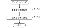
ゲートウェイ1300は、車両識別情報を取得する(ステップS1301)。
The
次にゲートウェイ1300は、ステップS1301で取得した車両識別情報に応じて、検出窓サイズ特定用テーブル(図13参照)を用いて検出窓サイズを決定する(ステップS2303)。ゲートウェイ1300は、決定した検出窓サイズを保持し、加工処理部1350で加工処理を実行する際に検出窓サイズを用いる。なお、ゲートウェイ1300は、車両外部との通信機能を有していても良く、その場合に、検出窓サイズ特定用テーブルを通信により、車両外部から取得することとしても良いし、記録媒体等から検出窓サイズ特定用テーブルを読み出すことで取得することとしても良い。
Next, the
[2.4 学習処理シーケンス]
図24は、ゲートウェイ1300における学習処理シーケンスの一例を示す。学習処理シーケンスでは、ゲートウェイ1300が、バス200a、200bから受信したフレームの集合に加工処理を加えてなる特徴情報に基づく学習により、モデル保持部1371が保持する所定モデルを更新する。以下、図24に即して学習処理シーケンスについて説明する。なお、図17と同様のステップについては、図24において同一の符号を付しており、説明を適宜省略する。
[2.4 Learning processing sequence]
FIG. 24 shows an example of the learning processing sequence in the
ゲートウェイ1300は、検出窓サイズの時間長の検出窓毎に、バス200a及びバス200bからフレームを受信すると(ステップS1401)、検出窓内におけるID別のフレームの受信数をカウントする(ステップS1402)。
When the
加工処理部1350は、検出窓サイズ分の時間が経過(検出窓の終期が到来)したら、ID別のフレームの受信数(カウント数)に基づき加工処理により特徴情報を生成する(ステップS1404)。
When the time corresponding to the size of the detection window has elapsed (the end of the detection window has arrived), the
ゲートウェイ1300は、加工処理部1350で生成した特徴情報を、学習部1430で、モデル保持部1371が保持する所定モデルに反映する(ステップS2407)。この学習処理シーケンスは、車載ネットワークにおいて正常状態で受信されたフレームに係る特徴情報を所定モデルに反映することで、所定モデルが、この車載ネットワークのバスに現れるフレームの出現頻度に係る基準となることを想定している。特徴情報の所定モデルへの反映は、例えば、特徴情報を用いた機械学習により所定モデルを更新することで行われるようにしても良い。なお、加工処理部1350は、実施の形態1で示した加工処理部350と同様に、検出窓において受信されたメッセージID毎のフレームの数を成分とする特徴ベクトルを特徴情報としても良く、加工処理において、主成分分析等を用いることで、特徴ベクトルの次元数を削減しても良い。また、学習部1430は、特徴情報を所定モデルに反映する際に、例えば、その所定モデルを用いた異常の検知を効率的に行えるようにするための加工等を施しても良い。一例としては、学習部1430は、特徴ベクトルの集合を、kd木等の最近傍距離の計算に適したデータ構造にすることをもって所定モデルへの反映を行う。
The
ステップS2407での処理に続いて、ゲートウェイ1300は、カウント数をクリアして(ステップS1406)、ステップS1401での処理に戻る。
Following the processing in step S2407, the
[2.5 異常検知処理シーケンス]
図25は、ゲートウェイ1300における異常検知処理シーケンスの一例を示す。異常検知処理シーケンスは、例えば車両が使用される段階において実行される。異常検知処理シーケンスでは、ゲートウェイ1300が、車両の車載ネットワークのバス200a、200bを流れるフレームを監視して、所定モデルを用いて異常状態が生じているか否かを判定することで異常を検知する。なお、上述の学習処理シーケンスは、この異常検知処理シーケンスより前(例えば、車両の使用前、つまり製造或いは検査段階等)に行われ得るが、車両が使用される段階で異常検知処理シーケンスと並行して行われても良い。以下、図25に即して異常検知処理シーケンスについて説明する。なお、図20と同様のステップについては、図25において同一の符号を付しており、説明を適宜省略する。
[2.5 Anomaly detection processing sequence]
FIG. 25 shows an example of the abnormality detection processing sequence in the
ゲートウェイ1300では、フレームが受信されると(ステップS1601)、加工処理部1350で、検出窓サイズの検出窓内におけるID別のフレームの受信数をカウントし(ステップS1602)、加工処理によって例えば特徴ベクトルである特徴情報を生成する(ステップS1603)。1つの検出窓においてステップS1601〜ステップS1602での処理が繰り返し行われ、検出窓の終期においてステップS1603での特徴情報の生成が行われてID別のフレームの受信数をカウントするカウンタがクリアされる。
In the
次にゲートウェイ1300は、異常検知処理部1370により、加工処理部1350で生成された特徴情報を受け取り、その特徴情報が、モデル保持部1371が保持している所定モデルが示す基準に適合しているか、その基準を逸脱しているかを判定する(ステップS1604)。
Next, the
ゲートウェイ1300は、ステップS1604で、特徴情報が、所定モデルが示す基準を逸脱していない(基準に適合している)と判定した場合には、正常と判定し(ステップS1605)、一方、特徴情報が、所定モデルが示す基準を逸脱していると判定した場合には、異常と判定して(ステップS1606)、その判定結果をログとして保存する(ステップS2608)。なお、ゲートウェイ1300は、この判定結果を用いて機械学習(例えば教師有り学習)等により所定モデルを更新しても良い。
If the
[2.6 実施の形態2の効果]
実施の形態2に係る異常検知装置(ゲートウェイ1300)は、サーバ等と通信しなくても、自ら自装置が搭載されている車両の識別のための車両識別情報を取得してその車両識別情報に応じて検出窓サイズ(異常検知のためにフレームの受信数をカウントするための単位時間)を決定し得る。これにより、ゲートウェイ1300は、自装置を搭載した車両に適切な検出窓サイズを用いて車載ネットワークの異常の検知を精度良く行うことが可能となり得る。また、ゲートウェイ1300は、車載ネットワークの監視に基づいて生成した特徴情報を反映した所定モデルの構築(所定モデルの更新等)を行い、所定モデルを用いて異常の判定(検知)を行うので、車両において迅速に異常か否かの判定(つまり異常の検知)を行うことが可能となり得る。また、ゲートウェイ1300は、異常か否かの判定結果をログとして保存でき、その判定結果を活用し得る。
[Effect of 2.6 Embodiment 2]
The abnormality detection device (gateway 1300) according to the second embodiment acquires the vehicle identification information for identifying the vehicle on which the own device is mounted and uses the vehicle identification information as the vehicle identification information without communicating with the server or the like. The detection window size (unit time for counting the number of frames received for abnormality detection) can be determined accordingly. As a result, the
(その他変形例)
以上のように、本発明に係る技術の例示として実施の形態1、2を説明した。しかしながら、本発明に係る技術は、これに限定されず、適宜、変更、置き換え、付加、省略等を行った実施の形態にも適用可能である。例えば、以下のような変形例も本発明の一実施態様に含まれる。
(Other variants)
As described above,
(1)上記実施の形態では、決定された検出窓サイズの時間長の検出窓が重複なく連続する例を示したが(図18参照)、検出窓サイズ分の期間である各検出窓は、重複なく連続するものに限られない。図26に示すように、ゲートウェイ(異常検知装置)が、検出窓T1と一部重複する検出窓TA内においてもバスから受信されるフレームの数をID別にカウントすることで、ID別の受信数(カウント数)を成分とする特徴ベクトルを生成して特徴情報としても良い。この場合において、例えば、ゲートウェイは、検出窓TAの開始時点と基準となる開始時点(例えば先行する検出窓T1の開始時点)との差であるオフセット時間を示す情報を特徴情報に含ませてサーバに送信することとしても良い。また、例えば、検出窓サイズ(例えば10ms)分の各検出窓の開始時点を一定時間(例えば1ms)毎等と定めることとしても良い。また、バスから特定のIDのフレームを受信したタイミング等を検出窓の開始時点とすることとしても良い。 (1) In the above embodiment, an example is shown in which the detection windows having a determined detection window size and the time length are continuous without duplication (see FIG. 18), but each detection window having a period corresponding to the detection window size is It is not limited to continuous ones without duplication. As shown in FIG. 26, the gateway (abnormality detection device) counts the number of frames received from the bus by ID even in the detection window TA that partially overlaps with the detection window T1, so that the number of frames received by ID is counted. A feature vector having (count number) as a component may be generated and used as feature information. In this case, for example, the gateway includes information indicating an offset time, which is the difference between the start time point of the detection window TA and the reference start time point (for example, the start time point of the preceding detection window T1), in the feature information. It may be sent to. Further, for example, the start time point of each detection window corresponding to the detection window size (for example, 10 ms) may be set to every fixed time (for example, 1 ms). Further, the timing at which the frame of a specific ID is received from the bus may be set as the start time of the detection window.
(2)上記の実施の形態では、データフレーム(メッセージ)の転送機能を有するゲートウェイ300、1300を、異常を検知する異常検知装置の一例として示したが、異常検知装置は、1つ以上のバスに接続された装置であれば良く、必ずしも転送機能を有する必要はない。異常検知装置は、異常を検知する機能以外の機能を併せ持つECUであっても良い。また、例えば、異常検知装置は、ゲートウェイ300、1300における1つ以上の構成要素を省略し得るし、その1つ以上の構成要素を他のECUに移動させても良い。
(2) In the above embodiment, the
(3)上記実施の形態では、CANプロトコルにおけるデータフレーム(メッセージ)を標準IDフォーマット(図2参照)で記述しているが、拡張IDフォーマットであっても良く、メッセージIDは、拡張IDフォーマットでの拡張ID等であっても良い。また、上記実施の形態で示したCANプロトコルは、TTCAN(Time-Triggered CAN)、CANFD(CAN with Flexible Data Rate)等の派生的なプロトコルも包含する広義の意味のものとしても良い。 (3) In the above embodiment, the data frame (message) in the CAN protocol is described in the standard ID format (see FIG. 2), but it may be in the extended ID format, and the message ID is in the extended ID format. It may be an extended ID of. Further, the CAN protocol shown in the above embodiment may have a broad meaning including derivative protocols such as TTCAN (Time-Triggered CAN) and CANFD (CAN with Flexible Data Rate).
(4)上記実施の形態1では、ゲートウェイ300が外部通信部360を有する例を示したが、車載ネットワークに接続されたヘッドユニット或いは他のECU(車外と通信する機能を有する装置)を経由して通信するとしても良い。ヘッドユニットは、例えば、マルチメディア再生、カーナビゲーション等の機能のために、車両外部との通信機能を有しているECUである。また、車載ネットワークにおいて、OBD2(On-Board Diagnostics2)等の診断ポートに接続される診断ツール(故障診断ツール)等が、サーバ400との通信機能を有する場合において、ゲートウェイ300は、その診断ツールを経由してサーバ400と通信することとしても良い。
(4) In the first embodiment, the
(5)上記実施の形態では、ゲートウェイ300、1300は、検出窓サイズの期間でのID別のフレームの受信数に基づく特徴情報が、所定モデルが示す基準から逸脱する場合に異常と判定しているが、例えば所定モデルの示す内容を逆にすることで、所定モデルに適合する場合(逸脱しない場合)を異常と判定し、逸脱する場合を正常と判定しても良い。また、実施の形態1では、異常検知結果が異常である場合のみ、ゲートウェイ300がサーバ400へ異常検知結果を送信してサーバ400で異常検知結果を保存することとしたが、正常な場合にも異常検知結果を保存するとしても良い。
(5) In the above embodiment, the
(6)上記実施の形態では、ゲートウェイ300、1300が検出窓サイズ分の期間である検出窓内にバスから受信したデータフレームの数をID別にカウントすることでその受信数(カウント数)に基づいて特徴情報を生成する例を示した。しかし、特徴情報は、ID別にカウントしたカウント数の総数(受信した全てのIDのデータフレームの総数)に基づいて、特徴情報を生成するようにしても良い。なお、この場合においては、IDを問わずに受信したデータフレームの数をカウントすることとしても良く、また、基準モデル或いは所定モデルは、その特徴情報と対比し得るように同様の構成(つまりIDを区別せずにフレームの出現頻度の基準を示す構成)とする。
(6) In the above embodiment, the
(7)上記実施の形態では、所定モデルが、ゲートウェイ300、1300で検出窓サイズの期間にバスから受信されたフレームの数に基づく特徴情報と対比可能な基準(特徴情報が適合すべき基準)を表す例を示した。この他に、所定モデルを、バスから受信されたフレームと対比可能な基準を表すように構成することとしても良い。この場合には、図20及び図25におけるステップS1602、S1603を省略し、ステップS1604において、バスから受信されたフレームが、所定モデルが示す基準に適合するか否(逸脱する)かを判定することとしても良い。また、上記実施の形態1では、ゲートウェイ300で加工処理を行うことで特徴情報を生成してサーバ400に送信することとしたが(例えばステップS1404、S1405a)、ゲートウェイ300では、バスから受信した各フレームについてのID及び受信時刻をサーバ400に送信するようにして、サーバ400で加工処理を行うこととしても良い。
(7) In the above embodiment, the predetermined model can be compared with the feature information based on the number of frames received from the bus during the detection window size period at the
(8)上記実施の形態で示した異常検知結果に係るログは、サーバ400及びゲートウェイ1300以外の装置(例えば車内のデータ保存専用の装置、ストレージの豊富なヘッドユニット等)に保存することとしても良い。ログの情報は、必要に応じて読み出して、車両の管理、或いは、異常の検知に用いるモデルの設計、構築等に活用し得る。
(8) The log related to the abnormality detection result shown in the above embodiment may be stored in a device other than the
(9)上記実施の形態におけるゲートウェイその他のECUは、例えば、プロセッサ、メモリ等のデジタル回路、アナログ回路、通信回路等を含む装置であることとしたが、ハードディスク装置、ディスプレイ、キーボード、マウス等のハードウェア構成要素を含んでいても良い。また、上記実施の形態で示した各装置は、メモリに記憶された制御プログラムがプロセッサにより実行されてソフトウェア的に機能を実現する代わりに、専用のハードウェア(デジタル回路等)によりその機能を実現することとしても良い。 (9) The gateway and other ECUs in the above embodiment are, for example, devices including digital circuits such as processors and memories, analog circuits, communication circuits, etc., but hard disk devices, displays, keyboards, mice, etc. It may include hardware components. Further, in each device shown in the above embodiment, instead of the control program stored in the memory being executed by the processor to realize the function as software, the function is realized by dedicated hardware (digital circuit or the like). You can do it.
(10)上記実施の形態における各装置を構成する構成要素の一部又は全部は、1個のシステムLSI(Large Scale Integration:大規模集積回路)から構成されているとしても良い。システムLSIは、複数の構成部を1個のチップ上に集積して製造された超多機能LSIであり、具体的には、マイクロプロセッサ、ROM、RAM等を含んで構成されるコンピュータシステムである。前記RAMには、コンピュータプログラムが記録されている。前記マイクロプロセッサが、前記コンピュータプログラムに従って動作することにより、システムLSIは、その機能を達成する。また、上記各装置を構成する構成要素の各部は、個別に1チップ化されていても良いし、一部又は全部を含むように1チップ化されても良い。また、ここでは、システムLSIとしたが、集積度の違いにより、IC、LSI、スーパーLSI、ウルトラLSIと呼称されることもある。また、集積回路化の手法はLSIに限るものではなく、専用回路又は汎用プロセッサで実現しても良い。LSI製造後に、プログラムすることが可能なFPGA(Field Programmable Gate Array)や、LSI内部の回路セルの接続や設定を再構成可能なリコンフィギュラブル・プロセッサを利用しても良い。更には、半導体技術の進歩又は派生する別技術によりLSIに置き換わる集積回路化の技術が登場すれば、当然、その技術を用いて機能ブロックの集積化を行っても良い。バイオ技術の適用等が可能性としてあり得る。 (10) A part or all of the components constituting each device in the above embodiment may be composed of one system LSI (Large Scale Integration). The system LSI is an ultra-multifunctional LSI manufactured by integrating a plurality of components on one chip, and specifically, is a computer system including a microprocessor, a ROM, a RAM, and the like. .. A computer program is recorded in the RAM. When the microprocessor operates according to the computer program, the system LSI achieves its function. Further, each part of the component component constituting each of the above devices may be individually integrated into one chip, or may be integrated into one chip so as to include a part or all of the components. Further, although the system LSI is used here, it may be referred to as an IC, an LSI, a super LSI, or an ultra LSI depending on the degree of integration. Further, the method of making an integrated circuit is not limited to LSI, and may be realized by a dedicated circuit or a general-purpose processor. An FPGA (Field Programmable Gate Array) that can be programmed after the LSI is manufactured, or a reconfigurable processor that can reconfigure the connection and settings of circuit cells inside the LSI may be used. Furthermore, if an integrated circuit technology that replaces an LSI appears due to advances in semiconductor technology or another technology derived from it, it is naturally possible to integrate functional blocks using that technology. The application of biotechnology, etc. is possible.
(11)上記各装置を構成する構成要素の一部又は全部は、各装置に脱着可能なICカード又は単体のモジュールから構成されているとしても良い。前記ICカード又は前記モジュールは、マイクロプロセッサ、ROM、RAM等から構成されるコンピュータシステムである。前記ICカード又は前記モジュールは、上記の超多機能LSIを含むとしても良い。マイクロプロセッサが、コンピュータプログラムに従って動作することにより、前記ICカード又は前記モジュールは、その機能を達成する。このICカード又はこのモジュールは、耐タンパ性を有するとしても良い。 (11) A part or all of the components constituting each of the above devices may be composed of an IC card or a single module that can be attached to and detached from each device. The IC card or the module is a computer system composed of a microprocessor, a ROM, a RAM, and the like. The IC card or the module may include the above-mentioned super multifunctional LSI. When the microprocessor operates according to a computer program, the IC card or the module achieves its function. This IC card or this module may have tamper resistance.
(12)本発明の一態様としては、例えば図14〜図17、図19、図20、図23〜図25等に示す処理手順の全部又は一部を含む異常検知方法であるとしても良い。例えば、異常検知方法は、CANプロトコルに従って車両内のバスを介してメッセージの授受を行う複数のECUを備える車載ネットワークシステムにおける異常の検知のための異常検知方法であって、単位時間(例えば検出窓サイズ分の時間)の決定を行い、決定された単位時間内にバスから受信されたメッセージの数に基づく特徴情報と、メッセージの出現頻度に係る基準を表す所定モデルとを用いた演算処理を行い、演算処理の結果に応じて異常か否かを判定する。単位時間の決定は、例えば車両識別情報、車両に関連する者等の識別情報、その他の情報等に基づいて行い得る。メッセージは、メッセージの種類を示すメッセージIDを含み、異常検知方法は、例えば、車両の識別のための車両識別情報に基づいて単位時間の決定を行う決定ステップ(例えばステップS1305、S2303等)と、決定ステップで決定された単位時間(決定が複数回行われる場合においては例えば最新の単位時間)内にバスから受信されたメッセージID毎のメッセージの数を成分とする特徴ベクトルを特徴情報として特定する特定ステップ(例えばステップS1404等)と、特定ステップで特定された特徴情報と所定モデルとを用いて演算処理を行い、演算処理の結果に応じて異常か否かの判定を行う判定ステップ(例えばステップS1604等)とを含む。また、例えば、異常検知方法は更に、特定ステップで逐次特定された複数の特徴情報に基づいて所定モデルを逐次更新する更新ステップ(例えばステップS1503、S2407等)を含む。また、本発明の一態様としては、この異常検知方法に係る処理をコンピュータにより実現するコンピュータプログラムであるとしても良いし、前記コンピュータプログラムからなるデジタル信号であるとしても良い。また、本発明の一態様としては、前記コンピュータプログラム又は前記デジタル信号をコンピュータで読み取り可能な記録媒体、例えば、フレキシブルディスク、ハードディスク、CD−ROM、MO、DVD、DVD−ROM、DVD−RAM、BD(Blu-ray(登録商標) Disc)、半導体メモリ等に記録したものとしても良い。また、これらの記録媒体に記録されている前記デジタル信号であるとしても良い。また、本発明の一態様としては、前記コンピュータプログラム又は前記デジタル信号を、電気通信回線、無線又は有線通信回線、インターネットを代表とするネットワーク、データ放送等を経由して伝送するものとしても良い。また、本発明の一態様としては、マイクロプロセッサとメモリを備えたコンピュータシステムであって、前記メモリは、上記コンピュータプログラムを記録しており、前記マイクロプロセッサは、前記コンピュータプログラムに従って動作するとしても良い。また、前記プログラム若しくは前記デジタル信号を前記記録媒体に記録して移送することにより、又は、前記プログラム若しくは前記デジタル信号を、前記ネットワーク等を経由して移送することにより、独立した他のコンピュータシステムにより実施するとしても良い。 (12) One aspect of the present invention may be, for example, an abnormality detection method including all or part of the processing procedures shown in FIGS. 14 to 17, 19, 20, 20, 23 to 25 and the like. For example, the abnormality detection method is an abnormality detection method for detecting an abnormality in an in-vehicle network system including a plurality of ECUs that send and receive messages via a bus in a vehicle according to the CAN protocol, and is a unit time (for example, a detection window). (Time for size) is determined, and arithmetic processing is performed using feature information based on the number of messages received from the bus within the determined unit time and a predetermined model representing a standard related to the frequency of appearance of messages. , Determine whether it is abnormal or not according to the result of arithmetic processing. The unit time can be determined based on, for example, vehicle identification information, identification information of a person related to the vehicle, other information, and the like. The message includes a message ID indicating the type of the message, and the abnormality detection method includes, for example, a determination step (for example, steps S1305, S2303, etc.) for determining a unit time based on the vehicle identification information for identifying the vehicle. A feature vector whose component is the number of messages for each message ID received from the bus within the unit time determined in the determination step (for example, the latest unit time when the determination is made multiple times) is specified as the feature information. A determination step (for example, step) in which arithmetic processing is performed using a specific step (for example, step S1404, etc.), the feature information specified in the specific step, and a predetermined model, and whether or not an abnormality is determined according to the result of the arithmetic processing. S1604 etc.) and included. Further, for example, the abnormality detection method further includes an update step (for example, steps S1503, S2407, etc.) in which a predetermined model is sequentially updated based on a plurality of feature information sequentially specified in the specific step. Further, as one aspect of the present invention, it may be a computer program that realizes the processing related to this abnormality detection method by a computer, or it may be a digital signal composed of the computer program. Further, as one aspect of the present invention, the computer program or a recording medium capable of reading the digital signal by a computer, for example, a flexible disk, a hard disk, a CD-ROM, an MO, a DVD, a DVD-ROM, a DVD-RAM, or a BD. (Blu-ray (registered trademark) Disc), may be recorded on a semiconductor memory or the like. Further, it may be the digital signal recorded on these recording media. Further, as one aspect of the present invention, the computer program or the digital signal may be transmitted via a telecommunication line, a wireless or wired communication line, a network typified by the Internet, data broadcasting, or the like. Further, one aspect of the present invention is a computer system including a microprocessor and a memory, in which the memory records the computer program, and the microprocessor may operate according to the computer program. .. Further, by recording the program or the digital signal on the recording medium and transferring the program or the digital signal, or by transferring the program or the digital signal via the network or the like, by another independent computer system. It may be carried out.
(13)上記実施の形態及び上記変形例で示した各構成要素及び機能を任意に組み合わせることで実現される形態も本発明の範囲に含まれる。 (13) The scope of the present invention also includes a form realized by arbitrarily combining the above-described embodiment and each component and function shown in the above-described modification.
本発明は、車載ネットワークに対する攻撃を検知するために利用可能である。 The present invention can be used to detect attacks on in-vehicle networks.
10 異常検知システム
40 ネットワーク
100a エンジンECU
100b ブレーキECU
100c ドア開閉センサECU
100d ウィンドウ開閉センサECU
101 エンジン
102 ブレーキ
103 ドア開閉センサ
104 ウィンドウ開閉センサ
110、310 フレーム送受信部
120、320 フレーム解釈部
130、330 受信ID判断部
140、340 受信IDリスト保持部
150 フレーム処理部
160 データ取得部
170、390 フレーム生成部
200a、200b バス
300、1300 ゲートウェイ(異常検知装置)
350、1350 加工処理部
360 外部通信部
361 車両識別情報保持部
370、1370 異常検知処理部
371、1371 モデル保持部
380 転送処理部
381 転送ルール保持部
400 サーバ
410 通信部
420 データ蓄積部
430、1430 学習部
440 検出窓サイズ特定部
450 検出窓サイズ特定用テーブル保持部
460、1460 異常検知結果保持部
1440 検出窓サイズ決定部
10
100b brake ECU
100c door open / close sensor ECU
100d window open / close sensor ECU
101
350, 1350
Claims (18)
ージの授受を行う複数の電子制御ユニットを備える車載ネットワークシステムにおける異常の検知のための異常検知方法であって、
前記車両のエンジン始動又はアクセサリ−オンの際または所定時間毎に、前記車両の識別のための車両識別情報に基づいて単位時間の決定を行い、
前記決定された単位時間内に前記バスから受信されたメッセージの数に基づく特徴情報と、メッセージの出現頻度に係る基準を表す所定モデルとを用いた演算処理を行い、当該演算処理の結果に応じて異常か否かを判定する
異常検知方法。 An anomaly detection method for detecting anomalies in an in-vehicle network system including a plurality of electronic control units that send and receive messages via a bus in a vehicle according to the CAN (Controller Area Network) protocol.
When the engine of the vehicle is started or the accessory is turned on or at predetermined time intervals, the unit time is determined based on the vehicle identification information for identifying the vehicle.
Arithmetic processing is performed using the feature information based on the number of messages received from the bus within the determined unit time and a predetermined model representing a standard related to the appearance frequency of the messages, and the arithmetic processing is performed according to the result of the arithmetic processing. Anomaly detection method that determines whether or not there is an abnormality.
前記車両のエンジン始動又はアクセサリ−オンの際または所定時間毎に、前記車両の識別のための車両識別情報を、サーバに送信し、前記サーバが前記車両識別情報に応じて特定した単位時間情報を前記サーバから受信し、前記単位時間の決定を行う When the engine of the vehicle is started or the accessory is turned on or at predetermined time intervals, the vehicle identification information for identifying the vehicle is transmitted to the server, and the unit time information specified by the server according to the vehicle identification information is transmitted. Receive from the server and determine the unit time
請求項1記載の異常検知方法。 The abnormality detection method according to claim 1.
前記異常検知方法は、
前記車両のエンジン始動又はアクセサリ−オンの際または所定時間毎に、前記車両の識別のための車両識別情報に基づいて単位時間の前記決定を行う決定ステップと、
前記決定ステップで決定された単位時間内に前記バスから受信されたメッセージID毎のメッセージの数を成分とする特徴ベクトルを前記特徴情報として特定する特定ステップと、
前記特定ステップで特定された前記特徴情報と前記所定モデルとを用いて前記演算処理を行い、当該演算処理の結果に応じて前記判定を行う判定ステップとを含む
請求項1記載の異常検知方法。 The message includes a message ID indicating the type of message.
The abnormality detection method is
A determination step in which the unit time is determined based on the vehicle identification information for identifying the vehicle when the vehicle engine is started or the accessory is turned on or at predetermined time intervals.
A specific step of specifying a feature vector whose component is the number of messages for each message ID received from the bus within the unit time determined in the determination step as the feature information.
The abnormality detection method according to claim 1, further comprising a determination step in which the calculation process is performed using the feature information specified in the specific step and the predetermined model, and the determination is performed according to the result of the calculation process.
請求項3記載の異常検知方法。 The abnormality detection method according to claim 3, wherein the vehicle identification information indicates a manufacturer of the vehicle.
請求項3記載の異常検知方法。 The abnormality detection method according to claim 3, wherein the vehicle identification information indicates a vehicle type of the vehicle.
請求項3記載の異常検知方法。 The abnormality detection method according to claim 3, wherein the vehicle identification information is information that distinguishes the vehicle from other vehicles.
請求項3〜6のいずれか一項に記載の異常検知方法。 In the determination step, among a plurality of different types of messages that should be normally transmitted to the bus in the vehicle by the vehicle-mounted network system of each vehicle in the set of vehicles identified by the vehicle identification information, the transmission cycle is set. The abnormality detection method according to any one of claims 3 to 6, wherein the determination is made so that the transmission cycle of the shortest one type of message is a unit time.
請求項3〜7のいずれか一項に記載の異常検知方法。 The abnormality detection method according to any one of claims 3 to 7, wherein in the determination step, the arithmetic processing is performed using the predetermined model corresponding to the vehicle identification information.
前記判定ステップでは、前記特定ステップで逐次特定された各前記特徴情報について、当該特徴情報と前記所定モデルとを用いて前記演算処理を行い、
前記異常検知方法は更に、前記特定ステップで逐次特定された複数の前記特徴情報に基づいて前記所定モデルを逐次更新する更新ステップを含む
請求項3〜8のいずれか一項に記載の異常検知方法。 In the specific step, the feature information based on the number of messages received from the bus within the unit time is sequentially specified for each unit time determined in the determination step.
In the determination step, each of the feature information sequentially specified in the specific step is subjected to the arithmetic processing using the feature information and the predetermined model.
The abnormality detection method according to any one of claims 3 to 8, further comprising an update step of sequentially updating the predetermined model based on the plurality of feature information sequentially specified in the specific step. ..
前記特定ステップでは、前記車両において前記特徴情報を特定する
請求項3〜9のいずれか一項に記載の異常検知方法。 In the determination step, the determination of the unit time is made in the vehicle based on the information specified at the time of manufacturing the vehicle.
The abnormality detection method according to any one of claims 3 to 9, wherein in the specific step, the feature information is specified in the vehicle.
前記特定ステップでは、前記車両において前記特徴情報を特定する
請求項3〜9のいずれか一項に記載の異常検知方法。 In the determination step, when the engine of the vehicle is started or the accessory is turned on, the determination of the unit time is made in the vehicle.
The abnormality detection method according to any one of claims 3 to 9, wherein in the specific step, the feature information is specified in the vehicle.
前記特定ステップでは、前記決定ステップで決定された最新の単位時間毎に、当該単位時間内で前記バスから受信されたメッセージの数に基づく前記特徴情報を、逐次特定し、
前記判定ステップでは、前記特定ステップで逐次特定された各前記特徴情報について、当該特徴情報と前記所定モデルとを用いて前記演算処理を行う
請求項3〜9のいずれか一項に記載の異常検知方法。 In the determination step, the determination of the unit time is performed at predetermined time intervals.
In the specific step, the feature information based on the number of messages received from the bus within the unit time is sequentially specified for each latest unit time determined in the determination step.
The abnormality detection according to any one of claims 3 to 9, wherein in the determination step, each of the feature information sequentially specified in the specific step is subjected to the arithmetic processing using the feature information and the predetermined model. Method.
前記特徴情報は、前記決定された単位時間内に前記バスから受信された、全てのメッセージIDのメッセージの総数を示す
請求項1記載の異常検知方法。 The message includes a message ID indicating the type of message.
The abnormality detection method according to claim 1, wherein the feature information indicates the total number of messages of all message IDs received from the bus within the determined unit time.
ージの授受を行う複数の電子制御ユニットを備える車載ネットワークシステムにおける異常の検知のための異常検知方法であって、
単位時間の決定を行い、
前記決定された単位時間内に前記バスから受信されたメッセージの数に基づく特徴情報と、メッセージの出現頻度に係る基準を表す所定モデルとを用いた演算処理を行い、当該演算処理の結果に応じて異常か否かを判定し、
前記メッセージは、メッセージの種類を示すメッセージIDを含み、
前記異常検知方法は、
単位時間の前記決定を行う決定ステップと、
前記決定ステップで決定された単位時間内に前記バスから受信されたメッセージID毎のメッセージの数を成分とする特徴ベクトルを前記特徴情報として特定する特定ステップと、
前記特定ステップで特定された前記特徴情報と前記所定モデルとを用いて前記演算処理を行い、当該演算処理の結果に応じて前記判定を行う判定ステップとを含み、
前記決定ステップでは、前記車両のエンジン始動又はアクセサリ−オンの際または所定時間毎に、前記車両の識別のための車両識別情報に基づいて単位時間の前記決定を行い、
前記決定ステップでは、前記車両識別情報により識別される車両の集合における各車両の車載ネットワークシステムで当該車両内のバスに正常状態で送信されるべき、互いに異なる複数種類のメッセージのうち、送信周期が最短の一種類のメッセージの当該送信周期を、単位時間とするように前記決定を行う
異常検知方法。 An anomaly detection method for detecting anomalies in an in-vehicle network system including a plurality of electronic control units that send and receive messages via a bus in a vehicle according to the CAN (Controller Area Network) protocol.
Determine the unit time and
Arithmetic processing is performed using feature information based on the number of messages received from the bus within the determined unit time and a predetermined model representing a standard relating to the frequency of appearance of messages, and the arithmetic processing is performed according to the result of the arithmetic processing. Judge whether it is abnormal or not,
The message includes a message ID indicating the type of message.
The abnormality detection method is
The decision step for making the determination of the unit time and
A specific step of specifying a feature vector whose component is the number of messages for each message ID received from the bus within the unit time determined in the determination step as the feature information.
Includes a determination step in which the arithmetic processing is performed using the feature information specified in the specific step and the predetermined model, and the determination is performed according to the result of the arithmetic processing.
In the determination step, the determination of the unit time is made based on the vehicle identification information for identifying the vehicle when the engine of the vehicle is started or the accessory is turned on or at predetermined time intervals.
In the determination step, among a plurality of different types of messages that should be normally transmitted to the bus in the vehicle by the vehicle-mounted network system of each vehicle in the set of vehicles identified by the vehicle identification information, the transmission cycle is set. An abnormality detection method in which the determination is made so that the transmission cycle of the shortest type of message is a unit time.
ージの授受を行う複数の電子制御ユニットを備える車載ネットワークシステムにおける異常の検知のための異常検知方法であって、
前記車両のエンジン始動又はアクセサリ−オンの際または所定時間毎に、前記車両の識別のための車両識別情報に基づいて単位時間の決定を行い、
前記決定された単位時間内に前記バスから受信されたメッセージの数に基づく特徴情報と、メッセージの出現頻度に係る基準を表す所定モデルとを用いた演算処理を行い、当該演算処理の結果に応じて異常か否かを判定し、
前記メッセージは、メッセージの種類を示すメッセージIDを含み、
前記異常検知方法は、
単位時間の前記決定を行う決定ステップと、
前記決定ステップで決定された単位時間内に前記バスから受信されたメッセージID毎のメッセージの数を成分とする特徴ベクトルを前記特徴情報として特定する特定ステップと、
前記特定ステップで特定された前記特徴情報と前記所定モデルとを用いて前記演算処理を行い、当該演算処理の結果に応じて前記判定を行う判定ステップとを含み、
前記特定ステップでは、前記決定ステップで決定された単位時間毎に、当該単位時間内で前記バスから受信されたメッセージの数に基づく前記特徴情報を、逐次特定し、
前記判定ステップでは、前記特定ステップで逐次特定された各前記特徴情報について、当該特徴情報と前記所定モデルとを用いて前記演算処理を行い、
前記異常検知方法は更に、前記特定ステップで逐次特定された複数の前記特徴情報に基づいて前記所定モデルを逐次更新する更新ステップを含む
異常検知方法。 An anomaly detection method for detecting anomalies in an in-vehicle network system including a plurality of electronic control units that send and receive messages via a bus in a vehicle according to the CAN (Controller Area Network) protocol.
When the engine of the vehicle is started or the accessory is turned on or at predetermined time intervals, the unit time is determined based on the vehicle identification information for identifying the vehicle.
Arithmetic processing is performed using feature information based on the number of messages received from the bus within the determined unit time and a predetermined model representing a standard relating to the frequency of appearance of messages, and the arithmetic processing is performed according to the result of the arithmetic processing. Judge whether it is abnormal or not,
The message includes a message ID indicating the type of message.
The abnormality detection method is
The decision step for making the determination of the unit time and
A specific step of specifying a feature vector whose component is the number of messages for each message ID received from the bus within the unit time determined in the determination step as the feature information.
Includes a determination step in which the arithmetic processing is performed using the feature information specified in the specific step and the predetermined model, and the determination is performed according to the result of the arithmetic processing.
In the specific step, the feature information based on the number of messages received from the bus within the unit time is sequentially specified for each unit time determined in the determination step.
In the determination step, each of the feature information sequentially specified in the specific step is subjected to the arithmetic processing using the feature information and the predetermined model.
The abnormality detection method further includes an update step of sequentially updating the predetermined model based on a plurality of the feature information sequentially specified in the specific step.
ージの授受を行う複数の電子制御ユニットを備える車載ネットワークシステムにおいて、前記バスに接続されて異常を検知する異常検知装置であって、
前記バスからメッセージを受信する受信部と、
前記車両のエンジン始動又はアクセサリ−オンの際または所定時間毎に前記車両の識別のための車両識別情報に基づいて単位時間を決定する決定部と、
前記決定部により決定された単位時間内に前記受信部により受信されたメッセージの数に基づく特徴情報を特定する特定部と、
前記特定部で特定された前記特徴情報とメッセージの出現頻度に係る基準を表す所定モデルとを用いた演算処理の結果に応じて、異常か否かを判定する判定部とを備える
異常検知装置。 An abnormality detection device that is connected to the bus and detects an abnormality in an in-vehicle network system including a plurality of electronic control units that send and receive messages via a bus in a vehicle according to the CAN (Controller Area Network) protocol.
A receiver that receives messages from the bus and
A determination unit that determines a unit time based on vehicle identification information for identifying the vehicle when the vehicle's engine is started or accessory-on or at predetermined time intervals.
A specific unit that specifies feature information based on the number of messages received by the receiving unit within a unit time determined by the determining unit, and a specific unit.
An anomaly detection device including a determination unit for determining whether or not an abnormality is made according to the result of arithmetic processing using the feature information specified by the specific unit and a predetermined model representing a standard relating to the appearance frequency of a message.
前記一の車両は、CAN(Controller Area Network)プロトコルに従って前記一の車
両内のバスを介してメッセージの授受を行う複数の電子制御ユニットと当該バスに接続された異常検知装置とを備える車載ネットワークシステムを有し、
前記異常検知装置は、
前記バスからメッセージを受信する受信部と、
前記車両のエンジン始動又はアクセサリ−オンの際または所定時間毎に前記一の車両の識別のための車両識別情報を前記サーバに送信し、前記サーバからの応答に基づいて単位時間を決定する決定部と、
前記決定部により決定された単位時間内に前記受信部により受信されたメッセージの数に基づく特徴情報を特定する特定部と、
前記特定部で特定された前記特徴情報とメッセージの出現頻度に係る基準を表す所定モデルとを用いた演算処理の結果に応じて、異常か否かを判定する判定部とを備え、
前記サーバは、前記一の車両から前記車両識別情報を受信し、当該車両識別情報に基づいて特定した単位時間を示す情報を、前記一の車両に送信する通信部を備える
異常検知システム。 An anomaly detection system equipped with one vehicle and a server
The one vehicle is an in-vehicle network system including a plurality of electronic control units that send and receive messages via a bus in the one vehicle according to a CAN (Controller Area Network) protocol and an abnormality detection device connected to the bus. Have,
The abnormality detection device is
A receiver that receives messages from the bus and
A determination unit that transmits vehicle identification information for identifying the one vehicle to the server when the vehicle engine is started or accessory-on or at predetermined time intervals, and determines a unit time based on a response from the server. When,
A specific unit that specifies feature information based on the number of messages received by the receiving unit within a unit time determined by the determining unit, and a specific unit.
It is provided with a determination unit for determining whether or not it is abnormal according to the result of arithmetic processing using the feature information specified by the specific unit and a predetermined model representing a standard relating to the appearance frequency of a message.
The server is an abnormality detection system including a communication unit that receives the vehicle identification information from the one vehicle and transmits information indicating a unit time specified based on the vehicle identification information to the one vehicle.
前記一の車両は、CAN(Controller Area Network)プロトコルに従って前記一の車
両内のバスを介してメッセージの授受を行う複数の電子制御ユニットと当該バスに接続された異常検知装置とを備える車載ネットワークシステムを有し、
前記異常検知装置は、
前記バスからメッセージを受信する受信部と、
前記一の車両の識別のための車両識別情報を前記サーバに送信し、前記サーバからの応答に基づいて単位時間を決定する決定部と、
前記決定部により決定された単位時間内に前記受信部により受信されたメッセージの数に基づく特徴情報を特定する特定部と、
前記特定部で特定された前記特徴情報とメッセージの出現頻度に係る基準を表す所定モデルとを用いた演算処理の結果に応じて、異常か否かを判定する判定部とを備え、
前記サーバは、前記一の車両から前記車両識別情報を受信し、当該車両識別情報に基づいて特定した単位時間を示す情報を、前記一の車両に送信する通信部を備え、
前記サーバは、更に、前記一の車両から受信した前記車両識別情報に基づいて特定した単位時間内に、当該車両識別情報により識別される車両の集合における1つ以上の車両の車載ネットワークシステムで当該車両内のバスから受信されたメッセージの数に基づく所定情報を取得し、当該所定情報に基づいて、メッセージの出現頻度に係る基準を表す基準モデルを更新する学習部を備え、
前記通信部は、前記学習部により更新した前記基準モデルを示す情報を前記一の車両に送信し、
前記異常検知装置は、前記サーバから受信した前記基準モデルを示す情報に基づいて、前記所定モデルを更新し、
前記判定部は、前記特徴情報と、前記更新された前記所定モデルとを用いた演算処理を行い、当該演算処理の結果に応じて、異常か否かの前記判定を行う
異常検知システム。 An anomaly detection system equipped with one vehicle and a server
The one vehicle is an in-vehicle network system including a plurality of electronic control units that send and receive messages via a bus in the one vehicle according to a CAN (Controller Area Network) protocol and an abnormality detection device connected to the bus. Have,
The abnormality detection device is
A receiver that receives messages from the bus and
A determination unit that transmits vehicle identification information for identifying the one vehicle to the server and determines a unit time based on a response from the server.
A specific unit that specifies feature information based on the number of messages received by the receiving unit within a unit time determined by the determining unit, and a specific unit.
It is provided with a determination unit for determining whether or not it is abnormal according to the result of arithmetic processing using the feature information specified by the specific unit and a predetermined model representing a standard relating to the appearance frequency of a message.
The server includes a communication unit that receives the vehicle identification information from the one vehicle and transmits information indicating a unit time specified based on the vehicle identification information to the one vehicle.
The server is a vehicle-mounted network system of one or more vehicles in a set of vehicles identified by the vehicle identification information within a unit time specified based on the vehicle identification information received from the one vehicle. It is equipped with a learning unit that acquires predetermined information based on the number of messages received from the bus in the vehicle and updates a reference model representing a standard related to the frequency of occurrence of messages based on the predetermined information.
The communication unit transmits information indicating the reference model updated by the learning unit to the one vehicle.
The abnormality detection device updates the predetermined model based on the information indicating the reference model received from the server.
The determination unit is an abnormality detection system that performs arithmetic processing using the feature information and the updated predetermined model, and determines whether or not there is an abnormality according to the result of the arithmetic processing.
Priority Applications (7)
| Application Number | Priority Date | Filing Date | Title |
|---|---|---|---|
| PCT/JP2016/087134 WO2017119246A1 (en) | 2016-01-08 | 2016-12-14 | Abnormality detection method, abnormality detection device, and abnormality detection system |
| EP16883746.6A EP3402128B1 (en) | 2016-01-08 | 2016-12-14 | Abnormality detection method, abnormality detection device, and abnormality detection system |
| CN201680051251.XA CN108028790B (en) | 2016-01-08 | 2016-12-14 | Abnormality detection method, abnormality detection device, and abnormality detection system |
| CN202110213461.7A CN113014464B (en) | 2016-01-08 | 2016-12-14 | Abnormality detection method, abnormality detection device, and abnormality detection system |
| EP20168399.2A EP3697031B1 (en) | 2016-01-08 | 2016-12-14 | Abnormality detection method, abnormality detection device, and abnormality detection system in a vehicle network |
| US16/026,040 US10986008B2 (en) | 2016-01-08 | 2018-07-02 | Abnormality detection in an on-board network system |
| US17/201,839 US11296965B2 (en) | 2016-01-08 | 2021-03-15 | Abnormality detection in an on-board network system |
Applications Claiming Priority (2)
| Application Number | Priority Date | Filing Date | Title |
|---|---|---|---|
| JP2016003035 | 2016-01-08 | ||
| JP2016003035 | 2016-01-08 |
Related Child Applications (1)
| Application Number | Title | Priority Date | Filing Date |
|---|---|---|---|
| JP2021022678A Division JP7013603B2 (en) | 2016-01-08 | 2021-02-16 | Anomaly detection method, anomaly detection device and anomaly detection system |
Publications (2)
| Publication Number | Publication Date |
|---|---|
| JP2017126978A JP2017126978A (en) | 2017-07-20 |
| JP6839963B2 true JP6839963B2 (en) | 2021-03-10 |
Family
ID=59364469
Family Applications (2)
| Application Number | Title | Priority Date | Filing Date |
|---|---|---|---|
| JP2016212574A Active JP6839963B2 (en) | 2016-01-08 | 2016-10-31 | Anomaly detection method, anomaly detection device and anomaly detection system |
| JP2021022678A Active JP7013603B2 (en) | 2016-01-08 | 2021-02-16 | Anomaly detection method, anomaly detection device and anomaly detection system |
Family Applications After (1)
| Application Number | Title | Priority Date | Filing Date |
|---|---|---|---|
| JP2021022678A Active JP7013603B2 (en) | 2016-01-08 | 2021-02-16 | Anomaly detection method, anomaly detection device and anomaly detection system |
Country Status (4)
| Country | Link |
|---|---|
| US (1) | US10986008B2 (en) |
| EP (2) | EP3402128B1 (en) |
| JP (2) | JP6839963B2 (en) |
| CN (1) | CN108028790B (en) |
Families Citing this family (55)
| Publication number | Priority date | Publication date | Assignee | Title |
|---|---|---|---|---|
| US10630699B2 (en) * | 2017-08-14 | 2020-04-21 | Argus Cyber Security Ltd. | Automotive cybersecurity |
| DE102017217195A1 (en) | 2017-09-27 | 2019-03-28 | Continental Teves Ag & Co. Ohg | Method for detecting an attack on a control device of a vehicle |
| DE102017218134B3 (en) * | 2017-10-11 | 2019-02-14 | Volkswagen Aktiengesellschaft | A method and apparatus for transmitting a message sequence over a data bus and method and apparatus for detecting an attack on a message sequence thus transmitted |
| CN115361213A (en) * | 2017-12-01 | 2022-11-18 | 松下电器(美国)知识产权公司 | Fraud detection server and method executed by the same |
| JP7006295B2 (en) * | 2018-01-19 | 2022-01-24 | 富士通株式会社 | Attack detection device and attack detection method |
| US11012409B2 (en) * | 2018-03-30 | 2021-05-18 | Intel Corporation | Anomaly detection in a controller area network |
| US11110895B2 (en) * | 2018-04-09 | 2021-09-07 | Cisco Technology, Inc. | Vehicle network intrusion detection system (IDS) using vehicle state predictions |
| EP3799365B1 (en) | 2018-05-23 | 2022-11-30 | Panasonic Intellectual Property Corporation of America | Anomaly detection device, anomaly detection method, and program |
| JP7178408B2 (en) * | 2018-05-23 | 2022-11-25 | パナソニック インテレクチュアル プロパティ コーポレーション オブ アメリカ | Abnormality detection device, abnormality detection system and control method |
| DE102018209407A1 (en) * | 2018-06-13 | 2019-12-19 | Robert Bosch Gmbh | Method and device for handling an anomaly in a communication network |
| JP7378089B2 (en) | 2018-06-13 | 2023-11-13 | パナソニックIpマネジメント株式会社 | Unauthorized communication detection device, unauthorized communication detection method, and manufacturing system |
| JP6555559B1 (en) * | 2018-06-15 | 2019-08-07 | パナソニックIpマネジメント株式会社 | Electronic control device, monitoring method, program, and gateway device |
| CN108958217A (en) * | 2018-06-20 | 2018-12-07 | 长春工业大学 | A kind of CAN bus message method for detecting abnormality based on deep learning |
| US11354406B2 (en) * | 2018-06-28 | 2022-06-07 | Intel Corporation | Physics-based approach for attack detection and localization in closed-loop controls for autonomous vehicles |
| CN108923904A (en) * | 2018-06-29 | 2018-11-30 | 百度在线网络技术(北京)有限公司 | Automobile command processing method, device, equipment, cloud platform and storage medium |
| JP7000271B2 (en) * | 2018-07-25 | 2022-01-19 | 株式会社日立製作所 | Vehicle unauthorized access countermeasure device and vehicle unauthorized access countermeasure method |
| US11711384B2 (en) * | 2018-08-27 | 2023-07-25 | Lear Corporation | Method and system for detecting message injection anomalies |
| US11038911B2 (en) * | 2018-10-19 | 2021-06-15 | Blackberry Limited | Method and system for determining risk in automotive ECU components |
| CN112789831B (en) * | 2018-11-21 | 2023-05-02 | 松下电器(美国)知识产权公司 | Abnormality detection method and abnormality detection device |
| CN112912282A (en) * | 2018-11-27 | 2021-06-04 | 住友电气工业株式会社 | Vehicle failure prediction system, monitoring device, vehicle failure prediction method, and vehicle failure prediction program |
| CN112789600A (en) * | 2018-11-30 | 2021-05-11 | 松下电器(美国)知识产权公司 | Vehicle log transmission device, vehicle log analysis server, vehicle log analysis system, and vehicle log transmission/reception method |
| EP3905599A4 (en) * | 2018-12-28 | 2022-03-02 | Panasonic Intellectual Property Corporation of America | Statistic information generation device, statistic information generation method, and program |
| EP3921658B1 (en) * | 2019-02-06 | 2023-04-05 | Lisa Dräxlmaier GmbH | Method and testing device |
| CN112889246B (en) * | 2019-02-08 | 2023-09-22 | 松下电器(美国)知识产权公司 | Abnormality determination method, abnormality determination device, and program |
| JP6896194B2 (en) * | 2019-03-06 | 2021-06-30 | 三菱電機株式会社 | Attack detection device and attack detection program |
| JP7176456B2 (en) * | 2019-03-29 | 2022-11-22 | 株式会社デンソー | Message monitoring system, message transmission electronic controller, and monitoring electronic controller |
| WO2020202850A1 (en) * | 2019-04-01 | 2020-10-08 | 株式会社デンソー | Information processing device |
| JP7234832B2 (en) * | 2019-07-03 | 2023-03-08 | 株式会社デンソー | electronic controller |
| JP7316129B2 (en) * | 2019-07-16 | 2023-07-27 | 株式会社ベリサーブ | Processing system and processing program |
| JP7234839B2 (en) | 2019-07-17 | 2023-03-08 | 株式会社デンソー | Gateway device, abnormality monitoring method, and abnormality monitoring program |
| JP7284673B2 (en) * | 2019-09-17 | 2023-05-31 | 株式会社日立ソリューションズ | Conversion device, conversion method, and conversion program |
| JP7065356B2 (en) | 2019-11-11 | 2022-05-12 | パナソニックIpマネジメント株式会社 | Information processing equipment, information processing methods, and programs |
| CN110912908B (en) * | 2019-11-28 | 2022-08-02 | 中国电子产品可靠性与环境试验研究所((工业和信息化部电子第五研究所)(中国赛宝实验室)) | Network protocol anomaly detection method and device, computer equipment and storage medium |
| US20220417718A1 (en) * | 2019-11-28 | 2022-12-29 | Sumitomo Electric Industries, Ltd. | Detection device, vehicle, detection method, and detection program |
| US11363059B2 (en) * | 2019-12-13 | 2022-06-14 | Microsoft Technology Licensing, Llc | Detection of brute force attacks |
| JPWO2021140703A1 (en) * | 2020-01-09 | 2021-07-15 | ||
| WO2021144858A1 (en) * | 2020-01-14 | 2021-07-22 | パナソニック インテレクチュアル プロパティ コーポレーション オブ アメリカ | Abnormality detection system, abnormality detection device, and abnormality detection method |
| CN111581037B (en) * | 2020-04-22 | 2024-03-29 | 长城汽车股份有限公司 | Vehicle networking detection system and method |
| CN112805187B (en) * | 2020-04-29 | 2022-07-22 | 华为技术有限公司 | Abnormal message identification method and device |
| CN111708661A (en) * | 2020-05-14 | 2020-09-25 | 东风汽车集团有限公司 | Pressure testing system and method suitable for central gateway |
| CN114205261B (en) * | 2020-08-27 | 2024-02-20 | 中车株洲电力机车研究所有限公司 | Automatic test method for correctness of network communication data and storage medium |
| CN112866327B (en) * | 2020-11-03 | 2023-08-11 | 联合汽车电子有限公司 | Method, device, equipment, system and storage medium for transmitting vehicle data |
| CN112565341A (en) * | 2020-11-13 | 2021-03-26 | 华人运通(江苏)技术有限公司 | Method, apparatus, system, device and storage medium for diagnosing routing |
| CN112637013B (en) * | 2020-12-21 | 2022-11-04 | 苏州三六零智能安全科技有限公司 | CAN bus message abnormity detection method and device, equipment and storage medium |
| CN112668523A (en) * | 2020-12-31 | 2021-04-16 | 深圳云天励飞技术股份有限公司 | Vehicle driving abnormality detection method, device, electronic device, and storage medium |
| JP2022135190A (en) * | 2021-03-04 | 2022-09-15 | トヨタ自動車株式会社 | Information processing device, information processing method, and program |
| CN113103973A (en) * | 2021-04-06 | 2021-07-13 | 深圳元戎启行科技有限公司 | Unmanned vehicle detection method, device, medium and unmanned vehicle |
| CN115242575B (en) * | 2021-04-22 | 2023-10-03 | 广州汽车集团股份有限公司 | Packet processing method, device, equipment and storage medium based on CANFD network |
| CN113204226B (en) * | 2021-04-25 | 2022-12-09 | 重庆长安汽车股份有限公司 | Vehicle diagnosis system and method |
| CN113347022B (en) * | 2021-05-13 | 2022-11-11 | 中国航空工业集团公司西安航空计算技术研究所 | Civil aircraft airborne information system network security capability detection system and method |
| CN113259200B (en) * | 2021-05-18 | 2022-06-17 | 东风汽车集团股份有限公司 | Vehicle-mounted Ethernet switch hardware testing method, device, equipment and storage medium |
| CN113625681B (en) * | 2021-07-19 | 2022-12-13 | 湖南大学 | CAN bus abnormality detection method, system and storage medium |
| CN113904955B (en) * | 2021-09-29 | 2023-04-07 | 东风汽车有限公司东风日产乘用车公司 | Detection method, device and system of data transmission link |
| CN114513475B (en) * | 2022-02-15 | 2024-03-19 | 一汽解放汽车有限公司 | Message interaction method, device, controller, storage medium and program product |
| CN115412370B (en) * | 2022-10-31 | 2023-03-21 | 广汽埃安新能源汽车股份有限公司 | Vehicle communication data detection method and device, electronic equipment and readable medium |
Family Cites Families (11)
| Publication number | Priority date | Publication date | Assignee | Title |
|---|---|---|---|---|
| JP2006287739A (en) * | 2005-04-01 | 2006-10-19 | Fujitsu Ten Ltd | Gateway unit |
| JP2007235313A (en) * | 2006-02-28 | 2007-09-13 | Nissan Motor Co Ltd | Measuring apparatus and measuring method of the measuring apparatus |
| JP2009035237A (en) * | 2007-08-03 | 2009-02-19 | Mitsubishi Fuso Truck & Bus Corp | Failure diagnosis device, and failure diagnosis method |
| JP5222002B2 (en) * | 2008-04-03 | 2013-06-26 | 株式会社オートネットワーク技術研究所 | In-vehicle relay connection unit |
| JP5664799B2 (en) * | 2011-12-22 | 2015-02-04 | トヨタ自動車株式会社 | Communication system and communication method |
| CN103259686B (en) * | 2013-05-31 | 2016-04-27 | 浙江大学 | Based on the CAN network fault diagnosis method of isolated errors event |
| JP2015026252A (en) | 2013-07-26 | 2015-02-05 | 株式会社豊田中央研究所 | Abnormality detection device and program |
| JP6361175B2 (en) | 2014-03-06 | 2018-07-25 | 株式会社豊田中央研究所 | Abnormality diagnosis apparatus and program |
| US8955130B1 (en) * | 2014-04-10 | 2015-02-10 | Zephyr Technology Co., Limited | Method for protecting vehicle data transmission system from intrusions |
| EP3133774B1 (en) * | 2014-04-17 | 2020-11-25 | Panasonic Intellectual Property Corporation of America | Vehicle-mounted network system, abnormality detection electronic control unit and abnormality detection method |
| US10798114B2 (en) * | 2015-06-29 | 2020-10-06 | Argus Cyber Security Ltd. | System and method for consistency based anomaly detection in an in-vehicle communication network |
-
2016
- 2016-10-31 JP JP2016212574A patent/JP6839963B2/en active Active
- 2016-12-14 CN CN201680051251.XA patent/CN108028790B/en active Active
- 2016-12-14 EP EP16883746.6A patent/EP3402128B1/en active Active
- 2016-12-14 EP EP20168399.2A patent/EP3697031B1/en active Active
-
2018
- 2018-07-02 US US16/026,040 patent/US10986008B2/en active Active
-
2021
- 2021-02-16 JP JP2021022678A patent/JP7013603B2/en active Active
Also Published As
| Publication number | Publication date |
|---|---|
| US10986008B2 (en) | 2021-04-20 |
| EP3697031A1 (en) | 2020-08-19 |
| EP3402128B1 (en) | 2020-05-27 |
| US20180316584A1 (en) | 2018-11-01 |
| CN108028790A (en) | 2018-05-11 |
| JP7013603B2 (en) | 2022-01-31 |
| EP3402128A4 (en) | 2019-01-09 |
| JP2017126978A (en) | 2017-07-20 |
| JP2021073829A (en) | 2021-05-13 |
| CN108028790B (en) | 2021-02-26 |
| EP3402128A1 (en) | 2018-11-14 |
| EP3697031B1 (en) | 2023-11-15 |
Similar Documents
| Publication | Publication Date | Title |
|---|---|---|
| JP7013603B2 (en) | Anomaly detection method, anomaly detection device and anomaly detection system | |
| WO2017119246A1 (en) | Abnormality detection method, abnormality detection device, and abnormality detection system | |
| US11570184B2 (en) | In-vehicle network system, fraud-detection electronic control unit, and fraud-detection method | |
| JP6539363B2 (en) | Illegal communication detection method, illegal communication detection system and program | |
| JP7053449B2 (en) | Fraudulent communication detection standard determination method, fraudulent communication detection standard determination system and program | |
| CN106105105B (en) | Network communication system, abnormality detection electronic control unit, and abnormality coping method | |
| US20170013005A1 (en) | System and method for consistency based anomaly detection in an in-vehicle communication network | |
| US20170109521A1 (en) | Vehicle network system whose security is improved using message authentication code | |
| CN110546921B (en) | Fraud detection method, fraud detection apparatus, and program | |
| JP2018026791A (en) | Frame transmission blocking device, frame transmission blocking method, and on-vehicle network system | |
| CN109076016B (en) | Illegal communication detection criterion determining method, illegal communication detection criterion determining system, and recording medium | |
| WO2018186053A1 (en) | Method for detecting unauthorized communication, system for detecting unauthorized communication, and program | |
| JPWO2019187350A1 (en) | Fraud detection method, fraud detection device and program | |
| US20220311781A1 (en) | Selection method, selection system, and recording medium |
Legal Events
| Date | Code | Title | Description |
|---|---|---|---|
| A621 | Written request for application examination |
Free format text: JAPANESE INTERMEDIATE CODE: A621 Effective date: 20190828 |
|
| A131 | Notification of reasons for refusal |
Free format text: JAPANESE INTERMEDIATE CODE: A131 Effective date: 20200526 |
|
| A521 | Request for written amendment filed |
Free format text: JAPANESE INTERMEDIATE CODE: A523 Effective date: 20200625 |
|
| A131 | Notification of reasons for refusal |
Free format text: JAPANESE INTERMEDIATE CODE: A131 Effective date: 20200818 |
|
| A521 | Request for written amendment filed |
Free format text: JAPANESE INTERMEDIATE CODE: A523 Effective date: 20200929 |
|
| TRDD | Decision of grant or rejection written | ||
| A01 | Written decision to grant a patent or to grant a registration (utility model) |
Free format text: JAPANESE INTERMEDIATE CODE: A01 Effective date: 20210126 |
|
| A61 | First payment of annual fees (during grant procedure) |
Free format text: JAPANESE INTERMEDIATE CODE: A61 Effective date: 20210216 |
|
| R150 | Certificate of patent or registration of utility model |
Ref document number: 6839963 Country of ref document: JP Free format text: JAPANESE INTERMEDIATE CODE: R150 |