JP6839098B2 - A device for attaching a cable inside a split cable - Google Patents
A device for attaching a cable inside a split cable Download PDFInfo
- Publication number
- JP6839098B2 JP6839098B2 JP2017559555A JP2017559555A JP6839098B2 JP 6839098 B2 JP6839098 B2 JP 6839098B2 JP 2017559555 A JP2017559555 A JP 2017559555A JP 2017559555 A JP2017559555 A JP 2017559555A JP 6839098 B2 JP6839098 B2 JP 6839098B2
- Authority
- JP
- Japan
- Prior art keywords
- split sleeve
- arc
- guide
- tool
- portions
- Prior art date
- Legal status (The legal status is an assumption and is not a legal conclusion. Google has not performed a legal analysis and makes no representation as to the accuracy of the status listed.)
- Active
Links
- 239000000463 material Substances 0.000 description 9
- 238000000034 method Methods 0.000 description 8
- 230000006870 function Effects 0.000 description 7
- 239000000853 adhesive Substances 0.000 description 4
- 230000001070 adhesive effect Effects 0.000 description 4
- 238000012423 maintenance Methods 0.000 description 3
- 238000003466 welding Methods 0.000 description 3
- 230000008901 benefit Effects 0.000 description 2
- 238000002788 crimping Methods 0.000 description 2
- 238000010438 heat treatment Methods 0.000 description 2
- 238000012986 modification Methods 0.000 description 2
- 230000004048 modification Effects 0.000 description 2
- 229920001187 thermosetting polymer Polymers 0.000 description 2
- 230000009471 action Effects 0.000 description 1
- 235000019994 cava Nutrition 0.000 description 1
- 239000004744 fabric Substances 0.000 description 1
- 230000012447 hatching Effects 0.000 description 1
- 238000003780 insertion Methods 0.000 description 1
- 230000037431 insertion Effects 0.000 description 1
- 230000007246 mechanism Effects 0.000 description 1
- 229920000642 polymer Polymers 0.000 description 1
- 230000008707 rearrangement Effects 0.000 description 1
- 238000005096 rolling process Methods 0.000 description 1
Images


Classifications
-
- H—ELECTRICITY
- H02—GENERATION; CONVERSION OR DISTRIBUTION OF ELECTRIC POWER
- H02G—INSTALLATION OF ELECTRIC CABLES OR LINES, OR OF COMBINED OPTICAL AND ELECTRIC CABLES OR LINES
- H02G1/00—Methods or apparatus specially adapted for installing, maintaining, repairing or dismantling electric cables or lines
- H02G1/06—Methods or apparatus specially adapted for installing, maintaining, repairing or dismantling electric cables or lines for laying cables, e.g. laying apparatus on vehicle
- H02G1/08—Methods or apparatus specially adapted for installing, maintaining, repairing or dismantling electric cables or lines for laying cables, e.g. laying apparatus on vehicle through tubing or conduit, e.g. rod or draw wire for pushing or pulling
- H02G1/085—Methods or apparatus specially adapted for installing, maintaining, repairing or dismantling electric cables or lines for laying cables, e.g. laying apparatus on vehicle through tubing or conduit, e.g. rod or draw wire for pushing or pulling using portable tools
Description
[関連出願の相互参照]
本願は、2015年6月25日に出願された「ケーブルを割ケーブル内に取り付けるための装置」と題する米国特許出願第14/750,335号の利得を主張するものであり、その開示内容は、参照することによって、ここに含まれるものとする。
[Cross-reference of related applications]
The present application claims the gain of US Patent Application No. 14 / 750,335 entitled "Device for Attaching Cables in Split Cables" filed June 25, 2015, the disclosure of which is: , By reference.
ケーブルを用いるシステム、特に、同様の経路に沿って延びる複数のケーブルを用いるシステムにおいて、多くの場合、これらのケーブルを包囲する配管又はスリーブを設けることが望まれる。スリーブは、該スリーブを通るケーブルを保護することができる。加えて、複数のケーブルをスリーブによって包囲することによって、例えば、複数のケーブルの各々をスリーブによって囲まれた空間内に保持することによって、システムの結束性を高めることができる。 In systems that use cables, especially systems that use multiple cables that extend along similar paths, it is often desirable to provide piping or sleeves that surround these cables. The sleeve can protect the cable through the sleeve. In addition, the cohesiveness of the system can be enhanced by enclosing the plurality of cables with sleeves, for example, by holding each of the plurality of cables in a space enclosed by the sleeves.
システム内のケーブルの周りに配置されるスリーブの1つの形式として、割スリーブが挙げられる。一般的に、割スリーブは、該スリーブの長軸に沿って位置する開口(又は「切れ目(「split」)」を有するスリーブである。これによって、割スリーブは、ケーブルを包み込むことができる。これは、ケーブルをスリーブの開いた終端を通過させるよりも望ましい。例えば、システムによっては、好ましくは、ケーブルがそれらの該当する構成要素に接続された後でのみスリーブ内に配置されるようになっている。また、割スリーブを用いることによって、ケーブルの保守又は取換えが必要な場合、ケーブルを割スリーブから容易に取り外すことも可能である。 One type of sleeve that is placed around a cable in the system is a split sleeve. Generally, a split sleeve is a sleeve that has an opening (or "split") located along the long axis of the sleeve, whereby the split sleeve can wrap the cable. Is preferable to passing the cable through the open end of the sleeve. For example, some systems preferably place the cable in the sleeve only after it has been connected to those relevant components. Also, by using the split sleeve, the cable can be easily removed from the split sleeve when maintenance or replacement of the cable is required.
しかし、ケーブルをスリーブ内に配置するこれらの利点及び他の利点を維持するために、ケーブルは、スリーブ内にしっかりと配置され、割スリーブの長手方向開口を通って離脱しないことが望まれる。ケーブルを割スリーブ内に固定して維持するために、割スリーブは、以下の材料、すなわち、長手方向に延在する互いに向き合った側部が、外部付加力が作用しない時に互いに向かって移動し、互いに巻かれる傾向にある付勢力を有するように構成された、材料から形成されるとよい。この構成によって、いったん割スリーブがケーブルを包み込んだなら、スリーブの側部が互いに巻かれ、長手方向開口を効果的に「閉鎖(closing)」し、ケーブルを固定することになる。その結果、1つ又は複数のケーブルが非意図的に長手方向開口を通ってスリーブから離脱する可能性が殆ど生じない。しかし、割スリーブの側部は、外部付加力が作用しない時に互いに巻かれる傾向にあるので、ケーブルを、長手方向開口を通して割スリーブ内に迅速に挿入することが困難である。このような理由から、割スリーブ内への1つ又は複数のケーブルの迅速かつ確実な挿入を促す工具が望まれている。 However, in order to maintain these and other advantages of placing the cable in the sleeve, it is desirable that the cable be placed tightly in the sleeve and not disengaged through the longitudinal opening of the split sleeve. To secure and maintain the cable within the split sleeve, the split sleeve is made of the following materials, i.e., the longitudinally extending, facing sides that move towards each other when no external additional force acts. It may be formed from a material configured to have an urging force that tends to be wound around each other. With this configuration, once the split sleeve wraps the cable, the sides of the sleeve are wrapped around each other, effectively "closing" the longitudinal opening and securing the cable. As a result, there is little chance that one or more cables will unintentionally disengage from the sleeve through the longitudinal opening. However, since the sides of the split sleeve tend to be wound around each other when no external additional force acts, it is difficult to quickly insert the cable into the split sleeve through the longitudinal opening. For this reason, there is a need for a tool that facilitates the quick and reliable insertion of one or more cables into the split sleeve.
本開示の第1の態様によれば、ケーブルを割スリーブ内に取り付けるための工具は、第1及び第2のガイド部分を備えている。工具は、第1のガイド部分から延在し,その半径方向外方に位置する第3の円弧状ガイド部分であって、第1及び第3のガイド部分は、それらの間に第1のガイド長孔を形成している、第3の円弧状ガイド部分も備えているとよい。工具は、第2のガイド部分から延在し、その半径方向外方に位置する第4の円弧状ガイド部分であって、第2及び第4のガイド部分は、それらの間に第2のガイド長孔を形成している、第4の円弧状ガイド部分をさらに備えているとよい。第3及び第4のガイド部分は、それぞれの第1の端において互いに接合されていてもよい。第3及び第4のガイド部分は,第1の端の反対側にそれぞれの第2の端を備えていてもよく、該第2の端は、互いに離間していてもよい。第2の端は、第1及び第2のガイド部分の互いに離間したそれぞれの第3の端と協働して、ケーブル長孔を画定することになる。代替的に、第3及び第4のガイド部分は、それぞれの第1の端において互いに離間していてもよい。第3及び第4のガイド部分は、第1の端の反対側にそれぞれの第2の端を備えていてもよく、該第2の端は、互いに離間していてもよい。第2の端は、第1及び第2のガイド部分のそれぞれの第3の端と協働して、ケーブル長孔を画定することになる。 According to the first aspect of the present disclosure, the tool for mounting the cable in the split sleeve includes first and second guide portions. The tool extends from the first guide portion and is a third arcuate guide portion located outside the radial direction thereof, and the first and third guide portions are the first guides between them. It is preferable that a third arc-shaped guide portion forming an elongated hole is also provided. The tool extends from the second guide portion and is a fourth arcuate guide portion located outside the radial direction thereof, and the second and fourth guide portions are the second guides between them. It is preferable that a fourth arc-shaped guide portion forming an elongated hole is further provided. The third and fourth guide portions may be joined to each other at their first ends. The third and fourth guide portions may be provided with their respective second ends on opposite sides of the first end, and the second ends may be separated from each other. The second end will work with the respective third ends of the first and second guide portions separated from each other to define the cable slot. Alternatively, the third and fourth guide portions may be separated from each other at their first ends. The third and fourth guide portions may be provided with their respective second ends on opposite sides of the first end, and the second ends may be spaced apart from each other. The second end will work with the third end of each of the first and second guide portions to define the cable slot.
本開示の第2の態様によれば、ケーブルを割スリーブ内に取り付けるための工具は、第1及び第2の円弧状横方向延長部を有する中心部分を備えている。第1の円弧状ガイド部分が第1の横方向延長部から延在し,その半径方向外方に位置し、第1のガイド部分及び第1の横方向延長部が、それらの間に第1のガイド長孔を形成しているとよい。第2の円弧状ガイド部分が第2の横方向延長部から延在し,その半径方向外方に位置し、第2のガイド部分及び第2の横方向延長部は、それらの間に第2のガイド長孔を形成しているとよい。第1及び第2の横方向延長部及び第1及び第2のガイド部分は、各々、円弧区分を画定していてもよい。第1のガイド部分は、第1の接続部分によって第1の横方向延長部に接続されていてもよく、第2のガイド部分は、第2の接続部分によって第2の横方向延長部に接続されていてもよい。1つ又は複数のケーブルを受容するためのケーブル長孔を形成するために、第1及び第2の接続部分は、互いに離間していてもよい。少なくとも1つの弾性フラップが、第1の接続部分又は第2の接続部分の少なくとも一方から離れる方に延在していてもよい。少なくとも1つの弾性フラップは、ケーブル長孔に向う方又はケーブル長孔から離れる方に撓むように構成されていてもよい。少なくとも1つの弾性フラップは、第1の接続部分から第2の接続部分に向かって延在する第1の弾性フラップと、第2の接続部分から第1の接続部分に向かって延在する第2の弾性フラップとを含んでいてもよく、第1及び第2の弾性フラップは、ケーブル長孔内において互いに連結されないようになっていてもよい。第1のガイド部分の終端、第2のガイド部分の終端、及び中心部分の底は、単一平面に位置していてもよい。第1のガイド長孔は、片側において第1の接続部分によって封鎖され、第2のガイド長孔は、片側において第2の接続部分によって封鎖されていてもよい。第3の円弧状ガイド部分が、第1の横方向延長部の半径方向外方に位置していてもよく、第1及び第3のガイド部分は、第1の横方向延長部分と協働して、第1のガイド長孔を形成していてもよい。第4の円弧状ガイド部分が、第2の横方向延長部の半径方向外方に位置していてもよく、第2及び第4のガイド部分は、第2の横方向延長部と協働して、第2のガイド長孔を形成していてもよい。第1及び第3のガイド部分は、互いに離間し、それらの間に第1のスリーブ長孔を形成していてもよく、第2及び第4のガイド部分は、互いに離間し、それらの間に第2のスリーブ長孔を形成していてもよい。 According to a second aspect of the present disclosure, the tool for mounting the cable within the split sleeve comprises a central portion having first and second arcuate lateral extensions. The first arcuate guide portion extends from the first lateral extension portion and is located radially outward of the first arcuate guide portion, and the first guide portion and the first lateral extension portion are located between them. It is preferable that a long guide hole is formed. The second arcuate guide portion extends from the second lateral extension portion and is located radially outward of the second arcuate guide portion, and the second guide portion and the second lateral extension portion have a second between them. It is preferable that a long guide hole is formed. The first and second lateral extension portions and the first and second guide portions may each define an arc division. The first guide portion may be connected to the first lateral extension by the first connecting portion, and the second guide portion is connected to the second lateral extension by the second connecting portion. It may have been done. The first and second connecting portions may be separated from each other in order to form a cable slot for receiving one or more cables. At least one elastic flap may extend away from at least one of the first or second connection. The at least one elastic flap may be configured to bend towards or away from the cable slot. The at least one elastic flap has a first elastic flap extending from the first connecting portion toward the second connecting portion and a second elastic flap extending from the second connecting portion toward the first connecting portion. The elastic flaps of the first and second elastic flaps may be included, and the first and second elastic flaps may not be connected to each other in the cable slot. The end of the first guide portion, the end of the second guide portion, and the bottom of the central portion may be located in a single plane. The first guide slot may be blocked by a first connecting portion on one side and the second guide slot may be blocked by a second connecting portion on one side. The third arcuate guide portion may be located radially outward of the first lateral extension portion, and the first and third guide portions cooperate with the first lateral extension portion. The first guide elongated hole may be formed. The fourth arcuate guide portion may be located radially outward of the second lateral extension, and the second and fourth guide portions cooperate with the second lateral extension. A second guide slot may be formed. The first and third guide portions may be separated from each other and form a first sleeve slot between them, and the second and fourth guide portions may be separated from each other and between them. A second sleeve slot may be formed.
本開示の第3の態様によれば、1つ又は複数のケーブルを固定するためのシステムは、割スリーブ及び工具を備えている。割スリーブは、第1の終端から第2の終端に長手方向に延在し、第1の側部から第2の側部に横方向に延在しているとよく、外部付加力が作用しない時、第1の側部が第2の側部に少なくとも部分的に重なる形態に付勢されているとよい。工具は、割スリーブに組み込まれるように構成されているとよい。工具は、第1及び第2の円弧状横方向延長部を有する中心部分を有しているとよい。また、工具は、第1の横方向延長部の半径方向外方に位置する第1の円弧状ガイド部分であって、第1のガイド部分及び第1の横方向延長部は、それらの間に第1のガイド長孔を形成している、第1の円弧状ガイド部分も有しているとよい。第2の円弧状ガイド部分が、第2の横方向延長部の半径方向外方に位置し、第2のガイド部分及び第2の横方向延長部は、それらの間に第2のガイド長孔を形成しているとよい。割スリーブが工具に組み込まれた時、第1のガイド長孔は、割スリーブの第1の側部に沿って摺動するように構成されており、第2のガイド長孔は、割スリーブの第2の側部に沿って摺動するように構成されている。第1のガイド部分は、第1の接続部分によって第1の横方向延長部に接続され、第2のガイド部分は、第2の接続部分によって第2の横方向延長部に接続されていてもよい。工具が割スリーブに組み込まれた時、割スリーブの第1の側部の一部は、第1の接続部分に隣接して位置し、割スリーブの第2の側部の一部は、第2の接続部分に隣接して位置するようになっていてもよい。工具が割スリーブに組み込まれた時、割スリーブの第1及び第2の側部間の部分は、片側のみが工具によって拘束されるようになっていてもよい。工具が割スリーブに組み込まれた時、ケーブル長孔が、第1及び第2の接続部分間に画定され、割スリーブの第1及び第2の側部の一部間に延び、1つ又は複数のケーブを受容するようになっていてもよい。少なくとも1つの弾性フラップが、第1の接続部分又は第2の接続部分の少なくとも一方から離れる方に延在していてもよい。少なくとも1つの弾性フラップは、ケーブル長孔に向う方又はケーブル長孔から離れる方に撓むように構成されていてもよい。少なくとも1つの弾性フラップは、第1の接続部分から第2の接続部分に向かって延在する第1の弾性フラップと、第2の接続部分から第1の接続部分に向かって延在する第2の弾性フラップから延在する第2の弾性フラップとを含んでいてもよく、第1及び第2の弾性フラップは、ケーブル長孔内において互いに連結されないようになっていてもよい。割スリーブの第1の終端は、第1の厚みを有し、割スリーブの第2の終端は、第2の厚みを有し、割スリーブの第1及び第2の終端間の中央部分は、第3の厚みを有し、第1及び第2の厚みは、第3の厚みよりも大きくなっていてもよい。第1及び第2のガイド長孔は、各々、第3の厚みよりも大きく第1及び第2の厚みよりも小さい幅を有していてもよい。 According to a third aspect of the present disclosure, the system for fixing one or more cables includes split sleeves and tools. The split sleeve may extend longitudinally from the first end to the second end and laterally from the first side to the second side, and no external additional force acts on it. At the time, it is preferable that the first side portion is urged so as to at least partially overlap the second side portion. The tool may be configured to be incorporated into a split sleeve. The tool may have a central portion having first and second arcuate lateral extensions. Further, the tool is a first arc-shaped guide portion located outside the radial direction of the first lateral extension portion, and the first guide portion and the first lateral extension portion are between them. It is also preferable to have a first arc-shaped guide portion forming the first guide elongated hole. The second arcuate guide portion is located radially outward of the second lateral extension portion, and the second guide portion and the second lateral extension portion have a second guide slot between them. It is good to form. When the split sleeve is incorporated into the tool, the first guide slot is configured to slide along the first side of the split sleeve and the second guide slot is of the split sleeve. It is configured to slide along the second side. Even if the first guide portion is connected to the first lateral extension by the first connecting portion and the second guide portion is connected to the second lateral extension by the second connecting portion. Good. When the tool is incorporated into the split sleeve, part of the first side of the split sleeve is located adjacent to the first connection and part of the second side of the split sleeve is second. It may be located adjacent to the connecting portion of. When the tool is incorporated into the split sleeve, the portion between the first and second sides of the split sleeve may be constrained by the tool on only one side. When the tool is incorporated into the split sleeve, a cable slot is defined between the first and second connecting portions and extends between the first and second side portions of the split sleeve, one or more. May be accepted. At least one elastic flap may extend away from at least one of the first or second connection. The at least one elastic flap may be configured to bend towards or away from the cable slot. The at least one elastic flap has a first elastic flap extending from the first connecting portion toward the second connecting portion and a second elastic flap extending from the second connecting portion toward the first connecting portion. It may include a second elastic flap extending from the elastic flap of the above, and the first and second elastic flaps may not be connected to each other in the cable slot. The first end of the split sleeve has a first thickness, the second end of the split sleeve has a second thickness, and the central portion between the first and second ends of the split sleeve is It has a third thickness, and the first and second thicknesses may be larger than the third thickness. The first and second guide elongated holes may have a width larger than the third thickness and smaller than the first and second thicknesses, respectively.
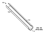
図1Aは、先行技術による割スリーブ10を示している。ここでは、割スリーブは、平らな状態に拡げられている。平らな状態で示されている割スリーブ10は、該割スリーブの互いに向き合った長手方向端における互いに向き合った終端12a,12bと、該割スリーブの互いに向き合った横方向端における2つの側部14a,14bと、側部14aから側部14bに延在する横方向寸法Tと、を有する実質的に矩形の形状を有しているとよい。割スリーブ10は、編組生地又はポリマーのようなどのような適切な材料から形成されていてもよく、好ましくは、形状記憶を可能とする材料から形成されている。例えば、割スリーブ10は、加熱によって形状硬化する材料から形成されているとよい。割スリーブ10をマンドレル又は他の装置の周りに転動させ、該割スリーブを適切な温度に加熱することによって、該割スリーブの形状が熱硬化され、これによって、外部付加力が作用しない限り、該割スリーブは、熱硬化された形状に戻る傾向にある。
FIG. 1A shows the
ケーブルの保護及び結束に用いられる一例では、割スリーブ10は、外部付加力が作用しない限り、該割スリーブの側部14aが側部14bの上に重なるように、形状硬化されている。図1Bは、側部14a,14bが互いに向かって部分的に丸められた部分的に弛緩した状態にあるこの形状硬化された形態の割スリーブ10を示している。開口(又は「切れ目(split)」16が割スリーブ10の長軸に沿って側部14a,14b間に形成されており、これによって、ケーブルを該割スリーブ内に挿入し、又はケーブルを該割スリーブから取り外すことができる。外部付加力が作用しない限り、割スリーブ10は、図1Cに示されているように、側部14aが側部14b上に重なる完全に弛緩した状態にある。この完全に弛緩した状態では、開口16は、事実上閉鎖されており、これによって、割スリーブ10内に位置するケーブルは、開口16内に固定され、ケーブルが側部14a,14b間において該割スリーブから非意図的に離脱する可能性が殆ど生じないことになる。
In one example used for cable protection and bundling, the
実際には、図1Bに示されている部分的に弛緩した状態をユーザーが得ることは、困難であることを理解されたい。例えば、もし割スリーブ10が数インチ超の長さを有していたなら、ユーザーが側部14a,14bを全長に沿って把持し、開口16を形成するように側部14a,14bを離間させることは、不可能ではないにしても、困難である。さらに正確にいえば、もし割スリーブ10がかなりの長さを有していたなら、ユーザーによって常に把持されていない側部14a,14bの部分は、互いに巻かれる傾向にあり、これによって、開口16は、概してユーザーによって積極的に把持された側部14a,14bの特定の部分間にしか割スリーブに存在しないことになる。この理由から、ユーザーが開口を生じさせることによって複数のケーブルを割スリーブ10内に挿入することが困難になり、及び/又は長い時間を必要とし、ユーザーは、開口16を生じさせるように割スリーブの側部14a,14bを操作し、同時にケーブルを該開口内に挿入するように操作しなければならない。以下に記載の工具と併せて用いられる割スリーブの例は、ニュージャージ州スパルタのTechFlex社によって製造されている5/16’’F6Woven Wrapである。
In practice, it should be understood that it is difficult for the user to obtain the partially relaxed state shown in FIG. 1B. For example, if the
図2A−2Bは、ケーブルを割スリーブ、例えば、前述の割スリーブ10内に取り付けるための工具100を示している。工具100は、中心部分110と、該中心部分に接続され、その半径方向外方に位置する横方向ガイド部分120a,120bと、を備えているとよい。中心部分110は、該中心部分の長手方向寸法と同一の長さLにわたって延在する管腔130を画定している。中心部分110は、横方向延長部110a,110bを備える略‘U’字状又は‘C’字状の開管の形態にあるとよい。横方向延長部110a,110bは、一端(図2Bにおける「底」端)において互いに接合されているが、他端(図2Bにおける「上」端)において互いに接合されていない。横方向延長部110a,110bが互いに接合されていない端に、ケーブル長孔140が画定されている。この長孔は、中心部分110の長さLにわたって長手方向に延在しており、かつ管腔130と連通している。図2Bに最もよく示されているように、横方向延長部110a,110bを備える中心部分110の断面は、円弧区分を形成している。但し、完全な円形から外れた形状も、同様に適切な機能をもたらすことになる。
FIG. 2A-2B shows a
ガイド部分120a,120bは、それぞれ、接続部分150a,150bを介して横方向延長部110a,110bに接続されているとよい。個別の構成部品として記載されているが、中心部分110、ガイド部分120a,120b、及び接続部分150a,150bは、それらの全てが単一の一体部材として形成されていてもよいし、又は接着剤、溶着等によって一緒に連結された個別の部材から形成されていてもよいことを理解されたい。ガイド部分120a,120bは、それぞれ、横方向延長部110a,110bの半径方向外方に位置している。この構成によって、長手方向長さLにわたって延在するスリーブガイド長孔160a,160bが、それぞれ、ガイド部分120aと横方向延長部110aとの間及びガイド部分120bと横方向延長部110bとの間に形成されることになる。スリーブガイド長孔160a,160bは、それぞれ、第1の端(図2Bにおける「上端」)において接続部分150a,150bによって封鎖されており、他端(図2Bにおける「底端」)において開いている。図2Bに最もよく示されているように、ガイド部分120a,120bの断面は、各々、円弧区分を形成している。但し、完全な円形から外れた形状も、同様に適切な機能をもたらすことになる。
The
以下、工具100の部分の種々の例示的な寸法について説明する。しかし、このような寸法は、単なる例示にすぎず、本発明の概念から逸脱することなく変更されてもよいことを理解されたい。例えば、例示的な寸法は、工具100と共に用いられる特定のケーブル及び/又は割スリーブに応じて変更されてもよい。加えて、図示されている実施形態において、工具100は、工具100の中心及びケーブル長孔140の中心を通って延在する長手方向面を中心として対称になっていることを理解されたい。ケーブル長孔140の幅D1は、約2mmから約5mmの間、例えば、約3.5mmであるとよい。横方向延長部110a,110bが円弧区分を形成している時、横方向延長部の内壁は、約5.5mmの曲率半径R1を有しているとよく、その外壁は、約7.5mmの曲率半径R2を有しているとよい。従って、横方向延長部110,110bの肉厚は、約2mmであるとよい。ガイド部分120a,120bが円弧区分を形成している時、ガイド部分の内壁は、約9mmの曲率半径R3を有しているとよく、その外壁は、約11mmの曲率半径R4を有しているとよい。従って、ガイド部分120a,120bの肉厚は、約2mmであるとよく、スリーブガイド長孔160a,160bの幅は、約1.5mmであるとよい。加えて、図示されている実施形態では、ガイド部分120a,120bの終端121a,121b及び中心部分110の底端の表面131は、いずれも単一平面P1又はその近傍で終端しているとよい。
Hereinafter, various exemplary dimensions of the portion of the
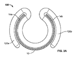
図3Aは、割スリーブ10の一部に組み込まれた工具100の断面を示している。この割スリーブの部分は、図1Bに示されているものと同様の部分的に弛緩した状態で工具によって保持されている。具体的には、割スリーブ10の一部は、該割スリーブの側部14a,14b間の長手方向に延在する中心部分をガイド部分120a,120bの終端121a,121b間に露出させながら、側部14aをガイド長孔160a内に摺動させ、側部14bをガイド長孔160b内に摺動させることによって、工具100に組み込まれるとよい。換言すれば、割スリーブの少なくとも一部、すなわち、長手方向に延在する中心部分は、工具100の部分によって画定された工具100の内部領域内に配置されていないことになる。図2に関連して前述したように、ガイド部分120a,120bの終端及び中心部分110の底端は、いずれも単一平面P1に終端するように配置されている。この構成によって、望ましくは、ガイド部分120a、120bは、接続部分150a,150bから該ガイド部分の終端に延在する十分な円弧長さを有し、これによって、割スリーブ10が工具100に組み込まれる時、割スリーブ10を容易に工具100に係合させることができ、さらに使用中に工具を割スリーブに組み込まれた状態で維持することができる。もしガイド部分120a,120bが接続部分150a,150bから延在する十分な円弧長さを有していなかったなら、例えば、割スリーブ10は、使用中に工具100との係合から容易に脱落する可能性がある。しかし、もしガイド部分120a,120bが、終端間の距離D2が割スリーブ10の横方向寸法に関する所定距離未満となるように接続部150aから延在する円弧長さを有していたなら、工具100を割スリーブ10に組み込むのが困難になるだろう。一実施形態では、工具100は、終端121a,121b間の距離D2が種々の横方向寸法Tを有する割スリーブ10を工具100と共に用いることができるように寸法決めされるように、構成されているとよい。例えば、図3Bに示されているように、もし割スリーブ10と同様の割スリーブ10’であって、その側部14a’から側部14b’に延在する横方向寸法が寸法Tよりも大きい、割スリーブ10’が工具100に組み込まれたなら、横方向寸法間の差に起因して、割スリーブ10’の長手方向に延在する中心部分11’は、ガイド部分120a,120bの終端間の開いた空間の中心部分から遠くに延出することになる。この場合、割スリーブ10’に関するこの実施形態では、部分11’は、中心部分110の底端の表面131上に又は実質的に該表面131に沿って延在しないことになる。
FIG. 3A shows a cross section of the
工具100が部分的に弛緩した状態にある割りスリーブ10の一部を保持している図3Aを再び参照すると、該割スリーブの管腔は、工具100の管腔130と実質的に同心になっている。同様に、割スリーブ10の開口16は、工具100のケーブル長孔140と長手方向において真っ直ぐに並んでいる。以下にさらに詳細に説明するように、割スリーブが図3Aに示されているように工具に組み込まれた時、1つ又は複数のケーブルを工具100の管腔130並びに割スリーブ10の管腔内に挿入することができる。
Revisiting FIG. 3A, where the
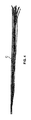
図4は、工具100及び割スリーブ10と併せて用いられるとよい複数のケーブルCを示している。別段の明示的な記述がない限り、ケーブル「(cable)」又は(cables)」という用語の使用は、単一ケーブル又は複数のケーブルのいずれかを指すものと理解されたい。但し、工具100は、複数のケーブルCを有するシステムに対して最も有用である。ケーブルCは、どのような他のシステムからも分離された状態で示されているが、工具100及び割スリーブ10を用いる環境は、一般的に、複数のケーブルCの各々の一端又は両端が他の構成部品内に取り付けられている環境である。
FIG. 4 shows a plurality of cables C that may be used in combination with the
図5Aは、工具100が終端12bに組み込まれた割スリーブ10の上斜視図である。工具100に組み込まれた割スリーブ10の部分が示されているが、この部分は、図3Aに関して前述した部分である。図5Aは、工具100に組み込まれた割スリーブ10の該部分が部分的に弛緩した状態(図1B)にあり、割スリーブ10の残りが完全に弛緩した状態(図1C)にあることを示している。図5Aに示されているように、工具100が割スリーブ10の終端12Bに組み込まれると、割スリーブの該終端は、ケーブルCが挿入される開口16をもたらすが、該割スリーブの残りは、閉じている。何故なら、該割スリーブの残りにおいて、割スリーブの側部14a,14bは、互いに接触しているか又は互いに重なっているからである。
FIG. 5A is an upper perspective view of the
図5Bは、(図5Aに示されている)工具100に組み込まれた終端12bにおける割スリーブ10の部分の拡大上斜視図である。図において、複数のケーブルCの一部が、割スリーブの開口16及び工具のケーブル長孔140を通って移動した後、管腔130内に配置されている。図5Bに示されているように、この構成では、ケーブルCの長さの大半は、割スリーブ10の外に位置している。いったん複数のケーブルCの一部が、最初に開口16及びケーブル長孔140を通って移動されたなら、ユーザーは、一方の手で割スリーブ10の終端12b(及びその内に位置するケーブルC)を把持し、他方の手で工具100を把持するとよい。次いで、ユーザーは、工具100を割スリーブ10の他の終端12aに向かって摺動させるとよい。
FIG. 5B is an enlarged perspective view of a portion of the
図5Cは、前述したように終端12aの方向に摺動した後に割スリーブ10の長さに沿って位置する工具100を有するシステムを示している。図から分かるように、工具100が割スリーブ10の長さに沿って摺動すると、工具100にもはや組み込まれていない割スリーブの一部、換言すれば、工具100に、もはや係合されていない割スリーブの一部は、完全に弛緩した状態に戻り、これによって、割スリーブは、工具100が摺動する方向と反対の方向において終端12aから離れる方に延在するケーブルCの長さ部分を完全に包囲し、割スリーブの管腔内に閉じ込めることになる。摺動中に、ユーザーは、ケーブルCを開口16及びケーブル長孔140を通して案内するために、指を該開口及びケーブル長孔の上に置くことが好ましい。ただし、これは、全ての場合に必ずしも必要ではない。
FIG. 5C shows a system having a
ユーザーが工具100を割スリーブ10の長さに沿って継続的に摺動させると、ケーブルCのさらなる長さ部分が、割スリーブの管腔内に案内されることになる。この手順は、図5Dに示されているように工具100が割スリーブ10の他の終端12aに達するまで継続される。この位置において、割スリーブ10の管腔の実質的に全ての長手方向長さ部分がそこに配置されたケーブルCの長さ部分を含み、これによって、ケーブルCのこのような長さ部分が割スリーブの内部に封入されることになる。図示されている状態では、割スリーブ10の管腔内の複数のケーブルCの部分は、適切かつ確実に結束されている。所望の長さのケーブルCを確保する所望の長さの割スリーブ10を提供することができることを理解されたい。前述のシステム及び方法によって、複数の割スリーブ10及び複数の対応する工具100がケーブルCの多数の組の複数のケーブルCを含むシステムに適用されてもよく、これによって、各組の複数のケーブルCを対応する工具100を用いることによって各割スリーブ10内に迅速に結束かつ固定することができることを理解されたい。後になって、もし複数のケーブルCの1つ又は複数が、保守、取換え、又は再配置を必要としたなら、ユーザーは、側部を互いに巻かれた状態に維持しようとする割スリーブの傾向に打ち勝つのに十分な力をケーブルに加えることによって、該ケーブルCを割スリーブ10から容易に引き出すことができる。次いで、前述の手順を繰り返すことによって、ケーブルCを割スリーブ10内に再び固定することができる。以下、前述の本発明の一般的な態様に対する多数の追加的な特徴及び変更形態について説明する。
When the user continuously slides the
割スリーブ210の代替的実施形態が、図6A−6Cに示されている。割スリーブ210は、以下に述べる特別の例外を除けば、殆ど全ての態様において割スリーブ10と同様である。例えば、割スリーブ210は、平らに拡げられた時、第1の終端212aから第2の終端212bに長手方向に延在すると共に第1の側部214aから第2の側部214bに横方向に延在する実質的に矩形形状を有しているとよい。割スリーブ10と同様、割スリーブ210は、形状硬化され、これによって、外部付加力が作用しない限り、第1の側部214aが第2の側部214bに重なる図6Cに示される形状を取るようになっているとよい。側部214a,214bを互いに離間するように引っ張る力を加えると、ケーブルCを挿入する開口216が形成されることになる。割スリーブ210は、以下に述べる例外を除いて、割スリーブ10に関して前述したのと全く同じように、工具100と相互作用するようになっているとよい。
An alternative embodiment of the
割スリーブ210の一方又は両方の終端212a,212bが、その残りよりも厚くなっているとよい。この実施形態は、任意の適切な方法によって、例えば、終端212a自体を折り返して圧着し、かつ終端212b自体を折り返して圧着することによって、又は追加的な材料帯片を、これらの終端に取り付けることによって、達成されるとよい。図6A−6Cにおいて、拡大厚み部がハッチングによって示されている。工具100が割スリーブ210に組み込まれると、ユーザーは、図5A−5Dに関連して説明したのと同じ方法によって、ケーブルCを割スリーブの管腔内に取り付ける。しかし、より厚い終端部分212a,212bがストッパをもたらし、これによって、工具100をより厚い終端から外すのが困難又は不可能になる。工具100のスリーブガイド長孔160a,160bが約1.5mmである前述の例では、終端部212a,212bは、好ましくは、約1.5mmよりも厚くなっている。
It is preferable that one or both
前述の割スリーブ210の場合、システムに対して準備される各割スリーブは、好ましくは、専用の工具100を備えている。一旦、スリーブ210及び対応する工具100が特定の複数のケーブルCを覆って取り付けられたなら、工具100は、スリーブ210に組み込まれた状態で維持される。もし後になってケーブルCの保守、取換え、又は再配置が必要となっても、工具100は、割スリーブ210に組み込まれたままである、何故なら、該工具は、意図的又は非意図的のいずれかに関わらず、割スリーブ210の端から離脱されないからである。割スリーブ210の厚い終端212a,212bによって、専用の工具100は、常に割スリーブに連結されており、必要に応じて、常にケーブルCを割スリーブ内に迅速かつ容易に固定することができることが、実際上保証されることになる。さらに、この構成によって、工具100が割スリーブ210から離脱するおそれを生じることなく、すでに互いに組み合わされたスリーブ210及び工具100をユーザーにもたらす能力が助長される。これによって、ユーザーが第1段階として工具100を割スリーブ210に押し込む状況が回避されることになる。
In the case of the
図7A−7Bは、ケーブルを割スリーブ、例えば、前述の割スリーブ10又は210内に取り付けるための工具300の他の実施形態を示している。工具300は、外側部分310と、該外側部分に接続され、その半径方向内方に位置する横方向ガイド部分320a,320bと、を備えている。外側部分310は、該外側部分を長手方向に貫通する管腔330を画定している。外側部分310は、横方向延長部310a,310bを備える略‘U’字状又は‘C’字状の開管の形態にあるとよい。横方向延長部310a,310bは、一端(図7Bにおける「底」端)において互いに接合されているが、他端(図7Bにおける「上」端)において接合されていない。横方向延長部310a,310bが互いに接合されていない端において、ケーブル長孔340が画定されている。この長孔は、外側部分310の長手方向寸法L2と同一長さにわたって延在しており、かつ管腔330と連通している。図7Bに最もよく示されているように、横方向延長部310a,310bの断面は、各々、円弧区分を形成しているとよい。但し、完全な円形から外れた形状であっても、同様の適切な機能をもたらすことになる。図示されている実施形態では、横方向延長部の外壁310a,310bは、約4mmから約7mmの間、例えば、約6mmの曲率半径R5を有しているとよい。
7A-7B show another embodiment of the
ガイド部分320a,320bは、それぞれ、接続部350a,350bを介して横方向延長部310a,310bに接続されているとよい。個別の構成要素として記載されているが、外側部分310、ガイド部分320a,320b、及び接続部分350a,350bは、それらの全てが単一の一体部材として形成されていてもよいし、又は接着剤、溶着等によって一緒に連結された個別部材として形成されていてもよいことを理解されたい。ガイド部分320a,320bは、それぞれ、接続部分350a,350bから横方向延長部310a,310bに向かって張り出しており、横方向延長部の半径方向内方に位置している。ガイド部分320a,320bの端部分322a,322bは、実質的に円形であるとよい。但し、これらは、必ずしも完全な円を形成している必要がない。図示されている実施形態では、ガイド部分320a,320bの端部分322a,322bは、約2mmから約3mmの間、例えば、約2.5mmの曲率半径を有しているとよい。この構成によって、スリーブガイド長孔360a,360bが、それぞれ、ガイド部分320aと横方向延長部310aとの間及びガイド部分320bと横方向延長部310bとの間に画定されている。スリーブガイド長孔360a,360bは、一般的に、工具100のスリーブガイド長孔160a,160bと同様の機能をもたらすようになっているとよい。例えば、スリーブガイド長孔360a,360bは、それぞれ、接続部分350a,350bによって、第1の端(図7Bにおける[上端])において封鎖されている。
The
以下、工具300の部分の種々の例示的な寸法について説明する。しかし、このような寸法は、単なる例示にすぎず、本発明の概念から逸脱することなく変更されてもよいことを理解されたい。例えば、例示的な寸法は、工具300と共に用いられる特定のケーブル及び/又は割スリーブに応じて変更されてもよい。加えて、図示されている実施形態では、工具300は、工具300の中心及びケーブル長孔340の中心を通って延在する長手方向平面を中心として対称的であることを理解されたい。ケーブル長孔340の幅D3は、約7mmから約11mmの間、例えば、約9mmであるとよい。スリーブガイド長孔360a,360bの幅は、約1mmから約2mmの間、例えば、約1.5mmであるとよい。
Hereinafter, various exemplary dimensions of the portion of the
図8は、割スリーブ10の一部に組み込まれた工具300の断面を示している。割スリーブのこの部分は、図1Bに示されているのと同様の部分的に弛緩した状態で工具によって保持されている。具体的には、割スリーブの一部は、側部14aをガイド長孔360a内に摺動させ、側部14bをガイド長孔360b内に摺動させることによって、工具300に組み込まれるとよい。工具100と工具300との間の大きな差は、以下の点、すなわち、工具300の図示されている構成では、工具300に組み込まれた割スリーブ10の一部は、工具300によって画定された内部領域内に事実上その全体が配置されているが、工具100の場合、割スリーブの少なくとも一部は、工具100によって画定された内部領域の外にある点にある。工具300の構成の利点は、割スリーブ10及び工具300が非意図的に分解されることがほぼ不可能であることにある。しかし、工具100と違って、工具300に組み込まれる割スリーブの寸法範囲が制限される。例えば、もしユーザーが図8に示されている第1及び第2の側部14a,14b間の横方向寸法よりも長い横方向寸法を有する割スリーブを組み立てようとしたなら、横方向寸法の過剰な長さ部分が、ケーブル長孔340に向かってかつケーブル長孔を通って上方に延び、ケーブルCを、ガイド長孔を通って管腔330内に効果的に挿入する能力を低下させる可能性がある。これを除けば、複数のケーブルを工具300に組み込まれた割スリーブ、例えば、割スリーブ10又は210内に配置する工具300を用いる手順は、工具100に関連して前述した手順と実質的に同じである。
FIG. 8 shows a cross section of the
図9は、追加された弾性フラップシステムを有する工具100の代替的実施形態を示している。図9は、割スリーブ10の一部に組み込まれた工具100’の断面を示している。工具100’は、殆どの点で工具100と同じである。例えば、工具100’は、それぞれ、接続部分150a’,150b’を介してガイド部分120a’,120b’に接続された横方向部分110a’,110b’を備えている。加えて、第1及び第2のフラップ170a’,170b’が、接続部分150a’,150b’に連結され、そこから延在しているとよい。第1及び第2のフラップは、互いに向かって延びているとよい。第1及び第2のフラップ170a’,170b’間に間隙が示されているが、代替的に、フラップは、互いに接触していてもよいし、又は互いにいくらか重なっていてもよい。しかし、いずれの場合も、フラップ170a’,170b’は、互いに直接連結されないようになっている。他の実施形態では、単一のフラップ170が1つの接続部分150a又は150bから他の接続部分150a又は150bに延びていてもよい。
FIG. 9 shows an alternative embodiment of the
複数のケーブルCを工具100の管腔130内に配置するための工具100に関して前述した手順において、望ましくは、ユーザーは、工具100が割スリーブに関して摺動する時にケーブルCを割スリーブ10内に押し付けるか又は押し込むために指をケーブルスリーブ長孔140の上に置くようになっている。工具100’の場合、フラップ170a’,170b’(又は単一のフラップ)がこの機能を効果的に果たすことになる。換言すれば、図示されている実施形態では、ケーブルCをフラップ170a’,170b’に対して押し付け、該フラップを管腔に向かって内方に屈曲させ、続いて、該ケーブルを、ケーブル長孔を通して工具100’の管腔内に押し込むことによって、ケーブルC を工具の管腔内に配置することができる。好ましくは、フラップ170a’,170b’は、ユーザーが意図的に力を加えた時にケーブルCの通過を可能にするように下方に撓むのに十分弾性的になっている。しかし、フラップ170a’,170b’は、工具100’が割スリーブ10に対して摺動する時にケーブルCが非意図的にフラップ170a’,170b’を通って工具から脱落することができないように、十分剛性であるべきある。また、もしフラップ170a’,170b‘間に間隙が存在していたなら、該間隙の大きさは、使用中にケーブルCが工具100’から非意図的に脱落するのに耐えるのに十分小さくなっているべきである。フラップ170a’,170b’は、工具100’と同じ材料から形成され、工具100’と一体になっているとよい。しかし、もし他の材料特性が望ましいなら、フラップ170a’,170b’は、他の材料からなる別の部材から形成され、例えば、接着剤によって工具100’に連結されていてもよい。フラップ170a’,170b’に関して前述したのと同じ機能をもたらす同様又は同一のフラップが、工具300の代替的実施形態に設けられてもよいことを理解されたい。
In the procedure described above with respect to the
工具100に対して前述したのと同様の弾性フラップシステムが、工具300のケーブル長孔開口340に設けられてもよいことを理解されたい。
It should be understood that the same elastic flap system as described above for the
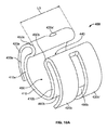
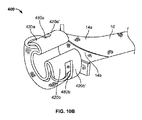
図10Aは、いくつかの点において工具100と同様の工具400の他の実施形態を示している。工具400は、横断面図において工具100と同様又は同一の形状を有しているとよい。例えば、工具400は、中心部分410と、該中心部分に接続され、その半径方向外方に位置する横方向ガイド部分と、を備えている。加えて、工具400は、2対の横方向ガイド部分、すなわち、工具の第1の側の横方向ガイド部分420a,420a’及び工具の第2の側の横方向ガイド部分420b,420b’を備えているとよい。ガイド部分420a,420’は、互いに離間しており、それらの間に(図10Aにおいて部番が付されていない)長孔480aを画定しており、ガイド部分420b,420b’は、それらの間に長孔480bを画定している。以下、図10B−10Cに関連して、長孔480a,480bについてさらに詳細に説明する。中心部分410は、該中心部分の長手方向寸法と同じ長さL3にわたって延在する管腔430を画定している。中心部分410は、横方向延長部410a,410bを備える略‘U’字状又は‘C’字状の開管の形態にあるとよい。横方向延長部410a,410bは、一端(図10Aの「底」端)において互いに接合されているが、他端(図10Aにおける[上]端)において互いに接合されていない。横方向延長部410a,410bが互いに接合されていない端において、ケーブル長孔440が画定されている。この長孔は、中心部分410の壁に沿って長手方向に延在しており、具体的には、中心部分410の長さL3にわたって長手方向に延在しており、かつ管腔430と連通している。
FIG. 10A shows another embodiment of the
対のガイド部分420a,420a’,420b,420b’は、それぞれ、接続部分450a,450bを介して横方向延長部410a,410bに接続されているとよい。個別の構成要素として記載されているが、中心部分410、ガイド部分420a,420a’,420b,420b’、及び接続部分450a,450bは、それらの全てが単一の一体部材として形成されていてもよいし、又は接着剤、溶着等によって一緒に連結された個別の部材として形成されていてもよいことを理解されたい。ガイド部分420a,420a’,420b,420b’は、それぞれ、横方向延長部410a,410bの半径方向外方に位置している。この構成によって、工具100と実質的に同じように,スリーブガイド長孔460a,460bが、それぞれ、ガイド部分420a,420a’と横方向延長部410aとの間及びガイド部分420b,420b’と横方向延長部410bとの間に形成されている。スリーブガイド長孔460a,460bは、それぞれ、接続部分450a,450bによって第1の端(図10Aにおける「上端」)において封鎖されており、他端(図10Aにおける「底端」)において開いている。
The pair of
前述の説明から明らかなように、複数のケーブルCを工具400に組み込まれた割スリーブ内に配置するために、工具400は、工具100と実質的に同じ方法によって、割スリーブ、例えば、割スリーブ10又は210と相互作用することができる。また、工具400’は、割スリーブの一端又は両端において「ストッパ(stop)」として作用することによって追加的な機能をもたらすようになっており、これによって、割スリーブ210の厚くなった終端212a,212bによって得られる機能と同様の機能をもたらすことができる。例えば、図10Bは、割スリーブ10の終端12aに組み込まれた工具400の上斜視図を示している。具体的には、終端12aの側部14aが横方向延長部410aと両ガイド部分420a,420a’との間に延び、これによって、該終端12aは、工具400を超えて位置することになる。次いで、この側部14aの終端12aは、折り返され、長孔480a内に引き込まれる。換言すれば、割スリーブ10の側部14aの一部は、ガイド部分420aの半径方向外方に位置し、他の部分は、ガイド部分420aと横方向延長部410aとの間に挟まれることになる。(割スリーブ10の長さに沿って長手方向に互いに離間した)割スリーブ10の側部14aの2つの部分は、互いに接触し、ガイド部分420a’と横方向延長部410aとの間に挟まれることになる。この構成は、図10Cにも示されている。この手順は、終端12aの側部14bに対して繰り返されることになる。すなわち、割スリーブ10の終端12aの側部14bは、両ガイド部分420b、420b’間を通され、次いで、ガイド部分420bの周りに折り返され、この後、ガイド部分420b’と横方向延長部410bとの間に通されることになる。この構成によれば、側部14a,14bのそれぞれの部分と工具400の部分との摩擦作用が、工具400を割スリーブ10の終端12aに効果的に係止することになる。1つの工具400が割スリーブ10の終端12aに設けられ、他の工具400が割スリーブ10の終端12bに設けられてもよい。ケーブルCを割スリーブ10内に配置させるための割スリーブ10に対する摺動機能を高めるために、第3の工具400が割スリーブ10の中央部に組み込まれてもよい。この構成は、割スリーブ10の一端又は両端にストッパとして機能する単一装置構造をもたらすようになっているが、ケーブルを割スリーブ10内に配置させるための摺動機構をもたらすこともできる。工具400は、摺動機能のために前述の工具のいずれかを用いながら、割スリーブ10の一端又は両端においてストッパとしてのみ用いられもよいことを理解されたい。また、工具400は、割スリーブ10又は210に対する摺動機能をもたらすことのみを目的として用いられてもよい。
As will be apparent from the above description, in order to place the plurality of cables C in a split sleeve built into the
本発明を特定の実施形態を参照して説明してきたが、これらの実施形態は、本発明の原理及び用途の単なる例示にすぎないことを理解されたい。それ故、例示的実施形態に対して多くの修正がなされてもよいこと、及び添付の請求項に規定されている本発明の精神及び範囲から逸脱することなく他の構成が考案されてもよいことを理解されたい。例えば、前述の一実施形態の特徴は、本発明の範囲から逸脱することなく、他の実施形態の特徴と組み合されてもよい。
[実施形態]
[実施形態1]
ケーブルを割スリーブ内に取り付けるための工具であって、
第1及び第2のガイド部分と、
前記第1のガイド部分から延在し,その半径方向外方に位置する第3の円弧状ガイド部分であって、前記第1及び第3のガイド部分は、それらの間に第1のガイド長孔を形成している、第3の円弧状ガイド部分と、
前記第2のガイド部分から延在し、その半径方向外方に位置する第4の円弧状ガイド部分であって、前記第2及び第4のガイド部分は、それらの間に第2のガイド長孔を形成している、第4の円弧状ガイド部分と、
を備える、工具。
[実施形態2]
前記第3及び第4のガイド部分は、それぞれの第1の端において互いに接合されており、
前記第3及び第4のガイド部分は,前記第1の端の反対側にそれぞれの第2の端を備えており、該第2の端は、互いに離間しており、
前記第2の端は、前記第1及び第2のガイド部分の互いに離間したそれぞれの第3の端と協働して、ケーブル長孔を画定している、
実施形態1に記載の工具。
[実施形態3]
前記第3及び第4のガイド部分は、それぞれの第1の端において互いに離間しており、
前記第3及び第4のガイド部分は、前記第1の端の反対側にそれぞれの第2の端を備えており、該第2の端は、互いに離間しており、
前記第2の端は、前記第1及び第2のガイド部分のそれぞれの第3の端と協働して、ケーブル長孔を画定している、
実施形態1に記載の工具。
[実施形態4]
ケーブルを割スリーブ内に取り付けるための工具であって、
第1及び第2の円弧状横方向延長部を有する中心部分と、
前記第1の横方向延長部から延在し,その半径方向外方に位置する第1の円弧状ガイド部分であって、前記第1のガイド部分及び前記第1の横方向延長部は、それらの間に第1のガイド長孔を形成している、第1の円弧状ガイド部分と、
前記第2の横方向延長部から延在し,その半径方向外方に位置する第2の円弧状ガイド部分であって、前記第2のガイド部分及び前記第2の横方向延長部は、それらの間に第2のガイド長孔を形成している、第2の円弧状ガイド部分と、
を備える、工具。
[実施形態5]
前記第1及び第2の横方向延長部及び前記第1及び第2のガイド部分は、各々、円弧区分を画定している、実施形態4に記載の工具。
[実施形態6]
前記第1のガイド部分は、第1の接続部分によって前記第1の横方向延長部に接続されており、前記第2のガイド部分は、第2の接続部分によって前記第2の横方向延長部に接続されている、実施形態4に記載の工具。
[実施形態7]
1つ又は複数のケーブルを受容するためのケーブル長孔を形成するために、前記第1及び第2の接続部分は、互いに離間している、実施形態6に記載の工具。
[実施形態8]
前記第1の接続部分又は前記第2の接続部分の少なくとも一方から離れる方に延在する少なくとも1つの弾性フラップ
をさらに備える、実施形態7に記載の工具。
[実施形態9]
前記少なくとも1つの弾性フラップは、前記ケーブル長孔に向う方又は前記ケーブル長孔から離れる方に撓むように構成されている、実施形態8に記載の工具。
[実施形態10]
前記少なくとも1つの弾性フラップは、前記第1の接続部分から前記第2の接続部分に向かって延在する第1の弾性フラップと、前記第2の接続部分から前記第1の接続部分に向かって延在する第2の弾性フラップとを含んでおり、前記第1及び第2の弾性フラップは、前記ケーブル長孔内において互いに連結されないようになっている、実施形態8に記載の工具。
[実施形態11]
前記第1のガイド部分の終端、前記第2のガイド部分の終端、及び前記中心部分の底は、単一平面に位置している、実施形態4に記載の工具。
[実施形態12]
前記第1のガイド長孔は、片側において前記第1の接続部分によって封鎖されており、前記第2のガイド長孔は、片側において前記第2の接続部分によって封鎖されている、実施形態6に記載の工具。
[実施形態13]
前記第1の横方向延長部の半径方向外方に位置する第3の円弧状ガイド部分であって、前記第1及び第3のガイド部分は、前記第1の横方向延長部分と協働して、前記第1のガイド長孔を形成している、第3の円弧状ガイド部分と、
前記第2の横方向延長部の半径方向外方に位置する第4の円弧状ガイド部分であって、前記第2及び第4のガイド部分は、前記第2の横方向延長部と協働して、前記第2のガイド長孔を形成している、第4の円弧状ガイド部分と、
をさらに備える、実施形態4に記載の工具。
[実施形態14]
前記第1及び第3のガイド部分は、互いに離間しており、それらの間に第1のスリーブ長孔を形成しており、前記第2及び第4のガイド部分は、互いに離間しており、それらの間に第2のスリーブ長孔を形成している、実施形態13に記載の工具。
[実施形態15]
1つ又は複数のケーブルを固定するためのシステムであって、
第1の終端から第2の終端に長手方向に延在すると共に第1の側部から第2の側部に横方向に延在する割スリーブであって、外部付加力が作用しない時、前記第1の側部が前記第2の側部に少なくとも部分的に重なる形態に付勢されている、割スリーブと、
前記割スリーブに組み込まれるように構成された工具であって、
第1及び第2の円弧状横方向延長部を有する中心部分と、
前記第1の横方向延長部の半径方向外方に位置する第1の円弧状ガイド部分であって、前記第1のガイド部分及び前記第1の横方向延長部は、それらの間に第1のガイド長孔を形成している、第1の円弧状ガイド部分と
前記第2の横方向延長部の半径方向外方に位置する第2の円弧状ガイド部分であって、前記第2のガイド部分及び前記第2の横方向延長部は、それらの間に第2のガイド長孔を形成している、第2の円弧状ガイド部分と、
を備える、工具と、
を備え、
前記割スリーブが前記工具に組み込まれた時、前記第1のガイド長孔は、前記割スリーブの前記第1の側部に沿って摺動するように構成されており、前記第2のガイド長孔は、前記割スリーブの前記第2の側部に沿って摺動するように構成されている、システム。
[実施形態16]
前記第1のガイド部分は、第1の接続部分によって前記第1の横方向延長部に接続されており、前記第2のガイド部分は、第2の接続部分によって前記第2の横方向延長部に接続されている、実施形態15に記載のシステム。
[実施形態17]
前記工具が前記割スリーブに組み込まれた時、前記割スリーブの前記第1の側部の一部は、前記第1の接続部分に隣接して位置し、前記割スリーブの前記第2の側部の一部は、前記第2の接続部分に隣接して位置するようになっている、実施形態16に記載のシステム。
[実施形態18]
前記工具が前記割スリーブに組み込まれた時、前記割スリーブの前記第1及び第2の側部間の部分は、片側のみが前記工具によって拘束されるようになっている、実施形態17に記載のシステム。
[実施形態19]
前記工具が前記割スリーブに組み込まれた時、ケーブル長孔が、前記第1及び第2の接続部分間に画定され、前記割スリーブの前記第1及び第2の側部の前記一部間に延び、1つ又は複数のケーブを受容するようになっている、実施形態17に記載のシステム。
[実施形態20]
第1の接続部分又は第2の接続部分の少なくとも一方から離れる方に延在する少なくとも1つの弾性フラップをさらに備える、実施形態19に記載のシステム。
[実施形態21]
前記少なくとも1つの弾性フラップは、前記ケーブル長孔に向う方又は前記ケーブル長孔から離れる方に撓むように構成されている、実施形態20に記載のシステム。
[実施形態22]
前記少なくとも1つの弾性フラップは、前記第1の接続部分から前記第2の接続部分に向かって延在する第1の弾性フラップと、前記第2の接続部分から前記第1の接続部分に向かって延在する前記第2の弾性フラップから延在する第2の弾性フラップとを含んでおり、前記第1及び第2の弾性フラップは、前記ケーブル長孔内において互いに連結されないようになっている、実施形態20に記載のシステム。
[実施形態23]
前記割スリーブの前記第1の終端は、第1の厚みを有しており、前記割スリーブの前記第2の終端は、第2の厚みを有しており、前記割スリーブの前記第1及び第2の終端間の中央部分は、第3の厚みを有しており、前記第1及び第2の厚みは、前記第3の厚みよりも大きくなっている、実施形態15に記載のシステム。
[実施形態24]
前記第1及び第2のガイド長孔は、各々、前記第3の厚みよりも大きく前記第1及び第2の厚みよりも小さい幅を有している、実施形態23に記載のシステム。
Although the present invention has been described with reference to specific embodiments, it should be understood that these embodiments are merely exemplary of the principles and uses of the invention. Therefore, many modifications may be made to the exemplary embodiments, and other configurations may be devised without departing from the spirit and scope of the invention as set forth in the appended claims. Please understand that. For example, the features of one embodiment described above may be combined with features of another embodiment without departing from the scope of the present invention.
[Embodiment]
[Embodiment 1]
A tool for attaching the cable inside the split sleeve
The first and second guide parts and
A third arcuate guide portion extending from the first guide portion and located outside the radial direction thereof, and the first and third guide portions have a first guide length between them. The third arc-shaped guide portion forming the hole and
A fourth arcuate guide portion extending from the second guide portion and located outside the radial direction thereof, and the second and fourth guide portions have a second guide length between them. The fourth arc-shaped guide portion forming the hole and
With tools.
[Embodiment 2]
The third and fourth guide portions are joined to each other at the first end of each.
The third and fourth guide portions are provided with their respective second ends on opposite sides of the first end, the second ends being separated from each other.
The second end cooperates with the respective third ends of the first and second guide portions separated from each other to define a cable slot.
The tool according to the first embodiment.
[Embodiment 3]
The third and fourth guide portions are separated from each other at the first end of each.
The third and fourth guide portions are provided with their respective second ends on opposite sides of the first end, the second ends being separated from each other.
The second end cooperates with the third end of each of the first and second guide portions to define a cable slot.
The tool according to the first embodiment.
[Embodiment 4]
A tool for attaching the cable inside the split sleeve
A central portion having first and second arcuate lateral extensions,
The first arc-shaped guide portion extending from the first lateral extension portion and located outside the radial direction thereof, and the first guide portion and the first lateral extension portion are those. A first arc-shaped guide portion forming a first guide slot between the two, and
The second arc-shaped guide portion extending from the second lateral extension portion and located outside the radial direction thereof, and the second guide portion and the second lateral extension portion are those. A second arc-shaped guide portion forming a second guide slot between the two,
With tools.
[Embodiment 5]
The tool according to the fourth embodiment, wherein the first and second lateral extension portions and the first and second guide portions each define an arc division.
[Embodiment 6]
The first guide portion is connected to the first lateral extension portion by a first connecting portion, and the second guide portion is connected to the second lateral extension portion by a second connecting portion. The tool according to embodiment 4, which is connected to.
[Embodiment 7]
The tool according to embodiment 6, wherein the first and second connecting portions are separated from each other in order to form a cable slot for receiving one or more cables.
[Embodiment 8]
At least one elastic flap extending away from at least one of the first connecting portion or the second connecting portion
7. The tool according to embodiment 7.
[Embodiment 9]
The tool according to embodiment 8, wherein the at least one elastic flap is configured to bend toward the cable slot or away from the cable slot.
[Embodiment 10]
The at least one elastic flap includes a first elastic flap extending from the first connecting portion toward the second connecting portion and the second connecting portion toward the first connecting portion. The tool according to embodiment 8, wherein the first and second elastic flaps include an extending second elastic flap so that the first and second elastic flaps are not connected to each other in the cable slot.
[Embodiment 11]
The tool according to embodiment 4, wherein the end of the first guide portion, the end of the second guide portion, and the bottom of the central portion are located on a single plane.
[Embodiment 12]
In the sixth embodiment, the first guide elongated hole is closed by the first connecting portion on one side, and the second guide elongated hole is closed by the second connecting portion on one side. Described tools.
[Embodiment 13]
A third arc-shaped guide portion located outside the radial direction of the first lateral extension portion, and the first and third guide portions cooperate with the first lateral extension portion. The third arc-shaped guide portion forming the first guide elongated hole and the third arc-shaped guide portion
A fourth arc-shaped guide portion located outside the radial direction of the second lateral extension portion, and the second and fourth guide portions cooperate with the second lateral extension portion. The fourth arc-shaped guide portion forming the second guide elongated hole and the fourth arc-shaped guide portion
The tool according to the fourth embodiment.
[Embodiment 14]
The first and third guide portions are separated from each other and form a first sleeve slot between them, and the second and fourth guide portions are separated from each other. The tool according to embodiment 13, wherein a second sleeve slot is formed between them.
[Embodiment 15]
A system for fixing one or more cables
A split sleeve that extends longitudinally from the first end to the second end and extends laterally from the first side to the second side, and when no external additional force acts, the above. A split sleeve and a split sleeve in which the first side portion is urged to overlap the second side portion at least partially.
A tool configured to be incorporated into the split sleeve.
A central portion having first and second arcuate lateral extensions,
A first arc-shaped guide portion located on the outer side in the radial direction of the first lateral extension portion, the first guide portion and the first lateral extension portion have a first structure between them. With the first arc-shaped guide portion forming the guide elongated hole of
A second arcuate guide portion located radially outward of the second lateral extension portion, the second guide portion and the second lateral extension portion having a second between them. The second arc-shaped guide portion forming the guide slot of
With tools and
With
When the split sleeve is incorporated into the tool, the first guide slot is configured to slide along the first side of the split sleeve and the second guide length. A system in which the holes are configured to slide along the second side of the split sleeve.
[Embodiment 16]
The first guide portion is connected to the first lateral extension portion by a first connecting portion, and the second guide portion is connected to the second lateral extension portion by a second connecting portion. 15. The system according to embodiment 15, which is connected to.
[Embodiment 17]
When the tool is incorporated into the split sleeve, a portion of the first side portion of the split sleeve is located adjacent to the first connecting portion and the second side portion of the split sleeve. 16. The system of
[Embodiment 18]
13. The 17th embodiment, wherein when the tool is incorporated into the split sleeve, only one side of the portion between the first and second sides of the split sleeve is constrained by the tool. System.
[Embodiment 19]
When the tool is incorporated into the split sleeve, a cable slot is defined between the first and second connecting portions and between the first and second side portions of the split sleeve. 17. The system according to embodiment 17, which extends to accept one or more caves.
[Embodiment 20]
19. The system of embodiment 19, further comprising at least one elastic flap extending away from at least one of the first or second connection.
[Embodiment 21]
20. The system of embodiment 20, wherein the at least one elastic flap is configured to bend towards or away from the cable slot.
[Embodiment 22]
The at least one elastic flap includes a first elastic flap extending from the first connecting portion toward the second connecting portion and the second connecting portion toward the first connecting portion. A second elastic flap extending from the second elastic flap extending is included, and the first and second elastic flaps are prevented from being connected to each other in the cable slot. The system according to embodiment 20.
[Embodiment 23]
The first end of the split sleeve has a first thickness, the second end of the split sleeve has a second thickness, and the first and second ends of the split sleeve. The system according to embodiment 15, wherein the central portion between the second ends has a third thickness, the first and second thicknesses being greater than the third thickness.
[Embodiment 24]
23. The system according to embodiment 23, wherein the first and second guide holes each have a width larger than the third thickness and smaller than the first and second thicknesses.
Claims (15)
第1の終端から第2の終端に長手方向に延在すると共に第1の側部(14a)から第2の側部(14b)に横方向に延在する割スリーブ(10)であって、外部付加力が作用しない時、前記第1の側部(14a)が前記第2の側部(14b)に少なくとも部分的に重なる形態に付勢されている、割スリーブ(10)と、
前記割スリーブ(10)に組み込まれるように構成され、及び組み込まれた状態で維持されるように構成された専用の工具であって、
一端において互いに接合された第1及び第2の円弧状横方向延長部(110a,110b)を有する開管の形態の中心部分(110)と、
前記第1の円弧状横方向延長部(110a)から延在し,その半径方向外方に位置する第1の円弧状ガイド部分(120a)であって、前記第1の円弧状ガイド部分(120a)及び前記第1の円弧状横方向延長部(110a)は、それらの間に第1のガイド長孔(160a)を形成している、第1の円弧状ガイド部分(120a)と、
前記第2の円弧状横方向延長部(110b)から延在し,その半径方向外方に位置する第2の円弧状ガイド部分(120b)であって、前記第2の円弧状ガイド部分(120b)及び前記第2の円弧状横方向延長部(110b)は、それらの間に第2のガイド長孔(160b)を形成している、第2の円弧状ガイド部分(120b)と、
を備える専用の工具とを備え、
前記割スリーブ(10)が前記専用の工具に組み込まれた時、前記第1のガイド長孔(160a)は、前記割スリーブ(10)の前記第1の側部(14a)に沿って摺動するように構成されており、前記第2のガイド長孔(160b)は、前記割スリーブ(10)の前記第2の側部(14b)に沿って摺動するように構成されている、システム。 A system for fixing one or more cables
A split sleeve (10) extending longitudinally from the first end to the second end and laterally extending from the first side (14a) to the second side (14b) . With the split sleeve (10) , the first side portion (14a) is urged to at least partially overlap the second side portion (14b) when no external additional force acts.
A dedicated tool configured to be incorporated into and maintained in the split sleeve (10).
A central portion (110) in the form of an open tube having first and second arcuate lateral extensions (110a, 110b) joined to each other at one end .
Extending from said first arcuate lateral extension (110a), a first arc-shaped guide portion located radially outward (120a), said first arcuate guide portion (120a ) And the first arc-shaped lateral extension portion (110a) , the first arc-shaped guide portion (120a) forming the first guide elongated hole (160a) between them, and the first arc-shaped guide portion (120a).
Extending from the second arcuate lateral extension (110b), a second arcuate guide portion located radially outward (120b), said second arc-shaped guide portion (120b ) And the second arcuate lateral extension portion (110b) have a second arcuate guide portion (120b) forming a second guide elongated hole (160b) between them.
Equipped with a dedicated tool and
When the split sleeve (10) is incorporated into the dedicated tool, the first guide slot (160a) slides along the first side portion (14a) of the split sleeve (10). The second guide slot (160b) is configured to slide along the second side portion (14b) of the split sleeve (10). ..
をさらに備える、請求項4に記載のシステム。 At least one elastic flap (170a', 170b') extending away from at least one of the first connecting portion (150a') or the second connecting portion (150b').
4. The system according to claim 4.
前記第2の円弧状横方向延長部(110b)の半径方向外方に位置する第4の円弧状ガイド部分であって、前記第2及び第4の円弧状ガイド部分は、前記第2の円弧状横方向延長部(110b)と協働して、前記第2のガイド長孔(160b)を形成している、第4の円弧状ガイド部分と、
をさらに備える、請求項1に記載のシステム。 The third arc-shaped guide portion located outside the radial direction of the first arc-shaped lateral extension portion (110a) , and the first and third arc-shaped guide portions are the first circle. A third arc-shaped guide portion forming the first guide elongated hole (160a) in cooperation with the arc-shaped lateral extension portion (110a), and a third arc-shaped guide portion.
The fourth arc-shaped guide portion located outside the radial direction of the second arc-shaped lateral extension portion (110b) , and the second and fourth arc-shaped guide portions are the second circle. A fourth arc-shaped guide portion forming the second guide elongated hole (160b) in cooperation with the arc-shaped lateral extension portion (110b), and a fourth arc-shaped guide portion.
The system according to claim 1, further comprising.
Applications Claiming Priority (3)
| Application Number | Priority Date | Filing Date | Title |
|---|---|---|---|
| US14/750,335 | 2015-06-25 | ||
| US14/750,335 US10270232B2 (en) | 2015-06-25 | 2015-06-25 | Apparatus for installing cables in split sleeve |
| PCT/US2016/039031 WO2016210139A1 (en) | 2015-06-25 | 2016-06-23 | Apparatus for installing cables in split sleeve |
Publications (3)
| Publication Number | Publication Date |
|---|---|
| JP2018518932A JP2018518932A (en) | 2018-07-12 |
| JP2018518932A5 JP2018518932A5 (en) | 2019-07-25 |
| JP6839098B2 true JP6839098B2 (en) | 2021-03-03 |
Family
ID=57585883
Family Applications (1)
| Application Number | Title | Priority Date | Filing Date |
|---|---|---|---|
| JP2017559555A Active JP6839098B2 (en) | 2015-06-25 | 2016-06-23 | A device for attaching a cable inside a split cable |
Country Status (7)
| Country | Link |
|---|---|
| US (1) | US10270232B2 (en) |
| EP (1) | EP3314708B1 (en) |
| JP (1) | JP6839098B2 (en) |
| CN (1) | CN107615606B (en) |
| ES (1) | ES2802293T3 (en) |
| PT (1) | PT3314708T (en) |
| WO (1) | WO2016210139A1 (en) |
Families Citing this family (1)
| Publication number | Priority date | Publication date | Assignee | Title |
|---|---|---|---|---|
| EP3984103A1 (en) * | 2019-06-17 | 2022-04-20 | Lisa Dräxlmaier GmbH | Tool for fitting a conduit onto a cable, and production method |
Family Cites Families (22)
| Publication number | Priority date | Publication date | Assignee | Title |
|---|---|---|---|---|
| US396677A (en) * | 1889-01-22 | Device for fastening conductors | ||
| US2519987A (en) * | 1945-03-28 | 1950-08-22 | Eugene B Wernette | Clothespin |
| US4120289A (en) * | 1977-04-20 | 1978-10-17 | Bottum Edward W | Refrigerant charged solar water heating structure and system |
| US4593442A (en) | 1985-06-17 | 1986-06-10 | Wright Curtis M | Cable installation apparatus |
| JPH071968B2 (en) | 1989-08-12 | 1995-01-11 | 西部電気工業株式会社 | Vertical flexible tube cable attachment / detachment device |
| US5316247A (en) | 1992-07-01 | 1994-05-31 | Minnesota Mining And Manufacturing Company | Wire-and-tube-retaining pole clip |
| FR2761826B1 (en) | 1997-04-04 | 1999-07-02 | Bentley Harris Sa | CABLE SHEATHING TOOL AND METHOD |
| ES2217631T3 (en) * | 1999-03-02 | 2004-11-01 | Richco Italia S.R.L. | DEVICE FOR INSERTING WIRES AND / OR PIPES IN A FLEXIBLE TUBULAR LINING PROVIDED WITH SOLAPANING EDGES THAT CAN BE OPENED. |
| CN2434811Y (en) * | 2000-05-10 | 2001-06-13 | 美星国际有限公司 | Inducing clips and wire protective sleeve |
| FR2835360B1 (en) * | 2002-01-28 | 2004-04-23 | France Telecom | TOOL FOR GEARING AT LEAST ONE CABLE IN A LONGITUDINALLY SLOTTED SHEATH, AND GEAR DEVICE COMPRISING SUCH A TOOL |
| US6749179B2 (en) | 2002-03-13 | 2004-06-15 | Board Of Regents, The University Of Texas System | Devices and methods for placing wiring into split loom tubing |
| US6766833B1 (en) * | 2003-01-13 | 2004-07-27 | Heshan Jian Hao Lighting Ind. Co., Ltd. | Device for inserting wires into a tubular sheath |
| US7076862B2 (en) * | 2003-08-06 | 2006-07-18 | International Business Machines Corporation | System, method, and apparatus for installing and removing flat cable with respect to a protective sleeve |
| US20050048640A1 (en) * | 2003-08-25 | 2005-03-03 | Gen-Probe Incorporated | Clamp and method of making same |
| US7183489B2 (en) * | 2003-09-24 | 2007-02-27 | Panduit Corp. | Multi-port compression connector |
| US7137181B2 (en) * | 2004-05-03 | 2006-11-21 | Juan Triola Ifort | Flexible cable sleeve apparatus |
| DE102006062544B4 (en) | 2006-12-29 | 2012-10-18 | Flexa Gmbh & Co. Produktion Und Vertrieb Kg | Arrangement and closure element for assembling protective tubes and cables, lines, and the like incorporated therein |
| DE102006062545B4 (en) | 2006-12-29 | 2008-09-18 | Flexa Gmbh & Co. Produktion Und Vertrieb Kg | Auxiliary tool, set with an auxiliary tool, a protective tube and a closure element and arrangement with a supply of a protective tube and an auxiliary tool |
| DE102007001981A1 (en) | 2007-01-08 | 2008-07-10 | Carl Freudenberg Kg | fastener |
| EP2425186A2 (en) * | 2009-04-27 | 2012-03-07 | Kingspan Holdings (IRL) Limited | A solar collector |
| CN102741723B (en) * | 2011-10-09 | 2014-01-22 | 华为技术有限公司 | Apparatus and method for laying pigtails |
| CN203431309U (en) * | 2013-08-27 | 2014-02-12 | 重庆长安汽车股份有限公司 | Oil pipe fixing clamp |
-
2015
- 2015-06-25 US US14/750,335 patent/US10270232B2/en active Active
-
2016
- 2016-06-23 WO PCT/US2016/039031 patent/WO2016210139A1/en active Application Filing
- 2016-06-23 CN CN201680029096.1A patent/CN107615606B/en active Active
- 2016-06-23 JP JP2017559555A patent/JP6839098B2/en active Active
- 2016-06-23 EP EP16815307.0A patent/EP3314708B1/en active Active
- 2016-06-23 PT PT168153070T patent/PT3314708T/en unknown
- 2016-06-23 ES ES16815307T patent/ES2802293T3/en active Active
Also Published As
| Publication number | Publication date |
|---|---|
| EP3314708A4 (en) | 2018-06-13 |
| PT3314708T (en) | 2020-06-30 |
| CN107615606B (en) | 2020-01-17 |
| ES2802293T3 (en) | 2021-01-18 |
| JP2018518932A (en) | 2018-07-12 |
| EP3314708A1 (en) | 2018-05-02 |
| US20160375567A1 (en) | 2016-12-29 |
| US10270232B2 (en) | 2019-04-23 |
| EP3314708B1 (en) | 2020-04-08 |
| WO2016210139A1 (en) | 2016-12-29 |
| CN107615606A (en) | 2018-01-19 |
Similar Documents
| Publication | Publication Date | Title |
|---|---|---|
| JP5743882B2 (en) | Needle safety device and intravenous catheter device | |
| JP5922246B2 (en) | Hose clamp | |
| JP5769253B2 (en) | Device for fixing elastic cord | |
| US20100125979A1 (en) | Tightenable Clamping Device, Suitable For Application In Tie Wraps | |
| KR101533611B1 (en) | steel reinforcement connecting device | |
| EP2637490A1 (en) | Ferrite clamp | |
| JP6839098B2 (en) | A device for attaching a cable inside a split cable | |
| AU2017252490B2 (en) | Guide apparatus | |
| JP7012869B2 (en) | Clamp | |
| MX2013014023A (en) | Devices and methods for securing tissue. | |
| JP4915276B2 (en) | Protector | |
| JP6155396B2 (en) | Hose clamp | |
| JP5438508B2 (en) | Noise absorber | |
| JP2006054977A (en) | Mounting jig for corrugated tube | |
| KR20170038560A (en) | Cable tie | |
| KR102347139B1 (en) | Fixed band with locking structure | |
| JP6175850B2 (en) | Clip cartridge and clip device | |
| KR102178130B1 (en) | Catheter fixing band and method for fixing catheter using the same | |
| JP5698320B2 (en) | Loose leaf binding | |
| JP5944105B2 (en) | Tie fastener | |
| WO2016055845A1 (en) | Reusable clamping spine for clamping leaves | |
| JP7216942B1 (en) | cord reel | |
| JP2018518932A5 (en) | ||
| JP2023038434A (en) | Wiring harness | |
| TWM566660U (en) | Rotary loose-leaf apparatus |
Legal Events
| Date | Code | Title | Description |
|---|---|---|---|
| A521 | Request for written amendment filed |
Free format text: JAPANESE INTERMEDIATE CODE: A523 Effective date: 20190621 |
|
| A621 | Written request for application examination |
Free format text: JAPANESE INTERMEDIATE CODE: A621 Effective date: 20190621 |
|
| A131 | Notification of reasons for refusal |
Free format text: JAPANESE INTERMEDIATE CODE: A131 Effective date: 20200731 |
|
| A601 | Written request for extension of time |
Free format text: JAPANESE INTERMEDIATE CODE: A601 Effective date: 20201030 |
|
| A521 | Request for written amendment filed |
Free format text: JAPANESE INTERMEDIATE CODE: A523 Effective date: 20201221 |
|
| TRDD | Decision of grant or rejection written | ||
| A01 | Written decision to grant a patent or to grant a registration (utility model) |
Free format text: JAPANESE INTERMEDIATE CODE: A01 Effective date: 20210126 |
|
| A61 | First payment of annual fees (during grant procedure) |
Free format text: JAPANESE INTERMEDIATE CODE: A61 Effective date: 20210212 |
|
| R150 | Certificate of patent or registration of utility model |
Ref document number: 6839098 Country of ref document: JP Free format text: JAPANESE INTERMEDIATE CODE: R150 |
|
| R250 | Receipt of annual fees |
Free format text: JAPANESE INTERMEDIATE CODE: R250 |