JP6837775B2 - Work machine - Google Patents
Work machine Download PDFInfo
- Publication number
- JP6837775B2 JP6837775B2 JP2016154969A JP2016154969A JP6837775B2 JP 6837775 B2 JP6837775 B2 JP 6837775B2 JP 2016154969 A JP2016154969 A JP 2016154969A JP 2016154969 A JP2016154969 A JP 2016154969A JP 6837775 B2 JP6837775 B2 JP 6837775B2
- Authority
- JP
- Japan
- Prior art keywords
- boom
- hole
- pin hole
- pin
- protrusion
- Prior art date
- Legal status (The legal status is an assumption and is not a legal conclusion. Google has not performed a legal analysis and makes no representation as to the accuracy of the status listed.)
- Active
Links
Images


Landscapes
- Shovels (AREA)
Description
本発明は、作業機および取付方法に関する。 The present invention relates to a working machine and a mounting method.
建築物等の解体に用いる作業車両の作業機は、作業の高さや作業の種類(ガラ収集や積み込み)などによって、複数のアタッチメントを交換可能なように構成されている(例えば、特許文献1参照。)。
例えば、特許文献1に示す作業車両には、ベースマシンに取り付け可能な基本セパレート仕様、継ぎ足しセパレートブーム仕様、または解体バックホウ仕様のアタッチメントが設けられている。
The work machine of the work vehicle used for dismantling a building or the like is configured so that a plurality of attachments can be exchanged depending on the height of work and the type of work (collection and loading of glass) (see, for example, Patent Document 1). .).
For example, the work vehicle shown in Patent Document 1 is provided with an attachment having a basic separate specification, a replenishing separate boom specification, or a dismantling backhoe specification that can be attached to a base machine.
それぞれのアタッチメントは基端側にブームを有しており、該ブームが、ベースマシンに設けられているブームに着脱可能に取り付けられる。これにより、ベースマシンに複数のアタッチメントを交換可能に取り付けることができる。 Each attachment has a boom on the proximal end side, and the boom is detachably attached to a boom provided on the base machine. This allows multiple attachments to be interchangeably attached to the base machine.
しかしながら、アタッチメントは、長尺物であり重量が重いため、ベースマシンのブームに、アタッチメントのブームを取り付ける作業は困難であり、時間が掛かっていた。
本発明は、上記従来の課題を考慮し、ブーム間における取り付け作業を容易に行うことが可能な作業機および取付方法を提供することを目的とする。
However, since the attachment is long and heavy, it is difficult and time-consuming to attach the boom of the attachment to the boom of the base machine.
It is an object of the present invention to provide a working machine and a mounting method capable of easily performing mounting work between booms in consideration of the above-mentioned conventional problems.
上記目定を達成するために、第1の発明に係る作業機は、第1ブームと、第1ブームに着脱可能に取り付けられる第2ブームとを備えた作業機であって、保持部と、連結部と、を備える。保持部は、第1ブームに第2ブームを保持する。連結部は、第1ブームと第2ブームを連結する。保持部は、連結部で連結されていない状態において、第2ブームを第1ブームに対して回動可能に連結する。連結部は、第1ピン孔と、第2ピン孔と、第1突部と、第2突部と、を有する。第1ピン孔は、第1ブームに形成されている。第2ピン孔は、第2ブームに形成されている。第1突部は、保持部を中心にして第2ブームを第1ブームに向けて回動する回動方向側の第1ピン孔の周囲に設けられている。第2突部は、第2ピン孔の周囲に設けられている。第1突部に第2突部が当接した状態において、第1ピン孔と第2ピン孔が対向する。 In order to achieve the above-mentioned determination, the working machine according to the first invention is a working machine including a first boom and a second boom detachably attached to the first boom, and includes a holding portion and a holding portion. It is provided with a connecting portion. The holding portion holds the second boom on the first boom. The connecting portion connects the first boom and the second boom. The holding portion rotatably connects the second boom to the first boom in a state where it is not connected by the connecting portion. The connecting portion has a first pin hole, a second pin hole, a first protrusion, and a second protrusion. The first pin hole is formed in the first boom. The second pin hole is formed in the second boom. The first protrusion is provided around the first pin hole on the rotation direction side that rotates the second boom toward the first boom around the holding portion. The second protrusion is provided around the second pin hole. The first pin hole and the second pin hole face each other in a state where the second protrusion is in contact with the first protrusion.
ここで、保持部において第1ブームと第2ブームを連結した状態で、例えば、第1ブームを持ち上げると、第2ブームが第1ブーム側に向かって回動する。この回動により、第2突部が第1突部に当接すると、第1ピン孔と第2ピン孔が対向し第1ピン孔と第2ピン孔の位置合わせが完了した状態となる。そして、位置合わせが完了した第1ピン孔と第2ピン孔に第2ピンを挿入することにより、連結部において第1ブームと第2ブームを連結することができる。このように、第1ブームに第2ブームを保持部で保持し連結部で連結することにより、第1ブームに第2ブームを固定することができる。 Here, when the first boom is lifted, for example, with the first boom and the second boom connected in the holding portion, the second boom rotates toward the first boom side. When the second protrusion comes into contact with the first protrusion due to this rotation, the first pin hole and the second pin hole face each other, and the alignment of the first pin hole and the second pin hole is completed. Then, by inserting the second pin into the first pin hole and the second pin hole for which the alignment has been completed, the first boom and the second boom can be connected at the connecting portion. In this way, the second boom can be fixed to the first boom by holding the second boom on the first boom with the holding portion and connecting the second boom with the connecting portion.
以上のように、保持部で保持した状態において第1ブームを持ち上げるだけで、第1ブームに第2ブームを取り付けることが可能となり、ブーム間における取り付け作業を容易に行うことができる。
これにより、例えば、第1ブームが作業車両に取付られており、第2ブームがアタッチメントに含まれる場合には、作業車両にアタッチメントを容易に取り付けることができる。
As described above, the second boom can be attached to the first boom simply by lifting the first boom while being held by the holding portion, and the attachment work between the booms can be easily performed.
Thereby, for example, when the first boom is attached to the work vehicle and the second boom is included in the attachment, the attachment can be easily attached to the work vehicle.
第2の発明に係る作業機は、第1の発明に係る作業機であって、第2ブームは、第2ブーム本体と、第2ブーム本体の端に固定されたブラケットと、を有する。第2ピン孔および第2突部は、ブラケットに設けられている。
これによって、ブラケットを有する第2ブームについても、容易に第1ブームに取り付けることができる。
The working machine according to the second invention is the working machine according to the first invention, and the second boom has a second boom main body and a bracket fixed to an end of the second boom main body. The second pin hole and the second protrusion are provided on the bracket.
As a result, the second boom having the bracket can be easily attached to the first boom.
第3の発明に係る作業機は、第1の発明に係る作業機であって、連結部は、第1ピン孔に対向する貫通孔を持ち、第1ブームに配置された円筒部を更に有する。第1突部は、第1ピン孔に沿って円筒部から突出して形成されている。第1突部の第1ピン孔に沿った内周面は、貫通孔の内周面と同一面である。第1突部と円筒部は、一体的に構成されている。 The working machine according to the third invention is the working machine according to the first invention, and the connecting portion has a through hole facing the first pin hole, and further has a cylindrical portion arranged in the first boom. .. The first protrusion is formed so as to project from the cylindrical portion along the first pin hole. The inner peripheral surface of the first protrusion along the first pin hole is the same surface as the inner peripheral surface of the through hole. The first protrusion and the cylindrical portion are integrally formed.
これにより、1つの部材から第1突部と円筒部を形成することが可能となり、第1ピン孔に対して第1突部の位置を精度良く配置することができる。例えば、一つの部材に対して1つの貫通孔を作成することにより円筒部の貫通孔と第1突部の内周面とを同時に形成することができる。そのため、円筒部の貫通孔の中心と第1ピン孔の中心とを合わせるように円筒部を配置することにより第1突部の内周面の中心も第1ピン孔の中心と一致し、第1ピン孔に対応して第1突部を精度良く配置することができる。 As a result, the first protrusion and the cylindrical portion can be formed from one member, and the position of the first protrusion can be accurately arranged with respect to the first pin hole. For example, by creating one through hole for one member, the through hole of the cylindrical portion and the inner peripheral surface of the first protrusion can be formed at the same time. Therefore, by arranging the cylindrical portion so that the center of the through hole of the cylindrical portion and the center of the first pin hole are aligned with each other, the center of the inner peripheral surface of the first protrusion also coincides with the center of the first pin hole. The first protrusion can be accurately arranged corresponding to the 1-pin hole.
第4の発明に係る作業機は、第3の発明に係る作業機であって、連結部は、第1ピン孔に配置された第1ブシュを有する。第1ブシュは、第1ピン孔から幅方向に沿って突出した突出部を持つ。貫通孔は、第1ピン孔と同じ半径である。円筒部は、突出部の周囲に配置されている。
このように、第1ピン孔に配置されたブシュの突出部を基準に円筒部を配置することができるため、円筒部の中心が第1ピン孔の中心に一致するように円筒部を容易に配置することができる。
The working machine according to the fourth invention is the working machine according to the third invention, and the connecting portion has a first bush arranged in the first pin hole. The first bush has a protrusion protruding along the width direction from the first pin hole. The through hole has the same radius as the first pin hole. The cylindrical portion is arranged around the protrusion.
In this way, since the cylindrical portion can be arranged with reference to the protruding portion of the bush arranged in the first pin hole, the cylindrical portion can be easily arranged so that the center of the cylindrical portion coincides with the center of the first pin hole. Can be placed.
第5の発明に係る作業機は、第1の発明に係る作業機であって、保持部は、第1ピンと、ピン支持部と、を有する。第1ピンは、第2ブームに設けられている。ピン支持部は、連結部で第1ブームと第2ブームが連結されていない状態において第1ピンを回動可能に支持し、第1ブームに設けられている。ピン支持部は、幅方向に沿って形成され第1ピンが通過可能な切り欠き部を持つ。 The working machine according to the fifth invention is the working machine according to the first invention, and the holding portion has a first pin and a pin supporting portion. The first pin is provided on the second boom. The pin support portion rotatably supports the first pin in a state where the first boom and the second boom are not connected by the connecting portion, and is provided on the first boom. The pin support portion is formed along the width direction and has a notch portion through which the first pin can pass.
これにより、切り欠き部を通して第1ピンをピン支持部に配置することで、容易に第2ブームを第1ブームに対して回動可能に連結することができる。
第6の発明に係る作業機は、第1の発明に係る作業機であって、第2突部は、第2ピン孔に配置された第2ブシュによって形成される。
これにより、容易に第2ピン孔に対する第2突部の位置も精度良く配置することが可能となり、ブシュが第1突部に当接することにより、第1ピン孔と第2ピン孔の位置合わせを行うことができる。
Thereby, by arranging the first pin on the pin support portion through the notch portion, the second boom can be easily rotatably connected to the first boom.
The working machine according to the sixth invention is the working machine according to the first invention, and the second protrusion is formed by a second bush arranged in the second pin hole.
As a result, the position of the second protrusion with respect to the second pin hole can be easily arranged with high accuracy, and the bush comes into contact with the first protrusion to align the first pin hole and the second pin hole. It can be performed.
第7の発明に係る作業機は、第1ブームと、第1ブームに着脱可能に取り付けられる第2ブームとを備えた作業機であって、保持部と、連結部と、を備える。保持部は、第1ブームに第2ブームを着脱可能に保持する。連結部は、第1ブームと第2ブームを着脱可能に連結する。保持部は、連結部で連結されていない状態において、第2ブームを第1ブームに対して回動可能に連結する。連結部は、第1ピン孔と、第2ピン孔と、第2ピンと、第1突部と、第2突部と、を有する。第1ピン孔は、第1ブームに形成され第1ピンが挿入される。第2ピン孔は、第2ブームに形成された第1ピンが挿入される。第2ピンは、第1ピン孔および第2ピン孔に挿入される。第1突部は、保持部を中心にして第2ブームを第1ブームに向けて回動する回動方向側の第1ピン孔の周囲に設けられている。第2突部は、第2ピン孔の周囲に設けられている。第1突部に第2突部が当接した状態において、第1ピン孔と第2ピン孔が対向する。 The working machine according to the seventh invention is a working machine including a first boom and a second boom that is detachably attached to the first boom, and includes a holding portion and a connecting portion. The holding portion holds the second boom detachably on the first boom. The connecting portion connects the first boom and the second boom in a detachable manner. The holding portion rotatably connects the second boom to the first boom in a state where it is not connected by the connecting portion. The connecting portion has a first pin hole, a second pin hole, a second pin, a first protrusion, and a second protrusion. The first pin hole is formed in the first boom and the first pin is inserted. The first pin formed in the second boom is inserted into the second pin hole. The second pin is inserted into the first pin hole and the second pin hole. The first protrusion is provided around a first pin hole on the rotation direction side that rotates the second boom toward the first boom around the holding portion. The second protrusion is provided around the second pin hole. The first pin hole and the second pin hole face each other in a state where the second protrusion is in contact with the first protrusion.
ここで、保持部において第1ブームと第2ブームを連結した状態で、例えば、第1ブームを持ち上げると、第2ブームが第1ブーム側に向かって回動する。この回動により、第2突部が第1突部に当接すると、第1ピン孔と第2ピン孔が対向し第1ピン孔と第2ピン孔の位置合わせが完了した状態となる。そして、位置合わせが完了した第1ピン孔と第2ピン孔に第2ピンを挿入することにより、連結部において第1ブームと第2ブームを連結することができる。このように、第1ブームに第2ブームを保持部で保持し連結部で連結することにより、第1ブームに第2ブームを固定することができる。 Here, when the first boom is lifted, for example, with the first boom and the second boom connected in the holding portion, the second boom rotates toward the first boom side. When the second protrusion comes into contact with the first protrusion due to this rotation, the first pin hole and the second pin hole face each other, and the alignment of the first pin hole and the second pin hole is completed. Then, by inserting the second pin into the first pin hole and the second pin hole for which the alignment has been completed, the first boom and the second boom can be connected at the connecting portion. In this way, the second boom can be fixed to the first boom by holding the second boom on the first boom with the holding portion and connecting the second boom with the connecting portion.
第8の発明に係る取付方法は、第1ブームに第2ブームを取り付ける取付方法であって、リフト工程、当接工程と、挿入工程と、を備える。リフト工程は、保持部で第1ブームと第2ブームを連結した状態において、第1ブームの第2ブーム側を持ち上げる。当接工程は、リフト工程によって第2ブームが第1ブームに向かって回動し、第1ブームに形成された第1ピン孔の第2ブームの回動方向側の周囲に設けられた第1突部に、第2ブームに形成された第2ピン孔の周囲に設けられた第2突部が当接し、第1ピン孔と第2ピン孔が対向した状態となる。挿入工程は、当接工程によって対向した状態となった第1ピン孔と第2ピン孔に第2ピンを挿入する。 The mounting method according to the eighth invention is a mounting method for mounting the second boom on the first boom, and includes a lift step, a contact step, and an insertion step. In the lifting process, the second boom side of the first boom is lifted in a state where the first boom and the second boom are connected by the holding portion. In the contact step, the second boom is rotated toward the first boom by the lift step, and the first pin hole formed in the first boom is provided around the rotation direction side of the second boom. The second protrusion provided around the second pin hole formed in the second boom comes into contact with the protrusion, and the first pin hole and the second pin hole face each other. In the insertion step, the second pin is inserted into the first pin hole and the second pin hole that are opposed to each other by the contact step.
ここで、保持部において第1ブームと第2ブームを連結した状態で、例えば、第1ブームを持ち上げると、第2ブームが第1ブーム側に向かって回動する。この回動により、第2突部が第1突部に当接すると、第1ピン孔と第2ピン孔が対向し第1ピン孔と第2ピン孔の位置合わせが完了した状態となる。そして、位置合わせが完了した第1ピン孔と第2ピン孔に第2ピンを挿入することにより、第2ピンによって第1ブームと第2ブームを連結することができる。このように、第1ブームに第2ブームを保持部で保持し連結部で連結することにより、第1ブームに第2ブームを固定することができる。 Here, when the first boom is lifted, for example, with the first boom and the second boom connected in the holding portion, the second boom rotates toward the first boom side. When the second protrusion comes into contact with the first protrusion due to this rotation, the first pin hole and the second pin hole face each other, and the alignment of the first pin hole and the second pin hole is completed. Then, by inserting the second pin into the first pin hole and the second pin hole for which the alignment has been completed, the first boom and the second boom can be connected by the second pin. In this way, the second boom can be fixed to the first boom by holding the second boom on the first boom with the holding portion and connecting the second boom with the connecting portion.
以上のように、保持部で保持した状態において第1ブームを持ち上げるだけで、第1ブームに第2ブームを取り付けることが可能となり、ブーム間における取り付け作業を容易に行うことができる。
これにより、例えば、第1ブームが作業車両に取付られており、第2ブームがアタッチメントに含まれる場合には、作業車両にアタッチメントを容易に取り付けることができる。
As described above, the second boom can be attached to the first boom simply by lifting the first boom while being held by the holding portion, and the attachment work between the booms can be easily performed.
Thereby, for example, when the first boom is attached to the work vehicle and the second boom is included in the attachment, the attachment can be easily attached to the work vehicle.
本発明によれば、ブーム間における取り付け作業を容易に行うことが可能な作業機および取付方法を提供することができる。 According to the present invention, it is possible to provide a working machine and a mounting method capable of easily performing mounting work between booms.
以下、本発明にかかる実施の形態における作業機を備えた解体仕様車について図面を参照しながら説明する。
<1.構成>
(1−1.解体仕様車の全体概要)
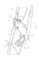
図1は、本実施の形態の解体仕様車100の外観を示す図である。解体仕様車100は、車両本体1と、作業機2とを有する。
Hereinafter, the dismantled specification vehicle provided with the working machine according to the embodiment of the present invention will be described with reference to the drawings.
<1. Configuration>
(1-1. Overview of dismantled vehicle)
FIG. 1 is a diagram showing the appearance of the disassembled
車両本体1は、走行体3と、旋回体4とを有する。走行体3は、一対の履帯3aを有しており、エンジンからの駆動力によって履帯3aが駆動されることによって解体仕様車100が走行する。
旋回体4は、走行体3上に旋回可能に載置されている。旋回体4は、キャブ5と、収納室6と、カウンタウェイト7等を有する。運転室としてのキャブ5は、旋回体4の前部左側位置に設けられている。収納室6は、キャブ5の後側に設けられており、エンジン、ラジエータおよびラジエータファン等を収納する。カウンタウェイト7は、旋回体4の後方に配置されている。
The vehicle body 1 has a traveling
The swivel body 4 is mounted on the traveling
(1−2.作業機)
作業機2は、メインブーム8と、メインブームシリンダ9と、第1アタッチメント10と、取付部30と、を有する。作業機2は、旋回体4の前部中央位置に取り付けられており、メインブーム8の基端部は、旋回体4に回動可能に連結されている。メインブーム8の先端部に第1アタッチメント10が着脱可能に取り付けられている。
(1-2. Working machine)
The working
メインブームシリンダ9は、ロッドの端がメインブーム8に接続され、シリンダチューブの端が旋回体4に接続されており、伸縮によりメインブーム8を起伏させる。
第1アタッチメント10は、第2ブーム11と、アーム12と、圧砕具13と、第1油圧シリンダ14と、第2油圧シリンダ15と、第3油圧シリンダ16とを有している。
第2ブーム11は、中間ブラケット17と、第2ブーム本体18とを有している。中間ブラケット17は、第2ブーム本体18の基端部53に取り付けられている。中間ブラケット17は、取付部30において、メインブーム8に着脱可能に取り付けられている。第1油圧シリンダ14は、ロッドの端が第2ブーム本体18に接続されており、シリンダチューブの端が中間ブラケット17に接続されている。
In the
The
The
アーム12は、第2ブーム11の先端に回動可能に取り付けられている。第2油圧シリンダ15は、ロッドの端がアーム12に接続されており、シリンダチューブの端が第2ブーム本体18に接続されている。
圧砕具13は、アーム12の先端に回動可能に取り付けられている。第3油圧シリンダ16は、ロッドの端が圧砕具13に接続されており、シリンダチューブの端がアーム12に接続されている。
The
The
メインブームシリンダ9、第1油圧シリンダ14、第2油圧シリンダ15、第3油圧シリンダ16が伸縮することによって作業機2が駆動される。
取付部30は、詳しくは後述するが、メインブーム8に中間ブラケット17を取り付ける。
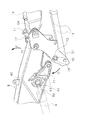
図2は、図1とは異なるアタッチメントを有する作業機2を備えた解体仕様車100の外観を示す図である。
The
Although the mounting
FIG. 2 is a diagram showing the appearance of a dismantling
図2に示す解体仕様車100の作業機2は、メインブーム8と、メインブームシリンダ9と、第2アタッチメント20と、を有する。
すなわち、図1に示す作業機2と図2に示す作業機2では、メインブーム8およびメインブームシリンダ9が共通である。
第2アタッチメント20は、第2ブーム21と、アーム22と、圧砕具23と、第1油圧シリンダ24と、第2油圧シリンダ25と、第3油圧シリンダ26と、中間リンク27と、を有している。
The
That is, the
The
第2ブーム21の基端部は、取付部30において、メインブーム8に着脱可能に取り付けられている。
中間リンク27は、第2ブーム21の先端に回動可能に取り付けられている。第1油圧シリンダ24は、ロッドの端が中間リンク27に接続されており、シリンダチューブの端が第2ブーム21に接続されている。
The base end portion of the
The
アーム22の基端部は、中間リンク27に回動可能に取り付けられている。第2油圧シリンダ25は、ロッドの端がアーム22に接続されており、シリンダチューブの端が中間リンク27に接続されている。
圧砕具23は、アーム22の先端に回動可能に取り付けられている。第3油圧シリンダ26は、ロッドの端が圧砕具23に接続されており、シリンダチューブの端がアーム22に接続されている。
The base end portion of the arm 22 is rotatably attached to the
The
取付部30は、第2ブーム21をメインブーム8に取り付ける。
メインブームシリンダ9、第1油圧シリンダ24、第2油圧シリンダ25、第3油圧シリンダ26が伸縮することによって作業機2が駆動される。
(1−3.取付部近傍の構成)
図3は、図1に示す取付部30近傍の構成を示す斜視図である。図4は、メインブーム8から第2ブーム11を取外した状態を示す斜視図である。なお、以下の説明において、作業機内側と記載した場合は、例えば図1に示すように作業機2を屈曲させた場合における作業機2の中心側を示す。また、作業機内側は、図3のようにメインブーム8を伏せて第2ブーム11を略水平に配置した状態では、下側に相当する。また、以下の明細書で作業機外側と記載した場合は、図1に示すような作業機2を屈曲させた場合における作業機2の外周側を示す。また、作業機外側は、図3のようにメインブーム8を伏せて第2ブーム11を略水平に配置した状態では、上側に相当する。図3では、作業機内側および作業機外側が、それぞれ矢印X1および矢印X2で示されている。
The mounting
The
(1-3. Configuration near the mounting part)
FIG. 3 is a perspective view showing a configuration in the vicinity of the mounting
メインブーム8は、メインブーム本体40と、ブラケット41とを有する。メインブーム本体40は、旋回体4に回動可能に取り付けられる基端部(図示せず)と、第2ブーム11が着脱可能に取り付けられる先端部42と、メインブームシリンダ9のロッド9aの先端が接続される接続部43とを有する。接続部43は、メインブーム本体40の幅方向Yの両側の側面40aに設けられている。すなわち、メインブームシリンダ9は、メインブーム8の幅方向Yの両側に配置されている。
The
ブラケット41は、接続部43よりも先端部42側であって、幅方向Yの両側の側面40aに設けられている。ブラケット41は、その根元部411で側面40aに固定されており、根元部411は、接続部43の先端部42側の近傍に配置されている。ブラケット41は、根元部411から先端部42側に向かってメインブーム本体40に沿って伸びている。ブラケット41の先端部42側の先端部412は、メインブーム本体40の側面40aから所定の空間を空けて配置されている。この先端部412と側面40aとの間の空間に、後述するブラケット部材51が挿入されている。
The
上述したように、中間ブラケット17は、第2ブーム本体18に取り付けられている。中間ブラケット17は、一対の板状のブラケット部材51と、一対のブラケット部材51を繋ぐ板状の接続部材52とを有する。一対のブラケット部材51は、第2ブーム本体18の基端部53を幅方向Yから挟むように、第2ブーム連結部54において、基端部53に回転可能に取り付けられている。
As described above, the
また、第1油圧シリンダ14は、幅方向Yに2本並んで配置されており、各々のブラケット部材51に、第2ブーム本体18よりも作業機内側(矢印X1)において回転可能に接続されている。第1油圧シリンダ14は、図3に示すように、ピストンロッド14aとシリンダチューブ14bとを有している。シリンダチューブ14bの端から幅方向Yの外側に向かって水平にシリンダ連結軸14cが突出しており、シリンダ連結軸14cがブラケット部材51に回転可能に支持されている。
Further, two first
(1−4.取付部)
次に、メインブーム8に第2ブーム11を取り付ける取付部30について説明する。取付部30は、図3に示すように、保持部31と、連結部32とを有しており、メインブーム8と第2ブーム11を保持部31で保持し、連結部32で連結することにより、メインブーム8に第2ブーム11を固定する。
(1-4. Mounting part)
Next, the mounting
保持部31は、作業機外側(矢印X2側)において、メインブーム8に第2ブーム11を係合して保持し、連結部32は、作業機内側(矢印X1側)において、メインブーム8と第2ブーム11を連結する。
(1−4−1.保持部31)
保持部31は、図4に示すように、ピン61と、支持部62とを有する。
The holding
(1-4-1. Holding unit 31)
As shown in FIG. 4, the holding
ピン61は、一対のブラケット部材51の間に幅方向Yに沿って配置されている。ピン61の両端の各々は、ブラケット部材51に固定されている。
支持部62は、メインブーム本体40の先端部42の作業機外側(矢印X2側)の端に幅方向Yに沿って形成されている。支持部62は、幅方向Yに沿って切り欠き部62aが形成された円筒形状であって、その内側に、幅方向Yに沿って軸を有する円柱状の空間を形成する。
The
The
ピン61は、切り欠き部62aを通過可能であり、切り欠き部62aを介して支持部62内に挿入されることによって支持部62によって支持される(矢印E参照)。なお、後述する連結部32においてメインブーム8と第2ブーム11が連結されていない状態では、ピン61は支持部62内において回動可能である。
(1−4−2.連結部32)
図5は、メインブーム8を伏せた状態を示す図であり、メインブーム8および第2ブーム11が略水平状態となっている。図6は、図5の状態におけるAA´間の矢示断面図である。
The
(1-4-2. Connecting part 32)
FIG. 5 is a diagram showing a state in which the
連結部32は、図6に示すように、主に、第1貫通孔71と、第2貫通孔72と、第1ブシュ73と、受け部材74と、第2ブシュ75と、油圧拡縮ピン76とを、幅方向Yの両側の各々に有する。
図7は、図6のB部拡大図である。図5〜図7に示すように、第1貫通孔71は、メインブーム8のブラケット41の先端部412に、幅方向Yに中心軸が沿うように形成されている。第2貫通孔72は、中間ブラケット17のブラケット部材51に、幅方向Yに中心軸が沿うように形成されている。
As shown in FIG. 6, the connecting portion 32 mainly includes a first through
FIG. 7 is an enlarged view of part B of FIG. As shown in FIGS. 5 to 7, the first through
第1ブシュ73は、円筒状の部材であって第1貫通孔71に配置されている。第1ブシュ73の幅方向Yの外側の端には、円筒の外周方向に形成された縁731が形成されており、ブラケット41の外表面41aの貫通孔71の周囲に形成された凹部内に配置されている。第1ブシュ73の幅方向Yの内側の端には、ブラケット41の内表面41bから突出した突出部732が設けられている。なお、ブラケット41の内表面41bは、ブラケット41のメインブーム本体40と対向する面である。ブラケット41の外表面41aは、ブラケット41の内表面41bの反対側の面であり、メインブーム本体40と対向しない面である。
The
図8は、メインブーム8を先端部42側から視た斜視図である。また、図8には、D部拡大図が示されている。
受け部材74は、第2ブーム11をメインブーム8に取り付ける際に、第1貫通孔71と第2貫通孔72の位置合わせを行うために設けられており、位置合わせの際に第2ブシュ75の一部が当接する。
FIG. 8 is a perspective view of the
The receiving
受け部材74は、図7および図8に示すように、幅方向Yの内側の面に段差が形成された円筒形状の部材であり、ブラケット41の先端部412の内表面41bに配置されている。図7および図8のD部拡大図に示すように、受け部材74は、上述した第1ブシュ73の突出部732の周囲に配置されている。
受け部材74は、円筒部741と、受け部742とを有する。円筒部741は、ブラケット41の内表面41bに接触し、図7に示すように、幅方向Yにおいて突出部732と略同じ長さである。受け部742は、円筒を2つの半径で区切った形状であり、円筒部741の幅方向Yの端面741aから突出するように形成されている。受け部742の幅方向Yの端面742aは、円筒部741の端面741aと平行に形成されている。
As shown in FIGS. 7 and 8, the receiving
The receiving
このように、受け部742は、第1貫通孔71の周囲の一部に形成されている。図9は、図6のCC´間の矢示断面図である。図9では、ブラケット41の内表面41bを見ており、図5と比較してブラケット41の上下方向が逆になっている。図9に示す受け部742は、図5に示すようなメインブーム8の状態において、円筒を直径で切った形状であり、メインブーム8の基端部側かつ作業機外側X2寄りに位置している。
As described above, the receiving
なお、図10(a)に示す受け部材74は、図10(b)に示すような部材174に貫通孔を形成することによって作成される。部材174は、一方の面174aに段差が形成されている円柱状の部材である。面174aは、他方の面174bからの距離が異なる2つの面174c、174dを有する。面174c、面174d、および面174bは互いに平行である。このような部材174に貫通孔を形成することにより、図10(a)に示すように円筒部741の貫通孔741cと受け部742の内周面742bとを同時に形成することができる。また、貫通孔741cの内周面741bと、受け部742の内周面742bは、同一面である。なお、図7に示すように、円筒部741の貫通孔741cは、第1貫通孔71と同じ半径である。
The receiving
なお、受け部742の形成箇所については、<2.取付動作>において更に後述する。
第2ブシュ75は、図7に示すように、円筒状の部材であって、ブラケット部材51に形成された第2貫通孔72に配置されている。ブラケット部材51の外表面51a(幅方向Yの外側)の第2貫通孔72の周囲には、円筒状の補助部材78が配置されている。また、ブラケット部材51の内表面51b(幅方向Yの内側)の第2貫通孔72の周囲には、円筒状の補助部材79が配置されている。これら補助部材78、79は、第2ブシュ75を保持するための面圧を確保するために設けられている。なお、ブラケット部材51の外表面51aは、メインブーム8のブラケット41の内表面41bに対向する面である。ブラケット部材51の内表面51bは、メインブーム本体40に対向する面である。
Regarding the formation location of the receiving
As shown in FIG. 7, the
第2ブシュ75の幅方向Yの内側の端には、円筒状の外周方向に形成された縁751が形成されており、補助部材79の幅方向Yの内側における面79aに形成された凹部内に配置されている。
図11は、図4に示す第2ブシュ75近傍の拡大図である。図7および図11に示すように、第2ブシュ75の幅方向Yの外側の端には、補助部材78の外側における面78aから突出した突出部752が設けられている。この突出部752が受け部742に当接した状態では、第1貫通孔71第2貫通孔72が対向して互いの中心が一致した状態となる。
At the inner end of the
FIG. 11 is an enlarged view of the vicinity of the
なお、補助部材78の面78aと、受け部742の端面742aの間には、隙間が形成されている。また、突出部752は、受け部材74の円筒部741には当接しないように形成されている。
油圧拡縮ピン76は、図6に示すように、幅方向Yに沿って配置されており、油圧によって、幅方向Yに伸縮する。油圧拡縮ピン76は、メインブーム本体40に幅方向Yに沿って配置されたピン支持部77(図6および図8参照)内に設けられている。
A gap is formed between the
As shown in FIG. 6, the hydraulic expansion /
油圧拡縮ピン76は、幅方向Yの両端に移動体761を有しており、油圧により2つの移動体761が幅方向Yの外側若しくは内側に向かって移動する。移動体761が内側に移動した状態では、後述する図16に示すように、油圧拡縮ピン76は、メインブーム本体40の内部に配置されている。
<2.取付動作>
図12は、本実施の形態の取付動作を示すフロー図である。
The hydraulic expansion /
<2. Mounting operation>
FIG. 12 is a flow chart showing the mounting operation of the present embodiment.
はじめに、ステップS10において、メインブーム8が伏せられた状態で、メインブーム8に第1アタッチメント10の第2ブーム11が保持部31において保持される。詳細には、第2ブームの中間ブラケット17のピン61が、切り欠き部62aを通して支持部62に配置される(図4の矢印E参照)。これによって図13に示すように、保持部31においてメインブーム8が第2ブーム11に保持される。
First, in step S10, the
次に、ステップS20において、メインブームシリンダ9が伸長され、メインブーム8が上方に向かって回動する(図12の矢印F参照)。このように、メインブーム8が上方に向かって回動すると、保持部31のピン61を回動支点として、第2ブーム11がメインブーム8側に向かって回動する(矢印G参照)。
次に、第2ブーム11のメインブーム8側への回動により、ステップS30において、図14Aおよび図14Bに示すように、第2ブシュ75の突出部752が、受け部材74の受け部742に当接する。この当接に伴いメインブームシリンダ9の伸長を停止させることにより、回動を停止させて、第1貫通孔71と第2貫通孔の位置合わせが完了する。図14Bは、図14Aのブラケット41および円筒部741を取り除いた状態を示す断面図である。
Next, in step S20, the
Next, by rotating the
図14Bに示すように、受け部742は、保持部31を中心として第2ブーム11が回動する回動方向(矢印G)側の第1貫通孔71の周囲に形成されている。
図15に示す模式側面図を用いて説明すると、ピン61の中心と第2貫通孔72の中心を結ぶ半径R1の円周C1上に第1貫通孔71の中心も配置されている。そして、円周C1に沿って第2ブシュ75は受け部742に接近する。そのため、本実施の形態では、第1貫通孔71の中心71aとピン61の中心を通る直線L1よりも第2ブーム11の回動方向(矢印G)側に受け部742(ハッチング部分)が形成されている。
As shown in FIG. 14B, the receiving
Explaining with reference to the schematic side view shown in FIG. 15, the center of the first through
図16は、ステップS30において、第1貫通孔71と第2貫通孔72の位置合わせが完了した状態における断面図であり、図16の断面図が示す部分は、図5のAA´間と同じ位置である。図16に示すように、位置合わせが完了した状態では、油圧拡縮ピン76は、縮小している状態である。この状態では、移動体761はメインブーム本体40の内側に入り込んでいる。
FIG. 16 is a cross-sectional view in a state where the alignment of the first through
次に、ステップS40において、油圧拡縮ピン76に油圧が供給され、移動体761は外側(矢印H参照)に移動する。これにより、図6に示すように第1貫通孔71および第2貫通孔72に挿入され、図3に示すように移動体761がブラケット41の外表面41aに現れ、メインブーム8への第2ブーム11の取付が完了する。
なお、第2アタッチメント20の場合は、第2ブーム21の基端部に、上述した中間ブラケット17と同様の構造が設けられている。具体的には、第2ブーム21の基端部にピン61が設けられ、第2ブーム21の両側面に第2貫通孔72、第2ブシュ75、および補助部材78、79が設けられている。そして、上記と同様にメインブーム8に第2ブーム21を取り付けることができる。
Next, in step S40, hydraulic pressure is supplied to the hydraulic expansion /
In the case of the
<3.特徴等>
(3−1)
本実施の形態の作業機2は、メインブーム8(第1ブームの一例)と、メインブーム8に着脱可能に取り付けられる第2ブーム11とを備えた作業機2であって、保持部31と、連結部32と、を備える。保持部31は、メインブーム8に第2ブーム11を保持する。連結部32は、メインブーム8と第2ブーム11を連結する。保持部31は、連結部32で連結されていない状態において、第2ブーム11をメインブーム8に対して回動可能に連結する。連結部32は、第1貫通孔71(第1ピン孔の一例)と、第2貫通孔72(第2ピン孔の一例)と、突出部752(第2突部の一例)と、受け部742(第1突部の一例)と、を有する。第1貫通孔71は、メインブーム8に形成されている。第2貫通孔72は、第2ブーム11に形成されている。受け部742は、保持部31を中心にして第2ブーム11をメインブーム8に向けて回動する回動方向(矢印G)側の第1貫通孔71の周囲に設けられている。突出部752は、第2貫通孔72の周囲に設けられている。受け部742に突出部752が当接した状態において、第1貫通孔71と第2貫通孔72が対向する。
<3. Features, etc.>
(3-1)
The working
ここで、図13に示すように、保持部31においてメインブーム8と第2ブーム11を係合して保持した状態で、例えば、メインブーム8を持ち上げると、第2ブーム11がメインブーム8側に向かって回動する。この回動により、突出部752が受け部742に当接すると、第1貫通孔71と第2貫通孔72が対向し第1貫通孔71と第2貫通孔72の位置合わせが完了した状態となる。そして、位置合わせが完了した第1貫通孔71と第2貫通孔72に油圧拡縮ピン76を挿入することにより、連結部32においてメインブーム8と第2ブーム11を連結することができる。このように、メインブーム8に第2ブーム11を保持部31で保持し連結部32において連結することにより、メインブーム8に第2ブーム11を固定することができる。
Here, as shown in FIG. 13, when the
以上のように、保持部31で保持した状態においてメインブーム8を持ち上げるだけで、メインブーム8に第2ブーム11を取り付けることが可能となり、ブーム間における取り付け作業を容易に行うことができる。
これにより、メインブーム8にアタッチメント10、20を容易に取り付けることができる。
As described above, the
As a result, the
(3−2)
本実施の形態の作業機2では、第2ブーム11は、第2ブーム本体18と、第2ブーム本体18の端に固定された中間ブラケット17(ブラケットの一例)と、を有する。第2貫通孔72(第2ピン孔の一例)および突出部752(第2突部の一例)は、中間ブラケット17に設けられている。
(3-2)
In the working
これによって、中間ブラケット17を有する第2ブーム11についても容易にメインブーム8に取り付けることができる。
(3−3)
本実施の形態の作業機2では、連結部32は、第1貫通孔71(第1ピン孔の一例)に対向する貫通孔741cを持ち、メインブーム8(第1ブームの一例)に配置された円筒部741を更に有する。受け部742(第1突部の一例)は、第1貫通孔71に沿って円筒部741から突出して形成されている。受け部742の第1貫通孔71に沿った内周面742bは、円筒部741の内周面741bと同一面である。受け部742と円筒部741は、一体的に構成されている。
As a result, the
(3-3)
In the working
これにより、1つの部材から受け部742と円筒部741を形成することが可能となり、第1貫通孔71に対して受け部742の位置を精度良く配置することができる。例えば、図10(a)、(b)に示すように、一つの部材174に対して1つの貫通孔を作成することにより円筒部741の貫通孔741cと受け部742の内周面742bとを同時に形成することができる。そのため、円筒部741の貫通孔741cの中心と第1貫通孔71の中心とを合わせるように円筒部741を配置することにより受け部742の内周面742bの中心も第1貫通孔71の中心と一致し、第1貫通孔71に対応して受け部742を精度良く配置することができる。
As a result, the receiving
(3−4)
本実施の形態の作業機2では、連結部32は、第1貫通孔71(第1ピン孔の一例)に配置された第1ブシュ73を有する。第1ブシュ73は、第1貫通孔71から幅方向Yに沿って突出した突出部732を持つ。貫通孔741cは、第1貫通孔71と同じ半径である。円筒部741は、突出部732の周囲に配置されている。
(3-4)
In the working
このように、第1貫通孔71に配置された第1ブシュ73の突出部732を基準に円筒部741を配置することができるため、円筒部741の中心が第1貫通孔71の中心に一致するように円筒部741を容易に配置することができる。
(3−5)
本実施の形態の作業機2では、保持部31は、ピン61(第1ピンの一例)と、支持部62(ピン支持部の一例)と、を有する。ピン61は、第2ブーム11に設けられている。支持部62は、連結部32でメインブーム8と第2ブーム11が連結されていない状態において、ピン61を回動可能に支持し、メインブーム8に設けられている。支持部62は、幅方向Yに沿って形成されピン61が通過可能な切り欠き部62aを持つ。
In this way, since the
(3-5)
In the working
これにより、切り欠き部62aを通してピン61を支持部62に配置することで、容易に第2ブーム11をメインブーム8に対して回動可能に連結することができる。
(3−6)
本実施の形態の作業機2では、突出部752(第2突部の一例)は、第2貫通孔72(第2ピン孔の一例)に配置された第2ブシュ75によって形成される。
Thereby, by arranging the
(3-6)
In the working
これにより、容易に第2貫通孔72に対する突出部752の位置も精度良く配置することが可能となり、第2ブシュ75が受け部742に当接することにより、第1貫通孔71と第2貫通孔72の位置合わせを行うことができる。
(3−7)
本実施の形態の作業機2は、メインブーム8(第1ブームの一例)と、メインブーム8に着脱可能に取り付けられる第2ブーム11とを備えた作業機2であって、保持部31と、連結部32と、を備える。保持部31は、メインブーム8と第2ブーム11を着脱可能に保持する。連結部32は、メインブーム8と第2ブーム11を着脱可能に連結する。保持部31は、連結部32で連結されていない状態において、第2ブーム11をメインブーム8に対して回動可能に連結する。連結部32は、第1貫通孔71(第1ピン孔の一例)と、第2貫通孔72(第2ピン孔の一例)と、油圧拡縮ピン76(第2ピンの一例)と、突出部752(第2突部の一例)と、受け部742(第1突部の一例)と、を有する。第1貫通孔71は、メインブーム8に形成されている。第2貫通孔72は、第2ブーム11に形成されている。油圧拡縮ピン76は、第1貫通孔71および第2貫通孔72に挿入される。受け部742は、保持部31を中心にして第2ブーム11をメインブーム8に向けて回動する回動方向(矢印G)側の第1貫通孔71の周囲に設けられている。突出部752は、第2貫通孔72の周囲に設けられている。受け部742に突出部752が当接した状態において、第1貫通孔71と第2貫通孔72が対向する。
As a result, the position of the protruding
(3-7)
The working
ここで、保持部31においてメインブーム8と第2ブーム11を連結した状態で、例えば、メインブーム8を持ち上げると、第2ブーム11がメインブーム8側に向かって回動する。この回動により、突出部752が受け部742に当接すると、第1貫通孔71と第2貫通孔72が対向し第1貫通孔71と第2貫通孔72の位置合わせが完了した状態となる。そして、位置合わせが完了した第1貫通孔71と第2貫通孔72に油圧拡縮ピン76を挿入することにより、連結部32においてメインブーム8と第2ブーム11を連結することができる。このように、メインブーム8に第2ブーム11を保持部31で保持し連結部32において連結することにより、メインブーム8に第2ブーム11を固定することができる。
Here, when the
(3−8)
第7の発明に係る取付方法は、メインブーム8(第1ブームの一例)に第2ブーム11を取り付ける取付方法であって、ステップS20(リフト工程の一例)、ステップS30(当接工程の一例)と、ステップS40(挿入工程の一例)と、を備える。ステップS20(リフト工程の一例)は、保持部31でメインブーム8と第2ブーム11を連結した状態において、メインブーム8の第2ブーム11側を持ち上げる。ステップS30(当接工程の一例)は、ステップS20(リフト工程の一例)によって第2ブーム11がメインブーム8に向かって回動し、メインブーム8に形成された第1貫通孔71(第1ピン孔の一例)の第2ブーム11の回動方向(矢印G)側の周囲に設けられた受け部742(第1突部の一例)に、第2ブーム11に形成された第2貫通孔72(第2ピン孔の一例)の周囲に設けられた突出部752(第2突部の一例)が当接し、第1貫通孔71と第2貫通孔72が対向した状態となる。ステップS40(挿入工程の一例)は、ステップS0(当接工程の一例)によって対向した状態となった第1貫通孔71と第2貫通孔72に油圧拡縮ピン76(第2ピンの一例)を挿入する。
(3-8)
The attachment method according to the seventh invention is an attachment method for attaching the
ここで、保持部31においてメインブーム8と第2ブーム11を連結した状態で、例えば、メインブーム8を持ち上げると、第2ブーム11がメインブーム8側に向かって回動する。この回動により、突出部752が受け部742に当接すると、第1貫通孔71と第2貫通孔72が対向し第1貫通孔71と第2貫通孔72の位置合わせが完了した状態となる。そして、位置合わせが完了した第1貫通孔71と第2貫通孔72に油圧拡縮ピン76を挿入することにより、油圧拡縮ピン76によってメインブーム8と第2ブーム11を連結することができる。このように、メインブーム8と第2ブーム11を2箇所で連結することにより、メインブーム8に第2ブーム11を固定することができる。
Here, when the
以上のように、保持部31で保持した状態においてメインブーム8を持ち上げるだけで、メインブーム8に第2ブーム11を取り付けることが可能となり、ブーム間における取り付け作業を容易に行うことができる。
これにより、メインブーム8にアタッチメントを容易に取り付けることができる。
[他の実施形態]
以上、本開示の一実施の形態について説明したが、本開示は上記実施の形態に限定されるものではなく、本開示の要旨を逸脱しない範囲で種々の変更が可能である。
As described above, the
As a result, the attachment can be easily attached to the
[Other Embodiments]
Although one embodiment of the present disclosure has been described above, the present disclosure is not limited to the above-described embodiment, and various changes can be made without departing from the gist of the present disclosure.
(A)
上記実施の形態では、図15において説明したように、第1貫通孔71の周囲であって第1貫通孔71とピン61とを結ぶ直線L1の回動方向(矢印G)側の領域の全体に受け部742が設けられているが、図17(a)に示す受け部842のように、全体に渡らなくてもよく一部であってもよい。また、受け部742は、周方向に連続していなくてもよく、図17(b)に示す受け部942のように間隔を空けて配置された複数の受け部分942aから形成されていてもよい。なお、受け部842、942は、説明のためにハッチングで示している。
(A)
In the above embodiment, as described with reference to FIG. 15, the entire region on the rotation direction (arrow G) side of the straight line L1 connecting the first through
また、受け部は、第1貫通孔71の周囲に沿って円周上に形成されていなくてもよく、単なる突起でもよい。
(B)
上記実施の形態では、受け部742に当接する突出部752として第2ブシュ75の全周が補助部材78から突出しているが、少なくとも受け部742に当接する部分が突出していればよい。
Further, the receiving portion may not be formed on the circumference along the circumference of the first through
(B)
In the above embodiment, the entire circumference of the
すなわち、図17(c)に示すように、ピン61の中心と第2貫通孔72の中心を結ぶ直線をL2とすると、突出部852(ハッチング部分参照)のように、第2貫通孔72の周囲であってL2よりも回動方向(矢印G)側の領域の少なくとも一部に設けられていればよい。
また、突出部752、852は、ブシュの一部によって形成されていなくてもよい。
That is, as shown in FIG. 17C, assuming that the straight line connecting the center of the
Further, the
(C)
上記実施の形態では、第1アタッチメント10および第2アタッチメント20の双方とも圧砕具13、23を有しているが、圧砕具13、23に限らずバケット等であってもよい。
(D)
上記実施の形態では、作業車両の一例として解体仕様車100を例に挙げて説明したが、解体仕様車に限らなくてもよく、複数のアタッチメントに交換可能な作業車両に適用することができる。
(C)
In the above embodiment, both the
(D)
In the above embodiment, the dismantling
本発明の作業車両は、ブーム間における取り付け作業を容易に行うことが可能な効果を有し、解体仕様車、油圧ショベルなどとして有用である。 The work vehicle of the present invention has an effect that the mounting work between booms can be easily performed, and is useful as a dismantling specification vehicle, a hydraulic excavator, and the like.
2 作業機
8 メインブーム
11 第2ブーム
31 保持部
32 連結部
71 第1貫通孔
72 第2貫通孔
76 油圧拡縮ピン
742 受け部
752 突出部
2 Working
Claims (7)
前記第1ブームに前記第2ブームを保持する保持部と、
前記第1ブームと前記第2ブームとを連結する連結部と、を備え、
前記保持部は、前記連結部で前記第1ブームと前記第2ブームが連結されていない状態において、前記第2ブームを前記第1ブームに対して回動可能に保持し、
前記連結部は、
前記第1ブームに形成された第1ピン孔と、
前記第2ブームに形成された第2ピン孔と、
前記保持部を中心にして前記第2ブームを前記第1ブームに向けて回動する回動方向側の前記第1ピン孔の周囲に沿って円周上の一部に形成された第1突部と、
前記第2ピン孔の周囲に設けられた第2突部と、を有し、
前記第1突部に前記第2突部が当接した状態において、前記第1ピン孔と前記第2ピン孔が対向する、
作業機。 A working machine including a first boom and a second boom that is detachably attached to the first boom.
A holding portion that holds the second boom in the first boom,
A connecting portion for connecting the first boom and the second boom is provided.
The holding portion rotatably holds the second boom with respect to the first boom in a state where the first boom and the second boom are not connected by the connecting portion.
The connecting part
The first pin hole formed in the first boom and
The second pin hole formed in the second boom and
A first protrusion formed on a part of the circumference along the circumference of the first pin hole on the rotation direction side in which the second boom rotates around the holding portion toward the first boom. Department and
It has a second protrusion provided around the second pin hole, and has.
In a state where the second protrusion is in contact with the first protrusion, the first pin hole and the second pin hole face each other.
Working machine.
第2ブーム本体と、
前記第2ブーム本体の端に固定されたブラケットと、を有し、
前記第2ピン孔および前記第2突部は、前記ブラケットに設けられている、
請求項1に記載の作業機。 The second boom is
The second boom body and
With a bracket fixed to the end of the second boom body,
The second pin hole and the second protrusion are provided on the bracket.
The working machine according to claim 1.
前記第1ピン孔に対向する貫通孔を持ち、前記第1ブームに配置された円筒部を更に有し、
前記第1突部は、前記第1ピン孔に沿って前記円筒部から突出して形成されており、
前記第1突部の前記第1ピン孔に沿った内周面は、前記貫通孔の内周面と同一面であり、
前記第1突部と前記円筒部は、一体的に構成されている、
請求項1に記載の作業機。 The connecting part
It has a through hole facing the first pin hole, and further has a cylindrical portion arranged in the first boom.
The first protrusion is formed so as to project from the cylindrical portion along the first pin hole.
The inner peripheral surface of the first protrusion along the first pin hole is the same surface as the inner peripheral surface of the through hole.
The first protrusion and the cylindrical portion are integrally formed.
The working machine according to claim 1.
前記第1ピン孔に配置された第1ブシュを有し、
前記第1ブシュは、前記第1ピン孔から幅方向に沿って突出した突出部を持ち、
前記貫通孔は、前記第1ピン孔と同じ半径であり
前記円筒部は、前記突出部の周囲に配置されている、
請求項3に記載の作業機。 The connecting part
It has a first bush located in the first pin hole and has a first bush.
The first bush has a protrusion protruding along the width direction from the first pin hole.
The through hole has the same radius as the first pin hole, and the cylindrical portion is arranged around the protruding portion.
The working machine according to claim 3.
幅方向に沿って前記第2ブームに設けられた第1ピンと、
前記連結部で前記第1ブームと前記第2ブームが連結されていない状態において前記第1ピンを回動可能に支持し、前記第1ブームに設けられたピン支持部と、
を有し、
前記ピン支持部は、幅方向に沿って形成され前記第1ピンが通過可能な切り欠き部を持つ、
請求項1に記載の作業機。 The holding part is
A first pin provided on the second boom along the width direction,
In a state where the first boom and the second boom are not connected by the connecting portion, the first pin is rotatably supported, and the pin supporting portion provided on the first boom
Have,
The pin support portion is formed along the width direction and has a notch portion through which the first pin can pass.
The working machine according to claim 1.
請求項1に記載の作業機。 The second protrusion is formed by a second bush arranged in the second pin hole.
The working machine according to claim 1.
前記第1ブームに前記第2ブームを着脱可能に保持する保持部と、
前記第1ブームと前記第2ブームとを着脱可能に連結する連結部と、を備え、
前記保持部は、前記連結部で前記第1ブームと前記第2ブームが連結されていない状態において、前記第2ブームを前記第1ブームに対して回動可能に保持し、
前記連結部は、
前記第1ブームに形成された第1ピン孔と、
前記第2ブームに形成された第2ピン孔と、
前記第1ピン孔および前記第2ピン孔に挿入された第2ピンと、
前記保持部を中心にして前記第2ブームを前記第1ブームに向けて回動する回動方向側の前記第1ピン孔の周囲に沿って円周上の一部に形成された第1突部と、
前記第2ピン孔の周囲に設けられた第2突部と、を有し、
前記第1突部に前記第2突部が当接した状態において、前記第1ピン孔と前記第2ピン孔が対向する、
作業機。 A working machine including a first boom and a second boom that is detachably attached to the first boom.
A holding portion that detachably holds the second boom on the first boom,
A connecting portion for detachably connecting the first boom and the second boom is provided.
The holding portion rotatably holds the second boom with respect to the first boom in a state where the first boom and the second boom are not connected by the connecting portion.
The connecting part
The first pin hole formed in the first boom and
The second pin hole formed in the second boom and
The first pin hole and the second pin inserted into the second pin hole,
A first protrusion formed on a part of the circumference along the circumference of the first pin hole on the rotation direction side in which the second boom rotates around the holding portion toward the first boom. Department and
It has a second protrusion provided around the second pin hole, and has.
In a state where the second protrusion is in contact with the first protrusion, the first pin hole and the second pin hole face each other.
Working machine.
Priority Applications (1)
| Application Number | Priority Date | Filing Date | Title |
|---|---|---|---|
| JP2016154969A JP6837775B2 (en) | 2016-08-05 | 2016-08-05 | Work machine |
Applications Claiming Priority (1)
| Application Number | Priority Date | Filing Date | Title |
|---|---|---|---|
| JP2016154969A JP6837775B2 (en) | 2016-08-05 | 2016-08-05 | Work machine |
Publications (2)
| Publication Number | Publication Date |
|---|---|
| JP2018021434A JP2018021434A (en) | 2018-02-08 |
| JP6837775B2 true JP6837775B2 (en) | 2021-03-03 |
Family
ID=61165284
Family Applications (1)
| Application Number | Title | Priority Date | Filing Date |
|---|---|---|---|
| JP2016154969A Active JP6837775B2 (en) | 2016-08-05 | 2016-08-05 | Work machine |
Country Status (1)
| Country | Link |
|---|---|
| JP (1) | JP6837775B2 (en) |
Families Citing this family (1)
| Publication number | Priority date | Publication date | Assignee | Title |
|---|---|---|---|---|
| JP7183598B2 (en) * | 2018-07-12 | 2022-12-06 | コベルコ建機株式会社 | work machine attachment |
Family Cites Families (5)
| Publication number | Priority date | Publication date | Assignee | Title |
|---|---|---|---|---|
| JPS59178454U (en) * | 1983-05-18 | 1984-11-29 | 新キャタピラ−三菱株式会社 | Boom connection device |
| JP4247222B2 (en) * | 2005-09-20 | 2009-04-02 | ヤンマー株式会社 | Excavator fixing structure of tractor loader backhoe |
| JP5035122B2 (en) * | 2008-06-04 | 2012-09-26 | コベルコ建機株式会社 | Boom assembly structure of work machine |
| JP5891716B2 (en) * | 2011-11-02 | 2016-03-23 | コベルコ建機株式会社 | Attachment of work machine |
| JP5842544B2 (en) * | 2011-11-04 | 2016-01-13 | コベルコ建機株式会社 | Work machine boom |
-
2016
- 2016-08-05 JP JP2016154969A patent/JP6837775B2/en active Active
Also Published As
| Publication number | Publication date |
|---|---|
| JP2018021434A (en) | 2018-02-08 |
Similar Documents
| Publication | Publication Date | Title |
|---|---|---|
| JP4566935B2 (en) | Excavator boom | |
| JP6837775B2 (en) | Work machine | |
| US8998560B2 (en) | Boom assembly | |
| JP6345538B2 (en) | Counterweight mounting device and combination thereof with counterweight | |
| JP4689252B2 (en) | Work machine blade device and work machine equipped with the same blade device | |
| CN204238272U (en) | Building machinery arm | |
| JP2007247143A (en) | Arm of excavating work machine | |
| CA2977586C (en) | Hoist drum for power shovel | |
| JP6260284B2 (en) | Construction machinery side frame | |
| JP7049855B2 (en) | How to move the bracket and front appliance | |
| JP7067223B2 (en) | Work machine equipped with a hanging tool at the connection part of the attachment | |
| JP5647886B2 (en) | Rotary work machine | |
| JP2015166513A (en) | Earth-removing device for construction machinery | |
| RU120430U1 (en) | ARROWS OF THE LAND LOADING MACHINE | |
| JP2005163375A (en) | Arm of construction machinery | |
| JP2013170582A (en) | Cylinder device | |
| CA3085203C (en) | Center pintle hub | |
| CN104812964A (en) | Boom assembly for construction machines | |
| JP6651220B2 (en) | Drilling machine attachment | |
| JP6908566B2 (en) | Soil removal equipment for construction machinery | |
| JP4292221B2 (en) | Swivel work machine | |
| WO2019130819A1 (en) | Arm for working machine, bearing member, and method for manufacturing arm for working machine | |
| JP6172172B2 (en) | Sensor mounting structure and work machine | |
| JPS6138019A (en) | Catch fork for pile driver | |
| JP2012225028A (en) | Spacer of construction machinery |
Legal Events
| Date | Code | Title | Description |
|---|---|---|---|
| A621 | Written request for application examination |
Free format text: JAPANESE INTERMEDIATE CODE: A621 Effective date: 20190701 |
|
| A977 | Report on retrieval |
Free format text: JAPANESE INTERMEDIATE CODE: A971007 Effective date: 20200605 |
|
| A131 | Notification of reasons for refusal |
Free format text: JAPANESE INTERMEDIATE CODE: A131 Effective date: 20200623 |
|
| A521 | Written amendment |
Free format text: JAPANESE INTERMEDIATE CODE: A523 Effective date: 20200821 |
|
| TRDD | Decision of grant or rejection written | ||
| A01 | Written decision to grant a patent or to grant a registration (utility model) |
Free format text: JAPANESE INTERMEDIATE CODE: A01 Effective date: 20210126 |
|
| A61 | First payment of annual fees (during grant procedure) |
Free format text: JAPANESE INTERMEDIATE CODE: A61 Effective date: 20210210 |
|
| R150 | Certificate of patent or registration of utility model |
Ref document number: 6837775 Country of ref document: JP Free format text: JAPANESE INTERMEDIATE CODE: R150 |