JP6836601B2 - Methods and equipment for plasma processing of containers - Google Patents
Methods and equipment for plasma processing of containers Download PDFInfo
- Publication number
- JP6836601B2 JP6836601B2 JP2018549488A JP2018549488A JP6836601B2 JP 6836601 B2 JP6836601 B2 JP 6836601B2 JP 2018549488 A JP2018549488 A JP 2018549488A JP 2018549488 A JP2018549488 A JP 2018549488A JP 6836601 B2 JP6836601 B2 JP 6836601B2
- Authority
- JP
- Japan
- Prior art keywords
- plasma
- process gas
- container
- malfunction
- station
- Prior art date
- Legal status (The legal status is an assumption and is not a legal conclusion. Google has not performed a legal analysis and makes no representation as to the accuracy of the status listed.)
- Active
Links
- 238000000034 method Methods 0.000 title claims description 136
- 238000012545 processing Methods 0.000 title claims description 54
- 230000008569 process Effects 0.000 claims description 113
- 230000007257 malfunction Effects 0.000 claims description 44
- 238000000576 coating method Methods 0.000 claims description 20
- 239000011248 coating agent Substances 0.000 claims description 15
- 238000009832 plasma treatment Methods 0.000 claims description 8
- 238000009423 ventilation Methods 0.000 claims description 8
- 239000012530 fluid Substances 0.000 claims description 3
- 230000000903 blocking effect Effects 0.000 claims description 2
- 230000001105 regulatory effect Effects 0.000 claims description 2
- 230000003796 beauty Effects 0.000 claims 1
- 238000005086 pumping Methods 0.000 claims 1
- 239000007789 gas Substances 0.000 description 115
- NJPPVKZQTLUDBO-UHFFFAOYSA-N novaluron Chemical group C1=C(Cl)C(OC(F)(F)C(OC(F)(F)F)F)=CC=C1NC(=O)NC(=O)C1=C(F)C=CC=C1F NJPPVKZQTLUDBO-UHFFFAOYSA-N 0.000 description 12
- 238000012546 transfer Methods 0.000 description 6
- 230000004888 barrier function Effects 0.000 description 5
- 239000007788 liquid Substances 0.000 description 5
- CURLTUGMZLYLDI-UHFFFAOYSA-N Carbon dioxide Chemical compound O=C=O CURLTUGMZLYLDI-UHFFFAOYSA-N 0.000 description 4
- VYPSYNLAJGMNEJ-UHFFFAOYSA-N Silicium dioxide Chemical compound O=[Si]=O VYPSYNLAJGMNEJ-UHFFFAOYSA-N 0.000 description 4
- 230000002950 deficient Effects 0.000 description 4
- 239000000047 product Substances 0.000 description 4
- 230000007547 defect Effects 0.000 description 3
- 238000010586 diagram Methods 0.000 description 3
- 239000000203 mixture Substances 0.000 description 3
- 230000004048 modification Effects 0.000 description 3
- 238000012986 modification Methods 0.000 description 3
- 229910052814 silicon oxide Inorganic materials 0.000 description 3
- 229910002092 carbon dioxide Inorganic materials 0.000 description 2
- 239000001569 carbon dioxide Substances 0.000 description 2
- 230000006870 function Effects 0.000 description 2
- 239000004033 plastic Substances 0.000 description 2
- 229920003023 plastic Polymers 0.000 description 2
- 230000002829 reductive effect Effects 0.000 description 2
- 230000008439 repair process Effects 0.000 description 2
- 238000007789 sealing Methods 0.000 description 2
- 238000011144 upstream manufacturing Methods 0.000 description 2
- 230000004913 activation Effects 0.000 description 1
- 230000002411 adverse Effects 0.000 description 1
- 238000005273 aeration Methods 0.000 description 1
- QVGXLLKOCUKJST-UHFFFAOYSA-N atomic oxygen Chemical compound [O] QVGXLLKOCUKJST-UHFFFAOYSA-N 0.000 description 1
- 230000008901 benefit Effects 0.000 description 1
- 239000011230 binding agent Substances 0.000 description 1
- 230000008859 change Effects 0.000 description 1
- 239000004020 conductor Substances 0.000 description 1
- 230000008878 coupling Effects 0.000 description 1
- 238000010168 coupling process Methods 0.000 description 1
- 238000005859 coupling reaction Methods 0.000 description 1
- 238000006073 displacement reaction Methods 0.000 description 1
- 230000014509 gene expression Effects 0.000 description 1
- 239000011521 glass Substances 0.000 description 1
- 230000002779 inactivation Effects 0.000 description 1
- 238000003780 insertion Methods 0.000 description 1
- 230000037431 insertion Effects 0.000 description 1
- 238000007689 inspection Methods 0.000 description 1
- 230000000670 limiting effect Effects 0.000 description 1
- 239000012263 liquid product Substances 0.000 description 1
- 230000007774 longterm Effects 0.000 description 1
- 238000004519 manufacturing process Methods 0.000 description 1
- 239000002184 metal Substances 0.000 description 1
- 231100000989 no adverse effect Toxicity 0.000 description 1
- 229910052760 oxygen Inorganic materials 0.000 description 1
- 239000001301 oxygen Substances 0.000 description 1
- 238000004806 packaging method and process Methods 0.000 description 1
- 230000036961 partial effect Effects 0.000 description 1
- 239000011253 protective coating Substances 0.000 description 1
- 125000006850 spacer group Chemical group 0.000 description 1
- 230000001954 sterilising effect Effects 0.000 description 1
- 238000004659 sterilization and disinfection Methods 0.000 description 1
- 239000012815 thermoplastic material Substances 0.000 description 1
- 230000007704 transition Effects 0.000 description 1
Images
Classifications
-
- C—CHEMISTRY; METALLURGY
- C23—COATING METALLIC MATERIAL; COATING MATERIAL WITH METALLIC MATERIAL; CHEMICAL SURFACE TREATMENT; DIFFUSION TREATMENT OF METALLIC MATERIAL; COATING BY VACUUM EVAPORATION, BY SPUTTERING, BY ION IMPLANTATION OR BY CHEMICAL VAPOUR DEPOSITION, IN GENERAL; INHIBITING CORROSION OF METALLIC MATERIAL OR INCRUSTATION IN GENERAL
- C23C—COATING METALLIC MATERIAL; COATING MATERIAL WITH METALLIC MATERIAL; SURFACE TREATMENT OF METALLIC MATERIAL BY DIFFUSION INTO THE SURFACE, BY CHEMICAL CONVERSION OR SUBSTITUTION; COATING BY VACUUM EVAPORATION, BY SPUTTERING, BY ION IMPLANTATION OR BY CHEMICAL VAPOUR DEPOSITION, IN GENERAL
- C23C16/00—Chemical coating by decomposition of gaseous compounds, without leaving reaction products of surface material in the coating, i.e. chemical vapour deposition [CVD] processes
- C23C16/04—Coating on selected surface areas, e.g. using masks
- C23C16/045—Coating cavities or hollow spaces, e.g. interior of tubes; Infiltration of porous substrates
-
- C—CHEMISTRY; METALLURGY
- C23—COATING METALLIC MATERIAL; COATING MATERIAL WITH METALLIC MATERIAL; CHEMICAL SURFACE TREATMENT; DIFFUSION TREATMENT OF METALLIC MATERIAL; COATING BY VACUUM EVAPORATION, BY SPUTTERING, BY ION IMPLANTATION OR BY CHEMICAL VAPOUR DEPOSITION, IN GENERAL; INHIBITING CORROSION OF METALLIC MATERIAL OR INCRUSTATION IN GENERAL
- C23C—COATING METALLIC MATERIAL; COATING MATERIAL WITH METALLIC MATERIAL; SURFACE TREATMENT OF METALLIC MATERIAL BY DIFFUSION INTO THE SURFACE, BY CHEMICAL CONVERSION OR SUBSTITUTION; COATING BY VACUUM EVAPORATION, BY SPUTTERING, BY ION IMPLANTATION OR BY CHEMICAL VAPOUR DEPOSITION, IN GENERAL
- C23C16/00—Chemical coating by decomposition of gaseous compounds, without leaving reaction products of surface material in the coating, i.e. chemical vapour deposition [CVD] processes
- C23C16/44—Chemical coating by decomposition of gaseous compounds, without leaving reaction products of surface material in the coating, i.e. chemical vapour deposition [CVD] processes characterised by the method of coating
- C23C16/4412—Details relating to the exhausts, e.g. pumps, filters, scrubbers, particle traps
-
- C—CHEMISTRY; METALLURGY
- C23—COATING METALLIC MATERIAL; COATING MATERIAL WITH METALLIC MATERIAL; CHEMICAL SURFACE TREATMENT; DIFFUSION TREATMENT OF METALLIC MATERIAL; COATING BY VACUUM EVAPORATION, BY SPUTTERING, BY ION IMPLANTATION OR BY CHEMICAL VAPOUR DEPOSITION, IN GENERAL; INHIBITING CORROSION OF METALLIC MATERIAL OR INCRUSTATION IN GENERAL
- C23C—COATING METALLIC MATERIAL; COATING MATERIAL WITH METALLIC MATERIAL; SURFACE TREATMENT OF METALLIC MATERIAL BY DIFFUSION INTO THE SURFACE, BY CHEMICAL CONVERSION OR SUBSTITUTION; COATING BY VACUUM EVAPORATION, BY SPUTTERING, BY ION IMPLANTATION OR BY CHEMICAL VAPOUR DEPOSITION, IN GENERAL
- C23C16/00—Chemical coating by decomposition of gaseous compounds, without leaving reaction products of surface material in the coating, i.e. chemical vapour deposition [CVD] processes
- C23C16/44—Chemical coating by decomposition of gaseous compounds, without leaving reaction products of surface material in the coating, i.e. chemical vapour deposition [CVD] processes characterised by the method of coating
- C23C16/455—Chemical coating by decomposition of gaseous compounds, without leaving reaction products of surface material in the coating, i.e. chemical vapour deposition [CVD] processes characterised by the method of coating characterised by the method used for introducing gases into reaction chamber or for modifying gas flows in reaction chamber
- C23C16/45561—Gas plumbing upstream of the reaction chamber
-
- C—CHEMISTRY; METALLURGY
- C23—COATING METALLIC MATERIAL; COATING MATERIAL WITH METALLIC MATERIAL; CHEMICAL SURFACE TREATMENT; DIFFUSION TREATMENT OF METALLIC MATERIAL; COATING BY VACUUM EVAPORATION, BY SPUTTERING, BY ION IMPLANTATION OR BY CHEMICAL VAPOUR DEPOSITION, IN GENERAL; INHIBITING CORROSION OF METALLIC MATERIAL OR INCRUSTATION IN GENERAL
- C23C—COATING METALLIC MATERIAL; COATING MATERIAL WITH METALLIC MATERIAL; SURFACE TREATMENT OF METALLIC MATERIAL BY DIFFUSION INTO THE SURFACE, BY CHEMICAL CONVERSION OR SUBSTITUTION; COATING BY VACUUM EVAPORATION, BY SPUTTERING, BY ION IMPLANTATION OR BY CHEMICAL VAPOUR DEPOSITION, IN GENERAL
- C23C16/00—Chemical coating by decomposition of gaseous compounds, without leaving reaction products of surface material in the coating, i.e. chemical vapour deposition [CVD] processes
- C23C16/44—Chemical coating by decomposition of gaseous compounds, without leaving reaction products of surface material in the coating, i.e. chemical vapour deposition [CVD] processes characterised by the method of coating
- C23C16/50—Chemical coating by decomposition of gaseous compounds, without leaving reaction products of surface material in the coating, i.e. chemical vapour deposition [CVD] processes characterised by the method of coating using electric discharges
- C23C16/511—Chemical coating by decomposition of gaseous compounds, without leaving reaction products of surface material in the coating, i.e. chemical vapour deposition [CVD] processes characterised by the method of coating using electric discharges using microwave discharges
-
- C—CHEMISTRY; METALLURGY
- C23—COATING METALLIC MATERIAL; COATING MATERIAL WITH METALLIC MATERIAL; CHEMICAL SURFACE TREATMENT; DIFFUSION TREATMENT OF METALLIC MATERIAL; COATING BY VACUUM EVAPORATION, BY SPUTTERING, BY ION IMPLANTATION OR BY CHEMICAL VAPOUR DEPOSITION, IN GENERAL; INHIBITING CORROSION OF METALLIC MATERIAL OR INCRUSTATION IN GENERAL
- C23C—COATING METALLIC MATERIAL; COATING MATERIAL WITH METALLIC MATERIAL; SURFACE TREATMENT OF METALLIC MATERIAL BY DIFFUSION INTO THE SURFACE, BY CHEMICAL CONVERSION OR SUBSTITUTION; COATING BY VACUUM EVAPORATION, BY SPUTTERING, BY ION IMPLANTATION OR BY CHEMICAL VAPOUR DEPOSITION, IN GENERAL
- C23C16/00—Chemical coating by decomposition of gaseous compounds, without leaving reaction products of surface material in the coating, i.e. chemical vapour deposition [CVD] processes
- C23C16/44—Chemical coating by decomposition of gaseous compounds, without leaving reaction products of surface material in the coating, i.e. chemical vapour deposition [CVD] processes characterised by the method of coating
- C23C16/52—Controlling or regulating the coating process
-
- C—CHEMISTRY; METALLURGY
- C23—COATING METALLIC MATERIAL; COATING MATERIAL WITH METALLIC MATERIAL; CHEMICAL SURFACE TREATMENT; DIFFUSION TREATMENT OF METALLIC MATERIAL; COATING BY VACUUM EVAPORATION, BY SPUTTERING, BY ION IMPLANTATION OR BY CHEMICAL VAPOUR DEPOSITION, IN GENERAL; INHIBITING CORROSION OF METALLIC MATERIAL OR INCRUSTATION IN GENERAL
- C23C—COATING METALLIC MATERIAL; COATING MATERIAL WITH METALLIC MATERIAL; SURFACE TREATMENT OF METALLIC MATERIAL BY DIFFUSION INTO THE SURFACE, BY CHEMICAL CONVERSION OR SUBSTITUTION; COATING BY VACUUM EVAPORATION, BY SPUTTERING, BY ION IMPLANTATION OR BY CHEMICAL VAPOUR DEPOSITION, IN GENERAL
- C23C16/00—Chemical coating by decomposition of gaseous compounds, without leaving reaction products of surface material in the coating, i.e. chemical vapour deposition [CVD] processes
- C23C16/44—Chemical coating by decomposition of gaseous compounds, without leaving reaction products of surface material in the coating, i.e. chemical vapour deposition [CVD] processes characterised by the method of coating
- C23C16/54—Apparatus specially adapted for continuous coating
-
- H—ELECTRICITY
- H01—ELECTRIC ELEMENTS
- H01J—ELECTRIC DISCHARGE TUBES OR DISCHARGE LAMPS
- H01J37/00—Discharge tubes with provision for introducing objects or material to be exposed to the discharge, e.g. for the purpose of examination or processing thereof
- H01J37/32—Gas-filled discharge tubes
- H01J37/32431—Constructional details of the reactor
- H01J37/3244—Gas supply means
- H01J37/32449—Gas control, e.g. control of the gas flow
-
- H—ELECTRICITY
- H01—ELECTRIC ELEMENTS
- H01J—ELECTRIC DISCHARGE TUBES OR DISCHARGE LAMPS
- H01J37/00—Discharge tubes with provision for introducing objects or material to be exposed to the discharge, e.g. for the purpose of examination or processing thereof
- H01J37/32—Gas-filled discharge tubes
- H01J37/32431—Constructional details of the reactor
- H01J37/32798—Further details of plasma apparatus not provided for in groups H01J37/3244 - H01J37/32788; special provisions for cleaning or maintenance of the apparatus
- H01J37/3288—Maintenance
-
- H—ELECTRICITY
- H01—ELECTRIC ELEMENTS
- H01J—ELECTRIC DISCHARGE TUBES OR DISCHARGE LAMPS
- H01J37/00—Discharge tubes with provision for introducing objects or material to be exposed to the discharge, e.g. for the purpose of examination or processing thereof
- H01J37/32—Gas-filled discharge tubes
- H01J37/32431—Constructional details of the reactor
- H01J37/32798—Further details of plasma apparatus not provided for in groups H01J37/3244 - H01J37/32788; special provisions for cleaning or maintenance of the apparatus
- H01J37/32899—Multiple chambers, e.g. cluster tools
-
- H—ELECTRICITY
- H01—ELECTRIC ELEMENTS
- H01J—ELECTRIC DISCHARGE TUBES OR DISCHARGE LAMPS
- H01J2237/00—Discharge tubes exposing object to beam, e.g. for analysis treatment, etching, imaging
- H01J2237/32—Processing objects by plasma generation
- H01J2237/33—Processing objects by plasma generation characterised by the type of processing
- H01J2237/332—Coating
- H01J2237/3321—CVD [Chemical Vapor Deposition]
-
- H—ELECTRICITY
- H01—ELECTRIC ELEMENTS
- H01J—ELECTRIC DISCHARGE TUBES OR DISCHARGE LAMPS
- H01J37/00—Discharge tubes with provision for introducing objects or material to be exposed to the discharge, e.g. for the purpose of examination or processing thereof
- H01J37/32—Gas-filled discharge tubes
- H01J37/32009—Arrangements for generation of plasma specially adapted for examination or treatment of objects, e.g. plasma sources
- H01J37/32192—Microwave generated discharge
- H01J37/32201—Generating means
Description
本発明は、請求項1のプリアンブルに記載の容器をプラズマ処理するための方法に関する。さらに、本発明は、請求項11のプリアンブルに記載の容器をプラズマ処理するための装置に関する。
The present invention relates to a method for plasma treating the container according to claim 1. Furthermore, the present invention relates to an apparatus for plasma-treating the container according to
そのような方法および装置は、例えば、プラスチックに表面コーティングを施すために使用される。特に、液体を詰めるための容器の内側表面または外側表面をコーティングするためのそのような装置も既に知られている。さらに、プラズマ滅菌するための装置も知られている。 Such methods and devices are used, for example, to apply a surface coating to plastics. In particular, such devices for coating the inner or outer surface of a container for filling liquids are already known. In addition, devices for plasma sterilization are also known.
公開された文献WO 95/22413 A1には、PETから作られる容器の内側をコーティングするためのプラズマチャンバーが記載されている。コーティングされる容器は、可動底によってプラズマチャンバー内に持ち上げられ、容器口部の領域でアダプタに結合する。アダプタを介して容器内部を排気できる。さらに、プロセスガスを供給するためにアダプタを介して容器内部に中空のガスランスが挿入される。マイクロ波を用いてプラズマ点火がなされる。 Published document WO 95/22413 A1 describes a plasma chamber for coating the inside of a container made from PET. The coated container is lifted into the plasma chamber by the movable bottom and coupled to the adapter in the area of the container mouth. The inside of the container can be exhausted via the adapter. Further, a hollow gas lance is inserted inside the container via an adapter to supply process gas. Plasma ignition is performed using microwaves.
この公開物から、複数のプラズマチャンバーを回転ホイール上に配置することも既知である。これにより、単位時間当たりの容器の高生産率が促進される。 From this publication, it is also known to place multiple plasma chambers on a rotating wheel. This promotes a high production rate of containers per unit time.
公開された文献EP 10 10 773 A1には、瓶内部を排気し、それにプロセスガスを供給するための供給装置が記載されている。WO 01/31680 A1には、瓶口部の領域と予め結合されている可動蓋によって、瓶が挿入されるプラズマチャンバーが記載されている。
Published
公開された文献WO 00/58631 A1にも、回転ホイール上にプラズマステーションを配置することが既に示され、チャンバーおよび瓶内部の好適な排気を促進するために、そのような配置に対して真空ステージおよびプラズマステーションをグループに分けて割り当てることが記載されている。共通のプラズマステーションまたは共通のチャンバーで複数の容器をコーティングすることも記載されている。 Published literature WO 00/58631 A1 has already shown that the plasma station is located on a rotating wheel, and a vacuum stage for such an arrangement to facilitate suitable exhaust inside the chamber and bottle. And the plasma stations are described as being divided into groups and assigned. It is also described to coat multiple vessels in a common plasma station or common chamber.
公開された文献WO 99/17334 A1には、瓶の内側をコーティングするための別の配置が説明されている。ここには、特に、プラズマチャンバー上方にマイクロ波発生器を配置し、プラズマチャンバーの底部を通る真空ラインおよび作用媒体供給ラインを配置することが記載されている。 Published literature WO 99/17334 A1 describes another arrangement for coating the inside of the bottle. In particular, it is described that a microwave generator is placed above the plasma chamber, and a vacuum line and a working medium supply line passing through the bottom of the plasma chamber are placed.
DE 10 2004 020 185 A1には、コーティングされるプリフォームの内部に挿入でき、プロセスガスを供給するために使用するガスランスが記載されている。容器の長手方向においてガスランスを位置決めできる。 DE 10 2004 020 185 A1 describes a gas lance that can be inserted inside a coated preform and used to supply process gas. The gas lance can be positioned in the longitudinal direction of the container.
知られている大多数の装置で、プラズマで生成される酸化ケイ素(一般式SiOx)の容器のコーティングが用いられ、熱可塑性材料のバリア性が改善される。特に容器の内壁上のそのようなバリアコーティングは、詰められた液体に酸素が侵入することを防止すると共に、二酸化炭素を含んだ液体の場合に二酸化炭素が漏れることを防止するので、容器に充填された液体および/または容器に詰められた液体の貯蔵性および/または長期にわたる貯蔵寿命を改善する。 In the majority of known devices, plasma-generated silicon oxide (general formula SiOx) container coatings are used to improve the barrier properties of thermoplastic materials. In particular, such a barrier coating on the inner wall of the container prevents oxygen from entering the packed liquid and also prevents carbon dioxide from leaking in the case of a liquid containing carbon dioxide, so that the container is filled. Improves the storability and / or long-term shelf life of liquids and / or liquids packed in containers.
プラズマ処理のための通常の装置構成では、n個の処理部がプラズマホイール上の対応する角度部分に配置され、各処理部は、1つ以上の排気可能なプラズマチャンバーを有するプラズマステーションを備え、今度はプラズマチャンバーが容器処理のための1つ以上の処理場所を有する。例えば、2または4個の処理場所が各プラズマチャンバーにまたはチャンバー内部に配置され、その結果、全体で2×nまたは4×n個の処理場所が上記装置形式のためのプラズマホイール上を循環する。 In a normal apparatus configuration for plasma processing, n processing units are arranged at corresponding angular portions on the plasma wheel, and each processing unit includes a plasma station having one or more exhaustable plasma chambers. The plasma chamber now has one or more treatment sites for container treatment. For example, 2 or 4 treatment sites are located in or inside each plasma chamber so that a total of 2 x n or 4 x n treatment sites circulate on the plasma wheel for the device type. ..
処理部のプラズマチャンバーが開放され、1つ以上の容器が載置または取出しステップでプラズマチャンバー内または外に一緒にガイドされる。これは、個々の容器に対して同時にまたはわずかに時間がずらされて実施され得る。プラズマステーションは、通常、載置または取出しステップで全容器がプラズマステーション内または外に一緒に同様にガイドされるように、処理部のユニットとして設けられる。従って、その最も簡易な構成において、処理部は、容器のための処理場所が配置されたチャンバー内部を備えるプラズマチャンバーを有するプラズマステーションを含む。 The plasma chamber of the processing unit is opened and one or more containers are guided together in or out of the plasma chamber in the loading or unloading step. This can be done simultaneously or slightly staggered for the individual containers. The plasma station is usually provided as a unit of processing so that all containers are similarly guided together in or out of the plasma station during the loading or unloading step. Thus, in its simplest configuration, the processing unit includes a plasma station having a plasma chamber with a chamber interior in which a processing site for the container is located.
プラズマ処理のための既知の方法および装置の場合、通常、対応するプラズマステーションのプラズマチャンバーに導入されるプロセスガスは、プラズマモジュールのホイール上に配置された全プラズマステーション(またはそれらの処理場所)と相互に作用する中央プロセスガス供給ユニットから供給される。 For known methods and equipment for plasma processing, the process gas introduced into the plasma chamber of the corresponding plasma station is typically with all plasma stations (or their processing location) located on the wheels of the plasma module. Supplied from an interacting central process gas supply unit.
従って、作動不良(即ち特に故障)がプラズマモジュールの1つ以上のプラズマステーションまたは処理場所で起こった場合、従来技術では、この対応するプラズマステーションに供給されたプロセスガスは、プラズマモジュールの残りの無損傷のプラズマステーションに分配される。これは、今度は、損傷していない残りのプラズマステーション、従って、どんな作動不良も被っていない残りのプラズマステーションにおける不必要なプロセスガスの処理量の増加をもたらし、従って、最終的に容器の内壁上のバリアコーティングの質に悪影響を与える。 Therefore, if a malfunction (ie, particularly failure) occurs at one or more plasma stations or processing sites of the plasma module, in the prior art, the process gas supplied to this corresponding plasma station will be the rest of the plasma module. Distribute to the damaged plasma station. This in turn results in an increase in the amount of unnecessary process gas processed in the remaining undamaged plasma station, and thus the remaining plasma station that has not suffered any malfunction, and thus ultimately the inner wall of the vessel. It adversely affects the quality of the above barrier coating.
本発明の目的は、作動不良(即ち特に故障)が少なくとも1つのプラズマステーションで起こった場合でさえ、残りの無損傷のプラズマステーションで容器の内壁上のバリアコーティングの一貫した質を提供する、容器をプラズマ処理するための方法および装置を提供することにある。 An object of the present invention is to provide a consistent quality of barrier coating on the inner wall of a vessel in the remaining intact plasma station, even if malfunction (ie particularly failure) occurs in at least one plasma station. To provide a method and an apparatus for plasma processing.
この目的を達成するために、請求項1に記載の製品をプラズマ処理するための方法が構成される。容器をプラズマ処理するための装置は請求項11の主題を形成する。
In order to achieve this object, a method for plasma treating the product according to claim 1 is configured. The apparatus for plasma treating the container forms the subject of
本発明の方法の本質的な面は、作動不良または遮断(即ち少なくとも1つの処理場所および/またはプラズマステーションの選択的な不活性化)の場合、プロセスガスは、処理場所および/またはプラズマステーションに供給される前に、バイパスラインによって運び去られるという事実を含む。本発明の方法は、1つ以上のプラズマステーションを有する複数の処理部をプラズマホイール上に備えるプラズマモジュールで実行される。プラズマモジュールにおいて、少なくとも部分的に排気されたプラズマチャンバー内で、特に少なくとも2つのプラズマステーションで同時に、1つ以上の容器内部にプロセスガスが少なくとも部分的に導入される。各プラズマステーションは各容器に対する少なくとも1つの処理場所を備える。従って、特に有利な方式において、欠陥を有する処理場所または欠陥を有するプラズマステーションで使用され得ないプロセスガスが、従来技術の通例のように、プラズマホイール上に配置された完全に機能する別のプラズマステーションに分配されるということはもはやない。本発明によれば、プロセスガスは、代わりに、遮断されているかまたは作動不良を有する処理場所および/またはプラズマステーションに供給される前に、1つ以上のバイパスラインによって運び去られまたは取り除かれる。結果として、欠陥を有するプラズマステーションに対して予め定められた量のプロセスガスは、残りのプラズマステーションまたは処理場所に分配されるのではなく運び去られるので、損傷しないで作動し、正常にコーティング工程と結びついた処理場所およびプラズマステーションにおけるプロセスガスの処理量の増加が防止される。 An essential aspect of the method of the invention is that in the event of malfunction or interruption (ie, selective inactivation of at least one treatment site and / or plasma station), the process gas will be delivered to the treatment site and / or plasma station. Includes the fact that it is carried away by the bypass line before it is supplied. The method of the present invention is performed on a plasma module having a plurality of processing units having one or more plasma stations on a plasma wheel. In the plasma module, the process gas is at least partially introduced into one or more vessels at the same time, at least in the partially exhausted plasma chamber, especially in at least two plasma stations. Each plasma station has at least one treatment site for each container. Thus, in a particularly advantageous scheme, the process gas that cannot be used in the defective treatment site or the defective plasma station is, as is customary in the prior art, another fully functional plasma placed on the plasma wheel. It is no longer distributed to stations. According to the present invention, the process gas is instead carried away or removed by one or more bypass lines before being fed to a treatment site and / or plasma station that is shut off or has a malfunction. As a result, a predetermined amount of process gas for the defective plasma station is carried away rather than distributed to the remaining plasma station or treatment site, so that it operates undamaged and the coating process is successful. The increase in the amount of process gas processed at the processing site and plasma station associated with is prevented.
プラズマステーションまたはその少なくとも1つの処理場所は、例えばそのプラズマステーションが欠陥または作動不良を有する場合、恒久的に遮断される。このようにして、プラズマステーションの修理または交換までの容器の不良率を低減できる。簡潔さのため、プラズマステーションの個々の処理場所だけが影響を受けていても、例えば遮断および作動不良がただ部分的だとしても、下記部分は、たいてい、プラズマステーション、遮断、および作動不良だけに言及する。この場合、本発明によれば、プラズマステーションまたはプラズマチャンバーのただ1つの処理場所または個々の処理場所が不活性化されるか、または、このために装置が設計および適合される。これは、以下の全ての説明および実施形態における本発明の方法および装置に対して常に類似に理解される。 The plasma station or at least one processing site thereof is permanently shut off, for example if the plasma station has a defect or malfunction. In this way, the defective rate of the container until the repair or replacement of the plasma station can be reduced. For brevity, even if only the individual processing locations of the plasma station are affected, for example if the shutoff and malfunction are only partial, the following parts are usually just the plasma station, shutoff, and malfunction. Mention. In this case, according to the present invention, only one treatment site or individual treatment site of the plasma station or plasma chamber is inactivated, or the device is designed and adapted for this purpose. This is always understood to be similar to the methods and devices of the invention in all the following description and embodiments.
また、始動で真空技術上の障害が生じる場合に、複数のプラズマステーションの1つが一時的に遮断される。真空の質が不適切である場合、設備が高速で稼働するならば、プラズマステーションから最初の瓶を除去する必要があるかもしれない。始動時に上流のプラズマステーションを選択的に自動で遮断することで、より良い真空を生成できる。これにより、コーティングされるまさに最初の容器に対して適切な真空の質が達成されるので、容器の除去が回避または少なくとも軽減され、不良率が低減される。 Also, one of the plurality of plasma stations is temporarily shut off in the event of a vacuum technical failure at start-up. If the vacuum quality is inadequate, it may be necessary to remove the first bottle from the plasma station if the equipment operates at high speed. A better vacuum can be generated by selectively and automatically shutting off the upstream plasma station at start-up. This achieves adequate vacuum quality for the very first container to be coated, thus avoiding or at least reducing container removal and reducing defect rates.
また、正しくない載置の場合、バイパスが活性化される。これは、プラズマステーションに容器がない状況、または容器がその設置場所に正しく保持されていない状況である。最後に、遮断およびバイパスの流れの活性化は、欠陥を整然と調査するように慎重に行われる。この選択肢は修理および点検のしやすさを改善する。また、以下で、用語「作動不良」は、常に、遮断されたプラズマステーションの一例を表すとみなされるべきである。なぜなら、完全な載置、およびプラズマホイールの全てのプラズマステーションの使用は、標準とみなされなければならず、制御された遮断さえもある種の作動不良に相当するからである。 Also, if the placement is incorrect, the bypass will be activated. This is a situation where the plasma station does not have a container, or the container is not properly held at its location. Finally, blocking and bypass flow activation is carefully performed to orderly investigate defects. This option improves ease of repair and inspection. Also, in the following, the term "malfunction" should always be considered as an example of a blocked plasma station. This is because full mounting and use of all plasma stations in the plasma wheel must be considered standard, and even controlled interruptions correspond to some sort of malfunction.
また、もちろん、本発明は、1つ以上のプラズマチャンバーが不活性化される場合に関し、即ち、プラズマチャンバーが遮断されまたは作動不良を有する全てのプラズマステーションに関する。 Also, of course, the present invention relates to the case where one or more plasma chambers are inactivated, that is, all plasma stations in which the plasma chambers are shut off or have malfunctions.
有利な実施形態において、作動不良を有する少なくとも1つのプラズマステーションにおいて、損傷しないで作動している場合のこのプラズマステーションに対して予め定められたプロセスガス量に対応する量のプロセスガスが運び去られ得る。 In an advantageous embodiment, in at least one plasma station with malfunction, an amount of process gas corresponding to a predetermined amount of process gas is carried away to the plasma station when operating undamaged. obtain.
別の有利な実施形態において、バイパスライン内のプロセスガスは、少なくとも1つの弁装置および/または絞り弁装置によって調整および/または制御されて運び去られ得る。 In another advantageous embodiment, the process gas in the bypass line can be tuned and / or controlled and carried away by at least one valve device and / or throttle valve device.
さらに別の有利な実施形態において、バイパスライン内の運び去られるプロセスガスの体積流量は、絞り弁装置によって調整および/または制御され得る。 In yet another advantageous embodiment, the volumetric flow rate of the process gas carried away in the bypass line can be regulated and / or controlled by a throttle valve device.
別の有利な実施形態において、作動不良を有する少なくとも1つのプラズマステーションのバイパスラインの絞り弁装置は、バイパスラインによって運び去られるプロセスガスの体積流量が、作動不良を有する少なくとも1つのプラズマステーションに向けて1つ以上の第1から第3弁装置によって加えられるプロセスガスの体積流量に対応するように、制御および/または調整され得る。 In another advantageous embodiment, the bypass line throttle valve device of at least one plasma station with malfunction directs the volumetric flow rate of the process gas carried away by the bypass line to at least one plasma station with malfunction. It can be controlled and / or adjusted to correspond to the volumetric flow rate of the process gas applied by one or more first to third valve devices.
有利に、作動不良を有する少なくとも1つプラズマチャンバーの1つ以上の第1から第3弁装置が開かれる時、上記弁装置は同時またはそれより少し前に開くことができ、プロセスガスはバイパスラインによって運び去られる。 Advantageously, when one or more of the first to third valve devices of at least one plasma chamber having a malfunction are opened, the valve devices can be opened simultaneously or shortly before, and the process gas is bypassed. Carried away by.
また、好適に、プロセスガスは、中央プロセスガス供給ユニットの1つ以上のプロセスガスラインによって、作動不良を有する少なくとも1つのプラズマステーションに向けて、所定のプロセスガス量でおよび/またはタイムシーケンスで供給され得る。 Also preferably, the process gas is supplied by one or more process gas lines of the central process gas supply unit to at least one plasma station with malfunction in a predetermined process gas amount and / or in a time sequence. Can be done.
さらに有利な実施形態において、作動不良を有する少なくとも1つのプラズマステーションのプロセスガスは、バイパスラインによって、中央真空装置に、好適には中央真空装置の最も低い真空レベルを有する真空ラインに、運び去られ得る。 In a more advantageous embodiment, the process gas of at least one plasma station with malfunction is carried away by the bypass line to the central vacuum system, preferably to the vacuum line with the lowest vacuum level of the central vacuum system. obtain.
本発明の目的のために、「作動不良」という用語は、非作動状態、即ち、例えば技術上の故障、特にプラズマステーションの技術上の故障と理解され、その結果、作動不良を有するプラズマステーションで容器をプラズマ処理することができない。 For the purposes of the present invention, the term "malfunction" is understood as a non-operating state, i.e., for example, a technical failure, in particular a technical failure of a plasma station, and as a result, in a plasma station having a malfunction. The container cannot be plasma treated.
本発明の目的のために、「容器」という用語は、特に、金属製、ガラス製および/またはプラスチック製の缶、瓶、樽、さらに子樽、管、小袋を包含するが、他の包装手段、特に、粉末状製品、顆粒状製品、液状製品、または、粘性を有する製品で満たされるのに適したものも包含する。 For the purposes of the present invention, the term "container" includes, among other things, metal, glass and / or plastic cans, bottles, barrels, as well as barrels, tubes, sachets, but other packaging means. In particular, those suitable for filling with powdered products, granular products, liquid products, or viscous products are also included.
本発明の目的のために、「本質的に」、「約」または「略」という表現は、正確な値からの±10%のずれ、好適には±5%のずれ、および/または、機能に重要ではない変化の形をとったずれを意味する。 For the purposes of the present invention, the expressions "essentially", "about" or "abbreviation" deviate ± 10% from the exact value, preferably ± 5%, and / or function. Means a shift in the form of a change that is not important to.
さらに別の本発明の実施形態、利点、および可能な適用は、下記の実施形態の記載および図面によって明らかにされる。記載されたおよび/または視覚的に表された全ての特質は、独立であろうと任意の所望の組合せであろうと、請求項またはその遡及適用の概要と無関係に、基本的に本発明の主題である。請求項の内容も明細書の必須部分である。 Yet another embodiment, advantage, and possible application of the present invention will be illustrated by the description and drawings of the embodiment below. All described and / or visually expressed qualities, whether independent or in any desired combination, are essentially in the subject matter of the invention, regardless of the claims or the outline of their retroactive application. is there. The content of the claims is also an essential part of the specification.
本発明は、図面を参照して実施例を用いて以下で詳細に説明される。 The present invention will be described in detail below with reference to the drawings and examples.
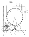
図1において、符号1は、回転プラズマホイール2を備えるプラズマモジュールを一般的に示す。プラズマホイール2の周に沿って、同一に構成された複数のプラズマステーション3が配置されている。プラズマステーション3は、処理される容器5を受け取るためのチャンバー内部4またはプラズマチャンバー17を備える。各容器は少なくとも1つの容器内部5.1を有する。
In FIG. 1, reference numeral 1 generally indicates a plasma module including a
処理される容器5は、装入部6の領域でプラズマモジュール1に供給され、その後、個別化ホイール7によって移送ホイール8に運ばれる。移送ホイール8は位置決め可能な担持アーム9を備えている。担持アーム9は、容器5相互の相対距離を変化させることができるように、移送ホイール8の台座10に対して相対的に回動可能に配置されている。結果として、個別化ホイール7と比較して容器5相互の相対距離を広くして、移送ホイール8から装入ホイール11に容器5を移送する。装入ホイール11は、処理される容器5をプラズマホイール2に移送する。処理が実施された後、処理された容器5は、搬出ホイール12によりプラズマホイール2の領域から除去されて、搬出部13の領域に移送される。
The
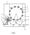
図2の実施形態において、各プラズマステーション3は2つの処理場所40および関連するチャンバー内部4またはプラズマチャンバー17を備えている。結果として、2つの容器5を一緒に同時に処理することができる。本質的に、チャンバー内部4を互いに完全に分離して構成することが可能であるが、本質的に、全ての容器5の最適なコーティングを保証するように、共通のチャンバー内部の一部を分離することも可能である。特に、別々のマイクロ波入射によって、チャンバー内部の一部を互いに分離することが提案される。
In the embodiment of FIG. 2, each
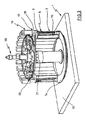
図3は、プラズマホイール2を部分的に組み立てたプラズマモジュール1の斜視図である。プラズマステーション3は運搬リング14上に配置されている。運搬リング14は、ロータリージョイントの一部として構成され、機械台座15の領域に取りつけられている。各プラズマステーション3は、プラズマチャンバー17を保持するステーションフレーム16を備える。
FIG. 3 is a perspective view of the plasma module 1 in which the
プラズマチャンバー17は筒形状のチャンバー壁18およびマイクロ波発生器19を備えることができる。
The
プラズマホイール2の中央に回転分配器20を設けることができる。回転分配器20によって、プラズマステーション3に、例えばプロセスガスのような作用媒体およびエネルギーが供給される。回転分配器20は、特に、中央プロセスガス供給ユニットと相互に作用できる。特に、作用媒体を分配するために、プラズマホイール2に環状本管21を備付けまたは配置することができる。
A
処理される容器5は筒形状のチャンバー壁18の下方に図示され、プラズマチャンバー17の下部は簡略化のために図示されていない。
The
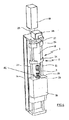
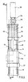
図4は、容器5のための処理場所40を有するプラズマステーション3の斜視図である。これから理解できるように、ステーションフレームはガイドロッド23を備え、筒形状のチャンバー壁18を保持するためのキャリッジ24はガイドロッド23上でガイドされている。図4に示すように、チャンバー壁18が設けられたキャリッジ24は、容器5が開放されるように持ち上げ状態にある。
FIG. 4 is a perspective view of the
マイクロ波発生器19はプラズマステーション3の上部領域に配置されている。マイクロ波発生器19は、デフレクタ25およびアダプタ26によって、プラズマチャンバー17に開口している連結チャネル27に接続されている。本質的に、チャンバーカバー31にマイクロ波発生器19を隣接させて配置できるか、または、チャンバーカバー31から予め定義できる距離離れた位置に、従ってチャンバーカバー31の周囲により広範囲に、スペーサ要素によってチャンバーカバー31にマイクロ波発生器19を連結させて配置できる。アダプタ26は遷移要素として機能し、連結チャネル27は同軸導体として構成されている。チャンバーカバー31に開口する連結チャネル27の開口領域には、石英ガラス窓が配置されている。デフレクタ25は導波管として構成されている。
The
容器5は、チャンバー床面29の領域に配置された保持要素28によって処理場所40に位置決めされる。チャンバー床面29はチャンバー台座30の一部として構成されている。調整を容易にするため、チャンバー台座30をガイドロッド23の領域に固定することができる。別の変形例では、チャンバー台座30がステーションフレーム16に直接固定される。そのような配置では、例えば、ガイドロッド23を鉛直方向において2つの部分に分けて実現することも可能である。
The
図5は、プラズマチャンバー17を密閉した状態における図3および図4のプラズマステーション3の正面図である。ここで、筒形状のチャンバー壁18が設けられたキャリッジ24は、チャンバー壁18がチャンバー床面29まで運ばれるように、図4の位置決めと比較して下げられている。この位置決め状態でプラズマコーティングを実施できる。
FIG. 5 is a front view of the
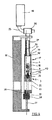
図6は図5の配置の鉛直断面図である。これから特に理解できるように、連結チャネル27はチャンバーカバー31に開口し、チャンバーカバー31は側方(横方向)に突出したフランジ32を備える。フランジ32の領域には、チャンバー壁18の内側フランジ34から圧力を受けるシール33が配置されている。これによって、チャンバー壁18が下げられた状態で、チャンバーカバー31に対するチャンバー壁18の密封がなされる。チャンバー壁18の下部領域には、ここでもチャンバー床面29に対する密封を保証するために、さらに別のシール35が配置されている。
FIG. 6 is a vertical cross-sectional view of the arrangement of FIG. As can be particularly understood from this, the connecting
図6に示す位置決めにおいて、チャンバー壁18は、チャンバー内部4および容器5の容器内部5.1の両方を排気できるように、チャンバー内部4を取り囲んでいる。プロセスガスの供給を促進するため、チャンバー台座30の領域には、容器5の容器内部5.1へ移動可能な中空のガスランス36が配置されている。ガスランス36の位置決めを容易にするため、ガスランス36は、ガイドロッド23に沿って位置決め可能なランスキャリッジ37に取付けられている。ランスキャリッジ37の内部には、図6に示す持ち上げ位置でチャンバー台座30のガス接続部39と連結されるプロセスガスチャネル38が延在している。この配置により、ランスキャリッジ37に管状結合要素を設ける必要がなくなる。ガスランス36が容器内部5.1に挿入された状態になると、容器5の容器内部5.1はチャンバー内部4から分離される(即ち密封される)。一方、ガスランス36が下げられた状態において、容器5の容器内部5.1とチャンバー内部4との間に、ガスを通すことができる接続が形成される。
In the positioning shown in FIG. 6, the
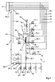
図7は、例として、上記実施形態の何れかのプラズマチャンバー17に1つ以上配置できるようなプラズマステーション3の処理場所40を示す概略ブロック図である。プラズマチャンバー17において、容器5は、ガスおよび/または空気に対して密閉されたチャンバー内部4に置かれ、位置決めされる。この例では、チャンバー台座30は真空チャネル70を備える。真空チャネル70は、その第1側70.1でプラズマチャンバー17に開口し、または、ガスランス36の位置次第で、容器5の容器内部5.1にガスを通すことができる接続も形成する。特に、ガスランス36が容器内部5.1に挿入された状態で、チャンバー内部4に対して容器内部5.1が分離される(即ち密封される)一方、ガスランス36が下げられた状態で、容器5の容器内部5.1とチャンバー内部4との間にガスを通すことができる接続が形成されることを提供できる。
FIG. 7 is a schematic block diagram showing a
また、少なくとも1つの第1から第5真空ライン71〜75および少なくとも1つの通気ライン76を真空チャネル70の第2側70.2に接続できる。通気ライン76は、特に、調整可能および/または制御可能な弁装置76.1によって活性化(アクティベート)および/または不活性化(ディアクティベート)されるように構成されている。さらに、第1から第5真空ライン71〜75のそれぞれも、少なくとも1つの調整可能および/または制御可能な弁装置71.1〜75.5を備えることができる。弁装置71.1〜76.1は、プラズマモジュール1の装置制御器(不図示)によって駆動可能に構成される。
Also, at least one first to fifth vacuum lines 71-75 and at least one
第1から第5真空ライン71〜75は、真空チャネル70の第2側70.2とは反対側の端で、好適に全ての真空ライン71〜75に共通の真空装置77に、流体気密に接続されている。真空装置77は、特にプラズマ処理中にプラズマチャンバー17および容器内部5.1に必要な真空を生成するように設計される。さらに、真空装置77は、第1から第5真空ライン71〜75に異なる真空、即ち、各真空ライン71〜75に対して異なる真空レベルを生成するように設計される。第5真空ライン75は、第1真空ライン71より良い真空度(即ち低い真空レベル)を有することが好ましい。特に、さらに第5真空ライン75が最も低い真空度を有するように、各真空ライン71〜75の真空レベルを低下させることが提案される。代わりに、個々の真空ライン71〜75のそれぞれを別々の真空装置77に接続することもできる。
The first to fifth vacuum lines 71-75 are at the end of the vacuum channel 70 opposite to the second side 70.2, and are preferably fluid-tightened to a
特に、第1から第5真空ライン71〜75によってプラズマチャンバー17内および/または容器内部5.1を異なる真空レベルまで低下させることを提案できる。これを達成できるのは、例えば、弁装置71.1が開かれると、第1真空ライン71によって、容器内部5.1を含めてプラズマチャンバー17内が第1真空レベルまで低下する一方、例えば、第2真空ライン72の弁装置72.1が開かれる場合、第1真空レベルより低い真空レベルがプラズマチャンバー17内および容器内部5.1の両方に生成されるからである。さらに、例えば、プラズマ処理中にプロセスガスを供給しながら同期して真空(真空度)を維持するために開かれるプロセス真空ラインとして、第5真空ライン75を構成することが提供されてもよい。このように、提供されたプロセス真空ラインは、抜き取られたプロセスガスが、他の真空ライン、例えば第1から第4真空ライン71〜74の供給周回路に移動することを防止する。
In particular, it can be proposed that the first to fifth vacuum lines 71-75 reduce the inside of the
また、例えば圧力測定管として構成され、第1から第5真空ライン71〜75によって生成される真空度を測定するように設計される圧力測定装置78を、第1から第5真空ライン71〜75に結合づけることができる。特に、上流弁装置78.1に圧力測定装置78を結合づけることができ、第2真空ライン72と真空チャネル70の第2側70.2との流体接続部に圧力測定装置78を配置できる。
Further, for example, a
さらに、例えば中央プロセスガスライン80によって、例えば第1から第3プロセスガスライン81〜83にガスランス36を接続できる。第1から第3プロセスガスライン81〜83のそれぞれを介して、ガスランス36によって、異なるプロセスガス組成物を特に容器内部5.1に供給できる。第1から第3プロセスガスライン81〜83のそれぞれは、例えばプラズマモジュール1の中央装置制御器によって調整可能および/または制御可能な少なくとも1つの弁装置81.1〜83.1をさらに備えることができる。従って、中央プロセスガスライン80も、同様の制御可能および/または調整可能な弁装置80.1を備えることができる。
Further, for example, the central
これに加えて、中央プロセスガスライン80の弁装置80.1と第1から第3プロセスガスライン81〜83の弁装置81.1〜83.1との間において、少なくとも1つのバイパスライン84が、その第1側84.1で流体気密に分岐し、その第2側84.2で同様に流体気密に第1から第5真空ライン71〜75の1つに開口していることが好ましい。バイパスライン84は、プラズマステーション3または処理場所40の作動不良の場合、第1から第3プロセスガスライン81〜83を流れるプロセスガスが、この少なくとも1つの作動不良の処理場所40のプラズマチャンバー17に供給される前に、有利に第1から第5真空ライン71〜75の1つに供給される前に運び去られるように構成される。特に有利な方式で、バイパスライン84は、その第2側84.2で、最も低い真空レベルを有する中央真空装置77の真空ラインに、即ち、図7に示された実施形態の第5真空ライン75に流体気密に開口している。代替の実施形態において、バイパスライン84は別々の真空装置(不図示)に流体気密に開口してもよい。
In addition, there is at least one
また、バイパスライン84は、プラズマモジュール1の中央装置制御器によって制御可能および/または調整可能な少なくとも1つの弁装置84.3と、バイパスライン84を流れるプロセスガスの流量調整または体積流量制限のための制御可能および/または調整可能な少なくとも1つの絞り弁装置84.4と、を備える。例えば、制御可能および/または可変な仕切弁として、従って、特にバイパスライン84を流れるプロセスガスの体積流量を制限するように、絞り弁装置84.4を構成できる。特に、絞り弁装置84.4は、バイパスライン84において、矢印で示された流れの方向に対して、弁装置84.3より下流に設けられる。
Further, the
特に有利に、バイパスライン84を介して運び去られるプロセスガスの体積流量が、プロセスガスの導入中の処理場所40に対応する中央プロセスガスラインを介して供給されるプロセスガスの体積流量に略等しくなるように、絞り弁装置84.4によって、バイパスライン84の内側の断面積を特定寸法にすることおよび/または設定することができる。換言すると、従って、バイパスライン84の内側の断面積は、プロセスガスが運び去られる間、バイパスライン84内の真空コンダクタンスがプラズマ処理のためのプロセスガスの導入中の中央プロセスガスライン80内のものと略等しくなるように、絞り弁装置84.4によって選択または設定される。
Particularly advantageously, the volumetric flow rate of the process gas carried away via the
さらに、第6真空ライン85は、第1側85.1で、プラズマチャンバー17に直接および特に流体気密に接続または開口でき、第2側85.2で、第5真空ライン75によって、可変および/または制御可能な弁装置85.3を介して、中央真空装置77と流体気密に相互に作用できる。特にプラズマチャンバー17内の真空度を測定するため、例えば圧力測定管として構成される圧力測定装置86に第6真空ライン85を結合づけることもできる。
In addition, the
以下で、コーティング工程の例を用いて、作動不良を有しない例示的な処理場所40で行われる典型的な処理工程を説明する。コーティング工程において、容器5のプラズマ処理のための方法は、各処理場所40を有する複数のプラズマステーション3をプラズマホイール2上に備えるプラズマモジュール1で実施される。
In the following, a typical treatment step performed at an
ここで、まず、装入ホイールを使用してプラズマホイール2に各容器5が搬送され、スリーブ状のチャンバー壁18が持ち上げられた状態で、対応する処理場所40に容器5が挿入される。挿入工程の完了時に、この処理場所40の各チャンバー壁18が密封位置まで下げられ、初めにチャンバー内部4および容器5の容器内部5.1の両方が同時に排気される。
Here, first, each
チャンバー内部4が十分に排気された後、対応するガスランス36が容器5の容器内部5.1に挿入され、シール要素28の変位によってチャンバー内部4に対して容器内部5.1が密封される。チャンバー内部4の排気開始に同期して容器5内にガスランス36をもう挿入することも可能である。その後、容器内部5.1の圧力をさらに低下させることができる。さらに、チャンバー壁18の位置決めに少なくとも部分的に並行してガスランス36の位置決め移動を実行することも可能である。
After the chamber interior 4 is sufficiently exhausted, the corresponding
十分に低い真空度が達成されると、対応する処理場所40で容器5の容器内部5.1にプロセスガスが導入され、マイクロ波発生器19を用いてプラズマ点火がなされる。特に、プラズマのおかげで、酸化ケイ素の接合剤、実際のバリア、および保護用コーティングが容器5の内側表面に形成されるような処理を提供できる。
When a sufficiently low degree of vacuum is achieved, the process gas is introduced into the container interior 5.1 of the
コーティング工程(即ちプラズマ処理)の完了時に、容器内部5.1からガスランス36が除去され(即ち下げられ)、ガスランス36が下げられることと同期してまたはその前に、少なくとも容器5の容器内部5.1が(必要ならばプラズマチャンバー17も)少なくとも部分的に通気される。
At the completion of the coating process (ie, plasma treatment), the
少なくとも1つの処理場所40が作動不良を被る場合、対応するプラズマチャンバー17に向けてプロセスガスが加えられまたは供給される時、作動不良を被るこの少なくとも1つの処理場所40のプロセスガスはバイパスライン84によって運び去られる。その結果、作動不良を有せず、プロセスガスの導入という同じ処理ステップをその時に受ける、プラズマモジュール1の少なくとも1つのさらに別の処理場所40において、中央プロセスガス供給ユニットによって供給されるプロセスガスの処理量(流量)が増加することはない。これは、作動不良を被る処理場所に対して予め定められた割合または量のプロセスガスがバイパスライン84によって運び去られるからである。従って、処理される容器5は所定量のプロセスガスを導入されるので、この少なくとも1つのさらに別の作動可能な処理場所40におけるプラズマコーティングの質に悪影響はない。作動不良を被る少なくとも1つの処理場所40に向かって流れるプロセスガスは、バイパスライン84によって運び去られるので、プラズマモジュール1に設けられた残りのプラズマステーション3またはそれらの処理場所40において、高いコーティングの質を一貫して維持してコーティング工程を実行および/または継続できる。
If at least one
初めに、プラズマチャンバー17が閉じられた後、損傷しないで作動している(即ちどんな作動不良も被っていない)少なくとも1つのプラズマチャンバー3において、例えば第1および第6弁装置71.1および85.1がそれぞれ開かれ、容器内部5.1およびプラズマチャンバー17の内部の両方がそれぞれ第1および第6真空ライン71および85を介して排気される。これが行われている間、中央プロセスガスライン80の弁装置80.1は閉じられていることが好ましい。特に、容器内部5.1およびプラズマチャンバー17の排気中、通気ライン76の弁装置76.1も閉じられている。第1弁装置71.1を閉じた後、例えば第2弁装置72.1を開くことができ、第2真空ライン72によって容器内部5.1をより低い圧力レベルまで低下させることができる。コーティング工程のために必要ならば、第3または第4真空ライン73,74によって、容器内部5.1および/またはプラズマチャンバー17内をより低い真空レベルまで次第に低下させることもできる。容器内部5.1および/またはプラズマチャンバー17内で十分に低い圧力レベルが達成されるとすぐに、対応する弁装置71.1〜75.1を閉じることができる。あるいは、後続の処理ステップにおいて容器内部5.1およびプラズマチャンバー17内で十分に低い圧力レベルを維持するために、特に第5弁装置75.1および第6弁装置85.3を開いたままにすることが提供されてもよい。
First, after the
ここで、少なくとも1つの正常に作動しているプラズマチャンバー3において、容器内部5.1へのガスランス36の位置決めと同時またはその前に、第1から第3プロセスガスライン81〜83の第1から第3弁装置81.1〜83.1の1つ以上、および中央プロセスガスライン80の弁装置80.1を開くことができ、ガスランス36を介して特に容器内部5.1に所定の組成および所定のガス量のプロセスガスを供給できる。
Here, in at least one normally operating
さらに、作動不良を有する少なくとも1つのプラズマチャンバー3において、第1から第3プロセスガスライン81〜83の第1から第3弁装置81.1〜83.1の1つ以上が、プラズマモジュール1に設けられた残りのプラズマチャンバー3に対する所定のタイムシーケンスに合わせて開かれる。一方、作動不良を有するこの1つの処理場所3の中央プロセスガスライン80の弁装置80.1は閉じられ、その結果として、プロセスガスは、対応するプラズマチャンバー17に流入できない。このため、作動不良を有する少なくとも1つの処理場所40に向けて、損傷しないで作動している場合のこの処理場所40に対して予め定められたプロセスガス量に対応する量のプロセスガスが供給される。
Further, in at least one
特に好適には、作動不良を有する少なくとも1つのプラズマステーション3の第1から第3プロセスガスライン81〜83の第1から第3弁装置80.1〜83.1の1つ以上が開くと同時またはそれより少し前に、弁装置84.3が開かれ、プロセスガスはバイパスライン84を介して運び去られる。
Particularly preferably, at the same time as one or more of the first to
特に、作動不良を有する少なくとも1つのプラズマステーション3において、バイパスライン84の弁装置84.3が開く時、中央プロセスガスライン80の弁装置80.4は、中央プロセスガス供給ユニットによって供給されるプロセスガスがバイパスライン84によって中央真空装置77に供給されるように閉じられる。プロセスガスは、特に、第5真空ライン75を介して排出される。プロセスガスは、特に、プラズマホイール2の中央に設けられた回転分配器20を介してプラズマステーション3または各処理場所40に供給され得るが、実際のプロセスガスの分配はリングライン21を介して達成され得る。
In particular, in at least one
プロセスガスが十分に供給された後、マイクロ波発生器19は容器5の容器内部5.1でプラズマ点火を行う。この状況において、例えば、予め定義できる時点で第1プロセスガスライン81の弁装置81.1は閉じるが、第2プロセスガスライン82の弁装置82.1が開かれ、第2の組成のプロセスガスが供給されることを提供できる。同時に、特に容器内部5.1および/またはプロセスチャンバー17内で十分に低い真空度を保つために、少なくとも一時的に、第5弁装置75.1および/または第6弁装置85.3を開くこともできる。ここで、略0.3ミリバールの圧力レベルが適切であるとわかっている。
After the process gas is sufficiently supplied, the
プラズマ処理の完了時、この時点でまだ開いている、第1から第3プロセスガスライン81〜83の弁装置81.1〜83.1、および第1から第6真空ライン71〜75,85の弁装置71.1〜75.1,85.3の全てが閉じられる。一方、プラズマステーション3の少なくとも1つの処理場所40でのプラズマ処理後、通気ライン76の弁装置76.1が開かれ、少なくとも容器5の容器内部5.1が少なくとも部分的に通気される。容器5の容器内部5.1は好適に大気圧まで通気される。
At the completion of the plasma treatment, the valve devices 81.1-83.1 of the first to third
通気は好適に容器内部5.1のガスランス36によって行われる。同時に容器内部5.1からガスランス36を下げることができる。容器内部5.1およびプラズマチャンバー17が、好適には大気圧または雰囲気圧まで十分に通気されたら、通気ライン76の開いている弁装置76.1が閉じられる。容器5毎の通気時間は、0.1秒から0.4秒までの間であり、好適には約0.2秒である。雰囲気圧がチャンバー内部4で達成されると、チャンバー壁18は再び持ち上げられる。それから、コーティングされた容器5は、取り出され、および/または搬出ホイール12に移される。
Ventilation is preferably performed by the
本発明は、実施形態を参照して上記のように説明された。本発明の基礎となる発明概念から外れることなく、多くの変形および修正が可能であることは言うまでもない。 The present invention has been described above with reference to embodiments. It goes without saying that many modifications and modifications can be made without departing from the invention concept underlying the present invention.
1…プラズマモジュール
2…プラズマホイール
3…プラズマステーション
4…チャンバー内部
5…容器
5.1…容器内部
6…装入部
7…個別化ホイール
8…移送ホイール
9…担持アーム
10…台座
11…装入ホイール
12…搬出ホイール
13…搬出部
14…運搬リング
15…機械台座
16…ステーションフレーム
17…プラズマチャンバー
18…チャンバー壁
19…マイクロ波発生器
20…回転分配器
21…環状本管
23…ガイドロッド
24…キャリッジ
25…デフレクタ
26…アダプタ
27…連結チャネル
28…保持要素
29…チャンバー床面
30…チャンバー台座
31…チャンバー台座
32…フランジ
33…シール
34…内側フランジ
35…シール
36…ガスランス
37…ランスキャリッジ
38…プロセスガスチャネル
39…ガス接続部
40…処理場所
70…真空チャネル
70.1…第1側
70.2…第2側
71…第1真空ライン
71.1…弁装置
72…第2真空ライン
72.1…弁装置
73…第3真空ライン
73.1…弁装置
74…第4真空ライン
74.1…弁装置
75…第5真空ライン
75.1…弁装置
76…通気ライン
76.1…弁装置
77…真空装置
78…圧力測定装置
78.1…弁装置
80…中央プロセスガスライン
80.1…弁装置
81…第1プロセスガスライン
81.1…弁装置
82…第2プロセスガスライン
82.2…弁装置
83…第3プロセスガスライン
83.1…弁装置
84…バイパスライン
84.1…第1側
84.2…第2側
84.3…弁装置
84.4…絞り弁装置
85…第6真空ライン
85.1…第1側
85.2…第2側
85.3…弁装置
86…圧力測定装置
1 ...
Claims (15)
容器内部(5.1)を有する少なくとも1つの容器(5)を、対応するプラズマステーション(3)の前記処理場所(40)にかかる前記プラズマチャンバー(17)内に挿入して位置決めするステップと、
前記各プラズマチャンバー(17)および前記少なくとも1つの容器内部(5.1)を少なくとも部分的に排気するステップと、
前記少なくとも部分的に排気されたプラズマチャンバー(17)内の前記容器内部(5.1)にプロセスガスを少なくとも部分的に導入するステップであって、中央プロセスガス供給部によって少なくとも1つのプラズマステーション(3)で同時に行われるステップと、
プラズマ処理によって少なくとも前記容器内部(5.1)に内部コーティングを施すステップと、
前記プラズマ処理後、前記プラズマチャンバー(17)および前記容器(5)の前記少なくとも1つの容器内部(5.1)の両方を少なくとも部分的に通気する通気工程を実行するステップと、を備え、
前記プラズマステーション(3)の1つの少なくとも1つの処理場所(40)が作動不良を有しおよび/または遮断された場合、前記プロセスガスは、少なくとも前記作動不良を有しおよび/または遮断された処理場所(40)および/またはそこに保持されている前記容器(5)に供給される前に、バイパスライン(84)によって、少なくとも部分的に、運び去られることを特徴とする、方法。 A method for plasma processing a container (5) by a plasma module (1) having a plurality of plasma stations (3) on a plasma wheel (2), and each plasma station (3) has at least one processing place (1). The method comprises at least one plasma chamber (17) having 40).
A step of inserting and positioning at least one container (5) having a container interior (5.1) into the plasma chamber (17) at the processing site (40) of the corresponding plasma station (3).
A step of at least partially exhausting each of the plasma chambers (17) and the inside of the at least one container (5.1).
A step of at least partially introducing process gas into the container (5.1) in the at least partially exhausted plasma chamber (17), at least one plasma station by a central process gas supply. Steps performed at the same time in 3) and
The step of applying an internal coating to at least the inside of the container (5.1) by plasma treatment, and
After the plasma treatment, a step of performing a ventilation step of at least partially ventilating both the inside of the plasma chamber (17) and the container (5) at least one of the containers (5.1) is provided.
If at least one treatment site (40) of the plasma station (3) is malfunctioning and / or shut off, the process gas is at least said malfunctioning and / or shut off. before being fed to the location (40) and / or the container there is held (5), by a bypass line (84), and wherein the at least partially be surround beauty method.
前記各プラズマステーション(3)は、前記プラズマステーション(3)の前記処理場所(40)の少なくとも1つが作動不良を有しおよび/または遮断された場合、前記プロセスガスが、前記作動不良および/または遮断が生じた前記プラズマチャンバー(17)および/または前記処理場所(40)に供給される前に、1つ以上のバイパスライン(84)によって運び去られ得るように、少なくとも1つのバイパスライン(84)を備えることを特徴とする装置。 A device for plasma processing a container (5), including a plurality of plasma stations (3) arranged on a plasma wheel (2), and each plasma station (3) has at least one processing place (40). At least one container (5) having the inside of the container (5.1) is inserted into the plasma chamber (17) at the processing site (40) and positioned. Each of the plasma chambers (17) is configured to be at least partially evacuated, and the plasma station (3) is at least two processing sites (40) at the same time in each of the containers ( The process gas is at least partially introduced into the inside (5.1) of the at least one container of 5), and the plasma station (3) is at least partially exhausted by plasma treatment. The inside of the container (5.1) in the plasma chamber (17) is also provided so as to apply an internal coating, and the plasma station (3) is the plasma chamber at the processing place (40) after the plasma treatment. (17) and at least one ventilation line (76) for at least partially ventilating both the inside of the at least one container (5.1).
In each of the plasma stations (3), if at least one of the processing sites (40) of the plasma station (3) has a malfunction and / or is shut off, the process gas will cause the malfunction and / or At least one bypass line (84) so that it can be carried away by one or more bypass lines (84) before being fed to the plasma chamber (17) and / or the treatment site (40) where the interruption occurred. ) Is provided.
Applications Claiming Priority (3)
| Application Number | Priority Date | Filing Date | Title |
|---|---|---|---|
| DE102016105548.4 | 2016-03-24 | ||
| DE102016105548.4A DE102016105548A1 (en) | 2016-03-24 | 2016-03-24 | Method and apparatus for plasma treatment of containers |
| PCT/EP2017/056223 WO2017162509A1 (en) | 2016-03-24 | 2017-03-16 | Method and device for plasma treatment of containers |
Publications (3)
| Publication Number | Publication Date |
|---|---|
| JP2019510881A JP2019510881A (en) | 2019-04-18 |
| JP2019510881A5 JP2019510881A5 (en) | 2020-03-12 |
| JP6836601B2 true JP6836601B2 (en) | 2021-03-03 |
Family
ID=58461268
Family Applications (1)
| Application Number | Title | Priority Date | Filing Date |
|---|---|---|---|
| JP2018549488A Active JP6836601B2 (en) | 2016-03-24 | 2017-03-16 | Methods and equipment for plasma processing of containers |
Country Status (5)
| Country | Link |
|---|---|
| US (2) | US10619237B2 (en) |
| EP (1) | EP3433395B1 (en) |
| JP (1) | JP6836601B2 (en) |
| DE (1) | DE102016105548A1 (en) |
| WO (1) | WO2017162509A1 (en) |
Families Citing this family (6)
| Publication number | Priority date | Publication date | Assignee | Title |
|---|---|---|---|---|
| DE102018114776A1 (en) | 2018-06-20 | 2019-12-24 | Khs Corpoplast Gmbh | Device for coating containers with a barrier layer and method for heating a container |
| DE102018129694A1 (en) * | 2018-11-26 | 2020-05-28 | Khs Corpoplast Gmbh | Device and method for plasma treatment of containers |
| DE102019126291A1 (en) * | 2019-09-30 | 2021-04-01 | Krones Ag | Device for coating containers with bypass and method for operating such a device |
| DE102019130303A1 (en) | 2019-11-11 | 2021-05-12 | Khs Corpoplast Gmbh | Device and method for plasma treatment of containers |
| DE102020105000A1 (en) | 2020-02-26 | 2021-08-26 | Khs Corpoplast Gmbh | Process for coating containers and coated containers |
| DE102020130917A1 (en) | 2020-11-23 | 2022-05-25 | Khs Corpoplast Gmbh | Reusable plastic containers, method for washing such containers, method for coating such containers and container treatment machine for the beverage industry |
Family Cites Families (18)
| Publication number | Priority date | Publication date | Assignee | Title |
|---|---|---|---|---|
| US4866346A (en) * | 1987-06-22 | 1989-09-12 | Applied Science & Technology, Inc. | Microwave plasma generator |
| DE4120176C1 (en) | 1991-06-19 | 1992-02-27 | Schott Glaswerke, 6500 Mainz, De | |
| DE4233512C2 (en) * | 1992-10-06 | 2000-07-13 | Leybold Ag | Process for controlling process gases for coating plants and coating plant for its implementation |
| ZA951048B (en) | 1994-02-16 | 1995-10-12 | Coca Cola Co | Hollow containers with inert or impermeable inner surface through plasma-assisted surface reaction or on-surface polymerization |
| WO1998037259A1 (en) | 1997-02-19 | 1998-08-27 | Kirin Beer Kabushiki Kaisha | Method and apparatus for producing plastic container having carbon film coating |
| AU747272B2 (en) | 1997-09-30 | 2002-05-09 | Tetra Laval Holdings & Finance Sa | Method and apparatus for treating the inside surface of plastic bottles in a plasma enhanced process |
| FR2791598B1 (en) | 1999-03-30 | 2001-06-22 | Sidel Sa | CAROUSEL MACHINE FOR THE TREATMENT OF HOLLOW BODIES COMPRISING AN IMPROVED PRESSURE DISTRIBUTION CIRCUIT AND DISPENSER FOR SUCH A MACHINE |
| FR2799994B1 (en) | 1999-10-25 | 2002-06-07 | Sidel Sa | DEVICE FOR TREATING A CONTAINER USING A LOW PRESSURE PLASMA COMPRISING AN IMPROVED VACUUM CIRCUIT |
| JP2002129337A (en) * | 2000-10-24 | 2002-05-09 | Applied Materials Inc | Method and apparatus for vapor phase deposition |
| DE10225609A1 (en) * | 2002-06-07 | 2003-12-24 | Sig Technology Ltd | Chemical vapor deposition device for coating of workpieces, preferably plastic bottles, comprises a transport unit, coating stations, an evacuating unit, and a unit for producing a plasma in partial regions of the coating stations |
| US7926446B2 (en) | 2002-05-24 | 2011-04-19 | Schott Ag | Multi-place coating apparatus and process for plasma coating |
| JP3699474B2 (en) * | 2003-02-28 | 2005-09-28 | 鹿毛 剛 | Gas barrier property measurement method for plastic moldings |
| DE102004020185B4 (en) | 2004-04-22 | 2013-01-17 | Schott Ag | Method and device for the inner coating of hollow bodies and use of the device |
| FR2894165B1 (en) * | 2005-12-01 | 2008-06-06 | Sidel Sas | GAS SUPPLY INSTALLATION FOR MACHINES FOR DEPOSITING A BARRIER LAYER ON CONTAINERS |
| JP2009076881A (en) * | 2007-08-30 | 2009-04-09 | Tokyo Electron Ltd | Treatment gas supply system and processing device |
| US20100319620A1 (en) | 2008-05-30 | 2010-12-23 | Toyo Seikan Kaisha , Ltd. | Vapor deposition apparatus |
| US9458536B2 (en) | 2009-07-02 | 2016-10-04 | Sio2 Medical Products, Inc. | PECVD coating methods for capped syringes, cartridges and other articles |
| DE102010055155A1 (en) * | 2010-12-15 | 2012-06-21 | Khs Corpoplast Gmbh | Method for plasma treatment of workpieces and workpiece with gas barrier layer |
-
2016
- 2016-03-24 DE DE102016105548.4A patent/DE102016105548A1/en not_active Ceased
-
2017
- 2017-03-16 EP EP17714654.5A patent/EP3433395B1/en active Active
- 2017-03-16 WO PCT/EP2017/056223 patent/WO2017162509A1/en active Application Filing
- 2017-03-16 JP JP2018549488A patent/JP6836601B2/en active Active
- 2017-03-16 US US16/085,894 patent/US10619237B2/en active Active
-
2020
- 2020-03-03 US US16/807,635 patent/US20200263292A1/en not_active Abandoned
Also Published As
| Publication number | Publication date |
|---|---|
| EP3433395B1 (en) | 2020-04-29 |
| WO2017162509A1 (en) | 2017-09-28 |
| US20190032200A1 (en) | 2019-01-31 |
| US20200263292A1 (en) | 2020-08-20 |
| US10619237B2 (en) | 2020-04-14 |
| DE102016105548A8 (en) | 2017-11-23 |
| EP3433395A1 (en) | 2019-01-30 |
| DE102016105548A1 (en) | 2017-09-28 |
| JP2019510881A (en) | 2019-04-18 |
Similar Documents
| Publication | Publication Date | Title |
|---|---|---|
| JP6836601B2 (en) | Methods and equipment for plasma processing of containers | |
| JP6789296B2 (en) | Methods and equipment for plasma processing of containers | |
| US20220274310A1 (en) | Method and apparatus for sterilizing bottle | |
| US10449708B2 (en) | Method and apparatus for sterilizing bottle | |
| US10137217B2 (en) | Method and apparatus for sterilizing preform | |
| JP6830755B2 (en) | Equipment and methods for filling containers with carbonated fillings | |
| US9289939B2 (en) | Apparatus and method of shaping plastics material pre-forms with separate flow paths for blowing air and control air | |
| JP2005527080A (en) | Plasma processing method and apparatus for workpiece | |
| CN107108059B (en) | Device and method for being filled into product in container | |
| US20120286459A1 (en) | Aseptic Blow Moulding Machine with Sterile Removal of Air | |
| CN113382951B (en) | Container sterilization device, content filling system, container sterilization method, and content filling method | |
| JP7205783B2 (en) | Carbonated beverage aseptic filling system | |
| JP6859740B2 (en) | Aseptic filling system and aseptic filling method | |
| US20120223465A1 (en) | Sterile blow moulding machine with non-sterile media supply | |
| CN215550831U (en) | Apparatus for forming plastic preforms into plastic containers | |
| JP2005527079A (en) | Plasma processing method and apparatus for workpiece | |
| WO2022130872A1 (en) | Container disinfection method, container disinfection device, and filling system | |
| WO2022130868A1 (en) | Container sterilization method, container sterilization device, and content filling system | |
| CN114940478A (en) | Container treatment apparatus and method of operating the same |
Legal Events
| Date | Code | Title | Description |
|---|---|---|---|
| A621 | Written request for application examination |
Free format text: JAPANESE INTERMEDIATE CODE: A621 Effective date: 20181122 |
|
| A977 | Report on retrieval |
Free format text: JAPANESE INTERMEDIATE CODE: A971007 Effective date: 20191015 |
|
| A131 | Notification of reasons for refusal |
Free format text: JAPANESE INTERMEDIATE CODE: A131 Effective date: 20191029 |
|
| A524 | Written submission of copy of amendment under article 19 pct |
Free format text: JAPANESE INTERMEDIATE CODE: A524 Effective date: 20200129 |
|
| A131 | Notification of reasons for refusal |
Free format text: JAPANESE INTERMEDIATE CODE: A131 Effective date: 20200602 |
|
| A521 | Request for written amendment filed |
Free format text: JAPANESE INTERMEDIATE CODE: A523 Effective date: 20200902 |
|
| TRDD | Decision of grant or rejection written | ||
| A01 | Written decision to grant a patent or to grant a registration (utility model) |
Free format text: JAPANESE INTERMEDIATE CODE: A01 Effective date: 20210126 |
|
| A61 | First payment of annual fees (during grant procedure) |
Free format text: JAPANESE INTERMEDIATE CODE: A61 Effective date: 20210205 |
|
| R150 | Certificate of patent or registration of utility model |
Ref document number: 6836601 Country of ref document: JP Free format text: JAPANESE INTERMEDIATE CODE: R150 |
|
| S111 | Request for change of ownership or part of ownership |
Free format text: JAPANESE INTERMEDIATE CODE: R313111 |
|
| R350 | Written notification of registration of transfer |
Free format text: JAPANESE INTERMEDIATE CODE: R350 |
|
| R250 | Receipt of annual fees |
Free format text: JAPANESE INTERMEDIATE CODE: R250 |