JP6836587B2 - Filter device method and system - Google Patents
Filter device method and system Download PDFInfo
- Publication number
- JP6836587B2 JP6836587B2 JP2018517860A JP2018517860A JP6836587B2 JP 6836587 B2 JP6836587 B2 JP 6836587B2 JP 2018517860 A JP2018517860 A JP 2018517860A JP 2018517860 A JP2018517860 A JP 2018517860A JP 6836587 B2 JP6836587 B2 JP 6836587B2
- Authority
- JP
- Japan
- Prior art keywords
- layer
- filter
- filtration
- filter assembly
- Prior art date
- Legal status (The legal status is an assumption and is not a legal conclusion. Google has not performed a legal analysis and makes no representation as to the accuracy of the status listed.)
- Active
Links
- 238000000034 method Methods 0.000 title description 11
- 238000001914 filtration Methods 0.000 claims description 108
- 239000000463 material Substances 0.000 claims description 88
- 238000000926 separation method Methods 0.000 claims description 61
- 125000006850 spacer group Chemical group 0.000 claims description 25
- 239000004519 grease Substances 0.000 claims description 23
- 239000004033 plastic Substances 0.000 claims description 13
- 230000004888 barrier function Effects 0.000 claims description 9
- 239000004744 fabric Substances 0.000 claims description 9
- 239000000356 contaminant Substances 0.000 claims description 7
- 230000000712 assembly Effects 0.000 claims description 2
- 238000000429 assembly Methods 0.000 claims description 2
- 239000010410 layer Substances 0.000 description 181
- 230000004048 modification Effects 0.000 description 39
- 238000012986 modification Methods 0.000 description 39
- 239000007789 gas Substances 0.000 description 17
- 239000003344 environmental pollutant Substances 0.000 description 8
- 239000002245 particle Substances 0.000 description 8
- 231100000719 pollutant Toxicity 0.000 description 8
- 239000002131 composite material Substances 0.000 description 7
- 239000011152 fibreglass Substances 0.000 description 7
- 230000007246 mechanism Effects 0.000 description 7
- 238000012545 processing Methods 0.000 description 7
- 230000008901 benefit Effects 0.000 description 5
- 239000000835 fiber Substances 0.000 description 5
- 239000011521 glass Substances 0.000 description 5
- 239000002184 metal Substances 0.000 description 5
- 229910052751 metal Inorganic materials 0.000 description 5
- 229920005594 polymer fiber Polymers 0.000 description 5
- 238000012360 testing method Methods 0.000 description 5
- 238000013461 design Methods 0.000 description 4
- 239000006260 foam Substances 0.000 description 4
- 239000003365 glass fiber Substances 0.000 description 4
- 239000004745 nonwoven fabric Substances 0.000 description 4
- 229920000728 polyester Polymers 0.000 description 4
- 238000010411 cooking Methods 0.000 description 3
- 239000003517 fume Substances 0.000 description 3
- 239000011159 matrix material Substances 0.000 description 3
- OKTJSMMVPCPJKN-UHFFFAOYSA-N Carbon Chemical compound [C] OKTJSMMVPCPJKN-UHFFFAOYSA-N 0.000 description 2
- 230000002745 absorbent Effects 0.000 description 2
- 239000002250 absorbent Substances 0.000 description 2
- 239000000853 adhesive Substances 0.000 description 2
- 230000001070 adhesive effect Effects 0.000 description 2
- 239000011111 cardboard Substances 0.000 description 2
- 230000001186 cumulative effect Effects 0.000 description 2
- 239000002657 fibrous material Substances 0.000 description 2
- 235000013305 food Nutrition 0.000 description 2
- 238000009434 installation Methods 0.000 description 2
- 239000007788 liquid Substances 0.000 description 2
- 238000012423 maintenance Methods 0.000 description 2
- 239000002356 single layer Substances 0.000 description 2
- KXGFMDJXCMQABM-UHFFFAOYSA-N 2-methoxy-6-methylphenol Chemical compound [CH]OC1=CC=CC([CH])=C1O KXGFMDJXCMQABM-UHFFFAOYSA-N 0.000 description 1
- 229920001410 Microfiber Polymers 0.000 description 1
- 239000004743 Polypropylene Substances 0.000 description 1
- 229910021536 Zeolite Inorganic materials 0.000 description 1
- 239000002998 adhesive polymer Substances 0.000 description 1
- 239000000443 aerosol Substances 0.000 description 1
- 230000009286 beneficial effect Effects 0.000 description 1
- 230000000903 blocking effect Effects 0.000 description 1
- 238000011109 contamination Methods 0.000 description 1
- HNPSIPDUKPIQMN-UHFFFAOYSA-N dioxosilane;oxo(oxoalumanyloxy)alumane Chemical compound O=[Si]=O.O=[Al]O[Al]=O HNPSIPDUKPIQMN-UHFFFAOYSA-N 0.000 description 1
- 239000010419 fine particle Substances 0.000 description 1
- 230000002209 hydrophobic effect Effects 0.000 description 1
- 230000000977 initiatory effect Effects 0.000 description 1
- 238000002347 injection Methods 0.000 description 1
- 239000007924 injection Substances 0.000 description 1
- 238000009533 lab test Methods 0.000 description 1
- 235000013372 meat Nutrition 0.000 description 1
- 239000003658 microfiber Substances 0.000 description 1
- 239000000203 mixture Substances 0.000 description 1
- 239000002991 molded plastic Substances 0.000 description 1
- 239000000123 paper Substances 0.000 description 1
- 239000005011 phenolic resin Substances 0.000 description 1
- 229920001568 phenolic resin Polymers 0.000 description 1
- 229920000642 polymer Polymers 0.000 description 1
- -1 polypropylene Polymers 0.000 description 1
- 229920001155 polypropylene Polymers 0.000 description 1
- 239000011148 porous material Substances 0.000 description 1
- 239000012286 potassium permanganate Substances 0.000 description 1
- 230000002265 prevention Effects 0.000 description 1
- 230000008569 process Effects 0.000 description 1
- 230000001737 promoting effect Effects 0.000 description 1
- 230000002522 swelling effect Effects 0.000 description 1
- 238000011144 upstream manufacturing Methods 0.000 description 1
- 239000002699 waste material Substances 0.000 description 1
- 238000003466 welding Methods 0.000 description 1
- 210000002268 wool Anatomy 0.000 description 1
- 239000002759 woven fabric Substances 0.000 description 1
- 239000010457 zeolite Substances 0.000 description 1
Images


Classifications
-
- B—PERFORMING OPERATIONS; TRANSPORTING
- B01—PHYSICAL OR CHEMICAL PROCESSES OR APPARATUS IN GENERAL
- B01D—SEPARATION
- B01D46/00—Filters or filtering processes specially modified for separating dispersed particles from gases or vapours
- B01D46/56—Filters or filtering processes specially modified for separating dispersed particles from gases or vapours with multiple filtering elements, characterised by their mutual disposition
- B01D46/62—Filters or filtering processes specially modified for separating dispersed particles from gases or vapours with multiple filtering elements, characterised by their mutual disposition connected in series
- B01D46/64—Filters or filtering processes specially modified for separating dispersed particles from gases or vapours with multiple filtering elements, characterised by their mutual disposition connected in series arranged concentrically or coaxially
-
- B—PERFORMING OPERATIONS; TRANSPORTING
- B01—PHYSICAL OR CHEMICAL PROCESSES OR APPARATUS IN GENERAL
- B01D—SEPARATION
- B01D39/00—Filtering material for liquid or gaseous fluids
- B01D39/14—Other self-supporting filtering material ; Other filtering material
-
- B—PERFORMING OPERATIONS; TRANSPORTING
- B01—PHYSICAL OR CHEMICAL PROCESSES OR APPARATUS IN GENERAL
- B01D—SEPARATION
- B01D46/00—Filters or filtering processes specially modified for separating dispersed particles from gases or vapours
- B01D46/0002—Casings; Housings; Frame constructions
-
- B—PERFORMING OPERATIONS; TRANSPORTING
- B01—PHYSICAL OR CHEMICAL PROCESSES OR APPARATUS IN GENERAL
- B01D—SEPARATION
- B01D46/00—Filters or filtering processes specially modified for separating dispersed particles from gases or vapours
- B01D46/02—Particle separators, e.g. dust precipitators, having hollow filters made of flexible material
- B01D46/023—Pockets filters, i.e. multiple bag filters mounted on a common frame
-
- B—PERFORMING OPERATIONS; TRANSPORTING
- B01—PHYSICAL OR CHEMICAL PROCESSES OR APPARATUS IN GENERAL
- B01D—SEPARATION
- B01D46/00—Filters or filtering processes specially modified for separating dispersed particles from gases or vapours
- B01D46/02—Particle separators, e.g. dust precipitators, having hollow filters made of flexible material
- B01D46/026—Means for maintaining a space between filters, e.g. avoiding contact between adjacent filters
Description
関連出願の相互参照
本出願は、参照によってその全体が本願に組み込まれる、2015年10月9日に出願された米国特許仮出願第62/239,844号の利益を主張するものである。
Cross-reference to related applications This application claims the benefit of US Patent Provisional Application No. 62 / 239,844, filed October 9, 2015, which is incorporated herein by reference in its entirety.
ポケットフィルタは、屋内の排出空気および新鮮空気、および循環空気の処理に関して知られている。ポケットフィルタは、加圧空気流によって膨張する。ポケット構成は、コンパクト構成に大きな材料面積をもたらし、所与の流れに必要な圧力を低減する。既知の構成は、複数のポケットのための入口マニホルドを設けるプラスティックまたは金属枠によって支持された媒体ポケットのセットを含む。ポケットは、取り外し可能に設置され得る。 Pocket filters are known for treating indoor exhaust and fresh air, and circulating air. The pocket filter expands due to the pressurized air flow. The pocket configuration provides a large material area for the compact configuration and reduces the pressure required for a given flow. Known configurations include a set of medium pockets supported by a plastic or metal frame that provides an inlet manifold for multiple pockets. The pocket can be installed removable.
ポケットフィルタは、乾燥粒子のために広く使用されている。とりわけ、ポケットフィルタアセンブリの部品の数の低減、およびより簡単なアセンブリおよび利便性が有益になり得る。 Pocket filters are widely used for dry particles. In particular, a reduced number of parts in the pocket filter assembly, and simpler assembly and convenience can be beneficial.
ポケットフィルタを有する汚染物質制御ユニットは、調理排気を処理するために用いられる。これらは2つ以上のフィルタ段階を利用してよく、各段階は各自の枠に支持され、個別に交換可能である。段階は、大きな粒子を捕捉するための粗いフィルタから始まり、より高効率の段階が後続するように進行する。各段階は様々な割合で汚染物質を処理するので、各段階のライフサイクルはほぼ無関係となり、別々の頻繁なメンテナンスサイクルを必要とし、全てが大幅に運転費を計上する。この連続的な効率の目的は、各段階が、媒体構造を急速に詰まらせ得る大きな粒子から後続段階を保護することによって、それぞれの最終圧力降下に基づいて段階間で均衡のとれたライフサイクルの処理を実現することである。 A pollutant control unit with a pocket filter is used to treat cooking exhaust. These may utilize two or more filter stages, each stage being supported by its own frame and interchangeable individually. The steps begin with a coarse filter to capture large particles and proceed to follow the more efficient steps. Since each stage treats pollutants at different rates, the life cycle of each stage is largely irrelevant, requires separate and frequent maintenance cycles, all with significant operating costs. The purpose of this continuous efficiency is for each stage to have a balanced life cycle between the stages based on their final pressure drop by protecting subsequent stages from large particles that can rapidly clog the medium structure. It is to realize the processing.
本発明は、ポケットフィルタアセンブリに向けられる。実施形態において、ポケットフィルタアセンブリは、フィルタヘッダと、少なくとも2層のフィルタ媒体と、2層の間のセパレータ(またはスペーサ)機構とを含み、第1の層は、一次衝撃型グリースフィルタを通過する大きな粒子およびグリースを捕捉するために適合され、深さが5mm以下の耐油性繊維材料からなり、第2の層は第1の層よりも微細な材料からなり、2つの層は、第2の層のポケットの内側に第1の層が位置して形成される1つのポケットを有するポケットフィルタ構造として形成され、第1および第2の層の繊維材料は、キッチン排気フードの用途に応答可能であるように選択され、第1および第2の層は個々に、既定の閾値に到達するまで経時的に増加する圧力降下を生じるレートで処理することによって、両方の層が同時に終了を迎える。実施形態において、セパレータが利用されず、ポケットは、空気圧による膨張時の寸法の差によって分離される。 The present invention is directed to pocket filter assemblies. In embodiments, the pocket filter assembly comprises a filter header, at least two layers of filter medium, and a separator (or spacer) mechanism between the two layers, the first layer passing through a primary impact grease filter. Suitable for capturing large particles and grease, made of oil resistant fiber material with a depth of 5 mm or less, the second layer is made of a finer material than the first layer, the two layers are the second Formed as a pocket filter structure with one pocket formed with the first layer located inside the pockets of the layers, the fibrous material of the first and second layers is responsive to the use of kitchen exhaust hoods. Selected as being, the first and second layers are individually treated at a rate that results in an increasing pressure drop over time until a predetermined threshold is reached, so that both layers terminate at the same time. In embodiments, no separator is utilized and the pockets are separated by a dimensional difference when inflated by air pressure.
開示される主題事項の実施形態の目的および利点は、添付図面と関連して考察すると以下の説明から明らかになる。 The objectives and advantages of embodiments of the disclosed subject matter will become apparent from the following description when considered in connection with the accompanying drawings.
以下、実施形態は、類似の参照番号が類似の要素を表す添付図面を参照して詳述される。添付図面は、必ずしも一定の比率で拡大縮小されていない。適当な場合、いくつかの特徴は、基礎となる特徴の説明を促すために図示されないことがある。 Hereinafter, embodiments will be described in detail with reference to the accompanying drawings in which similar reference numbers represent similar elements. The attached drawings are not necessarily scaled up or down at a constant rate. Where appropriate, some features may not be shown to facilitate an explanation of the underlying features.
図1Aを参照すると、ポケットフィルタアセンブリ6は、複数のポケットフィルタ9を有する。各ポケットフィルタ9は、図2に示すような、間にセパレータ18を備えた複数のカスケードポケット10および12を含む。空気入口16を画定するために枠部14が設けられてよい。枠部14は、図1Aにおいて2で示されたような単一枠の一部であってよい。
Referring to FIG. 1A, the
図1Bは、組み込み時の空気流の方向を示す符号とともに、ポケットフィルタカートリッジを示す。この種の特徴は多くの場合、流向感知フィルタユニットとともに利用される。カートリッジは400で示され、流向表示は402で示される。 FIG. 1B shows a pocket filter cartridge with a reference numeral indicating the direction of air flow at the time of assembly. This type of feature is often used with flow direction sensing filter units. The cartridge is indicated by 400 and the flow direction indication is indicated by 402.
図3は、第1のポケット12と第2のポケット10との間の溶接ワイヤからなるセパレータ機構15を示す。溶接ワイヤセパレータ機構15は、第1のポケット12のエンドシームに縫い込まれてよい。溶接ワイヤセパレータ機構15は、第2のポケット10を開いた状態に維持し、第1のポケット12と第2のポケット10との間に隙間を画定するように予張力をかけられてよい。1つの複合ポケットが図3に示されるが、この構成は、アセンブリ6内の全てのポケットに関して繰り返されてよい。
FIG. 3 shows a
図4は、実質的に空気流を妨げることなく第1のポケット12と第2のポケット10との間の空間を埋める、たとえば繊維ウェブまたは成型構造などの開口マトリクス18を利用するセパレータ機構の分解図を示す。組立てのために、開口マトリクス18は、第1ポケット12が第2ポケット10に挿入されるように折り畳まれてよい。必要に応じて要素を強固にするために金属またはプラスティックの枠組みが設けられてよい。
FIG. 4 shows an exploded view of a separator mechanism utilizing an
図5は、分離するための織物、ボール紙またはプラスティックのハニカムセパレータ、または布であってよい開口材料32によって分離された第1のフィルタ層34および第2のフィルタ層30を有する2層ポケットフィルタのための別の構造に関する複合材料28を示す。後者(32)は、セル間に空気を通すことができる六角オープンセル発泡体、またはワイヤまたはプラスティック製メッシュで作られてよい。図2の2ポケットシステムと同様の機能を実現するために、単一の複合ポケットが複合材料28から形成され得る。この設計は、2つ以上の層を用いるように変更されてもよく、複数のカスケードポケットは、複合材料28から形成されたそれらの1または複数によって形成され得る。
FIG. 5 is a two-layer pocket filter having a
図6は、排気フード110によって捕捉される汚染物質108を発生している食品105を調理しているレンジ100を有するシステム実施形態を示す。たとえばいわゆる衝撃型フィルタなど、グリース滴を捕捉するために用いられる任意の形式であってよいグリースフィルタは107で示される。フィルタプレナム112は、グリースフィルタ107を通して汚染空気を引き込むために負圧下にある。負圧は、(たとえば図1Aに示すアセンブリ6などの)ポケットフィルタアセンブリ124を収容するポケットフィルタ室114を連結するダクト126を通して汚染空気を引き込むファン118によって生じる。グリースフィルタ107を通った汚染空気内の汚染物質は、ポケットフィルタ124によって捕捉される。レンジ100および食品105は、任意の種類の汚染源に置き換えられてよい。
FIG. 6 shows an embodiment of a system having a
図示するように、2つ以上のフィルタポケット10、12が単一枠2内に収まり、段階的に空気を浄化する。第1段階(第1のポケット12)は、第2のポケットよりも低い効率を有する。実施形態において、3つ以上のポケットが連続的に配置され、濾過効率を高めてよい。この配置は、物理空間内の大きな濾過表面積を特徴とするコンパクト設計をもたらす。効率を向上させる順序で段階を配置し、全ての層が(それら全体の圧力降下によって示されるように)終了し予期される汚染源に反応するようにフィルタ媒体を選択することによって、媒体の浪費がなくフィルタ6全体が一度に交換され得る。効率の向上は、段階間で汚染物質の処理量を均衡させ、事前定義された用途のライフサイクルを促進することによって濾過のコストを低減するために効果的である。
As shown, two or more filter pockets 10 and 12 fit within the
開示される主題事項は、商用調理作業による排気を濾過するために利用される汚染防止ユニット(PCU)において用いるためのカスケード型フィルタポケット設計を含む。後者の実施形態は、図6に示される。フィルタ媒体は、グリース粒子から排気を浄化し、吸収剤含浸媒体を利用することによってガス状(非粒子)汚染物質の処理にも拡大され得る。したがって、実施形態において、(2つのポケット10および12によって示されるが更に多くてもよい)1または複数のポケットは、吸収剤を含浸した媒体で構成されてよく、用途に応じてガス状汚染物質を吸収するために適した、たとえば活性炭素、過マンガン酸カリウム、またはゼオライトなどの組み合わせであってよい。
The subject matter disclosed includes a cascaded filter pocket design for use in anti-pollution units (PCUs) used to filter exhaust from commercial cooking operations. The latter embodiment is shown in FIG. The filter medium can also be extended to the treatment of gaseous (non-particle) contaminants by purifying the exhaust from the grease particles and utilizing an absorbent impregnated medium. Thus, in embodiments, one or more pockets (indicated by the two
図7は、ポケットフィルタアセンブリの概略図を示す。本実施形態の利点は、以下の例によって論証され得る。肉を焼くことによる排気を濾過するための漸進的フィルタ効率を有する3段階汚染防止ユニット(PCU)の室内試験は、第1段階プリーツ型パネルフィルタは、第2段階ポケットフィルタを取り替える必要が生じる前に5回取り替えられることを示す。カスケードポケット設計を用いると、第1段階プリーツ型パネルフィルタを第2段階のポケット内のポケットと取り替えることにより、メンテナンスサイクルが1度に低減され得る。 FIG. 7 shows a schematic view of the pocket filter assembly. The advantages of this embodiment can be demonstrated by the following examples. Laboratory tests of a three-stage pollution control unit (PCU) with gradual filter efficiency for filtering exhaust from roasting meat show that first-stage pleated panel filters need to replace second-stage pocket filters. Indicates that it can be replaced 5 times. Using the cascade pocket design, the maintenance cycle can be reduced at one time by replacing the first stage pleated panel filter with a pocket in the second stage pocket.
実施形態によると、媒体は、繊維ガラス、羊毛、または合成媒体を備えてよい。媒体は、たとえばポリプロピレンロフトマイクロファイバで作られてよい。フィルタ枠は、溶接ワイヤ、射出成型プラスティック、または当該技術において知られる他の材料を用いて形成されてよい。実施形態において、2層フィルタは、第1のポケット12に最低効率報告値(MERV)9媒体(「MERV9媒体」)を含み、第2のポケットにMERV14媒体を含む。
According to embodiments, the medium may comprise fiberglass, wool, or a synthetic medium. The medium may be made of, for example, polypropylene loft microfiber. The filter frame may be formed using welded wire, injection molded plastic, or other material known in the art. In an embodiment, the two-layer filter comprises the lowest efficiency reported value (
ただし、実施形態のいずれかにおいて、第1のポケットと第2のポケットと(更なるポケットと)の間のセパレータは省略されてよく、ポケットが膨張によって分離されるように様々な深さ、すなわち図7に示すD3〜D2で形成される場合、排気流による膨張がポケット間の分離をもたらしてよい。図7におけるポケット間隔(PS)は、カスケードポケットが膨張した時に各カスケードポケット間に隙間をもたらす。カスケードポケットが膨張時にポケットの先端部分で接する場合、それは空気流を妨げ、フィルタアセンブリに著しい圧力抵抗をもたらす。 However, in any of the embodiments, the separator between the first pocket, the second pocket and (with additional pockets) may be omitted and of varying depths, i.e., so that the pockets are separated by expansion. When formed by D3 to D2 shown in FIG. 7, expansion due to exhaust flow may result in separation between pockets. The pocket spacing (PS) in FIG. 7 provides a gap between the cascade pockets as the cascade pockets expand. If the cascade pocket touches at the tip of the pocket when inflated, it impedes airflow and provides significant pressure resistance to the filter assembly.
図8Aおよび図8Bは、重ね合わせられてスペーサ150を形成する発泡シート材151A、151B、および151Cの3層から成るスペーサを示す。スペーサを形成するために、より少ないまたは多い数の層が含まれてよい。層151A、151B、および151Cは、互いにずれてよい。開口面積は50%を上回ってよい。合計深さは3mmを上回ってよい。シートは、紙、ボール紙、プラスティック、または他の材料から成ってよい。構造的に類似した材料が、様々な実施形態においてスペーサとして用いられ得る。発泡シートは、比較的低い表面を有する開放3次元格子状構造を形成するように波形を付けられてよい。発泡シート材として金属を用いる実施形態において、この構成は、図11を参照して以下で説明される好適なシステム実施形態において用いられ得るメッシュフィルタを形成するために用いられてよい。
8A and 8B show a spacer composed of three layers of foamed
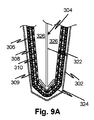
図9A〜図9Dは、様々なポケットフィルタ実施形態のポケット媒体および支持機構を示す。図9A〜図9Dの各々は単一のポケットの先端を示すが、任意のおよび全ての組み合わせにおいて、本明細書で説明される実施形態の特徴または従来技術による実施形態の互換特徴の任意の組み合わせを含むポケットフィルタ全体の構造において識別される特徴を説明するように理解される。図9Aを参照すると、フィルタ媒体は、互いに接着され、または単に互いに隣接し得る3層から形成される。第1の濾過層310はポケットの内側にあり、濾過されるガス流は最初に第1の濾過層310を通過する。第1の濾過層310は、ガス流が通過する最後の層である第2の濾過層306に比べて比較的低いフィルタ効率および高ロフトを有する目の粗い不織布で作られてよい。第2の濾過層306は、第1の濾過層310よりも大幅に高いフィルタ効率である点を除いて類似の材料で作られてよい。分離層308は本実施形態において分離層として機能し、第1および第3の濾過層と類似の構造であるが、第1の濾過層310よりも低い効率を有する。
9A-9D show pocket media and support mechanisms for various pocket filter embodiments. Each of FIGS. 9A-9D shows the tip of a single pocket, but in any and all combinations, any combination of the features of the embodiments described herein or the compatible features of the prior art embodiments. It is understood to explain the features identified in the overall structure of the pocket filter, including. With reference to FIG. 9A, the filter media are formed from three layers that can be adhered to each other or simply adjacent to each other. The
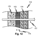
図9Aの実施形態(および開示される追加の実施形態)の特徴は、ここで図12を参照して説明される。第1の濾過層310は第1の濾過層170に対応し、第2の濾過層306は第1の濾過層174に対応する。分離層308は分離層172に対応する。図9Aの例において、層306〜310は相対フィルタ効率の点で異なるものとして説明された。フィルタ効率は、第1の濾過層170と第2の濾過層174(ならびに310と306)との区別に関連する。グリースエアゾールは比較的目が粗く低効率の媒体にも積極的に付着する傾向があるので、第2の濾過層174に対する第2の濾過層170の高いフィルタ効率は、グリース環境においてフィルタ層の均一な処理を容易にする。したがって非常に低い効率の媒体でも、グリースの捕捉には十分効率的である。しかし、目の粗さによって、第2の濾過層170は煙霧を迅速に遮断することなく通過させ続けるので、第2の濾過層174は、複合媒体114の全体能力に寄与するとともに、より小さな粒子を除去することができる。
The features of the embodiment (and additional embodiments disclosed) of FIG. 9A are described herein with reference to FIG. The
図9Aの実施形態に関して、分離層308は、濾過層308よりも低い効率を有するものとして説明された。しかし、(分離層308に対応する)分離層172の重要な機能は、第2の濾過層170の低効率媒体から第2の濾過層174の高効率媒体へのグリースのウィッキングを防止することである。したがって、分離層172の特徴は、2つの媒体間のウィッキング力の相対強度である。第2の濾過層170が第2の濾過層170よりも低い力を生じるようにすることで、分離層172は、より高いウィッキング力の媒体の第2の濾過層174が、より低いウィッキング力の媒体の第2の濾過層170の下流に隣接する配置を可能にする。
For the embodiment of FIG. 9A, the
実施形態において、分離層172は、第1の濾過層170によって捕捉されたグリースをこすり落として対流によってグリースを第2の濾過層174へ搬送し得るあらゆる乱流(または渦流など乱流の発端)を防止する格子または気泡構造を有する。あらゆる乱流(または乱流の発端または層状の崩壊というあらゆる種類の分離特徴)の防止は、流速の選択および特徴的な流動次元によって保証されてもよい。後者に関する最悪の場合の候補は、175で示される分離層172の幅であり得るが、分離層172の構造が同様の役割を果たす。実施形態において、分離層172は、横方向への(すなわち主流177の方向に垂直な)流れが防止され、または少なくとも強く抑制されるような抵抗を生じる役割も担ってよい。これは、第2の濾過層170からグリースを移動または脱離させ得る平均流を防止し得る。
In an embodiment, the
相対ウィッキング力の観点における媒体114の特徴の上記説明は、フィルタ効率の観点において図9A(およびその他)の実施形態に変換され得る。すなわち、(緊密にパックされ、または密度が高い)高効率媒体は、より高いウィッキング力(毛管力)を有する。よって、層の相対効率は、少なくとも同様の種類の媒体に関してウィッキング力の観点に変換される。 The above description of the characteristics of the medium 114 in terms of relative wicking forces can be translated into the embodiment of FIG. 9A (and others) in terms of filter efficiency. That is, a high efficiency medium (tightly packed or dense) has a higher wicking force (capillary force). Thus, the relative efficiency of the layers is translated in terms of wicking forces, at least for similar types of media.
上記実施形態および実施形態のいずれかにおいて、濾過層は、ガラス繊維を巻き付けるためのフェノール樹脂を備えた糸ガラスで作られてよい。別の実施形態において、濾過層は、たとえばポリエステルなどのポリマ繊維で作られてよい。オープンセル高ロフト不織布を形成するために他の材料が使用されてもよい。 In either of the above embodiments and embodiments, the filtration layer may be made of threaded glass with a phenolic resin around which the glass fibers are wound. In another embodiment, the filtration layer may be made of polymer fibers such as polyester. Other materials may be used to form the open cell high loft non-woven fabric.
図9Aに戻り、図14A〜図14Dも参照すると、内枠352は、多層媒体114、309のための機械的支持をもたらす。内枠352は、図9Aにおける304で示される。内枠304は、主けた322と、内側空間326を開いた状態に保つ先端スプレッダ324とを含む。外枠354は、ワイヤまたは他の任意の適当な材料で作られてよい。外枠は第2の濾過層174を支持し、第2の濾過層174は第1の濾過層170および分離層172を支持する。図9Aの実施形態において、外枠302は第2の濾過層309を支持し、第2の濾過層309は第1の濾過層310および分離層308を支持する。内枠352および外枠354は、溶接ワイヤ、プラスティック、または他の任意の適当な材料で作られてよい。同様に、外枠356および358の場合、発泡シート、金網フェンス(ツイストワイヤメッシュ)型材料などで作られてもよい。
Returning to FIG. 9A and also with reference to FIGS. 14A-14D, the
実施形態において、外枠は、媒体がより緩く目の粗いオープン構造であり、壊れるまで拡張する傾向があるほど弾性であり得ることを可能にする装置をもたらす。他の実施形態または同様の実施形態において、外枠は、図9Eに示すように媒体が伸張して隣接したポケット間の隙間を埋めることを防いでよく、ここで370は、弛緩状態にある隣接ポケットを示し、372は、排気システムによる加圧後の隣接ポケットを示す。 In embodiments, the outer frame provides a device that allows the medium to be a looser, coarser, open structure and elastic enough to tend to expand until it breaks. In other or similar embodiments, the outer frame may prevent the medium from stretching to fill the gaps between adjacent pockets, as shown in FIG. 9E, where 370 is a relaxed adjacency. Indicates a pocket, where 372 indicates an adjacent pocket after pressurization by the exhaust system.
図9Bは、(分離層308または172の特性を有していた)分離層312の材料が濾過層306および310のフィルタ媒体とは異なる種類の織物または材料で作られている点を除き、図9Bと同様の実施形態を示す。これは、媒体309の層が基本的には全て同じであるが様々な効率である(すなわち、明白なウィッキング力を含む)図9Aの実施形態とは異なる。使用され得る材料の例は、(波形の変形例を含む)発泡シートのスペーサ150の可撓性実施形態である。
FIG. 9B shows the figure 9B, except that the material of the separation layer 312 (which had the properties of the
図9Cは、外枠302が存在しない別の変形例を示す。図9Cのような実施形態において、分離層315は、内枠304にわたり緊密に引き寄せられ得る高い引張強度の点で選択された材料からなってよい。これは、図9Eに関して示されるような膨出効果を防止または軽減し得る。第1の濾過層306および第2の濾過層310の層は、高引張強度分離層315に接着されてよい。接着およびスペーサの高引張強度の組み合わせは、利点を享受したまま外枠302の代替を提供し得る。スペーサ150の例は、高引張強度を提供する。第1の濾過層310よりも低いウィッキング強度を有するスペーサ材料とともに任意選択的に、魚網のような目の粗い織布が利用されてよい。当業者には他の例が明らかである。
FIG. 9C shows another modification in which the
図9Dは、第2の濾過層314にバッキング層317が設けられた他の変形例を示す。バッキング層317はたとえば、第2の濾過層314の濾過媒体に接着積層された不織布であってよい。高引張強度によって外枠302の省略が可能である。バッキング層が有利に外側に設けられ、それによって、第2の濾過層314の出口点に高効率材料が使用されることが可能である。そのようなバッキングが第1の濾過層310または媒体の最後の層の上流において用いられた場合、これは早急に詰まり、開示される実施形態の長いフィルタ寿命の利益を損じ、これより下流の媒体を十分活用できないことがある。
FIG. 9D shows another modification in which the
図10A〜図10Cは、開示された主題事項の模範実施形態および従来技術水準に係るポケットフィルタの試験結果を示す。図10Aを参照すると、グラフは、圧力降下の関数として、ポケットフィルタ状に形成された様々なフィルタ媒体において累積された質量を示す。圧力降下における利得が多くの場合フィルタの交換を強いる条件であるため、所与の圧力降下に関して多量の濾過物質量を累積するフィルタは、頻度の少ない交換を要する。観察されるように、上記実施形態の多重濾過層特徴を欠くベースライン媒体は、5つの異なる質量の累積濾過物で示される、変化するレベルまで圧力降下が増加するまでに、低質量を処理する(本発明のフィルタ媒体例の相対的な有効性を説明するために、ここでフィルタ間に堆積する質量は変化する)。以下に、様々な例の構造を列挙する。
・ベースラインw/pre:ベースラインケース、2つのフィルタ、深さ2インチのプリーツ型パネルおよび深さ15インチの単層8ポケットフィルタ、両フィルタの全体深さは18インチ。
・M9S2M13 18”:模範的な多層8ポケットフィルタ、各ポケットは深さ18インチ、内側ポケットにはMERV9ガラス繊維、次に非常に目の粗い多孔質構造ポリエステル分離層、その次に最終MERV13ガラス繊維外側層がある。
・M9S2M14 18”:模範的な多層8ポケットフィルタ、各ポケットは深さ18インチ、内側ポケットにはMERV9ガラス繊維、次に非常に目の粗い多孔質構造ポリエステル分離層、その次に最終MERV14ガラス繊維外側層がある。M9M14:従来の2層8ポケットフィルタ、各ポケットは深さ18インチ、内側ポケットにはMERV9ガラス繊維、次に接触してMERV14ガラス繊維層がある。
また観察されるように、処理の観点から最も効率的な実施形態は、目の粗い多孔質ポリエステルの分離層を有する2つである。ベースラインは、深さ15インチの単層ポケットを備えたプリーツ型フィルタを有する。M9S2M13はM9S2M13よりも多くを処理したが、両者とも、ベースラインおよび分離層M9M14を有さず2層が直接接する2層ポケットである他よりも性能が優れていた。図10Bは、圧力降下対運転時間のフォーマットで同じ例を示す。観察されるように、分離層を有する2つの実施形態は、高い圧力降下によりフィルタ交換を要するまで最も長い運転時間があった。ベースラインの複数のピークは、前述の図面と同様にフィルタ交換の数を示す。
10A-10C show the model embodiments of the disclosed subject matter and the test results of the pocket filter according to the prior art level. With reference to FIG. 10A, the graph shows the cumulative mass in various filter media formed like pocket filters as a function of pressure drop. A filter that accumulates a large amount of filter material for a given pressure drop requires infrequent replacement because the gain in the pressure drop is often a condition that forces the filter to be replaced. As observed, the baseline medium lacking the multi-filter layer feature of the above embodiment treats a low mass until the pressure drop increases to varying levels, as shown by the cumulative filters of five different masses. (To illustrate the relative effectiveness of the example filter media of the present invention, the mass deposited here varies between filters). The structures of various examples are listed below.
-Baseline w / pre: Baseline case, 2 filters, 2-inch deep pleated panel and 15-inch deep single-layer 8-pocket filter, both filters have an overall depth of 18 inches.
Also, as observed, the most efficient embodiments from a processing point of view are the two having a coarse-meshed porous polyester separation layer. The baseline has a pleated filter with a 15 inch deep single layer pocket. M9S2M13 processed more than M9S2M13, but both performed better than the other, which had no baseline and no separation layer M9M14 and was a two-layer pocket with two layers in direct contact. FIG. 10B shows the same example in the pressure drop vs. run time format. As can be seen, the two embodiments with separate layers had the longest operating time before filter replacement was required due to the high pressure drop. Multiple peaks at the baseline indicate the number of filter changes, similar to the drawings above.
図11は、開示されるポケットフィルタ実施形態の応用コンテキストを示す。たとえばグリル用排気フードに使用されるカートリッジフィルタなどの衝撃フィルタ107が第1段階として用いられる。たとえば150の金属実施形態などのメッシュフィルタが第2段階として用いられる。次に、開示される実施形態に係るポケットフィルタ114が第3段階として用いられる。次に、たとえばプリーツ型フィルタなどの高性能微粒子捕捉(HEPA)フィルタが第4段階として用いられる。実施形態において、これらは特に、たとえば非通気式簡易型グリルなどの低汚染物質耐性用途において有用である。
FIG. 11 shows the application context of the disclosed pocket filter embodiments. For example, an
図13は、開示される主題事項の実施形態に係るポケットフィルタをガス流が自由に通過することを確実にするための特徴を表すためにポケットフィルタを断面図で示す。たとえば、ポケットを形成するために図11の構造の多層ポケットが使用される。ポケット間には、たとえば実施形態においてフィルタ媒体または分離層として別なふうに使用される目の粗い多孔質メッシュからなる拡張障壁202がある。拡張障壁202は、図9Eに示すように側壁が膨出しガス流が欠乏することを防ぐことによって、フィルタポケット204が膨張した時でもフィルタポケット204の側面からのガス流が妨げられないことを可能にする。拡張障壁202の厚さは、より厚い拡張障壁202の材料を示す210で示されるポケットフィルタ114媒体の対応するスペーサ層よりも大きいまたは小さくてよい。
FIG. 13 is a cross-sectional view of the pocket filter to represent features for ensuring that the gas stream freely passes through the pocket filter according to an embodiment of the disclosed subject matter. For example, a multi-layer pocket with the structure of FIG. 11 is used to form the pocket. Between the pockets is an
図15Aおよび図15Cは、開示される主題事項の実施形態に係るポケットフィルタをガス流が自由に通過することを確実にするために寄与する追加の特徴を示す。図15Aを参照すると、様々な実施形態のいずれかに係る媒体のポケット402は、たとえば図9Eを参照して説明したようなポケットの拡張を防止するために内側保持装置404を有し、これは糸であってよい。ここでは、枠403にポケットが取り付けられるように示される。これらの特徴は、開示される他の特徴のいずれかと組み合わせられて追加の実施形態を成してよい。図15Bは、挿入され、1または複数のスキュア406によって定位置に保たれるように固定され得る拡張障壁408を設ける方法を示す。図15Cは、図9Eを参照して説明したようなポケットの拡張を防止するための他の機構を示す。拡張障壁として機能するトング421を有する開放枠420がポケット403間に挿入される。枠420は、低い引張強度を有する非常に目の粗い媒体の使用を可能にするために外側ポケットを支持する機能も提供し得る。たとえば、ガラス繊維系媒体は、特にバッキングを有さない場合、この特徴を有する。
15A and 15C show additional features that contribute to ensure that the gas stream passes freely through the pocket filter according to the embodiment of the disclosed subject matter. Referring to FIG. 15A, the
図16Aおよび図16Bは、開示される主題事項の実施形態に係るポケットフィルタのポケットを形成する構造および方法を示す。単一の(本明細書で教示されるような多層からなってよい)シート状媒体440は、図示されるような位置にある三角形であってよいウェブ442とともに折り畳まれる。次に折り畳まれたシートの縁部がポケットの先端において447で示されるように縫い合わせられ、その後ポケットの根本に向かってウェブ442に縫い付けられる。シートは、図15A〜図16Bに示すような弾丸状の複数の隣接ポケットを形成するように途切れなく続いてよい。
16A and 16B show the structure and method of forming pockets of a pocket filter according to an embodiment of the disclosed subject matter. A single sheet medium (which may consist of multiple layers as taught herein) is folded with a
第1の実施形態によると、開示される主題事項は、汚染物質の流れを濾過するためのフィルタを含む。ポケットフィルタは、厚さ20mm未満を有し油相溶性材料である第1の媒体材料の第1のポケットを有する。ポケットフィルタは、厚さ20mm未満を有し油相溶性材料である第2の媒体材料の第2のポケットを含む。第2のポケットの第2の媒体材料は、上記第1の媒体材料よりも高効率である。第1のポケットは第2のポケット内に収まり、第2のポケットよりも短い深さを有し、第1および第2のポケットの間に隙間をもたらすスペーサを有し、スペーサは、開口面積率が50%を上回るように少なくとも2mmサイズの穴を有し、少なくとも3mmの最小間隔を画定する深さを有する。 According to the first embodiment, the disclosed subject matter includes a filter for filtering the flow of contaminants. The pocket filter has a first pocket of a first medium material having a thickness of less than 20 mm and being an oil-compatible material. The pocket filter includes a second pocket of a second medium material having a thickness of less than 20 mm and being an oil-compatible material. The second medium material in the second pocket is more efficient than the first medium material described above. The first pocket fits within the second pocket, has a shorter depth than the second pocket, has a spacer that provides a gap between the first and second pockets, and the spacer has an opening area ratio. Has a hole sized at least 2 mm such that is greater than 50% and has a depth defining a minimum spacing of at least 3 mm.
第1の実施形態は、第1のポケットの全ての点と第2のポケットの全ての点との間に効果的にエアギャップを画定する開放分離材を第1および第2のポケットの間に含む追加の第1の実施形態を成すように変更されてよい。第1の実施形態は、分離材が発泡プラスティック格子を含む追加の第1の実施形態を成すように変更されてよい。第1の実施形態は、分離材がワイヤフレームを含む追加の第1の実施形態を成すように変更されてよい。第1の実施形態は、ワイヤフレームが第1のポケットに取り付けられる追加の第1の実施形態を成すように変更されてよい。第1の実施形態は、第1のポケットがMERV9媒体からなり、第2のポケットがMERV14からなる追加の第1の実施形態を形成するように変更されてよい。 The first embodiment provides an open separator between the first and second pockets that effectively defines an air gap between all points in the first pocket and all points in the second pocket. It may be modified to form an additional first embodiment that includes. The first embodiment may be modified so that the separating material forms an additional first embodiment that includes a foamed plastic lattice. The first embodiment may be modified so that the separating material forms an additional first embodiment that includes a wire frame. The first embodiment may be modified to form an additional first embodiment in which the wire frame is attached to the first pocket. The first embodiment may be modified to form an additional first embodiment in which the first pocket is made of MERV9 medium and the second pocket is made of MERV14.
第2の実施形態によると、開示される主題事項は、汚染物質の流れを濾過するためのフィルタを有する排気システムを含む。グリースフィルタおよびダクト配管を有する排気フードは、グリースフィルタの下流でポケットフィルタを支持するように適合される。排気ネットワークにおいてグリースフィルタに後続してポケットフィルタがある。ポケットフィルタは、20mm未満の厚さを有し、油相溶性材料である第1の媒体材料の第1のポケットを含む。ポケットフィルタは、厚さ20mm未満を有し、油相溶性材料である第2の媒体材料の第2のポケットを含む。第2のポケットの第2の媒体材料は、上記第1の媒体材料よりも高効率である。 According to a second embodiment, the disclosed subject matter includes an exhaust system having a filter for filtering the flow of pollutants. Exhaust hoods with grease filters and duct piping are adapted to support pocket filters downstream of the grease filters. There is a pocket filter following the grease filter in the exhaust network. The pocket filter has a thickness of less than 20 mm and includes a first pocket of a first medium material that is an oil compatible material. The pocket filter has a thickness of less than 20 mm and includes a second pocket of a second medium material which is an oil compatible material. The second medium material in the second pocket is more efficient than the first medium material described above.
第2の実施形態は、第1のポケットの全ての点と第2のポケットの全ての点との間に効果的にエアギャップを画定する開放分離材を第1および第2のポケットの間に含む追加の第2の実施形態を成すように変更されてよい。第2の実施形態は、分離材が発泡プラスティック格子を含む追加の第2の実施形態を成すように変更されてよい。第2の実施形態は、分離材がワイヤフレームを含む追加の第2の実施形態を成すように変更されてよい。第2の実施形態は、ワイヤフレームが第1のポケットに取り付けられる追加の第2の実施形態を成すように変更されてよい。第2の実施形態は、第1のポケットがMERV11媒体からなり、第2のポケットがMERV14からなる追加の第2の実施形態を成すように変更されてよい。第2の実施形態は、第1のポケットが第2のポケット内に収まり、第2のポケットよりも短い深さを有することによって、空気流による膨張時に第1および第2のポケットが実質的に分離されるように、第1のポケットの流れ方向深さの少なくとも15%である流れ方向分離距離が第1のポケットおよび第2のポケットの下流端の間に存在する、追加の第2の実施形態を成すように変更されてよい。 A second embodiment provides an open separator between the first and second pockets that effectively defines an air gap between all points in the first pocket and all points in the second pocket. It may be modified to form an additional second embodiment that includes. The second embodiment may be modified so that the separator forms an additional second embodiment that includes a foamed plastic lattice. The second embodiment may be modified so that the separating material forms an additional second embodiment that includes a wire frame. The second embodiment may be modified to form an additional second embodiment in which the wire frame is attached to the first pocket. The second embodiment may be modified so that the first pocket comprises a MERV11 medium and the second pocket comprises an additional second embodiment consisting of a MERV14. In a second embodiment, the first pocket fits within the second pocket and has a shorter depth than the second pocket so that the first and second pockets are substantially inflated by airflow. An additional second practice in which a flow direction separation distance, which is at least 15% of the flow direction depth of the first pocket, is between the first pocket and the downstream end of the second pocket so as to be separated. It may be modified to form a form.
第3の実施形態によると、開示される主題事項は、汚染物質の流れを濾過するためのフィルタを含む。ポケットフィルタは、20mm未満の厚さを有し油相溶性材料である第1の媒体材料の第1のポケットを含む。ポケットフィルタは、20mm未満の厚さを有し油相溶性材料である第2の媒体材料の第2のポケットを含む。第2のポケットの第2の媒体材料は、上記第1の媒体材料よりも高効率である。第1のポケットは第2のポケット内に収まり、第2のポケットよりも短い深さを有することによって、空気流による膨張時に第1および第2のポケットが実質的に分離されるように、第1のポケットの流れ方向深さの少なくとも15%である流れ方向分離距離が第1のポケットおよび第2のポケットの下流端の間に存在する。 According to a third embodiment, the disclosed subject matter includes a filter for filtering the flow of contaminants. The pocket filter includes a first pocket of a first medium material having a thickness of less than 20 mm and being an oil-compatible material. The pocket filter includes a second pocket of a second medium material having a thickness of less than 20 mm and being an oil-compatible material. The second medium material in the second pocket is more efficient than the first medium material described above. The first pocket fits within the second pocket and has a shorter depth than the second pocket so that the first and second pockets are substantially separated during expansion by airflow. A flow direction separation distance, which is at least 15% of the flow direction depth of one pocket, exists between the downstream ends of the first pocket and the second pocket.
第3の実施形態は、第1のポケットの全ての点と第2のポケットの全ての点との間に効果的にエアギャップを画定する開放分離材を第1および第2のポケットの間に含む追加の第3の実施形態を成すように変更されてよい。第3の実施形態は、分離材が発泡プラスティック格子を含む追加の第3の実施形態を成すように変更されてよい。第3の実施形態は、分離材がワイヤフレームを含む追加の第3の実施形態を成すように変更されてよい。第3の実施形態は、ワイヤフレームが第1のポケットに取り付けられる追加の第3の実施形態を成すように変更されてよい。第3の実施形態は、第1のポケットがMERV9媒体からなり、第2のポケットがMERV14からなる追加の第3の実施形態を成すように変更されてよい。 A third embodiment provides an open separator between the first and second pockets that effectively defines an air gap between all points in the first pocket and all points in the second pocket. It may be modified to form an additional third embodiment that includes. The third embodiment may be modified so that the separating material forms an additional third embodiment that includes a foamed plastic lattice. The third embodiment may be modified so that the separating material forms an additional third embodiment that includes a wire frame. The third embodiment may be modified to form an additional third embodiment in which the wire frame is attached to the first pocket. The third embodiment may be modified so that the first pocket comprises a MERV9 medium and the second pocket comprises an additional third embodiment consisting of a MERV14.
上記から明らかであるように、分離層(またはセパレータまたはスペーサ、またはその他同一とみなされるもの)は、様々な構造からなってよい。好適には、それは可撓性が高いものである。厚さは、ウィッキングを抑止または防止するのに十分であるように実験によって決定されてよい。第1および第2の濾過層の相対効率は、試験状況下で、終了時点で2つの処理量がおおよそ同じ質量であるように選択される。実施形態において、第1の濾過層は8以下のMERVレーティングを有してよく、第2の濾過層は13以上のMERVレーティングを有してよい。実施形態において、第1の濾過層は6以下のMERVレーティングを有してよく、第2の濾過層は13以上のMERVレーティングを有してよい。実施形態において、後者の実施形態は、たとえば空気濾過フィルタにおいて使用されるようなガラス繊維からなる。 As is clear from the above, the separating layer (or separator or spacer, or otherwise considered identical) may consist of various structures. Preferably, it is highly flexible. The thickness may be determined experimentally to be sufficient to suppress or prevent wicking. The relative efficiencies of the first and second filtration layers are selected under test conditions so that at the end of the process, the two treated volumes are approximately the same mass. In embodiments, the first filtration layer may have a MERV rating of 8 or less and the second filtration layer may have a MERV rating of 13 or more. In embodiments, the first filtration layer may have a MERV rating of 6 or less and the second filtration layer may have a MERV rating of 13 or more. In embodiments, the latter embodiment consists of glass fibers, such as those used in air filtration filters.
ターゲットの液体を吸い上げる様々な傾向を有する様々な材料を特徴付けるために、ウィッキング強度という用語が用いられ得る。高いウィッキング強度を有する材料は、低いウィッキング強度を有する材料よりも強い毛管力を生じる。材料が互いに隣接して配置された場合、高ウィッキング強度材料から低ウィッキング強度材料へ液体が移動する傾向は、逆方向へ移動する傾向よりも低くなる。ウィッキング強度は、材料表面(たとえば疎水性または疎油性のナノ表面組織)、構造(たとえば繊維密度または孔径)、または組成(ポリマ、ガラス、金属、布ヤードなど)の特性であってよい。 The term wicking strength can be used to characterize different materials that have different tendencies to suck up the target liquid. A material having a high wicking strength produces a stronger capillary force than a material having a low wicking strength. When the materials are placed adjacent to each other, the tendency of the liquid to move from the high wicking strength material to the low wicking strength material is less than the tendency to move in the opposite direction. Wicking strength can be a property of the material surface (eg, hydrophobic or oleophobic nanosurface structure), structure (eg, fiber density or pore size), or composition (polymer, glass, metal, cloth yard, etc.).
本明細書で用いられる場合、MERVレーティングとは、米国暖房冷凍空調学会(ASHRAE)§52.2の定義を参照する。 As used herein, MERV rating refers to the definition in ASHRAE §52.2.
第1の実施形態によると、開示される主題事項は、分離層に隣接した、濾過材からなる第1および第2の濾過層を有するフィルタを含み、分離層は、第1の濾過層よりも低いウィッキング強度を有する。フィルタは、第1の濾過層から第2の濾過層へガスが流れるように好適な設置方向を有する。 According to the first embodiment, the disclosed subject matter includes a filter having first and second filtration layers made of filter media adjacent to the separation layer, the separation layer being more than the first filtration layer. Has low wicking strength. The filter has a suitable installation direction so that gas flows from the first filtration layer to the second filtration layer.
第1の実施形態は、支持枠を含む変形例を含み、好適な設置方向は支持枠において示される。 The first embodiment includes a modification including a support frame, and a suitable installation direction is indicated by the support frame.
第1の実施形態は、第1および第2の濾過層が不織形式のガラスまたはポリマ繊維を含む変形例を含む。 The first embodiment includes a modification in which the first and second filtration layers contain non-woven glass or polymer fibers.
第1の実施形態は、第1および第2の濾過層が不織形式の接着ガラスまたはポリマ繊維を含む変形例を含む。 The first embodiment includes modifications in which the first and second filtration layers contain non-woven adhesive glass or polymer fibers.
第1の実施形態は、第1および第2の濾過層が、高ロフトオープンセルマトリクスを形成する不織形式のガラスまたはポリマ繊維を含む変形例を含む。 The first embodiment includes modifications in which the first and second filtration layers contain non-woven glass or polymer fibers that form a high loft open cell matrix.
第1の実施形態は、第1の濾過層が第2の濾過層よりも高いウィッキング強度を有する変形例を含む。 The first embodiment includes a modification in which the first filtration layer has a higher wicking strength than the second filtration layer.
第1の実施形態は、第1および第2の濾過層および分離層が単一の多層織物を形成する変形例を含む。 The first embodiment includes a modification in which the first and second filtration layers and separation layers form a single multilayer fabric.
第1の実施形態は、第1および第2の濾過層および分離層が、ポケット状に形成された単一の多層織物シートを形成する変形例を含む。 The first embodiment includes a modification in which the first and second filtration layers and separation layers form a single multilayer fabric sheet formed in a pocket shape.
第1の実施形態は、第1および第2の濾過層および分離層が、ポケットフィルタとして構成されたポケットを形成する変形例を含む。 The first embodiment includes a modification in which the first and second filtration layers and separation layers form a pocket configured as a pocket filter.
第1の実施形態は、第1および第2の濾過層および分離層がポケットフィルタのポケットを形成し、隣接ポケットの壁部が直接接触することを防ぐように配置されたオープンセル材料をポケット間に更に備え、オープンセル材料はガスを通すことが可能である、変形例を含む。 In the first embodiment, the first and second filtration layers and separation layers form pockets of the pocket filter, and open cell material arranged so as to prevent direct contact between the walls of adjacent pockets is provided between the pockets. In addition, the open cell material is capable of passing gas, including modifications.
第1の実施形態は、第1および第2の濾過層および分離層がポケットフィルタのポケットを形成し、各部分がポケットの各々の内部に伸長する枠を更に備える変形例を含む。 The first embodiment includes a modification in which the first and second filtration layers and separation layers form pockets of a pocket filter, further comprising a frame in which each portion extends into each of the pockets.
第1の実施形態は、第1および第2の濾過層および分離層が、ポケットフィルタとして構成されたポケットを形成し、第1の濾過層は均一な構造からなるが、第2の濾過層は、第2の濾過層の他の部分よりも高い引張強度のバッキングを有することによって第1の濾過層および分離層を支持する、変形例を含む。 In the first embodiment, the first and second filtration layers and separation layers form pockets configured as pocket filters, the first filtration layer having a uniform structure, but the second filtration layer Includes modifications that support the first filtration layer and separation layer by having a backing of higher tensile strength than the rest of the second filtration layer.
第1の実施形態は、第1および第2の濾過層および分離層が、ポケットフィルタとして構成されたポケットを形成し、第1の濾過層および第2の濾過層は、第1または第2の濾過層の他の部分よりも高い引張強度のバッキングを有さない均一構造からなり、分離層は第1または第2の濾過層よりも高い引張強度を有し、第1および第2の濾過層が分離層に接着されることによって分離層が第1および第2の濾過層を支持する変形例を含む。 In the first embodiment, the first and second filtration layers and separation layers form pockets configured as pocket filters, and the first filtration layer and the second filtration layer are the first or second filtration layers. It consists of a uniform structure with no backing of higher tensile strength than the rest of the filter layer, the separation layer has higher tensile strength than the first or second filter layer, and the first and second filter layers. Includes a modification in which the separation layer supports the first and second filtration layers by adhering to the separation layer.
第1の実施形態は、第1および第2の濾過層および分離層が、ポケットフィルタとして構成されたポケットを形成し、第1の濾過層および第2の濾過層は、第1または第2の濾過層の他の部分よりも高い引張強度のバッキングを有さない均一構造からなり、各ポケットを取り巻いて隣接ポケットの壁が膨張によって互いに接触することを防ぐ外枠を更に備える変形例を含む。 In the first embodiment, the first and second filtration layers and separation layers form a pocket configured as a pocket filter, and the first filtration layer and the second filtration layer are the first or second filtration layer. Included are variants that consist of a uniform structure with no backing of higher tensile strength than the rest of the filtration layer and further include an outer frame that surrounds each pocket and prevents the walls of adjacent pockets from coming into contact with each other due to expansion.
第1の実施形態は、第1および第2の濾過層が分離層に接着された変形例を含む。 The first embodiment includes a modification in which the first and second filtration layers are adhered to the separation layer.
第1の実施形態は、第1および第2の濾過層および分離層が、ポケットフィルタのポケットを形成し、各部分がポケットの各々の内側へ伸長する第2の枠を更に備える変形例を含む。 The first embodiment includes a modification in which the first and second filtration layers and separation layers form pockets of a pocket filter, further comprising a second frame in which each portion extends inward of each of the pockets. ..
第2の実施形態によると、開示される主題事項は、オープンセル材料からなる第1、第2、および第3の層を有する濾過布を含む。第1の層は、第3の層よりも低い粒子捕捉効率を有する。第1の層は、第3の層よりも低いウィッキング強度を有する。第2の層は第1および第2の層の間にある。第2の層は、第1の層よりも低いウィッキング強度を有する。 According to a second embodiment, the disclosed subject matter includes a filter cloth having first, second, and third layers of open cell material. The first layer has a lower particle capture efficiency than the third layer. The first layer has a lower wicking strength than the third layer. The second layer is between the first and second layers. The second layer has a lower wicking strength than the first layer.
第2の実施形態は、第1および第2の層が不織織物からなる変形例を含む。 The second embodiment includes a modification in which the first and second layers are made of non-woven fabric.
第2の実施形態は、第1および第2の層が接着ガラス繊維からなる変形例を含む。 The second embodiment includes a modification in which the first and second layers are made of adhesive glass fiber.
第2の実施形態は、第1および第2の層が接着ポリマ繊維からなる変形例を含む。 The second embodiment includes a modification in which the first and second layers are made of adhesive polymer fibers.
第2の実施形態は、濾過布がポケット状に形成された変形例を含む。 The second embodiment includes a modification in which the filter cloth is formed in a pocket shape.
第2の実施形態は、濾過布がポケット状に形成された変形例を含む。 The second embodiment includes a modification in which the filter cloth is formed in a pocket shape.
第3の実施形態によると、開示される主題事項は、汚染物質の流れを濾過するためのフィルタを含む。ポケットフィルタは、20mm未満の厚さを有し油相溶性材料である第1の媒体材料からなる第1のポケットを有する。ポケットフィルタは、20mm未満の厚さを有し油相溶性材料である第2の媒体材料からなる第2のポケットを含む。第2のポケットの第2の媒体材料は、第1の媒体材料よりも高効率である。第1のポケットは第2のポケット内に収まり、第2のポケットよりも短い深さ(または第2のポケットと同じ長さ)を有し、第1および第2のポケットの間に隙間をもたらすスペーサを有し、スペーサは、開口面積率が50%を上回るように少なくとも2mmサイズの穴を有し、少なくとも3mmの最小間隔を画定する深さを有する。 According to a third embodiment, the disclosed subject matter includes a filter for filtering the flow of contaminants. The pocket filter has a first pocket having a thickness of less than 20 mm and made of a first medium material that is an oil-compatible material. The pocket filter includes a second pocket having a thickness of less than 20 mm and made of a second medium material which is an oil-compatible material. The second medium material in the second pocket is more efficient than the first medium material. The first pocket fits within the second pocket, has a shorter depth (or the same length as the second pocket) than the second pocket, and provides a gap between the first and second pockets. It has a spacer, the spacer having a hole sized at least 2 mm such that the opening area ratio exceeds 50% and having a depth defining a minimum spacing of at least 3 mm.
第3の実施形態は、第1のポケットの全ての点と第2のポケットの全ての点との間にエアギャップまたは流れ抵抗媒体を効果的に画定する開放分離材を第1および第2のポケットの間に含む変形例を含む。 A third embodiment provides first and second open separators that effectively define an air gap or flow resistance medium between all points in the first pocket and all points in the second pocket. Includes variants included between pockets.
第3の実施形態は、流れ抵抗媒体が第1のポケットの媒体よりも低いウィッキング強度を有する変形例を含む。 A third embodiment includes a modification in which the flow resistance medium has a lower wicking strength than the medium in the first pocket.
第3の実施形態は、分離材が発泡プラスティック格子を含む変形例を含む。 The third embodiment includes a modification in which the separating material includes a foamed plastic lattice.
第3の実施形態は、分離材がワイヤフレームを含む変形例を含む。 The third embodiment includes a modification in which the separating material includes a wire frame.
第3の実施形態は、ワイヤフレームが第1のポケットに取り付けられる変形例を含む。 The third embodiment includes a modification in which the wire frame is attached to the first pocket.
第3の実施形態は、第1のポケットがMERV9媒体からなり、第2のポケットがMERV14からなる変形例を含む。 The third embodiment includes a modification in which the first pocket is made of MERV9 medium and the second pocket is made of MERV14.
第4の実施形態によると、開示される主題事項は、汚染物質の流れを濾過するためのフィルタを有する排気システムを含む。排気フードは、グリースフィルタ、およびグリースフィルタの下流でポケットフィルタを支持するために適合されたダクト配管を有する。排気ネットワークにおいて、グリースフィルタの後にポケットフィルタが配置される。ポケットフィルタは、20mm未満の厚さを有し油相溶性材料である第1の媒体材料からなる第1のポケットを含む。ポケットフィルタは、20mm未満の厚さを有し油相溶性材料である第2の媒体材料からなる第2のポケットを含む。第2のポケットの第2の媒体材料は、第1の媒体材料よりも高効率である。 According to a fourth embodiment, the disclosed subject matter includes an exhaust system having a filter for filtering the flow of pollutants. The exhaust hood has a grease filter and duct piping adapted to support the pocket filter downstream of the grease filter. In the exhaust network, a pocket filter is placed after the grease filter. The pocket filter includes a first pocket having a thickness of less than 20 mm and made of a first medium material that is an oil-compatible material. The pocket filter includes a second pocket having a thickness of less than 20 mm and made of a second medium material which is an oil-compatible material. The second medium material in the second pocket is more efficient than the first medium material.
第4の実施形態は、第1のポケットの全ての点と第2のポケットの全ての点との間にエアギャップを効果的に画定する開放分離材を第1および第2のポケットの間に含む変形例を含む。 A fourth embodiment provides an open separator between the first and second pockets that effectively defines an air gap between all points in the first pocket and all points in the second pocket. Includes modified examples.
第4の実施形態は、分離材が発泡プラスティック格子を含む変形例を含む。 The fourth embodiment includes a modification in which the separating material includes a foamed plastic lattice.
第4の実施形態は、分離材がワイヤフレームを含む変形例を含む。 A fourth embodiment includes a modification in which the separating material includes a wire frame.
第4の実施形態は、ワイヤフレームが第1のポケットに取り付けられる変形例を含む。 A fourth embodiment includes a modification in which the wire frame is attached to the first pocket.
第4の実施形態は、第1のポケットがMERV11媒体からなり、第2のポケットがMERV14からなる変形例を含む。 The fourth embodiment includes a modification in which the first pocket is made of MERV11 medium and the second pocket is made of MERV14.
第4の実施形態は、第1のポケットが第2のポケット内に収まり、第2のポケットよりも短い深さを有することによって、空気流による膨張時に第1および第2のポケットが実質的に分離されるように、第1のポケットの流れ方向深さの少なくとも15%である流れ方向分離距離が第1のポケットおよび第2のポケットの下流端の間に存在する変形例を含む。 In a fourth embodiment, the first pocket fits within the second pocket and has a shorter depth than the second pocket so that the first and second pockets are substantially inflated by airflow. It includes a variant in which a flow direction separation distance, which is at least 15% of the flow direction depth of the first pocket, exists between the downstream ends of the first pocket and the second pocket so as to be separated.
第5の実施形態によると、開示される主題事項は、汚染物質の流れを濾過するためのフィルタを含む。ポケットフィルタは、20mm未満の厚さを有し油相溶性材料である第1の媒体材料からなる第1のポケットを含む。ポケットフィルタは、20mm未満の厚さを有し油相溶性材料である第2の媒体材料からなる第2のポケットを含む。第2のポケットの第2の媒体材料は、第1の媒体材料よりも高効率である。第1のポケットは第2のポケット内に収まり、第2のポケットよりも短い深さ(または第2のポケットと同じ長さ)を有することによって、空気流による膨張時に第1および第2のポケットが実質的に分離されるように、第1のポケットの流れ方向深さの少なくとも15%である流れ方向分離距離が第1のポケットおよび第2のポケットの下流端の間に存在してよい。 According to a fifth embodiment, the disclosed subject matter includes a filter for filtering the flow of contaminants. The pocket filter includes a first pocket having a thickness of less than 20 mm and made of a first medium material that is an oil-compatible material. The pocket filter includes a second pocket having a thickness of less than 20 mm and made of a second medium material which is an oil-compatible material. The second medium material in the second pocket is more efficient than the first medium material. The first pocket fits within the second pocket and has a shorter depth (or the same length as the second pocket) than the second pocket, so that the first and second pockets are inflated by airflow. A flow direction separation distance, which is at least 15% of the flow direction depth of the first pocket, may exist between the downstream ends of the first pocket and the second pocket so that is substantially separated.
第5の実施形態は、第1のポケットの全ての点と第2のポケットの全ての点との間にエアギャップを効果的に画定する開放分離材を第1および第2のポケットの間に含む変形例を含む。 A fifth embodiment provides an open separator between the first and second pockets that effectively defines an air gap between all points in the first pocket and all points in the second pocket. Includes modified examples.
第5の実施形態は、分離材が発泡プラスティック格子を含む変形例を含む。 A fifth embodiment includes a modification in which the separating material includes a foamed plastic lattice.
第5の実施形態は、分離材がワイヤフレームを含む変形例を含む。 A fifth embodiment includes a modification in which the separating material includes a wire frame.
第5の実施形態は、ワイヤフレームが第1のポケットに取り付けられる変形例を含む。 A fifth embodiment includes a modification in which the wire frame is attached to the first pocket.
第5の実施形態は、第1のポケットがMERV9媒体からなり、第2のポケットがMERV14からなる変形例を含む。 A fifth embodiment includes a modification in which the first pocket is made of MERV9 medium and the second pocket is made of MERV14.
第6の実施形態によると、開示される主題事項は、ガス流から煙霧を浄化する方法を含む。方法は、グリース付帯煙霧を第1の深さの処理フィルタに通し、その後第2の深さの処理フィルタ媒体に通して流すことを含む。方法は、多孔質分離材によって、第1および第2の深さの処理フィルタの間の隙間を維持することを含む。第1の深さの処理フィルタは、第2の深さの処理フィルタよりも低い効率レーティングを有する。多孔質媒体は、第1の深さの処理フィルタよりも低い効率を有し、多孔性分離材、第1の深さの処理フィルタ、および第2の深さの処理フィルタは全て、不織繊維からなる。 According to a sixth embodiment, the disclosed subject matter includes a method of purifying fumes from a gas stream. The method comprises passing the greased fumes through a first depth treatment filter and then through a second depth treatment filter medium. The method comprises maintaining a gap between the first and second depth treatment filters with a porous separator. The first depth processing filter has a lower efficiency rating than the second depth processing filter. The porous medium has lower efficiency than the first depth treatment filter, and the porous separator, the first depth treatment filter, and the second depth treatment filter are all non-woven fibers. Consists of.
第6の実施形態は、第1の深さの処理フィルタが、バッキング層を有さない均一な不織繊維からなる変形例を含む。 A sixth embodiment includes a modification in which the first depth treatment filter is made of uniform non-woven fibers without a backing layer.
第6の実施形態は、第2の深さの処理フィルタが、第2の深さの処理フィルタの他の部分よりも高い引張強度のバッキング層を有し、バッキング層はその下流面にあり、方法は、第1の深さの処理フィルタ、多孔質媒体、および第2の深さの処理フィルタを支持することを更に備える変形例を含む。 In a sixth embodiment, the second depth processing filter has a backing layer with a higher tensile strength than the other parts of the second depth processing filter, and the backing layer is on its downstream surface. The method further comprises supporting a first depth treatment filter, a porous medium, and a second depth treatment filter.
第6の実施形態は、多孔質分離材が均一な不織繊維からなる変形例を含む。 The sixth embodiment includes a modification in which the porous separating material is made of uniform non-woven fibers.
第6の実施形態は、多孔質媒体が第1の深さの処理フィルタよりも高い引張強度を有する変形例を含む。 The sixth embodiment includes a modification in which the porous medium has a higher tensile strength than the treatment filter of the first depth.
「ウィッキング効率」という用語を用いて説明された実施形態のいずれかにおいて、場合によってはウィッキング効率の代わりに「濾過効率」という用語を用いる様々な実施形態として説明されてもよい。または別の例として、「毛管力」、「密度」、または「MERVレーティング」がウィッキング効率の代わりとして用いられてよい。 In any of the embodiments described with the term "wicking efficiency", it may be described as various embodiments using the term "filtration efficiency" instead of the wicking efficiency in some cases. Alternatively, as another example, "capillary force", "density", or "MERV rating" may be used as an alternative to wicking efficiency.
このように、本開示に従って、フィルタ装置の方法およびシステムが提供されることが明らかである。本開示によって、多数の代替例、変更例、および変形例が可能となる。開示された実施形態の特徴は、追加の実施形態を生み出すために、本発明の範囲内で組み合わせ、並べ替え、省略などされてよい。また、特定の特徴は、場合によっては、対応する他の特徴の使用を伴わずに有利に用いられてもよい。したがって、出願人は、本発明の主旨および範囲に収まるそのような代替例、変更例、均等物、および変形例の全てを包含することを意図している。 Thus, it is clear that the methods and systems of filter devices are provided in accordance with the present disclosure. The present disclosure allows for a number of alternatives, modifications, and variations. The features of the disclosed embodiments may be combined, rearranged, omitted, etc. within the scope of the present invention to produce additional embodiments. Also, certain features may optionally be used advantageously without the use of other corresponding features. Accordingly, the Applicant intends to include all such alternatives, modifications, equivalents, and variants that fall within the spirit and scope of the present invention.
Claims (16)
互いに隣接して配置された複数のポケットフィルタ(9、204)であって、前記ポケットフィルタ(9、204)の各々は、20mm未満の厚さを有しかつ油相溶性材料の第1の媒体材料(34、310)の第1のポケット(12)、および20mm未満の厚さを有しかつ油相溶性材料の第2の媒体材料(30、306)の第2のポケット(10)を含む、ポケットフィルタと、
前記複数のポケットフィルタ(9、204)のうち隣接するポケットフィルタの間にある拡張障壁(202、408)であって、前記拡張障壁(202、408)は、前記隣接するポケットフィルタの壁が直接接触することを防ぐオープンセル材料を含むと同時に、ガスが前記オープンセル材料を通って流れることを可能にする、拡張障壁と、
を備え、
前記第2の媒体材料(30、306)は前記第1の媒体材料(34、310)よりも高い効率を有し、
前記第1のポケット(12)は、前記第2のポケット(10)内に収まり、かつ前記第2のポケット(10)の深さよりも短い深さを有し、
スペーサ(15、18、32)が、前記第1のポケット(12)および前記第2のポケット(10)の間に配置され、かつ前記第1のポケット(12)および前記第2のポケット(10)の間に隙間をもたらし、
前記スペーサ(15、18、32)は、50%よりも大きい開口面積率を有する、サイズにおいて少なくとも2mmの穴、および少なくとも3mmの最小間隔を画定する深さを有する、ポケットフィルタアセンブリ。 A pocket filter assembly (6) for filtering the flow of contaminants, said pocket filter assembly (6).
A plurality of pocket filters (9,204) arranged adjacent to each other, each of which has a thickness of less than 20 mm and is a first medium of oil-compatible material. Includes a first pocket (12) of material (34, 310) and a second pocket (10) of a second medium material (30, 306) having a thickness of less than 20 mm and an oil-compatible material. , Pocket filter and
An expansion barrier (202, 408) between adjacent pocket filters among the plurality of pocket filters (9, 204), wherein the expansion barrier (202, 408) is directly connected to the wall of the adjacent pocket filter. With an expansion barrier, which contains an open cell material that prevents contact, while allowing gas to flow through the open cell material.
With
The second medium material (30, 306) has higher efficiency than the first medium material (34, 310).
The first pocket (12) fits within the second pocket (10) and has a depth shorter than the depth of the second pocket (10).
Spacers (15, 18, 32) are arranged between the first pocket (12) and the second pocket (10), and the first pocket (12) and the second pocket (10). ), Bringing a gap between
The spacers (15, 18, 32) are pocket filter assemblies having a hole area ratio greater than 50%, a hole of at least 2 mm in size, and a depth defining a minimum spacing of at least 3 mm.
グリースフィルタ、および前記グリースフィルタの下流で前記ポケットフィルタアセンブリを支持するように適合されたダクト配管を有する排気フードと、
排気ネットワークにおいて前記ポケットフィルタアセンブリが後続するグリースフィルタと、
を更に備える、システム。 An exhaust system having the pocket filter assembly according to any one of claims 1 to 14.
An exhaust hood with a grease filter and duct piping adapted to support the pocket filter assembly downstream of the grease filter.
A grease filter followed by the pocket filter assembly in the exhaust network,
A system that further prepares.
Applications Claiming Priority (3)
| Application Number | Priority Date | Filing Date | Title |
|---|---|---|---|
| US201562239844P | 2015-10-09 | 2015-10-09 | |
| US62/239,844 | 2015-10-09 | ||
| PCT/US2016/056204 WO2017062926A2 (en) | 2015-10-09 | 2016-10-09 | Filter devices methods and system |
Publications (3)
| Publication Number | Publication Date |
|---|---|
| JP2018534129A JP2018534129A (en) | 2018-11-22 |
| JP2018534129A5 JP2018534129A5 (en) | 2019-11-14 |
| JP6836587B2 true JP6836587B2 (en) | 2021-03-03 |
Family
ID=58488690
Family Applications (1)
| Application Number | Title | Priority Date | Filing Date |
|---|---|---|---|
| JP2018517860A Active JP6836587B2 (en) | 2015-10-09 | 2016-10-09 | Filter device method and system |
Country Status (19)
| Country | Link |
|---|---|
| US (1) | US10835851B2 (en) |
| EP (1) | EP3359275B1 (en) |
| JP (1) | JP6836587B2 (en) |
| KR (1) | KR102380816B1 (en) |
| CN (1) | CN108136299B (en) |
| AU (1) | AU2016334382B2 (en) |
| BR (1) | BR112018006846B1 (en) |
| CA (1) | CA3001319C (en) |
| CL (1) | CL2018000875A1 (en) |
| CO (1) | CO2018004329A2 (en) |
| DK (1) | DK3359275T3 (en) |
| HK (1) | HK1252964A1 (en) |
| MX (1) | MX2018004226A (en) |
| MY (1) | MY195053A (en) |
| PE (1) | PE20181257A1 (en) |
| PL (1) | PL3359275T3 (en) |
| SG (1) | SG10201914010TA (en) |
| WO (1) | WO2017062926A2 (en) |
| ZA (1) | ZA201802868B (en) |
Families Citing this family (6)
| Publication number | Priority date | Publication date | Assignee | Title |
|---|---|---|---|---|
| WO2017023936A1 (en) * | 2015-08-03 | 2017-02-09 | Parker-Hannifin Corporation | Filter with preferential air flow |
| TW202045866A (en) | 2019-02-05 | 2020-12-16 | 芬蘭商歐伊霍頓集團公司 | Cooking pollutant control methods devices and systems |
| CN111853882B (en) * | 2019-04-28 | 2023-06-16 | 博西华电器(江苏)有限公司 | Smoke exhaust ventilator and filtering device thereof |
| CN112755679A (en) * | 2019-11-04 | 2021-05-07 | 康宁股份有限公司 | Air purifier |
| CN212214919U (en) * | 2019-11-04 | 2020-12-25 | 康宁股份有限公司 | Air purifier |
| IT202000027516A1 (en) * | 2020-11-17 | 2022-05-17 | Faber Spa | IMPROVED FILTER GROUP FOR EXTRACTOR HOOD |
Family Cites Families (67)
| Publication number | Priority date | Publication date | Assignee | Title |
|---|---|---|---|---|
| US3364664A (en) | 1964-07-20 | 1968-01-23 | Cockle Ventilator Company Inc | Grease extractor for ventilating systems |
| US3376804A (en) | 1966-05-23 | 1968-04-09 | Cockle Ventilator Company Inc | Dripless grease extractor for kitchen hoods |
| US3494113A (en) | 1968-05-22 | 1970-02-10 | Microtron Corp | Air filter assembly and sub-assemblies |
| CA885589A (en) | 1968-10-03 | 1971-11-09 | Industrial Air Filters Limited | High efficiency air filter |
| US3566585A (en) | 1969-07-07 | 1971-03-02 | Mona A Voloshen | Grease-extracting apparatus |
| CA962021A (en) | 1970-05-21 | 1975-02-04 | Robert W. Gore | Porous products and process therefor |
| US3962153A (en) | 1970-05-21 | 1976-06-08 | W. L. Gore & Associates, Inc. | Very highly stretched polytetrafluoroethylene and process therefor |
| US3813856A (en) | 1972-11-24 | 1974-06-04 | D Jensen | Air cleansing unit |
| US3870494A (en) | 1973-01-24 | 1975-03-11 | Dewitt H Doane | Grease filter for kitchen ventilators |
| US3945812A (en) | 1973-01-24 | 1976-03-23 | Doane Dewitt H | Method of filtering grease-laden air |
| US4096227A (en) | 1973-07-03 | 1978-06-20 | W. L. Gore & Associates, Inc. | Process for producing filled porous PTFE products |
| US3910782A (en) | 1973-09-27 | 1975-10-07 | Buildex Inc | Baffle type grease filter |
| US3834135A (en) | 1973-10-02 | 1974-09-10 | A Jordan | Grease filter |
| US3955949A (en) | 1974-10-15 | 1976-05-11 | Smith Filter Corporation | Flame retarding filter device |
| DE2718611B2 (en) | 1977-04-27 | 1980-07-10 | GIF Gesellschaft für Ingenieurprojekte Freiburg mbH, 7800 Freiburg | Separator for a device for ventilating and ventilating rooms |
| US4319898A (en) | 1981-03-20 | 1982-03-16 | Air Filter Corporation | Louver grease filter |
| US4690701A (en) | 1986-04-16 | 1987-09-01 | Hedrick Steven E | Reusable grease filter |
| JPH0532176Y2 (en) * | 1987-07-28 | 1993-08-18 | ||
| DE4127722C1 (en) | 1991-08-22 | 1993-02-04 | Gif Gesellschaft Fuer Ingenieurprojekte Freiburg Mbh, 7800 Freiburg, De | Building ventilation moisture trap - has upwardly curved parallel sides offset to define flow chamber |
| JPH0537308U (en) | 1991-10-24 | 1993-05-21 | アサヒ繊維工業株式会社 | Filter element |
| DE59303442D1 (en) | 1993-03-02 | 1996-09-19 | Wimboeck Besitz Gmbh | Device for separating particles, in particular oil or fat particles |
| US5302174A (en) | 1993-07-07 | 1994-04-12 | Research Products Corporation | Multi-unit grease filter |
| JP3434587B2 (en) * | 1994-09-27 | 2003-08-11 | 株式会社荏原製作所 | Filter media for air filter |
| JPH08117527A (en) | 1994-10-21 | 1996-05-14 | Nippon Muki Co Ltd | Air filter |
| KR20000065029A (en) | 1996-04-26 | 2000-11-06 | 노만 씨. 린넬 | Grooved filter media and its manufacturing method |
| US5667544A (en) * | 1996-04-29 | 1997-09-16 | Aaf International | Extended life filter apparatus |
| US5914453A (en) | 1996-11-25 | 1999-06-22 | James; Terry Lynn | Air handler filter monitoring apparatus |
| US5755962A (en) * | 1996-11-26 | 1998-05-26 | Isp Investments Inc. | Filter bag and process of manufacture |
| US5800585A (en) * | 1997-04-03 | 1998-09-01 | Choi; Kyung-Ju | Self-supporting pocket fluid filter |
| US6293983B1 (en) | 1997-04-04 | 2001-09-25 | Ronald More | Filter assembly having a disposable pre-filter |
| IT247548Y1 (en) | 1999-09-28 | 2002-09-05 | Faber Spa | LABYRINTH ANTI-GREASE FILTER FOR EXTRACTION HOODS |
| WO2002070105A2 (en) | 2001-03-01 | 2002-09-12 | Phillips Plastics Corporation | Filtration media of porous inorganic particles |
| US6454825B1 (en) | 2001-03-27 | 2002-09-24 | Alex Cheimets | Exhaust baffle filter |
| US6645618B2 (en) * | 2001-06-15 | 2003-11-11 | 3M Innovative Properties Company | Aliphatic polyester microfibers, microfibrillated articles and use thereof |
| US6394083B1 (en) | 2001-08-06 | 2002-05-28 | Gemini Stainless, Inc. | Adjustable ventilator cartridge filter |
| US6840975B2 (en) | 2003-03-14 | 2005-01-11 | Component Hardware Group, Inc. | Grease filter |
| US20060157048A1 (en) | 2004-12-17 | 2006-07-20 | Heilman Nikolaus J | Grease extraction system, particulate extractor, and method |
| CA2554731C (en) | 2005-08-01 | 2011-04-19 | Halton Oy | High efficiency grease filter cartridge for exhaust hoods |
| US7805953B2 (en) | 2005-08-09 | 2010-10-05 | Tim Allan Nygaard Jensen | Prefilter system for heat transfer unit and method |
| US7571721B2 (en) | 2005-09-14 | 2009-08-11 | Franklin Machines Products | Baffle-type grease filter for kitchen ventilators |
| US7938276B2 (en) * | 2006-02-01 | 2011-05-10 | Mechanical Manufacturing Corporation | Filtration architecture for optimized performance |
| US7785382B2 (en) | 2006-02-23 | 2010-08-31 | Illinois Tool Works Inc | Exhaust hood with grease absorbing material on a roll |
| US7465332B2 (en) | 2006-04-21 | 2008-12-16 | Gemchar, Llc | Disposable grease filter for air filtration system and method of manufacturing same |
| US7947123B2 (en) | 2006-11-10 | 2011-05-24 | Illinois Tool Works Inc. | Impact filter with grease trap |
| MX2009009046A (en) | 2007-02-22 | 2009-10-14 | Donaldson Co Inc | Filter element and method. |
| US20080202083A1 (en) | 2007-02-23 | 2008-08-28 | Thomas Graham | Grease filter |
| US7771517B2 (en) * | 2007-05-14 | 2010-08-10 | Global Finishing Solutions, L.L.C. | Filtering method |
| US7905974B2 (en) * | 2007-07-31 | 2011-03-15 | Aaf-Mcquay Inc. | Method of making a marine gas turbine filter |
| JP5383146B2 (en) * | 2007-10-29 | 2014-01-08 | 信越ポリマー株式会社 | Asymmetric membrane and air conditioning system using the same |
| JP5164622B2 (en) | 2008-03-19 | 2013-03-21 | 株式会社日本環境調査研究所 | Dust remover |
| US20090249957A1 (en) | 2008-04-04 | 2009-10-08 | Lackey Sr Robert W | Two Stage Air Filter |
| US20090288655A1 (en) | 2008-05-20 | 2009-11-26 | Chiung-Yao Tsai | Grease filter assembly for |
| US8673040B2 (en) | 2008-06-13 | 2014-03-18 | Donaldson Company, Inc. | Filter construction for use with air in-take for gas turbine and methods |
| US8277530B2 (en) | 2008-09-24 | 2012-10-02 | Ellis Fibre Usa | Grease removal apparatus, systems and methods |
| DE102009041401A1 (en) * | 2009-09-12 | 2011-03-24 | Hydac Filtertechnik Gmbh | Filter element with a filter medium and method for producing the same |
| CN102665855B (en) * | 2009-12-18 | 2015-11-25 | 卡菲尔有限公司 | For the air intake device of equipment |
| GB2484265B (en) * | 2010-09-30 | 2016-10-19 | Bha Altair Llc | Filtration system and method of design |
| US20120192534A1 (en) | 2011-01-31 | 2012-08-02 | Streivor Air Systems, Inc. | Multi-stage hood filter system |
| US8840698B2 (en) | 2011-03-29 | 2014-09-23 | Franke Technology And Trademark Ltd. | Double helix grease filter |
| US20120255375A1 (en) | 2011-04-11 | 2012-10-11 | LMS Technologies, Inc. | Apparatuses and methods for capturing and retaining particles |
| KR101972618B1 (en) | 2011-06-30 | 2019-08-16 | 도날드슨 컴파니, 인코포레이티드 | Air/oil separator assemblies;components and methods |
| CN104520021B (en) | 2012-05-25 | 2018-12-18 | 德里克公司 | The sieve apparatus and method of injection molding |
| US20130340621A1 (en) | 2012-06-22 | 2013-12-26 | Richard Tanis | Coalescing filter device for collecting mist and extracting particles |
| EP2969040A4 (en) * | 2013-03-15 | 2016-11-09 | Crosstex International Inc | A facemask having one or more nanofiber layers |
| US9655392B2 (en) * | 2013-05-10 | 2017-05-23 | Jeffrey Mekler | Filtering face mask |
| WO2014201403A2 (en) | 2013-06-14 | 2014-12-18 | Salpietra Jordan | Filters, mounts and methods of mounting filters |
| US20150128540A1 (en) * | 2013-11-12 | 2015-05-14 | Bha Altair, Llc | Gas turbine filter and methods of assembling same |
-
2016
- 2016-10-09 JP JP2018517860A patent/JP6836587B2/en active Active
- 2016-10-09 PE PE2018000473A patent/PE20181257A1/en unknown
- 2016-10-09 KR KR1020187012628A patent/KR102380816B1/en active IP Right Grant
- 2016-10-09 CN CN201680058348.3A patent/CN108136299B/en active Active
- 2016-10-09 DK DK16854526.7T patent/DK3359275T3/en active
- 2016-10-09 CA CA3001319A patent/CA3001319C/en active Active
- 2016-10-09 BR BR112018006846-2A patent/BR112018006846B1/en active IP Right Grant
- 2016-10-09 US US15/766,346 patent/US10835851B2/en active Active
- 2016-10-09 PL PL16854526T patent/PL3359275T3/en unknown
- 2016-10-09 MY MYPI2018701401A patent/MY195053A/en unknown
- 2016-10-09 EP EP16854526.7A patent/EP3359275B1/en active Active
- 2016-10-09 WO PCT/US2016/056204 patent/WO2017062926A2/en active Application Filing
- 2016-10-09 AU AU2016334382A patent/AU2016334382B2/en active Active
- 2016-10-09 SG SG10201914010TA patent/SG10201914010TA/en unknown
- 2016-10-09 MX MX2018004226A patent/MX2018004226A/en unknown
-
2018
- 2018-04-05 CL CL2018000875A patent/CL2018000875A1/en unknown
- 2018-04-24 CO CONC2018/0004329A patent/CO2018004329A2/en unknown
- 2018-05-02 ZA ZA2018/02868A patent/ZA201802868B/en unknown
- 2018-09-26 HK HK18112321.5A patent/HK1252964A1/en unknown
Also Published As
| Publication number | Publication date |
|---|---|
| ZA201802868B (en) | 2021-08-25 |
| KR102380816B1 (en) | 2022-03-30 |
| US20190118129A1 (en) | 2019-04-25 |
| CL2018000875A1 (en) | 2018-07-27 |
| CN108136299B (en) | 2021-09-28 |
| MX2018004226A (en) | 2019-04-15 |
| PE20181257A1 (en) | 2018-08-03 |
| AU2016334382A1 (en) | 2018-04-12 |
| EP3359275B1 (en) | 2020-12-02 |
| MY195053A (en) | 2023-01-05 |
| US10835851B2 (en) | 2020-11-17 |
| CO2018004329A2 (en) | 2018-07-10 |
| EP3359275A2 (en) | 2018-08-15 |
| DK3359275T3 (en) | 2021-02-08 |
| CA3001319C (en) | 2023-03-14 |
| WO2017062926A3 (en) | 2017-05-11 |
| PL3359275T3 (en) | 2021-05-31 |
| JP2018534129A (en) | 2018-11-22 |
| SG10201914010TA (en) | 2020-03-30 |
| CA3001319A1 (en) | 2017-04-13 |
| BR112018006846B1 (en) | 2023-01-17 |
| CN108136299A (en) | 2018-06-08 |
| KR20180066129A (en) | 2018-06-18 |
| HK1252964A1 (en) | 2019-06-06 |
| WO2017062926A2 (en) | 2017-04-13 |
| AU2016334382B2 (en) | 2020-12-03 |
| EP3359275A4 (en) | 2019-05-22 |
| BR112018006846A2 (en) | 2018-10-16 |
Similar Documents
| Publication | Publication Date | Title |
|---|---|---|
| JP6836587B2 (en) | Filter device method and system | |
| US10512869B2 (en) | Multi-stage hood filter system | |
| CA2764035C (en) | Gas filter assemblies and methods for filtering gases | |
| EP2456536B1 (en) | Filter media construction using ptfe film and carbon web for hepa efficiency and odor control | |
| US11524257B2 (en) | Angled adsorbent filter media design in tangential flow applications | |
| JP6014831B2 (en) | Gas-liquid separation filter and air purifier for compressed air | |
| US20120174787A1 (en) | Filter having flow control features | |
| CN108970253B (en) | Deodorizing filter and air purifier with the same | |
| KR20100012376A (en) | Filter unit of air conditioner | |
| JP2009018104A (en) | Dust collecting and deodorizing device | |
| BE1023322B1 (en) | Filter device. | |
| US20230324059A1 (en) | Filter media design using spacers and media in predetermined arrangements | |
| NO159576B (en) | FILTER DEVICE FOR AIR AND GAS CLEANING. |
Legal Events
| Date | Code | Title | Description |
|---|---|---|---|
| A521 | Request for written amendment filed |
Free format text: JAPANESE INTERMEDIATE CODE: A523 Effective date: 20180417 |
|
| A521 | Request for written amendment filed |
Free format text: JAPANESE INTERMEDIATE CODE: A523 Effective date: 20191003 |
|
| A621 | Written request for application examination |
Free format text: JAPANESE INTERMEDIATE CODE: A621 Effective date: 20191003 |
|
| A977 | Report on retrieval |
Free format text: JAPANESE INTERMEDIATE CODE: A971007 Effective date: 20200826 |
|
| A131 | Notification of reasons for refusal |
Free format text: JAPANESE INTERMEDIATE CODE: A131 Effective date: 20200908 |
|
| A521 | Request for written amendment filed |
Free format text: JAPANESE INTERMEDIATE CODE: A523 Effective date: 20200917 |
|
| TRDD | Decision of grant or rejection written | ||
| A01 | Written decision to grant a patent or to grant a registration (utility model) |
Free format text: JAPANESE INTERMEDIATE CODE: A01 Effective date: 20210112 |
|
| A61 | First payment of annual fees (during grant procedure) |
Free format text: JAPANESE INTERMEDIATE CODE: A61 Effective date: 20210205 |
|
| R150 | Certificate of patent or registration of utility model |
Ref document number: 6836587 Country of ref document: JP Free format text: JAPANESE INTERMEDIATE CODE: R150 |
|
| R250 | Receipt of annual fees |
Free format text: JAPANESE INTERMEDIATE CODE: R250 |