JP6836156B2 - Fuel cell - Google Patents
Fuel cell Download PDFInfo
- Publication number
- JP6836156B2 JP6836156B2 JP2017023514A JP2017023514A JP6836156B2 JP 6836156 B2 JP6836156 B2 JP 6836156B2 JP 2017023514 A JP2017023514 A JP 2017023514A JP 2017023514 A JP2017023514 A JP 2017023514A JP 6836156 B2 JP6836156 B2 JP 6836156B2
- Authority
- JP
- Japan
- Prior art keywords
- layer
- perovskite
- lssc
- cathode
- cell
- Prior art date
- Legal status (The legal status is an assumption and is not a legal conclusion. Google has not performed a legal analysis and makes no representation as to the accuracy of the status listed.)
- Active
Links
Images


Classifications
-
- Y—GENERAL TAGGING OF NEW TECHNOLOGICAL DEVELOPMENTS; GENERAL TAGGING OF CROSS-SECTIONAL TECHNOLOGIES SPANNING OVER SEVERAL SECTIONS OF THE IPC; TECHNICAL SUBJECTS COVERED BY FORMER USPC CROSS-REFERENCE ART COLLECTIONS [XRACs] AND DIGESTS
- Y02—TECHNOLOGIES OR APPLICATIONS FOR MITIGATION OR ADAPTATION AGAINST CLIMATE CHANGE
- Y02E—REDUCTION OF GREENHOUSE GAS [GHG] EMISSIONS, RELATED TO ENERGY GENERATION, TRANSMISSION OR DISTRIBUTION
- Y02E60/00—Enabling technologies; Technologies with a potential or indirect contribution to GHG emissions mitigation
- Y02E60/30—Hydrogen technology
- Y02E60/50—Fuel cells
Description
本発明は、燃料電池に関する。 The present invention relates to a fuel cell.
例えば600〜800℃で作動する固体酸化物形燃料電池では、集電材料としてランタンコバルタイト系のペロブスカイト型酸化物LaSrCoO3(以下、LSCとも記す)やLaSrCoFeO3(以下、LSCFとも記す)が多用されている。特許文献1には、いわゆる横縞型燃料電池セルスタックを備えた燃料電池が開示されている。複数の燃料電池セルが、燃料電池セルスタックの中空扁平筒状の多孔質支持体の上に、長手方向に沿って所定間隔をおいて、飛び島状に配置されている。燃料電池モジュールは、多数の燃料電池スタックの扁平面同士を相対向させ、積層して組み立てられている。さらに燃料電池モジュールを所定の筐体に収容して、燃料電池が組み立てられている。特許文献2には、略方形板状の電池要素を積層して形成した燃料電池セル及び燃料電池セルを積層して形成した平板型燃料電池が開示されている。
For example, in a solid oxide fuel cell operating at 600 to 800 ° C., a lanthanum cobaltite-based perovskite oxide LaSrCoO 3 (hereinafter, also referred to as LSC) and LaSrCoFeO 3 (hereinafter, also referred to as LSCF) are frequently used as current collecting materials. Has been done.
特許文献1の互いに隣接する燃料電池セル同士は、集電体(インターコネクタ)及び多孔質集電層を介して、多孔質支持体の長手方向に沿って接続されている。具体的には、一方の燃料電池セルのアノード層と他方の燃料電池セルのカソード層とが、電気的に接続されている。また、互いに隣接する燃料電池スタック同士は、一端側に配置されたスタック接続部材を介して接続されている。具体的には、スタック接続部材は、一方の燃料電池セルスタックのカソード層に導通する多孔質集電層と、他方の燃料電池セルスタックのアノード層に導通する多孔質集電層とを電気的に接続する。このように、燃料電池は、多数の燃料電池セル(以下、単セルとも記す)がインターコネクタ、接合層、多孔質集電層、スタック接続部材等の所定の集電部材を介して電気的に接続され、燃料電池の装置外部に電気を取り出し可能に構成されている。
The fuel cell cells adjacent to each other in
特許文献3には、曲げ成形した板金状の集電用金属部材(集電部材76)を、一方の単セル(燃料電池セル62)のカソード層(酸素極70)と他方の単セルのインターコネクタ(72)との間に介装し、LSCFの導電性接合剤を用いて集電用金属部材と両単セルとを接続し、燃料電池スタックを形成する構成例が開示されている(図4等参照)。
In
しかしながら、一般的に、集電部材には、その電気抵抗による集電損失(電圧損失)を低減するために、電気伝導率が大きいことが期待される。カソード層も同様に、電子導電性を担保して電極反応性を高めるために、電気伝導率が大きいことが期待される。さらに高温下で作動する固体酸化物形燃料電池では、集電部材やカソード層に用いられる材料が耐熱性を有することも求められる。 However, in general, the current collecting member is expected to have a large electric conductivity in order to reduce the current collecting loss (voltage loss) due to its electric resistance. Similarly, the cathode layer is expected to have a large electrical conductivity in order to ensure electron conductivity and enhance electrode reactivity. Further, in a solid oxide fuel cell that operates at a high temperature, the material used for the current collector member and the cathode layer is also required to have heat resistance.
特許文献1,2で示された集電部材のうち、インターコネクタに用いる主な導電性材料として、ランタンクロマイト系のペロブスカイト型酸化物(LaCrO3)が挙げられている。また、多孔質集電層に用いる主な導電性材料として、ランタンコバルタイト系(ランタンストロンチウムコバルタイト系)のペロブスカイト型酸化物(LSC、LSCF等)が挙げられている。また、接合層に用いる主な導電性材料として、銀、銀合金、又はLSC、LSCF等が挙げられている。
また、カソード層に用いる主なカソード材料として、代表的にはランタンマンガンナイト(LaMnO3)が挙げられている。更に、一般式LnMO3(Ln:La、Sr,Pr又はSm、M:Fe,Co,Mn又はNi)で示されるペロブスカイト型酸化物が挙げられている。金属材料を除くと、上記のセラミックス系材料の中では、LSCの電気伝導率が大きく優れている。
Among the current collector members shown in
Further, as a main cathode material used for the cathode layer, lanthanum manganese night (LaMnO 3 ) is typically mentioned. Further, a perovskite-type oxide represented by the general formula LnMO 3 (Ln: La, Sr, Pr or Sm, M: Fe, Co, Mn or Ni) is mentioned. Excluding metal materials, among the above ceramic materials, LSC has a large and excellent electrical conductivity.
また、集電部材又はカソード層には、単セルの他の構成部材(以下、他部材と称する場合もある。)と同程度の熱膨張係数を示すことが期待される。高温下で熱膨張する度合いが異なることによって、接合される他部材との間で接合箇所に熱応力が発生して剥離等の不具合が生じるのを抑制するためである。
特許文献3の例のように、単セル同士を接続するために、主にセラミックス材料の集電部材(インターコネクタ72)とカソード層を、集電用金属部材に接合して用いる場合には、集電部材、カソード層及び集電用金属部材のそれぞれの熱膨張係数が同程度であることが求められる。LSCは、電気伝導率が大きく優れているものの、熱膨張係数が一般的な金属材料やセラミックス系材料よりも大きい。大きな電気伝導率と、他部材と同程度の熱膨張係数とを備えた導電性材料又はカソード材料の出現が期待されている。
Further, the current collector member or the cathode layer is expected to exhibit a coefficient of thermal expansion similar to that of other constituent members of a single cell (hereinafter, may be referred to as other members). This is to prevent problems such as peeling from occurring due to thermal stress generated at the joint with other members to be joined due to the difference in the degree of thermal expansion under high temperature.
As in the example of
本発明は、上述した問題を解決するためになされたものであり、集電部材とカソード層とを有する燃料電池において、集電部材又はカソード層の少なくとも一方が高温で動作する条件下で大きな電気伝導率を有し、他部材の熱膨張係数に近い熱膨張係数を有する燃料電池を提供することを目的としている。 The present invention has been made to solve the above-mentioned problems, and in a fuel cell having a current collecting member and a cathode layer, a large amount of electricity is generated under the condition that at least one of the current collecting member or the cathode layer operates at a high temperature. An object of the present invention is to provide a fuel cell having a conductivity and a coefficient of thermal expansion close to the coefficient of thermal expansion of other members.
本発明の燃料電池は、電解質層と、前記電解質層の一方側に設けられたカソード層と、電解質層の他方側に設けられたアノード層と、カソード層又はアノード層の少なくとも一方に電気的に接続して電子を集電し、又は燃料電池の外部に電気を取り出す集電部材と、を備え、集電部材又はカソード層の少なくとも一方が、一般式ABO3で示されるペロブスカイト型酸化物を材料として含有し、ペロブスカイト型酸化物が、AサイトにLa及びSrを配列し、かつ、BサイトにCoを配列し、Aサイトに配列されるLa及びSrのうち、一方のLaの一部がSmで置換され(LaSmSrCoO3)、Smのペロブスカイト型酸化物に対するモル組成比は、置換前のLaのペロブスカイト型酸化物に対するモル組成比よりも小さい、ペロブスカイト構造を有する。 The fuel cell of the present invention electrically has an electrolyte layer, a cathode layer provided on one side of the electrolyte layer, an anode layer provided on the other side of the electrolyte layer, and at least one of the cathode layer and the anode layer. A current collecting member for connecting to collect electrons or extracting electricity to the outside of the fuel cell is provided, and at least one of the current collecting member or the cathode layer is made of a perovskite type oxide represented by the general formula ABO 3. The perovskite-type oxide contains La and Sr at the A site and Co at the B site, and a part of one La of the La and Sr arranged at the A site is Sm. It is substituted with (LaSmSrCoO 3 ) and has a perovskite structure in which the molar composition ratio of Sm to the perovskite-type oxide is smaller than the molar composition ratio of La to the perobskite-type oxide before substitution.
本発明の燃料電池によれば、置換前のペロブスカイト型酸化物(LaSrCoO3)が、AサイトにLa及びSrを、BサイトにCoを、配列する酸化物であり、LaSrCoO3で示される基本構造を有する。ペロブスカイト型酸化物(LaSrCoO3)のLaの一部がSmで置換されたLaSmSrCoO3は、置換前のLaSrCoO3よりも大きな電気伝導率を示す。また、LaSmSrCoO3の熱膨張係数は、LaSrCoO3よりも低減し、金属材料やセラミックス系材料を始めとした他部材の熱膨張係数に近づく。 According to the fuel cell of the present invention, the perovskite-type oxide (LaSrCoO 3 ) before substitution is an oxide in which La and Sr are arranged at the A site and Co is arranged at the B site, and has a basic structure represented by LaSrCoO 3. Has. LaSmSrCoO part of La perovskite type oxide (LaSrCoO 3) is substituted with Sm 3 shows a large electric conductivity than LaSrCoO 3 before replacement. The thermal expansion coefficient of the LaSmSrCoO 3 reduces than LaSrCoO 3, closer to the thermal expansion coefficient of the other member that, including metal material or ceramic material.
以下、本発明の燃料電池の一例として酸素イオン導電性の電解質層を用いた固体酸化物形燃料電池(以下、単に「SOFC(Solid Oxide Fuel Cell)」とも記す)について詳しく説明する。なお、本発明の燃料電池は、集電部材52とカソード層2を備えており、集電部材52が後述する本実施形態の導電性材料(集電部材52に含有されている材料に相当する。)を含有するか、又はカソード層2が後述するカソード材料(カソード層2に含有されている材料に相当する。)を含有することを特徴構成とする。よって、集電部材52を形成する導電性材料以外の事柄であって、本発明の実施に必要な事柄(例えば、単セルの構成や構築方法)は、当該分野における従来技術に基づく当業者の設計事項として把握され得る。
Hereinafter, as an example of the fuel cell of the present invention, a solid oxide fuel cell (hereinafter, also simply referred to as “SOFC (Solid Oxide Fuel Cell)”) using an oxygen ion conductive electrolyte layer will be described in detail. The fuel cell of the present invention includes a
(SOFC)
本実施形態のSOFC100の構成について図1を用いて説明する。図1は本実施形態に係る平板型のSOFC100の構造を模式的に示す断面図である。図示のとおり、平板型のSOFC100は、平板状の複数の単セルCと集電体Eとを、それぞれの表面(例えば上面および下面)を相対向させて法線方向に沿って交互に積層した多層構造を有する。単セルCは、平らな薄膜状の電解質層3と、電解質層3の一方側(図示において上方側)に設けられた同様に平らな薄膜状のカソード層2と、電解質層3の他方側(図示において下方側)に設けられた同様に平らなアノード層1と、を備えた多層構造を有する。
(SOFC)
The configuration of the
集電体Eは、隣接する単セルCの間に介装され、一方側に積層する単セルCのアノード層1と他方側に積層する単セルCのカソード層2とに挟まれるように各層1,2に接合されている。また、集電体Eは、カソード層2に供給される酸化性のガスとアノード層1に供給される還元性の燃料ガスとを分離するセパレータとしての役割を担う。なお、アノード層1と集電体Eとの間には、燃料ガスが流通する流路(図示省略)が形成され、カソード層2と集電体Eとの間には、酸化性のガスが流通する流路(図示省略)が形成されている。
さらに、集電体Eは、一方側に接合する単セルCのアノード層1で電極反応が進行した結果生成する電子を集電して、他方側に接合する単セルCのカソード層2に供給すべく、それぞれの単セルCに電気的に接続されている。若しくは、SOFC100の一端側の所定の集電体E01は、積層されている最も一端側の単セルCに電気的に接続されており、外部回路を介して供給される電子をカソード層2に供給する。また、他端側の所定の集電体E02は、積層されている最も他端側の単セルCに電気的に接続されており、アノード層1で生成する電子を外部回路に供給する。
The current collector E is interposed between adjacent single cells C, and each layer is sandwiched between the
Further, the current collector E collects electrons generated as a result of the electrode reaction proceeding in the
ここで、集電体E、カソード層2及び単セルCの他の構成部材(以下、他部材と称する場合もある。)等は、それぞれ同程度の熱膨張係数を示すことが期待される。高温下で熱膨張する度合いが異なることによって、接合される他部材との間で接合箇所に熱応力が発生して剥離等の不具合が生じるのを抑制するためである。
Here, the current collector E, the
(アノード層)
アノード層1は、所定の方法により供給される燃料ガスと電解質層3中を移動してきた酸素イオンとが接し、燃料ガスが酸化され電子を生成する電極反応が進行する燃料極である。燃料ガスとしては、代表的には水素を用いることができるが、メタン、プロパン等の炭化水素であっても構わない。
(Anode layer)
The
アノード層1は、従来公知の構成及び形態でよく、特に制限されない。好ましくは、アノード層1を形成するアノード材料として、触媒活性、還元雰囲気下での安定性、コスト等を考慮して選定される金属材料の粉末に、適当な電解質層中のセラミックス系材料の粉末を混合した公知のサーメットを用いることができる。代表的には、金属材料としての酸化ニッケル(NiO)に、セラミックス系材料としてのイットリア安定化ジルコニア(YSZ)を混合したNi−YSZサーメットを挙げることができる。セラミックス系材料として、YSZに代えて、スカンジア安定化ジルコニア(ScSZ)、ガドリニウムドープセリア(GDC)、サマリウムドープセリア(SDC)等を用いることもできる。金属材料として、Niに代えて、Fe、Co、Ru、Pd、Pt等を用いることもできる。
The
アノード層1は、燃料ガスを効率よく透過可能な多孔質体から構成されるのが好ましい。また、アノード層1は、単セルCの薄膜状の他層を支持する支持体としての機能を有していてもよい。アノード層1の厚みは、例えば10μm〜300μm程度であればよいが、アノード層1を支持体とする場合は、アノード層1の厚みを他層の厚みよりも大きく形成できる。
The
(電解質層)
電解質層3は、カソード層2で生成する酸素イオンをアノード層1に移動可能である。電解質層3は、以下の条件を満たす材料で形成されている。第一の条件は、還元・酸化両雰囲気下で作動温度にて安定であることであり、第二の条件は、高い酸素イオン導電性及び低い電子導電性を有し、緻密な電解質膜を容易に形成できることである。
(Electrolyte layer)
The
電解質層3は、従来公知の構成及び形態でよく、特に制限されない。好ましくは、電解質層3を形成する材料としては、Y等の異原子価金属酸化物を添加して安定化したジルコニア(ZrO2)を用いることができる。異原子価金属酸化物として具体的には、Y2O3、Yb2O3、Sc2O3、Gd2O3、Sm2O3、CeO2等から選択される1種以上を用いることができる。中でも、Y2O3で安定化したイットリア安定化ジルコニア(YSZ)を好ましく用いることができる。また、電解質層3の厚みは、例えば30μm程度であればよい。
The
なお、カソード材料として後述するコバルタイト系ペロブスカイト型酸化物を選択し、電解質材料としてYSZを選択する場合等には、カソード層2と電解質層3との境界面を中心に高抵抗成分が生成する虞がある。そのような場合には、電解質層3においてカソード層2が配置される側に反応抑止層を設けることができる。反応抑止層を形成する材料として、ガドリニア(Gd2O3)をドープしたセリア(CeO2)等を挙げることができる。
When a cobaltite-based perovskite oxide, which will be described later, is selected as the cathode material and YSZ is selected as the electrolyte material, there is a risk that a high resistance component will be generated around the interface between the
(カソード層)
カソード層2は、電極内に導電される電子によって空気中の酸素を還元し、酸素イオンとして電解質層3に送り出す空気極である。カソード層2では、空気中の酸素が後述する集電体Eを介して電極内に導電される電子を受け取り、酸素イオンを生成する電極反応が進行し、酸素イオンを電解質層3に到達させる。カソード層2は、好ましくは、酸化雰囲気下での安定性を有し、ガスを効率よく透過可能な多孔質体から構成されている。酸化性のガスとしては、代表的には空気を用いることができるが、他の酸化性のガス(例えば酸素等)であっても構わない。
(Cathode layer)
The
カソード層2は、従来公知の構成及び形態でよく特に制限されないが、カソード材料は、本発明に係るLSSC(LaSmSrCoO3)を含有することが好ましい。LSSCは、集電部材52を形成する導電性材料として後に詳述する材料と同じ材料である。LSSCを必ずしも主材料とするだけでなく、電子導電性を高める機能材料として、カソード層2を形成する他のカソード材料に添加する等であっても、構わない。
The
他のカソード材料としては、La、Sr及びSmのうちから少なくとも1種以上をAサイトに含有し、Ca、Mn、Co、Fe、Cr及びNiのうち少なくとも1種以上をBサイトに含有し、ペロブスカイト構造を有する酸化物を用いることができる。Aサイト元素として、Ce、Pr、Nd、Euのランタノイド、Ca、Ba、Raのアルカリ土類金属、Na及びCdのうちから少なくとも1種以上をさらに含有しても構わない。 As other cathode materials, at least one of La, Sr and Sm is contained in the A site, and at least one of Ca, Mn, Co, Fe, Cr and Ni is contained in the B site. Oxides having a perovskite structure can be used. As the A-site element, at least one or more of Ce, Pr, Nd, Eu lanthanoids, Ca, Ba, Ra alkaline earth metals, Na and Cd may be further contained.
ところで、Bサイト元素として、Coを含有するコバルタイト系のペロブスカイト型酸化物(以下、「コバルタイト系」とも称する)は、低温化に向けたSOFCであっても、カソード層2として機能できるカソード材料として知られている。具体的には、LSC、LSCF、サマリウムストロンチウムコバルタイト(SSC)等を挙げることができる。コバルタイト系は、電極反応特性において高評価を得ている。特にSOFC作動温度条件下での導電性では、金属系材料を除くと、LSCは、セラミックス系材料の中では電気伝導率が優れている材料である。しかし、LSCは、一般的な電解質材料や金属系材料に対して熱膨張係数が大きく、SOFCの安定性を担保するうえで開発途上にある。長期間の安定性・信頼性を保つ観点からは、Bサイト元素として、Mnを含有するマンガンナイト系のペロブスカイト型酸化物が一定の評価を得ている。安定性と電極反応性とを比較衡量して、総合的にLSCFが選択される傾向がある。
By the way, a covaltite-based perovskite-type oxide containing Co as a B-site element (hereinafter, also referred to as "cobaltite-based") can be used as a cathode material that can function as a
カソード層2では、気相の酸素がカソード材料に吸着・解離して電子に結合し、生成した酸素イオンが電解質層3中に移動する電極反応が進行する。よって、カソード層2は、電極反応を促進する観点から、第一に、酸素を吸着・解離させる触媒活性を有し、第二に、酸素イオンの輸送機能(イオン導電性)を有し、第三に、電子導電性を有する各条件を満たすカソード材料で形成される。
LSSCは、LSCFと同様にLSCの基本構造を有している。よって、第一及び第二の条件を満たし、LSCひいてはLSCFと同等に酸素活性化触媒機能及び酸素イオン導電性を示すと見当をつけることができる。LSSCは、後述するように、LSCFより導電性に優れるLSCよりもさらに大きな電気伝導率を示し、電子導電性能において優れている。
In the
The LSSC has the basic structure of the LSC like the LSCF. Therefore, it can be estimated that the first and second conditions are satisfied, and that the LSC and thus the LSCF exhibit the same oxygen activation catalytic function and oxygen ion conductivity. As will be described later, the LSSC exhibits an even greater electrical conductivity than the LSC, which is more conductive than the LSCF, and is excellent in electronic conductivity performance.
また、カソード層2は、長期間の安定性・信頼性を保つ観点から、第一に、酸化雰囲気中にて熱力学的に安定であり、第二に、接合される電解質層3及び集電体Eに対して、SOFC作動温度条件下において化学的に安定、かつ、近い熱膨張係数を示すカソード材料で形成されることが望まれる。
LSSCは、LSCと同等に第一条件を満たし、第二条件の接合部材との関係でも化学的安定性を有すると考えられる。また、LSSCは、実施例で後述するように、LSCよりも小さな熱膨張係数を示し、電解質材料や金属系材料の熱膨張係数に近づき得る。よって、LSCを用いるよりも、長期間の安定性・信頼性を保つことができる。
Further, from the viewpoint of maintaining stability and reliability for a long period of time, the
It is considered that LSSC satisfies the first condition in the same manner as LSC and has chemical stability in relation to the joining member under the second condition. Further, the LSSC exhibits a coefficient of thermal expansion smaller than that of the LSC, as will be described later in the examples, and can approach the coefficient of thermal expansion of an electrolyte material or a metal-based material. Therefore, it is possible to maintain stability and reliability for a long period of time as compared with using LSC.
また、カソード層2に接合する集電を主目的とする部材と同じ材料を用いるという意味で、LSSCをカソード材料として好ましく選択することができる。例えば、後述する集電部材52は、集電体Eの表面を被覆する部材であり、カソード層2に接合して用いられ、導電性材料としてLSSCを含有する。また、集電部材52とカソード層2とが同じ材料で形成されていれば、SOFCが作動する高温度下であっても、集電体E(集電部材52)と単セルC(カソード層2)間に不測の化学的な相互作用(反応)が生じずに安定な状態を維持できる。さらに、導電性材料とカソード材料との熱膨張係数が同じなので、長期間の安定性・信頼性を保つことができる。
Further, LSSC can be preferably selected as the cathode material in the sense that the same material as the member whose main purpose is to collect current to be bonded to the
(集電体)
集電体Eは、カソード層2に供給される酸化性のガスとアノード層1に供給される還元性の燃料ガスとを分離するとともに、隣接するアノード層1で生成する電子を集電し、隣接するカソード層2の電極反応場に電子を通過させる。集電体Eは、いわゆるインターコネクタの働きをする。例えば、集電体Eは、酸化性ガスと還元性ガスとを分離するための金属材料よりなる緻密なセパレータ層51の表面に、本発明に係る導電性材料を含有する集電部材52を積層し、セパレータ層51をサンドイッチ状に両面より挟んで形成することができる。集電体Eは、一方側に隣接する単セルCのアノード層1に一方の集電部材52の表面を、他方側に隣接する単セルCのカソード層2に他方の集電部材52の表面を、接合している。集電部材52は、金属材料よりなる緻密なセパレータ層51と、多孔質体でありセラミックスを主材料とするアノード層1及びカソード層2と、の接合強度を担保するための接合層としての役割をも有する。集電部材52は、以下のペロブスカイト型酸化物を主な導電性材料として形成されている。
(Current collector)
The current collector E separates the oxidizing gas supplied to the
すなわち、ペロブスカイト型酸化物は、AサイトにLa及びSrを配列し、かつ、BサイトにCoを配列し、Aサイトに配列されるLa及びSrのうち、一方のLaの一部がSmで置換され、Smのペロブスカイト型酸化物に対するモル組成比は、置換前のLaのペロブスカイト型酸化物に対するモル組成比よりも小さい、ペロブスカイト構造を有する。 That is, in the perovskite-type oxide, La and Sr are arranged at the A site, Co is arranged at the B site, and a part of one of La and Sr arranged at the A site is replaced with Sm. It has a perovskite structure in which the molar composition ratio of Sm to the perovskite-type oxide is smaller than the molar composition ratio of La to the perovskite-type oxide before substitution.
具体的には、本実施形態に係るペロブスカイト型酸化物は、組成式「LazSr1−zCoO3」で示されるLSCのLaの一部をモル組成比で「x」だけSmで置換した酸化物であり、z−x>0の関係を満たす下記(1)式で示される。
Laz−xSmxSr1−zCoO3 (1)
本実施形態のSOFC100では、集電部材52(又はカソード層2)が上記(1)式のペロブスカイト型酸化物を導電性材料(又はカソード材料)として含有することが好ましい。
導電性材料としては、式(1)中、x,zが、後述するように、0.01≦x/z<0.5、0.3≦z≦0.8の関係を満たすことが好ましい。
カソード材料としては、式(1)中、x,zは、0<x/z<0.72、z=0.5の関係を満たすことが好ましい。
Specifically, in the perovskite-type oxide according to the present embodiment, a part of La of LSC represented by the composition formula “La z Sr 1-z CoO 3 ” was replaced with Sm by “x” in the molar composition ratio. It is an oxide and is represented by the following equation (1), which satisfies the relationship of z−x> 0.
La z-x Sm x Sr 1-z CoO 3 (1)
In the
As the conductive material, it is preferable that x and z in the formula (1) satisfy the relationship of 0.01 ≦ x / z <0.5 and 0.3 ≦ z ≦ 0.8 as described later. ..
As the cathode material, it is preferable that x and z satisfy the relationship of 0 <x / z <0.72 and z = 0.5 in the formula (1).
本発明に係るペロブスカイト型酸化物は、量子力学に基づいた、いわゆるコンピューテーショナル・マテリアルズ・デザインの手法によって導いた酸化物である。ここで、電子状態理論(バンド理論)に基づいて対象物の電子構造を定量的に計算し、求めた計算値に基づいて対象物の電子導電性を推し測ることができる。具体的には、所定の量子計算ソフトウエアを用いてシミュレーションを行い、対象のペロブスカイト型酸化物のバンドギャップの大きさを求める。解析の結果、「LaSrCoO3」の基本構造を有するペロブスカイト型酸化物が、高い電子導電性を有し得る有力材料であることを確認できた。一方で、LaSrCoO3は、一般的な金属と比較すると、熱膨張係数が大きいことが知られている。 The perovskite-type oxide according to the present invention is an oxide derived by a method of so-called Computational Materials Design based on quantum mechanics. Here, the electronic structure of the object can be quantitatively calculated based on the electronic state theory (band theory), and the electron conductivity of the object can be estimated based on the calculated value. Specifically, a simulation is performed using a predetermined quantum calculation software to obtain the size of the band gap of the target perovskite-type oxide. As a result of the analysis, it was confirmed that the perovskite-type oxide having the basic structure of "LaSrCoO 3" is a promising material capable of having high electron conductivity. On the other hand, LaSrCoO 3 is known to have a large coefficient of thermal expansion as compared with general metals.
そこで、さらに優れた電子導電性を発現するペロブスカイト型酸化物を特定するために、LaSrCoO3のAサイトに配列する元素の一部を他元素に置換して再計算を行った。La及びSrのそれぞれのイオン半径、イオン価数及びAサイトに配列すべき配位数を考慮したうえで、Laを置換する元素R1、又はSrを置換する元素R2の候補を選定した。所定の量子計算ソフトウエアを用いてシミュレーションを行い、候補元素R1、R2で置換した後のペロブスカイト型酸化物LaR1SrCoO3又はLaSrR2CoO3について、バンドギャップの大きさを計算した。計算結果より、R1=SmとしてLaを置換したLaSmSrCoO3の電子導電性が優れ、大きな電気伝導率を示すであろう予想が得られた。実際に、モル組成比でSmを置換前のLa以下に抑えて置換した組成のペロブスカイト型酸化物は、LaSrCoO3よりも大きな電気伝導率を示した。
Therefore, in order to identify the perovskite oxide expressing better electronic conductivity, it was recalculated by replacing a part of elements arranged in the A site of the LaSrCoO 3 to another element. Each ionic radius of La and Sr, in consideration of the coordination number to be arranged in the ion valence and A site element R 1 substituting La, or were selected candidate element R 2 substituting Sr. Simulation was performed using the predetermined quantum calculation software, and the size of the band gap was calculated for the perovskite-type oxide LaR 1 SrCoO 3 or LaSrR 2 CoO 3 after being replaced with the candidate elements R 1 and R 2. From the calculation result, the electron conductivity of LaSmSrCoO 3 obtained by substituting La as
また、実際に、LaSmSrCoO3について、SOFC作動想定温度下で熱膨張係数を計測したところ、LaSrCoO3よりも熱伝導率が低減した。一般的な金属材料やSOFC用電極や電解質に用いられるセラミックス系材料の熱膨張係数に近づくことが解った。 Further, when the thermal expansion coefficient of LaSmSrCoO 3 was actually measured under the assumed temperature of SOFC operation, the thermal conductivity was lower than that of LaSrCoO 3. It was found that the coefficient of thermal expansion approaches that of general metal materials, SOFC electrodes, and ceramic materials used for electrolytes.
Laを置換する候補元素R1、又はSrを置換する候補元素R2を選定した経緯について捕足する。「LaSrCoO3」は、一般式ABO3のAサイトに希土類金属(イオン)及びアルカリ土類金属(イオン)を配列し、Bサイトに遷移金属(イオン)を配列する基本構造を有するペロブスカイト型酸化物である。一般式ABO3で示されるペロブスカイト型酸化物は、以下に説明する基本構造を有することが知られている。また、Aサイトに配置する金属イオンに以下に説明するような変化を与えると、電子状態が変化することが知られている。 The background of selecting the candidate element R 1 for substituting La or the candidate element R 2 for substituting Sr is captured. "LaSrCoO 3 " is a perovskite-type oxide having a basic structure in which a rare earth metal (ion) and an alkaline earth metal (ion) are arranged at the A site of the general formula ABO 3 and a transition metal (ion) is arranged at the B site. Is. The perovskite-type oxide represented by the general formula ABO 3 is known to have the basic structure described below. Further, it is known that the electronic state changes when the metal ion arranged at the A site is changed as described below.
図2Aに示すとおり、ペロブスカイト構造の酸化物では、立方晶の体心にBサイトの金属イオンが配置する。酸素イオンは、Bサイトの金属イオンを中心として立方晶の各面心に配置する。つまり、6個の酸素イオンがBサイトの金属イオンを規則的に取り囲み、B−O6八面体を形成する。この八面体は、頂点にある酸素イオンを隣接する八面体と共有しながら、縦、横、高さ方向に結び合う。Aサイトの金属イオンは、この八面体の周囲の隙間を埋めるように立方晶の各頂点に配置する。 As shown in FIG. 2A, in the oxide having a perovskite structure, metal ions at the B site are arranged in the body center of the cubic crystal. Oxygen ions are arranged at each face-centered cubic crystal centered on the metal ion at the B site. That is, six oxygen ions regularly surround the metal ions at the B site to form a BO 6 octahedron. This octahedron connects in the vertical, horizontal, and height directions while sharing the oxygen ions at the apex with the adjacent octahedron. Metal ions at the A site are placed at each vertex of the cubic crystal so as to fill the gap around the octahedron.
そこで、図2Bに示すとおり、Aサイトに配置する金属イオンの半径が小さくなる(図2B中で符号Rを付す)ような変化を与えると、理想的な立方晶の格子に歪みを与え、八面体同士の結合角B−O−Bが180°より小さくなり(一例を、図2B中に極太の直線で図示する)、バンド幅を制御することができるという知見がある。また、Aサイトの金属イオンの一部を半径の異なる金属イオンRで置換すると、格子内の上記の歪を局所的に異ならせ、局所的な格子歪の効果を導入できるという知見がある。 Therefore, as shown in FIG. 2B, when the radius of the metal ion arranged at the A site becomes smaller (the symbol R is added in FIG. 2B), the ideal cubic lattice is distorted, and the octahedron is distorted. There is a finding that the bond angle BOB between facets is smaller than 180 ° (an example is shown by a very thick straight line in FIG. 2B), and the bandwidth can be controlled. Further, there is a finding that when a part of the metal ion at the A site is replaced with a metal ion R having a different radius, the above strain in the lattice can be locally different and the effect of the local lattice strain can be introduced.
また、Aサイトの金属イオンの一部を価数の異なる金属イオンで置換すると、具体的には、Aサイトのn価の金属イオンを(n−1)又は(n+1)価のイオンでmだけ置換すると、mだけ電子又はホールをドープするのと同様と解せる。このようにして、金属イオンの電子状態、電子同士の相互作用を変化させ、電子導電性を強め得るという知見がある。換言すれば、LaSrCoO3が一定のドープ効果を有すると認められるのなら、現状の価数バランスを維持するのが好ましいと推察できる。 Further, when a part of the metal ion of the A site is replaced with a metal ion having a different valence, specifically, the n-valent metal ion of the A site is replaced with the (n-1) or (n + 1) -valent ion by m. When replaced, it can be understood as being the same as doping electrons or holes by m. In this way, there is a finding that the electronic state of metal ions and the interaction between electrons can be changed to enhance the electron conductivity. In other words, if LaSrCoO 3 is found to have a certain doping effect, it can be inferred that it is preferable to maintain the current valence balance.
このようにして、イオン半径、イオン価数、配位数に着目してLaSrCoO3のLaを置換する元素R1、又はSrを置換する元素R2の候補を複数選定し、実際に量子計算ソフトウエア用いてシミュレーションを行った。複数の候補元素の中では、R1がSmの場合のLaSmSrCoO3(以下「LSSC」とも記す。)が、大きな電気伝導率を示すだろう結果が得られた。
なお、量子計算ソフトウエアとして、公知の密度汎関数である一般化勾配近似汎関数(GGA法)を使用した。Sm以外の所定の候補元素R1,R2についてもシミュレーション結果を得たが(例えば、R1としてCe,Pr,Nd、R2としてCa,Ba、Ra等)、Smで最も優れた予想結果が得られた。
In this way, paying attention to the ionic radius, the ionic valence, and the coordination number, a plurality of candidates for the element R 1 that replaces La of LaSrCoO 3 or the element R 2 that replaces Sr are selected, and the quantum calculation software is actually used. A simulation was performed using the wear. Among the plurality of candidate elements, LaSmSrCoO 3 (hereinafter, also referred to as “LSSC”) when R 1 is Sm will show a large electric conductivity.
As the quantum calculation software, a generalized gradient approximation functional (GGA method), which is a known density functional, was used. Simulation results were also obtained for predetermined candidate elements R 1 and R 2 other than Sm (for example, Ce, Pr, Nd as R 1 and Ca, Ba, Ra as R 2 ), but the best expected results for Sm. was gotten.
また、上記(1)式における「x」は、Smのペロブスカイト型酸化物に対するモル組成比である。「z」は、「LaSrCoO3」の基本構造を有する置換前のペロブスカイト型酸化物LSCにおいて、Aサイトに配列されるLa及びSrのうち、一方の置換前のLaのペロブスカイト型酸化物に対するモル組成比である。他方の置換前のSrのペロブスカイト型酸化物に対するモル組成比は、「1−z」で表わされる。 Further, "x" in the above formula (1) is a molar composition ratio of Sm to a perovskite type oxide. “Z” is the molar composition of one of La and Sr arranged at the A site in the perovskite-type oxide LSC before substitution having the basic structure of “LaSrCoO 3” with respect to the perovskite-type oxide before substitution. The ratio. The molar composition ratio of Sr to the perovskite-type oxide before the replacement of the other is represented by "1-z".
また、Laに対するSmの置換比率を示すパラメータであって、置換前のLaのモル組成比「z」に対する置換後のSmのモル組成比「x」の比「x/z」のとり得る範囲は、電気伝導率が大きくなり熱膨張係数の適正値が得られる効果の観点から、0.01≦x/z<0.5であれば好ましい。さらに、x/zが0.01≦x/z≦0.25の範囲にあれば、明らかに電気伝導率が大きく、熱膨張係数が適正値に近づくので、SOFCの出力特性を担保する観点からも好ましい。以下、上記の「x/z」を単に「Smの置換比率」とも称する。 Further, it is a parameter indicating the substitution ratio of Sm to La, and the possible range of the ratio “x / z” of the molar composition ratio “x” of Sm after substitution to the molar composition ratio “z” of La before substitution is From the viewpoint of the effect of increasing the electric conductivity and obtaining an appropriate value of the coefficient of thermal expansion, 0.01 ≦ x / z <0.5 is preferable. Furthermore, if x / z is in the range of 0.01 ≦ x / z ≦ 0.25, the electrical conductivity is clearly large and the coefficient of thermal expansion approaches an appropriate value, so from the viewpoint of ensuring the output characteristics of SOFC. Is also preferable. Hereinafter, the above "x / z" is also simply referred to as "Sm substitution ratio".
LSCのLaをSmで置換する量は極力少なくても構わないが、x/zが0.01よりも小さくなると、電気伝導率が大きくなる効果が充分でなくなるおそれがある。また、後述する実施例で示すように、Smの置換比率と電気伝導率との関係は、おおよそ緩やかな右肩下がりの反比例の関係にある(図4,6参照)。また、Smの置換比率x/zが大きくなれば、熱膨張係数が上昇する傾向がある(図5,7参照)。x/zが0.5よりも大きくなると、電気伝導率が大きくなる顕著な効果が希薄になり、熱膨張係数が大きくなるおそれが高まる。x/zが0.01≦x/z≦0.25の範囲にあれば、明らかに電気伝導率が大きくなり熱膨張係数の適正値が得られる観点から特に好ましい。
また、大きな電気伝導率を得る観点から、Smのモル組成比「x」は、置換前のLaのモル組成比「z」よりも小さいことが好ましい(z−x>0)。
The amount of replacing La of LSC with Sm may be as small as possible, but if x / z is smaller than 0.01, the effect of increasing the electrical conductivity may not be sufficient. Further, as shown in Examples described later, the relationship between the Sm substitution ratio and the electrical conductivity is an inversely proportional relationship with a gentle downward slope (see FIGS. 4 and 6). Further, as the substitution ratio x / z of Sm increases, the coefficient of thermal expansion tends to increase (see FIGS. 5 and 7). When x / z is larger than 0.5, the remarkable effect of increasing the electric conductivity is diminished, and the possibility that the coefficient of thermal expansion becomes large increases. When x / z is in the range of 0.01 ≦ x / z ≦ 0.25, it is particularly preferable from the viewpoint that the electric conductivity is clearly increased and an appropriate value of the coefficient of thermal expansion can be obtained.
Further, from the viewpoint of obtaining a large electrical conductivity, the molar composition ratio "x" of Sm is preferably smaller than the molar composition ratio "z" of La before substitution (z-x> 0).
カソード材料として使用する場合、Smの置換比率「x/z」のとり得る範囲は、0<x/z<0.72であれば好ましい。上記の導電性材料として使用する場合と比較すると、「x/z」のとり得る範囲は、上限値で異なっている。後述する実施例で示すように、x/zが0.72以上になると、LSCと比較して、SOFCの出力特性(セル電圧)が降下傾向になることが認められたことによる(図8参照)。さらに、x/zが0.08≦x/z≦0.5の範囲にあれば、明らかに電気伝導率が大きく(図6参照)、熱膨張係数が適正値に近づく(図7参照)ので、SOFCの出力特性を担保する観点からも好ましい。 When used as a cathode material, the possible range of the Sm substitution ratio "x / z" is preferably 0 <x / z <0.72. Compared with the case of using as the above-mentioned conductive material, the range that "x / z" can take is different in the upper limit value. As shown in Examples described later, when x / z is 0.72 or more, it is recognized that the output characteristic (cell voltage) of SOFC tends to decrease as compared with LSC (see FIG. 8). ). Furthermore, if x / z is in the range of 0.08 ≦ x / z ≦ 0.5, the electrical conductivity is clearly large (see FIG. 6) and the coefficient of thermal expansion approaches an appropriate value (see FIG. 7). , It is also preferable from the viewpoint of ensuring the output characteristics of SOFC.
また、置換前のLaのペロブスカイト型酸化物に対するモル組成比「z」が、0.3≦z≦0.8の範囲にあれば、置換前の「LazSr1−zCoO3」が充分大きな電気伝導率を示すことが知られているので好ましい。「z」が、0.4≦z≦0.7の範囲にあれば、更に好ましい電気伝導率を示すことが知られているので特に好ましい。なお、換言すれば、Srのペロブスカイト型酸化物に対するモル組成比「1−z」が、0.2≦1−z≦0.7の範囲にあれば好ましく、0.3≦1−z≦0.6の範囲にあれば更に好ましい、とも表現できる。 Further, if the molar composition ratio "z" of La before replacement with respect to the perovskite-type oxide is in the range of 0.3 ≦ z ≦ 0.8, “La z Sr 1-z CoO 3 ” before replacement is sufficient. It is preferable because it is known to exhibit a large electrical conductivity. It is particularly preferable that "z" is in the range of 0.4 ≦ z ≦ 0.7 because it is known to exhibit a more preferable electric conductivity. In other words, it is preferable that the molar composition ratio "1-z" of Sr to the perovskite-type oxide is in the range of 0.2 ≦ 1-z ≦ 0.7, and 0.3 ≦ 1-z ≦ 0. It can also be expressed that it is more preferable if it is in the range of 6.6.
上記のように、本発明のSOFCは、ペロブスカイト型酸化物であるLSSCを、集電部材52中に導電性材料として含有すること、又はカソード層2中にカソード材料として含有することを特徴構成とする。本発明に係るLSSCを含有する導電性材料又はカソード材料は、従来材料のLSCを用いるよりも、電気伝導率が大きくなる効果や、熱膨張係数が低減して一般的な金属材料やSOFC用セラミックス系材料の熱膨張係数差が低減する効果を有する。この効果が認められる限り、本発明のSOFCは、集電部材52又はカソード層2を形成するLSSC以外の他の副材料や要素等によって限定されない。
As described above, the SOFC of the present invention is characterized by containing LSSC, which is a perovskite-type oxide, as a conductive material in the current collecting
また、集電部材52として上記のペロブスカイト型酸化物である導電性材料を用いる用途は、集電体Eを介して単セルC同士を接合するために、金属材料のセパレータ層51を被覆して用いる方法に限られない。例えば、単セルCを積層したセルスタックS同士を接続するためのスタック間接続部材を形成用途の、又はスタック間接続部材を両方のセルスタックSに密着させるための導電性接合剤の成分用途の、導電性材料として用いることもできる。スタック間接続部材は、例えば、一方のセルスタックSのカソード層と他方のセルスタックSの集電体とを接合する部材である。具体例を挙げると、特許文献1の横縞型燃料電池セルスタック1では、セルスタック間接合部材19が該当する。また、セルスタック間接合部材19と多孔質集電層17との接続に用いる導電性接合剤の成分として、LSSCを用いることができる。
Further, in the application of using the above-mentioned conductive material which is a perovskite type oxide as the
また、本実施形態では、いわゆる中温域(700〜800°)での作動を意識し、集電部材52と金属材料(セパレータ層51)との接合を考慮したうえでの熱膨張係数の適合性について述べたが、LSSCを含有する導電性材料(又はカソード材料)を用いる用途は、金属材料と接合する目的に限られない。例えば、インターコネクタを形成する緻密層として一般的に用いられるランタンクロマイト系セラミックス系材料と接合する目的でも構わない。具体例を挙げると、特許文献2の平板型SOFCの例では、保護層11を介してランタンクロマイト系インターコネクタ1に接合されている(空気極31兼)接合層12を形成する材料として、LSSCを用いることができる。
Further, in the present embodiment, the suitability of the coefficient of thermal expansion is considered in consideration of the operation in the so-called medium temperature range (700 to 800 °) and the bonding between the
(SOFCの製造)
次に、本発明の燃料電池に係る燃料電池セルの製造方法について説明する。本実施形態の単セルCの製造方法は、公知の製法による。例えば、アノード層前駆体及び電解質層前駆体を積層し、予め共焼成して得られたアノード層及び電解質層から成るハーフセル積層体を得る。ハーフセル積層体の電解質層上に、カソード層前駆体を積層して焼成する方法によって、単セルCを製造することができる。
(Manufacturing of SOFC)
Next, a method for manufacturing a fuel cell according to the fuel cell of the present invention will be described. The method for producing the single cell C of the present embodiment is a known production method. For example, the anode layer precursor and the electrolyte layer precursor are laminated to obtain a half-cell laminate composed of the anode layer and the electrolyte layer obtained by co-firing in advance. A single cell C can be produced by a method of laminating a cathode layer precursor on an electrolyte layer of a half-cell laminated body and firing it.
アノード層前駆体は、例えば、以下のように作製することができる。アノード層を形成するセラミックス系材料粉末と金属材料粉末との混合粉末に、バインダと造孔剤と溶剤を加えて混合することによりスラリーを調製する。次に、このスラリーでグリーンシートを作製し、所定の形状に切断した後に乾燥する。これにより、グリーンシート状のアノード層前駆体が得られる。スラリーを調整するためのバインダとして、ポリビニルブチラールやエチルセルロース等、造孔剤として、ポリメタクリル酸メチル又はカーボン等の微粒子を、溶剤として、トルエン、ブタノールまたはエタノール等を好適に用いることができ、後述する各層前駆体のスラリーの調整に関しても同様である。 The anode layer precursor can be prepared, for example, as follows. A slurry is prepared by adding a binder, a pore-forming agent, and a solvent to a mixed powder of a ceramic material powder and a metal material powder forming an anode layer and mixing them. Next, a green sheet is prepared from this slurry, cut into a predetermined shape, and then dried. As a result, a green sheet-like anode layer precursor is obtained. Fine particles such as polyvinyl butyral and ethyl cellulose can be preferably used as a binder for adjusting the slurry, fine particles such as polymethyl methacrylate or carbon can be preferably used as a pore-forming agent, and toluene, butanol, ethanol and the like can be preferably used as a solvent, which will be described later. The same applies to the preparation of the slurry of each layer precursor.
アノード層前駆体と同様に電解質層材料粉末を用いてスラリーを調製し、このスラリーをスクリーン印刷によってアノード層前駆体の表面上に積層し、乾燥させる。そして、アノード層前駆体及び電解質層前駆体を積層した材料を、これらの焼結に適した温度(例えば1300℃以上)及び時間をかけて共焼成し、アノード層1及び電解質層3が積層されたハーフセル積層体を得る。
A slurry is prepared using the electrolyte layer material powder in the same manner as the anode layer precursor, and this slurry is laminated on the surface of the anode layer precursor by screen printing and dried. Then, the material in which the anode layer precursor and the electrolyte layer precursor are laminated is co-fired over a temperature (for example, 1300 ° C. or higher) and time suitable for sintering, and the
次にカソード層前駆体を形成する。アノード層前駆体と同様に、カソード層2用の金属酸化物粉末を用いてスラリーを調製する。カソード材料としてLSSCを用いる場合は、当該金属酸化物粉末を合成できる。LSSCの原料粉末は、La、Sr、Sm、Coの各元素を含む所定の化合物より合成できる。これらの所定の化合物を所望のモル組成比となるように秤量して、混合して、例えば公知の固相反応法により合成してLSSCの原料粉末を得る。固相反応法であれば、所定の化合物として、上記各元素の酸化物、炭酸塩、硝酸塩、酢酸塩等を用いることができる。合成方法は、固相反応法に限られず、液相を介した公知の合成方法でも構わない。例えば、アルカリ沈殿法、共沈法、ゾル−ゲル法、クエン酸塩法等の公知の方法を挙げることができる。
得られたLSSCの原料粉末にバインダと、必要に応じて造孔剤と、溶剤を加えて混合することによりスラリーを調製し、このスラリーをスクリーン印刷によってハーフセル積層体の電解質層3側の表面上に積層し、カソード層前駆体を形成して乾燥させる。
ハーフセル積層体の上面にカソード層前駆体が積層された単セルCの前駆体を、好ましくは900℃以上1250℃以下の温度で、好ましくは1時間以上12時間以下の時間だけ保持することによって焼結する。これにより、SOFCの単セルCを製造できる。なお、各前駆体に他の前駆体を順に積層する方法については特に限定はなく、スクリーン印刷法の他に、スラリーコート法、テープキャスティング法、ドクタブレード法などを用いて積層することができる。
Next, a cathode layer precursor is formed. Similar to the anode layer precursor, a slurry is prepared using the metal oxide powder for the
A slurry is prepared by adding a binder, a pore-forming agent, and a solvent to the obtained LSSC raw material powder and mixing them, and screen-printing this slurry on the surface of the half-cell laminate on the
The precursor of single cell C in which the cathode layer precursor is laminated on the upper surface of the half-cell laminate is baked by holding it at a temperature of preferably 900 ° C. or higher and 1250 ° C. or lower, preferably 1 hour or longer and 12 hours or lower. To tie. As a result, the SOFC single cell C can be manufactured. The method of laminating other precursors on each precursor in order is not particularly limited, and laminating can be performed by using a slurry coating method, a tape casting method, a doctor blade method, or the like in addition to the screen printing method.
次に集電体Eの製造方法について説明する。集電体Eのセパレータ層51として、例えば、Ni、Fe−Cr、SUS等の所定形状の金属板を用いることができる。また、集電部材52として用いるLSSCの原料粉末は、カソード材料の原料粉末と同様に合成できる。
Next, a method of manufacturing the current collector E will be described. As the separator layer 51 of the current collector E, for example, a metal plate having a predetermined shape such as Ni, Fe-Cr, or SUS can be used. Further, the raw material powder of LSSC used as the
LSSCの原料粉末の成形を、一軸圧縮成形、静水圧プレス、押出し成形等の公知の方法により行って、集電部材52の成形体を得ることができる。又は、LSSCの原料粉末に所定のバインダと溶剤を加えて混合してスラリーを調製する。上記の単セルCの電池要素の製法と同様に、スラリーから所望形状の前駆体を成形し、焼成して集電部材52の成形体を得ることができる。集電部材52をセパレータ層51と単セルCとの間に介装し、順に積層して単セルC同士が接続されたSOFCスタックを一体的に製造することができる。又は、LSSCのスラリーをペースト状に調製し、セパレータ層51の両表面及び単セルC表面の所定位置にこのペーストを塗布してセル同士を連結(接続)した後に、乾燥、焼成することにより、単セルC同士が接続されたSOFCスタックを一体的に製造することができる。
A molded body of the current collecting
なお、本発明に係る集電部材又はカソード層は、種々の構造のSOFCに用いることができ、平板型の単セルを積層した構造に限られない。円筒型や、円筒の周面を押し潰した中空扁平な筒型の単セルを備えるSOFCであっても好ましく適用することができる。例えば、冒頭の特許文献3に記載の中空扁平型の公知の単セルであれば、一方の燃料電池セル62に接合するインターコネクタ72、他方の燃料電池セル62の酸素極70、両セルの間に介装される集電部材76、これらを接合する導電性接合剤120、発電ユニットの端部に配置される端部側集電部材109、等を形成する導電性材料又はカソード材料としてLSSCを用いることができる。特開2008−71712に開示される例であれば、外側の電極(カソード)層20、外側電極端子22、導電性シール材32,102,120、接続部材55、外部端子56、連結部材72、接続電極端子96,116等を形成する導電性材料又はカソード材料としてLSSCを用いることができる。また、燃料電池は、H+導電性の電解質層を用いるSOFCであってもよい。燃料電池の種類は、固体酸化物形燃料電池に限らず、いわゆるリン酸形、固体高分子形などの種々の燃料電池に用いることができる。
The current collector or cathode layer according to the present invention can be used for SOFCs having various structures, and is not limited to a structure in which flat plate-type single cells are laminated. Even a SOFC having a cylindrical type or a hollow flat tubular single cell in which the peripheral surface of the cylinder is crushed can be preferably applied. For example, in the case of a known hollow flat type single cell described in
以下、本発明の実施例について説明する。第一の実施例では、主にLSSCをSOFCセルの導電性材料として評価した結果を示し、第二の実施例では、主にLSSCをカソード材料として評価した結果を示す。以下の実施例は、本発明を具体的に実施した例を示すものであり、本発明が以下の実施例に限定されるものではない。 Hereinafter, examples of the present invention will be described. The first example shows the result of mainly evaluating LSSC as the conductive material of the SOFC cell, and the second example shows the result of mainly evaluating LSSC as the cathode material. The following examples show examples of concrete implementation of the present invention, and the present invention is not limited to the following examples.
《第一実施例:導電性材料》
第一実施例として、SOFCの導電性材料としてLSSCを用いる評価を行った。実施例1,2のLSSC成形体を作製して、1)電気伝導率と2)熱膨張係数を評価した。
[ペロブスカイト型酸化物成形体の作製]
〈実施例1〉
実施例1として、以下の手順によってLSSCの成形体を得た。
(LSSC成形体)
LSSC原料粉末の作製は、固相反応法により行った。所望のモル組成比のLSSCが得られるように、原料となる各種金属酸化物又は塩の粉末を秤量した。具体的には、La2O3粉末、SrCO3粉末、Sm2O3粉末及びCo3O4粉末を使用した。これらを溶液中で湿式混合した後に溶媒を除去して得られた粉末を、800℃で焼成、及び粉砕することにより、平均粒径0.5μm(D50)のLSSC原料粉末を得た。
<< First Example: Conductive Material >>
As a first example, an evaluation using LSSC as a conductive material of SOFC was performed. The LSSC compacts of Examples 1 and 2 were prepared, and 1) electrical conductivity and 2) coefficient of thermal expansion were evaluated.
[Preparation of perovskite type oxide molded product]
<Example 1>
As Example 1, a molded product of LSSC was obtained by the following procedure.
(LSSC molded product)
The LSSC raw material powder was prepared by the solid phase reaction method. Powders of various metal oxides or salts used as raw materials were weighed so as to obtain LSSC having a desired molar composition ratio. Specifically, La 2 O 3 powder, SrCO 3 powder, Sm 2 O 3 powder and Co 3 O 4 powder were used. The powder obtained by wet-mixing these in a solution and then removing the solvent was calcined and pulverized at 800 ° C. to obtain an LSSC raw material powder having an average particle size of 0.5 μm (D50).
得られた原料粉末を、一軸圧縮成形し、さらにCIP法(冷間静水圧プレス)を用いて、圧力245MPa条件下で行った圧粉成形後、さらに1000℃で焼結することにより、ペレット状に成形し、LSSC成形体を得た。(1)式〔Laz−xSmxSr1−zCoO3〕において、z=0.5の場合のSmのモル組成比「x」が所定の範囲内にある複数のLSSC成形体サンプルを作製した(表1の実施例1のNo.1−1,1−2参照)。 The obtained raw material powder is uniaxially compression-molded, further compacted using the CIP method (cold hydrostatic press) under the condition of a pressure of 245 MPa, and further sintered at 1000 ° C. to form pellets. To obtain an LSSC molded product. In the formula (1) [La z-x Sm x Sr 1-z CoO 3 ], a plurality of LSSC molded body samples in which the molar composition ratio "x" of Sm when z = 0.5 is within a predetermined range are used. It was prepared (see Nos. 1-1 and 1-2 of Example 1 in Table 1).
〈実施例2〉
実施例2として、以下の手順によってLSSCの成形体を得た。
(LSSC成形体)
実施例1と同様の製法でペレット状に成形したLSSC成形体を得た。(1)式〔Laz−xSmxSr1−zCoO3〕において、Srのモル組成比「1−z」が所定値の場合における、Smの置換比率「x/z」が所定の範囲内にある、複数のLSSC成形体サンプルを作製した(表1の実施例2のNo.1〜3参照)。
<Example 2>
As Example 2, a molded product of LSSC was obtained by the following procedure.
(LSSC molded product)
An LSSC molded product molded into pellets by the same manufacturing method as in Example 1 was obtained. In the formula (1) [La z-x Sm x Sr 1-z CoO 3 ], when the molar composition ratio "1-z" of Sr is a predetermined value, the substitution ratio "x / z" of Sm is in a predetermined range. A plurality of LSSC molded body samples were prepared (see Nos. 1 to 3 of Example 2 in Table 1).
〈比較例1〉
(LSC成形体)
実施例1と同様の製法でペレット状に成形したLSC成形体を得た。〔LazSr1−zCoO3〕において、Laのモル組成比「z」が、z=0.5のLSC成形体サンプルを作製した(表1の比較例1のNo.1参照)。
<Comparative example 1>
(LSC molded product)
An LSC molded product molded into pellets by the same manufacturing method as in Example 1 was obtained. In [La z Sr 1-z CoO 3 ], an LSC molded product sample having a molar composition ratio of La “z” of z = 0.5 was prepared (see No. 1 of Comparative Example 1 in Table 1).
〈比較例2〉
(LSC成形体)
実施例1と同様の製法でペレット状に成形したLSC成形体を得た。〔LazSr1−zCoO3〕において、Srのモル組成比「1−z」が所定値の場合におけるLSC成形体サンプルを作製した(表1の比較例2のNo.1〜3参照)。
<Comparative example 2>
(LSC molded product)
An LSC molded product molded into pellets by the same manufacturing method as in Example 1 was obtained. In [La z Sr 1-z CoO 3 ], an LSC molded product sample was prepared when the molar composition ratio of Sr “1-z” was a predetermined value (see Nos. 1 to 3 of Comparative Example 2 in Table 1). ..
[ペロブスカイト型酸化物成形体の評価]
(ペロブスカイト型酸化物成形体の同定)
得られた実施例1の各LSSC成形体サンプル、実施例2の各LSSC成形体サンプルについて、X線回折スペクトルデータ及びICP発光分光分析データを取得し、各成形体サンプルの結晶相の確認及び組成の同定を行った。
実施例1,2で得た各成形体サンプルが、本発明に係るペロブスカイト型酸化物を含有する成形体であることが解った。
[Evaluation of perovskite type oxide molded product]
(Identification of perovskite type oxide molded product)
X-ray diffraction spectrum data and ICP emission spectroscopic analysis data were acquired for each LSSC molded body sample of Example 1 and each LSSC molded body sample of Example 2 to confirm the crystal phase and composition of each molded body sample. Was identified.
It was found that each of the molded product samples obtained in Examples 1 and 2 was a molded product containing a perovskite-type oxide according to the present invention.
1)電気伝導率の評価
得られた実施例1、2のLSSCの各成形体サンプルについて、所定の環境温度下で電気伝導率を測定した。図3に、環境温度(600〜800℃)に対する実施例1(表1のNo.1−1,1−2)のLSSC成形体の電気伝導率の変化を示した。図4に、実施例2(表1のNo.1〜3)の各LSSC成形体について、650℃におけるSmの置換比率「x/z」に対する電気伝導率の変化を示した。各図3,4について、比較例1,2のLSC成形体との比較結果を示した。
また、上記各実施例1,2の電気伝導率の評価結果を、比較例1,2と相対評価する形式で表1に示した。表1中◎、○、△の記号は、導電性材料としての評価を示し、◎は比較例よりも大変優れている、○は比較例よりも優れている、△は比較例に匹敵する〜やや劣る、評価を意味する。なお、比較基準である比較例自体の試験結果の評価については、省略した。
1) Evaluation of electrical conductivity The electrical conductivity of each of the obtained LSSC molded product samples of Examples 1 and 2 was measured under a predetermined environmental temperature. FIG. 3 shows the change in the electrical conductivity of the LSSC molded product of Example 1 (No. 1-1, 1-2 in Table 1) with respect to the environmental temperature (600 to 800 ° C.). FIG. 4 shows the change in electrical conductivity with respect to the Sm substitution ratio “x / z” at 650 ° C. for each LSSC molded product of Example 2 (Nos. 1 to 3 in Table 1). The results of comparison with the LSC compacts of Comparative Examples 1 and 2 are shown for each of FIGS. 3 and 4.
In addition, the evaluation results of the electrical conductivity of Examples 1 and 2 are shown in Table 1 in a format for relative evaluation with Comparative Examples 1 and 2. In Table 1, the symbols ◎, ○, and △ indicate the evaluation as a conductive material, ◎ is much better than the comparative example, ○ is better than the comparative example, and △ is comparable to the comparative example. Slightly inferior, meaning evaluation. The evaluation of the test results of the comparative example itself, which is the comparison standard, was omitted.
図3より、温度環境が600〜800℃の範囲で変化した場合でも、LSSC成形体の方がLSCよりも電気伝導率が大きくなることを確認できた。600℃以下、800℃以上のさらに広い温度範囲においても、LSCよりも電気伝導率が大きくなることが推察できる。本発明者等は、環境温度の上昇に伴って電気伝導率が低下気味の傾向にあることに着目している。つまり、電気伝導率の温度依存性が金属的な挙動を示している。よって、電気特性の視点から金属代替材料として相応しい導電特性を有する材料であると解される。 From FIG. 3, it was confirmed that the LSSC molded product had a higher electrical conductivity than the LSC even when the temperature environment changed in the range of 600 to 800 ° C. It can be inferred that the electrical conductivity is higher than that of LSC even in a wider temperature range of 600 ° C. or lower and 800 ° C. or higher. The present inventors have paid attention to the fact that the electrical conductivity tends to decrease as the environmental temperature rises. That is, the temperature dependence of the electrical conductivity shows metallic behavior. Therefore, it is understood that the material has conductive properties suitable as a metal substitute material from the viewpoint of electrical properties.
また、図4より、広範囲のSrのペロブスカイト型酸化物に対するモル組成比(1−z)において、適宜なSmの置換比率の範囲で、LSSC成形体の電気伝導率の方がLSCよりも概ね大きくなっており、LSCのLaの一部をSmで置換することによる効果を確認することができた。図4より、Smの置換比率x/zが0.01≦x/z≦0.25の範囲で、LSSCの電気伝導率の方がLSCよりも最大で20%程度大きくなっており、LSCのLaの一部をSmで置換することによる顕著な効果が認められた。Srのモル組成比(1−z)が、0.2≦1−z≦0.7において、LSSC成形体の電気伝導率の方がLSCよりも大きくなるであろうことが分かった。
z=0.3のとき、Smの置換比率x/zが0.01≦x/z≦0.5の範囲で、LSSCの電気伝導率の方がLSCよりも大きくなっている。また、z=0.5のとき、Smの置換比率x/zが0.01≦x/z≦0.72の範囲で、LSSCの電気伝導率の方がLSCよりも大きくなっている。さらに、z=0.8のとき、Smの置換比率x/zが0.01≦x/z<0.5の範囲で、LSSCの電気伝導率の方がLSCよりも大きくなっている。
Further, as shown in FIG. 4, in the molar composition ratio (1-z) of Sr to the perovskite-type oxide in a wide range, the electric conductivity of the LSSC molded product is generally larger than that of the LSC within the range of the appropriate Sm substitution ratio. It was possible to confirm the effect of replacing a part of La of LSC with Sm. From FIG. 4, when the substitution ratio x / z of Sm is in the range of 0.01 ≦ x / z ≦ 0.25, the electric conductivity of LSSC is up to about 20% larger than that of LSC. A remarkable effect was observed by substituting a part of La with Sm. It was found that when the molar composition ratio (1-z) of Sr was 0.2 ≦ 1-z ≦ 0.7, the electric conductivity of the LSSC molded product would be higher than that of the LSC.
When z = 0.3, the substitution ratio x / z of Sm is in the range of 0.01 ≦ x / z ≦ 0.5, and the electric conductivity of LSSC is larger than that of LSC. Further, when z = 0.5, the substitution ratio x / z of Sm is in the range of 0.01 ≦ x / z ≦ 0.72, and the electric conductivity of LSSC is larger than that of LSC. Further, when z = 0.8, the substitution ratio x / z of Sm is in the range of 0.01 ≦ x / z <0.5, and the electric conductivity of LSSC is larger than that of LSC.
以上、説明したとおり、本発明のSOFC100(燃料電池)は、本実施形態又は本実施例に記載したペロブスカイト型酸化物を用いており、電解質層3と、電解質層3の一方側に設けられたカソード層2と、電解質層3の他方側に設けられたアノード層1と、カソード層2又はアノード層1の少なくとも一方に電気的に接続して電極反応する電子を集電し、又は単セルCないしSOFC100の外部に電気を取り出す集電体Eと、を備え、集電体Eを構成する集電部材52が、一般式ABO3で示されるペロブスカイト型酸化物を導電性材料として含有し、ペロブスカイト型酸化物が、AサイトにLa及びSrを配列し、かつ、BサイトにCoを配列し、Aサイトに配列されるLa及びSrのうち、一方のLaの一部がSmで置換され、Smのペロブスカイト型酸化物に対するモル組成比は、置換前のLaのペロブスカイト型酸化物に対するモル組成比より小さい、ペロブスカイト構造を有する。
As described above, the SOFC100 (fuel cell) of the present invention uses the perovskite-type oxide described in the present embodiment or this embodiment, and is provided on one side of the
よって、導電性材料の電気伝導率が、従来材料のLaSrCoO3より大きくなることにより、集電部材52の電気抵抗に起因する電圧損失を低減することができ、SOFC100の出力特性を向上することができる。SOFC100は一般に単セルCを多数積層し、単セルCそれぞれを集電体Eを介して電気的に接続した状態で発電するので、電気抵抗が小さくなる効果が大きい。よって、燃料電池の出力特性を向上できる。
Therefore, since the electric conductivity of the conductive material is larger than that of the conventional material LaSrCoO 3 , the voltage loss due to the electric resistance of the current collecting
上記の実施例2の結果より、LSSCのSrのモル組成比(1−z)の範囲が、0.2≦1−z≦0.7において、Smの置換比率x/zのとり得る範囲が0.01≦x/z<0.5にあれば、Smで置換する前のLSCよりも電気伝導率が大きくなるので好ましいことが分かる。更に、Smの置換比率x/zが0.01≦x/z≦0.25であれば、上記効果が得られることが明らかである点で特に好ましい。 From the results of Example 2 above, when the range of the molar composition ratio (1-z) of Sr of LSSC is 0.2 ≦ 1-z ≦ 0.7, the range of possible substitution ratio x / z of Sm is It can be seen that when 0.01 ≦ x / z <0.5, the electrical conductivity is larger than that of the LSC before replacement with Sm, which is preferable. Further, when the substitution ratio x / z of Sm is 0.01 ≦ x / z ≦ 0.25, it is particularly preferable in that it is clear that the above effect can be obtained.
なお、Srのモル組成比(1−z)の範囲0.2≦1−z≦0.7は、すなわち、置換前のLaのモル組成比「z」を用いると、0.3≦z≦0.8の範囲に対応する。 The range 0.2 ≦ 1-z ≦ 0.7 of the molar composition ratio (1-z) of Sr is 0.3 ≦ z ≦ 0.7 when the molar composition ratio “z” of La before substitution is used. Corresponds to the range of 0.8.
2)熱膨張係数の評価
得られた実施例2のLSSCの各成形体サンプルについて、所定の環境温度下で熱膨張係数を測定した。図5に、650℃における実施例2(表1のNo.2)のSmの置換比率x/zに対する熱膨張係数の変化を示した。
また、上述の電気伝導率の評価と同様に、実施例2の熱膨張係数の評価結果を比較例2と相対評価する形式で表1に示した。
2) Evaluation of the coefficient of thermal expansion The coefficient of thermal expansion of each of the obtained LSSC molded body samples of Example 2 was measured under a predetermined environmental temperature. FIG. 5 shows the change in the coefficient of thermal expansion with respect to the Sm substitution ratio x / z of Example 2 (No. 2 in Table 1) at 650 ° C.
Further, in the same manner as the evaluation of the electric conductivity described above, the evaluation result of the coefficient of thermal expansion of Example 2 is shown in Table 1 in a format of relative evaluation with Comparative Example 2.
本発明に係る導電性材料を所定の他部材に接合して用いる集電部材として扱う場合には、接合する相手部材の熱膨張係数に近い方が好ましい。集電部材は、本来特性として電気伝導率が大きいことが求められ、相手部材として金属材料が選択される場合が少なくない。相手方の金属材料の熱膨張係数としては、11〜12×10−6(K−1)程度が目安値として想定される(想定熱膨張係数)。図5より、650℃下において、LSSC成形体がLSCよりも金属材料の想定熱膨張係数に近づいていることが明らかとなり、好ましい評価結果が得られた。 When the conductive material according to the present invention is treated as a current collecting member used by joining to a predetermined other member, it is preferably close to the coefficient of thermal expansion of the mating member to be joined. The current collector member is originally required to have a high electrical conductivity as a characteristic, and a metal material is often selected as the mating member. The coefficient of thermal expansion of the other party's metal material is assumed to be about 11 to 12 × 10-6 (K -1 ) as a guideline (estimated coefficient of thermal expansion). From FIG. 5, it was clarified that the LSSC molded product was closer to the assumed coefficient of thermal expansion of the metal material than the LSC at 650 ° C., and favorable evaluation results were obtained.
ところで、LSCは、電気伝導率が大きく優れているものの、熱膨張係数が一般的な金属材料やセラミックス系材料よりも大きい。大きな電気伝導率と、他部材と同程度の熱膨張係数とを備えた導電性材料又はカソード材料の出現が期待されている。
本実施例は、このような問題を解決するためになされたものであり、高温で動作する条件下で大きな電気伝導率を有し、他部材の熱膨張係数に近い熱膨張係数を有する集電部材を備えた燃料電池を提供することを目的とすることができる。
By the way, although LSC has a large electrical conductivity and is excellent, the coefficient of thermal expansion is larger than that of general metal materials and ceramic materials. It is expected that a conductive material or a cathode material having a large electric conductivity and a coefficient of thermal expansion similar to that of other members will appear.
This embodiment was made to solve such a problem, and collect electricity having a large electric conductivity under the condition of operating at a high temperature and having a coefficient of thermal expansion close to the coefficient of thermal expansion of other members. It can be an object to provide a fuel cell with components.
上述したとおり、本発明のSOFC100(燃料電池)は、本実施形態に係る集電部材52が、本実施例に係るペロブスカイト型酸化物LSSCを導電性材料として含有している。よって、導電性材料の電気伝導率が大きくなることに加え、LaSmSrCoO3の熱膨張係数がLaSrCoO3よりも小さいので、高温下(作動温度下)でのセラミックス系材料と金属材料との熱膨張係数の不一致に起因して、集電部材52と金属材料を主成分とするセパレータ層51とが剥離しようとするのを抑制できる。よって、接触抵抗を低減できるのでさらに燃料電池の出力特性を向上できる。
As described above, in the SOFC 100 (fuel cell) of the present invention, the current collecting
また、LaSmSrCoO3の熱膨張係数がLaSrCoO3よりも小さいので、セパレータ層51、カソード層2、アノード層1等の電池部材との熱膨張係数の不一致に起因して、割れ欠けを生じにくくなるので信頼性を高められる。
Further, since the thermal expansion coefficient of the LaSmSrCoO 3 is smaller than the LaSrCoO 3, the separator layer 51, the
上記の実施例2の結果より、LSSCのSrのモル組成比(1−z)の範囲が、0.2≦1−z≦0.7において、Smの置換比率x/zのとり得る範囲が0.01≦x/z<0.5であれば、Smで置換する前のLSCよりも電気伝導率が大きく、かつ、熱膨張係数が適正値に近づくので好ましい。更に、Smの置換比率x/zが0.01≦x/z≦0.25であれば、上記効果が得られることが明らかである点で特に好ましい。 From the results of Example 2 above, when the range of the molar composition ratio (1-z) of Sr of LSSC is 0.2 ≦ 1-z ≦ 0.7, the range in which the substitution ratio x / z of Sm can be taken is When 0.01 ≦ x / z <0.5, the electric conductivity is larger than that of the LSC before replacement with Sm, and the coefficient of thermal expansion approaches an appropriate value, which is preferable. Further, when the substitution ratio x / z of Sm is 0.01 ≦ x / z ≦ 0.25, it is particularly preferable in that it is clear that the above effect can be obtained.
《第二実施例:カソード材料》
第二実施例として、SOFCのカソード材料としてLSSCを用いる評価を行った。実施例3のLSSC成形体を作製して第一実施例と同様にLSSC成形体の評価を行うと共に、実施例4に係る(SOFCの単セルに相当する)コイン型セルC(disk)を作製し、カソード材料としてLSSCを用いた場合の出力電圧を測定した。この出力電圧測定値に基づいてコイン型セルC(disk)に対応する円筒型セルC(cyl)の出力電圧をシミュレーションにより求め、実施例4のSOFCセルとして発電性能の評価を行った。
<< Second Example: Cathode Material >>
As a second example, an evaluation using LSSC as a cathode material for SOFC was performed. The LSSC molded product of Example 3 is produced and the LSSC molded product is evaluated in the same manner as in the first embodiment, and the coin-shaped cell C (disk) according to Example 4 (corresponding to a single cell of SOFC) is produced. Then, the output voltage when LSSC was used as the cathode material was measured. Based on this output voltage measurement value, the output voltage of the cylindrical cell C (cyl) corresponding to the coin cell C (disk) was obtained by simulation, and the power generation performance was evaluated as the SOFC cell of Example 4.
[ペロブスカイト型酸化物成形体の作製]
〈実施例3〉
実施例3として、以下の手順によってLSSCの成形体を得た。
(LSSC成形体)
実施例1と同様の製法で、ペレット状に成形したLSSC成形体を得た。(1)式〔Laz−xSmxSr1−zCoO3〕において、z=0.5の場合のSmのモル組成比「x」が所定の範囲内にある複数種類のLSSC原料粉末を合成して、複数のLSSC成形体サンプルを作製した(表1のNo.1〜4参照)。
[Preparation of perovskite type oxide molded product]
<Example 3>
As Example 3, a molded product of LSSC was obtained by the following procedure.
(LSSC molded product)
An LSSC molded product molded into pellets was obtained by the same manufacturing method as in Example 1. In the formula (1) [La z-x Sm x Sr 1-z CoO 3 ], a plurality of types of LSSC raw material powders in which the molar composition ratio "x" of Sm when z = 0.5 is within a predetermined range are used. By synthesizing, a plurality of LSSC molded body samples were prepared (see Nos. 1 to 4 in Table 1).
〈比較例3〉
(LSC成形体)
比較例1と同様の製法でペレット状に成形したz=0.5の場合のLSC〔La0.5Sr0.5CoO3〕の成形体サンプルを得た。
<Comparative example 3>
(LSC molded product)
A molded product sample of LSC [La 0.5 Sr 0.5 CoO 3 ] in the case of z = 0.5 molded into pellets by the same manufacturing method as in Comparative Example 1 was obtained.
[ペロブスカイト型酸化物成形体の評価]
1)電気伝導率の評価
実施例1,2と同様に、得られた実施例3の各LSSC成形体サンプルについて同定を行い、実施例3の各成形体サンプルが、本発明に係るペロブスカイト型酸化物を含有する成形体であることを確認した。そして、得られた実施例3のLSSCの各成形体サンプルについて、所定の環境温度下で電気伝導率を測定した。図6に、700℃下における実施例3のそれぞれのLSSCのSmの置換比率x/zに対する電気伝導率の変化を示した。
[Evaluation of perovskite type oxide molded product]
1) Evaluation of electrical conductivity In the same manner as in Examples 1 and 2, each LSSC molded product sample of Example 3 obtained was identified, and each molded product sample of Example 3 was perovskite-type oxidized according to the present invention. It was confirmed that it was a molded product containing an object. Then, the electrical conductivity of each of the obtained molded article samples of LSSC of Example 3 was measured under a predetermined environmental temperature. FIG. 6 shows the change in electrical conductivity with respect to the Sm substitution ratio x / z of each LSSC of Example 3 at 700 ° C.
図6より、700℃下において、実施例3の各LSSC成形体の方が比較例3のLSC成形体よりも電気伝導率が大きいことが、実施例1と同様に実験により確かめられた。Smの置換比率x/zが0<x/z≦0.72の範囲で、各LSSC成形体の電気伝導率の方が、比較例3のLSC成形体よりも大きくなる効果が認められた。 From FIG. 6, it was confirmed by experiments that each LSSC molded product of Example 3 had a higher electrical conductivity than the LSSC molded product of Comparative Example 3 at 700 ° C. as in Example 1. In the range where the substitution ratio x / z of Sm was 0 <x / z ≦ 0.72, the effect that the electric conductivity of each LSSC molded product was larger than that of the LSSC molded product of Comparative Example 3 was observed.
2)熱膨張係数の評価
得られた実施例3の各LSSC成形体サンプルについて、700℃下での熱膨張係数を測定した。図7に、実施例3の各LSSC成形体のSmの置換比率x/zに対する熱膨張係数の変化を示した。
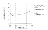
2) Evaluation of coefficient of thermal expansion The coefficient of thermal expansion at 700 ° C. was measured for each LSSC molded product sample of Example 3 obtained. FIG. 7 shows the change in the coefficient of thermal expansion with respect to the replacement ratio x / z of Sm of each LSSC molded product of Example 3.
SOFCでは、カソード層とカソード層に接合する相手部材との熱膨張係数が近いことが好ましい。カソード層は、セラミックス系材料で形成される電解質層、反応抑止層若しくは集電部材や、又は金属系材料で形成される集電部材等の相手部材に接合されると想定される。これらの相手部材に対して整合性が取れる熱膨張係数としては、実施例1,2同様に、11〜12×10−6(K−1)程度が、目安値として想定される(想定熱膨張係数)。図7のグラフより、700℃下において、実施例3の各LSSC成形体は、Smの置換比率x/zが0<x/z≦0.5の範囲で、比較例3のLSC成形体の熱膨張係数より小さくなり、想定熱膨張係数に近づいている効果が認められた。 In SOFC, it is preferable that the coefficient of thermal expansion of the cathode layer and the mating member bonded to the cathode layer are close to each other. It is assumed that the cathode layer is joined to an electrolyte layer, a reaction suppression layer or a current collector member made of a ceramic material, or a mating member such as a current collector member made of a metal material. As the coefficient of thermal expansion that can be consistent with these mating members, about 11 to 12 × 10-6 (K -1 ) is assumed as a guideline value (assumed thermal expansion) as in Examples 1 and 2. coefficient). From the graph of FIG. 7, at 700 ° C., each LSSC compact of Example 3 had a Sm substitution ratio x / z in the range of 0 <x / z ≦ 0.5, and the LSSC compact of Comparative Example 3 was used. The effect of becoming smaller than the coefficient of thermal expansion and approaching the assumed coefficient of thermal expansion was observed.
[コイン型セルの作製]
〈実施例4〉
実施例4のSOFCの出力特性を評価するために、以下の手順によってカソード材料にLSSCを用いたコイン型セルC(disk)を作製した。すなわち、(1)式〔Laz−xSmxSr1−zCoO3〕における異なるモル組成比xのLSSC粉末を含有する複数種類のカソード層用ペースト(カソード材料)を用いて、図9に示す各コイン型セルC(disk)を複数作製した。
(アノード層支持体前駆体の作製)
粒径約0.5μmの市販の酸化ニッケル(NiO)粉末と、粒径約0.5μmの8YSZ(Y2O3:8〔mol〕%)粉末と、を重量比で、6:4で混合して混合粉体を得た。このアノード極支持体材料の混合粉体と、溶剤としてキシレンと、有機結合材としてポリビニルブチラールと、気孔形成材としてアクリル樹脂と、可塑剤としてフタル酸エステルと、を重量比で、48〜58:24:8.5:5〜15:4.5の割合で加え、キシレン中に分散させ、ボールミルで混練してスラリーを作製した。このスラリーからドクタブレード法によってPETの基材シート上にシートを成形し、当該シートを乾燥させ、厚み0.5〜1.0mmのアノード層支持体前駆体を作製した。
[Creation of coin-shaped cell]
<Example 4>
In order to evaluate the output characteristics of the SOFC of Example 4, a coin-shaped cell C (disk) using LSSC as a cathode material was produced by the following procedure. That is, using a plurality of types of cathode layer pastes (cathode materials) containing LSSC powders having different molar composition ratios x in the formula (1) [La z-x Sm x Sr 1-z CoO 3], FIG. A plurality of each coin-shaped cell C (disk) shown was produced.
(Preparation of anode layer support precursor)
And commercially available nickel oxide (NiO) powder having a particle size of about 0.5 [mu] m, 8YSZ particle size of about 0.5μm (Y 2 O 3: 8 [mol]%) and powder, in a weight ratio of 6: mixed with 4 To obtain a mixed powder. The mixed powder of the anode electrode support material, xylene as a solvent, polyvinyl butyral as an organic binder, acrylic resin as a pore-forming material, and phthalate ester as a plasticizer are used in a weight ratio of 48 to 58: The mixture was added at a ratio of 24: 8.5: 5 to 15: 4.5, dispersed in xylene, and kneaded with a ball mill to prepare a slurry. A sheet was formed from this slurry on a PET base sheet by the doctor blade method, and the sheet was dried to prepare an anode layer support precursor having a thickness of 0.5 to 1.0 mm.
(アノード層用ペーストの作製)
アノード層支持体前駆体を作製したのと同じ酸化ニッケル(NiO)粉末と、同じ8YSZ粉末と、溶剤としてα−テルピネオールと、バインダとしてエチルセルロースと、を重量比で、48:32:18:2の割合で加えて混合し、十分混練してアノード層用ペーストを作製した。
(Preparation of paste for anode layer)
The same nickel oxide (NiO) powder from which the anode layer support precursor was prepared, the same 8YSZ powder, α-terpineol as a solvent, and ethyl cellulose as a binder were used in a weight ratio of 48:32:18: 2. The mixture was added in proportion and mixed, and kneaded well to prepare a paste for the anode layer.
(電解質層用ペーストの作製)
粒径約0.5μmの市販のYSZ(Y2O3:8〔mol〕%−ZrO2:92〔mol〕%)粉末と、溶剤としてテルピネオール系溶剤と、バインダとしてエチルセルロースと、を重量比で、65:31:4の割合で加えて混合し、十分混練して電解質層用ペーストを作製した。
(Preparation of paste for electrolyte layer)
Commercially available YSZ (Y 2 O 3 : 8 [mol]%-ZrO 2 : 92 [mol]%) powder having a particle size of about 0.5 μm, a terpineol solvent as a solvent, and ethyl cellulose as a binder in a weight ratio. , 65: 31: 4, and mixed, and sufficiently kneaded to prepare a paste for an electrolyte layer.
(反応抑止層用ペーストの作製)
粒径約0.5μmの市販の10GDC(Gd2O3:10〔mol〕%−CeO2:90〔mol〕%)粉末に、溶剤としてα−テルピネオールと、バインダとしてエチルセルロースと、を重量比で、65:31:4の割合で加えて混合し、十分混練して反応抑止層用ペーストを作製した。
(Preparation of paste for reaction suppression layer)
A commercially available 10 GDC (Gd 2 O 3 : 10 [mol]%-CeO 2 : 90 [mol]%) powder having a particle size of about 0.5 μm, α-terpineol as a solvent, and ethyl cellulose as a binder in a weight ratio. , 65: 31: 4, and mixed, and sufficiently kneaded to prepare a reaction inhibitory layer paste.
(カソード層用ペーストの作製)
カソード材料として組成が異なるLSSC原料粉末を含有する複数種類のカソード層用ペーストを、以下の方法で作製した。(1)式〔Laz−xSmxSr1−zCoO3〕において、z=0.5の場合のSmのモル組成比「x」が所定の範囲内(0<x≦0.36)にあるLSSC原料粉末を用いた。具体的には、実施例3の各LSSC成形体を作製したそれぞれの組成のLSSC原料粉末と同じ組成のLSSC粉末を用いた(表1参照)。所定のモル組成比xの各LSSC粉末に、溶剤としてα−テルピネオールと、バインダとしてエチルセルロースと、を重量比で、80:17:3の割合でそれぞれ加えて混合し、十分混練して複数種類のカソード層用ペーストを得た。
(Preparation of paste for cathode layer)
A plurality of types of cathode layer pastes containing LSSC raw material powders having different compositions as cathode materials were prepared by the following methods. In the formula (1) [La z-x Sm x Sr 1-z CoO 3 ], the molar composition ratio "x" of Sm when z = 0.5 is within a predetermined range (0 <x ≦ 0.36). The LSSC raw material powder in the above was used. Specifically, LSSC powder having the same composition as the LSSC raw material powder having the respective composition for producing each LSSC molded product of Example 3 was used (see Table 1). To each LSSC powder having a predetermined molar composition ratio x, α-terpineol as a solvent and ethyl cellulose as a binder are added and mixed at a weight ratio of 80:17: 3, and are sufficiently kneaded to form a plurality of types. A paste for the cathode layer was obtained.
(コイン型セルC(disk)の作製)
上記した異なるモル組成比のLSSC粉末を含有するそれぞれのカソード層用ペーストと、上記した他部材用のペースト等とを用いて、以下の方法により、カソード層を形成するカソード材料のみで異なる図9に示すコイン型セルC(disk)を複数作製した。
上記のアノード層支持体前駆体を用いて、その片側の表面上に同心円状に上記のアノード層用ペーストをスクリーン印刷して乾燥し、直径約30mm、厚み約10μmの円形薄膜状のアノード層前駆体を積層した。さらに、アノード層前駆体の表面上に同心円状に上記の電解質層用ペーストをスクリーン印刷して乾燥し、直径約30mm、厚み約10μmの円形薄膜状の電解質層前駆体を積層した。さらに、同様に、電解質層前駆体の表面上に同心円状に上記の反応抑止層用ペーストをスクリーン印刷して乾燥し、直径約15mm、厚み約5μmの円形薄膜状の反応抑止層前駆体を積層した後、直径約25mmの円板状に切り抜いた。アノード層支持体/アノード層/電解質層がほぼ同径で、反応抑止層のみ小径をなして同心円状に積層される積層体前駆体を得た。
(Creation of coin-shaped cell C (disk))
FIG. 9 shows that each cathode layer paste containing the above-mentioned LSSC powder having a different molar composition ratio and the above-mentioned paste for other members are used, and only the cathode material for forming the cathode layer is different by the following method. A plurality of coin-shaped cells C (disk) shown in the above were produced.
Using the above-mentioned anode layer support precursor, the above-mentioned anode layer paste is screen-printed concentrically on one side of the surface and dried, and a circular thin film-like anode layer precursor having a diameter of about 30 mm and a thickness of about 10 μm is dried. The body was laminated. Further, the above-mentioned electrolyte layer paste was screen-printed concentrically on the surface of the anode layer precursor and dried, and a circular thin film-shaped electrolyte layer precursor having a diameter of about 30 mm and a thickness of about 10 μm was laminated. Further, similarly, the above-mentioned reaction suppressing layer paste is screen-printed concentrically on the surface of the electrolyte layer precursor and dried, and a circular thin film-shaped reaction suppressing layer precursor having a diameter of about 15 mm and a thickness of about 5 μm is laminated. After that, it was cut out into a disk shape having a diameter of about 25 mm. A laminate precursor was obtained in which the anode layer support / anode layer / electrolyte layer had substantially the same diameter, and only the reaction suppression layer had a small diameter and were laminated concentrically.
次に、上記のアノード層支持体/アノード層/電解質層/反応抑止層の積層体前駆体を1350℃で3時間焼成した。アノード層支持体12、アノード層11、電解質層31及び反応抑止層32が、順に積層された円板状のハーフセル積層体を作製した。
Next, the laminate precursor of the anode layer support / anode layer / electrolyte layer / reaction suppression layer was calcined at 1350 ° C. for 3 hours. A disc-shaped half-cell laminate in which the
次に、上記のハーフセル積層体の反応抑止層32の表面上に同心円状にカソード層用ペーストをスクリーン印刷して乾燥し、直径約10mmのカソード層前駆体を積層した。ハーフセル積層体/カソード層の順に、小径をなして同心円状に積層される積層体前駆体を得た。
Next, the cathode layer paste was screen-printed concentrically on the surface of the
次に、上記のハーフセル積層体/カソード層の積層体前駆体を1000℃で2時間焼成した。図9に示すとおり、アノード層支持体12、アノード層11、電解質層31、反応抑止層32及びカソード層21が、順に積層されたコイン型セルC(disk)を作製した。コイン型セルC(disk)は、アノード層支持体12、アノード層11、電解質層31がほぼ同径をなし、反応抑止層32、カソード層21の順に小径をなし、これら各層が同心円状に積層され、アノード層11、電解質層31、反応抑止層32及びカソード層21全体で約50μmの厚みを有する円形の平板型構成を有する。
Next, the above-mentioned half-cell laminate / cathode layer laminate precursor was calcined at 1000 ° C. for 2 hours. As shown in FIG. 9, a coin-shaped cell C (disk) in which the
(比較例4)
(コイン型セルC(disk)の作製)
比較例3のz=0.5の場合のLSC〔La0.5Sr0.5CoO3〕粉末を用いて、実施例4と同じ製法で、同じ形状を有するコイン型セルC(disk)を作製した。
(Comparative Example 4)
(Creation of coin-shaped cell C (disk))
Using the LSC [La 0.5 Sr 0.5 CoO 3 ] powder in the case of z = 0.5 in Comparative Example 3, a coin-shaped cell C (disk) having the same shape was produced by the same manufacturing method as in Example 4. Made.
[セル電圧評価]
(発電試験)
実施例4及び比較例4に係るコイン型セルC(disk)を用いて、以下の条件にて発電試験を行い、各コイン型セルC(disk)のセル電圧を実測定した。
実施例4のコイン型セルC(disk)は、略円形平板型の全体形状を有する。コイン型セルC(disk)は、図9に示すとおり、アノード層支持体12、アノード層11、電解質層31がほぼ同径をなし、反応抑止層32、カソード層21の順に小径をなし、これら各層が図示において順に上方に同心円状に積層される構成を有している。
公知の発電試験装置を用いて、700℃の環境温度下で、アノード層支持体12の露出部に白金製のメッシュ状部材からなる電極体を接触させてアノード極側の集電を行い、同様に、カソード層21の表面に電極体を接触させてカソード極側の集電を行った。燃料ガスとしてH2を用い、酸化ガスとして空気を用い、それぞれ200(ml/min)の流量で流した。所定の電流密度0.2(A/cm2)における電極体間の電圧を測定した。
[Cell voltage evaluation]
(Power generation test)
Using the coin-type cell C (disk) according to Example 4 and Comparative Example 4, a power generation test was performed under the following conditions, and the cell voltage of each coin-type cell C (disk) was actually measured.
The coin-shaped cell C (disk) of the fourth embodiment has an overall shape of a substantially circular flat plate type. In the coin-shaped cell C (disk), as shown in FIG. 9, the
Using a known power generation test device, an electrode body made of a platinum mesh member is brought into contact with the exposed portion of the
(セル電圧:円筒型セル)
このように測定したコイン型セルC(disk)の電圧から、円筒型セルC(cyl)の電圧を推定した。具体的には、円筒型セルC(cyl)の伝送線モデル(等価回路)を用いて、発電試験で得られたコイン型セルC(disk)のセル電圧実測値に基づき、円筒型セルC(cyl)の出力電圧を求めるためのシミュレーションを行った。円筒型セルC(cyl)には所定の仮想集電部材(図示せず)が取り付けられているものと仮想して、上記のシミュレーション値から、仮想集電部材の集電損失分の電圧降下算出値を減算する補正を行い、円筒型セルC(cyl)の電圧を推定した。
円筒型セルC(cyl)は、図10に示すように、径方向に沿って内側から外側に向かって順に、コイン型セルC(disk)のアノード層支持体12、アノード層11、電解質層31、反応抑止層32、カソード層21の5層の各層に対応する、アノード層支持体120、アノード層110、電解質層310、反応抑止層320、カソード層210を有する。
(Cell voltage: Cylindrical cell)
The voltage of the cylindrical cell C (cyl) was estimated from the voltage of the coin-shaped cell C (disk) measured in this way. Specifically, using the transmission line model (equivalent circuit) of the cylindrical cell C (cyl), the cylindrical cell C (equivalent circuit) is based on the measured cell voltage of the coin cell C (disk) obtained in the power generation test. A simulation was performed to obtain the output voltage of cyl). Assuming that a predetermined virtual current collecting member (not shown) is attached to the cylindrical cell C (cyl), the voltage drop for the current collecting loss of the virtual current collecting member is calculated from the above simulation value. The voltage of the cylindrical cell C (cyl) was estimated by performing correction by subtracting the value.
As shown in FIG. 10, the cylindrical cell C (cyl) has the
円筒型セルC(cyl)は、軸方向に沿った所定長さ(例えばL=50mm)の電極長を有する。外部回路に接続される円筒型セルC(cyl)の集電部位は、アノード層110とカソード層210における軸方向に沿った一端部及び他端部にある。また、この伝送線モデルにおいてシミュレーションを行うために、各層を形成する材料の物性値として、既知の数値を与えた。その中で、カソード層210の電気伝導率としては、実施例3に係る各LSSC成形体で実測した数値を与えた。なお、カソード層210に接続した仮想カソード集電部材の電気伝導率としては、対応する実施例3に係る各LSSC成形体で実測した数値に基づき、30%の気孔率を有するものとして算出した数値を与えた。
The cylindrical cell C (cyl) has an electrode length of a predetermined length (for example, L = 50 mm) along the axial direction. The current collecting portions of the cylindrical cell C (cyl) connected to the external circuit are at one end and the other end along the axial direction in the
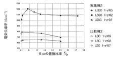
図8に、円筒型セルC(cyl)のセル電圧を示す。実施例4及び比較例4に係る各コイン型セルC(disk)の実測電圧値に基づいて算出した各円筒型セルC(cyl)の出力電圧と、LSSCのSmの置換比率x/zとの関係を表わすグラフを示した。
図8より、カソード層21のカソード材料としてLSSCを含有し、かつ、仮想カソード集電部材の導電性材料としてLSSCを用いると仮想した実施例4の各円筒型セルC(cyl)は、700℃下において、比較例4の円筒型セルC(cyl)に匹敵するセル電圧を示すことを確認できた。Smの置換比率x/zが0<x/z<0.72の範囲にある円筒型セルC(cyl)では、比較例4のセルと同様なセル電圧が得られており、評価することができた。特に、Smの置換比率x/zが0.08の近辺のLSSCを用いた円筒型セルC(cyl)では、比較例4の円筒型セルC(cyl)よりも大きなセル電圧が得られており、高評価することができた。
FIG. 8 shows the cell voltage of the cylindrical cell C (cyl). The output voltage of each cylindrical cell C (cyl) calculated based on the measured voltage value of each coin cell C (disk) according to Example 4 and Comparative Example 4 and the replacement ratio x / z of Sm of LSSC. A graph showing the relationship is shown.
From FIG. 8, each cylindrical cell C (cyl) of Example 4, which contains LSSC as the cathode material of the
[カソード材料の総合評価]
第二実施例においてLSSCをSOFCセルのカソード材料として用いた実施例3,4の評価結果を比較例と相対評価する形式で表1に示した。
[Comprehensive evaluation of cathode materials]
Table 1 shows the evaluation results of Examples 3 and 4 in which LSSC was used as the cathode material of the SOFC cell in the second example in a format for relative evaluation with the comparative example.

表1、および図6〜8から、総合的に以下のとおり判断できる。すなわち、Smのペロブスカイト型酸化物に対する置換比率x/zのとり得る範囲が0<x/z<0.72であれば、電気伝導率が大きく、熱膨張係数が適正値に近づき、比較例のLSCを用いる場合と比べて遜色ないセル電圧を得られるので好ましい。更に、置換比率x/zのとり得る範囲が0.08≦x/z≦0.5であれば、上記効果が得られることが明らかである点で特に好ましい。 From Table 1 and FIGS. 6 to 8, it can be judged comprehensively as follows. That is, if the possible range of the substitution ratio x / z of Sm with respect to the perovskite-type oxide is 0 <x / z <0.72, the electrical conductivity is large and the coefficient of thermal expansion approaches an appropriate value, and the comparative example It is preferable because a cell voltage comparable to that in the case of using LSC can be obtained. Further, when the possible range of the substitution ratio x / z is 0.08 ≦ x / z ≦ 0.5, it is particularly preferable in that it is clear that the above effect can be obtained.
また、SOFCセルの出力特性を評価するために、カソード層21の上に仮想カソード集電部材が積層され、カソード材料及び導電性材料がともにLSSCを含有する構成の円筒型セルC(cyl)を想定して検討を行ったが、本実施例は、当該構成に限定されない。少なくともカソード材料がLSSCを含有する構成のSOFCセルであっても、電気伝導率向上の効果を得ることができる。但し、SOFCセルは、異なるセラミックス同士や、金属−セラミックス等の異種材料の接合体として構成されるので、異なる材料の界面においては、絶縁性反応物が生じたり、成分元素の相互拡散が進み電極反応活性が阻害されたりする虞を内包している。カソード層とカソード層に接合されるカソード集電層ないし集電体とが、同じ材料であれば、このような障害の発生を抑制できるので好ましい。
Further, in order to evaluate the output characteristics of the SOFC cell, a cylindrical cell C (cyl) having a structure in which a virtual cathode current collector member is laminated on the
なお、LSCは、電気伝導率が大きく優れているものの、熱膨張係数が一般的な金属材料やセラミックス系材料よりも大きい。大きな電気伝導率と、他部材と同程度の熱膨張係数とを備えたカソード材料の出現が期待されている。本実施例は、このような問題を鑑みて行ったものであり、高温で動作する条件下で大きな電気伝導率を有し、他部材の熱膨張係数に近い熱膨張係数を有するカソード層を備えた燃料電池を提供することを目的としている。 Although LSC has a large electrical conductivity and is excellent, the coefficient of thermal expansion is larger than that of general metal materials and ceramic materials. The emergence of cathode materials with large electrical conductivity and a coefficient of thermal expansion comparable to that of other members is expected. This embodiment was carried out in view of such a problem, and includes a cathode layer having a large coefficient of electrical conductivity under conditions of operation at a high temperature and having a coefficient of thermal expansion close to the coefficient of thermal expansion of other members. The purpose is to provide a fuel cell.
以上、詳述したとおり、本発明のSOFC100(燃料電池)は、本実施形態又は本実施例に記載したペロブスカイト型酸化物を用いており、電解質層3と、電解質層3の一方側に設けられたカソード層2と、電解質層3の他方側に設けられたアノード層1と、カソード層2又はアノード層1の少なくとも一方に電気的に接続して電極反応する電子を集電し、又は単セルCないしSOFC100の外部に電気を取り出す集電体Eと、を備え、集電体Eを構成する集電部材52又はカソード層2の少なくとも一方が、一般式ABO3で示されるペロブスカイト型酸化物を導電性材料又はカソード材料として含有し、ペロブスカイト型酸化物が、AサイトにLa及びSrを配列し、かつ、BサイトにCoを配列し、Aサイトに配列されるLa及びSrのうち、一方のLaの一部がSmで置換され、Smのペロブスカイト型酸化物に対するモル組成比は、置換前のLaのペロブスカイト型酸化物に対するモル組成比より小さい、ペロブスカイト構造を有する。
As described in detail above, the SOFC100 (fuel cell) of the present invention uses the perovskite-type oxide described in the present embodiment or this embodiment, and is provided on one side of the
よって、導電性材料の電気伝導率が、従来材料のLaSrCoO3より大きくなることにより、集電部材52の電気抵抗に起因する電圧損失を低減することができ、SOFC100の出力特性を向上することができる。SOFC100は一般に単セルCを多数積層し、単セルCそれぞれを集電体Eを介して電気的に接続した状態で発電するので、電気抵抗が小さくなる効果が大きい。そのうえで、LaSmSrCoO3の熱膨張係数は、LaSrCoO3よりも低減し、金属材料やセラミックス系材料を始めとした他部材の熱膨張係数に近づく。つまり。LaSmSrCoO3の熱膨張係数がLaSrCoO3よりも小さいので、高温下(作動温度下)でのセラミックス系材料と金属材料との熱膨張係数の不一致に起因して、集電部材52と金属材料を主成分とするセパレータ層51とが剥離しようとするのを抑制できる。よって、接触抵抗を低減できるのでさらに燃料電池の出力特性を向上できる。
Therefore, since the electric conductivity of the conductive material is larger than that of the conventional material LaSrCoO 3 , the voltage loss due to the electric resistance of the current collecting
よって、第一実施例で述べた効果に加えて、カソード材料の電気伝導率が、従来材料のLaSrCoO3より大きくなる。LaSmSrCoO3は、LaSrCoO3と同様に酸素活性化触媒機能、酸素イオン導電性及び電子導電性を有している。そのうえで、LaSmSrCoO3の熱膨張係数がLaSrCoO3よりも小さいので、高温下(作動温度下)での他のセラミックス系材料との、又は金属材料との熱膨張係数の不一致に起因して、カソード層2と金属材料を主成分とするセパレータ層51とが、若しくはカソード層2とセラミックス系材料を主成分とする電解質層3や集電体Eとが、剥離しようとするのを抑制できる。従来公知のLaSrCoO3の熱膨張係数は、SOFC用として一般的に用いられる金属やセラミックスの他材料と比較して相当大きく、熱膨張係数の整合性を取るのが難しくなる傾向があったので、導電性能を活用しながら熱膨張係数が低減される効果が際立つ。よって、接触抵抗を低減できるのでさらに燃料電池の出力特性を向上できる。
なお、上述した実施例では、カソード材料として好ましいLaSrCoO3の組成について、Smの置換比率x/zをパラメータとする好ましい範囲について具体的に説明したが、Smのモル組成比xをパラメータとして用いても同様の好ましい範囲を有することができる。
Therefore, in addition to the effect described in the first embodiment, the electric conductivity of the cathode material becomes larger than that of the conventional material LaSrCoO 3. Like LaSrCoO 3 , LaSmSrCoO 3 has an oxygen activation catalyst function, oxygen ion conductivity, and electron conductivity. Sonouede, the thermal expansion coefficient of the LaSmSrCoO 3 is smaller than the LaSrCoO 3, with other ceramic material at a high temperature (under operating temperature), or due to mismatch in thermal expansion coefficient between the metallic material, the cathode layer It is possible to prevent the 2 and the separator layer 51 containing a metal material as a main component, or the
In the embodiment described above, the composition of preferred LaSrCoO 3 as the cathode material has been specifically described with reference to a preferred range of the substitution ratio x / z of the Sm as a parameter, with a molar composition ratio x of the Sm as a parameter Can have a similar preferred range.
さらに、LaSmSrCoO3を導電性材料及びカソード材料とする仮想集電部材及びカソード層210を備えた円筒型セルC(cyl)は、従来材料のLaSrCoO3を導電性材料及びカソード材料とするものよりも、出力特性を高めることができる。また、LaSmSrCoO3を導電性材料及びカソード材料とする仮想集電部材及びカソード層210を備えた円筒型セルC(cyl)は、カソード層とカソード層に接合される(仮想)カソード集電部材とが、同じ材料なので、上述した電極反応活性が阻害される障害の発生を抑制することができ、SOFCセルの出力特性の劣化を抑制することができる。
Further, the cylindrical cell C (cyl) provided with the virtual current collector member using LaSmSrCoO 3 as the conductive material and the cathode material and the cathode layer 210 is more than the conventional material LaSrCoO 3 used as the conductive material and the cathode material. , The output characteristics can be improved. Further, the cylindrical cell C (cyl) provided with the virtual current collecting member using LaSmSrCoO 3 as the conductive material and the cathode material and the
また、LaSmSrCoO3の熱膨張係数がLaSrCoO3よりも小さいので、セパレータ層51、集電体E(集電部材52)、電解質層3等の電池部材との熱膨張係数の不一致を低減することで、割れ欠けが生じにくくなるので信頼性を高められる。
Further, since the thermal expansion coefficient of the LaSmSrCoO 3 is smaller than the LaSrCoO 3, the separator layer 51, the collector E (current collecting member 52), by reducing the mismatch of thermal expansion coefficient between the
1,11,110…アノード層、2,21,210…カソード層、3,31,310…電解質層、51…セパレータ層、52…集電部材、100…SOFC(燃料電池)、C…単セル、C(disk)…コイン型セル(単セル)、C(cyl)…円筒型セル(単セル)、E…集電体。 1,11,110 ... Anode layer, 2,21,210 ... Cathode layer, 3,31,310 ... Electrolyte layer, 51 ... Separator layer, 52 ... Current collector, 100 ... SOFC (fuel cell), C ... Single cell , C (disk) ... Coin-type cell (single cell), C (cyl) ... Cylindrical cell (single cell), E ... Current collector.
Claims (3)
前記電解質層の一方側に設けられたカソード層と、
前記電解質層の他方側に設けられたアノード層と、
前記カソード層又は前記アノード層の少なくとも一方に電気的に接続して電子を集電し、又は燃料電池の外部に電気を取り出す集電部材と、
を備え、
前記集電部材又は前記カソード層の少なくとも一方が、一般式ABO3で示されるペロブスカイト型酸化物を材料として含有し、
前記ペロブスカイト型酸化物が、
AサイトにLa及びSrを配列し、かつ、BサイトにCoを配列し、
前記Aサイトに配列されるLa及びSrのうち、一方のLaの一部がSmで置換され、
Smの前記ペロブスカイト型酸化物に対するモル組成比は、置換前のLaの前記ペロブスカイト型酸化物に対するモル組成比よりも小さい、
ペロブスカイト構造を有する燃料電池。 With the electrolyte layer,
A cathode layer provided on one side of the electrolyte layer and
An anode layer provided on the other side of the electrolyte layer and
A current collecting member that is electrically connected to at least one of the cathode layer or the anode layer to collect electrons or to take out electricity to the outside of the fuel cell.
With
At least one of the current collector member and the cathode layer contains a perovskite-type oxide represented by the general formula ABO 3 as a material.
The perovskite-type oxide
La and Sr are arranged at the A site, and Co is arranged at the B site.
Of the La and Sr arranged at the A site, a part of one La is replaced with Sm.
The molar composition ratio of Sm to the perovskite oxide is smaller than the molar composition ratio of La before substitution to the perovskite oxide.
A fuel cell having a perovskite structure.
Laz−xSmxSr1−zCoO3 (1)
前記式(1)において、置換前のLaの前記ペロブスカイト型酸化物中のモル組成比zに対するSmの前記ペロブスカイト型酸化物中のモル組成比xの比率を示すx/zが、0.01≦x/z<0.5の範囲にあり、
Srの前記ペロブスカイト型酸化物中のモル組成比(1−z)が、0.2≦1−z≦0.7の範囲にある請求項1に記載の燃料電池。 The material contained in the current collector is the perovskite-type oxide having a composition represented by the following formula (1).
La z-x Sm x Sr 1-z CoO 3 (1)
In the formula (1), x / z indicating the ratio of the molar composition ratio x of Sm in the perovskite-type oxide to the molar composition ratio z of La in the perovskite-type oxide before substitution is 0.01 ≦. In the range of x / z <0.5,
The fuel cell according to claim 1, wherein the molar composition ratio (1-z) of Sr in the perovskite-type oxide is in the range of 0.2 ≦ 1-z ≦ 0.7.
Priority Applications (1)
| Application Number | Priority Date | Filing Date | Title |
|---|---|---|---|
| EP17158136.6A EP3211703B1 (en) | 2016-02-29 | 2017-02-27 | Fuel cell |
Applications Claiming Priority (2)
| Application Number | Priority Date | Filing Date | Title |
|---|---|---|---|
| JP2016037201 | 2016-02-29 | ||
| JP2016037201 | 2016-02-29 |
Publications (2)
| Publication Number | Publication Date |
|---|---|
| JP2017157553A JP2017157553A (en) | 2017-09-07 |
| JP6836156B2 true JP6836156B2 (en) | 2021-02-24 |
Family
ID=59810732
Family Applications (1)
| Application Number | Title | Priority Date | Filing Date |
|---|---|---|---|
| JP2017023514A Active JP6836156B2 (en) | 2016-02-29 | 2017-02-10 | Fuel cell |
Country Status (1)
| Country | Link |
|---|---|
| JP (1) | JP6836156B2 (en) |
Families Citing this family (2)
| Publication number | Priority date | Publication date | Assignee | Title |
|---|---|---|---|---|
| KR102004250B1 (en) | 2017-11-27 | 2019-07-26 | 한국에너지기술연구원 | Method of fabricating cathode, cathode and solid oxide fuel cell having the same |
| KR102261142B1 (en) | 2018-10-31 | 2021-06-07 | 한국에너지기술연구원 | SOFC cathodes using electrochemical technique and its manufacturing method |
-
2017
- 2017-02-10 JP JP2017023514A patent/JP6836156B2/en active Active
Also Published As
| Publication number | Publication date |
|---|---|
| JP2017157553A (en) | 2017-09-07 |
Similar Documents
| Publication | Publication Date | Title |
|---|---|---|
| US7553573B2 (en) | Solid state electrochemical composite | |
| JP5225336B2 (en) | Fuel cell and fuel cell | |
| JP4928642B1 (en) | Solid oxide fuel cell | |
| JP5209359B2 (en) | Solid oxide fuel cell | |
| JP5368139B2 (en) | Solid oxide fuel cell | |
| JP6370696B2 (en) | Cell structure, electrolyte membrane-electrode assembly, and fuel cell | |
| JP6695677B2 (en) | Electrode material for solid oxide fuel cell and solid oxide fuel cell using the same | |
| JP2012104407A (en) | Electrolyte-electrode assembly, and method for manufacturing the same | |
| JP6275561B2 (en) | BODY, BODY MANUFACTURING METHOD, SOLID OXIDE FUEL CELL, AND WATER ELECTROLYTIC DEVICE | |
| JP2013197036A (en) | Fuel cell and method for manufacturing laminated sintered body | |
| JP2006073230A (en) | Fuel cell | |
| JP5336207B2 (en) | Solid oxide fuel cell | |
| JP2011119178A (en) | Solid oxide fuel cell | |
| JP6836156B2 (en) | Fuel cell | |
| US20050250000A1 (en) | Novel composite solid oxide fuel cell anode based on ceria and strontium titanate | |
| JP4828104B2 (en) | Fuel cell | |
| KR102111859B1 (en) | Solid oxide fuel cell and a battery module comprising the same | |
| EP3211703B1 (en) | Fuel cell | |
| JP5313518B2 (en) | Solid electrolyte fuel cell | |
| JP5133787B2 (en) | Solid oxide fuel cell | |
| JP5350893B2 (en) | Solid oxide fuel cell | |
| JP4849774B2 (en) | Solid electrolyte fuel cell and solid electrolyte fuel cell | |
| JP2012099322A (en) | Solid oxide fuel cell | |
| JP5117834B2 (en) | Solid oxide fuel cell | |
| JP4579527B2 (en) | Fuel cell, fuel cell and method for producing fuel cell |
Legal Events
| Date | Code | Title | Description |
|---|---|---|---|
| A621 | Written request for application examination |
Free format text: JAPANESE INTERMEDIATE CODE: A621 Effective date: 20200110 |
|
| A977 | Report on retrieval |
Free format text: JAPANESE INTERMEDIATE CODE: A971007 Effective date: 20201224 |
|
| TRDD | Decision of grant or rejection written | ||
| A01 | Written decision to grant a patent or to grant a registration (utility model) |
Free format text: JAPANESE INTERMEDIATE CODE: A01 Effective date: 20210106 |
|
| A61 | First payment of annual fees (during grant procedure) |
Free format text: JAPANESE INTERMEDIATE CODE: A61 Effective date: 20210119 |
|
| R151 | Written notification of patent or utility model registration |
Ref document number: 6836156 Country of ref document: JP Free format text: JAPANESE INTERMEDIATE CODE: R151 |