JP6834143B2 - Decapper - Google Patents
Decapper Download PDFInfo
- Publication number
- JP6834143B2 JP6834143B2 JP2016031229A JP2016031229A JP6834143B2 JP 6834143 B2 JP6834143 B2 JP 6834143B2 JP 2016031229 A JP2016031229 A JP 2016031229A JP 2016031229 A JP2016031229 A JP 2016031229A JP 6834143 B2 JP6834143 B2 JP 6834143B2
- Authority
- JP
- Japan
- Prior art keywords
- container
- cap
- holding
- moving table
- filling
- Prior art date
- Legal status (The legal status is an assumption and is not a legal conclusion. Google has not performed a legal analysis and makes no representation as to the accuracy of the status listed.)
- Active
Links
Images


Landscapes
- Devices For Opening Bottles Or Cans (AREA)
Description
本発明は、容器に巻き締められているキャップを取外すデキャッパに関する。 The present invention relates to a decapper that removes a cap that is wrapped around a container.
従来、例えば充填機に対して供給される空の容器内にゴミが入るのを防止するために、容器の開口をキャップによって閉塞した状態で搬送する充填処理システムが知られている。このような充填システムでは、充填工程の直前に容器からキャップを取外すためにデキャッパが設けられ、デキャッパでは、容器が供回りしないように保持してキャップが回転される。この回転に伴ってキャップは容器に対して上昇するが、キャップの上昇速度はキャップのネジの傾斜角度に応じて定まり、キャップの上昇速度がネジの傾斜角度に正確に対応していないと、特にネジの強度が低い場合等においてネジが損傷するおそれがある。そこで、この問題を解決することを目的として特許文献1に開示された構成が提案されている。 Conventionally, for example, in order to prevent dust from entering an empty container supplied to a filling machine, a filling processing system in which the opening of the container is closed by a cap is known. In such a filling system, a decapper is provided to remove the cap from the container immediately before the filling process, and the decapper holds the container so that it does not rotate and rotates the cap. With this rotation, the cap rises with respect to the container, but the rising speed of the cap is determined by the tilt angle of the screw of the cap, especially if the rising speed of the cap does not accurately correspond to the tilt angle of the screw. If the strength of the screw is low, the screw may be damaged. Therefore, a configuration disclosed in Patent Document 1 has been proposed for the purpose of solving this problem.
しかしながら特許文献1の構成はサーボモータを用いて複雑な制御を必要としており、キャップを把持するチャックの上昇速度と、キャップの回転による上昇速度との関係を高精度に設定しなければならないという問題があった。 However, the configuration of Patent Document 1 requires complicated control using a servomotor, and there is a problem that the relationship between the ascending speed of the chuck holding the cap and the ascending speed due to the rotation of the cap must be set with high accuracy. was there.
本発明は、簡単な構成により、容器またはキャップのネジが損傷することなくスムーズにキャップを容器から取外すことのできるデキャッパを提供することを目的としている。 An object of the present invention is to provide a decapper capable of smoothly removing a cap from a container without damaging the screw of the container or the cap by a simple structure.
本発明は、容器を、軸心周りに回転せず、かつ昇降自在な状態に支持する容器支持手段と、キャップを保持するキャップ保持手段と、キャップ保持手段を容器に対して回転させる回転手段と、キャップ保持手段を、容器支持手段に対して相対的に昇降させる昇降手段とを備え、キャップ保持手段によりキャップを保持し、かつ昇降手段が容器支持手段に対して容器を相対的に所定量上昇させた状態で、容器が容器支持手段により支持されて、回転手段がキャップ保持手段を回転させることにより、キャップが回転されて容器からキャップが取外されるのに伴い、容器が自重により軸心に沿って容器支持手段に対し相対的に下降することを特徴としている。 INDUSTRIAL APPLICABILITY The present invention includes a container supporting means for supporting a container so as to be able to move up and down without rotating around an axis, a cap holding means for holding a cap, and a rotating means for rotating the cap holding means with respect to the container. The cap holding means is provided with an elevating means for raising and lowering the container relative to the container supporting means, the cap is held by the cap holding means, and the elevating means raises the container by a predetermined amount relative to the container supporting means. axis in a state of being, the container is supported by the container supporting means, by rotating means rotates the cap holding means, the cap is due to the rotated with the container's cap Ru removed, the container by its own weight It is characterized in that it descends relative to the container supporting means along the above.
容器支持手段は例えば、容器が嵌合される保持穴を有する板状部材を有し、保持穴に、容器の外周面に形成されて軸心方向に延びる突起が係合する凹部が形成される。 The container supporting means has, for example, a plate-shaped member having a holding hole into which the container is fitted, and the holding hole is formed with a recess formed on the outer peripheral surface of the container and in which a protrusion extending in the axial direction is engaged. ..
本発明によれば、簡単な構成により、容器またはキャップのネジが損傷することなくスムーズにキャップを容器から取外すことのできるデキャッパを得ることができる。 According to the present invention, it is possible to obtain a decapper capable of smoothly removing the cap from the container without damaging the screw of the container or the cap with a simple configuration.
以下、図示された実施形態を参照して本発明を説明する。
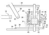
図1、2において、左端は冷凍保存容器(セラムチューブ)Aに対するデキャッピングとキャッピングを行うための施栓位置であり、施栓装置(デキャッパ)10が設けられる。施栓位置の右側は容器Aに対する内容物(例えば細胞の混濁液)を充填するための充填位置であり、充填装置20が設けられる。移動テーブル30が施栓位置と充填位置の間を往復移動する間に、1列の容器Aに対する分注が行われる。この移動方向すなわち図1、2の左右方向をX方向(第1の方向)と定義する。また図1、2において、右端は充填処理等を行う対象の容器Aの列を切替える作業を行うための切替え位置であり、移動テーブル30は、切替え位置に定められている間に、X方向に直交するY方向(第2の方向)に移動可能である。
Hereinafter, the present invention will be described with reference to the illustrated embodiments.
In FIGS. 1 and 2, the left end is a plugging position for decapping and capping the frozen storage container (serum tube) A, and a plugging device (decapper) 10 is provided. The right side of the plugging position is a filling position for filling the contents (for example, cell turbid liquid) with respect to the container A, and the
移動テーブル30はテーブル支持部材31の上に固定され、移動テーブル30の上には、複数の容器Aを保持する容器スタンド32が取付けられる。本実施形態では、容器スタンド32には容器Aが6×5の配列で直立整列される。すなわち容器Aは容器スタンド32において、X方向に6個整列され、Y方向に5列整列される。テーブル支持部材31はY方向に延びるYレール33の上に移動自在に支持され、Yレール33はX方向に延びる一対のXレール34の上に移動自在に支持される。
The moving table 30 is fixed on the
一方のXレール34の端部近傍には、Yレール33をXレール34に沿って移動させるためのサーボモータ35が設けられる。Xレール34の施栓位置側にはプーリ36が設けられ、このプーリ36とサーボモータ35の出力軸37とには無端状ベルト38が掛け回され、無端状ベルト38はYレール33に連結される。したがってサーボモータ35が駆動されることにより、Yレール33とテーブル支持部材31と移動テーブル30がX方向に沿って、施栓位置と充填位置の間において往復移動し、また切替え位置に移動される。
A
図2に示されるように、Yレール33の左側には位置決めプレート40が設けられ、右側には被押圧部材41が設けられる。位置決めプレート40と被押圧部材41はYレール33に平行に延び、連結部材42、43によって一体的に連結される。連結部材42、43は図示しない固定部材を介してYレール33に連結されており、したがって移動テーブル30、テーブル支持部材31、Yレール33、位置決めプレート40、被押圧部材41は、Xレール34に沿って一体的に移動する。
As shown in FIG. 2, a
位置決めプレート40には、Y方向に沿って一定間隔毎に、位置決め穴44が穿設される。位置決め穴44には、テーブル支持部材31の前方壁面から突出するポジショナー45が嵌合可能であり、この嵌合によってテーブル支持部材31と移動テーブル30のY方向の位置が定められる。
Positioning
切替え位置にはテーブル支持部材31をYレール33に沿って移動させるためのサーボモータ46が設けられる。サーボモータ46の出力軸にはアーム47が水平面内に揺動自在に連結され、アーム47の揺動端に設けられたローラ48は、テーブル支持部材31の後方壁面から突出する一対の係合プレート49の間に係合可能である。すなわち、アーム47が揺動することにより、ローラ48を介して、テーブル支持部材31と移動テーブル30がY方向に変位する。
A
また切替え位置には、被押圧部材41を充填位置側(図2の左方向)に押圧するプッシャ50が設けられる。プッシャ50は移動テーブル30が切替え位置に定められているとき、被押圧部材41を押圧して、位置決めプレート40の位置決め穴44をポジショナー45から解放する。すなわち、移動テーブル30が施栓位置と充填位置の間において往復移動する間、ポジショナー45が位置決め穴44に挿入されて、移動テーブル30のY方向の位置決めがされているが、切替え位置に移送されて被押圧部材41がプッシャ50に当接すると、プッシャ50が被押圧部材41を所定量だけ押し、これにより連結部材42、43を介して位置決めプレート40が施栓位置側に変位し、位置決め穴44がポジショナー45から外れる。これによりテーブル支持部材31はY方向に移動可能になる。
Further, at the switching position, a
図3を参照して施栓装置10の構成を説明する。施栓装置10の本体11には外側筒状部材12が設けられる。外側筒状部材12は本体11の下面から鉛直方向に延び、その中に設けられた内側筒状部材13は外側筒状部材12から下方に突出する。内側筒状部材13の下端には、容器Aの開口部に対してデキャッピングおよびキャッピングを行うためのチャック(キャップ保持手段)14が設けられる。チャック14はバキュームとゴムの摩擦力によってキャップCを保持するように構成されており、バキュームは、図示しない負圧源から、内側筒状部材13の軸心部分に形成されたバキューム通路15を介してチャック14内に導かれる。
The configuration of the
内側筒状部材13は外側筒状部材12に対して、軸心周りに回転自在であり、内側筒状部材13の上端は、本体11内に設けられたサーボモータ(回転手段)16の出力軸に連結される。また内側筒状部材13は外側筒状部材12に対して昇降可能である。この昇降可能な量は、上側筒状部材12と内側筒状部材13の間に設けられたバネ(図示せず)が撓む範囲である。例えばキャッピング時、チャック14がキャップCを保持して容器Aの開口部に被せた状態で、サーボモータ16がキャップCを容器Aに対して回転させると、内側筒状部材13とチャック14はバネによって下方へ付勢され、キャップCとともに徐々に下降する。なおデキャッピング時の動作については後述する。
The inner
本体11はエアシリンダ17によって昇降駆動され、施栓装置10の非作動時、チャック14が容器Aに干渉しないよう、上昇位置に定められる。これに対してデキャッピングあるいはキャッピングを行うとき、本体11は下降し、チャック14は容器Aの上端部に近接する。
The
容器Aは上述したように、例えば6×5の配列で容器スタンド32に直立状態で支持される。図3、4に示すように、容器スタンド32には容器Aを保持する板状の第1および第2の容器保持部材51a、51bが設けられる。第1の容器保持部材(容器支持手段)51aは容器Aが嵌合される保持穴52を有し、保持穴52には凹部53が形成される。凹部53には、容器Aの外周面に形成されて軸心方向に延びる複数の突起Bが係合する。したがって容器Aは容器保持部材51aにより、軸心周りに回転しない状態で昇降可能に保持される。一方、第2の容器保持部材51bは第1の容器保持部材51aの上方に設けられ、容器Aが嵌合される支持穴(図示せず)が形成されるが、この支持穴には、凹部53のような突起Bが係合する凹部は形成されない。
As described above, the container A is supported upright on the container stand 32 in an arrangement of, for example, 6 × 5. As shown in FIGS. 3 and 4, the
図5は施栓装置10によるデキャッピングを示している。容器Aにおいて、突起Bは下部の外周面に形成されており、周方向に沿って等間隔に設けられ、図4から理解されるように本実施形態では8本である。突起Bは、容器Aが容器スタンド32に置かれた状態(図5(a))において、少なくとも容器保持部材51aに係合する位置から容器Aの底部まで延びている。したがって容器Aがチャック14によって所定量だけ持ち上げられた状態において、突起Bは保持穴52の凹部53に係合している(図5(b))。
FIG. 5 shows decapping by the plugging
デキャッピングは次のようにして行われる。
容器Aは空の状態でキャップCによって閉鎖され、容器保持部材51aの各保持穴52に嵌合装着されて容器スタンド32にセットされる。容器スタンド32が移動テーブル30により施栓位置へ搬送されてくると、施栓装置10のチャック14がエアシリンダ17の作用によって下降し、容器スタンド32上の1つのキャップCに係合する(図5(a))。次にチャック14がエアシリンダ17によって、容器保持部材51aに対して上昇させられ、これにより容器Aは、突起Bの下端部が保持穴52の凹部53から離脱しない程度に持ち上げられる(図5(b))。すなわちエアシリンダ17はチャック14を昇降させる昇降手段を構成する。
Decapping is done as follows.
The container A is closed by the cap C in an empty state, fitted to each holding
このように容器Aが容器保持部材51aに対して所定量上昇され、容器スタンド32の底板上面39と容器Aの下端とを隔離して間隙を形成した状態で、サーボモータ16がチャック14を回転させると、キャップCが容器Aに対して回転し、容器Aは突起Bと凹部53の係合によって、供回りすることなく、キャップCが取外されるのに伴い、自重により軸心に沿って相対的に下降する。間隙GはキャップCを容器Aから離脱させたときの容器移動量よりも大きな量に設定され、キャップCが取外された容器Aは再び容器スタンド32に載置される(図5(c))。なお取外されたキャップCは、チャック14によって保持された状態のまま待機する。
In this way, the container A is raised by a predetermined amount with respect to the
再び図1を参照して充填装置20の構成を説明する。充填装置20の本体21には充填ノズル22が設けられる。充填ノズル22は本体21の下面から鉛直方向に延び、充填ノズル22と施栓装置10のチャック14とを結んだ線はX方向に一致する(図2参照)。充填ノズル22には、タンク23に貯留された細胞等の懸濁液がチューブポンプ24を介して供給される。タンク23は支持台25に設けられたタンク揺動機構26に取付けられ、一定の揺動速度で揺動される。これは細胞等がタンク23の底部に溜まるのを防止するためである
The configuration of the filling
図6を参照して、本実施形態のデキャッパを備えた分注装置の作用を説明する。
上述したように、容器Aは空の状態でキャップCによって閉鎖され、容器スタンド32に載置されて移動テーブル30により施栓位置まで搬送される。まず、X方向に並ぶ容器Aの列において最も施栓位置に近い側にある第1の容器A1に施栓装置10のチャック14が下降して接近し、第1の容器A1に対するデキャッピングが行われる(符号(a))。次いで移動テーブル30はX方向に移動し、第1の容器A1が充填装置20の充填ノズル22の直下に来た位置で停止する(符号(b))。第1の容器A2に対する内容物(細胞の懸濁液)の充填が完了すると、移動テーブル30は施栓位置へ向かって移動し、第1の容器A1がチャック14の直下に来た位置で停止する(符号(c))。この位置において第1の容器A1に対するキャッピングが行われる。すなわち、符号(a)で示す工程において取外されてチャック14に保持されたキャップCが再び第1の容器A1に装着される。
The operation of the dispensing device including the decapper of the present embodiment will be described with reference to FIG.
As described above, the container A is closed by the cap C in an empty state, placed on the
次に移動テーブル30は、第1の容器A1に対してX方向に隣接する第2の容器A2がチャック14の直下に来るように移動し、その位置において停止する(符号(d))。この状態で、第2の容器A2に対してチャック14が下降して接近し、第2の容器A2に対するデキャッピングが行われる(符号(d))。そして、第1の容器A1の場合と同様に、移動テーブル30がX方向に移動し、充填位置において第2の容器A2に対して充填処理が行われ(符号(e))、その後、施栓位置において第2の容器A2に対するデキャッピングが行われる(符号(f))。
Next, the moving table 30 moves so that the second container A2 adjacent to the first container A1 in the X direction comes directly under the
このようにして移動テーブル30が施栓位置と充填位置の間を往復移動する間に、X方向に1列に並ぶ6個の容器A1〜A6に対する分注が行われると、移動テーブル30は切替え位置まで移送され、切替え位置においてY方向に移動される。切替え位置では、図7を参照して後述するように、テーブル支持部材31と移動テーブル30が容器の1列分だけY方向に変位する(符号(g))。そして移動テーブル30は再び施栓位置へ移送され、2列目の容器A7に対するデキャッピングが行われる(符号(h))。以下同様にして2列目の全ての容器に対する充填処理等が行われた後、他の列の容器に対する充填処理が行われ、容器スタンド32は次の工程に搬送される。
While the moving table 30 reciprocates between the plugging position and the filling position in this way, when dispensing is performed for the six containers A1 to A6 arranged in a row in the X direction, the moving table 30 is moved to the switching position. Is transferred to, and is moved in the Y direction at the switching position. At the switching position, as will be described later with reference to FIG. 7, the
図7を参照して、切替え位置における移動テーブル30のY方向への移動について説明する。図7(a)は、図中最も上に位置する容器列D1に対する充填処理が完了して、移動テーブル30が切替え位置に定められた状態を示す。移動テーブル30が切替え位置まで移動されるのに先立ち、アーム47のローラ48は一対の係合プレート49の間に対応した位置に定められている。したがって移動テーブル30は切換え位置において、被押圧部材41がプッシャ50に当接し、かつ一対の係合プレート49の間にローラ48が係合した状態で停止する。この状態で、プッシャ50が被押圧部材41を所定量だけ押し、これにより位置決めプレート40が施栓位置側に変位して位置決め穴44がポジショナー45から外れる。
The movement of the movement table 30 in the Y direction at the switching position will be described with reference to FIG. 7. FIG. 7A shows a state in which the moving table 30 is set to the switching position after the filling process for the container row D1 located at the top in the figure is completed. Prior to the moving table 30 being moved to the switching position, the
次いでサーボモータ46が駆動され、アーム47が揺動する。これにより移動テーブル30は、図の上方に移動し、容器列D1に隣り合う容器列D2がチャック14と充填ノズル22を結んだ線上に位置するような位置に定められる。次いでサーボモータ35が駆動されることにより、Yレール33とテーブル支持部材31と移動テーブル30がX方向に沿って施栓位置の方向へ移動し始め、これによりポジショナー45が位置決めプレート40の位置決め穴44内に挿入され、位置決めプレート40と被押圧部材41も移動テーブル30と共に施栓位置の方向へ移動する。また、これにより一対の係合プレート49がローラ48から外れる。
Next, the
以上のように本実施形態では、移動テーブル30はキャップCを装着された複数の容器AをX方向およびY方向に沿って整列した状態で保持する。そして、サーボモータ35は、所定の列の容器に対して、施栓装置10によってデキャッピングされた後、充填装置20によって内容物が充填され、施栓装置10によってキャッピングされるように、移動テーブル30を施栓位置と充填位置の間において往復移動させる。この往復移動において、サーボモータ35は所定の容器(例えば容器A1)に対して施栓装置10がキャッピングを行った後、その容器とは異なる容器(例えば容器A2)に対してデキャッピングを行なうように、移動テーブル30を移動させる。
As described above, in the present embodiment, the moving table 30 holds a plurality of containers A to which the caps C are attached in a state of being aligned along the X direction and the Y direction. Then, the
したがって本実施形態によれば、移動テーブル30に供給される複数の容器に対して、デキャッピング、充填、キャッピングを連続的に行うことができ、迅速かつ安定した品質で分注作業を行うことができる。またデキャッピングにおいて、容器を持ち上げた状態でキャップを回転させるように構成したことにより、容器はキャップの回転に伴って自然に下降するので、容器またはキャップのネジに過大な力が作用することはなく、ネジが損傷するおそれはない。 Therefore, according to the present embodiment, decapping, filling, and capping can be continuously performed on a plurality of containers supplied to the moving table 30, and dispensing work can be performed quickly and with stable quality. it can. Also, in decapping, by configuring the cap to rotate while the container is lifted, the container naturally descends as the cap rotates, so excessive force may act on the container or cap screws. There is no risk of screw damage.
なお上記実施形態では、デキャッピング、充填、キャッピングから成る分注動作を1本の容器毎に行っているが、複数本の容器に対して同時に分注動作を行うように構成することもできる。 In the above embodiment, the dispensing operation including decapping, filling, and capping is performed for each container, but it can also be configured to perform the dispensing operation for a plurality of containers at the same time.
また移動テーブル30については、従来公知のXYテーブルを採用してもよい。 Further, as the moving table 30, a conventionally known XY table may be adopted.
さらに、上記実施形態では、容器を持ち上げた状態でデキャッピングしているが、容器スタンド32または移動テーブル30を下降させた状態でデキャッピングすることも可能である。また上記実施形態では、デキャッピングの開始時に、チャック14が下降してキャップCに係合するが、これに替えて、容器を上昇させることによりキャップCをチャック14に係合させてもよい。
Further, in the above embodiment, the container is decapped while it is lifted, but it is also possible to decap it while the container stand 32 or the moving table 30 is lowered. Further, in the above embodiment, the
10 施栓装置(デキャッパ)
14 チャック(キャップ保持手段)
16 サーボモータ(回転手段)
17 エアシリンダ(昇降手段)
51a 第1の容器保持部材(容器支持手段)
A 容器
C キャップ
10 Plug device (decapper)
14 Chuck (cap holding means)
16 Servo motor (rotation means)
17 Air cylinder (elevating means)
51a First container holding member (container supporting means)
A container C cap
Claims (2)
キャップを保持するキャップ保持手段と、
前記キャップ保持手段を前記容器に対して回転させる回転手段と、
前記キャップ保持手段を、前記容器支持手段に対して相対的に昇降させる昇降手段とを備え、
前記キャップ保持手段により前記キャップを保持し、かつ前記昇降手段が前記容器支持手段に対して前記容器を相対的に所定量上昇させた状態で、前記容器が前記容器支持手段により支持されて、前記回転手段が前記キャップ保持手段を回転させることにより、キャップが回転されて前記容器からキャップが取外されるのに伴い、前記容器が自重により軸心に沿って前記容器支持手段に対し相対的に下降することを特徴とするデキャッパ。 A container support means that supports the container so that it can be raised and lowered without rotating around the axis.
Cap holding means to hold the cap and
A rotating means for rotating the cap holding means with respect to the container, and
A means for raising and lowering the cap holding means relative to the container supporting means is provided.
The container is supported by the container supporting means in a state where the cap is held by the cap holding means and the container is raised by a predetermined amount relative to the container supporting means. by rotating means rotates the said cap retaining means, the cap is accompanied from the container is rotated in cap Ru removed relatively the container relative to the container support means along the axis by its own weight A decapper characterized by descending.
Priority Applications (1)
| Application Number | Priority Date | Filing Date | Title |
|---|---|---|---|
| JP2016031229A JP6834143B2 (en) | 2016-02-22 | 2016-02-22 | Decapper |
Applications Claiming Priority (1)
| Application Number | Priority Date | Filing Date | Title |
|---|---|---|---|
| JP2016031229A JP6834143B2 (en) | 2016-02-22 | 2016-02-22 | Decapper |
Publications (2)
| Publication Number | Publication Date |
|---|---|
| JP2017149430A JP2017149430A (en) | 2017-08-31 |
| JP6834143B2 true JP6834143B2 (en) | 2021-02-24 |
Family
ID=59739462
Family Applications (1)
| Application Number | Title | Priority Date | Filing Date |
|---|---|---|---|
| JP2016031229A Active JP6834143B2 (en) | 2016-02-22 | 2016-02-22 | Decapper |
Country Status (1)
| Country | Link |
|---|---|
| JP (1) | JP6834143B2 (en) |
Families Citing this family (2)
| Publication number | Priority date | Publication date | Assignee | Title |
|---|---|---|---|---|
| CN107758588A (en) * | 2017-11-23 | 2018-03-06 | 深圳北科赛动生物机器人有限公司 | Cryopreservation tube batch hood-opening device |
| CN112027995B (en) * | 2020-09-15 | 2022-07-29 | 江西上堡茶叶有限公司 | Agricultural butachlor bottle opener |
Family Cites Families (1)
| Publication number | Priority date | Publication date | Assignee | Title |
|---|---|---|---|---|
| JP2005145540A (en) * | 2003-11-19 | 2005-06-09 | Tsubakimoto Chain Co | Device for collectively opening/closing screw cap |
-
2016
- 2016-02-22 JP JP2016031229A patent/JP6834143B2/en active Active
Also Published As
| Publication number | Publication date |
|---|---|
| JP2017149430A (en) | 2017-08-31 |
Similar Documents
| Publication | Publication Date | Title |
|---|---|---|
| CN107826286B (en) | Bearing bottling and cover mechanism | |
| MX2008014565A (en) | Method and device for manufacturing content-filled bottle. | |
| EP2502834A1 (en) | Modular labeling station | |
| CN110065777B (en) | Automatic packaging device for sample bottles | |
| JP4008011B2 (en) | Filling equipment | |
| JP6834143B2 (en) | Decapper | |
| CN110631879A (en) | Medical equipment for automatic liquid-based cell flaking and dyeing | |
| CN106517052B (en) | A kind of AutoCappingmachine and its working method | |
| CN103935546B (en) | A kind of box packing machine | |
| KR101331241B1 (en) | Tube Arrangement Apparatus for Manufacturing Blood Collection Tube | |
| GB2570155A (en) | Lidding machine | |
| CN114671388B (en) | Intelligent ceramic pump filling and capping machine | |
| JP6707893B2 (en) | Dispensing device | |
| CN117284994B (en) | Barrel filling host and equipment | |
| CN212766902U (en) | Capping machine | |
| CN203373136U (en) | Clamping-type bottle filling and sealing machine | |
| CN110542473A (en) | Automatic weighing method and system | |
| CN210391634U (en) | Capping device on glycerine enema filling machine | |
| CN210527728U (en) | Automatic upper cover can sealing machine | |
| CN210092254U (en) | Novel square battery close cover positioning mechanism | |
| CN208751934U (en) | Gravure ink VOC detects sample making apparatus | |
| CN101633413B (en) | Sealing device of aluminum box packaging machine | |
| CN116183298B (en) | Circulation type disinfection sampling head and detection sampling mechanism | |
| CN220351670U (en) | Food package leakproofness equipment | |
| CN216916403U (en) | Test tube vacuum corker |
Legal Events
| Date | Code | Title | Description |
|---|---|---|---|
| A621 | Written request for application examination |
Free format text: JAPANESE INTERMEDIATE CODE: A621 Effective date: 20181218 |
|
| A977 | Report on retrieval |
Free format text: JAPANESE INTERMEDIATE CODE: A971007 Effective date: 20190927 |
|
| A131 | Notification of reasons for refusal |
Free format text: JAPANESE INTERMEDIATE CODE: A131 Effective date: 20191029 |
|
| A521 | Written amendment |
Free format text: JAPANESE INTERMEDIATE CODE: A523 Effective date: 20191220 |
|
| A131 | Notification of reasons for refusal |
Free format text: JAPANESE INTERMEDIATE CODE: A131 Effective date: 20200602 |
|
| A521 | Written amendment |
Free format text: JAPANESE INTERMEDIATE CODE: A523 Effective date: 20200727 |
|
| TRDD | Decision of grant or rejection written | ||
| A01 | Written decision to grant a patent or to grant a registration (utility model) |
Free format text: JAPANESE INTERMEDIATE CODE: A01 Effective date: 20210105 |
|
| A61 | First payment of annual fees (during grant procedure) |
Free format text: JAPANESE INTERMEDIATE CODE: A61 Effective date: 20210118 |
|
| R150 | Certificate of patent or registration of utility model |
Ref document number: 6834143 Country of ref document: JP Free format text: JAPANESE INTERMEDIATE CODE: R150 |