JP6834041B1 - Pile pulling method - Google Patents
Pile pulling method Download PDFInfo
- Publication number
- JP6834041B1 JP6834041B1 JP2020024227A JP2020024227A JP6834041B1 JP 6834041 B1 JP6834041 B1 JP 6834041B1 JP 2020024227 A JP2020024227 A JP 2020024227A JP 2020024227 A JP2020024227 A JP 2020024227A JP 6834041 B1 JP6834041 B1 JP 6834041B1
- Authority
- JP
- Japan
- Prior art keywords
- grab
- pile
- pair
- ground
- bodies
- Prior art date
- Legal status (The legal status is an assumption and is not a legal conclusion. Google has not performed a legal analysis and makes no representation as to the accuracy of the status listed.)
- Active
Links
- 238000000034 method Methods 0.000 title claims abstract description 40
- 238000009412 basement excavation Methods 0.000 claims description 16
- 239000004576 sand Substances 0.000 claims description 14
- 239000010720 hydraulic oil Substances 0.000 claims description 11
- 238000010586 diagram Methods 0.000 abstract 1
- 230000002093 peripheral effect Effects 0.000 description 5
- 238000003780 insertion Methods 0.000 description 4
- 230000037431 insertion Effects 0.000 description 4
- 229910000831 Steel Inorganic materials 0.000 description 1
- 238000010276 construction Methods 0.000 description 1
- 238000010438 heat treatment Methods 0.000 description 1
- 230000002265 prevention Effects 0.000 description 1
- 239000010959 steel Substances 0.000 description 1
Images


Abstract
【課題】地盤中の既設杭を確実に除去することが可能な杭抜き用グラブ及び杭抜き方法を提供する。【解決手段】基部2と、基部2に上端側がヒンジ6を介して接続され下端側が揺動可能となっており、前記下端側を閉じることによって地盤G中の既設杭Pを掴むことが可能な、それぞれ半円筒面状をなす一対のグラブ本体3と、既設杭Pを掴む際に、一対のグラブ本体3のそれぞれのグラブ本体3に異なる揺動角度を与えることが可能なグラブ駆動機構4と、を有する杭抜き用グラブ1を構成する。【選択図】図1PROBLEM TO BE SOLVED: To provide a pile pulling grab and a pile pulling method capable of surely removing existing piles in the ground. SOLUTION: An upper end side is connected to a base 2 via a hinge 6 and the lower end side can swing, and by closing the lower end side, an existing pile P in the ground G can be grasped. , A pair of grab main bodies 3 each having a semi-cylindrical surface shape, and a grab drive mechanism 4 capable of giving different swing angles to each grab main body 3 of the pair of grab main bodies 3 when grasping the existing pile P. A pile-pulling grab 1 having a [Selection diagram] Fig. 1
Description
この発明は、地盤中の既設杭を引き抜くための杭抜き用グラブ及び杭抜き方法に関する。 The present invention relates to a pile pulling grab and a pile pulling method for pulling out an existing pile in the ground.
ビルやマンションなどの建物の建設現場においては、固い地盤まで杭が埋設され、この杭によって建物が安定的に支持される。そして、建物の建て替え時においては、この建物を支持していた既設杭(地盤に埋設された状態の杭)も併せて撤去される。 At construction sites of buildings such as buildings and condominiums, piles are buried up to the hard ground, and the piles stably support the building. When the building is rebuilt, the existing piles (pile buried in the ground) that supported the building are also removed.
既設杭の撤去作業においては、既設杭の上方からハンマーを自由落下させ、その際の衝撃力によって掘削を行う方法(落下衝撃破砕法)が採用されることがある。しかしながら、この方法は、振動や騒音が大きいため、住宅などの建物が密集する都市部での実施が困難である。 In the work of removing the existing pile, a method of freely dropping a hammer from above the existing pile and excavating by the impact force at that time (drop impact crushing method) may be adopted. However, this method is difficult to implement in urban areas where buildings such as houses are densely populated because of large vibration and noise.
例えば特許文献1には、作業時に振動や騒音が発生しにくい既設杭の撤去方法が提案されている。この方法は、まず、鋼管の先端に掘削ビットが取り付けられたケーシング50を全周回転掘削機150によって回転させて、基礎杭200のある深さまで地面250を掘り進める。次に、このケーシング50の内部にクレーン10によって地中基礎杭用解体装置100を所定の位置に下ろし、この地中基礎杭用解体装置100が有するストッパ105をケーシング50内面側に突出させる。
For example, Patent Document 1 proposes a method for removing an existing pile, which is less likely to generate vibration or noise during work. In this method, first, the casing 50 to which the excavation bit is attached to the tip of the steel pipe is rotated by the all-around rotary excavator 150 to dig the ground 250 to a certain depth of the foundation pile 200. Next, the underground foundation pile dismantling device 100 is lowered to a predetermined position by the
この状態で、ケーシング50を全周回転掘削機150によって回転させると、基礎杭200の周囲をアーム101が回り、このアーム101の先端に設けられた先端ブレード101aが基礎杭200の表面に当接し、この先端ブレード101aによって基礎杭200が切断される。このようにして切断された基礎杭200の切断片201をアーム101によって取り出す(特許文献1の段落0017〜0024、図4、図5など参照)。 In this state, when the casing 50 is rotated by the all-around rotary excavator 150, the arm 101 rotates around the foundation pile 200, and the tip blade 101a provided at the tip of the arm 101 comes into contact with the surface of the foundation pile 200. The foundation pile 200 is cut by the tip blade 101a. The cut piece 201 of the foundation pile 200 cut in this way is taken out by the arm 101 (see paragraphs 0017 to 0024 of Patent Document 1, FIGS. 4, 5 and the like).
地盤中に埋設された既設杭は、その軸心がケーシングの軸心から偏心していたり、鉛直方向から傾斜していたりすることがある。この場合、特許文献1に示す構成によると、ケーシング50と同軸に回転するアーム101に設けられた先端ブレード101aが基礎杭200の表面に均等に当接しない。このため、基礎杭200を十分切断することができず、切断片201を確実に除去することができない虞がある。 An existing pile buried in the ground may have its axis eccentric from the axis of the casing or may be inclined from the vertical direction. In this case, according to the configuration shown in Patent Document 1, the tip blade 101a provided on the arm 101 that rotates coaxially with the casing 50 does not evenly contact the surface of the foundation pile 200. Therefore, the foundation pile 200 cannot be sufficiently cut, and the cut piece 201 may not be reliably removed.
そこで、この発明は、地盤中の既設杭を確実に除去することを課題とする。 Therefore, an object of the present invention is to reliably remove existing piles in the ground.
上記の課題を解決するため、この発明においては、基部と、前記基部に上端側がヒンジを介して接続され下端側が揺動可能となっており、前記下端側を閉じることによって地盤中の既設杭を掴むことが可能な、それぞれ半円筒面状をなす一対のグラブ本体と、前記既設杭を掴む際に、前記一対のグラブ本体のそれぞれのグラブ本体に異なる揺動角度を与えることが可能なグラブ駆動機構と、を有する杭抜き用グラブを構成した。 In order to solve the above problems, in the present invention, the base portion and the upper end side are connected to the base portion via a hinge so that the lower end side can swing, and the existing pile in the ground is closed by closing the lower end side. A pair of grab bodies each having a semi-cylindrical surface shape that can be grasped, and a grab drive that can give different swing angles to each grab body of the pair of grab bodies when grasping the existing pile. A mechanism and a grab for pulling piles having a mechanism were constructed.
このように、一対のグラブ本体のそれぞれが異なる揺動角度となることにより、地盤中の既設杭の偏心状態や傾斜状態に関係なく、この既設杭を確実に掴んで引き抜くことができる。 In this way, since each of the pair of grab bodies has a different swing angle, the existing pile can be reliably grasped and pulled out regardless of the eccentric state or the inclined state of the existing pile in the ground.
前記構成においては、前記一対のグラブ本体が下端に向かうほど先細となっており、前記一対のグラブ本体の下端側を閉じることによって、その下端内側に土砂を掬う受け部が形成される構成とすることができる。 In the above configuration, the pair of grab bodies taper toward the lower end, and by closing the lower end side of the pair of grab bodies, a receiving portion for scooping earth and sand is formed inside the lower end. be able to.
このように、一対のグラブ本体の下端に受け部が形成されることにより、この一対のグラブ本体をハウジング内から土砂を除去するためのツールとして用いることができる。このため、土砂の除去工程に続いて既設杭の引き抜き工程を行う際にツールの交換作業が不要となり、一連の作業をスムーズに行うことができる。 By forming the receiving portion at the lower ends of the pair of grab bodies in this way, the pair of grab bodies can be used as a tool for removing earth and sand from the inside of the housing. For this reason, it is not necessary to replace the tool when performing the process of pulling out the existing pile following the process of removing the earth and sand, and a series of operations can be smoothly performed.
前記各構成においては、前記グラブ駆動機構が、前記一対のグラブ本体のそれぞれに対応して設けられる油圧シリンダと、前記油圧シリンダとこれに対応する前記グラブ本体をそれぞれ連結するリンク機構と、前記各油圧シリンダにそれぞれ接続される油圧管と、前記油圧管を介して前記各油圧シリンダに等圧の作動油を供給する油圧装置と、を有する構成とすることができる。 In each of the above configurations, the grab drive mechanism includes a hydraulic cylinder provided corresponding to each of the pair of grab bodies, a link mechanism for connecting the hydraulic cylinder and the grab body corresponding thereto, and each of the above. The structure may include a hydraulic pipe connected to each of the hydraulic cylinders and a hydraulic device for supplying hydraulic oil of equal pressure to each of the hydraulic cylinders via the hydraulic pipe.
この構成によると、既設杭がケーシングの軸心から偏心していたり、鉛直方向から傾斜していたりすると、一対のグラブ本体の下端を閉じることによって、まず一方のグラブ本体が既設杭に当接する。そして、一方のグラブ本体の当接状態が保持されたまま、他方のグラブ本体がさらに閉じて既設杭に当接する。このとき、各油圧シリンダには油圧装置から等圧の作動油が供給されていることから、既設杭と各グラブ本体との当接力は等しい。このため、既設杭の偏心状態や傾斜状態に関係なく、一対のグラブ本体によってこの既設杭を安定的に掴むことができる。 According to this configuration, when the existing pile is eccentric from the axial center of the casing or is inclined from the vertical direction, one of the grab main bodies first comes into contact with the existing pile by closing the lower ends of the pair of grab main bodies. Then, while the contact state of one grab body is maintained, the other grab body is further closed and abuts on the existing pile. At this time, since the hydraulic oil of the same pressure is supplied to each hydraulic cylinder from the hydraulic device, the contact force between the existing pile and each grab body is equal. Therefore, the existing pile can be stably gripped by the pair of grab bodies regardless of the eccentric state or the inclined state of the existing pile.
前記各構成においては、前記一対のグラブ本体の下端に地盤を掘削する掘削刃が設けられた構成とすることができる。 In each of the above configurations, an excavation blade for excavating the ground may be provided at the lower ends of the pair of grab bodies.
このようにすると、一対のグラブ本体の下端が開いた状態で軸周りに回転することによって、地盤中の所定深さまでスムーズに掘り進むことができる。 In this way, by rotating around the axis with the lower ends of the pair of grab bodies open, it is possible to smoothly dig to a predetermined depth in the ground.
また、この発明においては、下端に先端刃が、内周に内周刃がそれぞれ設けられた円筒状のケーシングを軸周りに回転させて、前記先端刃によって地盤を掘削して前記ケーシングを地盤中に埋め込みつつ、前記ケーシングの内面側に前記内周刃によって土砂が排除された空洞部を形成する掘削工程と、前記各構成に係る杭抜き用グラブの前記一対のグラブ本体の下端を開いた状態でその下端を地盤中の既設杭の上端よりも深い所定深さまで前記空洞部に挿入する挿入工程と、前記一対のグラブ本体の下端を閉じて地盤中の既設杭を掴み、前記既設杭を地盤から引き抜く引き抜き工程と、を有する杭抜き方法を構成した。 Further, in the present invention, a cylindrical casing provided with a tip blade at the lower end and an inner peripheral blade at the inner circumference is rotated around an axis, and the ground is excavated by the tip blade to place the casing in the ground. A state in which a hollow portion is formed on the inner surface side of the casing while the earth and sand are removed by the inner peripheral blade, and the lower ends of the pair of grab bodies of the pile pulling grab according to each configuration are opened. In the insertion step of inserting the lower end into the cavity to a predetermined depth deeper than the upper end of the existing pile in the ground, and closing the lower ends of the pair of grab bodies to grab the existing pile in the ground and inserting the existing pile into the ground. A pile pulling method including a pulling step of pulling out from the pile was constructed.
このようにすると、ケーシングによって予め形成された空洞部に一対のグラブ本体を挿入することで、杭抜き用グラブを所定の位置に設置することができるため、一連の杭抜き作業をスムーズに進めることができる。 In this way, by inserting the pair of grab bodies into the cavities formed in advance by the casing, the pile pulling grabs can be installed at predetermined positions, so that a series of pile pulling operations can proceed smoothly. Can be done.
また、この発明においては、下端に先端刃が設けられた円筒状のケーシングを軸周りに回転させて、前記先端刃によって地盤を掘削して前記ケーシングを地盤中に埋め込む第一掘削工程と、前記各構成に係る杭抜き用グラブの前記一対のグラブ本体の下端を開いた状態で軸周りに回転させて、前記一対のグラブ本体によって地盤中の既設杭の上端よりも深い所定の深さまで地盤を掘削する第二掘削工程と、前記一対のグラブ本体の下端を閉じて地盤中の既設杭を掴み、前記既設杭を地盤から引き抜く引き抜き工程と、を有する杭抜き方法を構成した。 Further, in the present invention, the first excavation step of rotating a cylindrical casing provided with a tip blade at the lower end around an axis, excavating the ground with the tip blade and embedding the casing in the ground, and the above-mentioned The pair of grab bodies for pulling piles according to each configuration are rotated around the axis with the lower ends open, and the pair of grab bodies bring the ground to a predetermined depth deeper than the upper ends of the existing piles in the ground. A pile pulling method including a second excavation step of excavating and a pulling step of closing the lower ends of the pair of grab bodies to grab an existing pile in the ground and pulling out the existing pile from the ground was configured.
このようにすると、一対のグラブ本体の回転によって地盤を掘り進んだ後に、ツールの交換を行うことなく既設杭の引き抜き工程に移ることができるため、一連の杭抜き作業をスムーズに進めることができる。 In this way, after digging the ground by rotating the pair of grab bodies, it is possible to move to the existing pile pulling process without exchanging tools, so that a series of pile pulling operations can proceed smoothly. ..
この発明は、上記のように、杭抜き用グラブの一対のグラブ本体のそれぞれに、異なる揺動角度を与えることを可能としたので、既設杭の偏心状態や傾斜状態に関係なく、この既設杭を確実に掴むことができる。また、この杭抜き用グラブを採用した杭抜き方法は、空洞部への挿入又は杭抜き用グラブの回転掘削によって、一対のグラブ本体を既設杭を掴むことが可能な所定深さまで到達させるため、既設杭の一連の引き抜き作業をスムーズに進めることができる。 As described above, the present invention has made it possible to give different swing angles to each of the pair of grab bodies of the pile pulling grab, so that the existing pile is irrespective of the eccentric state or the inclined state of the existing pile. Can be surely grasped. Further, in the pile pulling method using this pile pulling grab, the pair of grab bodies are reached to a predetermined depth at which the existing pile can be grasped by inserting into the cavity or rotating excavating the pile pulling grab. A series of pulling out of existing piles can be carried out smoothly.
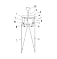
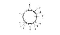
杭抜き用グラブ1の参考例を、図面を用いて説明する。図1及び図2に示すように、この杭抜き用グラブ1は、基部2と、一対のグラブ本体3と、グラブ駆動機構4と、を主要な構成要素としている。
A reference example of the pile pulling grab 1 will be described with reference to the drawings. As shown in FIGS. 1 and 2, the pile pulling grab 1 includes a
基部2は、この杭抜き用グラブ1の各構成部品を取り付ける際の取り付けベースとなる部材である。基部2の上部側には、引き抜きワイヤ5(図5(e)参照)、又は、基部2(杭抜き用グラブ1)を軸周りに回転させるオーガ(図示せず)が接続可能となっている。
The
グラブ本体3は、それぞれ半円筒面状をなし正面視逆三角形の一対の部材であり、その上端側がヒンジ6を介して基部2に接続され下端側が揺動可能となっている。一対のグラブ本体3は下方に向かうほど先細となっている。この一対のグラブ本体3の下端側を閉じることによって、地盤G中の既設杭Pを掴むことができる。また、一対のグラブ本体3の下端を完全に閉じることによって、その下端内側に土砂を掬う受け部が形成される。なお、既設杭Pを確実に掴むために、グラブ本体3の内面側に滑り止めのための突起などを形成してもよい。
Each of the grab
グラブ駆動機構4は、油圧シリンダ7と、リンク機構8と、油圧管9と、油圧装置10と、を備え、既設杭Pを掴む際に、一対のグラブ本体3のそれぞれのグラブ本体3と既設杭Pとの当接状態に対応して異なる揺動角度を与えることが可能となっている。なお、図2においては、油圧管9及び油圧装置10の記載を省略している。
The
油圧シリンダ7は、一対のグラブ本体3のそれぞれの位置に対応するように基部2に固定されている。この油圧シリンダ7は、作動油の油圧によって出没するロッド11を有している。リンク機構8は、油圧シリンダ7のロッド11と、この油圧シリンダ7に対応するグラブ本体3との間を連結している。油圧管9は、その下端側が二股に分岐しており、分岐した端部が各油圧シリンダ7に分かれて接続されている。油圧装置10は、油圧管9の上端側に接続されており、この油圧管9を介して各油圧シリンダ7に等圧の作動油を供給する。
The
図3に示すように、既設杭Pが一対のグラブ本体3のちょうど中間に位置している状態(すなわち、ケーシング12(図5(e)参照)と同軸の状態)で油圧装置10から油圧管9を介して各油圧シリンダ7に作動油を供給すると、この油圧シリンダ7からロッド11が突出し、このロッド11によってリンク機構8が下向きに押される。すると、リンク機構8に作用した下向きの力によって、このリンク機構8に接続された各グラブ本体3が、ヒンジ6の軸周りに揺動する。このとき、各油圧シリンダ7には、共通の油圧装置10から等圧の作動油が作用しているため、各グラブ本体3の揺動角度は等しくなり、一対のグラブ本体3によって、既設杭Pをその左右から確実に掴むことができる。
As shown in FIG. 3, the hydraulic pipe from the
その一方で、図4に示すように、既設杭Pが一対のグラブ本体3から偏心した状態(すなわち、ケーシング12から偏心した状態)で油圧装置10から油圧管9を介して各油圧シリンダ7に作動油を供給すると、この油圧シリンダ7からロッド11が突出し、このロッド11によってリンク機構8が下向きに押される。既設杭Pが偏心していると、まず、既設杭Pに近い側(図4に示す例では左側)のグラブ本体3(以下、一方側のグラブ本体3aと称する。)が既設杭Pに当接する。このとき、既設杭Pから遠い側(図4に示す例では右側)のグラブ本体3(以下、他方側のグラブ本体3bと称する。)は、まだ既設杭Pに当接していない(図4中に一点鎖線で示すグラブ本体3bを参照)。
On the other hand, as shown in FIG. 4, the existing pile P is eccentric from the pair of grab main bodies 3 (that is, eccentric from the casing 12) from the
ここで、油圧装置10からさらに作動油が供給されると、一方側のグラブ本体3aが既設杭Pとの当接状態を保ったまま、他方側のグラブ本体3bがさらに揺動して、他方側のグラブ本体3bも既設杭Pと当接する。このとき、両グラブ本体3a、3bは、異なる揺動角度となっている。図4は既設杭Pが偏心状態のときについて示したが、傾斜状態のときもこれと同様に、一対のグラブ本体3によって既設杭Pを確実に掴むことができる。
Here, when the hydraulic oil is further supplied from the
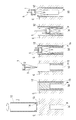
杭抜き方法の工程の参考例を図5(a)〜(f)に示す。この杭抜き方法は、掘削工程と、挿入工程と、引き抜き工程と、を主要な構成要素としている。なお、本図においては、油圧管9及び油圧装置10の記載を省略している。
Reference examples of the steps of the pile pulling method are shown in FIGS. 5A to 5F. This pile pulling method has an excavation step, an insertion step, and a pulling step as main components. In this figure, the description of the
掘削工程においては、下端に先端刃13が、内周に内周刃14がそれぞれ設けられた円筒状のケーシング12が用いられる(図5(a)参照)。オーガ(図示せず)を用いてこのケーシング12を軸周りに回転させて、先端刃13によって地盤Gを掘削することによって、このケーシング12を地盤G中に埋め込む。ケーシング12の埋め込み深さは、少なくともケーシング12の下端が既設杭Pの上端よりも下方となる深さとする必要があり、好ましくは既設杭Pがその全長に亘ってケーシング12で囲まれる深さとする。
In the excavation process, a
この掘削工程において、ケーシング12の内面側には、内周刃14によって土砂が排除された空洞部15が形成される(図5(b)参照)。また、ケーシング12の埋め込み後は、既設杭Pの上側に土砂が乗った状態となっている。この土砂は、上記において説明した杭抜き用グラブ1を用いて除去される(図5(c)参照)。
In this excavation process, a
挿入工程においては、上記において説明した杭抜き用グラブ1が用いられる。この杭抜き用グラブ1は、その上端側が巻き取り装置(図示せず)によって巻き取られる引き抜きワイヤ5によって吊り下げられた状態となっている(図5(e)参照)。この杭抜き用グラブ1の一対のグラブ本体3の下端を開いた状態とし、その下端を地盤G中の既設杭Pの上端よりも深い所定深さまで、ケーシング12の内面側に形成された空洞部15に挿入する(図5(d)参照)。
In the insertion step, the pile pulling grab 1 described above is used. The upper end side of the pile pulling grab 1 is suspended by a pulling
引き抜き工程においては、一対のグラブ本体3の下端を閉じて地盤G中の既設杭Pを掴んだ上で(図5(e)参照)、引き抜きワイヤ5によって杭抜き用グラブ1を上向きに引き上げることによって、既設杭Pが地盤Gから引き抜かれる(図5(f)参照)。一対のグラブ本体3で既設杭Pを掴むタイミングは適宜決めることができるが、既設杭Pの上端が杭抜き用グラブ1の基部2の下面に当接したタイミングとすることにより、この一対のグラブ本体3で既設杭Pを確実に掴むことができる。既設杭Pの引き抜き後に、ケーシング12の引き抜き、及び、穴の埋め戻しの各作業が行われる。
In the pulling step, after closing the lower ends of the pair of grab
本参考例に係る杭抜き方法によると、ケーシング12によって予め形成された空洞部15に一対のグラブ本体3を挿入すればよいため、その挿入作業が非常に簡便であり、作業コストの削減を図ることができる。
According to the pile pulling method according to this reference example , since it is sufficient to insert the pair of grab
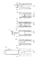
この発明に係る杭抜き方法の工程の一例を図6(a)〜(f)に示す。この杭抜き方法は、第一掘削工程と、第二掘削工程と、引き抜き工程と、を主要な構成要素としている。なお、本図においては、油圧管9及び油圧装置10の記載を省略している。
An example of the process of the pile pulling method according to the present invention is shown in FIGS. 6 (a) to 6 (f). This pile pulling method has a first excavation process, a second excavation process, and a drawing process as main components. In this figure, the description of the
第一掘削工程においては、下端に先端刃13が設けられた円筒状のケーシング12が用いられる(図6(a)参照)。オーガ(図示せず)を用いてこのケーシング12を軸周りに回転させて、先端刃13によって地盤Gを掘削することによって、このケーシング12を地盤G中に埋め込む(図6(b)参照)。ケーシング12の埋め込み深さは、少なくともケーシング12の下端が既設杭Pの上端よりも下方となる深さとする必要があり、好ましくは既設杭Pがその全長に亘ってケーシング12で囲まれる深さとする。また、ケーシング12の埋め込み後には、既設杭Pの上側に土砂が乗った状態となっている。この土砂は、上記において説明した杭抜き用グラブ1を用いて除去される(図6(c)参照)。
In the first excavation step, a
第二掘削工程においては、上記において説明した杭抜き用グラブ1が用いられる。この杭抜き用グラブ1の一対のグラブ本体3の下端には、地盤Gを掘削する掘削刃16(硬質チップ)が設けられている。なお、掘削刃16を設ける代わりに、クラブ本体3の下端に熱処理などの硬質化処理を施してもよい。この杭抜き用グラブ1の上端は、オーガ(図示せず)に接続されている。
In the second excavation step, the pile pulling grab 1 described above is used. An excavation blade 16 (hard tip) for excavating the ground G is provided at the lower end of the pair of grab
一対のグラブ本体3の下端を開いた状態でオーガによって杭抜き用グラブ1を軸周りに回転させて、この一対のグラブ本体3で地盤Gを掘り進む。このように、グラブ本体3を回転させることにより、既設杭Pとグラブ本体3が同軸状態となりやすく、この後に続く引き抜き工程において、一対のグラブ本体3で既設杭Pを掴みやすくすることができる。グラブ本体3によって掘り進む深さは、少なくともグラブ本体3の下端が地盤G中の既設杭Pの上端よりも下側となる深さとする必要があり、好ましくは既設杭Pの上端が杭抜き用グラブ1の基部2の下面に当接する深さとする(図6(d)参照)。
With the lower ends of the pair of
引き抜き工程においては、一対のグラブ本体3の下端を閉じて地盤G中の既設杭Pを掴んだ上で(図6(e)参照)、オーガごと杭抜き用グラブ1を上向きに引き上げることによって、既設杭Pが地盤Gから引き抜かれる(図6(f)参照)。一対のグラブ本体3で既設杭Pを掴むタイミングは適宜決めることができるが、既設杭Pの上端が杭抜き用グラブ1の基部2の下面に当接したタイミングとすることにより、この一対のグラブ本体3で既設杭Pを確実に掴むことができる。既設杭Pの引き抜き後に、ケーシング12の引き抜き、及び、穴の埋め戻しの各作業が行われる。
In the pulling process, the lower ends of the pair of
本例に係る杭抜き方法によると、一対のグラブ本体3の回転によって地盤Gを掘り進んだ後に、ツールの交換を行うことなく既設杭Pの引き抜き工程に移ることができるため、一連の杭抜き作業をスムーズに進めることができる。
According to the pile pulling method according to this example , after digging the ground G by rotating the pair of grab
なお、図5(a)〜(f)及び図6(a)〜(f)に示す杭抜き方法は、既設杭Pがケーシング12に対し同軸のときを例示して説明したが、既設杭Pがケーシング12に対し偏心又は傾斜しているときも同様の工程で杭抜き作業を行うことができる。
The pile pulling method shown in FIGS. 5 (a) to 5 (f) and FIGS. 6 (a) to 6 (f) has been described by exemplifying the case where the existing pile P is coaxial with the
上記において説明した杭抜き用グラブ1、及び、杭抜き方法はあくまでも例示であって、地盤G中の既設杭Pを確実に除去する、というこの発明の課題を解決し得る限りにおいて、杭抜き用グラブ1の構成や杭抜き方法の工程の一部を適宜変更することができる。 The pile-pulling grab 1 and the pile-pulling method described above are merely examples, and are for pile-pulling as long as the problem of the present invention of reliably removing the existing pile P in the ground G can be solved. Part of the structure of the grab 1 and the process of the pile pulling method can be changed as appropriate.
例えば、上記の実施形態においては、各グラブ本体3に対応して油圧シリンダ7を設け、各油圧シリンダ7に共通の油圧装置10から等圧の作動油を供給する構成としたが、各油圧シリンダ7に個別に油圧装置10を設け、各グラブ本体3の揺動を独立して制御する構成とすることができる可能性もある。
For example, in the above embodiment, the
1 杭抜き用グラブ
2 基部
3 グラブ本体
4 グラブ駆動機構
5 引き抜きワイヤ
6 ヒンジ
7 油圧シリンダ
8 リンク機構
9 油圧管
10 油圧装置
11 ロッド
12 ケーシング
13 先端刃
14 内周刃
15 空洞部
16 掘削刃
P 既設杭
G 地盤
1
7
Claims (1)
基部(2)と、前記基部(2)に上端側がヒンジ(6)を介して接続され下端側が揺動可能となっており、前記下端側を閉じることによって地盤(G)中の既設杭(P)を掴むことが可能な、それぞれ半円筒面状をなす一対のグラブ本体(3)と、前記既設杭(P)を掴む際に、前記一対のグラブ本体(3)のそれぞれのグラブ本体(3)に異なる揺動角度を与えることが可能なグラブ駆動機構(4)と、を有し、前記一対のグラブ本体(3)が下端に向かうほど先細となっており、前記一対のグラブ本体(3)の下端側をその半円筒面の端面同士が向かい合うように完全に閉じることによって、その下端内側に土砂を掬う受け部が形成され、前記グラブ駆動機構(4)が、前記一対のグラブ本体(3)のそれぞれに対応して設けられる油圧シリンダ(7)と、前記油圧シリンダ(7)とこれに対応する前記グラブ本体(3)をそれぞれ連結するリンク機構(8)と、前記各油圧シリンダ(7)にそれぞれ接続される油圧管(9)と、前記油圧管(9)を介して前記各油圧シリンダ(7)に作動油を供給する油圧装置(10)と、を有し、前記油圧管(9)は、その下端側が二股に分岐しており、分岐した端部が前記各油圧シリンダ(7)に分かれて接続され、前記油圧管(9)の上端側に前記油圧装置(10)が接続されており、前記油圧管(9)を介して前記各油圧シリンダ(7)に等圧の作動油を供給する杭抜き用グラブ(1)の前記一対のグラブ本体(3)の半円筒面の端面同士が向かい合うように完全に閉じて、その下端内側に形成される受け部によって前記既設杭(P)の上側に乗った土砂を掬って除去する除去工程と、
前記一対のグラブ本体(3)の下端を開いた状態で軸周りに回転させて、前記一対のグラブ本体(3)によって地盤(G)中の既設杭(P)の上端よりも深い所定の深さまで地盤(G)を掘削する第二掘削工程と、
前記一対のグラブ本体(3)の下端を閉じて地盤(G)中の既設杭(P)を掴み、前記既設杭(P)を地盤(G)から引き抜く引き抜き工程と、
を有する杭抜き方法。 A cylindrical casing (12) provided with a tip blade (13) at the lower end is rotated around an axis, the ground (G) is excavated by the tip blade (13), and the casing (12) is ground (G). ) The first excavation process to be embedded in
The upper end side is connected to the base portion (2) and the base portion (2) via a hinge (6) so that the lower end side can swing. By closing the lower end side, an existing pile (P) in the ground (G) ), A pair of grab bodies (3) each having a semi-cylindrical surface shape, and each grab body (3) of the pair of grab bodies (3) when gripping the existing pile (P). ) Has a grab drive mechanism (4) capable of giving different swing angles, and the pair of grab bodies (3) taper toward the lower end, and the pair of grab bodies (3) are tapered toward the lower end. By completely closing the lower end side of the semi-cylindrical surface so that the end faces of the semi-cylindrical surface face each other, a receiving portion for scooping earth and sand is formed inside the lower end surface, and the grab drive mechanism (4) forms the pair of grab bodies ( A hydraulic cylinder (7) provided corresponding to each of the 3), a link mechanism (8) for connecting the hydraulic cylinder (7) and the grab body (3) corresponding thereto, and each hydraulic cylinder (3). It has a hydraulic pipe (9) connected to each of the 7) and a hydraulic device (10) for supplying hydraulic oil to each hydraulic cylinder (7) via the hydraulic pipe (9). In (9), the lower end side thereof is bifurcated, the branched end portion is divided into the respective hydraulic cylinders (7) and connected, and the hydraulic device (10) is connected to the upper end side of the hydraulic pipe (9). are connected, the semi-cylindrical surfaces of the pair of glove body (3) of the hydraulic tube (9) pile vent glove supplies hydraulic oil isobaric to the each hydraulic cylinder (7) via (1) A removal step in which the end faces of the cylinders are completely closed so as to face each other, and the earth and sand on the upper side of the existing pile (P) is scooped and removed by a receiving portion formed inside the lower end thereof.
A predetermined depth deeper than the upper end of the existing pile (P) in the ground (G) by the pair of grab bodies (3) by rotating the pair of grab bodies (3) around the axis with the lower ends open. The second excavation process to excavate the ground (G) and
A pull-out step of closing the lower ends of the pair of grab bodies (3), grasping the existing pile (P) in the ground (G), and pulling out the existing pile (P) from the ground (G).
Pile pulling method with.
Priority Applications (1)
| Application Number | Priority Date | Filing Date | Title |
|---|---|---|---|
| JP2020024227A JP6834041B1 (en) | 2020-02-17 | 2020-02-17 | Pile pulling method |
Applications Claiming Priority (1)
| Application Number | Priority Date | Filing Date | Title |
|---|---|---|---|
| JP2020024227A JP6834041B1 (en) | 2020-02-17 | 2020-02-17 | Pile pulling method |
Publications (2)
| Publication Number | Publication Date |
|---|---|
| JP6834041B1 true JP6834041B1 (en) | 2021-02-24 |
| JP2021127654A JP2021127654A (en) | 2021-09-02 |
Family
ID=74661691
Family Applications (1)
| Application Number | Title | Priority Date | Filing Date |
|---|---|---|---|
| JP2020024227A Active JP6834041B1 (en) | 2020-02-17 | 2020-02-17 | Pile pulling method |
Country Status (1)
| Country | Link |
|---|---|
| JP (1) | JP6834041B1 (en) |
Cited By (1)
| Publication number | Priority date | Publication date | Assignee | Title |
|---|---|---|---|---|
| CN113931186A (en) * | 2021-10-18 | 2022-01-14 | 中交第二航务工程局有限公司 | Auxiliary pile foundation pulling-out construction method under space-limited condition |
Family Cites Families (9)
| Publication number | Priority date | Publication date | Assignee | Title |
|---|---|---|---|---|
| JPH06158660A (en) * | 1992-11-18 | 1994-06-07 | Takachiho Kogyo Kk | Appliance for extracting pile for shovel machine |
| JP3803186B2 (en) * | 1997-10-24 | 2006-08-02 | 丸順重工株式会社 | Hydraulic circuit configuration of multiple actuators and excavation attachment equipped with the hydraulic circuit |
| JP2006207252A (en) * | 2005-01-28 | 2006-08-10 | Hitachi Sumitomo Heavy Industries Construction Crane Co Ltd | Pile pull-out machine |
| JP4638898B2 (en) * | 2007-07-04 | 2011-02-23 | 三和機工株式会社 | Hammer grab |
| JP5535894B2 (en) * | 2010-12-22 | 2014-07-02 | 植田基工株式会社 | Method of removing underground obstacles and lifting device for removing underground obstacles used therefor |
| JP6498484B2 (en) * | 2015-03-20 | 2019-04-10 | 大裕株式会社 | Underground obstacle removal device |
| CN105332376B (en) * | 2015-11-27 | 2017-06-20 | 太原科技大学 | Hydraulic mechanical hand-lifting stake clamping device and pile-drawing machine |
| JP6758629B2 (en) * | 2016-12-15 | 2020-09-23 | 株式会社シロタ | Existing pile gripping device |
| JP7119381B2 (en) * | 2018-01-19 | 2022-08-17 | 日本基礎技術株式会社 | UNDERGROUND STRUCTURE REMOVAL DEVICE AND UNDERGROUND STRUCTURE REMOVAL METHOD USING THE SAME |
-
2020
- 2020-02-17 JP JP2020024227A patent/JP6834041B1/en active Active
Cited By (2)
| Publication number | Priority date | Publication date | Assignee | Title |
|---|---|---|---|---|
| CN113931186A (en) * | 2021-10-18 | 2022-01-14 | 中交第二航务工程局有限公司 | Auxiliary pile foundation pulling-out construction method under space-limited condition |
| CN113931186B (en) * | 2021-10-18 | 2023-08-15 | 中交第二航务工程局有限公司 | Auxiliary pile foundation pulling construction method under space-limited condition |
Also Published As
| Publication number | Publication date |
|---|---|
| JP2021127654A (en) | 2021-09-02 |
Similar Documents
| Publication | Publication Date | Title |
|---|---|---|
| JP6774132B1 (en) | Construction method of steel pipe pile | |
| JP2006241919A (en) | Pile construction machine and pile construction method | |
| JP4734235B2 (en) | Anchor bolt construction method, anchor bolt buried hole drilling method, and drilling device | |
| JP6834041B1 (en) | Pile pulling method | |
| JP2009263966A (en) | Removal method of existing pile | |
| JP4478348B2 (en) | Steel pipe pile driving method and apparatus | |
| JP3004903B2 (en) | Drilling rig | |
| JP3683229B2 (en) | Existing pile removal method and equipment | |
| JP3165997B2 (en) | Casting method and equipment for sheet piles | |
| JP5033405B2 (en) | Excavation apparatus and excavation method | |
| JP7104571B2 (en) | Underground obstacle removal device | |
| JP2004084164A (en) | Removal method for existing pile and its device | |
| JP6286097B1 (en) | U-type steel sheet pile press-fitting device | |
| JP2001323767A (en) | Pit excavator | |
| CN112324441A (en) | Construction method for removing underground shield segments by full-slewing drilling machine | |
| JP3343501B2 (en) | Excavation method | |
| JP7414317B2 (en) | Earth and sand backfill equipment and earth and sand backfill method | |
| JPH0941859A (en) | Hard rock layer drilling method and its device | |
| JP3004267B1 (en) | Drilling rig | |
| JPS5819836B2 (en) | Large-diameter vertical hole drilling method | |
| JP2005314871A (en) | Removing device for underground obstacle and removing method for underground obstacle | |
| JP3422742B2 (en) | Drilling rig | |
| JPH10227191A (en) | Inner excavator for excavating device | |
| JPH0765451B2 (en) | Buried material construction method under the surface structure | |
| JP2004176504A (en) | Excavator |
Legal Events
| Date | Code | Title | Description |
|---|---|---|---|
| A621 | Written request for application examination |
Free format text: JAPANESE INTERMEDIATE CODE: A621 Effective date: 20200217 |
|
| A871 | Explanation of circumstances concerning accelerated examination |
Free format text: JAPANESE INTERMEDIATE CODE: A871 Effective date: 20200217 |
|
| A975 | Report on accelerated examination |
Free format text: JAPANESE INTERMEDIATE CODE: A971005 Effective date: 20200225 |
|
| A131 | Notification of reasons for refusal |
Free format text: JAPANESE INTERMEDIATE CODE: A131 Effective date: 20200414 |
|
| A521 | Request for written amendment filed |
Free format text: JAPANESE INTERMEDIATE CODE: A523 Effective date: 20200609 |
|
| A131 | Notification of reasons for refusal |
Free format text: JAPANESE INTERMEDIATE CODE: A131 Effective date: 20200929 |
|
| A521 | Request for written amendment filed |
Free format text: JAPANESE INTERMEDIATE CODE: A523 Effective date: 20201117 |
|
| TRDD | Decision of grant or rejection written | ||
| A01 | Written decision to grant a patent or to grant a registration (utility model) |
Free format text: JAPANESE INTERMEDIATE CODE: A01 Effective date: 20210105 |
|
| A61 | First payment of annual fees (during grant procedure) |
Free format text: JAPANESE INTERMEDIATE CODE: A61 Effective date: 20210203 |
|
| R150 | Certificate of patent or registration of utility model |
Ref document number: 6834041 Country of ref document: JP Free format text: JAPANESE INTERMEDIATE CODE: R150 |
|
| R250 | Receipt of annual fees |
Free format text: JAPANESE INTERMEDIATE CODE: R250 |