JP6833771B2 - Power storage module - Google Patents
Power storage module Download PDFInfo
- Publication number
- JP6833771B2 JP6833771B2 JP2018155519A JP2018155519A JP6833771B2 JP 6833771 B2 JP6833771 B2 JP 6833771B2 JP 2018155519 A JP2018155519 A JP 2018155519A JP 2018155519 A JP2018155519 A JP 2018155519A JP 6833771 B2 JP6833771 B2 JP 6833771B2
- Authority
- JP
- Japan
- Prior art keywords
- electrode
- power storage
- negative electrode
- storage module
- resin portion
- Prior art date
- Legal status (The legal status is an assumption and is not a legal conclusion. Google has not performed a legal analysis and makes no representation as to the accuracy of the status listed.)
- Active
Links
- 238000003860 storage Methods 0.000 title claims description 118
- 229920005989 resin Polymers 0.000 claims description 138
- 239000011347 resin Substances 0.000 claims description 138
- 238000007789 sealing Methods 0.000 claims description 113
- 229910052751 metal Inorganic materials 0.000 claims description 102
- 239000002184 metal Substances 0.000 claims description 102
- 239000008151 electrolyte solution Substances 0.000 claims description 49
- 230000002093 peripheral effect Effects 0.000 claims description 11
- 239000012670 alkaline solution Substances 0.000 claims description 7
- 239000000565 sealant Substances 0.000 claims description 6
- 230000000694 effects Effects 0.000 description 21
- 239000000463 material Substances 0.000 description 20
- XLYOFNOQVPJJNP-UHFFFAOYSA-N water Substances O XLYOFNOQVPJJNP-UHFFFAOYSA-N 0.000 description 18
- 239000005871 repellent Substances 0.000 description 17
- 239000007788 liquid Substances 0.000 description 14
- 230000002940 repellent Effects 0.000 description 13
- 239000003566 sealing material Substances 0.000 description 10
- 230000033001 locomotion Effects 0.000 description 9
- 239000004743 Polypropylene Substances 0.000 description 8
- -1 nickel hydrogen Chemical class 0.000 description 8
- 229920001155 polypropylene Polymers 0.000 description 8
- PXHVJJICTQNCMI-UHFFFAOYSA-N nickel Substances [Ni] PXHVJJICTQNCMI-UHFFFAOYSA-N 0.000 description 6
- 230000001133 acceleration Effects 0.000 description 5
- 230000015572 biosynthetic process Effects 0.000 description 5
- 238000000465 moulding Methods 0.000 description 5
- 239000010426 asphalt Substances 0.000 description 4
- 238000003780 insertion Methods 0.000 description 4
- 230000037431 insertion Effects 0.000 description 4
- 239000007773 negative electrode material Substances 0.000 description 4
- 229910052759 nickel Inorganic materials 0.000 description 4
- 239000004745 nonwoven fabric Substances 0.000 description 4
- 239000007774 positive electrode material Substances 0.000 description 4
- YXFVVABEGXRONW-UHFFFAOYSA-N Toluene Chemical compound CC1=CC=CC=C1 YXFVVABEGXRONW-UHFFFAOYSA-N 0.000 description 3
- 229910052739 hydrogen Inorganic materials 0.000 description 3
- 239000001257 hydrogen Substances 0.000 description 3
- 238000001746 injection moulding Methods 0.000 description 3
- 230000009545 invasion Effects 0.000 description 3
- 238000010030 laminating Methods 0.000 description 3
- 230000000452 restraining effect Effects 0.000 description 3
- 239000004698 Polyethylene Substances 0.000 description 2
- 239000004734 Polyphenylene sulfide Substances 0.000 description 2
- 239000003795 chemical substances by application Substances 0.000 description 2
- 239000011248 coating agent Substances 0.000 description 2
- 238000000576 coating method Methods 0.000 description 2
- 230000000052 comparative effect Effects 0.000 description 2
- 239000011888 foil Substances 0.000 description 2
- 230000017525 heat dissipation Effects 0.000 description 2
- 238000002347 injection Methods 0.000 description 2
- 239000007924 injection Substances 0.000 description 2
- 238000004519 manufacturing process Methods 0.000 description 2
- 238000000034 method Methods 0.000 description 2
- 229920000573 polyethylene Polymers 0.000 description 2
- 229920005672 polyolefin resin Polymers 0.000 description 2
- 229920000069 polyphenylene sulfide Polymers 0.000 description 2
- 239000003507 refrigerant Substances 0.000 description 2
- 238000007788 roughening Methods 0.000 description 2
- 238000003466 welding Methods 0.000 description 2
- BQCIDUSAKPWEOX-UHFFFAOYSA-N 1,1-Difluoroethene Chemical compound FC(F)=C BQCIDUSAKPWEOX-UHFFFAOYSA-N 0.000 description 1
- YCKRFDGAMUMZLT-UHFFFAOYSA-N Fluorine atom Chemical compound [F] YCKRFDGAMUMZLT-UHFFFAOYSA-N 0.000 description 1
- UFHFLCQGNIYNRP-UHFFFAOYSA-N Hydrogen Chemical compound [H][H] UFHFLCQGNIYNRP-UHFFFAOYSA-N 0.000 description 1
- HBBGRARXTFLTSG-UHFFFAOYSA-N Lithium ion Chemical compound [Li+] HBBGRARXTFLTSG-UHFFFAOYSA-N 0.000 description 1
- KWYUFKZDYYNOTN-UHFFFAOYSA-M Potassium hydroxide Chemical compound [OH-].[K+] KWYUFKZDYYNOTN-UHFFFAOYSA-M 0.000 description 1
- 229910000831 Steel Inorganic materials 0.000 description 1
- 238000010521 absorption reaction Methods 0.000 description 1
- 239000011149 active material Substances 0.000 description 1
- 239000000853 adhesive Substances 0.000 description 1
- 230000001070 adhesive effect Effects 0.000 description 1
- 239000003513 alkali Substances 0.000 description 1
- 239000000956 alloy Substances 0.000 description 1
- 229910045601 alloy Inorganic materials 0.000 description 1
- 239000003990 capacitor Substances 0.000 description 1
- 150000001875 compounds Chemical class 0.000 description 1
- 238000005260 corrosion Methods 0.000 description 1
- 230000007797 corrosion Effects 0.000 description 1
- 230000007423 decrease Effects 0.000 description 1
- 238000007599 discharging Methods 0.000 description 1
- 238000010292 electrical insulation Methods 0.000 description 1
- 238000009713 electroplating Methods 0.000 description 1
- 239000008393 encapsulating agent Substances 0.000 description 1
- 238000004146 energy storage Methods 0.000 description 1
- 239000012530 fluid Substances 0.000 description 1
- 229910052731 fluorine Inorganic materials 0.000 description 1
- 239000011737 fluorine Substances 0.000 description 1
- 229920001973 fluoroelastomer Polymers 0.000 description 1
- 125000000524 functional group Chemical group 0.000 description 1
- 238000003475 lamination Methods 0.000 description 1
- 229910001416 lithium ion Inorganic materials 0.000 description 1
- 229920000609 methyl cellulose Polymers 0.000 description 1
- 125000002496 methyl group Chemical group [H]C([H])([H])* 0.000 description 1
- 239000001923 methylcellulose Substances 0.000 description 1
- 235000010981 methylcellulose Nutrition 0.000 description 1
- BFDHFSHZJLFAMC-UHFFFAOYSA-L nickel(ii) hydroxide Chemical compound [OH-].[OH-].[Ni+2] BFDHFSHZJLFAMC-UHFFFAOYSA-L 0.000 description 1
- 238000009832 plasma treatment Methods 0.000 description 1
- 229920001083 polybutene Polymers 0.000 description 1
- 229920000642 polymer Polymers 0.000 description 1
- 229920000098 polyolefin Polymers 0.000 description 1
- 229920001955 polyphenylene ether Polymers 0.000 description 1
- 239000010959 steel Substances 0.000 description 1
- 239000002759 woven fabric Substances 0.000 description 1
Images


Classifications
-
- H—ELECTRICITY
- H01—ELECTRIC ELEMENTS
- H01M—PROCESSES OR MEANS, e.g. BATTERIES, FOR THE DIRECT CONVERSION OF CHEMICAL ENERGY INTO ELECTRICAL ENERGY
- H01M10/00—Secondary cells; Manufacture thereof
- H01M10/34—Gastight accumulators
- H01M10/345—Gastight metal hydride accumulators
-
- H—ELECTRICITY
- H01—ELECTRIC ELEMENTS
- H01M—PROCESSES OR MEANS, e.g. BATTERIES, FOR THE DIRECT CONVERSION OF CHEMICAL ENERGY INTO ELECTRICAL ENERGY
- H01M50/00—Constructional details or processes of manufacture of the non-active parts of electrochemical cells other than fuel cells, e.g. hybrid cells
- H01M50/10—Primary casings, jackets or wrappings of a single cell or a single battery
- H01M50/183—Sealing members
-
- H—ELECTRICITY
- H01—ELECTRIC ELEMENTS
- H01G—CAPACITORS; CAPACITORS, RECTIFIERS, DETECTORS, SWITCHING DEVICES OR LIGHT-SENSITIVE DEVICES, OF THE ELECTROLYTIC TYPE
- H01G11/00—Hybrid capacitors, i.e. capacitors having different positive and negative electrodes; Electric double-layer [EDL] capacitors; Processes for the manufacture thereof or of parts thereof
- H01G11/10—Multiple hybrid or EDL capacitors, e.g. arrays or modules
- H01G11/12—Stacked hybrid or EDL capacitors
-
- H—ELECTRICITY
- H01—ELECTRIC ELEMENTS
- H01G—CAPACITORS; CAPACITORS, RECTIFIERS, DETECTORS, SWITCHING DEVICES OR LIGHT-SENSITIVE DEVICES, OF THE ELECTROLYTIC TYPE
- H01G11/00—Hybrid capacitors, i.e. capacitors having different positive and negative electrodes; Electric double-layer [EDL] capacitors; Processes for the manufacture thereof or of parts thereof
- H01G11/78—Cases; Housings; Encapsulations; Mountings
- H01G11/80—Gaskets; Sealings
-
- H—ELECTRICITY
- H01—ELECTRIC ELEMENTS
- H01M—PROCESSES OR MEANS, e.g. BATTERIES, FOR THE DIRECT CONVERSION OF CHEMICAL ENERGY INTO ELECTRICAL ENERGY
- H01M10/00—Secondary cells; Manufacture thereof
- H01M10/24—Alkaline accumulators
- H01M10/26—Selection of materials as electrolytes
-
- H—ELECTRICITY
- H01—ELECTRIC ELEMENTS
- H01M—PROCESSES OR MEANS, e.g. BATTERIES, FOR THE DIRECT CONVERSION OF CHEMICAL ENERGY INTO ELECTRICAL ENERGY
- H01M10/00—Secondary cells; Manufacture thereof
- H01M10/24—Alkaline accumulators
- H01M10/28—Construction or manufacture
- H01M10/281—Large cells or batteries with stacks of plate-like electrodes
- H01M10/282—Large cells or batteries with stacks of plate-like electrodes with bipolar electrodes
-
- H—ELECTRICITY
- H01—ELECTRIC ELEMENTS
- H01M—PROCESSES OR MEANS, e.g. BATTERIES, FOR THE DIRECT CONVERSION OF CHEMICAL ENERGY INTO ELECTRICAL ENERGY
- H01M10/00—Secondary cells; Manufacture thereof
- H01M10/42—Methods or arrangements for servicing or maintenance of secondary cells or secondary half-cells
- H01M10/4235—Safety or regulating additives or arrangements in electrodes, separators or electrolyte
-
- H—ELECTRICITY
- H01—ELECTRIC ELEMENTS
- H01M—PROCESSES OR MEANS, e.g. BATTERIES, FOR THE DIRECT CONVERSION OF CHEMICAL ENERGY INTO ELECTRICAL ENERGY
- H01M4/00—Electrodes
- H01M4/02—Electrodes composed of, or comprising, active material
- H01M4/13—Electrodes for accumulators with non-aqueous electrolyte, e.g. for lithium-accumulators; Processes of manufacture thereof
- H01M4/134—Electrodes based on metals, Si or alloys
-
- H—ELECTRICITY
- H01—ELECTRIC ELEMENTS
- H01M—PROCESSES OR MEANS, e.g. BATTERIES, FOR THE DIRECT CONVERSION OF CHEMICAL ENERGY INTO ELECTRICAL ENERGY
- H01M4/00—Electrodes
- H01M4/02—Electrodes composed of, or comprising, active material
- H01M4/36—Selection of substances as active materials, active masses, active liquids
- H01M4/38—Selection of substances as active materials, active masses, active liquids of elements or alloys
-
- H—ELECTRICITY
- H01—ELECTRIC ELEMENTS
- H01M—PROCESSES OR MEANS, e.g. BATTERIES, FOR THE DIRECT CONVERSION OF CHEMICAL ENERGY INTO ELECTRICAL ENERGY
- H01M50/00—Constructional details or processes of manufacture of the non-active parts of electrochemical cells other than fuel cells, e.g. hybrid cells
- H01M50/10—Primary casings, jackets or wrappings of a single cell or a single battery
- H01M50/183—Sealing members
- H01M50/184—Sealing members characterised by their shape or structure
-
- H—ELECTRICITY
- H01—ELECTRIC ELEMENTS
- H01M—PROCESSES OR MEANS, e.g. BATTERIES, FOR THE DIRECT CONVERSION OF CHEMICAL ENERGY INTO ELECTRICAL ENERGY
- H01M50/00—Constructional details or processes of manufacture of the non-active parts of electrochemical cells other than fuel cells, e.g. hybrid cells
- H01M50/10—Primary casings, jackets or wrappings of a single cell or a single battery
- H01M50/183—Sealing members
- H01M50/19—Sealing members characterised by the material
- H01M50/197—Sealing members characterised by the material having a layered structure
-
- H—ELECTRICITY
- H01—ELECTRIC ELEMENTS
- H01M—PROCESSES OR MEANS, e.g. BATTERIES, FOR THE DIRECT CONVERSION OF CHEMICAL ENERGY INTO ELECTRICAL ENERGY
- H01M50/00—Constructional details or processes of manufacture of the non-active parts of electrochemical cells other than fuel cells, e.g. hybrid cells
- H01M50/50—Current conducting connections for cells or batteries
- H01M50/543—Terminals
- H01M50/545—Terminals formed by the casing of the cells
-
- H—ELECTRICITY
- H01—ELECTRIC ELEMENTS
- H01M—PROCESSES OR MEANS, e.g. BATTERIES, FOR THE DIRECT CONVERSION OF CHEMICAL ENERGY INTO ELECTRICAL ENERGY
- H01M50/00—Constructional details or processes of manufacture of the non-active parts of electrochemical cells other than fuel cells, e.g. hybrid cells
- H01M50/70—Arrangements for stirring or circulating the electrolyte
- H01M50/77—Arrangements for stirring or circulating the electrolyte with external circulating path
-
- H—ELECTRICITY
- H01—ELECTRIC ELEMENTS
- H01M—PROCESSES OR MEANS, e.g. BATTERIES, FOR THE DIRECT CONVERSION OF CHEMICAL ENERGY INTO ELECTRICAL ENERGY
- H01M4/00—Electrodes
- H01M4/02—Electrodes composed of, or comprising, active material
- H01M2004/026—Electrodes composed of, or comprising, active material characterised by the polarity
- H01M2004/029—Bipolar electrodes
-
- H—ELECTRICITY
- H01—ELECTRIC ELEMENTS
- H01M—PROCESSES OR MEANS, e.g. BATTERIES, FOR THE DIRECT CONVERSION OF CHEMICAL ENERGY INTO ELECTRICAL ENERGY
- H01M50/00—Constructional details or processes of manufacture of the non-active parts of electrochemical cells other than fuel cells, e.g. hybrid cells
- H01M50/60—Arrangements or processes for filling or topping-up with liquids; Arrangements or processes for draining liquids from casings
- H01M50/668—Means for preventing spilling of liquid or electrolyte, e.g. when the battery is tilted or turned over
-
- Y—GENERAL TAGGING OF NEW TECHNOLOGICAL DEVELOPMENTS; GENERAL TAGGING OF CROSS-SECTIONAL TECHNOLOGIES SPANNING OVER SEVERAL SECTIONS OF THE IPC; TECHNICAL SUBJECTS COVERED BY FORMER USPC CROSS-REFERENCE ART COLLECTIONS [XRACs] AND DIGESTS
- Y02—TECHNOLOGIES OR APPLICATIONS FOR MITIGATION OR ADAPTATION AGAINST CLIMATE CHANGE
- Y02E—REDUCTION OF GREENHOUSE GAS [GHG] EMISSIONS, RELATED TO ENERGY GENERATION, TRANSMISSION OR DISTRIBUTION
- Y02E60/00—Enabling technologies; Technologies with a potential or indirect contribution to GHG emissions mitigation
- Y02E60/10—Energy storage using batteries
-
- Y—GENERAL TAGGING OF NEW TECHNOLOGICAL DEVELOPMENTS; GENERAL TAGGING OF CROSS-SECTIONAL TECHNOLOGIES SPANNING OVER SEVERAL SECTIONS OF THE IPC; TECHNICAL SUBJECTS COVERED BY FORMER USPC CROSS-REFERENCE ART COLLECTIONS [XRACs] AND DIGESTS
- Y02—TECHNOLOGIES OR APPLICATIONS FOR MITIGATION OR ADAPTATION AGAINST CLIMATE CHANGE
- Y02P—CLIMATE CHANGE MITIGATION TECHNOLOGIES IN THE PRODUCTION OR PROCESSING OF GOODS
- Y02P70/00—Climate change mitigation technologies in the production process for final industrial or consumer products
- Y02P70/50—Manufacturing or production processes characterised by the final manufactured product
Description
本発明は、蓄電モジュールに関する。 The present invention relates to a power storage module.
従来の蓄電モジュールとして、電極板の一方面に正極が形成され、他方面に負極が形成されたバイポーラ電極を備えるバイポーラ電池が知られている(特許文献1参照)。バイポーラ電池は、セパレータを介して複数のバイポーラ電極を積層してなる積層体を備えている。積層体の側面には、積層方向に隣り合うバイポーラ電極間を封止する封止体が設けられており、バイポーラ電極間に形成された内部空間に電解液が収容されている。 As a conventional power storage module, a bipolar battery including a bipolar electrode having a positive electrode formed on one surface of an electrode plate and a negative electrode formed on the other surface is known (see Patent Document 1). The bipolar battery includes a laminate formed by laminating a plurality of bipolar electrodes via a separator. On the side surface of the laminated body, a sealing body for sealing between the bipolar electrodes adjacent to each other in the stacking direction is provided, and the electrolytic solution is housed in the internal space formed between the bipolar electrodes.
上述したような蓄電モジュールでは、積層体における積層方向の一端に、内面に負極が形成された電極板からなる負極終端電極が配置されている。この負極終端電極の電極板の縁部についても封止体によって封止されているが、電解液がアルカリ溶液からなる場合、いわゆるアルカリクリープ現象により、電解液が負極終端電極の電極板の表面を伝わり、封止体と当該電極板との間を通って当該電極板の外面側に滲み出ることがある。電解液が外面側に漏れ出て拡散すると、例えば負極終端電極に隣接して配置された導電板の腐食や、負極終端電極と拘束部材との短絡などが生じるおそれがあり、信頼性の観点から好ましくない。 In the power storage module as described above, a negative electrode terminal electrode made of an electrode plate having a negative electrode formed on the inner surface is arranged at one end of the laminated body in the stacking direction. The edge of the electrode plate of the negative electrode terminal electrode is also sealed by a sealant, but when the electrolytic solution is composed of an alkaline solution, the electrolytic solution causes the electrolytic solution to cover the surface of the electrode plate of the negative electrode terminal electrode due to the so-called alkaline creep phenomenon. It may be transmitted, pass between the sealing body and the electrode plate, and exude to the outer surface side of the electrode plate. If the electrolytic solution leaks to the outer surface side and diffuses, for example, corrosion of the conductive plate arranged adjacent to the negative electrode terminal electrode or short circuit between the negative electrode terminal electrode and the restraint member may occur, and from the viewpoint of reliability. Not preferred.
そこで、本発明は、信頼性の向上が図られた蓄電モジュールを提供することを目的とする。 Therefore, an object of the present invention is to provide a power storage module with improved reliability.
本発明に係る蓄電モジュールは、第1方向に沿って積層された複数の電極を含む積層体と、電極の縁部に接合された第1封止部を含み、隣り合う電極の間の内部空間を形成すると共に内部空間を封止する封止体と、内部空間に収容されたアルカリ溶液を含む電解液と、を備えた蓄電モジュールであって、電極は、複数のバイポーラ電極と負極終端電極とを含み、バイポーラ電極は、第1面及び第1面の反対側の第2面を含む電極板と、第1面に設けられた正極と、第2面に設けられた負極と、を含み、負極終端電極は、第3面及び前記第3面の反対側の第4面を含む電極板と第4面に設けられた負極とを含み、第4面がバイポーラ電極の電極板の第1面を向くように、第1方向の積層体の一端に配置されており、電解液が内部空間から負極終端電極を伝って蓄電モジュールの外部に至る経路上に、内部空間とは別の余剰空間を有し、積層体は、負極終端電極の電極板に対して第1方向の外側に配置された金属板を有し、余剰空間は、第1封止部と負極終端電極の電極板と金属板とによって形成され、蓄電モジュールの外部に対して気密性を有している。 The power storage module according to the present invention includes a laminated body including a plurality of electrodes laminated along the first direction and a first sealing portion bonded to the edge of the electrodes, and is an internal space between adjacent electrodes. a power storage module comprising a sealing member that abolish seal the internal space to form a, a, and an electrolytic solution containing an alkaline solution contained in the internal space, the electrodes, the plurality of bipolar electrodes and the negative end electrodes The bipolar electrode includes an electrode plate including a first surface and a second surface opposite to the first surface, a positive electrode provided on the first surface, and a negative electrode provided on the second surface. , negative end electrode includes a negative electrode provided in the electrode plate and the fourth surface including a third surface and a fourth surface opposite to the third surface, the fourth surface of the bipolar electrode of the electrode plate 1 It is arranged at one end of the laminated body in the first direction so as to face the surface, and is a surplus space different from the internal space on the path from the internal space to the outside of the power storage module through the negative electrode terminal electrode. The laminate has a metal plate arranged outside in the first direction with respect to the electrode plate of the negative electrode terminal electrode, and the surplus space is the first sealing portion, the electrode plate of the negative electrode terminal electrode, and metal. It is formed by a plate and has airtightness to the outside of the power storage module .
この蓄電モジュールにおいては、電解液が内部空間から負極終端電極を伝って蓄電モジュールの外部に至る経路上に、内部空間とは別の余剰空間を有する。これにより、電解液が滲み出す起点となる負極終端電極の電極板と第1封止部との間の隙間に、外部の空気中に含まれる水分が入り込むことを抑制できる。したがって、アルカリクリープ現象の加速条件となる外部の湿度の影響が抑制されるので、電解液が蓄電モジュールの外部に滲み出ることを抑制することができる。 In this power storage module, the electrolytic solution has a surplus space different from the internal space on the path from the internal space to the outside of the power storage module through the negative electrode terminal electrode. As a result, it is possible to prevent moisture contained in the outside air from entering the gap between the electrode plate of the negative electrode terminal electrode, which is the starting point for the electrolytic solution to seep out, and the first sealing portion. Therefore, since the influence of external humidity, which is an acceleration condition of the alkaline creep phenomenon, is suppressed, it is possible to suppress the electrolytic solution from seeping out to the outside of the power storage module.
本発明に係る蓄電モジュールにおいては、積層体は、負極終端電極の電極板に対して第1方向の外側に配置された金属板を有し、第1封止部と負極終端電極の電極板と金属板とによって余剰空間が形成されていてもよい。この構成においても、第1封止部と負極終端電極と金属板とによる余剰空間が電解液の移動経路上に形成されている。したがって、電解液が蓄電モジュールの外部に滲み出ることを抑制することができる。 In the power storage module according to the present invention, the laminate has a metal plate arranged outside in the first direction with respect to the electrode plate of the negative electrode terminal electrode, and has a first sealing portion and an electrode plate of the negative electrode terminal electrode. An extra space may be formed by the metal plate. Also in this configuration, an excess space formed by the first sealing portion, the negative electrode terminal electrode, and the metal plate is formed on the moving path of the electrolytic solution. Therefore, it is possible to prevent the electrolytic solution from seeping out of the power storage module.
本発明に係る蓄電モジュールは、第1方向に沿って積層された複数の電極を含む積層体と、第1方向における積層体の一端に設けられた金属板と、電極に接合され、隣り合う電極の間に内部空間を形成すると共に内部空間を封止する第1封止部を含む封止体と、内部空間に収容されたアルカリ溶液を含む電解液と、を備え、電極は、複数のバイポーラ電極と負極終端電極とを含み、封止体は、負極終端電極と金属板との間に配置された第1樹脂部を含み、第1方向における第1樹脂部の一方の面は、負極終端電極に結合され、第1方向における第1樹脂部の他方の面は、金属板に結合されている。 The power storage module according to the present invention has a laminate including a plurality of electrodes laminated along the first direction, a metal plate provided at one end of the laminate in the first direction, and electrodes bonded to the electrodes and adjacent to each other. The electrode includes a sealant including a first sealing portion that forms an internal space between the two electrodes and seals the internal space, and an electrolytic solution containing an alkaline solution contained in the internal space. The sealing body includes a first resin portion arranged between the negative electrode termination electrode and the metal plate, and one surface of the first resin portion in the first direction is the negative electrode termination. It is coupled to the electrode and the other surface of the first resin portion in the first direction is coupled to the metal plate.
この蓄電モジュールにおいては、封止体は、負極終端電極と金属板との間に配置された第1樹脂部を含み、第1方向における第1樹脂部の一方の面は、負極終端電極に結合され、第1方向における第1樹脂部の他方の面は、金属板に結合されている。これにより、第1樹脂部と負極終端電極と金属板とによって、電解液が収容されていない余剰空間が形成されている。この余剰空間は、アルカリクリープ現象による電解液の移動経路上に位置している。これにより、電解液が滲み出す起点となる負極終端電極の電極板と第1封止部との間の隙間に、外部の空気中に含まれる水分が入り込むことを抑制できる。したがって、アルカリクリープ現象の加速条件となる外部の湿度の影響が抑制されるので、電解液が蓄電モジュールの外部に滲み出ることを抑制することができる。 In this power storage module, the encapsulant includes a first resin portion arranged between the negative electrode terminal electrode and the metal plate, and one surface of the first resin portion in the first direction is coupled to the negative electrode terminal electrode. The other surface of the first resin portion in the first direction is bonded to the metal plate. As a result, an excess space in which the electrolytic solution is not accommodated is formed by the first resin portion, the negative electrode terminal electrode, and the metal plate. This surplus space is located on the movement path of the electrolytic solution due to the alkaline creep phenomenon. As a result, it is possible to prevent moisture contained in the outside air from entering the gap between the electrode plate of the negative electrode terminal electrode, which is the starting point for the electrolytic solution to seep out, and the first sealing portion. Therefore, since the influence of external humidity, which is an acceleration condition of the alkaline creep phenomenon, is suppressed, it is possible to suppress the electrolytic solution from seeping out to the outside of the power storage module.
本発明に係る蓄電モジュールにおいては、バイポーラ電極は、第1面及び第1面の反対側の第2面を含む電極板と、第1面に設けられた正極と、第2面に設けられた負極と、を含み、負極終端電極は、電極板と第2面に設けられた負極とを含み、第2面が積層体の内側になるように、第1方向の積層体の一端においてバイポーラ電極と金属板との間に配置されており、金属板は、負極終端電極の第1面に対向する第3面と第3面と反対の第4面とを含み、第3面の周縁部において第1樹脂部に溶着されていてもよい。この構成においても、第1樹脂部と負極終端電極と金属板とによる余剰空間が電解液の移動経路上に形成されている。したがって、電解液が蓄電モジュールの外部に滲み出ることを抑制することができる。 In the power storage module according to the present invention, the bipolar electrodes are provided on the electrode plate including the first surface and the second surface opposite to the first surface, the positive electrode provided on the first surface, and the second surface. The negative electrode terminal electrode includes the negative electrode and the negative electrode terminal electrode includes the electrode plate and the negative electrode provided on the second surface, and the bipolar electrode is provided at one end of the laminated body in the first direction so that the second surface is inside the laminated body. It is arranged between the metal plate and the metal plate, and the metal plate includes a third surface facing the first surface of the negative electrode terminal electrode and a fourth surface opposite to the third surface, and at the peripheral edge of the third surface. It may be welded to the first resin portion. Also in this configuration, an excess space formed by the first resin portion, the negative electrode terminal electrode, and the metal plate is formed on the movement path of the electrolytic solution. Therefore, it is possible to prevent the electrolytic solution from seeping out of the power storage module.
本発明に係る蓄電モジュールにおいては、第1封止部は、負極終端電極の第1面に溶着された第1樹脂部を含み、金属板は、負極終端電極の第1面に対向する第3面と第3面と反対の第4面とを含み、第3面の周縁部において第1樹脂部に溶着されていてもよい。この構成においても、第1封止部と負極終端電極と金属板とによる余剰空間が電解液の移動経路上に形成されている。したがって、電解液が蓄電モジュールの外部に滲み出ることを抑制することができる。 In the power storage module according to the present invention, the first sealing portion includes the first resin portion welded to the first surface of the negative electrode terminal electrode, and the metal plate is the third facing the first surface of the negative electrode terminal electrode. It may include a surface and a fourth surface opposite to the third surface, and may be welded to the first resin portion at the peripheral edge portion of the third surface. Also in this configuration, an excess space formed by the first sealing portion, the negative electrode terminal electrode, and the metal plate is formed on the moving path of the electrolytic solution. Therefore, it is possible to prevent the electrolytic solution from seeping out of the power storage module.
本発明に係る蓄電モジュールにおいては、複数の第1封止部及び第2樹脂部を外側から包囲するように第1封止部及び第2樹脂部に接合された第2封止部をさらに備え、第2封止部は、第1方向からみて金属板及び第2樹脂部に重複する重複部を含むと共に、重複部において第2樹脂部に溶着されていてもよい。この場合、第2封止部によって内部空間が確実に封止される。また、第2封止部の重複部によって第2樹脂部の変形が抑制される結果、第2樹脂部と第4面との間に隙間が生じることが抑制される。これにより、アルカリクリープによる漏液がより確実に抑制される。 The power storage module according to the present invention further includes a second sealing portion joined to the first sealing portion and the second resin portion so as to surround the plurality of first sealing portions and the second resin portion from the outside. The second sealing portion may include an overlapping portion that overlaps the metal plate and the second resin portion when viewed from the first direction, and may be welded to the second resin portion at the overlapping portion. In this case, the internal space is surely sealed by the second sealing portion. Further, as a result of suppressing the deformation of the second resin portion by the overlapping portion of the second sealing portion, it is suppressed that a gap is generated between the second resin portion and the fourth surface. As a result, leakage due to alkaline creep is more reliably suppressed.
本発明に係る蓄電モジュールにおいては、金属板は、第1樹脂部に溶着された枠状の被溶着部と、被溶着部の内側において被溶着部よりも負極終端電極の第1面側に位置して第1面に接触された被接触部と、を含んでいてもよい。この場合、金属板と負極終端電極との間に形成される余剰空間が制限される。これにより、当該余剰空間の湿度の影響が抑制される。 In the power storage module according to the present invention, the metal plate is located at the frame-shaped welded portion welded to the first resin portion and inside the welded portion on the first surface side of the negative electrode terminal electrode with respect to the welded portion. It may include a contacted portion that has been brought into contact with the first surface. In this case, the excess space formed between the metal plate and the negative electrode terminal electrode is limited. As a result, the influence of humidity in the surplus space is suppressed.
本発明に係る蓄電モジュールにおいては、第1面、第3面及び第4面の封止体に溶着される領域は、粗面化されていてもよい。この構成によれば、アンカー効果によって封止体と、第1面、第3面及び第4面との結合強度の向上を図ることができる。 In the power storage module according to the present invention, the regions welded to the sealed bodies on the first, third, and fourth surfaces may be roughened. According to this configuration, the bonding strength between the sealing body and the first, third, and fourth surfaces can be improved by the anchor effect.
本発明に係る蓄電モジュールにおいては、金属板は、電極板であってもよい。この場合、電極板と別途に金属板を用意する必要がない。これにより、低コストにて上記の構成を実現可能である。 In the power storage module according to the present invention, the metal plate may be an electrode plate. In this case, it is not necessary to prepare a metal plate separately from the electrode plate. As a result, the above configuration can be realized at low cost.
本発明に係る蓄電モジュールは、第1方向に沿って積層された複数の電極を含む積層体と、第1方向における積層体の一端に設けられた金属板と、電極の縁部に溶着され、隣り合う電極の間に内部空間を形成すると共に内部空間を封止するための第1封止部と、内部空間に収容されたアルカリ溶液を含む電解液と、を備え、電極は、複数のバイポーラ電極と負極終端電極とを含み、バイポーラ電極は、第1面及び第1面の反対側の第2面を含む電極板と、第1面に設けられた正極と、第2面に設けられた負極と、を含み、負極終端電極は、電極板と第2面に設けられた負極とを含み、第2面が積層体の内側になるように、第1方向の積層体の一端においてバイポーラ電極と金属板との間に配置されており、第1封止部は、負極終端電極の第1面に溶着された第1樹脂部を含み、金属板は、負極終端電極の第1面に対向する第3面と第3面と反対の第4面とを含み、第3面の周縁部において第1樹脂部に溶着されており、第1面及び第3面の第1樹脂部に溶着される領域は、粗面化されている。 The power storage module according to the present invention is welded to a laminate including a plurality of electrodes laminated along the first direction, a metal plate provided at one end of the laminate in the first direction, and an edge of the electrodes. A first sealing portion for forming an internal space between adjacent electrodes and sealing the internal space, and an electrolytic solution containing an alkaline solution contained in the internal space are provided, and the electrodes are a plurality of bipolar electrodes. The bipolar electrode includes an electrode and a negative electrode terminal electrode, and the bipolar electrode is provided on an electrode plate including a first surface and a second surface opposite to the first surface, a positive electrode provided on the first surface, and a second surface. The negative electrode terminal electrode includes the negative electrode and the negative electrode terminal electrode includes the electrode plate and the negative electrode provided on the second surface, and the bipolar electrode is provided at one end of the laminated body in the first direction so that the second surface is inside the laminated body. The first sealing portion is arranged between the metal plate and the metal plate, and the first sealing portion includes a first resin portion welded to the first surface of the negative electrode terminal electrode, and the metal plate faces the first surface of the negative electrode terminal electrode. It includes the third surface and the fourth surface opposite to the third surface, and is welded to the first resin portion at the peripheral edge of the third surface, and is welded to the first resin portion of the first and third surfaces. The area is roughened.
この蓄電モジュールにおいては、積層体の電極の間には、第1封止部によって電解液を収容する内部空間が形成されている。また、積層体の一端には、複数の電極のうち、電極板の第2面が積層体の内側になるように負極終端電極が配置されている。負極終端電極における積層体の外側に臨む第1面には、第1封止部としての第1樹脂部が溶着されている。一方、積層体の一端には、金属板が設けられている。これにより、負極終端電極は、電極のうちのバイポーラ電極とこの金属板と間に配置されることになる。すなわち、負極終端電極のさらに外側に金属板が設けられることになる。そして、金属板は、負極終端電極の第1面に対向する第3面の周縁部において、負極終端電極の第1面に溶着された第1樹脂部に溶着されている。 In this power storage module, an internal space for accommodating the electrolytic solution is formed between the electrodes of the laminated body by the first sealing portion. Further, at one end of the laminated body, a negative electrode terminal electrode is arranged so that the second surface of the electrode plate is inside the laminated body among the plurality of electrodes. A first resin portion as a first sealing portion is welded to the first surface of the negative electrode terminal electrode facing the outside of the laminate. On the other hand, a metal plate is provided at one end of the laminated body. As a result, the negative electrode terminal electrode is arranged between the bipolar electrode of the electrodes and the metal plate. That is, a metal plate is provided on the outer side of the negative electrode terminal electrode. The metal plate is welded to the first resin portion welded to the first surface of the negative electrode terminal electrode at the peripheral edge portion of the third surface facing the first surface of the negative electrode terminal electrode.
このような構成とすることにより、次のような効果が得られる。すなわち、第1の効果として、第1樹脂部と比較して剛性の高い金属板が負極終端電極の第1面上の第1樹脂部に溶着されることにより、第1樹脂部と負極終端電極の第1面とが引きはがされるように第1樹脂部が変形することが抑制される。また、第2の効果として、負極終端電極の外側にさらに金属板が設けられることにより、電極間の内部空間への外部からの水分の侵入が抑制される。さらに、第3の効果として、負極終端電極から外部に通じる経路上において、負極終端電極の第1面と第1樹脂部との溶着箇所、及び、金属板の第3面と第1樹脂部の溶着箇所の少なくとも2段階のシールが形成される。 With such a configuration, the following effects can be obtained. That is, as the first effect, the metal plate having higher rigidity than the first resin portion is welded to the first resin portion on the first surface of the negative electrode terminal electrode, whereby the first resin portion and the negative electrode terminal electrode are welded. It is suppressed that the first resin portion is deformed so as to be peeled off from the first surface of the above. Further, as a second effect, by further providing a metal plate on the outside of the negative electrode termination electrode, the invasion of moisture from the outside into the internal space between the electrodes is suppressed. Further, as a third effect, on the path leading from the negative electrode terminal electrode to the outside, the welded portion between the first surface and the first resin portion of the negative electrode terminal electrode, and the third surface and the first resin portion of the metal plate. At least two stages of sealing of the welded part are formed.
第1の効果によって、第1樹脂部と負極終端電極の第1面との間において、アルカリクリープによる電解液の漏液の経路となり得る隙間が生じることが抑制される。また、第2の効果によって、アルカリクリープの加速条件となる外部の湿度の影響が抑制される。さらに、第3の効果によって、多段階のシールにより漏液速度が低減される。この蓄電モジュールによれば、これらの効果が複合的に得られる結果、アルカリクリープによる漏液が確実に抑制され、信頼性が向上される。 The first effect suppresses the formation of a gap between the first resin portion and the first surface of the negative electrode terminal electrode, which can serve as a path for leakage of the electrolytic solution due to alkaline creep. In addition, the second effect suppresses the influence of external humidity, which is an acceleration condition for alkaline creep. In addition, due to the third effect, the leakage rate is reduced by the multi-step sealing. According to this power storage module, as a result of obtaining these effects in combination, leakage due to alkaline creep is surely suppressed, and reliability is improved.
本発明に係る蓄電モジュールにおいては、第4面の周縁部から第1樹脂部にわたって延在して配置され、第4面及び第1樹脂部に溶着された第2樹脂部をさらに備え、第4面の第2樹脂部が溶着される領域は、粗面化されていてもよい。この場合、負極終端電極から外部に通じる経路上において、金属板の第4面と第2樹脂部の溶着箇所としてシールがさらに形成される。この結果、さらに多段階(3段階)のシールにより漏液速度が確実に低減され、アルカリクリープによる漏液がより確実に抑制される。 In the power storage module according to the present invention, a second resin portion extending from the peripheral edge portion of the fourth surface to the first resin portion and welded to the fourth surface and the first resin portion is further provided, and the fourth The region where the second resin portion of the surface is welded may be roughened. In this case, a seal is further formed as a welding point between the fourth surface and the second resin portion of the metal plate on the path leading from the negative electrode terminal electrode to the outside. As a result, the liquid leakage rate is surely reduced by the multi-step (three-step) sealing, and the liquid leakage due to alkaline creep is more surely suppressed.
本発明に係る蓄電モジュールにおいては、複数の第1封止部及び第2樹脂部を外側から包囲するように第1封止部及び第2樹脂部に接合された第2封止部をさらに備え、第2封止部は、第1方向からみて金属板及び第2樹脂部に重複する重複部を含むと共に、重複部において第2樹脂部に溶着されていてもよい。この場合、第2封止部によって内部空間が確実に封止される。また、第2封止部の重複部によって第2樹脂部の変形が抑制される結果、第2樹脂部と第4面との間に隙間が生じることが抑制される。これにより、アルカリクリープによる漏液がより確実に抑制される。 The power storage module according to the present invention further includes a second sealing portion joined to the first sealing portion and the second resin portion so as to surround the plurality of first sealing portions and the second resin portion from the outside. The second sealing portion may include an overlapping portion that overlaps the metal plate and the second resin portion when viewed from the first direction, and may be welded to the second resin portion at the overlapping portion. In this case, the internal space is surely sealed by the second sealing portion. Further, as a result of suppressing the deformation of the second resin portion by the overlapping portion of the second sealing portion, it is suppressed that a gap is generated between the second resin portion and the fourth surface. As a result, leakage due to alkaline creep is more reliably suppressed.
本発明に係る蓄電モジュールにおいては、金属板は、第1樹脂部に溶着された環状の被溶着部と、被溶着部の内側において被溶着部よりも負極終端電極の第1面側に位置して第1面に接触された被接触部と、を含んでもよい。この場合、金属板と負極終端電極との間に形成される余剰空間が制限される。これにより、当該余剰空間の湿度の影響が抑制される。 In the power storage module according to the present invention, the metal plate is located at the annular welded portion welded to the first resin portion and inside the welded portion on the first surface side of the negative electrode terminal electrode with respect to the welded portion. It may include a contacted portion that is in contact with the first surface. In this case, the excess space formed between the metal plate and the negative electrode terminal electrode is limited. As a result, the influence of humidity in the surplus space is suppressed.
本発明に係る蓄電モジュールにおいては、金属板は、電極板であってもよい。この場合、電極板と別途に金属板を用意する必要がない。これにより、低コストにて上記の構成を実現可能である。 In the power storage module according to the present invention, the metal plate may be an electrode plate. In this case, it is not necessary to prepare a metal plate separately from the electrode plate. As a result, the above configuration can be realized at low cost.
本発明によれば、信頼性の向上が図られた蓄電モジュールを提供することができる。 According to the present invention, it is possible to provide a power storage module with improved reliability.
以下、図面を参照して蓄電モジュールの一実施形態について説明する。なお、図面の説明においては、同一の要素同士、或いは、相当する要素同士には、互いに同一の符号を付し、重複する説明を省略する場合がある。 Hereinafter, an embodiment of the power storage module will be described with reference to the drawings. In the description of the drawings, the same elements or the corresponding elements may be designated by the same reference numerals, and duplicate description may be omitted.
図1は、蓄電装置の一実施形態を示す概略断面図である。図1に示される蓄電装置1は、例えば、フォークリフト、ハイブリッド自動車、電気自動車等の各種車両のバッテリとして用いられる。蓄電装置1は、積層された複数の蓄電モジュール4を含むモジュール積層体2と、モジュール積層体2に対してその積層方向に拘束荷重を付加する拘束部材3とを備えている。
FIG. 1 is a schematic cross-sectional view showing an embodiment of a power storage device. The power storage device 1 shown in FIG. 1 is used as a battery for various vehicles such as forklifts, hybrid vehicles, and electric vehicles. The power storage device 1 includes a
モジュール積層体2は、複数(ここでは3つ)の蓄電モジュール4と、複数(ここでは4つ)の導電板5と、を含む。蓄電モジュール4は、バイポーラ電池であり、積層方向から見て矩形状をなしている。蓄電モジュール4は、例えばニッケル水素二次電池、リチウムイオン二次電池等の二次電池、又は電気二重層キャパシタである。以下の説明では、ニッケル水素二次電池を例示する。
The
積層方向に互いに隣り合う蓄電モジュール4同士は、導電板5を介して電気的に接続されている。導電板5は、積層方向に互いに隣り合う蓄電モジュール4間と、積層端に位置する蓄電モジュール4の外側と、にそれぞれ配置されている。積層端に位置する蓄電モジュール4の外側に配置された一方の導電板5には、正極端子6が接続されている。積層端に位置する蓄電モジュール4の外側に配置された他方の導電板5には、負極端子7が接続されている。正極端子6及び負極端子7は、例えば導電板5の縁部から積層方向に交差する方向に引き出されている。正極端子6及び負極端子7により、蓄電装置1の充放電が実施される。
The
導電板5の内部には、空気等の冷媒を流通させる複数の流路5aが設けられている。流路5aは、例えば、積層方向と、正極端子6及び負極端子7の引き出し方向と、にそれぞれ交差(直交)する方向に沿って延在している。導電板5は、蓄電モジュール4同士を電気的に接続する接続部材としての機能のほか、これらの流路5aに冷媒を流通させることにより、蓄電モジュール4で発生した熱を放熱する放熱板としての機能を併せ持つ。なお、図1の例では、積層方向から見た導電板5の面積は、蓄電モジュール4の面積よりも小さいが、放熱性の向上の観点から、導電板5の面積は、蓄電モジュール4の面積と同じであってもよく、蓄電モジュール4の面積よりも大きくてもよい。
Inside the
拘束部材3は、モジュール積層体2を積層方向に挟む一対のエンドプレート8と、エンドプレート8同士を締結する締結ボルト9及びナット10と、によって構成されている。エンドプレート8は、積層方向から見た蓄電モジュール4及び導電板5の面積よりも一回り大きい面積を有する矩形の金属板である。エンドプレート8の内側面(モジュール積層体2側の面)には、電気絶縁性を有するフィルムFが設けられている。フィルムFにより、エンドプレート8と導電板5との間が絶縁されている。
The restraint member 3 is composed of a pair of end plates 8 that sandwich the
エンドプレート8の縁部には、モジュール積層体2よりも外側となる位置に挿通孔8aが設けられている。締結ボルト9は、一方のエンドプレート8の挿通孔8aから他方のエンドプレート8の挿通孔8aに向かって通され、他方のエンドプレート8の挿通孔8aから突出した締結ボルト9の先端部分には、ナット10が螺合されている。これにより、蓄電モジュール4及び導電板5がエンドプレート8によって挟持されてモジュール積層体2としてユニット化されると共に、モジュール積層体2に対して積層方向に拘束荷重が付加される。
An
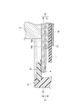
次に、蓄電モジュール4の構成について詳細に説明する。図2は、図1に示された蓄電モジュールの内部構成を示す概略断面図である。図3は、図2の部分拡大図である。図2,3に示されるように、蓄電モジュール4は、電極積層体(積層体)11と、電極積層体11を封止する樹脂製の封止体12と、を備えている。電極積層体11は、セパレータ13を介して、積層方向D(第1方向)に沿って積層された複数の電極(複数のバイポーラ電極14、単一の負極終端電極(電極)18、及び、単一の正極終端電極19)を含む。ここでは、電極積層体11の積層方向Dはモジュール積層体2の積層方向と一致している。電極積層体11は、積層方向Dに延びる側面11aを有している。
Next, the configuration of the
バイポーラ電極14は、第1面15a及び第1面15aの反対側の第2面15bを含む電極板15、第1面15aに設けられた正極16、第2面15bに設けられた負極17を含んでいる。正極16は、正極活物質が電極板15に塗工されることにより形成される正極活物質層である。負極17は、負極活物質が電極板15に塗工されることにより形成される負極活物質層である。電極積層体11において、一のバイポーラ電極14の正極16は、セパレータ13を挟んで積層方向Dに隣り合う別のバイポーラ電極14の負極17と対向している。電極積層体11において、一のバイポーラ電極14の負極17は、セパレータ13を挟んで積層方向Dに隣り合うさらに別のバイポーラ電極14の正極16と対向している。
The
負極終端電極18は、電極板15、及び電極板15の第2面15bに設けられた負極17を含んでいる。負極終端電極18は、その第2面15bが電極積層体11の内側(積層方向Dについての中心側)になるように、積層方向Dの一端に配置されている。負極終端電極18の負極17は、セパレータ13を介して、積層方向Dの一端のバイポーラ電極14の正極16と対向している。正極終端電極19は、電極板15、及び電極板15の第1面15aに設けられた正極16を含んでいる。正極終端電極19は、その第1面15aが電極積層体11の内側になるように、積層方向Dの他端に配置されている。正極終端電極19の正極16は、セパレータ13を介して、積層方向Dの他端のバイポーラ電極14の負極17と対向している。
The negative
負極終端電極18の電極板15の第1面15aは、電極積層体11の外側に臨む面である。負極終端電極18の第1面15aには、後述する金属板50を介して、導電板5が電気的に接続されている。また、正極終端電極19の電極板15の第2面15bには、蓄電モジュール4に隣接する別の導電板5が接触している。拘束部材3からの拘束荷重は、導電板5を介して負極終端電極18及び正極終端電極19から電極積層体11に付加される。すなわち、導電板5は、積層方向Dに沿って電極積層体11に拘束荷重を付加する拘束部材でもある。
The
電極板15は、例えば、ニッケル又はニッケルメッキ鋼板といった金属からなる。一例として、電極板15は、ニッケルからなる矩形の金属箔である。電極板15の縁部(バイポーラ電極14、負極終端電極18、及び、正極終端電極19の縁部)15cは、矩形枠状をなし、正極活物質及び負極活物質が塗工されない未塗工領域となっている。正極16を構成する正極活物質としては、例えば水酸化ニッケルが挙げられる。負極17を構成する負極活物質としては、例えば水素吸蔵合金が挙げられる。本実施形態では、電極板15の第2面15bにおける負極17の形成領域は、電極板15の第1面15aにおける正極16の形成領域に対して一回り大きくなっている。
The
セパレータ13は、例えばシート状に形成されている。セパレータ13としては、ポリエチレン(PE)、ポリプロピレン(PP)等のポリオレフィン系樹脂からなる多孔質フィルム、ポリプロピレン、メチルセルロース等からなる織布又は不織布等が例示される。セパレータ13は、フッ化ビニリデン樹脂化合物で補強されたものであってもよい。なお、セパレータ13は、シート状に限られず、袋状のものを用いてもよい。
The
封止体12は、例えば絶縁性の樹脂によって、全体として矩形の筒状に形成されている。封止体12は、縁部15cを包囲するように電極積層体11の側面11aに設けられている。封止体12は、側面11aにおいて縁部15cを保持している。封止体12は、縁部15cに溶着された複数の第1封止部21と、側面11aに沿って第1封止部21を外側から包囲するように第1封止部21に接合された単一の第2封止部22と、を有している。
The sealing
第1封止部21は、積層方向Dから見て、矩形環状をなし、縁部15cの全周にわたって連続的に設けられている。第1封止部21は、電極板15の第1面15aに溶着されて気密に接合されている。第1封止部21は、例えば超音波又は熱によって溶着されている。第1封止部21は所定の厚さ(積層方向Dの長さ)を有するフィルムである。電極板15の端面は、第1封止部21から露出している。第1封止部21の内側の一部は、積層方向Dに互いに隣り合う電極板15の縁部15c同士の間に位置しており、外側の一部は、電極板15から外側に張り出している。第1封止部21は、当該外側の一部において第2封止部22に保持されている。積層方向Dに沿って互いに隣り合う第1封止部21同士は、互いに離間している。第1封止部21は、負極終端電極18の第1面15aに溶着された第1樹脂部21Aを含む。ここでは、第1封止部21のうちの1つが第1樹脂部21Aである。なお、第1封止部21は、正極終端電極19の電極板15の第2面15b側にも、溶着されていてもよい。
The
第2封止部22は、電極積層体11及び第1封止部21の外側に設けられ、蓄電モジュール4の外壁(筐体)を構成している。第2封止部22は、例えば樹脂の射出成型によって形成され、積層方向Dに沿って電極積層体11の全長にわたって延在している。第2封止部22は、積層方向Dを軸方向として延在する筒状(環状)を呈している。第2封止部22は、例えば、射出成型時の熱によって第1封止部21の外表面に溶着(接合)されている。
The
第2封止部22は、第1封止部21と共に、積層方向Dに沿って互いに隣り合うバイポーラ電極14の間、積層方向Dに沿って互いに隣り合う負極終端電極18とバイポーラ電極14との間、及び、積層方向Dに沿って互いに隣り合う正極終端電極19とバイポーラ電極14との間をそれぞれ封止している。これにより、バイポーラ電極14の間、負極終端電極18とバイポーラ電極14との間、及び、正極終端電極19とバイポーラ電極14との間には、それぞれ気密に仕切られた内部空間Vが形成されている。すなわち、第1封止部21及び第2封止部22は、隣り合う電極の間に内部空間Vを形成すると共に内部空間Vを封止するためのものである。この内部空間Vには、例えば水酸化カリウム水溶液等のアルカリ溶液を含む電解液(不図示)が収容されている。電解液は、セパレータ13、正極16及び負極17内に含浸されている。
The
ここで、蓄電モジュール4は、金属板50と第2樹脂部51とを備える。金属板50は、積層方向Dにおける電極積層体11の一端(負極終端電極18側の端部)に設けられている。金属板50は、負極終端電極18の第1面15aに対向する第3面50aと、第3面50aの反対側の第4面50bと、を含む。金属板50の第4面50bは、導電板5に接触している。金属板50は、積層方向Dに沿って電極と共に積層されている。これにより、負極終端電極18は、積層方向Dに沿って金属板50とバイポーラ電極14との間に配置されることになる。換言すれば、蓄電モジュール4においては、負極終端電極18のさらに外側に金属板50が設けられることになる。
Here, the
金属板50は、第1樹脂部21Aに溶着されると共に負極終端電極18の第1面15aに接触している。より具体的には、金属板50は、第1樹脂部21A及び第1面15a上に配置されて第1樹脂部21Aに溶着された矩形環状の被溶着部52と、被溶着部52の内側において被溶着部52よりも負極終端電極18の第1面15a側に位置して(窪んで)第1面15aに接触された矩形状の被接触部53と、を含む。被溶着部52と被接触部53とは互いに連続している。金属板50と負極終端電極18との間(第3面50aと第1面15aとの間)には、第1樹脂部21Aの厚さ(積層方向Dに沿った長さ)に相当する余剰空間VAが形成され得るが、金属板50が被接触部53において負極終端電極18側に窪んでいることから、この余剰空間VAが狭く制限されている。なお、金属板50は、任意の金属により構成することができるが、一例として電極板15と同一のものとすることができる。すなわち、一例として金属板50は電極板15である。この場合、金属板50は、活物質層が形成されていない金属箔(未塗工箔)である。
The
第2樹脂部51は、積層方向Dからみて第1樹脂部21Aと略同一の形状を呈している。すなわち、第2樹脂部51は、矩形環状であり、また、所定の厚さを有するフィルムである。第2樹脂部51は、金属板50の第4面50bの周縁部から第1樹脂部21Aにわたって延在して配置されている。第2樹脂部51は、第4面50b及び第1樹脂部21Aに溶着されている。第2封止部22は、複数の第1封止部21及びこの第2樹脂部51を外側から包囲するように第1封止部21及び第2樹脂部51に接合されている。第2封止部22は、積層方向Dからみて金属板50及び第2樹脂部51に重複する重複部22Aを含むと共に、重複部22Aにおいて第2樹脂部51に溶着されている。
The
第1封止部21(第1樹脂部21A)、第2封止部22、及び、第2樹脂部51は、例えば、絶縁性の樹脂であって、ポリプロピレン(PP)、ポリフェニレンサルファイド(PPS)、又は変性ポリフェニレンエーテル(変性PPE)等から構成され得る。
The first sealing portion 21 (
なお、第1面15a、第3面50a、及び、第4面50bには、第1樹脂部21A又は第2樹脂部51に溶着される領域が形成される。具体的には、積層方向Dからみたとき、第1面15aにおける第1樹脂部21Aに重複する領域A1、及び、第3面50aにおける第1樹脂部21Aに重複する領域A2は、第1樹脂部21Aに溶着される領域である。また、積層方向Dからみて、第4面50bにおける第2樹脂部51に重複する領域A3は、第2樹脂部51に溶着される領域である。領域A1〜A3は、矩形環状である。少なくともこれらの領域A1〜A3は、粗面化されている。ここでは、第1面15a、第3面50a、及び、第4面50bの全体が粗面化されている。
A region to be welded to the
第1面15a、第3面50a、及び、第4面50bは、例えば、電解メッキ処理で複数の突起が形成されることにより粗面化されている。これにより、第1面15a、第3面50a、及び、第4面50bにおける第1樹脂部21A又は第2樹脂部51との接合界面では、溶融状態の第1樹脂部21A又は第2樹脂部51が粗面化により形成された凹部内に入り込み、アンカー効果が発揮される。これにより、互いの結合力を向上させることができる。粗面化の際に形成される突起は、例えば、基端側から先端側に向かって先太りとなる形状を有している。これにより、互いに隣接する突起の間の断面形状がアンダーカット形状となり、アンカー効果が生じ易い。
The
ここで、蓄電モジュール4は、撥水材60をさらに有していてもよい。撥水材60は、第1面15a、第2面15b、第3面50a、及び、第4面50bにおいて溶着に供されていない領域に設けることができる。ここでは、撥水材60は、負極終端電極18の第2面15bの第1封止部21に対向する領域A4、第3面50aの第1樹脂部21Aに溶着される領域A2から第3面50aの内側に延びる領域A5、及び、第4面50bの第2樹脂部51が溶着される領域A3から第4面50bの内側に延びる領域A6に設けられている。ただし、撥水材60は、これらの領域A4〜A6のうちの少なくとも1つに設けられていればよい。領域A4は、負極終端電極18に隣接するバイポーラ電極14に溶着された第1封止部21に対向している。領域A5は、余剰空間VAに臨む領域である。領域A6は、蓄電モジュール4の外側に臨む領域である。
Here, the
撥水材60は、一例として膜状に形成されている。撥水材60は、フッ素系の樹脂材料(例えば、株式会社ハーベス製「OS−90HF」)、フッ素ゴム、フッ素系・メチル系の官能基を有したポリマー等を塗布することにより形成され得る。
The
また、蓄電モジュール4は、吸液部材31をさらに有していてもよい。吸液部材31は、金属板50の第4面50b上に設けられている。吸液部材31は、例えば不織布によってシート状に形成されている。この不織布を構成する材料としては、ポリオレフィンなどが例示される。不織布には、吸水性を向上するために、プラズマ処理が施されていてもよい。吸液部材31の厚さ(積層方向Dに沿っての長さ)は、例えば数百μm程度である。吸液部材31は、例えば積層方向Dから見て矩形環状をなしており、導電板5を包囲している。
Further, the
引き続いて、蓄電装置1の製造方法の一例について説明する。この方法では、まず、上記の蓄電モジュール4を製造する。蓄電モジュール4の製造方法は、一次成形工程と、積層工程と、二次成形工程と、注入工程と、を備える。一次成形工程では、所定数のバイポーラ電極14と負極終端電極18及び正極終端電極19を用意し、それぞれの電極板15の縁部15cの第1面15aに第1封止部21を溶着する。また、金属板50を用意し、その第4面50bに第2樹脂部51を溶着する。
Subsequently, an example of the manufacturing method of the power storage device 1 will be described. In this method, first, the above-mentioned
積層工程では、第1封止部21が電極板15の縁部15c同士の間に配置されるようにセパレータ13を介してバイポーラ電極14、負極終端電極18、及び正極終端電極19を積層することにより、電極積層体11を形成する。また、第1樹脂部21A上に第2樹脂部51が配置されるように、金属板50を電極積層体11の一端に配置する。二次成形工程では、射出成形の金型(不図示)内に電極積層体11及び金属板50を配置した後、金型内に溶融樹脂を射出することにより、第1封止部21及び第2樹脂部51を包囲するように第2封止部22を形成する。これにより、電極積層体11の側面11aに封止体12が形成される。注入工程では、二次成形工程の後、バイポーラ電極14,14間の内部空間Vに電解液を注入する。これにより、蓄電モジュール4が得られる。
In the laminating step, the
続いて、蓄電モジュール4の作用・効果について説明する。図4は、比較例に係る蓄電モジュールの一部拡大断面図である。図4に示される例では、金属板50が設けられていない。このため、例えば、内圧の上昇に伴って負極終端電極18の電極板15に荷重が付加されると、当該電極板15に溶着された第1樹脂部21Aが変形するおそれがある。この場合、第1樹脂部21Aと電極板15との間に隙間が生じ、当該隙間を介して電解液Lの漏液が生じるおそれがある。
Subsequently, the operation / effect of the
蓄電モジュールでは、いわゆるアルカリクリープ現象により、電解液Lが負極終端電極18の電極板15上を伝わり、第1樹脂部21Aと電極板15との間の隙間を通って電極板15の第1面15a側に滲み出ることがある。図4には、アルカリクリープ現象における電解液Lの移動経路が矢印Aで示されている。このアルカリクリープ現象は、電気化学的な要因と流体現象等により、蓄電装置の充電時及び放電時並びに無負荷時において生じ得る。アルカリクリープ現象は、負極電位、水分、及び電解液Lの通り道がそれぞれ存在することにより生じる。
In the power storage module, the electrolytic solution L is transmitted on the
これに対して、蓄電モジュール4においては、電極積層体11の電極の間には、第1封止部21によって電解液を収容する内部空間Vが形成されている。また、電極積層体11の一端には、複数の電極のうち、電極板15の第2面15bが電極積層体11の内側になるように負極終端電極18が配置されている。負極終端電極18における電極積層体11の外側に臨む第1面15aには、第1封止部21としての第1樹脂部21Aが溶着されている。一方、電極積層体11の一端には、金属板50が設けられている。これにより、負極終端電極18は、電極のうちのバイポーラ電極14とこの金属板50と間に配置されることになる。すなわち、負極終端電極18のさらに外側に金属板50が設けられることになる。そして、金属板50は、負極終端電極18の第1面15aに対向する第3面50aの周縁部において、負極終端電極18の第1面15aに溶着された第1樹脂部21Aに溶着されている。
On the other hand, in the
このような構成とすることにより、次のような効果が得られる。すなわち、第1の効果として、第1樹脂部21Aと比較して剛性の高い金属板50が負極終端電極18の第1面15a上の第1樹脂部21Aに溶着されることにより、第1樹脂部21aと負極終端電極18の第1面15aとが引きはがされるように第1樹脂部21Aが変形することが抑制される。また、第2の効果として、負極終端電極18の外側にさらに金属板50が設けられることにより、内部空間Vへの外部からの水分の侵入が抑制される。さらに、第3の効果として、負極終端電極18から外部に通じる経路上において、負極終端電極18の第1面15aと第1樹脂部21Aとの溶着箇所、及び、金属板50の第3面50aと第1樹脂部21Aの溶着箇所の少なくとも2段階のシールが形成される。
With such a configuration, the following effects can be obtained. That is, as the first effect, the
第1の効果によって、第1樹脂部21Aと負極終端電極18の第1面15aとの間において、アルカリクリープによる電解液の漏液の経路となり得る隙間が生じることが抑制される。また、第2の効果によって、アルカリクリープの加速条件となる外部の湿度の影響が抑制される。さらに、第3の効果によって、多段階のシールにより漏液速度が低減される。この蓄電モジュール4によれば、これらの効果が複合的に得られる結果、アルカリクリープによる漏液が確実に抑制され、信頼性が向上される。
The first effect suppresses the formation of a gap between the
また、蓄電モジュール4は、金属板50の第4面50bの周縁部から第1樹脂部21Aにわたって延在して配置され、第4面50b及び第1樹脂部21Aに溶着された第2樹脂部51をさらに備えている。そして、第4面50bの第2樹脂部51が溶着される領域A3は、粗面化されている。このため、負極終端電極18から外部に通じる経路上において、金属板50の第4面50bと第2樹脂部51の溶着箇所(領域A3)としてシールがさらに形成される。この結果、さらに多段階(3段階)のシールにより漏液速度が確実に低減され、アルカリクリープによる漏液がより確実に抑制される。
Further, the
また、蓄電モジュール4は、複数の第1封止部21及び第2樹脂部51を外側から包囲するように第1封止部21及び第2樹脂部51に接合された第2封止部22をさらに備える。第2封止部22は、積層方向Dからみて金属板50及び第2樹脂部51に重複する重複部22Aを含むと共に、重複部22Aにおいて第2樹脂部51に溶着されている。このため、第2封止部22によって内部空間Vが確実に封止される。また、第2封止部22の重複部22Aによって第2樹脂部51の変形が抑制される結果、第2樹脂部51と第4面50bとの間に隙間が生じることが抑制される。これにより、アルカリクリープによる漏液がより確実に抑制される。
Further, the
また、蓄電モジュール4においては、金属板50は、第1樹脂部21Aに溶着された環状の被溶着部52と、被溶着部52の内側において被溶着部52よりも負極終端電極18の第1面15a側に位置して第1面15aに接触された被接触部53と、を含む。このため、金属板50と負極終端電極18との間に形成される余剰空間VAが制限される。これにより、当該余剰空間VAの湿度の影響が抑制される。
Further, in the
また、蓄電モジュール4においては、金属板50は電極板15である。このため、電極板15と別途に金属板50を用意する必要がない。これにより、低コストにて上記の構成を実現可能である。
Further, in the
また、蓄電モジュール4においては、負極終端電極18の第2面15bの第1封止部21に対向する領域A4、及び、第3面50aの第1樹脂部21Aに溶着される領域A2から第3面50aの内側に延びる領域A5には、撥水材60が設けられている。領域A4に撥水材60を設けることにより、内部空間Vからの電解液の漏液を抑制できる。また、領域A5に撥水材60を設けることにより、余剰空間VAから外部への漏液、及び、外部から余剰空間VAへの水分の侵入が抑制される。
Further, in the
さらに、蓄電モジュール4においては、第4面50bの第2樹脂部51が溶着される領域A3から第4面50bの内側に延びる領域A6には、撥水材60が設けられている。これにより、外部から余剰空間VAへの水分の侵入が確実に抑制される。
Further, in the
以上の実施形態は、本発明に係る蓄電モジュールの一実施形態について説明したものである。したがって、本発明に係る蓄電モジュールは、上述した蓄電モジュール4に限定されず、任意に変更することができる。
The above-described embodiment describes one embodiment of the power storage module according to the present invention. Therefore, the power storage module according to the present invention is not limited to the
例えば、蓄電モジュール4においては、撥水材60に代えてシール材を設けることができる。すなわち、領域A4,A5,A6の少なくとも1つには、シール材を設けることができる。シール材は、例えば、液状シール剤の硬化物である。この場合、シール材の形成が容易である。なお、液状シール剤は、例えば、ポリプロピレン(PP)等のポリオレフィン系樹脂材料、及び、ブローンアスファルトを主成分とする接着剤(アスファルトピッチ)等である。アスファルトピッチは、例えば、ブローンアスファルトとポリブテンをトルエンで溶いたものである。具体的には、シール材は、領域A4,A5,A6の少なくとも1つに対して液状シール剤を塗布し、当該液状シール材を硬化させることによって形成され得る。撥水材60に代えてシール材を設けた場合にも、撥水材60に係る上記効果と同様の効果を奏することができる。
For example, in the
さらには、蓄電モジュール4においては、撥水材60とシール材との両方を設けることができる。すなわち、領域A4,A5,A6のうちの一部に撥水材60を設けると共に、残部にシール材を設けてもよい。このように、蓄電モジュール4においては、各領域に求められる特性や、各領域の状態に応じて、撥水材60とシール材とを使い分けることができる。
Further, in the
続いて、再び図2及び図3を参照して、蓄電モジュール4の余剰空間について更に詳細に説明する。図2及び図3に示されるように、蓄電モジュール4は、電解液が収容されていない余剰空間VAを有している。余剰空間VAは、金属板50と負極終端電極18の電極板15と第1樹脂部21Aとによって形成されている。積層方向D(第1方向)における第1樹脂部21Aの一方の面は、負極終端電極18の電極板15に結合され、積層方向Dにおける第1樹脂部21Aの他方の面は、金属板50の第3面50aに結合されている。積層方向Dから見て、余剰空間VAは、被接触部53の周囲を囲むように形成されている。積層方向Dに沿った断面から見て、余剰空間VAは、第1樹脂部21A側から被接触部53側へ向かうにつれて高さ(積層方向Dの沿った寸法)が小さくなる略三角形状をなしている。また、蓄電モジュール4は、電解液が収容されていない他の余剰空間VBを有している。余剰空間VBは、負極終端電極18の電極板15と第1封止部21(第1樹脂部21A)と第2封止部22とによって形成されている。余剰空間VBは、第1樹脂部21Aが結合された負極終端電極18の電極板15の縁部の外側を囲むように形成されている。積層方向Dに沿った断面から見て、余剰空間VBは略矩形状をなしている。
Subsequently, the surplus space of the
余剰空間VA及び余剰空間VBは、何れもアルカリクリープ現象による電解液の移動経路上に設けられている。蓄電モジュール4においてアルカリクリープ現象が発生した場合に想定される電解液の移動経路は、図3の矢印Bに示されるように、第1封止部21と負極終端電極18の電極板15との間の隙間、余剰空間VB、負極終端電極18の電極板15と第1樹脂部21Aとの間の隙間、余剰空間VA、及び金属板50と第2樹脂部51との間の隙間を含む経路である。
Both the surplus space VA and the surplus space VB are provided on the movement path of the electrolytic solution due to the alkaline creep phenomenon. As shown by the arrow B in FIG. 3, the movement path of the electrolytic solution assumed when the alkali creep phenomenon occurs in the
上記のように、蓄電モジュール4は、図3の矢印Bによって示されるアルカリクリープ現象による電解液の移動経路上に、電解液が収容されていない余剰空間VBを有している。このように、電解液の移動経路上に余剰空間VBを有していることにより、電解液が滲み出す起点となる負極終端電極18の電極板15との間の隙間に、外部の空気中に含まれる水分が入り込むことを抑制することができる。したがって、アルカリクリープ現象の加速条件となる外部の湿度の影響が抑制されるので、電解液が蓄電モジュール4の外部に滲み出ることが抑制され、蓄電モジュール4の信頼性が向上される。
As described above, the
また、電極積層体11は、負極終端電極18の電極板15に対して第1方向の外側に配置された金属板50を有し、第1樹脂部21Aと負極終端電極18の電極板15と金属板50とによって余剰空間VAが形成されている。このように、アルカリクリープ現象による電解液の移動経路上に余剰空間VAが更に設けられていることにより、電解液が滲み出す起点となる負極終端電極18の電極板15との間の隙間に、外部の空気中に含まれる水分が入り込むことをより確実に抑制することができる。したがって、電解液が蓄電モジュール4の外部に滲み出ることが抑制され、蓄電モジュール4の信頼性が更に向上される。
Further, the
なお、上記の実施形態では、蓄電モジュール4の電極積層体11が負極終端電極18の外側に金属板50を有する例について説明したが、電極積層体11は金属板20を有していなくてもよい。この場合、蓄電モジュール4は余剰空間VAを有していなくてもよい。
In the above embodiment, the example in which the
また、上記の実施形態では、蓄電モジュール4が2つの余剰空間VA,VBを有している例について説明したが、蓄電モジュール4はアルカリクリープ現象が発生した場合の電解液の移動経路上に少なくとも1つの余剰空間を有していればよく、その数は特に限定されない。
Further, in the above embodiment, an example in which the
また、上記の実施形態では、金属板50と負極終端電極18の電極板15と第1樹脂部21Aとによって余剰空間VAが形成され、負極終端電極18の電極板15と第1封止部21(第1樹脂部21A)と第2封止部22とによって余剰空間VBが形成される例について説明したが、余剰空間を形成する蓄電モジュール4の構成要素は特に限定されない。
Further, in the above embodiment, a surplus space VA is formed by the
4…蓄電モジュール、11…電極積層体(積層体)、14…バイポーラ電極、15…電極板、15a…第1面、15b…第2面、17…負極、18…負極終端電極、21…第1封止部、21A…第1樹脂部、22…第2封止部、22A…重複部、50…金属板、50a…第3面、50b…第4面、51…第2樹脂部、52…被溶着部、53…被接触部、60…撥水材、A1〜A6…領域、VA,VB…余剰空間。 4 ... Energy storage module, 11 ... Electrode laminate (laminate), 14 ... Bipolar electrode, 15 ... Electrode plate, 15a ... First surface, 15b ... Second surface, 17 ... Negative electrode, 18 ... Negative electrode terminal electrode, 21 ... 1 Sealing part, 21A ... 1st resin part, 22 ... 2nd sealing part, 22A ... Overlapping part, 50 ... Metal plate, 50a ... 3rd surface, 50b ... 4th surface, 51 ... 2nd resin part, 52 ... Welded portion, 53 ... Contacted portion, 60 ... Water repellent material, A1 to A6 ... Region, VA, VB ... Surplus space.
Claims (10)
前記電極の縁部に接合された第1封止部を含み、隣り合う前記電極の間の内部空間を形成すると共に前記内部空間を封止する封止体と、
前記内部空間に収容されたアルカリ溶液を含む電解液と、
を備えた蓄電モジュールであって、
前記電極は、複数のバイポーラ電極と負極終端電極とを含み、
前記バイポーラ電極は、第1面及び前記第1面の反対側の第2面を含む電極板と、前記第1面に設けられた正極と、前記第2面に設けられた負極と、を含み、
前記負極終端電極は、第3面及び前記第3面の反対側の第4面を含む電極板と前記第4面に設けられた負極とを含み、前記第4面が前記バイポーラ電極の電極板の前記第1面を向くように、前記第1方向の前記積層体の一端に配置されており、
前記電解液が前記内部空間から前記負極終端電極を伝って前記蓄電モジュールの外部に至る経路上に、前記内部空間とは別の余剰空間を有し、
前記積層体は、前記負極終端電極の前記電極板に対して前記第1方向の外側に配置された金属板を有し、
前記余剰空間は、前記第1封止部と前記負極終端電極の電極板と前記金属板とによって形成され、前記蓄電モジュールの外部に対して気密性を有している、蓄電モジュール。 A laminate containing a plurality of electrodes laminated along the first direction, and
A sealant including a first sealing portion joined to the edge of the electrode, forming an internal space between adjacent electrodes, and sealing the internal space.
An electrolytic solution containing an alkaline solution contained in the internal space and
It is a power storage module equipped with
The electrode includes a plurality of bipolar electrodes and a negative electrode terminal electrode.
The bipolar electrode includes an electrode plate including a first surface and a second surface opposite to the first surface, a positive electrode provided on the first surface, and a negative electrode provided on the second surface. ,
The negative electrode terminal electrode includes an electrode plate including a third surface and a fourth surface opposite to the third surface and a negative electrode provided on the fourth surface, and the fourth surface is an electrode plate of the bipolar electrode. It is arranged at one end of the laminated body in the first direction so as to face the first surface of the above.
The electrolytic solution has a surplus space different from the internal space on the path from the internal space to the outside of the power storage module through the negative electrode terminal electrode.
The laminated body has a metal plate arranged outside the first direction with respect to the electrode plate of the negative electrode terminal electrode.
The power storage module is formed by the first sealing portion, the electrode plate of the negative electrode terminal electrode, and the metal plate, and has airtightness to the outside of the power storage module.
前記金属板は、前記負極終端電極の前記第3面に対向する第5面と前記第5面と反対側の第6面とを含み、前記第5面の周縁部において前記第1樹脂部に溶着されている、
請求項1に記載の蓄電モジュール。 The first sealing portion includes a first resin portion welded to the third surface of the negative electrode terminal electrode.
The metal plate includes a fifth surface of the negative electrode terminal electrode facing the third surface and a sixth surface opposite to the fifth surface, and is formed on the first resin portion at the peripheral edge of the fifth surface. Welded,
The power storage module according to claim 1.
前記第1方向における前記積層体の一端に設けられた金属板と、
前記電極に接合された第1封止部を含み、隣り合う前記電極の間の内部空間を形成すると共に前記内部空間を封止する封止体と、
前記内部空間に収容されたアルカリ溶液を含む電解液と、
を備え、
前記電極は、複数のバイポーラ電極と負極終端電極とを含み、
前記封止体は、前記負極終端電極と前記金属板との間に配置された第1樹脂部を含み、
前記第1方向における前記第1樹脂部の一方の面は、前記負極終端電極に接合され、
前記第1方向における前記第1樹脂部の他方の面は、前記金属板に接合されている、蓄電モジュール。 A laminate containing a plurality of electrodes laminated along the first direction, and
A metal plate provided at one end of the laminated body in the first direction and
A sealant including a first sealing portion bonded to the electrode, forming an internal space between adjacent electrodes, and sealing the internal space.
An electrolytic solution containing an alkaline solution contained in the internal space and
With
The electrode includes a plurality of bipolar electrodes and a negative electrode terminal electrode.
The sealing body includes a first resin portion arranged between the negative electrode terminal electrode and the metal plate.
One surface of the first resin portion in the first direction is joined to the negative electrode terminal electrode.
A power storage module in which the other surface of the first resin portion in the first direction is joined to the metal plate.
前記負極終端電極は、第3面及び前記第3面の反対側の第4面を含む電極板と前記第4面に設けられた負極とを含み、前記第4面が前記バイポーラ電極の電極板の前記第1面を向くように、前記第1方向の前記積層体の前記一端において前記バイポーラ電極と前記金属板との間に配置されており、
前記金属板は、前記負極終端電極の前記第3面に対向する第5面と前記第5面と反対側の第6面とを含み、前記第5面の周縁部において前記第1樹脂部に溶着されている、
請求項3に記載の蓄電モジュール。 The bipolar electrode includes an electrode plate including a first surface and a second surface opposite to the first surface, a positive electrode provided on the first surface, and a negative electrode provided on the second surface. ,
The negative electrode terminal electrode includes an electrode plate including a third surface and a fourth surface opposite to the third surface and a negative electrode provided on the fourth surface, and the fourth surface is an electrode plate of the bipolar electrode. It is arranged between the bipolar electrode and the metal plate at the one end of the laminated body in the first direction so as to face the first surface of the above.
The metal plate includes a fifth surface of the negative electrode terminal electrode facing the third surface and a sixth surface opposite to the fifth surface, and is formed on the first resin portion at the peripheral edge of the fifth surface. Welded,
The power storage module according to claim 3.
請求項2又は4に記載の蓄電モジュール。 A second resin portion that extends from the peripheral edge portion of the sixth surface to the first resin portion and is welded to the sixth surface and the first resin portion is further provided.
The power storage module according to claim 2 or 4.
前記第2封止部は、前記第1方向からみて前記金属板及び前記第2樹脂部に重複する重複部を含むと共に、前記重複部において前記第2樹脂部に溶着されている、
請求項5に記載の蓄電モジュール。 A second sealing portion joined to the first sealing portion and the second resin portion so as to surround the plurality of the first sealing portion and the second resin portion from the outside is further provided.
The second sealing portion includes an overlapping portion that overlaps the metal plate and the second resin portion when viewed from the first direction, and is welded to the second resin portion at the overlapping portion.
The power storage module according to claim 5.
請求項2,4〜6のいずれか一項に記載の蓄電モジュール。 The metal plate is located at a frame-shaped welded portion welded to the first resin portion and inside the welded portion on the third surface side of the negative electrode terminal electrode with respect to the welded portion. Including the contacted portion in contact with the third surface,
The power storage module according to any one of claims 2, 4 to 6.
請求項2,4〜8のいずれか一項に記載の蓄電モジュール。 The metal plate is the electrode plate.
The power storage module according to any one of claims 2, 4 to 8.
請求項1〜9のいずれか一項に記載の蓄電モジュール。 The metal plate has a region facing the outside of the power storage module.
The power storage module according to any one of claims 1 to 9.
Priority Applications (4)
| Application Number | Priority Date | Filing Date | Title |
|---|---|---|---|
| US17/043,941 US11695181B2 (en) | 2018-04-05 | 2019-04-04 | Power storage module |
| DE112019001791.8T DE112019001791T5 (en) | 2018-04-05 | 2019-04-04 | Energy storage module |
| PCT/JP2019/015014 WO2019194288A1 (en) | 2018-04-05 | 2019-04-04 | Power storage module |
| CN201980024011.4A CN111937208A (en) | 2018-04-05 | 2019-04-04 | Electricity storage module |
Applications Claiming Priority (2)
| Application Number | Priority Date | Filing Date | Title |
|---|---|---|---|
| JP2018073187 | 2018-04-05 | ||
| JP2018073187 | 2018-04-05 |
Publications (3)
| Publication Number | Publication Date |
|---|---|
| JP2019186187A JP2019186187A (en) | 2019-10-24 |
| JP2019186187A5 JP2019186187A5 (en) | 2020-11-12 |
| JP6833771B2 true JP6833771B2 (en) | 2021-02-24 |
Family
ID=68341939
Family Applications (1)
| Application Number | Title | Priority Date | Filing Date |
|---|---|---|---|
| JP2018155519A Active JP6833771B2 (en) | 2018-04-05 | 2018-08-22 | Power storage module |
Country Status (4)
| Country | Link |
|---|---|
| US (1) | US11695181B2 (en) |
| JP (1) | JP6833771B2 (en) |
| CN (1) | CN111937208A (en) |
| DE (1) | DE112019001791T5 (en) |
Cited By (2)
| Publication number | Priority date | Publication date | Assignee | Title |
|---|---|---|---|---|
| JP2019192543A (en) * | 2018-04-26 | 2019-10-31 | 株式会社豊田自動織機 | Power storage module |
| JP2020030949A (en) * | 2018-08-22 | 2020-02-27 | 株式会社豊田自動織機 | Power storage module |
Families Citing this family (4)
| Publication number | Priority date | Publication date | Assignee | Title |
|---|---|---|---|---|
| JP7014689B2 (en) * | 2018-08-22 | 2022-02-01 | 株式会社豊田自動織機 | Power storage module and manufacturing method of power storage module |
| JP7056464B2 (en) * | 2018-08-22 | 2022-04-19 | 株式会社豊田自動織機 | Manufacturing method of power storage module and power storage module |
| JP7056466B2 (en) * | 2018-08-23 | 2022-04-19 | 株式会社豊田自動織機 | Power storage module |
| JP7299849B2 (en) | 2020-01-24 | 2023-06-28 | 株式会社豊田自動織機 | power storage device |
Family Cites Families (14)
| Publication number | Priority date | Publication date | Assignee | Title |
|---|---|---|---|---|
| JP2993069B2 (en) * | 1990-07-31 | 1999-12-20 | 新神戸電機株式会社 | Sealed battery pack |
| US5556627A (en) * | 1994-10-12 | 1996-09-17 | Bipolar Technologies, Inc. | Bipolar battery cells, batteries and methods |
| US5441824A (en) * | 1994-12-23 | 1995-08-15 | Aerovironment, Inc. | Quasi-bipolar battery requiring no casing |
| DE19929950B4 (en) * | 1999-06-29 | 2004-02-26 | Deutsche Automobilgesellschaft Mbh | Bipolar stacked battery |
| SE520007C8 (en) | 2001-09-19 | 2006-05-16 | Nilar Europ Ab | A bipolar battery, a method of manufacturing a bipolar battery and car plate composition |
| JP3815774B2 (en) * | 2001-10-12 | 2006-08-30 | 松下電器産業株式会社 | Electrochemical element including electrolyte |
| JP4570863B2 (en) * | 2003-10-30 | 2010-10-27 | 川崎重工業株式会社 | Bipolar plate stacked battery |
| JP2007273350A (en) * | 2006-03-31 | 2007-10-18 | Toyota Motor Corp | Stacked battery and manufacturing method therefor |
| JP4495751B2 (en) * | 2007-07-24 | 2010-07-07 | 太陽誘電株式会社 | Method for manufacturing electrochemical device |
| JP5494089B2 (en) | 2010-03-24 | 2014-05-14 | 日産自動車株式会社 | Bipolar battery seal structure |
| WO2017007827A1 (en) * | 2015-07-07 | 2017-01-12 | Crynamt Management Llc | Bipolar battery design |
| JP6575346B2 (en) * | 2015-12-22 | 2019-09-18 | トヨタ自動車株式会社 | Nickel metal hydride battery |
| US11757136B2 (en) * | 2018-08-22 | 2023-09-12 | Kabushiki Kaisha Toyota Jidoshokki | Power storage module and manufacturing method of power storage module |
| WO2020067153A1 (en) * | 2018-09-25 | 2020-04-02 | 株式会社豊田自動織機 | Power storage module, and manufacturing method therefor |
-
2018
- 2018-08-22 JP JP2018155519A patent/JP6833771B2/en active Active
-
2019
- 2019-04-04 DE DE112019001791.8T patent/DE112019001791T5/en active Pending
- 2019-04-04 US US17/043,941 patent/US11695181B2/en active Active
- 2019-04-04 CN CN201980024011.4A patent/CN111937208A/en active Pending
Cited By (3)
| Publication number | Priority date | Publication date | Assignee | Title |
|---|---|---|---|---|
| JP2019192543A (en) * | 2018-04-26 | 2019-10-31 | 株式会社豊田自動織機 | Power storage module |
| JP2020030949A (en) * | 2018-08-22 | 2020-02-27 | 株式会社豊田自動織機 | Power storage module |
| JP7116631B2 (en) | 2018-08-22 | 2022-08-10 | 株式会社豊田自動織機 | storage module |
Also Published As
| Publication number | Publication date |
|---|---|
| DE112019001791T5 (en) | 2020-12-31 |
| CN111937208A (en) | 2020-11-13 |
| US20210020876A1 (en) | 2021-01-21 |
| US11695181B2 (en) | 2023-07-04 |
| JP2019186187A (en) | 2019-10-24 |
Similar Documents
| Publication | Publication Date | Title |
|---|---|---|
| JP6833771B2 (en) | Power storage module | |
| JP6942080B2 (en) | Power storage module | |
| JP6874852B2 (en) | Power storage module | |
| US11757136B2 (en) | Power storage module and manufacturing method of power storage module | |
| JP7100538B2 (en) | Power storage module | |
| JP6915567B2 (en) | Power storage module | |
| JP7116631B2 (en) | storage module | |
| JP7079693B2 (en) | Power storage module, power storage device, and manufacturing method of power storage module | |
| JP2020140773A (en) | Power storage module | |
| JP7014689B2 (en) | Power storage module and manufacturing method of power storage module | |
| JP2020030985A (en) | Power storage module | |
| WO2019194288A1 (en) | Power storage module | |
| JP6986501B2 (en) | Power storage module | |
| JP7056466B2 (en) | Power storage module | |
| JP7079695B2 (en) | Power storage module | |
| JP7100537B2 (en) | Power storage module | |
| JP6942083B2 (en) | Power storage module | |
| JP7079694B2 (en) | Power storage module | |
| JP2021118073A (en) | Power storage device | |
| JP6989461B2 (en) | Power storage module | |
| JP7042193B2 (en) | Power storage module | |
| JP7042204B2 (en) | Power storage module | |
| JP7000276B2 (en) | Power storage module | |
| JP6858165B2 (en) | Power storage module and manufacturing method of power storage module | |
| JP7116632B2 (en) | storage module |
Legal Events
| Date | Code | Title | Description |
|---|---|---|---|
| A521 | Request for written amendment filed |
Free format text: JAPANESE INTERMEDIATE CODE: A523 Effective date: 20200917 |
|
| A621 | Written request for application examination |
Free format text: JAPANESE INTERMEDIATE CODE: A621 Effective date: 20200917 |
|
| A521 | Request for written amendment filed |
Free format text: JAPANESE INTERMEDIATE CODE: A523 Effective date: 20200929 |
|
| A871 | Explanation of circumstances concerning accelerated examination |
Free format text: JAPANESE INTERMEDIATE CODE: A871 Effective date: 20201217 |
|
| A975 | Report on accelerated examination |
Free format text: JAPANESE INTERMEDIATE CODE: A971005 Effective date: 20210107 |
|
| TRDD | Decision of grant or rejection written | ||
| A01 | Written decision to grant a patent or to grant a registration (utility model) |
Free format text: JAPANESE INTERMEDIATE CODE: A01 Effective date: 20210119 |
|
| A61 | First payment of annual fees (during grant procedure) |
Free format text: JAPANESE INTERMEDIATE CODE: A61 Effective date: 20210203 |
|
| R150 | Certificate of patent or registration of utility model |
Ref document number: 6833771 Country of ref document: JP Free format text: JAPANESE INTERMEDIATE CODE: R150 |
|
| R250 | Receipt of annual fees |
Free format text: JAPANESE INTERMEDIATE CODE: R250 |