JP6830686B1 - heat sink - Google Patents
heat sink Download PDFInfo
- Publication number
- JP6830686B1 JP6830686B1 JP2019171147A JP2019171147A JP6830686B1 JP 6830686 B1 JP6830686 B1 JP 6830686B1 JP 2019171147 A JP2019171147 A JP 2019171147A JP 2019171147 A JP2019171147 A JP 2019171147A JP 6830686 B1 JP6830686 B1 JP 6830686B1
- Authority
- JP
- Japan
- Prior art keywords
- heat sink
- plates
- fins
- unit
- accommodating portion
- Prior art date
- Legal status (The legal status is an assumption and is not a legal conclusion. Google has not performed a legal analysis and makes no representation as to the accuracy of the status listed.)
- Active
Links
Images


Landscapes
- Cooling Or The Like Of Semiconductors Or Solid State Devices (AREA)
Abstract
【課題】柔軟な配置が可能な小型のヒートシンクを提供する。【解決手段】ヒートシンク100は、2枚のプレート11及び12、複数のフィン13、ファンユニットFUを有する。2枚のプレート11及び12は、主面が対向するように平行に配置される。複数のフィン13は、2枚のプレート11及び12の間で、X方向に配列され、かつ、Y方向に延在している。収容部10は、複数のフィン13の一部に設けられた切り欠き部により構成される。ファンユニットFUは、収容部10に収容され、かつ、Y方向に送風を行う。【選択図】図3PROBLEM TO BE SOLVED: To provide a small heat sink capable of flexible arrangement. A heat sink 100 has two plates 11 and 12, a plurality of fins 13, and a fan unit FU. The two plates 11 and 12 are arranged in parallel so that the main surfaces face each other. The plurality of fins 13 are arranged in the X direction and extend in the Y direction between the two plates 11 and 12. The accommodating portion 10 is composed of notches provided in a part of the plurality of fins 13. The fan unit FU is housed in the housing unit 10 and blows air in the Y direction. [Selection diagram] Fig. 3
Description
本発明は、ヒートシンクに関する。 The present invention relates to a heat sink.
各種装置においては、電源を供給する電源ユニットなどの熱を発生するユニットが搭載されており、これらの熱を放熱するため、ヒートシンクが広く用いられる。 In various devices, a unit that generates heat, such as a power supply unit that supplies power, is mounted, and a heat sink is widely used to dissipate the heat.
例えば、風量に応じてフィンの配列の粗密を工夫することで、冷却効率を向上させることができるヒートシンクが提案されている(特許文献1)。本構成では、熱源に接して冷却用のヒートシンクが配置されている。ファンがヒートシンクと対向する位置に配置され、ヒートシンクへの送風を行う。このヒートシンクでは、ファンの回転軸と対向する位置のフィンに対し、周辺部のフィンが密に配置されている。これにより、フィンの粗密を好適に設計することで冷却効率が向上する。 For example, a heat sink that can improve the cooling efficiency by devising the density of the fin arrangement according to the air volume has been proposed (Patent Document 1). In this configuration, a heat sink for cooling is arranged in contact with the heat source. A fan is placed at a position facing the heat sink to blow air to the heat sink. In this heat sink, the fins in the peripheral portion are densely arranged with respect to the fins at positions facing the rotation axis of the fan. As a result, the cooling efficiency is improved by appropriately designing the density of the fins.
特許文献1では、一般的なヒートシンクと同様に、ヒートシンクの外部に送風用のファンユニットが設けられている。この場合、装置の筐体の外面にファンユニットを配置しなければならず、ヒートシンク及びヒートシンクにより放熱される発熱ユニットは、その配置に制約を受けることがある。そのため、装置の設計の自由度が制限される事態が生じる。
In
また、ヒートシンクとファンユニットとを別々に設ける必要があるため、ヒートシンク及びファンユニットからなる冷却部の小型化には限界がある。 Further, since it is necessary to provide the heat sink and the fan unit separately, there is a limit to the miniaturization of the cooling unit including the heat sink and the fan unit.
本発明は、上記の事情に鑑みて成されたものであり、本発明の目的は、柔軟な配置が可能な小型のヒートシンクを提供することである。 The present invention has been made in view of the above circumstances, and an object of the present invention is to provide a small heat sink capable of flexible arrangement.
本発明の第1の態様であるヒートシンクは、主面が対向するように平行に配置された2枚のプレートと、前記2枚のプレートの間で、前記2枚のプレートの主面に対して平行な方向である第1の方向に配列された、前記第1の方向に直交し、かつ、前記2枚のプレートの主面に対して平行な第2の方向に延在する、複数のフィンと、前記複数のフィンの一部に設けられた切り欠き部からなる収容部と、前記第2の方向に送風する、前記収容部に収容されたファンユニットと、を有するものである。これにより、ファンユニットを内蔵した小型のヒートシンクを実現できる。 The heat sink according to the first aspect of the present invention is formed between two plates arranged in parallel so that the main surfaces face each other and the two plates with respect to the main surfaces of the two plates. A plurality of fins arranged in a first direction, which is a parallel direction, orthogonal to the first direction and extending in a second direction parallel to the main surfaces of the two plates. It also has an accommodating portion formed of notches provided in a part of the plurality of fins, and a fan unit accommodated in the accommodating portion that blows air in the second direction. As a result, a small heat sink with a built-in fan unit can be realized.
本発明の第2の態様であるヒートシンクは、上記のヒートシンクであって、前記収容部には、前記第1の方向に配列された複数の前記ファンユニットが収容されることが望ましい。これにより、複数のファンユニットを内蔵した小型のヒートシンクを実現できる。 The heat sink according to the second aspect of the present invention is the heat sink described above, and it is desirable that the accommodating portion accommodates a plurality of the fan units arranged in the first direction. As a result, a small heat sink containing a plurality of fan units can be realized.
本発明の第3の態様であるヒートシンクは、上記のヒートシンクであって、前記2枚のプレート、前記複数のフィン及び前記収容部からなるヒートシンクブロックは、前記第1及び第2の方向に直交する第3の方向に離隔された、前記第2の方向に延在する第1及び第2のビームと、前記第1のビームと前記第2のビームとの間に設けられた、前記複数のフィンのうちの1つのフィンと、を備えるユニットプレートを、前記第1の方向に複数個連結することで構成され、連結された前記第1のビームが、前記2枚のプレートの一方を構成し、連結された前記第2のビームが、前記2枚のプレートの他方を構成することが望ましい。これにより、単純な構造のユニットプレートを組み合わせて、任意の寸法の任意の数のファンユニットを内蔵するヒートシンクを実現できる。 The heat sink according to the third aspect of the present invention is the heat sink described above, and the heat sink block composed of the two plates, the plurality of fins, and the housing portion is orthogonal to the first and second directions. The plurality of fins provided between the first and second beams, which are separated in the third direction and extend in the second direction, and the first beam and the second beam. A plurality of unit plates including one of the fins are connected in the first direction, and the connected first beam constitutes one of the two plates. It is desirable that the connected second beam constitutes the other of the two plates. This makes it possible to combine unit plates with a simple structure to realize a heat sink containing any number of fan units of any size.
本発明の第4の態様であるヒートシンクは、上記のヒートシンクであって、連結された複数の前記ユニットプレートのうち、前記収容部に対応する位置のものの前記フィンには、前記切り欠き部が設けられることが望ましい。これにより、収容部を好適に構成することができる。 The heat sink according to the fourth aspect of the present invention is the above-mentioned heat sink, and the fin of the plurality of connected unit plates at a position corresponding to the accommodating portion is provided with the notch. It is desirable to be. Thereby, the accommodating portion can be suitably configured.
本発明の第5の態様であるヒートシンクは、上記のヒートシンクであって、前記2枚のプレートの一方又は両方には、前記収容部に対応する位置に開口部が設けられ、前記ファンユニットは、前記開口部を介して前記収容部に挿入可能であり、かつ、前記開口部を介して前記収容部から取り出し可能であることが望ましい。これにより、開口部を介して、容易に内蔵ファンユニットを着脱可能なヒートシンクを実現できる。 The heat sink according to the fifth aspect of the present invention is the heat sink described above, and one or both of the two plates are provided with an opening at a position corresponding to the housing portion, and the fan unit is a fan unit. It is desirable that the container can be inserted into the housing portion through the opening and can be taken out from the housing portion through the opening. As a result, a heat sink to which the built-in fan unit can be easily attached and detached can be realized through the opening.
本発明の第6の態様であるヒートシンクは、上記のヒートシンクであって、前記収容部に前記ファンユニットを収容した状態で、前記開口部を覆うカバープレートをさらに備えることが望ましい。これにより、内蔵ファンユニットを固定し、開口部からの風の漏れを防止できる。 The heat sink according to the sixth aspect of the present invention is the heat sink described above, and it is desirable that the heat sink further includes a cover plate covering the opening in a state where the fan unit is housed in the housing portion. As a result, the built-in fan unit can be fixed and air leakage from the opening can be prevented.
本発明の第7の態様であるヒートシンクは、上記のヒートシンクであって、前記2枚のプレート、前記複数のフィン及び前記収容部からなるヒートシンクブロックは、前記第1の方向に配列される第1のヒートシンクブロックと第2のヒートシンクブロックとに分割されて構成されることが望ましい。これにより、複数のヒートシンクブロックを組み合わせて、ファンユニットを内蔵した小型のヒートシンクを実現できる。 The heat sink according to the seventh aspect of the present invention is the heat sink described above, and the heat sink block including the two plates, the plurality of fins, and the housing portion is arranged in the first direction. It is desirable that the heat sink block is divided into a second heat sink block and a second heat sink block. As a result, a small heat sink with a built-in fan unit can be realized by combining a plurality of heat sink blocks.
本発明の第8の態様であるヒートシンクは、上記のヒートシンクであって、前記収容部の一部は前記第1のヒートシンクブロックに形成され、前記収容部の他の一部は前記第2のヒートシンクブロックに形成され、前記第1のヒートシンクブロックと前記第2のヒートシンクブロックとを連結することで前記収容部が構成され、又は、前記収容部は前記第1及び第2のヒートシンクブロックの一方に形成されることが望ましい。これにより、収容部を好適に構成することができる。 The heat sink according to the eighth aspect of the present invention is the above heat sink, in which a part of the housing portion is formed in the first heat sink block and the other part of the housing portion is the second heat sink. The accommodating portion is formed in a block by connecting the first heat sink block and the second heat sink block, or the accommodating portion is formed in one of the first and second heat sink blocks. It is desirable to be done. Thereby, the accommodating portion can be suitably configured.
本発明によれば、柔軟な配置が可能な小型のヒートシンクを提供することができる。 According to the present invention, it is possible to provide a small heat sink capable of flexible arrangement.
本発明の上述及び他の目的、特徴、及び長所は以下の詳細な説明及び付随する図面からより完全に理解されるだろう。付随する図面は図解のためだけに示されたものであり、本発明を制限するためのものではない。 The above and other objects, features, and advantages of the present invention will be more fully understood from the following detailed description and accompanying drawings. The accompanying drawings are provided for illustration purposes only and are not intended to limit the invention.
以下、図面を参照して本発明の実施の形態について説明する。各図面においては、同一要素には同一の符号が付されており、必要に応じて重複説明は省略される。 Hereinafter, embodiments of the present invention will be described with reference to the drawings. In each drawing, the same elements are designated by the same reference numerals, and duplicate explanations are omitted as necessary.
実施の形態1
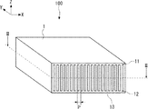
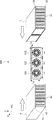
実施の形態1にかかるヒートシンクについて説明する。図1に、実施の形態1にかかるヒートシンク100の外観を模式的に示す。ヒートシンク100は、ヒートシンクブロック1及びファンユニットFUを有する。ヒートシンクブロック1は、2枚のプレート11及び12の間に配列された複数のフィン13を有するものとして構成される。以下では、説明の明確化のため、X軸、Y軸及びZ軸が互いに直交した3次元直交座標系において、ヒートシンクブロック1のそれぞれを構成するプレートの主面を、X−Y平面と平行な面として表している。また、ヒートシンクブロック1のフィン13のそれぞれの主面を、Y−Z平面に平行な面として表している。なお、以下では、X軸、Y軸及びZ軸のそれぞれに沿う方向(X方向、Y方向及びZ方向)を、第1〜第3の方向とも称する。
The heat sink according to the first embodiment will be described. FIG. 1 schematically shows the appearance of the
図2に、図1のII−II線におけるヒートシンク100のX−Y断面を示す。ヒートシンクブロック1では、Z方向に離隔して配置されたプレート11とプレート12との間に、複数のフィン13が、ピッチPの等間隔で、X方向に並んで配列されている。フィン13のうち、ファンユニットFUを収容する部分には切り欠き部が設けられる。これらの切り欠き部によって、ファンユニットFUを収容できる寸法を有する空間である収容部10が構成される。以下では、ファンユニットFUのX方向の寸法をLx、Y方向の寸法をLy、Z方向の寸法をLzとし、収容部10はこの寸法のファンユニットFUを収容可能な容積を有するものとして構成される。
FIG. 2 shows an XY cross section of the
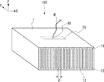
図3に、実施の形態1にかかるヒートシンク100におけるファンユニットFUの収容方法を示す。本構成では、例えば、プレート12とフィン13とが一体として形成されており、上方からファンユニットFUを収容部10に挿入することができる。ファンユニットFUは、送風方向がフィンの長手方向に平行な方向、すなわちY方向となるように収容される。その後、プレート11をフィン13上に被せて、ネジなどの固定手段によって固定することで、ヒートシンク100を作製することができる。
FIG. 3 shows a method of accommodating the fan unit FU in the
なお、ファンユニットFUに接続される配線は、ヒートシンクブロック1に配線引き出し用の孔部を設け、配線をこの孔部に挿通させて引き出してもよい。
For the wiring connected to the fan unit FU, the
図4に、配線引き出し用の孔部の例を示す。この例では、プレート11に孔部H1が設けられ、この孔部H1に配線Wが挿通されている。
FIG. 4 shows an example of a hole for drawing out the wiring. In this example, the
以上、本構成によれば、ファンユニットを内蔵したヒートシンクを提供することができる。ファンユニットがヒートシンクブロックの外部に露出していないので、ヒートシンクの小型化を実現することができる。 As described above, according to this configuration, it is possible to provide a heat sink having a built-in fan unit. Since the fan unit is not exposed to the outside of the heat sink block, the heat sink can be miniaturized.
また、ファンユニットがヒートシンクブロックの外部に露出する一般的なヒートシンクと異なり、単純な外形とすることができるので、装置内におけるヒートシンクの配置の自由度を向上させることができる。 Further, unlike a general heat sink in which the fan unit is exposed to the outside of the heat sink block, the outer shape can be simple, so that the degree of freedom in arranging the heat sink in the apparatus can be improved.
さらに、ファンユニットの送風を効率よくフィンに導くことができるので、ヒートシンクの熱を効率的に放熱することができる。 Further, since the air of the fan unit can be efficiently guided to the fins, the heat of the heat sink can be efficiently dissipated.
なお、上述では収容部の配置位置をヒートシンクブロックの中央としたが、これは例示に過ぎない。必要に応じて、X方向の任意の位置、かつ、Y方向の任意の位置に収容部を設けてもよい。 In the above description, the position of the accommodating portion is set to the center of the heat sink block, but this is merely an example. If necessary, the accommodating portion may be provided at an arbitrary position in the X direction and an arbitrary position in the Y direction.
実施の形態2
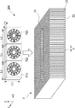
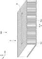
実施の形態2にかかるヒートシンクについて説明する。実施の形態2にかかるヒートシンクは、実施の形態1にかかるヒートシンクの変形例であり、ヒートシンク内に複数のファンユニットを内蔵するものとして構成される。図5に、実施の形態2にかかるヒートシンク200の構成を模式的に示す。ヒートシンク200は、ヒートシンクブロック2及びファンユニットFU1〜FU3を有する。
The heat sink according to the second embodiment will be described. The heat sink according to the second embodiment is a modification of the heat sink according to the first embodiment, and is configured to include a plurality of fan units in the heat sink. FIG. 5 schematically shows the configuration of the
ヒートシンクブロック2は、実施の形態1にかかるヒートシンク100のヒートシンクブロック1に対応するものである。ヒートシンクブロック2は、複数のファンユニットを収容可能に構成される。ここでは、ヒートシンクブロック2が3つのファンユニットFU1〜FU3を収容する例について説明する。
The
ヒートシンクブロック2のプレート21、プレート22、フィン23及び収容部20は、それぞれヒートシンク100のプレート11、プレート12、フィン13及び収容部10に対応する。
The
図6に、図5のVI−VI線におけるヒートシンク200のX−Y断面を示す。図7に、実施の形態2にかかるヒートシンク200におけるファンユニットFU1〜FU3の収容方法を示す。実施の形態1と同様に、ヒートシンクブロック2の収容部20は、3つのファンユニットFU1〜FU3を収容可能な寸法を有するように構成される。ファンユニットFU1〜FU3は、X方向に並んで配列され、かつ、送風方向がフィンの長手方向に平行な方向、すなわちY方向となるように収容される。よって、ヒートシンクブロック2は、収容部20のX方向の寸法が3×Lxよりも大きくなるように構成される。
FIG. 6 shows an XY cross section of the
なお、ファンユニットFU1〜FU3に接続される配線は、実施の形態1で図4を参照して説明した孔部を適宜設け、配線をこの孔部に挿通させて引き出してもよい。 The wiring connected to the fan units FU1 to FU3 may be appropriately provided with a hole described with reference to FIG. 4 in the first embodiment, and the wiring may be inserted through the hole and pulled out.
以上、本構成によれば、複数のファンユニットを内蔵したヒートシンクを提供することができる。これにより、実施の形態1と同様の利点を有する、より大型のヒートシンクを実現することが可能となる。 As described above, according to this configuration, it is possible to provide a heat sink having a plurality of fan units built-in. This makes it possible to realize a larger heat sink having the same advantages as in the first embodiment.
なお、本実施の形態では、X方向に配列された3つのファンユニットが内蔵される構成について説明したが、これは例示に過ぎない。すなわち、ヒートシンクにはX方向に配列された2又は4個以上のファンユニットを内蔵してもよい。 In the present embodiment, a configuration in which three fan units arranged in the X direction are built in has been described, but this is merely an example. That is, the heat sink may include two or four or more fan units arranged in the X direction.
実施の形態3
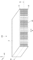
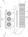
実施の形態3にかかるヒートシンクについて説明する。実施の形態3にかかるヒートシンク300は、実施の形態2にかかるヒートシンク200の変形例であり、ヒートシンクブロックの組み立て後に複数のファンユニットを着脱可能に構成されている。図8に、実施の形態3にかかるヒートシンク300の構成を模式的に示す。
The heat sink according to the third embodiment will be described. The
ヒートシンク300は、ヒートシンクブロック3、カバープレート34及びファンユニットFU1〜FU3を有する。
The
ヒートシンクブロック3のプレート31、プレート32、フィン33及び収容部30は、それぞれヒートシンク200のプレート21、プレート22、フィン23及び収容部20に対応する。
The
図9に、実施の形態3にかかるヒートシンク300におけるファンユニットFU1〜FU3の収容方法を示す。プレート31には、収容部30に対応する位置に開口部OPが設けられている。この開口部OPを通じてファンユニットFU1〜FU3を収容部30に挿入することで、ファンユニットFU1〜FU3が収容部30に収容される。
FIG. 9 shows a method of accommodating the fan units FU1 to FU3 in the
換言すれば、本構成では、プレート31及び32とフィン33とからなるヒートシンクブロック3を組み立てた後でも、ファンユニットの着脱が可能である。
In other words, in this configuration, the fan unit can be attached and detached even after the
ファンユニットFU1〜FU3が収容部30に収容された状態で、開口部OPはカバープレート34によって閉塞される。カバープレート34は、適宜、ネジなどの固定手段によってヒートシンクブロック3に固定することができる。これにより、ファンユニットFU1〜FU3がヒートシンクブロック3から脱落することを防止するとともに、ファンユニットFU1〜FU3からの送風が開口部OPから漏れ出すことも防止できる。
With the fan units FU1 to FU3 housed in the
なお、ファンユニットFU1〜FU3に接続される配線は、例えばカバープレート34に、実施の形態1で図4を参照して説明した孔部を適宜設け、配線をこの孔部に挿通させて引き出してもよい。
For the wiring connected to the fan units FU1 to FU3, for example, the
以上、本構成によれば、実施の形態1及び2と同様に、ファンユニットを内蔵したヒートシンクを提供することができる。これにより、これにより、実施の形態1及び2と同様の利点を有するとともに、より容易に作製できるヒートシンクを実現することが可能となる。 As described above, according to this configuration, it is possible to provide a heat sink having a built-in fan unit, as in the first and second embodiments. As a result, it is possible to realize a heat sink which has the same advantages as those of the first and second embodiments and can be manufactured more easily.
また、本構成によれば、ヒートシンクブロックを分解することなく、ファンユニットを容易に着脱、すなわち、取り付け及び取り外しを行うことができる。よって、用途に合わせてファンユニットを交換したり、故障したファンユニットを健全なファンユニットに置換することが可能である。 Further, according to this configuration, the fan unit can be easily attached / detached, that is, attached / detached without disassembling the heat sink block. Therefore, it is possible to replace the fan unit or replace the failed fan unit with a sound fan unit according to the application.
実施の形態4
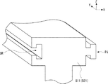
実施の形態4にかかるヒートシンクについて説明する。実施の形態4にかかるヒートシンクは、実施の形態2にかかるヒートシンク200の変形例であり、ヒートシンクブロックが複数に分割された構成を有する。図10に、実施の形態4にかかるヒートシンク400の構成を模式的に示す。ヒートシンク400は、ヒートシンクブロック4、ヒートシンクブロック5及びファンユニットFU1〜FU3を有する。
The heat sink according to the fourth embodiment will be described. The heat sink according to the fourth embodiment is a modification of the
本構成では、ヒートシンクブロック4及び5は、X方向に並んで配置されて連結されることで、実施の形態2のヒートシンクブロック2と同様のヒートシンクブロックを構成する。なお、ヒートシンクブロック4及び5の一方を第1のヒートシンクブロックとも称し、他方を第2のヒートシンクブロックとも称する。
In this configuration, the heat sink blocks 4 and 5 are arranged side by side in the X direction and connected to form a heat sink block similar to the
ヒートシンクブロック4では、Z方向に離隔して配置されたプレート41とプレート42との間に、複数のフィン43が、ピッチPの等間隔で、X方向に並んで配列されている。フィン43のうち、ヒートシンクブロック5の側に配列される一部のものには、ファンユニットFU1〜FU3を収容するための切り欠き部44が設けられる。
In the
ヒートシンクブロック5では、Z方向に離隔して配置されたプレート51とプレート52との間に、複数のフィン53が、ピッチPの等間隔で、X方向に並んで配列されている。フィン53のうち、ヒートシンクブロック4の側に配列される一部のものには、ファンユニットFU1〜FU3を収容するための切り欠き部54が設けられる。
In the
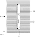
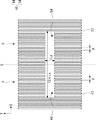
図11に、図10のXI−XI線におけるヒートシンク400のX−Y断面を示す。ヒートシンクブロック4及び5は、切り欠き部44と切り欠き部54とが対向するように配列される。これにより、切り欠き部44及び54Dは、一体としてファンユニットFU1〜FU3を収容可能な寸法を有する、実施の形態2における収容部20と同様の収容部40を構成する。
FIG. 11 shows an XY cross section of the
この例では、ヒートシンクブロック4及び5は、それぞれ、図11の線Lに対して対称な形状となるように構成される。すなわち、切り欠き部44及び54は、同じ容積を有している。
In this example, the heat sink blocks 4 and 5 are respectively configured to have a symmetrical shape with respect to the line L in FIG. That is, the
ファンユニットFU1〜FU3は、ヒートシンクブロック4とヒートシンクブロック5とを接合する前に、収容部40に挿入される。図12に、実施の形態4にかかるヒートシンク400におけるファンユニットFU1〜FU3の収容方法を示す。ファンユニットFU1〜FU3を切り欠き部44と切り欠き部54とで挟み込んで、ヒートシンクブロック4及び5を互いに接近させて連結することで、収容部40にファンユニットFU1〜FU2を収容することができる。なお、ヒートシンクブロック4とヒートシンクブロック5との連結は、ネジなどの各種の固定手段を用いることが可能である。
The fan units FU1 to FU3 are inserted into the
なお、ファンユニットFU1〜FU3に接続される配線は、ヒートシンクブロック4とヒートシンクブロック5の接合部のプレートに配線引き出し用の孔部を設け、配線をこの孔部に挿通させて引き出してもよい。
For the wiring connected to the fan units FU1 to FU3, a hole for drawing out the wiring may be provided in the plate of the joint portion between the
また、本実施の形態では収容部40がヒートシンク4及び5に2分割されて構成されるものとして説明したが、収容部40はヒートシンク4及び5の一方にのみ設けられてもよい。
Further, in the present embodiment, the
以上、本構成によれば、複数のファンユニットを内蔵したヒートシンクを提供することができる。これにより、実施の形態2と同様の利点を有する、大型のヒートシンクを実現することが可能となる。 As described above, according to this configuration, it is possible to provide a heat sink having a plurality of fan units built-in. This makes it possible to realize a large heat sink having the same advantages as in the second embodiment.
実施の形態5
実施の形態5にかかるヒートシンクについて説明する。実施の形態5にかかるヒートシンク500では、ヒートシンクブロックが複数のユニットプレートを組み合わせることで構成される。図13に、実施の形態5にかかるヒートシンク500の構成を模式的に示す。
The heat sink according to the fifth embodiment will be described. In the
ヒートシンク500は、実施の形態1にかかるヒートシンク300のヒートシンクブロック3を、ヒートシンクブロック6に置換した構成を有する。ヒートシンク500のその他の構成は、ヒートシンク300と同様である。
The
ヒートシンク500のヒートシンクブロック6は、ユニットプレートPL1及びユニットプレートPL2で構成される。
The heat sink block 6 of the
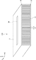
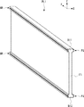
図14に、ユニットプレートPL1の構成を示す。ユニットプレートPL1は、Z方向に離隔して配置されたY方向に延在する2本のビームB11及びB12と、ビームB11とビームB12との間に設けられたY−Z平面を主面とするフィンF1とで構成される。なお、ビームB11及びB12の一方を第1のビームとも称し、他方を第2のビームとも称する。 FIG. 14 shows the configuration of the unit plate PL1. The unit plate PL1 has two beams B11 and B12 extending in the Y direction arranged apart from each other in the Z direction and a YZ plane provided between the beams B11 and the beam B12 as main surfaces. It is composed of fins F1. One of the beams B11 and B12 is also referred to as a first beam, and the other is also referred to as a second beam.
図15に、ユニットプレートPL2の構成を示す。ユニットプレートPL2は、Z方向に離隔して配置されたY方向に延在する2本のビームB21及びB22と、ビームB21とビームB22との間に設けられたY−Z平面を主面とするフィンF2とで構成される。ユニットプレートPL2では、ユニットプレートPL1と異なり、フィンF2の中央部に、ファンユニットを収容するための切り欠き部Cが設けられる。なお、ビームB21及びB22の一方を第1のビームとも称し、他方を第2のビームとも称する。 FIG. 15 shows the configuration of the unit plate PL2. The unit plate PL2 has two beams B21 and B22 extending in the Y direction arranged apart from each other in the Z direction and a YZ plane provided between the beams B21 and the beam B22 as main surfaces. It is composed of fins F2. In the unit plate PL2, unlike the unit plate PL1, a notch portion C for accommodating the fan unit is provided in the central portion of the fin F2. One of the beams B21 and B22 is also referred to as a first beam, and the other is also referred to as a second beam.
ユニットプレートPL1及びPL2のビームのそれぞれは、隣接するユニットプレートと連結するための機構が設けられる。以下、具体例について説明する。図16に、ユニットプレートの部分拡大図を示す。 Each of the beams of the unit plates PL1 and PL2 is provided with a mechanism for connecting to adjacent unit plates. A specific example will be described below. FIG. 16 shows a partially enlarged view of the unit plate.
ユニットプレートPL1及びPL2のビームのX(−)側には、T字型の溝GRが設けられている。溝GRは、Z−X平面において90°横倒しにしたT字型の中空部を有する溝として、ビームをY方向に貫通するように設けられる。 A T-shaped groove GR is provided on the X (−) side of the beams of the unit plates PL1 and PL2. The groove GR is provided so as to penetrate the beam in the Y direction as a groove having a T-shaped hollow portion that is laid down 90 ° in the ZX plane.
各ユニットプレートのビームのX(+)側には、T字型の突出部PJが設けられている。突出部PJは、Z−X平面において90°横倒しにしたT字型の突出部を有するものとして、ビームのX(+)側の面上でY方向に延在するように設けられる。 A T-shaped protrusion PJ is provided on the X (+) side of the beam of each unit plate. The projecting portion PJ is provided so as to have a T-shaped projecting portion that is tilted 90 ° in the ZX plane so as to extend in the Y direction on the surface on the X (+) side of the beam.
よって、例えば、2つのユニットプレートの一方の溝GRのY(+)側の端部と、他方の突出部PJのY(−)側の端部とを嵌合させて、その後2つのユニットプレートをY方向に沿って互いに逆方向にスライドさせることで、突出部PJ全体が溝GRに嵌まり込む。これによって、2つのユニットプレートが互いに連結される。図17に、連結されたユニットプレートの連結部の拡大図を示す。この連結作業を複数回繰り返すことで、図17に示すように、ヒートシンクブロック6を構成することができる。 Therefore, for example, the Y (+) side end of one groove GR of the two unit plates and the Y (-) side end of the other protruding portion PJ are fitted, and then the two unit plates are fitted. Is slid in opposite directions along the Y direction, so that the entire protruding portion PJ fits into the groove GR. This connects the two unit plates to each other. FIG. 17 shows an enlarged view of the connecting portion of the connected unit plates. By repeating this connecting operation a plurality of times, the heat sink block 6 can be configured as shown in FIG.
収容部40に対応する位置ではユニットプレートPL2を連結し、かつ、その他の位置ではユニットプレートPL1を連結することで、ヒートシンクブロック3と同様の構成を有するヒートシンクブロック6を実現できることが理解できる。
It can be understood that the heat sink block 6 having the same configuration as the
なお、ファンユニットの収容については、実施の形態3で図9を参照して説明したのと同様であるので、説明を省略する。 The accommodation of the fan unit is the same as that described with reference to FIG. 9 in the third embodiment, and thus the description thereof will be omitted.
以上、本構成によれば、複数のファンユニットを内蔵したヒートシンクを提供することができる。これにより、実施の形態3と同様の利点を有する、大型のヒートシンクを実現することが可能となる。 As described above, according to this configuration, it is possible to provide a heat sink having a plurality of fan units built-in. This makes it possible to realize a large heat sink having the same advantages as in the third embodiment.
また、本構成によれば、連結するユニットプレートを適宜選択することで、必要に応じて、内蔵するファンユニットの数の変更や、ヒートシンクブロックの寸法の変更に対応することが可能となる。また、予めユニットプレートを準備しておくことで、任意の数のファンユニット及び寸法に対応可能なヒートシンクを容易に作製することができる。これにより、実施の形態1〜4と比べて、ヒートシンクの設計により柔軟に対応することが可能となる。 Further, according to this configuration, by appropriately selecting the unit plates to be connected, it is possible to change the number of built-in fan units and the dimensions of the heat sink block as needed. Further, by preparing the unit plate in advance, it is possible to easily manufacture a heat sink capable of corresponding to an arbitrary number of fan units and dimensions. As a result, it becomes possible to flexibly deal with the design of the heat sink as compared with the first to fourth embodiments.
その他の実施の形態
なお、本発明は上記実施の形態に限られたものではなく、趣旨を逸脱しない範囲で適宜変更することが可能である。例えば、実施の形態3〜5では、X方向配列された3つのファンユニットが内蔵される構成について説明したが、これは例示に過ぎない。すなわち、ヒートシンクには、1個、又は、X方向に配列された2個又は4個以上のファンユニットを内蔵してもよい。
Other Embodiments The present invention is not limited to the above embodiments, and can be appropriately modified without departing from the spirit. For example, in the third to fifth embodiments, the configuration in which the three fan units arranged in the X direction are incorporated has been described, but this is merely an example. That is, the heat sink may contain one fan unit or two or four or more fan units arranged in the X direction.
ヒートシンクブロックやカバープレートを構成する材料としては、アルミニウム、鉄、銅などの高い電熱特性を有する金蔵材料を用いることがのぞましい。なお、ここでいう金属材料は、純金属だけでなく合金を含むことは言うまでもない。また、用途によっては、セラミックスなどの非金属材料を用いてもよい。 As a material for forming the heat sink block and the cover plate, it is desirable to use a gold storage material having high electric heating characteristics such as aluminum, iron, and copper. Needless to say, the metal material referred to here includes not only pure metals but also alloys. Further, depending on the application, a non-metallic material such as ceramics may be used.
上述の実施の形態では、ヒートシンクに収容部が1つ設けられているが、これは便宜上のものに過ぎず、1つのヒートシンクに複数の収容部を設け、各収容部に1以上のファンユニットを収容してもよい。この場合、複数の収容部は、それぞれX−Y平面内の異なる位置に設けてもよい。 In the above-described embodiment, the heat sink is provided with one accommodating portion, but this is for convenience only. A plurality of accommodating portions are provided in one heat sink, and one or more fan units are provided in each accommodating portion. May be accommodated. In this case, the plurality of accommodating portions may be provided at different positions in the XY plane.
B11、B12、B21、B22 ビーム
PL1、PL2 ユニットプレート
C 切り欠き部
F1、F2 フィン
FU、FU1〜FU3 ファンユニット
GR 溝
H1 孔部
OP 開口部
PJ 突出部
W 配線
1〜6 ヒートシンクブロック
10、20、30、40 収容部
11、12、21、22、31、32、41、42 プレート
13、23、33、43 フィン
34 カバープレート
44、54 切り欠き部
100、200、300、400、500 ヒートシンク
B11, B12, B21, B22 Beam PL1, PL2 Unit plate C Notch F1, F2 Fin FU, FU1 to FU3 Fan unit GR Groove H1 Hole OP Opening PJ
Claims (6)
前記2枚のプレートの間で、前記2枚のプレートの主面に対して平行な方向である第1の方向に配列された、前記第1の方向に直交し、かつ、前記2枚のプレートの主面に対して平行な第2の方向に延在する、複数のフィンと、
前記複数のフィンの一部に設けられた切り欠き部からなる収容部と、
前記第2の方向に送風する、前記収容部に収容されたファンユニットと、
カバープレートと、を備え、
前記2枚のプレートの一方又は両方には、前記収容部に対応する位置に開口部が設けられ、
前記ファンユニットは、前記開口部を介して前記収容部に挿入可能であり、かつ、前記開口部を介して前記収容部から取り出し可能であり、
前記カバープレートは、前記収容部に前記ファンユニットを収容した状態で、前記開口部を覆う、
ヒートシンク。 Two plates arranged in parallel so that the main surfaces face each other,
Between the two plates, the two plates are arranged in a first direction parallel to the main surface of the two plates, orthogonal to the first direction, and the two plates. With multiple fins extending in a second direction parallel to the main surface of the
An accommodating portion composed of notches provided in a part of the plurality of fins,
A fan unit housed in the housing unit that blows air in the second direction ,
For example Bei and the cover plate, the,
One or both of the two plates is provided with an opening at a position corresponding to the accommodating portion.
The fan unit can be inserted into the housing portion through the opening and can be taken out from the housing portion through the opening.
The cover plate covers the opening with the fan unit housed in the housing.
heat sink.
請求項1に記載のヒートシンク。 A plurality of the fan units arranged in the first direction are accommodated in the accommodating portion.
The heat sink according to claim 1.
前記第1及び第2の方向に直交する第3の方向に離隔された、前記第2の方向に延在する第1及び第2のビームと、前記第1のビームと前記第2のビームとの間に設けられた、前記複数のフィンのうちの1つのフィンと、を備えるユニットプレートを、前記第1の方向に複数個連結することで構成され、
連結された前記第1のビームが、前記2枚のプレートの一方を構成し、
連結された前記第2のビームが、前記2枚のプレートの他方を構成する、
請求項1又は2に記載のヒートシンク。 The heat sink block composed of the two plates, the plurality of fins, and the housing portion is
The first and second beams extending in the second direction, separated in a third direction orthogonal to the first and second directions, and the first beam and the second beam. It is configured by connecting a plurality of unit plates provided between the above-mentioned fins and one of the plurality of fins in the first direction.
The connected first beam constitutes one of the two plates.
The connected second beam constitutes the other of the two plates.
The heat sink according to claim 1 or 2.
請求項3に記載のヒートシンク。 Of the plurality of connected unit plates, the fins at positions corresponding to the accommodating portions are provided with the notch portions.
The heat sink according to claim 3.
前記2枚のプレートの間で、前記2枚のプレートの主面に対して平行な方向である第1の方向に配列された、前記第1の方向に直交し、かつ、前記2枚のプレートの主面に対して平行な第2の方向に延在する、複数のフィンと、
前記複数のフィンの一部に設けられた切り欠き部からなる収容部と、
前記第2の方向に送風する、前記収容部に収容されたファンユニットと、を備え、
前記2枚のプレート、前記複数のフィン及び前記収容部からなるヒートシンクブロックは、前記第1の方向に配列される第1のヒートシンクブロックと第2のヒートシンクブロックとに分割されて構成され、
前記収容部の一部は前記第1のヒートシンクブロックに形成され、前記収容部の他の一部は前記第2のヒートシンクブロックに形成され、前記第1のヒートシンクブロックと前記第2のヒートシンクブロックとを連結することで前記収容部が構成され、又は、
前記収容部は前記第1及び第2のヒートシンクブロックの一方に形成される、
ヒートシンク。 Two plates arranged in parallel so that the main surfaces face each other,
Between the two plates, the two plates are arranged in a first direction parallel to the main surface of the two plates, orthogonal to the first direction, and the two plates. With multiple fins extending in a second direction parallel to the main surface of the
An accommodating portion composed of notches provided in a part of the plurality of fins,
A fan unit housed in the housing unit, which blows air in the second direction, is provided.
The heat sink block composed of the two plates, the plurality of fins, and the housing portion is divided into a first heat sink block and a second heat sink block arranged in the first direction.
A part of the accommodating portion is formed in the first heat sink block, and the other part of the accommodating portion is formed in the second heat sink block, and the first heat sink block and the second heat sink block By connecting the above-mentioned accommodating portions, or
The accommodating portion is formed on one of the first and second heat sink blocks.
Heat sink .
請求項5に記載のヒートシンク。 A plurality of the fan units arranged in the first direction are accommodated in the accommodating portion.
The heat sink according to claim 5.
Priority Applications (1)
| Application Number | Priority Date | Filing Date | Title |
|---|---|---|---|
| JP2019171147A JP6830686B1 (en) | 2019-09-20 | 2019-09-20 | heat sink |
Applications Claiming Priority (1)
| Application Number | Priority Date | Filing Date | Title |
|---|---|---|---|
| JP2019171147A JP6830686B1 (en) | 2019-09-20 | 2019-09-20 | heat sink |
Publications (2)
| Publication Number | Publication Date |
|---|---|
| JP6830686B1 true JP6830686B1 (en) | 2021-02-17 |
| JP2021048342A JP2021048342A (en) | 2021-03-25 |
Family
ID=74562356
Family Applications (1)
| Application Number | Title | Priority Date | Filing Date |
|---|---|---|---|
| JP2019171147A Active JP6830686B1 (en) | 2019-09-20 | 2019-09-20 | heat sink |
Country Status (1)
| Country | Link |
|---|---|
| JP (1) | JP6830686B1 (en) |
Family Cites Families (12)
| Publication number | Priority date | Publication date | Assignee | Title |
|---|---|---|---|---|
| JPH062312Y2 (en) * | 1988-05-13 | 1994-01-19 | 日本電気株式会社 | heatsink |
| JPH0750494A (en) * | 1993-08-06 | 1995-02-21 | Mitsubishi Electric Corp | Cooling system |
| JPH1174429A (en) * | 1997-06-27 | 1999-03-16 | Showa Alum Corp | Radiator |
| JP3524444B2 (en) * | 1999-10-21 | 2004-05-10 | 古河電気工業株式会社 | Cooling device for electronic device and cooling method |
| JP2001210766A (en) * | 2000-01-21 | 2001-08-03 | Tousui Ltd | Heat sink |
| JP2002305273A (en) * | 2001-04-05 | 2002-10-18 | Pfu Ltd | Heat sink device |
| TW577585U (en) * | 2002-12-24 | 2004-02-21 | Delta Electronics Inc | Multi-level heat-dissipating device |
| KR20060070176A (en) * | 2004-12-20 | 2006-06-23 | 삼성전자주식회사 | Cooling device and liquid crystal display including the same |
| CN2854803Y (en) * | 2005-07-21 | 2007-01-03 | 国格金属科技股份有限公司 | Heat sink structure |
| CN101072489B (en) * | 2006-05-10 | 2010-09-08 | 建准电机工业股份有限公司 | Composite cooling module |
| KR20160109507A (en) * | 2015-03-11 | 2016-09-21 | 주식회사 고아정공 | Fan integrated housing |
| CN107023499B (en) * | 2016-01-29 | 2020-04-24 | 台达电子工业股份有限公司 | Fan and heat dissipation device |
-
2019
- 2019-09-20 JP JP2019171147A patent/JP6830686B1/en active Active
Also Published As
| Publication number | Publication date |
|---|---|
| JP2021048342A (en) | 2021-03-25 |
Similar Documents
| Publication | Publication Date | Title |
|---|---|---|
| US20200077532A1 (en) | Electronic apparatus and method for producing electronic apparatus | |
| US9578781B2 (en) | Heat management for electronic enclosures | |
| CN107443421B (en) | Motor unit and robot | |
| US20200236811A1 (en) | Thermally conductive insert element for electronic unit | |
| JP6830686B1 (en) | heat sink | |
| JP2016063200A (en) | Substrate mounting structure and power supply device | |
| JP6061049B1 (en) | Power conversion device and power conversion system | |
| US10602604B2 (en) | Electronic component unit | |
| JP2019022293A (en) | Power supply | |
| JP2017177088A (en) | Irradiation unit and irradiation device | |
| JP7660367B2 (en) | Cooling structure and electronic device | |
| WO2018061814A1 (en) | Power supply device | |
| JP2018195844A (en) | heatsink | |
| JP7074270B1 (en) | Semiconductor device | |
| JP2020072161A (en) | Heat sink | |
| WO2019159776A1 (en) | Cooling device | |
| US8726505B2 (en) | Heat sinking methods for performance and scalability | |
| US20180056508A1 (en) | Motor unit and robot | |
| CN222424553U (en) | Power Module | |
| JP2008311467A (en) | Power module | |
| US10971899B2 (en) | Laser light source unit | |
| CN118317576A (en) | Power Module | |
| JP2017055520A (en) | Power supply device and method of manufacturing the same | |
| JP2009076623A (en) | Electronics | |
| TW201102742A (en) | Optical projection system |
Legal Events
| Date | Code | Title | Description |
|---|---|---|---|
| A621 | Written request for application examination |
Free format text: JAPANESE INTERMEDIATE CODE: A621 Effective date: 20190925 |
|
| A131 | Notification of reasons for refusal |
Free format text: JAPANESE INTERMEDIATE CODE: A131 Effective date: 20201104 |
|
| A521 | Request for written amendment filed |
Free format text: JAPANESE INTERMEDIATE CODE: A523 Effective date: 20201221 |
|
| TRDD | Decision of grant or rejection written | ||
| A01 | Written decision to grant a patent or to grant a registration (utility model) |
Free format text: JAPANESE INTERMEDIATE CODE: A01 Effective date: 20210105 |
|
| A61 | First payment of annual fees (during grant procedure) |
Free format text: JAPANESE INTERMEDIATE CODE: A61 Effective date: 20210113 |
|
| R150 | Certificate of patent or registration of utility model |
Ref document number: 6830686 Country of ref document: JP Free format text: JAPANESE INTERMEDIATE CODE: R150 |
|
| R250 | Receipt of annual fees |
Free format text: JAPANESE INTERMEDIATE CODE: R250 |
|
| R250 | Receipt of annual fees |
Free format text: JAPANESE INTERMEDIATE CODE: R250 |
|
| R250 | Receipt of annual fees |
Free format text: JAPANESE INTERMEDIATE CODE: R250 |