JP6830386B2 - Measuring head - Google Patents
Measuring head Download PDFInfo
- Publication number
- JP6830386B2 JP6830386B2 JP2017061952A JP2017061952A JP6830386B2 JP 6830386 B2 JP6830386 B2 JP 6830386B2 JP 2017061952 A JP2017061952 A JP 2017061952A JP 2017061952 A JP2017061952 A JP 2017061952A JP 6830386 B2 JP6830386 B2 JP 6830386B2
- Authority
- JP
- Japan
- Prior art keywords
- slider
- measurement
- measuring head
- posture
- guide
- Prior art date
- Legal status (The legal status is an assumption and is not a legal conclusion. Google has not performed a legal analysis and makes no representation as to the accuracy of the status listed.)
- Expired - Fee Related
Links
- 238000005259 measurement Methods 0.000 claims description 127
- 239000012530 fluid Substances 0.000 claims description 42
- 239000000523 sample Substances 0.000 claims description 34
- 238000001514 detection method Methods 0.000 claims description 6
- 230000007246 mechanism Effects 0.000 description 36
- 230000001105 regulatory effect Effects 0.000 description 7
- 230000005484 gravity Effects 0.000 description 6
- 230000008859 change Effects 0.000 description 3
- 238000000034 method Methods 0.000 description 3
- 230000004048 modification Effects 0.000 description 3
- 238000012986 modification Methods 0.000 description 3
- 241001422033 Thestylus Species 0.000 description 2
- 230000000694 effects Effects 0.000 description 2
- 230000001771 impaired effect Effects 0.000 description 2
- 230000004044 response Effects 0.000 description 2
- 238000010586 diagram Methods 0.000 description 1
- 230000002708 enhancing effect Effects 0.000 description 1
- 230000006872 improvement Effects 0.000 description 1
- 238000000691 measurement method Methods 0.000 description 1
Images


Classifications
-
- G—PHYSICS
- G01—MEASURING; TESTING
- G01B—MEASURING LENGTH, THICKNESS OR SIMILAR LINEAR DIMENSIONS; MEASURING ANGLES; MEASURING AREAS; MEASURING IRREGULARITIES OF SURFACES OR CONTOURS
- G01B21/00—Measuring arrangements or details thereof, where the measuring technique is not covered by the other groups of this subclass, unspecified or not relevant
- G01B21/02—Measuring arrangements or details thereof, where the measuring technique is not covered by the other groups of this subclass, unspecified or not relevant for measuring length, width, or thickness
- G01B21/06—Measuring arrangements or details thereof, where the measuring technique is not covered by the other groups of this subclass, unspecified or not relevant for measuring length, width, or thickness specially adapted for measuring length or width of objects while moving
-
- G—PHYSICS
- G01—MEASURING; TESTING
- G01B—MEASURING LENGTH, THICKNESS OR SIMILAR LINEAR DIMENSIONS; MEASURING ANGLES; MEASURING AREAS; MEASURING IRREGULARITIES OF SURFACES OR CONTOURS
- G01B21/00—Measuring arrangements or details thereof, where the measuring technique is not covered by the other groups of this subclass, unspecified or not relevant
- G01B21/02—Measuring arrangements or details thereof, where the measuring technique is not covered by the other groups of this subclass, unspecified or not relevant for measuring length, width, or thickness
- G01B21/04—Measuring arrangements or details thereof, where the measuring technique is not covered by the other groups of this subclass, unspecified or not relevant for measuring length, width, or thickness by measuring coordinates of points
- G01B21/047—Accessories, e.g. for positioning, for tool-setting, for measuring probes
-
- G—PHYSICS
- G01—MEASURING; TESTING
- G01B—MEASURING LENGTH, THICKNESS OR SIMILAR LINEAR DIMENSIONS; MEASURING ANGLES; MEASURING AREAS; MEASURING IRREGULARITIES OF SURFACES OR CONTOURS
- G01B13/00—Measuring arrangements characterised by the use of fluids
- G01B13/02—Measuring arrangements characterised by the use of fluids for measuring length, width or thickness
- G01B13/03—Measuring arrangements characterised by the use of fluids for measuring length, width or thickness by measuring coordinates of points
-
- G—PHYSICS
- G01—MEASURING; TESTING
- G01B—MEASURING LENGTH, THICKNESS OR SIMILAR LINEAR DIMENSIONS; MEASURING ANGLES; MEASURING AREAS; MEASURING IRREGULARITIES OF SURFACES OR CONTOURS
- G01B5/00—Measuring arrangements characterised by the use of mechanical techniques
- G01B5/004—Measuring arrangements characterised by the use of mechanical techniques for measuring coordinates of points
- G01B5/008—Measuring arrangements characterised by the use of mechanical techniques for measuring coordinates of points using coordinate measuring machines
-
- G—PHYSICS
- G01—MEASURING; TESTING
- G01B—MEASURING LENGTH, THICKNESS OR SIMILAR LINEAR DIMENSIONS; MEASURING ANGLES; MEASURING AREAS; MEASURING IRREGULARITIES OF SURFACES OR CONTOURS
- G01B9/00—Measuring instruments characterised by the use of optical techniques
- G01B9/02—Interferometers
- G01B9/02049—Interferometers characterised by particular mechanical design details
- G01B9/0205—Interferometers characterised by particular mechanical design details of probe head
Landscapes
- Physics & Mathematics (AREA)
- General Physics & Mathematics (AREA)
- A Measuring Device Byusing Mechanical Method (AREA)
- Length Measuring Devices With Unspecified Measuring Means (AREA)
- Fluid Mechanics (AREA)
- Engineering & Computer Science (AREA)
- Automation & Control Theory (AREA)
Description
本発明は、ワーク表面を測定対象とする測定ヘッドに関し、特に、測定ヘッドに内蔵されたモータ動力の補助機構の改良に関する。 The present invention relates to a measuring head whose measurement target is a work surface, and more particularly to an improvement of a motor power assisting mechanism built in the measuring head.
ワークの表面形状のうち、高い精度が要求される測定領域と、比較的低い精度であっても許容される測定領域と、の両方を含んでいるワークを測定する場合に適した三次元測定機が知られている(特許文献1参照)。これは、門型のCNC三次元座標測定機と、この測定機によって3軸方向に移動可能に設けられた測定ヘッドとを組み合せた構造である。 A three-dimensional measuring machine suitable for measuring a workpiece that includes both a measurement region that requires high accuracy and a measurement region that allows even relatively low accuracy among the surface shapes of the workpiece. Is known (see Patent Document 1). This is a structure in which a gate-type CNC three-dimensional coordinate measuring machine and a measuring head provided by the measuring machine so as to be movable in three axial directions are combined.
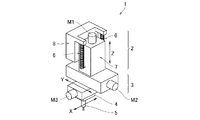
門型の三次元測定機は、ベースと、このベースの上面に水平方向へ移動可能に設けられたX軸テーブルと、ベースに立設されたコラムと、このコラムに支持されたビームと、ビームに沿って移動可能に設けられたY軸スライダと、このY軸スライダに昇降可能に設けられたZ軸スライダと、このZ軸スライダに連結されたスピンドルとを備えたものが一般的であり、特許文献1ではスピンドルの先端に測定ヘッドを取付けたことに特徴がある。測定ヘッド1は、図7のように、三次元測定機のスピンドルの先端に着脱可能に設けられたZ軸スライド機構2と、これによってZ軸方向に移動可能に支持されたY軸スライド機構3と、これによってY軸方向に移動可能に支持されたX軸スライド機構4と、このX軸スライド機構4によってX軸方向に移動可能に支持されたプローブ5とを備えた構成である。
The gate-type coordinate measuring machine has a base, an X-axis table that can be moved horizontally on the upper surface of the base, a column that stands on the base, a beam supported by this column, and a beam. Generally, a Y-axis slider provided so as to be movable along the Y-axis slider, a Z-axis slider provided so as to be movable up and down on the Y-axis slider, and a spindle connected to the Z-axis slider are provided. Patent Document 1 is characterized in that a measuring head is attached to the tip of a spindle. As shown in FIG. 7, the measuring head 1 has a Z-
特許文献1によれば、測定ヘッドの駆動機構2〜4がプローブ5を移動させることで、小さい領域での高精度測定が行われ、三次元測定機の駆動機構が測定ヘッド1を移動させることで、大きい領域での低〜中程度の精度による測定がスムーズに行われる。
According to Patent Document 1, the
図7のように、従来の測定ヘッドのZ軸スライド機構2には、略鉛直方向に伸縮するバネ6が設けられ、スライダ7とガイド8を連結している。これは、Z軸スライド機構の動力源である電動モータM1がスライダ7を上昇させる場合に、そのモータへの負荷を軽減し、鉛直方向のモータ駆動性能(位置決め、一定速度、高速移動など)を高めるためのもので、ここでは、モータ動力の補助機構と呼ぶ。
As shown in FIG. 7, the Z-
しかしながら、図7のバネによるモータ動力の補助機構は、Z軸スライダ7の移動方向が略鉛直になるように測定ヘッドの姿勢が定まっていないと、適切に機能しない。また、測定中も測定ヘッドの姿勢が一定であることを要する。測定姿勢を変えると、Y軸又はX軸スライド機構の駆動用モータM2,M3の負荷が変化してしまい、各モータの駆動性能が維持されないからである。また、駆動性能を維持するには姿勢変更の都度、各モータのゲイン調整をやり直す必要がある。 However, the auxiliary mechanism of the motor power by the spring of FIG. 7 does not function properly unless the posture of the measuring head is determined so that the moving direction of the Z-axis slider 7 is substantially vertical. Further, it is necessary that the posture of the measuring head is constant even during the measurement. This is because if the measurement posture is changed, the load of the drive motors M2 and M3 of the Y-axis or X-axis slide mechanism changes, and the drive performance of each motor is not maintained. In addition, in order to maintain the drive performance, it is necessary to readjust the gain of each motor each time the attitude is changed.
測定姿勢に制約があることは特許文献1のように使用される測定ヘッドに限られたものではなく、何らかの移動装置に取り付けて使用される測定ヘッド全般に共通する。発明者らはこのような測定姿勢の制限を取り除くべく、鋭意研究に取り組んできた。 The limitation on the measuring posture is not limited to the measuring head used as in Patent Document 1, but is common to all measuring heads used by being attached to some moving device. The inventors have been working diligently to remove such restrictions on the measurement posture.
本発明は、上記課題を解決するもので、従来の測定ヘッドに内蔵された駆動用モータ動力の補助機構を改良して、測定姿勢に依存しないモータ駆動特性を発揮し、任意の姿勢で測定可能な測定ヘッドを提供することを目的とする。 The present invention solves the above-mentioned problems, and improves the auxiliary mechanism of the drive motor power built in the conventional measurement head to exhibit motor drive characteristics independent of the measurement posture, and can measure in any posture. It is an object of the present invention to provide a flexible measuring head.
すなわち、本発明の測定ヘッドは、
第1測定軸用の第1スライダ、案内用の第1ガイド、及び、駆動用の第1モータと、
前記第1測定軸と平行でない第2測定軸用の第2スライダ、前記第1スライダに固定された案内用の第2ガイド、及び、駆動用の第2モータと、
前記第2スライダに保持されたワーク検知用のプローブと、
を備え、前記各スライダの移動に伴って前記プローブにワーク表面を検出させる測定ヘッドであって、
該測定ヘッドは、外部の任意の移動装置に前記第1ガイドを介して着脱可能であり、
前記第1スライダと前記第1ガイドを接続し前記第1測定軸方向に伸縮自在の第1流体圧シリンダと、
前記第2スライダと前記第2ガイドを接続し前記第2測定軸方向に伸縮自在の第2流体圧シリンダと、
該測定ヘッドの測定姿勢に応じて、前記第1流体圧シリンダ及び前記第2流体圧シリンダへ供給する流体の圧力を変更する第1流体圧変更手段および第2流体圧変更手段と、
を備えることを特徴とする。
That is, the measuring head of the present invention
A first slider for the first measurement axis, a first guide for guidance, and a first motor for driving,
A second slider for the second measurement axis that is not parallel to the first measurement axis, a second guide for guidance fixed to the first slider, and a second motor for driving.
The work detection probe held by the second slider and
A measurement head that causes the probe to detect the work surface as the slider moves.
The measuring head can be attached to and detached from any external moving device via the first guide.
A first fluid pressure cylinder that connects the first slider and the first guide and expands and contracts in the first measurement axis direction.
A second fluid pressure cylinder that connects the second slider and the second guide and expands and contracts in the second measurement axis direction.
A first fluid pressure changing means and a second fluid pressure changing means for changing the pressure of the fluid supplied to the first fluid pressure cylinder and the second fluid pressure cylinder according to the measurement posture of the measuring head.
It is characterized by having.
本発明の測定ヘッドの作用を説明する。測定ヘッドは、門型の三次元測定機(図2)や多関節型の移動装置(図5)などに取り付けられる。このような外部の移動装置によって、測定ヘッドの測定姿勢が任意に設定され、かつ、測定ヘッドが所望の位置に移動した状態で、プローブが各測定軸方向にスライドしてワーク表面を検知する。測定ヘッドは、ワーク表面を検知した際の各測定軸のスライダの移動量に基づいて、ワーク表面の位置情報を取得する。なお、測定ヘッドの測定軸は2軸以上あればよい。例えば、第1測定軸に沿ってプローブをワークに接近・離間させ、第2測定軸に沿ってプローブを次の測定位置に移動させるという方法であれば、外部の移動装置に保持された測定ヘッドの位置や姿勢を変えないで、プローブの移動だけでの測定が可能である。 The operation of the measuring head of the present invention will be described. The measuring head is attached to a gate-type coordinate measuring machine (FIG. 2), an articulated moving device (FIG. 5), or the like. With such an external moving device, the measuring posture of the measuring head is arbitrarily set, and the probe slides in each measurement axis direction to detect the work surface in a state where the measuring head is moved to a desired position. The measuring head acquires the position information of the work surface based on the amount of movement of the slider of each measurement axis when the work surface is detected. The measurement axis of the measurement head may be two or more axes. For example, if the method is to move the probe closer to or further from the work along the first measurement axis and move the probe to the next measurement position along the second measurement axis, the measurement head held by the external moving device. It is possible to measure only by moving the probe without changing the position or posture of.
本発明の測定ヘッドが、測定軸ごとに流体圧シリンダとその流体圧の変更手段とを有し、測定ヘッドの測定姿勢(例えば、鉛直下方向を基準とする各測定軸の傾斜角)に応じて、第1流体圧シリンダおよび第2流体圧シリンダへの流体圧を個別に変更する。第1流体圧シリンダは、第1流体圧変更手段が調整した流体圧に基づく力で第1スライダを付勢する。つまり、第1スライダを押すか、引く。その付勢力が第1スライダに作用する重力の第1測定軸方向の分力に相当する大きさになっていればよい。同様に、第2流体圧シリンダは、第2流体圧変更手段が調整した流体圧に基づく力で第2スライダを付勢する。その付勢力が第2スライダに作用する重力の第2測定軸方向の分力に相当する大きさになっていればよい。 The measuring head of the present invention has a fluid pressure cylinder and a means for changing the fluid pressure thereof for each measuring axis, and corresponds to the measuring posture of the measuring head (for example, the inclination angle of each measuring axis with respect to the vertical downward direction). Therefore, the fluid pressures to the first fluid pressure cylinder and the second fluid pressure cylinder are changed individually. The first fluid pressure cylinder urges the first slider with a force based on the fluid pressure adjusted by the first fluid pressure changing means. That is, push or pull the first slider. The urging force may have a magnitude corresponding to the component force in the first measurement axis direction of gravity acting on the first slider. Similarly, the second fluid pressure cylinder urges the second slider with a force based on the fluid pressure adjusted by the second fluid pressure changing means. It suffices that the urging force has a magnitude corresponding to the component force in the second measurement axis direction of gravity acting on the second slider.
本発明の効果を説明する。複数のスライダによってプローブをそれぞれの測定軸方向に移動させる構造の測定ヘッドでは、その測定姿勢に応じて、各スライダに作用する重力の影響が大きく変化する。そこで本発明の測定ヘッドは、測定姿勢に応じて、各流体圧シリンダの付勢力を変更し、各スライダに対して個別に調整した付勢力を加えるようにした。これにより、測定姿勢の変化に伴うモータの負荷の変動をゼロ若しくは非常に小さく抑えることができ、測定姿勢に依存しないモータの駆動性能を発揮させることができる。つまり、測定ヘッドの性能・機能を損なうことなく、あらゆる測定姿勢をとり得る測定ヘッドを提供することができる。 The effect of the present invention will be described. In a measurement head having a structure in which a probe is moved in each measurement axis direction by a plurality of sliders, the influence of gravity acting on each slider changes greatly according to the measurement posture. Therefore, in the measuring head of the present invention, the urging force of each fluid pressure cylinder is changed according to the measuring posture, and the urging force adjusted individually is applied to each slider. As a result, the fluctuation of the load of the motor due to the change of the measurement posture can be suppressed to zero or very small, and the drive performance of the motor that does not depend on the measurement posture can be exhibited. That is, it is possible to provide a measuring head that can take any measuring posture without impairing the performance and function of the measuring head.
本発明の測定ヘッドにおいては、さらに、該測定ヘッドの測定姿勢を検知する姿勢検出手段を備え、前記各流体圧変更手段は、前記姿勢検出手段からの姿勢情報に基づいて前記流体の圧力を変更することが好ましい。姿勢検出の方法としては、例えば、鉛直方向を感知するセンサを測定ヘッドに固定して、その検出値から測定ヘッドの姿勢を判断する方法がある。他にも、基準となる目印を撮像するカメラをヘッドに固定して、目印の画像を処理して測定ヘッドの姿勢を判断してもよい。 The measuring head of the present invention further includes a posture detecting means for detecting the measuring posture of the measuring head, and each fluid pressure changing means changes the pressure of the fluid based on the posture information from the posture detecting means. It is preferable to do so. As a method of posture detection, for example, there is a method of fixing a sensor that detects the vertical direction to the measuring head and determining the posture of the measuring head from the detected value. Alternatively, a camera that captures a reference mark may be fixed to the head, and the image of the mark may be processed to determine the posture of the measurement head.
本発明の測定ヘッドにおいては、前記第2スライダと前記プローブの間に、前記第1測定軸および前記第2測定軸のいずれとも平行でない第3測定軸用の第3スライダと、前記第2スライダに固定された案内用の第3ガイドと、駆動用の第3モータとが設けられ、
前記プローブは、前記第3ガイドおよび前記第3スライダを介在して、前記第2スライダに保持され、
該測定ヘッドは、さらに、前記第3スライダと前記第3ガイドを接続し前記第3測定軸方向に伸縮自在の第3流体圧シリンダと、
該測定ヘッドの測定姿勢に応じて、前記第3流体圧シリンダへ供給する流体の圧力を変更する第3流体圧変更手段と、を備えることが好ましい。
この構成のようにプローブの測定軸を3方向に設ける場合、モータ動力の補助機構を2方向の場合と同様に設けるだけでよい。
In the measurement head of the present invention, between the second slider and the probe, a third slider for the third measurement axis that is not parallel to either the first measurement axis or the second measurement axis, and the second slider. A third guide for guidance and a third motor for driving are provided.
The probe is held by the second slider via the third guide and the third slider.
The measuring head further includes a third fluid pressure cylinder that connects the third slider and the third guide and is expandable and contractible in the third measuring axis direction.
It is preferable to provide a third fluid pressure changing means for changing the pressure of the fluid supplied to the third fluid pressure cylinder according to the measurement posture of the measuring head.
When the measurement axes of the probe are provided in three directions as in this configuration, it is only necessary to provide the auxiliary mechanism for motor power in the same manner as in the case of two directions.
以上のように、本発明によれば、測定姿勢に依存しないモータ駆動特性を発揮することができ、言い換えると、測定姿勢が変更しても測定ヘッドの性能及び機能は損われず、任意の姿勢で測定可能な測定ヘッドを提供することができる。また、多関節型の移動装置や門型の三次元測定機などの様々なタイプの移動装置に適用することが可能で、測定ヘッドの用途も拡大する。 As described above, according to the present invention, it is possible to exhibit motor drive characteristics that do not depend on the measurement posture. In other words, even if the measurement posture is changed, the performance and function of the measurement head are not impaired, and an arbitrary posture is not impaired. It is possible to provide a measuring head that can be measured with. In addition, it can be applied to various types of mobile devices such as articulated mobile devices and portal-type coordinate measuring machines, and the applications of measuring heads are expanded.
本発明の第一実施形態に係る測定ヘッドについて図面に基づいて説明する。
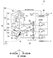
図1は本発明に係る測定ヘッド10の立体図であり、その補助機構の制御ブロック図を重ねて示したものである。測定ヘッド10は、プローブ20と、プローブの駆動装置30と、制御装置40とから構成され、外部の移動装置に保持された状態で、プローブ駆動装置30の動作に伴うプローブ20の動きによってワーク表面を検出する。
The measuring head according to the first embodiment of the present invention will be described with reference to the drawings.
FIG. 1 is a three-dimensional view of the measuring
プローブ駆動装置30は、第1〜第3測定軸系の各スライド機構50〜70と、姿勢検出器80とから成る。第1〜第3測定軸は、互いに平行でない3つの軸からなり、この測定ヘッド10の固有軸である。そのため、例えば鉛直下向きと各測定軸との交角は、測定ヘッド10の姿勢に応じて変化する。以下の説明では、互いに直交する3つの測定軸を使う。
The
第1測定軸系のスライド機構50は、第1スライダ51、第1スライダの案内用ガイド52、及び、スライダ駆動用の第1モータ53と、そのモータ動力の第1補助機構54と、第1測定軸のスケールセンサとを有する。第1スライダ51には第1モータ53によって駆動するボールネジが内蔵されている。第1スライダ51の一方の側面側には案内用ガイド52が設けられている。この案内用ガイド52の前面(第1スライダ51と対向する面)には第1スライダ51用のスライド面が形成されている。これにより、第1スライダ51は案内用ガイド52の前面に沿って第1測定軸方向にスライド可能な構成となっている。また、案内用ガイド52の背面は着脱部になっている。着脱部には、この測定ヘッド10を外部の移動装置に着脱するための治具が形成されている。
The
第2測定軸系のスライド機構60は、第1測定軸に直交する第2測定軸に関するもので、第1測定軸系のスライド機構50の下方に設けられている。スライド機構60は、第2スライダ61、第2スライダの案内用ガイド62、及び、スライダ駆動用の第2モータ63と、そのモータ動力の第2補助機構64と、第2測定軸のスケールセンサとを有する。ここで、第2ガイド62は、第1スライダ51の下面に固定されている。第2ガイド62の下面には第2スライダ61が設けられている。第2スライダ61は、第2ガイド62の下面に沿って第2測定軸方向にスライド可能な構成となっている。
The slide mechanism 60 of the second measurement axis system relates to a second measurement axis orthogonal to the first measurement axis, and is provided below the
第3測定軸系のスライド機構70は、第1および第2測定軸の両方と直交する第3測定軸に関するもので、第2測定軸系のスライド機構60の下方に設けられている。スライド機構70は、第3スライダ71、第3スライダの案内用ガイド(第2スライダ61と一体形成されている)、及び、スライダ駆動用の第3モータ73と、そのモータ動力の第3補助機構74と、第3測定軸のスケールセンサとを有する。第3スライダ71は、第2スライダ61の下面に形成されている第3スライダの案内用ガイドに設けられており、第2スライダ61の下面に沿って第3測定軸方向にスライド可能な構成となっている。
The
以下に、本発明に特徴的なモータ動力の補助機構54〜74について詳しく説明する。
第1補助機構54は、第1エアシリンダ(流体圧シリンダに相当)55、第1自動調圧レギュレータ(流体圧変更手段に相当)57及び第1電磁切換弁(流路切換手段に相当)56を備える。一組の第1エアシリンダ55は、第1測定軸方向に伸縮自在に配置され、第1スライダ51と第1ガイド52を接続する。丁度、第1スライダ51を挟むように2本の第1エアシリンダ55が配置され、ロッド側の先端が第1ガイド52から延設されたアーム部に固定され、反ロッド側の先端が第1スライダ51の側部に固定されている。
The motor-powered
The first
第1ガイド52には、測定ヘッド10の測定姿勢を検知する姿勢検出器80が取り付けられている。姿勢検出器80は、検出信号を制御装置40に送り、そこでヘッドの姿勢が判断される。第1自動調圧レギュレータ57は、制御回路40からの圧力指令値に基づいて、第1エアシリンダ55へ供給するエアー圧力を変更する。第1自動調圧レギュレータ57は、例えばダイヤフラム式の調圧機構を備えたものでもよい。指令値に応じて内蔵の電動機の回転力が変化し、ダイヤフラムへの押力が調整される。特に、チェック弁付きのレギュレータが好ましい。これは、第1エアシリンダ55の付勢方向とは逆方向にスライダ51を移動させる際に、第1自動調圧レギュレータ57の2次側に生じる背圧を逃がして、移動を円滑に行うためである。
A
第1電磁切換弁56は、第1自動調圧レギュレータ57からの圧縮空気の供給先を選ぶことができる。すなわち、第1エアシリンダ55のロッド側の供給口、反ロッド側の供給口のいずれか一方から他方に切り換える流路切換手段として機能する。一例として、3ポート、2ポジションのシングルソレノイド式の電磁切換弁を図1に示す。図1のようにソレノイドを励磁しない場合は、スプリング力でスプールが第1位置を維持し、圧縮空気がシリンダの反ロッド側供給口に送られる。シリンダのロッド側供給口は開放になる。一方、ソレノイドを励磁すれば、スプールが第2位置を維持し、第1自動調圧レギュレータ57からの圧縮空気がシリンダのロッド側供給口に送られる。シリンダの反ロッド側供給口は開放になる。
The first
第1電磁切換弁56は、測定ヘッド10の測定姿勢が変化した際、具体的には対応する測定軸方向が水平方向をまたいで変化する場合に(例えば、測定軸の正の向きが水平方向よりも下向きの状態から上向きに変化した場合など)、エアーの供給先を切り換える。
The first
第2補助機構64は、第2エアシリンダ65、第2電磁切換弁66及び第2自動調圧レギュレータ67を備える。一組の第2エアシリンダ65は、第2測定軸方向に伸縮自在に配置され、第2スライダ61と第2ガイド62を接続する。丁度、第2ガイド62を挟むように2本のエアシリンダ65が配置され、ロッド側の先端が第2スライダ61の上面に固定され、反ロッド側の先端が第2ガイド62の側部に固定されている。
The second
第2自動調圧レギュレータ67は、姿勢検出手段80からの姿勢情報に基づいて、第2エアシリンダ65へ供給するエアー圧力を変更する。第2電磁切換弁66は、第2自動調圧レギュレータ67からのエアーの供給先をエアシリンダのロッド側の供給口および反ロッド側の供給口のいずれか一方から他方に切り換える。
The second automatic
第3補助機構74は、第3エアシリンダ75、第3電磁切換弁76及び第3自動調圧レギュレータ77を備える。一組の第3エアシリンダ75は、第3測定軸方向に伸縮自在に配置され、第3スライダ71と第3ガイド(第2スライダ61)を接続する。丁度、第2スライダ61を挟むように2本のエアシリンダ75が配置され、ロッド側の先端が第2スライダ61の側面に固定され、反ロッド側の先端が第3スライダ71の側部に固定されている。
The third
第3自動調圧レギュレータ77は、第1、第2と同様に第3エアシリンダ75へのエアー圧力を変更する。第3電磁切換弁76は、第3自動調圧レギュレータ77からのエアーの供給先をエアシリンダのロッド側の供給口および反ロッド側の供給口のいずれか一方から他方に切り換える。
The third automatic
プローブ20は、先端に測定子が付いた棒状のスタイラスと、このスタイラスを支持する円筒状の支持部とから成る。スタイラスの支持部は、第3スライダ71に保持されている。
The
測定ヘッド10の制御装置40は、姿勢検出器80からの信号に基づいて、ヘッドの姿勢を判断するとともに、その姿勢に基づいて各自動調圧レギュレータ57,67,77へエアー圧力の指令値を送る。また、ヘッドの姿勢に基づいて電磁切換弁56,66,76へ選択した流路の指令値を送る。この制御装置40は、三次元測定機などの外部の移動装置の制御装置に組み込まれていてもよい。
The
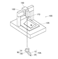
測定ヘッド10の使用例を図2に示す。測定ヘッド10は、CNC三次元座標測定機100のスピンドル170に任意の姿勢で取り付けられている。三次元測定機100は、X軸テーブル120、Y軸及びZ軸スライダ150,160を各々動作させて測定ヘッド10を所望位置へ移動させる。三次元測定機100の各移動軸(X〜Z軸)に設けられたスケールセンサ(測定ヘッド10に内蔵のスケールセンサと区別する)が、テーブル120及びスライダ150,160の位置情報を検出し、三次元測定機100の制御装置に送る。制御装置は、これらの検出値によって測定ヘッド10の位置座標を得る。
An example of using the measuring
次に、測定ヘッド10は、プローブ20を第1〜第3測定軸方向にスライドさせてワーク表面Wを検知させる。ワーク表面を検知した際の測定ヘッド10の各スライダ51,61,71の移動量を各々のスケールセンサが読み取って、三次元測定機100の制御装置に送る。制御装置は、これらの読取値によってワーク表面の位置座標を得る。
Next, the
測定ヘッド10のプローブ駆動装置30だけの動作で、例えば、第1工程でプローブ20をワークWに接近させ、ワーク表面を検出する。そして、プローブ20を離間させた後、第2工程でプローブ20を次の測定位置に移動させる。その後、第1工程と同様にワーク表面を検出する。このような工程により、三次元測定機100のスピンドル170に保持された測定ヘッド10の位置や姿勢を変えずに、測定ヘッド10によるプローブ20の移動だけでワーク表面の座標測定ができる。
With the operation of only the
測定ヘッド10の測定姿勢は、姿勢検出器80の検出信号に基づいて制御装置40が判断する。制御手段40は、測定姿勢に応じた各自動調圧レギュレータ57〜77の圧力指令値を表データなどから読み出して、指令値をレギュレータに送る。制御装置40からの圧力指令値を受けて、各自動調圧レギュレータ57〜77は、内蔵された電動機の回転力を変化させて、接続するエアシリンダへの供給圧力を個別に調整する。また、制御装置40は、測定姿勢に応じて圧縮空気の流路を選択し、その流路への切換指令値を電磁切換弁56〜76に送る。
The measurement posture of the
第1エアシリンダ55は、第1自動調圧レギュレータ57が調整したエアー圧力で第1スライダ51を付勢する。つまり、第1スライダ51を押すか、引くかである。各測定軸に対するエアー圧力の指令値は、各エアシリンダ55〜75の付勢力が各スライダ51〜71に作用する重力の測定軸方向の分力に相当する大きさになるように、設定されている。
The
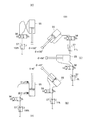
制御装置40には、例えば、図3に示す関係に設定された測定姿勢とエアー圧力の表データが記憶されている。ここでは、鉛直下向きに対する第1〜第3測定軸の傾斜角θ1〜θ3を用いて測定姿勢を表す。説明上、各測定軸の正の向きを、エアシリンダのロッド側から反ロッド側を見る方向に定める(図1中の座標軸を参照)。
For example, the
第1測定軸の第1エアシリンダ55に着目して説明する。
傾斜角θ1=0°(第1測定軸:鉛直下向き)の場合、エアー圧力を最大(100%)とし、供給先を反ロッド側とする。図3(A)参照。
θ=45°では、エアー圧力を71%とし、供給先を反ロッド側とする。図3(B)参照。
θ=90°(水平)の場合、エアー圧力を最小(0%)とする。供給先はどちらでもよいが、ここでは、直前の状態(例えば反ロッド側)を維持するものとする。図3(C)参照。
θ=135°では、エアー圧力を71%とし、供給先をロッド側とする。図3(D)参照。
θ=180°(鉛直上向き)の場合、エアー圧力を最大(100%)とし、供給先をロッド側とする。図3(E)参照。
The description will be given focusing on the
When the inclination angle θ1 = 0 ° (first measurement axis: vertically downward), the air pressure is maximized (100%) and the supply destination is the opposite rod side. See FIG. 3 (A).
At θ = 45 °, the air pressure is 71% and the supply destination is the opposite rod side. See FIG. 3 (B).
When θ = 90 ° (horizontal), the air pressure is set to the minimum (0%). The supply destination may be either, but here, it is assumed that the immediately preceding state (for example, the anti-rod side) is maintained. See FIG. 3 (C).
At θ = 135 °, the air pressure is 71% and the supply destination is the rod side. See FIG. 3 (D).
When θ = 180 ° (vertically upward), the air pressure is maximized (100%) and the supply destination is the rod side. See FIG. 3 (E).
なお、第1電磁切換弁56は、第1測定軸方向がどのように変化するか対応して、例えば次のように動作する。図3(C)のように第1測定軸が水平(θ=90°)になった場合は、その直前の傾き状態における流路を維持する。さらに第1測定軸が水平状態を超えて、逆方向に傾いた場合(θ<90°の傾斜からθ>90°の傾斜に変化した場合。又は、これとは逆に、θ>90°の傾斜からθ<90°の傾斜に変化した場合)は、エアーの供給先、つまり、流路を切り換える。
The first
本実施形態の測定ヘッド10による効果について説明する。
(1)測定姿勢に応じて各スライダ51〜71に作用する重力の影響は大きく変化するが、測定ヘッド10の構成であれば、測定姿勢に応じて各エアシリンダ55〜75の付勢力を変更し、各スライダ51〜71に対して個別に調整した付勢力を加えるようにしたので、姿勢変化に伴う各モータ53〜73の負荷変動をゼロ若しくは非常に小さく抑えることができる。これにより、測定姿勢に依存しないモータの駆動性能が発揮され、測定ヘッドの性能・機能を損なわずに、あらゆる測定姿勢をとり得る測定ヘッド10を提供できる。
(2)図2のような門型のCNC三次元座標測定機100に測定ヘッドを適用するといった測定ヘッドの用途を拡大させることができる。
(3)三次元測定機100のスピンドル170への測定ヘッド10の取り付け姿勢の自由度が上がる。
(4)測定ヘッド10に追加する機械要素を実質的にエアシリンダ55〜75だけとすることができる。図7のバネを利用した場合とほとんど構造の変化がなくて済み、小型の測定ヘッドを維持し易い。
The effect of the measuring
(1) The influence of gravity acting on each
(2) It is possible to expand the use of the measuring head, such as applying the measuring head to the gate-shaped CNC three-dimensional coordinate measuring
(3) The degree of freedom in the mounting posture of the measuring
(4) The mechanical element added to the measuring
なお、図4に本実施形態に係る測定ヘッドの変形例を示す。すなわち、上記の測定ヘッド10の構成にさらに姿勢変更手段90を設けることで、測定ヘッド10Aに自己姿勢変更機能を付与することができる。図4の姿勢変更手段90は、一例に過ぎないが、三次元測定機100のスピンドル170に着脱自在なベース部91と、このベース部91に保持された球状部92とを有する。球状部92は、ベース部91に対して姿勢を任意に変えられるように支持されている。このような球状部92に測定ヘッド10Aの第1ガイド52を固定すればよい。つまり、スピンドル170に対するベース部91の取付姿勢を変えなくても、取付け後に、プローブ20の向きを姿勢変更手段90の可動範囲内で自由に変更することができる。
Note that FIG. 4 shows a modified example of the measuring head according to the present embodiment. That is, by further providing the posture changing means 90 in the configuration of the measuring
この変形例では、姿勢変更手段90が、三次元測定機100のスピンドル170と測定ヘッド10の第1ガイド52の間に設けた。一方、図4の姿勢変更手段90を、図1に示した測定ヘッド10の第3スライダ71とプローブ20の間に設ける場合もある。しかし、こうすると姿勢変更手段90の自重が各スライダ51〜71に作用してしまう。つまり、測定ヘッド10の末端質量が増加することになり、測定ヘッド10の固有振動数の低下や、測定の高速化の障害になり易い。従って、前述の変形例の測定ヘッド10Aの方が優れている。
In this modification, the
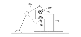
次に、本発明の第二実施形態に係る多関節型の三次元測定機について図面に基づいて説明する。図5は前述の実施形態の測定ヘッド10を、ロボットアーム200のような多関節型の移動装置に適用した三次元測定機を示す。ロボットアーム200によって測定ヘッド10を所望の位置および姿勢に保持することができるので、例えば、ベルトコンベヤで運搬される大型の製品や部品を、その状態のままオンラインで測定できる。
Next, the articulated coordinate measuring machine according to the second embodiment of the present invention will be described with reference to the drawings. FIG. 5 shows a coordinate measuring machine in which the measuring
図6に基づいて、この多関節型の三次元測定機による測定方法の一例を説明する。
ロボットアーム200が、図示しない交換ラックに掛けられている測定ヘッド10を取りにいく。
次に、測定ヘッド10は、ロボットアーム200先端の保持部210に保持された状態で、ベルトコンベヤ上の加工部品Wの測定箇所へ持っていかれ、所望の姿勢に維持される。
次に、前述の姿勢検出器80(図1)によって測定ヘッド10の姿勢を検出し、その姿勢に応じて各測定軸のエアシリンダ55〜75への供給エアーの流路を決定し、エアー圧力を調整する。
次に、測定ヘッド10を単独で動作させて、プローブ20により測定箇所の表面性状を測定する。
測定後は、測定ヘッド10を保持したまま次の測定指令を待ってもよいし、測定ヘッド10をラックに戻して他の測定や加工などの作業に進んでもよい。
An example of the measurement method by the articulated coordinate measuring machine will be described with reference to FIG.
The
Next, the
Next, the posture of the measuring
Next, the measuring
After the measurement, the
このように多関節型の三次元測定機への測定ヘッド10の適用といった用途が可能になった。すなわち、測定ヘッド10にエアシリンダ55〜75を利用したモータ動力の補助機構54〜74を設けたので、どのような測定姿勢でも測定ヘッド10のモータ駆動が安定する。従って、本実施形態のような複雑な動きをするロボットアーム200に測定ヘッド10を取り付ける場合であっても、測定ヘッド10のプローブ駆動機構30が測定姿勢の違いに基づく重力の影響を受けにくく、測定ヘッド10の安定測定が実現した。
In this way, applications such as application of the measuring
10,10A 測定ヘッド
20 プローブ
30 プローブ駆動装置
40 制御装置
50,60,70 第1〜第3スライド機構
51,61,71 第1〜第3スライダ
52,62 第1,第2ガイド
53,63,73 第1〜第3モータ
54,64,74 第1〜第3補助機構
55,65,75 第1〜第3エアシリンダ(第1〜第3流体圧シリンダ)
56,66,76 第1〜第3電磁切換弁(第1〜第3流路切換手段)
57,67,77 第1〜第3自動調圧レギュレータ(第1〜第3流体圧変更手段)
80 姿勢検出器(姿勢検出手段)
100 門型の三次元測定機(移動装置)
200 ロボットアーム(移動装置)
10,
56, 66, 76 1st to 3rd electromagnetic switching valves (1st to 3rd flow path switching means)
57, 67, 77 1st to 3rd automatic pressure regulation regulators (1st to 3rd fluid pressure changing means)
80 Posture detector (posture detection means)
100-gate type 3D measuring machine (mobile device)
200 Robot arm (moving device)
Claims (3)
前記第1測定軸と平行でない第2測定軸用の第2スライダ、前記第1スライダに固定された案内用の第2ガイド、及び、駆動用の第2モータと、
前記第2スライダに保持されたワーク検知用のプローブと、
を備え、前記各スライダの移動に伴って前記プローブにワーク表面を検出させる測定ヘッドであって、
該測定ヘッドは、外部の任意の移動装置に前記第1ガイドを介して着脱可能であり、
前記第1スライダと前記第1ガイドを接続し前記第1測定軸方向に伸縮自在の第1流体圧シリンダと、
前記第2スライダと前記第2ガイドを接続し前記第2測定軸方向に伸縮自在の第2流体圧シリンダと、
該測定ヘッドの測定姿勢に応じて、前記第1流体圧シリンダ及び前記第2流体圧シリンダへ供給する流体の圧力を変更する第1流体圧変更手段および第2流体圧変更手段と、
を備えることを特徴とする測定ヘッド。 A first slider for the first measurement axis, a first guide for guidance, and a first motor for driving,
A second slider for the second measurement axis that is not parallel to the first measurement axis, a second guide for guidance fixed to the first slider, and a second motor for driving.
The work detection probe held by the second slider and
A measurement head that causes the probe to detect the work surface as the slider moves.
The measuring head can be attached to and detached from any external moving device via the first guide.
A first fluid pressure cylinder that connects the first slider and the first guide and expands and contracts in the first measurement axis direction.
A second fluid pressure cylinder that connects the second slider and the second guide and expands and contracts in the second measurement axis direction.
A first fluid pressure changing means and a second fluid pressure changing means for changing the pressure of the fluid supplied to the first fluid pressure cylinder and the second fluid pressure cylinder according to the measurement posture of the measuring head.
A measuring head characterized by being provided with.
前記各流体圧変更手段は、前記姿勢検出手段からの姿勢情報に基づいて前記流体の圧力を変更することを特徴とする測定ヘッド。 The measuring head according to claim 1 further includes a posture detecting means for detecting the measuring posture of the measuring head.
Each of the fluid pressure changing means is a measuring head that changes the pressure of the fluid based on the posture information from the posture detecting means.
前記第2スライダと前記プローブの間に、前記第1測定軸および前記第2測定軸のいずれとも平行でない第3測定軸用の第3スライダと、前記第2スライダに固定された案内用の第3ガイドと、駆動用の第3モータとが設けられ、
前記プローブは、前記第3ガイドおよび前記第3スライダを介在して、前記第2スライダに保持され、
該測定ヘッドは、さらに、前記第3スライダと前記第3ガイドを接続し前記第3測定軸方向に伸縮自在の第3流体圧シリンダと、
該測定ヘッドの測定姿勢に応じて、前記第3流体圧シリンダへ供給する流体の圧力を変更する第3流体圧変更手段と、を備えることを特徴とする測定ヘッド。 In the measuring head according to claim 1 or 2.
Between the second slider and the probe, a third slider for the third measurement axis that is not parallel to either the first measurement axis or the second measurement axis, and a guide ath fixed to the second slider. A 3 guide and a 3rd motor for driving are provided.
The probe is held by the second slider via the third guide and the third slider.
The measuring head further includes a third fluid pressure cylinder that connects the third slider and the third guide and is expandable and contractible in the third measuring axis direction.
A measuring head comprising: a third fluid pressure changing means for changing the pressure of a fluid supplied to the third fluid pressure cylinder according to the measuring posture of the measuring head.
Priority Applications (4)
| Application Number | Priority Date | Filing Date | Title |
|---|---|---|---|
| JP2017061952A JP6830386B2 (en) | 2017-03-27 | 2017-03-27 | Measuring head |
| US15/933,840 US10551184B2 (en) | 2017-03-27 | 2018-03-23 | Measuring head |
| DE102018204654.9A DE102018204654A1 (en) | 2017-03-27 | 2018-03-27 | probe |
| CN201810259347.6A CN108662996B (en) | 2017-03-27 | 2018-03-27 | Measuring head |
Applications Claiming Priority (1)
| Application Number | Priority Date | Filing Date | Title |
|---|---|---|---|
| JP2017061952A JP6830386B2 (en) | 2017-03-27 | 2017-03-27 | Measuring head |
Publications (2)
| Publication Number | Publication Date |
|---|---|
| JP2018163125A JP2018163125A (en) | 2018-10-18 |
| JP6830386B2 true JP6830386B2 (en) | 2021-02-17 |
Family
ID=63450657
Family Applications (1)
| Application Number | Title | Priority Date | Filing Date |
|---|---|---|---|
| JP2017061952A Expired - Fee Related JP6830386B2 (en) | 2017-03-27 | 2017-03-27 | Measuring head |
Country Status (4)
| Country | Link |
|---|---|
| US (1) | US10551184B2 (en) |
| JP (1) | JP6830386B2 (en) |
| CN (1) | CN108662996B (en) |
| DE (1) | DE102018204654A1 (en) |
Families Citing this family (5)
| Publication number | Priority date | Publication date | Assignee | Title |
|---|---|---|---|---|
| JP6830386B2 (en) * | 2017-03-27 | 2021-02-17 | 株式会社ミツトヨ | Measuring head |
| CN110243323B (en) * | 2019-06-18 | 2024-10-29 | 苏州博达特机电科技有限公司 | Online measuring device for Luban lock |
| CN111679137A (en) * | 2020-05-26 | 2020-09-18 | 江西源盛泰电子科技有限公司 | Backlight screen detection tool |
| JP2022037326A (en) * | 2020-08-25 | 2022-03-09 | 株式会社オプティム | Programs, methods, and systems |
| CN116678741B (en) * | 2023-05-31 | 2023-10-27 | 涿州市紫阳机械设备科技有限公司 | Mechanical part machining equipment with detection function |
Family Cites Families (19)
| Publication number | Priority date | Publication date | Assignee | Title |
|---|---|---|---|---|
| US4389781A (en) * | 1981-08-10 | 1983-06-28 | The Bendix Corporation | Pneumatic counterbalance for a coordinate measuring machine |
| DE4424225A1 (en) * | 1994-07-09 | 1996-01-11 | Zeiss Carl Fa | Probe for coordinate measuring machines |
| DE10100350A1 (en) * | 2001-01-05 | 2002-07-11 | Zeiss Carl | Probe for a coordinate measuring machine |
| JP4330388B2 (en) * | 2003-07-28 | 2009-09-16 | 株式会社ミツトヨ | Copy probe |
| US7395607B1 (en) * | 2005-06-14 | 2008-07-08 | Discovery Technology International, Lllp | Rotational and translational microposition apparatus and method |
| JP5728769B2 (en) * | 2006-11-20 | 2015-06-03 | ヘキサゴン メトロロジー アクチボラゲット | Coordinate measuring machine with improved fitting |
| JP5371532B2 (en) | 2009-04-23 | 2013-12-18 | 株式会社ミツトヨ | CMM |
| JP5451180B2 (en) * | 2009-05-22 | 2014-03-26 | 株式会社ミツトヨ | Roundness measuring machine |
| JP2011135751A (en) * | 2009-12-25 | 2011-07-07 | Nikon Corp | Drive device and measuring device |
| US8432119B2 (en) * | 2010-04-14 | 2013-04-30 | Babcock & Wilcox Technical Services Y-12, Llc | Method and apparatus for characterizing and enhancing the functional performance of machine tools |
| JP6010045B2 (en) * | 2011-01-19 | 2016-10-19 | レニショウ パブリック リミテッド カンパニーRenishaw Public Limited Company | Analog measuring probe and operating method for machine tool apparatus |
| CN201983771U (en) * | 2011-03-22 | 2011-09-21 | 青岛麦科三维测量设备有限公司 | Air-balanced device and three-coordinate measuring machine |
| JP6611168B2 (en) * | 2015-04-07 | 2019-11-27 | 株式会社ミツトヨ | Probe measuring force adjustment device |
| JP6649013B2 (en) * | 2015-08-27 | 2020-02-19 | 株式会社ミツトヨ | Probe head rotation mechanism |
| JP6584892B2 (en) | 2015-09-24 | 2019-10-02 | ジヤトコ株式会社 | Vehicle sailing stop control method and control apparatus |
| JP6769764B2 (en) * | 2016-07-19 | 2020-10-14 | 株式会社ミツトヨ | Measuring probe and measuring device |
| DE102017100992A1 (en) * | 2017-01-19 | 2018-07-19 | Carl Mahr Holding Gmbh | Measuring device and method for operating a measuring device |
| JP2018151187A (en) * | 2017-03-10 | 2018-09-27 | 株式会社島津製作所 | Scanning probe microscope |
| JP6830386B2 (en) * | 2017-03-27 | 2021-02-17 | 株式会社ミツトヨ | Measuring head |
-
2017
- 2017-03-27 JP JP2017061952A patent/JP6830386B2/en not_active Expired - Fee Related
-
2018
- 2018-03-23 US US15/933,840 patent/US10551184B2/en not_active Expired - Fee Related
- 2018-03-27 CN CN201810259347.6A patent/CN108662996B/en not_active Expired - Fee Related
- 2018-03-27 DE DE102018204654.9A patent/DE102018204654A1/en not_active Withdrawn
Also Published As
| Publication number | Publication date |
|---|---|
| US20180274914A1 (en) | 2018-09-27 |
| JP2018163125A (en) | 2018-10-18 |
| CN108662996B (en) | 2021-09-10 |
| US10551184B2 (en) | 2020-02-04 |
| DE102018204654A1 (en) | 2018-09-27 |
| CN108662996A (en) | 2018-10-16 |
Similar Documents
| Publication | Publication Date | Title |
|---|---|---|
| JP6830386B2 (en) | Measuring head | |
| US7076883B2 (en) | Scanning probe | |
| JP4875180B2 (en) | Contact-type measuring device with fine contact force adjustment mechanism | |
| CA2807204C (en) | Device for error correction for cnc machines | |
| US10107618B2 (en) | Coordinate measuring machine | |
| CN102564368B (en) | Coordinates measuring head unit and coordinates measuring machine | |
| CN105716559A (en) | Coordinate measuring machine, probing system, and method of compensating forces at probe elements | |
| US20160084631A1 (en) | Roundness measurement device and control method | |
| JP5444590B2 (en) | Workpiece reference point on-machine detection method and machining apparatus using the method | |
| US10422629B2 (en) | Method and apparatus for determining a plurality of spatial coordinates on a measurement object | |
| JP5355037B2 (en) | Accuracy measuring method, error control method for numerically controlled machine tool, and numerically controlled machine tool having error correcting function | |
| EP2141445B1 (en) | Measuring instrument | |
| JP6800421B1 (en) | Measuring device and measuring method | |
| JP2025036506A (en) | Shape measuring device | |
| JP2020517939A (en) | Measuring device counter balance | |
| US20070180962A1 (en) | Control method for a machine tool with numerical control | |
| JP7637329B2 (en) | Shape measuring device | |
| JP2010201581A (en) | Workpiece attitude control device of machine tool | |
| JP4762194B2 (en) | Processing apparatus and processing method | |
| JP2005081444A (en) | Device and method for measuring accuracy of driving device, program for measuring accuracy of driving device, recording medium recording the program, and method for calibrating driving device | |
| CN109397090A (en) | Measuring device | |
| JP2005249710A (en) | Shape-measuring machine | |
| KR101369857B1 (en) | Portable 3 dimensional measurements apparatus | |
| JP2002154028A (en) | Moving stage mechanism of processing equipment | |
| KR101307195B1 (en) | Portable 3 dimensional measurements apparatus |
Legal Events
| Date | Code | Title | Description |
|---|---|---|---|
| A621 | Written request for application examination |
Free format text: JAPANESE INTERMEDIATE CODE: A621 Effective date: 20200213 |
|
| A977 | Report on retrieval |
Free format text: JAPANESE INTERMEDIATE CODE: A971007 Effective date: 20201217 |
|
| TRDD | Decision of grant or rejection written | ||
| A01 | Written decision to grant a patent or to grant a registration (utility model) |
Free format text: JAPANESE INTERMEDIATE CODE: A01 Effective date: 20210105 |
|
| A61 | First payment of annual fees (during grant procedure) |
Free format text: JAPANESE INTERMEDIATE CODE: A61 Effective date: 20210126 |
|
| R150 | Certificate of patent or registration of utility model |
Ref document number: 6830386 Country of ref document: JP Free format text: JAPANESE INTERMEDIATE CODE: R150 |
|
| LAPS | Cancellation because of no payment of annual fees |