JP6830353B2 - Sphygmomanometer and blood pressure measurement method and equipment - Google Patents
Sphygmomanometer and blood pressure measurement method and equipment Download PDFInfo
- Publication number
- JP6830353B2 JP6830353B2 JP2016256028A JP2016256028A JP6830353B2 JP 6830353 B2 JP6830353 B2 JP 6830353B2 JP 2016256028 A JP2016256028 A JP 2016256028A JP 2016256028 A JP2016256028 A JP 2016256028A JP 6830353 B2 JP6830353 B2 JP 6830353B2
- Authority
- JP
- Japan
- Prior art keywords
- cuff
- blood pressure
- sensing cuff
- back plate
- sphygmomanometer
- Prior art date
- Legal status (The legal status is an assumption and is not a legal conclusion. Google has not performed a legal analysis and makes no representation as to the accuracy of the status listed.)
- Active
Links
- 238000009530 blood pressure measurement Methods 0.000 title claims description 45
- 238000000034 method Methods 0.000 title claims description 25
- 238000003825 pressing Methods 0.000 claims description 133
- 230000036772 blood pressure Effects 0.000 claims description 108
- 239000012530 fluid Substances 0.000 claims description 74
- 238000005259 measurement Methods 0.000 claims description 62
- 230000002093 peripheral effect Effects 0.000 claims description 52
- 230000005540 biological transmission Effects 0.000 claims description 23
- 238000004364 calculation method Methods 0.000 claims description 12
- 230000004308 accommodation Effects 0.000 claims description 6
- 238000003860 storage Methods 0.000 claims description 3
- 210000000707 wrist Anatomy 0.000 description 91
- 210000004204 blood vessel Anatomy 0.000 description 25
- XLYOFNOQVPJJNP-UHFFFAOYSA-N water Substances O XLYOFNOQVPJJNP-UHFFFAOYSA-N 0.000 description 20
- 238000010586 diagram Methods 0.000 description 17
- 238000009826 distribution Methods 0.000 description 16
- 210000002321 radial artery Anatomy 0.000 description 10
- 238000004088 simulation Methods 0.000 description 9
- 230000006870 function Effects 0.000 description 8
- 230000001133 acceleration Effects 0.000 description 7
- 210000002435 tendon Anatomy 0.000 description 7
- 210000001367 artery Anatomy 0.000 description 6
- 238000004891 communication Methods 0.000 description 6
- 230000000694 effects Effects 0.000 description 6
- 210000002559 ulnar artery Anatomy 0.000 description 6
- 238000001514 detection method Methods 0.000 description 5
- 239000000463 material Substances 0.000 description 5
- 238000012423 maintenance Methods 0.000 description 4
- 230000006835 compression Effects 0.000 description 3
- 238000007906 compression Methods 0.000 description 3
- 238000005401 electroluminescence Methods 0.000 description 3
- 239000011347 resin Substances 0.000 description 3
- 229920005989 resin Polymers 0.000 description 3
- 125000006850 spacer group Chemical group 0.000 description 3
- 230000035488 systolic blood pressure Effects 0.000 description 3
- 238000012546 transfer Methods 0.000 description 3
- PEDCQBHIVMGVHV-UHFFFAOYSA-N Glycerine Chemical compound OCC(O)CO PEDCQBHIVMGVHV-UHFFFAOYSA-N 0.000 description 2
- 239000004743 Polypropylene Substances 0.000 description 2
- 239000011521 glass Substances 0.000 description 2
- 239000007788 liquid Substances 0.000 description 2
- 210000003141 lower extremity Anatomy 0.000 description 2
- 238000004519 manufacturing process Methods 0.000 description 2
- 239000004033 plastic Substances 0.000 description 2
- 229920003023 plastic Polymers 0.000 description 2
- -1 polypropylene Polymers 0.000 description 2
- 229920001155 polypropylene Polymers 0.000 description 2
- 229920002635 polyurethane Polymers 0.000 description 2
- 239000004814 polyurethane Substances 0.000 description 2
- 238000012545 processing Methods 0.000 description 2
- 230000003014 reinforcing effect Effects 0.000 description 2
- 210000000623 ulna Anatomy 0.000 description 2
- 238000012795 verification Methods 0.000 description 2
- 238000003466 welding Methods 0.000 description 2
- 206010040007 Sense of oppression Diseases 0.000 description 1
- 210000003423 ankle Anatomy 0.000 description 1
- 238000004422 calculation algorithm Methods 0.000 description 1
- 230000035487 diastolic blood pressure Effects 0.000 description 1
- 229920001971 elastomer Polymers 0.000 description 1
- 239000000806 elastomer Substances 0.000 description 1
- 238000002474 experimental method Methods 0.000 description 1
- 230000001771 impaired effect Effects 0.000 description 1
- 238000007689 inspection Methods 0.000 description 1
- 239000010985 leather Substances 0.000 description 1
- 239000007769 metal material Substances 0.000 description 1
- 238000012986 modification Methods 0.000 description 1
- 230000004048 modification Effects 0.000 description 1
- 238000012544 monitoring process Methods 0.000 description 1
- 238000000465 moulding Methods 0.000 description 1
- 230000004044 response Effects 0.000 description 1
- 210000001364 upper extremity Anatomy 0.000 description 1
- 210000000689 upper leg Anatomy 0.000 description 1
Images


Classifications
-
- A—HUMAN NECESSITIES
- A61—MEDICAL OR VETERINARY SCIENCE; HYGIENE
- A61B—DIAGNOSIS; SURGERY; IDENTIFICATION
- A61B5/00—Measuring for diagnostic purposes; Identification of persons
- A61B5/02—Detecting, measuring or recording pulse, heart rate, blood pressure or blood flow; Combined pulse/heart-rate/blood pressure determination; Evaluating a cardiovascular condition not otherwise provided for, e.g. using combinations of techniques provided for in this group with electrocardiography or electroauscultation; Heart catheters for measuring blood pressure
- A61B5/021—Measuring pressure in heart or blood vessels
- A61B5/022—Measuring pressure in heart or blood vessels by applying pressure to close blood vessels, e.g. against the skin; Ophthalmodynamometers
- A61B5/02233—Occluders specially adapted therefor
-
- A—HUMAN NECESSITIES
- A61—MEDICAL OR VETERINARY SCIENCE; HYGIENE
- A61B—DIAGNOSIS; SURGERY; IDENTIFICATION
- A61B5/00—Measuring for diagnostic purposes; Identification of persons
- A61B5/02—Detecting, measuring or recording pulse, heart rate, blood pressure or blood flow; Combined pulse/heart-rate/blood pressure determination; Evaluating a cardiovascular condition not otherwise provided for, e.g. using combinations of techniques provided for in this group with electrocardiography or electroauscultation; Heart catheters for measuring blood pressure
- A61B5/021—Measuring pressure in heart or blood vessels
- A61B5/022—Measuring pressure in heart or blood vessels by applying pressure to close blood vessels, e.g. against the skin; Ophthalmodynamometers
-
- A—HUMAN NECESSITIES
- A61—MEDICAL OR VETERINARY SCIENCE; HYGIENE
- A61B—DIAGNOSIS; SURGERY; IDENTIFICATION
- A61B5/00—Measuring for diagnostic purposes; Identification of persons
- A61B5/68—Arrangements of detecting, measuring or recording means, e.g. sensors, in relation to patient
- A61B5/6801—Arrangements of detecting, measuring or recording means, e.g. sensors, in relation to patient specially adapted to be attached to or worn on the body surface
- A61B5/6802—Sensor mounted on worn items
- A61B5/681—Wristwatch-type devices
-
- A—HUMAN NECESSITIES
- A61—MEDICAL OR VETERINARY SCIENCE; HYGIENE
- A61B—DIAGNOSIS; SURGERY; IDENTIFICATION
- A61B5/00—Measuring for diagnostic purposes; Identification of persons
- A61B5/68—Arrangements of detecting, measuring or recording means, e.g. sensors, in relation to patient
- A61B5/6801—Arrangements of detecting, measuring or recording means, e.g. sensors, in relation to patient specially adapted to be attached to or worn on the body surface
- A61B5/6843—Monitoring or controlling sensor contact pressure
-
- A—HUMAN NECESSITIES
- A61—MEDICAL OR VETERINARY SCIENCE; HYGIENE
- A61B—DIAGNOSIS; SURGERY; IDENTIFICATION
- A61B2562/00—Details of sensors; Constructional details of sensor housings or probes; Accessories for sensors
- A61B2562/02—Details of sensors specially adapted for in-vivo measurements
- A61B2562/0219—Inertial sensors, e.g. accelerometers, gyroscopes, tilt switches
-
- A—HUMAN NECESSITIES
- A61—MEDICAL OR VETERINARY SCIENCE; HYGIENE
- A61B—DIAGNOSIS; SURGERY; IDENTIFICATION
- A61B5/00—Measuring for diagnostic purposes; Identification of persons
- A61B5/02—Detecting, measuring or recording pulse, heart rate, blood pressure or blood flow; Combined pulse/heart-rate/blood pressure determination; Evaluating a cardiovascular condition not otherwise provided for, e.g. using combinations of techniques provided for in this group with electrocardiography or electroauscultation; Heart catheters for measuring blood pressure
- A61B5/021—Measuring pressure in heart or blood vessels
- A61B5/02141—Details of apparatus construction, e.g. pump units or housings therefor, cuff pressurising systems, arrangements of fluid conduits or circuits
Landscapes
- Health & Medical Sciences (AREA)
- Life Sciences & Earth Sciences (AREA)
- Surgery (AREA)
- Animal Behavior & Ethology (AREA)
- Pathology (AREA)
- Engineering & Computer Science (AREA)
- Biomedical Technology (AREA)
- Heart & Thoracic Surgery (AREA)
- Medical Informatics (AREA)
- Molecular Biology (AREA)
- Physics & Mathematics (AREA)
- Biophysics (AREA)
- General Health & Medical Sciences (AREA)
- Public Health (AREA)
- Veterinary Medicine (AREA)
- Vascular Medicine (AREA)
- Cardiology (AREA)
- Ophthalmology & Optometry (AREA)
- Physiology (AREA)
- Dentistry (AREA)
- Measuring Pulse, Heart Rate, Blood Pressure Or Blood Flow (AREA)
Description
この発明は血圧計に関し、より詳しくは、被測定部位を取り巻いて装着されるベルトと、ポンプを搭載した本体とを備えた血圧計に関する。また、この発明は、被測定部位の血圧を測定する血圧測定方法に関する。さらに、この発明は、血圧測定機能を備えた機器に関する。 The present invention relates to a sphygmomanometer, and more particularly to a sphygmomanometer including a belt worn around a site to be measured and a main body equipped with a pump. The present invention also relates to a blood pressure measuring method for measuring the blood pressure of a measurement site. Furthermore, the present invention relates to a device having a blood pressure measuring function.
従来、この種の血圧計としては、例えば特許文献1(特開平11−309119号公報)に開示されているように、被測定部位としての手首に巻き付けられるカフと、このカフに一体に取り付けられた本体とを有するものが知られている。この血圧計では、帯状のベルト内に、動脈を圧迫する袋状の血圧測定用カフと、この血圧測定用カフの外側に設けた介在部材と、この介在部材の外側に設けられた袋状の押圧カフとを備え、血圧測定用カフ内の圧力を、本体に搭載された圧力センサで検出する構成になっている。血圧測定時には、上記ベルトが手首を取り巻いて装着された状態で、本体に搭載されたポンプから上記血圧測定用カフへ加圧用の所定量の空気を供給し、その後、押圧カフにも空気を供給して、手首の動脈(橈骨動脈、尺骨動脈)を圧迫する。そして、上記圧力センサの出力に基づいて、オシロメトリック法により血圧測定値が求められる。この血圧計においては、血圧測定用カフに所定量の空気を供給し、生体部位を十分に圧迫する力は介在部材と押圧カフとにより得ることで、カフ装着時の圧迫感や不快感等を解消している。 Conventionally, as this type of sphygmomanometer, for example, as disclosed in Patent Document 1 (Japanese Unexamined Patent Publication No. 11-309119), a cuff wrapped around a wrist as a measurement site and an integral attachment to the cuff. It is known to have a main body. In this sphygmomanometer, a bag-shaped blood pressure measuring cuff that presses an artery in a band-shaped belt, an intervening member provided outside the blood pressure measuring cuff, and a bag-shaped intervening member provided outside the intervening member. It is equipped with a pressing cuff and is configured to detect the pressure inside the blood pressure measuring cuff with a pressure sensor mounted on the main body. At the time of blood pressure measurement, a predetermined amount of air for pressurization is supplied from the pump mounted on the main body to the blood pressure measurement cuff while the belt is worn around the wrist, and then air is also supplied to the pressing cuff. Then, the wrist arteries (radial artery, ulnar artery) are compressed. Then, based on the output of the pressure sensor, the blood pressure measurement value is obtained by the oscillometric method. In this sphygmomanometer, a predetermined amount of air is supplied to the blood pressure measuring cuff, and a force that sufficiently presses the living body part is obtained by the intervening member and the pressing cuff, thereby giving a feeling of oppression and discomfort when the cuff is attached. It has been resolved.
ところで、最近の健康志向ブームから、血圧計(血圧測定用カフ)を手首に常時装着した状態で、血圧を測定したいとのニーズが高まっている。その場合、見栄え、装着の快適さ等の観点から、カフの幅方向寸法(手首の長手方向に沿った方向の寸法)をできるだけ小さくすることが望まれる。 By the way, due to the recent health-conscious boom, there is an increasing need to measure blood pressure with a sphygmomanometer (cuff for measuring blood pressure) always worn on the wrist. In that case, it is desired to make the width direction dimension of the cuff (the dimension in the direction along the longitudinal direction of the wrist) as small as possible from the viewpoint of appearance, wearing comfort, and the like.
カフの幅方向寸法を例えば25mm程度に小さく設定した場合、血圧測定精度の観点から、カフの幅方向に関して被測定部位(手首)に対する押圧力を均一にすることが重要になる。ここで、本発明者は、実験により、板状の介在部材における上記幅方向の縁部に対応する上記被測定部位の位置では、応力集中が発生して押圧力が高くなるということを発見した。したがって、仮に介在部材と血圧測定用カフの上記幅方向の寸法が等しい場合には、この血圧測定用カフに対する押圧力は、上記応力集中によって、被測定部位の皮膚表面位置と血管位置とにおいてずれが生じ、上記幅方向の中央部よりも縁部の方が高くなる。その結果、上記被測定部位に対する血圧測定用カフの押圧力は、上記幅方向において均一なものとはならず、血圧値の測定誤差が発生するという問題がある。 When the width direction dimension of the cuff is set as small as, for example, about 25 mm, it is important to make the pressing force on the measurement site (wrist) uniform in the width direction of the cuff from the viewpoint of blood pressure measurement accuracy. Here, the present inventor has discovered through experiments that stress concentration occurs and the pressing force increases at the position of the portion to be measured corresponding to the edge portion in the width direction of the plate-shaped intervening member. .. Therefore, if the intervening member and the blood pressure measuring cuff have the same dimensions in the width direction, the pressing force on the blood pressure measuring cuff shifts between the skin surface position and the blood pressure position of the measurement site due to the stress concentration. Is generated, and the edge portion is higher than the central portion in the width direction. As a result, the pressing force of the blood pressure measuring cuff with respect to the measured portion is not uniform in the width direction, and there is a problem that a measurement error of the blood pressure value occurs.
そこで、この発明の課題は、介在部材を介して血圧測定用カフの押圧を行って血圧を測定する場合でも、血圧を精度良く測定できる血圧計および血圧測定方法並びに機器を提供することにある。 Therefore, an object of the present invention is to provide a sphygmomanometer, a blood pressure measuring method, and an apparatus capable of accurately measuring blood pressure even when the blood pressure is measured by pressing a blood pressure measuring cuff through an intervening member.
上記課題を解決するため、この発明の血圧計は、
被測定部位を取り巻いて装着されるべき袋状のセンシングカフと、
上記センシングカフに対して、上記被測定部位とは反対側の面に沿って配置された背板と、
上記背板を上記被測定部位へ向けて押圧するための押圧部材と、
上記センシングカフに収容された流体の圧力に基づいて血圧を算出する血圧算出部と、
を備え、
上記センシングカフが取り巻くべき上記被測定部位の周方向に対して垂直な長手方向に関して、上記センシングカフの上記長手方向に沿った幅方向の寸法よりも、上記背板の上記幅方向の寸法が大きい、
ことを特徴とする。
In order to solve the above problems, the sphygmomanometer of the present invention
A bag-shaped sensing cuff that should be worn around the area to be measured,
With respect to the sensing cuff, a back plate arranged along the surface opposite to the measurement site, and
A pressing member for pressing the back plate toward the measurement site, and
A blood pressure calculation unit that calculates blood pressure based on the pressure of the fluid contained in the sensing cuff,
With
With respect to the longitudinal direction perpendicular to the circumferential direction of the measurement site to surrounding the above sensing cuff, than the longitudinal direction in the width direction of the dimension along the sensing cuff, the dimensions of the upper Symbol width direction of the back plate large,
It is characterized by that.
本明細書で「被測定部位」とは、動脈が通っている部位を指す。被測定部位は、例えば手首、上腕などの上肢であっても良いし、足首、大腿などの下肢であっても良い。 As used herein, the term "measured site" refers to a site through which an artery passes. The measurement site may be, for example, an upper limb such as a wrist or an upper arm, or a lower limb such as an ankle or a thigh.
この発明の血圧計は、上記センシングカフが被測定部位を取り巻いて装着され、このセンシングカフには、このセンシングカフ対して、上記被測定部位とは反対側の面に沿って
背板が配置された状態で、この背板は、上記被測定部位へ向けて上記押圧部材により押圧される。この結果、上記センシングカフは、上記被測定部位を圧迫する。ここで、上記押圧部材が加圧または減圧されると、その過程で、上記センシングカフに収容された流体の圧力に基づき、上記血圧算出部によって血圧が算出される(オシロメトリック法)。
In the sphygmomanometer of the present invention, the sensing cuff is attached around the measured portion, and the back plate is arranged on the sensing cuff along the surface opposite to the measured portion with respect to the sensing cuff. In this state, the back plate is pressed by the pressing member toward the portion to be measured. As a result, the sensing cuff presses on the measured portion. Here, when the pressing member is pressurized or depressurized, the blood pressure is calculated by the blood pressure calculation unit based on the pressure of the fluid contained in the sensing cuff in the process (oscilometric method).
ここで、この血圧計では、上記センシングカフは、上記被測定部位の動脈通過部分に加えられた圧力自体を検出する。この際、上記センシングカフが取り巻く上記被測定部位の周方向に対して垂直な長手方向に沿った上記センシングカフの幅方向の寸法よりも、上記背板の上記幅方向の寸法が大きいので、上記背板の上記幅方向の縁部による応力集中は、上記センシングカフには影響しない。つまり、上記センシングカフは、上記幅方向の被測定部位の皮膚表面位置と血管位置とにおいて、上記押圧部材の押圧力と、上記背板の押圧力とにずれがなく、これらの押圧力が一致する範囲内で均一に押圧されることになり、血圧値の検出誤差が小さくなる。したがって血圧を精度良く測定できる。
Here, in this sphygmomanometer, the sensing cuff detects the pressure itself applied to the arterial passage portion of the measurement site. At this time, than the width dimension of the sensing cuff along the longitudinal direction perpendicular to the circumferential direction of the measurement site where the sensing cuff surrounding, since large dimensions above SL width direction of the back plate, The stress concentration due to the edge of the back plate in the width direction does not affect the sensing cuff. That is, in the sensing cuff, there is no discrepancy between the pressing force of the pressing member and the pressing force of the back plate at the skin surface position and the blood vessel position of the measurement site in the width direction, and these pressing forces match. The pressure will be evenly pressed within the range of pressure, and the detection error of the blood pressure value will be small. Therefore, blood pressure can be measured accurately.
一実施形態の血圧計では、
上記背板の上記幅方向における両側の縁部の上記被測定部位に対向する面は、先端に向かうに連れて上記被測定部位から遠ざかる向きに湾曲していることを特徴とする。
In one embodiment of the sphygmomanometer
The surfaces of the back plates on both sides in the width direction facing the measured portion are curved in a direction away from the measured portion toward the tip end.
この一実施形態の血圧計では、上記背板の上記幅方向における両側の縁部の上記被測定部位に対向する面は、先端に向かうに連れて上記被測定部位から遠ざかる向きに湾曲しているので、上記背板が上記押圧部材によって押圧されても、上記両側の縁部による応力集中自体が低減される。その結果、上記被測定部位に対する上記幅方向における押圧力は被測定部位の皮膚表面位置と血管位置とにおいてずれがなく、均一なものとなり、血圧値の検出誤差が小さくなる。したがって血圧を精度良く測定できる。 In the sphygmomanometer of this embodiment, the surfaces of the back plate on both sides in the width direction facing the measured portion are curved in a direction away from the measured portion toward the tip. Therefore, even if the back plate is pressed by the pressing member, the stress concentration itself by the edges on both sides is reduced. As a result, the pressing force in the width direction with respect to the measurement site is uniform with no deviation between the skin surface position and the blood vessel position of the measurement site, and the detection error of the blood pressure value becomes small. Therefore, blood pressure can be measured accurately.
一実施形態の血圧計では、
上記両側の縁部は、それぞれ先端に向かうに連れて次第に薄厚になっていることを特徴とする。
In one embodiment of the sphygmomanometer
The edges on both sides are characterized in that they gradually become thinner toward the tip.
この一実施形態の血圧計では、上記背板の上記幅方向における両側の縁部は、それぞれ先端に向かうに連れて次第に薄厚になっているので、上記背板が上記押圧部材によって押圧されても、上記両側の縁部による応力集中自体が低減される。その結果、上記被測定部位に対する上記幅方向における押圧力は被測定部位の皮膚表面位置と血管位置とにおいてずれがなく、押圧力は均一なものとなり、血圧値の検出誤差が小さくなる。したがって血圧を精度良く測定できる。 In the sphygmomanometer of this one embodiment, the edges of the back plate on both sides in the width direction gradually become thinner toward the tip, so that even if the back plate is pressed by the pressing member. , The stress concentration itself due to the edges on both sides is reduced. As a result, the pressing force in the width direction with respect to the measured portion does not deviate between the skin surface position and the blood vessel position of the measured portion, the pressing force becomes uniform, and the detection error of the blood pressure value becomes small. Therefore, blood pressure can be measured accurately.
一実施形態の血圧計では、
上記背板は、上記周方向に関して上記センシングカフの長さを越えて帯状に延在し、
上記背板は、上記周方向に沿って湾曲し得るように、この背板の幅方向に延びる断面V字状またはU字状の溝を、この背板の長手方向に関して互いに離間して複数平行に有することを特徴とする。
In one embodiment of the sphygmomanometer
The back plate extends in a strip shape beyond the length of the sensing cuff in the circumferential direction.
The back plate has a plurality of parallel V-shaped or U-shaped grooves extending in the width direction of the back plate, which are separated from each other in the longitudinal direction of the back plate so that the back plate can be curved along the circumferential direction. It is characterized by having in.
この一実施形態の血圧計では、上記背板は、上記周方向に関して上記センシングカフの長さを越えて帯状に延在している。したがって、上記背板は、上記押圧カフからの押圧力を上記センシングカフの長手方向(上記周方向に相当)に関して全域に伝えることができる。また、上記背板は、上記周方向に沿って湾曲し得るように、この背板の幅方向に延びる断面V字状またはU字状の溝を、この背板の長手方向(上記周方向に相当)に関して互いに離間して複数平行に有する。これにより、装着の際に、ユーザが、上記ベルトで、上記被測定部位と上記カフ構造体とを一括して取り巻く状態にするとき(装着の第2ステップ)、上記カフ構造体が上記周方向に沿って湾曲しようとするのを、上記背板が妨げることがない。 In the sphygmomanometer of this embodiment, the back plate extends in a band shape beyond the length of the sensing cuff in the circumferential direction. Therefore, the back plate can transmit the pressing force from the pressing cuff to the entire area in the longitudinal direction (corresponding to the circumferential direction) of the sensing cuff. Further, the back plate has a V-shaped or U-shaped groove extending in the width direction of the back plate in the longitudinal direction of the back plate (in the circumferential direction) so that the back plate can be curved along the circumferential direction. It has a plurality of parallel parts separated from each other. As a result, when the user puts the part to be measured and the cuff structure together with the belt at the time of mounting (second step of mounting), the cuff structure is placed in the circumferential direction. The back plate does not prevent it from trying to bend along.
一実施形態の血圧計では、
上記背板は、この背板が全体として上記周方向に沿って湾曲し得るように、上記周方向に関して互いに分離した複数の小片の集合からなり、
上記複数の小片の集合が、上記周方向に関して上記センシングカフの長さを越える範囲にわたって配置されていることを特徴とする。
In one embodiment of the sphygmomanometer
The backboard consists of a collection of pieces separated from each other with respect to the circumferential direction so that the backboard can be curved along the circumferential direction as a whole.
A set of the plurality of small pieces is arranged over a range exceeding the length of the sensing cuff in the circumferential direction.
この一実施形態の血圧計では、上記背板は、この背板が全体として上記周方向に沿って湾曲し得るように、上記周方向に関して互いに分離した複数の小片の集合からなる。したがって、装着の際に、ユーザが、上記ベルトで、上記被測定部位と上記カフ構造体とを一括して取り巻く状態にするとき(装着の第2ステップ)、上記カフ構造体が上記周方向に沿って湾曲しようとするのを、上記背板が妨げることがない。また、上記複数の小片の集合が、上記周方向に関して上記センシングカフの長さを越える範囲にわたって配置されている。したがって、上記背板は、上記押圧カフからの押圧力を上記センシングカフの長手方向(上記周方向に相当)に関して実質的に全域に伝えることができる。 In the sphygmomanometer of this embodiment, the back plate consists of a collection of small pieces separated from each other with respect to the circumferential direction so that the back plate can be curved along the circumferential direction as a whole. Therefore, at the time of mounting, when the user puts the measured portion and the cuff structure together with the belt (second step of mounting), the cuff structure moves in the circumferential direction. The back plate does not prevent it from trying to bend along. Further, a set of the plurality of small pieces is arranged over a range exceeding the length of the sensing cuff in the circumferential direction. Therefore, the back plate can transmit the pressing force from the pressing cuff to substantially the entire area in the longitudinal direction (corresponding to the circumferential direction) of the sensing cuff.
一実施形態の血圧計では、
上記センシングカフは、圧力伝達用の流体を収容可能に袋状に構成され、上記被測定部位の動脈通過部分を横切るように上記周方向に延在し、
上記押圧部材は、
上記被測定部位を上記周方向に取り巻いて装着されるべきベルトと、
上記ベルトの内周面に対向して配置され、加圧用の流体の供給を受けて上記被測定部位を圧迫するために、上記周方向に沿って延在する袋状の押圧カフとを含むことを特徴する。
In one embodiment of the sphygmomanometer
The sensing cuff is configured in a bag shape to accommodate a fluid for pressure transmission, and extends in the circumferential direction so as to cross the arterial passage portion of the measurement site.
The pressing member
A belt that surrounds the part to be measured in the circumferential direction and should be worn.
Includes a bag-shaped pressing cuff that is arranged to face the inner peripheral surface of the belt and extends along the circumferential direction in order to receive the supply of a pressurizing fluid and press the measured portion. Features.
加圧用、圧力伝達用の「流体」は、典型的には空気であるが、他の気体、または液体であってもよい。また、「圧力伝達用の流体」は、この血圧計の製造段階で上記センシングカフに収容されても良いし、または、血圧測定の都度、上記センシングカフに収容され、上記センシングカフから排出されても良い。 The "fluid" for pressurization and pressure transfer is typically air, but may be another gas or liquid. Further, the "fluid for pressure transmission" may be housed in the sensing cuff at the manufacturing stage of the sphygmomanometer, or is housed in the sensing cuff and discharged from the sensing cuff each time the blood pressure is measured. Is also good.
ベルトの「内周面」とは、被測定部位を取り巻いた装着状態で内周側となる面を指す。 The "inner peripheral surface" of the belt refers to the surface on the inner peripheral side in the mounted state surrounding the part to be measured.
この血圧計は、上記ベルトが上記被測定部位を上記周方向に取り巻くとともに、上記押圧カフ、上記背板、および上記センシングカフが、この順に、上記ベルトよりも上記被測定部位に近い内周側に配置された状態で、上記被測定部位に装着される。この装着状態では、上記押圧カフが、上記周方向に沿って延在する。また、上記センシングカフが、上記押圧カフよりも内周側に配置されて上記被測定部位に接し、かつ、上記被測定部位の動脈通過部分を横切るように上記周方向に延在する。さらに、上記背板が、上記押圧カフと上記センシングカフとの間に介挿され上記周方向に沿って延在する。したがって、血圧計のカフを全体として帯状に構成することができ、ユーザの使い勝手が良い血圧計を提供できる。 In this sphygmomanometer, the belt surrounds the measured portion in the circumferential direction, and the pressing cuff, the back plate, and the sensing cuff are in this order on the inner peripheral side closer to the measured portion than the belt. It is attached to the part to be measured in the state of being arranged in. In this mounted state, the pressing cuff extends along the circumferential direction. Further, the sensing cuff is arranged on the inner peripheral side of the pressing cuff, is in contact with the measured portion, and extends in the circumferential direction so as to cross the arterial passage portion of the measured portion. Further, the back plate is inserted between the pressing cuff and the sensing cuff and extends along the circumferential direction. Therefore, the cuff of the sphygmomanometer can be configured in a band shape as a whole, and a sphygmomanometer that is easy for the user to use can be provided.
本明細書で、「接する」とは、直接のみでなく、他の部材(例えばカバー部材)を介して間接的に接する場合も含む。 As used herein, the term "contacting" includes not only direct contact but also indirect contact via another member (for example, a cover member).
なお、上記ベルトは、このベルトの厚さ方向に関して可撓性を有し、かつ、このベルトの長手方向(上記周方向に相当)に関して実質的に非伸縮性を示す材料からなるのが望ましい。これにより、装着の際に上記ベルトが上記の外周側を容易に取り巻いて拘束できるとともに、血圧測定時に手首の圧迫を助けることができる。 It is desirable that the belt is made of a material that is flexible in the thickness direction of the belt and substantially non-stretchable in the longitudinal direction (corresponding to the circumferential direction) of the belt. As a result, the belt can be easily surrounded and restrained on the outer peripheral side at the time of wearing, and can help the wrist compression at the time of blood pressure measurement.
一実施形態の血圧計では、
ポンプを搭載した本体を備え、
上記ベルトは、上記本体から延在している、ことを特徴とする。
In one embodiment of the sphygmomanometer
Equipped with a main body equipped with a pump
The belt is characterized in that it extends from the main body.
本明細書で、「本体から延在」する「ベルト」とは、本体とベルトとが一体成形されていても良いし、または、本体とベルトとが互いに別々に形成され、本体に対してベルトが取り付けられていても良いことを意味する。また、ベルト自体については、上記本体から一方向片側に延在する第1ベルト部と、上記本体から一方向他側に延在する第2ベルト部とが、尾錠によって締結または開放されるようになっていても良いし、または、開閉可能なバックルによって連結されていても良い。 In the present specification, the "belt" that "extends from the main body" may mean that the main body and the belt are integrally molded, or the main body and the belt are formed separately from each other and the belt is relative to the main body. Means that may be attached. As for the belt itself, the first belt portion extending from the main body in one direction on one side and the second belt portion extending from the main body on the other side in one direction are fastened or released by a buckle. It may be, or it may be connected by a buckle that can be opened and closed.
この血圧計では、上記本体に上記ポンプが搭載され、上記本体から延在しているベルトにより簡単に手首に装着できる。したがって、血圧計を小型で一体に構成することができると共に、血圧計を携行することが可能となり、ユーザの使い勝手が良い血圧計を提供できる。 In this sphygmomanometer, the pump is mounted on the main body and can be easily attached to the wrist by a belt extending from the main body. Therefore, the sphygmomanometer can be compactly and integrally configured, and the sphygmomanometer can be carried around, so that a user-friendly sphygmomanometer can be provided.
一実施形態の血圧計では、
上記押圧カフ、上記背板、および上記センシングカフは、帯状で、上記本体に一端が取り付けられたカフ構造体を構成し、
このカフ構造体は、さらに、上記押圧カフの外周面に沿って、このカフ構造体の自然状態での形状を、上記周方向に沿って湾曲した状態に保つためのカーラを備えたことを特徴とする。
In one embodiment of the sphygmomanometer
The pressing cuff, the back plate, and the sensing cuff form a cuff structure that is strip-shaped and has one end attached to the main body.
The cuff structure is further characterized by being provided with a carla for keeping the natural shape of the cuff structure in a curved state along the circumferential direction along the outer peripheral surface of the pressing cuff. And.
本明細書で、「カーラ」とは、典型的には或る程度の可撓性および硬さを有する樹脂板からなり、自然状態で被測定部位を取り巻く周方向に沿って湾曲した形状を有する部材を指す。 As used herein, a "carla" is typically made of a resin plate having a certain degree of flexibility and hardness, and has a shape curved along the circumferential direction surrounding the measurement site in a natural state. Refers to a member.
この一実施形態の血圧計では、手首に対する装着が容易になる。すなわち、装着の際に、まず、ユーザは、被測定部位(例えば、左手首)に、上記カフ構造体を装着するものとする(装着の第1ステップ)。ここで、上記カフ構造体は、自然状態では上記カーラによって上記周方向に沿って湾曲していることから、ユーザは、被測定部位(この例では、左手首)が属する側の半身とは反対側の半身の手(この例では、右手)を使って被測定部位の外周面に上記カフ構造体を嵌め込むことによって、上記被測定部位に上記カフ構造体を容易に装着することができる。上記被測定部位に上記カフ構造体が装着された状態では、ユーザがその手(この例では、右手)を上記カフ構造体から離したとしても、上記カフ構造体が上記被測定部位を把持することから、上記手首から上記カフ構造体(および上記ベルト、上記本体)が脱落し難い。次に、ユーザは、その手(この例では、右手)を使って、上記ベルトで、上記被測定部位と上記カフ構造体とを一括して取り巻く状態にする(装着の第2ステップ)。このようにして、この一実施形態の血圧計は、被測定部位に対して容易に装着され得る。 The sphygmomanometer of this embodiment can be easily worn on the wrist. That is, at the time of attachment, the user first attaches the cuff structure to the part to be measured (for example, the left wrist) (first step of attachment). Here, since the cuff structure is naturally curved along the circumferential direction by the carla, the user is opposite to the half body on the side to which the measured portion (in this example, the left wrist) belongs. The cuff structure can be easily attached to the measured portion by fitting the cuff structure onto the outer peripheral surface of the measured portion using the hand of the half body on the side (right hand in this example). In the state where the cuff structure is attached to the measured portion, the cuff structure grips the measured portion even if the user separates the hand (in this example, the right hand) from the cuff structure. Therefore, the cuff structure (and the belt and the main body) are unlikely to fall off from the wrist. Next, the user uses the hand (in this example, the right hand) to collectively surround the measured portion and the cuff structure with the belt (second step of mounting). In this way, the sphygmomanometer of this embodiment can be easily attached to the site to be measured.
また、上記カフ構造体は上記ベルトに取り付けられている訳ではないので、上記カフ構造体の長手方向(上記周方向に相当)の寸法が、上記ベルトとは無関係に、最適寸法に設定され得る。 Further, since the cuff structure is not attached to the belt, the dimensions of the cuff structure in the longitudinal direction (corresponding to the circumferential direction) can be set to the optimum dimensions regardless of the belt. ..
一実施形態の血圧計では、上記カフ構造体の上記一端をなす上記カーラの上記本体側の根元部が、上記本体内に設けられた部材と上記本体の裏蓋との間に挟持され、これにより、上記カフ構造体の上記一端が上記本体に取り付けられていることを特徴とする。 In the sphygmomanometer of one embodiment, the root portion of the carla forming the one end of the cuff structure on the main body side is sandwiched between the member provided in the main body and the back cover of the main body. Therefore, one end of the cuff structure is attached to the main body.
この一実施形態の血圧計では、上記カフ構造体の上記一端をなす上記カーラの上記本体側の根元部が、上記本体内に設けられた部材と上記本体の裏蓋との間に挟持されている。これにより、上記カフ構造体の上記一端が上記本体に取り付けられている。したがって、上記本体に上記カフ構造体の上記一端が確実に保持される。また、保守サービスの際には、上記本体の裏蓋を開くことによって、上記ベルトとは無関係に、上記本体に対して上記カフ構造体を交換することができる。 In the sphygmomanometer of this embodiment, the root portion of the carla forming the one end of the cuff structure on the main body side is sandwiched between the member provided in the main body and the back cover of the main body. There is. As a result, one end of the cuff structure is attached to the main body. Therefore, the one end of the cuff structure is securely held by the main body. In addition, during maintenance service, the cuff structure can be replaced with respect to the main body regardless of the belt by opening the back cover of the main body.
なお、上記本体と上記ベルトとが互いに別々に形成され、上記本体に対して上記ベルトが取り付けられている構成であれば、保守サービスの際に、上記カフ構造体とは無関係に、上記本体に対して上記ベルトを交換することもできる。 If the main body and the belt are formed separately from each other and the belt is attached to the main body, the main body may be used during maintenance service regardless of the cuff structure. On the other hand, the belt can be replaced.
一実施形態の血圧計では、上記カフ構造体の上記一端と反対の側の他端は自由端であることを特徴とする。 The sphygmomanometer of one embodiment is characterized in that the other end of the cuff structure on the side opposite to the one end is a free end.
この一実施形態の血圧計では、上記カフ構造体の上記一端と反対の側の他端は自由端であるから、装着の際に、ユーザが、上記ベルトで、上記被測定部位と上記カフ構造体とを一括して取り巻く状態にするとき(装着の第2ステップ)、上記ベルトから上記カフ構造体が内向きの力を受けて、上記被測定部位の外周面に丁度沿うように上記カフ構造体がスライドまたは変形し得る。これにより、装着状態では、上記被測定部位の外周面に対して、上記カフ構造体、上記ベルトがこの順に略密接した状態となる。この結果、血圧を精度良く測定できる。 In the sphygmomanometer of this one embodiment, since the other end of the cuff structure on the opposite side to the one end is a free end, the user can use the belt to wear the cuff structure and the part to be measured. When the body and the body are collectively surrounded (second step of mounting), the cuff structure receives an inward force from the belt and is just along the outer peripheral surface of the part to be measured. The body can slide or deform. As a result, in the mounted state, the cuff structure and the belt are substantially in close contact with the outer peripheral surface of the portion to be measured in this order. As a result, blood pressure can be measured accurately.
一実施形態の血圧計では、
上記押圧部材によって上記センシングカフを介して上記被測定部位を圧迫する制御を行う加圧制御部と、
上記押圧部材および上記センシングカフが上記被測定部位に装着された装着状態で、上記センシングカフに上記圧力伝達用の流体を供給して収容させる制御を行う流体収容制御部と、を備え、
上記本体は、
上記ポンプと上記押圧カフとを流体流通可能に接続する第1の流路と、
上記ポンプまたは第1の流路と上記センシングカフとを流体流通可能に接続し、かつ、開閉弁が介挿された第2の流路と
を搭載し、
上記流体収容制御部は、上記装着状態で、上記開閉弁を開状態にして、上記ポンプまたは第1の流路から上記第2の流路を通して上記センシングカフに上記圧力伝達用の流体を供給して収容させ、
上記加圧制御部は、上記センシングカフに上記圧力伝達用の流体が収容された後、上記開閉弁を閉状態にして、上記ポンプから上記第1の流路を通して上記押圧カフに上記加圧用の流体を供給して上記被測定部位を圧迫することを特徴とする。
In one embodiment of the sphygmomanometer
A pressurizing control unit that controls the pressing member to press the area to be measured via the sensing cuff.
The pressing member and in mounting state of being mounted the sensing cuff to the measuring unit position, and a fluid containing a control unit which performs control to accommodate supplying the fluid for the pressure transmitted to the sensing cuff,
The above body is
A first flow path that connects the pump and the pressing cuff so that fluid can flow, and
A second flow path in which the pump or the first flow path and the sensing cuff are connected so that fluid can flow and an on-off valve is inserted is mounted.
In the mounted state, the fluid storage control unit opens the on-off valve and supplies the fluid for pressure transmission from the pump or the first flow path to the sensing cuff through the second flow path. To accommodate
After the fluid for pressure transmission is accommodated in the sensing cuff, the pressurization control unit closes the on-off valve and presses the press cuff from the pump through the first flow path. It is characterized in that a fluid is supplied to press the part to be measured.
この一実施形態の血圧計では、簡単な構成でもって、上記センシングカフに上記圧力伝達用の流体を供給して収容させることができる。また、上記センシングカフに上記圧力伝達用の流体が収容されて封入された状態で、上記押圧カフに上記加圧用の流体を供給して加圧することができる。 In the sphygmomanometer of this one embodiment, the fluid for pressure transmission can be supplied to and accommodated in the sensing cuff with a simple configuration. Further, in a state where the pressure transmission fluid is contained and sealed in the sensing cuff, the pressurizing fluid can be supplied to the pressing cuff to pressurize.
一実施形態の血圧計では、
上記本体は、上記加圧制御部と、上記流体収容制御部と、上記血圧算出部と、を搭載していることを特徴とする。
In one embodiment of the sphygmomanometer
The main body is characterized in that the pressurization control unit, the fluid accommodation control unit, and the blood pressure calculation unit are mounted.
この一実施形態の血圧計は、小型で一体に構成され得る。したがって、ユーザの使い勝手が良い。 The sphygmomanometer of this embodiment can be compact and integrally configured. Therefore, it is easy for the user to use.
別の局面では、この発明の血圧測定方法は、
被測定部位を取り巻いて装着されるべき袋状のセンシングカフと、
上記センシングカフに対して、上記被測定部位とは反対側の面に沿って配置され、上記センシングカフが取り巻くべき上記被測定部位の周方向に対して垂直な長手方向に関して、上記センシングカフの上記長手方向に沿った幅方向の寸法よりも、上記幅方向の寸法が大きい背板と、
上記背板を上記被測定部位へ向けて押圧するための押圧部材と、を備える血圧計により、上記被測定部位の血圧を測定する血圧測定方法であって、
上記センシングカフに流体を収容し、
上記センシングカフに収容された流体の圧力に基づいて血圧を算出する、
ことを特徴とする。
In another aspect, the blood pressure measuring method of the present invention
A bag-shaped sensing cuff that should be worn around the area to be measured,
The sensing cuff is arranged along a surface opposite to the measured portion with respect to the sensing cuff, and the sensing cuff is to be surrounded by the sensing cuff in a longitudinal direction perpendicular to the circumferential direction of the measured portion. A back plate whose width direction is larger than the width direction along the longitudinal direction,
A pressing member for pressing toward the back plate to the measuring site, the blood pressure monitor Ru provided with, a blood pressure measurement method for measuring the blood pressure of the measurement site,
The fluid is contained in the above sensing cuff,
The blood pressure is calculated based on the pressure of the fluid contained in the sensing cuff.
It is characterized by that.
この発明の血圧測定方法によれば、血圧測定時には、上記センシングカフが被測定部位を取り巻いて装着され、このセンシングカフには、このセンシングカフ対して、上記被測定部位とは反対側の面に沿って背板が配置された状態で、この背板は、上記被測定部位へ向けて上記押圧部材により押圧される。この結果、上記センシングカフは、上記被測定部位を圧迫する。ここで、上記押圧部材が加圧または減圧されると、その過程で、上記センシングカフに収容された流体の圧力に基づき、上記血圧算出部によって血圧が算出される(オシロメトリック法)。 According to the blood pressure measuring method of the present invention, at the time of blood pressure measurement, the sensing cuff is attached around the measured portion, and the sensing cuff is attached to the surface opposite to the measured portion with respect to the sensing cuff. With the back plate arranged along the line, the back plate is pressed by the pressing member toward the portion to be measured. As a result, the sensing cuff presses on the measured portion. Here, when the pressing member is pressurized or depressurized, the blood pressure is calculated by the blood pressure calculation unit based on the pressure of the fluid contained in the sensing cuff in the process (oscilometric method).
ここで、上記センシングカフは、上記被測定部位の動脈通過部分に加えられた圧力自体を検出する。この際、上記センシングカフが取り巻く上記被測定部位の周方向に対して垂直な長手方向に沿った上記センシングカフの幅方向の寸法よりも、上記背板の上記幅方向の寸法が大きいので、上記背板の上記幅方向の縁部による応力集中は、上記センシングカフには影響しない。つまり、上記センシングカフは、上記幅方向の被測定部位の皮膚表面位置と血管位置とにおいて、上記押圧部材の押圧力と、上記背板の押圧力とにずれがなく、これらの押圧力が一致する範囲内で均一に押圧されることになり、血圧値の検出誤差が小さくなる。したがって血圧を精度良く測定できる。
Here, the sensing cuff detects the pressure itself applied to the arterial passage portion of the measurement site. At this time, than the width dimension of the sensing cuff along the longitudinal direction perpendicular to the circumferential direction of the measurement site where the sensing cuff surrounding, since large dimensions above SL width direction of the back plate, The stress concentration due to the edge of the back plate in the width direction does not affect the sensing cuff. That is, in the sensing cuff, there is no discrepancy between the pressing force of the pressing member and the pressing force of the back plate at the skin surface position and the blood vessel position of the measurement site in the width direction, and these pressing forces match. The pressure will be evenly pressed within the range of pressure, and the detection error of the blood pressure value will be small. Therefore, blood pressure can be measured accurately.
また、別の局面では、この発明の機器は、
血圧測定構造を含む機器であって、
上記血圧測定構造は、
被測定部位を取り巻いて装着されるべき袋状のセンシングカフと、
上記センシングカフに対して、上記被測定部位とは反対側の面に沿って配置された背板と、
上記背板を上記被測定部位へ向けて押圧するための押圧部材と、
上記センシングカフに収容された流体の圧力に基づいて血圧を算出する血圧算出部と、
を備え、
上記センシングカフが取り巻くべき上記被測定部位の周方向に対して垂直な長手方向に関して、上記センシングカフの上記長手方向に沿った幅方向の寸法よりも、上記背板の上記幅方向寸の法が大きい、
ことを特徴とする。
Also, in another aspect, the device of the present invention
A device that includes a blood pressure measurement structure
The above blood pressure measurement structure
A bag-shaped sensing cuff that should be worn around the area to be measured,
With respect to the sensing cuff, a back plate arranged along the surface opposite to the measurement site, and
A pressing member for pressing the back plate toward the measurement site, and
A blood pressure calculation unit that calculates blood pressure based on the pressure of the fluid contained in the sensing cuff,
With
With respect to the longitudinal direction perpendicular to the circumferential direction of the measurement site to surrounding the above sensing cuff, than the dimensions of the longitudinal direction in the width direction along the sensing cuff, Law above Symbol widthwise dimension of the back plate Is big,
It is characterized by that.
この発明の「機器」は、血圧測定機能を含む機器を広く含み、例えば、スマートウォッチ等が挙げられる。 The "device" of the present invention broadly includes a device including a blood pressure measuring function, and examples thereof include a smart watch.
この発明の機器によれば、上記センシングカフは、上記幅方向の被測定部位の皮膚表面位置と血管位置とにおいて、上記押圧部材の押圧力と、上記背板の押圧力とにずれがなく、これらの押圧力が一致する範囲内で均一に押圧されることになり、血圧値の検出誤差が小さくなる。したがって血圧を精度良く測定できる。 According to the device of the present invention, in the sensing cuff, there is no discrepancy between the pressing force of the pressing member and the pressing force of the back plate at the skin surface position and the blood vessel position of the measurement site in the width direction. These pressing pressures are uniformly pressed within a range in which they match, and the detection error of the blood pressure value becomes small. Therefore, blood pressure can be measured accurately.
以上より明らかなように、この発明の血圧計および血圧測定方法並びに機器によれば、センシングカフの被測定部位に対する押圧力を均一にすることができ、血圧値の誤差が小さくなる。したがって、実際の血圧に対して血圧測定値がばらつくのを防止でき、血圧を精度良く測定できる。 As is clear from the above, according to the sphygmomanometer, the blood pressure measuring method, and the device of the present invention, the pressing force of the sensing cuff on the measured portion can be made uniform, and the error of the blood pressure value becomes small. Therefore, it is possible to prevent the blood pressure measurement value from fluctuating with respect to the actual blood pressure, and the blood pressure can be measured accurately.
以下、この発明の実施の形態を、図面を参照しながら詳細に説明する。 Hereinafter, embodiments of the present invention will be described in detail with reference to the drawings.
(血圧計の構成)
図1は、この発明の一実施形態の血圧計(全体を符号1で示す。)の外観を、ベルト2が締結された状態で斜めから見たところ示している。また、図2は、血圧計1の外観を、ベルト2が開放された状態で斜めから見たところ示している。
(Structure of blood pressure monitor)
FIG. 1 shows the appearance of the sphygmomanometer of one embodiment of the present invention (the whole is indicated by reference numeral 1) when viewed from an angle with the
これらの図に示すように、この血圧計1は、大別して、本体10と、本体10から延在し、被測定部位(この例では、後述の図13Cに示すように、被測定部位として左手首90が予定されている。)を取り巻いて装着されるべきベルト2と、帯状で、本体10に一端20fが取り付けられたカフ構造体20とを備えている。ベルト2の幅方向Xの寸法は、この例では29mmに設定されている。また、ベルト2の厚さは、この例では2mmに設定されている。
As shown in these figures, the
本体10は、この例では、略短円筒状のケース10Bと、ケース10Bの上部(図1,図2における)に取り付けられた円形状のガラス10Aと、ケース10Bの下部に取り付けられた裏蓋10C(図6参照)とを有している。ケース10Bの側面には、ベルト2を取り付けるための左右(図1,図2における)1対ずつの突起状のラグ10B1,10B2;10B3,10B4が一体に設けられている。
In this example, the
また、ケース10Bの上部のガラス10A内には、表示画面をなす表示器50が設けられている。本体10の手前側(図1,図2における)の側面には、血圧測定の開始または停止を指示するための測定スイッチ52Aと、表示器50の表示画面を予め定められたホーム画面へ戻すためのホームスイッチ52Bと、過去の血圧、活動量などの測定記録を表示器50に表示させる指示を行うための記録呼出スイッチ52Cとが設けられている(これらのスイッチを操作部52と総称する。)。また、本体10の内部には、ポンプ30を含む血圧測定要素が搭載されている(後に詳述する)。この例では、血圧計1は、活動量計や脈拍計の機能を含んでいる。この本体10は、ユーザの日常活動の邪魔にならないように、小型で、薄厚に形成されている。
Further, in the
図2によって良く分かるように、ベルト2は、本体10から一方向片側(図2では、右側)へ延在する帯状の第1ベルト部3と、本体10から一方向他側(図2では、左側)へ延在する帯状の第2ベルト部4とを含んでいる。第1ベルト部3のうち本体10に近い側の根元部3eは、本体10のラグ10B1,10B2に対して、ベルトの幅方向Xに延在する連結棒7(公知のばね棒)を介して両矢印Aで示すように回動自在に取り付けられている。同様に、第2ベルト部4のうち本体10に近い側の根元部4eは、本体10のラグ10B3,10B4に対して、ベルトの幅方向Xに延在する連結棒8(公知のばね棒)を介して両矢印Bで示すように回動自在に取り付けられている。
As can be clearly seen from FIG. 2, the
第1ベルト部3のうち本体10から遠い側の先端部3fには、尾錠5が取り付けられている。尾錠5は、公知のタイプのものであり、略コの字状の枠状体5Aと、つく棒5Bと、ベルトの幅方向Xに延在する連結棒5Cとを含んでいる。枠状体5A、つく棒5Bは、それぞれ第1ベルト部3のうち本体10から遠い側の先端部3fに対して、連結棒5Cを介して両矢印Cで示すように回動自在に取り付けられている。第1ベルト部3のうち先端部3fと根元部3eとの間には、この第1ベルト部3の長手方向(左手首90の周方向Yに相当)に関して予め定められた位置に、リング状のベルト保持部6A,6Bが一体に設けられている。第1ベルト部3の内周面3aは、ベルト保持部6A,6Bの箇所で内周側へ突起しておらず、(全体として湾曲するが、局所的には)概ね平坦に形成されている。これにより、ベルト2がカフ構造体20の外周側を均一に取り巻いて拘束することが図られている。
A
第2ベルト部4のうち根元部4eと本体10から遠い側の先端部4fとの間には、複数の小穴4w,4w,…が、それぞれこの第2ベルト部4の厚さ方向に貫通して形成されている。第1ベルト部3と第2ベルト部4とが締結される場合は、尾錠5の枠状体5Aに第2ベルト部4の先端部4fに連なる部分が通され、第2ベルト部4の複数の小穴4w,4w,…のうちのいずれか一つに尾錠5のつく棒5Bが挿通される。これにより、図1に示すように、第1ベルト部3と第2ベルト部4とが締結される。
A plurality of small holes 4w, 4w, ... Penetrate in the thickness direction of the
ベルト2を構成する第1ベルト部3、第2ベルト部4は、この例では、厚さ方向に関して可撓性を有し、かつ、長手方向(左手首90の周方向Yに相当)に関して実質的に非伸縮性を示すプラスチック材料からなっている。これにより、装着の際にベルト2がカフ構造体20の外周側を容易に取り巻いて拘束できるとともに、後述する血圧測定時に左手首90の圧迫を助けることができる。なお、第1ベルト部3、第2ベルト部4は、革材料からなっていてもよい。また、尾錠5を構成する枠状体5A、つく棒5Bは、この例では金属材料からなるが、プラスチック材料からなっていてもよい。
In this example, the
図2に示すように、カフ構造体20は、最外周に配置されたカーラ24と、このカーラ24の内周面に沿って配置された押圧カフ23と、この押圧カフ23の内周面に沿って配置された補強板としての背板22と、この背板22の内周面に沿って配置されたセンシングカフ21とを含んでいる。本実施形態においては、上述したベルト2と、カーラ24と、押圧カフ23とが、手首へ向かって押圧力を発生可能な押圧部材として働き、これらの押圧部材によって背板22を被測定部位としての手首へ向かって押圧し、背板22と手首の間に介挿されたセンシングカフ21を介して手首を圧迫する。
As shown in FIG. 2, the
図3(B)は、図2中のカフ構造体20を、その内周面20aを最前面にして展開状態にしたときの平面レイアウトを示している。図3(A)は、図3(B)におけるIIIA−IIIA線矢視断面を示している。また、図4(A)は、図3(B)におけるカフ構造体20の先端部近傍を拡大して示している。図4(B)は、図4(A)におけるIVB−IVB線矢視断面を示している。また、図5(A)は、押圧カフ23の平面レイアウトを示している。図5(B)は、背板22の平面レイアウトを、押圧カフ23を背景にして示している。
FIG. 3B shows a plane layout when the
図3(A)、図3(B)に示すように、カーラ24、押圧カフ23、背板22、センシングカフ21は、それぞれ一方向(Y方向)に細長い帯状の形状を有している。この例では、カーラ24の幅方向Xの寸法はW1=28mm、押圧カフ23の幅方向Xの寸法(溶着された両側の縁部を除く。)はW2=25mm、背板22の幅方向Xの寸法はW3=23mm、センシングカフ21の幅方向Xの寸法(溶着された両側の縁部を除く。)はW4=15mmにそれぞれ設定されている。なお、背板22の幅方向Xの寸法と、センシングカフ21の幅方向Xの寸法との関係の詳細については後述する。また、カーラ24の長手方向Yの寸法(本体10に取り付けられる根元部24fを除く。)はL1=148mm、押圧カフ23の長手方向Yの寸法はL2=140mm、背板22の長手方向Yの寸法はL3=114mm、センシングカフ21の長手方向Yの寸法はL4=110mmにそれぞれ設定されている。
As shown in FIGS. 3A and 3B, the
センシングカフ21は、図4(A)、図4(B)によって分かるように、左手首90に接する側の第1のシート21Aと、この第1のシート21Aに対向する第2のシート21Bとを含み、第1、第2のシート21A,21Bの周縁部21mが互いに溶着により密着されて袋状に構成されている。この例では、図4(B)中に示すように、このセンシングカフ21の幅方向Xに関して両側の縁部21m,21mに連なる箇所に、自然状態で、このセンシングカフ21の長手方向Yに沿って延在する弛み21r,21rが設けられている。また、図4(A)中に示すように、第1のシート21Aのうち、このセンシングカフ21の長手方向Yに関して両側の縁部21m(図4(A)では、先端側のみを示す。)に連なる箇所に、自然状態で、このセンシングカフ21の幅方向Xに沿って延在する弛み21rが設けられている。このような弛み21rは、例えば、第1、第2のシート21A,21Bの周縁部21mを互いに溶着して密着させる際に、公知の手法により形成され得る。図3(A)、図3(B)によって分かるように、センシングカフ21の長手方向Yに関して根元側(+Y側)の端部には、このセンシングカフ21に圧力伝達用の流体(この例では、空気)を供給し、または、センシングカフ21から圧力伝達用の流体を排出するための可撓性チューブ38が取り付けられている。第1、第2のシート21A,21Bの材料は、この例では伸縮可能なポリウレタンシート(厚さt=0.15mm)からなっている。カフ構造体20の内周面20aは、センシングカフ21の第1のシート21Aによって構成されている。
As can be seen from FIGS. 4 (A) and 4 (B), the
押圧カフ23は、図4(A)、図4(B)によって分かるように、厚さ方向に積層された2つの流体袋23−1,23−2を含んでいる。各流体袋23−1,23−2は、それぞれ伸縮可能な2枚のポリウレタンシート(厚さt=0.15mm)を対向させ、それらの周縁部23m1,23m2を溶着して形成されている。図5(A)中に示すように、内周側の流体袋23−1の長手方向Yの寸法は、外周側の流体袋23−2の長手方向Yの寸法(L2)よりも少しだけ小さく設定されている。外周側の流体袋23−2の長手方向Yに関して根元側(+Y側)の端部には、この押圧カフ23に圧力伝達用の流体(この例では、空気)を供給し、または、押圧カフ23から圧力伝達用の流体を排出するための可撓性チューブ39が取り付けられている。また、内周側の流体袋23−1とそれに隣り合う外周側の流体袋23−2との間には、複数(この例では、4つ)の貫通孔23o,23o,…が形成されている。これにより、これらの貫通孔23o,23o,…を通して、2つの流体袋23−1,23−2間で加圧用の流体(この例では、空気)を流通可能になっている。これにより、押圧カフ23は、装着状態で、可撓性チューブ39を通して本体10側から加圧用の流体の供給を受けたとき、積層された2つの流体袋23−1,23−2が膨張し、全体として左手首90を圧迫するようになっている。
The
背板22は、この例では厚さ1mm程度の板状の樹脂(この例では、ポリプロピレン)からなっている。図3(A)、図3(B)によって分かるように、背板22は、センシングカフ21に対して、被測定部位とは反対側の面に沿って配置されている。また、背板22は、長手方向Y(左手首90の周方向に相当)に関してセンシングカフ21の長さを越えて帯状に延在している。したがって、背板22は、補強板として働いて、押圧カフ23からの押圧力をセンシングカフ21の長手方向Y(左手首90の周方向に相当)に関して全域に伝えることができる。また、図4(A)、図5(B)によって分かるように、背板22の内周面22a、外周面22bには、幅方向Xに延びる断面V字状またはU字状の溝22d1,22d2が、長手方向Yに関して互いに離間して複数平行に設けられている。この例では、溝22d1,22d2は、この背板22の内周面22aと外周面22bとの間で互いに対応して同じ位置に設けられている。これにより、背板22が、溝22d1,22d2の箇所で他の箇所に比して薄肉になって、屈曲し易くなっている。したがって、装着の際に、ユーザが、ベルト2で、左手首90とカフ構造体20とを一括して取り巻く状態にするとき(後述の図12中のステップS22)、カフ構造体20が左手首90の周方向Yに沿って湾曲しようとするのを、背板22が妨げることがない。
The
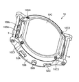
カーラ24は、この例では厚さ1mm程度の或る程度の可撓性および硬さを有する樹脂板(この例では、ポリプロピレン)からなっている。図3(A)、図3(B)によって分かるように、カーラ24は、展開状態では、長手方向Y(左手首90の周方向に相当)に関して押圧カフ23の長さを越えて帯状に延在している。このカーラ24は、図7中に示すように、自然状態では、左手首90を取り巻く周方向Yに沿って湾曲した形状を有する。これにより、カフ構造体20の自然状態での形状が、図2中に示すように、左手首90の周方向Yに沿って湾曲した状態に保たれる。
The
背板22の内周面22aの周縁部、カーラ24の内周面24aの周縁部には、それぞれ被測定部位(この例では、左手首90)から遠ざかる向きに湾曲したアール22r、アール24rが形成されている。これにより、ユーザに対して、カフ構造体20の装着による違和感を与えないようにしている。
At the peripheral edge of the inner
図6に示すように、本体10の裏側には裏蓋10Cが設けられている。裏蓋10Cは、4つの貫通孔10C1,10C2,10C3,10C4を有し、これらの貫通孔10C1,10C2,10C3,10C4を通して、図示しないネジによってケース10Bの裏側に固定されている。ケース10Bの側面の第1ベルト部3の根元部3eで隠れる部分には、フィルタ付き吸排気孔10Bo,10Bo,…が設けられている(第2ベルト部4の根元部4eで隠れる部分でも同様。)。これにより、生活防水機能を実現しながら、ケース10Bの内外間の空気流通が可能になっている。
As shown in FIG. 6, a
図7は、本体10の裏側を、裏蓋10Cを取り外した分解状態で、上述のカーラ24を含めて示している。本体10のケース10B内には、血圧測定要素を搭載するためのインナーケース部材11が収容されている。インナーケース部材11の裏側には、突起11pの周りを取り囲む態様で環状溝11dが形成されている。カーラ24の根元部24fには、環状溝11dに対応した形状をもつリング24oが形成されている。本体10を組み立てる際には、インナーケース部材11の環状溝11dに、カーラ24の根元部24fのリング24oが嵌められる(同時に、インナーケース部材11の突起11pにリング24oが嵌まる。)。そして、インナーケース部材11の裏側と本体10の裏蓋10Cとの間に、後述の2つの流路形成部材(第1の流路形成部材390、第2の流路形成部材380)と重なった状態で、カーラ24の根元部24fが挟持される。
FIG. 7 shows the back side of the
これにより、図2中に示したように、カフ構造体20の一端20f(カーラ24の根元部24f)が本体10に取り付けられる。カフ構造体20の他端20e(カーラ24の先端部24e)は自由端になっている。この結果、カフ構造体20はベルト2の内周面3a,4aに対向し、内周面3a,4aから離間自在になっている。
As a result, as shown in FIG. 2, one
このようにしてカフ構造体20が本体10に取り付けられている場合、本体10にカフ構造体20の一端20fが確実に保持される。また、保守サービスの際には、本体10の裏蓋10Cを開くことによって、ベルト2とは無関係に、本体10に対してカフ構造体20を交換することができる。また、カフ構造体20の長手方向Y(左手首90の周方向に相当)の寸法が、ベルト2とは無関係に、最適寸法に設定され得る。
When the
なお、この血圧計1では、本体10とベルト2とが互いに別々に形成され、本体10に対してベルト2が取り付けられているので、保守サービスの際に、カフ構造体20とは無関係に、本体10に対してベルト2を交換することもできる。
In this
図7中に示した第1の流路形成部材390は、互いに対向して薄板状に広がる2枚のシート板391,392と、これらのシート板391,392を予め定められた間隔(この例では、0.7mm)に保つスペーサ部393とからなっている。同様に、第2の流路形成部材380は、互いに対向して薄板状に広がる2枚のシート板381,382と、これらのシート板381,382を予め定められた間隔に保つスペーサ部383とからなっている。なお、シート板381、スペーサ部383については、図9中に示している(図9では、理解の容易のために、インナーケース部材11から遠い側のシート板392,382の図示が省略されている。図9については後述する。)。第1の流路形成部材390の端部、第2の流路形成部材380の端部に対して、それぞれ横向きピン390p,380pが流体流通可能に一体に取り付けられている。カーラ24を含むカフ構造体20が本体10に取り付けられる際に、押圧カフ23からの可撓性チューブ39が横向きピン390pを介して第1の流路形成部材390に接続される。また、センシングカフ21からの可撓性チューブ38が横向きピン380pを介して第2の流路形成部材380に接続される。
The first flow
第1の流路形成部材390、第2の流路形成部材380は、この例では、エラストマの一体成形によって形成されている。第1の流路形成部材390、第2の流路形成部材380の厚さ寸法は、この例では1.2mmに設定されている。
The first flow
図10は、血圧計1の制御系のブロック構成を示している。血圧計1の本体10には、既述の表示器50、操作部52に加えて、血圧測定を実行するための血圧測定要素として、制御部としてのメインCPU(Central Processing Unit)100、サブCPU101、記憶部としてのメモリ51、加速度センサ54、通信部59、電池53、押圧カフ23の圧力を検出するための第1圧力センサ31、センシングカフ21の圧力を検出するための第2圧力センサ32、ポンプ30、開閉弁33、および、ポンプ30を駆動するポンプ駆動回路35が搭載されている。なお、メインCPU100は主に血圧計1全体の動作を制御し、サブCPU101は主にエア系の動作を制御する。以下では、簡単のため、メインCPU100とサブCPU101とを併せて、単にCPU100と呼ぶ。
FIG. 10 shows a block configuration of the control system of the
表示器50は、この例ではLCD(Liquid Cristal Display)からなり、CPU100からの制御信号に従って、血圧測定結果などの血圧測定に関する情報、その他の情報を表示する。なお、表示器50は、有機ELディスプレイに限られるものではなく、例えば有機EL(Electro Luminescence)ディスプレイなど、他のタイプの表示器50からなっていてもよい。また、表示器50は、LED(Light Emitting Diode)を含んでいてもよい。
The
操作部52は、既述のように、血圧測定の開始または停止を指示するための測定スイッチ52Aと、表示器50の表示画面を予め定められたホーム画面へ戻すためのホームスイッチ52Bと、過去の血圧、活動量などの測定記録を表示器50に表示させる指示を行うための記録呼出スイッチ52Cとを含んでいる。この例では、これらのスイッチ52A〜52Cはプッシュ式スイッチからなり、ユーザによる血圧測定開始又は停止等の指示に応じた操作信号をCPU100に入力する。なお、操作部52は、プッシュ式スイッチに限られるものではなく、例えば感圧式(抵抗式)または近接式(静電容量式)のタッチパネル式スイッチなどであってもよい。また、図示しないマイクロフォンを備えて、ユーザの音声によって血圧測定開始の指示を入力するようにしてもよい。
As described above, the operation unit 52 includes a
メモリ51は、血圧計1を制御するためのプログラムのデータ、血圧計1を制御するために用いられるデータ、血圧計1の各種機能を設定するための設定データ、血圧値の測定結果のデータなどを非一時的に記憶する。また、メモリ51は、プログラムが実行されるときのワークメモリなどとして用いられる。
The
CPU100は、メモリ51に記憶された血圧計1を制御するためのプログラムに従って、制御部として各種機能を実行する。例えば、血圧測定機能を実行する場合は、CPU100は、操作部52の測定スイッチ52Aからの血圧測定開始の指示に応じて、第1圧力センサ31、第2圧力センサ32からの信号に基づいて、ポンプ30および開閉弁33を駆動する制御を行う。また、CPU100は、第2圧力センサ32からの信号に基づいて、血圧値、脈拍などを算出する制御を行う。
The
加速度センサ54は、本体10内に一体に内蔵された3軸加速度センサからなる。この加速度センサ54は、本体10の、互いに直交する3方向の加速度を表す加速度信号をCPU100に出力する。この例では、この加速度センサ54の出力は、活動量を測定するために用いられる。
The
通信部59は、CPU100によって制御されて所定の情報を、ネットワークを介して外部の装置に送信したり、外部の装置からの情報を、ネットワークを介して受信してCPU100に受け渡したりする。このネットワークを介した通信は、無線、有線のいずれでも良い。この実施形態において、ネットワークは、インターネットであるが、これに限定されず、病院内LAN(Local Area Network)のような他の種類のネットワークであってもよいし、USBケーブルなどを用いた1対1の通信であってもよい。この通信部59は、マイクロUSBコネクタを含んでいてもよい。
The
電池53は、この例では、充電可能な2次電池からなっている。電池53は、本体10に搭載された要素、この例では、CPU100、メモリ51、加速度センサ54、通信部59、第1圧力センサ31、第2圧力センサ32、ポンプ30、開閉弁33、および、ポンプ駆動回路35の各要素へ電力を供給する。
The
ポンプ30は、この例では圧電ポンプからなり、CPU100から与えられる制御信号に基づいてポンプ駆動回路35によって駆動される。このポンプ30は、第1の流路を構成する第1の流路形成部材390および可撓性チューブ39を介して、押圧カフ23に流体流通可能に接続されている。ポンプ30は、第1の流路形成部材390および可撓性チューブ39を通して、押圧カフ23に加圧用の流体として空気を供給することができる。なお、このポンプ30には、ポンプ30のオン/オフに伴って開閉が制御される図示しない排気弁が搭載されている。すなわち、この排気弁は、ポンプ30がオンされると閉じて、押圧カフ23内に空気を封入するのを助ける一方、ポンプ30がオフされると開いて、押圧カフ23の空気を可撓性チューブ39および第1の流路形成部材390を通して、大気中へ排出させる。なお、この排気弁は、逆止弁の機能を有し、排出される空気が逆流することはない。
The
このポンプ30は、第2の流路を構成する第2の流路形成部材380および可撓性チューブ38を介して、センシングカフ21に流体流通可能に接続されている。第2の流路(実際には、第1の流路形成部材390と第2の流路形成部材380との間)には、開閉弁(この例では、常開の電磁弁)33が介挿されている。開閉弁33は、CPU100から与えられる制御信号に基づいて開閉(開度)が制御される。この開閉弁33が開状態にあるとき、ポンプ30から第2の流路を通してセンシングカフ21に圧力伝達用の流体として空気を供給して収容させることができる。
The
第1圧力センサ31、第2圧力センサ32は、この例ではそれぞれピエゾ抵抗式圧力センサからなっている。第1圧力センサ31は、第1の流路を構成する第1の流路形成部材390および可撓性チューブ39を介して、押圧カフ23内の圧力を検出する。第2圧力センサ32は、第2の流路を構成する第2の流路形成部材380および可撓性チューブ38を介して、センシングカフ21内の圧力を検出する。
The
なお、図8(本体10の内部を斜め上方から見たところ)に示すように、ポンプ30と第1圧力センサ31とは、本体10内でインナーケース部材11の略中央に配置されている。開閉弁33と第2圧力センサ32とは、インナーケース部材11の周辺に配置されている。図9(本体10の内部を斜め下方から見たところ)に示すように、第1の流路形成部材390は、インナーケース部材11の裏側で、ポンプ30の吐出口30dと、第1圧力センサ31の空気導入口31dと、開閉弁33の入口33iとにまたがって配置されている。第2の流路形成部材380は、インナーケース部材11の裏側で、開閉弁33の出口33eと、第2圧力センサ32の空気導入口32dとにまたがって配置されている。
As shown in FIG. 8 (viewing the inside of the
この血圧計1は、本体10に上述のような血圧測定要素を搭載することによって、小型で一体に構成されている。したがって、ユーザの使い勝手が良い。
The
(血圧測定の動作)
図11は、ユーザが血圧計1によって一実施形態の血圧測定方法を実行して血圧測定を行う際の動作フローを示している。
(Blood pressure measurement operation)
FIG. 11 shows an operation flow when the user executes the blood pressure measuring method of one embodiment by the
図11のステップS1に示すように、ユーザが血圧計1を被測定部位としての左手首90に装着する。この装着の際に、図13Aに示すように、まず、ユーザは、左手首90に、右手99を使ってカフ構造体20を装着する(図12中のステップS21)。ここで、カフ構造体20は、自然状態ではカーラ24によって左手首90の周方向Yに沿って湾曲している。したがって、ユーザは、この例では左手首90が属する側の左半身とは反対側の右半身の手(この例では、右手99)を使って左手首90の外周面にカフ構造体20を嵌め込むことによって、左手首90にカフ構造体20を容易に装着することができる。左手首90にカフ構造体20が装着された状態では、ユーザが右手99をカフ構造体20から離したとしても、カフ構造体20が左手首90を把持することから、左手首90からカフ構造体20(およびベルト2、本体10)が脱落し難い。
As shown in step S1 of FIG. 11, the user wears the
次に、図13Bに示すように、ユーザは、右手99を使って、ベルト2で、左手首90とカフ構造体20とを一括して取り巻く状態にする。具体的には、第1ベルト部3の尾錠5の枠状体5Aに第2ベルト部4の先端部4fに連なる部分を通し、さらに、第2ベルト部4の複数の小穴4w,4w,…のうちのいずれか一つに尾錠5のつく棒5Bを挿通する。これにより、図13Cに示すように、第1ベルト部3と第2ベルト部4とを締結する(図12中のステップS22)。これにより、本体10から延在するベルト2が左手首90を取り巻くとともに、本体10に一端20fが取り付けられた帯状のカフ構造体20がベルト2よりも左手首90に近い内周側に配置された状態になる。
Next, as shown in FIG. 13B, the user uses the
ここで、この血圧計1では、カフ構造体20がベルト2の内周面3a,4aから離間自在であるとともに、カフ構造体20の一端20fと反対の側の他端20eは自由端になっている。したがって、第1ベルト部3と第2ベルト部4とを締結する際に、ベルト2からカフ構造体20が内向きの力を受けて、左手首90の外周面に丁度沿うようにカフ構造体20がスライドまたは変形し得る。これにより、装着状態では、左手首90の外周面に対して、カフ構造体20、ベルト2がこの順に略密接した状態、つまり、左手首90を全体として帯状に取り巻く状態となる。このようにして、この血圧計1は、左手首90に対して容易に装着され得る。
Here, in this
詳しくは、図14に示すように、この装着状態では、カフ構造体20に含まれたカーラ24の内周側で、袋状の押圧カフ23が、左手首90の周方向Yに沿って延在する。また、カフ構造体20に含まれた袋状のセンシングカフ21が、押圧カフ23よりも内周側に配置されて左手首90に接し、かつ、左手首90の動脈通過部分90aを横切るように周方向Yに延在する。さらに、カフ構造体20に含まれた背板22が、押圧カフ23とセンシングカフ21との間に介挿され左手首90の周方向Yに沿って延在する。なお、図14では、本体10とベルト2の図示は省略されている。図14中には、左手首90の橈骨93、尺骨94、橈骨動脈91、尺骨動脈92、および腱96が示されている。
Specifically, as shown in FIG. 14, in this mounted state, the bag-shaped
次に、ユーザが本体10に設けられた操作部52の測定スイッチ52Aを押すと(図11のステップS2)、CPU100は、処理用メモリ領域を初期化する(図11のステップS3)。また、CPU100は、ポンプ駆動回路35を介してポンプ30をオフし、ポンプ30に内蔵された排気弁を開くとともに、開閉弁33を開状態に維持して、押圧カフ23内およびセンシングカフ21内の空気を排気する。続いて、第1圧力センサ31、第2圧力センサ32の0mmHgの調整を行う制御を行う。
Next, when the user presses the
次に、CPU100は加圧制御部および流体収容制御部として働いて、ポンプ駆動回路35を介してポンプ30をオンし(図11のステップS4)、開閉弁33を開状態に維持して、押圧カフ23およびセンシングカフ21の加圧を開始する(図11のステップS5)。加圧過程では、第1圧力センサ31、第2圧力センサ32によって押圧カフ23、センシングカフ21の圧力をそれぞれモニタしながら、ポンプ駆動回路35を介してポンプ30を駆動する。これにより、第1の流路(第1の流路形成部材390および可撓性チューブ39)を通して押圧カフ23に、また、第2の流路(第2の流路形成部材380および可撓性チューブ38)を通してセンシングカフ21に、それぞれ空気を送る制御を行う。
Next, the
次に、図11のステップS6で、CPU100は流体収容制御部として働いて、センシングカフ21の圧力が所定の圧力(この例では、15mmHg)に到達したか、もしくは、ポンプ30の駆動時間が所定の時間(この例では、3秒間)だけ経過した否かを判断する。この判断を行う理由は、センシングカフ21内に適量の空気が収容されたか否かを確認するためである。図11のステップS6でNOならば、センシングカフ21の圧力が所定の圧力に到達するか、もしくは、ポンプ30の駆動時間が所定の時間だけ経過するまで待つ。なお、センシングカフ21内に収容される圧力伝達用の流体の「適量」がどの程度の量であるかについては、後述する。
Next, in step S6 of FIG. 11, the
図11のステップS6でYESならば、センシングカフ21に適量の空気が収容されたと判断される。すると、図11のステップS7で、CPU100は加圧制御部として働いて、開閉弁33を閉状態にして、ポンプ30から第1の流路を通して押圧カフ23に空気を供給する制御を継続する。これにより、押圧カフ23を膨張させるとともに圧力を徐々に加圧して、左手首90を圧迫していく。このとき、背板22が、押圧カフ23からの押圧力をセンシングカフ21へ伝える。センシングカフ21は、左手首90(動脈通過部分90aを含む。)を圧迫する。この加圧過程で、CPU100は、血圧値を算出するために、第2圧力センサ32によって、センシングカフ21の圧力Pc、すなわち、左手首90の動脈通過部分90aの圧力をモニタし、変動成分としての脈波信号Pmを取得する。図16中に、この加圧過程で得られるセンシングカフ21の圧力Pc、脈波信号Pmの波形を例示している。
If YES in step S6 of FIG. 11, it is determined that an appropriate amount of air is contained in the
ここで、図15A、図15Bは、センシングカフ21に適量の空気が収容され、開閉弁33が閉じられた加圧状態での、左手首90の長手方向(カフの幅方向Xに相当)に沿った断面を模式的に示している。図15Aは、左手首90の腱96が通る部分の断面(図14中のXVA−XVA線矢視断面に相当)を示している。一方、図15Bは、左手首90の橈骨動脈91が通る部分の断面(図14中のXVB−XVB線矢視断面に相当)を示している。図15Bに示すように、左手首90の橈骨動脈91が通る部分は比較的柔らかいので、センシングカフ21の第1のシート21Aと第2のシート21Bとの間に、空気が存在する隙間21wが残っている。したがって、センシングカフ21のうち橈骨動脈91に対向する部分は、左手首90の動脈通過部分90aの圧力を反映することができる。一方、図15Aに示すように、左手首90の腱96が通る部分は比較的硬いので、センシングカフ21のうち幅方向Xに関して略中央に相当する部分では、第1のシート21Aと第2のシート21Bとが互いに接している。しかし、センシングカフ21のうち幅方向Xに関して両側の縁部21m,21mに連なる箇所では、既述のように長手方向Y(左手首90の周方向に相当)に沿って延在する弛み21r,21rが設けられていることから、長手方向Yに沿って空気が存在する隙間21w′,21w′が残っている。この結果、センシングカフ21に収容された空気が、隙間21w′,21w′を通して、センシングカフ21の長手方向Yに沿って流通し得る。したがって、センシングカフ21は、左手首90の動脈通過部分90aに加えられた圧力を、空気(圧力伝達用の流体)の圧力として本体10内の第2圧力センサ32へ首尾良く伝達することができる。
Here, FIGS. 15A and 15B show the
次に、図11のステップS8で、CPU100は血圧算出部として働いて、この時点で取得されている脈波信号Pmに基づいて、オシロメトリック法により公知のアルゴリズムを適用して血圧値(収縮期血圧SBPと拡張期血圧DBP)の算出を試みる。
Next, in step S8 of FIG. 11, the
この時点で、データ不足のために未だ血圧値を算出できない場合は(ステップS9でNO)、カフ圧が上限圧力(安全のために、例えば300mmHgというように予め定められている。)に達していない限り、ステップS7〜S9の処理を繰り返す。 At this point, if the blood pressure value cannot be calculated yet due to lack of data (NO in step S9), the cuff pressure has reached the upper limit pressure (for safety, for example, 300 mmHg is predetermined). Unless otherwise, the processes of steps S7 to S9 are repeated.
このようにして血圧値の算出ができたら(ステップS9でYES)、CPU100は、ポンプ30を停止し(ステップS10)、開閉弁33を開いて(ステップS11)、押圧カフ23内、センシングカフ21内の空気を排気する制御を行う。そして最後に、血圧値の測定結果を表示器50に表示する(ステップS12)。
When the blood pressure value can be calculated in this way (YES in step S9), the
なお、血圧算出は、押圧カフ23の加圧過程でなく、減圧過程で行われてもよい。
The blood pressure calculation may be performed not in the pressurizing process of the
このように、この血圧計1では、血圧測定の都度、センシングカフ21に空気を収容し、第2圧力センサ32は、押圧カフ23とは別に、センシングカフ21の圧力Pc、すなわち、左手首90の動脈通過部分90aの圧力自体を検出する。したがって、ベルト2とカフ構造体20(適宜、単に「カフ」と総称する。)の幅方向Xの寸法を小さく(例えば25mm程度に)設定した結果、加圧時に押圧カフ23が厚さ方向に大きく膨張して圧迫ロスが発生した場合であっても、血圧を精度良く測定できる。また、装着状態では、センシングカフ21は、左手首90の動脈通過部分90aを横切るように周方向Yに延在する。したがって、ユーザが実際に血圧計1を左手首90に装着する際に、左手首90の周方向Yに関して本体10とともにカフが或る程度位置ずれしたとしても、左手首90の動脈通過部分90aからセンシングカフ21が外れることはない。したがって、実際の血圧に対して血圧測定値がばらつくのを防止でき、この結果、血圧を精度良く測定できる。
As described above, in the
なお、上の例では、血圧測定の都度、センシングカフ21内に圧力伝達用の流体としての空気を収容し、測定終了後に排気しているが、これに限られるものではない。この血圧計1の製造段階でセンシングカフ21に圧力伝達用の流体を収容し、封じ切りにしても良い。
In the above example, air as a fluid for pressure transmission is accommodated in the
(センシングカフ内に収容される圧力伝達用の流体の適量)
図17は、センシングカフ21に収容される圧力伝達用の流体として水を用い、センシングカフ21に収容される水量を可変して設定したときの血圧測定誤差(平均値)を示している。ここで、血圧測定誤差とは、或るユーザ(被験者)について、血圧計1によって測定された血圧値(収縮期血圧SBP)から、標準的な(正確な)血圧計によって測定された血圧値(収縮期血圧SBP)(これを「リファレンス血圧値」と呼ぶ。)を差し引いて得られた差分を意味している。すなわち、
(血圧測定誤差)=(血圧計1により測定された血圧値)−(リファレンス血圧値)
である。この図17から分かるように、センシングカフ21に収容される水量が0.26ml±0.05mlの範囲waであれば、血圧測定誤差±5mmHg以内であり、適量であると考えられる。
(Appropriate amount of pressure transfer fluid contained in the sensing cuff)
FIG. 17 shows a blood pressure measurement error (mean value) when water is used as the pressure transmission fluid contained in the
(Blood pressure measurement error) = (Blood pressure value measured by Sphygmomanometer 1)-(Reference blood pressure value)
Is. As can be seen from FIG. 17, if the amount of water contained in the
図17では、水量がその適量範囲waを超えると、血圧測定誤差がプラス側に大きくなっている。この理由は、図14に示す断面で、腱96などの固い部分の上にも水が介在することで、圧迫されたときにセンシングカフ21の内圧が上がってしまうこと、および、左手首90のうち橈骨動脈91および尺骨動脈92が通る部分は比較的柔らかいので、その部分に水が必要以上にあることで、センシングカフ21が膨らみ、膨らませる張力の分だけセンシングカフ21の内圧が上がってしまうからである、と考えられる。また、図17では、水量がその適量範囲waを下回ると、血圧測定誤差がマイナス側に大きくなっている。この理由は、動脈周辺の水量が少なくなりすぎるからである、と考えられる。
In FIG. 17, when the amount of water exceeds the appropriate amount range wa, the blood pressure measurement error becomes large on the positive side. The reason for this is that in the cross section shown in FIG. 14, water also intervenes on a hard portion such as the
この結果、この例では、センシングカフ21に収容される圧力伝達用の流体は、0.26ml±0.05mlの範囲waが適量であると考えられる。既述の図11のステップS6における、センシングカフ21の圧力が所定の圧力(この例では、15mmHg)に到達したか、もしくは、ポンプ30の駆動時間が所定の時間(この例では、3秒間)だけ経過した否かという判断の基準は、このセンシングカフ21に収容される圧力伝達用の流体としての空気の量が0.26ml±0.05mlの範囲waになる条件を満たすように設定されている。
As a result, in this example, the pressure transfer fluid contained in the
なお、当然ながら、センシングカフ21に収容される圧力伝達用の流体の適量は、センシングカフ21のサイズなどに依存する。
As a matter of course, the appropriate amount of the pressure transmission fluid contained in the
(検証結果)
図18の散布図は、複数のユーザ(この例では、収縮期血圧SBPが97mmHgから149mmHgまでの5人の被験者についてそれぞれ3回ずつ測定)について、センシングカフ21に収容される圧力伝達用の流体としての水量を、「水量少」=0.16ml、「適量」=0.3ml、「水量多」=0.8mlに可変して設定した場合の、リファレンス血圧値と血圧測定誤差との関係を示している。水量が「適量」であれば、図中に□印で示すように、複数のユーザについて血圧測定誤差が少なくなっている。これに対して、「水量多」であれば、図中に×印で示すように、複数のユーザについて血圧測定誤差がプラス側に大きくなっている。「水量少」であれば、図中に◇印で示すように、複数のユーザについて血圧測定誤差がマイナス側に大きくなっている。
(inspection result)
The scatter diagram of FIG. 18 shows the fluid for pressure transmission contained in the
この検証結果から、この発明の血圧計1によれば、腱96、橈骨93、および尺骨94が存在する手首を被測定部位として、袋状のセンシングカフを用いて血圧を測定する場合でも、血圧を精度良く測定できることを確認できた、と言える。
From this verification result, according to the
特に、複数のユーザがそれぞれ実際に血圧計1を左手首90に装着して血圧測定を行う場合、ユーザによっては、橈骨動脈91および尺骨動脈92の2つの動脈が存在する柔らかい部分の面積が異なる。ここで、図18の検証結果では、水量が適量であれば、複数のユーザについて血圧測定誤差が抑えられている。したがって、この血圧計1では、橈骨動脈91および尺骨動脈92の2つの動脈が存在する柔らかい部分の面積が異なる場合でも、血圧を精度良く測定できることを確認できた、と言える。
In particular, when a plurality of users actually wear the
(背板とセンシングカフの幅方向寸法)
図19は、カーラ24、押圧カフ23、背板22、およびセンシングカフ21の幅方向Xにおける寸法の関係を示す模式図である。図19においては、カーラ24、押圧カフ23、背板22、およびセンシングカフ21の幅方向Xにおける中心位置を、X座標の原点に合わせている。図20(A)は、押圧カフにより300mmHgの圧力を背板22に与えたときの皮膚表面(左手首90)の圧力分布と血管周囲の圧力分布のシミュレーションの結果を示す図である。図20(B)は、押圧カフにより300mmHgの圧力を皮膚表面(左手首90)に与えたときの皮膚表面の圧力分布と血管周囲の圧力分布のシミュレーションの結果を示す図である。図20(A),(B)におけるX座標位置は、図19におけるX座標位置に対応している。
(Width direction dimension of back plate and sensing cuff)
FIG. 19 is a schematic view showing the relationship between the dimensions of the
図20(B)に示すように、背板22を設けず、押圧カフ23により被測定部位を押圧した場合には、皮膚表面位置と血管位置における圧力はほぼ一致しており、中央部が高くなり、幅方向Xの縁部に向かうほど低くなっている。しかし、図20(A)に示すように、背板22を設け、押圧カフ23と背板22とにより被測定部位を押圧した場合には、皮膚表面位置と血管位置との圧力は、中央部では一致しており、均一になっている。しかし、幅方向Xの縁部22fの近くでは、皮膚表面位置の圧力が血管位置の圧力に比べて極めて高くなっており、血管位置における圧力とのずれが生じている。これは、図19に示すように、シミュレーションに用いた背板22が板状の部材であり、幅方向Xの縁部22fにエッジ22cを有する形状としているため、このエッジ22cによる応力集中が発生したためであると考えられる。このように、背板22を介して押圧した場合には、圧力が均一な範囲は押圧カフ23のみの場合に比べて広がるものの、応力集中により皮膚表面位置と血管位置との圧力にずれが生じる。したがって、センシングカフ21の幅方向Xの寸法を、背板22の幅方向Xの寸法と同じにした場合には、センシングカフ21の被測定部位に対する幅方向Xの圧力は、皮膚表面位置と血管位置とでずれが生じ、測定する血圧値に誤差が発生してしまう。
As shown in FIG. 20 (B), when the part to be measured is pressed by the
そこで、本実施形態においては、図3(B)にも示したように、カーラ24、押圧カフ23、背板22、およびセンシングカフ21のそれぞれの幅方向Xの寸法を、W1=28mm、W2=25mm、W3=23mm、およびW4=15mmに設定している。つまり、本実施形態においては、センシングカフ21の幅方向Xの寸法よりも、背板22の幅方向Xの寸法を大きくしている。このように構成することにより、背板22がエッジ22cを有する形状である場合でも、図20(B)において皮膚表面位置と血管位置との圧力が一致し、圧力が均一な領域でセンシングカフ21を押圧することができる。その結果、センシングカフ21の被測定部位における皮膚表面位置と血管位置との圧力のずれがなく、被測定部位に対する押圧力が均一なものとなり、測定する血圧値における誤差の発生を防ぐことができる。したがって、血圧計1によれば、血圧を精度良く測定できる。
Therefore, in the present embodiment, as shown in FIG. 3B, the dimensions of the
(背板の幅方向の縁部の構成)
図21は、幅方向Xにおける両側の縁部22fの被測定部位に対向する面22gを、先端に向かうに連れて被測定部位から遠ざかる向きに湾曲させた背板22を示す模式図である。図22は、幅方向Xにおける両側の縁部22fの被測定部位に対向する面22gを、被測定部位から遠ざかる向きに湾曲させた背板22を示す模式図である。図21および図22においては、背板22およびセンシングカフ21の幅方向Xにおける中心位置を、X座標の原点に合わせている。図23は、押圧カフ23により300mmHgの圧力を図21の背板22に与えたときの皮膚表面の圧力分布と血管周囲の圧力分布のシミュレーションの結果を示す図である。図24は、押圧カフ23により300mmHgの圧力を図22の背板22に与えたときの皮膚表面の圧力分布と血管周囲の圧力分布のシミュレーションの結果を示す図である。
(Structure of the edge in the width direction of the back plate)
FIG. 21 is a schematic view showing a
図21のように、背板22において、幅方向Xにおける両側の縁部22fの被測定部位に対向する面22gを、先端に向かうに連れて被測定部位から遠ざかる向きに湾曲させた場合には、図23に示すように、被測定部位の皮膚表面位置と血管位置とにおける圧力は、ほぼ一致することが分かる。これに対して、図22のように、背板22において、幅方向Xにおける両側の縁部22fの被測定部位に対向する面22gを、被測定部位から遠ざかる向きに湾曲させ、底面22eと面22gとの間にエッジ22cを形成した場合には、図24に示すように、被測定部位の皮膚表面位置における圧力が、エッジ22cの付近で血管位置における押圧力よりも高くなっていることが分かる。これは、図22に示す背板22では、面22gが被測定部位から遠ざかる向きに湾曲しているものの、エッジ22cが形成されているために、エッジ22cによる応力集中が発生したものと考えられる。
As shown in FIG. 21, when the
したがって、被測定部位の皮膚表面位置と血管位置とにおいて、センシングカフ21の被測定部位に対する圧力のずれをなくし、圧力をより均一にするためには、上述のようにセンシングカフ21の幅方向Xの寸法よりも、背板22の幅方向Xの寸法を大きくすると共に、背板22において、幅方向Xにおける両側の縁部22fの被測定部位に対向する面22gを、先端に向かうに連れて被測定部位から遠ざかる向きに湾曲させることが好ましいことが分かった。このように構成すれば、被測定部位の皮膚表面位置と血管位置とにおいて、センシングカフ21の被測定部位に対する圧力のずれをなくし、圧力がより均一なものとなり、測定する血圧値における誤差を小さくし、血圧を精度良く測定することができる。なお、面22gを湾曲させるのは、面22gをアール形状に加工してもよいし、また、テーパ状に加工してもよい。つまり、背板22の両側の縁部22fを、それぞれ先端に向かうに連れて次第に薄厚にすることにより、エッジによる応力集中の影響を低減することができる。
Therefore, in order to eliminate the pressure deviation of the
図25は、幅方向Xにおける両側の縁部22fの被測定部位に対向する面22gを、先端に向かうに連れて被測定部位から遠ざかる向きに湾曲させた背板22の幅方向寸法を、センシングカフ21の幅方向寸法と同じにした場合の模式図である。このように構成した場合には、図19のようにセンシングカフ21の幅方向Xの寸法よりも、背板22の幅方向Xの寸法を大きくした場合に比べて、被測定部位の皮膚表面位置と血管位置とにおいて、センシングカフ21の被測定部位に対する圧力のずれが生じ、圧力の均一性は損なわれる。これは、背板22の底面22eがセンシングカフ21の幅方向Xの全域にわたって平面である場合に比べて、湾曲された縁部22fによって背板22の幅方向Xにおける圧力が変化するためである。しかしながら、図25に示す背板22においては、湾曲された縁部22fと底面22eとの間にエッジが存在していないために、被測定部位における応力集中は発生せず、測定する血圧値における誤差もそれほど大きくない。したがって、図25のように、背板22において、幅方向Xにおける両側の縁部22fの面を先端に向かうに連れて被測定部位から遠ざかる向きに湾曲させた場合には、背板22の幅方向寸法を、センシングカフ21の幅方向寸法と同じにしても、血圧を精度良く測定することができる。
FIG. 25 senses the widthwise dimension of the
上に述べた実施形態では、背板22の内周面22a、外周面22bに、幅方向Xに延びる断面V字状またはU字状の溝22d1,22d2が、長手方向Yに関して互いに離間して複数平行に設けられているものとした。しかしながら、これに限られるものではない。背板は、この背板が全体として被測定部位の周方向(長手方向Y)に沿って湾曲し得るように、長手方向Yに関して互いに分離した複数の小片の集合からなり、それらの複数の小片の集合が、被測定部位の周方向(長手方向Y)に関してセンシングカフ21の長さを越える範囲にわたって配置されているものとしてもよい。この場合も、上述の背板22におけるのと実質的に同じ効果を奏することができる。
In the embodiment described above, grooves 22d1, 22d2 having a V-shaped or U-shaped cross section extending in the width direction X are separated from each other in the longitudinal direction Y on the inner
上に述べた実施形態では、血圧計が装着される被測定部位は左手首90であるものとした。しかしながら、これに限られるものではない。この発明の血圧計を、図1、図2に示した血圧計1に対して光学対称に構成して、右手首に装着されるようにしても良い。また、被測定部位は、上腕、下肢などの手首以外の部位であっても良い。
In the embodiment described above, the site to be measured to which the sphygmomanometer is attached is assumed to be the
また、上に述べた実施形態では、本体10とベルト2とが互いに別々に形成され、本体10に対してベルト2が取り付けられている構成にした。しかしながら、これに限られるものではない。本体10とベルト2とが一体成形されていても良い。
Further, in the embodiment described above, the
また、上に述べた実施形態では、ベルト2の第1ベルト部3と第2ベルト部4とが、尾錠5によって締結または開放されるものとした。しかしながら、これに限られるものではない。例えば、第1ベルト部3と第2ベルト部4とが、開閉可能な三つ折れ式バックルを介して互いに連結されていても良い。
Further, in the embodiment described above, the
上に述べた実施形態では、カフ構造体20が、カーラ24を備える例について説明した。しかし、本発明はこの例に限定されるものではなく、カーラ24を省略してもよい。この場合は、ベルト2を1つの帯状体で形成し、帯状体の内周面に沿って押圧カフ23を配置し、この押圧カフ23の内周面に沿って背板22を配置して、この背板22の内周面に沿ってセンシングカフ21を配置すればよい。この場合には、上述したベルト2と、押圧カフ23とが、手首へ向かって押圧力を発生可能な押圧部材として働き、これらの押圧部材によって背板22を被測定部位としての手首へ向かって押圧し、背板22と手首の間に介挿されたセンシングカフ21を介して手首を圧迫する。ベルト2については、例えば本体10の裏蓋10Cに開閉可能な三つ折れ式バックルを備え、ベルト2の端部と三つ折れ式バックルとを連結すればよい。
In the embodiment described above, an example in which the
上に述べた実施形態では、図11のステップS6に示すセンシングカフ21の加圧工程において、センシングカフ21の圧力が15mmHgに到達するまでポンプ30を駆動し、もしくは、ポンプ30の駆動時間を3秒間とした。しかし、本発明はこの例に限定されるものではなく、センシングカフ21の圧力が、例えば5mmHgに到達するまでポンプ30を駆動し、センシングカフ21内に流体を充填させてから、徐々にセンシングカフ21内の流体の量を最適化するようにしてもよい。または、まず高めの圧力、例えば30mmHgに到達するまでポンプ30によりセンシングカフ21内に空気を充填させて、その後ポンプ30を停止して排気弁を開き、センシングカフ21の圧力を低めの圧力、例えば15mmHgまで圧力を低下させてから排気弁を閉じて、センシングカフ21内の流体容量を最適化してもよい。この場合には、排気弁をポンプ30とは別体に設け、排気弁を駆動する弁駆動回路をCPU100により制御可能に設ければよい。
In the embodiment described above, in the pressurizing step of the
上に述べた実施形態では、センシングカフ21は被測定部位としての左手首90に直接接する例について説明としたが、これに限られるものではない。センシングカフ21は他の部材(例えばカバー部材)を介して間接的に左手首90に接してもよい。
In the above-described embodiment, the example in which the
上に述べた実施形態では、押圧部材の例として、ベルト2、カーラ24、および押圧カフ23を挙げたが、本発明はこの例に限られず、機械式に厚さ方向に拡張する押圧部材でもよい。
In the above-described embodiment, the
上に述べた実施形態では、ポンプ30を本体10に備える例について説明したが、本発明はこの例に限られず、ベルト2およびカフ構造体20を含むカフと、卓上に置かれる本体とを備え、この本体にポンプを備えてもよい。この場合には、カフと、本体とを、細長いチューブを介して接続し、本体からカフに流体を供給すればよい。
In the above-described embodiment, an example in which the
また、上述の実施形態では、血圧計1に搭載されたCPU100が流体収容制御部、加圧制御部、および、血圧算出部として働いて、血圧測定(図11の動作フロー)を実行するものとした。しかしながら、これに限られるものではない。例えば、血圧計1の外部に設けられたスマートフォンなどの実質的なコンピュータ装置が、流体収容制御部、加圧制御部、および、血圧算出部として働いて、ネットワーク900を介して、血圧計1に血圧測定(図11の動作フロー)を実行させるようにしてもよい。
Further, in the above-described embodiment, the
以上の実施形態は例示であり、この発明の範囲から離れることなく様々な変形が可能である。上述した複数の実施の形態は、それぞれ単独で成立し得るものであるが、実施の形態同士の組みあわせも可能である。また、異なる実施の形態の中の種々の特徴も、それぞれ単独で成立し得るものであるが、異なる実施の形態の中の特徴同士の組みあわせも可能である。 The above embodiment is an example, and various modifications can be made without departing from the scope of the present invention. Although the plurality of embodiments described above can be established independently, combinations of the embodiments are also possible. Further, although various features in different embodiments can be established independently, it is also possible to combine features in different embodiments.
1 血圧計
2 ベルト
3 第1ベルト部
4 第2ベルト部
10 本体
20 カフ構造体
21 センシングカフ
22 背板
23 押圧カフ
24 カーラ
30 ポンプ
31 第1圧力センサ
32 第2圧力センサ
33 開閉弁
91 橈骨動脈
92 尺骨動脈
93 橈骨
94 尺骨
96 腱
1
Claims (14)
上記センシングカフに対して、上記被測定部位とは反対側の面に沿って配置された背板と、
上記背板を上記被測定部位へ向けて押圧するための押圧部材と、
上記センシングカフに収容された流体の圧力に基づいて血圧を算出する血圧算出部と、
を備え、
上記センシングカフが取り巻くべき上記被測定部位の周方向に対して垂直な長手方向に関して、上記センシングカフの上記長手方向に沿った幅方向の寸法よりも、上記背板の上記幅方向の寸法が大きい、
ことを特徴とする血圧計。 A bag-shaped sensing cuff that should be worn around the area to be measured,
With respect to the sensing cuff, a back plate arranged along the surface opposite to the measurement site, and
A pressing member for pressing the back plate toward the measurement site, and
A blood pressure calculation unit that calculates blood pressure based on the pressure of the fluid contained in the sensing cuff,
With
With respect to the longitudinal direction perpendicular to the circumferential direction of the measurement site to surrounding the above sensing cuff, than the longitudinal direction in the width direction of the dimension along the sensing cuff, the dimensions of the upper Symbol width direction of the back plate large,
A sphygmomanometer characterized by that.
上記背板の上記幅方向における両側の縁部の上記被測定部位に対向する面は、先端に向かうに連れて上記被測定部位から遠ざかる向きに湾曲している、
ことを特徴とする血圧計。 In the sphygmomanometer according to claim 1.
The surfaces of the back plates on both sides in the width direction facing the measured portion are curved in a direction away from the measured portion toward the tip end.
A sphygmomanometer characterized by that.
上記両側の縁部は、それぞれ先端に向かうに連れて次第に薄厚になっている、
ことを特徴とする血圧計。 In the blood pressure monitor according to claim 2.
The edges on both sides of the above gradually become thinner toward the tip,
A sphygmomanometer characterized by that.
上記背板は、上記周方向に関して上記センシングカフの長さを越えて帯状に延在し、
上記背板は、上記周方向に沿って湾曲し得るように、この背板の幅方向に延びる断面V字状またはU字状の溝を、この背板の長手方向に関して互いに離間して複数平行に有することを特徴とする血圧計。 In the sphygmomanometer according to any one of claims 1 to 3.
The back plate extends in a strip shape beyond the length of the sensing cuff in the circumferential direction.
The back plate has a plurality of parallel V-shaped or U-shaped grooves extending in the width direction of the back plate, which are separated from each other in the longitudinal direction of the back plate so that the back plate can be curved along the circumferential direction. A sphygmomanometer characterized by having in.
上記背板は、この背板が全体として上記周方向に沿って湾曲し得るように、上記周方向に関して互いに分離した複数の小片の集合からなり、
上記複数の小片の集合が、上記周方向に関して上記センシングカフの長さを越える範囲にわたって配置されていることを特徴とする血圧計。 In the sphygmomanometer according to any one of claims 1 to 3.
The backboard consists of a collection of pieces separated from each other with respect to the circumferential direction so that the backboard can be curved along the circumferential direction as a whole.
A sphygmomanometer characterized in that a set of the plurality of small pieces is arranged over a range exceeding the length of the sensing cuff in the circumferential direction.
上記センシングカフは、圧力伝達用の流体を収容可能に袋状に構成され、上記被測定部位の動脈通過部分を横切るように上記周方向に延在し、
上記押圧部材は、
上記被測定部位を上記周方向に取り巻いて装着されるべきベルトと、
上記ベルトの内周面に対向して配置され、加圧用の流体の供給を受けて上記被測定部位を圧迫するために、上記周方向に沿って延在する袋状の押圧カフと、を含む、
ことを特徴とする血圧計。 In the sphygmomanometer according to any one of claims 1 to 5.
The sensing cuff is configured in a bag shape to accommodate a fluid for pressure transmission, and extends in the circumferential direction so as to cross the arterial passage portion of the measurement site.
The pressing member
A belt that surrounds the part to be measured in the circumferential direction and should be worn.
Includes a bag-shaped pressing cuff that is arranged to face the inner peripheral surface of the belt and extends along the circumferential direction in order to receive the supply of a pressurizing fluid and press the measured portion. ,
A sphygmomanometer characterized by that.
ポンプを搭載した本体を備え、
上記ベルトは、上記本体から延在している、
ことを特徴とする血圧計。 In the sphygmomanometer according to claim 6.
Equipped with a main body equipped with a pump
The belt extends from the main body,
A sphygmomanometer characterized by that.
上記押圧カフ、上記背板、および上記センシングカフは、帯状で、上記本体に一端が取り付けられたカフ構造体を構成し、
このカフ構造体は、さらに、上記押圧カフの外周面に沿って、このカフ構造体の自然状態での形状を、上記周方向に沿って湾曲した状態に保つためのカーラを備えた、
ことを特徴とする血圧計。 In the blood pressure monitor according to claim 7.
The pressing cuff, the back plate, and the sensing cuff form a cuff structure that is strip-shaped and has one end attached to the main body.
The cuff structure is further provided with a carla for keeping the natural shape of the cuff structure in a curved state along the circumferential direction along the outer peripheral surface of the pressing cuff.
A sphygmomanometer characterized by that.
上記カフ構造体の上記一端をなす上記カーラの上記本体側の根元部が、上記本体内に設けられた部材と上記本体の裏蓋との間に挟持され、これにより、上記カフ構造体の上記一端が上記本体に取り付けられていることを特徴とする血圧計。 In the blood pressure monitor according to claim 8.
The root portion of the carla on the main body side, which forms one end of the cuff structure, is sandwiched between the member provided in the main body and the back cover of the main body, whereby the cuff structure is said to be described. A sphygmomanometer characterized in that one end is attached to the main body.
上記カフ構造体の上記一端と反対の側の他端は自由端であることを特徴とする血圧計。 In the sphygmomanometer according to claim 8 or 9.
A sphygmomanometer characterized in that the other end of the cuff structure on the side opposite to the one end is a free end.
上記押圧部材によって上記センシングカフを介して上記被測定部位を圧迫する制御を行う加圧制御部と、
上記押圧部材および上記センシングカフが上記被測定部位に装着された装着状態で、上記センシングカフに上記圧力伝達用の流体を供給して収容させる制御を行う流体収容制御部と、を備え、
上記本体は、
上記ポンプと上記押圧カフとを流体流通可能に接続する第1の流路と、
上記ポンプまたは第1の流路と上記センシングカフとを流体流通可能に接続し、かつ、開閉弁が介挿された第2の流路と
を搭載し、
上記流体収容制御部は、上記装着状態で、上記開閉弁を開状態にして、上記ポンプまたは第1の流路から上記第2の流路を通して上記センシングカフに上記圧力伝達用の流体を供給して収容させ、
上記加圧制御部は、上記センシングカフに上記圧力伝達用の流体が収容された後、上記開閉弁を閉状態にして、上記ポンプから上記第1の流路を通して上記押圧カフに上記加圧用の流体を供給して上記被測定部位を圧迫することを特徴とする血圧計。 In the sphygmomanometer according to any one of claims 7 to 10.
A pressurizing control unit that controls the pressing member to press the area to be measured via the sensing cuff.
The pressing member and in mounting state of being mounted the sensing cuff to the measuring unit position, and a fluid containing a control unit which performs control to accommodate supplying the fluid for the pressure transmitted to the sensing cuff,
The above body is
A first flow path that connects the pump and the pressing cuff so that fluid can flow, and
A second flow path in which the pump or the first flow path and the sensing cuff are connected so that fluid can flow and an on-off valve is inserted is mounted.
In the mounted state, the fluid storage control unit opens the on-off valve and supplies the fluid for pressure transmission from the pump or the first flow path to the sensing cuff through the second flow path. To accommodate
After the fluid for pressure transmission is accommodated in the sensing cuff, the pressurization control unit closes the on-off valve and presses the press cuff from the pump through the first flow path. A sphygmomanometer characterized in that a fluid is supplied to press the site to be measured.
上記本体は、上記加圧制御部と、上記流体収容制御部と、上記血圧算出部と、を搭載している、
ことを特徴とする血圧計。 In the blood pressure monitor according to claim 11.
The main body is equipped with the pressurization control unit, the fluid accommodation control unit, and the blood pressure calculation unit.
A sphygmomanometer characterized by that.
上記センシングカフに対して、上記被測定部位とは反対側の面に沿って配置され、上記センシングカフが取り巻くべき上記被測定部位の周方向に対して垂直な長手方向に関して、上記センシングカフの上記長手方向に沿った幅方向の寸法よりも、上記幅方向の寸法が大きい背板と、
上記背板を上記被測定部位へ向けて押圧するための押圧部材と、を備える血圧計により、上記被測定部位の血圧を測定する血圧測定方法であって、
上記センシングカフに流体を収容し、
上記センシングカフに収容された流体の圧力に基づいて血圧を算出する、
ことを特徴とする血圧測定方法。 A bag-shaped sensing cuff that should be worn around the area to be measured,
The sensing cuff is arranged along a surface opposite to the measured portion with respect to the sensing cuff, and the sensing cuff is to be surrounded by the sensing cuff in a longitudinal direction perpendicular to the circumferential direction of the measured portion. A back plate whose width direction is larger than the width direction along the longitudinal direction,
A pressing member for pressing toward the back plate to the measuring site, the blood pressure monitor Ru provided with, a blood pressure measurement method for measuring the blood pressure of the measurement site,
The fluid is contained in the above sensing cuff,
The blood pressure is calculated based on the pressure of the fluid contained in the sensing cuff.
A blood pressure measurement method characterized by this.
上記血圧測定構造は、
被測定部位を取り巻いて装着されるべき袋状のセンシングカフと、
上記センシングカフに対して、上記被測定部位とは反対側の面に沿って配置された背板と、
上記背板を上記被測定部位へ向けて押圧するための押圧部材と、
上記センシングカフに収容された流体の圧力に基づいて血圧を算出する血圧算出部と、
を備え、
上記センシングカフが取り巻くべき上記被測定部位の周方向に対して垂直な長手方向に関して、上記センシングカフの上記長手方向に沿った幅方向の寸法よりも、上記背板の上記幅方向の寸法が大きい、
ことを特徴とする機器。 A device that includes a blood pressure measurement structure
The above blood pressure measurement structure
A bag-shaped sensing cuff that should be worn around the area to be measured,
With respect to the sensing cuff, a back plate arranged along the surface opposite to the measurement site, and
A pressing member for pressing the back plate toward the measurement site, and
A blood pressure calculation unit that calculates blood pressure based on the pressure of the fluid contained in the sensing cuff,
With
With respect to the longitudinal direction perpendicular to the circumferential direction of the measurement site to surrounding the above sensing cuff, than the longitudinal direction in the width direction of the dimension along the sensing cuff, the dimensions of the upper Symbol width direction of the back plate large,
A device that features that.
Priority Applications (5)
| Application Number | Priority Date | Filing Date | Title |
|---|---|---|---|
| JP2016256028A JP6830353B2 (en) | 2016-12-28 | 2016-12-28 | Sphygmomanometer and blood pressure measurement method and equipment |
| CN201780075894.2A CN110049719B (en) | 2016-12-28 | 2017-11-27 | Sphygmomanometer, blood pressure measurement method and device |
| PCT/JP2017/042368 WO2018123384A1 (en) | 2016-12-28 | 2017-11-27 | Sphygmomanometer, and method and device for measuring blood pressure |
| DE112017006612.3T DE112017006612T5 (en) | 2016-12-28 | 2017-11-27 | BLOOD PRESSURE MEASUREMENT DEVICE AND METHOD AND DEVICE FOR MEASURING BLOOD PRESSURE |
| US16/442,694 US11540733B2 (en) | 2016-12-28 | 2019-06-17 | Sphygmomanometer, and method and device for measuring blood pressure |
Applications Claiming Priority (1)
| Application Number | Priority Date | Filing Date | Title |
|---|---|---|---|
| JP2016256028A JP6830353B2 (en) | 2016-12-28 | 2016-12-28 | Sphygmomanometer and blood pressure measurement method and equipment |
Publications (3)
| Publication Number | Publication Date |
|---|---|
| JP2018102871A JP2018102871A (en) | 2018-07-05 |
| JP2018102871A5 JP2018102871A5 (en) | 2020-02-06 |
| JP6830353B2 true JP6830353B2 (en) | 2021-02-17 |
Family
ID=62707335
Family Applications (1)
| Application Number | Title | Priority Date | Filing Date |
|---|---|---|---|
| JP2016256028A Active JP6830353B2 (en) | 2016-12-28 | 2016-12-28 | Sphygmomanometer and blood pressure measurement method and equipment |
Country Status (5)
| Country | Link |
|---|---|
| US (1) | US11540733B2 (en) |
| JP (1) | JP6830353B2 (en) |
| CN (1) | CN110049719B (en) |
| DE (1) | DE112017006612T5 (en) |
| WO (1) | WO2018123384A1 (en) |
Families Citing this family (1)
| Publication number | Priority date | Publication date | Assignee | Title |
|---|---|---|---|---|
| CN116746898B (en) * | 2023-06-13 | 2024-06-11 | 中国人民解放军战略支援部队特色医学中心 | Telescopic blood pressure measuring device |
Family Cites Families (12)
| Publication number | Priority date | Publication date | Assignee | Title |
|---|---|---|---|---|
| CN2078148U (en) * | 1990-12-29 | 1991-06-05 | 张钧华 | Information instrument for finger pulse pressure |
| JPH11309119A (en) | 1998-04-27 | 1999-11-09 | Omron Corp | Cuff for sphygmomanometer |
| JPWO2004080299A1 (en) * | 2003-03-11 | 2006-06-08 | テルモ株式会社 | Sphygmomanometer cuff and sphygmomanometer equipped therewith |
| JP3667326B2 (en) * | 2003-04-21 | 2005-07-06 | コーリンメディカルテクノロジー株式会社 | Double cuff for blood pressure measurement |
| JP4795777B2 (en) * | 2005-11-04 | 2011-10-19 | テルモ株式会社 | Blood pressure measurement cuff, blood pressure measurement device, and blood pressure measurement method |
| JP4665757B2 (en) * | 2005-12-27 | 2011-04-06 | オムロンヘルスケア株式会社 | Sphygmomanometer cuff and sphygmomanometer equipped with the same |
| JP2009112429A (en) * | 2007-11-02 | 2009-05-28 | A & D Co Ltd | Cuff for pulse wave detection |
| JP5145930B2 (en) * | 2007-12-28 | 2013-02-20 | オムロンヘルスケア株式会社 | Sphygmomanometer cuff and sphygmomanometer |
| JP5565164B2 (en) * | 2010-07-21 | 2014-08-06 | オムロンヘルスケア株式会社 | Electronic blood pressure monitor |
| JP6225705B2 (en) * | 2013-12-27 | 2017-11-08 | オムロンヘルスケア株式会社 | Blood pressure cuff and blood pressure monitor equipped with the same |
| US20150253736A1 (en) * | 2014-03-10 | 2015-09-10 | Icon Health & Fitness, Inc. | Watch with Multiple Sections for Tracking Multiple Parameters |
| US20160058133A1 (en) * | 2014-08-28 | 2016-03-03 | Joseph Fournier | Analog watch with digital wearable system |
-
2016
- 2016-12-28 JP JP2016256028A patent/JP6830353B2/en active Active
-
2017
- 2017-11-27 DE DE112017006612.3T patent/DE112017006612T5/en active Pending
- 2017-11-27 CN CN201780075894.2A patent/CN110049719B/en active Active
- 2017-11-27 WO PCT/JP2017/042368 patent/WO2018123384A1/en active Application Filing
-
2019
- 2019-06-17 US US16/442,694 patent/US11540733B2/en active Active
Also Published As
| Publication number | Publication date |
|---|---|
| WO2018123384A1 (en) | 2018-07-05 |
| CN110049719A (en) | 2019-07-23 |
| DE112017006612T5 (en) | 2019-09-12 |
| CN110049719B (en) | 2022-03-01 |
| JP2018102871A (en) | 2018-07-05 |
| US11540733B2 (en) | 2023-01-03 |
| US20190298194A1 (en) | 2019-10-03 |
Similar Documents
| Publication | Publication Date | Title |
|---|---|---|
| JP6772057B2 (en) | Sphygmomanometer and blood pressure measurement method and equipment | |
| JP6772058B2 (en) | Sphygmomanometer and blood pressure measurement method and equipment | |
| JP6761338B2 (en) | Sphygmomanometer and blood pressure measurement method and equipment | |
| JP6751666B2 (en) | Sphygmomanometer and blood pressure measurement method and equipment | |
| JP6783691B2 (en) | Sphygmomanometer and blood pressure measuring device | |
| JP2018102859A5 (en) | ||
| CN110177496B (en) | Sphygmomanometer, blood pressure measurement method, and device having blood pressure measurement function | |
| JP6761337B2 (en) | Pulse wave measuring device and pulse wave measuring method, and blood pressure measuring device | |
| JP2020500080A (en) | Wrist sphygmomanometer | |
| JP6777535B2 (en) | Sphygmomanometer and blood pressure measurement method and equipment | |
| US20190290142A1 (en) | Pulse wave measurement device, pulse wave measurement method, and blood pressure measurement device | |
| JP6830353B2 (en) | Sphygmomanometer and blood pressure measurement method and equipment | |
| US11317818B2 (en) | Blood pressure measurement device and blood pressure measurement method |
Legal Events
| Date | Code | Title | Description |
|---|---|---|---|
| A521 | Request for written amendment filed |
Free format text: JAPANESE INTERMEDIATE CODE: A523 Effective date: 20191218 |
|
| A621 | Written request for application examination |
Free format text: JAPANESE INTERMEDIATE CODE: A621 Effective date: 20191218 |
|
| A131 | Notification of reasons for refusal |
Free format text: JAPANESE INTERMEDIATE CODE: A131 Effective date: 20201013 |
|
| A521 | Request for written amendment filed |
Free format text: JAPANESE INTERMEDIATE CODE: A523 Effective date: 20201210 |
|
| TRDD | Decision of grant or rejection written | ||
| A01 | Written decision to grant a patent or to grant a registration (utility model) |
Free format text: JAPANESE INTERMEDIATE CODE: A01 Effective date: 20210112 |
|
| A61 | First payment of annual fees (during grant procedure) |
Free format text: JAPANESE INTERMEDIATE CODE: A61 Effective date: 20210126 |
|
| R150 | Certificate of patent or registration of utility model |
Ref document number: 6830353 Country of ref document: JP Free format text: JAPANESE INTERMEDIATE CODE: R150 |
|
| R250 | Receipt of annual fees |
Free format text: JAPANESE INTERMEDIATE CODE: R250 |