JP6829646B2 - Image forming apparatus and waste developing agent recovery method for image forming apparatus - Google Patents

Image forming apparatus and waste developing agent recovery method for image forming apparatus Download PDF

Info

Publication number
JP6829646B2
JP6829646B2 JP2017086688A JP2017086688A JP6829646B2 JP 6829646 B2 JP6829646 B2 JP 6829646B2 JP 2017086688 A JP2017086688 A JP 2017086688A JP 2017086688 A JP2017086688 A JP 2017086688A JP 6829646 B2 JP6829646 B2 JP 6829646B2
Authority
JP
Japan
Prior art keywords
waste
toner
developer
image forming
transfer
Prior art date
Legal status (The legal status is an assumption and is not a legal conclusion. Google has not performed a legal analysis and makes no representation as to the accuracy of the status listed.)
Active
Application number
JP2017086688A
Other languages
Japanese (ja)
Other versions
JP2018185412A5 (en
JP2018185412A (en
Inventor
雅彦 星野
雅彦 星野
Original Assignee
株式会社沖データ
Priority date (The priority date is an assumption and is not a legal conclusion. Google has not performed a legal analysis and makes no representation as to the accuracy of the date listed.)
Filing date
Publication date
Application filed by 株式会社沖データ filed Critical 株式会社沖データ
Priority to JP2017086688A priority Critical patent/JP6829646B2/en
Publication of JP2018185412A publication Critical patent/JP2018185412A/en
Publication of JP2018185412A5 publication Critical patent/JP2018185412A5/ja
Application granted granted Critical
Publication of JP6829646B2 publication Critical patent/JP6829646B2/en
Active legal-status Critical Current
Anticipated expiration legal-status Critical

Links

Images

Description

本発明は、電子写真方式のプリンタ等の画像形成装置に関するものである。 The present invention relates to an image forming apparatus such as an electrophotographic printer.

従来、電子写真方式からなる画像形成ユニットを備え、トナーを用いて印刷を行う画像形成装置においては、印刷を繰り返すことによってトナーが徐々に劣化する。そして、ある程度劣化が進むと印刷品質を確保できなくなる。このため、劣化したトナーをクリーニング機構によって廃トナーとして取り除き、画像形成ユニット内の廃トナー回収容器に回収していた。
また、長期間継続して使用し多くの廃トナーが発生しても画像形成ユニットを交換しなくてもよいようにするために、別の廃トナー回収容器を設けて廃トナーを回収する技術はあった(例えば、特開2012−255994号公報(特許文献1)参照)。
Conventionally, in an image forming apparatus provided with an image forming unit made of an electrophotographic method and printing using toner, the toner is gradually deteriorated by repeating printing. Then, if the deterioration progresses to some extent, the print quality cannot be ensured. Therefore, the deteriorated toner is removed as waste toner by the cleaning mechanism and collected in the waste toner collection container in the image forming unit.
In addition, in order to avoid having to replace the image forming unit even if it is used continuously for a long period of time and a large amount of waste toner is generated, a technique for collecting waste toner by providing another waste toner collection container is available. (See, for example, Japanese Patent Application Laid-Open No. 2012-255994 (Patent Document 1)).

特開2012−255994号公報Japanese Unexamined Patent Publication No. 2012-255994

しかしながら、上記従来の画像形成装置では、それぞれの廃トナー回収容器に偏って回収しており、その結果、いずれかの廃トナー回収容器の容量に余裕があっても、他方の廃トナー回収容器の廃トナーが満杯になり、画像形成ユニットとしての交換時期が短くなるという問題があった。
本発明は、このような問題を解決することを課題とし、発生する廃トナーを偏りなく効率的に均等に回収して画像形成ユニットの交換時期を長くできる画像形成装置を提供することを目的とするものである。
However, in the above-mentioned conventional image forming apparatus, the waste toner is collected unevenly in each waste toner collection container. There is a problem that the waste toner becomes full and the replacement period as the image forming unit becomes short.
An object of the present invention is to solve such a problem, and to provide an image forming apparatus capable of collecting waste toner generated evenly and efficiently and evenly and prolonging the replacement period of an image forming unit. To do.

上記課題を解決するために請求項1記載の本発明に関する画像形成装置は、静電潜像を担持する像担持体と、前記像担持体に現像剤を付着させる現像剤担持体と、前記像担持体上の前記現像剤を転写させる転写部材を具備し、記録媒体に画像形成を行う画像形成装置であって、前記像担持体上に付着された廃現像剤のうち、前記像担持体上に残留する前記廃現像剤を回収する第1の回収手段と、前記像担持体から前記転写部材に転写した前記廃現像剤を回収する第2の回収手段と、前記廃現像剤を回収制御する現像剤廃棄制御手段と、前記像担持体の消耗度を計数する像担持体消耗度計数手段と、前記第1の回収手段及び前記第2の回収手段に回収される前記廃現像剤の累積量である現像剤廃棄量を計数する現像剤廃棄量計数手段を備え、前記現像剤廃棄制御手段は、前記転写部材に印加する転写電圧を、前記像担持体消耗度計数手段により計数した前記消耗度及び前記現像剤廃棄量計数手段により計数した前記現像剤廃棄量に応じて変化させることにより、前記廃現像剤を前記第1の回収手段及び前記第2の回収手段の少なくとも一方で回収するよう制御することを特徴とするものである。 In order to solve the above problems, the image forming apparatus according to the present invention according to claim 1 includes an image carrier that carries an electrostatic latent image, a developer carrier that attaches a developer to the image carrier, and the image. comprising a transfer member for transferring the developer on carrier, an image forming apparatus for forming an image on a recording medium, of the wear has been waste developer attached on the image carrier, the image carrier A first recovery means for recovering the waste developer remaining on the image carrier, a second recovery means for recovering the waste developer transferred from the image carrier to the transfer member, and recovery control of the waste developer. Accumulation of the developer disposal control means , the image carrier consumption degree counting means for counting the consumption degree of the image carrier, and the waste developer collected by the first recovery means and the second recovery means. The developer waste amount counting means for counting the amount of developer waste, which is an amount, is provided, and the developer waste control means counts the transfer voltage applied to the transfer member by the image carrier wear degree counting means. The waste developer is recovered by at least one of the first recovery means and the second recovery means by changing the degree and the amount of the developer waste counted by the developer waste counting means. It is characterized by controlling.

本発明によれば、現像剤廃棄制御手段は、転写電圧を変化させて廃現像剤を第1の回収手段及び第2の回収手段に偏りなく効率的に分けて回収するよう制御したので、画像形成ユニット11の交換時期を長くすることができる。 According to the present invention, the developer disposal control means controls the waste developer by changing the transfer voltage so as to efficiently divide and recover the waste developer into the first recovery means and the second recovery means. The replacement period of the forming unit 11 can be lengthened.

第1の実施の形態に関する画像形成装置の説明図である。It is explanatory drawing of the image forming apparatus which concerns on 1st Embodiment. 第1の実施の形態に関する画像形成装置の画像形成ユニット及び転写ユニットの説明図である。It is explanatory drawing of the image formation unit and the transfer unit of the image formation apparatus which concerns on 1st Embodiment. 第1の実施の形態に関する画像形成装置のブロック図である。It is a block diagram of the image forming apparatus which concerns on 1st Embodiment. 第1の実施の形態に関する画像形成装置の機能ブロック図である。It is a functional block diagram of the image forming apparatus which concerns on 1st Embodiment. 第1の実施の形態に関する画像形成装置のトナー廃棄工程への移行動作を示すフローチャート図である。It is a flowchart which shows the transition operation to the toner disposal process of the image forming apparatus which concerns on 1st Embodiment. 第1の実施の形態に関する画像形成装置のトナー廃棄工程の露光パターンの説明図である。It is explanatory drawing of the exposure pattern of the toner disposal process of the image forming apparatus which concerns on 1st Embodiment. 第1の実施の形態に関する画像形成装置のトナー廃棄工程における転写電圧と廃トナーの関係を示す説明図である。It is explanatory drawing which shows the relationship between the transfer voltage and waste toner in the toner disposal process of the image forming apparatus which concerns on 1st Embodiment. 第1の実施の形態に関する画像形成装置のトナー廃棄工程における転写電圧Vtrの決定動作を示すフローチャート図である。It is a flowchart which shows the determination operation of the transfer voltage Vtr in the toner disposal process of the image forming apparatus which concerns on 1st Embodiment. 第1の実施の形態に関する画像形成装置のトナー廃棄工程において決定される転写電圧Vtr決定表の説明図である。It is explanatory drawing of the transfer voltage Vtr decision table which is determined in the toner disposal process of the image forming apparatus which concerns on 1st Embodiment. 各廃トナー回収容器に回収された廃トナー重量測定結果の説明図である。It is explanatory drawing of the waste toner weight measurement result collected in each waste toner collection container. 廃トナー重量測定結果に基づく評価結果の説明図である。It is explanatory drawing of the evaluation result based on the waste toner weight measurement result.

(第1の実施の形態)
以下に本発明を実施するための最良の形態である第1の実施の形態に関する画像形成装置の構成を説明する。各図面に共通な要素には同一の符号を付す。なお、以下の説明では、現像剤としてトナーを用いた画像形成装置を一例として説明するが、劣化する現像剤であれば、異なる現像剤を用いるものであってもよい。
(First Embodiment)
The configuration of the image forming apparatus according to the first embodiment, which is the best mode for carrying out the present invention, will be described below. Elements common to each drawing are designated by the same reference numerals. In the following description, an image forming apparatus using toner as a developing agent will be described as an example, but a different developing agent may be used as long as it is a deteriorating developing agent.

図1は、第1の実施の形態に関する画像形成装置の説明図である。画像形成装置1は、上位装置31と接続され、上位装置31からの印刷データ及び制御命令に基づいて、記録媒体としてのロール紙2又はロール紙片2−1上に画像を形成する。画像形成装置1は、装置正面側にロール紙2を装填するロール紙収納部20を有する。画像形成装置1は、ロール紙収納部20を始点として、矢印A、B、C、D及びE方向に示すように第1搬送部4及び第2搬送部5を経て、終点となる媒体排出口6までの搬送経路が構築される。第1搬送部4と第2搬送部5の間には、ロール紙2を所定の長さに切断するカッタ部25を有する。ロール紙2は後述するカッタ部25で所定の長さに切断されてロール紙片2−1となり、Uターンして媒体排出口6まで搬送される。媒体排出口6はロール紙収納部20と同じ装置正面側に配設され、ロール紙片2−1を媒体排出口6から受け取れる構成となっている。以下、各部の説明を行う。 FIG. 1 is an explanatory diagram of an image forming apparatus according to the first embodiment. The image forming apparatus 1 is connected to the upper apparatus 31, and forms an image on the roll paper 2 or the roll paper piece 2-1 as a recording medium based on the print data and the control command from the upper apparatus 31. The image forming apparatus 1 has a roll paper accommodating portion 20 for loading the roll paper 2 on the front side of the apparatus. The image forming apparatus 1 starts from the roll paper storage unit 20, passes through the first transport unit 4 and the second transport unit 5 as shown in the directions of arrows A, B, C, D, and E, and ends at the medium discharge port. Transport routes up to 6 are constructed. Between the first transport section 4 and the second transport section 5, there is a cutter section 25 that cuts the roll paper 2 to a predetermined length. The roll paper 2 is cut to a predetermined length by the cutter portion 25 described later to become a roll paper piece 2-1 and is U-turned and conveyed to the medium discharge port 6. The medium discharge port 6 is arranged on the same front side of the device as the roll paper storage unit 20, and is configured to receive the roll paper piece 2-1 from the medium discharge port 6. Each part will be described below.

ロール紙収納部20には、開閉可能なロール紙カバー30があり、ロール紙2の交換が可能な構成となっている。このロール紙カバー30は、画像形成装置1の上部を覆う開閉可能な上面カバー7に取り付けられる。上面カバー7には、操作者が操作する操作入力部12が設けられている。操作入力部12にはガイダンス等を表示する表示部及び操作キーが配置される。表示部は、LCD(Liquid Crystal Display)等のディスプレイ上に透明タッチパネルを積層して構成し、表示機能に加えて入力機能を有するものであってもよい。 The roll paper storage unit 20 has a roll paper cover 30 that can be opened and closed, and the roll paper 2 can be replaced. The roll paper cover 30 is attached to an openable / closable top cover 7 that covers the upper part of the image forming apparatus 1. The top cover 7 is provided with an operation input unit 12 operated by the operator. A display unit for displaying guidance and the like and operation keys are arranged on the operation input unit 12. The display unit may be configured by laminating a transparent touch panel on a display such as an LCD (Liquid Crystal Display), and may have an input function in addition to the display function.

第1搬送部4は、ロール紙収納部20からカッタ部25まで、ロール紙2を搬送する。第1搬送部4には、搬送ローラ対21a、21b、21c及び21dが設けてある。これら各搬送ローラ対は、対向して圧接状態を維持するフィードローラとプレスローラにより構成される。このフィードローラを図示しない駆動装置によって回転駆動させることによってロール紙2を搬送する。 The first transport section 4 transports the roll paper 2 from the roll paper storage section 20 to the cutter section 25. The first transport unit 4 is provided with transport roller pairs 21a, 21b, 21c and 21d. Each of these transport roller pairs is composed of a feed roller and a press roller that face each other and maintain a pressure contact state. The roll paper 2 is conveyed by rotationally driving the feed roller by a drive device (not shown).

第1搬送部4には、ロール紙2の搬送状態を検出する走行センサレバー33が配置されている。この走行センサレバー33の一部分は、自重により搬送路内に突出している。ロール紙2の搬送によってその走行センサレバー33が矢印F方向に持ち上げられる。この走行センサレバー33の回動によって光学検知器が遮光状態から透光状態に変化する。後述する制御部100はこの時の出力信号を利用して、ロール紙2の有無検出を行う。 A traveling sensor lever 33 for detecting the transport state of the roll paper 2 is arranged in the first transport unit 4. A part of the travel sensor lever 33 projects into the transport path due to its own weight. By transporting the roll paper 2, the traveling sensor lever 33 is lifted in the direction of arrow F. The rotation of the traveling sensor lever 33 changes the optical detector from a light-shielding state to a light-transmitting state. The control unit 100, which will be described later, uses the output signal at this time to detect the presence or absence of the roll paper 2.

第2搬送部5はカッタ部25から媒体排出口6まで、カッタ部25によって切断されたロール紙片2−1を搬送する。カッタ部25は、ロール紙2を切断する部位であって、カッタ26によって所定長さのロール紙片2−1を生成する。第2搬送部5には、ロール紙片2−1に対して印刷処理を行う破線で図示する現像装置10、転写ユニット23及び定着部27が配置されている。 The second transport section 5 transports the roll paper piece 2-1 cut by the cutter section 25 from the cutter section 25 to the medium discharge port 6. The cutter portion 25 is a portion for cutting the roll paper 2, and the cutter 26 produces a roll paper piece 2-1 having a predetermined length. The second transport unit 5 is provided with a developing device 10, a transfer unit 23, and a fixing unit 27, which are shown by broken lines to perform printing processing on the roll paper piece 2-1.

現像装置10は、操作し易いように3色の画像形成ユニット11C、11M及び11Yが一体となった構成となっている。画像形成ユニット11C、11M及び11Yは、一体とせずにそれぞれ交換できる構成としてもよい。画像形成ユニット11C、11M及び11Yは、感光体ドラム51C、51M及び51Y上にそれぞれ静電潜像を形成しそれぞれの色の現像剤としてのトナーによって所望の現像を行う。なお、画像形成ユニット11Y、11M及び11Cは、現像に用いるトナーの色が異なる以外は、同様の構成であるので簡略化のために以下3個の画像形成ユニット11C、11M及び11Yに共通の説明では「画像形成ユニット11」として説明する。 The developing device 10 has a configuration in which three-color image forming units 11C, 11M, and 11Y are integrated for easy operation. The image forming units 11C, 11M and 11Y may be configured to be interchangeable without being integrated with each other. The image forming units 11C, 11M and 11Y form electrostatic latent images on the photoconductor drums 51C, 51M and 51Y, respectively, and perform desired development with toner as a developer of each color. The image forming units 11Y, 11M and 11C have the same configuration except that the colors of the toners used for development are different. Therefore, for simplification, the following three image forming units 11C, 11M and 11Y have a common description. Then, it will be described as "image formation unit 11".

転写ユニット23は、後述する印刷工程においては、感光体ドラム51上に現像されたトナー像を転写ベルト19上のロール紙片2−1に静電的に転写する。そして、転写ユニット23は、後述するトナー廃棄工程においては、感光体ドラム51上の廃現像剤としての廃トナーT(図7(b)参照)を転写ベルト19上に静電的に転写する。転写ベルト19は、両端に配置されたベルトローラ18a及び18bによって張架され、矢印D及びDa方向に示すように周回する。転写ベルト19の下側には、ベルト廃トナー回収容器80が備えられている。ベルト廃トナー回収容器80は、トナー廃棄工程の際に、転写ベルト19上に転写した廃トナーTを回収する。 In the printing process described later, the transfer unit 23 electrostatically transfers the toner image developed on the photoconductor drum 51 to the roll paper piece 2-1 on the transfer belt 19. Then, in the toner disposal step described later, the transfer unit 23 electrostatically transfers the waste toner T (see FIG. 7B) as the waste developer on the photoconductor drum 51 onto the transfer belt 19. The transfer belt 19 is stretched by belt rollers 18a and 18b arranged at both ends, and orbits as shown in the directions of arrows D and Da. A belt waste toner collection container 80 is provided under the transfer belt 19. The belt waste toner collection container 80 collects the waste toner T transferred onto the transfer belt 19 during the toner disposal process.

濃度センサ64は、転写ベルト19上に転写された廃トナーTの濃度を検出する。濃度センサ64は、1つの赤外LED(Light Emitting Diode)と2つの受光用フォトダイオードで構成され、2つの受光用フォトダイオードはそれぞれ鏡面反射光及び拡散反射光を受光しやすいように取り付けられている。
定着部27は、加熱ローラ71及び加圧ローラ72から構成され、ロール紙片2−1上に転写されたトナー像に熱及び圧力を付加し定着させる。
The density sensor 64 detects the concentration of the waste toner T transferred onto the transfer belt 19. The density sensor 64 is composed of one infrared LED (Light Emitting Diode) and two light receiving photodiodes, and the two light receiving photodiodes are attached so as to easily receive specular reflected light and diffuse reflected light, respectively. There is.
The fixing portion 27 is composed of a heating roller 71 and a pressure roller 72, and applies heat and pressure to the toner image transferred onto the roll paper piece 2-1 to fix the toner image.

また、第2搬送部5には、搬送ローラ対21e及び排出ローラ対29が配設される。搬送ローラ対21e及び排出ローラ対29は、前述した搬送ローラ対21a乃至21dと同様な構成である。排出ローラ対29は、定着ユニット27によりトナー像が定着されたロール紙片2−1を媒体排出口6まで搬送し排出する。
更に、第2搬送部5には、書出しセンサレバー22及び排出センサレバー28が配設されている。書出しセンサレバー22及び排出センサレバー28は、走行センサレバー33と同様の構成により、ロール紙片2−1の有無検出を行う。
Further, a transport roller pair 21e and a discharge roller pair 29 are arranged in the second transport unit 5. The transport roller pair 21e and the discharge roller pair 29 have the same configuration as the transport roller pair 21a to 21d described above. The discharge roller pair 29 conveys the roll paper piece 2-1 on which the toner image is fixed by the fixing unit 27 to the medium discharge port 6 and discharges it.
Further, the writing sensor lever 22 and the discharging sensor lever 28 are arranged in the second transport unit 5. The writing sensor lever 22 and the discharging sensor lever 28 have the same configuration as the traveling sensor lever 33, and detect the presence or absence of the roll paper piece 2-1.

画像形成装置1の装置背面側には、搬送ジャム時の対応や紙粉除去等の保守点検作業のために、操作者がアクセスすることを可能とする開閉可能なジャム解除カバー24が設けられている。ジャム解除カバー24にはカッタ部25のカッタ26が取り付けられており、ジャム解除カバー24は矢印G方向に開閉可能になっている。
以上の各部の制御は後述する制御部100により行われる。制御部100は制御基板32に搭載された記憶部33の制御プログラムに従って各部を制御する。
制御部100は、後述するようにロール紙片2−1上に印刷を行う印刷工程と、劣化したトナーを廃棄させるトナー廃棄工程を制御する。
An openable and closable jam release cover 24 is provided on the back side of the image forming apparatus 1 so that the operator can access it for maintenance and inspection work such as handling during transport jam and removing paper dust. There is. A cutter 26 of a cutter portion 25 is attached to the jam release cover 24, and the jam release cover 24 can be opened and closed in the direction of arrow G.
The control of each of the above units is performed by the control unit 100 described later. The control unit 100 controls each unit according to the control program of the storage unit 33 mounted on the control board 32.
The control unit 100 controls a printing process of printing on the roll paper piece 2-1 and a toner disposal process of discarding the deteriorated toner, as will be described later.

次に、画像形成ユニット11及び転写ユニット23の構成を更に詳細に説明する。図2は、第1の実施の形態に関する画像形成装置の画像形成ユニット及び転写ユニットの説明図である。
図2の上側に破線で示す画像形成ユニット11は、露光器15、感光体ドラム51、帯電ローラ52、現像ローラ53、供給ローラ54、現像ブレード55、ドラムクリーニングブレード56、ID廃トナー回収容器60及びトナー収納部61を有する。
露光器15は、感光体ドラム51の表面に向けて配置され、上位装置31から受信した印刷データ及び制御命令に基づいて、図3において後述する露光制御部47の制御により感光体ドラム51の表面を照射して露光し、静電潜像を形成する。
Next, the configurations of the image forming unit 11 and the transfer unit 23 will be described in more detail. FIG. 2 is an explanatory diagram of an image forming unit and a transfer unit of the image forming apparatus according to the first embodiment.
The image forming unit 11 shown by a broken line on the upper side of FIG. 2 includes an exposure device 15, a photoconductor drum 51, a charging roller 52, a developing roller 53, a supply roller 54, a developing blade 55, a drum cleaning blade 56, and an ID waste toner collection container 60. And has a toner storage unit 61.
The exposure device 15 is arranged toward the surface of the photoconductor drum 51, and based on the print data and control commands received from the host device 31, the surface of the photoconductor drum 51 is controlled by the exposure control unit 47 described later in FIG. Is irradiated and exposed to form an electrostatic latent image.

静電潜像担持体としての感光体ドラム51はその表面に静電潜像を形成し、静電潜像を担持する。感光体ドラム51は後述するモータ駆動制御部45の制御により矢印J方向に示すように回転駆動する。帯電ローラ52は、後述する帯電電圧制御部44の制御により所定の電圧が印加され、感光体ドラム51の表面を一様に帯電させる。
現像ローラ53は、後述する現像電圧制御部41の制御により所定の電圧が印加され、感光体ドラム51上に形成された静電潜像に現像剤としてのトナーを付着させ現像する。現像ローラ53は、金属製のシャフトの外周に弾性体が取り付けられて構成される。現像ローラ53は、例えば、金属製のシャフトに弾性体としてのゴム硬度70°(アスカーC)の半導電性のウレタンゴムを用いて構成される。
The photoconductor drum 51 as an electrostatic latent image carrier forms an electrostatic latent image on its surface and carries the electrostatic latent image. The photoconductor drum 51 is rotationally driven as shown in the arrow J direction under the control of the motor drive control unit 45 described later. A predetermined voltage is applied to the charging roller 52 under the control of the charging voltage control unit 44, which will be described later, to uniformly charge the surface of the photoconductor drum 51.
A predetermined voltage is applied to the developing roller 53 under the control of the developing voltage control unit 41 described later, and toner as a developing agent is adhered to the electrostatic latent image formed on the photoconductor drum 51 for development. The developing roller 53 is configured by attaching an elastic body to the outer circumference of a metal shaft. The developing roller 53 is configured by using, for example, a semi-conductive urethane rubber having a rubber hardness of 70 ° (Asker C) as an elastic body on a metal shaft.

ID廃トナー回収容器60は、印刷工程及びトナー廃棄工程において感光体ドラム51上に残留した第1の廃トナー(第1の廃現像剤)としての廃トナーTを回収し貯蔵しておく容器である。ID廃トナー回収容器60は、図4において後述する第1の回収手段360として機能する。このID廃トナー回収容器60に貯蔵するトナーは印刷工程においては再利用されない。
このID廃トナー回収容器60は、画像形成ユニット11として一体型となっており、ID廃トナー回収容器60が満杯になれば、画像形成ユニット11の交換が必要となる。一方、ID廃トナー回収容器60が満杯になっていなくても、消耗品としての感光体ドラム51の寿命が到来した場合は、画像形成ユニット11の交換が必要となる。
トナー収納部61は印刷工程において使用される予定の未使用トナーを収納する。トナー収納部61へは、図2における感光体ドラム51の軸方向手前側としての装置側面側に設けた図示しないトナーカートリッジから未使用のトナーが供給される。
The ID waste toner collection container 60 is a container for collecting and storing waste toner T as a first waste toner (first waste developer) remaining on the photoconductor drum 51 in the printing process and the toner disposal process. is there. The ID waste toner collection container 60 functions as a first collection means 360 described later in FIG. 4. The toner stored in the ID waste toner collection container 60 is not reused in the printing process.
The ID waste toner collection container 60 is integrated as an image forming unit 11, and when the ID waste toner collecting container 60 is full, the image forming unit 11 needs to be replaced. On the other hand, even if the ID waste toner collection container 60 is not full, the image forming unit 11 needs to be replaced when the life of the photoconductor drum 51 as a consumable item is reached.
The toner storage unit 61 stores unused toner to be used in the printing process. Unused toner is supplied to the toner storage unit 61 from a toner cartridge (not shown) provided on the side surface side of the apparatus as the front side in the axial direction of the photoconductor drum 51 in FIG.

供給ローラ54は、トナー収納部61に収納されたトナーを現像ローラ53に供給する。現像ブレード55は、現像ローラ53上にトナーを一定の層厚に規制し、トナー層を形成させる。現像ローラ53は、前述したように感光体ドラム51上に形成された静電潜像にトナーを付着させ現像する。
ドラムクリーニングブレード56は、印刷工程においては、ロール紙片2−1に転写されずに感光体ドラム51上に残留した廃現像剤としての廃トナーTを取り除く。また、ドラムクリーニングブレード56は、トナー廃棄工程においては、転写ベルト19に転写されずに感光体ドラム51上に残留した廃トナーTを強制的に取り除く。
廃トナー一時貯留部57は、ドラムクリーニングブレード56によって取除かれた廃トナーTを一時貯留する。スクリューコンベア58は、廃トナー一時貯留部57内に一時貯留された廃トナーTを、感光体ドラム51の軸方向としての装置側面側へ移動させる。そして、廃トナーTは図示しない搬送手段により、ID廃トナー回収容器60へ移動される。
The supply roller 54 supplies the toner stored in the toner storage unit 61 to the developing roller 53. The developing blade 55 regulates the toner on the developing roller 53 to a certain layer thickness to form a toner layer. The developing roller 53 develops by adhering toner to the electrostatic latent image formed on the photoconductor drum 51 as described above.
In the printing process, the drum cleaning blade 56 removes the waste toner T as a waste developing agent that remains on the photoconductor drum 51 without being transferred to the roll paper piece 2-1. Further, in the toner disposal step, the drum cleaning blade 56 forcibly removes the waste toner T remaining on the photoconductor drum 51 without being transferred to the transfer belt 19.
The waste toner temporary storage unit 57 temporarily stores the waste toner T removed by the drum cleaning blade 56. The screw conveyor 58 moves the waste toner T temporarily stored in the waste toner temporary storage unit 57 to the side surface side of the apparatus as the axial direction of the photoconductor drum 51. Then, the waste toner T is moved to the ID waste toner collection container 60 by a transport means (not shown).

一方、図2において下側に破線で示す転写ユニット23は、転写ベルト19、転写ローラ63、ベルト廃トナー回収容器80、ベルトクリーニングブレード81及び均し部材82を有する。転写ユニット23は、この他、図1において示した濃度センサ64並びにベルトローラ18a及び18bを有する。
転写ベルト19は画像形成ユニット11に対向して配置され、印刷工程においては、転写ベルト19上のロール紙片2−1と共に転写されたトナー像を矢印D方向に搬送する。トナー廃棄工程においては、転写ベルト19は後述するように転写された廃トナーTのみを矢印D方向に搬送する。転写ベルト19は、両端に配置されたベルトローラ18a及び18bに張架され、矢印D及び矢印Da方向に周回する。転写ベルト19は、例えば、ポリフッ化ビニリデン又はポリアミドイミドなどを材質とし、ベルト状に成形されたものである。
On the other hand, the transfer unit 23 shown by a broken line on the lower side in FIG. 2 has a transfer belt 19, a transfer roller 63, a belt waste toner collection container 80, a belt cleaning blade 81, and a leveling member 82. The transfer unit 23 also has a density sensor 64 and belt rollers 18a and 18b shown in FIG.
The transfer belt 19 is arranged to face the image forming unit 11, and in the printing process, the toner image transferred together with the roll paper piece 2-1 on the transfer belt 19 is conveyed in the direction of arrow D. In the toner disposal step, the transfer belt 19 conveys only the transferred waste toner T in the direction of arrow D as described later. The transfer belt 19 is stretched on belt rollers 18a and 18b arranged at both ends, and orbits in the directions of arrow D and arrow Da. The transfer belt 19 is made of, for example, polyvinylidene fluoride or polyamide-imide, and is formed into a belt shape.

転写ローラ63は、転写ベルト19を挟んで感光体ドラム51に対向して配置され、矢印K方向に回転する。印刷工程においては、転写ローラ63は感光体ドラム51に現像されたトナー像をロール紙片2−1上に転写させる。トナー廃棄工程においては、転写ローラ63は後述するように感光体ドラム51上の廃トナーTを転写ベルト19上に直接転写させる。このように、転写ベルト19及び転写ローラ63は転写部材として機能するものである。 The transfer roller 63 is arranged so as to face the photoconductor drum 51 with the transfer belt 19 interposed therebetween, and rotates in the direction of arrow K. In the printing process, the transfer roller 63 transfers the developed toner image onto the photoconductor drum 51 onto the roll paper piece 2-1. In the toner disposal step, the transfer roller 63 directly transfers the waste toner T on the photoconductor drum 51 onto the transfer belt 19 as described later. As described above, the transfer belt 19 and the transfer roller 63 function as transfer members.

転写ユニット23の転写ベルト19の下側には、トナー廃棄工程において転写ベルト19上に転写した第2の廃トナー(第2の廃現像剤)としての廃トナーTを回収し、貯蔵するベルト廃トナー回収容器80が備えられている。ベルト廃トナー回収容器80は、図4において後述する第2の回収手段380として機能する。ベルト廃トナー回収容器80の上部、即ちベルト廃トナー回収容器80と転写ベルト19との間には、転写ベルト19の表面に転写された廃トナーTを取り除くベルトクリーニングブレード81が設けられている。また、ベルト廃トナー回収容器80の内部には、廃トナーTを均一に貯蔵するために矢印Lに示すように上下に揺動する均し部材82が設けられている。 On the lower side of the transfer belt 19 of the transfer unit 23, the waste toner T as the second waste toner (second waste developing agent) transferred onto the transfer belt 19 in the toner disposal step is collected and stored. A toner recovery container 80 is provided. The belt waste toner collection container 80 functions as a second collection means 380, which will be described later in FIG. 4. A belt cleaning blade 81 for removing the waste toner T transferred to the surface of the transfer belt 19 is provided above the belt waste toner collection container 80, that is, between the belt waste toner collection container 80 and the transfer belt 19. Further, inside the belt waste toner collection container 80, a leveling member 82 that swings up and down is provided as shown by an arrow L in order to uniformly store the waste toner T.

次に、第1の実施の形態に関する画像形成装置1の制御系の構成を説明する。図3は、第1の実施の形態に関する画像形成装置のブロック図である。
図3に示すように、画像形成装置1は、制御部100の入力側にインタフェイス部32、操作入力部12、記憶部33、センサ部38及び濃度センサ64が接続された構成となっている。更に画像形成装置1は、制御部100の出力側に、現像電圧制御部41、供給電圧制御部42、層形成電圧制御部43、帯電電圧制御部44、モータ駆動制御部45、転写電圧制御部46及び露光制御部47が接続された構成となっている。
Next, the configuration of the control system of the image forming apparatus 1 according to the first embodiment will be described. FIG. 3 is a block diagram of an image forming apparatus according to the first embodiment.
As shown in FIG. 3, the image forming apparatus 1 has a configuration in which an interface unit 32, an operation input unit 12, a storage unit 33, a sensor unit 38, and a density sensor 64 are connected to the input side of the control unit 100. .. Further, the image forming apparatus 1 has a developing voltage control unit 41, a supply voltage control unit 42, a layer forming voltage control unit 43, a charging voltage control unit 44, a motor drive control unit 45, and a transfer voltage control unit on the output side of the control unit 100. The structure is such that 46 and the exposure control unit 47 are connected.

制御部100は、CPU(Central Processing unit)等によって実行される印刷制御部101及びトナー廃棄制御部102を有する。印刷制御部101は、インタフェイス部32を介して受信した印刷データ及び制御命令に基づいてロール紙片2−1上に印刷する印刷工程を制御するものである。トナー廃棄制御部102は、感光体ドラム51に残留した廃トナーT又は転写ベルト19に転写した廃トナーTを取り除いて回収するトナー廃棄工程を制御するものである。 The control unit 100 includes a print control unit 101 and a toner disposal control unit 102 executed by a CPU (Central Processing unit) or the like. The print control unit 101 controls the printing process of printing on the roll paper piece 2-1 based on the print data received via the interface unit 32 and the control command. The toner disposal control unit 102 controls the toner disposal process of removing and collecting the waste toner T remaining on the photoconductor drum 51 or the waste toner T transferred to the transfer belt 19.

インタフェイス部32は、上位装置31から印刷データ及び制御命令を受信する。操作人力部12は、図1において説明した操作者の入力操作を受け付ける操作ボタン等の入力機能及びLCD等の表示機能を備えたものである。
記憶部33は、ROM(Read only Memory)部34及びRAM(Random Access Memory)部35から構成される。ROM部34は、画像形成装置1全体の動作の制御及び処理を行うための制御プログラム並びに制御パラメータ等を記憶する。後述する第1の消耗度「25,000」、第2の消耗度「20,000」、所定の廃棄量「3,000」及び印刷時の転写電圧Vp等はROM部34に記憶される。また、後述する転写電圧Vtrを決定するための図9に示す転写電圧Vtr決定表401もROM部34に記憶される。
The interface unit 32 receives print data and control commands from the host device 31. The operation human power unit 12 is provided with an input function such as an operation button for receiving the input operation of the operator described in FIG. 1 and a display function such as an LCD.
The storage unit 33 is composed of a ROM (Read only Memory) unit 34 and a RAM (Random Access Memory) unit 35. The ROM unit 34 stores a control program, control parameters, and the like for controlling and processing the operation of the entire image forming apparatus 1. The first degree of consumption "25,000", the second degree of consumption "20,000", the predetermined amount of waste "3,000", the transfer voltage Vp at the time of printing, and the like, which will be described later, are stored in the ROM unit 34. Further, the transfer voltage Vtr determination table 401 shown in FIG. 9 for determining the transfer voltage Vtr, which will be described later, is also stored in the ROM unit 34.

RAM部35は制御プログラムの実行に伴って生成される各種情報を一時的に記憶する。RAM部35はバッテリーバックアップされ、電源オフとなってもデータは保持される。このRAM部35は、後述するドラムカウント値Drを記憶するドラムカウント記憶部35a及びトナー廃棄カウント値Wtを記憶するトナー廃棄カウント記憶部35bを有する。また、後述する劣化判定のための低印字率印刷枚数Npを記憶する低印字率印刷枚数記憶部35cを有する。なお、ROM部34及びRAM部35は、書換え可能なフラッシュメモリ等を用いるようにしてもよい。
制御部100は、印刷制御部101及びトナー廃棄制御部102によって、ROM部34に記憶された制御プログラムに従って画像形成装置1の各部の制御を行う。
The RAM unit 35 temporarily stores various information generated when the control program is executed. The RAM unit 35 is backed up by a battery, and data is retained even when the power is turned off. The RAM unit 35 has a drum count storage unit 35a for storing the drum count value Dr, which will be described later, and a toner disposal count storage unit 35b for storing the toner disposal count value Wt. Further, it has a low print rate print number storage unit 35c that stores a low print rate print number Np for deterioration determination, which will be described later. The ROM unit 34 and the RAM unit 35 may use a rewritable flash memory or the like.
The control unit 100 controls each unit of the image forming apparatus 1 according to the control program stored in the ROM unit 34 by the print control unit 101 and the toner disposal control unit 102.

センサ部38は、図1に示したロール紙2の搬送状態を検出する書出しセンサレバー22、排出センサレバー28及び走行センサレバー33から構成される。濃度センサ64は、トナー廃棄工程において転写ベルト19上に転写された廃トナーTの濃度を検出する。
現像電圧制御部41は現像ローラ53に印加する電圧を制御する。供給電圧制御部42は供給ローラ54に印加する電圧を制御する。層形成電圧制御部43は現像ブレード55に印加する電圧を制御する。帯電電圧制御部44は帯電ローラ52に印加する電圧を制御する。転写電圧制御部46は、感光体ドラム51上の廃トナーT又はトナー像を転写ベルト19上に又はロール紙片2−1に転写させるために転写ローラ63に印加する転写電圧を制御する。転写電圧制御部46は、図4において後述する転写電圧制御手段305として機能する。露光制御部47は露光器15Y、15M及び15Cによる感光体ドラム51の露光を制御する。
The sensor unit 38 includes a writing sensor lever 22 for detecting the conveyed state of the roll paper 2 shown in FIG. 1, a discharge sensor lever 28, and a traveling sensor lever 33. The density sensor 64 detects the concentration of the waste toner T transferred onto the transfer belt 19 in the toner disposal step.
The developing voltage control unit 41 controls the voltage applied to the developing roller 53. The supply voltage control unit 42 controls the voltage applied to the supply roller 54. The layer forming voltage control unit 43 controls the voltage applied to the developing blade 55. The charging voltage control unit 44 controls the voltage applied to the charging roller 52. The transfer voltage control unit 46 controls the transfer voltage applied to the transfer roller 63 in order to transfer the waste toner T or the toner image on the photoconductor drum 51 onto the transfer belt 19 or to the roll paper piece 2-1. The transfer voltage control unit 46 functions as the transfer voltage control means 305, which will be described later in FIG. The exposure control unit 47 controls the exposure of the photoconductor drum 51 by the exposure devices 15Y, 15M and 15C.

モータ駆動制御部45は感光体ドラム51の回転駆動を制御する。感光体ドラム51、現像ローラ53及び供給ローラ54の回転軸には駆動を伝達するギヤを配設している。これらのギヤを噛合わせることにより、モータ駆動制御部45による感光体ドラム51の回転駆動によって現像ローラ53及び供給ローラ54を回転させる。 The motor drive control unit 45 controls the rotational drive of the photoconductor drum 51. Gears for transmitting drive are arranged on the rotating shafts of the photoconductor drum 51, the developing roller 53, and the supply roller 54. By engaging these gears, the developing roller 53 and the supply roller 54 are rotated by the rotational drive of the photoconductor drum 51 by the motor drive control unit 45.

印刷制御部101は、制御部100の制御のもとに印刷工程における現像ローラ53、供給ローラ54、現像ブレード55、帯電ローラ52及び転写ローラ63に印加する電圧を設定する。現像電圧制御部41、供給電圧制御部42、層形成電圧制御部43、帯電電圧制御部44及び転写電圧制御部46は、印刷制御部101によって設定された電圧を現像ローラ53、供給ローラ54、現像ブレード55、帯電ローラ52及び転写ローラ63にそれぞれ印加する。 The print control unit 101 sets the voltage applied to the developing roller 53, the supply roller 54, the developing blade 55, the charging roller 52, and the transfer roller 63 in the printing process under the control of the control unit 100. The developing voltage control unit 41, the supply voltage control unit 42, the layer forming voltage control unit 43, the charging voltage control unit 44, and the transfer voltage control unit 46 apply the voltage set by the print control unit 101 to the developing roller 53, the supply roller 54, The voltage is applied to the developing blade 55, the charging roller 52 and the transfer roller 63, respectively.

トナー廃棄制御部102は、制御部100の制御のもとに、像担持体としての感光体ドラム51の消耗度を示す後述するドラムカウント値Drを計数する。そして、トナー廃棄制御部102は、それぞれの画像形成ユニット11が廃棄したトナー廃棄量を示す後述するトナー廃棄カウント値Wtを計数する。更に、トナー廃棄制御部102は、低印字率印刷枚数Npから印刷工程において消費されずに残留するトナーが劣化しているか否かを判定する。この判定は、例えば、印字率Prが2%以下の印刷枚数を低印字率印刷枚数Npとして累積カウントし、低印字率印刷枚数Npが100枚以上となったときにトナーが劣化していると判定すればよい。印字率Prは印刷された面積比率として、即ち、印刷面積を印刷可能面積で除算して求められる。 Under the control of the control unit 100, the toner disposal control unit 102 counts a drum count value Dr, which will be described later, indicating the degree of wear of the photoconductor drum 51 as an image carrier. Then, the toner disposal control unit 102 counts the toner disposal count value Wt, which will be described later, indicating the amount of toner discarded by each image forming unit 11. Further, the toner disposal control unit 102 determines whether or not the toner remaining without being consumed in the printing process is deteriorated from the low printing rate printing number Np. In this determination, for example, the number of prints with a print rate Pr of 2% or less is cumulatively counted as a low print rate print number Np, and the toner is deteriorated when the low print rate print number Np is 100 or more. You just have to judge. The print ratio Pr is obtained as a printed area ratio, that is, by dividing the print area by the printable area.

トナー廃棄制御部102は、ドラムカウント値Dr及びトナー廃棄カウント値Wtに基づいて、トナー廃棄工程において転写ローラ63へ印加する転写電圧Vtrを決定し、転写電圧制御部46によって転写ローラ63に印加する。
また、トナー廃棄制御部102は、トナー廃棄工程における現像ローラ53、供給ローラ54、現像ブレード55及び帯電ローラ52に印加する電圧を設定する。現像電圧制御部41、供給電圧制御部42、層形成電圧制御部43及び帯電電圧制御部44は、それぞれ設定された電圧を現像ローラ53、供給ローラ54、現像ブレード55及び帯電ローラ52に印加する。
The toner disposal control unit 102 determines the transfer voltage Vtr to be applied to the transfer roller 63 in the toner disposal step based on the drum count value Dr and the toner disposal count value Wt, and applies the transfer voltage Vtr to the transfer roller 63 by the transfer voltage control unit 46. ..
Further, the toner disposal control unit 102 sets the voltage applied to the developing roller 53, the supply roller 54, the developing blade 55, and the charging roller 52 in the toner disposal process. The developing voltage control unit 41, the supply voltage control unit 42, the layer forming voltage control unit 43, and the charging voltage control unit 44 apply the set voltages to the developing roller 53, the supply roller 54, the developing blade 55, and the charging roller 52, respectively. ..

次に、第1の実施の形態に関する画像形成装置1の機能について説明する。図4は、第1の実施の形態に関する画像形成装置の機能ブロック図である。図4に示すように、第1の実施の形態に関する画像形成装置1は、制御手段300、ドラム消耗度計数手段303、トナー廃棄量計数手段304、転写電圧制御手段305、第1の回収手段360、第2の回収手段380及びトナー劣化判定手段307を有する。 Next, the function of the image forming apparatus 1 according to the first embodiment will be described. FIG. 4 is a functional block diagram of the image forming apparatus according to the first embodiment. As shown in FIG. 4, the image forming apparatus 1 according to the first embodiment includes a control means 300, a drum consumption counting means 303, a toner waste counting means 304, a transfer voltage controlling means 305, and a first collecting means 360. , A second recovery means 380 and a toner deterioration determination means 307.

制御手段300は、印刷制御手段301及び現像剤廃棄制御手段としてのトナー廃棄制御手段302を有する。印刷制御手段301は、制御手段300の制御のもとに、印刷工程における現像ローラ53、供給ローラ54、現像ブレード55、帯電ローラ52及び転写ローラ63に印加する電圧を設定する機能を有する。また、印刷制御手段301は、設定した電圧を現像電圧制御部41、供給電圧制御部42、層形成電圧制御部43、帯電電圧制御部44及び転写電圧制御部46によって、現像ローラ53、供給ローラ54、現像ブレード55、帯電ローラ52及び転写ローラ63に印加させる機能を有する。従って、制御手段300は、図3に示す制御部100によって機能し、印刷制御手段301は、図3に示す印刷制御部101によって機能する。 The control means 300 includes a print control means 301 and a toner waste control means 302 as a developer waste control means. The print control means 301 has a function of setting the voltage applied to the developing roller 53, the supply roller 54, the developing blade 55, the charging roller 52, and the transfer roller 63 in the printing process under the control of the control means 300. Further, in the print control means 301, the set voltage is applied by the developing voltage control unit 41, the supply voltage control unit 42, the layer forming voltage control unit 43, the charging voltage control unit 44 and the transfer voltage control unit 46 to the developing roller 53 and the supply roller. It has a function of applying voltage to 54, a developing blade 55, a charging roller 52 and a transfer roller 63. Therefore, the control means 300 functions by the control unit 100 shown in FIG. 3, and the print control means 301 functions by the print control unit 101 shown in FIG.

現像剤廃棄制御手段としてのトナー廃棄制御手段302は、トナー廃棄工程において、制御手段300の制御のもとに転写電圧制御手段305によって、転写ローラ63へ印加する転写電圧Vtrを決定し、転写電圧Vtrを印加させる機能を有する。即ち、トナー廃棄制御手段302は、転写電圧Vtrを変化させて、転写電圧制御部46によって転写ローラ63に転写電圧Vtrを印加させる。 In the toner disposal process, the toner disposal control means 302 as the developer disposal control means determines the transfer voltage Vtr applied to the transfer roller 63 by the transfer voltage control means 305 under the control of the control means 300, and determines the transfer voltage Vtr. It has a function of applying Vtr. That is, the toner disposal control means 302 changes the transfer voltage Vtr, and the transfer voltage control unit 46 applies the transfer voltage Vtr to the transfer roller 63.

また、トナー廃棄制御手段302は、トナー廃棄工程における現像ローラ53、供給ローラ54、現像ブレード55及び帯電ローラ52に印加する電圧を設定する機能を有する。また、トナー廃棄制御手段302は、設定した電圧を現像電圧制御部41、供給電圧制御部42、層形成電圧制御部43及び帯電電圧制御部44によって、現像ローラ53、供給ローラ54、現像ブレード55及び帯電ローラ52に印加させる機能を有する。従って、トナー廃棄制御手段302は、図3に示すトナー廃棄制御部102によって機能する。 Further, the toner disposal control means 302 has a function of setting the voltage applied to the developing roller 53, the supply roller 54, the developing blade 55 and the charging roller 52 in the toner disposal process. Further, the toner disposal control means 302 applies the set voltage to the developing voltage control unit 41, the supply voltage control unit 42, the layer forming voltage control unit 43, and the charging voltage control unit 44 by the developing roller 53, the supply roller 54, and the developing blade 55. And has a function of applying the voltage to the charging roller 52. Therefore, the toner disposal control means 302 functions by the toner disposal control unit 102 shown in FIG.

像担持体消耗度計数手段であるドラム消耗度計数手段303は、像担持体としての感光体ドラム51の消耗度を示すドラムカウント値Drを計数する機能を有する。ここで、ドラムカウント値Drとは、感光体ドラム51の所定の回転距離を1カウントとして累積カウントしたものである。例えば、A4用紙をタテ方向印刷するときに要する感光体ドラム1の回転距離437.24mmを1カウントとしてカウントする。このようにカウントすることによりドラムカウント値Drは感光体ドラム51の消耗度を表したものとなる。 The drum wear degree counting means 303, which is an image carrier wear degree counting means, has a function of counting a drum count value Dr indicating the wear degree of the photoconductor drum 51 as an image carrier. Here, the drum count value Dr is a cumulative count with a predetermined rotation distance of the photoconductor drum 51 as one count. For example, the rotation distance of the photoconductor drum 1 required for vertical printing on A4 paper of 437.24 mm is counted as one count. By counting in this way, the drum count value Dr represents the degree of wear of the photoconductor drum 51.

ドラムカウント値Drは感光体ドラム51の寿命の到来の基準となる後述する第1の消耗度「25,000」と比較判定される。なお、現像装置10として画像形成ユニット11C、11M及び11Yを一体型とした場合、ドラムカウント値Drは全色同じ値とする。
従って、ドラム消耗度計数手段303は、ドラムカウント値Drを計数する制御部100及びドラムカウント値Drを記憶するドラムカウント記憶部35aによって機能する。
The drum count value Dr is determined by comparison with the first wear degree "25,000", which will be described later, which is a reference for the arrival of the life of the photoconductor drum 51. When the image forming units 11C, 11M and 11Y are integrated as the developing device 10, the drum count value Dr is the same for all colors.
Therefore, the drum consumption degree counting means 303 functions by the control unit 100 that counts the drum count value Dr and the drum count storage unit 35a that stores the drum count value Dr.

トナー廃棄量計数手段304は、それぞれの画像形成ユニット11が廃棄したトナー廃棄量をトナー廃棄カウント値Wtとして計数する機能を有する。ここで、トナー廃棄カウント値Wtは、画像形成ユニット11C、11M及び11Yがそれぞれ実行したトナー廃棄単位を1カウントとして累積カウントしたものである。このようにカウントすることによりトナー廃棄カウント値Wtは、これまでに廃棄したトナー廃棄量を表したものとなる。
従って、トナー廃棄量計数手段304は、トナー廃棄カウント値Wtを計数する制御部100及びトナー廃棄カウント値Wtを記憶するトナー廃棄カウント記憶部35bによって機能する。
The toner waste amount counting means 304 has a function of counting the toner waste amount discarded by each image forming unit 11 as a toner waste count value Wt. Here, the toner disposal count value Wt is a cumulative count of the toner disposal units executed by the image forming units 11C, 11M, and 11Y as one count. By counting in this way, the toner disposal count value Wt represents the amount of toner discarded so far.
Therefore, the toner waste amount counting means 304 functions by the control unit 100 that counts the toner waste count value Wt and the toner waste count storage unit 35b that stores the toner waste count value Wt.

転写電圧制御手段305は、ドラムカウント値Dr及びトナー廃棄カウント値Wtに基づいてトナー廃棄制御手段302によって決定された転写電圧Vtrを転写ローラ63に印加する機能を有する。従って、転写電圧制御手段305は、図3に示す転写電圧制御部46によって機能する。
第1の回収手段360は、トナー廃棄工程において感光体ドラム51上に残留した第1の廃現像剤としての第1の廃トナーを回収し貯蔵しておく機能を有する。従って、第1の回収手段360は、感光体ドラム51、転写ローラ63、ドラムクリーニングブレード56、廃トナー一時貯留部57、スクリューコンベア58及びID廃トナー回収容器60によって機能する。
The transfer voltage control means 305 has a function of applying a transfer voltage Vtr determined by the toner disposal control means 302 based on the drum count value Dr and the toner disposal count value Wt to the transfer roller 63. Therefore, the transfer voltage control means 305 functions by the transfer voltage control unit 46 shown in FIG.
The first recovery means 360 has a function of collecting and storing the first waste toner as the first waste developing agent remaining on the photoconductor drum 51 in the toner disposal step. Therefore, the first collection means 360 functions by the photoconductor drum 51, the transfer roller 63, the drum cleaning blade 56, the waste toner temporary storage unit 57, the screw conveyor 58, and the ID waste toner collection container 60.

第2の回収手段380は、トナー廃棄工程において転写ベルト19上に転写した第2の廃現像剤としての第2の廃トナーを回収し貯蔵しておく機能を有する。従って、第2の回収手段380は、感光体ドラム51、転写ローラ63、転写ベルト19、ベルトクリーニングブレード81及びベルト廃トナー回収容器80によって機能する。
トナー劣化判定手段307は、制御手段300の制御のもとに、印刷工程において消費されずに残留するトナーが劣化しているか否かを判定する。前述のように、印字率Prが2%以下の印刷枚数を低印字率印刷枚数Npとして累積カウントし、低印字率印刷枚数Npが100枚以上となったときにトナーが劣化していると判定する。従って、トナー劣化判定手段307は、トナー廃棄制御部102によって機能する。
The second recovery means 380 has a function of collecting and storing the second waste toner as the second waste developing agent transferred onto the transfer belt 19 in the toner disposal step. Therefore, the second recovery means 380 functions by the photoconductor drum 51, the transfer roller 63, the transfer belt 19, the belt cleaning blade 81, and the belt waste toner recovery container 80.
Under the control of the control means 300, the toner deterioration determining means 307 determines whether or not the toner remaining without being consumed in the printing process is deteriorated. As described above, the number of prints with a print rate Pr of 2% or less is cumulatively counted as the low print rate Np, and when the low print rate print number Np is 100 or more, it is determined that the toner has deteriorated. To do. Therefore, the toner deterioration determining means 307 functions by the toner disposal control unit 102.

以上の構成により第1の実施の形態に関する画像形成装置1は以下のように動作する。最初に、前述の図1及び図3を用いて画像形成装置1の印刷工程及びトナー廃棄工程を含めた全体の動作の概略を説明する。
先ず、上位装置31からインタフェイス部32を介して印刷データ及び制御命令を受信すると、制御部100は、ロール紙収納部20のロール紙2を繰り出す。そして、矢印A、B、C、D及びEの順に、第1搬送部4及び第2搬送部5を経て、終点となる媒体排出口6までロール紙2又は切断したロール紙片2−1を搬送させる。この第1搬送部4及び第2搬送部5によるロール紙2又はロール紙片2−1の搬送は、制御部100に制御のもとに、搬送ローラ対21a、21b、21c及び21dのフィードローラを図示しない駆動装置によって回転駆動させて行う。
With the above configuration, the image forming apparatus 1 according to the first embodiment operates as follows. First, the outline of the entire operation including the printing process and the toner disposal process of the image forming apparatus 1 will be described with reference to FIGS. 1 and 3 described above.
First, when the print data and the control command are received from the host device 31 via the interface unit 32, the control unit 100 pays out the roll paper 2 of the roll paper storage unit 20. Then, the roll paper 2 or the cut roll paper piece 2-1 is transported to the medium discharge port 6 which is the end point via the first transport unit 4 and the second transport unit 5 in the order of arrows A, B, C, D, and E. Let me. In the transport of the roll paper 2 or the roll paper piece 2-1 by the first transport unit 4 and the second transport unit 5, the feed rollers of the transport roller pairs 21a, 21b, 21c and 21d are controlled by the control unit 100. It is driven to rotate by a drive device (not shown).

制御部100は、上記のようにロール紙片2−1を搬送しながら、現像装置10の画像形成ユニット11及び転写ユニット23によってトナー画像を形成しロール紙片2−1上に転写する。この画像形成及び転写は、書出しセンサレバー22によってロール紙片2−1の先端を検出した後、ロール紙片2−1が転写ベルト19によって所定の距離搬送されたタイミングで開始する。
制御部100は、更にロール紙2を所定の距離搬送した後、カッタ部25によってロール紙2を切断し、所定の長さのロール紙片2−1とする。このカッタ部25による切断は書出しセンサレバー22又は走行センサレバー33によってロール紙2の先端を検出してから所定の距離搬送が行われたタイミングで行う。
The control unit 100 forms a toner image by the image forming unit 11 and the transfer unit 23 of the developing device 10 while conveying the roll paper piece 2-1 as described above, and transfers the toner image onto the roll paper piece 2-1. This image formation and transfer starts at the timing when the tip of the roll paper piece 2-1 is detected by the writing sensor lever 22 and then the roll paper piece 2-1 is conveyed by the transfer belt 19 by a predetermined distance.
The control unit 100 further conveys the roll paper 2 by a predetermined distance, and then cuts the roll paper 2 by the cutter unit 25 to obtain a roll paper piece 2-1 having a predetermined length. The cutting by the cutter portion 25 is performed at the timing when the tip of the roll paper 2 is detected by the writing sensor lever 22 or the traveling sensor lever 33 and then the predetermined distance is conveyed.

制御部100は、ロール紙片2−1を定着部27へと搬送し、定着部27によって定着し、媒体排出口6まで搬送する。そして、排出センサレバー28によってロール紙片2−1が検出されると、操作入力部12に印刷終了のメッセージを表示して操作者に報知する。そして、排出センサレバー28によってロール紙片2−1の排出が検出されると、画像形成装置1の一連の動作を終了する。 The control unit 100 conveys the roll paper piece 2-1 to the fixing unit 27, fixes it by the fixing unit 27, and conveys it to the medium discharge port 6. Then, when the roll paper piece 2-1 is detected by the discharge sensor lever 28, a printing completion message is displayed on the operation input unit 12 to notify the operator. Then, when the discharge of the roll paper piece 2-1 is detected by the discharge sensor lever 28, the series of operations of the image forming apparatus 1 is completed.

次にトナー廃棄工程への移行動作について説明する。印刷工程において消費されずに残留するトナーは、現像ローラ53及び供給ローラ55等との磨耗により徐々に劣化し、ある程度劣化が進むと印刷画像濃度の不均一、ドット再現性の低下又はかぶり等の不具合が発生する。このために印刷工程の間にトナー廃棄工程に移行させ、廃トナーTを回収する必要がある。図5は、第1の実施の形態に関する画像形成装置のトナー廃棄工程への移行動作を示すフローチャート図である。 Next, the operation of shifting to the toner disposal process will be described. The toner that remains without being consumed in the printing process gradually deteriorates due to wear on the developing roller 53, the supply roller 55, etc., and if the deterioration progresses to some extent, the printed image density becomes uneven, the dot reproducibility deteriorates, or fog occurs. A problem occurs. For this reason, it is necessary to shift to the toner disposal process during the printing process and collect the waste toner T. FIG. 5 is a flowchart showing a transition operation of the image forming apparatus to the toner disposal process according to the first embodiment.

ステップS101:印刷動作を開始すると、制御手段300は、現像装置10が交換されたか否かを判定する。現像装置10が交換されたと判定したときは、ステップS102に進む。
ステップS102:制御手段300は、累積カウントされRAM部35に記憶されるドラムカウント値Dr、トナー廃棄カウント値Wt及び低印字率印刷枚数Npを初期化する。なお、現像装置10が中古の現像装置10に交換された場合は、中古の現像装置10に取り付けられたタグからタグ情報を読み出し、ドラムカウント値Dr、トナー廃棄カウント値Wt、低印字率印刷枚数Np等として初期化する。
Step S101: When the printing operation is started, the control means 300 determines whether or not the developing device 10 has been replaced. When it is determined that the developing device 10 has been replaced, the process proceeds to step S102.
Step S102: The control means 300 initializes the drum count value Dr, the toner waste count value Wt, and the low print rate print number Np, which are cumulatively counted and stored in the RAM unit 35. When the developing device 10 is replaced with a used developing device 10, the tag information is read from the tag attached to the used developing device 10, and the drum count value Dr, the toner disposal count value Wt, and the number of prints with a low printing rate are printed. Initialize as Np or the like.

ステップS103:ステップS101において現像装置10が交換さていないと判定したとき、又はステップS102において初期化が完了したとき、次に、制御手段300は、トナー劣化判定手段307により、トナーが劣化しているか否かを判定する。この判定は、低印字率印刷枚数記憶部35cに記憶された印字率Prが2%以下の低印字率印刷枚数Npについて、低印字率印刷枚数Np≧100となったときは、トナーが劣化していると判定し、ステップS104に移行する。 Step S103: When it is determined in step S101 that the developing device 10 has not been replaced, or when the initialization is completed in step S102, then the control means 300 determines whether the toner has deteriorated by the toner deterioration determining means 307. Judge whether or not. In this determination, when the print rate Pr stored in the low print rate print number storage unit 35c is 2% or less and the low print rate print number Np is low print rate print number Np ≧ 100, the toner deteriorates. It is determined that this is the case, and the process proceeds to step S104.

ステップS104:制御手段300は、トナー廃棄制御手段302により、後述するトナー廃棄工程を実行し、感光体ドラム51に残留した廃トナーTをID廃トナー回収容器60に回収し及び転写ベルト19に転写した廃トナーTをベルト廃トナー回収容器80に回収する。
ステップS105:トナー廃棄工程を終了すると、制御手段300は、トナー廃棄量計数手段304によってトナー廃棄カウント値Wtを更新し、トナー廃棄カウント記憶部35bに記憶する。更に、トナー廃棄工程を実行することによってトナーの劣化が回復するので、制御手段300は、トナー廃棄制御手段302により、トナーの劣化を判定するための低印字率印刷枚数記憶部35cに記憶された低印字率印刷枚数Npを初期化する。ここで、トナー廃棄カウント値Wtは、前述のようにこれまでに廃棄したトナー廃棄量を表す。
Step S104: The control means 300 executes the toner disposal step described later by the toner disposal control means 302, collects the waste toner T remaining in the photoconductor drum 51 in the ID waste toner collection container 60, and transfers it to the transfer belt 19. The waste toner T is collected in the belt waste toner collection container 80.
Step S105: When the toner disposal step is completed, the control means 300 updates the toner disposal count value Wt by the toner disposal amount counting means 304 and stores it in the toner disposal count storage unit 35b. Further, since the deterioration of the toner is recovered by executing the toner disposal step, the control means 300 is stored in the low print rate print number storage unit 35c for determining the deterioration of the toner by the toner disposal control means 302. Initialize the low print rate print number Np. Here, the toner disposal count value Wt represents the amount of toner discarded so far as described above.

トナー廃棄単位は、例えば、トナー廃棄工程における所定の長さの露光パターン62によって廃棄される廃棄ドット数を1カウントとしてカウントすればよい。第1の実施の形態では、露光パターン62の長さを14.54mmとし、ライン数を687本、各ラインのドット数を1,920ドットとして、廃棄ドット数1,319,040ドットをトナー廃棄単位とした。 As the toner disposal unit, for example, the number of discarded dots discarded by the exposure pattern 62 having a predetermined length in the toner disposal process may be counted as one count. In the first embodiment, the length of the exposure pattern 62 is 14.54 mm, the number of lines is 687, the number of dots in each line is 1,920, and the number of discarded dots is 1,319,040 dots. It was used as a unit.

ステップS106:一方、ステップS103において、トナーが劣化していないと判定したときは、制御手段300は後述する印刷工程を実行し印刷を継続する。
ステップS107:印刷工程又はトナー廃棄工程を終了すると、制御手段300は、ドラム消耗度計数手段303によって、ドラムカウント値Drを更新し、ドラムカウント記憶部35aに記憶する。
Step S106: On the other hand, when it is determined in step S103 that the toner has not deteriorated, the control means 300 executes a printing process described later to continue printing.
Step S107: When the printing step or the toner disposal step is completed, the control means 300 updates the drum count value Dr by the drum consumption counting means 303 and stores it in the drum count storage unit 35a.

ドラムカウント値Drは、前述のように感光体ドラム51の所定の回転距離を1カウントとして累積カウントしたものである。ドラムカウント値Drは感光体ドラム51の消耗度を表す。
ステップS108:制御手段300は、上位装置31から受信した印刷データの印刷を終了したか否かを判定する。上位装置31から受信した印刷データの印刷が終了していないときは、ステップS103に戻り、トナーが劣化しているか否かの判定を行う。一方、上位装置31から受信した印刷データの印刷を終了しているときは、印刷動作を終了する。
The drum count value Dr is a cumulative count of the predetermined rotation distance of the photoconductor drum 51 as one count as described above. The drum count value Dr represents the degree of wear of the photoconductor drum 51.
Step S108: The control means 300 determines whether or not the printing of the print data received from the host device 31 has been completed. When the printing of the print data received from the host device 31 has not been completed, the process returns to step S103 to determine whether or not the toner has deteriorated. On the other hand, when the printing of the print data received from the host device 31 is finished, the printing operation is finished.

次に、図5に示すステップS106の印刷工程の動作について、前述の図2及び図3を用いて説明する。先ず、制御部100の制御のもとに印刷制御部101は、印刷工程を開始すると、感光体ドラム51をモータ駆動制御部45によって矢印J方向に回転駆動する。この感光体ドラム51の回転駆動によって現像ローラ53及び供給ローラ54を回転させる。このとき、感光体ドラム51に当接された帯電ローラ52は、感光体ドラム51の回転によって連れ周りし、同様に転写ローラ63も連れ周りする。 Next, the operation of the printing process in step S106 shown in FIG. 5 will be described with reference to FIGS. 2 and 3 described above. First, under the control of the control unit 100, the print control unit 101 rotationally drives the photoconductor drum 51 in the arrow J direction by the motor drive control unit 45 when the printing process is started. The developing roller 53 and the supply roller 54 are rotated by the rotational drive of the photoconductor drum 51. At this time, the charging roller 52 in contact with the photoconductor drum 51 is rotated by the rotation of the photoconductor drum 51, and similarly, the transfer roller 63 is also rotated.

印刷制御部101は、印刷工程における現像ローラ53、供給ローラ54、現像ブレード55、帯電ローラ52及び転写ローラ63に印加する電圧を設定する。そして、設定した印加電圧を、現像電圧制御部41、供給電圧制御部42、層形成電圧制御部43、帯電電圧制御部44及び転写電圧制御部46によって現像ローラ53、供給ローラ54、現像ブレード55、帯電ローラ52及び転写ローラ63に印加する。すると、感光体ドラム51の表面は、帯電ローラ52に印加された電圧に基づいて所定の電位に一様に帯電される。
次に、印刷制御部101は、露光制御部47よって、一様に帯電された感光体ドラム51の表面を、上位装置31から受信した印刷データ及び制御命令に基づいて、露光して静電潜像を形成させる。
The print control unit 101 sets the voltage applied to the developing roller 53, the supply roller 54, the developing blade 55, the charging roller 52, and the transfer roller 63 in the printing process. Then, the set applied voltage is applied by the developing voltage control unit 41, the supply voltage control unit 42, the layer forming voltage control unit 43, the charging voltage control unit 44, and the transfer voltage control unit 46 to the developing roller 53, the supply roller 54, and the developing blade 55. , Is applied to the charging roller 52 and the transfer roller 63. Then, the surface of the photoconductor drum 51 is uniformly charged to a predetermined potential based on the voltage applied to the charging roller 52.
Next, the print control unit 101 exposes the surface of the uniformly charged photoconductor drum 51 by the exposure control unit 47 based on the print data and the control command received from the host device 31, and electrostatically latent. Form an image.

一方、印刷制御部101は、供給ローラ54の回転により、トナー収納部61のトナーが供給ローラ54へと供給させる。供給ローラ54は回転しながら、現像ローラ53へトナーを供給する。現像ローラ53の表面に供給されたトナーは、現像ブレード55との間を通過する際に薄層化される。薄層化されたトナーは、現像ローラ53と感光体ドラム51とが互いに接触しながら回転すると、感光体ドラム51の静電潜像に供給され、こうして静電潜像の現像が行われる。 On the other hand, the print control unit 101 supplies the toner of the toner storage unit 61 to the supply roller 54 by the rotation of the supply roller 54. The supply roller 54 rotates and supplies toner to the developing roller 53. The toner supplied to the surface of the developing roller 53 is thinned as it passes between the developing roller 53 and the developing blade 55. When the developing roller 53 and the photoconductor drum 51 rotate while in contact with each other, the thinned toner is supplied to the electrostatic latent image of the photoconductor drum 51, and thus the electrostatic latent image is developed.

印刷制御部101は、転写ベルト19上のロール紙片2−1を矢印D方向に搬送させ、感光体ドラム51と転写ローラ63との間を通過するときに感光体ドラム51上に現像されたトナー像をロール紙片2−1上に転写する。そして、ロール紙片2−1上に転写したトナー像を図1に示す定着器27によって定着させる。このとき、ロール紙片2−1に転写されずに感光体ドラム51上に残留したトナーは、ドラムクリーニングブレード56によって取り除いてトナー収納部61に戻すようにしてもよい。 The print control unit 101 conveys the roll paper piece 2-1 on the transfer belt 19 in the direction of arrow D, and the toner developed on the photoconductor drum 51 when passing between the photoconductor drum 51 and the transfer roller 63. The image is transferred onto a roll of paper 2-1. Then, the toner image transferred onto the roll paper piece 2-1 is fixed by the fixing device 27 shown in FIG. At this time, the toner remaining on the photoconductor drum 51 without being transferred to the roll paper piece 2-1 may be removed by the drum cleaning blade 56 and returned to the toner storage unit 61.

次に、図5に示すステップS104のトナー廃棄工程の動作について、前述の図2及び図3を用いて説明する。先ず、制御部100の制御のもとにトナー廃棄制御部102は、トナー廃棄工程を開始すると、感光体ドラム51をモータ駆動制御部45によって矢印J方向に回転駆動する。この感光体ドラム51の回転駆動によって現像ローラ53及び供給ローラ54を回転させる。このとき感光体ドラム51に当接された帯電ローラ52は、感光体ドラム51の回転によって連れ周りし、同様に転写ローラ63も連れ周りする。 Next, the operation of the toner disposal step in step S104 shown in FIG. 5 will be described with reference to FIGS. 2 and 3 described above. First, when the toner disposal control unit 102 starts the toner disposal process under the control of the control unit 100, the photoconductor drum 51 is rotationally driven by the motor drive control unit 45 in the arrow J direction. The developing roller 53 and the supply roller 54 are rotated by the rotational drive of the photoconductor drum 51. At this time, the charging roller 52 in contact with the photoconductor drum 51 is rotated by the rotation of the photoconductor drum 51, and similarly, the transfer roller 63 is also rotated.

トナー廃棄制御部102は、トナー廃棄工程における現像ローラ53、供給ローラ54、現像ブレード55及び帯電ローラ52に印加する電圧を設定する。そして、設定した印加電圧を、現像電圧制御部41、供給電圧制御部42、層形成電圧制御部43及び帯電電圧制御部44によって現像ローラ53、供給ローラ54、現像ブレード55及び帯電ローラ52に印加する。すると、感光体ドラム51の表面は、帯電ローラ52に印加された電圧に基づいて所定の電位に一様に帯電する。
このとき、トナー廃棄制御部102は、転写ローラ63に印加する転写電圧Vtrを決定する。この転写電圧Vtrは、後に図9に示すようにドラムカウント値Dr及びトナー廃棄カウント値Wtに基づいて決定され、転写電圧制御部46によって転写ローラ63に印加される。
The toner disposal control unit 102 sets the voltage applied to the developing roller 53, the supply roller 54, the developing blade 55, and the charging roller 52 in the toner disposal process. Then, the set applied voltage is applied to the developing roller 53, the supply roller 54, the developing blade 55, and the charging roller 52 by the developing voltage control unit 41, the supply voltage control unit 42, the layer forming voltage control unit 43, and the charging voltage control unit 44. To do. Then, the surface of the photoconductor drum 51 is uniformly charged to a predetermined potential based on the voltage applied to the charging roller 52.
At this time, the toner disposal control unit 102 determines the transfer voltage Vtr applied to the transfer roller 63. This transfer voltage Vtr is later determined based on the drum count value Dr and the toner waste count value Wt as shown in FIG. 9, and is applied to the transfer roller 63 by the transfer voltage control unit 46.

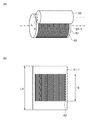
次に、トナー廃棄制御部102は、露光制御部47によって、一様に帯電された感光体ドラム51の表面に、トナー廃棄工程の露光パターンとなるように露光を行い、静電潜像を形成する。図6は、第1の実施の形態に関する画像形成装置のトナー廃棄工程の露光パターンの説明図である。なお、図6(a)が、露光パターン62の斜視図であり、図6(b)が感光体ドラム表面51−1の展開図である。 Next, the toner disposal control unit 102 exposes the surface of the uniformly charged photoconductor drum 51 by the exposure control unit 47 so as to have an exposure pattern in the toner disposal process, and forms an electrostatic latent image. To do. FIG. 6 is an explanatory diagram of an exposure pattern in the toner disposal step of the image forming apparatus according to the first embodiment. FIG. 6A is a perspective view of the exposure pattern 62, and FIG. 6B is a developed view of the photoconductor drum surface 51-1.

図6に示すように、トナー廃棄工程の露光パターン62は、例えば、感光体ドラム51の軸方向に1、0、1、0を繰り返す50%の静電潜像の露光パターンとする。露光パターン62は、長さが感光体ドラム51の周長Ldに対し、これより短い現像ローラ53の周長Lg分とし、感光体ドラム51の円周方向に平行な複数のラインからなるパターンである。この露光パターン62は、3色の画像形成ユニット11C、11M及び11Y全てにおいて同様とすればよい。第1の実施の形態では、この露光パターン62をドット数1,920ドットのラインが687本並んだものとしているが、異なるドット数及びライン数としてもよい。 As shown in FIG. 6, the exposure pattern 62 in the toner disposal step is, for example, an exposure pattern of a 50% electrostatic latent image that repeats 1, 0, 1, 0 in the axial direction of the photoconductor drum 51. The exposure pattern 62 is a pattern composed of a plurality of lines parallel to the circumferential direction of the photoconductor drum 51, with the length being equal to the peripheral length Lg of the developing roller 53 shorter than the peripheral length Ld of the photoconductor drum 51. is there. The exposure pattern 62 may be the same for all three color image forming units 11C, 11M and 11Y. In the first embodiment, the exposure pattern 62 is assumed to have 687 lines having 1,920 dots arranged side by side, but may have different numbers of dots and lines.

一方、トナー収納部61から供給ローラ54へと劣化した廃トナーTが供給される。供給ローラ54は回転しながら現像ローラ53に廃トナーTを供給する。現像ローラ53の表面に供給された劣化した廃トナーTは、現像ブレード55との間を通過する際に薄層化される。そして、現像ローラ53上の廃トナーT層が感光体ドラム51の上記図6に示す露光パターン62の静電潜像に付着する。 On the other hand, the deteriorated waste toner T is supplied from the toner storage unit 61 to the supply roller 54. The supply roller 54 supplies the waste toner T to the developing roller 53 while rotating. The deteriorated waste toner T supplied to the surface of the developing roller 53 is thinned as it passes between the developing roller 53 and the developing blade 55. Then, the waste toner T layer on the developing roller 53 adheres to the electrostatic latent image of the exposure pattern 62 shown in FIG. 6 of the photoconductor drum 51.

図7は第1の実施の形態に関する画像形成装置のトナー廃棄工程における転写電圧と廃トナーの関係を示す説明図である。図7(a)は第1の回収手段360の一部であるドラムクリーニングブレード56の作用を示し、図7(b)は第2の回収手段380の一部である転写ベルト19の作用を示す。 FIG. 7 is an explanatory diagram showing the relationship between the transfer voltage and the waste toner in the toner disposal step of the image forming apparatus according to the first embodiment. FIG. 7A shows the action of the drum cleaning blade 56 which is a part of the first recovery means 360, and FIG. 7B shows the action of the transfer belt 19 which is a part of the second recovery means 380. ..

図7(a)に示すように、トナー廃棄工程において第1の回収手段360による場合、トナー廃棄制御手段302は、転写ベルト19によるロール紙片2−1の搬送を行うことなく、かつ、転写ローラ63に転写電圧を印加しない。すると感光体ドラム51上に残留した廃トナーTは、転写ベルト19上に転写されずに感光体ドラム51上に残留する。感光体ドラム51上に残留した廃トナーTは、感光体ドラム51の矢印J方向への回転に従って、第1の回収手段360の一部であるドラムクリーニングブレード56によって取り除かれ、廃トナー一時貯留部57に一時貯留する。
その後は前述のように、廃トナー一時貯留部57内に一時貯留された廃トナーTは、スクリューコンベア58により、感光体ドラム51の軸方向としての装置側面側へ移動される。そして、廃トナーTは図示しない搬送手段により、図2に示すID廃トナー回収容器60に移動され、第1の廃トナーとして回収され貯蔵される。
As shown in FIG. 7A, when the first collecting means 360 is used in the toner disposal step, the toner disposal control means 302 does not carry the roll paper piece 2-1 by the transfer belt 19 and the transfer roller. No transfer voltage is applied to 63. Then, the waste toner T remaining on the photoconductor drum 51 is not transferred on the transfer belt 19 but remains on the photoconductor drum 51. The waste toner T remaining on the photoconductor drum 51 is removed by the drum cleaning blade 56, which is a part of the first recovery means 360, according to the rotation of the photoconductor drum 51 in the arrow J direction, and the waste toner temporary storage unit is used. Temporarily store in 57.
After that, as described above, the waste toner T temporarily stored in the waste toner temporary storage unit 57 is moved to the side surface side of the apparatus in the axial direction of the photoconductor drum 51 by the screw conveyor 58. Then, the waste toner T is moved to the ID waste toner collection container 60 shown in FIG. 2 by a transport means (not shown), and is collected and stored as the first waste toner.

一方、図7(b)に示すように、トナー廃棄工程において第2の回収手段380による場合、トナー廃棄制御手段302は、転写ベルト19によるロール紙片2−1の搬送を行わないが、感光体ドラム51上の廃トナーTを転写ベルト19に転写する転写動作を行う。このとき、転写ローラ63には、前述のようにトナー廃棄制御部102によって決定される転写電圧Vtrが印加される。
転写ベルト19上に転写された廃トナーTは、転写ベルト19の矢印D方向への周回に従って、図2に示すベルトクリーニングブレード81によって取り除かれ、ベルト廃トナーボックス80に移動され、第2の廃トナーとして回収され貯蔵される。
On the other hand, as shown in FIG. 7B, when the second recovery means 380 is used in the toner disposal step, the toner disposal control means 302 does not convey the roll paper piece 2-1 by the transfer belt 19, but the photoconductor. A transfer operation is performed to transfer the waste toner T on the drum 51 to the transfer belt 19. At this time, the transfer voltage Vtr determined by the toner disposal control unit 102 is applied to the transfer roller 63 as described above.
The waste toner T transferred onto the transfer belt 19 is removed by the belt cleaning blade 81 shown in FIG. 2 according to the circulation of the transfer belt 19 in the arrow D direction, moved to the belt waste toner box 80, and is moved to the second waste toner box 80. It is collected and stored as toner.

次に、第1の実施の形態に関する画像形成装置1のトナー廃棄工程における転写電圧Vtrの決定動作を更に詳細に説明する。前述のようにトナー廃棄工程における転写電圧Vtrは、制御部100の制御のもとにトナー廃棄制御手段302であるトナー廃棄制御部102が、感光体ドラム51の消耗度を表すドラムカウント値Dr及びトナー廃棄量を表すトナー廃棄カウント値Wtに基づいて決定される。
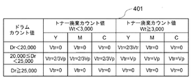
図8は、第1の実施の形態に関する画像形成装置のトナー廃棄工程における転写電圧Vtrの決定動作を示すフローチャート図である。また、図9は、第1の実施の形態に関する画像形成装置のトナー廃棄工程において決定される転写電圧Vtr決定表の説明図である。なお、転写電圧Vtr決定表401はROM部34に記憶される。
Next, the operation of determining the transfer voltage Vtr in the toner disposal step of the image forming apparatus 1 according to the first embodiment will be described in more detail. As described above, the transfer voltage Vtr in the toner disposal step is determined by the toner disposal control unit 102, which is the toner disposal control means 302, under the control of the control unit 100, and the drum count value Dr indicating the degree of wear of the photoconductor drum 51. It is determined based on the toner disposal count value Wt, which represents the amount of toner discarded.
FIG. 8 is a flowchart showing a determination operation of the transfer voltage Vtr in the toner disposal step of the image forming apparatus according to the first embodiment. Further, FIG. 9 is an explanatory diagram of a transfer voltage Vtr decision table determined in the toner disposal step of the image forming apparatus according to the first embodiment. The transfer voltage Vtr decision table 401 is stored in the ROM unit 34.

ステップS121:先ず、制御手段300のトナー廃棄制御手段302は、記憶部33のドラムカウント記憶部35aに記憶された感光体ドラム51の消耗度を表すドラムカウント値Dr及びトナー廃棄カウント記憶部35bに記憶されたこれまでに廃棄したトナー廃棄量を表すトナー廃棄カウント値Wtを読み出す。
ステップS122:次に、トナー廃棄制御手段302は、ドラムカウント値Drが感光体ドラム51の寿命の到来の基準となる第1の消耗度「25,000」以上であるか否かを判定する。第1の消耗度「25,000」以上であるときは画像形成ユニット11がドラム寿命に達していると判定しステップS123に移行する。
Step S121: First, the toner disposal control means 302 of the control means 300 tells the drum count value Dr and the toner disposal count storage unit 35b that represent the degree of wear of the photoconductor drum 51 stored in the drum count storage unit 35a of the storage unit 33. Read out the toner waste count value Wt that represents the stored toner waste amount that has been discarded so far.
Step S122: Next, the toner disposal control means 302 determines whether or not the drum count value Dr is equal to or greater than the first degree of wear "25,000", which is a reference for the arrival of the life of the photoconductor drum 51. When the first degree of wear is "25,000" or more, it is determined that the image forming unit 11 has reached the drum life, and the process proceeds to step S123.

ステップS123:トナー廃棄制御手段302は、図9に示す転写電圧Vtr決定表401のドラムカウント値Dr≧25,000の欄を参照し、3色の(全ての)画像形成ユニット11C、11M及び11Yの転写電圧Vtrを0Vに決定する。
転写電圧Vtr=0Vとすると、図7(a)に示したように廃トナーTは、転写ベルト19に転写されず、感光体ドラム51上に全て残留することになる。トナー廃棄制御手段302は、この残留した廃トナーTを後述するステップS131のトナー廃棄処理において、ドラムクリーニングブレード56で取り除き、第1の回収手段360であるID廃トナー回収容器60に第1の廃トナーとして回収することになる。
Step S123: The toner disposal control means 302 refers to the column of the drum count value Dr ≧ 25,000 in the transfer voltage Vtr determination table 401 shown in FIG. 9, and the three-color (all) image forming units 11C, 11M and 11Y. The transfer voltage Vtr of is determined to be 0V.
When the transfer voltage Vtr = 0V, as shown in FIG. 7A, the waste toner T is not transferred to the transfer belt 19 and remains entirely on the photoconductor drum 51. The toner disposal control means 302 removes the residual waste toner T with the drum cleaning blade 56 in the toner disposal process of step S131 described later, and first wastes the ID waste toner collection container 60 which is the first collection means 360. It will be collected as toner.

このようにドラム寿命となっているときは、印刷品質を保証できなくなるため、トナー廃棄制御手段302は、積極的に第1の回収手段360であるID廃トナー回収容器60に廃トナーTを回収する。そして、トナー廃棄制御手段302は、操作入力部12にドラム寿命による画像形成ユニット11の交換のメッセージを表示して操作者に報知する。また、このとき第2の回収手段380のベルト廃トナー回収容器80へは廃トナーTを回収しないようにするので、無駄にベルト廃トナー回収容器80が満杯になることが抑制される。即ち、トナー廃棄制御手段302は、感光体ドラム51の消耗度が第1の消耗度「25,000」以上のときは、廃トナーTを第1の回収手段360に第1の廃トナーとして全て回収するようにする(S123、S131)。 When the drum life is reached in this way, the print quality cannot be guaranteed. Therefore, the toner disposal control means 302 positively collects the waste toner T in the ID waste toner collection container 60, which is the first collection means 360. To do. Then, the toner disposal control means 302 displays a message of replacement of the image forming unit 11 due to the drum life on the operation input unit 12 to notify the operator. Further, at this time, since the waste toner T is not collected in the belt waste toner collection container 80 of the second collection means 380, it is possible to prevent the belt waste toner collection container 80 from being unnecessarily full. That is, when the degree of consumption of the photoconductor drum 51 is equal to or higher than the first degree of consumption "25,000", the toner disposal control means 302 uses all the waste toner T as the first waste toner in the first recovery means 360. It is to be collected (S123, S131).

ステップS124:一方、トナー廃棄制御手段302は、ステップS122においてドラムカウント値Drが画像形成ユニット11のドラム寿命に達していないと判定したときは、ドラムカウント値Drが第2の消耗度「20,000」以上であるか否かを判定する。ドラムカウント値Drが第2の消耗度「20,000」以上であるときは、画像形成ユニット11のドラム寿命の直前であると判定しステップS125に進む。即ち、ドラムカウント値Drの第2の消耗度「20,000」は、画像形成ユニット11がドラム寿命の到来の基準となる第1の消耗度「25,000」の直前であることを示す基準である。
ステップS125:ドラムカウント値Drが第2の消耗度「20,000」以上であるときは、トナー廃棄制御手段302は、トナー廃棄カウント値Wtがトナー廃棄量の多い状態であることを示す所定の廃棄量「3,000」以上であるか否かを判定する。トナー廃棄カウント値Wtが所定の廃棄量「3,000」以上のときは、ステップS126に進む。
Step S124: On the other hand, when the toner disposal control means 302 determines in step S122 that the drum count value Dr has not reached the drum life of the image forming unit 11, the drum count value Dr is the second consumption degree “20, It is determined whether or not it is "000" or more. When the drum count value Dr is the second degree of wear of "20,000" or more, it is determined that the image forming unit 11 is about to reach the end of the drum life, and the process proceeds to step S125. That is, the second degree of wear "20,000" of the drum count value Dr is a reference indicating that the image forming unit 11 is immediately before the first degree of wear "25,000" which is a reference for the arrival of the drum life. Is.
Step S125: When the drum count value Dr is the second degree of consumption "20,000" or more, the toner disposal control means 302 determines that the toner disposal count value Wt is in a state where the toner disposal amount is large. It is determined whether or not the amount of waste is "3,000" or more. When the toner disposal count value Wt is equal to or greater than the predetermined disposal amount “3,000”, the process proceeds to step S126.

ステップS126:ステップS125において、トナー廃棄カウント値Wtが所定の廃棄量「3,000」以上のときは、トナー廃棄制御手段302は、画像形成ユニット11がドラム寿命の直前でかつトナー廃棄量が多い状態であると判定する。そこで、トナー廃棄制御手段302は、図9に示す転写電圧Vtr決定表401の25,000>ドラムカウント値Dr≧20,000かつトナー廃棄カウント値Wt≧3,000の欄を参照する。そして、3色の(全ての)画像形成ユニット11C、11M及び11Yの転写電圧Vtrを印刷時の転写電圧Vpとする。 Step S126: In step S125, when the toner disposal count value Wt is the predetermined disposal amount “3,000” or more, the toner disposal control means 302 has the image forming unit 11 immediately before the drum life and the toner disposal amount is large. Determined to be in a state. Therefore, the toner disposal control means 302 refers to the columns of the transfer voltage Vtr determination table 401 shown in FIG. 9 where 25,000> drum count value Dr ≧ 20,000 and toner waste count value Wt ≧ 3,000. Then, the transfer voltage Vtr of the three-color (all) image forming units 11C, 11M and 11Y is set as the transfer voltage Vp at the time of printing.

転写電圧Vtr=Vpと設定された画像形成ユニット11は、図7(b)に示したように、印刷時の転写電圧Vpによって全ての廃トナーTを転写ベルト19に転写させることになる。そして、トナー廃棄制御手段302は、この転写ベルト19上に転写された廃トナーTを、ステップS131のトナー廃棄処理において、ベルトクリーニングブレード81によって取り除き、ベルト廃トナー回収容器80に第2の廃トナーとして回収することになる。 As shown in FIG. 7B, the image forming unit 11 in which the transfer voltage Vtr = Vp transfers all the waste toner T to the transfer belt 19 by the transfer voltage Vp at the time of printing. Then, the toner disposal control means 302 removes the waste toner T transferred onto the transfer belt 19 by the belt cleaning blade 81 in the toner disposal process in step S131, and puts the second waste toner in the belt waste toner collection container 80. Will be collected as.

このようにドラム寿命の直前であるときは、画像形成ユニット11自身のかぶりトナーが増加しトナー廃棄量が増加する。従って、トナー廃棄工程によってID廃トナー回収容器60に回収するトナー廃棄量を少なくする必要がある。このため、図7(b)に示すように転写電圧Vtr=Vpとして、ベルト廃トナー回収容器80により回収するトナー量を増加させ、これによりID廃トナー回収容器60が満杯になることを抑制する。
即ち、トナー廃棄制御手段302は、感光体ドラム51の消耗度がドラム寿命の基準となる第1の消耗度よりは少ないが、ドラム寿命の直前であることを示す第2の消耗度以上であって、かつトナー廃棄量が所定の廃棄量以上のときは、廃トナーTを第2の回収手段380に第2の廃トナーとして全て回収するようにする(S126、S131)。
As described above, when it is just before the drum life, the fog toner of the image forming unit 11 itself increases and the amount of toner discarded increases. Therefore, it is necessary to reduce the amount of toner discarded in the ID waste toner collection container 60 by the toner disposal step. Therefore, as shown in FIG. 7B, the transfer voltage Vtr = Vp is used to increase the amount of toner collected by the belt waste toner collection container 80, thereby suppressing the ID waste toner collection container 60 from becoming full. ..
That is, in the toner disposal control means 302, the degree of wear of the photoconductor drum 51 is less than the first degree of wear which is a reference of the drum life, but is equal to or higher than the second degree of wear indicating that it is just before the drum life. When the amount of toner discarded is equal to or greater than the predetermined amount of waste, all the waste toner T is collected by the second collecting means 380 as the second waste toner (S126, S131).

ステップS127:一方、:ステップS125において、トナー廃棄カウント値Wtが所定の廃棄量「3,000」未満のときは、トナー廃棄制御手段302は、画像形成ユニット11がドラム寿命の直前で、トナー廃棄量が少ない状態であると判定する。そこで、トナー廃棄制御手段302は、図9に示す転写電圧Vtr決定表401の25,000>ドラムカウント値Dr≧20,000かつトナー廃棄カウント値Wt<3,000の欄を参照する。そして3色の(全ての)画像形成ユニット11C、11M及び11Yの転写電圧Vtrを印刷時の転写電圧Vpより低い2/3Vpとする。 Step S127: On the other hand: In step S125, when the toner disposal count value Wt is less than the predetermined disposal amount "3,000", the toner disposal control means 302 discards the toner immediately before the image forming unit 11 has reached the end of the drum life. It is determined that the amount is small. Therefore, the toner disposal control means 302 refers to the columns of the transfer voltage Vtr determination table 401 shown in FIG. 9 in which 25,000> drum count value Dr ≧ 20,000 and the toner disposal count value Wt <3,000. Then, the transfer voltage Vtr of the three-color (all) image forming units 11C, 11M and 11Y is set to 2/3 Vp, which is lower than the transfer voltage Vp at the time of printing.

転写電圧Vtr=2/3Vpと設定された画像形成ユニット11は、転写電圧Vtr=2/3Vpの電圧によって廃トナーTを転写ベルト19に転写させることになる。そして、ステップS131のトナー廃棄処理において、ベルトクリーニングブレード81によって転写ベルト19上の廃トナーTを取り除き、ベルト廃トナー回収容器80に第2の廃トナーとして回収することになる。このとき、転写電圧Vtrは、印刷時の転写電圧Vpより低い2/3Vpであるため、転写ベルト19に転写されずに感光体ドラム51に残留する廃トナーTが生じる。この廃トナーTは、ドラムクリーニングブレード56で取り除かれて画像形成ユニット11側のID廃トナー回収容器60に第1の廃トナーとして回収されることになる。 The image forming unit 11 in which the transfer voltage Vtr = 2/3 Vp is set to transfer the waste toner T to the transfer belt 19 by the voltage of the transfer voltage Vtr = 2/3 Vp. Then, in the toner disposal process of step S131, the waste toner T on the transfer belt 19 is removed by the belt cleaning blade 81, and the waste toner T is collected as the second waste toner in the belt waste toner collection container 80. At this time, since the transfer voltage Vtr is 2/3 Vp, which is lower than the transfer voltage Vp at the time of printing, waste toner T that remains on the photoconductor drum 51 without being transferred to the transfer belt 19 is generated. The waste toner T is removed by the drum cleaning blade 56 and collected as the first waste toner in the ID waste toner collection container 60 on the image forming unit 11 side.

即ち、トナー廃棄制御手段302は、感光体ドラム51の消耗度が第1の消耗度未満であるが、第2の消耗度以上であって、トナー廃棄量が所定の廃棄量より少ない状態であるときは、廃トナーTを第1の回収手段360に第1の廃トナーとして回収し、そして第2の回収手段380に第2の廃トナーとして同時に分けて回収するようにする(S127、S131)。 That is, in the toner disposal control means 302, the degree of consumption of the photoconductor drum 51 is less than the first degree of consumption, but is equal to or higher than the second degree of consumption, and the amount of toner discarded is less than the predetermined amount of waste. At this time, the waste toner T is collected by the first collection means 360 as the first waste toner, and is simultaneously collected by the second collection means 380 as the second waste toner (S127, S131). ..

ステップS128:一方、ステップS124においてドラムカウント値Dr<20,000であり、画像形成ユニット11のドラム寿命の直前でもない状態であるときは、トナー廃棄制御手段302は、トナー廃棄カウント値Wtがトナー廃棄量の多い状態であることを示す所定の廃棄量「3,000」以上であるか否かを判定する。トナー廃棄カウント値Wtが所定の廃棄量「3,000」以上のときは、ステップS129に進む。
ステップS129:トナー廃棄制御手段302は、画像形成ユニット11のドラム寿命の直前でもなく、トナー廃棄量が多い状態であるときは、図9に示す転写電圧Vtr決定表401のドラムカウント値Dr<20,000かつトナー廃棄カウント値Wt≧3,000の欄を参照する。そして、搬送最下流の画像形成ユニット11Yの転写電圧Vtrのみを2/3Vpとし、画像形成ユニット11M及び11Cの転写電圧Vtrを0Vとする。
Step S128: On the other hand, when the drum count value Dr <20,000 in step S124 and it is not immediately before the drum life of the image forming unit 11, the toner disposal control means 302 has a toner disposal count value Wt of toner. It is determined whether or not the amount of waste is "3,000" or more, which indicates that the amount of waste is large. When the toner disposal count value Wt is equal to or greater than the predetermined disposal amount “3,000”, the process proceeds to step S129.
Step S129: When the toner disposal control means 302 is not immediately before the drum life of the image forming unit 11 and the toner disposal amount is large, the drum count value Dr <20 in the transfer voltage Vtr determination table 401 shown in FIG. Refer to the column of 000 and toner disposal count value Wt ≧ 3,000. Then, only the transfer voltage Vtr of the image forming unit 11Y at the most downstream of the transfer is set to 2/3 Vp, and the transfer voltage Vtr of the image forming units 11M and 11C is set to 0V.

転写電圧Vtrが2/3Vpと設定された画像形成ユニット11Yは、ロール紙片2−1の矢印Dで示す搬送方向における搬送最下流の位置である。画像形成ユニット11Yは、転写電圧Vtr=2/3Vpの電圧によって転写ベルト19に廃トナーTを転写させることになる。そして、ステップS131のトナー廃棄処理において、ベルトクリーニングブレード81によって転写ベルト19上の廃トナーTを取り除いて、ベルト廃トナー回収容器80に第2の廃トナーとして回収することになる。このとき、画像形成ユニット11Yの転写電圧Vtrは印刷時の転写電圧Vpより低い2/3Vpであるため、転写ベルト19に転写されずに感光体ドラム51に残った廃トナーTが生じる。この廃トナーTは、ドラムクリーニングブレード56で取り除かれ、画像形成ユニット11側のID廃トナー回収容器60に第1の廃トナーとして回収されることになる。 The image forming unit 11Y in which the transfer voltage Vtr is set to 2/3 Vp is the most downstream position of the transfer in the transfer direction indicated by the arrow D of the roll paper piece 2-1. The image forming unit 11Y transfers the waste toner T to the transfer belt 19 by a voltage of the transfer voltage Vtr = 2/3 Vp. Then, in the toner disposal process in step S131, the waste toner T on the transfer belt 19 is removed by the belt cleaning blade 81, and the waste toner T is collected as the second waste toner in the belt waste toner collection container 80. At this time, since the transfer voltage Vtr of the image forming unit 11Y is 2/3 Vp, which is lower than the transfer voltage Vp at the time of printing, waste toner T remaining on the photoconductor drum 51 without being transferred to the transfer belt 19 is generated. The waste toner T is removed by the drum cleaning blade 56, and is collected as the first waste toner in the ID waste toner collection container 60 on the image forming unit 11 side.

このように、画像形成ユニット11がドラム寿命の直前でなく、トナー廃棄量が多い状態であるときは、ID廃トナー回収容器60のみに回収し続けるとID廃トナー回収容器60の容量に余裕がなくなる。特に、画像形成ユニット11Yは搬送最下流に位置しているため、搬送上流側の画像形成ユニット11M、11Cのトナーが逆転写によって画像形成ユニット11Yの感光体ドラム51に廃トナーTが移り、画像形成ユニット11Yの廃トナーTが増える。このため、搬送最下流の位置にある画像形成ユニット11Yのみ転写電圧Vtrを2/3Vpとし、ベルト廃トナー回収容器80にも廃棄トナーを回収するようにする。 As described above, when the image forming unit 11 is not immediately before the drum life and the amount of toner discarded is large, if the image forming unit 11 is continuously collected only in the ID waste toner collecting container 60, the capacity of the ID waste toner collecting container 60 has a margin. It disappears. In particular, since the image forming unit 11Y is located at the most downstream side of the transfer, the toners of the image forming units 11M and 11C on the upstream side of the transfer are transferred back to the photoconductor drum 51 of the image forming unit 11Y, and the waste toner T is transferred to the image. The amount of waste toner T in the forming unit 11Y increases. Therefore, the transfer voltage Vtr is set to 2/3 Vp only for the image forming unit 11Y located at the most downstream position of the transfer, and the waste toner is also collected in the belt waste toner collection container 80.

即ち、トナー廃棄制御手段302は、感光体ドラム51の消耗度が第2の消耗度未満の場合であって、トナー廃棄量が所定の廃棄量以上のときは、一部の画像形成ユニット11のみが第1の回収手段360に第1の廃トナーとして回収し、かつ第2の回収手段380に第2の廃トナーとして同時に分けて回収する。そして、他の画像形成ユニット11は第1の回収手段360に第1の廃トナーとして全て回収するようにする(S129、S131)。 That is, the toner disposal control means 302 is only a part of the image forming unit 11 when the degree of wear of the photoconductor drum 51 is less than the second degree of wear and the amount of toner waste is equal to or more than the predetermined amount of waste. Collects the waste toner as the first waste toner in the first collection means 360, and simultaneously separates and collects the waste toner as the second waste toner in the second collection means 380. Then, the other image forming unit 11 collects all of the waste toner as the first waste toner in the first collecting means 360 (S129, S131).

ステップS130:一方、画像形成ユニット11がドラム寿命の直前ではなく、かつトナー廃棄量が少ない状態であるときは、トナー廃棄制御手段302は、図9に示す転写電圧Vtr決定表401のドラムカウント値Dr<20,000かつトナー廃棄カウント値Wt<3,000の欄を参照する。そして、3色の(全ての)画像形成ユニット11C、11M及び11Yの転写電圧Vtrを0Vとする。この設定により、転写ベルト19には廃トナーTが転写されず、感光体ドラム51上に廃トナーTが残留することになる。そして、ステップS131のトナー廃棄処理において、全ての廃トナーTがドラムクリーニングブレード56によって取り除かれてID廃トナー回収容器60に第1の廃トナーとして回収されることになる。 Step S130: On the other hand, when the image forming unit 11 is not immediately before the drum life and the amount of toner discarded is small, the toner disposal control means 302 uses the drum count value of the transfer voltage Vtr determination table 401 shown in FIG. Refer to the columns of Dr <20,000 and toner waste count value Wt <3,000. Then, the transfer voltage Vtr of the three-color (all) image forming units 11C, 11M and 11Y is set to 0V. With this setting, the waste toner T is not transferred to the transfer belt 19, and the waste toner T remains on the photoconductor drum 51. Then, in the toner disposal process of step S131, all the waste toner T is removed by the drum cleaning blade 56 and collected as the first waste toner in the ID waste toner collection container 60.

このように、画像形成ユニット11のドラム寿命の直前ではなく、かつトナー廃棄量が少ない状態のときは、ID廃トナー回収容器60の容量に十分な余裕があるため満杯になるおそれはなく、全ての廃トナーTをID廃トナー回収容器60に回収するようにする。
即ち、トナー廃棄制御手段302は、像担持体の消耗度が第2の消耗度未満の場合であって、トナー廃棄量が所定の廃棄量未満のときは、全て第1の回収手段360に第1の廃トナーとして回収するようにする(S130、S131)。
As described above, when the toner waste amount is small and not immediately before the drum life of the image forming unit 11, there is a sufficient capacity of the ID waste toner collection container 60, so that there is no possibility that the container will become full. Waste toner T is collected in the ID waste toner collection container 60.
That is, when the degree of wear of the image carrier is less than the second degree of wear and the amount of toner waste is less than the predetermined amount of waste, the toner waste control means 302 is all used by the first recovery means 360. It is collected as the waste toner of 1 (S130, S131).

ステップS131:トナー廃棄制御手段302は、以上のように決定された転写電圧Vtrによってトナー廃棄処理を行い、廃トナーTをID廃トナー回収容器60及びベルト廃トナー回収容器80に分けて回収する。
トナー廃棄処理は、感光体ドラム51上の廃トナーTをドラムクリーニングブレード56によって取り除いて、ID廃トナー回収容器60に第1の廃トナーとして回収する。また、転写ベルト19に転写された廃トナーTをベルトクリーニングブレード81によって取り除いて、ベルト廃トナー回収容器80に第2の廃トナーとして回収する。
Step S131: The toner disposal control means 302 performs the toner disposal process by the transfer voltage Vtr determined as described above, and collects the waste toner T separately into the ID waste toner collection container 60 and the belt waste toner collection container 80.
In the toner disposal treatment, the waste toner T on the photoconductor drum 51 is removed by the drum cleaning blade 56 and collected as the first waste toner in the ID waste toner collection container 60. Further, the waste toner T transferred to the transfer belt 19 is removed by the belt cleaning blade 81 and collected as the second waste toner in the belt waste toner collection container 80.

なお、以上の第1の実施の形態に関する画像形成装置1の説明では、ドラムカウント値Dr及びトナー廃棄カウント値Wtに基づいて、転写電圧Vtrを、0V、2/3Vp、Vpの3段階に変化させるように説明したが、更に4段階以上に細分化して変化させるようにしてもよい。
又、以上の第1の実施の形態に関する画像形成装置1の説明では、ドラムカウント値Dr及びトナー廃棄カウント値Wtに基づいて、転写電圧Vtrを変化させるように説明したが、ドラムカウント値Drのみによって変化させるようにしてもよいし、トナー廃棄カウント値Wtのみによって変化させるようにしてもよい。
In the description of the image forming apparatus 1 according to the first embodiment, the transfer voltage Vtr is changed to three stages of 0V, 2 / 3Vp, and Vp based on the drum count value Dr and the toner disposal count value Wt. Although it has been explained so as to be performed, it may be further subdivided into four or more stages and changed.
Further, in the description of the image forming apparatus 1 according to the first embodiment described above, it has been described that the transfer voltage Vtr is changed based on the drum count value Dr and the toner waste count value Wt, but only the drum count value Dr. It may be changed by only the toner waste count value Wt.

次に、トナー廃棄工程における廃トナー回収容器に回収されたトナー廃棄量の測定結果について、第1の実施の形態に関する画像形成装置1による場合と、図示しない比較例による場合を説明する。比較例では、装置の構成は第1の実施の形態に関する画像形成装置1と同じであるが、転写電圧Vtrを変化させていない。一方、第1の実施の形態に関する画像形成装置1では、前述のように転写電圧Vtrをドラムカウント値Dr及びトナー廃棄カウント値Wtに基づいて変化させている。 Next, the measurement result of the amount of toner discarded in the waste toner collection container in the toner disposal step will be described with respect to the case of the image forming apparatus 1 according to the first embodiment and the case of a comparative example (not shown). In the comparative example, the configuration of the device is the same as that of the image forming device 1 according to the first embodiment, but the transfer voltage Vtr is not changed. On the other hand, in the image forming apparatus 1 according to the first embodiment, the transfer voltage Vtr is changed based on the drum count value Dr and the toner disposal count value Wt as described above.

図10は、各廃トナー回収容器に回収された廃トナー重量測定結果の説明図である。図10(a)が比較例により回収された廃トナーTの重量測定結果であり、図10(b)が第1の実施の形態に関する画像形成装置1により回収された廃トナーTの重量測定結果である。なお、本測定において用いたトナーは、ポリエステル樹脂、着色剤、帯電制御剤及び離型剤を成分とし、外添剤として疎水シリカを添加し、粉砕法により得られた粉砕形状の平均粒径7μmの現像剤とした。 FIG. 10 is an explanatory diagram of the weight measurement result of the waste toner collected in each waste toner collection container. FIG. 10A shows the weight measurement result of the waste toner T recovered by the comparative example, and FIG. 10B shows the weight measurement result of the waste toner T recovered by the image forming apparatus 1 according to the first embodiment. Is. The toner used in this measurement contains a polyester resin, a colorant, a charge control agent, and a mold release agent as components, and hydrophobic silica is added as an external additive, and the average particle size of the pulverized shape obtained by the pulverization method is 7 μm. Was used as the developer.

測定方法は、印刷パターンを0%dutyとし、何も印刷せずにドラムカウント値Dr=25,000カウントまで印刷工程を実施し、その間に発生したトナー廃棄工程によってID廃トナー回収容器60及びベルト廃トナー回収容器80に廃棄トナーとして回収された廃トナーTの重量を測定した。0%dutyでの印刷では、最もトナー廃棄回数が多くなり、かつ、かぶりトナーによるトナー消費が最も多くなる条件であるので、この最も厳しい条件でトナー廃棄量の測定を行った。 In the measurement method, the printing pattern is set to 0% duty, the printing process is carried out up to the drum count value Dr = 25,000 counts without printing anything, and the ID waste toner collection container 60 and the belt are subjected to the toner disposal process generated during that period. The weight of the waste toner T collected as the waste toner in the waste toner collection container 80 was measured. In printing at 0% duty, the number of times of toner disposal is the largest and the toner consumption by the fog toner is the largest. Therefore, the toner disposal amount was measured under these strictest conditions.

比較例による測定では、ドラムカウント値Dr及びトナー廃棄カウント値Wtによって転写電圧Vtrを変化させず、転写電圧Vtr=0Vとした。その結果、図10(a)に示すように、ベルト廃トナー回収容器80には廃棄されず、ID廃トナー回収容器60だけに廃トナーTが回収された。即ち、ドラムカウント値Dr及びトナー廃棄カウント値Wtがいずれの場合においても、ベルト廃トナー回収容器80に回収された廃トナー重量は0.00gであった。その結果、ベルト廃トナー回収容器80の総廃トナー重量も0.00gであった。 In the measurement according to the comparative example, the transfer voltage Vtr was not changed by the drum count value Dr and the toner disposal count value Wt, and the transfer voltage Vtr was set to 0V. As a result, as shown in FIG. 10A, the waste toner T was not discarded in the belt waste toner collection container 80, but was collected only in the ID waste toner collection container 60. That is, in either case of the drum count value Dr and the toner waste count value Wt, the weight of the waste toner collected in the belt waste toner collection container 80 was 0.00 g. As a result, the total waste toner weight of the belt waste toner recovery container 80 was also 0.00 g.

一方、ID廃トナー回収容器60においては、トナー廃棄量が少ないトナー廃棄カウント値Wt<3,000の場合では、次のような測定結果となった。即ち、感光体ドラム51の消耗度が低いドラムカウント値Dr<20,000では、画像形成ユニット11YのID廃トナー回収容器60には、9.53gが回収された。また、感光体ドラム51の消耗が進み、20,000≦ドラムカウント値Dr<25,000では、2.38gが回収された。更に、感光体ドラム51がドラム寿命に達したドラムカウント値Dr≧25,000では、2.38gが回収された。同様に画像形成ユニット11M及び画像形成ユニット11Cについては図10(a)に示す通りの廃トナー重量の廃トナーTが回収された。 On the other hand, in the ID waste toner collection container 60, when the toner waste count value Wt <3,000, which has a small amount of toner waste, the following measurement results were obtained. That is, at a drum count value Dr <20,000, which has a low degree of wear of the photoconductor drum 51, 9.53 g was recovered in the ID waste toner recovery container 60 of the image forming unit 11Y. Further, the photoconductor drum 51 was consumed, and when 20,000 ≦ drum count value Dr <25,000, 2.38 g was recovered. Further, when the drum count value Dr ≧ 25,000 when the photoconductor drum 51 reached the drum life, 2.38 g was recovered. Similarly, for the image forming unit 11M and the image forming unit 11C, the waste toner T having the weight of the waste toner as shown in FIG. 10A was recovered.

また、トナー廃棄量が多いトナー廃棄カウント値Wt≧3,000の場合では、次のような測定結果となった。即ち、ドラムカウント値Dr<20,000では、画像形成ユニット11YのID廃トナー回収容器60には、10.45gが回収された。また、20,000≦ドラムカウント値Dr<25,000では、2.61gが回収された。更に、ドラムカウント値Dr≧25,000では、2.61gが回収された。同様に画像形成ユニット11M及び画像形成ユニット11Cについては図10(a)に示す通りの廃トナー重量の廃トナーTが回収された。 Further, when the toner waste count value Wt ≧ 3,000, which has a large amount of toner waste, the following measurement results were obtained. That is, when the drum count value Dr <20,000, 10.45 g was recovered in the ID waste toner recovery container 60 of the image forming unit 11Y. Further, when 20,000 ≦ drum count value Dr <25,000, 2.61 g was recovered. Further, when the drum count value Dr ≧ 25,000, 2.61 g was recovered. Similarly, for the image forming unit 11M and the image forming unit 11C, the waste toner T having the weight of the waste toner as shown in FIG. 10A was recovered.

この場合の総廃トナー重量は、それぞれのトナー廃棄カウント値Wt及びドラムカウント値Drにおける廃トナー重量の合計である。画像形成ユニット11YのID廃トナー回収容器60では、前述の9.53g、2.38g、2.38g、10.45g、2.61g及び2.61gの合計である29.97gが総廃トナー重量となった。同様に、画像形成ユニット11M及び画像形成ユニット11Cにおいては、ID廃トナー回収容器60に回収された総廃トナー重量は40.54g及び35.52gとなった。 The total waste toner weight in this case is the total of the waste toner weights at the respective toner waste count value Wt and drum count value Dr. In the ID waste toner recovery container 60 of the image forming unit 11Y, 29.97 g, which is the total of 9.53 g, 2.38 g, 2.38 g, 10.45 g, 2.61 g and 2.61 g described above, is the total waste toner weight. It became. Similarly, in the image forming unit 11M and the image forming unit 11C, the total weight of the waste toner collected in the ID waste toner collecting container 60 was 40.54 g and 35.52 g.

一方、第1の実施の形態に関する画像形成装置1による測定では、図9に示すようにドラムカウント値Dr及びトナー廃棄カウント値Wtに基づいて転写電圧Vtrを変化させた。その結果、図10(b)に示すように、ID廃トナー回収容器60及びベルト廃トナー回収容器80に分けて廃トナーTが回収された。
先ず、ID廃トナー回収容器60においては、トナー廃棄カウント値Wt<3,000の場合では、次のような測定結果となった。即ち、ドラムカウント値Dr<20,000では、画像形成ユニット11YのID廃トナー回収容器60には、9.53gが回収された。また、20,000≦ドラムカウント値Dr<25,000では、0.79gが回収された。更に、ドラムカウント値Dr≧25,000では、2.38gが回収された。同様に画像形成ユニット11M及び画像形成ユニット11Cについては図10(b)に示す通りの廃トナー重量の廃トナーTが回収された。
On the other hand, in the measurement by the image forming apparatus 1 according to the first embodiment, as shown in FIG. 9, the transfer voltage Vtr was changed based on the drum count value Dr and the toner waste count value Wt. As a result, as shown in FIG. 10B, the waste toner T was collected separately in the ID waste toner collection container 60 and the belt waste toner collection container 80.
First, in the ID waste toner collection container 60, when the toner waste count value Wt <3,000, the following measurement results were obtained. That is, when the drum count value Dr <20,000, 9.53 g was collected in the ID waste toner collection container 60 of the image forming unit 11Y. Further, when 20,000 ≦ drum count value Dr <25,000, 0.79 g was recovered. Further, when the drum count value Dr ≧ 25,000, 2.38 g was recovered. Similarly, for the image forming unit 11M and the image forming unit 11C, the waste toner T having the weight of the waste toner as shown in FIG. 10B was recovered.

また、トナー廃棄カウント値Wt≧3,000の場合では、次のような測定結果となった。即ち、ドラムカウント値Dr<20,000では、画像形成ユニット11YのID廃トナー回収容器60には、3.48gが回収された。また、20,000≦ドラムカウント値Dr<25,000では、0.00gが回収された。更に、ドラムカウント値Dr≧25,000では、2.61gが回収された。同様に画像形成ユニット11M及び画像形成ユニット11Cについては図10(b)に示す通りの廃トナー重量の廃トナーTが回収された。 Further, when the toner waste count value Wt ≧ 3,000, the following measurement results were obtained. That is, when the drum count value Dr <20,000, 3.48 g was collected in the ID waste toner collection container 60 of the image forming unit 11Y. Further, when 20,000 ≦ drum count value Dr <25,000, 0.00 g was recovered. Further, when the drum count value Dr ≧ 25,000, 2.61 g was recovered. Similarly, for the image forming unit 11M and the image forming unit 11C, the waste toner T having the weight of the waste toner as shown in FIG. 10B was recovered.

この場合の総廃トナー重量は、画像形成ユニット11YのID廃トナー回収容器60では、それぞれのトナー廃棄カウント値Wt及びドラムカウント値Drにおける廃トナー重量の合計である。即ち、前述の9.53g、0.79g、2.38g、3.48g、0.00g及び2.61gの合計である18.81gが総廃トナー重量となった。同様に、図10(b)に示すように、画像形成ユニット11M及び画像形成ユニット11Cにおいて、ID廃トナー回収容器60に回収された総廃トナー重量は、34.86g及び30.54gであった。 The total waste toner weight in this case is the total of the waste toner weights at the respective toner waste count value Wt and drum count value Dr in the ID waste toner recovery container 60 of the image forming unit 11Y. That is, 18.81 g, which is the total of the above-mentioned 9.53 g, 0.79 g, 2.38 g, 3.48 g, 0.00 g and 2.61 g, was the total waste toner weight. Similarly, as shown in FIG. 10B, in the image forming unit 11M and the image forming unit 11C, the total waste toner weights collected in the ID waste toner collecting container 60 were 34.86 g and 30.54 g. ..

一方、ベルト廃トナー回収容器80において、トナー廃棄カウント値Wt<3,000の場合では、次のような測定結果となった。即ち、ドラムカウント値Dr<20,000では、画像形成ユニット11Yのベルト廃トナー回収容器80には0.00gが回収された。更に、20,000≦ドラムカウント値Dr<25,000では、1.59gが回収された。更に、ドラムカウント値Dr≧25,000では、0.00gが回収された。 On the other hand, in the belt waste toner collection container 80, when the toner waste count value Wt <3,000, the following measurement results were obtained. That is, when the drum count value Dr <20,000, 0.00 g was recovered in the belt waste toner recovery container 80 of the image forming unit 11Y. Further, when 20,000 ≦ drum count value Dr <25,000, 1.59 g was recovered. Further, when the drum count value Dr ≧ 25,000, 0.00 g was recovered.

また、トナー廃棄カウント値Wt≧3,000場合では、次のような測定結果となった。即ち、ドラムカウント値Dr<20,000では、画像形成ユニット11Yのベルト廃トナー回収容器80には、6.97gが回収された。また、20,000≦ドラムカウント値Dr<25,000では、2.61gが回収された。更に、ドラムカウント値Dr≧25,000では、0.00gが回収された。同様に画像形成ユニット11M及び画像形成ユニット11Cについては図10(b)に示す通りの廃トナー重量の廃トナーTが回収された。
ベルト廃トナー回収容器80の総廃トナー重量は、3色のトナーY、M及びCについてそれぞれのトナー廃棄カウント値Wt及びドラムカウント値Drにおける廃トナー重量の合計である。即ち、21.83gが総廃トナー重量となった。
Further, when the toner waste count value Wt ≧ 3,000, the following measurement results were obtained. That is, when the drum count value Dr <20,000, 6.97 g was collected in the belt waste toner collection container 80 of the image forming unit 11Y. Further, when 20,000 ≦ drum count value Dr <25,000, 2.61 g was recovered. Further, when the drum count value Dr ≧ 25,000, 0.00 g was recovered. Similarly, for the image forming unit 11M and the image forming unit 11C, the waste toner T having the weight of the waste toner as shown in FIG. 10B was recovered.
The total waste toner weight of the belt waste toner collection container 80 is the total of the waste toner weights at the toner waste count value Wt and the drum count value Dr for each of the three color toners Y, M and C. That is, 21.83 g was the total waste toner weight.

以上の図10に示す測定結果に基づいて評価判定を行った。図11は、図10に示す廃トナー重量測定結果に基づく評価結果の説明図である。図11(a)が比較例による測定結果に基づく評価結果であり、図11(b)が第1の実施の形態による測定結果に基づく評価結果である。
評価判定は、ID廃トナー回収容器60及びベルト廃トナー回収容器80に回収された総廃トナー重量に関して以下のように行う。即ち、ID廃トナー回収容器60については、回収された総廃トナー重量が、充填可能な最大重量41.6gに対して85%である35.4gより少ない場合は、容器が満杯になるおそれはないので、良好(○)と判定する。一方、回収された総廃トナー重量が、35.4g以上の場合は、容器が満杯になるおそれがあるので、不良(×)と判定する。
The evaluation judgment was made based on the measurement results shown in FIG. FIG. 11 is an explanatory diagram of an evaluation result based on the waste toner weight measurement result shown in FIG. FIG. 11A is an evaluation result based on the measurement result according to the comparative example, and FIG. 11B is an evaluation result based on the measurement result according to the first embodiment.
The evaluation determination is performed as follows with respect to the total waste toner weight collected in the ID waste toner collection container 60 and the belt waste toner collection container 80. That is, with respect to the ID waste toner recovery container 60, if the total weight of the recovered waste toner is less than 35.4 g, which is 85% of the maximum refillable weight of 41.6 g, the container may become full. Since there is no such thing, it is judged to be good (○). On the other hand, if the total weight of the recovered waste toner is 35.4 g or more, the container may become full, so it is determined to be defective (x).

また、ベルト廃トナー回収容器80については、回収された総廃トナー重量が、充填可能な最大重量154.7gに対して85%である131.5gより少ない場合は、容器が満杯になるおそれはないので、良好(○)と判定する。一方、回収された総廃トナー重量が131.5g以上の場合は、容器が満杯になるおそれがあるので、不良(×)と判定する。
その結果、比較例では、図11(a)に示すように、画像形成ユニット11M及び11CのID廃トナー回収容器60が不良(×)の判定となった。この場合、ドラム寿命となるまでにID廃トナー回収容器60の方が先に満杯となり交換が必要となるおそれがある。従って、総合判定結果は不良(×)の判定となった。
Further, regarding the belt waste toner recovery container 80, if the total weight of the recovered waste toner is less than 131.5 g, which is 85% of the maximum refillable weight of 154.7 g, the container may become full. Since there is no such thing, it is judged to be good (○). On the other hand, if the total weight of the recovered waste toner is 131.5 g or more, the container may become full, so it is determined to be defective (x).
As a result, in the comparative example, as shown in FIG. 11A, the ID waste toner recovery container 60 of the image forming units 11M and 11C was determined to be defective (x). In this case, the ID waste toner collection container 60 may become full earlier and need to be replaced before the end of the drum life. Therefore, the overall judgment result was a defect (x) judgment.

一方、図11(b)に示すように、本発明の第1の実施の形態では、いずれの画像形成ユニット11のID廃トナー回収容器60も良好(○)の判定であった。また、ベルト廃トナー回収容器80についても全て良好(○)の判定であった。また、ドラムカウント値Dr=100K時点においても、ベルト廃トナー回収容器80には87.31gが回収され、充填可能な最大重量154.7gに対して85%である131.5gよりも少なかった。従って、第1の実施の形態に関する画像形成装置1では、ドラム寿命までにいずれの回収容器も満杯になるおそれはなく、総合判定は良好(○)の判定となった。 On the other hand, as shown in FIG. 11B, in the first embodiment of the present invention, the ID waste toner recovery container 60 of any of the image forming units 11 was judged to be good (◯). In addition, the belt waste toner recovery container 80 was also judged to be good (◯). Further, even at the time of the drum count value Dr = 100K, 87.31 g was recovered in the belt waste toner recovery container 80, which was less than 131.5 g, which was 85% of the maximum fillable weight of 154.7 g. Therefore, in the image forming apparatus 1 according to the first embodiment, there is no possibility that any of the collection containers will be full by the end of the drum life, and the overall judgment is good (◯).

このように第1の実施の形態に関する画像形成装置1では、トナー廃棄工程における転写電圧Vtrを図9に示すようにIDドラムカウント値Dr及び廃棄トナーカウントWtに応じて変化させるようにした。その結果、ドラム寿命までID廃トナー回収容器60及びベルト廃トナー回収容器80のいずれも満杯になるおそれがないことが確認された。即ち、第1の実施の形態に関する画像形成装置1によれば、ドラム寿命まで画像形成ユニット11を交換することなく使用できることができることが確認された。
また、特に、搬送上流側の画像形成ユニット11M、11Cからの逆転写による廃トナーTが増加する搬送最下流の画像形成ユニット11Yにおいても、ドラム寿命までID廃トナー回収容器60が満杯になるおそれはなく、更に容量に余裕を持たせることができることも確認された。
As described above, in the image forming apparatus 1 according to the first embodiment, the transfer voltage Vtr in the toner disposal step is changed according to the ID drum count value Dr and the discarded toner count Wt as shown in FIG. As a result, it was confirmed that neither the ID waste toner recovery container 60 nor the belt waste toner recovery container 80 is likely to become full until the drum life. That is, according to the image forming apparatus 1 according to the first embodiment, it was confirmed that the image forming unit 11 can be used until the drum life without replacement.
Further, in particular, even in the image forming unit 11Y at the most downstream side of the transport where the waste toner T due to reverse transfer from the image forming units 11M and 11C on the upstream side of the transport increases, the ID waste toner collection container 60 is full until the drum life. It was also confirmed that there was no such thing and that the capacity could be further increased.

以上のように、第1の実施の形態に関する画像形成装置1によれば、現像剤廃棄制御手段302は、転写電圧Vtrを変化させて廃トナーTを第1の回収手段360及び第2の回収手段380に分けて回収するよう制御するので、効率よく廃トナーTを回収でき、その結果、画像形成ユニット11の交換時期を長くすることができる。 As described above, according to the image forming apparatus 1 according to the first embodiment, the developer disposal control means 302 changes the transfer voltage Vtr to collect the waste toner T in the first recovery means 360 and the second recovery means 360. Since the means is controlled to be divided into 380 and collected, the waste toner T can be efficiently collected, and as a result, the replacement period of the image forming unit 11 can be lengthened.

以上の実施の形態に関する画像形成装置1の説明では、Y(イエロー)、M(マゼンダ)及びC(シアン)の3色の画像形成ユニット11を備えた画像形成装置1を例として説明したが、更にK(クロ)トナーを追加した4色の画像形成ユニット11を備えた画像形成装置1にも本発明を適用できる。また、更にW(ホワイト)、CL(透明)を追加した5色又は6色の画像形成ユニット11を備えた画像形成装置1にも本発明を適用することができる。 In the description of the image forming apparatus 1 according to the above embodiment, the image forming apparatus 1 provided with the image forming unit 11 of three colors of Y (yellow), M (magenta), and C (cyan) has been described as an example. Further, the present invention can be applied to an image forming apparatus 1 provided with a four-color image forming unit 11 to which K (black) toner is added. Further, the present invention can also be applied to an image forming apparatus 1 provided with an image forming unit 11 having five or six colors to which W (white) and CL (transparent) are added.

また、以上の実施の形態に関する画像形成装置1の説明では、ロール紙片2−1に直接転写する画像形成装置1を例として説明したが、転写ベルト19を介してロール紙片2−1に転写する中間転写型の画像形成装置1にも本発明を適用することができる。
また、以上の実施の形態に関する画像形成装置1の説明では、ロール紙を用いたプリンタを例として説明したが、普通用紙を用いたプリンタ、複写機、LEDブリンタ、レーザービームプリンク、ファクシミリ装置、MFP(マルチファンクションプリンタ)等にも本発明を適用することができる。
Further, in the description of the image forming apparatus 1 according to the above embodiment, the image forming apparatus 1 which is directly transferred to the roll paper piece 2-1 has been described as an example, but the image forming apparatus 1 is transferred to the roll paper piece 2-1 via the transfer belt 19. The present invention can also be applied to the intermediate transfer type image forming apparatus 1.
Further, in the description of the image forming apparatus 1 according to the above embodiment, a printer using roll paper has been described as an example, but a printer using plain paper, a copying machine, an LED blinter, a laser beam blink, a facsimile apparatus, and an MFP. The present invention can also be applied to (multifunction printer) and the like.

1 画像形成装置 11 画像形成ユニット
19 転写ベルト 23 転写ユニット
46 転写電圧制御部 51 感光体ドラム
56 ドラムクリーニングブレード 60 ID廃トナー回収容器
63 転写ローラ 80 ベルト廃トナー回収容器
81 ベルトクリーニングブレード 300 制御手段
301 印刷制御手段 302 トナー廃棄制御手段
303 ドラム消耗度計数手段 304 トナー廃棄量計数手段
305 転写電圧制御手段 360 第1の回収手段
380 第2の回収手段 Dr ドラムカウント値
Wt トナー廃棄カウント値 T 廃トナー
1 Image forming device 11 Image forming unit 19 Transfer belt 23 Transfer unit 46 Transfer voltage control unit 51 Photoreceptor drum 56 Drum cleaning blade 60 ID Waste toner recovery container 63 Transfer roller 80 Belt waste toner recovery container 81 Belt cleaning blade 300 Control means 301 Printing Control Means 302 Toner Disposal Control Means 303 Drum Consumption Counting Means 304 Toner Disposal Amount Counting Means 305 Transfer Voltage Control Means 360 First Recovery Means 380 Second Recovery Means Dr Drum Count Value Wt Toner Disposal Count Value T Waste Toner

Claims (8)

静電潜像を担持する像担持体と、前記像担持体に現像剤を付着させる現像剤担持体と、前記像担持体上の前記現像剤を転写させる転写部材を具備し、記録媒体に画像形成を行う画像形成装置であって、
前記像担持体上に付着された廃現像剤のうち、前記像担持体上に残留する前記廃現像剤を回収する第1の回収手段と、
前記像担持体から前記転写部材に転写した前記廃現像剤を回収する第2の回収手段と、
前記廃現像剤を回収制御する現像剤廃棄制御手段と、
前記像担持体の消耗度を計数する像担持体消耗度計数手段と、
前記第1の回収手段及び前記第2の回収手段に回収される前記廃現像剤の累積量である現像剤廃棄量を計数する現像剤廃棄量計数手段を備え、
前記現像剤廃棄制御手段は、前記転写部材に印加する転写電圧を、前記像担持体消耗度計数手段により計数した前記消耗度及び前記現像剤廃棄量計数手段により計数した前記現像剤廃棄量に応じて変化させることにより、前記廃現像剤を前記第1の回収手段及び前記第2の回収手段の少なくとも一方で回収するよう制御することを特徴とする画像形成装置。
An image carrier that supports an electrostatic latent image, a developer carrier that attaches a developer to the image carrier, and a transfer member that transfers the developer on the image carrier are provided on a recording medium. An image forming device that forms
Of the wearing by waste developer attached on the image carrier, a first recovery means for recovering the waste developer remaining on the image bearing member,
A second recovery means for recovering the waste developing agent transferred from the image carrier to the transfer member, and
A developer disposal control means for recovering and controlling the waste developer and
An image carrier depletion counting means for counting the degree of wear of the image carrier,
A developer waste amount counting means for counting a developer waste amount, which is a cumulative amount of the waste developer collected in the first recovery means and the second recovery means, is provided.
The developer disposal control means responds to the transfer voltage applied to the transfer member according to the consumption degree counted by the image carrier wear degree counting means and the developer waste amount counted by the developer waste amount counting means. The image forming apparatus is characterized in that the waste developing agent is controlled to be recovered by at least one of the first recovery means and the second recovery means.
前記転写電圧を制御する転写電圧制御手段を備え、
前記現像剤廃棄制御手段は、前記転写電圧制御手段によって、前記転写電圧を変化させることにより、前記廃現像剤を前記像担持体に残留させ、又は前記廃現像剤を前記像担持体から前記転写部材に転写させることを特徴とする請求項1記載の画像形成装置。
A transfer voltage control means for controlling the transfer voltage is provided.
The developer disposal control means causes the waste developer to remain on the image carrier or transfers the waste developer from the image carrier by changing the transfer voltage by the transfer voltage control means. The image forming apparatus according to claim 1, wherein the image forming apparatus is transferred to a member .
記現像剤廃棄制御手段は前記消耗度が前記像担持体の寿命の基準である第1の消耗度以上のときは、前記第1の回収手段に回収するようにしたことを特徴とする請求項1記載の画像形成装置。 Before Symbol developer discard control means, wherein when the consumption degree is equal to or larger than the first degree of consumption is a measure of the life of the image bearing member, is characterized in that so as to recover said first recovery means The image forming apparatus according to claim 1. 記現像剤廃棄制御手段は、前記消耗度が前記像担持体の寿命の直前の基準である第2の消耗度以上であって、
前記現像剤廃棄量が所定の廃棄量以上のときは、前記第2の回収手段に回収するようにしたことを特徴とする請求項記載の画像形成装置。
Before Symbol developer disposal control unit, the consumption degree is not more second consumption degree than is the reference of the previous life of the image bearing member,
Wherein when the amount of developer waste is greater than or equal to a predetermined amount of waste, the image forming apparatus according to claim 1, characterized in that so as to recover the second collection means.
前記現像剤廃棄制御手段は、前記消耗度が前記像担持体の寿命の直前の基準である第2の消耗度以上であって、
前記現像剤廃棄量が所定の廃棄量未満のときは、前記廃現像剤を前記第1の回収手段及び前記第2の回収手段の両方に回収するようにしたことを特徴とする請求項記載の画像形成装置。
In the developer disposal control means, the degree of wear is equal to or higher than the second degree of wear, which is a reference immediately before the life of the image carrier .
Wherein when the amount of developer waste is less than the predetermined amount of waste, according to claim 1, characterized in that the waste developer was to recover both the first collecting means and the second recovery means Image forming device.
前記記録媒体の搬送上流から搬送下流にかけて、前記像担持体を有する複数の画像形成ユニットを備え、
前記現像剤廃棄制御手段は、前記消耗度が前記像担持体の寿命の直前の基準である第2の消耗度未満の場合であって、
前記現像剤廃棄量が所定の廃棄量以上のときは、搬送最下流側の画像形成ユニットの前記廃現像剤を前記第1の回収手段及び前記第2の回収手段の両方に同時に回収し、他の画像形成ユニットは前記第1の回収手段に回収するようにしたことを特徴とする請求項記載の画像形成装置。
A plurality of image forming units having the image carrier are provided from the transport upstream to the transport downstream of the recording medium.
The developer disposal control means is when the degree of wear is less than the second degree of wear, which is a reference immediately before the life of the image carrier.
When the amount of the developing agent discarded is equal to or greater than the predetermined amount of waste, the waste developing agent of the image forming unit on the most downstream side of the transport is simultaneously collected by both the first collecting means and the second collecting means, and the like. the image forming apparatus of the image forming unit according to claim 1, wherein it has to be recovered in the first collecting means.
前記現像剤廃棄制御手段は、前記消耗度が前記像担持体の寿命の直前の基準である第2の消耗度未満の場合であって、
前記現像剤廃棄量が所定の廃棄量未満のときは、前記第1の回収手段に回収するようにしたことを特徴とする請求項記載の画像形成装置。
The developer disposal control means is when the degree of wear is less than the second degree of wear, which is a reference immediately before the life of the image carrier.
Wherein when the amount of developer waste is less than the predetermined amount of waste, the image forming apparatus according to claim 1, characterized in that so as to recover said first collection means.
静電潜像を担持する像担持体に廃現像剤を付着させて現像する現像工程と、A development process in which a waste developer is attached to an image carrier that supports an electrostatic latent image to develop the image.
前記像担持体上の前記廃現像剤を転写部材に転写させる転写工程と、A transfer step of transferring the waste developing agent on the image carrier to a transfer member,
前記転写部材に前記廃現像剤を転写させるための転写電圧を所定の条件に応じて決定する転写電圧決定工程と、A transfer voltage determination step of determining a transfer voltage for transferring the waste developing agent to the transfer member according to predetermined conditions,
前記像担持体上に付着された前記廃現像剤のうち、前記像担持体上に残留する前記廃現像剤を第1の回収手段により回収する第1の回収工程と、Among the waste developing agents adhered to the image carrier, the first recovery step of recovering the waste developing agent remaining on the image carrier by the first recovery means.
前記像担持体上から前記転写部材に転写した前記廃現像剤を第2の回収手段により回収する第2の回収工程と、A second recovery step of recovering the waste developing agent transferred from the image carrier to the transfer member by a second recovery means,
前記像担持体の消耗度を計数する像担持体消耗度計数工程と、An image carrier wear degree counting step for counting the wear degree of the image carrier, and
前記第1の回収工程及び前記第2の回収工程により回収される前記廃現像剤の累積量である現像剤廃棄量を計数する現像剤廃棄量計数工程とを含み、The first recovery step and the developer waste amount counting step of counting the developer waste amount, which is the cumulative amount of the waste developer recovered by the second recovery step, are included.
前記転写電圧決定工程は、前記像担持体消耗度計数工程により計数した前記消耗度及び前記現像剤廃棄量計数工程により計数した前記現像剤廃棄量に応じて前記転写電圧を決定し、In the transfer voltage determination step, the transfer voltage is determined according to the consumption degree counted by the image carrier wear degree counting step and the developer waste amount counted by the developer waste amount counting step.
前記第1の回収工程及び前記第2の回収工程は、前記転写電圧決定工程により決定された前記転写電圧に基づいて、前記廃現像剤を前記第1の回収手段及び前記第2の回収手段の少なくとも一方で回収することを特徴とする画像形成装置の廃現像剤回収方法。In the first recovery step and the second recovery step, the waste developing agent is applied to the first recovery means and the second recovery means based on the transfer voltage determined by the transfer voltage determination step. A method for recovering a waste developer of an image forming apparatus, which comprises recovering at least one of them.
JP2017086688A 2017-04-25 2017-04-25 Image forming apparatus and waste developing agent recovery method for image forming apparatus Active JP6829646B2 (en)

Priority Applications (1)

Application Number Priority Date Filing Date Title
JP2017086688A JP6829646B2 (en) 2017-04-25 2017-04-25 Image forming apparatus and waste developing agent recovery method for image forming apparatus

Applications Claiming Priority (1)

Application Number Priority Date Filing Date Title
JP2017086688A JP6829646B2 (en) 2017-04-25 2017-04-25 Image forming apparatus and waste developing agent recovery method for image forming apparatus

Publications (3)

Publication Number Publication Date
JP2018185412A JP2018185412A (en) 2018-11-22
JP2018185412A5 JP2018185412A5 (en) 2019-10-03
JP6829646B2 true JP6829646B2 (en) 2021-02-10

Family

ID=64355763

Family Applications (1)

Application Number Title Priority Date Filing Date
JP2017086688A Active JP6829646B2 (en) 2017-04-25 2017-04-25 Image forming apparatus and waste developing agent recovery method for image forming apparatus

Country Status (1)

Country Link
JP (1) JP6829646B2 (en)

Family Cites Families (6)

* Cited by examiner, † Cited by third party
Publication number Priority date Publication date Assignee Title
JP3143136B2 (en) * 1991-03-30 2001-03-07 株式会社リコー Cleaning method for untransferred toner in image forming apparatus
JP2003302883A (en) * 2002-04-09 2003-10-24 Seiko Epson Corp Image forming apparatus, computer program, and computer system
JP5353584B2 (en) * 2009-09-10 2013-11-27 株式会社リコー Image forming apparatus
JP5635580B2 (en) * 2011-11-21 2014-12-03 株式会社東芝 Image forming apparatus
JP2013142784A (en) * 2012-01-11 2013-07-22 Canon Inc Image forming apparatus
JP6071497B2 (en) * 2012-12-04 2017-02-01 キヤノン株式会社 Image forming apparatus

Also Published As

Publication number Publication date
JP2018185412A (en) 2018-11-22

Similar Documents

Publication Publication Date Title
JP4551791B2 (en) Developer recovery apparatus and image forming apparatus including the same
JP5083015B2 (en) Image forming apparatus and waste toner collecting container
US9213253B2 (en) Image forming apparatus having image carrier and belt member
US7885570B2 (en) Image forming apparatus having a cleaning unit that cleans a region of the image carrier
JP2007096813A (en) Image forming apparatus
JP2008146034A (en) Image forming apparatus
JP2006227325A (en) Image forming apparatus
KR20110115436A (en) Image forming apparatus and control method thereof
JP2001312114A (en) Image forming device
JP2009251232A (en) Image forming apparatus
JP6829646B2 (en) Image forming apparatus and waste developing agent recovery method for image forming apparatus
JP2013113931A (en) Image forming apparatus
US9541877B2 (en) Image forming apparatus, control method of contacting/separating state of component
JP2008026844A (en) Toner consumption prediction quantity calculation method and apparatus, and image forming apparatus
JP5765090B2 (en) Image forming apparatus
JP6533477B2 (en) Image forming device
JP2014115354A (en) Apparatus for determining time for ordering waste developer recovery container and image forming apparatus
JP5448767B2 (en) Image forming apparatus
JP7151320B2 (en) Waste toner recovery device and image forming device
JP5097605B2 (en) Image forming apparatus and waste developer collecting apparatus
JP2008281804A (en) Image forming apparatus and cleaning member control program
JP6737240B2 (en) Image forming device
JP5055928B2 (en) Image forming apparatus
KR20240001044A (en) Image forming apparatus
US20190265628A1 (en) Image formation apparatus and method of determining developer collection destination

Legal Events

Date Code Title Description
A521 Request for written amendment filed

Free format text: JAPANESE INTERMEDIATE CODE: A523

Effective date: 20190823

A621 Written request for application examination

Free format text: JAPANESE INTERMEDIATE CODE: A621

Effective date: 20190823

A977 Report on retrieval

Free format text: JAPANESE INTERMEDIATE CODE: A971007

Effective date: 20200611

A131 Notification of reasons for refusal

Free format text: JAPANESE INTERMEDIATE CODE: A131

Effective date: 20200623

A521 Request for written amendment filed

Free format text: JAPANESE INTERMEDIATE CODE: A523

Effective date: 20200817

TRDD Decision of grant or rejection written
A01 Written decision to grant a patent or to grant a registration (utility model)

Free format text: JAPANESE INTERMEDIATE CODE: A01

Effective date: 20210105

A61 First payment of annual fees (during grant procedure)

Free format text: JAPANESE INTERMEDIATE CODE: A61

Effective date: 20210122

R150 Certificate of patent or registration of utility model

Ref document number: 6829646

Country of ref document: JP

Free format text: JAPANESE INTERMEDIATE CODE: R150

S111 Request for change of ownership or part of ownership

Free format text: JAPANESE INTERMEDIATE CODE: R313111

R350 Written notification of registration of transfer

Free format text: JAPANESE INTERMEDIATE CODE: R350