JP6829218B2 - Arc welding method for joining dissimilar materials - Google Patents
Arc welding method for joining dissimilar materials Download PDFInfo
- Publication number
- JP6829218B2 JP6829218B2 JP2018035397A JP2018035397A JP6829218B2 JP 6829218 B2 JP6829218 B2 JP 6829218B2 JP 2018035397 A JP2018035397 A JP 2018035397A JP 2018035397 A JP2018035397 A JP 2018035397A JP 6829218 B2 JP6829218 B2 JP 6829218B2
- Authority
- JP
- Japan
- Prior art keywords
- auxiliary member
- plate
- joining
- joining auxiliary
- diameter portion
- Prior art date
- Legal status (The legal status is an assumption and is not a legal conclusion. Google has not performed a legal analysis and makes no representation as to the accuracy of the status listed.)
- Active
Links
Images


Classifications
-
- B—PERFORMING OPERATIONS; TRANSPORTING
- B23—MACHINE TOOLS; METAL-WORKING NOT OTHERWISE PROVIDED FOR
- B23K—SOLDERING OR UNSOLDERING; WELDING; CLADDING OR PLATING BY SOLDERING OR WELDING; CUTTING BY APPLYING HEAT LOCALLY, e.g. FLAME CUTTING; WORKING BY LASER BEAM
- B23K9/00—Arc welding or cutting
- B23K9/02—Seam welding; Backing means; Inserts
- B23K9/0203—Inserts
-
- B—PERFORMING OPERATIONS; TRANSPORTING
- B21—MECHANICAL METAL-WORKING WITHOUT ESSENTIALLY REMOVING MATERIAL; PUNCHING METAL
- B21D—WORKING OR PROCESSING OF SHEET METAL OR METAL TUBES, RODS OR PROFILES WITHOUT ESSENTIALLY REMOVING MATERIAL; PUNCHING METAL
- B21D28/00—Shaping by press-cutting; Perforating
- B21D28/24—Perforating, i.e. punching holes
- B21D28/26—Perforating, i.e. punching holes in sheets or flat parts
-
- B—PERFORMING OPERATIONS; TRANSPORTING
- B23—MACHINE TOOLS; METAL-WORKING NOT OTHERWISE PROVIDED FOR
- B23K—SOLDERING OR UNSOLDERING; WELDING; CLADDING OR PLATING BY SOLDERING OR WELDING; CUTTING BY APPLYING HEAT LOCALLY, e.g. FLAME CUTTING; WORKING BY LASER BEAM
- B23K10/00—Welding or cutting by means of a plasma
- B23K10/02—Plasma welding
-
- B—PERFORMING OPERATIONS; TRANSPORTING
- B23—MACHINE TOOLS; METAL-WORKING NOT OTHERWISE PROVIDED FOR
- B23K—SOLDERING OR UNSOLDERING; WELDING; CLADDING OR PLATING BY SOLDERING OR WELDING; CUTTING BY APPLYING HEAT LOCALLY, e.g. FLAME CUTTING; WORKING BY LASER BEAM
- B23K35/00—Rods, electrodes, materials, or media, for use in soldering, welding, or cutting
- B23K35/22—Rods, electrodes, materials, or media, for use in soldering, welding, or cutting characterised by the composition or nature of the material
- B23K35/24—Selection of soldering or welding materials proper
-
- B—PERFORMING OPERATIONS; TRANSPORTING
- B23—MACHINE TOOLS; METAL-WORKING NOT OTHERWISE PROVIDED FOR
- B23K—SOLDERING OR UNSOLDERING; WELDING; CLADDING OR PLATING BY SOLDERING OR WELDING; CUTTING BY APPLYING HEAT LOCALLY, e.g. FLAME CUTTING; WORKING BY LASER BEAM
- B23K9/00—Arc welding or cutting
- B23K9/0008—Welding without shielding means against the influence of the surrounding atmosphere
-
- B—PERFORMING OPERATIONS; TRANSPORTING
- B23—MACHINE TOOLS; METAL-WORKING NOT OTHERWISE PROVIDED FOR
- B23K—SOLDERING OR UNSOLDERING; WELDING; CLADDING OR PLATING BY SOLDERING OR WELDING; CUTTING BY APPLYING HEAT LOCALLY, e.g. FLAME CUTTING; WORKING BY LASER BEAM
- B23K9/00—Arc welding or cutting
- B23K9/007—Spot arc welding
-
- B—PERFORMING OPERATIONS; TRANSPORTING
- B23—MACHINE TOOLS; METAL-WORKING NOT OTHERWISE PROVIDED FOR
- B23K—SOLDERING OR UNSOLDERING; WELDING; CLADDING OR PLATING BY SOLDERING OR WELDING; CUTTING BY APPLYING HEAT LOCALLY, e.g. FLAME CUTTING; WORKING BY LASER BEAM
- B23K9/00—Arc welding or cutting
- B23K9/02—Seam welding; Backing means; Inserts
-
- B—PERFORMING OPERATIONS; TRANSPORTING
- B23—MACHINE TOOLS; METAL-WORKING NOT OTHERWISE PROVIDED FOR
- B23K—SOLDERING OR UNSOLDERING; WELDING; CLADDING OR PLATING BY SOLDERING OR WELDING; CUTTING BY APPLYING HEAT LOCALLY, e.g. FLAME CUTTING; WORKING BY LASER BEAM
- B23K9/00—Arc welding or cutting
- B23K9/16—Arc welding or cutting making use of shielding gas
- B23K9/167—Arc welding or cutting making use of shielding gas and of a non-consumable electrode
-
- B—PERFORMING OPERATIONS; TRANSPORTING
- B23—MACHINE TOOLS; METAL-WORKING NOT OTHERWISE PROVIDED FOR
- B23K—SOLDERING OR UNSOLDERING; WELDING; CLADDING OR PLATING BY SOLDERING OR WELDING; CUTTING BY APPLYING HEAT LOCALLY, e.g. FLAME CUTTING; WORKING BY LASER BEAM
- B23K9/00—Arc welding or cutting
- B23K9/16—Arc welding or cutting making use of shielding gas
- B23K9/173—Arc welding or cutting making use of shielding gas and of a consumable electrode
-
- B—PERFORMING OPERATIONS; TRANSPORTING
- B23—MACHINE TOOLS; METAL-WORKING NOT OTHERWISE PROVIDED FOR
- B23K—SOLDERING OR UNSOLDERING; WELDING; CLADDING OR PLATING BY SOLDERING OR WELDING; CUTTING BY APPLYING HEAT LOCALLY, e.g. FLAME CUTTING; WORKING BY LASER BEAM
- B23K9/00—Arc welding or cutting
- B23K9/23—Arc welding or cutting taking account of the properties of the materials to be welded
- B23K9/232—Arc welding or cutting taking account of the properties of the materials to be welded of different metals
-
- B—PERFORMING OPERATIONS; TRANSPORTING
- B23—MACHINE TOOLS; METAL-WORKING NOT OTHERWISE PROVIDED FOR
- B23K—SOLDERING OR UNSOLDERING; WELDING; CLADDING OR PLATING BY SOLDERING OR WELDING; CUTTING BY APPLYING HEAT LOCALLY, e.g. FLAME CUTTING; WORKING BY LASER BEAM
- B23K2103/00—Materials to be soldered, welded or cut
- B23K2103/02—Iron or ferrous alloys
- B23K2103/04—Steel or steel alloys
-
- B—PERFORMING OPERATIONS; TRANSPORTING
- B23—MACHINE TOOLS; METAL-WORKING NOT OTHERWISE PROVIDED FOR
- B23K—SOLDERING OR UNSOLDERING; WELDING; CLADDING OR PLATING BY SOLDERING OR WELDING; CUTTING BY APPLYING HEAT LOCALLY, e.g. FLAME CUTTING; WORKING BY LASER BEAM
- B23K2103/00—Materials to be soldered, welded or cut
- B23K2103/08—Non-ferrous metals or alloys
- B23K2103/10—Aluminium or alloys thereof
-
- B—PERFORMING OPERATIONS; TRANSPORTING
- B23—MACHINE TOOLS; METAL-WORKING NOT OTHERWISE PROVIDED FOR
- B23K—SOLDERING OR UNSOLDERING; WELDING; CLADDING OR PLATING BY SOLDERING OR WELDING; CUTTING BY APPLYING HEAT LOCALLY, e.g. FLAME CUTTING; WORKING BY LASER BEAM
- B23K2103/00—Materials to be soldered, welded or cut
- B23K2103/08—Non-ferrous metals or alloys
- B23K2103/15—Magnesium or alloys thereof
-
- B—PERFORMING OPERATIONS; TRANSPORTING
- B23—MACHINE TOOLS; METAL-WORKING NOT OTHERWISE PROVIDED FOR
- B23K—SOLDERING OR UNSOLDERING; WELDING; CLADDING OR PLATING BY SOLDERING OR WELDING; CUTTING BY APPLYING HEAT LOCALLY, e.g. FLAME CUTTING; WORKING BY LASER BEAM
- B23K2103/00—Materials to be soldered, welded or cut
- B23K2103/18—Dissimilar materials
- B23K2103/20—Ferrous alloys and aluminium or alloys thereof
Landscapes
- Engineering & Computer Science (AREA)
- Mechanical Engineering (AREA)
- Physics & Mathematics (AREA)
- Plasma & Fusion (AREA)
- Chemical & Material Sciences (AREA)
- Materials Engineering (AREA)
- Arc Welding In General (AREA)
- Butt Welding And Welding Of Specific Article (AREA)
Description
本発明は、異材接合用アーク溶接法に関する。 The present invention relates to an arc welding method for joining dissimilar materials.
自動車を代表とする輸送機器には、(a)有限資源である石油燃料消費、(b)燃焼に伴って発生する地球温暖化ガスであるCO2、(c)走行コストといった各種の抑制を目的として、走行燃費の向上が常に求められている。その手段としては、電気駆動の利用など動力系技術の改善の他に、車体重量の軽量化も改善策の一つである。軽量化には現在の主要材料となっている鋼を、軽量素材であるアルミニウム合金、マグネシウム合金、炭素繊維などに置換する手段がある。しかし、全てをこれら軽量素材に置換するには、高コスト化や強度不足になる、といった課題があり、解決策として鋼と軽量素材を適材適所に組み合わせた、いわゆるマルチマテリアルと呼ばれる設計手法が注目を浴びている。 For transportation equipment represented by automobiles, the purpose is to reduce various factors such as (a) consumption of petroleum fuel, which is a finite resource, (b) CO 2 , which is a global warming gas generated by combustion, and (c) running cost. Therefore, improvement of running fuel efficiency is always required. As a means of doing so, in addition to improving power system technology such as the use of electric drive, reducing the weight of the vehicle body is one of the improvement measures. For weight reduction, there is a means to replace steel, which is currently the main material, with aluminum alloy, magnesium alloy, carbon fiber, etc., which are lightweight materials. However, in order to replace all of them with these lightweight materials, there are problems such as high cost and insufficient strength, and as a solution, a design method called multi-material, which combines steel and lightweight materials in the right place, is attracting attention. Is bathed in.
鋼と上記軽量素材を組み合わせるには、必然的にこれらを接合する箇所が出てくる。鋼同士やアルミニウム合金同士、マグネシウム合金同士では容易である溶接が、異材では極めて困難であることが知られている。この理由として、鋼とアルミニウムあるいはマグネシウムの溶融混合部には極めて脆い性質である金属間化合物(IMC)が生成し、引張や衝撃といった外部応力で溶融混合部が容易に破壊してしまうことにある。このため、抵抗スポット溶接法やアーク溶接法といった溶接法が異材接合には採用できず、他の接合法を用いるのが一般的である。鋼と炭素繊維の接合も、後者が金属ではないことから溶接を用いることができない。 In order to combine steel and the above lightweight materials, there will inevitably be places to join them. It is known that welding, which is easy between steels, aluminum alloys, and magnesium alloys, is extremely difficult with different materials. The reason for this is that an intermetallic compound (IMC), which is extremely brittle, is formed in the melt-mixed portion of steel and aluminum or magnesium, and the melt-mixed portion is easily broken by external stress such as tension or impact. .. For this reason, welding methods such as resistance spot welding and arc welding cannot be used for joining dissimilar materials, and other joining methods are generally used. Welding cannot be used for joining steel and carbon fiber because the latter is not a metal.
従来の異材接合技術の例としては、鋼素材と軽量素材の両方に貫通穴を設けてボルトとナットで上下から拘束する手段があげられる。また、他の例としては、かしめ部材を強力な圧力をかけて片側から挿入し、かしめ効果によって拘束する手段が知られている(例えば、特許文献1参照)。 An example of the conventional dissimilar material joining technique is a means of providing through holes in both a steel material and a lightweight material and restraining them from above and below with bolts and nuts. Further, as another example, a means of inserting a caulking member from one side by applying a strong pressure and restraining it by a caulking effect is known (see, for example, Patent Document 1).
さらに、他の例としては、アルミ合金素材に鋼製の接合部材をポンチとして押し込むことで穴あけと接合部材を仮拘束し、次に鋼素材と重ね合わせ、上下両方から銅電極にて挟み込んで、圧力と高電流を瞬間的に与えて鋼素材と接合部材を抵抗溶接する手段が提案されている(例えば、特許文献2参照)。 Furthermore, as another example, a steel joining member is pushed into an aluminum alloy material as a punch to temporarily restrain the drilling and joining member, then overlap with the steel material and sandwich it with copper electrodes from both the top and bottom. A means for resistance welding a steel material and a joining member by momentarily applying pressure and high current has been proposed (see, for example, Patent Document 2).
また、他の例としては、摩擦攪拌接合ツールを用いてアルミ合金と鋼の素材同士を直接接合する手段も開発されている(例えば、特許文献3参照)。 As another example, a means for directly joining aluminum alloy and steel materials using a friction stir welding tool has also been developed (see, for example, Patent Document 3).
しかしながら、ボルトとナットによる接合法は、鋼素材と軽量素材が閉断面構造を構成するような場合(図39A参照)、ナットを入れることができず適用できない。また、適用可能な開断面構造の継手の場合(図39B、図39C参照)でも、ナットを回し入れるのに時間を要し能率が悪いという課題がある。 However, the bolt-nut joining method cannot be applied when the steel material and the lightweight material form a closed cross-sectional structure (see FIG. 39A) because the nut cannot be inserted. Further, even in the case of a joint having an applicable open cross-section structure (see FIGS. 39B and 39C), there is a problem that it takes time to turn the nut and the efficiency is poor.
また、特許文献1に記載の接合法は、比較的容易な方法ではあるが、鋼の強度が高い場合には挿入できない問題があり、且つ、接合強度は摩擦力とかしめ部材の剛性に依存するので、高い接合強度が得られないという問題がある。また、挿入に際しては表・裏両側から治具で押さえ込む必要があるため、閉断面構造には適用できないという課題もある。
Further, although the joining method described in
さらに、特許文献2に記載の接合法も、閉断面構造には適用できず、また、抵抗溶接法は設備が非常に高価であるという課題がある。 Further, the joining method described in Patent Document 2 cannot be applied to a closed cross-section structure, and the resistance welding method has a problem that the equipment is very expensive.
特許文献3に記載の接合法は、アルミ合金素材を低温領域で塑性流動させながら鋼素材面に圧力をかけることで、両素材が溶融し合うことがなく、金属間化合物の生成を防止しながら金属結合力が得られるとされ、鋼と炭素繊維も接合可能という研究成果もある。しかしながら、本接合法も閉断面構造には適用できず、また高い圧力を必要とするので機械的に大型となり、高価であるという問題がある。また、接合力としてもそれほど高くならない。
The joining method described in
したがって、既存の異材接合技術は、(i)部材や開先形状が開断面構造に限定される、(ii)接合強度が低い、(iii)設備コストが高価であるといった一つ以上の問題を持っている。このため、種々の素材を組み合わせたマルチマテリアル設計を普及させるためには、(i’)開断面構造と閉断面構造の両方に適用できる、(ii’)接合強度が十分に高く、かつ信頼性も高い、(iii’)低コストであるという全ての要素を兼ね備えた、使いやすい新技術が求められている。 Therefore, the existing dissimilar material joining technology has one or more problems such as (i) the member and groove shape are limited to the open cross-section structure, (ii) the joining strength is low, and (iii) the equipment cost is high. have. Therefore, in order to popularize the multi-material design combining various materials, (i') it can be applied to both the open cross-section structure and the closed cross-section structure, and (ii') the joint strength is sufficiently high and reliability. There is a need for a new technology that is easy to use and has all the elements of being expensive and (iii') low cost.
本発明は、前述した課題に鑑みてなされたものであり、その目的は、アルミニウム合金(以下「Al合金」とも言う)もしくはマグネシウム合金(以下、「Mg合金」とも言う)と鋼の異材を、既に世に普及している安価なアーク溶接設備を用いて、強固かつ信頼性の高い品質で接合でき、かつ開断面構造にも閉断面構造にも制限無く適用できる、異材接合用アーク溶接法を提供することにある。 The present invention has been made in view of the above-mentioned problems, and an object of the present invention is to use a different material of steel from an aluminum alloy (hereinafter, also referred to as "Al alloy") or a magnesium alloy (hereinafter, also referred to as "Mg alloy"). We provide an arc welding method for joining dissimilar materials that can be joined with strong and reliable quality using inexpensive arc welding equipment that is already widespread, and can be applied to open-section and closed-section structures without restrictions. To do.
ここで、Al合金もしくはMg合金と鋼を溶融接合させようとすると、上述したように金属間化合物(IMC)の生成が避けられない。一方、鋼同士の溶接は最も高い接合強度と信頼性を示すことは、科学的にも実績的にも自明である。
そこで、本発明者は、鋼同士の溶接を結合力として用い、さらに拘束力を利用して異材の接合を達成する手段を考案した。
Here, when an attempt is made to melt-bond an Al alloy or Mg alloy to steel, the formation of an intermetallic compound (IMC) is unavoidable as described above. On the other hand, it is scientifically and practically obvious that welding between steels shows the highest joint strength and reliability.
Therefore, the present inventor has devised a means for achieving joining of different materials by using welding of steels as a bonding force and further utilizing a binding force.
従って、本発明の上記目的は、下記(1)の構成により達成される。
(1) アルミニウム合金もしくはマグネシウム合金製の第1の板と、鋼製の第2の板と、を接合する異材接合用アーク溶接法であって、
大径部と、該大径部よりも最大外径が小さい小径部とを持った段付きの外形形状を有し、且つ、該大径部及び該小径部を貫通する中空部が形成され、該大径部及び該小径部の合計高さが前記第1の板の板厚以上である鋼製の接合補助部材を、前記小径部が前記第1の板に面するように配置し、前記接合補助部材に圧力をかけて前記第1の板を打ち抜く、打ち抜き工程と、
前記第1の板と前記第2の板を重ね合わせる、重ね合わせ工程と、
以下の(a)〜(e)のいずれかの手法によって、前記接合補助部材の中空部を溶接金属で充填すると共に、前記溶接金属を前記第2の板に裏波が出る状態まで溶け込ませて、前記第2の板及び前記接合補助部材を溶接する、充填溶接工程と、
を備える異材接合用アーク溶接法。
(a)鉄合金、または、Ni合金の前記溶接金属が得られる溶接ワイヤを溶極として用いるガスシールドアーク溶接法。
(b)前記溶接ワイヤを溶極として用いるノンガスアーク溶接法。
(c)前記溶接ワイヤを非溶極フィラーとして用いるガスタングステンアーク溶接法。
(d)前記溶接ワイヤを非溶極フィラーとして用いるプラズマアーク溶接法。
(e)鉄合金、または、Ni合金の前記溶接金属が得られる被覆アーク溶接棒を溶極として用いる被覆アーク溶接法。
Therefore, the above object of the present invention is achieved by the configuration of the following (1).
(1) An arc welding method for joining dissimilar materials, in which a first plate made of an aluminum alloy or a magnesium alloy and a second plate made of steel are joined.
A hollow portion having a stepped outer shape having a large diameter portion and a small diameter portion having a smaller maximum outer diameter than the large diameter portion and penetrating the large diameter portion and the small diameter portion is formed. A steel joining auxiliary member having a total height of the large diameter portion and the small diameter portion equal to or larger than the plate thickness of the first plate is arranged so that the small diameter portion faces the first plate. A punching process in which pressure is applied to the joining auxiliary member to punch out the first plate.
A stacking step of superimposing the first plate and the second plate,
By any of the following methods (a) to (e), the hollow portion of the joining auxiliary member is filled with the welding metal, and the welding metal is melted into the second plate until a back wave appears. , The filling welding step of welding the second plate and the joining auxiliary member,
An arc welding method for joining dissimilar materials.
(A) A gas shielded arc welding method using a welding wire from which the weld metal of an iron alloy or a Ni alloy is obtained as a welding electrode.
(B) A non-gas arc welding method using the welding wire as a welding electrode.
(C) A gas tungsten arc welding method using the welding wire as a non-melting electrode filler.
(D) A plasma arc welding method using the welding wire as a non-welding filler.
(E) A shielded metal arc welding method using a shielded metal arc welding rod from which the weld metal of an iron alloy or a Ni alloy can be obtained as a welding electrode.
また、本発明の好ましい実施形態は、以下の(2)〜(11)に関するものである。
(2) 前記小径部の外周面には、少なくとも1つの圧入用突起部が設けられる、上記(1)に記載の異材接合用アーク溶接法。
(3) 前記小径部の外周面には、前記大径部の最大外径よりも小さい中径部が、該大径部と接触することなく、且つ、該外周面に沿って連続的または断続的に設けられる、上記(1)に記載の異材接合用アーク溶接法。
(4) 前記重ね合わせ工程の前に、前記第1の板と前記第2の板の少なくとも一方の重ね合わせ面に対し、前記打ち抜き工程により形成された前記第1の板における穴の周囲に、全周に亘って接着剤を塗布する工程を、さらに備える、上記(1)〜(3)のいずれか1つに記載の異材接合用アーク溶接法。
(5) 前記打ち抜き工程において、前記接合補助部材と、該接合補助部材と対向する前記第1の板との間の少なくとも一方の対向面に、接着剤を塗布する、上記(1)〜(4)のいずれか1つに記載の異材接合用アーク溶接法。
(6) 前記打ち抜き工程の際、または、前記充填溶接工程後に、少なくとも前記接合補助部材と前記第1の板の表面との境界部に接着剤を塗布する、上記(1)〜(5)のいずれか1つに記載の異材接合用アーク溶接法。
(7) 前記接合補助部材の小径部における前記第1の板からの張り出し量が、前記第1の板の板厚に対し25%以下である、上記(1)〜(6)のいずれか1つに記載の異材接合用アーク溶接法。
(8) 前記充填溶接工程において、前記第1の板及び前記第2の板が互いに密着する方向に押圧可能な加圧機構を有し、
前記加圧機構が前記第1の板及び前記第2の板が互いに密着するように押圧しながら、前記第2の板及び前記接合補助部材を溶接する、上記(1)〜(7)のいずれか1つに記載の異材接合用アーク溶接法。
(9) 前記加圧機構は、前記充填溶接工程において使用する溶接トーチに備えられ、前記第1の板及び前記接合補助部材の少なくとも一方と当接する押し付け部を有する、上記(8)に記載の異材接合用アーク溶接法。
(10) 前記接合補助部材の大径部の露出面が、前記第1の板の表面と略同一または外側に位置するようにして前記第1の板を打ち抜く、上記(1)〜(9)のいずれか1つに記載の異材接合用アーク溶接法。
(11) 前記充填溶接工程において、前記接合補助部材の中空部を溶接金属で充填するに際し、前記接合補助部材の表面上に余盛りを形成する、上記(1)〜(10)のいずれか1つに記載の異材接合用アーク溶接法。
Moreover, the preferred embodiment of the present invention relates to the following (2) to (11).
(2) The arc welding method for joining dissimilar materials according to (1) above, wherein at least one press-fitting protrusion is provided on the outer peripheral surface of the small diameter portion.
(3) On the outer peripheral surface of the small diameter portion, a medium diameter portion smaller than the maximum outer diameter of the large diameter portion does not come into contact with the large diameter portion and is continuous or intermittent along the outer peripheral surface. The arc welding method for joining dissimilar materials according to (1) above.
(4) Before the superposition step, on at least one superimposing surface of the first plate and the second plate, around a hole in the first plate formed by the punching step. The arc welding method for joining dissimilar materials according to any one of (1) to (3) above, further comprising a step of applying an adhesive over the entire circumference.
(5) In the punching step, an adhesive is applied to at least one facing surface between the joining assisting member and the first plate facing the joining assisting member (1) to (4). The arc welding method for joining dissimilar materials according to any one of).
(6) The above (1) to (5), wherein an adhesive is applied to at least the boundary portion between the joining auxiliary member and the surface of the first plate during the punching step or after the filling welding step. The arc welding method for joining dissimilar materials according to any one of them.
(7) Any one of (1) to (6) above, wherein the amount of protrusion from the first plate in the small diameter portion of the joining auxiliary member is 25% or less with respect to the plate thickness of the first plate. The arc welding method for joining dissimilar materials described in 1.
(8) In the filling welding step, the first plate and the second plate have a pressurizing mechanism capable of pressing in a direction in which they are in close contact with each other.
Any of the above (1) to (7), wherein the pressure mechanism welds the second plate and the joining auxiliary member while pressing the first plate and the second plate so as to be in close contact with each other. The arc welding method for joining dissimilar materials according to one.
(9) The pressure mechanism according to (8) above, wherein the pressurizing mechanism is provided in a welding torch used in the filling welding step and has a pressing portion that comes into contact with at least one of the first plate and the joining auxiliary member. Arc welding method for joining dissimilar materials.
(10) The first plate is punched so that the exposed surface of the large-diameter portion of the joining auxiliary member is located substantially the same as or outside the surface of the first plate. The arc welding method for joining dissimilar materials according to any one of the above.
(11) In any one of (1) to (10) above, in the filling welding step, when the hollow portion of the joining auxiliary member is filled with welding metal, an extra fill is formed on the surface of the joining auxiliary member. The arc welding method for joining dissimilar materials described in 1.
本発明によれば、アルミニウム合金もしくはマグネシウム合金と、鋼との異材を、安価なアーク溶接設備を用いて、強固かつ信頼性の高い品質で接合でき、かつ開断面構造にも閉断面構造にも制限無く適用できる。 According to the present invention, different materials of aluminum alloy or magnesium alloy and steel can be joined with strong and reliable quality by using inexpensive arc welding equipment, and can be used for both open and closed cross-section structures. It can be applied without limitation.
以下、本発明の一実施形態に係る異材接合用アーク溶接法を図面に基づいて詳細に説明する。 Hereinafter, the arc welding method for joining dissimilar materials according to the embodiment of the present invention will be described in detail with reference to the drawings.
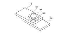
本実施形態の異材接合用アーク溶接法は、互いに重ね合わせされる、Al合金もしくはMg合金製の上板10(第1の板)と、鋼製の下板20(第2の板)とを、鋼製の接合補助部材30を介して、後述するアーク溶接法によって接合することで、図1A及び図1Bに示すような異材溶接継手1を得るものである。
In the arc welding method for joining dissimilar materials of the present embodiment, the upper plate 10 (first plate) made of Al alloy or Mg alloy and the lower plate 20 (second plate) made of steel are superposed on each other. , A dissimilar welded joint 1 as shown in FIGS. 1A and 1B is obtained by joining by an arc welding method described later via a steel joining
上板10の板厚以上の高さを有する接合補助部材30を上板10上に配置し、接合補助部材30に圧力をかけて上板10を打ち抜くことにより、上板10に穴11を形成する。打ち抜き加工により圧入された接合補助部材30は、穴11の周囲のAl合金もしくはMg合金材料から圧力を受けて、軽く拘束された状態となって固定される。
A
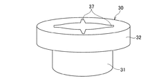
図2に示すように、接合補助部材30は、大径部32と、大径部32よりも最大外径が小さい小径部31とを持った段付きの外形形状を有する。また、接合補助部材30には、小径部31及び大径部32を貫通する中空部33が形成される。なお、大径部32の外形形状は、図2や図15Aに示すような円形に限定されず、接合補助部材30の圧入により形成された貫通部(穴11)をアーク溶接後に塞いでいれば、任意の形状とすることができる。つまり、図15B〜図15Eに示す四角形以上の多角形でもよい。また、図15Cに示すように、多角形の角部を丸くしてもよい。
As shown in FIG. 2, the joining
さらに、接合補助部材30の中空部33には、アーク溶接によってフィラー材(溶接材料)が溶融した、鉄合金、または、Ni合金の溶接金属40が充填されると共に、溶接金属40と、溶融された下板20及び接合補助部材30の一部とによって溶融部Wが形成される。
Further, the
以下、異材溶接継手1を構成する異材接合用アーク溶接法について、図3A〜図3Gを参照して説明する。
まず、図3Aに示すように、上板(第1の板)10の板厚以上の高さを有する接合補助部材30を上板10上に配置し、接合補助部材30に圧力をかけて上板10を打ち抜くことにより、上板10に穴11を形成しつつ、接合補助部材30を上板10に圧入する(ステップS1)。
次に、図3Fに示すように、接合補助部材30が圧入された上板10と、下板20を重ね合わせる重ね合わせ作業を行う(ステップS2)。そして、図3Gに示すように、以下に詳述する(a)溶極式ガスシールドアーク溶接法、(b)ノンガスアーク溶接法、(c)ガスタングステンアーク溶接法、(d)プラズマアーク溶接法、(e)被覆アーク溶接法のいずれかのアーク溶接作業を行うことで、上板10と下板20とを接合する(ステップS3)。なお、図3Gは、(a)溶極式ガスシールドアーク溶接法を用いてアーク溶接作業が行われた場合を示している。
Hereinafter, the arc welding method for joining dissimilar materials constituting the dissimilar material welded joint 1 will be described with reference to FIGS. 3A to 3G.
First, as shown in FIG. 3A, a joining
Next, as shown in FIG. 3F, an overlapping operation is performed in which the
ステップS1の打ち抜き作業を行うにあたり、接合補助部材30は大径部32及び小径部31を有しており、大径部32及び小径部31の合計高さが上板10の板厚以上となっている。また、接合補助部材30における小径部31が上板10に面するように配置される。
ステップS1の打ち抜き作業の具体的な手法としては、図3B〜図3Eに示すように、接合補助部材30自体をポンチとして、上板10が配置された下台座50に対して、接合補助部材30が固定された上台座51を接近させ、打抜き加工を施すことが挙げられる。この場合、中空部33に母材片Mが入り込んだままとなることが希にあり、アーク溶接時の邪魔になるので、その場合には母材片Mを取り除くことが必要である。
In performing the punching operation in step S1, the joining
As a specific method of punching work in step S1, as shown in FIGS. 3B to 3E, the joining
また、ステップS3のアーク溶接作業は、上板10の穴11内の溶接金属40を介して接合補助部材30と下板20を接合し、かつ接合補助部材30に設けられた中空部33を充填するために必要とされる。したがって、アーク溶接には充填材となるフィラー材(溶接材料)の挿入が不可欠となる。具体的に、以下の4つのアーク溶接法により、フィラー材が溶融して溶接金属40が形成される。
Further, in the arc welding work in step S3, the joining
(a) 溶極式ガスシールドアーク溶接法は、一般的にMAG(マグ)やMIG(ミグ)と呼ばれる溶接法であり、ソリッドワイヤもしくはフラックス入りワイヤをフィラー兼アーク発生溶極として用い、CO2,Ar,Heといったシールドガスで溶接部を大気から遮断して健全な溶接部を形成する手法である。 (A) The welded gas shielded arc welding method is a welding method generally called MAG or MIG, and uses a solid wire or a flux-cored wire as a filler and an arc generating electrode, and CO 2 , Ar, He, and other shield gases are used to shield the weld from the atmosphere to form a sound weld.
(b)ノンガスアーク溶接法は、セルフシールドアーク溶接法とも呼ばれ、特殊なフラックス入りワイヤをフィラー兼アーク発生溶極として用い、一方、シールドガスを不要として、健全な溶接部を形成する手段である。 (B) The non-gas arc welding method is also called a self-shielded arc welding method, and is a means for forming a sound welded portion by using a special flux-cored wire as a filler and an arc generating electrode, while eliminating the need for shield gas. is there.
(c)ガスタングステンアーク溶接法は、ガスシールドアーク溶接法の一種であるが非溶極式であり、一般的にTIG(ティグ)とも呼ばれる。シールドガスは、ArまたはHeの不活性ガスが用いられる。タングステン電極と母材との間にはアークが発生し、フィラーワイヤはアークに横から送給される。
一般的に、フィラーワイヤは通電されないが、通電させて溶融速度を高めるホットワイヤ方式TIGもある。この場合、フィラーワイヤにはアークは発生しない。
(C) The gas tungsten arc welding method is a kind of gas shielded arc welding method, but it is a non-welding type, and is generally also called TIG. As the shield gas, an Ar or He inert gas is used. An arc is generated between the tungsten electrode and the base metal, and the filler wire is fed to the arc from the side.
Generally, the filler wire is not energized, but there is also a hot wire type TIG that energizes and increases the melting rate. In this case, no arc is generated on the filler wire.
(d)プラズマアーク溶接法はTIGと原理は同じであるが、ガスの2重系統化と高速化によってアークを緊縮させ、アーク力を高めた溶接法である。 (D) The plasma arc welding method has the same principle as TIG, but is a welding method in which the arc is contracted and the arc force is increased by double systemization and speeding up of gas.
(e)被覆アーク溶接法は、金属の芯線にフラックスを塗布した被覆アーク溶接棒をフィラーとして用いるアーク溶接法であり、シールドガスは不要である。 (E) The shielded metal arc welding method is an arc welding method in which a shielded metal arc welding rod in which flux is applied to a metal core wire is used as a filler, and a shield gas is not required.
フィラー材(溶接材料)の材質については、溶接金属40がFe合金となるものであれば、一般的に用いられる溶接用ワイヤまたは溶接棒が適用可能である。なお、Ni合金でも鉄との溶接には不具合を生じないので適用可能である。
具体的には、JISとして(a)Z3312,Z3313,Z3317,Z3318,Z3321,Z3323,Z3334、(b)Z3313、(c)Z3316,Z3321,Z3334,(d)Z3211,Z3221,Z3223,Z3224、AWS(American Welding Society)として、(a)A5.9,A5.14,A5.18,A5.20,A5.22,A5.28,A5.29,A5.34、(b)A5.20、(c)A5.9,A5.14,A5.18,A5.28,(d)A5.1,A5.4,A5.5,A5.11といった規格材が流通している。
As for the material of the filler material (welding material), if the
Specifically, as JIS, (a) Z3312, Z3313, Z3317, Z3318, Z3321, Z3323, Z3334, (b) Z3313, (c) Z3316, Z3321, Z3334, (d) Z3211, Z3221, Z3223, Z3224, AWS As (American Welding Society), (a) A5.9, A5.14, A5.18, A5.20, A5.22, A5.28, A5.29, A5.34, (b) A5.20, ( c) Standard materials such as A5.9, A5.14, A5.18, A5.28, (d) A5.1, A5.4, A5.5, and A5.11 are on the market.
これらのアーク溶接法を用いて接合補助部材30の中空部33をフィラー材で充填するが、一般的にフィラーワイヤもしくは溶接棒の狙い位置は移動させる必要がなく、適切な送給時間を経てアークを切って溶接終了させれば良い。ただし、中空部33の面積が大きい場合は、フィラーワイヤもしくは溶接棒の狙い位置を中空部33内で円を描くように移動させても良い。
Although the
以上の作業によって、Al合金やMg合金製の上板10と鋼製の下板20は高い強度で接合される。
By the above work, the
以下、上記アーク溶接法において使用される鋼製の接合補助部材30の役割について説明する。
Hereinafter, the role of the steel joining
まず、接合補助部材を使用せず、図4A及び図4Bに示すように、単純にアルミ製の上板10と鋼製の下板20とを重ね、上板側から鋼もしくはニッケル合金製溶接ワイヤを用いたアーク溶接を定点で一定時間保持したアークスポット溶接を行った場合、形成される溶接金属40aはアルミと鋼、もしくはアルミと鋼とニッケルの合金となる。この合金は、アルミ含有量が多いので脆性的特性である金属間化合物(IMC)を呈している。
First, as shown in FIGS. 4A and 4B, the aluminum
このような異材溶接継手100aは、一見接合されている様に見えても、横方向に引張応力がかかる(せん断引張)と、図5A及び図5Bに示すように、溶接金属40aが容易に破壊して、外れてしまう。また、縦方向に引張応力がかかる(剥離引張)場合でも、図6A及び図6Bに示すように、溶接金属40aが破断するか、もしくは溶接金属40aと上板10の境界部あるいは溶接金属40aと下板20の境界部が破断し、上板10が抜けるようにして接合が外れてしまう。
このように単にアルミ製の上板10と鋼製の下板20を重ねて、貫通溶接しようとしても、溶接金属40aは全部分が金属間化合物になってしまうので、せん断引張にも剥離引張にも弱く、溶接継手としては実用にならない。
Even if such a dissimilar welded joint 100a seems to be joined, when tensile stress is applied in the lateral direction (shear tension), the
Even if an aluminum
また、図7A及び図7Bに示すように、上板10に適当なサイズの穴11を開けておき、その穴11を埋めるように鋼もしくはニッケル合金の溶接材料を溶かし込む手法が考えられる。
この場合、溶接初期に形成される下板20となっている鋼と溶接材料で形成される溶接金属40bはアルミを溶かしていないので、金属間化合物は生成せず、高い強度と靱性を有しており、下板20と強固に結合されている。また、上板10に開けられた穴11の内部に形成された溶接金属40bは、アルミが溶融する割合が非常に少なく、金属間化合物の生成は大幅に抑制され、特に中心部は健全性を有している。
Further, as shown in FIGS. 7A and 7B, a method is conceivable in which a
In this case, since the
ただし、上板10に設けられた穴11の近傍に限れば、アルミと鋼、あるいはアルミとニッケルの金属化合物層を形成する。このような異材溶接継手100bに対し、図8Aに示すように、せん断引張応力がかかった場合、下板側は強固に金属結合しているため、高い応力に耐える。一方、上板側は金属間化合物が穴周囲に形成されてはいるが、それが剥離して動くことは形状的にできないため、初期には上板10、下板20の母材が変形する。
このため、ほぼ変形せずに脆性破断する図5A及び図5Bの異材溶接継手100aと比較すると、変形能力の向上が見られる。しかし、母材の変形が進み、図8Bに示すように、接合部が90°近く傾斜すると上下剥離引張と同じ状態になる。このようになると穴11の周囲部に形成された金属間化合物が剥離し、上板10が溶接部から容易に抜けてしまう。つまり、改善が不十分である。
この結果は、図9A及び図9Bに示すように、上下引張方向試験でも無論同じである。
However, as long as it is limited to the vicinity of the
Therefore, as compared with the dissimilar welded joint 100a of FIGS. 5A and 5B in which the brittle fracture occurs with almost no deformation, the deformation ability is improved. However, as the deformation of the base metal progresses and the joint is tilted by about 90 ° as shown in FIG. 8B, the state becomes the same as the vertical peeling tension. When this happens, the intermetallic compound formed around the
This result is, of course, the same in the vertical tensile direction test as shown in FIGS. 9A and 9B.
上記2つの異材溶接継手100a、100bにおける課題から、せん断方向及び上下剥離方向の応力にも耐えるように、さらなる改良を施したのが本実施形態である。
すなわち、図3A〜図3Dに示すように、上板10となるアルミ板に対して、中心に穴が空いている鋼製の接合補助部材30を圧入する。接合補助部材30は上板10の板厚以上の高さを有するため、接合補助部材30が圧入された個所のその箇所のアルミ板は抜け落ちる(ステップS1:打ち抜き工程)。さらに、接合補助部材30は周囲のアルミ板から圧力を受けて、軽く拘束された状態となって固定される(図10C参照)。
From the problems of the above two dissimilar welded
That is, as shown in FIGS. 3A to 3D, the steel joining
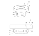
接合補助部材30を上板10に圧入するための圧入装置としては、例えば、図10Aまたは図10Bに示すように、接合補助部材30を上板10に押し込むための上台座51と、それを動かすための加圧機構80、及び上板10の裏側を受け止めるための下台座50で構成される。なお、図10Aは接合補助部材30を1個ずつ圧入するための圧入装置を示しており、図10Bは接合補助部材30を複数同時に圧入するための圧入装置を示している。
上台座51と接合補助部材30は、例えば、磁力や機械的機構によって一時的に保持され、圧入完了後は加圧方向(図10Aまたは図10B中の矢印)と逆方向に上台座51を引き上げることで、接合補助部材30を離脱させることができる。ここで、図3B及び図3Cに示すように、下台座50は接合補助部材30の挿入径以上の中空部を有しており、圧入によって抜き打ちされたAl合金もしくはMg合金の不要部を蓄積、あるいは排除することができる。なお、負圧による吸引機構を設けても良い。
また、これら一対の機構(上台座51,下台座50)は単独で装置としても良いし、複数を同時に駆動させる機構を持った装置としても良い。また、これらは定置式としても良いし、産業用多関節ロボットに持たせ、自由に場所を移動出来るようにしても良い。
As a press-fitting device for press-fitting the joining
The
Further, these pair of mechanisms (
次のステップとして、接合補助部材30が仮固定されたAl合金もしくはMg合金製の上板10と鋼製の下板20を、接合すべき位置に合わせて重ね合わせる(ステップS2:重ね合わせ工程)。このとき、接合補助部材30が仮固定された上板10と下板20とは出来る限り互いに密着している方が好ましい。
図11に示すように、上板10と下板20との間にギャップGが存在している場合、後の工程において上板10と下板20とが溶接されたとしても、上板10は下板20との隙間分だけ自由移動が可能な状態となってしまい、接合精度が悪くなる(がたつきが生じてしまう)からである。
As the next step, the
As shown in FIG. 11, when a gap G exists between the
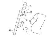
加圧せずとも、上板10及び下板20の密着性が確保される場合には必ずしも充填溶接工程時における加圧機構は必要ないが、上板10及び下板20は充填溶接工程時において、互いに密着する方向に加圧されていることが好ましい。
具体的には、加圧機構80であるクランプ機構を使って上下から加圧する場合(図12Aを参照)、あるいは片側から加圧する場合(図12Bを参照)が例として挙げられる。また、溶接トーチ90に加圧用脚92を設けて、ロボットなどの力で加圧する場合(図12Cまたは図12Dを参照)が例として挙げられる。
When the adhesion between the
Specifically, a case where the pressure is applied from above and below using the clamp mechanism which is the pressure mechanism 80 (see FIG. 12A) or a case where the pressure is applied from one side (see FIG. 12B) can be mentioned as an example. Further, a case where the
上板10と下板20との間にギャップGが存在している場合と同様の観点より、図13に示すように、接合補助部材30で上板10を打ち抜いたときの、接合補助部材30の小径部31における上板10からの張り出し量Pは少ないほど良い。張り出し量Pが多いほど、充填溶接後において、がたつきが生じる原因となり得る。具体的には、張り出し量Pは上板10の板厚BHに対し25%以下とするのが良い(ただし、上板10を確実に打ち抜くために、0%以上とする)。なお、より好ましくは10%以下、さらに好ましくは5%以下である。
From the same viewpoint as when a gap G exists between the
このように溶接前準備が整ったら、接合補助部材30における中空部33内を充填するようにアーク溶接にて溶接金属40を形成する。なお、アーク溶接用ワイヤや溶接棒先端の狙い位置は接合補助部材30ではなく、上板10の穴11における下面と接する、鋼製の下板20である。言い換えれば、接合補助部材30における中空部33内の壁と、下板20に囲われた”るつぼ”状の空間は、アーク溶接によって鋳造された状態になる。
このようにすると、断面としては接合補助部材30、溶接金属40、下板20が強固な金属結合によって溶接接合されている状態になる。
接合補助部材30における先端部(小径部31)による打ち抜き加工によって形成された穴径よりも幅広である接合補助部材30の大径部32は、上板10表面と面一、もしくは外側に配置される。この大径部32の最大の役割は、上下剥離応力に対する抵抗である。図14Aに示したように、外側に大径部32を有する接合補助部材30を適用することにより、上板10と溶接金属40の界面が剥離して抜けてしまう現象を防止することが可能となる。一般的には、図14Bに示したように、溶接金属40は、十分に塑性変形した後、破断する。なお、接合補助部材30は、せん断方向の引張応力に対しても、初期応力に対して何ら悪影響を及ぼさないことは自明である。
When the pre-welding preparation is completed in this way, the
In this way, the cross section is such that the joining
The
接合補助部材30における大径部32の外形形状は、そのメカニズム上、圧入による打ち抜きにより形成された穴11を溶接後に塞いでいれば、任意の形状とすることができる。例えば、最も一般的な形状は図15Aに示すような円形であるが、図15B〜図15Eに示す四角形以上の多角形でもよい。また、図15Cに示すように、多角形の角部を丸くしてもよい。
Due to its mechanism, the outer shape of the
また、接合補助部材30における大径部32の断面形状は、図16Aに示すような、平たい円柱状だけでなく、図16Bに示すような、上側(小径部31側とは反対側)にテーパーが付いた形状、あるいは図16Cに示すような、上側に丸みを持たせた形状など特に問わない。
Further, the cross-sectional shape of the
接合補助部材30は面積が大きく、かつ厚さが大きいほど板厚方向(3次元方向)の外部応力に対して強度を増すため、好ましい。しかし、必要以上に大きいと重量増の要因や、上板10表面からの張り出し量が過剰となることにより、美的外観劣化や近接する他の部材との干渉が生じるため、必要とされる設計に応じてサイズを決めることが好ましい。
The joining
接合補助部材30には、他にもいくつかの役割がある。その一つが上板10の材料であるAl合金やMg合金の溶融を避けるための防護壁作用である。融点が低いAl合金やMg合金は、アークが当たることにより、その高熱で溶融してしまう。しかし、接合補助部材30を介在させることで、アークがAl合金やMg合金に当たるのを物理的に防ぎ、溶融することを防止することができる。
また、アークにより形成される溶融金属40は高温であり、接触したAl合金やMg合金を侵食する場合があるため、アーク溶接中も接合補助部材30が介在していることが好ましい。すなわち、アーク溶接の終了後に、接合補助部材30の小径部31が溶接金属40と上板10の間に残っていることが好ましい。
アーク溶接の溶込み範囲が接合補助部材30と下板20のみとなれば、AlやMgの溶接金属40への希釈はゼロとなり、IMCは完全に防止される。なお、図17に示すように、接合補助部材30の半径方向における厚みが薄すぎると、アーク溶接時の入熱により、接合補助部材30が融点に達して溶けてしまうおそれがある。この場合、さらにAl合金やMg合金まで溶かす可能性があることから、溶接入熱を鑑みて、適切な厚みの設計とする必要がある。
The joining
Further, since the
If the penetration range of arc welding is only the joining
接合補助部材30における、上板10への押込み量は特に制限されない。しかし、図18Aに示すように、接合部が上板10の表面に対して凹んでしまうと、溶接後の継手に応力がかかった際、溶接金属40が応力集中部となって、低強度で破壊するおそれがある。よって、図18Bに示すように、少なくとも上板10の表面と接合補助部材30の表面が面一であるか、図18Cに示すように、接合補助部材30の大径部32が上板10の表面に対し、部分的に飛び出している状態が好ましい。さらには、図18Dに示すように、接合補助部材30の大径部32が上板10の表面に対し、完全に飛び出していることが最も好ましい。
The amount of pushing into the
接合補助部材30の小径部31の断面形状は、図2に示すように、最も一般的な形状として真円形が使われるが、特に限定されず、任意の形状とすることができる。例えば、図19A〜図19Fに示す四角形以上の多角形でもよい。また、図19Bに示すように、多角形の角部を丸くしてもよい。さらに、接合補助部材30における中空部33の内面形状についても、上記と同様、真円形である必要はなく、19A〜図19Eまたは図19Gに示すように、任意の形状とすることができる。なお、図19A〜図19Dに示すように、小径部31の断面形状と中空部の内面形状とが同一である必要はなく、図19Fや図19Gのように、異なっていても良い。
As shown in FIG. 2, the cross-sectional shape of the
また、接合補助部材30を上板10に対して圧入して打ち抜く際には、接合補助部材30を回しながら圧力をかけることも可能である。そのような手段を用いる場合は、図20に示すように、大径部32の上面にネジ回し用ドライバーがフィットするような切り欠き37を設けると、接合補助部材30を上板10に回し入れやすくすることができる。
Further, when the joining
接合補助部材30に空けられる中空部33の面は平坦でかまわないが、図21に示すように、ネジ溝33aを形成していてもかまわない。本工法において雄ネジは用いられないが、ネジ溝33aがあることで、アーク溶接時に溶融池との接触表面積が増え、より強固に溶接金属40と接合補助部材30が結合される。ネジ溝33aなど円筒面でない場合の穴の直径PSは、最も広い対面間距離と定義する。
The surface of the
接合補助部材30の材質は、純鉄及び鉄合金であれば制限は無く、詳しくは軟鋼、炭素鋼、ステンレス鋼などがあげられる。
The material of the joining
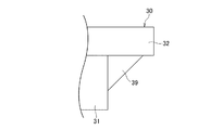
溶接金属40は接合補助部材30の中空部33を充填し、さらに接合補助部材30の表面、より具体的には大径部32の表面に余盛りWaを形成するのが望ましい(図1B参照)。余盛りWaを形成しない、すなわち、図22Aに示すように、中空部33が溶接後に外観上残る状態だと、特に、板厚方向(3次元方向)の外部応力に対しては、接合強度が不足となる可能性がある(図22B参照)。このため、余盛りWaを形成することで、図23に示すように、板厚方向(3次元方向)の外部応力に対しては、接合補助部材30の変形が抑えられ、高い接合強度が得られる。なお、板厚方向の引張応力に対して接合補助部材30を上板10に確実に固定するため、余盛りWaを板厚方向上側(上板10側)から見た場合の、余盛りWaの最大外径は、上板10に設けられる穴11の最大外径よりも大きくすることが好ましい。
It is desirable that the
一方、余盛り側と反対側の溶込みについては、図24Aに示すように、下板20の板厚を超えて溶接金属40が形成される、いわゆる裏波が出る状態にする必要がある。その理由は以下のとおりである。
溶接条件の設定不良あるいは溶接機器の動作不良等により溶込みが浅くなり、接合補助部材30に形成される表側の余盛りWaが外観的に正常であるにもかかわらず、下板20が溶けずに、溶接金属40が乗りかかっているだけという状態になることがある。このような場合、接合補助部材30と下板20は接合されていないことになり、つまり下板20と上板10も接合されていないことになる。
一方、下板20に裏波が生じている場合、それは溶接金属40が上板10側から会合面を通過して下板20側まで到達したことを意味しているので、接合補助部材30と下板20が金属結合されていることを保証することになる。さらに、それは間接的に上板10と下板20が接合されていることを保証することになる。すなわち、下板20に裏波が生じていれば、溶接工程直後にそれを目視あるいはセンサー等で容易に確認することが出来、接合不良をそのままにして後工程に進むことを防止することができる。
さらには、下板20に形成された裏波のサイズから、接合補助部材30と下板20の接合強度をおおよそ予想することができる。これらの間の接合強度は、用いられる材質を一定とした場合、上板10と下板20の界面に形成される溶接金属40の断面積、いわゆるナゲット径の大きさに比例する。ナゲット径は、接合補助部材30に設けられた中空部33が溶接金属40で満たされているとすると、中空部33の上面側(大径部32側)に形成された溶接金属40の直径(最大外径)を上底、裏波の直径(最大外径)を下底とした左右対称の台形断面として推定することができる。すなわち、ナゲット径は裏波の直径とおおよそ比例する。この関係性を利用して、単に接合されているか否かという2択論ではなく、必要強度を満たして接合されているか否かというレベルの高い品質保証を、下板20の裏波サイズの測定から実施することができる。このような品質保証性の点から、溶接金属40を下板20の外側に裏波が出る状態まで溶け込ませて、下板20と接合補助部材30を溶接することが必須である。
ただし、溶接金属40が深く溶け込みすぎて、溶接金属40と下板20が溶け落ちてしまわないように溶接する必要がある。
なお、図24Bに示すように、溶接金属40が下板20に適度に溶け込んでいるが、下板20に裏波が生じていない場合には、上記した品質保証のための検出を行うことができないため好ましくない。
On the other hand, with respect to the penetration on the side opposite to the surplus side, as shown in FIG. 24A, it is necessary to make a so-called back wave in which the
The penetration becomes shallow due to improper setting of welding conditions, malfunction of welding equipment, etc., and the
On the other hand, when a back wave is generated in the
Furthermore, the joint strength between the joint
However, it is necessary to weld so that the
As shown in FIG. 24B, when the
続いて、上記アーク溶接法において使用される接合補助部材30についての好ましい実施形態について説明する。
上述のように、上記打ち抜き工程(ステップS1)において、接合補助部材30を加圧して、上板10を打ち抜くと同時に、接合補助部材30を上板10に一時的に拘束保持することが可能である。しかし、稀に、溶接工程前に振動がかかる、あるいは上向姿勢になった際(図25を参照)に、拘束保持力の弱さが原因で脱落してしまうことがある。
Subsequently, a preferred embodiment of the joining
As described above, in the punching step (step S1), the joining
この問題を防ぎ、確実にアーク溶接工程(ステップS3)まで接合補助部材30を上板10に保持させるためには、接合補助部材30の保持力を高める手段が有効である。具体的には、接合補助部材30において、圧入後にかしめ機構を発揮させることのできる外観形状とすることで実現される。その手段の一つとして、図26A及び図26Bに示すように、接合補助部材30における小径部31の外周面には、羽根状に形成された、少なくとも1つ(本実施形態では4つ)の圧入用突起部39が設けられている。
In order to prevent this problem and ensure that the joining
図27は、圧入用突起部39を有する接合補助部材30が上板10に圧入される場合の保持機構を説明するための図である。図27に示すように、接合補助部材30を上板10へ圧入する際は、接合補助部材30と接する上板10が押し広げられる方向に弾性変形し、さらには塑性変形する。圧入用突起部39の先端部が通過した後は、弾性変形分が元の位置に戻る、すなわち上板10の材料であるAl合金もしくはMg合金の流入が起こり、接合補助部材30が押し戻される力に対して障壁要因となる。したがって、容易に接合補助部材30が外れることはない。
FIG. 27 is a diagram for explaining a holding mechanism when the joining
圧入用突起部39の形状は、図28Aに示すような2等辺三角形でもよいが、図28B〜図28Kに示すように、変形三角形、直角三角形、長方形、不定形状、ノコ刃状、半円、1/4円、対称台形、非対称台形、かぎ針状などが典型的で、その形状に制限はない。また、圧入用突起部39は、大径部32の下面とも接続されていることで、圧入用突起部39の強度を向上できる。さらに、圧入用突起部39は、図29Aに示すように、小径部31の軸方向に平行でもよいし、図29Bに示すように軸方向に対して傾きを持たせてもよい。この場合、接合補助部材30を回転させながら圧入するのに好適である。また、図29Cに示すように、圧入用突起部39は、基部から先端部に向けて円周方向幅が狭くなるような山形状であってもよい。さらに、圧入用突起部39の位置は、金属流入させる空間を設けるために大径部32から離れていることが好ましい。
The shape of the press-fitting
圧入用突起部39の数は、図26Bに示すような4枚に限定されず、少なくとも1枚あればよく、上限は特に設ける必要はない。すなわち、図30A〜図30Eに示すように、1枚、2枚、3枚、6枚、8枚の圧入用突起部39を有するものであってもよい。ただし、圧入用突起部39の枚数が増えると、接合補助部材30を用いて上板10を打ち抜くために必要な圧力が上がるので、圧入用突起部39の数を、必要以上に増やすべきではない。圧入用突起部39の数は、8枚以下とするのが好ましい。
また、図26Bや図30B〜図30Eに示すように、少なくとも2つの圧入用突起部39の最大外径部と接する最大円Cの直径、あるいは、図30Aに示すように、1つの圧入用突起部39の最大外径部と小径部31の外周面と接する円Cの直径が大きすぎる場合にも、上板10を打ち抜くために必要な圧力が上がるので、小径部31の外周面からの圧入用突起部39の突出量を、必要以上に増やすべきではない。
The number of press-fitting
Further, as shown in FIGS. 26B and 30B to 30E, the diameter of the maximum circle C in contact with the maximum outer diameter portion of at least two press-fitting
接合補助部材30の小径部31に圧入用突起部39を設けることには、他にも長所がある。第二の効果は接合対象である上板10と下板20が相互に回転しにくくなることである。接合補助部材30の小径部31の断面形状が真円形では、披接合部材(上板10及び下板20)が本接合法のみで接合される場合、例えば上板10に強い水平方向の回転力FRが加わると、接合補助部材30を中心に回るように上板10が回転してしまう可能性がある。しかしながら、図31A及び図31Bに示すように、接合補助部材30には圧入用突起部39が設けられていて、圧入用突起部39が上板10の穴11の周囲に食い込むことで、容易に回転を防止することができる。
Providing the press-fitting
なお、図32A〜図32Eにそれぞれ示される、直角三角形、長方形、1/4円、凹、非対称台形の圧入用突起部39のように、圧入用突起部39が大径部32と連続的となっていて、くびれ箇所を持たないものであっても、適用することは許容される。しかし、上述したような、接合補助部材30を上板10に圧入する際における、金属流入箇所が確保できないため、一時拘束性向上の効果はあまり期待できない。ただし、上記した回転抑制効果は期待できるため、このような形態であっても、小径部31の外周面には圧入用突起部39を有していることが好ましい。
The press-fitting
さらに、上記アーク溶接法において使用される接合補助部材30についての別の好ましい実施形態について説明する。
上記で説明したのと同様に、確実にアーク溶接工程(ステップS3)まで接合補助部材30を上板10に保持させるための別の手段として、小径部31に圧入用突起部39を設けるのではなく、小径部31の胴径を多段化し、部分的に”くびれ”を設ける策も有効である。
具体的には、図33A〜図33Hに示すように、接合補助部材30における小径部31の外周面に、大径部32の最大外径よりも小さい中径部34を設ける。なお、中径部34は、大径部32とは接触することなく、かつ、小径部31の外周面に沿って連続的(図33A、図33C、図33E〜図33H)または断続的(図33Bまたは図33D)に設けられる。
上記要件を満足する中径部34を小径部31の外周面に設けることにより、上板10に圧入される接合補助部材30の一部にくびれ部38が存在することとなる。
Further, another preferred embodiment of the joining
Similar to the above description, as another means for surely holding the joining
Specifically, as shown in FIGS. 33A to 33H, a
By providing the
これらの例に共通することは、[1]小径部31の先端側に中径部34を有すること、[2]中径部34と大径部32の間に小径部31を有すること、[3]非挿入側に大径部32を有すること、の相対関係が成立していることである。なお、図33Fに示すように、中径部34と小径部31がそれぞれ複数存在する場合も考えられるが、このことは上記各要件から無視して問題はなく、あくまで接合補助部材30の長手方向(挿入方向)に大径−小径−中径の関係が成立している並びが1箇所以上存在していれば、上記要件を満足する。
What is common to these examples is that [1] the
このような状態となれば、接合補助部材30に圧入用突起部39を設ける場合の実施形態で説明したと同じ原理により、容易に接合補助部材30が外れることはない。すなわち、接合補助部材30の圧入時に中径部34が通過する際にAl合金もしくはMg合金が弾性変形、さらには塑性変形し、さらに圧入が進み小径部31になると弾性変形分が戻る。これにより、金属流入が起きて、接合補助部材30が押し戻される力に対して障壁要因となる。
In such a state, the joining
なお、小径部31の全周に渡って中径部34を設けるのではなく、図33Bや図33Dに示すように、部分的にのみ中径部34を設けること、すなわち断続状にしてもよい。断続状にすると、圧入用突起部39を設けた場合と同様、接合補助部材30の挿入部分である小径部31が真円形状の場合に、上板10と下板20が溶接後にも相対的に容易に回転することを防ぐ効果が期待される。
In addition, instead of providing the
なお、図34A〜図34Dに示すように、大径部32と中径部34が、接合補助部材30の長手方向(挿入方向)から見て連続的となっている接合補助部材30であっても、適用することは許容される。しかし、上述したような、接合補助部材30を上板10に圧入する際における、金属流入箇所が確保できないため、一時拘束性向上の効果や回転抑制効果は期待できない。ただし、中径部34が断続状であれば、回転抑制効果のみ得られる。
As shown in FIGS. 34A to 34D, the
ところで、本実施形態における接合補助部材30は、図35Aに示すように、大径部32の上側に小径部31を積み重ねた形状とすることもできる。しかし、大径部32から見てAl合金やMg合金に打ち込まれる挿入方向反対側は、それが上板10の表面よりも高い位置にある場合(図35Bや図35Cにおいて、突出部35と定義する)は、継手強度には影響を及ぼさない。
一方、図35D〜図35Gに示すように、大径部32の上側に設けられた小径部31または中径部34の少なくとも一部が、上板10の表面よりも低い位置にある場合には、その部位が少なからず継手強度に影響を及ぼす。
By the way, as shown in FIG. 35A, the joining
On the other hand, as shown in FIGS. 35D to 35G, when at least a part of the
なお、上板10及び下板20の板厚については、限定される必要は必ずしもないが、施工能率と、重ね溶接としての形状を考慮すると、上板10の板厚は、5.0mm以下であることが望ましい。一方、アーク溶接の入熱を考慮すると、板厚が過度に薄いと溶接時に溶け落ちてしまい、溶接が困難であることから、上板10、下板20共に0.5mm以上とすることが望ましい。
The thickness of the
以上の構成により、上板10がAl合金もしくはMg合金、下板20が鋼の素材を強固に接合することができる。
With the above configuration, the
ここで、異種金属同士を直接接合する場合の課題としては、IMCの形成という課題以外に、もう一つの課題が知られている。それは、異種金属同士が接すると、ガルバニ電池を形成する為に腐食を加速する原因になる。この原因(電池の陽極反応)による腐食は電食と呼ばれている。異種金属同士が接する面に水があると腐食が進むので、接合箇所として水が入りやすい場所に本実施形態が適用される場合は、電食防止を目的として、水の浸入を防ぐためのシーリング処理を施す必要がある。本接合法でもAl合金やMg合金と鋼が接する面は複数形成されるので、樹脂系の接着剤をさらなる継手強度向上の目的のみならず、シーリング材として用いることが好ましい。 Here, as a problem in the case of directly joining dissimilar metals to each other, another problem is known in addition to the problem of forming IMC. When dissimilar metals come into contact with each other, it causes accelerated corrosion to form a galvanic cell. Corrosion due to this cause (anode reaction of the battery) is called electrolytic corrosion. If there is water on the surface where dissimilar metals come into contact with each other, corrosion will proceed. Therefore, when this embodiment is applied to a place where water easily enters as a joint, sealing to prevent water from entering for the purpose of preventing electrolytic corrosion. It needs to be processed. Since a plurality of surfaces in contact with the Al alloy or Mg alloy and the steel are formed even in this joining method, it is preferable to use a resin-based adhesive not only for the purpose of further improving the joint strength but also as a sealing material.
例えば、図36A及び図36Bに示す変形例のように、上板10と下板20との重ね合わせ工程の前に、上板10及び下板20の接合面で、溶接部周囲に接着剤60を全周に亘って環状に塗布してもよい。なお、接着剤60を上板10及び下板20の接合面で、溶接部周囲に全周に亘って塗布する方法としては、図37A及び図37Bに示す変形例のように、溶接箇所を除いた接合面の全面に塗布する場合も含まれる。これにより、上板10、下板20、及び溶接金属40の電食速度を下げることができる。
For example, as in the modified examples shown in FIGS. 36A and 36B, before the step of superimposing the
また、上述の打ち抜き工程において、接合補助部材30と、接合補助部材30と対向する上板10との間の少なくとも一方の対向面に、接着剤60を塗布してもよい。これにより、上板10、接合補助部材30、及び溶接金属40の電食速度を下げることができる。
この場合、副次的効果として、アーク溶接前に接合補助部材30を上板10に仮止めしておく作用がある。特に、図25に示すように、アーク溶接が、横向や上向姿勢になる場合、接着剤60を塗布しておくことで、接合補助部材30が重力によって落下するのを防ぐことができ、溶接を適切に施工することができる。
Further, in the punching step described above, the adhesive 60 may be applied to at least one facing surface between the joining
In this case, as a secondary effect, there is an action of temporarily fixing the joining
さらに、図38A及び図38Bに示す変形例のように、接合補助部材30の大径部32と上板10の表面との境界部に接着剤60を塗布してもよい。また、図38Cに示すように、大径部32全体を覆い隠してしまうように接着剤60を塗布してもよい。これにより、接合補助部材30と、Al合金もしくはMg合金の接する露出面側の表面、接合補助部材30における大径部32の下になっている隠れ面、さらに接合補助部材30による打ち抜き端面における、電食速度低下の効果が得られる。また、接着剤塗布をアーク溶接前に行えば、接合補助部材30を上板10に仮止めしておく効果も得られる。なお、本変形例では、接着剤の塗布は、溶接工程前(打ち抜き工程の際)でも充填溶接工程後でも可能である。
なお、接合補助部材30には、接着剤やシーリング材による電食抑制手段だけではなく、自身の錆防止や、アルミニウム板との間に生じる電食を防ぐために、電気的卑の元素や加工物、絶縁性物質、不動態といった皮膜を形成する表面処理を施すことが、さらに良い。例えば、亜鉛めっき、クロムめっき、ニッケルめっき、アルミめっき、錫(すず)めっき、樹脂塗装、セラミックコーティングなどがあげられる。
Further, as in the modified examples shown in FIGS. 38A and 38B, the adhesive 60 may be applied to the boundary portion between the
In addition, the joining
以上の構成により、上板10がAl合金もしくはMg合金、下板20が鋼の素材を開断面構造、閉断面構造にかかわらず強固に接合することができる。さらには接着剤を併用することにより、接合強度の向上と共に腐食を防ぐことも出来る。
また、本実施形態の溶接法は、接合面積が小さい点溶接と言えるので、ある程度の接合面積を有する実用部材同士の重ね合わせ部分Jを接合する場合は、本溶接法を図39A〜図39Cに示すように、複数実施すればよい。これにより、重ね合わせ部分Jにおいて強固な接合が行われる。本実施形態は、図39B及び図39Cに示すような開断面構造にも使用できるが、特に、図39Aに示すような閉断面構造において好適に使用することができる。
With the above configuration, the
Further, since the welding method of the present embodiment can be said to be spot welding with a small joining area, when joining the superposed portion J of practical members having a certain joining area, the welding method is shown in FIGS. 39A to 39C. As shown, a plurality of implementations may be performed. As a result, a strong joint is performed at the overlapped portion J. This embodiment can also be used for an open cross-section structure as shown in FIGS. 39B and 39C, but can be particularly preferably used for a closed cross-section structure as shown in FIG. 39A.
また、図40に示される開断面部材の製造プロセス及び図41に示される閉断面部材の製造プロセスのように、本接合法では溶接前工程として、接合補助部材30を上板10内に埋め込んでしまうことも可能である。上板10内に埋め込まれた接合補助部材30は、上板10の表面上に突き出ないことから、埋め込み後に金型等を用いてAlやMg母材をプレス成形することが容易であり、その後工程として、下板20と合わせて接合することが可能である。本溶接法は、無論、開断面部材、閉断面部材を分け隔てることなく、いずれも製造可能である。
Further, as in the manufacturing process of the open cross-section member shown in FIG. 40 and the manufacturing process of the closed cross-section member shown in FIG. 41, in this joining method, the joining
尚、本発明は、前述した実施形態及び実施例に限定されるものではなく、適宜、変形、改良、等が可能である。 The present invention is not limited to the above-described embodiments and examples, and can be appropriately modified, improved, and the like.
1 異材溶接継手
10 上板(第1の板)
11 穴
20 下板(第2の板)
30 接合補助部材
31 小径部
32 大径部
33 中空部
34 中径部
35 突出部
37 切り欠き
38 くびれ部
39 圧入用突起部
40 溶接金属
50 下台座
51 上台座
60 接着剤
80 加圧機構
90 溶接トーチ
92 加圧用脚
W 溶融部
Wa 余盛り
M 母材片
G ギャップ
P 張り出し量
J 重ね合わせ部分
1 Welded joint made of
11
30 Joining
Claims (11)
大径部と、該大径部よりも最大外径が小さい小径部とを持った段付きの外形形状を有し、且つ、該大径部及び該小径部を貫通する中空部が形成され、該大径部及び該小径部の合計高さが前記第1の板の板厚以上である鋼製の接合補助部材を、前記小径部が前記第1の板に面するように配置し、前記接合補助部材に圧力をかけて前記第1の板を打ち抜く、打ち抜き工程と、
前記第1の板と前記第2の板を重ね合わせる、重ね合わせ工程と、
以下の(a)〜(e)のいずれかの手法によって、前記接合補助部材の中空部を溶接金属で充填すると共に、前記溶接金属を前記第2の板に裏波が出る状態まで溶け込ませて、前記第2の板及び前記接合補助部材を溶接する、充填溶接工程と、
を備える異材接合用アーク溶接法。
(a)鉄合金、または、Ni合金の前記溶接金属が得られる溶接ワイヤを溶極として用いるガスシールドアーク溶接法。
(b)前記溶接ワイヤを溶極として用いるノンガスアーク溶接法。
(c)前記溶接ワイヤを非溶極フィラーとして用いるガスタングステンアーク溶接法。
(d)前記溶接ワイヤを非溶極フィラーとして用いるプラズマアーク溶接法。
(e)鉄合金、または、Ni合金の前記溶接金属が得られる被覆アーク溶接棒を溶極として用いる被覆アーク溶接法。 An arc welding method for joining dissimilar materials, in which a first plate made of an aluminum alloy or a magnesium alloy and a second plate made of steel are joined.
A hollow portion having a stepped outer shape having a large diameter portion and a small diameter portion having a smaller maximum outer diameter than the large diameter portion and penetrating the large diameter portion and the small diameter portion is formed. A steel joining auxiliary member having a total height of the large diameter portion and the small diameter portion equal to or larger than the plate thickness of the first plate is arranged so that the small diameter portion faces the first plate. A punching process in which pressure is applied to the joining auxiliary member to punch out the first plate.
A stacking step of superimposing the first plate and the second plate,
By any of the following methods (a) to (e), the hollow portion of the joining auxiliary member is filled with the welding metal, and the welding metal is melted into the second plate until a back wave appears. , The filling welding step of welding the second plate and the joining auxiliary member,
An arc welding method for joining dissimilar materials.
(A) A gas shielded arc welding method using a welding wire from which the weld metal of an iron alloy or a Ni alloy is obtained as a welding electrode.
(B) A non-gas arc welding method using the welding wire as a welding electrode.
(C) A gas tungsten arc welding method using the welding wire as a non-melting electrode filler.
(D) A plasma arc welding method using the welding wire as a non-welding filler.
(E) A shielded metal arc welding method using a shielded metal arc welding rod from which the weld metal of an iron alloy or a Ni alloy can be obtained as a welding electrode.
前記加圧機構が前記第1の板及び前記第2の板が互いに密着するように押圧しながら、前記第2の板及び前記接合補助部材を溶接する、請求項1〜7のいずれか1項に記載の異材接合用アーク溶接法。 In the filling welding step, the first plate and the second plate have a pressurizing mechanism capable of pressing in a direction in which they are in close contact with each other.
Any one of claims 1 to 7, wherein the pressurizing mechanism welds the second plate and the joining auxiliary member while pressing the first plate and the second plate so as to be in close contact with each other. The arc welding method for joining dissimilar materials described in.
Priority Applications (5)
| Application Number | Priority Date | Filing Date | Title |
|---|---|---|---|
| JP2018035397A JP6829218B2 (en) | 2018-02-28 | 2018-02-28 | Arc welding method for joining dissimilar materials |
| US16/971,481 US20200384567A1 (en) | 2018-02-28 | 2019-01-25 | Arc welding method for dissimilar material bonding |
| PCT/JP2019/002577 WO2019167502A1 (en) | 2018-02-28 | 2019-01-25 | Arc welding method for dissimilar material bonding |
| CN201980015962.5A CN111801189B (en) | 2018-02-28 | 2019-01-25 | Arc welding method for joining dissimilar materials |
| EP19760175.0A EP3744465A4 (en) | 2018-02-28 | 2019-01-25 | Arc welding method for dissimilar material bonding |
Applications Claiming Priority (1)
| Application Number | Priority Date | Filing Date | Title |
|---|---|---|---|
| JP2018035397A JP6829218B2 (en) | 2018-02-28 | 2018-02-28 | Arc welding method for joining dissimilar materials |
Related Child Applications (1)
| Application Number | Title | Priority Date | Filing Date |
|---|---|---|---|
| JP2020202990A Division JP6999015B2 (en) | 2020-12-07 | 2020-12-07 | Arc welding method for joining dissimilar materials |
Publications (2)
| Publication Number | Publication Date |
|---|---|
| JP2019150831A JP2019150831A (en) | 2019-09-12 |
| JP6829218B2 true JP6829218B2 (en) | 2021-02-10 |
Family
ID=67808835
Family Applications (1)
| Application Number | Title | Priority Date | Filing Date |
|---|---|---|---|
| JP2018035397A Active JP6829218B2 (en) | 2018-02-28 | 2018-02-28 | Arc welding method for joining dissimilar materials |
Country Status (5)
| Country | Link |
|---|---|
| US (1) | US20200384567A1 (en) |
| EP (1) | EP3744465A4 (en) |
| JP (1) | JP6829218B2 (en) |
| CN (1) | CN111801189B (en) |
| WO (1) | WO2019167502A1 (en) |
Families Citing this family (8)
| Publication number | Priority date | Publication date | Assignee | Title |
|---|---|---|---|---|
| WO2020084971A1 (en) * | 2018-10-23 | 2020-04-30 | 株式会社神戸製鋼所 | Arc welding method for joining dissimilar materials, joining assist member, dissimilar material welded joint, and plate material equipped with joining assist member |
| EP3957425A4 (en) * | 2019-04-19 | 2022-06-22 | Panasonic Intellectual Property Management Co., Ltd. | Junction structure |
| JP7290521B2 (en) * | 2019-09-18 | 2023-06-13 | ファナック株式会社 | Welding tools for robots and robots |
| JP7214601B2 (en) * | 2019-09-18 | 2023-01-30 | 株式会社神戸製鋼所 | Joining method and joined body |
| JP7319223B2 (en) * | 2020-04-17 | 2023-08-01 | 株式会社神戸製鋼所 | Arc spot welding method for joining dissimilar materials |
| WO2022050147A1 (en) * | 2020-09-01 | 2022-03-10 | パナソニックIpマネジメント株式会社 | Joining method |
| CN116096522A (en) * | 2020-09-01 | 2023-05-09 | 松下知识产权经营株式会社 | Joint structure |
| CN113146039B (en) * | 2021-04-28 | 2022-10-28 | 南昌大学 | Preparation and welding method of intermediate layer composite powder for laser welding of magnesium alloy steel |
Family Cites Families (21)
| Publication number | Priority date | Publication date | Assignee | Title |
|---|---|---|---|---|
| US2860230A (en) * | 1955-01-04 | 1958-11-11 | Kellogg M W Co | Fastening means and method |
| US3095951A (en) * | 1960-01-11 | 1963-07-02 | Gen Electric | Article and method for joining dissimilar materials |
| US3624344A (en) * | 1968-08-02 | 1971-11-30 | Carborundum Co | Attachment of nonmetallic articles to metallic substrates |
| JPS52114446A (en) * | 1976-03-22 | 1977-09-26 | Fuji Heavy Ind Ltd | Method of joining members of different materials |
| JPS54100946A (en) * | 1978-01-26 | 1979-08-09 | Hitachi Metals Ltd | Line welding method |
| US4359599A (en) * | 1980-02-13 | 1982-11-16 | Westinghouse Electric Corp. | Electrical conductor connection and method of making same |
| JP2002174219A (en) | 2000-12-06 | 2002-06-21 | Toyota Motor Corp | Self-piercing rivet and fastening method |
| JP5044128B2 (en) | 2006-03-22 | 2012-10-10 | 本田技研工業株式会社 | Friction stir welding method and friction stir welding member for aluminum alloy and steel plate |
| CN201087750Y (en) * | 2007-05-17 | 2008-07-16 | 东风汽车公司 | Corrosion-resistant riveted structure of different metal connectors |
| US7819452B2 (en) * | 2008-05-12 | 2010-10-26 | United States Council For Automotive Research | Automotive structural joint and method of making same |
| JP2009285678A (en) * | 2008-05-28 | 2009-12-10 | Kobe Steel Ltd | Dissimilar material joining method and dissimilar material joined body between steel and light alloy, light alloy for joining dissimilar material for steel, and dissimilar material joining rivet between steel and light alloy |
| DE102012102286A1 (en) * | 2012-03-19 | 2013-09-19 | Thyssenkrupp Steel Europe Ag | A method of bonding a composite sheet to a metallic substrate |
| JP6022402B2 (en) * | 2013-05-22 | 2016-11-09 | 株式会社神戸製鋼所 | Rivet joint structure and manufacturing method thereof |
| JP5722479B2 (en) * | 2013-07-22 | 2015-05-20 | 株式会社神戸製鋼所 | Dissimilar material joining rivet, dissimilar material joining member, dissimilar material joining method, and dissimilar material joining |
| JP6148136B2 (en) * | 2013-09-24 | 2017-06-14 | 株式会社神戸製鋼所 | Manufacturing method of dissimilar material joined body |
| MX2017007878A (en) * | 2014-12-15 | 2018-02-13 | Arconic Inc | Resistance welding fastener, apparatus and methods for joining similar and dissimilar materials. |
| CN108883484B (en) * | 2016-03-30 | 2020-09-15 | 松下知识产权经营株式会社 | Joint structure |
| EP3498410A4 (en) * | 2016-08-09 | 2019-08-21 | Panasonic Intellectual Property Management Co., Ltd. | Junction structure |
| JP6461056B2 (en) * | 2016-08-29 | 2019-01-30 | 株式会社神戸製鋼所 | Arc spot welding method for joining dissimilar materials, joining auxiliary member, and dissimilar material welding joint |
| JP2018035397A (en) | 2016-08-31 | 2018-03-08 | 株式会社神戸製鋼所 | Hydrogen storage alloy and hydrogen purification device |
| JP6740287B2 (en) * | 2018-07-05 | 2020-08-12 | ファナック株式会社 | Tool for joining dissimilar metals |
-
2018
- 2018-02-28 JP JP2018035397A patent/JP6829218B2/en active Active
-
2019
- 2019-01-25 CN CN201980015962.5A patent/CN111801189B/en active Active
- 2019-01-25 EP EP19760175.0A patent/EP3744465A4/en not_active Withdrawn
- 2019-01-25 WO PCT/JP2019/002577 patent/WO2019167502A1/en unknown
- 2019-01-25 US US16/971,481 patent/US20200384567A1/en active Pending
Also Published As
| Publication number | Publication date |
|---|---|
| EP3744465A1 (en) | 2020-12-02 |
| WO2019167502A1 (en) | 2019-09-06 |
| EP3744465A4 (en) | 2021-04-28 |
| CN111801189A (en) | 2020-10-20 |
| CN111801189B (en) | 2022-03-18 |
| JP2019150831A (en) | 2019-09-12 |
| US20200384567A1 (en) | 2020-12-10 |
Similar Documents
| Publication | Publication Date | Title |
|---|---|---|
| JP6829218B2 (en) | Arc welding method for joining dissimilar materials | |
| CN109641307B (en) | Arc spot welding method for dissimilar metal joining, joining auxiliary member, and dissimilar metal welded joint | |
| EP3517243A1 (en) | Spot welding method for joining different materials, joining assistance member, and different material welded joint | |
| CN110114181B (en) | Arc welding method for joining dissimilar materials, joining auxiliary member, welded joint of dissimilar materials, and plate material with joining auxiliary member | |
| JP7017501B2 (en) | Welding method for joining dissimilar materials, joining auxiliary members, and welded joints made of dissimilar materials | |
| WO2018042680A1 (en) | Arc-spot welding method for joining different materials, joining auxiliary member, and different materials welding joint | |
| JP2018103240A (en) | Arc-welding method for joining dissimilar materials, joining auxiliary member, dissimilar material weld joint, and plate with joining auxiliary member | |
| JP2010207886A (en) | Method for joining dissimilar material | |
| JP6999015B2 (en) | Arc welding method for joining dissimilar materials | |
| EP3517240A1 (en) | Arc welding method for joining different materials, joining assistance member, and different material welded joint | |
| EP3505290A1 (en) | Arc-spot welding method for joining different materials, joining auxiliary member, and different materials welding joint | |
| JP3617585B2 (en) | Method of lining titanium or titanium alloy material to steel | |
| JP7160625B2 (en) | Arc Stud Welding Method for Joining Dissimilar Materials and Joining Auxiliary Member | |
| WO2018042682A1 (en) | Arc-welding method for joining different materials, joining auxiliary member, and different materials welding joint | |
| JP2018103241A (en) | Arc-welding method for joining dissimilar materials, joining auxiliary member, dissimilar material weld joint, and plate with joining auxiliary member | |
| JP7131927B2 (en) | Dissimilar Material Joining Method, Joining Auxiliary Member, and Dissimilar Material Joining Joint | |
| WO2020084971A1 (en) | Arc welding method for joining dissimilar materials, joining assist member, dissimilar material welded joint, and plate material equipped with joining assist member | |
| JP7025489B2 (en) | Arc welding method for joining dissimilar materials, joining auxiliary members, and welded joints made of dissimilar materials | |
| JP7111665B2 (en) | Arc stud welding method for joining dissimilar materials | |
| JP7256498B2 (en) | Arc Stud Welding Method for Joining Dissimilar Materials, Joining Auxiliary Member, and Welded Joint of Dissimilar Materials |
Legal Events
| Date | Code | Title | Description |
|---|---|---|---|
| A621 | Written request for application examination |
Free format text: JAPANESE INTERMEDIATE CODE: A621 Effective date: 20200818 |
|
| A621 | Written request for application examination |
Free format text: JAPANESE INTERMEDIATE CODE: A621 Effective date: 20200831 |
|
| A871 | Explanation of circumstances concerning accelerated examination |
Free format text: JAPANESE INTERMEDIATE CODE: A871 Effective date: 20200831 |
|
| A975 | Report on accelerated examination |
Free format text: JAPANESE INTERMEDIATE CODE: A971005 Effective date: 20201023 |
|
| A131 | Notification of reasons for refusal |
Free format text: JAPANESE INTERMEDIATE CODE: A131 Effective date: 20201027 |
|
| A521 | Written amendment |
Free format text: JAPANESE INTERMEDIATE CODE: A523 Effective date: 20201207 |
|
| TRDD | Decision of grant or rejection written | ||
| A01 | Written decision to grant a patent or to grant a registration (utility model) |
Free format text: JAPANESE INTERMEDIATE CODE: A01 Effective date: 20210105 |
|
| A61 | First payment of annual fees (during grant procedure) |
Free format text: JAPANESE INTERMEDIATE CODE: A61 Effective date: 20210121 |
|
| R150 | Certificate of patent or registration of utility model |
Ref document number: 6829218 Country of ref document: JP Free format text: JAPANESE INTERMEDIATE CODE: R150 |