JP6828608B2 - Game machine - Google Patents
Game machine Download PDFInfo
- Publication number
- JP6828608B2 JP6828608B2 JP2017118062A JP2017118062A JP6828608B2 JP 6828608 B2 JP6828608 B2 JP 6828608B2 JP 2017118062 A JP2017118062 A JP 2017118062A JP 2017118062 A JP2017118062 A JP 2017118062A JP 6828608 B2 JP6828608 B2 JP 6828608B2
- Authority
- JP
- Japan
- Prior art keywords
- displayed
- image
- symbol
- special symbol
- control device
- Prior art date
- Legal status (The legal status is an assumption and is not a legal conclusion. Google has not performed a legal analysis and makes no representation as to the accuracy of the status listed.)
- Active
Links
- 230000000694 effects Effects 0.000 claims description 1087
- 238000004519 manufacturing process Methods 0.000 claims description 101
- 230000001965 increasing effect Effects 0.000 claims description 29
- 238000009877 rendering Methods 0.000 claims description 11
- 230000015572 biosynthetic process Effects 0.000 claims description 8
- 238000000034 method Methods 0.000 description 2007
- 230000008569 process Effects 0.000 description 1977
- 238000012545 processing Methods 0.000 description 545
- 230000000875 corresponding effect Effects 0.000 description 490
- 238000003860 storage Methods 0.000 description 481
- 238000012546 transfer Methods 0.000 description 384
- 239000000872 buffer Substances 0.000 description 317
- 230000033458 reproduction Effects 0.000 description 214
- HAORKNGNJCEJBX-UHFFFAOYSA-N cyprodinil Chemical compound N=1C(C)=CC(C2CC2)=NC=1NC1=CC=CC=C1 HAORKNGNJCEJBX-UHFFFAOYSA-N 0.000 description 205
- 230000008859 change Effects 0.000 description 178
- 241001342895 Chorus Species 0.000 description 127
- 238000010586 diagram Methods 0.000 description 119
- JEIPFZHSYJVQDO-UHFFFAOYSA-N iron(III) oxide Inorganic materials O=[Fe]O[Fe]=O JEIPFZHSYJVQDO-UHFFFAOYSA-N 0.000 description 103
- 238000001514 detection method Methods 0.000 description 100
- 230000001960 triggered effect Effects 0.000 description 92
- 230000008707 rearrangement Effects 0.000 description 68
- 230000002829 reductive effect Effects 0.000 description 58
- 238000009826 distribution Methods 0.000 description 57
- 230000008901 benefit Effects 0.000 description 44
- 230000007704 transition Effects 0.000 description 38
- 238000003825 pressing Methods 0.000 description 31
- 238000010304 firing Methods 0.000 description 28
- 230000003111 delayed effect Effects 0.000 description 25
- 230000006798 recombination Effects 0.000 description 21
- 238000005215 recombination Methods 0.000 description 21
- 230000005540 biological transmission Effects 0.000 description 20
- 238000012544 monitoring process Methods 0.000 description 19
- 238000012790 confirmation Methods 0.000 description 15
- 230000002844 continuous effect Effects 0.000 description 15
- 230000001276 controlling effect Effects 0.000 description 13
- 230000033228 biological regulation Effects 0.000 description 10
- 230000004044 response Effects 0.000 description 9
- 238000002156 mixing Methods 0.000 description 8
- 230000005856 abnormality Effects 0.000 description 7
- 239000003086 colorant Substances 0.000 description 7
- 238000013461 design Methods 0.000 description 7
- 239000000284 extract Substances 0.000 description 7
- 230000009467 reduction Effects 0.000 description 7
- 125000002066 L-histidyl group Chemical group [H]N1C([H])=NC(C([H])([H])[C@](C(=O)[*])([H])N([H])[H])=C1[H] 0.000 description 6
- 239000004973 liquid crystal related substance Substances 0.000 description 6
- 230000004048 modification Effects 0.000 description 6
- 238000012986 modification Methods 0.000 description 6
- 230000002093 peripheral effect Effects 0.000 description 6
- 238000007789 sealing Methods 0.000 description 6
- 230000007423 decrease Effects 0.000 description 5
- 230000002950 deficient Effects 0.000 description 5
- 238000005286 illumination Methods 0.000 description 5
- 239000000463 material Substances 0.000 description 5
- 239000000203 mixture Substances 0.000 description 5
- 238000003786 synthesis reaction Methods 0.000 description 5
- 230000009471 action Effects 0.000 description 4
- 238000004364 calculation method Methods 0.000 description 4
- 238000012937 correction Methods 0.000 description 4
- 239000002184 metal Substances 0.000 description 4
- 230000036961 partial effect Effects 0.000 description 4
- 230000036962 time dependent Effects 0.000 description 4
- 239000002699 waste material Substances 0.000 description 4
- 230000006870 function Effects 0.000 description 3
- 239000011521 glass Substances 0.000 description 3
- 239000011159 matrix material Substances 0.000 description 3
- 238000011084 recovery Methods 0.000 description 3
- 239000011347 resin Substances 0.000 description 3
- 229920005989 resin Polymers 0.000 description 3
- 230000004043 responsiveness Effects 0.000 description 3
- 230000000717 retained effect Effects 0.000 description 3
- 238000011144 upstream manufacturing Methods 0.000 description 3
- 208000019901 Anxiety disease Diseases 0.000 description 2
- 230000036506 anxiety Effects 0.000 description 2
- 230000001174 ascending effect Effects 0.000 description 2
- 230000004397 blinking Effects 0.000 description 2
- 239000012141 concentrate Substances 0.000 description 2
- 238000010924 continuous production Methods 0.000 description 2
- 230000006378 damage Effects 0.000 description 2
- 230000006866 deterioration Effects 0.000 description 2
- 230000002349 favourable effect Effects 0.000 description 2
- 238000007562 laser obscuration time method Methods 0.000 description 2
- 238000007726 management method Methods 0.000 description 2
- 230000036651 mood Effects 0.000 description 2
- 230000000737 periodic effect Effects 0.000 description 2
- 238000007747 plating Methods 0.000 description 2
- 238000002360 preparation method Methods 0.000 description 2
- 230000008929 regeneration Effects 0.000 description 2
- 238000011069 regeneration method Methods 0.000 description 2
- 238000005096 rolling process Methods 0.000 description 2
- 238000004904 shortening Methods 0.000 description 2
- 230000001360 synchronised effect Effects 0.000 description 2
- VYZAMTAEIAYCRO-UHFFFAOYSA-N Chromium Chemical compound [Cr] VYZAMTAEIAYCRO-UHFFFAOYSA-N 0.000 description 1
- 206010012335 Dependence Diseases 0.000 description 1
- 208000001613 Gambling Diseases 0.000 description 1
- 210000001015 abdomen Anatomy 0.000 description 1
- 229920000122 acrylonitrile butadiene styrene Polymers 0.000 description 1
- 230000004913 activation Effects 0.000 description 1
- 238000004458 analytical method Methods 0.000 description 1
- 230000002238 attenuated effect Effects 0.000 description 1
- 230000006399 behavior Effects 0.000 description 1
- 238000005452 bending Methods 0.000 description 1
- 244000309464 bull Species 0.000 description 1
- 238000006243 chemical reaction Methods 0.000 description 1
- 238000005034 decoration Methods 0.000 description 1
- 230000003247 decreasing effect Effects 0.000 description 1
- 230000001934 delay Effects 0.000 description 1
- 238000012217 deletion Methods 0.000 description 1
- 230000037430 deletion Effects 0.000 description 1
- 238000007599 discharging Methods 0.000 description 1
- 230000008030 elimination Effects 0.000 description 1
- 238000003379 elimination reaction Methods 0.000 description 1
- 238000005516 engineering process Methods 0.000 description 1
- 230000002708 enhancing effect Effects 0.000 description 1
- 238000001914 filtration Methods 0.000 description 1
- 239000005357 flat glass Substances 0.000 description 1
- 210000003128 head Anatomy 0.000 description 1
- 230000006872 improvement Effects 0.000 description 1
- 238000003780 insertion Methods 0.000 description 1
- 230000037431 insertion Effects 0.000 description 1
- 238000009434 installation Methods 0.000 description 1
- 230000033001 locomotion Effects 0.000 description 1
- 230000008450 motivation Effects 0.000 description 1
- 230000003287 optical effect Effects 0.000 description 1
- 230000002265 prevention Effects 0.000 description 1
- 230000001681 protective effect Effects 0.000 description 1
- 230000008439 repair process Effects 0.000 description 1
- 238000000926 separation method Methods 0.000 description 1
- 239000000758 substrate Substances 0.000 description 1
- 238000013519 translation Methods 0.000 description 1
- 230000000007 visual effect Effects 0.000 description 1
- 239000002023 wood Substances 0.000 description 1
Images


Description
本発明は、パチンコ機に代表される遊技機に関するものである。 The present invention relates to a gaming machine represented by a pachinko machine.
パチンコ機等の遊技機には、液晶表示装置等の表示装置が設けられた遊技機が知られている。この従来型の遊技機では、表示装置において図柄の変動表示が行われ、予め定められた図柄が停止表示されることで、遊技者に有利な当たり遊技が付与される。また、表示装置には、図柄以外にもキャラクタや風景等の様々な画像が表示され、多種多様な興趣演出を実行することで遊技の興趣向上を図っていた。更に、かかる従来型の遊技機には、スピーカー等の音声出力装置が設けられたものも存在し、視覚的な演出だけでなく、聴覚的な演出を実行可能に構成して演出の態様を多様化することにより、興趣向上を図っていた。 As a gaming machine such as a pachinko machine, a gaming machine provided with a display device such as a liquid crystal display device is known. In the conventional game machine, it is performed variable display of symbols in the display device, by symbols defined Me pre appears stopped, advantageously those or game is awarded to the player. In addition to the symbols, various images such as characters and landscapes are displayed on the display device, and a wide variety of entertainment effects are performed to improve the interest of the game. Further, some of the conventional game machines are provided with an audio output device such as a speaker, and not only a visual effect but also an auditory effect can be performed to enable various modes of the effect. By making it, we were trying to improve the interest.
しかしながら、更なる興趣の向上が求められている。 However, further improvement of interest is required .
本発明は、上記例示した問題点等を解決するためになされたものであり、遊技者の遊技に対する興趣を向上させることができる遊技機を提供することを目的としている。 The present invention has been made to solve the above illustrated problem or the like, and aims to provide a game machine which can improve the interest in the game of Yu technique's.
この目的を達成するために請求項1記載の遊技機は、画像を表示可能な表示手段と、遊技者が操作可能な操作手段と、予め定められた第1条件が成立したことに基づいて、所定の遊技状態において実行され得る演出の種別を示す複数の演出種別画像で少なくとも構成され、前記複数の演出種別画像のうち1の前記演出種別画像が予め定められた特定の表示態様で表示される特定画像を前記表示手段に表示させる特定画像表示手段と、前記特定画像が表示されている間に前記操作手段に対して所定の操作が行われたことに基づいて、前記特定の表示態様で表示される前記演出種別画像を可変させる画像可変手段と、前記画像可変手段により前記特定の表示態様で表示される前記演出種別画像を可変させる順序を決定する順序決定手段と、前記特定画像が表示されている状態で予め定められた第2条件が成立したことに基づいて、前記特定の表示態様で表示されている前記演出種別画像によって示される種別の演出を実行する演出実行手段と、前記第1条件の成立後、最初に表示される前記特定画像において前記特定の表示態様で表示される前記演出種別画像を、前記演出実行手段による実行回数が予め定められた特定回数未満の演出のうち第1の種別の演出を示す1の前記演出種別画像に設定可能な設定手段と、前記所定の遊技状態において所定条件が成立したことに基づいて、当該所定条件の成立時の前記演出の実行位置によらず、当該所定条件が成立した後の所定期間の間に当該演出に含まれる所定の演出態様の実行がなされた状態とする手段と、を備え、前記順序決定手段は、前記第1条件の成立後、最初に表示される前記特定画像が表示されている状態において、前記操作手段に対して第1の操作内容の操作を行うことで、前記演出実行手段による実行回数が前記特定回数未満の演出のうち前記第1の種別とは異なる第2の種別の演出を示す前記演出種別画像が前記特定の表示態様で表示され、前記操作手段に対して前記第1の操作内容の操作とは異なる第2の操作内容の操作を行うことで、前記演出実行手段による実行回数が前記特定回数以上の演出の種別を示す前記演出種別画像が前記特定の表示態様で表示されるように順序を決定可能であり、前記第1条件の成立後、最初に表示される前記特定画像が表示されている状態において、前記操作手段に対して前記第1の操作内容の操作を行った後で更に前記第1の操作内容の操作を行うことで、前記演出実行手段による実行回数が前記特定回数未満の演出のうち前記第1の種別とも前記第2の種別とも異なる第3の種別の演出を示す前記演出種別画像が前記特定の表示態様で表示されるように順序を決定可能であり、前記第1条件の成立後、最初に表示される前記特定画像が表示されている状態を起点として前記操作手段に対して所定回数の前記第1の操作内容の操作を行うことで、前記演出実行手段による実行回数が前記特定回数以上の演出の種別を示す前記演出種別画像が前記特定の表示態様で表示されるように順序を決定可能である。
In order to achieve this object, the gaming machine according to
請求項2記載の遊技機は、請求項1記載の遊技機において、前記表示手段は、遊技者が視認可能な位置に設けられている。The gaming machine according to
本発明の遊技機によれば、画像を表示可能な表示手段と、遊技者が操作可能な操作手段と、予め定められた第1条件が成立したことに基づいて、所定の遊技状態において実行され得る演出の種別を示す複数の演出種別画像で少なくとも構成され、前記複数の演出種別画像のうち1の前記演出種別画像が予め定められた特定の表示態様で表示される特定画像を前記表示手段に表示させる特定画像表示手段と、前記特定画像が表示されている間に前記操作手段に対して所定の操作が行われたことに基づいて、前記特定の表示態様で表示される前記演出種別画像を可変させる画像可変手段と、前記画像可変手段により前記特定の表示態様で表示される前記演出種別画像を可変させる順序を決定する順序決定手段と、前記特定画像が表示されている状態で予め定められた第2条件が成立したことに基づいて、前記特定の表示態様で表示されている前記演出種別画像によって示される種別の演出を実行する演出実行手段と、前記第1条件の成立後、最初に表示される前記特定画像において前記特定の表示態様で表示される前記演出種別画像を、前記演出実行手段による実行回数が予め定められた特定回数未満の演出のうち第1の種別の演出を示す1の前記演出種別画像に設定可能な設定手段と、前記所定の遊技状態において所定条件が成立したことに基づいて、当該所定条件の成立時の前記演出の実行位置によらず、当該所定条件が成立した後の所定期間の間に当該演出に含まれる所定の演出態様の実行がなされた状態とする手段と、を備え、前記順序決定手段は、前記第1条件の成立後、最初に表示される前記特定画像が表示されている状態において、前記操作手段に対して第1の操作内容の操作を行うことで、前記演出実行手段による実行回数が前記特定回数未満の演出のうち前記第1の種別とは異なる第2の種別の演出を示す前記演出種別画像が前記特定の表示態様で表示され、前記操作手段に対して前記第1の操作内容の操作とは異なる第2の操作内容の操作を行うことで、前記演出実行手段による実行回数が前記特定回数以上の演出の種別を示す前記演出種別画像が前記特定の表示態様で表示されるように順序を決定可能であり、前記第1条件の成立後、最初に表示される前記特定画像が表示されている状態において、前記操作手段に対して前記第1の操作内容の操作を行った後で更に前記第1の操作内容の操作を行うことで、前記演出実行手段による実行回数が前記特定回数未満の演出のうち前記第1の種別とも前記第2の種別とも異なる第3の種別の演出を示す前記演出種別画像が前記特定の表示態様で表示されるように順序を決定可能であり、前記第1条件の成立後、最初に表示される前記特定画像が表示されている状態を起点として前記操作手段に対して所定回数の前記第1の操作内容の操作を行うことで、前記演出実行手段による実行回数が前記特定回数以上の演出の種別を示す前記演出種別画像が前記特定の表示態様で表示されるように順序を決定可能である。
According to the gaming machine of the present invention, a display capable of displaying means an image, based on the player and operating means operable, the first condition is satisfied a predetermined, are performed in a predetermined game state at least composed of a plurality of rendering genre images indicating the type of obtained effect, a specific image in which the rendering
これにより、遊技者の遊技に対する興趣を向上させることができるという効果がある。 This has the effect of improving the interest of the player in the game .
<第1実施形態>
以下、本発明の第1実施形態について、添付図面を参照して説明する。図1は、第1実施形態におけるパチンコ機10の正面図であり、図2はパチンコ機10の遊技盤13の正面図であり、図3はパチンコ機10の背面図である。
<First Embodiment>
Hereinafter, the first embodiment of the present invention will be described with reference to the accompanying drawings. FIG. 1 is a front view of the
パチンコ機10は、図1に示すように、略矩形状に組み合わせた木枠により外殻が形成される外枠11と、その外枠11と略同一の外形形状に形成され外枠11に対して開閉可能に支持された内枠12とを備えている。外枠11には、内枠12を支持するために正面視(図1参照)左側の上下2カ所に金属製のヒンジ18が取り付けられ、そのヒンジ18が設けられた側を開閉の軸として内枠12が正面手前側へ開閉可能に支持されている。
As shown in FIG. 1, the
内枠12には、多数の釘や、入球口64,640,67等を有する遊技盤13(図2参照)が裏面側から着脱可能に装着される。この遊技盤13の前面を遊技球が流下することにより弾球遊技が行われる。なお、内枠12には、遊技球を遊技盤13の前面領域に発射する球発射ユニット112a(図8参照)やその球発射ユニット112aから発射された遊技球を遊技盤13の前面領域まで誘導する発射レール(図示せず)等が取り付けられている。
A game board 13 (see FIG. 2) having a large number of nails and ball entrances 64, 640, 67, etc. is detachably attached to the
内枠12の前面側には、その前面上側を覆う前面枠14と、その下側を覆う下皿ユニット15とが設けられている。前面枠14及び下皿ユニット15を支持するために正面視(図1参照)左側の上下2カ所に金属製のヒンジ19が取り付けられ、そのヒンジ19が設けられた側を開閉の軸として前面枠14及び下皿ユニット15が正面手前側へ開閉可能に支持されている。なお、内枠12の施錠と前面枠14の施錠とは、シリンダ錠20の鍵穴21に専用の鍵を差し込んで所定の操作を行うことでそれぞれ解除される。
On the front side of the
前面枠14は、装飾用の樹脂部品や電気部品等を組み付けたものであり、その略中央部には略楕円形状に開口形成された窓部14cが設けられている。前面枠14の裏面側には2枚の板ガラスを有するガラスユニット16が配設され、そのガラスユニット16を介して遊技盤13の前面がパチンコ機10の正面側に視認可能となっている。
The
前面枠14には、遊技球を貯留する上皿17が前方へ張り出して上面を開放した略箱状に形成されており、この上皿17に賞球や貸出球などが排出される。上皿17の底面は正面視(図1参照)右側に下降傾斜して形成され、その傾斜により上皿17に投入された遊技球が球発射ユニット112aへと案内される。また、上皿17の上面には、枠ボタン22が設けられている。この枠ボタン22は、例えば、後述する第3図柄表示装置81で表示される演出や背景などを可変させる場合などに、遊技者により操作される。
On the
前面枠14には、その周囲(例えばコーナー部分)に各種ランプ等の発光手段が設けられている。これら発光手段は、大当たり時や所定のリーチ時等における遊技状態の変化に応じて、点灯または点滅することにより発光態様が変更制御され、遊技中の演出効果を高める役割を果たす。窓部14cの周縁には、LED等の発光手段を内蔵した電飾部29〜33が設けられている。パチンコ機10においては、これら電飾部29〜33が大当たりランプ等の演出ランプとして機能し、大当たり時やリーチ演出時等には内蔵するLEDの点灯や点滅によって各電飾部29〜33が点灯または点滅して、大当たり中である旨、或いは大当たり一歩手前のリーチ中である旨が報知される。また、前面枠14の正面視(図1参照)左上部には、LED等の発光手段が内蔵され賞球の払い出し中とエラー発生時とを表示可能な表示ランプ34が設けられている。
The
また、右側の電飾部32下側には、前面枠14の裏面側を視認できるように裏面側より透明樹脂を取り付けて小窓35が形成され、遊技盤13前面の貼着スペースK1(図2参照)に貼付される証紙等はパチンコ機10の前面から視認可能とされている。また、パチンコ機10においては、より煌びやかさを醸し出すために、電飾部29〜33の周りの領域にクロムメッキを施したABS樹脂製のメッキ部材36が取り付けられている。
Further, on the lower side of the illuminated
窓部14cの下方には、貸球操作部40が配設されている。貸球操作部40には、度数表示部41と、球貸しボタン42と、返却ボタン43とが設けられている。パチンコ機10の側方に配置されるカードユニット(球貸しユニット)(図示せず)に紙幣やカード等を投入した状態で貸球操作部40が操作されると、その操作に応じて遊技球の貸出が行われる。具体的には、度数表示部41はカード等の残額情報が表示される領域であり、内蔵されたLEDが点灯して残額情報として残額が数字で表示される。球貸しボタン42は、カード等(記録媒体)に記録された情報に基づいて貸出球を得るために操作されるものであり、カード等に残額が存在する限りにおいて貸出球が上皿17に供給される。返却ボタン43は、カードユニットに挿入されたカード等の返却を求める際に操作される。なお、カードユニットを介さずに球貸し装置等から上皿17に遊技球が直接貸し出されるパチンコ機、いわゆる現金機では貸球操作部40が不要となるが、この場合には、貸球操作部40の設置部分に飾りシール等を付加して部品構成は共通のものとしても良い。カードユニットを用いたパチンコ機と現金機との共通化を図ることができる。
Below the
上皿17の下側に位置する下皿ユニット15には、その中央部に上皿17に貯留しきれなかった遊技球を貯留するための下皿50が上面を開放した略箱状に形成されている。下皿50の右側には、遊技球を遊技盤13の前面へ打ち込むために遊技者によって操作される操作ハンドル51が配設され、かかる操作ハンドル51の内部には球発射ユニット112aの駆動を許可するためのタッチセンサ51aと、押下操作している期間中には遊技球の発射を停止する押しボタン式の打ち止めスイッチ51bと、操作ハンドル51の回動操作量を電気抵抗の変化により検出する可変抵抗器(図示せず)とが内蔵されている。操作ハンドル51が遊技者によって右回りに回転操作されると、タッチセンサ51aがオンされると共に可変抵抗器の抵抗値が操作量に対応して変化し、操作ハンドル51の回動操作量に応じて変化する可変抵抗器の抵抗値に対応した強さで遊技球が発射され、これにより遊技者の操作に対応した飛び量で遊技盤13の前面へ遊技球が打ち込まれる。また、操作ハンドル51が遊技者により操作されていない状態においては、タッチセンサ51aおよび打ち止めスイッチ51bがオフとなっている。
In the
なお、本実施形態では、上記した構成としたが、それに限らず、主制御装置110や他の制御装置が球発射ユニット112aにより発射された遊技球を検出する構成や、球発射ユニット112aのソレノイドが遊技球を発射したことを検出するように構成してもよい。また、検出した遊技球の数をカウントして、RAMクリア等の処理が実行されるまで記憶するように構成してもよい。
In the present embodiment, the configuration is not limited to the above, but the configuration is such that the
下皿50の正面下方部には、下皿50に貯留された遊技球を下方へ排出する際に操作するための球抜きレバー52が設けられている。この球抜きレバー52は、常時、右方向に付勢されており、その付勢に抗して左方向へスライドさせることにより、下皿50の底面に形成された底面口が開口して、その底面口から遊技球が自然落下して排出される。この球抜きレバー52の操作は、通常、下皿50の下方に下皿50から排出された遊技球を受け取る箱(一般に「ドル箱」と称される)を置いた状態で行われる。下皿50の右方には、上述したように操作ハンドル51が配設され、下皿50の左方には灰皿53が取り付けられている。
A
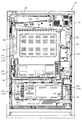
図2に示すように、遊技盤13は、正面視略正方形状に切削加工した木製のベース板60に、球案内用の多数の釘や風車、およびレール61,62、一般入賞口63、第1入球口64、第2入球口640、可変入賞装置65、作動入賞口660、可変表示装置ユニット80等を組み付けて構成され、その周縁部が内枠12の裏面側に取り付けられる。一般入賞口63、第1入球口64、第2入球口640、可変入賞装置65、作動入賞口660、可変表示装置ユニット80は、ルータ加工によってベース板60に形成された貫通穴に配設され、遊技盤13の前面側から木ネジ等により固定されている。また、遊技盤13の前面中央部分は、前面枠14の窓部14c(図1参照)を通じて内枠12の前面側から視認することができる。以下、主に図2を参照して、遊技盤13の構成について説明する。
As shown in FIG. 2, the
遊技盤13の前面には、帯状の金属板を略円弧状に屈曲加工して形成した外レール62が植立され、その外レール62の内側位置には外レール62と同様に帯状の金属板で形成した円弧状の内レール61が植立される。この内レール61と外レール62とにより遊技盤13の前面外周が囲まれ、遊技盤13とガラスユニット16(図1参照)とにより前後が囲まれることにより、遊技盤13の前面には、遊技球の挙動により遊技が行われる遊技領域が形成される。遊技領域は、遊技盤13の前面であって2本のレール61,62と円弧部材70とにより区画して形成される略円形状の領域(始動口等が配設され、発射された遊技球が流下する領域)である。また、遊技領域は、戻り球防止部材68を通過した遊技球がアウト口66や入賞口を通過するまでに流下する領域はすべて含まれる。
An
2本のレール61,62は、球発射ユニット112a(図8参照)から発射された遊技球を遊技盤13上部へ案内するために設けられたものである。外レール62の先端部分(図2の左上部)には、遊技球が入球可能な作動入賞口660が設けられている。この作動入賞口660は、遊技球が入球した場合に遊技者にとって有利な状態である大当たり状態(特別遊技状態)へと移行する。詳述すると、特別図柄(第1図柄)の抽選で大当たりと判定された場合に、この作動入賞口660への入球が有効とされる状態(大当たり待機状態)に設定される。なお、通常時は作動入賞口660へと遊技球が入球したとしても、何ら遊技に影響を与えることは無い。大当たり待機状態において、遊技者が遊技球を作動入賞口660に向けて発射することにより、遊技球が作動入賞口へと入球(入賞)して大当たりが開始される。なお、図2に示した通り、作動入賞口660の正面視左方向には、一定の回転速度で回転動作する回動部材670aが配設されている。この回動部材670aは、その回転位置に応じて作動入賞口660に向けて発射された遊技球が作動入賞口660の方向へ向かうのを妨げる配置と、妨げない配置とを取り得るため、回動部材670aが遊技球を妨げない配置となるタイミングを狙って遊技球を打ち出さなければ作動入賞口660へと遊技球を入球させること(大当たりを開始させること)ができない。よって、特別図柄の抽選で大当たりと判定された場合に、回動部材670aの配置を加味して遊技球を発射させることができるので、遊技者の遊技に対する興趣を向上させることができる。
The two
なお、作動入賞口660は、図2に示した通り、遊技球1個分よりも広く、2個分よりも狭い幅の流路(作動入賞口用流路)の終端に設けられている。この作動入賞口用流路は、少なくとも最大の勢い(発射強度)を含む所定範囲の発射強度(例えば、発射強度が95%〜100%の範囲)で発射された遊技球が届く(流入する)ように構成されている。このため、特別図柄の抽選で大当たりと判定され、大当たり待機状態になった場合には、作動入賞口660を狙う際に、単にハンドル51を可動し得る最大の範囲まで回転操作するだけで容易に作動入賞口660へと遊技球を入球させることができる。
As shown in FIG. 2, the
内レール61の先端部分には、返しゴム69が取り付けられている。所定の発射強度(例えば、発射強度が90%〜95%範囲)で発射された遊技球は、返しゴム69に当たって、勢いが減衰されつつ中央部側へ跳ね返される。また、内レール61の右下側の先端部と外レール62の右上側の先端部との間には、レール間を繋ぐ円弧を内面側に設けて形成された樹脂製の円弧部材70がベース板60に打ち込んで固定されている。
A
本パチンコ機10では、遊技球が第1入球口64、または第2入球口640のいずれかへ入球した場合に特別図柄(第1図柄)の抽選が行われ、遊技球が普通入球口67を通過した場合に普通図柄(第2図柄)の抽選が行われる。第1入球口64、または第2入球口640への入球に対して行われる特別図柄の抽選では、特別図柄の大当たりか否かの当否判定が行われると共に、特別図柄の大当たりと判定された場合にはその大当たり種別の判定も行われる。特別図柄の大当たりになると、パチンコ機10が特別遊技状態へ移行すると共に、通常時には閉鎖されている特定入賞口65aが所定時間(例えば、30秒経過するまで、或いは、遊技球が所定個数入賞するまで)開放され、その開放が大当たり種別に応じた回数(ラウンド数)繰り返される。その結果、その特定入賞口65aに多量の遊技球が入賞するので、通常時より多量の賞球の払い出しが行われる。特別図柄の大当たり種別としては、「大当たりA」〜「大当たりF」の6種類が設けられており、特別遊技状態の終了後には大当たり終了後の付加価値として、大当たり遊技の結果に応じた遊技上の価値(遊技価値)が遊技者に付与される。なお、「大当たりA〜C」の3種類は、遊技球が第1入球口64へと入球したことを契機として実行される特別図柄の抽選で大当たりとなった場合に決定され得る大当たり種別であり、「大当たりD〜F」の3種類は、遊技球が第2入球口640へと入球したことを契機として実行される特別図柄の抽選で大当たりとなった場合に決定され得る大当たり種別である。以降、説明の簡略化のため、遊技球が第1入球口64へと入球したことを契機として実行される特別図柄の抽選のことを第1特別図柄の抽選と称し、遊技球が第2入球口640へと入球したことを契機として実行される特別図柄の抽選のことを第2特別図柄の抽選と称する。
In this
特別図柄(第1図柄)の抽選が行われると、第1図柄表示装置37において特別図柄の変動表示が開始されて、所定時間(例えば、7秒〜90秒など)が経過した後に、抽選結果を示す特別図柄が停止表示される。第1図柄表示装置37において変動表示が行われている間に遊技球が第1入球口64、または第2入球口640へ入球すると、その入球回数は、入球口の種別毎にそれぞれ最大4回まで保留され、その保留球数が第1図柄表示装置37により示されると共に、第3図柄表示装置81においても示される。第1図柄表示装置37において変動表示が終了した場合に、第1入球口64、または第2入球口640についての保留球数が残っていれば、次の特別図柄の抽選が行われると共に、その抽選に応じた変動表示が開始される。
When the lottery of the special symbol (first symbol) is performed, the variable display of the special symbol is started on the first
一方、普通入球口67における遊技球の通過に対して行われる普通図柄の抽選では、普通図柄の当たりか否かの当否判定が行われる。普通図柄の当たりになると、所定時間(例えば、0.2秒または1秒)だけ第2入球口640に付随する電動役物640aが開放位置に可変されることで第2入球口640が開放される。なお、通常時は、電動役物640aが閉鎖位置に配設されているため、第2入球口640が閉鎖されている。よって、正面視上方から第2入球口640に向かって流下してきた球は、電動役物640aに阻まれることにより第2入球口640へと入球することが不可能(困難)となる。一方、普通図柄の当たりとなった場合は、電動役物640aが開放されることにより、第2入球口640に向かって流下してきた球が第2入球口640へ入球し易くなり、その結果、第2特別図柄の抽選が行われ易くなる。
On the other hand, in the lottery of the normal symbol performed for the passage of the game ball at the
また、普通図柄(第2図柄)の抽選が行われると、第2図柄表示装置83において普通図柄の変動表示が開始されて、所定時間(例えば、3秒や30秒など)が経過した後に、抽選結果を示す普通図柄が停止表示される。第2図柄表示装置83において変動表示が行われている間に遊技球が普通入球口67を通過すると、その通過回数は最大4回まで保留され、その保留球数が第1図柄表示装置37により表示されると共に、第2図柄保留ランプ84においても示される。第2図柄表示装置83において変動表示が終了した場合に、普通入球口67についての保留球数が残っていれば、次の普通図柄の抽選が行われると共に、その抽選に応じた変動表示が開始される。
Further, when the lottery of the normal symbol (second symbol) is performed, the variable display of the normal symbol is started on the second
上述したように、特別図柄の大当たり種別としては、「大当たりA」〜「大当たりF」の6種類が設けられている。 As described above, as the jackpot type of the special symbol, six types of "big hit A" to "big hit F" are provided.
「大当たりA」になると、ラウンド数が8ラウンドの特別遊技状態(8ラウンド大当たり)となる。一方、「大当たりB」、または「大当たりC」になると、ラウンド数が5ラウンドの特別遊技状態(5ラウンド大当たり)となり、「大当たりD」になると、ラウンド数が16ラウンドの特別遊技状態(16ラウンド大当たり)となり、「大当たりE」、「大当たりF」になると、ラウンド数が10ラウンドの特別遊技状態(10ラウンド大当たり)となる。更に、「大当たりA」、「大当たりB」、「大当たりD」、「大当たりE」になった場合は、大当たり終了後に特別図柄の高確率状態(特別図柄の確変中)へ移行する。また、特別図柄の高確率状態が付与された場合には、普通図柄の当たり確率もアップする(普通図柄の時短状態が付与される)。特別図柄の高確率状態、および普通図柄の時短状態は、大当たり終了後から次に大当たりとなるまで継続する。一方、「大当たりC」、または「大当たりF」になると、大当たり終了後に普通図柄の時短状態が付与されるものの、特別図柄の高確率状態は付与されない。この「大当たりC」、または「大当たりF」の終了後に付与される普通図柄の時短状態は、特別図柄の抽選が100回実行されることにより終了する。 When it becomes "big hit A", it becomes a special game state (8 rounds big hit) with 8 rounds. On the other hand, when it becomes "big hit B" or "big hit C", it becomes a special game state (5 rounds big hit) with 5 rounds, and when it becomes "big hit D", it becomes a special game state (16 rounds) with 16 rounds. When it becomes "big hit E" and "big hit F", the number of rounds becomes a special game state of 10 rounds (10 round big hit). Further, when "Big hit A", "Big hit B", "Big hit D", and "Big hit E" are reached, the probability shifts to the high probability state of the special symbol (during the probability change of the special symbol) after the jackpot ends. In addition, when the high probability state of the special symbol is given, the hit probability of the normal symbol is also increased (the time saving state of the normal symbol is given). The high-probability state of the special symbol and the time-saving state of the normal symbol continue from the end of the big hit until the next big hit. On the other hand, when it becomes "big hit C" or "big hit F", the time saving state of the normal symbol is given after the big hit ends, but the high probability state of the special symbol is not given. The time saving state of the normal symbol given after the end of the "big hit C" or the "big hit F" ends when the special symbol lottery is executed 100 times.
ここで、「特別図柄の高確率状態」とは、特別図柄の大当たり確率がアップした状態、いわゆる「特別図柄の高確率状態」(特別図柄の確変状態)をいい、換言すれば、特別遊技状態(大当たり)へ移行し易い遊技の状態のことである。対して、「特別図柄の高確率状態」でない場合を「特別図柄の低確率状態」といい、これは特別図柄の確変状態よりも大当たり確率が低い状態、即ち、特別図柄の大当たり確率が通常の状態(特別図柄の低確率状態)のことを示す。また、「普通図柄の時短状態」(普通図柄の高確率状態)とは、普通図柄の当たり確率がアップして、第2入球口640へ遊技球が入球し易い遊技状態のことをいう。これ対して、「普通図柄の時短状態」でない時を「普通図柄の通常状態」(普通図柄の低確率状態)といい、これは普通図柄の当たり確率が通常の状態、即ち、時短中よりも当たり確率が低い状態のことを示す。
Here, the "high probability state of the special symbol" means a state in which the jackpot probability of the special symbol is increased, that is, a so-called "high probability state of the special symbol" (probability change state of the special symbol), in other words, a special gaming state. It is a state of the game in which it is easy to shift to (big hit). On the other hand, the case where it is not the "high probability state of the special symbol" is called the "low probability state of the special symbol", which means that the jackpot probability is lower than the probability variation state of the special symbol, that is, the jackpot probability of the special symbol is normal. Indicates a state (low probability state of a special symbol). In addition, the "time saving state of the normal symbol" (high probability state of the normal symbol) means a gaming state in which the hit probability of the normal symbol is increased and the game ball can easily enter the
上述したように、本実施形態における特別図柄の大当たりでは、大当たりの種別に応じて大当たり時のラウンド数を異ならせている。これに対して、全ての大当たり種別でラウンド数を共通(例えば、全て5ラウンド)としても良い。また、本実施形態では、大当たり後に付与された「特別図柄の確変状態」が、次に大当たりとなるまで継続する構成としたが、これに限られるものではない。例えば、「特別図柄の確変状態」が継続する期間を、特別図柄の抽選回数が所定回数(例えば、100回)実行されるまでの間に限定する構成としてもよい。この場合において、「特別図柄の確変状態」となる抽選回数と、「普通図柄の時短状態」となる抽選回数とを異ならせてもよい。また、大当たりの種別に応じて、抽選回数を可変させる構成としてもよい。 As described above, in the jackpot of the special symbol in the present embodiment, the number of rounds at the time of jackpot is different depending on the type of jackpot. On the other hand, the number of rounds may be the same for all jackpot types (for example, all 5 rounds). Further, in the present embodiment, the "probability change state of the special symbol" given after the big hit is continued until the next big hit, but the present invention is not limited to this. For example, the period in which the "probability change state of the special symbol" continues may be limited to the period until the number of lottery of the special symbol is executed a predetermined number of times (for example, 100 times). In this case, the number of lottery that is in the "probability change state of the special symbol" and the number of lottery that is in the "time saving state of the normal symbol" may be different. In addition, the number of lottery may be changed according to the type of jackpot.
本パチンコ機10では、電源などの投入等により初期設定が行われると、必ず「特別図柄の低確率状態」、および「普通図柄の通常状態」に設定される。そして、「大当たりA」、「大当たりB」、「大当たりD」、「大当たりE」の何れかになった場合は、「特別図柄の低確率状態」から「特別図柄の確変状態」へ移行すると共に、「普通図柄の通常状態」から「普通図柄の時短状態」へ移行する。この場合、設定された「特別図柄の確変状態」と、「普通図柄の時短状態」とは、次に大当たりとなるまで継続する。一方、「大当たりC」、または「大当たりF」になると、「特別図柄の低確率状態」、且つ「普通図柄の時短状態」に移行する。以降、説明の簡略化のため、大当たりの終了後に「特別図柄の確変状態」、且つ「普通図柄の時短状態」が付与される大当たり(「大当たりA」、「大当たりB」、「大当たりD」、「大当たりE」)のことを、「確変大当たり」と称する。一方、大当たりの終了後に100回の「普通図柄の時短状態」のみが付与される大当たり(「大当たりC」、「大当たりF」)のことを、「通常大当たり」と称する。
In the
遊技盤13の正面視左側下部(図2の左側下部)には、発光手段である複数の発光ダイオード(以下、「LED」と略す。)37aと7セグメント表示器37bとが設けられた第1図柄表示装置37が配設されている。第1図柄表示装置37は、後述する主制御装置110で行われる各制御に応じた表示がなされるものであり、主にパチンコ機10の遊技状態の表示が行われる。複数のLED37aは、第1入球口64への入球(始動入賞)に伴って行われる特別図柄の抽選が実行中であるか否かを点灯状態により示すことによって変動表示を行ったり、変動終了後の停止図柄として、その特別図柄の抽選結果に応じた特別図柄(第1図柄)を点灯状態により示したり、第1入球口64、または第2入球口640に入球された遊技球のうち変動が未実行である遊技球(保留球)の数である保留球数を点灯状態により示すものである。
A first unit is provided with a plurality of light emitting diodes (hereinafter abbreviated as "LED") 37a and a 7-
この第1図柄表示装置37において特別図柄(第1図柄)の変動表示が行われている間に遊技球が第1入球口64、または第2入球口640へ入球した場合、その入球回数は最大4回まで保留され、その保留球数は第1図柄表示装置37により示されると共に、第3図柄表示装置81においても示される。なお、本実施形態においては、第1入球口64、および第2入球口640への入球は、それぞれ最大4回まで保留されるように構成したが、最大保留回数は4回に限定されるものでなく、3回以下、又は、5回以上の回数(例えば、8回)に設定しても良い。
If the game ball enters the
7セグメント表示器37bは、大当たり中のラウンド数やエラー表示を行うものである。なお、LED37aは、それぞれのLEDの発光色(例えば、赤、緑、青)が異なるよう構成され、その発光色の組み合わせにより、少ないLEDでパチンコ機10の各種遊技状態(特別図柄の高確率状態や、普通図柄の時短中など)を表示することができる。また、LED37aには、変動終了後の停止図柄として特別図柄の抽選結果が大当たりであるか否かが示されるだけでなく、大当たりである場合はその大当たり種別(大当たりA〜Fに応じた特別図柄(第1図柄)が示される。
The 7-
また、遊技領域には、遊技球が入賞することにより5個から15個の遊技球が賞球として払い出される複数の一般入賞口63が配設されている。また、遊技領域の中央部分には、可変表示装置ユニット80が配設されている。可変表示装置ユニット80には、液晶ディスプレイ(以下単に「表示装置」と略す。)で構成された第3図柄表示装置81と、LEDで構成された第2図柄表示装置83とが設けられている。この可変表示装置ユニット80には、第3図柄表示装置81の外周を囲むようにして、センターフレーム86が配設されている。
Further, in the game area, a plurality of general winning
第3図柄表示装置81は、第1図柄表示装置37の表示に応じた装飾的な表示を行うものである。例えば、第1入球口64、または第2入球口640へ遊技球が入球(始動入賞)すると、それをトリガとして、第1図柄表示装置37において特別図柄(第1図柄)の変動表示が実行される。更に、第3図柄表示装置81では、その特別図柄の変動表示に同期して、その特別図柄の変動表示に対応する第3図柄の変動表示が行われる。
The third
第3図柄表示装置81は、8インチサイズの大型の液晶ディスプレイで構成されるものであり、後述する表示制御装置114によって表示内容が制御されることにより、例えば左、中及び右の3つの図柄列が表示される。各図柄列は複数の図柄によって構成され、これらの図柄が図柄列毎に縦スクロールして第3図柄表示装置81の表示画面上にて第3図柄が可変表示されるようになっている。本実施形態では、主制御装置110の制御に伴った遊技状態の表示が第1図柄表示装置37で行われるのに対して、第3図柄表示装置81はその第1図柄表示装置37の表示に応じた装飾的な表示が行われる。なお、表示装置に代えて、例えば、リール等を用いて第3図柄表示装置81を構成するようにしても良い。
The third
ここで、図6を参照して、第3図柄表示装置81の表示内容について説明する。図7は、第3図柄表示装置81の表示画面を説明するための図面であり、図6(a)は、表示画面の領域区分設定と有効ライン設定とを模式的に示した図であり、図6(b)は、実際の表示画面を例示した図である。
Here, the display contents of the third
第3図柄は、「1」から「9」の数字を付した9種類の主図柄により構成されている。各主図柄は、「1」から「9」の数字を模して構成されている。各主図柄は、木箱よりなる後方図柄の上に「1」から「9」の数字を付して構成され、そのうち奇数番号(1,3,5,7,9)を付した主図柄は、木箱の前面ほぼ一杯に大きな数字が付加されている。これに対し、偶数番号(2,4,6,8)を付した主図柄は、木箱の前面ほぼ一杯にかんな、風呂敷、ヘルメット等のキャラクタを模した付属図柄が付加されており、付属図柄の右下側に偶数の数字が緑色で小さく、且つ、付属図柄の前側に表示されるように付加されている。 The third symbol is composed of nine types of main symbols with numbers "1" to "9". Each main symbol is configured by imitating the numbers "1" to "9". Each main symbol is composed of a rear symbol consisting of a wooden box with numbers from "1" to "9", of which the main symbols with odd numbers (1,3,5,7,9) are , A large number is added to almost the front of the wooden box. On the other hand, the main symbols with even numbers (2, 4, 6, 8) have attached symbols that imitate characters such as planes, furoshiki, helmets, etc. that are almost full on the front of the wooden box. Even numbers are small in green on the lower right side of, and are added so that they are displayed on the front side of the attached symbol.
また、本実施形態のパチンコ機10においては、後述する主制御装置110(図8参照)により行われる特別図柄の抽選結果が大当たりであった場合に、同一の主図柄が揃う変動表示が行われ、その変動表示が終わった後に大当たりが発生するよう構成されている。一方、特別図柄の抽選結果が外れであった場合は、同一の主図柄が揃わない変動表示が行われる。
Further, in the
例えば、特別図柄の抽選結果が確変大当たり(「大当たりA」、「大当たりB」、「大当たりD」、「大当たりE」のいずれか)であれば、「1」〜「9」のいずれかが付加された主図柄が揃う変動表示が行われる。また、通常大当たり(「大当たりC」、または「大当たりF」)であれば、偶数番号である「0,2,4,6,8」が付加された主図柄が揃う変動表示が行われる。即ち、奇数番号である「1,3,5,7,9」が付加された主図柄が揃う変動表示は、確変大当たりでのみ実行される可能性がある。確変大当たりの場合でも、偶数の数字が付された主図柄が揃う変動表示が行われる可能性がある構成とすることにより、偶数の数字が付された主図柄が揃った場合にも、確変大当たりであることを期待して大当たり中の遊技を行わせることができる。一方、特別図柄の抽選結果が外れであれば、同一番号の主図柄が揃わない変動表示が行われる。なお、確変大当たりにおいて、偶数の数字が付された主図柄が揃う変動表示が行われる割合は、例えば、60%に設定される。また、偶数の数字が付された主図柄が揃う変動表示によって確変大当たりが開始された場合には、大当たりの所定期間(例えば、5ラウンドのラウンド期間中)において、確変大当たりであったことを報知する演出が実行される。 For example, if the lottery result of the special symbol is a probabilistic jackpot (one of "big hit A", "big hit B", "big hit D", and "big hit E"), one of "1" to "9" is added. A variable display is performed in which the main symbols are aligned. Further, in the case of a normal jackpot (“big hit C” or “big hit F”), a variable display is performed in which the main symbols to which the even numbers “0, 2, 4, 6, 8” are added are aligned. That is, the variable display in which the main symbols to which the odd numbers "1, 3, 5, 7, 9" are added may be executed only in the probability variation jackpot. Even in the case of a probabilistic jackpot, even if the main symbols with even numbers are aligned, the variable display may be performed so that the main symbols with even numbers are aligned. It is possible to play a game during a big hit with the expectation that it will be. On the other hand, if the lottery result of the special symbol is out of order, a variable display is performed in which the main symbols having the same number are not aligned. In addition, in the probability variation jackpot, the ratio of the variable display in which the main symbols with even numbers are aligned is set to, for example, 60%. In addition, when a probabilistic jackpot is started by a variable display in which the main symbols with even numbers are aligned, it is notified that the probabilistic jackpot was a probabilistic jackpot during a predetermined period of the jackpot (for example, during a round period of 5 rounds). The production to be performed is executed.
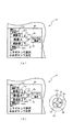
図6(a)に示すように、第3図柄表示装置81の表示画面は、大きくは上下に2分割され、下側の2/3が第3図柄を変動表示する主表示領域Dm、それ以外の上側の1/3が予告演出、キャラクタおよび保留球数などを表示する副表示領域Dsとなっている。
As shown in FIG. 6A, the display screen of the third
主表示領域Dmは、左・中・右の3つの表示領域Dm1〜Dm3に区分けされており、その3つの表示領域Dm1〜Dm3に、それぞれ3つの図柄列Z1,Z2,Z3が表示される。各図柄列Z1〜Z3には、上述した第3図柄が規定の順序で表示される。即ち、各図柄列Z1〜Z3には、数字の昇順または降順に主図柄が配列され、図柄列Z1〜Z3毎に周期性をもって上から下へとスクロールして変動表示が行われる。特に、左図柄列Z1においては主図柄の数字が降順に現れるように配列され、中図柄列Z2及び右図柄列Z3においては主図柄の数字が昇順に現れるように配列されている。 The main display area Dm is divided into three display areas Dm1 to Dm3 on the left, middle, and right, and three symbol columns Z1, Z2, and Z3 are displayed in the three display areas Dm1 to Dm3, respectively. In each of the symbol rows Z1 to Z3, the above-mentioned third symbols are displayed in a specified order. That is, the main symbols are arranged in the ascending or descending order of the numbers in the symbol rows Z1 to Z3, and the symbol rows Z1 to Z3 are scrolled from top to bottom with periodicity to perform variable display. In particular, in the left symbol row Z1, the numbers of the main symbols are arranged so as to appear in descending order, and in the middle symbol row Z2 and the right symbol row Z3, the numbers of the main symbols appear in ascending order.
また、主表示領域Dmには、図柄列Z1〜Z3毎に上・中・下の3段に第3図柄が表示される。この主表示領域Dmの中段部が有効ラインL1として設定されており、毎回の遊技に際して、左図柄列Z1→右図柄列Z3→中図柄列Z2の順に、有効ラインL1上に第3図柄が停止表示される。この停止表示状態は最低1秒間保持される。このように、停止した第3図柄を一定期間(1秒以上)表示させておくことで、遊技者が大当たりに対応する第3図柄の組み合わせであるか否か(特別図柄の抽選結果が大当たりであるか否か)を見落としてしまうことを抑制することができる。また、第3図柄の停止時に有効ラインL1上に大当たり図柄の組合せ(本実施形態では、同一の主図柄の組合せ)が揃えば、大当たりが確定し、大当たり待機状態を示す待機状態演出が表示される。この待機状態演出の詳細については、図7を参照して後述する。また、大当たり待機状態の間に遊技球を作動入賞口660に入球(入賞)させることにより、大当たりが開始され、大当たり動画(オープニング演出)が表示される。
Further, in the main display area Dm, the third symbol is displayed in the upper, middle, and lower three rows for each of the symbol rows Z1 to Z3. The middle part of this main display area Dm is set as the effective line L1, and the third symbol stops on the effective line L1 in the order of left symbol row Z1 → right symbol row Z3 → middle symbol row Z2 in each game. Is displayed. This stop display state is held for at least 1 second. By displaying the stopped 3rd symbol for a certain period of time (1 second or more) in this way, whether or not the player is a combination of the 3rd symbols corresponding to the jackpot (the lottery result of the special symbol is a jackpot). It is possible to prevent overlooking (whether or not there is). Further, if the combination of jackpot symbols (in the present embodiment, the same combination of main symbols) is aligned on the effective line L1 when the third symbol is stopped, the jackpot is confirmed and the standby state effect indicating the jackpot standby state is displayed. To. Details of this standby state effect will be described later with reference to FIG. 7. Further, by making the game ball enter (win) the
また、停止表示された第3図柄の組み合わせが外れに対応する組み合わせであって、保留球が存在する場合は、1秒間の停止表示後に、保留球に基づく抽選に対応する変動表示が開始される。なお、複数の保留球が存在する場合は、時間的に最も古い入球に対応する保留球に基づいて抽選が実行される。 Further, if the combination of the third symbols displayed as stopped is a combination corresponding to the detachment and there is a reserved ball, the variable display corresponding to the lottery based on the reserved ball is started after the stop display for 1 second. .. If there are a plurality of reserved balls, the lottery is executed based on the reserved balls corresponding to the oldest incoming balls in time.
一方、保留球が存在しない状態で、特別図柄の外れに対応する組み合わせの第3図柄が1秒間停止表示された場合は、その後も第3図柄が停止表示された状態が継続する。この状態は、所定時間(例えば、15秒)が経過するか、または、第1入球口64に対して新たに遊技球が入球するまで継続する。そして、第3図柄が停止表示されてから所定時間(例えば、15秒)が経過した場合は、遊技が実行されていないことを示すデモ演出が表示される。遊技者が遊技球を所定時間(例えば、15秒)連続して発射させているにも関わらず、第1入球口64への入球が無いという状況は稀であり、第3図柄が停止表示された状態が所定時間(例えば、15秒)継続する場合の多くは、遊技者が遊技を辞めたことで、パチンコ機10による遊技が全く行われていないことに起因する。よって、本実施形態のパチンコ機10では、第3図柄が停止表示されてから所定時間(例えば、15秒)が経過した時点で、遊技者が遊技を行っていないと判断し、デモ演出を開始する。これにより、遊技を開始するためにパチンコ機10を選択しようとしている遊技者が、デモ演出の表示の有無に基づいて遊技が行われているか否かを容易に判断することができる。一方、所定時間(例えば、15秒)が経過する前に第1入球口64に対して新たに遊技球が入球した場合は、その新たな入球に対応する第3図柄の変動表示が実行される。
On the other hand, when the third symbol of the combination corresponding to the deviation of the special symbol is stopped and displayed for 1 second in the state where the holding ball does not exist, the state in which the third symbol is stopped and displayed continues thereafter. This state continues until a predetermined time (for example, 15 seconds) elapses or a new game ball enters the first
副表示領域Dsは、主表示領域Dmよりも上方に横長に設けられており、さらに左右方向に3つの小領域Ds1〜Ds3に等区分されている。このうち、小領域Ds1は、第1入球口64、および第2入球口640に入球された遊技球のうち変動が未実行である遊技球(保留球)の数である保留球数を表示する領域であり、小領域Ds2およびDs3は、予告演出画像を表示する領域である。
The sub-display area Ds is provided horizontally above the main display area Dm, and is further divided into three small areas Ds1 to Ds3 in the left-right direction. Of these, the small area Ds1 is the number of reserved balls, which is the number of game balls (reserved balls) that have not been changed among the game balls that have been entered into the
実際の表示画面では、図4(b)に示すように、主表示領域Dmに第3図柄の主図柄が合計9個表示される。副表示領域Dsにおいては、右の小領域Ds3に動画が表示され、通常より大当たりへ遷移し易い状態であることが遊技者に示唆される。中央の小領域Ds2では、通常は、所定のキャラクタ710(本実施形態ではハチマキを付けた少年)が所定動作をし、時として所定動作とは別の特別な動作をしたり、別のキャラクタが現出する等して予告演出が行われる。 On the actual display screen, as shown in FIG. 4B, a total of nine main symbols of the third symbol are displayed in the main display area Dm. In the sub-display area Ds, the moving image is displayed in the small area Ds3 on the right, suggesting to the player that the transition to the jackpot is easier than usual. In the central small area Ds2, a predetermined character 710 (a boy with a headband in this embodiment) usually performs a predetermined action, and sometimes a special action different from the predetermined action or another character performs a predetermined action. A notice production will be performed by appearing.
一方、第3図柄表示装置81(第1図柄表示装置37)にて変動表示が行われている間に遊技球が第1入球口64、または第2入球口640へ入球した場合、その入球回数は入球口の種別毎に、それぞれ最大4回まで保留され、その保留球数は第1図柄表示装置37により示されると共に、副表示領域Dsの小領域Ds1においても示される。小領域Ds1には、保留球数1球につき1つの保留球数図柄が表示され、その保留球数図柄の表示数に応じて、保留球数が表示される。即ち、小領域Ds1に1つの保留球数図柄が表示されている場合は、保留球数が1球であることを示し、4つの保留球数図柄が表示されている場合は、保留球数が4球であることを示す。また、小領域Ds1に保留球数図柄が表示されていない場合は、保留球数が0球である、即ち、保留球が存在しないことを示す。なお、小領域Ds1のうち、左半分には、第1入球口64への入球に基づく保留球数を示す保留球数図柄を表示し、小領域Ds2のうち、右半分には、第2入球口640への入球に基づく保留球数を示す保留球数図柄を表示する構成としている。図6(b)の例では、小領域Ds1の左半分に4つの保留球数図柄が表示されている一方で、右半分には保留球数図柄が1つも表示されていないので、第1特別図柄の保留球が4つ存在するが、第2特別図柄の保留球は0個となっている状態を示している。
On the other hand, when the game ball enters the first
なお、本実施形態においては、第1入球口64、および第2入球口640への入球は、それぞれ最大4回まで保留されるように構成したが、最大保留球数は4回に限定されるものでなく、3回以下、又は、5回以上の回数(例えば、8回)に設定しても良い。また、小領域Ds1における保留球数図柄の表示に代えて、保留球数を第3図柄表示装置81の一部に数字で、或いは、4つに区画された領域を保留球数分だけ異なる態様(例えば、色や点灯パターン)にして表示するようにしても良い。また、第1図柄表示装置37により保留球数が示されるので、第3図柄表示装置81に保留球数を表示させないものとしてもよい。更に、可変表示装置ユニット80に、保留球数を示す保留ランプを最大保留数分の4つ設け、点灯状態の保留ランプの数に応じて、保留球数を表示するものとしてもよい。
In the present embodiment, the first
第2図柄表示装置83は、遊技球が普通入球口67を通過することに伴って行われる普通図柄の抽選が実行中であるか否かを点灯状態により示すことによって変動表示を行ったり、変動終了後の停止図柄として、その普通図柄の抽選結果に応じた普通図柄(第2図柄)を点灯状態により示したりするものである。
The second
より具体的には、第2図柄表示装置83では、遊技球が左右いずれかの普通入球口67を通過する毎に、普通図柄(第2図柄)としての「○」の図柄と「×」の図柄とを交互に点灯させる変動表示が行われる。パチンコ機10は、第2図柄表示装置83における変動表示が所定図柄(本実施形態においては「○」の図柄)で停止すると、第2入球口640に付随する電動役物640aが所定時間だけ作動状態となり(開放される)、その結果、第2入球口640に遊技球が入り易い状態となるように構成されている。遊技球が普通入球口67を通過した通過回数は最大4回まで保留され、その保留球数が上述した第1図柄表示装置37により表示されると共に第2図柄保留ランプ84においても点灯表示される。第2図柄保留ランプ84は、最大保留数分の4つ設けられ、第3図柄表示装置81の下方に左右対称に配設されている。
More specifically, in the second
なお、普通図柄(第2図柄)の変動表示は、本実施形態のように、第2図柄表示装置83において複数のランプの点灯と非点灯を切り換えることにより行うものの他、第1図柄表示装置37及び第3図柄表示装置81の一部を使用して行うようにしても良い。同様に、第2図柄保留ランプ84の点灯を第3図柄表示装置81の一部で行うようにしても良い。また、普通入球口67における遊技球の通過は、第1入球口64や第2入球口640と同様に、最大保留球数は4回に限定されるものでなく、3回以下、又は、5回以上の回数(例えば、8回)に設定しても良い。また、第1図柄表示装置37により保留球数が示されるので、第2図柄保留ランプ84により点灯表示を行わないものとしても良い。
The variation display of the normal symbol (second symbol) is performed by switching the lighting and non-lighting of a plurality of lamps in the second
可変表示装置ユニット80の下方には、遊技球が入球し得る第1入球口64が配設されている。この第1入球口64へ遊技球が入球すると遊技盤13の裏面側に設けられる第1入球口スイッチ(図示せず)がオンとなり、その第1入球口スイッチのオンに起因して主制御装置110で第1特別図柄の抽選がなされ、その抽選結果に応じた表示が第1図柄表示装置37のLED37aで示される。また、第1入球口64は、遊技球が入球すると5個の賞球が払い出される入賞口の1つにもなっている。なお、この第1入球口64は、可変表示装置ユニット80の左側の流路を流下した遊技球(左打ちされた遊技球)の方が、可変表示装置ユニット80の右側の流路を流下した遊技球(右打ちされた遊技球)に比べて入球し易くなるように、釘等が配置されている。
Below the variable
可変表示装置ユニット80の正面視右下側には、遊技球が入球し得る第2入球口640が配設されている。この第2入球口640へ遊技球が入球すると遊技盤13の裏面側に設けられる第2入球口スイッチ(図示せず)がオンとなり、その第2入球口スイッチのオンに起因して主制御装置110で第2特別図柄の抽選がなされ、その抽選結果に応じた表示が第1図柄表示装置37のLED37aで示される。また、第2入球口640は、遊技球が入球すると5個の賞球が払い出される入賞口の1つにもなっている。図2に示した通り、第2入球口640は、遊技盤13の右側に設けられているため、基本的に可変表示装置ユニット80の右方向に設けられた流路を流下した遊技球のみが入球する。
On the lower right side of the variable
第2入球口640の正面視左下方向には、右可変入賞装置65が配設されており、その略中央部分に横長矩形状の右特定入賞口65aが設けられている。また、右可変入賞装置65の正面視左下方向には、左可変入賞装置650が配設されている。この左可変入賞装置650は、左特定入賞口650aを覆う横長矩形状の開閉板と、その開閉板の下辺を軸として前方側に開閉駆動するための大開放口ソレノイド(図示せず)とを備えている。開閉板は、通常時は、遊技球が入賞できない閉状態になっている。開閉板の閉状態においては、開閉板と遊技盤13とが同一平面上となるように閉鎖されるため、遊技球が開閉板の手前側を通過可能となる。また、開閉板が前面下側に傾倒することで、遊技球が左特定入賞口650aに入賞しやすい開状態を一時的に形成する。パチンコ機10においては、主制御装置110で行われる特別図柄の抽選が大当たりとなると、所定時間(変動時間)が経過した後に、大当たりの停止図柄となるよう第1図柄表示装置37のLED37aを点灯させると共に、その大当たりに対応した第3図柄の停止図柄を第3図柄表示装置81に表示させて、大当たりの確定(大当たりの権利を得たこと)が示される。そして、大当たりが確定したことで移行した大当たり待機状態において、遊技球を作動入賞口660へと入球させることで、通常時より多量の賞球の払い出しが行われる特別遊技状態に遊技状態が遷移する。この特別遊技状態として、通常時には閉鎖されている右特定入賞口65a、および左特定入賞口650aが、所定時間(例えば、30秒経過するまで、或いは、遊技球が所定個数入賞するまで)開放される。即ち、通常時は右特定入賞口65aを閉鎖している開閉扉65f1が、大当たり(特別遊技状態)の1ラウンド目となることにより開放され、右特定入賞口65aへと球が入球可能となる。右特定入賞口65aに遊技球が1個入球する毎に10個の賞球が付与される。加えて、大当たり(特別遊技状態)の2ラウンド目以降の各ラウンドでは、左特定入賞口650aが開放されて入球可能となる。左特定入賞口650aも、右特定入賞口65aと同様に、遊技球が1個入球する毎に10個の賞球が付与される。
A right variable winning
なお、右特定入賞口65a、左特定入賞口650a、および上述した第2入球口640は、可変表示装置ユニット80の右側の流路を流下した遊技球(右打ちされた遊技球)が入球可能(入球容易)となる位置に配置されている。言い換えれば、可変表示装置ユニット80の左側の流路を流下した遊技球が入球不可能(入球困難)となる位置に配置されている。よって、遊技者が大当たり中に賞球の払い出しを受ける(利益を得る)ためには、遊技球を右打ちすればよい。ここで、図2に示した通り、右可変入賞装置65は、正面視左下方向に下る向きに若干傾斜した状態で配設されている。これにより、開閉扉65f1が閉鎖された状態で遊技者が右打ちを行い、遊技球が右可変入賞装置65の上面に到達した場合に、その到達した遊技球を右可変入賞装置65の傾斜に沿って正面視左下方向へと流下させてアウト口66に入球させることができる。よって、右打ちにより発射された遊技球が右可変入賞装置65の上部(開閉扉65f1の上面)に滞留してしまうことを防止(抑制)することができる。なお、図2に示した通り、左可変入賞装置650は、右可変入賞装置65の左下に配設されているので、左特定入賞口650aが開放されている場合には、右可変入賞装置65の傾斜に沿って正面視左下方向へと流下した遊技球が左特定入賞口650aへと入球する。
The right specific winning
本第1実施形態におけるパチンコ機10では、大当たりの各ラウンドが終了する(開放された右特定入賞口65a、または左特定入賞口650aを、再度閉鎖する)条件を、大当たりのラウンド(開放される特定入賞口の種別)に応じて異ならせている。具体的には、1ラウンド目(右特定入賞口65aが開放されるラウンド)は、開閉扉65f1が開放されてから30秒間が経過するか、または、2個以上の遊技球が右特定入賞口65aに入賞(入球)した場合に開閉扉65f1が閉鎖されて1ラウンド目が終了される。一方、大当たりの2ラウンド目以降の各ラウンド(左特定入賞口650aが開放されるラウンド)においては、左特定入賞口650aが開放されてから30秒間が経過するか、または、10個以上の遊技球が左特定入賞口650aへと入賞した場合に左特定入賞口650aが閉鎖されてラウンドが終了される。
In the
なお、右可変入賞装置65において、右特定入賞口65aに対する遊技球の入球を検知するためのセンサは、右可変入賞装置65の内部に設けられている。よって、右特定入賞口65aへと遊技球が入賞(入球)してから、入球が検知されるまでにはタイムラグが生じる。より具体的には、遊技球が右特定入賞口65aへと入球してから、実際に入球数がカウントされるまでには約0.5秒間を要する。つまり、ラウンドの終了条件が成立する個数となる遊技球が右特定入賞口65aに入球してから開閉扉65f1が閉鎖されるまでには約0.5秒間を要する。よって、この0.5秒間の間に遊技球を追加で入球させることができれば、通常(ラウンドの終了上限が成立する個数のみが入賞した場合)よりも多くの賞球を獲得することができる。本第1実施形態では、1ラウンド(右特定入賞口65aが開放されるラウンド)において、ラウンドの終了条件となる個数以上の遊技球を遊技者が意図的に右特定入賞口65aに対して入球させることができる構成としている。以降、説明の簡略化のため、各ラウンドで規定されている上限の入賞個数(入球個数)を上回る個数の遊技球が特定入賞口65aに入賞(入球)することを、「オーバー入賞」と称する。
In the right variable winning
詳細については図4、および図5を参照して後述するが、本第1実施形態では、オーバー入賞を発生させ易くするために、遊技球が開閉扉65f1の上面に到達してから、開閉扉65f1の上面を通過しきるまでの期間が長くなるように開閉扉65f1の上面を構成している。このように構成することで、1の遊技球が開閉扉65f1の上面を流下している間に、複数の遊技球を追加して開閉扉65f1の上面に到達させ易くなる。よって、大当たり待機状態において、より多くの遊技球が開閉扉65f1の上面を流下しているタイミングで、作動入賞口660へと遊技球を入球させて大当たりを開始させる(開閉扉65f1を開放させる)ことにより、開閉扉65f1の上面を流下中の全ての遊技球を開放された右特定入賞口65aへと入球させることができる。上述した通り、大当たりの1ラウンド目では特定入賞口65aに対する2個以上の入賞(入球)を検出した場合に終了する。しかしながら、大当たりの開始前に3個以上の遊技球を開閉扉65f1の上面に到達させた状態で大当たりの1ラウンド目を開始させることができれば、3個以上の遊技球を右特定入賞口65aへと入賞(入球)させて、本来(2個分の入賞に対する賞球)よりも多くの賞球を獲得することができる。よって、作動入賞口660へと遊技球を入球させるタイミングに応じて、遊技者が大当たりの1ラウンド目に獲得可能な賞球数に影響を与える遊技性を提供することができるので、大当たり待機状態中における遊技をより楽しませることができる。なお、大当たり待機状態の間に、開閉扉65f1へと遊技球を到達させるには、作動入賞口660へと遊技球が入球しない(作動入賞口用流路(図2参照)へと遊技球が流入しない)程度の発射強度(95%未満の発射強度)で右打ちを行えばよい。
Details will be described later with reference to FIGS. 4 and 5, but in the first embodiment, in order to facilitate over-winning, the opening / closing door is opened after the game ball reaches the upper surface of the opening / closing door 65f1. The upper surface of the opening / closing door 65f1 is configured so that the period until the door passes through the upper surface of the 65f1 is long. With this configuration, it becomes easy to add a plurality of game balls to reach the upper surface of the opening / closing door 65f1 while one game ball is flowing down the upper surface of the opening / closing door 65f1. Therefore, in the jackpot standby state, at the timing when more game balls are flowing down the upper surface of the opening / closing door 65f1, the game balls are entered into the
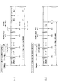
次に、図4、および図5を参照して、開閉扉65f1の上面の構造について説明する。まず、図4(a)は、開閉扉65f1が閉鎖された状態における可変入賞装置65の正面斜視図であり、図4(b)は、開閉扉65f1が開放された状態における可変入賞装置65の正面斜視図である。
Next, the structure of the upper surface of the opening / closing door 65f1 will be described with reference to FIGS. 4 and 5. First, FIG. 4A is a front perspective view of the variable winning
図4(a)に示した通り、開閉扉65f1の上面には、遊技球の流下を妨げるために設けられている凸部65f1a〜65f1cが設けられている。開閉扉65f1の上面を流下する遊技球は、各凸部65f1a〜65f1cによって流下を妨げられるので、各凸部65f1a〜65f1cの外周に沿って開閉扉65f1上を流下する。つまり開閉扉65f1上には、各凸部65f1a〜65f1cによってつづら折り状の流路が形成されることになる。このため、各凸部65f1a〜65f1cが設けられていない場合(即ち、遊技球が開閉扉65f1上を正面視右方向から左方向へと直線的に流下可能な場合)に比較して、開閉扉65f1の上面を流下しきるまでに要する期間を長くすることができる。これにより、1の遊技球が開閉扉65f1の上面を流下している間に、複数の遊技球を追加して開閉扉65f1の上面に到達させ易くなる。よって、大当たり待機状態において、より多くの遊技球が開閉扉65f1の上面を流下しているタイミングで、作動入賞口660へと遊技球を入球させて大当たりを開始させる(開閉扉65f1を開放させる)ことによって、より多くの遊技球をオーバー入賞させることができる。
As shown in FIG. 4A, convex portions 65f1a to 65f1c provided to prevent the flow of the game ball are provided on the upper surface of the opening / closing door 65f1. Since the game ball flowing down the upper surface of the opening / closing door 65f1 is prevented from flowing down by the convex portions 65f1a to 65f1c, it flows down on the opening / closing door 65f1 along the outer circumference of the convex portions 65f1a to 65f1c. That is, on the opening / closing door 65f1, each convex portion 65f1a to 65f1c forms a zigzag-shaped flow path. Therefore, as compared with the case where the convex portions 65f1a to 65f1c are not provided (that is, the game ball can flow linearly on the opening / closing door 65f1 from the right direction to the left direction in the front view), the opening / closing door The period required for the upper surface of 65f1 to flow down can be lengthened. As a result, it becomes easy to add a plurality of game balls to reach the upper surface of the opening / closing door 65f1 while one game ball is flowing down the upper surface of the opening / closing door 65f1. Therefore, in the jackpot standby state, at the timing when more game balls are flowing down the upper surface of the opening / closing door 65f1, the game balls are entered into the
図4(b)は、開閉扉65f1が開放された状態を示した図である。図4(b)に示した通り、開閉扉65f1は、正面視手前側から正面視奥側に向けてスライド動作し、遊技盤13に設けられている開口部を介して遊技盤13の内側に収納される。これにより、右特定入賞口65aが開放された状態となる。右特定入賞口65aが開放されると、右可変入賞装置65の右方向から流下してきた遊技球が右特定入賞口65aに入球可能となる。また、開閉扉65f1を収納するための開口部の高さは、遊技球の直径に対して十分に低いので、開閉扉65f1のスライド移動が開始される時点で開閉扉65f1の上面を流下中であった遊技球が開閉扉65f1と共に遊技盤13の内部に収納されてしまうことを抑制できる。よって、開閉扉65f1が遊技盤13の内部へとスライド移動した場合に、開閉扉65f1の上面に乗っていた遊技球を特定入賞口65aへと落下させることができる。
FIG. 4B is a diagram showing a state in which the opening / closing door 65f1 is opened. As shown in FIG. 4B, the opening / closing door 65f1 slides from the front side of the front view toward the back side of the front view, and enters the inside of the
ここで、本第1実施形態では、1の遊技球が開閉扉65f1を通過しきるまでに要する期間が約4秒間となるように構成している。そして、遊技球の発射間隔(1の遊技球を発射してから、次の遊技球を発射するまでの間隔)は最短で0.6秒となるように構成している。これにより1の遊技球が開閉扉65f1の上面を流下中に、追加で6個前後の遊技球を発射することができる。よって、大当たり待機状態において、7個前後の遊技球を可変入賞装置65に向けて連続して発射してから、作動入賞口660に対して遊技球を入球させることにより、7個前後の遊技球が開閉扉65f1の上面を流下中の状態で1ラウンド目を開始させることができる。即ち、開閉扉65f1を開放させて開閉扉65f1の上面を流下中の遊技球を全て特定入賞口65aに入賞させることができる。これにより、本来(2個分の入賞に対する賞球)よりも多い賞球を獲得することができるので、大当たり待機状態において、より多くの遊技球を開閉扉65f1に到達させた状態で作動入賞口660へ遊技球を入球させようと遊技者に工夫させることができる。従って、遊技者の大当たり待機状態における遊技に対する興趣を向上させることができる。これにより、大当たり待機状態において、遊技球が開閉扉65f1を流下している間に作動入賞口660へと遊技球を入球させることにより、オーバー入賞を意図的に発生させることができる遊技性を提供できる。
Here, in the first embodiment, the period required for one game ball to completely pass through the opening / closing door 65f1 is set to about 4 seconds. The firing interval of the game ball (the interval from the launch of one game ball to the launch of the next game ball) is configured to be 0.6 seconds at the shortest. As a result, about 6 additional game balls can be fired while one game ball is flowing down the upper surface of the opening / closing door 65f1. Therefore, in the jackpot standby state, about 7 game balls are continuously fired toward the variable winning
なお、本第1実施形態では、開閉扉65f1の上面に3つの凸部65f1a〜65f1cを設けることにより、凸部65f1a〜65f1cを遊技球が迂回する構成とし、遊技球が開閉扉65f1を通過する通過期間が長くなるように構成していたが、これに限られるものではない。例えば、凸部65f1a〜65f1cを設けるのに代えて、または加えて、開閉扉65f1の上面の材質を、他の部分(遊技盤13の表面や可変入賞装置65の内面等)よりも摩擦係数が大きい材質(例えば、弾性体等)で構成したり、遊技球が転動し難くなる加工を施したり(例えば、表面に凹凸を設ける等)してもよい。
In the first embodiment, by providing the three convex portions 65f1a to 65f1c on the upper surface of the opening / closing door 65f1, the game ball bypasses the convex portions 65f1a to 65f1c, and the game ball passes through the opening / closing door 65f1. It was configured to have a longer transit period, but it is not limited to this. For example, instead of or in addition to providing the convex portions 65f1a to 65f1c, the material of the upper surface of the opening / closing door 65f1 has a coefficient of friction higher than that of other parts (the surface of the
本第1実施形態では、1ラウンドが開始されてから30秒間が経過するか、または30秒間が経過する前に特定入賞口65aに2個以上の遊技球が入球した場合に1ラウンド目を終了させる構成としていた。即ち、右打ちを行っていれば、ほぼ確実に上限個数(2個)の遊技球を特定入賞口65aに入球させて1ラウンド目が終了するように、終了条件を設定していたが、これに限られるものではない。例えば、1ラウンドが開始されてから右特定入賞口65aを狙って右打ちを行っても、遊技球を入球させることが困難となる長さの期間で1ラウンド目が終了する構成としてもよい。具体的には例えば、1ラウンドが開始されてから0.5秒間が経過するか、0.5秒間が経過する前に10個以上の遊技球が特定入賞口65aに入賞した場合に1ラウンド目を終了する構成としてもよい。このように構成した場合、作動入賞口660へと遊技球が入球したタイミングで開閉扉65f1の上面を遊技球が通過中でなければ、遊技球を1個も右特定入賞口65aへと入球させることなく1ラウンド目が終了してしまう可能性が高くなる遊技性を提供することができる。よって、1ラウンド目において賞球を獲得したいと考える遊技者に対して、大当たり待機状態において作動入賞口660へと遊技球を入球させる前に、遊技球を開閉扉65f1に向けて打ち出させた後で作動入賞口660を狙うという遊技性を楽しませることができる。よって、遊技者の大当たり待機状態における遊技に対する興趣を向上させることができる。
In the first embodiment, if 30 seconds have passed since the start of one round, or if two or more game balls enter the specific winning
図5は、開閉扉65f1を鉛直上面側から見た上面図である。図5に示した通り、開閉扉65f1の上面のうち、遊技球が転動可能(容易)なつづら折り状の経路に、遊技球の通過を検出可能な通過検出センサ228a〜228fが埋め込まれている。これらの通過検出センサ228a〜228fは、開閉扉65f1の上面に形成されている経路において、互いに少なくとも遊技球の直径を超える距離を離して配置されている。これらの通過検出センサ228a〜228fは、その上方に遊技球が配置されている場合に出力がH(ハイ)となり、上方を妨げるものが何もない場合に出力がL(ロー)となる公知の光学センサで構成されている。本第1実施形態では、これらの通過検出センサ228a〜228fの出力の組み合わせを音声ランプ制御装置113側で監視する構成としている。そして、大当たり待機状態の間は、通過検出センサ228a〜228fの出力の組み合わせに応じて、開閉扉65f1の上面を流下中の遊技球の個数の目安を示唆する演出を実行可能に構成している。即ち、作動入賞口660に遊技球を入球させた場合の有利度合いを示唆する演出を実行可能に構成している。これにより、演出内容に応じてより多くの遊技球が開閉扉65f1上を流下中であることを示唆されたタイミングで作動入賞口660へと遊技球を入球させることにより、より多くの個数の遊技球をより容易にオーバー入賞させることができる。よって、遊技者がより気軽にオーバー入賞を狙うことができる。この大当たり待機状態中に実行される待機状態演出の詳細について、図7を参照して説明する。
FIG. 5 is a top view of the opening / closing door 65f1 as viewed from the vertical upper surface side. As shown in FIG. 5, on the upper surface of the opening / closing door 65f1,
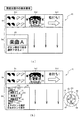
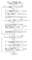
図7(a),(b)は、大当たり待機状態において実行される待機状態演出中の表示態様を示した図である。図7(a)に示した通り、大当たり待機状態になると、第3図柄表示装置81の表示画面における正面視上側に、「大当たり確定!」という文字が表示された表示領域HR1が形成される。この表示領域HR1の表示内容により、遊技者に対して大当たりが確定した(大当たりの権利を得た)ことを容易に認識させることができる。また、表示領域HR1の下方には、大当たり待機状態となる前に実行されていた変動表示演出において最終的に停止表示(確定表示)された第3図柄の組み合わせ(最終停止図柄)が表示される。大当たり待機状態の間も最終停止図柄を表示させておくことにより、今回の大当たりが確変大当たりであるか、通常大当たりであるかを遊技者が任意のタイミングで容易に確認することができる。
7 (a) and 7 (b) are views showing a display mode during the standby state effect executed in the jackpot standby state. As shown in FIG. 7A, in the jackpot standby state, a display area HR1 in which the characters "Big hit confirmed!" Is displayed is formed on the upper side of the front view on the display screen of the third
最終停止図柄に対して正面視右側には、縦長で、縦方向に6つの小領域に分割されているチャンスメーターCMが表示されている。このチャンスメーターCMを構成する各領域は、消灯した見た目となる態様と、発光した見た目となる態様とに可変可能に構成されており、発光した見た目となっている小領域の個数によって、作動入賞口660に遊技球を入球させた際の有利度合いを示唆する構成としている。より具体的には、小領域の個数は、通過検出センサ228a〜228fのうち、出力がH(ハイ)となっているセンサの個数に応じて、下側の小領域から順番(優先的)に発光した見た目(点灯態様)に設定される構成となっている。つまり、チャンスメーターCMのうち、発光した見た目(点灯態様)となっている小領域の個数分の遊技球が、少なくとも開閉扉65f1の上面を通過中である(開閉扉65f1が開放された場合に右特定入賞口65aへと入賞させることができる)ことが示唆される。以降、説明の簡略化のため、チャンスメーターCMのうち、発光した見た目の小領域のことを「ゲージ」と称し、発光した見た目の小領域の個数のことを「ゲージ数」と称し、小領域が発光した見た目に可変することを、「ゲージが貯まる」と称することにする。
On the right side of the front view with respect to the final stop symbol, a chance meter CM that is vertically long and is divided into six small areas in the vertical direction is displayed. Each region constituting the chance meter CM is variably configured to have a mode in which the light is turned off and a mode in which the light is emitted, and an operation prize is obtained depending on the number of small regions having the appearance of emitting light. The configuration suggests the degree of advantage when a game ball is inserted into the
最終停止図柄の下方には、「「GO!」を狙うとメーターチャージ!!」との文字と、「タイミングを合わせて右上を狙え!!」との文字と、作動入賞口660を狙うように示唆する画像とが表示された表示領域HR2が形成される。この表示領域HR2の表示内容により、遊技者に対して「GO!」の文字が付された普通入球口(スルーゲート)67(図2参照)を狙うことにより、表示画面における正面視右側に表示されたチャンスメーターCMのゲージ数を増加させることができるということを容易に理解させることができる。なお、上述した通り、このチャンスメーターCMは、開閉扉65f1の上面に配設されている通過検出センサ228a〜228fの検出内容に連動してゲージ数が可変される。普通入球口(スルーゲート)67に入球する程度の発射強度(発射速度)で遊技球を発射することにより、その下流に配設されている可変入賞装置65に対しても遊技球を到達させることができる。よって、普通入球口(スルーゲート)67が配置されている方向に向けて連続して遊技球を発射することで、可変入賞装置65の開閉扉65f1の上面にも遊技球が連続して到達する。この状態で、表示領域HR2の表示内容に従って作動入賞口660を狙って(即ち、95%〜100%の発射強度で)遊技球を発射することにより、大当たりが開始されて開閉扉65f1が開放される。これにより、開閉扉65f1を流下中の遊技球をほぼ右特定入賞口65aに入賞(入球)させることができる。なお、上述した通り、作動入賞口660に対して正面視左方には、一定の回転速度で回転動作を行う回動部材670aが設けられている。この回動部材670aは、その回転位置に応じて、作動入賞口660へと遊技球が入球することを妨げ得るため、遊技者に対して、チャンスメーターCMのゲージ数だけでなく、回動部材670aの回転位置も加味した発射タイミングで遊技球を発射させることができる。よって、大当たり待機状態における遊技者の遊技に対する興趣をより向上させることができる。
Below the final stop symbol, "GO!" Is aimed at and the meter is charged! !! A display area HR2 is formed in which the characters "", the characters "Aim at the upper right at the same timing !!", and an image suggesting to aim at the
図7(b)は、チャンスメーターCMのゲージが3つ分貯まっている状態を示した図である。図7(b)に示した通り、通過検出センサ228c〜228eの3つのセンサの上側を遊技球が通過中となっている場合に、これら3つのセンサの出力がH(ハイ)となる。音声ランプ制御装置113は、H出力となっているセンサの個数を検出して、チャンスメーターCMの態様に反映させる。図7(b)の例では、3つのセンサ(通過検出センサ228c〜228e)の出力がHとなっているので、チャンスメーターCMのゲージが3つ貯まった状態の態様で表示される。このように、開閉扉65f1の上面を通過中の遊技球の個数を通過検出センサ228a〜228fによって検出し、検出結果に応じて、通過中の遊技球の個数の目安をチャンスメーターCMのゲージ数で表示させる構成とすることにより、遊技者に対して作動入賞口660を狙うべきタイミングをより分かり易くすることができる。よって、パチンコ機10での遊技を行った経験が浅い遊技者に対しても、作動入賞口660を狙うタイミングを直感的に理解させ易くすることができる。これにより、初めて遊技を行う遊技者に対しても、気軽に遊技を行わせることができるので、パチンコ機10の稼働率を向上させることができる。
FIG. 7B is a diagram showing a state in which three gauges of the chance meter CM are stored. As shown in FIG. 7B, when the game ball is passing above the three sensors of the
なお、本第1実施形態では、大当たり待機状態において、開閉扉65f1の上面を通過中の遊技球の個数の目安をチャンスメーターCMのゲージ数によって示唆することで、作動入賞口660へと遊技球を入球させた場合の有利度合いを示唆する構成としていたが、これに限られるものではない。例えば、チャンスメーターCMのゲージ数によって大当たりの有利度合いを示唆する構成としてもよい。具体的には例えば、チャンスメーターCMのゲージ数によって、大当たり種別を示唆することにより、作動入賞口660に遊技球を入球させた場合の有利度合いを遊技者に示唆する構成としてもよい。また、例えば、大当たりが確定した時点では大当たりのラウンド数が不定となるように構成し、作動入賞口660を通過させたタイミングで大当たりのラウンド数を抽選する構成としてもよい。そして、ゲージ数によって、作動入賞口660に遊技球を入球させた場合に実行される抽選で決定されるラウンド数を示唆することで、作動入賞口660に遊技球を入球させた場合の有利度合いを遊技者に示唆する構成としてもよい。
In the first embodiment, the number of game balls passing through the upper surface of the opening / closing door 65f1 in the jackpot standby state is suggested by the number of gauges of the chance meter CM, so that the game balls reach the
図2に戻って説明を続ける。遊技盤13の右下側の隅部には、証紙や識別ラベル等を貼着するための貼着スペースK1が設けられている。この、貼着スペースK1に貼られた証紙等は、前面枠14の小窓35(図1参照)を通じて視認することができる。
The explanation will be continued by returning to FIG. A sticking space K1 for sticking a certificate stamp, an identification label, or the like is provided in the lower right corner of the
更に、遊技盤13には、アウト口66が設けられている。いずれの入賞口にも入賞しなかった遊技球はアウト口66を通って図示しない球排出路へと案内される。遊技盤13には、遊技球の落下方向を適宜分散、調整等するために多数の釘が植設されているとともに、風車等の各種部材(役物)が配設されている。
Further, the
図3に示すように、パチンコ機10の背面側には、制御基板ユニット90、91と、裏パックユニット94とが主に備えられている。制御基板ユニット90は、主基板(主制御装置110)と音声ランプ制御基板(音声ランプ制御装置113)と表示制御基板(表示制御装置114)とが搭載されてユニット化されている。制御基板ユニット91は、払出制御基板(払出制御装置111)と発射制御基板(発射制御装置112)と電源基板(電源装置115)とカードユニット接続基板116とが搭載されてユニット化されている。
As shown in FIG. 3, the
裏パックユニット94は、保護カバー部を形成する裏パック92と払出ユニット93とがユニット化されている。また、各制御基板には、各制御を司る1チップマイコンとしてのMPU、各種機器との連絡をとるポート、各種抽選の際に用いられる乱数発生器、時間計数や同期を図る場合などに使用されるクロックパルス発生回路等が、必要に応じて搭載されている。
In the
なお、主制御装置110、音声ランプ制御装置113及び表示制御装置114、払出制御装置111及び発射制御装置112、電源装置115、カードユニット接続基板116は、それぞれ基板ボックス100〜104に収納されている。基板ボックス100〜104は、ボックスベースと該ボックスベースの開口部を覆うボックスカバーとを備えており、そのボックスベースとボックスカバーとが互いに連結されて、各制御装置や各基板が収納される。
The
また、基板ボックス100(主制御装置110)及び基板ボックス102(払出制御装置111及び発射制御装置112)は、ボックスベースとボックスカバーとを封印ユニット(図示せず)によって開封不能に連結(かしめ構造による連結)している。また、ボックスベースとボックスカバーとの連結部には、ボックスベースとボックスカバーとに亘って封印シール(図示せず)が貼着されている。この封印シールは、脆性な素材で構成されており、基板ボックス100,102を開封するために封印シールを剥がそうとしたり、基板ボックス100,102を無理に開封しようとすると、ボックスベース側とボックスカバー側とに切断される。よって、封印ユニット又は封印シールを確認することで、基板ボックス100,102が開封されたかどうかを知ることができる。
Further, in the board box 100 (main control device 110) and the board box 102 (
払出ユニット93は、裏パックユニット94の最上部に位置して上方に開口したタンク130と、タンク130の下方に連結され下流側に向けて緩やかに傾斜するタンクレール131と、タンクレール131の下流側に縦向きに連結されるケースレール132と、ケースレール132の最下流部に設けられ、払出モータ216(図8参照)の所定の電気的構成により遊技球の払出を行う払出装置133とを備えている。タンク130には、遊技ホールの島設備から供給される遊技球が逐次補給され、払出装置133により必要個数の遊技球の払い出しが適宜行われる。タンクレール131には、当該タンクレール131に振動を付加するためのバイブレータ134が取り付けられている。
The
また、払出制御装置111には状態復帰スイッチ120が設けられ、発射制御装置112には可変抵抗器の操作つまみ121が設けられ、電源装置115にはRAM消去スイッチ122(図3参照)が設けられている。状態復帰スイッチ120は、例えば、払出モータ216(図8参照)部の球詰まり等、払出エラーの発生時に球詰まりを解消(正常状態への復帰)するために操作される。操作つまみ121は、発射ソレノイドの発射力を調整するために操作される。RAM消去スイッチ122(図3参照)は、パチンコ機10を初期状態に戻したい場合に電源投入時に操作される。
Further, the
<第1実施形態における電気的構成について>
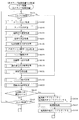
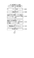
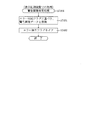
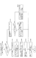
次に、図8を参照して、本パチンコ機10の電気的構成について説明する。図8は、パチンコ機10の電気的構成を示すブロック図である。
<About the electrical configuration in the first embodiment>
Next, the electrical configuration of the
主制御装置110には、演算装置である1チップマイコンとしてのMPU201が搭載されている。MPU201には、該MPU201により実行される各種の制御プログラムや固定値データを記憶したROM202と、そのROM202内に記憶される制御プログラムの実行に際して各種のデータ等を一時的に記憶するためのメモリであるRAM203と、そのほか、割込回路やタイマ回路、データ送受信回路などの各種回路が内蔵されている。なお、払出制御装置111や音声ランプ制御装置113などのサブ制御装置に対して動作を指示するために、主制御装置110から該サブ制御装置へ各種のコマンドがデータ送受信回路によって送信されるが、かかるコマンドは、主制御装置110からサブ制御装置へ一方向にのみ送信される。
The
主制御装置110では、大当たり抽選や第1図柄表示装置37および第3図柄表示装置81における表示の設定、第2図柄表示装置83における表示結果の抽選といったパチンコ機10の主要な処理を実行する。RAM203には、これらの処理を制御するための各種カウンタを格納するカウンタ用バッファ(図12参照)が設けられている。
The
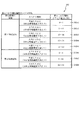
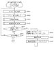
ここで、図12を参照して、主制御装置110のRAM203内に設けられるカウンタ等について説明する。これらのカウンタ等は、大当たり抽選や第1図柄表示装置37および第3図柄表示装置81の表示の設定、第2図柄表示装置83の表示結果の抽選などを行うために、主制御装置110のMPU201で使用される。
Here, with reference to FIG. 12, a counter and the like provided in the
大当たり抽選や第1図柄表示装置37および第3図柄表示装置81の表示の設定には、大当たりの抽選に使用する第1当たり乱数カウンタC1と、大当たり図柄の選択に使用する第1当たり種別カウンタC2と、停止種別を選択するために使用する停止種別カウンタC3と、変動パターンの選択に使用する変動種別カウンタCS1と、第1当たり乱数カウンタC1の初期値設定に使用する第1初期値乱数カウンタCINI1とが用いられる。また、普通図柄(第2図柄表示装置83)の抽選には、第2当たり乱数カウンタC4が用いられ、第2当たり乱数カウンタC4の初期値設定には第2初期値乱数カウンタCINI2が用いられる。これら各カウンタは、更新の都度前回値に1が加算され、最大値に達した後0に戻るループカウンタとなっている。
The jackpot lottery and the display settings of the first
各カウンタは、例えば、タイマ割込処理(図21参照)の実行間隔である2ミリ秒間隔で更新され、また、一部のカウンタは、メイン処理(図30参照)の中で不定期に更新されて、その更新値がRAM203の所定領域に設定されたカウンタ用バッファに適宜格納される。RAM203には、4つの保留エリア(保留第1〜第4エリア)からなる第1特別図柄保留球格納エリア203aが設けられており、これらの各エリアには、第1入球口64への入球タイミングに合わせて、第1当たり乱数カウンタC1、第1当たり種別カウンタC2及び停止種別選択カウンタC3の各値がそれぞれ格納される。また、RAM203には、4つの保留エリア(保留第1〜第4エリア)からなる第2特別図柄保留球格納エリア203bが設けられており、これらの各エリアには、第2入球口640への入球タイミングに合わせて、第1当たり乱数カウンタC1、第1当たり種別カウンタC2及び停止種別選択カウンタC3の各値がそれぞれ格納される。また、RAM203には、実行エリア203cが設けられており、抽選を実行する対象となる第1当たり乱数カウンタC1、第1当たり種別カウンタC2及び停止種別選択カウンタC3の各値が格納される。更に、RAM203には、1つの実行エリアと4つの保留エリア(保留第1〜第4エリア)とからなる普通図柄保留球格納エリア203dが設けられており、これらの各エリアには、遊技球が普通入球口(スルーゲート)67を通過したタイミングに合わせて、第2当たり乱数カウンタC4の値が格納される。
Each counter is updated, for example, at intervals of 2 milliseconds, which is the execution interval of the timer interrupt process (see FIG. 21), and some counters are updated irregularly in the main process (see FIG. 30). Then, the updated value is appropriately stored in the counter buffer set in the predetermined area of the
各カウンタについて詳しく説明する。第1当たり乱数カウンタC1は、所定の範囲(例えば、0〜399)内で順に1ずつ加算され、最大値(例えば、0〜399の値を取り得るカウンタの場合は399)に達した後0に戻る構成となっている。特に、第1当たり乱数カウンタC1が1周した場合、その時点の第1初期値乱数カウンタCINI1の値が当該第1当たり乱数カウンタC1の初期値として読み込まれる。 Each counter will be described in detail. The first random number counter C1 is incremented by 1 in order within a predetermined range (for example, 0 to 399), and after reaching the maximum value (for example, 399 in the case of a counter capable of taking a value of 0 to 399), it is 0. It is configured to return to. In particular, when the first random number counter C1 makes one round, the value of the first initial value random number counter CINI1 at that time is read as the initial value of the first random number counter C1.
また、第1初期値乱数カウンタCINI1は、第1当たり乱数カウンタC1と同一範囲で更新されるループカウンタとして構成される。即ち、例えば、第1当たり乱数カウンタC1が0〜399の値を取り得るループカウンタである場合には、第1初期値乱数カウンタCINI1もまた、0〜399の範囲のループカウンタである。この第1初期値乱数カウンタCINI1は、タイマ割込処理(図21参照)の実行毎に1回更新されると共に、メイン処理(図30参照)の残余時間内で繰り返し更新される。 Further, the first initial value random number counter CINI1 is configured as a loop counter updated in the same range as the first random number counter C1. That is, for example, when the first random number counter C1 is a loop counter capable of taking a value of 0 to 399, the first initial value random number counter CINI1 is also a loop counter in the range of 0 to 399. The first initial value random number counter CINI1 is updated once for each execution of the timer interrupt process (see FIG. 21), and is repeatedly updated within the remaining time of the main process (see FIG. 30).
第1当たり乱数カウンタC1の値は、例えば定期的に(本実施形態ではタイマ割込処理毎に1回)更新され、遊技球が第1入球口64に入球した場合には、その値がRAM203の第1特別図柄保留球格納エリア203aに格納される。一方、遊技球が第2入球口640に入球した場合には、その値が第2特別図柄保留球格納エリア203bに格納される。
The value of the first random number counter C1 is updated periodically (once for each timer interrupt process in this embodiment), and when the game ball enters the
上述した通り、特別図柄の大当たりとなる乱数の値は、主制御装置110のROM202に格納される第1当たり乱数テーブル202a(図9(b)参照)によって設定されており、第1当たり乱数カウンタC1の値が、第1当たり乱数テーブルによって設定された大当たりとなる乱数の値と一致する場合に、特別図柄の大当たりと判定する。また、この第1当たり乱数テーブル202aは、特別図柄の低確率時(特別図柄の低確率状態である期間)用と、その低確率時より特別図柄の大当たりとなる確率の高い高確率時(特別図柄の確変状態である期間)用との2種類に分けられ、それぞれに含まれる大当たりとなる乱数の個数が異なって設定されている(図9(b)参照)。このように、大当たりとなる乱数の個数を異ならせることにより、特別図柄の低確率時と特別図柄の高確率時とで、大当たりとなる確率が変更される。
As described above, the value of the random number that becomes the jackpot of the special symbol is set by the first random number table 202a (see FIG. 9B) stored in the
第1当たり種別カウンタC2は、特別図柄の大当たりとなった場合に、第1図柄表示装置37の表示態様を決定するものであり、所定の範囲(例えば、0〜99)内で順に1ずつ加算され、最大値(例えば、0〜99の値を取り得るカウンタの場合は99)に達した後0に戻る構成となっている。第1当たり種別カウンタC2の値は、例えば、定期的に(本実施形態ではタイマ割込処理毎に1回)更新され、遊技球が第1入球口64に入球した場合には、その値がRAM203の第1特別図柄保留球格納エリア203a(特別図柄の抽選が実行中でない場合は実行エリア203c)に格納される。一方、遊技球が第2入球口640へと入球した場合には、その値がRAM203の第2特別図柄保留球格納エリア203b(特別図柄の抽選が実行中でない場合は実行エリア203c)に格納される。
The first hit type counter C2 determines the display mode of the first
ここで、実行エリア203cに格納された第1当たり乱数カウンタC1の値が、特別図柄の大当たりとなる乱数でなければ、即ち、特別図柄の外れとなる乱数であれば、第1図柄表示装置37に表示される停止図柄に対応した表示態様は、特別図柄の外れ時のものとなる。
Here, if the value of the first hit random number counter C1 stored in the
一方で、実行エリア203cに格納された第1当たり乱数カウンタC1の値が、特別図柄の大当たりとなる乱数であれば、第1図柄表示装置37に表示される停止図柄に対応した表示態様は、特別図柄の大当たり時のものとなる。この場合、その大当たり時の具体的な表示態様は、同じ第1特別図柄保留球格納エリア203a、または第2特別図柄保留球格納エリア203bに格納されている第1当たり種別カウンタC2の値が示す表示態様となる。
On the other hand, if the value of the first hit random number counter C1 stored in the
本実施形態のパチンコ機10における第1当たり乱数カウンタC1は、0〜399の範囲の2バイトのループカウンタとして構成されている。この第1当たり乱数カウンタC1において、特別図柄の低確率時に、特別図柄の大当たりとなる乱数値は2個あり、その乱数値である「0,1」は、低確率時用の第1当たり乱数テーブルに格納されている(図9(b)の202a1参照)。このように特別図柄の低確率時には、乱数値の総数が400ある中で、大当たりとなる乱数値の総数が2なので、特別図柄の大当たりとなる確率は、「1/200」となる。なお、大当たりとなる乱数値(カウンタ値)は、第1特別図柄の抽選と、第2特別図柄の抽選とで共通である。
The first random number counter C1 in the
一方で、特別図柄の高確率時に、特別図柄の大当たりとなる乱数値は20個あり、その値である「0〜19」は、高確率時用の第1当たり乱数テーブルに格納されている(図9(b)の202a2参照)。このように特別図柄の高確率時には、乱数値の総数が400ある中で、大当たりとなる乱数値の総数が20なので、特別図柄の大当たりとなる確率は、「1/20」となる。 On the other hand, when the special symbol has a high probability, there are 20 random number values that are big hits of the special symbol, and the values "0 to 19" are stored in the first random number table for the high probability ( See 202a2 in FIG. 9B). As described above, when the probability of the special symbol is high, the total number of random numbers that will be the jackpot is 20 while the total number of random numbers is 400, so the probability of the special symbol being the jackpot is "1/20".
また、本実施形態のパチンコ機10における第1当たり種別カウンタC2の値は、0〜99の範囲のループカウンタとして構成されている。そして、図10(a)に示すように、第1特別図柄の抽選で大当たりとなり、第1当たり種別カウンタC2の値が「0〜4」であった場合の大当たり種別は、「大当たりA」(8ラウンド確変大当たり)となる。また、値が「5〜64」であった場合の大当たり種別は、「大当たりB」(5ラウンド確変大当たり)となり、値が「65〜99」であった場合の大当たり種別は、「大当たりC」(5ラウンド通常大当たり)となる。
Further, the value of the first type counter C2 in the
一方、第2特別図柄の抽選で大当たりとなり、第1当たり種別カウンタC2の値が「0〜4」であった場合の大当たり種別は、「大当たりD」(16ラウンド確変大当たり)となる。また、値が「5〜64」であった場合の大当たり種別は、「大当たりE」(10ラウンド確変大当たり)となり、値が「65〜99」であった場合の大当たり種別は、「大当たりF」(10ラウンド通常大当たり)となる。 On the other hand, when the lottery of the second special symbol is a big hit and the value of the first hit type counter C2 is "0-4", the big hit type is "big hit D" (16 round probability variation big hit). In addition, the jackpot type when the value is "5 to 64" is "big hit E" (10 round probability variation jackpot), and the jackpot type when the value is "65 to 99" is "big hit F". (10 rounds usually a big hit).
このように、本実施形態のパチンコ機10は、特別図柄の種類、および第1当たり種別カウンタC2が示す乱数の値によって、6種類の当たり種別(大当たりA〜F)が決定されるように構成されている。
As described above, the
停止種別選択カウンタC3は、例えば0〜99の範囲内で順に1ずつ加算され、最大値(つまり99)に達した後0に戻る構成となっている。本実施形態では、停止種別選択カウンタC3によって、第3図柄表示装置81で表示される外れ時の停止種別が選択され、リーチが発生した後、最終停止図柄がリーチ図柄の前後に1つだけずれて停止する「前後外れリーチ」(例えば98,99)と、同じくリーチ発生した後、最終停止図柄がリーチ図柄の前後以外で停止する「前後外れ以外リーチ」(例えば90〜97の範囲)と、リーチ発生しない「完全外れ」(例えば0〜89の範囲)との3つの停止(演出)パターンが選択される。停止種別選択カウンタC3の値は、例えば定期的に(本実施形態ではタイマ割込処理毎に1回)更新され、遊技球が第1入球口64に入球した場合は、その値がRAM203の第1特別図柄保留球格納エリア203a(特別図柄の抽選が実行中でない場合は実行エリア203c)に格納される。また、遊技球が第2入球口640に入球した場合は、その値がRAM203の第2特別図柄保留球格納エリア203b(特別図柄の抽選が実行中でない場合は実行エリア203c)に格納される。
The stop type selection counter C3 is configured to be incremented by 1 in order within the range of 0 to 99, and return to 0 after reaching the maximum value (that is, 99). In the present embodiment, the stop type selection counter C3 selects the stop type at the time of disconnection displayed by the third
なお、停止種別選択カウンタC3の値(乱数値)から、特別図柄の停止種別を決定するための乱数値は、停止種別選択テーブル(図示せず)により設定されており、このテーブルは、主制御装置110のROM202内に設けられている。また、本実施形態ではこのテーブルを、特別図柄の高確率時用と、特別図柄の低確率時用とに分けており、テーブルに応じて、外れの停止種別ごとに設定される乱数値の範囲を変えている。これは、パチンコ機10が特別図柄の高確率状態であるか、特別図柄の低確率状態であるか等に応じて、停止種別の選択比率を変更するためである。
From the value (random number value) of the stop type selection counter C3, the random number value for determining the stop type of the special symbol is set by the stop type selection table (not shown), and this table is the main control. It is provided in the
例えば、高確率状態では、大当たりが発生し易いため必要以上にリーチ演出が選択されないように、「完全外れ」の停止種別に対応した乱数値の範囲が0〜89と広い高確率時用のテーブルが選択され、「完全外れ」が選択され易くなる。このテーブルは、「前後外れリーチ」が98,99と狭くなると共に「前後外れ以外リーチ」も90〜97と狭くなり、「前後外れリーチ」や「前後外れ以外リーチ」が選択され難くなる。また、低確率状態であれば、第1入球口64への遊技球の入球時間を確保するために「完全外れ」の停止種別に対応した乱数値の範囲が0〜79と狭い低確率時用のテーブルが選択され、「完全外れ」が選択され難くなる。
For example, in a high-probability state, a table for high-probability times has a wide range of random numbers from 0 to 89 corresponding to the stop type of "completely off" so that the reach effect is not selected more than necessary because a big hit is likely to occur. Is selected, and "completely off" is easily selected. In this table, the "reach outside the front and rear" is narrowed to 98,99, and the "reach other than the front and rear" is also narrowed to 90 to 97, making it difficult to select "reach outside the front and rear" or "reach other than the front and rear". Further, in the low probability state, the range of the random number value corresponding to the stop type of "completely off" is narrow as 0 to 79 in order to secure the entry time of the game ball into the
この停止種別選択テーブルは、「前後外れ以外リーチ」の停止種別に対応した乱数値の範囲が80〜97と広くなり、「前後外れ以外リーチ」が選択され易くなっている。よって、低確率状態では、演出時間の長いリーチ表示を多く行うことできるので、第1入球口64への遊技球の入球時間を確保でき、第3図柄表示装置81による変動表示が継続して行われ易くなる。なお、後者のテーブルにおいても、「前後外れリーチ」の停止種別に対応した乱数値の範囲は98,99に設定される。
In this stop type selection table, the range of random value corresponding to the stop type of "reach other than front and rear deviation" is widened to 80 to 97, and "reach other than front and rear deviation" can be easily selected. Therefore, in the low probability state, it is possible to perform a lot of reach display with a long effect time, so that it is possible to secure the ball entry time of the game ball into the first
変動種別カウンタCS1は、例えば0〜198の範囲内で順に1ずつ加算され、最大値(つまり198)に達した後0に戻る構成となっている。変動種別カウンタCS1によって、いわゆるノーマルリーチ、スーパーリーチ等の大まかな表示態様が決定される。表示態様の決定は、具体的には、図柄変動の変動時間の決定である。変動種別カウンタCS1により決定された変動時間に基づいて、音声ランプ制御装置113や表示制御装置114により第3図柄表示装置81で表示される第3図柄のリーチ種別や細かな図柄変動態様が決定される。変動種別カウンタCS1の値は、後述するメイン処理(図30参照)が1回実行される毎に1回更新され、当該メイン処理内の残余時間内でも繰り返し更新される。なお、変動種別カウンタCS1の値(乱数値)から、図柄変動の変動時間を一つ決定する乱数値を格納した変動パターンテーブル202d(図11(a)参照)は、主制御装置110のROM202内に設けられている。
The variation type counter CS1 is configured to be incremented by 1 in order within the range of 0 to 198, and return to 0 after reaching the maximum value (that is, 198). The variable type counter CS1 determines a rough display mode such as so-called normal reach and super reach. Specifically, the determination of the display mode is the determination of the fluctuation time of the symbol variation. Based on the fluctuation time determined by the variation type counter CS1, the reach type and the detailed symbol variation mode of the third symbol displayed on the third
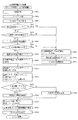
ここで、図11(a)〜(d)を参照して、変動パターンテーブル202dについて説明する。この変動パターンテーブル202dは、図11(a)に示すように、第1特別図柄の抽選に基づく変動パターンを選択するためのテーブルとして、大当たり用変動パターンテーブル202d1(図11(b)参照)と、外れ用(通常)変動パターンテーブル202d2(図11(c)参照)と、外れ用(確変)変動パターンテーブル202d3(図11(d)参照)とが少なくとも規定されている。 Here, the variation pattern table 202d will be described with reference to FIGS. 11A to 11D. As shown in FIG. 11A, the variation pattern table 202d is a table for selecting a variation pattern based on the lottery of the first special symbol, and is a table for selecting a variation pattern for jackpot 202d1 (see FIG. 11B). , The disengagement (normal) variation pattern table 202d2 (see FIG. 11C) and the disengagement (probability variation) variation pattern table 202d3 (see FIG. 11D) are at least specified.
まず、図11(b)を参照して、大当たり用変動パターンテーブル202d1について説明する。図11(b)は、この大当たり用変動パターンテーブル202d1の内容を模式的に示した模式図である。大当たり用変動パターンテーブル202d1は、特別図柄の抽選結果が大当たりである場合に、選択される変動パターンの種別(変動時間)が規定されたデータテーブルである。大当たりの変動パターンとしては、ノーマルリーチ各種(30秒)、スーパーリーチ各種(60秒)、スペシャルリーチ(90秒)がそれぞれ規定されている。大当たり用変動パターンテーブル202d1には、変動種別カウンタCS1の値毎に、各変動パターンが対応付けられている。 First, the jackpot variation pattern table 202d1 will be described with reference to FIG. 11B. FIG. 11B is a schematic diagram schematically showing the contents of the jackpot variation pattern table 202d1. The jackpot variation pattern table 202d1 is a data table in which the type (variation time) of the variation pattern selected when the lottery result of the special symbol is a jackpot is defined. Various normal reach (30 seconds), various super reach (60 seconds), and special reach (90 seconds) are defined as the fluctuation patterns of the jackpot. In the jackpot fluctuation pattern table 202d1, each fluctuation pattern is associated with each value of the fluctuation type counter CS1.
具体的には、変動種別カウンタCS1の値の判定値として「0〜50」の範囲にはノーマルリーチ各種(30秒)の変動パターンが対応付けられ、「51〜179」の範囲にはスーパーリーチ各種(60秒)の変動パターンが対応付けられ、「180〜198」の範囲にはスペシャルリーチ各種(90秒)の変動パターンが対応付けられている。主制御装置110のMPU201は、特別図柄の抽選結果が大当たりとなる場合の変動パターンを選択する場合に、取得している変動種別カウンタCS1の値に対応する判定値が設定されている変動パターンを大当たり用変動パターンテーブル202d1より選択する。
Specifically, as a judgment value of the value of the fluctuation type counter CS1, various fluctuation patterns of normal reach (30 seconds) are associated with the range of "0 to 50", and various super reach are associated with the range of "51 to 179". Fluctuation patterns of (60 seconds) are associated, and variation patterns of various special reach (90 seconds) are associated with the range of "180 to 198". The
図11(c)は、外れ用(通常)変動パターンテーブル202d2の内容を模式的に示した模式図である。外れ用(通常)変動パターンテーブル202d2は、特別図柄の低確率状態において、特別図柄の抽選結果が外れであった場合に選択される変動パターンの種別(変動時間)が規定されたデータテーブルである。特別図柄の抽選結果が外れである場合には、上述したように、図示しない停止種別選択テーブルより停止種別が完全外れ(非リーチ)であるか、リーチ外れ(リーチ共通)であるかが停止種別選択カウンタC3の値によって決定される。具体的には、例えば、特別図柄の低確率状態において停止種別選択カウンタC3の値が「0〜79」の範囲にあれば完全外れを設定し、「80〜99」の範囲にあれば外れリーチ(前後外れリーチ、前後外れ以外リーチ)を設定する。 FIG. 11C is a schematic diagram schematically showing the contents of the deviation pattern table 202d2 for detachment (normal). The deviation pattern table 202d2 is a data table in which the type (variation time) of the variation pattern selected when the lottery result of the special symbol is out of order in the low probability state of the special symbol is defined. .. If the lottery result of the special symbol is out of order, as described above, the stop type is completely out of reach (non-reach) or out of reach (common to reach) from the stop type selection table (not shown). It is determined by the value of the selection counter C3. Specifically, for example, in a low probability state of a special symbol, if the value of the stop type selection counter C3 is in the range of "0 to 79", a complete deviation is set, and if it is in the range of "80 to 99", the deviation reach is set. Set (reach out of front and back, reach other than out of front and back).
ここで、変動パターン種別が、完全外れである場合には、変動時間が比較的短い短外れ(7秒)と、変動時間が比較的長い長外れ(10秒)のいずれかが設定される。短外れ(7秒)に対しては、「0〜98」が、長外れ(10秒)に対しては、「99〜198」が変動種別カウンタCS1の判定値として設定されている。 Here, when the fluctuation pattern type is a complete deviation, either a short deviation (7 seconds) in which the fluctuation time is relatively short or a long deviation (10 seconds) in which the fluctuation time is relatively long is set. For a short deviation (7 seconds), "0 to 98" is set as a determination value, and for a long deviation (10 seconds), "99 to 198" is set as a determination value of the variation type counter CS1.
また、外れリーチに対しては、変動種別カウンタCS1の判定値が「0〜149」の範囲には外れのノーマルリーチ各種(30秒)が、「150〜197」の範囲には外れのスーパーリーチ各種(60秒)が、「198」には外れのスペシャルリーチ各種(90秒)がそれぞれ設定されている。 For the out-of-reach, various normal reach (30 seconds) out of the range of "0 to 149" for the judgment value of the fluctuation type counter CS1 and various super reach out of the range of "150 to 197". (60 seconds), but "198" is set with various special reach (90 seconds).
このように、主制御装置110のMPU201は、通常遊技状態時に特別図柄の抽選結果が外れである場合には、停止種別が決定され、外れ用(通常)変動パターンテーブル202d2より取得している変動種別カウンタCS1の値に基づいて、外れ用(通常)変動パターンテーブル202d2より変動パターンを選択する。
As described above, in the
図11(d)は、外れ用(確変)変動パターンテーブル202d3の内容を模式的に示した模式図である。この外れ用(確変)変動パターンテーブル202d3は、特別図柄の確変状態において、特別図柄の抽選が外れとなった場合に選択される変動パターンの種別(変動時間)が規定されたデータテーブルである。この外れ用(確変)変動パターンテーブル202d3では、設定されている変動種別カウンタCS1の値が、上述した外れ用(通常)変動パターンテーブル202d2とは異なっている。 FIG. 11D is a schematic diagram schematically showing the contents of the deviation pattern table 202d3 for deviation (probability variation). The deviation (probability variation) variation pattern table 202d3 is a data table in which the type (variation time) of the variation pattern selected when the lottery of the special symbol is missed in the probability variation state of the special symbol is defined. In the deviation (probability variation) fluctuation pattern table 202d3, the value of the variation type counter CS1 set is different from the deviation (normal) variation pattern table 202d2 described above.
なお、上述したように、遊技状態が確変遊技状態である場合には、図示しない停止種別選択テーブルにより停止種別選択カウンタC3の値が「0〜89」の範囲にあれば、完全外れが決定され、「90〜99」の範囲にあれば外れリーチ(前後外れリーチ、前後外れ以外リーチ)が決定される。 As described above, when the gaming state is the probabilistic gaming state, if the value of the stop type selection counter C3 is in the range of "0 to 89" by the stop type selection table (not shown), complete deviation is determined. , If it is in the range of "90 to 99", the out-of-reach (reach out of front and back, reach other than out of front and back) is determined.
このように、通常遊技状態よりも確変遊技状態である場合には、外れである場合にリーチとなる確率が低く設定されている。よって、確変時に外れの変動時間が長くなってしまい、大当たりとなるまでの期間が長くなってしまうことを抑制できる。よって、大当たりし易い確変遊技状態時に遊技が間延びしてしまい、遊技者が退屈に感じる不具合を抑制できる。 As described above, in the case of the probabilistic gaming state than in the normal gaming state, the probability of reaching is set lower when the game is out of the game. Therefore, it is possible to prevent the fluctuation time of the deviation from becoming long at the time of the probability change and the period until the jackpot becomes long. Therefore, it is possible to suppress a problem that the player feels bored because the game is delayed in the probabilistic game state where it is easy to hit the jackpot.
図12に戻って説明を続ける。第2当たり乱数カウンタC4は、例えば0〜239の範囲内で順に1ずつ加算され、最大値(つまり239)に達した後0に戻るループカウンタとして構成されている。また、第2当たり乱数カウンタC4が1周した場合、その時点の第2初期値乱数カウンタCINI2の値が当該第2当たり乱数カウンタC4の初期値として読み込まれる。第2当たり乱数カウンタC4の値は、本実施形態ではタイマ割込処理毎に、例えば定期的に更新され、遊技球がスルーゲート67を通過したことが検知された時に取得され、RAM203の普通図柄保留球格納エリア203dに格納される。
The explanation will be continued by returning to FIG. The second random number counter C4 is configured as a loop counter in which, for example, 1 is sequentially added in the range of 0 to 239, the maximum value (that is, 239) is reached, and then the counter returns to 0. Further, when the second hit random number counter C4 makes one round, the value of the second initial value random number counter CINI2 at that time is read as the initial value of the second hit random number counter C4. In the present embodiment, the value of the second random number counter C4 is updated periodically, for example, for each timer interrupt process, and is acquired when it is detected that the game ball has passed through the through
そして、普通図柄の当たりとなる乱数の値は、主制御装置のROM202に格納される第2当たり乱数テーブル202c(図10(b)参照)によって設定されており、第2当たり乱数カウンタC4の値が、第2当たり乱数テーブルによって設定された当たりとなる乱数の値と一致する場合に、普通図柄の当たりと判定する。また、この第2当たり乱数テーブルは、普通図柄の低確率時(普通図柄の通常状態である期間)用と、その低確率時より普通図柄の当たりとなる確率の高い高確率時(普通図柄の時短状態である期間)用との2種類に分けられ、それぞれに含まれる大当たりとなる乱数の個数が異なって設定されている(図10(b)参照)。このように、当たりとなる乱数の個数を異ならせることにより、普通図柄の低確率時と普通図柄の高確率時とで、当たりとなる確率が変更される。
The value of the random number that normally hits the symbol is set by the second hit random number table 202c (see FIG. 10B) stored in the
図10(b)に示すように、普通図柄の低確率時に、普通図柄の当たりとなる乱数値は24個あり、その値は「5〜28」である。このように、普通図柄の低確率時には、乱数値の総数が240ある中で、大当たりとなる乱数値の総数が24なので、特別図柄の大当たりとなる確率は、「1/10」となる。 As shown in FIG. 10B, when the probability of the normal symbol is low, there are 24 random numbers that can be hit by the normal symbol, and the values are "5 to 28". As described above, when the probability of a normal symbol is low, the total number of random numbers that become a jackpot is 24 while the total number of random numbers is 240, so the probability of a jackpot of a special symbol is "1/10".
パチンコ機10が普通図柄の低確率時である場合に、遊技球が普通入球口(スルーゲート)67を通過すると、第2当たり乱数カウンタC4の値が取得されると共に、第2図柄表示装置83において普通図柄の変動表示が30秒間実行される。そして、取得された第2当たり乱数カウンタC4の値が「5〜28」の範囲内であれば当選と判定されて、第2図柄表示装置83における変動表示が終了した後に、停止図柄(第2図柄)として「○」の図柄が点灯表示されると共に、第2入球口640に付随する電動役物640aが「0.2秒間×1回」だけ開放される。なお、本実施形態では、パチンコ機10が普通図柄の低確率時である場合に、普通図柄の当たりとなったら電動役物640aが「0.2秒間×1回」だけ開放されるが、開放時間や回数は任意に設定すれば良い。例えば、「0.5秒間×2回」開放しても良い。
When the
一方で、普通図柄の高確率時に、普通図柄の大当たりとなる乱数値は200個あり、その範囲は「5〜204」となっている。これらの乱数値は、高確率時用の第2当たり乱数テーブルに格納されている。このように特別図柄の低確率時には、乱数値の総数が240ある中で、大当たりとなる乱数値の総数が200なので、特別図柄の大当たりとなる確率は、「1/1.2」となる。 On the other hand, when there is a high probability of a normal symbol, there are 200 random values that are big hits of the normal symbol, and the range is "5 to 204". These random number values are stored in the second random number table for high probability. As described above, when the probability of the special symbol is low, the total number of random numbers that will be the jackpot is 200 while the total number of random numbers is 240, so the probability of the special symbol being the jackpot is "1 / 1.2".
パチンコ機10が普通図柄の高確率時である場合に、遊技球が普通入球口(スルーゲート)67を通過すると、第2当たり乱数カウンタC4の値が取得されると共に、第2図柄表示装置83において普通図柄の変動表示が3秒間実行される。そして、取得された第2当たり乱数カウンタC4の値が「5〜204」の範囲であれば普通図柄の当たりと判定される。この場合、第2図柄表示装置83における変動表示が終了した後に、停止図柄(第2図柄)として「○」の図柄が点灯表示されると共に、電動役物640aが「1秒間×2回」開放される。このように、普通図柄の高確率時には、普通図柄の低確率時と比較して、変動表示の時間が「30秒→3秒」と非常に短くなり、更に、電動役物640aの開放期間が「0.2秒×1回→1秒間×2回」と非常に長くなるので、第2入球口640へ遊技球が入球し易い状態となる。なお、本実施形態では、パチンコ機10が普通図柄の高確率時である場合に、普通図柄の当たりとなったら電動役物64aが「1秒間×2回」だけ開放されるが、開放時間や回数は任意に設定すれば良い。例えば、「3秒間×2回」開放しても良い。
When the
第2初期値乱数カウンタCINI2は、第2当たり乱数カウンタC4と同一範囲で更新されるループカウンタとして構成され(値=0〜239)、タイマ割込処理(図21参照)毎に1回更新されると共に、メイン処理(図30参照)の残余時間内で繰り返し更新される。 The second initial value random number counter CINI2 is configured as a loop counter that is updated in the same range as the second random number counter C4 (value = 0 to 239), and is updated once for each timer interrupt process (see FIG. 21). At the same time, it is repeatedly updated within the remaining time of the main process (see FIG. 30).
このように、RAM203には種々のカウンタ等が設けられており、主制御装置110では、このカウンタ等の値に応じて大当たり抽選や第1図柄表示装置37および第3図柄表示装置81における表示の設定、第2図柄表示装置83における表示結果の抽選といったパチンコ機10の主要な処理を実行することができる。
As described above, the
図8に戻り、説明を続ける。RAM203は、図12に図示したカウンタ用バッファのほか、MPU201の内部レジスタの内容やMPU201により実行される制御プログラムの戻り先番地などが記憶されるスタックエリアと、各種のフラグおよびカウンタ、I/O等の値が記憶される作業エリア(作業領域)とを有している。なお、RAM203は、パチンコ機10の電源の遮断後においても電源装置115からバックアップ電圧が供給されてデータを保持(バックアップ)できる構成となっており、RAM203に記憶されるデータは、すべてバックアップされる。
Returning to FIG. 8, the description will be continued. In addition to the counter buffer shown in FIG. 12, the
停電などの発生により電源が遮断されると、その電源遮断時(停電発生時を含む。以下同様)のスタックポインタや、各レジスタの値がRAM203に記憶される。一方、電源投入時(停電解消による電源投入を含む。以下同様)には、RAM203に記憶される情報に基づいて、パチンコ機10の状態が電源遮断前の状態に復帰される。RAM203への書き込みはメイン処理(図30参照)によって電源遮断時に実行され、RAM203に書き込まれた各値の復帰は電源投入時の立ち上げ処理(図29参照)において実行される。なお、MPU201のNMI端子(ノンマスカブル割込端子)には、停電等の発生による電源遮断時に、停電監視回路252からの停電信号SG1が入力されるように構成されており、その停電信号SG1がMPU201へ入力されると、停電時処理としてのNMI割込処理(図28参照)が即座に実行される。
When the power supply is cut off due to the occurrence of a power failure or the like, the stack pointer at the time of the power failure (including the time when the power failure occurs; the same applies hereinafter) and the value of each register are stored in the
次に、ROM202の具体的な内容について、図9(a)を参照して説明する。図9(a)は、本実施形態における主制御装置110内に設けられたROM202の構成を示すブロック図である。主制御装置110のROM202には、上記した固定値データの一部として、第1当たり乱数テーブル202a、第1当たり種別選択テーブル202b、第2当たり乱数テーブル202c、変動パターン選択テーブル202dが少なくとも記憶されている。
Next, the specific contents of the
第1当たり乱数テーブル202a(図9(b)参照)は、第1当たり乱数カウンタC1の値と、抽選結果との対応関係が規定されているデータテーブルである。具体的には、特別図柄の低確率状態において、大当たりと判定される判定値の範囲として「0,1」が規定され(図9(b)の202a1参照)、特別図柄の高確率状態(確変状態)において、大当たりと判定される判定値の範囲として「0〜19」が規定されている(図9(b)の202a2参照)。始動入賞に基づいて取得した第1当たり乱数カウンタC1の値が、この第1当たり乱数テーブル202a(図9(b)参照)に規定されている大当たりに対応する判定値のいずれかと一致した場合に、特別図柄の大当たりであると判別される。 The first random number table 202a (see FIG. 9B) is a data table in which the correspondence between the value of the first random number counter C1 and the lottery result is defined. Specifically, in the low probability state of the special symbol, "0,1" is defined as the range of the judgment values determined to be a big hit (see 202a1 in FIG. 9B), and the high probability state of the special symbol (probability change). In the state), “0 to 19” is defined as a range of determination values determined to be a big hit (see 202a2 in FIG. 9B). When the value of the first random number counter C1 acquired based on the starting prize matches any of the judgment values corresponding to the jackpot defined in the first random number table 202a (see FIG. 9B). , It is determined that it is a big hit of a special symbol.
第1当たり種別選択テーブル202b(図10(a)参照)は、大当たり種別を決定するための判定値が特別図柄の種別毎に記憶されているデータテーブルであり、第1当たり種別カウンタC2の判定値が、各大当たり種別に対応付けて規定されている。本実施形態のパチンコ機10では、特別図柄の大当たりと判定された場合に、始動入賞に基づいて取得した第1当たり種別カウンタC2の値と、第1当たり種別選択テーブル202bとが比較され、第1当たり種別カウンタC2の値に対応する大当たり種別が選択される。
The first hit type selection table 202b (see FIG. 10A) is a data table in which determination values for determining the jackpot type are stored for each type of special symbol, and the determination of the first hit type counter C2. The value is specified in association with each jackpot type. In the
図10(a)に示した通り、第1特別図柄に対して、第1当たり種別カウンタC2の値が「0〜4」の範囲には、「大当たりA」が対応付けられて規定されている(図10(a)の202b1参照)。この「大当たりA」は、ラウンド数が8ラウンドであり、大当たり終了後に、次に大当たりとなるまで継続する「特別図柄の確変状態」、および「普通図柄の時短状態」が付与される大当たりである。第1当たり種別カウンタC2の取り得る100個のカウンタ値のうち、「大当たりA」となるカウンタ値は5個なので、第1特別図柄の抽選で大当たりとなった場合に「大当たりA」が決定される割合は5%(5/100)である。この「大当たりA」は、第1特別図柄の大当たりの中で最もラウンド数が多く、且つ、大当たり終了後に有利な「特別図柄の確変状態」、および「普通図柄の時短状態」が付与されるので、第1特別図柄の大当たりの中で最も有利な大当たり種別である。 As shown in FIG. 10A, "big hit A" is associated with the first special symbol in the range where the value of the first hit type counter C2 is "0-4". (See 202b1 in FIG. 10A). This "big hit A" is a big hit in which the number of rounds is eight, and after the big hit is completed, a "probability change state of a special symbol" and a "time saving state of a normal symbol" that continue until the next big hit is given. .. Of the 100 counter values that the first hit type counter C2 can take, five counter values are "big hit A", so if a big hit is achieved in the first special symbol lottery, "big hit A" is determined. The ratio is 5% (5/100). This "big hit A" has the largest number of rounds among the big hits of the first special symbol, and is given an advantageous "probability change state of special symbol" and "time saving state of normal symbol" after the end of the jackpot. , The most advantageous jackpot type among the jackpots of the first special symbol.
第1特別図柄に対して、第1当たり種別カウンタC2の値が「5〜64」の範囲には、「大当たりB」が対応付けられて規定されている(図10(a)の202b2参照)。この「大当たりB」は、ラウンド数が5ラウンドであり、大当たり終了後に、次に大当たりとなるまで継続する「特別図柄の確変状態」、および「普通図柄の時短状態」が付与される大当たりである。第1当たり種別カウンタC2の取り得る100個のカウンタ値のうち、「大当たりB」となるカウンタ値は60個なので、第1特別図柄の抽選で大当たりとなった場合に「大当たりB」が決定される割合は60%(60/100)である。この「大当たりB」は、ラウンド数が少ないものの、「大当たりA」と同様に、大当たりの終了後に有利な「特別図柄の確変状態」、および「普通図柄の時短状態」が付与されるので、遊技者にとって比較的有利な大当たり種別である。 With respect to the first special symbol, the value of the first hit type counter C2 is defined in the range of "5 to 64" in association with "big hit B" (see 202b2 in FIG. 10A). .. This "big hit B" is a big hit in which the number of rounds is 5, and after the big hit is completed, a "probability change state of a special symbol" and a "time saving state of a normal symbol" that continue until the next big hit is given. .. Of the 100 counter values that the first hit type counter C2 can take, 60 counter values are "big hit B", so if a big hit is achieved in the lottery of the first special symbol, "big hit B" is determined. The ratio is 60% (60/100). Although the number of rounds is small, this "big hit B" is given an advantageous "probability change state of special symbol" and "time saving state of normal symbol" after the end of the jackpot, as in "big hit A". It is a jackpot type that is relatively advantageous for people.
第1特別図柄に対して、第1当たり種別カウンタC2の値が「65〜99」の範囲には、「大当たりC」が対応付けられて規定されている(図10(a)の202b3参照)。この「大当たりC」は、ラウンド数が5ラウンドであり、大当たり終了後に、特別図柄の抽選が100回終了するまでの間継続する「普通図柄の時短状態」が付与される大当たりである。第1当たり種別カウンタC2の取り得る100個のカウンタ値のうち、「大当たりC」となるカウンタ値は35個なので、第1特別図柄の抽選で大当たりとなった場合に「大当たりC」が決定される割合は35%(35/100)である。この「大当たりC」は、ラウンド数が少なく、且つ、大当たり終了後の遊技状態も、「大当たりA」や「大当たりB」に比較して不利となるため、遊技者にとって不利な大当たり種別となる。 With respect to the first special symbol, the value of the first hit type counter C2 is defined in the range of "65 to 99" in association with "big hit C" (see 202b3 in FIG. 10A). .. This "big hit C" is a big hit in which the number of rounds is 5, and after the big hit is completed, a "normal symbol time saving state" that continues until the lottery of the special symbol is completed 100 times is given. Of the 100 counter values that the first hit type counter C2 can take, 35 counter values are "big hit C", so if a big hit is achieved in the lottery of the first special symbol, "big hit C" is determined. The ratio is 35% (35/100). This "big hit C" has a small number of rounds, and the game state after the big hit is also disadvantageous as compared with "big hit A" and "big hit B", so that it is a disadvantageous jackpot type for the player.
また、図10(a)に示した通り、第2特別図柄に対して、第1当たり種別カウンタC2の値が「0〜4」の範囲には、「大当たりD」が対応付けられて規定されている(図10(a)の202b4参照)。この「大当たりD」は、ラウンド数が16ラウンドであり、大当たり終了後に、次に大当たりとなるまで継続する「特別図柄の確変状態」、および「普通図柄の時短状態」が付与される大当たりである。第1当たり種別カウンタC2の取り得る100個のカウンタ値のうち、「大当たりD」となるカウンタ値は5個なので、第2特別図柄の抽選で大当たりとなった場合に「大当たりD」が決定される割合は5%(5/100)である。この「大当たりD」は、ラウンド数が最も多い上に、大当たり終了後の遊技状態も有利となるため、遊技者にとって最も有利な大当たり種別となる。 Further, as shown in FIG. 10A, "big hit D" is associated with the second special symbol in the range where the value of the first hit type counter C2 is "0-4". (See 202b4 in FIG. 10A). This "big hit D" has 16 rounds, and is a big hit that is given a "probability change state of a special symbol" and a "time saving state of a normal symbol" that continue until the next big hit after the end of the big hit. .. Of the 100 counter values that the first hit type counter C2 can take, five counter values are "big hit D", so if a big hit is achieved in the second special symbol lottery, "big hit D" is determined. The ratio is 5% (5/100). This "big hit D" is the most advantageous jackpot type for the player because the number of rounds is the largest and the gaming state after the jackpot is finished is also advantageous.
第2特別図柄に対して、第1当たり種別カウンタC2の値が「5〜64」の範囲には、「大当たりE」が対応付けられて規定されている(図10(a)の202b5参照)。この「大当たりE」は、ラウンド数が10ラウンドであり、大当たり終了後に、次に大当たりとなるまで継続する「特別図柄の確変状態」、および「普通図柄の時短状態」が付与される大当たりである。第1当たり種別カウンタC2の取り得る100個のカウンタ値のうち、「大当たりE」となるカウンタ値は60個なので、第1特別図柄の抽選で大当たりとなった場合に「大当たりE」が決定される割合は60%(60/100)である。この「大当たりE」は、「大当たりD」に比較してラウンド数が少ないものの、大当たり終了後の遊技状態は「大当たりA」、「大当たりB」、および「大当たりD」と同様に有利な遊技状態が設定されるので、遊技者にとって有利な大当たり種別の一種である。 With respect to the second special symbol, the value of the first hit type counter C2 is defined in the range of "5 to 64" in association with "big hit E" (see 202b5 in FIG. 10A). .. This "big hit E" is a big hit in which the number of rounds is 10 and a "probability change state of a special symbol" and a "time saving state of a normal symbol" that continue until the next big hit is given after the big hit is completed. .. Of the 100 counter values that the first hit type counter C2 can take, 60 counter values are "big hit E", so if a big hit is achieved in the lottery of the first special symbol, "big hit E" is determined. The ratio is 60% (60/100). Although the number of rounds of this "big hit E" is smaller than that of "big hit D", the gaming state after the big hit is as advantageous as "big hit A", "big hit B", and "big hit D". Is set, so it is a kind of jackpot type that is advantageous for the player.
第2特別図柄に対して、第1当たり種別カウンタC2の値が「65〜99」の範囲には、「大当たりF」が対応付けられて規定されている(図10(a)の202b6参照)。この「大当たりF」は、ラウンド数が10ラウンドであり、大当たり終了後に、特別図柄の抽選が100回終了するまで継続する「普通図柄の時短状態」が付与される大当たりである。第1当たり種別カウンタC2の取り得る100個のカウンタ値のうち、「大当たりF」となるカウンタ値は35個なので、第1特別図柄の抽選で大当たりとなった場合に「大当たりF」が決定される割合は35%(35/100)である。この「大当たりF」は、ラウンド数は第1特別図柄の大当たり(「大当たりA」〜「大当たりC」)に比較して多いものの、大当たり終了後の遊技状態が不利となるため、遊技者にとって不利な大当たり種別である。 With respect to the second special symbol, the value of the first hit type counter C2 is defined in the range of "65 to 99" in association with "big hit F" (see 202b6 in FIG. 10A). .. This "big hit F" is a big hit in which the number of rounds is 10 rounds, and after the big hit is completed, a "normal symbol time saving state" that continues until the lottery of the special symbol is completed 100 times is given. Of the 100 counter values that the first hit type counter C2 can take, 35 counter values are "big hit F", so if a big hit is obtained in the lottery of the first special symbol, "big hit F" is determined. The ratio is 35% (35/100). Although the number of rounds of this "big hit F" is larger than that of the big hit of the first special symbol ("big hit A" to "big hit C"), the game state after the big hit is disadvantageous, which is disadvantageous for the player. It is a big hit type.
このように、第2特別図柄の抽選で大当たりになると、第1特別図柄の抽選よりもラウンド数が多い大当たり種別となるので、第1特別図柄の抽選よりも、第2特別図柄の抽選の方が遊技者にとって有利となる。なお、確変大当たりと通常大当たりとの比率は、第1特別図柄の抽選でも、第2特別図柄の抽選でも同一(確変大当たりが65%、通常大当たりが35%)となるように構成されている。 In this way, if a big hit is made in the lottery of the second special symbol, it will be a big hit type with more rounds than the lottery of the first special symbol, so the lottery of the second special symbol is better than the lottery of the first special symbol. Is advantageous for the player. The ratio of the probability variation jackpot to the normal jackpot is configured to be the same in both the lottery of the first special symbol and the lottery of the second special symbol (probability variation jackpot is 65%, normal jackpot is 35%).
第2当たり乱数テーブル202c(図10(b)参照)は、普通図柄の当たり判定値が規定(記憶)されているデータテーブルである。具体的には、普通図柄の通常状態において、普通図柄の当たりとなる判定値として、「5〜28」が規定されている(図10(b)の202c1参照)。また、普通図柄の高確率状態において、普通図柄の当たりとなる判定値として、「5〜204」が規定されている(図10(b)の202c2参照)。本実施形態のパチンコ機10では、普通入球口(スルーゲート)67を遊技球が通過することに基づいて取得される第2当たり乱数カウンタC4の値と、第2当たり乱数テーブル202cとを参照し、普通図柄の当たりであるか否かを判定している。
The second hit random number table 202c (see FIG. 10B) is a data table in which the hit determination value of the normal symbol is defined (stored). Specifically, in the normal state of the normal symbol, "5-28" is defined as a determination value for hitting the normal symbol (see 202c1 in FIG. 10 (b)). Further, in the high probability state of the normal symbol, "5-204" is defined as a determination value that is a hit of the normal symbol (see 202c2 in FIG. 10 (b)). In the
変動パターンテーブル202d(図11参照)は、変動パターンの表示態様を決定するための変動種別カウンタCS1の判定値が表示態様毎にそれぞれ規定されているデータテーブルである。なお、変動パターンテーブル202dの詳細については、変動種別カウンタCS1の説明において上述した通りであるので、ここではその詳細な説明について省略する。 The fluctuation pattern table 202d (see FIG. 11) is a data table in which the determination value of the fluctuation type counter CS1 for determining the display mode of the fluctuation pattern is defined for each display mode. Since the details of the fluctuation pattern table 202d are as described above in the description of the fluctuation type counter CS1, the detailed description thereof will be omitted here.
次に、RAM203の詳細について、図13を参照して説明する。図13は、主制御装置110のRAM203の構成を示すブロック図である。図13に示した通り、RAM203は、第1特別図柄保留球格納エリア203a、第2特別図柄保留球格納エリア203b、実行エリア203c、普通図柄保留球格納エリア203d、第1特別図柄保留球数カウンタ203e、第2特別図柄保留球数カウンタ203f、普通図柄保留球数カウンタ203g、確変フラグ203h、時短中カウンタ203i、入球待機フラグ203j、大当たり開始フラグ203k、大当たり中フラグ203m、その他メモリエリア203zを少なくとも有している。
Next, the details of the
第1特別図柄保留球格納エリア203aは、4つの保留エリア(保留第1エリア〜保留第4エリア)を有しており、これらの各エリアには、第1当たり乱数カウンタC1、第1当たり種別カウンタC2、及び停止種別選択カウンタC3の各値がそれぞれ格納される。
The first special symbol holding
より具体的には、遊技球が第1入球口64へ入賞(始動入賞)したタイミングで、各カウンタC1〜C3の各値が取得され、その取得されたデータが、4つの保留エリア(保留第1エリア〜保留第4エリア)の空いているエリアの中で、エリア番号(第1〜第4)の小さいエリアから順番に記憶される。つまり、エリア番号の小さいエリアほど、時間的に古い入賞に対応するデータが記憶され、保留第1エリアには、時間的に最も古い入賞に対応するデータが記憶される。なお、4つの保留エリアの全てにデータが記憶されている場合には、新たに何も記憶されない。 More specifically, each value of each counter C1 to C3 is acquired at the timing when the game ball wins a prize (starting prize) in the first ball opening 64, and the acquired data is stored in four holding areas (holding). Among the vacant areas (1st area to 4th reserved area), the areas with the smallest area numbers (1st to 4th) are stored in order. That is, the smaller the area number, the data corresponding to the time-old winning prize is stored, and the data corresponding to the time-oldest winning prize is stored in the reserved first area. If data is stored in all four holding areas, nothing is newly stored.
その後、主制御装置110において、特別図柄の抽選が行われる場合には、第1特別図柄保留球格納エリア203aの保留第1エリアに記憶されている各カウンタC1〜C3の値が、実行エリア203c(図12参照)へシフトされ(移動させられ)、その実行エリアに記憶された各カウンタC1〜C3の各値に基づいて、特別図柄の抽選などの判定が行われる。
After that, when the special symbol lottery is performed in the
なお、保留第1エリアから実行エリア203cへデータをシフトすると、保留第1エリアが空き状態となる。そこで、他の保留エリア(保留第2エリア〜保留第4エリア)に記憶されている入賞のデータを、エリア番号の1小さい保留エリア(保留第1エリア〜保留第3エリア)に詰めるシフト処理が行われる。本実施形態では、第1特別図柄保留球格納エリア203aにおいて、入賞のデータが記憶されている保留エリア(保留第2エリア〜保留第4エリア)についてのみデータのシフトが行われる。
When the data is shifted from the hold 1st area to the
第2特別図柄保留球格納エリア203bは、第1特別図柄保留球格納エリア203aと同様に、4つの保留エリアを有している。この第2特別図柄保留球格納エリア203bには、第2入球口640への始動入賞に基づいて取得される各カウンタ値が記憶される。カウンタ値の格納方法等については、第1特別図柄保留球格納エリア203aと同様であるため、その詳細な説明については省略する。
The second special symbol holding
実行エリア203cは、特別図柄の抽選を実行に用いるための各カウンタC1〜C3の値が格納される記憶領域である。この実行エリア203cに格納された各カウンタC1〜C3の値と、上述した第1当たり乱数テーブル202a、第1当たり種別選択テーブル202b等とが比較されて、特別図柄の抽選が実行される。
The
普通図柄保留球格納エリア203dは、1つの実行エリアと、4つの保留エリア(保留第1エリア〜保留第4エリア)とを有している。これらの各エリアには、第2当たり乱数カウンタC4が格納される。より具体的には、遊技球が普通入球口(スルーゲート)67を通過したタイミングで、カウンタC4の値が取得され、その取得されたデータが、4つの保留エリア(保留第1エリア〜保留第4エリア)の空いているエリアの中で、エリア番号(第1〜第4)の小さいエリアから順番に記憶される。つまり、第1特別図柄保留球格納エリア203aや、第2特別図柄保留球格納エリア203bと同様に、入賞した順序が保持されつつ、入賞に対応するデータが格納される。尚、4つの保留エリアの全てにデータが記憶されている場合には、新たに何も記憶されない。
The normal symbol holding
その後、主制御装置110において、普通図柄の当たりの抽選が行われる場合には、普通図柄保留球格納エリア203dの保留第1エリアに記憶されているカウンタC4の値が、実行エリアへシフトされ(移動させられ)、その実行エリアに記憶されたカウンタC4の値に基づいて、普通図柄の当たりの抽選などの判定が行われる。
After that, when the lottery for winning the normal symbol is performed in the
なお、保留第1エリアから実行エリアへデータをシフトすると、保留第1エリアが空き状態となるので、第1特別図柄保留球格納エリア203aや、第2特別図柄保留球格納エリア203bの場合と同様に、他の保留エリアに記憶されている入賞のデータを、エリア番号の1小さい保留エリアに詰めるシフト処理が行われる。また、データのシフトも、入賞のデータが記憶されている保留エリアについてのみ行われる。
When the data is shifted from the hold 1st area to the execution area, the hold 1st area becomes empty, so that the case is the same as in the case of the 1st special symbol hold
第1特別図柄保留球数カウンタ203eは、第1入球口64への入球(始動入賞)に基づいて第1図柄表示装置37で行われる特別図柄(第1図柄)の変動表示(第3図柄表示装置81で行われる変動表示)の保留球数(待機回数)を最大4回まで計数するカウンタである。この第1特別図柄保留球数カウンタ203eは、初期値がゼロに設定されており、第1入球口64へ遊技球が入球して変動表示の保留球数が増加する毎に、最大値4まで1ずつ加算される(図24のS404参照)。一方、第1特別図柄保留球数カウンタ203eは、新たに特別図柄の変動表示が実行される毎に、1減算される(図22のS210参照)。
The first special symbol reserved
この第1特別図柄保留球数カウンタ203eの値(第1特別図柄における変動表示の保留回数N1)は、保留球数コマンドによって音声ランプ制御装置113に通知される(図22のS211、図24のS405参照)。保留球数コマンドは、第1特別図柄保留球数カウンタ203eの値が変更される度に、主制御装置110から音声ランプ制御装置113に対して送信されるコマンドである。
The value of the first special symbol reserved
音声ランプ制御装置113は、第1特別図柄保留球数カウンタ203eの値が変更される度に、主制御装置110より送信される保留球数コマンドによって、主制御装置110に保留された変動表示の保留球数そのものの値を取得することができる。これにより、音声ランプ制御装置113の第1特別図柄保留球数カウンタ223bによって管理される変動表示の保留球数が、ノイズ等の影響によって、主制御装置110に保留された実際の変動表示の保留球数からずれてしまった場合であっても、次に受信する保留球数コマンドによって、そのずれを修正することができる。
The voice
なお、音声ランプ制御装置113は、保留球数コマンドに基づいて保留球数を管理し、保留球数が変化する度に表示制御装置114に対して、保留球数を通知するための表示用保留球数コマンドを送信する。表示制御装置114は、この表示用保留球数コマンドによって通知された保留球数を基に、第3図柄表示装置81に保留球数図柄を表示する。
The voice
第2特別図柄保留球数カウンタ203fは、第2入球口640への入球(始動入賞)に基づいて第1図柄表示装置37で行われる特別図柄(第1図柄)の変動表示(第3図柄表示装置81で行われる変動表示)の保留球数(待機回数)を最大4回まで計数するカウンタである。この第2特別図柄保留球数カウンタ203fは、初期値がゼロに設定されており、第2入球口640へ遊技球が入球して変動表示の保留球数が増加する毎に、最大値4まで1ずつ加算される(図24のS410参照)。一方、第2特別図柄保留球数カウンタ203fは、新たに特別図柄の変動表示が実行される毎に、1減算される(図22のS205参照)。この第2特別図柄保留球数カウンタ203fの値も、第1特別図柄保留球数カウンタ203eの値と同様に、保留球数コマンドによって音声ランプ制御装置113へと通知される。
The second special symbol reserved
普通図柄保留球数カウンタ203gは、普通入球口(スルーゲート)67における遊技球の通過に基づいて第2図柄表示装置83で行われる普通図柄(第2図柄)の変動表示の保留球数(待機回数)を最大4回まで計数するカウンタである。この普通図柄保留球数カウンタ203gは、初期値がゼロに設定されており、遊技球がスルーゲート67を通過して変動表示の保留球数が増加する毎に、最大値4まで1加算される(図27のS704参照)。一方、普通図柄保留球数カウンタ203gは、新たに普通図柄(第2図柄)の変動表示が実行される毎に、1減算される(図26のS605参照)。
The normal symbol reserved ball number counter 203 g is a reserved ball number (2) of the variable display of the normal symbol (second symbol) performed by the second
遊技球がスルーゲート67を通過した場合に、この普通図柄保留球数カウンタ203gの値(普通図柄における変動表示の保留回数M)が4未満であれば、第2当たり乱数カウンタC4の値が取得され、その取得されたデータが、普通図柄保留球格納エリア203dに記憶される(図27のS705)。一方、遊技球がスルーゲート67を通過した場合に、この普通図柄保留球数カウンタ203gの値が4であれば普通図柄保留球格納エリア203dには新たに何も記憶されない(図27のS703:No)。
When the game ball passes through the through
確変フラグ203hは、パチンコ機10が特別図柄の確変状態であるか否かを示すフラグであり、確変フラグ203hがオンであれば、パチンコ機10が特別図柄の確変状態であることを示し、確変フラグ203hがオフであれば、パチンコ機10が特別図柄の低確率状態であることを示す。また、上述した通り、特別図柄の確変状態の間は、普通図柄の時短状態となる。よって、確変フラグ203hがオンであれば、特別図柄の確変状態であると共に、普通図柄の時短状態であることも示している。
The
確変フラグ203hは、初期値がオフに設定されており、確変大当たり(「大当たりA」、「大当たりB」、「大当たりD」、「大当たりE」のいずれか)となった場合に、その大当たりの終了時にオンに設定される(図32のS1215参照)。また、確変フラグ203hは、大当たり遊技が開始される場合にオフにリセット設定される(図22のS219参照)。
The initial value of the
この確変フラグ203hは、特別図柄変動開始処理において遊技状態が確変状態であるか否かを判別するために参照される(図23のS302参照)。具体的には、特別図柄変動開始処理(図23、S213)が実行されると、特別図柄の抽選が行われる。特別図柄変動開始処理(図23、S213)では、確変フラグ203hが参照され、オンであれば、高確率時用の第1当たり乱数テーブル202a(図9(b)の202a2参照)に基づいて、特別図柄の抽選が行われる。一方、確変フラグ203hがオフであれば、低確率時用の第1当たり乱数テーブル202a(図9(b)の202a1参照)に基づいて、特別図柄の抽選が行われる。
The
また、確変フラグ203hは、普通図柄変動処理において遊技状態が時短状態であるか否かを判別するためにも参照される(図26のS608,S614,S620)。具体的には、普通図柄変動処理の中で確変フラグ203h、および後述する時短中カウンタ203iが参照され、確変フラグ203hがオンであるか、または時短中カウンタ203iの値が1以上であれば、普通図柄の時短状態中と判別されて、高確率時用の第2当たり乱数テーブル202c(図10(b)の202c2参照)に基づいて、普通図柄の抽選が行われる(図26のS609参照)。一方、確変フラグ203hがオフであり、且つ、時短中カウンタ203iの値が0であれば、普通図柄の通常状態中と判別されて、低確率時用の第2当たり乱数テーブル202c(図10(b)の202c1参照)に基づいて普通図柄の抽選が行われる(図26のS610参照)。また、普通図柄変動処理では、普通図柄の変動時間や、普通図柄の当たりとなった場合における電動役物640aの開放時間を決定する際にも確変フラグ203hが参照される(図26のS614,S620参照)。
The
時短中カウンタ203iは、パチンコ機10が普通図柄の時短状態であるか否かを示すカウンタであり、時短中カウンタ203iの値が1以上であれば、パチンコ機10が普通図柄の時短状態であることを示し、時短中カウンタ203iの値が0、且つ、確変フラグ203hがオフであれば、パチンコ機10が普通図柄の通常状態であることを示す。この時短中カウンタ203iは、初期値がゼロに設定されており、主制御装置110において特別図柄の抽選が行われ、通常大当たりとなる度に、その通常大当たりの終了時に値が100にセットされる(図32のS1214参照)。また、大当たり種別に関わらず、特別図柄の抽選により大当たりとなった場合は、その大当たりの開始を設定する中で値が0に設定される(図22のS219参照)。
The time saving
普通図柄の当たりの抽選が行われる場合には、時短中カウンタ203iの値、および確変フラグ203hの状態が参照され、時短中カウンタ203iの値が1以上であるか、確変フラグ203hがオンであれば、普通図柄の時短中と判別される。この場合、高確率時用の第2当たり乱数テーブルに基づいて、普通図柄の抽選が行われる(図26のS609参照)。一方、時短中カウンタ203iの値が0であり、且つ、確変フラグ203hがオフであれば、普通図柄の通常状態と判別されて、低確率時用の第2当たり乱数テーブルに基づいて、普通図柄の抽選が行われる(図26のS610参照)。
When a lottery for winning a normal symbol is performed, the value of the time saving /
入球待機フラグ203jは、作動入賞口660へと遊技球が入球するまで大当たりの開始が待機される大当たり待機状態であるか否かを示すフラグである。この入球待機フラグ203jがオンであれば、大当たり待機状態であることを意味し、オフであれば、大当たり待機状態ではないことを意味する。この入球待機フラグ203jは、特別図柄の抽選で大当たりとなり、当該大当たりに対応する変動パターンの変動時間が経過した際にオンに設定される(図22のS220参照)。また、入球待機フラグ203jは、大当たり待機状態中において、作動入賞口660へと遊技球が入球した場合にオフに設定される(図31のS1104参照)。この入球待機フラグ203jがオンの間は、作動入賞口660への入球が有効として扱われる(入球を検出した場合に大当たりが開始される)。
The ball
大当たり開始フラグ203kは、大当たりを開始させるか否かを示すフラグである。この大当たり開始フラグ203kがオンであれば、大当たりを開始させるタイミングである(作動入賞口660へと遊技球が入球して大当たり待機状態が終了した)ことを意味し、オフであれば、大当たりを開始させるタイミングではないことを意味する。この大当たり開始フラグ203kは、大当たり待機状態中に作動入賞口660へと遊技球が入球することでオンに設定される(図31のS1103参照)。また、大当たり開始フラグ203kは、大当たりの開始を設定した場合にオフに設定される(図32のS1203参照)。
The
大当たり中フラグ203mは、大当たり(特別遊技状態)中であるか否かを示すフラグである。この大当たり中フラグ203mがオンであれば、大当たり中であることを意味し、オフであれば大当たり中でないことを意味する。大当たり中フラグ203mは、特別図柄の抽選により大当たりとなり、大当たり(特別遊技状態)が開始されると共にオンに設定される(図32のS1203参照)。また、大当たり(特別遊技状態)の終了時にオフに設定される(図32のS1217参照)。特別図柄変動処理(図22参照)では、この大当たり中フラグ203mが参照されて、大当たり中であるか否かが判別される(図22のS201参照)。
The jackpot
その他メモリエリア203zは、主制御装置110のMPU201が使用するその他カウンタ値等を一時的に記憶しておくためのエリアである。
The
このように、主制御装置110のRAM203には、各種のカウンタやフラグが設けられている。
As described above, the
図8に戻って、説明を続ける。主制御装置110のMPU201には、アドレスバス及びデータバスで構成されるバスライン204を介して入出力ポート205が接続されている。入出力ポート205には、払出制御装置111、音声ランプ制御装置113、第1図柄表示装置37、第2図柄表示装置83、右特定入賞口65aおよび左特定入賞口650aを閉鎖または開放する開閉扉65f1を開閉駆動するための大開放口ソレノイドや電動役物を駆動するためのソレノイドなどからなるソレノイド209、回動部材670aを回転動作させるための回転体用モータ670cが接続され、MPU201は、入出力ポート205を介してこれらに対し各種コマンドや制御信号を送信する。
Returning to FIG. 8, the description will be continued. An input /
また、入出力ポート205には、図示しないスイッチ群やセンサ群などからなる各種スイッチ208や、電源装置115に設けられた後述のRAM消去スイッチ(図3、122)回路253が接続され、MPU201は各種スイッチ208から出力される信号や、RAM消去スイッチ(図3、122)回路253より出力されるRAM消去信号SG2に基づいて各種処理を実行する。
Further,
払出制御装置111は、払出モータ216を駆動させて賞球や貸出球の払出制御を行うものである。演算装置であるMPU211は、そのMPU211により実行される制御プログラムや固定値データ等を記憶したROM212と、ワークメモリ等として使用されるRAM213とを有している。
The
払出制御装置111のRAM213は、主制御装置110のRAM203と同様に、MPU211の内部レジスタの内容やMPU211により実行される制御プログラムの戻り先番地などが記憶されるスタックエリアと、各種のフラグおよびカウンタ、I/O等の値が記憶される作業エリア(作業領域)とを有している。RAM213は、パチンコ機10の電源の遮断後においても電源装置115からバックアップ電圧が供給されてデータを保持(バックアップ)できる構成となっており、RAM213に記憶されるデータは、すべてバックアップされる。なお、主制御装置110のMPU201と同様、MPU211のNMI端子にも、停電等の発生による電源遮断時に停電監視回路252から停電信号SG1が入力されるように構成されており、その停電信号SG1がMPU211へ入力されると、停電時処理としてのNMI割込処理(図28参照)が即座に実行される。
Like the
払出制御装置111のMPU211には、アドレスバス及びデータバスで構成されるバスライン214を介して入出力ポート215が接続されている。入出力ポート215には、主制御装置110や払出モータ216、発射制御装置112などがそれぞれ接続されている。また、図示はしないが、払出制御装置111には、払い出された賞球を検出するための賞球検出スイッチが接続されている。なお、該賞球検出スイッチは、払出制御装置111に接続されるが、主制御装置110には接続されていない。
An input /
発射制御装置112は、主制御装置110により遊技球の発射の指示がなされた場合に、操作ハンドル51の回転操作量に応じた遊技球の打ち出し強さとなるよう球発射ユニット112aを制御するものである。球発射ユニット112aは、図示しない発射ソレノイドおよび電磁石を備えており、その発射ソレノイドおよび電磁石は、所定条件が整っている場合に駆動が許可される。具体的には、遊技者が操作ハンドル51に触れていることをタッチセンサ51aにより検出し、遊技球の発射を停止させるための打ち止めスイッチ51bがオフ(操作されていないこと)を条件に、操作ハンドル51の回動量に対応して発射ソレノイドが励磁され、操作ハンドル51の操作量に応じた強さで遊技球が発射される。
The
音声ランプ制御装置113は、音声出力装置(図示しないスピーカなど)226における音声の出力、ランプ表示装置(電飾部29〜33、表示ランプ34など)227における点灯および消灯の出力、変動表示演出(変動表示)といった表示制御装置114で行われる第3図柄表示装置81の表示態様の設定などを制御するものである。演算装置であるMPU221は、そのMPU221により実行される制御プログラムや固定値データ等を記憶したROM222と、ワークメモリ等として使用されるRAM223と、を有している。
The audio
音声ランプ制御装置113のMPU221には、アドレスバス及びデータバスで構成されるバスライン224を介して入出力ポート225が接続されている。入出力ポート225には、主制御装置110、表示制御装置114、音声出力装置226、ランプ表示装置227、通過検出センサ228a〜228f、枠ボタン22などがそれぞれ接続されている。
An input /
音声ランプ制御装置113は、通過検出センサ228a〜228fの出力を監視し、出力がH(ハイ)となっているセンサの個数から、開閉扉65f1の上面を流下中の遊技球の大まかな個数を把握することが可能に構成されている。そして、大当たり待機状態では、センサの個数に応じて把握した遊技球の個数に対応させて、第3図柄表示装置81に表示させるチャンスメーターCMの態様(ゲージの量)を可変させる。これにより、遊技者に対して、作動入賞口660へと遊技球を入球させた場合に得られる賞球の量(開閉扉65f1が開放された場合に入球する遊技球の個数)を見た目で分かり易く理解させることができる。よって、大当たり待機状態の間に、より積極的に作動入賞口660に到達しない発射強度(95%未満の発射強度)で右打ちを行わせ、開閉扉65f1の上面により多くの遊技球を到達させようとさせることができる。よって、大当たり待機状態中の遊技に対する興趣を向上させることができる。
The voice
また、音声ランプ制御装置113は、枠ボタン22からの入力を監視し、遊技者によって枠ボタン22が操作された場合は、第3図柄表示装置81で表示されるステージを変更したり、スーパーリーチ時の演出内容を変更したりするように、音声出力装置226、ランプ表示装置227を制御し、また、表示制御装置114へ指示する。ステージが変更される場合は、変更後のステージに応じた背面画像を第3図柄表示装置81に表示させるべく、変更後のステージに関する情報を含めた背面画像変更コマンドを表示制御装置114へ送信する。ここで、背面画像とは、第3図柄表示装置81に表示させる主要な画像である第3図柄の背面側に表示される画像のことである。
Further, the voice
音声ランプ制御装置113は、主制御装置110からのコマンドや、音声ランプ制御装置113に接続された各種装置等の状況に応じてエラーを判定し、そのエラーの種別を含めてエラーコマンドを表示制御装置114へ送信する。表示制御装置114では、受信したエラーコマンドによって示されるエラー種別(例えば、振動エラー)に応じたエラーメッセージ画像を第3図柄表示装置81に遅滞無く表示させる制御が行われる。
The voice
次に、音声ランプ制御装置113の電気的構成の詳細について説明する。図14(a)は、音声ランプ制御装置113のMPU221のROM222の内容を模式的に示した模式図である。ROM222には、変動パターン選択テーブル222aを少なくとも有している。
Next, the details of the electrical configuration of the voice
変動パターン選択テーブル222aは、主制御装置110から出力された変動パターンコマンドに基づいて、その変動パターンコマンドが示す大まかな変動内容(変動時間、変動種別(リーチ、外れ等))から更に詳細な変動内容を決定するために用いられる。これにより、さらに多様な変動態様を決定することができる。ここでは、主制御装置110から指示された大まかな変動内容に対して、抽選により複数種類のうち1の変動態様が決定される。
The variation pattern selection table 222a is based on the variation pattern command output from the
次に、図14(b)を参照して、音声ランプ制御装置113のMPU221におけるRAM223について説明する。図14(b)は、RAM223の内容を示したブロック図である。RAM223には、入賞情報格納エリア223aと、第1特別図柄保留球数カウンタ223bと、第2特別図柄保留球数カウンタ223cと、変動開始フラグ223dと、停止種別選択フラグ223eと、変動時間カウンタ223fと、待機状態演出フラグ223gと、レベルカウンタ223hと、遊技状態格納エリア223iと、その他メモリエリア223zとが少なくとも設けられている。
Next, the
入賞情報格納エリア223aは、4つのエリア(第1エリア〜第4エリア)からなる記憶エリアを、第1特別図柄、および第2特別図柄のそれぞれに対して有している。加えて、1つの実行エリアを有している。各エリアには、入賞情報がそれぞれ格納される。本パチンコ機10では、主制御装置110において始動入賞が検出された場合に、その始動入賞に応じて取得された第1当たり乱数カウンタC1、第1当たり種別カウンタC2及び停止種別選択カウンタC3の各値から、その始動入賞に対応する特別図柄の抽選が行われた場合に得られる各種情報(当否、停止種別、変動パターン)が主制御装置110において予測(推定)され、その予測された各種情報が、主制御装置110から音声ランプ制御装置113へ入賞情報コマンドによって通知される。
The winning
音声ランプ制御装置113では、入賞情報コマンドが受信されると、その入賞情報コマンドにより通知された各種情報(当否、停止種別、変動パターン)が入賞情報として抽出されて、その入賞情報が、入賞情報格納エリア223aに記憶される。より具体的には、抽出された入賞情報が、4つのエリア(第1エリア〜第4エリア)の空いているエリアの中で、エリア番号(第1〜第4)の小さいエリアから順番に記憶される。つまり、エリア番号の小さいエリアほど、時間的に古い入賞に対応するデータが記憶され、第1エリアには、時間的に最も古い入賞に対応するデータが記憶される。
When the winning information command is received, the voice
第1特別図柄保留球数カウンタ223bは、主制御装置110において保留されている第1特別図柄の抽選に対応する保留球数(待機回数)を最大4回まで計数するカウンタであり、第2特別図柄保留球数カウンタ223cは、第2特別図柄の抽選に対応する保留球数を最大4回まで計数するカウンタである。
The first special symbol reserved
上述したように、音声ランプ制御装置113は、主制御装置110に直接アクセスして、主制御装置110のRAM203に格納されている第1特別図柄保留球数カウンタ203e、および第2特別図柄保留球数カウンタ203fの値を取得することができない。よって、音声ランプ制御装置113では、主制御装置110から送信される保留球数コマンドに基づいて保留球数をカウントし、第1特別図柄保留球数カウンタ223b、および第2特別図柄保留球数カウンタ223cにて、その保留球数を特別図柄の種別毎に管理するようになっている。
As described above, the voice
具体的には、主制御装置110では、第1入球口64、第2入球口640への入球によって変動表示の保留球数が加算された場合、又は、主制御装置110において特別図柄における変動表示が実行されて保留球数が減算された場合に、加算後または減算後の第1特別図柄保留球数カウンタ203eの値、または第2特別図柄保留球数カウンタ203fの値を示す保留球数コマンドを、音声ランプ制御装置113へ送信する。
Specifically, in the
音声ランプ制御装置113は、主制御装置110より送信される保留球数コマンドを受信すると、その保留球数コマンドから、主制御装置110の第1特別図柄保留球数カウンタ203e、または第2特別図柄保留球数カウンタ203fの値を取得して、第1特別図柄保留球数カウンタ223b、または第2特別図柄保留球数カウンタ223cに格納する(図36のS4308参照)。このように、音声ランプ制御装置113では、主制御装置110より送信される保留球数コマンドに従って、第1特別図柄保留球数カウンタ223b、および第2特別図柄保留球数カウンタ223cの値を更新するので、主制御装置110の第1特別図柄保留球数カウンタ203e、および第2特別図柄保留球数カウンタ203fの値と同期させながら、その値を更新することができる。
When the voice
第1特別図柄保留球数カウンタ223b、および第2特別図柄保留球数カウンタ223cの値は、第3図柄表示装置81における保留球数図柄の表示に用いられる。即ち、音声ランプ制御装置113は、保留球数コマンドの受信に応じて、そのコマンドにより示される保留球数を第1特別図柄保留球数カウンタ223b、および第2特別図柄保留球数カウンタ223cに格納すると共に、格納後の第1特別図柄保留球数カウンタ223b、および第2特別図柄保留球数カウンタ223cの値を表示制御装置114に通知するべく、表示用保留球数コマンドを表示制御装置114に対して送信する。
The values of the first special symbol reserved
表示制御装置114では、この表示用保留球数コマンドを受信すると、そのコマンドにより示される保留球数の値、即ち、音声ランプ制御装置113の第1特別図柄保留球数カウンタ223b、および第2特別図柄保留球数カウンタ223cの値分の保留球数図柄を第3図柄表示装置81の副表示領域Dsに表示するように、画像の描画を制御する。上述したように、第1特別図柄保留球数カウンタ223b、および第2特別図柄保留球数カウンタ223cは、主制御装置110の第1特別図柄保留球数カウンタ203e、第2特別図柄保留球数カウンタ203fと同期しながら、その値が変更される。従って、第3図柄表示装置81の小領域Ds1に表示される保留球数図柄の数も、主制御装置110の第1特別図柄保留球数カウンタ203e、第2特別図柄保留球数カウンタ203fの値に同期させながら、変化させることができる。よって、第3図柄表示装置81には、変動表示が保留されている保留球の数を正確に表示させることができる。
When the
変動開始フラグ223dは、主制御装置110から送信される変動パターンコマンドを受信した場合にオンされ(図36のS4302参照)、第3図柄表示装置81における変動表示の設定がなされるときにオフされる(図38のS4502参照)。変動開始フラグ223dがオンになると、受信した変動パターンコマンドから抽出された変動パターンに基づいて、表示用変動パターンコマンドが設定される。
The
ここで設定された表示用変動パターンコマンドは、RAM223に設けられたコマンド送信用のリングバッファに記憶され、MPU221により実行されるメイン処理(図34参照)のコマンド出力処理(S4102)の中で、表示制御装置114に向けて送信される。表示制御装置114では、この表示用変動パターンコマンドを受信することによって、この表示用変動パターンコマンドによって示される変動パターンで、第3図柄表示装置81において第3図柄の変動表示が行われるように、その変動演出の表示制御が開始される。
The display variation pattern command set here is stored in the command transmission ring buffer provided in the
停止種別選択フラグ223eは、主制御装置110から送信される停止種別コマンドを受信した場合にオンされ(図36のS4305参照)、第3図柄表示装置81における停止種別の設定がなされるときにオフされる(図38のS4507参照)。停止種別選択フラグ223eがオンになると、受信した停止種別コマンドから抽出された停止種別(大当たりの場合には大当たり種別)に基づいて、停止種別が決定される。
The stop
変動時間カウンタ223fは、特別図柄の変動表示の変動時間をカウントするカウンタである。主制御装置110から変動パターンコマンドを受信すると、その変動パターンコマンドにより通知された変動パターンに対応する変動時間が変動時間カウンタ223fに設定される。
The
待機状態演出フラグ223gは、待機状態演出(図7(a),(b)参照)の実行中であるか否かを示すフラグである。この待機状態演出フラグ223gがオンであれば、待機状態演出の実行中であることを意味し、オフであれば、待機状態演出の実行中ではないことを意味する。この待機状態演出フラグ223gは、大当たり待機状態となったことを示す待機状態コマンドを主制御装置110から受信して、待機状態演出の開始を設定したことを契機としてオンに設定される(図37のS4403参照)。また、この待機状態演出フラグ223gは、主制御装置110から大当たりの開始を示すオープニングコマンドを受信した場合にオフに設定される(図37のS4406参照)。
The standby
レベルカウンタ223hは、待機状態演出(図7(a),(b)参照)において第3図柄表示装置81の表示画面に表示されるチャンスメーターCMのゲージ数(レベル)を示すカウンタである。このレベルカウンタ223hの値は、通過検出センサ228a〜228fのうち、出力がH(ハイ)となっているセンサの個数に連動して更新される(図35のS4204参照)。即ち、出力がH(ハイ)となっているセンサの個数がカウンタ値として設定される。
The
遊技状態格納エリア223iは、パチンコ機10の遊技状態に応じたデータを格納しておくための記憶領域である。この遊技状態格納エリア223iは、主制御装置110から、パチンコ機10の遊技状態に変更が生じる毎に出力される状態コマンドを受信する毎に更新される(図36のS4310参照)。なお、遊技状態格納エリア223iは、例えば1バイトの記憶領域で構成され、下位2ビットの状態によって遊技状態を特定可能に構成されている。より具体的には、例えば、最下位のビットが普通図柄の時短状態であるか否かを示し、下位2ビット目のビットが特別図柄の確変状態であるか否かを示す。よって、「特別図柄の低確率状態」、且つ「普通図柄の通常状態」では、下位2ビットが「00B」となり、「特別図柄の低確率状態」、且つ「普通図柄の時短状態」では、下位2ビットが「01B」となり、「特別図柄の確変状態」、且つ「普通図柄の時短状態」では、下位2ビットが「11B」となる。音声ランプ制御装置113のMPU221は、この遊技状態格納エリア223iに格納されたデータに基づいて、音声ランプ制御装置113側でパチンコ機10の遊技状態を把握することができる。
The game state storage area 223i is a storage area for storing data according to the game state of the
その他メモリエリア223zは上述したデータ以外のデータを格納する領域として設けられており、音声ランプ制御装置113のMPU221が使用するその他カウンタ値などを一時的に記憶しておくための領域である。
The
RAM223は、その他、主制御装置110より受信したコマンドを、そのコマンドに対応した処理が行われるまで一時的に記憶するコマンド記憶領域(図示せず)や、演出時間を計時する経時タイマなどを有している。なお、コマンド記憶領域はリングバッファで構成され、FIFO(First In First Out)方式によってデータの読み書きが行われる。音声ランプ制御装置113のコマンド判定処理(図36参照)が実行されると、コマンド記憶領域に記憶された未処理のコマンドのうち、最初に格納されたコマンドが読み出され、コマンド判定処理によって、そのコマンドが解析されて、そのコマンドに応じた処理が行われる。
The
表示制御装置114は、音声ランプ制御装置113及び第3図柄表示装置81が接続され、音声ランプ制御装置113より受信したコマンドに基づいて、第3図柄表示装置81における第3図柄の変動表示(変動演出)や連続予告演出を制御するものである。この表示制御装置114の詳細については、図15を参照して後述する。
The
電源装置115は、パチンコ機10の各部に電源を供給するための電源部251と、停電等による電源遮断を監視する停電監視回路252と、RAM消去スイッチ122(図3参照)が設けられたRAM消去スイッチ回路253とを有している。電源部251は、図示しない電源経路を通じて、各制御装置110〜114等に対して各々に必要な動作電圧を供給する装置である。その概要としては、電源部251は、外部より供給される交流24ボルトの電圧を取り込み、各種スイッチ208などの各種スイッチや、ソレノイド209などのソレノイド、モータ等を駆動するための12ボルトの電圧、ロジック用の5ボルトの電圧、RAMバックアップ用のバックアップ電圧などを生成し、これら12ボルトの電圧、5ボルトの電圧及びバックアップ電圧を各制御装置110〜114等に対して必要な電圧を供給する。
The
停電監視回路252は、停電等の発生による電源遮断時に、主制御装置110のMPU201及び払出制御装置111のMPU211の各NMI端子へ停電信号SG1を出力するための回路である。停電監視回路252は、電源部251から出力される最大電圧である直流安定24ボルトの電圧を監視し、この電圧が22ボルト未満になった場合に停電(電源断、電源遮断)の発生と判断して、停電信号SG1を主制御装置110及び払出制御装置111へ出力する。停電信号SG1の出力によって、主制御装置110及び払出制御装置111は、停電の発生を認識し、NMI割込処理を実行する。なお、電源部251は、直流安定24ボルトの電圧が22ボルト未満になった後においても、NMI割込処理の実行に充分な時間の間、制御系の駆動電圧である5ボルトの電圧の出力を正常値に維持するように構成されている。よって、主制御装置110及び払出制御装置111は、NMI割込処理(図28参照)を正常に実行し完了することができる。
The power
RAM消去スイッチ回路253は、RAM消去スイッチ122(図3参照)が押下された場合に、主制御装置110へ、バックアップデータをクリアさせるためのRAM消去信号SG2を出力するための回路である。主制御装置110は、パチンコ機10の電源投入時に、RAM消去信号SG2を入力した場合に、バックアップデータをクリアすると共に、払出制御装置111においてバックアップデータをクリアさせるための払出初期化コマンドを払出制御装置111に対して送信する。
The RAM erase
次に、図15を参照して、表示制御装置114の電気的構成について説明する。図15は、表示制御装置114の電気的構成を示すブロック図である。表示制御装置114は、MPU231と、ワークRAM233と、キャラクタROM234と、常駐用ビデオRAM235と、通常用ビデオRAM236と、画像コントローラ237と、入力ポート238と、出力ポート239と、バスライン240,241とを有している。
Next, the electrical configuration of the
入力ポート238の入力側には音声ランプ制御装置113の出力側が接続され、入力ポート238の出力側には、MPU231、ワークRAM233、キャラクタROM234、画像コントローラ237がバスライン240を介して接続されている。画像コントローラ237には、常駐用ビデオRAM235及び通常用ビデオRAM236が接続されると共に、バスライン241を介して出力ポート239が接続されている。また、出力ポート239の出力側には、第3図柄表示装置81が接続されている。
The output side of the voice
なお、パチンコ機10は、特別図柄の大当たりとなる抽選確率や、1回の特別図柄の大当たりで払い出される賞球数が異なる別機種であっても、第3図柄表示装置81で表示される図柄構成が全く同じ仕様の機種があるので、表示制御装置114は共通部品化されコスト低減が図られている。
Even if the
以下では、先にMPU231、キャラクタROM234、画像コントローラ237、常駐用ビデオRAM235、通常用ビデオRAM236について説明し、次いで、ワークRAM233について説明する。
In the following, the
まず、MPU231は、主制御装置110の変動パターンコマンドに基づく音声ランプ制御装置113から出力された表示用変動パターンコマンドに基づいて、第3図柄表示装置81の表示内容を制御するものである。MPU231は、命令ポインタ231aを内蔵しており、命令ポインタ231aで示されるアドレスに格納された命令コードを読み出してフェッチし、その命令コードに従って各種処理を実行する。MPU231には、電源投入(停電からの復電を含む。以下、同じ。)直後に、電源装置115からシステムリセットがかけられるようになっており、そのシステムリセットが解除されると、命令ポインタ231aは、MPU231のハードウェアによって自動的に「0000H」に設定される。そして、命令コードがフェッチされる度に、命令ポインタ231aは、その値が1ずつ加算される。また、MPU231が命令ポインタの設定命令を実行した場合は、その設定命令により指示されたポインタの値が命令ポインタ231aにセットされる。
First, the
なお、詳細については後述するが、本実施形態において、MPU231によって実行される制御プログラムや、その制御プログラムで使用される各種の固定値データは、従来の遊技機のように専用のプログラムROMを設けて記憶させるのではなく、第3図柄表示装置81に表示させる画像のデータを記憶させるために設けられたキャラクタROM234に記憶させている。
Although the details will be described later, in the present embodiment, the control program executed by the
詳細については後述するが、キャラクタROM234は、小面積で大容量化を図ることが可能なNAND型フラッシュメモリ234aによって構成されている。これにより、画像データだけでなく制御プログラム等を十分に記憶させておくことができる。そして、キャラクタROM234に制御プログラム等を記憶させておけば、制御プログラム等を記憶する専用のプログラムROMを設ける必要がない。よって、表示制御装置114における部品点数を削減することができ、製造コストを削減できるほか、部品数増加による故障発生率の増加を抑制することができる。
Although the details will be described later, the
一方で、一般的にNAND型フラッシュメモリは、特にランダムアクセスを行う場合において読み出し速度が遅くなるという問題点がある。例えば、複数のページに連続して並んだデータの読み出しを行う場合において、2ページ目以降のデータは高速読み出しが可能であるが、最初の1ページ目のデータの読み出しには、アドレスが指定されてからデータが出力されるまでに大きな時間を要する。また、連続していないデータを読み出す場合は、そのデータを読み出す度に大きな時間を要する。このように、NAND型フラッシュメモリは、その読み出しに係る速度が遅いため、MPU231が直接キャラクタROM234から制御プログラムを読み出して各種処理を実行するように構成すると、制御プログラムを構成する命令の読み出しに時間がかかる場合が発生し、MPU231として高性能のプロセッサを用いても、表示制御装置114の処理性能を悪化させてしまうおそれがある。
On the other hand, in general, NAND flash memory has a problem that the read speed becomes slow, especially when random access is performed. For example, when reading data arranged continuously on a plurality of pages, the data on the second and subsequent pages can be read at high speed, but an address is specified for reading the data on the first page. It takes a long time to output the data. Further, when reading non-continuous data, it takes a long time to read the data. As described above, since the speed of reading the NAND flash memory is slow, if the
そこで、本実施形態では、MPU231のシステムリセットが解除されると、まず、キャラクタROM234のNAND型フラッシュメモリ234aに記憶されている制御プログラムを、各種データの一時記憶用に設けたワークRAM233に転送して格納する。そして、MPU231はワークRAM233に格納された制御プログラムに従って、各種処理を実行する。ワークRAM233は、後述するようにDRAM(Dynamic RAM)によって構成され、高速でデータの読み書きが行われるので、MPU231は遅滞なく制御プログラムを構成する命令の読み出しを行うことができる。よって、表示制御装置114において高い処理性能を保つことができ、第3図柄表示装置81を用いて、多様化、複雑化させた演出を容易に実行することができる。
Therefore, in the present embodiment, when the system reset of the
キャラクタROM234は、MPU231において実行される制御プログラムや、第3図柄表示装置81に表示される画像のデータを記憶したメモリであり、MPU231とバスライン240を介して接続されている。MPU231は、バスライン240を介してシステムリセット解除後にキャラクタROM234に直接アクセスし、そのキャラクタROM234の後述する第2プログラム記憶エリア234a1に記憶された制御プログラムを、ワークRAM233のプログラム格納エリア233aへ転送する。また、バスライン240には画像コントローラ237も接続されており、画像コントローラ237はキャラクタROM234の後述するキャラクタ記憶エリア234a2に格納された画像データを、画像コントローラ237に接続されている常駐用ビデオRAM235や通常用ビデオRAM236へ転送する。
The
このキャラクタROM234は、NAND型フラッシュメモリ234a、ROMコントローラ234b、バッファRAM234c、NOR型ROM234dをモジュール化して構成されている。
The
NAND型フラッシュメモリ234aは、キャラクタROM234におけるメインの記憶部として設けられる不揮発性のメモリであり、MPU231によって実行される制御プログラムの大部分や第3図柄表示装置81を駆動させるための固定値データを記憶する第2プログラム記憶エリア234a1と、第3図柄表示装置81に表示させる画像(キャラクタ等)のデータを格納するキャラクタ記憶エリア234a2とを少なくとも有する。
The NAND type flash memory 234a is a non-volatile memory provided as a main storage unit in the
ここで、NAND型フラッシュメモリは、小さな面積で大きな記憶容量が得られる特徴を有しており、キャラクタROM234を容易に大容量化することができる。これにより、本パチンコ機において、例えば2ギガバイトの容量を持つNAND型フラッシュメモリ234aを用いることにより、第3図柄表示装置81に表示させる画像として、多くの画像をキャラクタ記憶エリア234a2に記憶させることができる。よって、遊技者の興趣をより高めるために、第3図柄表示装置81に表示される画像を多様化、複雑化することができる。
Here, the NAND flash memory has a feature that a large storage capacity can be obtained in a small area, and the
また、NAND型フラッシュメモリ234aは、多くの画像データをキャラクタ記憶エリア234a2に記憶させた状態で、更に、制御プログラムや固定値データも第2プログラム記憶エリア234a1に記憶させることができる。このように、制御プログラムや固定値データを、従来の遊技機のように専用のプログラムROMを設けて記憶させることなく、第3図柄表示装置81に表示させる画像のデータを記憶させるために設けられたキャラクタROM234に記憶させることができるので、表示制御装置114における部品点数を削減することができ、製造コストを削減できるほか、部品数増加による故障発生率の増加を抑制することができる。
Further, the NAND flash memory 234a can store a large amount of image data in the character storage area 234a2, and further store the control program and fixed value data in the second program storage area 234a1. In this way, it is provided to store the image data to be displayed on the third
ROMコントローラ234bは、キャラクタROM234の動作を制御するためのコントローラであり、例えば、バスライン240を介してMPU231や画像コントローラ237から伝達されたアドレスに基づいて、NAND型フラッシュメモリ234a等から該当するデータを読み出し、バスライン240を介してMPU231又は画像コントローラ237へ出力する。
The
ここで、NAND型フラッシュメモリ234aは、その性質上、データの書き込み時にエラービット(誤ったデータが書き込まれたビット)が比較的多く発生したり、データを書き込むことができない不良データブロックが発生したりする。そこで、ROMコントローラ234bは、NAND型フラッシュメモリ234aから読み出したデータに対して公知の誤り訂正を施し、また、不良データブロックを避けてNAND型フラッシュメモリ234aへのデータの読み書きが行われるように公知のデータアドレスの変換を実行する。
Here, due to the nature of the NAND flash memory 234a, a relatively large number of error bits (bits in which incorrect data are written) occur when writing data, or a defective data block in which data cannot be written occurs. Or something. Therefore, the
このROMコントローラ234bにより、エラービットを含むNAND型フラッシュメモリ234aから読み出されたデータに対して誤り訂正が行われるので、キャラクタROM234としてNAND型フラッシュメモリ234aを用いたとしても、誤ったデータに基づいてMPU231が処理を行ったり、画像コントローラ237が各種画像を生成したりすることを抑制することができる。
Since the
また、ROMコントローラ234bによってNAND型フラッシュメモリ234aの不良データブロックが解析され、その不良データブロックへのアクセスが回避されるので、MPU231や画像コントローラ237は、個々のNAND型フラッシュメモリ234aで異なる不良データブロックのアドレス位置を考慮することなく、キャラクタROM234へのアクセスを容易に行うことができる。よって、キャラクタROM234にNAND型フラッシュメモリ234aを用いても、キャラクタROM234へのアクセス制御が複雑化することを抑制することができる。
Further, since the defective data block of the NAND flash memory 234a is analyzed by the
バッファRAM234cは、NAND型フラッシュメモリ234aから読み出したデータを一時的に記憶するバッファとして用いられるメモリである。MPU231や画像コントローラ237からバスライン240を介してキャラクタROM234に割り振られたアドレスが指定されると、ROMコントローラ234bは、その指定されたアドレスに対応するデータを含む1ページ分(例えば、2キロバイト)のデータがバッファRAM234cにセットされているか否かを判断する。そして、セットされていなければ、その指定されたアドレスに対応するデータを含む1ページ分(例えば、2キロバイト)のデータをNAND型フラッシュメモリ234a(またはNOR型ROM234d)より読み出してバッファRAM234cに一旦セットする。そして、ROMコントローラ234bは、公知の誤り訂正処理を施した上で、指定されたアドレスに対応するデータを、バスライン240を介してMPU231や画像コントローラ237に出力する。
The
このバッファRAM234cは、2バンクで構成されており、1バンク当たりNAND型フラッシュメモリ234aの1ページ分のデータがセットできるようになっている。これにより、ROMコントローラ234bは、例えば、一方のバンクにデータをセットした状態のまま他方のバンクを使用して、NAND型フラッシュメモリ234aのデータを外部に出力したり、MPU231や画像コントローラ237より指定されたアドレスに対応するデータを含む1ページ分のデータをNAND型フラッシュメモリ234aから一方のバンクに転送してセットする処理と、MPU231や画像コントローラ237によって指定されたアドレスに対応するデータを他方のバンクから読み出してMPU231や画像コントローラ237に対して出力する処理とを、並列して処理したりすることができる。よって、キャラクタROM234の読み出しにおける応答性を向上させることができる。
The
NOR型ROM234dは、キャラクタROM234におけるサブの記憶部として設けられる不揮発性のメモリであり、NAND型フラッシュメモリ234aを補完することを目的にそのNAND型フラッシュメモリ234aよりも極めて小容量(例えば、2キロバイト)に構成されている。このNOR型ROM234dには、キャラクタROM234に記憶される制御プログラムのうち、NAND型フラッシュメモリ234aの第2プログラム記憶エリア234a1に記憶されていないプログラム、具体的には、MPU231においてシステムリセット解除後に最初に実行されるブートプログラムの一部を格納する第1プログラム記憶エリア234d1が少なくとも設けられている。
The NOR
ブートプログラムは、第3図柄表示装置81に対する各種制御が実行可能となるように表示制御装置114を起動するための制御プログラムであり、システムリセット解除後にMPU231が先ずこのブートプログラムを実行する。これにより、表示制御装置114において各種制御が実行可能に状態とすることができる。第1プログラム記憶エリア234d1は、このブートプログラムのうち、バッファRAM234cの1バンク分(即ち、NAND型フラッシュメモリ234aの1ページ分)の容量の範囲で、システムリセット解除後にMPU231によって最初に処理すべき命令から所定数の命令(例えば、1ページの容量が2キロバイトであれば、1024ワード(1ワード=2バイト)分の命令)を格納する。なお、第1プログラム記憶エリア234d1に格納されるブートプログラムの命令数は、バッファRAM234cの1バンク分の容量以下に収まっていればよく、表示制御装置114の仕様に合わせて適宜設定されるものであってもよい。
The boot program is a control program for starting the
MPU231は、システムリセットが解除されると、ハードウェアによって命令ポインタ231aの値を「0000H」に設定すると共に、バスライン240に対して命令ポインタ231aにて示されるアドレス「0000H」を指定するように構成されている。一方、キャラクタROM234のROMコントローラ234bは、バスライン240にアドレス「0000H」が指定されたことを検知すると、NOR型ROM234dの第1プログラム記憶エリア234d1に記憶されたブートプログラムをバッファRAM234cの一方のバンクにセットして、対応するデータ(命令コード)をMPU231へ出力する。
When the system reset is released, the
MPU231は、キャラクタROM234から受け取った命令コードをフェッチすると、そのフェッチした命令コードに従って各種処理を実行するとともに、命令ポインタ231aを1だけ加算し、命令ポインタ231aにて示されるアドレスをバスライン240に対して指定する。そして、キャラクタROM234のROMコントローラ234bは、バスライン240によって指定されたアドレスがNOR型ROM234dに記憶されたプログラムを指し示すアドレスである間、先にNOR型ROM234dからバッファRAM234cにセットされたプログラムの中から、対応するアドレスの命令コードをバッファRAM234cより読み出して、MPU231に対して出力する。
When the
ここで、本実施形態において、制御プログラムを全てNAND型フラッシュメモリ234aに格納するのではなく、ブートプログラムのうち、システムリセット解除後にMPU231によって最初に処理すべき命令から所定数の命令をNOR型ROM234dに格納するのは、次の理由による。即ち、NAND型フラッシュメモリ234aは、上述したように、最初の1ページ目のデータの読み出しにおいて、アドレスを指定してからデータが出力されるまでに大きな時間を要する、というNAND型フラッシュメモリ特有の問題がある。
Here, in the present embodiment, instead of storing all the control programs in the NAND flash memory 234a, among the boot programs, a predetermined number of instructions from the instruction to be processed first by the
このようなNAND型フラッシュメモリ234aに対して制御プログラムを全て格納すると、システムリセット解除後にMPU231が最初に実行すべき命令コードをフェッチするためにMPU231からバスライン240を介してアドレス「0000H」が指定された場合、キャラクタROM234はアドレス「0000H」に対応するデータ(命令コード)を含む1ページ分のデータをNAND型フラッシュメモリ234aから読み出してバッファRAM234cにセットしなければならい。そして、NAND型フラッシュメモリ234aの性質上、その読み出しからバッファRAM234cへのセットに多大な時間を要することになるので、MPU231は、アドレス「0000H」を指定してからアドレス「0000H」に対応する命令コードを受け取るまでに多くの待ち時間を消費する。よって、MPU231の起動にかかる時間が長くなるので、結果として、表示制御装置114における第3図柄表示装置81の制御が即座に開始されないおそれがあるという問題点が生じる。
When all the control programs are stored in such a NAND flash memory 234a, the address "0000H" is specified from the
これに対し、NOR型ROMは高速にデータを読み出すことが可能なメモリであるので、ブートプログラムのうち、システムリセット解除後にMPU231によって最初に処理すべき命令から所定数の命令をNOR型ROM234dに格納することによって、システムリセット解除後にMPU231からバスライン240を介してアドレス「0000H」が指定されると、キャラクタROM234は即座にNOR型ROM234dの第1プログラム記憶エリア234d1に記憶されたブートプログラムをバッファRAM234cにセットして、対応するデータ(命令コード)をMPU231へ出力することができる。よって、MPU231は、アドレス「0000H」を指定してから短い時間でアドレス「0000H」に対応する命令コードを受け取ることができ、MPU231の起動を短時間で行うことができる。従って、読み出し速度の遅いNAND型フラッシュメモリ234aで構成されたキャラクタROM234に制御プログラムを格納しても、表示制御装置114における第3図柄表示装置81の制御を即座に開始することができる。
On the other hand, since the NOR type ROM is a memory capable of reading data at high speed, a predetermined number of instructions from the instruction to be processed first by the
さて、ブートプログラムは、NAND型フラッシュメモリ234aの第2プログラム記憶エリア234a1に記憶されている制御プログラム、即ち、NOR型ROM234dの第1プログラム記憶エリア234d1に記憶されているブートプログラムを除く制御プログラムや、その制御プログラムで用いられる固定値データ(例えば、後述する表示データテーブル、転送データテーブルなど)を、所定量(例えば、NAND型フラッシュメモリ234aの1ページ分の容量)ずつワークRAM233のプログラム格納エリア233aやデータテーブル格納エリア233bへ転送するようにプログラミングされている。そして、MPU231は、まず、システムリセット解除後に第1プログラム記憶エリア234d1から読み出したブートプログラムに従って、第2プログラム記憶エリア234a1に記憶されている制御プログラムを、第1プログラム記憶エリア234d1のブートプログラムがセットされているバッファRAM234cのバンクとは異なるバンクを使用しながら、所定量だけプログラム格納エリア233aに転送し、格納する。
The boot program includes a control program stored in the second program storage area 234a1 of the NAND flash memory 234a, that is, a control program excluding the boot program stored in the first program storage area 234d1 of the NOR
ここで、第1プログラム記憶エリア234d1に記憶されているブートプログラムは、上述したように、バッファRAM234cの1バンク分に相当する容量で構成されているので、内部バスのアドレスが「0000H」に指定されたことを受けて第1プログラム記憶エリア234d1のブートプログラムがバッファRAM234cにセットされる場合、そのブートプログラムはバッファRAM234cの一方のバンクにのみセットされる。よって、第1プログラム記憶エリア234d1のブートプログラムに従って、第2プログラム記憶エリア234a1に記憶されている制御プログラムをプログラム格納エリア233aに転送する場合は、バッファRAM234cの一方のバンクにセットされた第1プログラム記憶エリア234d1のブートプログラムを残したまま、他方のバンクを使用してその転送処理を実行することができる。従って、その転送処理後に、第1プログラム記憶エリア234d1のブートプログラムを再度バッファRAM234cにセットし直すといった処理が不要であるので、ブート処理に係る時間を短くすることができる。
Here, since the boot program stored in the first program storage area 234d1 is configured with a capacity corresponding to one bank of the
第1プログラム記憶エリア234d1に記憶されているブートプログラムは、第2プログラム記憶エリア234a1に記憶されている制御プログラムを所定量だけプログラム格納エリア233aに転送すると、命令ポインタ231aをプログラム格納エリア233a内の第1の所定番地に設定するようにプログラミングされている。これにより、システムリセット解除後、MPU231によって第2プログラム記憶エリア234a1に記憶されている制御プログラムが所定量だけプログラム格納エリア233aに転送されると、命令ポインタ231aがプログラム格納エリア233aの第1の所定番地に設定される。
When the boot program stored in the first program storage area 234d1 transfers the control program stored in the second program storage area 234a1 to the
よって、第2プログラム記憶エリア234a1に記憶されている制御プログラムのうち所定量のプログラムがプログラム格納エリア233aに格納されると、MPU231は、そのプログラム格納エリア233aに格納された制御プログラムを読み出して、各種処理を実行することができる。即ち、MPU231は、第2プログラム記憶エリア234a1を有するNAND型フラッシュメモリ234aから制御プログラムを読み出して命令フェッチするのではなく、プログラム格納エリア233aを有するワークRAM233に転送された制御プログラムを読み出して命令フェッチし、各種処理を実行することになる。後述するように、ワークRAM233はDRAMによって構成されるため、高速に読み出し動作が行われる。よって、制御プログラムの殆どを読み出し速度の遅いNAND型フラッシュメモリ234aに記憶させた場合であっても、MPU231は高速に命令をフェッチし、その命令に対する処理を実行することができる。
Therefore, when a predetermined amount of the control programs stored in the second program storage area 234a1 are stored in the
ここで、第2プログラム記憶エリア234a1に記憶されている制御プログラムには、第1プログラム記憶エリア234d1に記憶されていない残りのブートプログラムが含まれている。一方、第1プログラム記憶エリア234d1に記憶されているブートプログラムは、ワークRAM233のプログラム格納エリア233aに所定量だけ第2プログラム記憶エリア234a1から転送される制御プログラムの中に、その残りのブートプログラムが含まれるようにプログラミングされていると共に、プログラム格納エリア233aに格納されたその残りのブートプログラムの先頭アドレスを第1の所定番地として命令ポインタ231aを設定するようにプログラミングされている。
Here, the control program stored in the second program storage area 234a1 includes the remaining boot programs that are not stored in the first program storage area 234d1. On the other hand, the boot program stored in the first program storage area 234d1 has the remaining boot programs in the control program transferred from the second program storage area 234a1 by a predetermined amount to the
これにより、MPU231は、第1プログラム記憶エリア234d1に記憶されているブートプログラムによって、第2プログラム記憶エリア234a1に記憶されている制御プログラムを所定量だけプログラム格納エリア233aに転送した後、その転送した制御プログラムに含まれる残りのブートプログラムを実行する。
As a result, the
この残りのブートプログラムでは、プログラム格納エリア233aに転送されていない残りの制御プログラムやその制御プログラムで用いられる固定値データ(例えば、後述する表示データテーブル、転送データテーブルなど)を全て第2プログラム記憶エリア234a1から所定量ずつプログラム格納エリア233a又はデータテーブル格納エリア233bに転送する処理を実行する。また、ブートプログラムの最後で、命令ポインタ231aをプログラム格納エリア233a内の第2の所定番地に設定する。具体的には、この第2の所定番地として、プログラム格納エリア233aに格納された、ブートプログラムによるブート処理(図39のS6001参照)の終了後に実行される初期設定処理(図39のS6002参照)に対応するプログラムの先頭アドレスを設定する。
In this remaining boot program, the remaining control program that has not been transferred to the
MPU231は、この残りのブートプログラムを実行することによって、第2プログラム記憶エリア234a1に記憶されている制御プログラムや固定値データが全てプログラム格納エリア233a又はデータテーブル格納エリア233bに転送される。そして、ブートプログラムがMPU231により最後まで実行されると、命令ポインタ231aが第2の所定番地に設定され、以後、MPU231は、NAND型フラッシュメモリ234aを参照することなく、プログラム格納エリア233aに転送された制御プログラムを用いて各種処理を実行する。
By executing the remaining boot program, the
よって、制御プログラムの殆どを読み出し速度の遅いNAND型フラッシュメモリ234aによって構成されるキャラクタROM234に記憶させた場合であっても、システムリセット解除後にその制御プログラムをワークRAM233のプログラム格納エリア233aに転送することで、MPU231は、読み出し速度が高速なDRAMによって構成されるワークRAMから制御プログラムを読み出して各種制御を行うことができる。従って、表示制御装置114において高い処理性能を保つことができ、第3図柄表示装置81を用いて、多様化、複雑化させた演出を容易に実行することができる。
Therefore, even when most of the control programs are stored in the
また、上述したように、NOR型ROM234dにブートプログラムを全て格納せずに、システムリセット解除後にMPU231によって最初に処理すべき命令から所定数の命令を格納しておき、残りのブートプログラムについては、NAND型フラッシュメモリ234aの第2プログラム記憶エリア234a1に記憶させても、第2プログラム記憶エリア234a1に記憶されている制御プログラムを確実にプログラム格納エリア233aに転送することができる。よって、キャラクタROM234は、極めて小容量のNOR型ROM234dを追加するだけで、MPU231の起動を短時間で行うことができるようになるので、その短時間化に伴うキャラクタROM234のコスト増加を抑制することができる。
Further, as described above, instead of storing all the boot programs in the NOR
画像コントローラ237は、画像を描画し、その描画した画像を所定のタイミングで第3図柄表示装置81に表示させるデジタル信号プロセッサ(DSP)である。画像コントローラ237は、MPU231から送信される後述の描画リスト(図20参照)に基づき1フレーム分の画像を描画して、後述する第1フレームバッファ236bおよび第2フレームバッファ236cのいずれか一方のフレームバッファに描画した画像を展開すると共に、他方のフレームバッファにおいて先に展開された1フレーム分の画像情報を第3図柄表示装置81へ出力することによって、第3図柄表示装置81に画像を表示させる。画像コントローラ237は、この1フレーム分の画像の描画処理と1フレーム分の画像の表示処理とを、第3図柄表示装置81における1フレーム分の画像表示時間(本実施形態では、20ミリ秒)の中で並列処理する。
The
画像コントローラ237は、1フレーム分の画像の描画処理が完了する20ミリ秒毎に、MPU231に対して垂直同期割込信号(以下、「V割込信号」と称す)を送信する。MPU231は、このV割込信号を検出する度に、V割込処理(図41(b)参照)を実行し、画像コントローラ237に対して、次の1フレーム分の画像の描画を指示する。この指示により、画像コントローラ237は、次の1フレーム分の画像の描画処理を実行すると共に、先に描画によって展開された画像を第3図柄表示装置81に表示させる処理を実行する。
The
このように、MPU231は、画像コントローラ237からのV割込信号に伴ってV割込処理を実行し、画像コントローラ237に対して描画指示を行うので、画像コントローラ237は、画像の描画処理および表示処理間隔(20ミリ秒)毎に、画像の描画指示をMPU231より受け取ることができる。よって、画像コントローラ237では、画像の描画処理や表示処理が終了していない段階で、次の画像の描画指示を受け取ることがないので、画像の描画途中で新たな画像の描画を開始したり、表示中の画像情報が格納されているフレームバッファに、新たな描画指示に伴って画像が展開されたりすることを防止することができる。
In this way, the
画像コントローラ237は、また、MPU231からの転送指示や、描画リストに含まれる転送データ情報に基づいて、画像データをキャラクタROM234から常駐用ビデオRAM235や通常用ビデオRAM236に転送する処理も実行する。
The
なお、画像の描画は、常駐用ビデオRAM235および通常用ビデオRAM236に格納された画像データを用いて行われる。即ち、描画の際に必要となる画像データは、その描画が行われる前に、MPU231からの指示に基づき、キャラクタROM234から常駐用ビデオRAM235または通常用ビデオRAM236へ転送される。
The drawing of the image is performed using the image data stored in the
ここで、一般的にNAND型フラッシュメモリは、ROMの大容量化を容易にする一方、読み出し速度がその他のROM(マスクROMやEEPROMなど)と比して遅い。これに対し、表示制御装置114では、MPU231が、キャラクタROM234に格納されている画像データのうち一部の画像データを電源投入後に常駐用ビデオRAM235に転送するように、画像コントローラ237に対して指示するよう構成されている。そして、後述するように、常駐用ビデオRAM235に格納された画像データは、上書きされることなく常駐されるように制御される。
Here, in general, the NAND flash memory facilitates a large capacity of the ROM, but the read speed is slower than that of other ROMs (mask ROM, EEPROM, etc.). On the other hand, in the
これにより、電源が投入されてから常駐用ビデオRAM235に常駐すべき画像データの転送が終了した後は、常駐用ビデオRAM235に常駐された画像データを使用しながら、画像コントローラ237にて画像の描画処理を行うことができる。よって、描画処理に使用する画像データが常駐用ビデオRAM235に常駐されていれば、画像描画時に読み出し速度の遅いNAND型フラッシュメモリ234aで構成されたキャラクタROM234から対応する画像データを読み出す必要がないため、その読み出しにかかる時間を省略でき、画像の描画を即座に行って第3図柄表示装置81に描画した画像を表示することができる。
As a result, after the transfer of the image data that should be resident in the
特に、常駐用ビデオRAM235には、頻繁に表示される画像の画像データや、主制御装置110または表示制御装置114によって表示が決定された後、即座に表示すべき画像の画像データを常駐させるので、キャラクタROM234をNAND型フラッシュメモリ234aで構成しても、第3図柄表示装置81に何らかの画像を表示させるまでの応答性を高く保つことができる。
In particular, since the
また、表示制御装置114は、常駐用ビデオRAM235に非常駐の画像データを用いて画像の描画を行う場合は、その描画が行われる前に、キャラクタROM234から通常用ビデオRAM236に対して描画に必要な画像データを転送するように、MPU231が画像コントローラ237に対して指示するよう構成されている。後述するように、通常用ビデオRAM236に転送された画像データは、画像の描画に用いられた後、上書きによって削除される可能性はあるものの、画像描画時には、読み出し速度の遅いNAND型フラッシュメモリ234aで構成されたキャラクタROM234から対応する画像データを読み出す必要がなく、その読み出しにかかる時間を省略できるので、画像の描画を即座に行って第3図柄表示装置81に描画した画像を表示することができる。
Further, when drawing an image using non-resident image data in the
また、通常用ビデオRAM236にも画像データを格納することによって、全ての画像データを常駐用ビデオRAM235に常駐させておく必要がないため、大容量の常駐用ビデオRAM235を用意する必要がない。よって、常駐用ビデオRAM235を設けたことによるコスト増大を抑えることができる。
Further, since it is not necessary to make all the image data resident in the
画像コントローラ237は、NAND型フラッシュメモリ234aの1ブロック分の容量である132キロバイトのSRAMによって構成されたバッファRAM237aを有している。
The
MPU231が、転送指示や描画リストの転送データ情報によって画像コントローラ237に対して行う画像データの転送指示には、転送すべき画像データが格納されているキャラクタROM234の先頭アドレス(格納元先頭アドレス)と最終アドレス(格納元最終アドレス)、転送先の情報(常駐用ビデオRAM235及び通常用ビデオRAM236のいずれに転送するかを示す情報)、及び転送先(常駐用ビデオRAM235又は通常用ビデオRAM236)の先頭アドレスが含まれる。なお、格納元最終アドレスに代えて、転送すべき画像データのデータサイズを含めてもよい。
The image data transfer instruction given by the
画像コントローラ237は、この転送指示の各種情報に従って、キャラクタROM234の所定アドレスから1ブロック分のデータを読み出して一旦バッファRAM237aに格納し、常駐用ビデオRAM235または通常用ビデオRAM236の未使用時に、バッファRAM237aに格納された画像データを常駐RAM235または通常用ビデオRAM236に転送する。そして、転送指示により示された格納元先頭アドレスから格納元最終アドレスに格納された画像データが全て転送されるまで、その処理を繰り返し実行する。
The
これにより、キャラクタROM234から時間をかけて読み出された画像データを一旦そのバッファRAM237aに格納し、その後、その画像データをバッファRAM237aから常駐用ビデオRAM235又は通常用ビデオRAM236へ短時間で転送することができる。よって、キャラクタROM234から画像データが常駐用ビデオRAM235又は通常用ビデオRAM236へ転送される間に、常駐用ビデオRAM235又は通常用ビデオRAM236が、その画像データの転送で長時間占有されるのを防止することができる。従って、画像データの転送により常駐用ビデオRAM235や通常用ビデオRAM236が占有されることで、画像の描画処理にそれらのビデオRAM235,236が使用できず、結果として必要な時間までに画像の描画や、第3図柄表示装置81への表示が間に合わないことを防止することができる。
As a result, the image data read from the
また、バッファRAM234cから常駐用ビデオRAM235又は通常用ビデオRAM236への画像データへの転送は、画像コントローラ237によって行われるので、常駐用ビデオRAM235及び通常用ビデオRAM236が画像の描画処理や第3図柄表示装置81への表示処理に未使用である期間を容易に判定することができ、処理の単純化を図ることができる。
Further, since the transfer of the image data from the
常駐用ビデオRAM235は、キャラクタROM234より転送された画像データが、電源投入中、上書きされることがなく保持され続けるように用いられ、電源投入時主画像エリア235a、背面画像エリア235c、キャラクタ図柄エリア235e、エラーメッセージ画像エリア235fが設けられているほか、電源投入時変動画像エリア235b、第3図柄エリア235dが少なくとも設けられている。
The
電源投入時主画像エリア235aは、電源が投入されてから常駐用ビデオRAM235に常駐すべき全ての画像データが格納されるまでの間に第3図柄表示装置81に表示する電源投入時主画像に対応するデータを格納する領域である。また、電源投入時変動画像エリア235bは、第3図柄表示装置81に電源投入時主画像が表示されている間に遊技者によって遊技が開始され、第1入球口64、または第2入球口640への入球が検出された場合に、主制御装置110において行われた抽選結果を変動演出によって表示する電源投入時変動画像に対応する画像データを格納する領域である。
The
MPU231は、電源部251から電源供給が開始されたときに、キャラクタROM234から電源投入時主画像および電源投入時変動画像に対応する画像データを電源投入時主画像エリア235aへ転送するように、画像コントローラ237へ転送指示を送信する(図39のS6003,S6004参照)。
When the power supply is started from the
ここで、図16を参照して、電源投入時変動画像について説明する。図16は、表示制御装置114が電源投入直後において、常駐用ビデオRAM235に対して格納すべき画像データをキャラクタROM234から転送している間に、第3図柄表示装置81にて表示される電源投入時画像を説明する説明図である。
Here, a variation image when the power is turned on will be described with reference to FIG. In FIG. 16, immediately after the power is turned on by the
表示制御装置114は、電源投入直後に、キャラクタROM234から電源投入時主画像および電源投入時変動画像に対応する画像データを、電源投入時主画像エリア235aおよび電源投入時変動画像エリア235bへ転送すると、続いて、常駐用ビデオRAM235に格納すべき残りの画像データを、キャラクタROM234から常駐用ビデオRAM235に対して転送する。この残りの画像データの転送が行われている間、表示制御装置114は、先に電源投入時主画像エリア235aに格納された画像データを用いて、図16(a)に示す電源投入時主画像を第3図柄表示装置81に表示させる。
Immediately after the power is turned on, the
このとき、変動開始の指示コマンドである主制御装置110からの変動パターンコマンドに基づき音声ランプ制御装置113から送信される表示用変動パターンコマンドを受信すると、表示制御装置114は、図16(b)に示すように、電源投入時主画像の表示画面上に、画面に向かって右下の位置に「○」図柄の電源投入時変動画像と、図16(c)に示すように、「○」図柄と同位置に「×」図柄の電源投入時変動画像とを、変動期間中、交互に繰り返して表示する。そして、主制御装置110からの変動パターンコマンドや停止種別コマンドに基づき音声ランプ制御装置113から送信される表示用変動パターンコマンドおよび表示用停止種別コマンドから、主制御装置110にて行われた抽選の結果を判断し、「特別図柄の大当たり」である場合は図16(b)に示す画像を変動演出の停止後に一定期間表示させ、「特別図柄の外れ」である場合は図16(c)に示す画像を変動演出の停止後に一定期間表示させる。
At this time, when the display fluctuation pattern command transmitted from the voice
MPU231は、常駐用ビデオRAM235に常駐すべき全ての画像データが常駐用ビデオRAM235に対して転送されるまで、画像コントローラ237に対し、電源投入時主画像エリア235aに格納された画像データを用いて電源投入時主画像の描画を行うよう指示する。これにより、残りの常駐すべき画像データが常駐用ビデオRAM235に転送されている間、遊技者やホール関係者は、第3図柄表示装置81に表示された電源投入時主画像を確認することができる。よって、表示制御装置114は、電源投入時主画像を第3図柄表示装置81に表示させている間に、時間をかけて残りの常駐すべき画像データをキャラクタROM234から常駐用ビデオRAM235に転送することができる。また、遊技者等は、電源投入時主画像が第3図柄表示装置81に表示されている間、何らかの処理が行われていることを認識できるので、残りの常駐用ビデオRAM235に常駐すべき画像データが、キャラクタROM234から常駐用ビデオRAM235に転送されるまでの間、動作が停止していないか、といった不安を持つことなく、常駐用ビデオRAM235への画像データの転送が完了するまで待機することができる。
The
また、製造時の工場等における動作チェックにおいても、電源投入時主画像がすぐに第3図柄表示装置81に表示されることによって、第3図柄表示装置81が電源投入によって問題なく動作が開始されていることをすぐに確認することができ、更に、キャラクタROM234に読み出し速度の遅いNAND型フラッシュメモリ234aを用いることにより動作チェックの効率が悪化することを抑制できる。
Further, even in the operation check in a factory or the like at the time of manufacturing, the main image at the time of turning on the power is immediately displayed on the third
また、電源投入時主画像が第3図柄表示装置81に表示されている間に遊技者が遊技を開始し、第1入球口64、または第2入球口640に入球が検出された場合は、電源投入時変動画像エリア235bに常駐された電源投入時変動画像に対応する画像データを用いて電源投入時変動画像が描画され、図16(b)及び(c)に示す画像が交互に第3図柄表示装置81に表示されるように、MPU231から画像コントローラ237に対して指示される。これにより、電源投入時変動画像を用いて簡単な変動演出を行うことができる。よって、遊技者は、電源投入時主画像が第3図柄表示装置81に表示されている間であっても、その簡単な変動演出によって確実に抽選が行われたことを確認することができる。
Further, when the power is turned on, the player starts the game while the main image is displayed on the third
また、電源投入時主画像が第3図柄表示装置81に表示される段階で、すでに電源投入時変動演出画像に対応する画像データが電源投入時変動画像エリア235bに常駐されているので、電源投入時主画像が第3図柄表示装置81に表示されている間に第1入球口64、または第2入球口640に入球が検出された場合は、対応する変動演出を第3図柄表示装置81に即座に表示させることができる。
Further, since the image data corresponding to the power-on fluctuation effect image is already resident in the power-on
図15に戻って、説明を続ける。背面画像エリア235cは、第3図柄表示装置81に表示される背面画像に対応する画像データを格納する領域である。ここで、図17を参照して、背面画像と、その背面画像のうち、背面画像エリア235cに格納される背面画像の範囲について説明する。図17は、4種類の背面画像と、各背面画像に対して常駐用ビデオRAM235の背面画像エリア235cに格納される背面画像の範囲を説明する説明図であり、図17(a)は、「砂浜ステージ」に対応する背面Aに対して、図17(b)は、「深海ステージ」に対応する背面Bに対してそれぞれ示したものである。
Returning to FIG. 15, the description continues. The
各背面A,Bに対応する背面画像は、図17に示すように、いずれも第3図柄表示装置81において表示される表示領域よりも水平方向に長い画像が、キャラクタROM234に用意されている。画像コントローラ237は、その画像を水平方向に左から右へスクロールさせながら背面画像が第3図柄表示装置81に表示されるように、画像の描画をおこなう。
As shown in FIG. 17, as the rear image corresponding to each of the rear surfaces A and B, an image longer in the horizontal direction than the display area displayed by the third
各背面A,Bに用意された画像(以下、「スクロール用画像」と称す。)は、いずれも位置aおよび位置cのところで背面画像が連続するように画像が構成されている。そして、位置cから位置dの間の画像および位置aから位置a’の間の画像は、表示領域の水平方向の幅分の画像によって構成されており、位置cから位置dの間にある画像が表示領域として第3図柄表示装置81に表示された後に、位置aから位置a’の間にある画像を表示領域として第3図柄表示装置81に表示させると、第3図柄表示装置81にスムーズなつながりで背面画像がスクロール表示されるようになっている。
The images prepared on the back surfaces A and B (hereinafter, referred to as "scrolling images") are configured so that the back image is continuous at the positions a and c. The image between the position c and the position d and the image between the position a and the position a'are composed of an image corresponding to the width of the display area in the horizontal direction, and the image between the position c and the position d Is displayed on the third
背面種別の変更が決定され、ステージが「砂浜ステージ」または「深海ステージ」に変更されると、MPU231は、対応する背面画像のまず位置aから位置a’の間を表示領域の初期位置として設定し、その初期位置の画像が第3図柄表示装置81に表示されるように、画像コントローラ237を制御する。そして、時間の経過とともに、表示領域をスクロール用画像に対して左から右に移動させ、順次その表示領域が第3図柄表示装置81に表示されるように画像コントローラ237を制御し、更に、表示領域が位置cから位置dの間の画像に到達した場合、再び表示領域を位置aから位置a’の画像として第3図柄表示装置81に表示されるように画像コントローラ237を制御する。よって、第3図柄表示装置81には、位置a〜位置cの間の画像を、左方向に向かって流れるように、スムーズなつながりで繰り返しスクロールされて表示させることができる。
When the change of the back type is decided and the stage is changed to "sandy beach stage" or "deep sea stage", the
次いで、各背面画像において、背面画像エリア235cに格納される背面画像の範囲について説明する。初期ステージである砂浜ステージに対応する背面Aは、図17(a)に示すように、その背面Aの全範囲、即ち、位置aから位置dに対応する画像データが全て常駐用ビデオRAM235の背面画像エリア235cに格納される。通常、初期ステージである「砂浜ステージ」を表示させたまま、ステージを変更せずに遊技が行われる場合が多いので、多頻度で表示される「砂浜ステージ」に対応する背面Aの画像データを全て背面画像エリア235cに常駐させておくことで、キャラクタROM234へのデータアクセス回数を減らすことができる。よって、表示制御装置114にかかる処理負荷を軽減することができる。
Next, in each back image, the range of the back image stored in the
一方、「深海ステージ」に対応する背面Bは、図17(b)に示すように、その背面の一部領域、即ち、位置aから位置bの間の画像に対応する画像データだけが常駐用ビデオRAM235の背面画像エリア235cに格納される。
On the other hand, as shown in FIG. 17B, the back surface B corresponding to the "deep sea stage" is resident only in a part of the back surface, that is, the image data corresponding to the image between the position a and the position b. It is stored in the
ここで、即座に背面画像を変更するためには、全ての背面画像について全範囲の画像データを常駐用ビデオRAM235に常駐させておくことが理想的であるが、そのようにすると常駐用ビデオRAM235として非常に大きな容量のRAMを用いなければならず、コストの増大につながるおそれがある。
Here, in order to change the rear image immediately, it is ideal to make the entire range of image data resident in the
これに対し、本パチンコ機10では、ステージが変更された場合に最初に表示される背面画像の初期位置を、位置aから位置a’の範囲(または図17(a)〜(b)の範囲)に固定し、その初期位置を含む位置aから位置bの間の画像(または図17(a)〜(b)の間の画像)に対応する画像データを常駐用ビデオRAM235の背面画像エリア235cに格納しておく構成としているので、キャラクタROM234を読み出し速度の遅いNAND型フラッシュメモリ234aで構成しても、変動開始時の抽選によりステージの変更が決定された場合に、常駐用ビデオRAM235の背面画像エリア235cに常駐されている画像データを用いることによって、即座にその背面Bの初期位置を第3図柄表示装置81に表示させることができ、また、時間経過とともにスクロール表示または色調を変化させながら表示させることができる。また、背面Bについては、一部範囲の画像に対応する画像データだけを格納するので、常駐用ビデオRAM235の記憶容量の増大を抑制でき、コストの増大を抑えることができる。
On the other hand, in the
また、背面Bは、初期位置の画像が表示された後、常駐用ビデオRAM235の背面画像エリア235cに常駐された画像データを用いて位置aから位置bの範囲を左から右に向けてスクロールさせている間に、位置b’から位置dの画像に対応する画像データをキャラクタROM234から通常用RAM236へ転送完了できるように、その位置aから位置bの範囲が設定されている。これにより、位置aから位置bの範囲をスクロールさせる間に位置b’から位置dの画像データを通常用ビデオRAM236へ転送できるので、常駐用ビデオRAM235の背面画像エリア235cに格納された画像データを用いて位置aから位置bの範囲をスクロールさせた後、遅滞なく通常用ビデオRAM236に格納された背面画像に対応する画像データを用いて、位置b’から位置dの範囲をスクロールさせて第3図柄表示装置81に表示させることができる。
Further, on the back surface B, after the image at the initial position is displayed, the range from the position a to the position b is scrolled from left to right using the image data resident in the
なお、背面Bにおいて、通常用ビデオRAM236に格納される画像データは、通常用ビデオRAM236の画像格納エリア236a(図15参照)に設けられた背面画像専用のサブエリアに格納される。これにより、背面画像専用のサブエリアに格納された背面画像データが、他の画像データによって上書きされることがないので、背面画像を確実に表示させることができる。
On the back surface B, the image data stored in the
また、背面Bにおいて、常駐用ビデオRAM235の背面画像エリア235cに格納される画像データと、通常用ビデオRAM236に格納される画像データとでは、位置b’から位置bの間の画像に対応する画像データが重複して格納される。そして、MPU231による画像コントローラ237の制御により、常駐用ビデオRAM235の背面画像エリア235cに格納された画像データを用いて位置bまでの画像を第3図柄表示装置81に表示させ、次いで、通常用ビデオRAM236に格納された画像データを用いて位置b’からの画像を第3図柄表示装置81に表示させることで、第3図柄表示装置81にスムーズなつながりで背面画像がスクロール表示されるようになっている。
Further, on the back surface B, the image data stored in the
更に、MPU231は、通常用ビデオRAM236の画像データを用いて、位置cから位置dの間の画像を表示領域として第3図柄表示装置81に表示されるように画像コントローラ237を制御すると、次いで、MPU231は、常駐用ビデオRAM235の背面画像エリア235cの画像データを用いて、位置aから位置a’の間の画像を表示領域として第3図柄表示装置81に表示されるように画像コントローラ237を制御する。これにより、第3図柄表示装置81には、位置a〜位置cの間の画像が、左方向に向かって流れるように、スムーズなつながりで繰り返しスクロールされて表示させることができる。
Further, the
図15に戻って、説明を続ける。第3図柄エリア235dは、第3図柄表示装置81に表示される変動演出において使用される第3図柄を常駐するためのエリアである。即ち、第3図柄エリア235dには、第3図柄である「1」から「9」の数字を付した上述の9種類の主図柄(図6(b)参照)に対応する画像データが常駐される。これにより、第3図柄表示装置81にて変動演出を行う場合、逐一キャラクタROM234から画像データを読み出す必要がないので、キャラクタROM234にNAND型フラッシュメモリ234aを用いても、第3図柄表示装置81において素早く変動演出を開始することができる。よって、第1入球口64、または第2入球口640への入球が発生してから、第1図柄表示装置37では変動演出が開始されているにも関わらず、第3図柄表示装置81において変動演出が即座に開始されないような状態が発生するのを抑制することができる。
Returning to FIG. 15, the description continues. The
また、第3図柄エリア235dには、「1」から「9」の数字が付されていない主図柄に対応する画像データも常駐される。これらの画像データは、一の変動演出が停止してから所定時間経過しても、始動入賞に伴う次の変動演出が開始されない場合に、第3図柄表示装置81に表示されるデモ演出に用いられる。これにより、デモ演出が第3図柄表示装置81に表示されると、そのデモ演出において、第3図柄として数字の付されていない主図柄が表示される。よって、遊技者は、数字の付されていない主図柄を第3図柄表示装置81の表示画像から視認することによって、当該パチンコ機10がデモ状態にあることを容易に認識することができる。
Further, in the
キャラクタ図柄エリア235eは、第3図柄表示装置81に表示される各種演出で使用されるキャラクタ図柄に対応する画像データを格納する領域である。本パチンコ機10では、「青年」や「女性」をはじめとする様々なキャラクタが各種演出にあわせて表示されるようになっており、これらに対応するデータがキャラクタ図柄エリア235eに常駐されることにより、表示制御装置114は、音声ランプ制御装置113より受信したコマンドの内容に基づいてキャラクタ図柄を変更する場合、キャラクタROM234から対応の画像データを新たに読み出すのではなく、常駐用ビデオRAM235のキャラクタ図柄エリア235eに予め常駐されている画像データを読み出すことによって、画像コントローラ237にて所定の画像を描画できるようになっている。これにより、キャラクタROM234から対応の画像データを読み出す必要がないので、キャラクタROM234に読み出し速度の遅いNAND型フラッシュメモリ234aを用いても、キャラクタ図柄を即座に変更することができる。
The
エラーメッセージ画像エリア235fは、パチンコ機10内にエラーが発生した場合に表示されるエラーメッセージに対応する画像データを格納する領域である。本パチンコ機10では、例えば、遊技盤13の裏面に取り付けられた振動センサ(図示せず)の出力から、音声ランプ制御装置113によって振動を検出すると、音声ランプ制御装置113は振動エラーの発生をエラーコマンドによって表示制御装置114に通知する。また、音声ランプ制御装置113により、その他のエラーの発生が検出された場合にも、音声ランプ制御装置113は、エラーコマンドによって、そのエラーの発生をそのエラー種別と共に表示制御装置114へ通知する。表示制御装置114では、エラーコマンドを受信すると、その受信したエラーに対応するエラーメッセージを第3図柄表示装置81に表示させるように構成されている。
The error
ここで、エラーメッセージは、遊技者の不正防止やエラーに対する遊技者の保護の観点から、エラーの発生とほぼ同時に表示されることが求められる。本パチンコ機10では、エラーメッセージ画像エリア235fに、各種エラーメッセージに対応する画像データが予め常駐されているので、表示制御装置114は、受信したエラーコマンドに基づいて、常駐用ビデオRAM235のエラーメッセージ画像エリア235fに予め常駐されている画像データを読み出すことによって、画像コントローラ237にて各エラーメッセージ画像を即座に描画できるようになっている。これにより、キャラクタROM234から逐次エラーメッセージに対応する画像データを読み出す必要がないので、キャラクタROM234に読み出し速度の遅いNAND型フラッシュメモリ234aを用いても、エラーコマンドを受信してから対応するエラーメッセージを即座に表示させることができる。
Here, from the viewpoint of preventing fraud of the player and protecting the player against the error, the error message is required to be displayed almost at the same time as the occurrence of the error. In the
通常用ビデオRAM236は、データが随時上書きされ更新されるように用いられるもので、画像格納エリア236a、第1フレームバッファ236b、第2フレームバッファ236cが少なくとも設けられている。
The
画像格納エリア236aは、第3図柄表示装置81に表示させる画像の描画に必要な画像データのうち、常駐用ビデオRAM235に常駐されていない画像データを格納するためのエリアである。画像格納エリア236aは、複数のサブエリアに分割されており、サブエリア毎に、そのサブエリアに格納される画像データの種別が予め定められている。
The
MPU231は、常駐用ビデオRAM235に常駐されていない画像データのうち、その後の画像の描画で必要となる画像データを、キャラクタROM234から通常用ビデオRAM236の画像格納エリア236aに設けられたサブエリアのうち、その画像データの種別を格納すべき所定のサブエリアに転送するように、画像コントローラ237に対して指示をする。これにより画像コントローラ237は、MPU231により指示された画像データをキャラクタROM234から読み出し、バッファRAM237aを介して、画像格納エリア236aの指定された所定のサブエリアにその読み出した画像データを転送する。
Of the image data not resident in the
なお、画像データの転送指示は、MPU231が画像コントローラ237に対して画像の描画を指示する後述の描画リストの中に、転送データ情報を含めることによって行われる。これにより、MPU231は、画像の描画指示と、画像データの転送指示とを、描画リストを画像コントローラ237に送信するだけで行うことができるので、処理負荷を低減することができる。
The image data transfer instruction is given by including the transfer data information in the drawing list described later in which the
第1フレームバッファ236bおよび第2フレームバッファ236cは、第3図柄表示装置81に表示すべき画像を展開するためのバッファである。画像コントローラ237は、MPU231からの指示に従って描画した1フレーム分の画像を、第1フレームバッファ236bおよび第2フレームバッファ236cのいずれか一方のフレームバッファに書き込むことによって、そのフレームバッファに1フレーム分の画像を展開すると共に、その一方のフレームバッファに画像を展開している間、他方のフレームバッファから先に展開された1フレーム分の画像情報を読み出し、駆動信号と共に第3図柄表示装置81に対してその画像情報を送信することによって、第3図柄表示装置81に、その1フレーム分の画像を表示させる処理を実行する。
The
このように、フレームバッファとして、第1フレームバッファ236bおよび第2フレームバッファ236cの2つを設けることによって、画像コントローラ237は、一方のフレームバッファに描画した1フレーム分の画像を展開しながら、同時に、他方のフレームバッファから先に展開された1フレーム分の画像を読み出して、第3図柄表示装置81にその読み出した1フレーム分の画像を表示させることができる。
In this way, by providing two frame buffers, the
そして、1フレーム分の画像を展開するフレームバッファと、第3図柄表示装置81に画像を表示させるために1フレーム分の画像情報が読み出されるフレームバッファとは、1フレーム分の画像の描画処理が完了する20ミリ秒毎に、MPU231によって、それぞれ第1フレームバッファ236bおよび第2フレームバッファ236cのいずれかが交互に入れ替えて指定される。
Then, the frame buffer that expands the image for one frame and the frame buffer for reading the image information for one frame in order to display the image on the third
即ち、あるタイミングで、1フレーム分の画像を展開するフレームバッファとして第1フレームバッファ236bが指定され、1フレーム分の画像情報が読み出されるフレームバッファとして第2フレームバッファ236cが指定されて、画像の描画処理および表示処理が実行されると、1フレーム分の画像の描画処理が完了する20ミリ秒後に、1フレーム分の画像を展開するフレームバッファとして第2フレームバッファ236cが指定され、1フレーム分の画像情報が読み出されるフレームバッファとして第1フレームバッファ236bが指定される。これにより、先に第1フレームバッファ236bに展開された画像の画像情報が読み出されて第3図柄表示装置81に表示させることができると同時に、第2フレームバッファ236cに新たな画像が展開される。
That is, at a certain timing, the
そして、更に次の20ミリ秒後には、1フレーム分の画像を展開するフレームバッファとして第1フレームバッファ236bが指定され、1フレーム分の画像情報が読み出されるフレームバッファとして第2フレームバッファ236cが指定される。これにより、先に第2フレームバッファ236cに展開された画像の画像情報が読み出されて第3図柄表示装置81に表示させることができると同時に、第1フレームバッファ236bに新たな画像が展開される。以後、1フレーム分の画像を展開するフレームバッファと、1フレーム分の画像情報が読み出されるフレームバッファとを、20ミリ秒毎に、それぞれ第1フレームバッファ236bおよび第2フレームバッファ236cのいずれかを交互に入れ替えて指定することによって、1フレーム分の画像の描画処理を行いながら、1フレーム分の画像の表示処理を20ミリ秒単位で連続的に行わせることができる。
Then, after the next 20 milliseconds, the
ワークRAM233は、キャラクタROM234に記憶された制御プログラムや固定値データを格納したり、MPU231による各種制御プログラムの実行時に使用されるワークデータやフラグを一時的に記憶するためのメモリであり、DRAMによって構成される。このワークRAM233は、プログラム格納エリア233a、データテーブル格納エリア233b、簡易画像表示フラグ233c、表示データテーブルバッファ233d、転送データテーブルバッファ233e、ポインタ233f、描画リストエリア233g、計時カウンタ233h、格納画像データ判別フラグ233i、描画対象バッファフラグ233jを少なくとも有している。
The
プログラム格納エリア233aは、MPU231によって実行される制御プログラムを格納するためのエリアである。MPU231は、システムリセットが解除されると、キャラクタROM234から制御プログラムを読み出してワークRAM233へ転送し、このプログラム格納エリア233aに格納する。そして、全ての制御プログラムをプログラム格納エリア233aに格納すると、以後、MPU231はプログラム格納エリア233aに格納された制御プログラムを用いて各種制御を実行する。上述したように、ワークRAM233はDRAMによって構成されるため、高速に読み出し動作が行われる。よって、制御プログラムを読み出し速度の遅いNAND型フラッシュメモリ234aによって構成されるキャラクタROM234に記憶させた場合であっても、表示制御装置114において高い処理性能を保つことができ、第3図柄表示装置81を用いて、多様化、複雑化させた演出を容易に実行することができる。
The
データテーブル格納エリア233bは、主制御装置110からのコマンドに基づき表示させる一の演出に対し、時間経過に伴い第3図柄表示装置81に表示すべき表示内容を記載した表示データテーブルと、表示データテーブルにより表示される一の演出において使用される画像データのうち常駐用ビデオRAM235に常駐されていない画像データの転送データ情報ならびに転送タイミングを規定した転送データテーブルとが格納される領域である。
The data
これらのデータテーブルは、通常、キャラクタROM234のNAND型フラッシュメモリ234aに設けられた第2プログラム記憶エリア234a1に固定値データの一種として記憶されており、システムリセット解除後にMPU231によって実行されるブートプログラムに従って、これらのデータテーブルがキャラクタROM234からワークRAM233へ転送され、このデータテーブル格納エリア233bに格納される。そして、全てのデータテーブルがデータテーブル格納エリア233bに格納されると、以後、MPU231は、データテーブル格納エリア233bに格納されたデータテーブルを用いて第3図柄表示装置81の表示を制御する。上述したように、ワークRAM233はDRAMによって構成されるため、高速に読み出し動作が行われる。よって、各種データテーブルを読み出し速度の遅いNAND型フラッシュメモリ234aによって構成されるキャラクタROM234に記憶させた場合であっても、表示制御装置114において高い処理性能を保つことができ、第3図柄表示装置81を用いて、多様化、複雑化させた演出を容易に実行することができる。
These data tables are usually stored as a kind of fixed value data in the second program storage area 234a1 provided in the NAND flash memory 234a of the
ここで、各種データテーブルの詳細について説明する。まず、表示データテーブルは、主制御装置110からのコマンドに基づいて第3図柄表示装置81に表示される各演出の演出態様毎に1つずつ用意されるもので、例えば、変動演出、オープニング演出、ラウンド演出、エンディング演出、デモ演出に対応する表示データテーブルが用意されている。
Here, the details of various data tables will be described. First, one display data table is prepared for each effect mode displayed on the third
変動演出は、音声ランプ制御装置113からの表示用変動パターンコマンドを受信した場合に、第3図柄表示装置81おいて開始される演出である。なお、表示用変動パターンコマンドが受信される場合には、変動演出の停止種別を示す表示用停止種別コマンドも受信される。例えば、変動演出が開始された場合に、その変動演出の停止種別が外れであれば、外れを示す停止図柄が最終的に停止表示される一方、その変動演出の停止種別が大当たりA〜Fのいずれかであれば、それぞれの大当たり種別を示す停止図柄が最終的に停止表示される。遊技者は、この変動演出における停止図柄を視認することで大当たり種別を認識でき、大当たり種別に応じて付与される遊技価値を容易に判断することができる。
The variation effect is an effect that is started by the third
オープニング演出は、これからパチンコ機10が特別遊技状態へ移行して、通常時には閉鎖されている右特定入賞口65a、および左特定入賞口650aが繰り返し開放されることを遊技者に報知するための演出であり、ラウンド演出は、これから開始されるラウンド数を遊技者に報知するための演出である。エンディング演出は、特別遊技状態の終了を遊技者に報知するための演出である。
The opening effect is an effect for notifying the player that the
なお、デモ演出は、上述したように、一の変動演出が停止してから所定時間経過しても、始動入賞に伴う次の変動演出が開始されない場合に、第3図柄表示装置81に表示される演出であり、「0」から「9」の数字が付されていない主図柄からなる第3図柄が停止表示されると共に、背面画像のみが変化する。第3図柄表示装置81にデモ演出が表示されていれば、遊技者やホール関係者が、当該パチンコ機10において遊技が行われていないことを認識することができる。
As described above, the demo effect is displayed on the third
データテーブル格納エリア233bには、オープニング演出、ラウンド演出、エンディング演出およびデモ演出に対応する表示データテーブルをそれぞれ1つずつ格納する。また、変動演出用の表示データテーブルである変動表示データテーブルは、設定される変動演出パターンが32パターンあれば、1変動演出パターンに1テーブル、合計で32テーブルが用意される。
In the data
ここで、図18を参照して、表示データテーブルの詳細について説明する。図18は、表示データテーブルのうち、変動表示データテーブルの一例を模式的に示した模式図である。表示データテーブルは、第3図柄表示装置81において1フレーム分の画像が表示される時間(本実施形態では、20ミリ秒)を1単位として表したアドレスに対応させて、その時間に表示すべき1フレーム分の画像の内容(描画内容)を詳細に規定したものである。
Here, the details of the display data table will be described with reference to FIG. FIG. 18 is a schematic diagram schematically showing an example of a variable display data table among the display data tables. The display data table should be displayed at the time corresponding to the address represented by the time (20 milliseconds in the present embodiment) in which the image for one frame is displayed on the third
描画内容には、1フレーム分の画像を構成する表示物であるスプライト毎に、そのスプライトの種別を規定すると共に、そのスプライトの種別に応じて、表示位置座標、拡大率、回転角度、半透明値、αブレンディング情報、色情報、フィルタ指定情報といった、スプライトを第3図柄表示装置81に描画させるための描画情報が規定されている。
In the drawing content, the type of sprite is specified for each sprite that is a display object that constitutes an image for one frame, and the display position coordinates, enlargement ratio, rotation angle, and translucency are specified according to the type of sprite. Drawing information for causing the third
スプライトの種別は、表示すべきスプライトを特定するための情報である。表示位置座標は、そのスプライトを表示すべき第3図柄表示装置81上の座標を特定するための情報である。拡大率は、そのスプライトに対して予め設定された標準的な表示サイズに対する拡大率を指定するための情報で、その拡大率に従って表示されるスプライトの大きさが特定される。なお、拡大率が100%より大きい場合は、そのスプライトが標準的な大きさよりも拡大されて表示され、拡大率が100%未満の場合は、そのスプライトが標準的な大きさもよりも縮小されて表示される。
The sprite type is information for identifying the sprite to be displayed. The display position coordinates are information for specifying the coordinates on the third
回転角度は、スプライトを回転させて表示させる場合の回転角度を特定するための情報である。半透明値は、スプライト全体の透明度を特定するためのものであり、半透明値が高いほど、スプライトの背面側に表示される画像が透けて見えるように画像が表示される。αブレンディング情報は、他のスプライトとの重ね合わせ処理を行う場合に用いられる既知のαブレンディング係数を特定するための情報である。色情報は、表示すべきスプライトの色調を指定するための情報である。そして、フィルタ指定情報は、指定されたスプライトを描画する場合に、そのスプライトに対して施すべき画像フィルタを指定するための情報である。 The rotation angle is information for specifying the rotation angle when the sprite is rotated and displayed. The translucent value is for specifying the transparency of the entire sprite, and the higher the translucent value, the more the image displayed on the back side of the sprite can be seen through. The α-blending information is information for identifying a known α-blending coefficient used when performing a superposition process with another sprite. The color information is information for designating the color tone of the sprite to be displayed. Then, the filter designation information is information for designating an image filter to be applied to the sprite when drawing the designated sprite.
変動表示データテーブルでは、各アドレスに対応して規定される1フレーム分の描画内容として、1つの背面画像、9個の第3図柄(図柄1,図柄2,・・・)、その画像において光の差し込みなどを表現するエフェクト、少年画像や文字などの各種演出に用いられるキャラクタといった各スプライトに対する描画情報が、アドレス毎に規定されている。なお、エフェクトやキャラクタに関する情報は、そのフレームに表示すべき内容に合わせて、1つ又は複数規定される。
In the variable display data table, one back image, nine third symbols (
ここで、背面画像は、表示位置は第3図柄表示装置81の画面全体に固定され、拡大率、回転角度、半透明値、αブレンディング情報、色情報およびフィルタ指定情報は、時間経過に対して一定とされるので、変動表示データテーブルでは、背面画像の種別を特定するための情報である背面種別のみが規定されている。この背面種別は、遊技者によって選択されているステージ(「砂浜ステージ」、「深海ステージ」のいずれか)に対応する背面A,Bのいずれかを表示させるか、背面A,Bとは異なる背面画像を表示させるかを特定する情報が記載されている。また、背面種別は、背面A,Bとは異なる背面画像を表示させることを特定する場合、どの背面画像を表示させるかを特定する情報も合わせて記載されている。
Here, the display position of the rear image is fixed to the entire screen of the third
MPU231は、この背面種別によって、背面A,Bのいずれかを表示させることが特定される場合は、背面A,Bのうち抽選により決定されたステージに対応する背面画像を描画対象として特定し、また、そのフレームに対して表示すべき背面画像の範囲を時間経過に合わせて特定する。一方、背面A,Bとは異なる背面画像を表示させることが特定される場合は、背面種別から表示させるべき背面画像を特定する。
When it is specified that either the back surface A or the back surface A or B is to be displayed by the back surface type, the
なお、本実施形態では、表示データテーブルにおいて、背面画像の描画内容として背面種別のみを規定する場合について説明するが、これに代えて、背面種別と、その背面種別に対応する背面画像のどの範囲を表示すべきかを示す位置情報とを規定するようにしてもよい。この位置情報は、例えば、初期位置に対応する範囲の背面画像が表示されてからの経過時間を示す情報であってもよい。この場合、MPU231は、そのフレームに対して表示すべき背面画像の範囲を、位置情報により示される初期位置に対応する範囲の背面画像が表示されてからの経過時間に基づいて特定する。
In the present embodiment, the case where only the back type is specified as the drawing content of the back image in the display data table will be described. Instead, the back type and the range of the back image corresponding to the back type are described. It may be specified as the position information indicating whether or not to be displayed. This position information may be, for example, information indicating the elapsed time since the back image of the range corresponding to the initial position is displayed. In this case, the
また、位置情報は、この表示データテーブルに基づく画像の描画(もしくは、第3図柄表示装置81の表示)が開始されてからの経過時間を示す情報であってもよい。この場合、MPU231は、そのフレームに対して表示すべき背面画像の範囲を、表示用データベースに基づき画像の描画(もしくは、第3図柄表示装置81の表示)が開始された段階で表示されていた背面画像の位置と、位置情報により示される該画像の描画(もしくは、第3図柄表示装置81の表示)が開始されてからの経過時間とに基づいて特定する。
Further, the position information may be information indicating the elapsed time from the start of drawing the image (or the display of the third symbol display device 81) based on the display data table. In this case, the
更に、位置情報は、背面種別に応じて、初期位置に対応する範囲の背面画像が表示されてからの経過時間を示す情報および表示データテーブルに基づく画像の描画(もしくは、第3図柄表示装置81の表示)が開始されてからの経過時間を示す情報のいずれかを示すものであってもよいし、背面種別および位置情報とともに、その位置情報の種別情報(例えば、初期位置に対応する範囲の背面画像が表示されてからの経過時間を示す情報であるか、表示用データベースに基づく画像の描画(もしくは、第3図柄表示装置81の表示)が開始されてからの経過時間を示す情報であるかを示す情報)を、背面画像の描画内容として規定してもよい。その他、位置情報は、経過時間を示す情報ではなく、表示すべき背面画像の範囲が格納されたアドレスを示す情報であってもよい。 Further, the position information is information indicating the elapsed time since the back image of the range corresponding to the initial position is displayed and the drawing of the image based on the display data table (or the third symbol display device 81) according to the back type. It may indicate any of the information indicating the elapsed time since the start of the display), and the type information of the position information (for example, the range corresponding to the initial position) together with the back type and the position information. It is information indicating the elapsed time since the back image is displayed, or information indicating the elapsed time since the drawing of the image based on the display database (or the display of the third symbol display device 81) is started. Information indicating the above) may be specified as the drawing content of the back image. In addition, the position information may not be information indicating the elapsed time, but may be information indicating an address in which the range of the rear image to be displayed is stored.
第3図柄(図柄1,図柄2,・・・)は、表示すべき第3図柄を特定するための図柄種別情報として、図柄種別オフセット情報が記載されている。このオフセット情報は、各第3図柄に付された数字の差分を表す情報である。第3図柄の種別を直接特定するのではなく、オフセット情報を特定するのは、変動演出における第3図柄の表示は、1つ前に行われた変動演出の停止図柄および今回行われる変動演出の停止図柄に応じて変わるためであり、変動が開始されてから所定時間経過するまでの図柄オフセット情報では、1つ前に行われた変動演出の停止図柄からのオフセット情報を記載する。これにより、1つ前の変動演出における停止図柄から変動演出が開始される。
In the third symbol (
一方、変動が開始されてから所定時間経過後は、音声ランプ制御装置113を介して主制御装置110より受信した停止種別コマンド(表示用停止種別コマンド)に応じて設定される停止図柄からのオフセット情報を記載する。これにより、変動演出を、主制御装置110より指定された停止種別に応じた停止図柄で停止させることができる。
On the other hand, after a predetermined time has elapsed from the start of the fluctuation, the offset from the stop symbol set according to the stop type command (display stop type command) received from the
なお、各第3図柄には固有の数字が付されているので、1つ前の変動演出における変動図柄や、主制御装置110より指定された停止種別に応じた停止図柄を、その第3図柄に付された数字で管理し、また、オフセット情報を、各第3図柄に付された数字の差分で表すことにより、そのオフセット情報から容易に表示すべき第3図柄を特定することができる。
Since each third symbol has a unique number, the fluctuation symbol in the previous variation effect and the stop symbol according to the stop type specified by the
また、図柄オフセット情報において、1つ前に行われた変動演出の停止図柄のオフセット情報から今回行われている変動演出の停止図柄のオフセット情報に切り替えられる所定時間は、第3図柄が高速に変動表示されている時間となるように設定されている。第3図柄が高速に変動表示されている間は、その第3図柄が遊技者に視認不能な状態であるので、その間に、図柄オフセット情報を1つ前に行われた変動演出の停止図柄のオフセット情報から今回行われている変動演出の停止図柄のオフセット情報に切り替えることによって、第3図柄の数字の連続性が途切れても、その数字の連続性の途切れを遊技者に認識させないようにすることができる。 Further, in the symbol offset information, the third symbol fluctuates at high speed for a predetermined time during which the offset information of the stop symbol of the fluctuation effect performed immediately before is switched to the offset information of the stop symbol of the fluctuation effect performed this time. It is set to be the displayed time. While the third symbol is fluctuating at high speed, the third symbol is invisible to the player. During that time, the stop symbol of the fluctuation effect performed immediately before the symbol offset information is displayed. By switching from the offset information to the offset information of the stop symbol of the fluctuation effect that is being performed this time, even if the continuity of the numbers of the third symbol is interrupted, the player is prevented from recognizing the interruption of the continuity of the numbers. be able to.
表示データテーブルの先頭アドレスである「0000H」には、データテーブルの開始を示す「Start」情報が記載され、表示データテーブルの最終アドレス(図18の例では、「02F0H」)には、データテーブルの終了を示す「End」情報が記載されている。そして、「Start」情報が記載されたアドレス「0000H」と「End」情報が記載されたアドレスとの間の各アドレスに対して、その表示データテーブルで規定すべき演出態様に対応させた描画内容が記載されている。 "Start" information indicating the start of the data table is described in "0000H" which is the start address of the display data table, and the data table is described in the final address of the display data table ("02F0H" in the example of FIG. 18). "End" information indicating the end of is described. Then, for each address between the address "0000H" in which the "Start" information is described and the address in which the "End" information is described, the drawing content corresponding to the effect mode to be specified in the display data table is obtained. Is described.
MPU231は、主制御装置110からのコマンド等に基づき音声ランプ制御装置113から送信されるコマンド(例えば、表示用変動パターンコマンド)等に応じて、使用する表示データテーブルを選定し、その選定した表示データテーブルをデータテーブル格納エリア233bから読み出して、表示データテーブルバッファ233dに格納すると共に、ポインタ233fを初期化する。そして、1フレーム分の描画処理が完了する度にポインタ233fを1加算し、表示データテーブルバッファ233dに格納された表示データテーブルにおいて、ポインタ233fが示すアドレスに規定された描画内容に基づき、次に描画すべき画像内容を特定して後述する描画リスト(図20参照)を作成する。この描画リストを画像コントローラ237に送信することで、その画像の描画指示を行う。これにより、ポインタ233fの更新に従って、表示データテーブルで規定された順に描画内容が特定されるので、その表示データテーブルで規定された通りの画像が第3図柄表示装置81に表示される。
The
このように、本パチンコ機10では、表示制御装置114において、主制御装置110からのコマンド等に基づき音声ランプ制御装置113から送信されるコマンド(例えば、表示用変動パターンコマンド)等に応じて、MPU231により実行すべきプログラムを変更するのではなく、表示データテーブルを表示データテーブルバッファ233dに適宜置き換えるという単純な操作だけで、第3図柄表示装置81に表示すべき演出画像を変更することができる。
As described above, in the
ここで、従来のパチンコ機のように、第3図柄表示装置81に表示させる演出画像を変更する度にMPU231で実行されるプログラムを起動するように構成した場合、演出画像の多種多様化に伴って複雑かつ膨大化するプログラムの起動や実行の処理に多大な負荷がかかるため、表示制御装置114における処理能力が制限となって、制御可能な演出画像の多様化に限界が生じてしまうおそれがあった。これに対し、本パチンコ機10では、表示データテーブルを表示データテーブルバッファ233dに適宜置き換えるという単純な操作だけで、第3図柄表示装置81に表示すべき演出画像を変更することができるので、表示制御装置114の処理能力に関係なく、多種多様な演出画像を第3図柄表示装置81に表示させることができる。
Here, when the program executed by the
また、このように各演出態様に対応して表示データテーブルを用意し、表示すべき演出態様に応じた表示データテーブルバッファを設定して、その設定されたデータテーブルに従い、1フレームずつ描画リストを作成することができるのは、パチンコ機10では、始動入賞に基づいて行われる抽選の結果に基づいて、予め第3図柄表示装置81に表示させる演出が決定されるためである。これに対し、パチンコ機といった遊技機を除くゲーム機などでは、ユーザの操作に基づいてその場その場で表示内容が変わるため、表示内容を予測することができず、よって、上述したような各演出態様に対応する表示データテーブルを持たせることはできない。このように、各演出態様に対応して表示データテーブルを用意し、表示すべき演出態様に応じた表示データテーブルバッファを設定して、その設定されたデータテーブルに従い、1フレームずつ描画リストを作成する構成は、パチンコ機10が、始動入賞に基づいて行われる抽選の結果に基づき予め第3図柄表示装置81に表示させる演出態様を決定する構成であることに基づいて初めて実現できるものである。
Further, in this way, a display data table is prepared corresponding to each effect mode, a display data table buffer is set according to the effect mode to be displayed, and a drawing list is drawn frame by frame according to the set data table. This can be created because, in the
次いで、図19を参照して、転送データテーブルの詳細について説明する。図19は、転送データテーブルの一例を模式的に示した模式図である。転送データテーブルは、演出毎に用意された表示データテーブルに対応して用意されるもので、上述したように、表示データテーブルで規定されている演出において使用されるスプライトの画像データのうち、常駐用ビデオRAM235に常駐されていない画像データをキャラクタROM234から通常用ビデオRAM236の画像格納エリア236aに転送するための転送データ情報ならびにその転送タイミングが規定されている。
Next, the details of the transfer data table will be described with reference to FIG. FIG. 19 is a schematic diagram schematically showing an example of a transfer data table. The transfer data table is prepared corresponding to the display data table prepared for each effect, and as described above, is resident among the sprite image data used in the effect specified by the display data table. The transfer data information for transferring the image data not resident in the
なお、表示データテーブルに規定された演出において使用されるスプライトの画像データが、全て常駐用ビデオRAM235に格納されていれば、その表示データテーブルに対応する転送データテーブルは用意されていない。これにより、データテーブル格納エリア233bの容量増大を抑制することができる。
If all the sprite image data used in the effect specified in the display data table is stored in the
転送データテーブルは、表示データテーブルにおいて規定されるアドレスに対応させて、そのアドレスで示される時間に転送を開始すべきスプライトの画像データ(以下、「転送対象画像データ」と称す)の転送データ情報が記載されている(図19のアドレス「0001H」及び「0097H」が該当)。ここで、表示データテーブルに従って所定のスプライトの描画が開始されるまでに、その所定のスプライトに対応する画像データが画像格納エリア236aに格納されるように、その転送対象画像データの転送開始タイミングが設定されており、転送データテーブルでは、その転送開始タイミングに対応するアドレスに対応させて、転送対象画像データの転送データ情報が規定される。
The transfer data table corresponds to the address specified in the display data table, and the transfer data information of the sprite image data (hereinafter referred to as "transfer target image data") for which transfer should be started at the time indicated by the address. Is described (corresponding to the addresses "0001H" and "097H" in FIG. 19). Here, the transfer start timing of the transfer target image data is set so that the image data corresponding to the predetermined sprite is stored in the
一方、表示データテーブルにおいて規定されるアドレスで示される時間に、転送を開始すべき転送対象画像データが存在しない場合は、そのアドレスに対応して転送を開始すべき転送対象画像データが存在しないことを意味するNullデータが規定される(図19のアドレス「0002H」が該当)。 On the other hand, if there is no transfer target image data to start transfer at the time indicated by the address specified in the display data table, there is no transfer target image data to start transfer corresponding to that address. Null data is defined (corresponding to the address "0002H" in FIG. 19).
転送データ情報としては、その転送対象画像データが格納されているキャラクタROM234の先頭アドレス(格納元先頭アドレス)と最終アドレス(格納元最終アドレス)、及び、転送先(通常用ビデオRAM236)の先頭アドレスが含まれる。
The transfer data information includes the start address (storage source start address) and end address (storage source final address) of the
なお、転送データテーブルの先頭アドレスである「0000H」には、表示データテーブルと同様に、データテーブルの開始を示す「Start」情報が記載され、転送データテーブルの最終アドレス(図19の例では、「02F0H」)には、データテーブルの終了を示す「End」情報が記載されている。そして、「Start」情報が記載されたアドレス「0000H」と「End」情報が記載されたアドレスとの間の各アドレスに対して、その転送データテーブルで規定すべき転送対象画像データの転送データ情報が記載されている。 In the "0000H" which is the start address of the transfer data table, "Start" information indicating the start of the data table is described in the same manner as the display data table, and the final address of the transfer data table (in the example of FIG. In "02F0H"), "End" information indicating the end of the data table is described. Then, for each address between the address "0000H" in which the "Start" information is described and the address in which the "End" information is described, the transfer data information of the image data to be transferred that should be specified in the transfer data table. Is described.
MPU231は、主制御装置110からのコマンド等に基づき音声ランプ制御装置113から送信されるコマンド(例えば、表示用変動パターンコマンド)等に応じて、使用する表示データテーブルを選定すると、その表示データテーブルに対応する転送データテーブルが存在する場合は、その転送データテーブルをデータテーブル格納エリア233bから読み出して、後述するワークRAM233の転送データテーブルバッファ233eに格納する。そして、ポインタ233fの更新毎に、表示データテーブルバッファ233dに格納された表示データテーブルから、ポインタ233fが示すアドレスに規定された描画内容を特定して、後述する描画リスト(図20参照)を作成すると共に、転送データテーブルバッファ233eに格納された転送データテーブルから、その時点において転送を開始すべき所定のスプライトの画像データの転送データ情報を取得して、その転送データ情報を作成した描画リストに追加する。
When the display data table to be used is selected by the
例えば、図19の例では、ポインタ233fが「0001H」や「0097H」となった場合に、MPU231は、転送データテーブルの当該アドレスに規定された転送データ情報を、表示データテーブルに基づいて作成した描画リストに追加して、その追加後の描画リストを画像コントローラ237へ送信する。一方、ポインタ233fが「0002H」である場合、転送データテーブルのアドレス「0002H」には、Nullデータが規定されているので、転送を開始すべき転送対象画像データが存在しないと判断し、生成した描画リストに転送データ情報を追加せずに、描画リストを画像コントローラ237へ送信する。
For example, in the example of FIG. 19, when the
そして、画像コントローラ237は、MPU231より受信した描画リストに転送データ情報が記載されていた場合、その転送データ情報に従って、転送対象画像データを、キャラクタROM234から画像格納エリア236aの所定のサブエリアに転送する処理を実行する。
Then, when the transfer data information is described in the drawing list received from the
ここで、上述したように、表示データテーブルに従って所定のスプライトの描画が開始されるまでに、その所定のスプライトに対応する画像データが画像格納エリア236aに格納されるように、転送データテーブルでは、転送対象画像データの転送データ情報が所定のアドレスに対して規定されているので、この転送データテーブルに規定された転送データ情報に従って、画像データをキャラクタROM234から画像格納エリア236aに転送することにより、表示データテーブルに従って所定のスプライトを描画する場合に、そのスプライトの描画に必要な常駐用ビデオRAM235に常駐されていない画像データを、必ず画像格納エリア236aに格納させておくことができる。そして、その画像格納エリア236aに格納された画像データを用いて、表示データテーブルに基づき、所定のスプライトの描画を行うことができる。
Here, as described above, in the transfer data table, the image data corresponding to the predetermined sprite is stored in the
これにより、読み出し速度の遅いNAND型フラッシュメモリ234aによってキャラクタROM234を構成しても、遅滞なく表示に必要な画像を予めキャラクタROM234から読み出し、通常用ビデオRAM236へ転送しておくことができるので、表示データテーブルで指定された各スプライトの画像を描画しながら、対応する演出を第3図柄表示装置81に表示させることができる。また、転送データテーブルの記載によって、常駐用ビデオRAM235に非常駐の画像データだけを容易に且つ確実にキャラクタROM234から通常用ビデオRAM236へ転送することができる。
As a result, even if the
また、本パチンコ機10では、表示制御装置114において、主制御装置110からのコマンド等に基づき音声ランプ制御装置113から送信されるコマンド(例えば、表示用変動パターンコマンド)等に応じて、表示データテーブルを表示データテーブルバッファ233dに設定するのに合わせて、その表示データテーブルに対応する転送データテーブルが転送データテーブルバッファ233eに設定されるので、その表示データテーブルで用いられるスプライトの画像データを、所望のタイミングで確実にキャラクタROM234から通常用ビデオRAM236へ転送することができる。
Further, in the
また、転送データテーブルでは、スプライトに対応する画像データ毎にキャラクタROM234から通常用ビデオRAM236へ画像データが転送されるように、その転送データ情報を規定する。これにより、その画像データの転送をスプライト毎に管理し、また、制御することができるので、その転送に係る処理を容易に行うことができる。そして、スプライト単位でキャラクタROM234から通常用ビデオRAM236への画像データの転送を制御することにより、その処理を容易にしつつ、詳細に画像データの転送を制御できる。よって、転送にかかる負荷の増大を効率よく抑制することができる。
Further, in the transfer data table, the transfer data information is defined so that the image data is transferred from the
また、転送データテーブルは、表示データテーブルと同様のデータ構造を有し、表示データテーブルにおいて規定されるアドレスに対応させて、そのアドレスで示される時間に転送を開始すべき転送対象画像データの転送データ情報が規定されているので、表示データテーブルバッファ233dに設定された表示データテーブルに基づいて所定のスプライトの画像データが用いられる前に、確実にその画像データが通常用ビデオRAM236へ格納されるように、転送開始のタイミングを指示することができるので、読み出し速度の遅いNAND型フラッシュメモリ234aによってキャラクタROM234を構成しても、多種多様な演出画像を容易に第3図柄表示装置81に表示させることができる。
Further, the transfer data table has the same data structure as the display data table, and is associated with the address specified in the display data table, and the transfer of the transfer target image data to be started at the time indicated by the address is transferred. Since the data information is specified, the image data of a predetermined sprite is surely stored in the
簡易画像表示フラグ233cは、第3図柄表示装置81に、図16(a)〜(c)に示す電源投入時画像(電源投入時主画像および電源投入時変動画像)を表示するか否かを示すフラグである。この簡易画像表示フラグ233cは、電源投入時主画像および電源投入時変動画像に対応する画像データが常駐用ビデオRAMの電源投入時主画像エリア235a又は電源投入時変動画像エリア235bに転送された後に、MPU231により実行されるメイン処理(図39参照)の中でオンに設定される(図39のS6005参照)。そして、画像転送処理の常駐画像転送処理によって、全ての常駐対象画像データが常駐用ビデオRAM235に格納された段階で、第3図柄表示装置81に電源投入時画像以外の画像を表示させるために、オフに設定される(図51(b)のS7705参照)。
The simple
この簡易画像表示フラグ233cは、画像コントローラ237から送信されるV割込信号を検出する毎にMPU231によって実行されるV割込処理の中で参照され(図41(b)のS6301参照)、簡易画像表示フラグ233cがオンである場合は、電源投入時画像が第3図柄表示装置81に表示されるように、簡易コマンド判定処理(図41(b)のS6308参照)および簡易表示設定処理(図41(b)のS6309参照)が実行される。一方、簡易画像表示フラグ233cがオフである場合は、主制御装置110からのコマンド等に基づき音声ランプ制御装置113から送信されるコマンドに応じて、種々の画像が表示されるように、コマンド判定処理(図42〜図47参照)および表示設定処理(図48〜図50参照)が実行される。
This simple
また、簡易画像表示フラグ233cは、V割込処理の中でMPU231により実行される転送設定処理の中で参照され(図51(a)のS7601参照)、簡易画像表示フラグ233cがオンである場合は、常駐用ビデオRAM235に格納されていない常駐対象画像データが存在するため、常駐対象画像データをキャラクタROM234から常駐用ビデオRAM235へ転送する常駐画像転送設定処理(図51(b)参照)を実行し、簡易画像表示フラグ233cがオフである場合は、描画処理に必要な画像データをキャラクタROM234から通常用ビデオRAM236へ転送する通常画像転送設定処理(図52参照)を実行する。
Further, the simple
表示データテーブルバッファ233dは、主制御装置110からのコマンド等に基づき音声ランプ制御装置113から送信されるコマンド等に応じて第3図柄表示装置81に表示させる演出態様に対応する表示データテーブルを格納するためのバッファである。MPU231は、その音声ランプ制御装置113から送信されるコマンド等に基づいて、第3図柄表示装置81に表示させる演出態様を判断し、その演出態様に対応する表示データテーブルをデータテーブル格納エリア233bから選定して、その選定された表示データテーブルを表示データテーブルバッファ233dに格納する。そして、MPU231は、ポインタ233fを1ずつ加算しながら、表示データテーブルバッファ233dに格納された表示データテーブルにおいてそのポインタ233fで示されるアドレスに規定された描画内容に基づき、1フレーム毎に画像コントローラ237に対する画像描画の指示内容を記載した後述の描画リスト(図20参照)を生成する。これにより、第3図柄表示装置81には、表示データテーブルバッファ233dに格納された表示データテーブルに対応する演出が表示される。
The display
MPU231は、ポインタ233fを1ずつ加算しながら、表示データテーブルバッファ233dに格納された表示データテーブルにおいてそのポインタ233fで示されるアドレスに規定された描画内容に基づき、1フレーム毎に画像コントローラ237に対する画像描画の指示内容を記載した後述の描画リスト(図20参照)を生成する。これにより、第3図柄表示装置81には、表示データテーブルに対応する演出が表示される。
The
転送データテーブルバッファ233eは、主制御装置110からのコマンド等に基づき音声ランプ制御装置113から送信されるコマンド等に応じて、表示データテーブルバッファ233dに格納された表示データテーブルに対応する転送データテーブルを格納するためのバッファである。MPU231は、表示データテーブルバッファ233dに表示データテーブルを格納するのに合わせて、その表示データテーブルに対応する転送データテーブルをデータテーブル格納エリア233bから選定して、その選定された転送データテーブルを転送データテーブルバッファ233eに格納する。なお、表示データテーブルバッファ233dに格納される表示データテーブルにおいて用いられるスプライトの画像データが全て常駐用ビデオRAM235に格納されている場合は、その表示データテーブルに対応する転送データテーブルが用意されていないので、MPU231は、転送データテーブルバッファ233eに転送対象画像データが存在しないことを意味するNullデータを書き込むことで、その内容をクリアする。
The transfer
そして、MPU231は、ポインタ233fを1ずつ加算しながら、転送データテーブルバッファ233eに格納された転送データテーブルにおいてそのポインタ233fで示されるアドレスに規定された転送対象画像データの転送データ情報が規定されていれば(即ち、Nullデータが記載されていなければ)、1フレーム毎に生成される画像コントローラ237に対する画像描画の指示内容を記載した後述の描画リスト(図20参照)に、その転送データ情報を追加する。
Then, the
これにより、画像コントローラ237は、MPU231より受信した描画リストに転送データ情報が記載されていた場合、その転送データ情報に従って、転送対象画像データを、キャラクタROM234から画像格納エリア236aの所定のサブエリアに転送する処理を実行する。ここで、上述したように、表示データテーブルに従って所定のスプライトの描画が開始されるまでに、その所定のスプライトに対応する画像データが画像格納エリア236aに格納されるように、転送データテーブルでは、転送対象画像データの転送データ情報が所定のアドレスに対して規定されている。よって、この転送データテーブルに規定された転送データ情報に従って、画像データをキャラクタROM234から画像格納エリア236aに転送することにより、表示データテーブルに従って所定のスプライトを描画する場合に、そのスプライトの描画に必要な常駐用ビデオRAM235に常駐されていない画像データを、必ず画像格納エリア236aに格納させておくことができる。
As a result, when the transfer data information is described in the drawing list received from the
これにより、読み出し速度の遅いNAND型フラッシュメモリ234aによってキャラクタROM234を構成しても、遅滞なく表示に必要な画像を予めキャラクタROM234から読み出し、通常用ビデオRAM236へ転送しておくことができるので、表示データテーブルで指定された各スプライトの画像を描画しながら、対応する演出を第3図柄表示装置81に表示させることができる。また、転送データテーブルの記載によって、常駐用ビデオRAM235に非常駐の画像データだけを容易に且つ確実にキャラクタROM234から通常用ビデオRAM236へ転送することができる。
As a result, even if the
ポインタ233fは、表示データテーブルバッファ233dおよび転送データテーブルバッファ233eの各バッファにそれぞれ格納された表示データテーブルおよび転送データテーブルから、対応する描画内容もしくは転送対象画像データの転送データ情報を取得すべきアドレスを指定するためのものである。MPU231は、表示データテーブルバッファ233dに表示データテーブルが格納されるのに合わせて、ポインタ233fを一旦0に初期化する。そして、画像コントローラ237から1フレーム分の画像の描画処理が完了する20ミリ秒ごとに送信されるV割込信号に基づいてMPU231により実行されるV割込処理の表示設定処理(図41(b)のS6303参照)の中で、ポインタ更新処理(図48のS7305参照)が実行され、ポインタ233fの値が1ずつ加算される。
The
MPU231は、このようなポインタ233fの更新が行われる毎に、表示データテーブルバッファ233dに格納された表示データテーブルから、ポインタ233fが示すアドレスに規定された描画内容を特定して、後述する描画リスト(図20参照)を作成すると共に、転送データテーブルバッファ233eに格納された転送データテーブルから、その時点において転送を開始すべき所定のスプライトの画像データの転送データ情報を取得して、その転送データ情報を作成した描画リストに追加する。
Each time the
これにより、表示データテーブルバッファ233dに格納された表示データテーブルに対応する演出が第3図柄表示装置81に表示される。よって、表示データテーブルバッファ233dに格納する表示データテーブルを変更するだけで、容易に第3図柄表示装置81に表示させる演出を変更することができる。従って、表示制御装置341の処理能力に関わらず、多種多様な演出を表示させることができる。
As a result, the effect corresponding to the display data table stored in the display
また、転送データテーブルバッファ233eに格納された転送データテーブルが格納されている場合は、その転送データテーブルに基づいて、対応する表示データテーブルによって所定のスプライトの描画が開始されるまでに、そのスプライトの描画で用いられる常駐用ビデオRAM235に常駐されていない画像データを、必ず画像格納エリア236aに格納させておくことができる。これにより、読み出し速度の遅いNAND型フラッシュメモリ234aによってキャラクタROM234を構成しても、遅滞なく表示に必要な画像を予めキャラクタROM234から読み出し、通常用ビデオRAM236へ転送しておくことができるので、表示データテーブルで指定された各スプライトの画像を描画しながら、対応する演出を第3図柄表示装置81に表示させることができる。また、転送データテーブルの記載によって、常駐用ビデオRAM235に非常駐の画像データだけを容易に且つ確実にキャラクタROM234から通常用ビデオRAM236へ転送することができる。
When the transfer data table stored in the transfer
描画リストエリア233gは、表示データテーブルバッファ233dに格納された表示データテーブル、及び、転送データテーブルバッファ233eに格納された転送データテーブルに基づいて生成される、1フレーム分の画像の描画を画像コントローラ237に指示する描画リストを格納するためのエリアである。
The
ここで、図20を参照して、描画リストの詳細について説明する。図20は、描画リストの内容を模式的に示した模式図である。描画リストは、画像コントローラ237に対して、1フレーム分の画像の描画を指示する指示表であり、図20に示すように、1フレームの画像で使用する背面画像、第3図柄(図柄1,図柄2,・・・)、エフェクト(エフェクト1,エフェクト2,・・・)、キャラクタ(キャラクタ1,キャラクタ2,・・・,保留球数図柄1,保留球数図柄2,・・・,エラー図柄)といったスプライト毎に、そのスプライトの詳細な描画情報(詳細情報)を記述したものである。また、描画リストには、画像コントローラ237に対して所定の画像データをキャラクタROM234から通常用ビデオRAM236へ転送させるための転送データ情報もあわせて記述される。
Here, the details of the drawing list will be described with reference to FIG. FIG. 20 is a schematic diagram schematically showing the contents of the drawing list. The drawing list is an instruction table for instructing the
各スプライトの詳細な描画情報(詳細情報)には、対応するスプライト(表示物)の画像データが格納されているRAM種別(常駐用ビデオRAM235か、通常用ビデオRAM236か)を示す情報と、そのアドレスとが記述されており、画像コントローラ237は、そのRAM種別およびアドレスによって指定されるメモリ領域から、当該スプライトの画像データを取得する。また、その詳細な描画情報(詳細情報)には、表示位置座標、拡大率、回転角度、半透明値、αブレンディング情報、色情報およびフィルタ指定情報が含まれており、画像コントローラ237は、各種ビデオRAMより読み出した当該スプライトの画像データにより生成される標準的な画像に対し、拡大率に応じて拡大縮小処理を施し、回転角度に応じて回転処理を施し、半透明値に応じて半透明化処理を施し、αブレンディング情報に応じて他のスプライトとの合成処理を施し、色情報に応じて色調補正処理を施し、フィルタ指定情報に応じてその情報により指定された方法でフィルタリング処理を施した上で、表示位置座標に示される表示位置に各種処理を施して得られた画像を描画する。そして、描画した画像は、画像コントローラ237によって、描画対象バッファフラグ233jで指定される第1フレームバッファ236b又は第2フレームバッファ236cのいずれかに展開される。
The detailed drawing information (detailed information) of each sprite includes information indicating the RAM type (
MPU231は、表示データテーブルバッファ233dに格納された表示データテーブルにおいて、ポインタ233fによって示されるアドレスに規定された描画内容と、その他の描画すべき画像の内容(例えば、保留球数図柄を表示する保留画像や、エラーの発生を通知する警告画像など)とに基づき、1フレーム分の画像の描画に用いられる全スプライトに対する詳細な描画情報(詳細情報)を生成すると共に、その詳細情報をスプライト毎に並び替えることによって描画リストを作成する。
In the display data table stored in the display
ここで、各スプライトの詳細情報のうち、スプライト(表示物)のデータの格納RAM種別とアドレスとは、表示データテーブルに規定されるスプライト種別や、その他の画像の内容から特定されるスプライト種別に応じて生成される。即ち、スプライト毎に、そのスプライトの画像データが格納される常駐用ビデオRAM235のエリア、又は、通常用ビデオRAM236の画像格納エリア236aのサブエリアが固定されているので、MPU231は、スプライト種別に応じて、そのスプライトの画像データが格納されている格納RAM種別とアドレスとを即座に特定し、それらの情報を描画リストの詳細情報に容易に含めることができる。
Here, among the detailed information of each sprite, the storage RAM type and address of the sprite (display object) data are the sprite type specified in the display data table and the sprite type specified from the contents of other images. Generated accordingly. That is, for each sprite, the area of the
また、MPU231は、各スプライトの詳細情報のうち、その他の情報(表示位置座標、拡大率、回転角度、半透明値、αブレンディング情報、色情報およびフィルタ指定情報)について、表示データテーブルに規定されるそれらの情報をそのままコピーする。
Further, the
また、MPU231は、描画リストを生成するにあたり、1フレーム分の画像の中で、最も背面側に配置すべきスプライトから前面側に配置すべきスプライト順に並び替えて、それぞれのスプライトに対する詳細な描画情報(詳細情報)を記述する。即ち、描画リストでは、最初に背面画像に対応する詳細情報が記述され、次いで、第3図柄(図柄1,図柄2,・・・)、エフェクト(エフェクト1,エフェクト2,・・・)、キャラクタ(キャラクタ1,キャラクタ2,・・・,保留球数図柄1,保留球数図柄2,・・・,エラー図柄)の順に、それぞれのスプライトに対応する詳細情報が記述される。
Further, when generating the drawing list, the
画像コントローラ237では、描画リストに記述された順番に従って、各スプライトの描画処理を実行し、フレームバッファにその描画されたスプライトを上書きによって展開していく。従って、描画リストによって生成した1フレーム分の画像において、最初に描画したスプライトが最も背面側に配置させ、最後に描画したスプライトが最も前面側に配置させることができるのである。
The
また、MPU231は、転送データテーブルバッファ233eに格納された転送データテーブルにおいて、ポインタ233fによって示されるアドレスに転送データ情報が記載されている場合、その転送データ情報(転送対象画像データが格納されたキャラクタROM234における格納元先頭アドレスおよび格納元最終アドレスと、その転送対象画像データを格納すべき画像格納エリア236aに設けられたサブエリアの格納先先頭アドレス)を、描画リストの最後に追加する。画像コントローラ237は、描画リストにこの転送データ情報が含まれていれば、その転送データ情報に基づいて、キャラクタROM234の所定の領域(格納元先頭アドレスおよび格納元最終アドレスによって示される領域)から画像データを読み出して、通常用ビデオRAM236の画像格納エリア236aに設けられた所定のサブエリア(格納先アドレス)に、転送対象となる画像データを転送する。
Further, when the transfer data information is described in the transfer data table stored in the transfer
計時カウンタ233hは、表示データテーブルバッファ233dに格納された表示データテーブルにより第3図柄表示装置81にて表示される演出の演出時間をカウントするカウンタである。MPU231は、表示データテーブルバッファ233dに一の表示データテーブルを格納するのに合わせて、その表示データテーブルに基づいて表示される演出の演出時間を示す時間データを設定する。この時間データは、演出時間を第3図柄表示装置81における1フレーム分の画像表示時間(本実施形態では、20ミリ秒)で割った値である。
The
そして、1フレーム分の画像の描画処理および表示処理が完了する20ミリ秒毎に画像コントローラ237から送信されるV割込信号に基づいて、MPU231により実行されるV割込処理(図41(b)参照)の表示設定処理が実行される度に、計時カウンタ233hが1ずつ減算される(図48のS7307参照)。その結果、計時カウンタ233hの値が0以下となった場合、MPU231は、表示データテーブルバッファ233dに格納された表示データテーブルにより表示される演出が終了したことを判断し、演出終了に合わせて行うべき種々の処理を実行する。
Then, the V interrupt process executed by the
格納画像データ判別フラグ233iは、対応する画像データが常駐用ビデオRAM235に常駐されない全てのスプライトに対して、それぞれ、そのスプライトに対応する画像データが通常用ビデオRAM236の画像格納エリア236aに格納されているか否かを表す格納状態を示すフラグである。
The stored image data determination flag 233i stores the image data corresponding to the sprite in the
この格納画像データ判別フラグ233iは、電源投入時にメイン処理の中でMPU231により実行される初期設定処理(図39のS6002参照)によって生成される。ここで生成される格納画像データ判別フラグ233iは、全てのスプライトに対する格納状態が、画像格納エリア236aに格納されていないことを示す「オフ」に設定される。
The stored image data discrimination flag 233i is generated by the initial setting process (see S6002 in FIG. 39) executed by the
そして、格納画像データ判別フラグ233iの更新は、MPU231により実行される通常画像転送設定処理(図52参照)の中で、一のスプライトに対応する転送対象画像データの転送指示を設定した場合に行われる。この更新では、転送指示が設定された一のスプライトに対応する格納状態を、対応する画像データが画像格納エリア236aに格納されていることを示す「オン」に設定する。また、その一のスプライトと同じ画像格納エリア236aのサブエリアに格納されることになっているその他のスプライトの画像データは、一のスプライトの画像データが格納されることによって必ず未格納状態となるので、その他のスプライトに対応する格納状態を「オフ」に設定する。
Then, the stored image data discrimination flag 233i is updated when a transfer instruction of the transfer target image data corresponding to one sprite is set in the normal image transfer setting process (see FIG. 52) executed by the
また、MPU231は、常駐用ビデオRAM235に画像データが常駐されていないスプライトの画像データをキャラクタROM234から通常用ビデオRAM236へ転送する際に、格納画像データ判別フラグ233iを参照し、転送対象のスプライトの画像データが、既に通常用ビデオRAM236の画像格納エリア236aに格納されているか否かを判断する(図52のS7813参照)。そして、転送対象のスプライトに対応する格納状態が「オフ」であり、対応する画像データが画像格納エリア236aに格納されていなければ、その画像データの転送指示を設定し(図52のS7814参照)、画像コントローラ237に対して、その画像データをキャラクタROM234から画像格納エリア236aの所定サブエリアに転送させる。一方、転送対象のスプライトに対応する格納状態が「オン」であれば、既に対応する画像データが画像格納エリア236aに格納されているので、その画像データの転送処理を中止する。これにより、無駄にキャラクタROM234から通常用ビデオRAM236に対して転送されるのを抑制することができ、表示制御装置114の各部における処理負担の軽減や、バスライン240におけるトラフィックの軽減を図ることができる。
Further, the
描画対象バッファフラグ233jは、2つのフレームバッファ(第1フレームバッファ236bおよび第2フレームバッファ236c)の中から、画像コントローラ237によって描画された画像を展開するフレームバッファ(以下、「描画対象バッファ」と称す)を指定するためのフラグで、描画対象バッファフラグ233jが0である場合は描画対象バッファとして第1フレームバッファ236bを指定し、1である場合は第2フレームバッファ236cを指定する。そして、この指定された描画対象バッファの情報は、描画リストと共に画像コントローラ237に送信される(図53のS7902参照)。
The drawing
これにより、画像コントローラ237は、描画リストに基づいて描画した画像を、指定された描画対象バッファ上に展開する描画処理を実行する。また、画像コントローラ237は、描画処理と同時並列的に、描画対象バッファとは異なるフレームバッファから先に展開済みの描画画像情報を読み出し、駆動信号と共に第3図柄表示装置81に対して、その画像情報を転送することで、第3図柄表示装置81に画像を表示させる表示処理を実行する。
As a result, the
描画対象バッファフラグ233jは、描画対象バッファ情報が描画リストと共に画像コントローラ237に対して送信されるのに合わせて、更新される。この更新は、描画対象バッファフラグ233jの値を反転させることにより、即ち、その値が「0」であった場合は「1」に、「1」であった場合は「0」に設定することによって行われる。これにより、描画対象バッファは、描画リストが送信される度に、第1フレームバッファ236bと第2フレームバッファ236cとの間で交互に設定される。また、描画リストの送信は、1フレーム分の画像の描画処理および表示処理が完了する20ミリ秒毎に画像コントローラ237から送信されるV割込信号に基づいて、MPU231により実行されるV割込処理の描画処理(図41(b)のS6306参照)が実行される度に行われる。
The drawing
即ち、あるタイミングで、1フレーム分の画像を展開するフレームバッファとして第1フレームバッファ236bが指定され、1フレーム分の画像情報が読み出されるフレームバッファとして第2フレームバッファ236cが指定されて、画像の描画処理および表示処理が実行されると、1フレーム分の画像の描画処理が完了する20ミリ秒後に、1フレーム分の画像を展開するフレームバッファとして第2フレームバッファ236cが指定され、1フレーム分の画像情報が読み出されるフレームバッファとして第1フレームバッファ236bが指定される。これにより、先に第1フレームバッファ236bに展開された画像の画像情報が読み出されて第3図柄表示装置81に表示させることができると同時に、第2フレームバッファ236cに新たな画像が展開される。
That is, at a certain timing, the
そして、更に次の20ミリ秒後には、1フレーム分の画像を展開するフレームバッファとして第1フレームバッファ236bが指定され、1フレーム分の画像情報が読み出されるフレームバッファとして第2フレームバッファ236cが指定される。これにより、先に第2フレームバッファ236cに展開された画像の画像情報が読み出されて第3図柄表示装置81に表示させることができると同時に、第1フレームバッファ236bに新たな画像が展開される。以後、1フレーム分の画像を展開するフレームバッファと、1フレーム分の画像情報が読み出されるフレームバッファとを、20ミリ秒毎に、それぞれ第1フレームバッファ236bおよび第2フレームバッファ236cのいずれかを交互に入れ替えて指定することによって、1フレーム分の画像の描画処理を行いながら、1フレーム分の画像の表示処理を20ミリ秒単位で連続的に行わせることができる。
Then, after the next 20 milliseconds, the
<第1実施形態における主制御装置の制御処理について>
次に、図21〜図32のフローチャートを参照して、主制御装置110内のMPU201により実行される各制御処理を説明する。かかるMPU201の処理としては大別して、電源投入に伴い起動される立ち上げ処理と、その立ち上げ処理後に実行されるメイン処理と、定期的に(本実施形態では2m秒間隔で)起動されるタイマ割込処理と、NMI端子への停電信号SG1の入力により起動されるNMI割込処理とがあり、説明の便宜上、はじめにタイマ割込処理とNMI割込処理とを説明し、その後、立ち上げ処理とメイン処理とを説明する。
<Regarding the control process of the main control device in the first embodiment>
Next, each control process executed by the
図21は、主制御装置110内のMPU201により実行されるタイマ割込処理を示すフローチャートである。タイマ割込処理は、例えば2ミリ秒毎に実行される定期処理である。タイマ割込処理では、まず各種入賞スイッチの読み込み処理を実行する(S101)。即ち、主制御装置110に接続されている各種スイッチの状態を読み込むと共に、当該スイッチの状態を判定して検出情報(入賞検知情報)を保存する。
FIG. 21 is a flowchart showing a timer interrupt process executed by the
次に、第1初期値乱数カウンタCINI1と第2初期値乱数カウンタCINI2の更新を実行する(S102)。具体的には、第1初期値乱数カウンタCINI1を1加算すると共に、そのカウンタ値が最大値(本実施形態では399)に達した際、0にクリアする。そして、第1初期値乱数カウンタCINI1の更新値を、RAM203の該当するバッファ領域に格納する。同様に、第2初期値乱数カウンタCINI2を1加算すると共に、そのカウンタ値が最大値(本実施形態では239)に達した際、0にクリアし、その第2初期値乱数カウンタCINI2の更新値をRAM203の該当するバッファ領域に格納する。
Next, the first initial value random number counter CINI1 and the second initial value random number counter CINI2 are updated (S102). Specifically, the first initial value random number counter CINI1 is added by 1, and when the counter value reaches the maximum value (399 in the present embodiment), it is cleared to 0. Then, the updated value of the first initial value random number counter CINI1 is stored in the corresponding buffer area of the
更に、第1当たり乱数カウンタC1、第1当たり種別カウンタC2、停止種別選択カウンタC3及び第2当たり乱数カウンタC4の更新を実行する(S103)。具体的には、第1当たり乱数カウンタC1、第1当たり種別カウンタC2、停止種別選択カウンタC3及び第2当たり乱数カウンタC4をそれぞれ1加算すると共に、それらのカウンタ値が最大値(本実施形態ではそれぞれ、399,99,99,239)に達した際、それぞれ0にクリアする。そして、各カウンタC1〜C4の更新値を、RAM203の該当するバッファ領域に格納する。
Further, the first hit random number counter C1, the first hit type counter C2, the stop type selection counter C3, and the second hit random number counter C4 are updated (S103). Specifically, the first per random number counter C1, the first per type counter C2, the stop type selection counter C3, and the second per random number counter C4 are each added by 1, and their counter values are the maximum values (in the present embodiment). When they reach 399, 99, 99, 239), they clear to 0, respectively. Then, the updated values of the counters C1 to C4 are stored in the corresponding buffer area of the
次に、第1図柄表示装置37において表示を行うための処理であると共に、第3図柄表示装置81による第3図柄の変動パターンなどを設定する特別図柄変動処理を実行し(S104)、次いで、第1入球口64、または第2入球口640への入賞(始動入賞)に伴う始動入賞処理を実行する(S105)。尚、特別図柄変動処理、及び、始動入賞処理の詳細については、図22〜図25を参照して後述する。
Next, a process for displaying on the first
始動入賞処理を実行した後は、第2図柄表示装置83において表示を行うための処理である普通図柄変動処理を実行し(S106)、スルーゲート67における遊技球の通過に伴うスルーゲート通過処理を実行する(S107)。尚、普通図柄変動処理、及び、スルーゲート通過処理の詳細は、図26および図27を参照して後述する。スルーゲート通過処理を実行した後は、発射制御処理を実行し(S108)、更に、定期的に実行すべきその他の処理を実行して(S109)、タイマ割込処理を終了する。なお、発射制御処理は、遊技者が操作ハンドル51に触れていることをタッチセンサ51aにより検出し、且つ、発射を停止させるための打ち止めスイッチ51bが操作されていないことを条件に、球の発射のオン/オフを決定する処理である。主制御装置110は、遊技球の発射がオンである場合に、発射制御装置112に対して遊技球の発射指示をする。
After the start winning process is executed, the normal symbol variation process, which is a process for displaying on the second
次に、図22を参照して、主制御装置110内のMPU201により実行される特別図柄変動処理(S104)について説明する。図22は、この特別図柄変動処理(S104)を示すフローチャートである。この特別図柄変動処理(S104)は、タイマ割込処理(図21参照)の中で実行され、第1図柄表示装置37において行う特別図柄(第1図柄)の変動表示や、第3図柄表示装置81において行う第3図柄の変動表示などを制御するための処理である。
Next, with reference to FIG. 22, the special symbol variation processing (S104) executed by the
この特別図柄変動処理では、まず、今現在が、大当たり待機状態中、または特別図柄の大当たり中の何れかであるかを判定する(S201)。具体的には、入球待機フラグ203j、および大当たり中フラグ203mの何れかがオンであるかを判定する。判定の結果、大当たり待機状態中、または特別図柄の大当たり中であれば(S201:Yes)、そのまま本処理を終了する。
In this special symbol variation processing, first, it is determined whether the current state is in the jackpot standby state or the jackpot of the special symbol (S201). Specifically, it is determined whether any of the ball
S201の処理において、大当たり待機状態中でも、特別図柄の大当たり中でもないと判定した場合は(S201:No)、第1図柄表示装置37の表示態様が変動中であるか否かを判定し(S202)、第1図柄表示装置37の表示態様が変動中でなければ(S202:No)、第2特別図柄保留球数カウンタ203fの値(第2特別図柄の抽選に基づく変動表示の保留回数N2)を取得する(S203)。次に、第2特別図柄保留球数カウンタ203fの値(N2)が0よりも大きいか否かを判別する(S204)。第2特別図柄保留球数カウンタ203fの値(N2)が0でなければ(S204:Yes)、第2特別図柄保留球数カウンタ203fの値(N2)を1減算し(S205)、演算により変更された第2特別図柄保留球数カウンタ203fの値を示す保留球数コマンドを設定する(S206)。ここで設定された保留球数コマンドは、RAM203に設けられたコマンド送信用のリングバッファに記憶され、MPU201により実行される後述のメイン処理(図30参照)の外部出力処理(S1001)の中で、音声ランプ制御装置113に向けて送信される。音声ランプ制御装置113は、保留球数コマンドを受信すると、その保留球数コマンドから第2特別図柄保留球数カウンタ203fの値を抽出し、抽出した値をRAM223の第2特別図柄保留球数カウンタ223cに格納する。
In the process of S201, when it is determined that neither the jackpot standby state nor the jackpot of the special symbol is in progress (S201: No), it is determined whether or not the display mode of the first
S206の処理により保留球数コマンドを設定した後は、第2特別図柄保留球格納エリア203bに格納されたデータをシフトする(S207)。S207の処理では、第2特別図柄保留球格納エリア203bの保留第1エリア〜保留第4エリアに格納されているデータを、実行エリア側に順にシフトさせる処理を行う。より具体的には、保留第1エリア→実行エリア、保留第2エリア→保留第1エリア、保留第3エリア→保留第2エリア、保留第4エリア→保留第3エリアといった具合に各エリア内のデータをシフトし、S213の処理へ移行する。
After setting the hold ball number command by the process of S206, the data stored in the second special symbol hold
一方、S204の処理において、第2特別図柄保留球数カウンタ203fの値(N2)が0であると判定した場合は(S204:No)、第1特別図柄保留球数カウンタ203eの値(第1特別図柄の抽選に基づく変動表示の保留回数N1)を取得し(S208)、取得した第1特別図柄保留球数カウンタ203eの値(N1)が0よりも大きいか否かを判別する(S209)。
On the other hand, in the process of S204, when it is determined that the value (N2) of the second special symbol reserved
S209の処理において、第1特別図柄保留球数カウンタ203eの値(N1)が0であると判別した場合は(S209:No)、そのまま本処理を終了する。一方、S209の処理において、第1特別図柄保留球数カウンタ203eの値(N1)が0でない(即ち、1以上である)と判別した場合は(S209:Yes)、第1特別図柄保留球数カウンタ203eの値(N1)を1減算し(S210)、演算により変更された第1特別図柄保留球数カウンタ203eの値を示す保留球数コマンドを設定する(S211)。ここで設定された保留球数コマンドは、RAM203に設けられたコマンド送信用のリングバッファに記憶され、MPU201により実行される後述のメイン処理(図30参照)の外部出力処理(S1001)の中で、音声ランプ制御装置113に向けて送信される。音声ランプ制御装置113は、保留球数コマンドを受信すると、その保留球数コマンドから第1特別図柄保留球数カウンタ203eの値を抽出し、抽出した値をRAM223の第1特別図柄保留球数カウンタ223bに格納する。
If it is determined in the process of S209 that the value (N1) of the first special symbol reserved
S211の処理により保留球数コマンドを設定した後は、第1特別図柄保留球格納エリア203aに格納されたデータを、S207の処理と同一の手法によりシフトして(S212)、処理をS213へと移行する。S207、またはS212の処理後に実行されるS213の処理では、第1図柄表示装置37において変動表示を開始するための特別図柄変動開始処理を実行し(S213)、本処理を終了する。なお、この特別図柄変動開始処理の詳細については、図23を参照して後述する。
After setting the hold ball number command by the process of S211, the data stored in the first special symbol hold
S202の処理において、第1図柄表示装置37の表示態様が変動中であれば(S202:Yes)、変動時間を計測するための変動時間カウンタを更新し(S214)、更新後の変動時間カウンタの値に基づいて第1図柄表示装置37において実行している変動表示の変動時間が経過したか否かを判別する(S215)。第1図柄表示装置37において実行される変動表示の変動時間は、変動種別カウンタCS1により選択された変動パターンに応じて決められており(変動パターンコマンドに応じて決められており)、この変動時間が経過していなければ(S215:No)、第1図柄表示装置37の表示態様を更新し(S216)、本処理を終了する。
In the process of S202, if the display mode of the first
一方、S215の処理において、実行している変動表示の変動時間が経過していれば(S215:Yes)、第1図柄表示装置37の停止図柄に対応した表示態様を設定する(S217)。停止図柄の設定は、図23を参照して後述する特別図柄変動開始処理(S213)によって予め行われる。この特別図柄変動開始処理(S213)が実行されると、実行エリアに格納された各種カウンタの値に基づいて、特別図柄の抽選が行われる。より具体的には、第1当たり乱数カウンタC1の値に応じて特別図柄の大当たりか否かが決定されると共に、特別図柄の大当たりである場合には、第1当たり種別カウンタC2の値に応じて大当たりA〜Fのいずれかが決定される。
On the other hand, in the process of S215, if the fluctuation time of the variable display being executed has elapsed (S215: Yes), the display mode corresponding to the stop symbol of the first
尚、本実施形態では、大当たりAになる場合には、第1図柄表示装置37において青色のLEDを点灯させ、大当たりBになる場合には赤色のLEDを点灯させ、大当たりCとなる場合には、緑色のLEDを点灯させ、大当たりDとなる場合には、青色のLEDと緑色のLEDを点灯させ、大当たりEとなる場合には、赤色のLEDと緑色のLEDを点灯させ、大当たりFとなる場合には、青色のLEDと赤色のLEDと緑色のLEDを点灯させる。また、外れである場合には青色のLEDと赤色のLEDとを点灯させる。なお、各LEDの表示は、次の変動表示が開始される場合に点灯が解除されるが、変動の停止後数秒間のみ点灯させるものとしても良い。
In the present embodiment, when the jackpot A is reached, the blue LED is turned on in the first
S217の処理が終了した後は、第1図柄表示装置37において実行中の変動表示が開始されたときに、特別図柄変動開始処理によって行われた特別図柄の抽選結果(今回の抽選結果)が、特別図柄の大当たりであるかを判定する(S218)。今回の抽選結果が特別図柄の大当たりであれば(S218:Yes)、確変フラグ203hをオフに設定すると共に、時短中カウンタ203iの値を0にリセットする(S219)。そして、入球待機フラグ203jをオンに設定すると共に、大当たり待機状態の開始を示す待機状態コマンドを設定して(S220)、S223の処理へと移行する。ここで設定された待機状態コマンドは、RAM203に設けられたコマンド送信用のリングバッファに記憶され、MPU201により実行される後述のメイン処理(図30参照)の外部出力処理(S1001)の中で、音声ランプ制御装置113に向けて送信される。音声ランプ制御装置113は、待機状態コマンドを受信すると、第3図柄表示装置81の表示画面において待機状態演出(図7(a),(b)参照)を開始させるための表示用待機状態コマンドを表示制御装置114に出力するコマンドとして設定する。その結果、第3図柄表示装置81において、待機状態演出が開始される。
After the processing of S217 is completed, when the variation display being executed by the first
一方、S218の処理において、今回の抽選結果が特別図柄の外れであれば(S218:No)、時短中カウンタ203iの値が0より大きい値であるか(即ち、普通図柄の時短状態であるか)を判別し(S221)、時短中カウンタ203iの値が0より大きいと判別した場合は(S221:Yes)、時短中カウンタ203iの値を1減算して(S222)、処理をS223へと移行する。これに対し、S221の処理において、時短中カウンタ203iの値が0であると判別した場合は(S221:No)、S222の処理をスキップして、処理をS223に移行する。なお、図示については省略したが、S222の処理において減算後の時短中カウンタ203iの値が0になった場合には、普通図柄の時短状態から普通図柄の通常状態に遊技状態が変更されたことを示す状態コマンドが設定される。ここで設定された状態コマンドは、RAM203に設けられたコマンド送信用のリングバッファに記憶され、MPU201により実行される後述のメイン処理(図30参照)の外部出力処理(S1001)の中で、音声ランプ制御装置113に向けて送信される。音声ランプ制御装置113は、状態コマンドを受信すると、状態コマンドに含まれる遊技状態を取得する。これにより、音声ランプ制御装置113の把握する状態を、実際のパチンコ機10の状態に一致させることができる。
On the other hand, in the processing of S218, if the result of the lottery this time is out of the special symbol (S218: No), is the value of the time reduction /
S223の処理では、停止種別を示す停止コマンドを設定して、本処理を終了する。ここで設定された停止コマンドは、RAM203に設けられたコマンド送信用のリングバッファに記憶され、MPU201により実行される後述のメイン処理(図30参照)の外部出力処理(S1001)の中で、音声ランプ制御装置113に向けて送信される。音声ランプ制御装置113は、状態コマンドを受信すると、停止コマンドが示す停止種別に基づいて、第3図柄の停止図柄を設定する。
In the process of S223, a stop command indicating the stop type is set, and this process is terminated. The stop command set here is stored in the ring buffer for command transmission provided in the
次に、図23を参照して、主制御装置110内のMPU201により実行される特別図柄変動開始処理(S213)について説明する。図23は、特別図柄変動開始処理(S213)を示したフローチャートである。この特別図柄変動開始処理(S213)は、タイマ割込処理(図21参照)の特別図柄変動処理(図22参照)の中で実行される処理であり、第1特別図柄保留球格納エリア203aおよび第2特別図柄保留球格納エリア203bの実行エリアに格納された各種カウンタの値に基づいて、「特別図柄の大当たり」又は「特別図柄の外れ」の抽選(当否判定)を行うと共に、第1図柄表示装置37および第3図柄表示装置81で行われる変動演出の演出パターン(変動パターン)を決定するための処理である。
Next, with reference to FIG. 23, the special symbol variation start processing (S213) executed by the
特別図柄変動開始処理では、まず、実行エリア203cに格納されている第1当たり乱数カウンタC1、第1当たり種別カウンタC2、及び、停止種別選択カウンタC3の各値を取得する(S301)。
In the special symbol variation start process, first, each value of the first random number counter C1, the first hit type counter C2, and the stop type selection counter C3 stored in the
次に、確変フラグ203hを読み出して、パチンコ機10が特別図柄の確変状態であるかを判定する(S302)。このS302の処理では、確変フラグ203hがオンならば特別図柄の確変状態であると判定し、確変フラグ203hがオフであれば、特別図柄の低確率状態(確変状態でない)と判定する。S302の処理において、パチンコ機10が特別図柄の確変状態であると判定した場合は(S302:Yes)、S301の処理で取得した第1当たり乱数カウンタC1の値と、高確率時用の特別図柄大当たり乱数テーブルとに基づいて、特別図柄の大当たりか否かの抽選結果を取得する(S303)。具体的には、第1当たり乱数カウンタC1の値を、高確率時用の第1当たり乱数テーブル(図9(b)の202a2参照)と比較する。上述したように、特別図柄の大当たりとなる乱数値としては、「0〜19」の20個が設定されており、第1当たり乱数カウンタC1の値と、これらの当たりとなる乱数値とが一致する場合に、特別図柄の大当たりであると判定する。特別図柄の抽選結果を取得したら、S305の処理へ移行する。
Next, the
一方、S302の処理において、パチンコ機10が特別図柄の確変状態でない(特別図柄の低確率状態である)と判定した場合は(S302:No)、S301の処理で取得した第1当たり乱数カウンタC1の値と、低確率時用の第1当たり乱数テーブル(図9(b)の202a1参照)とに基づいて、特別図柄の大当たりか否かの抽選結果を取得する(S304)。具体的には、第1当たり乱数カウンタC1の値と、低確率時用の特別図柄大当たり乱数テーブルとを比較する。第1当たり乱数カウンタC1の値が、当たりとなる乱数値(即ち、「0,1」)と一致する場合に、特別図柄の大当たりであると判定する。特別図柄の抽選結果を取得したら、S305の処理へ移行する。
On the other hand, if it is determined in the processing of S302 that the
そして、S303またはS304の処理によって取得した特別図柄の抽選結果が、特別図柄の大当たりであるかを判定し(S305)、特別図柄の大当たりであると判定された場合には(S305:Yes)、S301の処理で取得した第1当たり種別カウンタC2の値に基づいて、大当たり時の表示態様を設定する(S306)。より具体的には、S301の処理で取得した第1当たり種別カウンタC2の値と、第1当たり種別選択テーブル202b(図10(a)参照)とを比較し、大当たり種別が何であるかを判定する。上述したように、第1特別図柄の抽選で大当たりとなった場合は、第1当たり種別カウンタC2の値が「0〜4」の範囲にあれば、大当たりA(8ラウンド確変大当たり)であると判定し、「5〜64」の範囲にあれば、大当たりB(5ラウンド確変大当たり)であると判定し、「65〜99」の範囲にあれば、大当たりC(5ラウンド通常大当たり)であると判定する(図10(a)参照)。一方、第2特別図柄の抽選で大当たりとなった場合は、第1当たり種別カウンタC2の値が「0〜4」の範囲にあれば、大当たりD(16ラウンド確変大当たり)であると判定し、「5〜64」の範囲にあれば、大当たりE(10ラウンド通常大当たり)であると判定し、「65〜99」の範囲にあれば、大当たりF(10ラウンド通常大当たり)であると判定する(図10(a)参照)。 Then, it is determined whether the lottery result of the special symbol acquired by the processing of S303 or S304 is a jackpot of the special symbol (S305), and if it is determined to be a jackpot of the special symbol (S305: Yes). Based on the value of the first hit type counter C2 acquired in the process of S301, the display mode at the time of big hit is set (S306). More specifically, the value of the first hit type counter C2 acquired in the process of S301 is compared with the first hit type selection table 202b (see FIG. 10A) to determine what the jackpot type is. To do. As described above, when a big hit is obtained in the lottery of the first special symbol, if the value of the first hit type counter C2 is in the range of "0-4", it is a big hit A (8 round probability variation big hit). Judging, if it is in the range of "5 to 64", it is judged to be a jackpot B (5 rounds probability variation jackpot), and if it is in the range of "65 to 99", it is a jackpot C (5 rounds normal jackpot). Judgment (see FIG. 10A). On the other hand, in the case of a big hit in the lottery of the second special symbol, if the value of the first hit type counter C2 is in the range of "0-4", it is determined that it is a big hit D (16 round probability variation big hit). If it is in the range of "5 to 64", it is determined to be a jackpot E (10 rounds normal jackpot), and if it is in the range of "65 to 99", it is determined to be a jackpot F (10 rounds normal jackpot) ( See FIG. 10 (a)).
このS306の処理では、判定された大当たり種別(大当たりA〜F)に応じて、第1図柄表示装置37の表示態様(LED37aの点灯状態)が設定される。また、大当たり種別に対応した停止図柄を、第3図柄表示装置81において停止表示させるべく、大当たり種別(大当たりA〜F)が停止種別として設定される。
In the process of S306, the display mode (lighting state of the
次に、大当たり時の変動パターンを決定する(S307)。S307の処理で変動パターンが設定されると、第1図柄表示装置37における変動演出の変動時間(表示時間)が設定されると共に、第3図柄表示装置81において大当たり図柄で停止するまでの第3図柄の変動時間が決定される。このとき、RAM203のカウンタ用バッファに格納されている変動種別カウンタCS1の値と、変動パターンテーブル202d(図11(a)参照)とを比較し、変動種別カウンタCS1の値に対応する変動パターン(変動時間)を決定する。
Next, the fluctuation pattern at the time of big hit is determined (S307). When the variation pattern is set in the process of S307, the variation time (display time) of the variation effect in the first
一方、S305の処理において、特別図柄の外れであると判定された場合には(S305:No)、外れ時の表示態様を設定する(S308)。S308の処理では、第1図柄表示装置37の表示態様を外れ図柄に対応した表示態様に設定すると共に、実行エリア203cに格納されている停止種別選択カウンタC3の値に基づいて、第3図柄表示装置81において表示させる停止種別として、前後外れリーチであるか、前後外れ以外リーチであるか、完全外れであるかを設定する。
On the other hand, in the process of S305, when it is determined that the special symbol is out of alignment (S305: No), the display mode at the time of deviation is set (S308). In the process of S308, the display mode of the first
ここでは、パチンコ機10が特別図柄の確変状態であれば、S301の処理で取得した停止種別選択カウンタC3の値と、高確率時用の停止種別選択テーブルに格納されている乱数値とを比較して、停止種別を設定する。具体的には、停止種別選択カウンタC3の値が「0〜89」の範囲にあれば、完全外れを設定し、「90〜97」の範囲にあれば前後外れ以外リーチを設定し、「98,99」であれば前後外れリーチを設定する。一方、パチンコ機10が特別図柄の通常状態であれば、停止種別選択カウンタC3の値と、低確率時用の停止種別選択テーブルに格納されている乱数値とを比較して、停止種別を設定する。具体的には、停止種別選択カウンタC3の値が「0〜79」の範囲にあれば、完全外れを設定し、「80〜97」の範囲にあれば前後外れ以外リーチを設定し、「98,99」であれば前後外れリーチを設定する。
Here, if the
次に、外れ時の変動パターンを決定する(S309)。ここでは、第1図柄表示装置37の表示時間が設定されると共に、第3図柄表示装置81において外れ図柄で停止するまでの第3図柄の変動時間が決定される。このとき、S307の処理と同様に、RAM203のカウンタ用バッファに格納されている変動種別カウンタCS1の値と、変動パターンテーブル202dとを比較し、変動種別カウンタCS1の値に対応する変動パターン(変動時間)を決定する。
Next, the fluctuation pattern at the time of disconnection is determined (S309). Here, the display time of the first
S307の処理またはS309の処理が終わると、次に、S307の処理またはS309の処理で決定した変動パターンを表示制御装置114へ通知するための変動パターンコマンドを設定する(S310)。次いで、今回の変動パターンの変動時間に対応するカウンタ値を、変動時間カウンタに設定する(S311)。そして、S306又はS308の処理で設定された停止種別を表示制御装置114へ通知するための停止種別コマンドを設定する(S312)。これらの変動パターンコマンドおよび停止種別コマンドは、RAM203に設けられたコマンド送信用のリングバッファに記憶され、メイン処理(図30参照)のS1001の処理で、音声ランプ制御装置113に送信される。S312の処理が終わると、特別図柄変動処理(図22参照)へ戻る。
When the process of S307 or the process of S309 is completed, next, a variation pattern command for notifying the
次に、図24のフローチャートを参照して、主制御装置110内のMPU201により実行される始動入賞処理(S105)を説明する。図24は、この始動入賞処理(S105)を示すフローチャートである。この始動入賞処理(S105)は、タイマ割込処理(図21参照)の中で実行され、第1入球口64、および第2入球口640への入賞(始動入賞)の有無を判断し、始動入賞があった場合に、各種カウンタが示す値の保留処理を実行するための処理である。
Next, the start winning process (S105) executed by the
始動入賞処理が実行されると、まず、遊技球が第1入球口64に入賞(始動入賞)したか否かを判定する(S401)。ここでは、第1入球口64への入球を3回のタイマ割込処理にわたって検出する。そして、遊技球が第1入球口64に入賞したと判別されると(S401:Yes)、第1特別図柄保留球数カウンタ203eの値(特別図柄における変動表示の保留回数N1)を取得する(S402)。そして、第1特別図柄保留球数カウンタ203eの値(N1)が上限値(本実施形態では4)未満であるか否かを判定する(S403)。
When the start winning process is executed, it is first determined whether or not the game ball has won a prize (starting prize) in the first ball opening 64 (S401). Here, the ball entering the first
そして、遊技球が第1入球口64への入賞がないか(S401:No)、或いは、遊技球が第1入球口64への入賞があっても第1特別図柄保留球数カウンタ203eの値(N1)が4未満でなければ(S403:No)、処理をS407へと移行する。一方、第1入球口64への入賞があり(S401:Yes)、且つ、第1特別図柄保留球数カウンタ203eの値(N1)が4未満であれば(S403:Yes)、第1特別図柄保留球数カウンタ203eの値(N1)を1加算する(S404)。そして、演算により変更された第1特別図柄保留球数カウンタ203eの値を示す保留球数コマンドを設定する(S405)。
Then, whether or not the game ball has won a prize in the first ball opening 64 (S401: No), or even if the game ball has won a prize in the first ball opening 64, the first special symbol reserved
ここで設定された保留球数コマンドは、RAM203に設けられたコマンド送信用のリングバッファに記憶され、MPU201により実行される後述のメイン処理(図30参照)の外部出力処理(S1001)の中で、音声ランプ制御装置113に向けて送信される。音声ランプ制御装置113は、保留球数コマンドを受信すると、その保留球数コマンドから第1特別図柄保留球数カウンタ203eの値を抽出し、抽出した値をRAM223の第1特別図柄保留球数カウンタ223bに格納する。
The reserved ball count command set here is stored in the ring buffer for command transmission provided in the
S405の処理により保留球数コマンドを設定した後は、上述したタイマ割込処理のS103で更新した第1当たり乱数カウンタC1、第1当たり種別カウンタC2及び変動種別カウンタCS1の各値を、RAM203の第1特別図柄保留球格納エリア203aの空き保留エリア(保留第1エリア〜保留第4エリア)のうち最初のエリアに格納して(S406)、処理をS407へと移行する。尚、S406の処理では、第1特別図柄保留球数カウンタ203eの値を参照し、その値が0であれば、保留第1エリアを最初のエリアとする。同様に、その値が1であれば保留第2エリアを、その値が2であれば保留第3エリアを、その値が3であれば保留第4エリアを、それぞれ最初のエリアとする。
After setting the hold ball number command by the processing of S405, the values of the first random number counter C1, the first hit type counter C2, and the variable type counter CS1 updated in S103 of the timer interrupt processing described above are set in the
S407の処理では、遊技球が第2入球口640に入賞(始動入賞)したか否かを判定する(S407)。本処理でも、S401の処理と同様に、第2入球口640への入球を3回のタイマ割込処理にわたって検出する。そして、遊技球が第2入球口640に入賞したと判別されると(S407:Yes)、第2特別図柄保留球数カウンタ203fの値(特別図柄における変動表示の保留回数N2)を取得し(S408)、第2特別図柄保留球数カウンタ203fの値(N2)が上限値(本実施形態では4)未満であるか否かを判定する(S409)。
In the process of S407, it is determined whether or not the game ball has won a prize (starting prize) in the second entrance 640 (S407). In this process as well, as in the process of S401, the ball entering the second
そして、第2入球口640への入賞がないか(S407:No)、或いは、第2入球口640への入賞があっても第2特別図柄保留球数カウンタ203fの値(N2)が4未満でない(即ち、4である)と判定した場合は(S409:No)、処理をS413へと移行する。一方、第2入球口640への入賞があり(S407:Yes)、且つ、第2特別図柄保留球数カウンタ203fの値(N2)が4未満であれば(S409:Yes)、第2特別図柄保留球数カウンタ203fの値(N2)に1を加算する(S410)。そして、演算により変更された第2特別図柄保留球数カウンタ203fの値を示す保留球数コマンドを設定する(S411)。
Then, whether or not there is a prize in the second ball opening 640 (S407: No), or even if there is a prize in the second ball opening 640, the value (N2) of the second special symbol reserved
ここで設定された保留球数コマンドは、RAM203に設けられたコマンド送信用のリングバッファに記憶され、MPU201により実行される後述のメイン処理(図30参照)の外部出力処理(S1001)の中で、音声ランプ制御装置113に向けて送信される。音声ランプ制御装置113は、保留球数コマンドを受信すると、その保留球数コマンドから第2特別図柄保留球数カウンタ203fの値を抽出し、抽出した値をRAM223の第2特別図柄保留球数カウンタ223cに格納する。
The reserved ball count command set here is stored in the ring buffer for command transmission provided in the
S411の処理により保留球数コマンドを設定した後は、上述したタイマ割込処理のS103の処理で更新した第1当たり乱数カウンタC1、第1当たり種別カウンタC2及び変動種別カウンタCS1の各値を、RAM203の第2特別図柄保留球格納エリア203bの空き保留エリア(保留第1エリア〜保留第4エリア)のうち最初のエリアに格納し(S412)、S413の処理へ移行する。尚、S412の処理では、S406の処理と同様に、第2特別図柄保留球数カウンタ203fの値を参照し、その値が0であれば、保留第1エリアを最初のエリアとする。同様に、その値が1であれば保留第2エリアを、その値が2であれば保留第3エリアを、その値が3であれば保留第4エリアを、それぞれ最初のエリアとする。
After setting the hold ball number command by the processing of S411, the values of the first random number counter C1, the first hit type counter C2, and the variable type counter CS1 updated in the processing of S103 of the timer interrupt processing described above are set. The second special symbol holding
S413の処理では、始動入賞に基づいて取得した各種カウンタ値から当否を先読みするための先読み処理を実行して(S413)、本処理を終了する。この先読み処理の詳細について、図25を参照して説明する。 In the process of S413, a pre-reading process for pre-reading whether or not the result is obtained from various counter values acquired based on the start winning is executed (S413), and this process is terminated. The details of this look-ahead process will be described with reference to FIG.
図25は、先読み処理(S413)を示すフローチャートである。この先読み処理(S413)では、まず、今回の始動入賞処理(図24参照)において第1入球口64、または第2入球口640に対する新たな入球を検出していたか否かを判別し(S501)、新たな入球を検出していなければ(S501:No)、そのまま本処理を終了する。 FIG. 25 is a flowchart showing the look-ahead process (S413). In this look-ahead processing (S413), first, it is determined whether or not a new ball has been detected for the first ball opening 64 or the second ball opening 640 in the starting winning process (see FIG. 24). If (S501) does not detect a new ball entry (S501: No), this process ends as it is.
一方、S501の処理において、新たな入球を検出していたと判別した場合は(S501:Yes)、次に、検出した入球に対応する保留球数が上限値(即ち、4)であるか否かを判別し(S502)、上限値であると判別した場合は(S502:Yes)、そのまま本処理を終了する。これに対し、S502の処理において、保留球数が上限値未満であると判別した場合は(S502:No)、当該入球に基づく変動表示を開始するタイミングが特別図柄の確変状態であるか否かを判別する(S503)。このS503の処理では、現在の遊技状態と、今回の入球以前に保留された保留球の先読み結果とに応じて、確変状態であるか否かを判別している。具体的には、保留球の中に大当たりが含まれていなければ、現在の遊技状態と、今回検出した入球に基づく変動表示を開始するタイミングとが一致するので、現在の遊技状態が確変状態であると判別する。また、保留球の中に大当たりが含まれている場合は、大当たりの種別に応じて遊技状態が変更される可能性がある。具体的には、確変大当たりが保留されている場合は当該大当たり後に確変状態へと移行し、通常大当たりが保留されている場合は、当該大当たり後に通常状態へと移行する。これらを加味して、今回検出した入球に基づく変動表示の開始タイミングが確変状態であるか否かを判別する。 On the other hand, if it is determined that a new ball has been detected in the process of S501 (S501: Yes), then whether the number of reserved balls corresponding to the detected ball is the upper limit value (that is, 4). Whether or not it is determined (S502), and if it is determined that it is the upper limit value (S502: Yes), this process is terminated as it is. On the other hand, in the process of S502, when it is determined that the number of reserved balls is less than the upper limit value (S502: No), whether or not the timing of starting the variation display based on the incoming ball is the probable change state of the special symbol. (S503). In the process of S503, it is determined whether or not it is in the probabilistic state according to the current gaming state and the pre-reading result of the reserved ball held before the current entry. Specifically, if the reserved ball does not include a jackpot, the current game state and the timing of starting the variation display based on the ball input detected this time match, so that the current game state is a probable change state. It is determined that. In addition, if a jackpot is included in the reserved ball, the game state may be changed according to the type of jackpot. Specifically, when the probabilistic jackpot is suspended, it shifts to the probabilistic state after the jackpot, and when the normal jackpot is suspended, it shifts to the normal state after the jackpot. Taking these factors into consideration, it is determined whether or not the start timing of the variation display based on the ball input detected this time is in the probabilistic state.
S503の処理において、今回検出した入球に基づく変動の開始時が特別図柄の確変状態であると判別した場合は(S503:Yes)、入球を検出した入球口の種別と、高確率時用の第1当たり乱数テーブル(図9(b)の202a2参照)とに基づいて、今回の入球に基づく抽選結果を取得し(S504)、処理をS506へと移行する。一方、変動開始時が特別図柄の低確率状態であると判別した場合は(S503:No)、入球を検出した入球口の種別と、低確率時用の第1当たり乱数テーブル(図9(b)の202a1参照)とに基づいて、今回の入球に基づく抽選結果を取得し(S505)、処理をS506へと移行する。 In the processing of S503, if it is determined that the start time of the fluctuation based on the ball entry detected this time is the probabilistic state of the special symbol (S503: Yes), the type of the ball entry port that detected the ball entry and the high probability time Based on the first random number table (see 202a2 in FIG. 9B), the lottery result based on the current ball entry is acquired (S504), and the process shifts to S506. On the other hand, when it is determined that the start of the fluctuation is in the low probability state of the special symbol (S503: No), the type of the entry port where the entry is detected and the first random number table for the low probability (FIG. 9). Based on (see 202a1 of (b)), the lottery result based on the current entry is acquired (S505), and the process is shifted to S506.
S504、またはS505の処理後に実行されるS506の処理では、今回の入球を検出した入球口の種別と、S504、またはS505の処理で取得した抽選結果とに基づいて入賞情報コマンドを設定し(S506)、本処理を終了する。ここで設定された入賞情報コマンドは、RAM203に設けられたコマンド送信用のリングバッファに記憶され、MPU201により実行される後述のメイン処理(図30参照)の外部出力処理(S1001)の中で、音声ランプ制御装置113に向けて送信される。音声ランプ制御装置113は、入賞情報コマンドを受信すると、その入賞情報コマンドにより通知された入球口の種別、および抽選結果を入賞情報格納エリア223aに格納する。
In the process of S506 executed after the process of S504 or S505, the winning information command is set based on the type of the ball entry port that detected the current ball entry and the lottery result acquired in the process of S504 or S505. (S506), this process is terminated. The winning information command set here is stored in the ring buffer for command transmission provided in the
次に、図26を参照して、主制御装置110内のMPU201により実行される普通図柄変動処理(S106)について説明する。図26は、この普通図柄変動処理(S106)を示すフローチャートである。この普通図柄変動処理(S106)は、タイマ割込処理(図21参照)の中で実行され、第2図柄表示装置83において行う普通図柄(第2図柄)の変動表示や、第2入球口640に付随する電動役物640aの開放時間などを制御するための処理である。
Next, the normal symbol variation processing (S106) executed by the
この普通図柄変動処理(S106)では、まず、今現在が、普通図柄(第2図柄)の当たり中であるか否かを判定する(S601)。普通図柄(第2図柄)の当たり中としては、第2図柄表示装置83において当たりを示す表示がなされている最中と、第2入球口640に付随する電動役物640aの開閉制御がなされている最中とが含まれる。判定の結果、普通図柄(第2図柄)の当たり中であれば(S601:Yes)、そのまま本処理を終了する。
In this normal symbol variation processing (S106), first, it is determined whether or not the normal symbol (second symbol) is currently being hit (S601). As for the hitting of the normal symbol (second symbol), the opening / closing control of the
一方、普通図柄(第2図柄)の当たり中でなければ(S601:No)、第2図柄表示装置83の表示態様が変動中であるか否かを判定し(S602)、第2図柄表示装置83の表示態様が変動中でなければ(S602:No)、普通図柄保留球数カウンタ203gの値(普通図柄における変動表示の保留回数M)を取得する(S603)。次に、普通図柄保留球数カウンタ203gの値(M)が0よりも大きいか否かを判別し(S604)、普通図柄保留球数カウンタ203gの値(M)が0であれば(S604:No)、そのまま本処理を終了する。一方、普通図柄保留球数カウンタ203gの値(M)が0でなければ(S604:Yes)、普通図柄保留球数カウンタ203gの値(M)を1減算する(S605)。
On the other hand, if the normal symbol (second symbol) is not hit (S601: No), it is determined whether or not the display mode of the second
次に、普通図柄保留球格納エリア203dに格納されたデータをシフトする(S606)。S606の処理では、普通図柄保留球格納エリア203dの保留第1エリア〜保留第4エリアに格納されているデータを、実行エリア側に順にシフトさせる処理を行う。より具体的には、保留第1エリア→実行エリア、保留第2エリア→保留第1エリア、保留第3エリア→保留第2エリア、保留第4エリア→保留第3エリアといった具合に各エリア内のデータをシフトする。データをシフトした後は、普通図柄保留球格納エリア203dの実行エリアに格納されている第2当たり乱数カウンタC4の値を取得する(S607)。
Next, the data stored in the normal symbol holding
次に、普通図柄の時短状態であるか否かを判定する(S608)。なお、上述した通り、本実施形態におけるパチンコ機10では、確変フラグ203hがオンであるか、または、時短中カウンタ203iの値が1以上であれば、普通図柄の時短状態であると判定する一方で、確変フラグ203hがオフで、且つ、時短中カウンタ203iの値が0であれば、普通図柄の通常状態であると判定する。
Next, it is determined whether or not the normal symbol is in the time saving state (S608). As described above, in the
S608の処理において、普通図柄の時短状態であると判定した場合は(S608:Yes)、S607の処理で取得した第2当たり乱数カウンタC4の値と、高確率時用の普通図柄当たり乱数テーブルと基づいて、普通図柄の当たりか否かの抽選結果を取得する(S609)。具体的には、第2当たり乱数カウンタC4の値と、高確率時用の普通図柄当たり乱数テーブルに格納されている乱数値と比較する。上述したように、第2当たり種別カウンタC4の値が「5〜204」の範囲にあれば、普通図柄の当たりであると判定し、「0〜4,205〜239」の範囲にあれば、普通図柄の外れであると判定する(図10(b)の202c2参照)。 In the processing of S608, when it is determined that the time saving state of the normal symbol is (S608: Yes), the value of the second random number counter C4 acquired in the processing of S607 and the random number table per normal symbol for high probability Based on this, the lottery result of whether or not the normal symbol is a hit is acquired (S609). Specifically, the value of the second random number counter C4 is compared with the random number value stored in the random number table per ordinary symbol for high probability. As described above, if the value of the second hit type counter C4 is in the range of "5-204", it is determined that the hit is a normal symbol, and if it is in the range of "0-4,205-239", it is determined. It is determined that the normal symbol is out of alignment (see 202c2 in FIG. 10B).
S608の処理において、普通図柄の時短状態でないと判定した場合は(S608:No)、S610の処理へ移行する。S610の処理では、パチンコ機10が特別図柄の大当たり中であるか、又は、パチンコ機10が普通図柄の通常状態であるので、S607の処理で取得した第2当たり乱数カウンタC4の値と、低確率時用の普通図柄当たり乱数テーブルとに基づいて、普通図柄の当たりか否かの抽選結果を取得する(S610)。具体的には、第2当たり乱数カウンタC4の値と、低確率時用の普通図柄当たり乱数テーブルに格納されている乱数値と比較する。上述したように、第2当たり種別カウンタC4の値が「5〜28」の範囲にあれば、普通図柄の当たりであると判定し、0〜4,29〜239」の範囲にあれば、普通図柄の外れであると判定する(図10(b)の202c1参照)。
In the process of S608, when it is determined that the time saving state of the normal symbol is not (S608: No), the process proceeds to the process of S610. In the processing of S610, since the
次に、S609またはS610の処理によって取得した普通図柄の抽選結果が、普通図柄の当たりであるかを判定し(S611)、普通図柄の当たりであると判定した場合には(S611:Yes)、当たり時の表示態様を設定する(S612)。このS612の処理では、第2図柄表示装置83における変動表示が終了した後に、停止図柄(第2図柄)として「○」の図柄が点灯表示されるように設定し、処理をS614へと移行する。一方、S611の処理において、普通図柄の当たりではない(普通図柄の外れである)と判定した場合には(S611:No)、外れ時の表示態様を設定する(S613)。このS613の処理では、第2図柄表示装置83における変動表示が終了した後に、停止図柄(第2図柄)として「×」の図柄が点灯表示されるように設定し、処理をS614へと移行する。
Next, it is determined whether the lottery result of the ordinary symbol acquired by the processing of S609 or S610 is a hit of the ordinary symbol (S611), and if it is determined to be a hit of the ordinary symbol (S611: Yes), The display mode at the time of hit is set (S612). In the process of S612, after the variation display in the second
S612、またはS613の処理後に実行されるS614の処理では、普通図柄の時短状態であるか(確変フラグ203hがオン、または時短中カウンタ203iが1以上であるか)を判定し(S614)、普通図柄の時短状態であれば(S614:Yes)、第2図柄表示装置83における変動表示の変動時間を3秒間に設定して(S615)、本処理を終了する。一方、普通図柄の時短状態でない(即ち、確変フラグ203hがオフであり、且つ、時短中カウンタ203iの値が0である)と判定した場合は(S614:No)、第2図柄表示装置83における変動表示の変動時間を30秒間に設定して(S616)、本処理を終了する。
In the process of S614 executed after the process of S612 or S613, it is determined whether the normal symbol is in the time saving state (whether the
また、S602の処理において、第2図柄表示装置83の表示態様が変動中であれば(S602:Yes)、第2図柄表示装置83において実行している変動表示の変動時間が経過したか否かを判別する(S617)。尚、ここでの変動時間は、第2図柄表示装置83において変動表示が開始される前に、S615の処理またはS616の処理によって予め設定された時間である。
Further, in the process of S602, if the display mode of the second
S617の処理において、変動時間が経過していないと判別した場合は(S617:No)、そのまま本処理を終了する。一方、S617の処理において、実行している変動表示の変動時間が経過していれば(S617:Yes)、第2図柄表示装置83の停止表示を設定する(S618)。S618の処理では、普通図柄の抽選が当たりとなって、S612の処理により表示態様が設定されていれば、第2図柄としての「○」図柄が、第2図柄表示装置83において停止表示(点灯表示)されるように設定される。一方、普通図柄の抽選が外れとなって、S613の処理により表示態様が設定されていれば、第2図柄としての「×」図柄が、第2図柄表示装置83において停止表示(点灯表示)されるように設定される。S618の処理により、停止表示が設定されると、次にメイン処理(図30参照)の第2図柄表示更新処理(S1008参照)が実行された場合に、第2図柄表示装置83における変動表示が終了し、S612の処理またはS613の処理で設定された表示態様で、停止図柄(第2図柄)が第2図柄表示装置83に停止表示(点灯表示)される。
If it is determined in the process of S617 that the fluctuation time has not elapsed (S617: No), the present process is terminated as it is. On the other hand, in the process of S617, if the fluctuation time of the fluctuation display being executed has elapsed (S617: Yes), the stop display of the second
次に、第2図柄表示装置83において実行中の変動表示が開始されたときに、普通図柄変動処理によって行われた普通図柄の抽選結果(今回の抽選結果)が、普通図柄の当たりであるかを判定する(S619)。今回の抽選結果が普通図柄の当たりであれば(S619:Yes)、次いで、普通図柄の時短状態中であるか(即ち、確変フラグ203hがオン、または時短中カウンタ203iが1以上であるか)を判別し(S620)、時短状態中でなければ(S620:No)、第2入球口640に付随する電動役物640aの開放時間、および開放回数を「0.2秒間×1回」に設定して(S621)、処理をS623へと移行する。一方、S620の処理において、普通図柄の時短中ではあると判別した場合は(S620:Yes)、第2入球口640に付随する電動役物640aの開放時間、および開放回数を「1秒間×2回」に設定して(S622)、処理をS623へと移行する。
Next, when the variable display being executed by the second
S623の処理では、S621、またはS622の処理で決定された開放時間、および開放回数の開閉制御開始を設定し(S623)、本処理を終了する。S623の処理によって、電動役物640aの開閉制御開始が設定されると、次にメイン処理(図30参照)の電動役物開閉処理(S1006参照)が実行された場合に、電動役物640aの開閉制御が開始され、S621の処理またはS622の処理で設定された開放時間および開放回数が終了するまで電動役物640aの開閉制御が継続される。一方、S619の処理において、今回の抽選結果が普通図柄の外れであれば(S619:No)、S620〜S623の各処理をスキップして、本処理を終了する。
In the process of S623, the opening time determined in the process of S621 or S622 and the opening / closing control start of the number of times of opening are set (S623), and this process is terminated. When the opening / closing control start of the
次に、図27のフローチャートを参照して、主制御装置110内のMPU201により実行されるスルーゲート通過処理(S107)を説明する。図27は、このスルーゲート通過処理(S107)を示すフローチャートである。このスルーゲート通過処理(S107)は、タイマ割込処理(図21参照)の中で実行され、普通入球口(スルーゲート)67における遊技球の通過の有無を判断し、遊技球の通過があった場合に、第2当たり乱数カウンタC4が示す値を取得し保留するための処理である。
Next, the through-gate passage process (S107) executed by the
スルーゲート通過処理では、まず、遊技球が普通入球口67を通過したか否かを判定する(S701)。ここでは、普通入球口67における遊技球の通過を3回のタイマ割込処理にわたって検出する。そして、遊技球が普通入球口67を通過したと判定されると(S701:Yes)、普通図柄保留球数カウンタ203gの値(普通図柄における変動表示の保留回数M)を取得する(S702)。そして、普通図柄保留球数カウンタ203gの値(M)が上限値(本実施形態では4)未満であるか否かを判定する(S703)。
In the through gate passing process, first, it is determined whether or not the game ball has passed through the normal entry port 67 (S701). Here, the passage of the game ball at the
遊技球が普通入球口67を通過していないか(S701:No)、或いは、遊技球が普通入球口67を通過していても普通図柄保留球数カウンタ203gの値(M)が4未満でなければ(S703:No)、本処理を終了する。一方、遊技球が普通入球口67を通過し(S701:Yes)、且つ、普通図柄保留球数カウンタ203gの値(M)が4未満であれば(S703:Yes)、普通図柄保留球数カウンタ203gの値(M)を1加算する(S704)。そして、上述したタイマ割込処理のS103で更新した第2当たり乱数カウンタC4の値を、RAM203の普通図柄保留球格納エリア203dの空き保留エリア(保留第1エリア〜保留第4エリア)のうち最初のエリアに格納して(S705)、本処理を終了する。尚、S705の処理では、普通図柄保留球数カウンタ203gの値を参照し、その値が0であれば、保留第1エリアを最初のエリアとする。同様に、その値が1であれば保留第2エリアを、その値が2であれば保留第3エリアを、その値が3であれば保留第4エリアを、それぞれ最初のエリアとする。
Whether the game ball has passed through the normal entry port 67 (S701: No), or even if the game ball has passed through the
図28は、主制御装置110内のMPU201により実行されるNMI割込処理を示すフローチャートである。NMI割込処理は、停電の発生等によるパチンコ機10の電源遮断時に、主制御装置110のMPU201により実行される処理である。このNMI割込処理により、電源断の発生情報がRAM203に記憶される。即ち、停電の発生等によりパチンコ機10の電源が遮断されると、停電信号SG1が停電監視回路252から主制御装置110内のMPU201のNMI端子に出力される。すると、MPU201は、実行中の制御を中断してNMI割込処理を開始し、電源断の発生情報の設定として、電源断の発生情報をRAM203に記憶し(S801)、NMI割込処理を終了する。
FIG. 28 is a flowchart showing an NMI interrupt process executed by the
なお、上記のNMI割込処理は、払出発射制御装置111でも同様に実行され、かかるNMI割込処理により、電源断の発生情報がRAM213に記憶される。即ち、停電の発生等によりパチンコ機10の電源が遮断されると、停電信号SG1が停電監視回路252から払出制御装置111内のMPU211のNMI端子に出力され、MPU211は実行中の制御を中断して、NMI割込処理を開始するのである。
The above NMI interrupt process is also executed in the payout
次に、図29を参照して、主制御装置110に電源が投入された場合に主制御装置110内のMPU201により実行される立ち上げ処理について説明する。図29は、この立ち上げ処理を示すフローチャートである。この立ち上げ処理は電源投入時のリセットにより起動される。立ち上げ処理では、まず、電源投入に伴う初期設定処理を実行する(S901)。例えば、スタックポインタに予め決められた所定値を設定する。次いで、サブ側の制御装置(音声ランプ制御装置113、払出制御装置111等の周辺制御装置)が動作可能な状態になるのを待つために、ウエイト処理(本実施形態では1秒)を実行する(S902)。そして、RAM203のアクセスを許可する(S903)。
Next, with reference to FIG. 29, a start-up process executed by the
その後は、電源装置115に設けたRAM消去スイッチ122(図3参照)がオンされているか否かを判別し(S904)、オンされていれば(S904:Yes)、処理をS915へ移行する。一方、RAM消去スイッチ122がオンされていなければ(S904:No)、更にRAM203に電源断の発生情報が記憶されているか否かを判別し(S905)、記憶されていなければ(S905:No)、前回の電源遮断時の処理が正常に終了しなかった可能性があるので、この場合も、処理をS915へ移行する。
After that, it is determined whether or not the RAM erase switch 122 (see FIG. 3) provided in the
RAM203に電源断の発生情報が記憶されていれば(S905:Yes)、RAM判定値を算出し(S906)、算出したRAM判定値が正常でなければ(S907:No)、即ち、算出したRAM判定値が電源遮断時に保存したRAM判定値と一致しなければ、バックアップされたデータは破壊されているので、かかる場合にも処理をS915へ移行する。なお、図30のS1015の処理で後述する通り、RAM判定値は、例えばRAM203の作業領域アドレスにおけるチェックサム値である。このRAM判定値に代えて、RAM203の所定のエリアに書き込まれたキーワードが正しく保存されているか否かによりバックアップの有効性を判断するようにしても良い。
If the power outage occurrence information is stored in the RAM 203 (S905: Yes), the RAM determination value is calculated (S906), and if the calculated RAM determination value is not normal (S907: No), that is, the calculated RAM If the determination value does not match the RAM determination value saved when the power is cut off, the backed up data has been destroyed, and the process is shifted to S915 even in such a case. As will be described later in the process of S1015 in FIG. 30, the RAM determination value is, for example, a checksum value at the work area address of the
S915の処理では、サブ側の制御装置(周辺制御装置)となる払出制御装置111を初期化するために払出初期化コマンドを送信する(S915)。払出制御装置111は、この払出初期化コマンドを受信すると、RAM213のスタックエリア以外のエリア(作業領域)をクリアし、初期値を設定して、遊技球の払い出し制御を開始可能な状態となる。主制御装置110は、払出初期化コマンドの送信後は、RAM203の初期化処理(S916,S917)を実行する。
In the process of S915, a payout initialization command is transmitted in order to initialize the
上述したように、本パチンコ機10では、例えばホールの営業開始時など、電源投入時にRAMデータを初期化する場合にはRAM消去スイッチ122を押しながら電源が投入される。従って、立ち上げ処理の実行時にRAM消去スイッチ122が押されていれば、RAMの初期化処理(S916,S917)を実行する。また、電源断の発生情報が設定されていない場合や、RAM判定値(チェックサム値等)によりバックアップの異常が確認された場合も同様に、RAM203の初期化処理(S916,S917)を実行する。RAMの初期化処理(S916,S917)では、RAM203の使用領域を0クリアし(S916)、その後、RAM203の初期値を設定する(S917)。S917の処理が終了した後は、処理をS910へと移行する。
As described above, in the
一方、RAM消去スイッチ122がオンされておらず(S904:No)、電源断の発生情報が記憶されており(S905:Yes)、更にRAM判定値(チェックサム値等)が正常であれば(S907:Yes)、RAM203にバックアップされたデータを保持したまま、電源断の発生情報をクリアする(S908)。次に、サブ側の制御装置(周辺制御装置)を駆動電源遮断時の遊技状態に復帰させるための復電時の払出復帰コマンドを送信し(S909)、S910の処理へ移行する。払出制御装置111は、この払出復帰コマンドを受信すると、RAM213に記憶されたデータを保持したまま、遊技球の払い出し制御を開始可能な状態となる。
On the other hand, if the RAM erase switch 122 is not turned on (S904: No), the power failure occurrence information is stored (S905: Yes), and the RAM determination value (checksum value, etc.) is normal ( S907: Yes), the information on the occurrence of the power failure is cleared while holding the data backed up in the RAM 203 (S908). Next, a payout return command at the time of power recovery for returning the control device (peripheral control device) on the sub side to the gaming state when the drive power supply is cut off is transmitted (S909), and the process proceeds to S910. Upon receiving this payout return command, the
S910の処理では、演出許可コマンドを音声ランプ制御装置113へ送信し、音声ランプ制御装置113および表示制御装置114に対して各種演出の実行を許可する。S910の処理が終了した後は、確変フラグ203h、時短中カウンタ203i、入球待機フラグ203j、大当たり中フラグ203mを読み出して(S911)、読み出した確変フラグ203h、時短中カウンタ203i、入球待機フラグ203j、大当たり中フラグ203mが示す遊技状態を通知するための状態コマンドを設定する(S912)。S912の処理が終了した後は、回転体用モータ670cの駆動開始を設定し(S913)、割込みを許可して(S914)、後述するメイン処理に移行する。S913の処理により設定された回転体用モータ670cの駆動の設定は、電源が遮断されるまで変更されない。これにより、遊技機に対して電源が投入されている間は、回動部材670aを常に等速で回転動作させ続けることができる。よって、大当たり待機状態において、遊技者に対して回動部材670aの回転位置が、作動入賞口660方向への遊技球の流下(飛翔)を妨げない配置となっているタイミングを狙って遊技球を発射させることができるので、遊技者に対してタイミング良く遊技球を発射する楽しみを与えることができる。よって、遊技者の遊技に対する興趣を向上させることができる。
In the process of S910, the effect permission command is transmitted to the voice
なお、本第1実施形態では、遊技機に対して電源が投入されている間、回動部材670aを等速で回転動作させ続けるように構成したが、これに限られるものではない。大当たり待機状態において、回動部材670aの回転位置が、作動入賞口660への入球を妨げる配置と、妨げない配置とに可変される構成となっていればよく、例えば、大当たり待機状態の間のみ回動部材670aを等速で回転動作させ、その他の状態では動作を停止させる構成としてもよい。
In the first embodiment, the rotating
また、本第1実施形態では、回動部材670aの回転速度が等速となるように構成していたが、これに限られるものではなく、ランダムに、または規則的に回転速度や回転方向が可変する構成としてもよい。このように構成することで、作動入賞口660へと遊技球を入球させる難易度がより高くなるため、作動入賞口660へと狙い通りに遊技球が入球した場合に、遊技者をより喜ばせることができる。
Further, in the first embodiment, the rotation speed of the rotating
次に、図30を参照して、上記した立ち上げ処理後に主制御装置110内のMPU201により実行されるメイン処理について説明する。図30は、このメイン処理を示すフローチャートである。このメイン処理では遊技の主要な処理が実行される。その概要として、4m秒周期の定期処理としてS1001〜S1008の各処理が実行され、その残余時間でS1011,S1012のカウンタ更新処理が実行される構成となっている。
Next, with reference to FIG. 30, the main process executed by the
メイン処理においては、まず、タイマ割込処理(図21参照)の実行中に、RAM203に設けられたコマンド送信用のリングバッファに記憶されたコマンド等の出力データをサブ側の各制御装置(周辺制御装置)に送信する外部出力処理を実行する(S1001)。具体的には、タイマ割込処理(図21参照)におけるS101のスイッチ読み込み処理で検出した入賞検知情報の有無を判別し、入賞検知情報があれば払出制御装置111に対して獲得球数に対応する賞球コマンドを送信する。また、特別図柄変動処理(図22参照)や始動入賞処理(図24参照)で設定された保留球数コマンドを音声ランプ制御装置113に送信する。また、始動入賞処理で設定された入賞情報コマンドを音声ランプ制御装置113に送信する。また、遊技状態が変更された場合に、その遊技状態の変更を通知するための状態コマンドを音声ランプ制御装置113に送信する。更に、この外部出力処理により、第3図柄表示装置81による第3図柄の変動表示に必要な変動パターンコマンド、停止種別コマンド等を音声ランプ制御装置113に送信する。また、大当たり制御処理(図32参照)で設定されたオープニングコマンド、ラウンド数コマンド、エンディングコマンドを音声ランプ制御装置113へ送信する。加えて、遊技球の発射を行う場合には、発射制御装置112へ球発射信号を送信する。
In the main process, first, during the execution of the timer interrupt process (see FIG. 21), the output data such as commands stored in the ring buffer for command transmission provided in the
次に、変動種別カウンタCS1の値を更新する(S1002)。具体的には、変動種別カウンタCS1を1加算すると共に、そのカウンタ値が最大値(本実施形態では198)に達した際、0にクリアする。そして、変動種別カウンタCS1の更新値を、RAM203の該当するバッファ領域に格納する。
Next, the value of the fluctuation type counter CS1 is updated (S1002). Specifically, the variation type counter CS1 is added by 1, and when the counter value reaches the maximum value (198 in the present embodiment), it is cleared to 0. Then, the update value of the variation type counter CS1 is stored in the corresponding buffer area of the
変動種別カウンタCS1の更新が終わると、払出制御装置111より受信した賞球計数信号や払出異常信号を読み込み(S1003)、次いで、大当たり待機状態において、作動入賞口660への入球を監視し、作動入賞口660への入球が検出された場合に大当たりを開始するための大当たり開始処理を実行する(S1004)。この大当たり開始処理(S1004)の詳細については、図31を参照して後述する。S1004の処理が終了すると、次いで、特別図柄の大当たり状態である場合に、大当たり演出の実行や、可変入賞装置65の右特定入賞口65aおよび左特定入賞口650aを開放又は閉鎖するための大当たり制御処理を実行する(S1005)。大当たり制御処理では、大当たりのラウンド毎に右特定入賞口65a(開閉扉65f1)、または左特定入賞口650aを開放し、最大開放時間が経過したか、又は遊技球が規定数入賞したかを判定する。そして、これら何れかの条件が成立すると右特定入賞口65a(開閉扉65f1)、または左特定入賞口650aを閉鎖する。ここで、本実施形態では、大当たり制御処理(S1005)をメイン処理において実行しているが、タイマ割込処理において実行しても良い。この大当たり制御処理(S1005)の詳細については、図32を参照して後述する。
When the update of the variation type counter CS1 is completed, the prize ball counting signal and the payout abnormality signal received from the
S1005の処理が終了すると、次に、第2入球口640に付随する電動役物640aの開閉制御を行う電動役物開閉処理を実行する(S1006)。電動役物開閉処理では、普通図柄変動処理(図26参照)のS623の処理によって電動役物640aの開閉制御開始が設定された場合に、電動役物640aの開閉制御を開始する。尚、この電動役物640aの開閉制御は、普通図柄変動処理(図26参照)におけるS621の処理またはS622の処理で設定された開放時間および開放回数が終了するまで継続される。
When the process of S1005 is completed, next, the electric accessory opening / closing process for controlling the opening / closing of the
次に、第1図柄表示装置37の表示を更新する第1図柄表示更新処理を実行する(S1007)。第1図柄表示更新処理では、特別図柄変動開始処理(図23参照)のS307の処理またはS309の処理によって変動パターンが設定された場合に、その変動パターンに応じた変動表示を、第1図柄表示装置37において開始する。本実施形態では、第1図柄表示装置37のLED37aの内、変動が開始されてから変動時間が経過するまでは、例えば、現在点灯しているLEDが赤であれば、その赤のLEDを消灯すると共に緑のLEDを点灯させ、緑のLEDが点灯していれば、その緑のLEDを消灯すると共に青のLEDを点灯させ、青のLEDが点灯していれば、その青のLEDを消灯すると共に赤のLEDを点灯させる。
Next, the first symbol display update process for updating the display of the first
なお、メイン処理は4ミリ秒毎に実行されるが、そのメイン処理の実行毎にLEDの点灯色を変更すると、LEDの点灯色の変化を遊技者が確認することができない。そこで、遊技者がLEDの点灯色の変化を確認することができるように、メイン処理が実行される毎にカウンタ(図示せず)を1カウントし、そのカウンタが100に達した場合に、LEDの点灯色の変更を行う。即ち、0.4s毎にLEDの点灯色の変更を行う。尚、カウンタの値は、LEDの点灯色が変更されたら、0にリセットされる。 The main process is executed every 4 milliseconds, but if the LED lighting color is changed each time the main process is executed, the player cannot confirm the change in the LED lighting color. Therefore, a counter (not shown) is counted by 1 each time the main process is executed so that the player can confirm the change in the lighting color of the LED, and when the counter reaches 100, the LED is displayed. Change the lighting color of. That is, the lighting color of the LED is changed every 0.4 s. The value of the counter is reset to 0 when the lighting color of the LED is changed.
また、第1図柄表示更新処理では、特別図柄変動開始処理(図23参照)のS307の処理またはS309の処理によって設定された変動パターンに対応する変動時間が終了した場合に、第1図柄表示装置37において実行されている変動表示を終了し、特別図柄変動開始処理(図23参照)のS306の処理またはS308の処理によって設定された表示態様で、停止図柄(第1図柄)を第1図柄表示装置37に停止表示(点灯表示)する。
Further, in the first symbol display update process, when the variation time corresponding to the variation pattern set by the process of S307 or the process of S309 of the special symbol variation start process (see FIG. 23) ends, the first symbol display device The stop symbol (first symbol) is displayed as the first symbol in the display mode set by the processing of S306 or the processing of S308 of the special symbol variation start processing (see FIG. 23) after ending the variation display executed in 37. A stop display (lighting display) is displayed on the
次に、第2図柄表示装置83の表示を更新する第2図柄表示更新処理を実行する(S1008)。第2図柄表示更新処理では、普通図柄変動開始処理(図26参照)のS615の処理またはS616の処理によって普通図柄(第2図柄)の変動時間が設定された場合に、第2図柄表示装置83において変動表示を開始する。これにより、第2図柄表示装置83では、普通図柄(第2図柄)としての「○」の図柄と「×」の図柄とを交互に点灯させる変動表示が行われる。また、第2図柄表示更新処理では、普通図柄変動処理(図26参照)のS618の処理によって第2図柄表示装置83の停止表示が設定された場合に、第2図柄表示装置83において実行されている変動表示を終了し、普通図柄変動開始処理(図26参照)のS612の処理またはS613の処理によって設定された表示態様で、停止図柄(第2図柄)を第2図柄表示装置83に停止表示(点灯表示)する。
Next, the second symbol display update process for updating the display of the second
その後は、RAM203に電源断の発生情報が記憶されているか否かを判別し(S1009)、RAM203に電源断の発生情報が記憶されていなければ(S1009:No)、停電監視回路252から停電信号SG1は出力されておらず、電源は遮断されていない。よって、かかる場合には、次のメイン処理の実行タイミングに至ったか否か、即ち今回のメイン処理の開始から所定時間(本実施形態では4ミリ秒)が経過したか否かを判別し(S1010)、既に所定時間が経過していれば(S1010:Yes)、処理をS1001へ移行し、上述したS1001以降の各処理を繰り返し実行する。
After that, it is determined whether or not the power outage occurrence information is stored in the RAM 203 (S1009), and if the power outage occurrence information is not stored in the RAM 203 (S1009: No), the power failure signal from the power
一方、今回のメイン処理の開始から未だ所定時間(4ミリ秒)が経過していなければ(S1010:No)、所定時間に至るまでの間、即ち、次のメイン処理の実行タイミングに至るまでの残余時間内において、第1初期値乱数カウンタCINI1、第2初期値乱数カウンタCINI2及び変動種別カウンタCS1の更新を繰り返し実行する(S1011,S1012)。 On the other hand, if a predetermined time (4 milliseconds) has not yet elapsed from the start of the main process this time (S1010: No), until the predetermined time is reached, that is, until the execution timing of the next main process is reached. Within the remaining time, the first initial value random number counter CINI1, the second initial value random number counter CINI2, and the variation type counter CS1 are repeatedly updated (S1011, S1012).
まず、第1初期値乱数カウンタCINI1と第2初期値乱数カウンタCINI2との更新を実行する(S1011)。具体的には、第1初期値乱数カウンタCINI1と第2初期値乱数カウンタCINI2を1加算すると共に、そのカウンタ値が最大値(本実施形態では共に399)に達した際、0にクリアする。そして、第1初期値乱数カウンタCINI1と第2初期値乱数カウンタCINI2の更新値を、RAM203の該当するバッファ領域にそれぞれ格納する。次に、変動種別カウンタCS1の更新を、S1002の処理と同一の方法によって実行する(S1012)。
First, the first initial value random number counter CINI1 and the second initial value random number counter CINI2 are updated (S1011). Specifically, the first initial value random number counter CINI1 and the second initial value random number counter CINI2 are added by 1, and when the counter value reaches the maximum value (399 in the present embodiment), it is cleared to 0. Then, the updated values of the first initial value random number counter CINI1 and the second initial value random number counter CINI2 are stored in the corresponding buffer areas of the
ここで、S1001〜S1008の各処理の実行時間は遊技の状態に応じて変化するため、次のメイン処理の実行タイミングに至るまでの残余時間は一定でなく変動する。故に、かかる残余時間を使用して第1初期値乱数カウンタCINI1と第2初期値乱数カウンタCINI2の更新を繰り返し実行することにより、第1初期値乱数カウンタCINI1と第2初期値乱数カウンタCINI2(即ち、第1当たり乱数カウンタC1の初期値、第2当たり乱数カウンタC4の初期値)をランダムに更新することができ、同様に変動種別カウンタCS1についてもランダムに更新することができる。 Here, since the execution time of each process of S1001 to S1008 changes according to the state of the game, the remaining time until the execution timing of the next main process is not constant and fluctuates. Therefore, by repeatedly updating the first initial value random number counter CINI1 and the second initial value random number counter CINI2 using the remaining time, the first initial value random number counter CINI1 and the second initial value random number counter CINI2 (that is, , The initial value of the first random number counter C1 and the initial value of the second random number counter C4) can be randomly updated, and similarly, the variable type counter CS1 can also be updated randomly.
また、S1009の処理において、RAM203に電源断の発生情報が記憶されていれば(S1009:Yes)、停電の発生または電源のオフにより電源が遮断され、停電監視回路252から停電信号SG1が出力された結果、図28のNMI割込処理が実行されたということなので、S1013以降の電源遮断時の処理が実行される。まず、各割込処理の発生を禁止し(S1013)、電源が遮断されたことを示す電源断コマンドを他の制御装置(払出制御装置111や音声ランプ制御装置113等の周辺制御装置)に対して送信する(S1014)。そして、RAM判定値を算出して、その値を保存し(S1015)、RAM203のアクセスを禁止して(S1016)、電源が完全に遮断して処理が実行できなくなるまで無限ループを継続する。ここで、RAM判定値は、例えば、RAM203のバックアップされるスタックエリア及び作業エリアにおけるチェックサム値である。
Further, in the processing of S1009, if the power outage occurrence information is stored in the RAM 203 (S1009: Yes), the power is cut off due to the occurrence of a power failure or the power is turned off, and the power failure signal SG1 is output from the power
なお、S1009の処理は、S1001〜S1008で行われる遊技の状態変化に対応した一連の処理の終了時、又は、残余時間内に行われるS1011とS1012の処理の1サイクルの終了時となるタイミングで実行されている。よって、主制御装置110のメイン処理において、各設定が終わったタイミングで電源断の発生情報を確認しているので、電源遮断の状態から復帰する場合には、立ち上げ処理の終了後、処理をS1001の処理から開始することができる。即ち、立ち上げ処理において初期化された場合と同様に、処理をS1001の処理から開始することができる。よって、電源遮断時の処理において、MPU201が使用している各レジスタの内容をスタックエリアへ退避したり、スタックポインタの値を保存しなくても、初期設定の処理(図29のS901参照)において、スタックポインタが所定値(初期値)に設定されることで、S1001の処理から開始することができる。従って、主制御装置110の制御負担を軽減することができると共に、主制御装置110が誤動作したり暴走することなく正確な制御を行うことができる。
The processing of S1009 is performed at the end of a series of processing corresponding to the state change of the game performed in S1001 to S1008, or at the end of one cycle of the processing of S1011 and S1012 performed within the remaining time. It is running. Therefore, in the main process of the
次に、図31のフローチャートを参照して、大当たり開始処理(S1004)の詳細について説明する。この大当たり開始処理(S1004)は、上述した通り、作動入賞口660への入球を監視し、入球が検出された場合に大当たりを開始するための処理である。
Next, the details of the jackpot start processing (S1004) will be described with reference to the flowchart of FIG. As described above, this jackpot start process (S1004) is a process for monitoring the entry of a ball into the
この大当たり開始処理(図31参照)では、まず、入球待機フラグ203jがオンであるかを判別し(S1101)、入球待機フラグ203jがオフであると判別した場合は(S1101:No)、現在が大当たり待機状態ではないことを意味するため、そのまま本処理を終了する。
In this jackpot start process (see FIG. 31), first, it is determined whether or not the ball
一方、S1101の処理において、入球待機フラグ203jがオンであると判別した場合は(S1101:Yes)、現在が大当たり待機状態中であることを意味するので、次に、作動入賞口660への入球を検出したか否かを判別する(S1102)。S1102の処理において、作動入賞口660への入球を検出していないと判別した場合は(S1102:No)、大当たりの開始タイミングではないため、そのまま本処理を終了する。これに対し、S1102の処理において、作動入賞口660への入球を検出したと判別した場合は(S1102:Yes)、大当たりの開始を設定すると共に、大当たり開始フラグ203kをオンに設定する(S1103)。そして、入球待機フラグ203jをオフに設定することで、大当たり待機状態を終了させ(S1104)、本処理を終了する。
On the other hand, in the process of S1101, when it is determined that the ball
次に、図32のフローチャートを参照して、主制御装置110内のMPU201により実行される大当たり制御処理(S1005)を説明する。図32は、この大当たり制御処理(S1005)を示すフローチャートである。この大当たり制御処理(S1005)は、メイン処理(図30参照)の中で実行され、パチンコ機10が特別図柄の大当たり状態である場合に、大当たりに応じた各種演出の実行や、右特定入賞口65a、および左特定入賞口650aを開放又は閉鎖するための処理である。
Next, the jackpot control process (S1005) executed by the
大当たり制御処理(図32参照)では、まず、大当たり開始フラグ203kがオンであるか(即ち、大当たりの開始が設定されたか)を判定する(S1201)。S1201の処理において、大当たり開始フラグ203kがオンであると判別した場合には(S1201:Yes)、大当たりのオープニング期間の開始を通知するためのオープニングコマンドを設定する(S1202)。ここで設定されたオープニングコマンドは、RAM203に設けられたコマンド送信用のリングバッファに記憶され、MPU201により実行されるメイン処理(図30参照)の外部出力処理(S1001)の中で、音声ランプ制御装置113に向けて送信される。音声ランプ制御装置113は、オープニングコマンドを受信すると、表示用オープニングコマンドを表示制御装置114へ送信する。表示制御装置114によって表示用オープニングコマンドが受信されると、第3図柄表示装置81においてオープニング演出が開始される。なお、本第1実施形態では、オープニング期間を0.1秒とし、作動入賞口660に対する遊技球の入球を検出してから、ほとんど時間差無く1ラウンドが開始される(開閉扉65f1が開放される)構成としている。このように構成することで、作動入賞口660へと入球した時点で開閉扉65f1の上面を流下中の遊技球をほぼ右特定入賞口65aに入球させることができる。よって、遊技者が作動入賞口660へと遊技球を入球させるタイミングを図り易くすることができる。S1202の処理後は、大当たり中フラグ203mをオンに設定すると共に、大当たり開始フラグ203kをオフに設定して(S1203)、本処理を終了する。
In the jackpot control process (see FIG. 32), first, it is determined whether the
一方、S1201の処理において、大当たりフラグ203jがオフであると判定した場合は(S1201:No)、大当たり中フラグ203mがオンであるか(特別図柄の大当たり中であるか)を判別する(S1204)。S1204の処理において、大当たりフラグ203mがオフである(特別図柄の大当たり中ではない)と判別した場合は(S1204:No)、本処理を終了する。
On the other hand, in the process of S1201, when it is determined that the
一方、S1204の処理において、大当たり中フラグ203mがオンであると判別した場合は(S1204:Yes)、新たなラウンドの開始タイミングであるかを判定し(S1205)、新たなラウンドの開始タイミングであれば(S1205:Yes)、ラウンド数に対応する特定入賞口の開放を設定する(S1206)。より具体的には、今回が1ラウンド目の開始タイミングであれば、開閉扉65f1を開放することで右特定入賞口65aを開放状態に設定し、1ラウンド目以外であれば左特定入賞口650aを開放状態に設定する。S1206の処理が終了すると、次いで、新たに開始するラウンド数を示すラウンド数コマンドを設定して(S1207)、本処理を終了する。ここで設定されたラウンド数コマンドは、RAM203に設けられたコマンド送信用のリングバッファに記憶され、MPU201により実行されるメイン処理(図30参照)の外部出力処理(S1001)の中で、音声ランプ制御装置113に向けて送信される。音声ランプ制御装置113は、ラウンド数コマンドを受信すると、そのラウンド数コマンドからラウンド数を抽出する。そして、抽出したラウンド数に応じた表示用ラウンド数コマンドを表示制御装置114へ送信する。表示制御装置114によって表示用ラウンド数コマンドが受信されると、第3図柄表示装置81において新たなラウンド演出が開始される。
On the other hand, in the processing of S1204, if it is determined that the jackpot
一方、S1205の処理において、新たなラウンドの開始タイミングでないと判定した場合は(S1205:No)、特定入賞口(右特定入賞口65a、または左特定入賞口650a)の閉鎖条件が成立したかを判定する(S1208)。具体的には、現在が1ラウンドのラウンド期間であれば、右特定入賞口65aを開放した後に所定時間(例えば、30秒)が経過したか、または、右特定入賞口65aを開放した後に遊技球が右特定入賞口65aに2個以上入賞したことを検出した場合に、閉鎖条件が成立したと判別する。また、現在が1ラウンド目以外のラウンドのラウンド期間であれば、左特定入賞口650aを開放した後に所定時間(例えば、30秒)が経過したか、または、左特定入賞口650aを開放した後に遊技球が左特定入賞口650aに10個以上入賞したことを検出した場合に、閉鎖条件が成立したと判別する。
On the other hand, in the process of S1205, when it is determined that it is not the start timing of a new round (S1205: No), it is determined whether the closing condition of the specific winning opening (right specific winning
S1208の処理において、特定入賞口(右特定入賞口65a、または左特定入賞口650a)の閉鎖条件が成立したと判別した場合には(S1208:Yes)、開放状態に設定されている特定入賞口(右特定入賞口65a、または左特定入賞口650a)の閉鎖を設定して(S1209)、本処理を終了する。一方、S1208の処理において、特定入賞口の閉鎖条件が成立していないと判定した場合には(S1208:No)、エンディング演出の開始タイミングであるかを判定する(S1210)。具体的には、通常時より多量の賞球の払い出しが行われる特別遊技状態の全ラウンドが終了した場合に、エンディング演出の開始タイミングであると判定する。
In the process of S1208, when it is determined that the closing condition of the specific winning opening (right specific winning
S1210の処理において、エンディング演出の開始タイミングであると判定した場合には(S1210:Yes)、エンディングコマンドを設定し(S1211)、本処理を終了する。ここで設定されたエンディングコマンドは、RAM203に設けられたコマンド送信用のリングバッファに記憶され、MPU201により実行されるメイン処理(図30参照)の外部出力処理(S1001)の中で、音声ランプ制御装置113に向けて送信される。音声ランプ制御装置113は、エンディングコマンドを受信すると表示用エンディングコマンドを表示制御装置114へ送信する。表示制御装置114によって表示用エンディングコマンドが受信されると、第3図柄表示装置81においてエンディング演出が開始される。
In the process of S1210, when it is determined that it is the start timing of the ending effect (S1210: Yes), the ending command is set (S1211), and this process ends. The ending command set here is stored in the ring buffer for command transmission provided in the
S1210の処理において、エンディングの演出の開始タイミングでないと判定した場合は(S1210:No)、次いで、エンディング演出の終了タイミングであるか否かを判別し(S1212)、エンディング演出の終了タイミングでないと判別した場合は(S1212:No)、そのまま本処理を終了する。一方、S1212の処理において、エンディング演出の終了タイミングであると判別した場合は(S1212:Yes)、今回の大当たりが確変大当たり(大当たりA,B,D,Eの何れか)であるか否かを判別する(S1213)。 In the process of S1210, if it is determined that it is not the start timing of the ending effect (S1210: No), then it is determined whether or not it is the end timing of the ending effect (S1212), and it is determined that it is not the end timing of the ending effect. If this is the case (S1212: No), the present process is terminated as it is. On the other hand, in the processing of S1212, when it is determined that it is the end timing of the ending effect (S1212: Yes), whether or not the current jackpot is a probabilistic jackpot (any of jackpot A, B, D, E) is determined. Determine (S1213).
S1213の処理において、確変大当たりでない(即ち、通常大当たりである)と判別した場合は(S1213:No)、時短中カウンタ203iの値に100を上書きすることにより、大当たり終了後に100回の普通図柄の時短期間が付与されるように設定して(S1214)、処理をS1216へと移行する。一方、S1213の処理において、今回の大当たりが確変大当たりであると判別した場合は(S1213:Yes)、確変フラグ203hをオンとすることで、大当たりの終了後に特別図柄の確変状態が付与されるように設定し(S1215)、処理をS1216へと移行する。
In the processing of S1213, when it is determined that the jackpot is not a probability variation jackpot (that is, it is a normal jackpot) (S1213: No), 100 is overwritten on the value of the time saving
S1214の処理、又はS1215の処理後に実行されるS1216の処理では、大当たりが終了した後の遊技状態(特別図柄の確変状態、且つ、普通図柄の時短状態であるか、特別図柄の低確率状態、且つ、普通図柄の時短状態であるか)を音声ランプ制御装置113に対して通知するための状態コマンドを設定し(S1216)、大当たりの終了を設定して(S1217)、本処理を終了する。 In the processing of S1214 or the processing of S1216 executed after the processing of S1215, the game state after the jackpot is completed (probability change state of special symbol and time saving state of normal symbol, low probability state of special symbol, In addition, a status command for notifying the voice lamp control device 113 (whether it is a normal symbol time saving state) is set (S1216), a jackpot end is set (S1217), and this process is terminated.
<第1実施形態における音声ランプ制御装置の制御処理について>
次に、図33〜図38を参照して、音声ランプ制御装置113内のMPU221により実行される各制御処理を説明する。かかるMPU221の処理としては大別して、電源投入に伴い起動される立ち上げ処理と、その立ち上げ処理後に実行されるメイン処理とがある。
<Regarding the control process of the audio lamp control device in the first embodiment>
Next, with reference to FIGS. 33 to 38, each control process executed by the
まず、図33を参照して、音声ランプ制御装置113内のMPU221により実行される立ち上げ処理を説明する。図33は、この立ち上げ処理を示したフローチャートである。この立ち上げ処理は電源投入時に起動される。
First, the start-up process executed by the
立ち上げ処理が実行されると、まず、電源投入に伴う初期設定処理を実行する(S4001)。具体的には、スタックポインタに予め決められた所定値を設定する。その後、電源断処理中フラグがオンしているか否かによって、今回の立ち上げ処理が瞬間的な電圧降下(瞬間的な停電、所謂「瞬停」)によって、S4117の電源断処理(図34参照)の実行途中に開始されたものであるか否かが判断される(S4002)。図34を参照して後述する通り、音声ランプ制御装置113は、主制御装置110から電源断コマンドを受信すると(図34のS4114参照)、S4117の電源断処理を実行する。かかる電源断処理の実行前に、電源断処理中フラグがオンされ、該電源断処理の終了後に、電源断処理中フラグはオフされる。よって、S4117の電源断処理が実行途中であるか否かは、電源断処理中フラグの状態によって判断できる。
When the start-up process is executed, first, the initial setting process associated with the power-on is executed (S4001). Specifically, a predetermined value is set in the stack pointer. After that, depending on whether or not the power-off processing flag is turned on, the power-off processing of S4117 (see FIG. 34) is caused by a momentary voltage drop (momentary power failure, so-called "instantaneous power failure") in this startup processing. ) Is started in the middle of execution (S4002). As will be described later with reference to FIG. 34, when the voice
電源断処理中フラグがオフであれば(S4002:No)、今回の立ち上げ処理は、電源が完全に遮断された後に開始されたか、瞬間的な停電が生じた後であってS4117の電源断処理の実行を完了した後に開始されたか、或いは、ノイズなどによって音声ランプ制御装置113のMPU221にのみリセットがかかって(主制御装置110からの電源断コマンドを受信することなく)開始されたものである。よって、これらの場合には、RAM223のデータが破壊されているか否かを確認する(S4003)。
If the power off processing flag is off (S4002: No), the start-up process this time is started after the power is completely cut off, or after a momentary power failure occurs and the power of S4117 is turned off. It was started after the execution of the process was completed, or it was started by resetting only the
RAM223のデータ破壊の確認は、次のように行われる。即ち、RAM223の特定の領域には、S4006の処理によって「55AAh」のキーワードとしてのデータが書き込まれている。よって、その特定領域に記憶されるデータをチェックし、該データが「55AAh」であればRAM223のデータ破壊は無く、逆に「55AAh」でなければRAM223のデータ破壊を確認することができる。RAM223のデータ破壊が確認されれば(S4003:Yes)、S4004へ移行して、RAM223の初期化を開始する。一方、RAM223のデータ破壊が確認されなければ(S4003:No)、S4008へ移行する。
Confirmation of data corruption in
なお、今回の立ち上げ処理が、電源が完全に遮断された後に開始された場合には、RAM223の特定領域に「55AAh」のキーワードは記憶されていないので(電源断によってRAM223の記憶は喪失するから)、RAM223のデータ破壊と判断され(S4003:Yes)、S4004へ移行する。一方、今回の立ち上げ処理が、瞬間的な停電が生じた後であってS4117の電源断処理の実行を完了した後に開始されたか、或いは、ノイズなどによって音声ランプ制御装置113のMPU221にのみリセットがかかって開始された場合には、RAM223の特定領域には「55AAh」のキーワードが記憶されているので、RAM223のデータは正常と判断されて(S4003:No)、S4008の処理へと移行する。
If the start-up process is started after the power is completely cut off, the keyword "55AAh" is not stored in the specific area of the RAM 223 (the memory of the
S4002の処理において、電源断処理中フラグがオンであれば(S4002:Yes)、今回の立ち上げ処理は、瞬間的な停電が生じた後であって、S4117の電源断処理の実行途中に、音声ランプ制御装置113のMPU221にリセットがかかって開始されたものである。かかる場合は電源断処理の実行途中なので、RAM223の記憶状態は必ずしも正しくない。よって、かかる場合には制御を継続することはできないので、処理をS4004へ移行して、RAM223の初期化を開始する。
If the power-off processing flag is on in the processing of S4002 (S4002: Yes), the startup processing this time is after a momentary power failure and during the execution of the power-off processing of S4117. The
S4004の処理では、RAM223の全範囲の記憶領域をチェックして(S4004)、次いで、RAM223の各記憶領域が正常であるか否かを判別する(S4005)。チェック方法としては、まず、1バイト毎に「0FFh」を書き込み、それを1バイト毎に読み出して「0FFh」であるか否かを確認し、「0FFh」であれば正常と判別する。かかる1バイト毎の書き込み及び確認を、「0FFh」に次いで、「55h」、「0AAh」、「00h」の順に行う。このRAM223の読み書きチェックにより、RAM223のすべての記憶領域が0クリアされる。
In the process of S4004, the storage area of the entire range of the
S4005の処理において、RAM223のすべての記憶領域について、読み書きチェックが正常と判別されれば(S4005:Yes)、RAM223の特定領域に「55AAh」のキーワードを書き込んで、RAM破壊チェックデータを設定し(S4006)、処理をS4008へと移行する。この特定領域に書き込まれた「55AAh」のキーワードを確認することにより、RAM223にデータ破壊があるか否かがチェックされる。
In the process of S4005, if the read / write check is determined to be normal for all the storage areas of the RAM 223 (S4005: Yes), the keyword "55AAh" is written in the specific area of the
一方、S4005の処理において、RAM223のいずれかの記憶領域で読み書きチェックの異常が検出されれば(S4005:No)、RAM223の異常を報知して(S4007)、電源が遮断されるまで無限ループする。RAM223の異常は、表示ランプ34により報知される。なお、音声出力装置226により音声を出力してRAM223の異常報知を行うようにしても良いし、表示制御装置114にエラーコマンドを送信して、第3図柄表示装置81にエラーメッセージを表示させるようにしてもよい。
On the other hand, in the process of S4005, if an abnormality of the read / write check is detected in any storage area of the RAM 223 (S4005: No), the abnormality of the
S4008の処理では、電源断フラグがオンされているか否かを判別する(S4008)。電源断フラグはS4117の電源断処理の実行時にオンされる(図34のS4117参照)。つまり、電源断フラグは、S4117の電源断処理が実行される前にオンされるので、電源断フラグがオンされた状態でS4008の処理に至るのは、今回の立ち上げ処理が、瞬間的な停電が生じた後であって、S4117の電源断処理の実行を完了した状態で開始された場合である。従って、かかる場合には(S4008:Yes)、音声ランプ制御装置113の各処理を初期化するためにRAMの作業エリアをクリアし(S4009)、RAM223の初期値の設定を行う(S4010)。なお、RAM223の作業エリアとしては、主制御装置110から受信したコマンド等を記憶する領域以外の領域をいう。
In the process of S4008, it is determined whether or not the power off flag is turned on (S4008). The power-off flag is turned on when the power-off process of S4117 is executed (see S4117 in FIG. 34). That is, since the power-off flag is turned on before the power-off process of S4117 is executed, the process of S4008 is reached with the power-off flag turned on because the start-up process is instantaneous. This is a case where the power is started after the power failure occurs and the execution of the power cutoff process of S4117 is completed. Therefore, in such a case (S4008: Yes), the work area of the RAM is cleared (S4009) in order to initialize each process of the voice
S4010の処理後は、主制御装置110のMPU201によって立ち上げ処理(図29参照)の中で設定された状態コマンドの通知内容を解析して(S4011)、解析結果に応じて遊技状態格納エリア223iのデータを更新する(S4012)。これにより、電源投入時からパチンコ機10の遊技状態を正確に把握することができる。S4012の処理後は、割込み許可を設定して(S4013)、メイン処理へ移行する。
After the processing of S4010, the notification content of the state command set in the startup processing (see FIG. 29) by the
一方、電源断フラグがオフされた状態でS4008の処理に至るのは、今回の立ち上げ処理が、例えば電源が完全に遮断された後に開始されたためにS4004からS4006の処理を経由してS4008の処理へ至ったか、或いは、ノイズなどによって音声ランプ制御装置113のMPU221にのみリセットがかかって(主制御装置110からの電源断コマンドを受信することなく)開始された場合である。よって、かかる場合には(S4008:No)、RAM223の作業領域のクリア処理であるS4009をスキップして、S4010〜S4013の処理を実行し、メイン処理へ移行する。
On the other hand, the reason why the processing of S4008 is reached with the power off flag turned off is that the startup processing of this time is started after the power is completely cut off, for example, so that the processing of S4008 is performed via the processing of S4004 to S4006. This is a case where the processing is reached, or only the
なお、S4009のクリア処理をスキップするのは、S4004からS4006の処理を経由してS4008の処理へ至った場合には、S4004の処理によって、既にRAM223のすべての記憶領域はクリアされているし、ノイズなどによって音声ランプ制御装置113のMPU221にのみリセットがかかって、立ち上げ処理が開始された場合には、RAM223の作業領域のデータをクリアせず保存しておくことにより、音声ランプ制御装置113の制御を継続できるからである。
The reason for skipping the clearing process of S4009 is that when the processing of S4008 is reached via the processing of S4004 to S4006, the processing of S4004 has already cleared all the storage areas of the
次に、図34を参照して、音声ランプ制御装置113の立ち上げ処理後に音声ランプ制御装置113内のMPU221により実行されるメイン処理について説明する。図34は、このメイン処理を示したフローチャートである。メイン処理が実行されると、まず、メイン処理が開始されてから、又は、前回のS4101の処理が実行されてから1m秒以上が経過したか否かが判別され(S4101)、1m秒以上経過していなければ(S4101:No)、S4102〜S4111の処理を行わずにS4112の処理へ移行する。S4101の処理で、1m秒経過したか否かを判別するのは、S4102〜S4111が主に表示(演出)に関する処理であり、短い周期(1ミリ秒以内)で編集する必要がないのに対して、S4112のコマンド判定処理や、S4113の変動表示設定処理を短い周期で実行する方が好ましいからである。S4112の処理が短い周期で実行されることにより、主制御装置110から送信されるコマンドの受信洩れを防止でき、S4113の処理が短い周期で実行されることにより、コマンド判定処理によって受信されたコマンドに基づき、変動演出に関する設定を遅滞なく行うことができる。
Next, with reference to FIG. 34, the main process executed by the
S4101の処理で1ミリ秒以上経過していれば(S4101:Yes)、まず、S4103〜S4113の処理によって設定された、表示制御装置114に対する各種コマンドを、表示制御装置114に対して送信する(S4102)。次いで、表示ランプ34の点灯態様の設定や後述するS4108の処理で編集されるランプの点灯態様となるよう各ランプの出力を設定し(S4103)、その後電源投入報知処理を実行する(S4104)。電源投入報知処理は、電源が投入された場合に所定の時間(例えば30秒)電源が投入されたことを知らせる報知を行うものであり、その報知は音声出力装置226やランプ表示装置227により行われる。また、第3図柄表示装置81の画面において電源が供給されたことを報知するようコマンドを表示制御装置114に送信するものとしても良い。なお、電源投入時でなければ、電源投入報知処理による報知は行わずにS4105の処理へ移行する。
If 1 millisecond or more has passed in the process of S4101 (S4101: Yes), first, various commands for the
S4105の処理では客待ち演出処理が実行され、その後、保留個数表示更新処理が実行される(S4106)。客待ち演出処理では、パチンコ機10が遊技者により遊技されない時間が所定時間経過した場合に、第3図柄表示装置81の表示をタイトル画面に切り替える設定などが行われ、その設定がコマンドとして表示制御装置114に送信される。保留個数表示更新処理では、第1特別図柄保留球数カウンタ223b、および第2特別図柄保留球数カウンタ223cの値に応じて保留ランプ(図示せず)を点灯させる処理が行われる。
In the process of S4105, the customer waiting effect process is executed, and then the hold quantity display update process is executed (S4106). In the customer waiting effect processing, when a predetermined time elapses when the
その後、枠ボタン入力監視・演出処理が実行される(S4107)。この枠ボタン入力監視・演出処理では、演出効果を高めるために遊技者に操作される枠ボタン22が押されたか否かの入力を監視し、枠ボタン22の入力が確認された場合に対応した演出を行うよう設定する処理である。この処理では、枠ボタン22の遊技者による操作が検出されると、表示制御装置114に対して枠ボタン22が操作されたことを通知する枠ボタン操作コマンドを設定する。
After that, the frame button input monitoring / effect processing is executed (S4107). In this frame button input monitoring / effect processing, the input of whether or not the
また、変動演出が未実行の期間や、高速変動期間中に枠ボタン22が押された場合は、ステージを変更する処理を行い、表示制御装置114に対する背面画像変更コマンドを設定する。この背面画像変更コマンドに、変更後のステージに対応する背面画像の種別に関する情報を含めることにより、表示制御装置114において、第3図柄表示装置81に表示される背面画像を、ステージに応じた画像に変更する処理が行われる。また、変動表示開始時に予告キャラが出現した場合に枠ボタン22を押すことで今回の変動による大当たりの期待値を表示したり、リーチ演出中に枠ボタン22を押すことで大当たりへの期待感を持てる演出に変更したり、枠ボタン22を複数のリーチ演出のうち1のリーチ演出を選択するための決定ボタンとしても良い。なお、枠ボタン22が配設されていない場合には、S4107の処理は省略される。
Further, when the
枠ボタン入力監視・演出処理が終わると、ランプ編集処理を実行し(S4108)、その後、音編集・出力処理を実行する(S4109)。ランプ編集処理では、第3図柄表示装置81で行われる表示に対応するよう電飾部29〜33の点灯パターンなどが設定される。音編集・出力処理では、第3図柄表示装置81で行われる表示に対応するよう音声出力装置226の出力パターンなどが設定され、その設定に応じて音声出力装置226から音が出力される。
When the frame button input monitoring / effect processing is completed, the lamp editing process is executed (S4108), and then the sound editing / output processing is executed (S4109). In the lamp editing process, the lighting patterns of the
S4109の処理が終了すると、液晶演出実行管理処理が実行される(S4110)。液晶演出実行管理処理では、主制御装置110から送信される変動パターンコマンドに基づいて第3図柄表示装置81で行われる変動表示に要する時間と同期した時間が設定される。この液晶演出実行監視処理で設定された時間に基づいてS4108のランプ編集処理が実行される。なお、S4109の音編集・出力処理も第3図柄表示装置81で行われる変動表示に要する時間と同期した時間で実行される。
When the process of S4109 is completed, the liquid crystal effect execution management process is executed (S4110). In the liquid crystal effect execution management process, a time synchronized with the time required for the fluctuation display performed by the third
S4110の処理が終了すると、次に、演出更新処理を実行して(S4111)、処理をS4112に移行する。演出更新処理(S4111)では、大当たり待機状態において実行される待機状態中演出の演出態様(チャンスメーターCM(図7(a),(b)参照)のゲージ数)を、通過検出センサ228a〜228fの検出結果に応じて可変させる制御が実行される。この演出更新処理の詳細については、図35を参照して後述する。
When the process of S4110 is completed, next, the effect update process is executed (S4111), and the process shifts to S4112. In the effect update process (S4111), the
S4112の処理では、主制御装置110より受信したコマンドに応じた処理を行うコマンド判定処理を行う(S4112)。このコマンド判定処理の詳細については、図36、および図37を参照して後述する。そして、コマンド判定処理の後、変動表示設定処理が実行される(S4113)。変動表示設定処理では、第3図柄表示装置81において変動演出を実行させるために、主制御装置110より受信した変動パターンコマンドに基づいて表示用変動パターンコマンドが生成されて設定される。その結果、そのコマンドが表示制御装置114に送信される。なお、この変動表示設定処理の詳細については、図38を参照して後述する。
In the process of S4112, a command determination process for performing a process according to a command received from the
S4113の処理が終了すると、ワークRAM233に電源断の発生情報が記憶されているか否かを判別する(S4114)。電源断の発生情報は、主制御装置110から電源断コマンドを受信した場合に記憶される。S4114の処理において、電源断の発生情報が記憶されていると判別された場合は(S4114:Yes)、電源断フラグ、及び電源断処理中フラグを共にオンに設定して(S4116)、電源断処理を実行する(S4117)。電源断処理の実行後は、電源断処理中フラグをオフし(S4118)、その後、処理を無限ループする。電源断処理では、割込処理の発生を禁止すると共に、各出力ポートをオフして、音声出力装置226およびランプ表示装置227からの出力をオフする。また、電源断の発生情報の記憶も消去する。
When the processing of S4113 is completed, it is determined whether or not the power failure occurrence information is stored in the work RAM 233 (S4114). The power-off occurrence information is stored when a power-off command is received from the
一方、S4114の処理で電源断の発生情報が記憶されていなければ(S4114:No)、RAM223に記憶されるキーワードに基づき、RAM223が破壊されているか否かが判別され(S4115)、RAM223が破壊されていなければ(S4115:No)、S4101の処理へ戻り、繰り返しメイン処理が実行される。一方、RAM223が破壊されていれば(S4115:Yes)、以降の処理の実行を停止させるために、処理を無限ループする。ここで、RAM破壊と判別されて無限ループするとメイン処理が実行されないので、その後、第3図柄表示装置81による表示が変化しない。よって、遊技者は、異常が発生したことを知ることができるので、ホールの店員などを呼びパチンコ機10の修復などを頼むことができる。また、RAM223が破壊されていると確認された場合に、音声出力装置226やランプ表示装置227によりRAM破壊の報知を行うものとしても良い。
On the other hand, if the power failure occurrence information is not stored in the process of S4114 (S4114: No), it is determined whether or not the
次に、図35を参照して、音声ランプ制御装置113のMPU221により実行される演出更新処理(S4111)の詳細について説明する。図35は、この演出更新処理(S4111)を示したフローチャートである。この演出更新処理(S4111)は、上述した通り、待機状態演出における演出態様を更新するための処理である。
Next, with reference to FIG. 35, the details of the effect update process (S4111) executed by the
演出更新処理(図35参照)では、まず、待機状態演出フラグ223gがオンであるかを判別し(S4201)、オフであると判別した場合は(S4201:No)、現在が待機状態演出の実行中ではない(演出態様を更新する可能性が無い)ため、そのまま本処理を終了する。一方で、S4201の処理において、待機状態演出フラグ223gがオンであると判別した場合は(S4201:Yes)、通過検出センサ228a〜228fのうち、出力がH(ハイ)のセンサの数をカウント(計数)する(S4202)。
In the effect update process (see FIG. 35), first, it is determined whether the standby
S4202の処理が終了すると、S4202の処理によるカウント値(計数値)と、レベルカウンタ223hのカウンタ値とが一致するかを判別する(S4203)。上述した通り、このレベルカウンタ223hは、第3図柄表示装置81において表示されるチャンスメーターCMのゲージ数を示すカウンタである。チャンスメーターCMのゲージ数は、通過検出センサ228a〜228fのうち、出力がH(ハイ)となっているセンサの数に連動して可変される。よって、S4203の処理において、レベルカウンタ223hのカウント値と、S4202の処理におけるカウント値とが異なっていると判別した場合は(S4203:No)、開閉扉65f1の上面における遊技球の個数が変化した等により、チャンスメーターCMの表示態様と出力がH(ハイ)のセンサの数とがずれていることを意味するので、S4202の処理におけるカウント値(計数値)を、レベルカウンタ223gの値に上書きすることで更新する(S4204)。そして、チャンスメーターCMの態様を、S4204の処理で更新したレベルカウンタ223gの値に対応するゲージ数の態様に更新して(S4205)、本処理を終了する。
When the processing of S4202 is completed, it is determined whether the count value (counting value) obtained by the processing of S4202 and the counter value of the
一方、S4203の処理において、S4202の処理によるカウント値(計数値)と、レベルカウンタ223gの値とが一致していると判別した場合は(S4203:Yes)、現状の通過検出センサ228a〜228fの出力と、チャンスメーターCMのゲージ数とが一致しており、チャンスメーターCMの表示態様(待機状態演出の演出態様)を更新する必要がないので、S4204,S4205の各処理をスキップして、そのまま本処理を終了する。
On the other hand, in the processing of S4203, when it is determined that the count value (counting value) obtained by the processing of S4202 and the value of the
この演出更新処理(図35参照)を実行することで、チャンスメーターCMの態様を、開閉扉65f1の上面を流下中の遊技球の個数に対応させて更新することができる。よって、チャンスメーターCMの態様を参照して、よりゲージ数が多い態様となっている間に作動入賞口660へと遊技球が入球することを狙って遊技を行わせることができる。つまり、遊技者に対して作動入賞口660を狙うべきタイミングをより分かり易くすることができる。よって、パチンコ機10での遊技を行った経験が浅い遊技者に対しても、作動入賞口660を狙うタイミングを直感的に理解させ易くすることができる。これにより、初めて遊技を行う遊技者に対しても、気軽に遊技を行わせることができるので、パチンコ機10の稼働率を向上させることができる。
By executing this effect update process (see FIG. 35), the mode of the chance meter CM can be updated according to the number of game balls flowing down the upper surface of the opening / closing door 65f1. Therefore, with reference to the aspect of the chance meter CM, the game can be performed with the aim of allowing the game ball to enter the
なお、本第1実施形態では、待機状態演出の実行中において、演出更新処理(図35参照)が実行される毎にS4203の処理によって通過検出センサ228a〜228fの出力状況と、チャンスメーターCMのゲージ数との齟齬が生じていないか(チャンスメーターCMの態様を更新すべきか)を判別する構成としていたが、チャンスメーターCMの態様を更新する頻度を少なくしてもよい。具体的には、例えば、待機状態演出の実行中は、0.5秒に1回のみS4203の処理を実行する構成としてもよい。このように構成することで、音声ランプ制御装置113のMPU221の処理負荷を軽減することができる。
In the first embodiment, the output status of the
次に、図36を参照して、音声ランプ制御装置113内のMPU221により実行されるコマンド判定処理(S4112)について説明する。図36は、このコマンド判定処理(S4112)を示したフローチャートである。このコマンド判定処理(S4112)は、音声ランプ制御装置113内のMPU221により実行されるメイン処理(図34参照)の中で実行され、上述したように、主制御装置110から受信したコマンドを判定するための処理である。
Next, the command determination process (S4112) executed by the
コマンド判定処理では、まず、RAM223に設けられたコマンド記憶領域から、未処理のコマンドのうち主制御装置110より受信した最初のコマンドを読み出し、解析して、主制御装置110より変動パターンコマンドを受信したか否かを判定する(S4301)。S4301の処理において、変動パターンコマンドを受信したと判定した場合には(S4301:Yes)、RAM223に設けられた変動開始フラグ223dをオンし(S4302)、また、受信した変動パターンコマンドから変動パターン種別を抽出して(S4303)、本処理を終了する。ここで抽出された変動パターン種別は、RAM223に記憶され、後述の変動表示設定処理(図38参照)が実行される場合に参照される。そして、表示制御装置114に対して変動演出の開始とその変動パターン種別を通知する表示用変動パターンコマンドを設定するために用いられる。
In the command determination process, first, the first unprocessed command received from the
一方、S4301の処理において、変動パターンコマンドを受信していないと判定した場合には(S4301:No)、次いで、主制御装置110より停止種別コマンドを受信したか否かを判定する(S4304)。そして、停止種別コマンドを受信した場合には(S4304:Yes)、RAM223の停止種別選択フラグ223eをオンに設定し(S4305)、受信した停止種別コマンドから停止種別を抽出して(S4306)、本処理を終了する。ここで抽出された停止種別は、RAM223に記憶され、後述の変動表示設定処理(図38参照)が実行される場合に参照される。そして、表示制御装置114に対して変動演出の停止種別を通知する表示用停止種別コマンドを設定するために用いられる。
On the other hand, in the process of S4301, when it is determined that the variation pattern command has not been received (S4301: No), then it is determined whether or not the stop type command has been received from the main controller 110 (S4304). Then, when the stop type command is received (S4304: Yes), the stop
一方、S4304の処理において、停止種別コマンドを受信していないと判定した場合には(S4304:No)、次いで、主制御装置110より保留球数コマンドを受信したか否かを判定する(S4307)。そして、保留球数コマンドを受信したと判定した場合には(S4307:Yes)、受信した保留球数コマンドに含まれている値、即ち、主制御装置110の第1特別図柄保留球数カウンタ203eの値(第1特別図柄の抽選に基づく変動表示の保留回数N1)、または第2特別図柄保留球数カウンタ203fの値(第2特別図柄に基づく変動表示の保留回数N2)を抽出し、これを音声ランプ制御装置113の第1特別図柄保留球数カウンタ223b、または第2特別図柄保留球数カウンタ223cに格納する(S4308)。また、S4308の処理では、更新された第1特別図柄保留球数カウンタ223b、第2特別図柄保留球数カウンタ223cの値を表示制御装置114へ通知するための表示用保留球数コマンドを設定する。S4308の処理の終了後は、本処理を終了する。
On the other hand, in the process of S4304, when it is determined that the stop type command has not been received (S4304: No), then it is determined whether or not the hold ball number command has been received from the main controller 110 (S4307). .. Then, when it is determined that the hold ball number command has been received (S4307: Yes), the value included in the received hold ball number command, that is, the first special symbol hold
ここで、保留球数コマンドは、遊技球が第1入球口64、若しくは第2入球口640に入賞(始動入賞)したとき、または特別図柄の抽選が行われたときに主制御装置110から送信されるので、始動入賞が検出される毎に、又は、特別図柄の抽選が行われる毎に、S4308の処理によって音声ランプ制御装置113の第1特別図柄保留球数カウンタ223b、および第2特別図柄保留球数カウンタ223cの値を主制御装置110の第1特別図柄保留球数カウンタ203eの値、および第2特別図柄保留球数カウンタ203fの値に合わせることができる。よって、ノイズなどの影響により、音声ランプ制御装置113の第1特別図柄保留球数カウンタ223b、および第2特別図柄保留球数カウンタ223cの値が主制御装置110の第1特別図柄保留球数カウンタ203e、および第2特別図柄保留球数カウンタ203fの値とずれても、始動入賞の検出時や特別図柄の抽選時に、音声ランプ制御装置113の第1特別図柄保留球数カウンタ223b、および第2特別図柄保留球数カウンタ223cの値を修正し、主制御装置110の第1特別図柄保留球数カウンタ203e、および第2特別図柄保留球数カウンタ203fの値に合わせることができる。尚、S4308の処理が実行されると、更新された第1特別図柄保留球数カウンタ223b、および第2特別図柄保留球数カウンタ223cの値を表示制御装置114へ通知するための表示用保留球数コマンドが設定される。これにより、表示制御装置114では、保留球数に応じた保留球数図柄が第3図柄表示装置81に表示される。
Here, the hold ball number command is the
S4307の処理において、保留球数コマンドを受信していないと判定した場合には(S4307:No)、次いで、主制御装置110より状態コマンドを受信したか否かを判定する(S4309)。そして、状態コマンドを受信したと判定した場合には(S4309:Yes)、受信したコマンドに応じて遊技状態格納エリア223iのデータを更新する(S4310)。即ち、状態コマンドにより通知された遊技状態に応じた情報に基づき、特別図柄の確変状態、且つ普通図柄の時短状態が通知された場合には、遊技状態格納エリア223iの下位2ビットを「11B」に設定し、特別図柄の低確率状態、且つ普通図柄の時短状態が通知された場合には、遊技状態格納エリア223iの下位2ビットを「01B」に設定し、特別図柄の低確率状態、且つ普通図柄の通常状態が通知された場合には、遊技状態格納エリア223iの下位2ビットを「00B」に設定する。これにより、パチンコ機10の遊技状態が変更された場合に、その変更を音声ランプ制御装置113が容易に把握することができる。
In the process of S4307, when it is determined that the hold ball number command has not been received (S4307: No), then it is determined whether or not the state command has been received from the main control device 110 (S4309). Then, when it is determined that the state command has been received (S4309: Yes), the data in the game state storage area 223i is updated according to the received command (S4310). That is, when the probability change state of the special symbol and the time saving state of the normal symbol are notified based on the information corresponding to the game state notified by the state command, the lower 2 bits of the game state storage area 223i are set to "11B". When the low probability state of the special symbol and the time saving state of the normal symbol are notified, the lower 2 bits of the game state storage area 223i are set to "01B", and the low probability state of the special symbol and the time saving state are set. When the normal state of the normal symbol is notified, the lower 2 bits of the game state storage area 223i are set to "00B". As a result, when the gaming state of the
一方、S4309の処理において、状態コマンドを受信していないと判定した場合には(S4309:No)、次いで、入賞情報コマンドを受信したか否かを判別する(S4311)。S4311の処理において、入賞情報コマンドを受信したと判別した場合は(S4311:Yes)、受信した入賞情報コマンドにより通知された情報(新たな始動入賞を検出した入球口の種別、および抽選結果を示す情報)を、入賞情報格納エリア223aの対応する記憶領域に格納して(S4312)、本処理を終了する。
On the other hand, in the process of S4309, when it is determined that the status command has not been received (S4309: No), then it is determined whether or not the winning information command has been received (S4311). If it is determined that the winning information command has been received in the processing of S4311 (S4311: Yes), the information notified by the received winning information command (the type of the entry slot that detected the new start winning, and the lottery result The information shown) is stored in the corresponding storage area of the winning
S4311の処理において、入賞情報コマンドを受信していないと判別した場合は(S4311:No)、次いで、当たりに関連するコマンド(待機状態コマンド、オープニングコマンド、ラウンド数コマンド、エンディングコマンドのいずれか)を受信したか否かを判定する(S4313)。そして、当たりに関連するコマンドを受信したと判定した場合には(S4313:Yes)、当たりに関連するコマンドの種別に対応する制御を実行するための当たり関連処理を実行して(S4314)、本処理を終了する。この当たり関連処理(S4314)の詳細については、図37を参照して後述する。 If it is determined in the processing of S4311 that the winning information command has not been received (S4311: No), then the command related to winning (any of the standby state command, opening command, round number command, and ending command) is executed. It is determined whether or not the command has been received (S4313). Then, when it is determined that the command related to the hit has been received (S4313: Yes), the hit-related process for executing the control corresponding to the type of the command related to the hit is executed (S4314), and the present End the process. The details of this hit-related process (S4314) will be described later with reference to FIG. 37.
一方、S4313の処理において、大当たりに関連するコマンドを受信していないと判定した場合には(S4313:No)、その他のコマンドに応じた処理を実行し(S4315)、本処理を終了する。S4315の処理では、その他のコマンドが、音声ランプ制御装置113で用いるコマンドであればそのコマンドに対応した処理を行い、処理結果をRAM223に記憶し、表示制御装置114で用いるコマンドであればそのコマンドを表示制御装置114に送信するように、コマンドの設定を行うものである。
On the other hand, in the process of S4313, if it is determined that the command related to the jackpot has not been received (S4313: No), the process corresponding to the other command is executed (S4315), and this process is terminated. In the processing of S4315, if the other command is a command used by the voice
次に、図37を参照して、音声ランプ制御装置113内のMPU221により実行される当たり関連処理(S4314)について説明する。図37は、この当たり関連処理(S4314)を示したフローチャートである。
Next, the hit-related process (S4314) executed by the
当たり関連処理では、まず、待機状態コマンドを受信したか否かを判定し(S4401)、待機状態コマンドを受信していれば(S4401:Yes)、待機状態演出を開始させるための表示用待機状態コマンドを設定する(S4402)。ここで設定された表示用待機状態コマンドは、RAM223に設けられたコマンド送信用のリングバッファに記憶され、MPU221により実行されるメイン処理(図34参照)のコマンド出力処理(S4102)の中で、表示制御装置114に向けて送信される。表示制御装置114は、表示用待機状態コマンドを受信すると、第3図柄表示装置81において大当たり待機状態であることを報知するための待機状態演出を開始する。S4402の処理が終了すると、次に、待機状態演出フラグ223gをオンに設定することで待機状態演出の実行中であることを示し(S4403)、本処理を終了する。
In the hit-related processing, first, it is determined whether or not the standby state command has been received (S4401), and if the standby state command has been received (S4401: Yes), the display standby state for starting the standby state effect is started. Set the command (S4402). The display standby state command set here is stored in the command transmission ring buffer provided in the
一方、S4401の処理において、待機状態コマンドを受信していないと判別した場合は(S4401:No)、次いで、オープニングコマンドを受信したか否かを判定し(S4404)、オープニングコマンドを受信していれば(S4404:Yes)、オープニング演出を開始させるための表示用オープニングコマンドを設定し(S4405)、待機状態演出フラグ223gをオフにすることで待機状態演出の終了を設定して(S4406)、本処理を終了する。S4405の処理で設定された表示用オープニングコマンドは、RAM223に設けられたコマンド送信用のリングバッファに記憶され、MPU221により実行されるメイン処理(図34参照)のコマンド出力処理(S4102)の中で、表示制御装置114に向けて送信される。表示制御装置114は、表示用オープニングコマンドを受信すると、第3図柄表示装置81において大当たりの開始を報知するためのオープニング演出を開始する。
On the other hand, in the process of S4401, if it is determined that the standby state command has not been received (S4401: No), then it is determined whether or not the opening command has been received (S4404), and the opening command has been received. For example (S4404: Yes), the display opening command for starting the opening effect is set (S4405), and the end of the standby state effect is set by turning off the standby
一方、S4404の処理において、オープニングコマンドを受信していないと判定した場合には(S4404:No)、次いで、主制御装置110よりラウンド数コマンドを受信したか否かを判定する(S4407)。そして、ラウンド数コマンドを受信したと判定した場合には(S4407:Yes)、受信したラウンド数コマンドからラウンド数を抽出し、その抽出したラウンド数に応じた表示用ラウンド数コマンドを設定する(S4408)。ここで設定された表示用ラウンド数コマンドは、RAM223に設けられたコマンド送信用のリングバッファに記憶され、MPU221により実行されるメイン処理(図34参照)のコマンド出力処理(S4102)の中で、表示制御装置114に向けて送信される。表示制御装置114は、表示用ラウンド数コマンドを受信すると、第3図柄表示装置81において新たなラウンド演出を開始する。S4408の処理後は、本処理を終了する。
On the other hand, in the process of S4404, when it is determined that the opening command has not been received (S4404: No), then it is determined whether or not the round number command has been received from the main controller 110 (S4407). Then, when it is determined that the round number command has been received (S4407: Yes), the round number is extracted from the received round number command, and the display round number command is set according to the extracted round number command (S4408). ). The display round number command set here is stored in the command transmission ring buffer provided in the
一方、S4407の処理において、ラウンド数コマンドを受信していないと判定した場合には(S4407:No)、次いで、主制御装置110よりエンディングコマンドを受信したか否かを判定する(S4409)。そして、エンディングコマンドを受信したと判定した場合には(S4409:Yes)、エンディング演出を開始させるための表示用エンディングコマンドを設定し(S4410)、本処理を終了する。S4410の処理で設定された表示用オープニングコマンドは、RAM223に設けられたコマンド送信用のリングバッファに記憶され、MPU221により実行されるメイン処理(図34参照)のコマンド出力処理(S4102)の中で、表示制御装置114に向けて送信される。表示制御装置114は、表示用オープニングコマンドを受信すると、第3図柄表示装置81において大当たりの終了を報知するためのエンディング演出を開始する。
On the other hand, in the process of S4407, when it is determined that the round number command has not been received (S4407: No), then it is determined whether or not the ending command has been received from the main controller 110 (S4409). Then, when it is determined that the ending command has been received (S4409: Yes), the display ending command for starting the ending effect is set (S4410), and this process ends. The display opening command set in the process of S4410 is stored in the ring buffer for command transmission provided in the
一方、S4409の処理において、エンディングコマンドを受信していないと判定した場合には(S4409:No)、そのまま本処理を終了する。この当たり関連処理(図37参照)を実行することにより、当たりに関連する各種のコマンドに応じて適切な制御を実行することができる。 On the other hand, in the process of S4409, if it is determined that the ending command has not been received (S4409: No), this process ends as it is. By executing this hit-related process (see FIG. 37), appropriate control can be executed according to various commands related to the hit.
次に、図38を参照して、音声ランプ制御装置113内のMPU221により実行される変動表示設定処理(S4113)について説明する。図38は、この変動表示設定処理(S4113)を示したフローチャートである。この変動表示設定処理(S4113)は、音声ランプ制御装置113内のMPU221により実行されるメイン処理(図34参照)の中で実行され、第3図柄表示装置81において変動演出を実行させるために、主制御装置110より受信した変動パターンコマンドに基づいて表示用変動パターンコマンドを生成し設定する。
Next, the variation display setting process (S4113) executed by the
変動表示設定処理では、まず、RAM223に設けられた変動開始フラグ223dがオンか否かを判別する(S4501)。そして、変動開始フラグ223dがオンではない(即ち、オフである)と判別した場合は(S4501:No)、主制御装置110より変動パターンコマンドを受信していない状態であるので、S4506の処理へ移行する。一方、S4501の処理において、変動開始フラグ223dがオンであると判別された場合は(S4501:Yes)、変動開始フラグ223dをオフし(S4502)、次いで、コマンド判定処理(図36参照)のS4303の処理において、変動パターンコマンドから抽出した変動演出における変動パターン種別を、RAM223より取得する(S4503)。
In the variation display setting process, first, it is determined whether or not the
そして、取得した変動パターン種別に基づいて、表示制御装置114へ通知するための表示用変動パターンコマンドを生成して、そのコマンドを表示制御装置114へ送信するために設定する(S4504)。表示制御装置114では、この表示用変動パターンコマンドを受信することによって、この表示用変動パターンコマンドによって示される変動パターンで、第3図柄表示装置81において第3図柄の変動表示が行われるように、その変動演出の表示制御が開始される。
Then, based on the acquired variation pattern type, a display variation pattern command for notifying the
次いで、入賞情報格納エリア223aに格納されたデータをシフトして(S4505)、処理をS4506へと移行する。S4505の処理では、入賞情報格納エリア223aの第1エリア〜第4エリアに格納されているデータを、実行エリア側に順にシフトさせる処理を行う。より具体的には、第1エリア→実行エリア、第2エリア→第1エリア、第3エリア→第2エリア、第4エリア→第3エリアといった具合に各エリア内のデータをシフトする。
Next, the data stored in the winning
S4506の処理では、RAM233に設けられた停止種別選択フラグ223eがオンか否かを判別する(S4506)。そして、停止種別選択フラグ223eがオンではない(即ち、オフである)と判別された場合(S4506:No)、主制御装置110より停止種別コマンドを受信していない状態であるので、この変動表示設定処理(図38参照)を終了し、メイン処理に戻る。
In the process of S4506, it is determined whether or not the stop
一方、停止種別選択フラグ223eがオンであると判別された場合(S4506:Yes)、停止種別選択フラグ223eをオフに設定し(S4507)、次いで、コマンド判定処理(図36参照)のS4306の処理において、停止種別コマンドから抽出された変動演出における停止種別を、RAM223より取得する(S4508)。次に、S4508の処理で取得した停止種別に基づいて、表示用停止種別コマンドを設定し(S4509)、本処理を終了する。表示制御装置114では、この表示用停止種別コマンドを受信することによって、この表示用停止種別コマンドによって示される停止種別で、第3図柄表示装置81において第3図柄の停止表示が行われるように制御される。
On the other hand, when it is determined that the stop
<第1実施形態における表示制御装置の制御処理について>
次に、図39から図53を参照して、表示制御装置114のMPU231により実行される各制御について説明する。かかるMPU231の処理としては大別して、電源投入後から繰り返し実行されるメイン処理と、音声ランプ制御装置113よりコマンドを受信した場合に実行されるコマンド割込処理と、画像コントローラ237より1フレーム分の画像の描画処理が完了する20ミリ秒毎に送信されるV割込信号をMPU231が検出した場合に実行されるV割込処理とがある。MPU231は、通常、メイン処理を実行し、コマンドの受信やV割込信号の検出に合わせて、コマンド割込処理やV割込処理を実行する。なお、コマンドの受信とV割込信号の検出とが同時に行われた場合は、コマンド受信処理を優先的に実行する。これにより、音声ランプ制御装置113より受信したコマンドの内容を素早く反映して、V割込処理を実行させることができる。
<Regarding the control process of the display control device in the first embodiment>
Next, with reference to FIGS. 39 to 53, each control executed by the
まず、図39を参照して、表示制御装置114内のMPU231により実行されるメイン処理について説明する。図39は、このメイン処理を示したフローチャートである。メイン処理は、電源投入時の初期化処理を実行するものである。
First, the main process executed by the
このメイン処理の起動は、具体的には、以下の流れに従って行われる。電源装置115から表示制御装置114に対して電源が投入され、システムリセットが解除されると、MPU231は、そのハードウェア構成によって、MPU231内に設けられた命令ポインタ231aを「0000H」に設定すると共に、命令ポインタ231aにて示されるアドレス「0000H」をバスライン240に対して指定する。キャラクタROM234のROMコントローラ234bは、バスライン240に指定されたアドレスが「0000H」であることを検知すると、NOR型フラッシュメモリ234dの第1プログラム記憶エリア234d1に記憶されたブートプログラムをバッファRAM234cにセットして、対応するデータ(命令コード)をMPU231へ出力する。そして、MPU231は、キャラクタROM234から受け取った命令コードをフェッチし、そのフェッチした命令に応じた処理の実行を開始することで、メイン処理を起動する。
Specifically, the activation of this main process is performed according to the following flow. When the power is turned on from the
ここで、仮にシステムリセット解除後にMPU231によって最初に処理されるブートプログラムを全てNAND型フラッシュメモリ234aに記憶させた場合、キャラクタROM234は、バスライン240に指定されたアドレスが「0000H」であることを検知すると、アドレス「0000H」に対応するデータ(命令コード)を含む1ページ分のデータをNAND型フラッシュメモリ234aから読み出してバッファRAM234cにセットしなければならない。そして、NAND型フラッシュメモリ234aの性質上、その読み出しからバッファRAM234cへのセットに多大な時間を要するので、MPU231は、アドレス「0000H」を指定してからアドレス「0000H」に対応する命令コードを受け取るまでに多くの待ち時間を消費することとなる。よって、MPU231の起動にかかる時間が長くなるので、結果として、表示制御装置114における第3図柄表示装置81の制御が即座に開始されないおそれがあるという問題点が生じる。
Here, if all the boot programs first processed by the
これに対し、本実施形態のように、ブートプログラムのうち、システムリセット解除後にMPU231によって最初に処理すべき命令から所定数の命令がNOR型フラッシュメモリ234dに格納されることにより、NOR型フラッシュメモリは高速にデータを読み出すことが可能なメモリであるため、システムリセット解除後にMPU231からバスライン240を介してアドレス「0000H」が指定されると、キャラクタROM234は即座にNOR型フラッシュメモリ234dの第1プログラム記憶エリア234d1に記憶されたブートプログラムをバッファRAM234cにセットして、対応するデータ(命令コード)をMPU231へ出力することができる。よって、MPU231は、アドレス「0000H」を指定してから短い時間でアドレス「0000H」に対応する命令コードを受け取ることができるので、MPU231においてメイン処理の起動を短時間で行うことができる。従って、読み出し速度の遅いNAND型フラッシュメモリ234aで構成されたキャラクタROM234に制御プログラムを格納しても、表示制御装置114における第3図柄表示装置81の制御を即座に開始することができる。
On the other hand, as in the present embodiment, in the boot program, a predetermined number of instructions from the instruction to be processed first by the
以上のようにしてメイン処理が実行されると、まず、ブートプログラムによって実行されるブート処理を実行し(S6001)、第3図柄表示装置81に対する各種制御が実行可能となるように表示制御装置114を起動する。
When the main process is executed as described above, first, the boot process executed by the boot program is executed (S6001), and the
ここで、図40を参照して、ブート処理(S6001)について説明する。図40は、表示制御装置114のMPU231において、メイン処理の中で実行されるブート処理(S6001)を示すフローチャートである。
Here, the boot process (S6001) will be described with reference to FIG. 40. FIG. 40 is a flowchart showing a boot process (S6001) executed in the main process in the
上述したように、本実施形態では、MPU231によって実行される制御プログラムや固定値データは、従来の遊技機のように専用のプログラムROMを設けて記憶させるのではなく、第3図柄表示装置81に表示させる画像のデータを記憶させるために設けられたキャラクタROM234に記憶させている。そしてキャラクタROM234は、小面積で大容量化を図ることが可能なNAND型フラッシュメモリ234aによって構成されているため、画像データだけでなく制御プログラム等を十分に記憶させておくことができる一方、制御プログラム等を記憶する専用のプログラムROMを設ける必要がない。よって、表示制御装置114における部品点数を削減することができ、製造コストを削減できるほか、部品数増加による故障発生率の増加を抑制することができる。
As described above, in the present embodiment, the control program and the fixed value data executed by the
一方、NAND型フラッシュメモリ234aは、特にランダムアクセスを行う場合において読み出し速度が遅いため、MPU231がNAND型フラッシュメモリ234aに格納された制御プログラムや固定値データを直接読み出して処理していては、MPU231として高性能のプロセッサを用いても、表示制御装置114の処理性能を悪化させてしまうおそれがある。そこで、本ブート処理では、NAND型フラッシュメモリ234aの第2プログラム記憶エリア234a1に記憶されている制御プログラム及び固定値データを、DRAMによって構成されるワークRAM233に設けられたプログラム格納エリア233aやデータテーブル格納エリア233bへ転送し格納する処理を実行する。
On the other hand, since the NAND flash memory 234a has a slow read speed especially when performing random access, if the
具体的には、まず、上述のMPU231及びキャラクタROM234のハードウェアによる動作に基づき、システムリセット解除後にNOR型フラッシュメモリ234dの第1プログラム記憶エリア234d1より読み出されバッファRAM234cにセットされたブートプログラムに従って、第2プログラム記憶エリア234a1に記憶されている制御プログラムのうち、所定量だけプログラム格納エリア233aへ転送する(S6101)。ここで転送される所定量の制御プログラムには、第1プログラム記憶エリア234d1に記憶されていない残りのブートプログラムが含まれる。
Specifically, first, based on the above-mentioned operation by the hardware of the
そして、命令ポインタ231aをプログラム格納エリア233aの第1の所定番地、即ち、プログラム格納エリア233aに格納されたその残りのブートプログラムの先頭アドレスを設定する(S6102)。これにより、MPU231は、S6101の処理によってプログラム格納エリア233aに転送され格納された制御プログラムに含まれる残りのブートプログラムの実行を開始する。
Then, the instruction pointer 231a is set to the first predetermined address of the
また、S6102の処理により命令ポインタ231aをプログラム格納エリア233aの所定番地に設定することで、MPU231は、そのワークRAM233のプログラム格納エリア233aに格納された制御プログラムを読み出しながら、各種処理を実行することになる。即ち、MPU231は、第2プログラム記憶エリア234a1を有するNAND型フラッシュメモリ234aから制御プログラムを読み出して命令フェッチするのではなく、プログラム格納エリア233aを有するワークRAM233に転送された制御プログラムを読み出して命令フェッチし、各種処理を実行する。上述したように、ワークRAM233はDRAMによって構成されるため、高速に読み出し動作が行われる。よって、制御プログラムを読み出し速度の遅いNAND型フラッシュメモリ234aによって構成されるキャラクタROM234に記憶させた場合であっても、MPU231は高速に命令をフェッチし、その命令に対する処理を実行することができる。
Further, by setting the instruction pointer 231a to a predetermined address of the
S6102の処理により命令ポインタ231aが設定されると、続いて、その設定された命令ポインタ231aによって実行が開始される残りのブートプログラムに従って、NAND型フラッシュメモリ234aの第2プログラム記憶エリア234a1に記憶されている制御プログラムのうちプログラム格納エリア233aに未転送である残りの制御プログラムと固定値データとを、所定量ずつプログラム格納エリア233a又はデータテーブル格納エリア233bへ転送する(S6103)。具体的には、制御プログラムおよび一部の固定データを、ワークRAM233のプログラム格納エリア233aに格納し、また、固定値データのうち上述の各種データテーブル(表示データテーブル、転送データテーブル)をデータテーブル格納エリア233bに転送する。
When the instruction pointer 231a is set by the process of S6102, it is subsequently stored in the second program storage area 234a1 of the NAND flash memory 234a according to the remaining boot programs whose execution is started by the set instruction pointer 231a. The remaining control programs and fixed value data that have not been transferred to the
そして、ブート処理に必要なその他の処理を実行(S6104)した後、命令ポインタ231aをプログラム格納エリア233aの第2の所定番地、即ち、このブート処理(図39のS6001参照)の終了後に実行すべき初期化処理(図39のS6002参照)に対応するプログラムの先頭アドレスを設定することで(S6105)、ブートプログラムの実行を終え、本ブート処理を終了する。
Then, after executing other processing necessary for the boot processing (S6104), the instruction pointer 231a is executed at the second predetermined address of the
このように、ブート処理(S6001)が実行されることによって、NAND型フラッシュメモリ234aの第2プログラム記憶エリア234a1に記憶されている制御プログラム及び固定値データは、全てDRAMによって構成されたワークRAM233のプログラム格納エリア233a及びデータテーブル格納エリア233bに転送され、格納される。そして、ブート処理の終了時に、命令ポインタ231aが上述の第2の所定番地に設定され、以後、MPU231は、NAND型フラッシュメモリ234aを参照することなく、プログラム格納エリア233aに転送された制御プログラムを用いて各種処理を実行する。
By executing the boot process (S6001) in this way, the control program and the fixed value data stored in the second program storage area 234a1 of the NAND flash memory 234a are all stored in the
よって、制御プログラムを読み出し速度の遅いNAND型フラッシュメモリ234aによって構成されるキャラクタROM234に記憶させた場合であっても、システムリセット解除後にその制御プログラムや固定値データをワークRAM233のプログラム格納エリア233a及びデータテーブル格納エリア233bに転送することで、MPU231は、読み出し速度が高速なDRAMによって構成されるワークRAMから制御プログラムや固定値データを読み出して各種制御を行うことができるので、表示制御装置114において高い処理性能を保つことができ、補助演出部を用いて多様化、複雑化させた演出を容易に実行することができる。
Therefore, even when the control program is stored in the
一方、NOR型フラッシュメモリ234dにブートプログラムを全て格納せずに、システムリセット解除後にMPU231によって最初に処理すべき命令から所定数の命令を格納しておき、残りのブートプログラムについては、NAND型フラッシュメモリ234aの第2プログラム記憶エリア234a1に記憶させても、第2プログラム記憶エリア234a1に記憶されている制御プログラムを確実にプログラム格納エリア233aに転送することができる。よって、キャラクタROM234は、極めて小容量のNOR型フラッシュメモリ234dを追加するだけで、MPU231の起動を短時間で行うことができるようになるので、その短時間化に伴うキャラクタROM234のコスト増加を抑制することができる。
On the other hand, instead of storing all the boot programs in the NOR
なお、図40に示すブート処理では、S6101の処理によってプログラム格納エリア233aに転送される所定量の制御プログラムに、第1プログラム記憶エリア234d1に記憶されていない残りのブートプログラムが全て含まれるように構成されているが、必ずしもこれに限られるものではなく、S6101の処理によってプログラム格納エリア233aに転送される所定量の制御プログラムは、S6102の処理に続いて処理すべきブート処理を実行するブートプログラムの一部としてもよい。ここで転送されるブートプログラムは、残りのブートプログラムを全て含む制御プログラムを所定量だけプログラム格納エリア233aに転送し、更に、これによりプログラム格納エリア233aに格納されたブートプログラムの先頭アドレスを命令ポインタ231aに設定する処理を実行するものであってもよい。そして、プログラム格納エリア233aに格納された残り全てのブートプログラムによって、S6103〜S6105の処理を実行するようにしてもよい。
In the boot process shown in FIG. 40, the predetermined amount of control programs transferred to the
また、S6101の処理によって転送されるブートプログラムは、残りのブートプログラムの一部を更に所定量だけプログラム格納エリア233aに転送し、続いて、これによりプログラム格納エリア233aに格納されたブートプログラムの先頭アドレスを命令ポインタ231aに設定する処理を実行するものであってもよい。また、この処理によってプログラム格納エリア233aに格納された一部のブートプログラムは、更に残りのブートプログラムの一部を所定量だけプログラム格納エリア233aに転送し、続いて、これによりプログラム格納エリア233aに格納されたブートプログラムの先頭アドレスを命令ポインタ231aに設定する処理を実行するものであってもよい。そして、残りのブートプログラムの一部を所定量だけプログラム格納エリア233aに転送し、続いて、これによりプログラム格納エリア233aに格納されたブートプログラムの先頭アドレスを命令ポインタ231aに設定する処理を、S6101及びS6102の処理を含めて複数回繰り返した後、S6103〜S6105の処理を実行するようにしてもよい。
Further, the boot program transferred by the process of S6101 further transfers a part of the remaining boot program to the
これにより、ブートプログラムのプログラムサイズが大きく、第1プログラム記憶エリア234d1に記憶されていない残りのブートプログラムが一度にプログラム格納エリア233aへ転送できなくても、MPU231はプログラム格納エリア233aに既に格納されたブートプログラムを使用して、所定量ずつプログラム格納エリア233aに転送することができる。
As a result, even if the program size of the boot program is large and the remaining boot programs that are not stored in the first program storage area 234d1 cannot be transferred to the
また、本実施形態では、第1プログラム記憶エリア234d1に、ブートプログラムのうち、システムリセット解除時にまずMPU231によって実行されるブートプログラムの一部を記憶させる場合について説明したが、全てのブートプログラムを第1プログラム記憶エリア234d1に記憶させてもよい。この場合、MPU231は、ブート処理を開始すると、S6101及びS6102の処理を行わずに、S6103〜S6105の処理を実行してもよい。これにより、ブートプログラムをプログラム格納エリア233aへ転送する処理が不要となるので、キャラクタROM234かプログラム格納エリア233aへのプログラムの転送処理回数が減るため、ブート処理の処理時間を減らすことができる。よって、ブート処理後に可能となるMPU231における補助演出部の制御の開始をより早く行うことができる。
Further, in the present embodiment, the case where a part of the boot program executed by the MPU 231 is first stored in the first program storage area 234d1 when the system reset is released has been described, but all the boot programs are stored in the first program storage area 234d1. It may be stored in one program storage area 234d1. In this case, when the MPU 231 starts the boot process, the processes of S6103 to S6105 may be executed without performing the processes of S6101 and S6102. As a result, the process of transferring the boot program to the
ここで、図39の説明に戻る。ブート処理を終了すると、次いで、ワークRAM233のプログラム格納エリア233aに転送され格納された制御プログラムに従って、初期設定処理を実行する(S6002)。具体的には、スタックポインタの値をMPU231内に設定すると共に、MPU231内のレジスタ群や、I/O装置等に対する各種の設定などを行う。また、ワークRAM233、常駐用ビデオRAM235、通常用ビデオRAM236の記憶をクリアする処理などが行われる。更に、ワークRAM233に各種フラグを設け、それぞれのフラグに初期値を設定する。なお、各フラグの初期値として、特に明示した場合を除き、「オフ」又は「0」が設定される。
Here, the explanation returns to FIG. 39. When the boot process is completed, the initial setting process is then executed according to the control program transferred and stored in the
更に、初期設定処理では、画像コントローラ237の初期設定を行った後、第3図柄表示装置81に特定の色の画像が画面全体に表示されるように、画像コントローラ237に対して、画像の描画および表示処理の実行を指示する。これにより、電源投入直後において、第3図柄表示装置81には、まず、特定の色の画像が画面全体に表示される。ここで、電源投入直後に第3図柄表示装置81の画面全体に表示される画像の色が、パチンコ機の機種に応じて異なる色となるように設定されている。これにより、製造時の工場等における動作チェックにおいて、電源投入直後に、その機種に応じた色の画像が第3図柄表示装置81に表示されるか否かを検査することで、パチンコ機10が正常に起動開始できるか否かを簡易かつ即座に判断することができる。
Further, in the initial setting process, after the initial setting of the
次いで、電源投入時主画像に対応する画像データを常駐用ビデオRAM235の電源投入時主画像エリア235aへ転送するように、画像コントローラ237に対して転送指示を送信する(S6003)。この転送指示には、電源投入時主画像に対応する画像データが格納されているキャラクタROM234の先頭アドレスおよび最終アドレスと、転送先の情報(ここでは、常駐用ビデオRAM235)と、転送先である電源投入時主画像エリア235aの先頭アドレスとが含まれており、画像コントローラ237は、この転送指示に従って、電源投入時主画像に対応する画像データがキャラクタROM234から常駐用ビデオRAM235の電源投入時主画像エリア235aに転送される。
Next, a transfer instruction is transmitted to the
そして、転送指示により示された画像データの転送が全て完了すると、画像コントローラ237は、MPU231に対して転送終了を示す転送終了信号を送信する。MPU231はこの転送終了信号を受信することにより、転送指示で指定した画像データの転送が終了したことを把握することができる。なお、画像コントローラ237は、転送指示により示された画像データの転送を全て完了した場合、画像コントローラ237の内部に設けられたレジスタまたは内蔵メモリの一部領域に、転送終了を示す転送終了情報を書き込むようにしてもよい。そして、MPU231は随時このレジスタまたは内蔵メモリの一部領域の情報を読み出し、画像コントローラ237による転送終了情報の書き込みを検出することによって、転送指示で指定した画像データの転送が終了したことを把握するようにしてもよい。
Then, when all the transfer of the image data indicated by the transfer instruction is completed, the
電源投入時主画像エリア235aに転送された画像データは、電源が遮断されるまで上書きされないように保持される。S6003の処理により画像コントローラ237に対して送信された転送指示に基づき、電源投入時主画像に対応する画像データの電源投入時主画像エリア235aへの転送が終了すると、次いで、電源投入時変動画像に対応する画像データを常駐用ビデオRAM235の電源投入時変動画像エリア235bへ転送するように、画像コントローラに対して転送指示を送信する(S6004)。この転送指示には、電源投入時変動画像に対応する画像データが格納されているキャラクタROM234の先頭アドレスと、その画像データのデータサイズと、転送先の情報(ここでは、常駐用ビデオRAM235)と、転送先である電源投入時変動画像エリア235bの先頭アドレスとが含まれており、画像コントローラは、この転送指示に従って、電源投入時変動画像に対応する画像データがキャラクタROM234から常駐用ビデオRAM235の電源投入時変動画像エリア235bに転送される。そして、電源投入時変動画像エリア235bに転送された画像データは、電源が遮断されるまで上書きされないように保持される。
The image data transferred to the
S6004の処理により画像コントローラ237に対して送信された転送指示に基づき、電源投入時変動画像に対応する画像データの電源投入時変動画像エリア235bへの転送が終了すると、次いで、簡易画像表示フラグ233cをオンする(S6005)。これにより、簡易画像表示フラグ233cがオンの間は、後述する転送設定処理(図51(a)参照)において、常駐用ビデオRAM235に常駐すべき全ての画像データをキャラクタROM234から常駐用ビデオRAM235へ転送するように画像コントローラ237へ転送を指示する常駐画像転送設定処理が実行される(図51(a)のS7602参照)。
When the transfer of the image data corresponding to the power-on variable image to the power-on
また、簡易画像表示フラグ233cは、この常駐画像転送設定処理による画像コントローラ237への転送指示に基づき、常駐用ビデオRAM235に常駐すべき全ての画像データのキャラクタROM234から常駐用ビデオRAM235への転送が終了するまでの間、オンに維持される。これにより、その間は、V割込処理(図41(b)参照)において、図16に示す電源投入時画像(電源投入時主画像や電源投入時変動画像)が描画されるように、簡易コマンド判定処理(図41(b)のS6308参照)および簡易表示設定処理(図41(b)のS6309参照)が実行される。
Further, the simple
上述したように、本パチンコ機10では、キャラクタROM234にNAND型フラッシュメモリ234aを用いているため、その読み出し速度が遅いことに起因して、常駐用ビデオRAM235に格納すべき全ての画像データが、キャラクタROM234から常駐用ビデオRAM235に転送されるまでに多くの時間を要する。そこで、本メイン処理のように、電源が投入された後、まず先に電源投入時主画像および電源投入時変動画像をキャラクタROM234から常駐用ビデオRAM235へ転送し、電源投入時主画像を第3図柄表示装置81に表示することで、残りの常駐すべき画像データが常駐用ビデオRAM235に転送されている間、遊技者やホール関係者は、第3図柄表示装置81に表示された電源投入時主画像を確認することができる。よって、表示制御装置114は、電源投入時主画像を第3図柄表示装置81に表示させている間に、時間をかけて残りの常駐すべき画像データをキャラクタROM234から常駐用ビデオRAM235に転送することができる。一方、遊技者等は、電源投入時主画像が第3図柄表示装置81に表示されている間、何らかの初期化処理が行われていることを認識できるので、残りの常駐用ビデオRAM235に常駐すべき画像データがキャラクタROM234から常駐用ビデオRAM235に転送されるまでの間、動作が停止していないか、といった不安を持つことなく、初期化が完了するまで待機することができる。
As described above, in the
また、製造時の工場等における動作チェックにおいても、電源投入時主画像がすぐに第3図柄表示装置81に表示されることによって、第3図柄表示装置81が電源投入によって問題なく動作が開始されていることをすぐに確認することができ、キャラクタROM234に読み出し速度の遅いNAND型フラッシュメモリ234aを用いることにより動作チェックの効率が悪化することを抑制できる。
Further, even in the operation check in a factory or the like at the time of manufacturing, the main image at the time of turning on the power is immediately displayed on the third
また、パチンコ機10の表示制御装置114では、電源投入後に電源投入時主画像とあわせて電源投入時変動画像もキャラクタROM234から常駐用ビデオRAM235へ転送するので、電源投入時主画像が第3図柄表示装置81に表示されている間に遊技者が遊技を開始したことにより、第1入球口64、または第2入球口640へ入球(始動入賞)があり、変動演出の開始指示が主制御装置110より音声ランプ制御装置113を介してあった場合、即ち、表示用変動パターンコマンドを受信した場合は、電源投入時変動画像をその変動演出期間中に即座に表示させ、簡単な変動演出を行うことができる。よって、遊技者は、電源投入時主画像が第3図柄表示装置81に表示されている間であっても、その簡単な変動演出によって確実に抽選が行われたことを確認することができる。
Further, in the
また、上述したように、残りの常駐すべき画像データがキャラクタROM234から常駐用ビデオRAM235に転送されている間は、第3図柄表示装置81に電源投入時主画像が表示され続けるが、キャラクタROM234は読み出し速度の遅いNAND型フラッシュメモリ234aによって構成されており、その転送に時間がかかるので、電源投入後、電源投入時主画像が表示され続ける時間も長くなる。しかしながら、本パチンコ機10では、電源投入後に常駐用ビデオRAM235に転送された電源投入時変動画像を用いて簡易的な変動演出を行うことができるので、電源が投入された直後、例えば、停電復帰直後などにおいて、電源投入時主画像が表示されている間であっても、遊技者に安心して遊技を行わせることができる。
Further, as described above, while the remaining image data to be resident is transferred from the
S6005の処理の後、割込許可を設定し(S6006)、以後、メイン処理は電源が切断されるまで、無限ループ処理を実行する。これにより、S6006の処理によって割込許可が設定されて以降、コマンドの受信およびV割込信号の検出に従って、コマンド割込処理およびV割込処理を実行する。 After the process of S6005, the interrupt permission is set (S6006), and thereafter, the main process executes an infinite loop process until the power is turned off. As a result, after the interrupt permission is set by the process of S6006, the command interrupt process and the V interrupt process are executed according to the reception of the command and the detection of the V interrupt signal.
次いで、図41(a)を参照して、表示制御装置114のMPU231で実行されるコマンド割込処理について説明する。図41(a)は、そのコマンド割込処理を示すフローチャートである。上述したように、音声ランプ制御装置113からコマンドを受信すると、MPU231によってコマンド割込処理が実行される。
Next, the command interrupt process executed by the
このコマンド割込処理では、受信したコマンドデータを抽出し、ワークRAM233に設けられたコマンドバッファ領域に、その抽出したコマンドデータを順次格納して(S6201)、終了する。このコマンド割込処理によってコマンドバッファ領域に格納された各種コマンドは、後述するV割込処理のコマンド判定処理または簡易コマンド判定処理によって読み出され、そのコマンドに応じた処理が行われる。 In this command interrupt process, the received command data is extracted, the extracted command data is sequentially stored in the command buffer area provided in the work RAM 233 (S6201), and the process ends. Various commands stored in the command buffer area by this command interrupt processing are read by the command determination processing or the simple command determination processing of the V interrupt processing described later, and the processing corresponding to the command is performed.
次いで、図41(b)を参照して、表示制御装置114のMPU231で実行されるV割込処理について説明する。図41(b)は、そのV割込処理を示すフローチャートである。このV割込処理では、コマンド割込処理によってコマンドバッファ領域に格納されたコマンドに対応する各種処理を実行すると共に、第3図柄表示装置81に表示させる画像を特定した上で、その画像の描画リストを作成し、その描画リストを画像コントローラ237に送信することで、画像コントローラ237に対し、その画像の描画処理および表示処理の実行を指示するものである。
Next, the V interrupt process executed by the
上述したように、このV割込処理は、画像コントローラ237からのV割込信号が検出されることによって実行が開始される。このV割込信号は、画像コントローラ237において、1フレーム分の画像の描画処理が完了する20ミリ秒毎に生成され、MPU231に対して送信される信号である。よって、このV割込信号に同期させてV割込処理を実行することにより、画像コントローラ237に対して描画指示が、1フレーム分の画像の描画処理が完了する20ミリ秒毎に行われることになる。よって、画像コントローラ237では、画像の描画処理や表示処理が終了していない段階で、次の画像の描画指示を受け取ることがないので、画像の描画途中で新たな画像の描画を開始したり、表示中の画像情報が格納されているフレームバッファに、新たな描画指示に伴って画像が展開されたりすることを防止することができる。
As described above, the execution of this V interrupt process is started when the V interrupt signal from the
ここでは、まず、V割込処理のフローの概略について説明し、次いで、各処理の詳細について他の図面を参照して説明する。このV割込処理では、図41(b)に示すように、まず、簡易画像表示フラグ233cがオンであるか否かを判別し(S6301)、簡易画像表示フラグ233cがオンではない、即ち、オフであれば(S6301:No)、常駐用ビデオRAM235に常駐すべき全ての画像データの転送が完了していることを意味するので、電源投入時画像ではなく、通常の演出画像を第3図柄表示装置81に表示させるべく、コマンド判定処理(S6302)を実行し、次いで、表示設定処理(S6303)を実行する。
Here, first, the outline of the flow of the V interrupt processing will be described, and then the details of each processing will be described with reference to other drawings. In this V interrupt process, as shown in FIG. 41 (b), first, it is determined whether or not the simple
コマンド判定処理(S6302)では、コマンド割込処理によってコマンドバッファ領域に格納された音声ランプ制御装置113からのコマンドの内容を解析し、そのコマンドに応じた処理を実行すると共に、表示用デモコマンドや表示用変動パターンコマンドが格納されていた場合は、デモ用表示データテーブル又は変動パターン種別に応じた変動表示データテーブルを表示データテーブルバッファ233dに設定すると共に、設定された表示データテーブルに対応する転送データテーブルを転送データテーブルバッファ233eに設定する。
In the command determination process (S6302), the content of the command from the voice
このコマンド判定処理では、その時点でコマンドバッファ領域に格納されている全てのコマンドを解析して、処理を実行する。これは、コマンド判定処理が、V割込処理の実行される20ミリ秒間隔で行われるため、その20ミリ秒の間に複数のコマンドがコマンドバッファ領域に格納されている可能性が高いためである。特に、主制御装置110において、変動演出の開始が決定された場合、表示用変動パターンコマンドや表示用停止種別コマンドなどが同時にコマンドバッファ領域に格納されている可能性が高い。従って、これらのコマンドを一度に解析して実行することによって、主制御装置110や音声ランプ制御装置113によって選定された変動演出の態様や停止種別を素早く把握し、その態様に応じた演出画像を第3図柄表示装置81に表示させるように、画像の描画を制御することができる。なお、このコマンド判定処理の詳細については、図42〜図47を参照して後述する。
In this command determination process, all commands stored in the command buffer area at that time are analyzed and the process is executed. This is because the command determination process is performed at intervals of 20 milliseconds when the V interrupt process is executed, so there is a high possibility that multiple commands are stored in the command buffer area during that 20 milliseconds. is there. In particular, when the start of the variation effect is determined in the
表示設定処理(S6303)では、コマンド判定処理(S6302)などによって表示データテーブルバッファ233dに設定された表示データテーブルの内容に基づき、第3図柄表示装置81において次に表示すべき1フレーム分の画像の内容を具体的に特定する。また、処理の状況などに応じて、第3図柄表示装置81に表示すべき演出態様を決定し、その決定した演出態様に対応する表示データテーブルを表示データテーブルバッファ233dに設定する。なお、この表示設定処理の詳細については、図48〜図50を参照して後述する。
In the display setting process (S6303), one frame of images to be displayed next on the third
表示設定処理が実行された後、次いで、タスク処理を実行する(S6304)。このタスク処理では、表示設定処理(S6303)もしくは簡易表示設定処理(S6309)によって特定された、第3図柄表示装置81に表示すべき次の1フレーム分の画像の内容に基づき、その画像を構成するスプライト(表示物)の種別を特定すると共に、スプライト毎に、表示座標位置や拡大率、回転角度といった描画に必要な各種パラメータを決定する。
After the display setting process is executed, the task process is then executed (S6304). In this task process, the image is configured based on the content of the image for the next frame to be displayed on the third
次に、転送設定処理を実行する(S6305)。この転送設定処理では、簡易画像表示フラグ233cがオンである間は、画像コントローラ237に対して、常駐用ビデオRAM235に常駐すべき画像データをキャラクタROM234から常駐用ビデオRAM235の所定エリアへ転送させる転送指示を設定する。また、簡易画像表示フラグ233cがオフである間は、転送データテーブルバッファ233eに設定される転送データテーブルの転送データ情報に基づき、画像コントローラ237に対して、所定の画像データをキャラクタROM234から通常用ビデオRAM236の画像格納エリア236aの所定サブエリアへ転送させる転送指示を設定すると共に、音声ランプ制御装置113から背面画像変更コマンドを受信した場合にも、画像コントローラ237に対して、変更後の背面画像の画像データをキャラクタROM234から通常用ビデオRAM236の画像格納エリア236aの所定サブエリアへ転送させる転送指示を設定する。なお、転送設定処理の詳細については、図51および図52を参照して後述する。
Next, the transfer setting process is executed (S6305). In this transfer setting process, while the simple
次いで、描画処理を実行する(S6306)。この描画処理では、タスク処理(S6304)で決定された、1フレームを構成する各種スプライトの種別やそれぞれのスプライトの描画に必要なパラメータと、転送設定処理(S6305)により設定された転送指示とから、図20に示す描画リストを生成し、描画対象バッファ情報と共に、その描画リストを画像コントローラ237に対して送信する。これにより、画像コントローラ237では、描画リストに従って、画像の描画処理を実行する(S6306)。なお、描画処理の詳細については、図53を参照して後述する。
Next, the drawing process is executed (S6306). In this drawing process, the types of various sprites constituting one frame, the parameters required for drawing each sprite, and the transfer instruction set by the transfer setting process (S6305), which are determined in the task process (S6304), are used. , The drawing list shown in FIG. 20 is generated, and the drawing list is transmitted to the
次いで、表示制御装置114に設けられた各種カウンタの更新処理を実行する(S6307)。そして、V割込処理を終了する。S6307の処理によって更新されるカウンタとしては、例えば、停止図柄を決定するための停止図柄カウンタ(図示せず)がある。この停止図柄カウンタの値は、ワークRAM233に格納され、V割込処理が実行される度に、更新処理が行われる。そして、コマンド判定処理において、表示用停止種別コマンドの受信が検出されると、表示用停止種別コマンドにより示される停止種別(大当たりA〜F、前後外れリーチ、前後外れ以外リーチ、完全外れ)に対応する停止種別テーブルと停止種別カウンタとが比較され、第3図柄表示装置81に表示される変動演出後の停止図柄が最終的に設定される。
Next, update processing of various counters provided in the
一方、S6301の処理において、簡易画像表示フラグ233cがオンであると判別されると(S6301:Yes)、常駐用ビデオRAM235に常駐すべき全ての画像データの転送が完了していないことを意味するので、電源投入時画像を第3図柄表示装置81に表示させるべく、簡易コマンド判定処理(S6308)を実行し、次いで、簡易表示設定処理(S6309)を実行して、S6304の処理へ移行する。
On the other hand, if it is determined in the process of S6301 that the simple
次いで、図42〜図47を参照して、表示制御装置114のMPU231で実行されるV割込処理の一処理である上述のコマンド判定処理(S6302)の詳細について説明する。まず、図42は、このコマンド判定処理を示すフローチャートである。
Next, with reference to FIGS. 42 to 47, the details of the above-mentioned command determination process (S6302), which is one process of the V interrupt process executed by the
このコマンド判定処理では、図42に示すように、まず、コマンドバッファ領域に未処理の新規コマンドがあるか否かを判別し(S6401)、未処理の新規コマンドがなければ(S6401:No)、コマンド判定処理を終了してV割込処理に戻る。一方、未処理の新規コマンドがあれば(S6401:Yes)、オン状態で新規コマンドを処理したことを表示設定処理(S6303)に通知する新規コマンドフラグをオンに設定し(S6402)、次いで、コマンドバッファ領域に格納されている未処理のコマンドすべてについて、そのコマンドの種別を解析する(S6403)。 In this command determination process, as shown in FIG. 42, first, it is determined whether or not there is an unprocessed new command in the command buffer area (S6401), and if there is no unprocessed new command (S6401: No), The command judgment process is terminated and the process returns to the V interrupt process. On the other hand, if there is an unprocessed new command (S6401: Yes), the new command flag that notifies the display setting process (S6303) that the new command has been processed in the ON state is set to ON (S6402), and then the command For all unprocessed commands stored in the buffer area, the command type is analyzed (S6403).
そして、未処理のコマンドの中に、表示用変動パターンコマンドがあるか否かを判別する(S6404)。そして、表示用変動パターンコマンドがあれば(S6404:Yes)、変動パターンコマンド処理を実行して(S6405)、S6401の処理へ戻る。 Then, it is determined whether or not there is a display variation pattern command among the unprocessed commands (S6404). Then, if there is a display variation pattern command (S6404: Yes), the variation pattern command process is executed (S6405), and the process returns to the process of S6401.
ここで、図43(a)を参照して、変動パターンコマンド処理(S6405)の詳細について説明する。図43(a)は、変動パターンコマンド処理(S6405)を示すフローチャートである。この変動パターンコマンド処理(S6405)は、音声ランプ制御装置113より受信した表示用変動パターンコマンドに対応する処理を実行するものである。
Here, the details of the variation pattern command processing (S6405) will be described with reference to FIG. 43A. FIG. 43A is a flowchart showing the variation pattern command processing (S6405). This fluctuation pattern command processing (S6405) executes the processing corresponding to the display fluctuation pattern command received from the voice
変動パターンコマンド処理では、まず、表示用変動パターンコマンドによって示される変動演出パターンに対応した変動表示データテーブルを決定し、その決定した変動表示データテーブルをデータテーブル格納エリア233bから読み出して、表示データテーブルバッファ233dに設定する(S6501)。
In the variation pattern command processing, first, a variation display data table corresponding to the variation effect pattern indicated by the display variation pattern command is determined, and the determined variation display data table is read from the data
ここで、主制御装置110において変動の開始の判断は、必ず数秒以上離れて行われるので、20ミリ秒以内に2以上の表示用変動パターンコマンドを受信することはなく、したがって、コマンド判定処理を実行する場合に、コマンドバッファ領域に2以上の表示用変動パターンコマンドが格納されている場合はあり得ないが、ノイズ等の影響によってコマンドの一部が変化し、別のコマンドが誤って表示用変動パターンコマンドとして解釈されるおそれもあり得る。S6501の処理では、このような場合に備え、2以上の表示用変動パターンコマンドがコマンドバッファ領域に格納されていると判断される場合は、変動時間が最も短い変動パターンに対応する変動表示データテーブルを表示データテーブルバッファ233dに設定する。
Here, since the determination of the start of fluctuation is always made at a distance of several seconds or more in the
仮に、変動時間の長い変動パターンに対応する変動表示データテーブルを表示データテーブルバッファ233dに設定してしまうと、実際には、設定した表示データテーブルよりも短い変動時間を有する変動演出が主制御装置110によって指示されていた場合に、設定された変動表示データテーブルに従った変動演出を第3図柄表示装置81に表示させている最中に主制御装置110から次の表示用変動パターンコマンドを受信することとなり、別の変動表示が急に開始されてしまうので、遊技者に対して違和感を持たせるおそれがあった。
If a variation display data table corresponding to a variation pattern having a long variation time is set in the display
これに対し、本実施形態のように、変動時間が最も短い変動パターンに対応する変動表示データテーブルを表示データテーブルバッファ233dに設定することで、実際には、設定した表示データテーブルよりも長い変動時間を有する変動演出が主制御装置110によって指示されていた場合であっても、後述するように、表示データテーブルバッファ233dに従った変動演出が終了したのち、主制御装置110から次の表示用パターンコマンドを受信するまでの間、デモ演出が表示されるように、表示設定処理によって、第3図柄表示装置81の表示が制御されるので、遊技者は違和感なく第3図柄表示装置81における第3図柄の変動を見続けることができる。
On the other hand, as in the present embodiment, by setting the variation display data table corresponding to the variation pattern having the shortest variation time in the display
次いで、S6501で設定された表示データテーブルに対応する転送データテーブルを決定してデータテーブル格納エリア233bから読み出し、それを転送データテーブルバッファ233eに設定する(S6502)。そして、S6501の処理によって表示データテーブルバッファ233dに設定された変動表示データテーブルに対応する変動パターンの変動時間を基に、その変動時間を表す時間データを計時カウンタ233hに設定し(S6503)、ポインタ233fを0に初期化する(S6504)。そして、デモ表示フラグおよび確定表示フラグをいずれもオフに設定して(S6505)、変動パターンコマンドを終了し、コマンド判定処理に戻る。
Next, the transfer data table corresponding to the display data table set in S6501 is determined, read from the data
この変動パターンコマンド処理が実行されることにより、表示設定処理では、S6504の処理によって初期化されたポインタ233fを更新しながら、S6501の処理によって表示データテーブルバッファ233dに設定された変動表示データテーブルから、ポインタ233fに示されるアドレスに規定された描画内容を抽出し、第3図柄表示装置81において次に表示すべき1フレーム分の画像の内容を特定すると同時に、S6502の処理によって転送データテーブルバッファ233eに設定された転送データテーブルから、ポインタ233fに示されるアドレスに規定された転送データ情報を抽出し、設定された変動表示データテーブルにおいて必要なスプライトの画像データが、予めキャラクタROM234から通常用ビデオRAM236の画像格納エリア236aに転送されるように、画像コントローラ237を制御する。
By executing this fluctuation pattern command processing, in the display setting processing, while updating the
また、表示設定処理では、S6503の処理によって時間データが設定された計時カウンタ233hを用いて、変動表示データテーブルで規定された変動演出の時間を計時し、変動表示データテーブルにおける変動演出が終了すると判断された場合、主制御装置110からの表示用停止種別コマンドに応じた停止図柄を第3図柄表示装置81に表示するように、その停止表示の設定を制御する。
Further, in the display setting process, when the time of the variation effect specified in the variation display data table is measured by using the
ここで、図42の説明に戻る。S6404の処理において、表示用変動パターンコマンドがないと判別されると(S6404:No)、次いで、未処理のコマンドの中に、表示用停止種別コマンドがあるか否かを判別し(S6406)、表示用停止種別コマンドがあれば(S6406:Yes)、停止種別コマンド処理を実行して(S6407)、S6401の処理へ戻る。 Here, the explanation returns to FIG. 42. In the processing of S6404, if it is determined that there is no display variation pattern command (S6404: No), then it is determined whether or not there is a display stop type command among the unprocessed commands (S6406). If there is a stop type command for display (S6406: Yes), the stop type command process is executed (S6407), and the process returns to the process of S6401.
ここで、図43(b)を参照して、停止種別コマンド処理(S6407)の詳細について説明する。図43(b)は、停止種別コマンド処理を示すフローチャートである。この停止種別コマンド処理は、音声ランプ制御装置113より受信した表示用変動種別コマンドに対応する処理を実行するものである。
Here, the details of the stop type command processing (S6407) will be described with reference to FIG. 43 (b). FIG. 43B is a flowchart showing the stop type command processing. This stop type command process executes the process corresponding to the display variation type command received from the voice
停止種別コマンド処理(S6407)では、まず、表示用停止種別コマンドによって示される停止種別情報(大当たりA〜F、前後外れリーチ、前後外れ以外リーチ、完全外れ、のいずれか)に対応する停止種別テーブルを決定し(S6601)、その停止種別テーブルと、V割込処理(図41(b)参照)が実行されるたびに更新される停止種別カウンタの値とを比較して、第3図柄表示装置81に表示される変動演出後の停止図柄を最終的に設定する(S6602)。 In the stop type command processing (S6407), first, the stop type table corresponding to the stop type information (big hit A to F, front / rear out reach, non-front / back out reach, complete out) indicated by the display stop type command. (S6601), the stop type table is compared with the value of the stop type counter that is updated every time the V interrupt process (see FIG. 41 (b)) is executed, and the third symbol display device is used. The stop symbol after the variation effect displayed on 81 is finally set (S6602).
そして、停止図柄毎に設けられた停止図柄判別フラグのうち、S6602の処理によって設定された停止図柄に対応する停止図柄判別フラグをオンすると共に、その他の停止図柄に対応する停止図柄判別フラグをオンに設定し(S6603)、コマンド判定処理に戻る。 Then, among the stop symbol discrimination flags provided for each stop symbol, the stop symbol discrimination flag corresponding to the stop symbol set by the process of S6602 is turned on, and the stop symbol discrimination flag corresponding to other stop symbols is turned on. Is set to (S6603), and the process returns to the command determination process.
ここで、上述したように、変動表示データテーブルでは、そのデータテーブルに基づく変動が開始されてから所定時間経過後において、第3図柄表示装置81に表示すべき第3図柄を特定する種別情報として、S6602の処理によって設定された停止図柄からのオフセット情報(図柄オフセット情報)が記載されている。上述のタスク処理(S6304)では、変動が開始されてから所定時間が経過した後、S6603によって設定された停止図柄判別フラグからS6602の処理によって設定された停止図柄を特定すると共に、その特定した停止図柄に対して表示設定処理により取得された図柄オフセット情報を加算することによって、実際に表示すべき第3図柄を特定する。そして、この特定された第3図柄に対応する画像データが格納されたアドレスを特定する。第3図柄に対応する画像データは、上述したように、常駐用ビデオRAM235の第3図柄エリア235dに格納されている。
Here, as described above, in the variation display data table, as the type information for specifying the third symbol to be displayed on the third
なお、主制御装置110において変動の開始の判断は、必ず数秒以上離れて行われるので、20ミリ秒以内に2以上の表示用停止種別コマンドを受信することはなく、したがって、コマンド判定処理を実行する場合に、コマンドバッファ領域に2以上の表示用停止種別コマンドが格納されている場合はあり得ないが、ノイズ等の影響によってコマンドの一部が変化し、別のコマンドが誤って表示用停止種別コマンドとして解釈されるおそれもあり得る。S6601の処理では、このような場合に備え、2以上の表示用停止種別コマンドがコマンドバッファ領域に格納されていると判断される場合は、停止種別が完全外れであると仮定して、停止種別テーブルを決定する。これにより、完全外れに対応する停止図柄がS6602の処理によって設定される。
Since the determination of the start of fluctuation is always made at a distance of several seconds or more in the
仮に、「特別図柄の大当たり」に対応する停止図柄が設定されてしまうと、実際には、「特別図柄の外れ」であった場合であっても、第3図柄表示装置81には「特別図柄の大当たり」に対応する停止図柄が表示されることとなり、遊技者にパチンコ機10が「特別図柄の大当たり」となったと勘違いさせてしまい、パチンコ機10の信頼性を低下させるおそれがあった。これに対し、本実施形態のように、完全外れに対応する停止図柄が設定されることで、実際には、「特別図柄の大当たり」であれば、第3図柄表示装置81に完全外れの停止図柄が表示されても、パチンコ機10が「特別図柄の大当たり」になるので、遊技者を喜ばせることができる。
If a stop symbol corresponding to the "big hit of the special symbol" is set, the third
図42に戻り、説明を続ける。S6406の処理において、表示用停止種別コマンドがないと判別されると(S6406:No)、次いで、未処理のコマンドの中に、表示用待機状態コマンドがあるか否かを判別し(S6408)、表示用待機状態コマンドがあれば(S6408:Yes)、待機状態コマンド処理を実行して(S6409)、S6401の処理へ戻る。 Returning to FIG. 42, the description will be continued. In the processing of S6406, if it is determined that there is no display stop type command (S6406: No), then it is determined whether or not there is a display standby state command among the unprocessed commands (S6408). If there is a display standby state command (S6408: Yes), the standby state command process is executed (S6409), and the process returns to the process of S6401.
ここで、図44を参照して、待機状態コマンド処理(S6409)の詳細について説明する。図44は、待機状態コマンド処理を示すフローチャートである。この待機状態コマンド処理は、音声ランプ制御装置113より受信した待機状態コマンドに対応する処理を実行するものである。
Here, the details of the standby state command processing (S6409) will be described with reference to FIG. 44. FIG. 44 is a flowchart showing the standby state command processing. This standby state command process executes the process corresponding to the standby state command received from the voice
待機状態コマンド処理では、まず、待機状態演出用表示データテーブルを表示データテーブルバッファ233dに設定する(S6701)。その後、待機状態演出用表示データテーブルに対応する転送データテーブルを転送データテーブルバッファ233eに設定し(S6702)、設定した待機状態演出用表示データテーブルを基に、時間データを計時カウンタ233hに設定する(S6703)。その後、ポインタ233fを0に初期化する(S6704)。そして、デモ表示フラグ、および確定表示フラグをいずれもオフに設定して(S6705)、待機状態コマンドを終了し、コマンド判定処理に戻る。
In the standby state command processing, first, the display data table for the standby state effect is set in the display
図42に戻り、説明を続ける。S6408の処理において、待機状態コマンドがないと判別されると(S6408:No)、次いで、未処理のコマンドの中に、表示用オープニングコマンドがあるか否かを判別し(S6410)、表示用オープニングコマンドがあれば(S6410:Yes)、オープニングコマンド処理を実行して(S6411)、S6401の処理へ戻る。 Returning to FIG. 42, the description will be continued. In the processing of S6408, if it is determined that there is no standby state command (S6408: No), then it is determined whether or not there is a display opening command among the unprocessed commands (S6410), and the display opening is determined. If there is a command (S6410: Yes), the opening command process is executed (S6411), and the process returns to the process of S6401.
ここで、図45(a)を参照して、オープニングコマンド処理(S6411)の詳細について説明する。図45(a)は、オープニングコマンド処理を示すフローチャートである。このオープニングコマンド処理は、音声ランプ制御装置113より受信したオープニングコマンドに対応する処理を実行するものである。
Here, the details of the opening command processing (S6411) will be described with reference to FIG. 45A. FIG. 45A is a flowchart showing the opening command processing. This opening command process executes the process corresponding to the opening command received from the voice
オープニングコマンド処理では、まず、オープニング表示データテーブルを表示データテーブルバッファ233dに設定する(S6801)。その後、オープニング表示データテーブルに対応する転送データテーブルを転送データテーブルバッファ233eに設定し(S6802)、設定したオープニング表示データテーブルを基に、時間データを計時カウンタ233hに設定する(S6803)。その後、ポインタ233fを0に初期化する(S6804)。そして、デモ表示フラグ、および確定表示フラグをいずれもオフに設定して(S6805)、オープニングコマンドを終了し、コマンド判定処理に戻る。
In the opening command processing, first, the opening display data table is set in the display
図42に戻り、説明を続ける。S6410の処理において、表示用オープニングコマンドがないと判別されると(S6410:No)、次いで、未処理のコマンドの中に、表示用ラウンド数コマンドがあるか否かを判別し(S6412)、表示用ラウンド数コマンドがあれば(S6412:Yes)、ラウンド数コマンド処理を実行して(S6413)、S6401の処理へ戻る。 Returning to FIG. 42, the description will be continued. In the processing of S6410, if it is determined that there is no display opening command (S6410: No), then it is determined whether or not there is a display round number command among the unprocessed commands (S6412), and the display is performed. If there is a round number command (S6412: Yes), the round number command process is executed (S6413), and the process returns to the process of S6401.
ここで、図45(b)を参照して、ラウンド数コマンド処理(S6413)の詳細について説明する。図45(b)は、ラウンド数コマンド処理を示すフローチャートである。このラウンド数コマンド処理は、音声ランプ制御装置113より受信した表示用ラウンド数コマンドに対応する処理を実行するものである。
Here, the details of the round number command processing (S6413) will be described with reference to FIG. 45 (b). FIG. 45B is a flowchart showing the round number command processing. This round number command process executes the process corresponding to the display round number command received from the voice
ラウンド数コマンド処理では、まず、表示用ラウンド数コマンドによって示されるラウンド数に対応したラウンド数表示データテーブルを決定し、その決定したラウンド数表示データテーブルをデータテーブル格納エリア233bから読み出して、表示データテーブルバッファ233dに設定する(S6901)。次いで、転送データテーブルバッファ233eにNullデータを書き込むことで、その内容をクリアする(S6902)。
In the round number command processing, first, the round number display data table corresponding to the round number indicated by the display round number command is determined, and the determined round number display data table is read from the data
そして、S6901の処理によって表示データテーブルバッファ233dに設定されたラウンド数表示データテーブルを基に、その演出時間を表す時間データを計時カウンタ233hに設定し(S6903)、ポインタ233fを0に初期化する(S6904)。そして、デモ表示フラグ、および確定表示フラグをいずれもオフに設定して(S6905)、ラウンド数コマンド処理を終了し、コマンド判定処理に戻る。
Then, based on the round number display data table set in the display
図42に戻って説明を続ける。S6412の処理において、表示用ラウンド数コマンドがないと判別されると(S6412:No)、次いで、未処理のコマンドの中に、表示用エンディングコマンドがあるか否かを判別し(S6414)、表示用エンディングコマンドがあれば(S6414:Yes)、エンディングコマンド処理を実行して(S6415)、S6401の処理へ戻る。 Returning to FIG. 42, the description will be continued. In the processing of S6412, if it is determined that there is no display round number command (S6412: No), then it is determined whether or not there is a display ending command among the unprocessed commands (S6414), and the display is performed. If there is an ending command for (S6414: Yes), the ending command process is executed (S6415), and the process returns to the process of S6401.
ここで、図46を参照して、エンディングコマンド処理(S6415)の詳細について説明する。図46は、エンディングコマンド処理を示すフローチャートである。このエンディングコマンド処理は、音声ランプ制御装置113より受信した表示用エンディングコマンドに対応する処理を実行するものである。
Here, the details of the ending command processing (S6415) will be described with reference to FIG. 46. FIG. 46 is a flowchart showing the ending command processing. This ending command process executes the process corresponding to the display ending command received from the voice
エンディングコマンド処理では、まず、表示用エンディングコマンドによって示されるエンディング演出の表示態様に対応したエンディング表示データテーブルを決定し、その決定したエンディング表示データテーブルをデータテーブル格納エリア233bから読み出して、表示データテーブルバッファ233dに設定する(S7001)。次いで、転送データテーブルバッファ233eにNullデータを書き込むことで、その内容をクリアする(S7002)。
In the ending command processing, first, an ending display data table corresponding to the display mode of the ending effect indicated by the display ending command is determined, and the determined ending display data table is read from the data
次いで、S7001の処理によって表示データテーブルバッファ233dに設定されたエンディング表示データテーブルを基に、その演出時間を表す時間データを計時カウンタ233hに設定し(S7003)、ポインタ233fを0に初期化する(S7004)。そして、デモ表示フラグ、および確定表示フラグをいずれもオフに設定して(S7005)、エンディングコマンド処理を終了し、コマンド判定処理に戻る。
Next, based on the ending display data table set in the display
図42に戻り、説明を続ける。S6414の処理において、表示用エンディングコマンドがないと判別されると(S6414:No)、次いで、未処理のコマンドの中に、背面画像変更コマンドがあるか否かを判別し(S6416)、背面画像変更コマンドがあれば(S6416:Yes)、背面画像変更コマンド処理を実行して(S6417)、S6401の処理へ戻る。 Returning to FIG. 42, the description will be continued. In the processing of S6414, if it is determined that there is no display ending command (S6414: No), then it is determined whether or not there is a rear image change command among the unprocessed commands (S6416), and the rear image is determined. If there is a change command (S6416: Yes), the rear image change command process is executed (S6417), and the process returns to the process of S6401.
ここで、図47(a)を参照して、背面画像変更コマンド処理(S6417)の詳細について説明する。図47(a)は、背面画像変更コマンド処理を示すフローチャートである。この背面画像変更コマンド処理は、音声ランプ制御装置113より受信した背面画像変更コマンドに対応する処理を実行するものである。
Here, the details of the rear image change command processing (S6417) will be described with reference to FIG. 47 (a). FIG. 47A is a flowchart showing the rear image change command process. This rear image change command process executes the process corresponding to the rear image change command received from the voice
背面画像変更コマンド処理では、まず、オン状態で背面画像変更コマンドを受信したことに伴う背面画像の変更を通常画像転送設定処理(S7603)に通知する背面画像変更フラグをオンに設定する(S7101)。そして、背面画像種別(背面A,B)毎に設けられた背面画像判別フラグの各ビットのうち、背面画像変更コマンドによって示された背面画像種別に対応するビットをオンに設定すると共に、その他の背面画像種別に対応するビットをオフに設定して(S7102)、この背面画像変更コマンド処理を終了し、コマンド判定処理に戻る。 In the rear image change command process, first, the rear image change flag for notifying the normal image transfer setting process (S7603) of the change of the rear image due to the reception of the rear image change command in the on state is set to on (S7101). .. Then, among the bits of the back image discrimination flag provided for each back image type (back A, B), the bit corresponding to the back image type indicated by the back image change command is set to on, and the other bits are set to on. The bit corresponding to the rear image type is set to off (S7102), the rear image change command process is terminated, and the process returns to the command determination process.
通常画像転送設定処理では、S7101の処理により設定される背面画像変更フラグがオンされていることを検出すると、S7102の処理によって設定される背面画像判別フラグから、変更後の背面画像種別を特定する。 In the normal image transfer setting process, when it is detected that the rear image change flag set by the process of S7101 is turned on, the rear image type after the change is specified from the rear image discrimination flag set by the process of S7102. ..
また、タスク処理(S6304)では、表示データテーブルに規定された背面画像の背面種別によって、背面A,Bのいずれかを表示させることが規定されていた場合、S7102によって設定された背面画像判別フラグから、その時点において表示すべき背面画像種別を特定し、更に、表示すべき背面画像の範囲を時間経過に合わせて特定して、その背面画像の範囲に対応する画像データが格納されているRAM種別(常駐用ビデオRAM235か、通常用ビデオRAM236か)と、そのRAMのアドレスを特定する。
Further, in the task processing (S6304), when it is specified to display either the back surface A or B according to the back surface type of the back image defined in the display data table, the back image discrimination flag set by S7102 is specified. From, the back image type to be displayed at that time is specified, the range of the back image to be displayed is specified according to the passage of time, and the RAM in which the image data corresponding to the range of the back image is stored is stored. The type (
なお、遊技者が枠ボタン22を20ミリ秒以下で連続して操作することはないので、20ミリ秒以内に2以上の背面画像変更コマンドを受信することはなく、したがって、コマンド判定処理を実行する場合に、コマンドバッファ領域に2以上の背面画像変更コマンドが格納されている場合はないはずであるが、ノイズ等の影響によってコマンドの一部が変化し、別のコマンドが誤って背面画像変更コマンドとして解釈されるおそれもあり得る。S7102の処理では、2以上の背面画像コマンドがコマンドバッファ領域に格納されていると判断される場合、先に受信した背面画像コマンドによって示される背面画像種別に対応する背面画像判別フラグをオンしてもよいし、後に受信した背面画像コマンドによって示される背面画像種別に対応する背面画像判別フラグをオンしてもよい。また、任意の1の背面画像変更コマンドを抽出し、そのコマンドによって示される背面画像種別に対応する背面画像判別フラグをオンしてもよい。この背面画像の変更は、パチンコ機10における遊技価値の直接影響を与えるものではないので、パチンコ機10の特性や操作性に応じて、適宜設定するのが好ましい。
Since the player does not continuously operate the
ここで、図42の説明に戻る。S6416の処理において、背面画像変更コマンドがないと判別されると(S6416:No)、次いで、未処理のコマンドの中に、エラーコマンドがあるか否かを判別し(S6418)、エラーコマンドがあれば(S6418:Yes)、エラーコマンド処理を実行して(S6419)、S6401の処理へ戻る。 Here, the explanation returns to FIG. 42. In the processing of S6416, if it is determined that there is no rear image change command (S6416: No), then it is determined whether or not there is an error command among the unprocessed commands (S6418), and there is an error command. If (S6418: Yes), the error command process is executed (S6419), and the process returns to the process of S6401.
ここで、図47(b)を参照して、エラーコマンド処理(S6419)の詳細について説明する。図47(b)は、エラーコマンド処理を示すフローチャートである。このエラーコマンド処理は、音声ランプ制御装置113より受信したエラーコマンドに対応する処理を実行するものである。
Here, the details of the error command processing (S6419) will be described with reference to FIG. 47 (b). FIG. 47B is a flowchart showing error command processing. This error command processing executes the processing corresponding to the error command received from the voice
エラーコマンド処理では、まず、オン状態でエラーが発生していることを示すエラー発生フラグをオンに設定する(S7201)。そして、エラー種別毎に設けられたエラー判別フラグのうち、エラーコマンドによって示されるエラー種別に対応するエラー判別フラグをオンすると共に、その他のエラー判別フラグをオフに設定して(S7202)、エラーコマンド処理を終了し、コマンド判定処理に戻る。 In the error command processing, first, the error occurrence flag indicating that an error has occurred in the ON state is set to ON (S7201). Then, among the error discrimination flags provided for each error type, the error discrimination flag corresponding to the error type indicated by the error command is turned on, and the other error discrimination flags are set to off (S7202). The process ends and the process returns to the command judgment process.
表示設定処理(S6303)では、S7201の処理によって設定されたエラー発生フラグに基づいて、エラーの発生を検出すると、S7202の処理によって設定されたエラー判別フラグから発生したエラー種別を判断し、そのエラー種別に対応する警告画像を第3図柄表示装置81に表示させるように処理を実行する。
In the display setting process (S6303), when an error occurrence is detected based on the error occurrence flag set by the process of S7201, the error type generated from the error determination flag set by the process of S7202 is determined, and the error is determined. The process is executed so that the warning image corresponding to the type is displayed on the third
なお、2以上のエラーコマンドがコマンドバッファ領域に格納されていると判断される場合、S7202に処理では、それぞれのエラーコマンドによって示される全てのエラー種別に対応するエラー判別フラグをオンに設定する。これにより、全てのエラー種別に対応する警告画像が第3図柄表示装置81に表示されるので、遊技者やホール関係者が、エラーの発生状況を正しく把握することができる。
When it is determined that two or more error commands are stored in the command buffer area, the processing in S7202 sets the error discrimination flags corresponding to all the error types indicated by the respective error commands to ON. As a result, warning images corresponding to all error types are displayed on the third
ここで、図42の説明に戻る。S6418の処理において、エラーコマンドがないと判別されると(S6418:No)、次いで、その他の未処理のコマンドに対応する処理を実行し(S6420)、S6401の処理へ戻る。 Here, the explanation returns to FIG. 42. If it is determined that there is no error command in the process of S6418 (S6418: No), then the process corresponding to the other unprocessed command is executed (S6420), and the process returns to the process of S6401.
各コマンドの処理が実行された後に再び実行されるS6401の処理では、再度、コマンドバッファ領域に未処理の新規コマンドがあるか否かを判別し、未処理の新規コマンドがあれば(S6401:Yes)、再びS6402〜S6420の処理を実行する。そして、コマンドバッファ領域に未処理の新規コマンドがなくなるまで、S6401〜S6420の処理が繰り返し実行され、S6401の処理で、コマンドバッファ領域に未処理の新規コマンドがないと判別されると、このコマンド判定処理を終了する。 In the processing of S6401 that is executed again after the processing of each command is executed, it is determined again whether or not there is an unprocessed new command in the command buffer area, and if there is an unprocessed new command (S6401: Yes). ), The processing of S6402 to S6420 is executed again. Then, the processes of S6401 to S6420 are repeatedly executed until there are no unprocessed new commands in the command buffer area, and when it is determined in the process of S6401 that there are no unprocessed new commands in the command buffer area, this command determination is made. End the process.
なお、V割込処理(図41(b)参照)において簡易画像表示フラグ233cがオンの場合に実行される簡易コマンド判定処理(S6308)も、コマンド判定処理と同様の処理が行われる。ただし、簡易コマンド判定処理では、コマンドバッファ領域に格納されている未処理のコマンドから、電源投入時画像を表示するのに必要なコマンド、即ち、表示用変動パターンコマンドおよび表示用停止種別コマンドだけを抽出して、それぞれのコマンドに対応する処理である、変動パターンコマンド処理(図43(a)参照)および停止種別コマンド処理(図43(b)参照)を実行すると共に、その他のコマンドについては、そのコマンドに対応する処理を実行せずに破棄する処理を行う。
The simple command determination process (S6308) executed when the simple
ここで、この場合に実行される、変動パターンコマンド処理(図43(a)参照)では、S6501の処理で、電源投入時変動画像の表示に対応した表示データテーブルバッファが表示データテーブルバッファ233dに設定され、また、その場合に必要となる電源投入時主画像および電源投入時変動画像の画像データは常駐用ビデオRAM235の電源投入時主画像エリア235aおよび電源投入時変動画像エリア235bに格納されているので、S6502の処理では、転送データテーブルバッファ233eにはNullデータを書き込み、その内容をクリアする処理が行われる。
Here, in the variation pattern command processing (see FIG. 43A) executed in this case, the display data table buffer corresponding to the display of the variation image at power-on is changed to the display
次いで、図48〜図50を参照して、表示制御装置114のMPU231で実行されるV割込処理の一処理である上述の表示設定処理(S6303)の詳細について説明する。図48は、この表示設定処理を示すフローチャートである。
Next, with reference to FIGS. 48 to 50, the details of the above-mentioned display setting process (S6303), which is one process of the V interrupt process executed by the
この表示設定処理では、図48に示すように、まず、新規コマンドフラグがオンであるか否かを判別し(S7301)、新規コマンドフラグがオンではない、即ち、オフであれば(S7301:No)、先に実行されるコマンド判定処理において新規コマンドが処理されていないと判断して、S7302〜S7304の処理をスキップし、S7305の処理へ移行する。一方、新規コマンドフラグがオンであれば(S7301:Yes)、先に実行されるコマンド判定処理において新規コマンドが処理されたと判断し、新規コマンドフラグをオフに設定した後(S7302)、S7303〜S7304の処理によって、新規コマンドに対応する処理を実行する。 In this display setting process, as shown in FIG. 48, first, it is determined whether or not the new command flag is on (S7301), and if the new command flag is not on, that is, it is off (S7301: No). ), It is determined that the new command has not been processed in the command determination process executed earlier, the processes of S7302 to S7304 are skipped, and the process proceeds to S7305. On the other hand, if the new command flag is on (S7301: Yes), it is determined that the new command has been processed in the command determination process executed first, and after the new command flag is set to off (S7302), S7303 to S7304 Executes the process corresponding to the new command by the process of.
S7303の処理では、エラー発生フラグがオンであるか否かを判別する(S7303)。そして、エラー発生フラグがオンであれば(S7303:Yes)、警告画像設定処理を実行する(S7304)。 In the process of S7303, it is determined whether or not the error occurrence flag is on (S7303). Then, if the error occurrence flag is on (S7303: Yes), the warning image setting process is executed (S7304).
ここで、図49を参照して、警告画像設定処理の詳細について説明する。図49は、警告画像設定処理を示すフローチャートである。この処理は、発生したエラーに対応する警告画像を第3図柄表示装置81に表示させる画像データを展開するための処理で、まず、エラー判別フラグを参照し、オンが設定された全てのエラー判別フラグに対応したエラーの警告画像を第3図柄表示装置81に表示させる警告画像データを展開する(S7401)。
Here, the details of the warning image setting process will be described with reference to FIG. 49. FIG. 49 is a flowchart showing the warning image setting process. This process is a process for expanding the image data for displaying the warning image corresponding to the generated error on the third
タスク処理(S6304)では、この展開された警告画像データを元に、その警告画像を構成するスプライト(表示物)の種別を特定すると共に、スプライト毎に、表示座標位置や拡大率、回転角度といった描画に必要な各種パラメータを決定する。 In the task processing (S6304), based on the expanded warning image data, the type of sprite (display object) constituting the warning image is specified, and the display coordinate position, enlargement ratio, rotation angle, etc. are obtained for each sprite. Determine various parameters required for drawing.
そして、警告画像設定処理では、S7401の処理の後、エラー発生フラグをオフに設定して(S7402)、表示設定処理に戻る。 Then, in the warning image setting process, after the process of S7401, the error occurrence flag is set to off (S7402), and the process returns to the display setting process.
ここで、図48の説明に戻る。警告画像設定処理(S7304)の後、又は、S7303の処理において、エラー発生フラグがオンではない、即ち、オフであると判別されると(S7303:No)、次いで、S7305の処理へ移行する。 Here, the description returns to FIG. 48. After the warning image setting process (S7304) or in the process of S7303, if it is determined that the error occurrence flag is not on, that is, it is off (S7303: No), then the process proceeds to the process of S7305.
S7305では、ポインタ更新処理を実行する(S7305)。ここで、図50を参照して、ポインタ更新処理の詳細について説明する。図50は、ポインタ更新処理を示すフローチャートである。このポインタ更新処理は、表示データテーブルバッファ233dおよび転送データテーブルバッファ233eの各バッファにそれぞれ格納された表示データテーブルおよび転送データテーブルから、対応する描画内容もしくは転送対象画像データの転送データ情報を取得すべきアドレスを指定するポインタ233fの更新を行う処理である。
In S7305, the pointer update process is executed (S7305). Here, the details of the pointer update process will be described with reference to FIG. 50. FIG. 50 is a flowchart showing the pointer update process. This pointer update process acquires the transfer data information of the corresponding drawing contents or transfer target image data from the display data table and transfer data table stored in the display
このポインタ更新処理では、まず、ポインタ233fに1を加算する(S7501)。即ち、ポインタ233fは、原則、V割込処理が実行される度に1だけ加算されるように更新処理が行われる。また、上述したように、各種データテーブルは、アドレス「0000H」には、Start情報が記載されており、それぞれのデータの実体はアドレス「0001H」以降に規定されているところ、表示データテーブルが表示データテーブルバッファ233dに格納されるのに合わせてポインタ233fの値が0に初期化された場合は、このポインタ更新処理によってその値が1に更新されるので、アドレス「0001H」から順に、それぞれのデータテーブルから実体的なデータを読み出すことができる。
In this pointer update process, first, 1 is added to the
S7501の処理によって、ポインタ233fの値を更新した後、次いで、表示データテーブルバッファ233dに設定された表示データテーブルにおいて、その更新後のポインタ233fで示されるアドレスのデータがEnd情報であるか否かを判別する(S7502)。その結果、End情報であれば(S7502:Yes)、表示データテーブルバッファ233dに設定された表示データテーブルにおいて、その実体データが記載されたアドレスを過ぎてポインタ233fが更新されたことを意味する。
After updating the value of the
そこで、表示データテーブルバッファ233dに格納されている表示データテーブルがデモ用表示データテーブルであるか否かを判別して(S7503)、デモ用表示データテーブルであれば(S7503:Yes)、表示データテーブルバッファ233dに設定されているデモ用表示データテーブルの演出時間に対応する時間データを計時カウンタ233hに設定し(S7504)、S7507の処理へ移行する。
Therefore, it is determined whether or not the display data table stored in the display
一方、S7503の処理において、表示データテーブルバッファ233dに格納されている表示データテーブルがデモ用表示データテーブルでないと判別された場合は(S7503:No)、表示データテーブルが待機状態演出用表示データテーブルであるか否かを判別して(S7505)、待機状態演出用表示データテーブルであれば(S7505:Yes)、表示データテーブルバッファ233dに設定されている待機状態演出用表示データテーブルの演出時間に対応する時間データを計時カウンタ233hに設定し(S7506)、S7507の処理へ移行する。
On the other hand, in the processing of S7503, when it is determined that the display data table stored in the display
S7507の処理では、ポインタ233fを1に設定して初期化し(S7507)、本処理を終了して、表示設定処理に戻る。これにより、表示設定処理では、デモ用表示データテーブルの先頭から順に描画内容を展開することができるので、第3図柄表示装置81には、デモ演出を繰り返し表示させることができる。
In the process of S7507, the
一方、S7505の処理において、表示データテーブルバッファ233dに格納されている表示データテーブルが待機状態演出用表示データテーブルでないと判別された場合は(S7505:No)、ポインタ233fの値を1だけ減算して(S7508)、本処理を終了し、表示設定処理に戻る。これにより、表示設定処理では、表示データテーブルバッファ233dにデモ用表示データテーブル以外の表示データテーブル、例えば、変動表示データテーブルが設定されている場合は、End情報が記載された1つ前のアドレスの描画内容が常に展開されるので、第3図柄表示装置81には、その表示データテーブルで規定される最後の画像を停止させた状態で表示させることができる。一方、S7502の処理において、更新後のポインタ233fで示されるアドレスのデータがEnd情報でなければ(S7502:No)、本処理を終了し、表示設定処理に戻る。
On the other hand, in the process of S7505, when it is determined that the display data table stored in the display
ここで、図48に戻り説明を続ける。ポインタ更新処理の後、表示データテーブルバッファ233dに設定されている表示データテーブルから、ポインタ更新処理によって更新されたポインタ233fで示されるアドレスの描画内容を取得する(S7306)。タスク処理(S6304)では、先に展開された警告画像などと共に、S7306の処理で展開された描画内容を元に、画像を構成するスプライト(表示物)の種別を特定すると共に、スプライト毎に、表示座標位置や拡大率、回転角度といった描画に必要な各種パラメータを決定する。
Here, the process returns to FIG. 48 to continue the description. After the pointer update process, the drawing content of the address indicated by the
次いで、計時カウンタ233hの値を1だけ減算し(S7307)、減算後の計時カウンタ233hの値が0以下であるか否かを判別する(S7308)。そして、計時カウンタ233hの値が1以上である場合は(S7308:No)、そのまま表示設定処理を終了してV割込処理に戻る。一方、計時カウンタ233hの値が0以下である場合は(S7308:Yes)、表示データテーブルバッファ233dに設定されている表示データテーブルに対応する演出の演出時間が経過したことを意味する。このとき、表示データテーブルバッファ233dに変動表示データテーブルが設定されている場合は、その変動表示を終了すると共に停止表示を行うタイミングであるので、確定表示フラグがオンであるか否かを確認する(S7309)。
Next, the value of the
その結果、確定表示フラグがオフであれば(S7309:No)、まだ確定表示の演出を行っておらず、確定表示の演出を行うタイミングなので、まず、確定表示データテーブルを表示データテーブルバッファ233dに設定し(S7310)、次いで、転送データテーブルバッファ233eにNullデータを書き込むことで、その内容をクリアする(S7311)。そして、確定表示データテーブルの演出時間に対応する時間データを計時カウンタ233hに設定し(S7312)、更に、ポインタ233fの値を0に初期化する(S7313)。そして、オン状態で確定表示演出中であることを示す確定表示フラグをオンに設定した後(S7314)、停止図柄判別フラグの内容をそのままワークRAM233に設けられた前回停止図柄判別フラグにコピーして(S7315)、V割込処理に戻る。
As a result, if the confirmation display flag is off (S7309: No), the confirmation display has not been produced yet, and it is the timing to produce the confirmation display. Therefore, first, the confirmation display data table is set in the display
これにより、表示データテーブルバッファ233dに変動表示データテーブルが設定されている場合などにおいて、その演出の終了に合わせて、変動演出における停止図柄の確定表示演出が第3図柄表示装置81に表示されるように、その描画内容を設定することができる。また、表示データテーブルバッファ233dに設定される表示データテーブルを確定表示データテーブルに変更するだけで、容易に、第3図柄表示装置81に表示させる演出を確定表示演出に変更することができる。そして、従来のように、別のプログラムを起動させることによって表示内容を変更する場合と比較して、プログラムが複雑かつ肥大化することなく、よって、MPU231に多大な負荷がかかることがないので、表示制御装置114の処理能力に関係なく、多種多様な演出画像を第3図柄表示装置81に表示させることができる。
As a result, when the variable display data table is set in the display
なお、S7315の処理によって設定された前回停止図柄判別フラグは、次に行われる変動演出において第3図柄表示装置81に表示すべき第3図柄を特定するために用いられる。即ち、上述したように、変動演出における第3図柄の表示は、1つ前に行われた変動演出の停止図柄に応じて変わるためであり、変動表示データテーブルでは、そのデータテーブルに基づく変動が開始されてから所定時間経過するまでは、1つ前に行われた変動演出の停止図柄からの図柄オフセット情報が記載されている。タスク処理(S6304)では、変動が開始されてから所定時間が経過するまで、S7315によって設定された前回停止図柄判別フラグから、1つ前に行われた変動演出の停止図柄を特定すると共に、その特定した停止図柄に対して表示設定処理により取得された図柄オフセット情報を加算することによって、実際に表示すべき第3図柄を特定する。これにより、1つ前の変動演出における停止図柄から変動演出が開始される。
The previous stop symbol determination flag set by the process of S7315 is used to specify the third symbol to be displayed on the third
一方、S7309の処理において、確定表示フラグがオンであれば(S7309:Yes)、デモ表示フラグがオンであるか否かを判別する(S7316)。そして、デモ表示フラグがオフであれば(S7316:No)、確定表示演出の終了に伴って計時カウンタ233hの値が0以下になったことを意味するので、確定表示演出の終了から一定時間経過後に、第3図柄表示装置81にデモ演出を表示させるための処理を行う。
On the other hand, in the process of S7309, if the confirmation display flag is on (S7309: Yes), it is determined whether or not the demo display flag is on (S7316). If the demo display flag is off (S7316: No), it means that the value of the
まず、デモ用表示データテーブルを取得して表示データテーブルバッファ233dへ設定し(S7317)、転送データテーブルバッファ233eにNullデータを書き込むことで、その内容をクリアする(S7318)。そして、デモ用表示データテーブルの演出時間に対応する時間データを計時カウンタ233hに設定する(S7319)。そして、ポインタ233fを0に初期化し(S7320)、オン状態でデモ演出中であることを示すデモ表示フラグをオンに設定して(S7321)、本処理を終了し、V割込処理に戻る。
First, the demo display data table is acquired and set in the display
これにより、確定表示演出が終了した後に、次の変動演出開始を示す表示用変動パターンコマンドを受信しなかった場合には、自動的に、第3図柄表示装置81にデモ演出が表示されるように、その描画内容を設定することができる。
As a result, if the display variation pattern command indicating the start of the next variation effect is not received after the final display effect is completed, the demo effect is automatically displayed on the third
S7316の処理において、デモ表示フラグがオンであれば(S7316:Yes)、確定表示演出が終了した後にデモ演出が行われ、そのデモ演出が終了したことを意味するので、そのまま表示設定処理を終了し、V割込処理に戻る。そして、この場合、次回のV割込処理の中で実行されるポインタ更新処理によって、上述したように、再びデモ演出が開始されるように、各種設定が行われるので、音声ランプ制御装置113より新たな表示用変動パターンコマンドを受信するまでは、デモ演出を繰り返し第3図柄表示装置81に表示させることができる。
In the process of S7316, if the demo display flag is on (S7316: Yes), it means that the demo effect is performed after the final display effect is completed, and the demo effect is completed. Therefore, the display setting process is terminated as it is. Then, the process returns to the V interrupt process. Then, in this case, various settings are made so that the demo effect is started again as described above by the pointer update process executed in the next V interrupt process, so that the voice
なお、V割込処理(図41(b)参照)において簡易画像表示フラグ233cがオンの場合に実行される簡易表示設定処理(S6309)でも、表示設定処理と同様の処理が行われる。ただし、簡易表示設定処理では、電源投入時変動画像による変動演出の演出時間が終了した後、所定時間、表示用停止種別コマンドに基づいて設定された停止図柄に応じた電源投入時変動画像の一方の画像を停止表示させることを規定した表示データテーブルを、表示データテーブルバッファ233dに設定する処理が行われる。
The simple display setting process (S6309) executed when the simple
次いで、図51及び図52を参照して、表示制御装置114のMPU231で実行されるV割込処理の一処理である上述の転送設定処理(S6305)の詳細について説明する。まず、図51(a)は、この転送設定処理を示すフローチャートである。
Next, with reference to FIGS. 51 and 52, details of the transfer setting process (S6305) described above, which is one process of the V interrupt process executed by the
この転送設定処理では、まず、簡易画像表示フラグ233cがオンか否かを判別する(S7601)。そして、簡易画像表示フラグ233cがオンであれば、(S7601:Yes)、常駐用ビデオRAM235に常駐すべき全ての画像データがキャラクタROM234から常駐用ビデオRAM235に転送されていないので、常駐画像転送設定処理を実行して(S7602)、転送設定処理を終了し、V割込処理へ戻る。これにより、画像コントローラ237に対して、常駐用ビデオRAM235に常駐すべき画像データをキャラクタROM234から常駐用ビデオRAM235へ転送させるための転送指示が設定される。なお、常駐画像転送設定処理の詳細については、図51(b)を参照して後述する。
In this transfer setting process, first, it is determined whether or not the simple
一方、S7601の処理の結果、簡易画像表示フラグ233cがオンではない、即ち、オフであれば、(S7601:No)、常駐用ビデオRAM235に常駐すべき全ての画像データがキャラクタROM234から常駐用ビデオRAM235に転送されている。この場合は、通常画像転送設定処理を実行し(S7603)、転送設定処理を終了して、V割込処理へ戻る。これにより、以後のキャラクタROM234からの画像データの転送は、通常用ビデオRAM236に対して行われるように転送指示が設定される。なお、通常画像転送設定処理の詳細については、図52を参照して後述する。
On the other hand, if the simple
次いで、図51(b)を参照して、表示制御装置114のMPU231で実行される転送設定処理(S6305)の一処理である常駐画像転送設定処理(S7602)について説明する。図51(b)は、この常駐画像転送設定処理(S7602)を示すフローチャートである。
Next, the resident image transfer setting process (S7602), which is one of the transfer setting processes (S6305) executed by the
この常駐画像転送設定処理では、まず、画像コントローラ237に対して、未転送の画像データの転送指示をしているか否かを判別し(S7701)、転送指示を送信していれば(S7701:Yes)、更に、その転送指示に基づき画像コントローラ237により行われる画像データの転送処理が終了したか否かを判別する(S7702)。このS7702の処理では、画像コントローラ237に対して画像データの転送指示を行った後、画像コントローラ237から、転送処理の終了を示す転送終了信号を受信した場合に、転送処理が終了したと判断する。そして、S7702の処理により、転送処理が終了していないと判別される場合(S7702:No)、画像コントローラ237において画像の転送処理が継続して行われているので、この常駐画像転送設定処理を終了する。一方、転送処理が終了したと判別される場合(S7702:Yes)、S7703の処理へ移行する。また、S7701の処理の結果、画像コントローラ237に対して、未転送の画像データの転送指示を送信していない場合も(S7701:No)、S7703の処理へ移行する。
In this resident image transfer setting process, first, it is determined whether or not the
S7703の処理では、常駐用ビデオRAM235に常駐すべき全ての常駐対象画像データを転送したか否かを判別し(S7703)、未転送の常駐対象画像データがあれば(S7703:No)、その未転送の常駐対象画像データをキャラクタROM234から常駐用ビデオRAM235へ転送するように、画像コントローラ237に対する転送指示を設定し(S7704)、本処理を終了する。
In the process of S7703, it is determined whether or not all the resident target image data to be resident in the
これにより、描画処理において画像コントローラ237に対して送信される描画リストに、未転送の常駐対象画像データに関する転送データ情報が含められることになり、画像コントローラ237は、その描画リストに記載された転送データ情報を基に、常駐対象画像データをキャラクタROM234から常駐用ビデオRAM235へ転送することができる。なお、転送データ情報には、常駐対象画像データが格納されているキャラクタROM234の先頭アドレスと最終アドレス、転送先の情報(この場合は、常駐用ビデオRAM235)、及び転送先(ここで転送される常駐対象画像データを格納すべき常駐用ビデオRAM235に設けられたエリア)の先頭アドレスが含められる。画像コントローラ237は、この転送データ情報に基づいて画像転送処理を実行し、転送処理で指定された画像データをキャラクタROM234から読み出して一旦バッファRAM237aに格納した後、常駐用ビデオRAM235の未使用期間中に、常駐用ビデオRAM235の指定されたアドレスに転送する。そして、転送が完了すると、MPU231に対して、転送終了信号を送信する。
As a result, the drawing list transmitted to the
S7703の処理の結果、全ての常駐対象画像データが転送されていれば(S7703:Yes)、簡易画像表示フラグ233cをオフに設定して(S7705)、本処理を終了する。これにより、V割込処理(図41(b)参照)において、簡易コマンド判定処理(図41(b)のS6308参照)および簡易表示設定処理(図41(b)のS6309参照)ではなく、コマンド判定処理(図42〜図47参照)および表示設定処理(図48〜図50参照)が実行されるので、通常時の画像の描画が設定されることになり、第3図柄表示装置81には通常時の画像が表示される。また、以後のキャラクタROM234からの画像データの転送は、通常画像転送設定処理(図52参照)により、通常用ビデオRAM236に対して行われる(図51(a)のS7601:No参照)。
If all the resident target image data has been transferred as a result of the process of S7703 (S7703: Yes), the simple
MPU231は、この常駐画像転送設定処理を実行することにより、既にメイン処理の中で転送されている電源投入時主画像および電源投入時変動画像を除く、常駐用ビデオRAM235に常駐すべき全ての常駐対象画像データをキャラクタROM234から常駐用ビデオRAM235に対して転送することができる。そして、MPU231は、常駐用ビデオRAM235に転送された画像データを、電源投入中、上書きすることなく保持され続けるよう制御する。これにより、常駐画像転送設定処理によって常駐用ビデオRAM235に転送された画像データは、電源投入中、常駐用ビデオRAM235に常駐されることになる。
By executing this resident image transfer setting process, the
よって、常駐用ビデオRAM235に常駐すべき全ての画像データが常駐用ビデオRAM235に転送された後、表示制御装置114は、この常駐用ビデオRAM235に常駐された画像データを使用しながら、画像コントローラ237にて画像の描画処理を行うことができる。これにより、描画処理に使用する画像データが常駐用ビデオRAM235に常駐されていれば、画像描画時に読み出し速度の遅いNAND型フラッシュメモリ234aで構成されたキャラクタROM234から対応する画像データを読み出す必要がないため、その読み出しにかかる時間を省略でき、画像の描画を即座に行って第3図柄表示装置81に描画した画像を表示することができる。
Therefore, after all the image data that should be resident in the
特に、常駐用ビデオRAM235には、背面画像や、第3図柄、キャラクタ図柄、エラーメッセージといった、頻繁に表示される画像の画像データや、主制御装置110、音声ランプ制御装置113や表示制御装置114などによって表示が決定された後、即座に表示すべき画像の画像データを常駐させるので、キャラクタROM234をNAND型フラッシュメモリ234aで構成しても、遊技者によって任意のタイミングで行われる種々の操作から、第3図柄表示装置81に何らかの画像を表示させるまでの応答性を高く保つことができる。
In particular, the
次いで、図52を参照して、表示制御装置114のMPU231で実行される転送設定処理(図51(a)、S6305参照)の一処理である通常画像転送設定処理(S7603)について説明する。図52は、この通常画像転送設定処理(S7603)を示すフローチャートである。
Next, the normal image transfer setting process (S7603), which is one of the transfer setting processes (see FIGS. 51 (a) and S6305) executed by the
この通常画像転送設定処理では、まず、転送データテーブルバッファ233eに設定されている転送データテーブルから、先に実行された表示設定処理(図48、S6303参照)のポインタ更新処理(S7305)によって更新されたポインタ233fで示されるアドレスに記載された情報を取得する(S7801)。そして、取得した情報が転送データ情報であるか否かを判別し(S7802)、転送データ情報であれば(S7802:Yes)、その転送データ情報から、転送対象画像データが格納されているキャラクタROM234の先頭アドレス(格納元先頭アドレス)と最終アドレス(格納元最終アドレス)、及び、転送先(通常用ビデオRAM236)の先頭アドレスを抽出して、ワークRAM233に設けられた転送データバッファに格納し(S7803)、更に、ワークRAM233に設けられ、オン状態で転送開始すべき画像データが存在することを示す転送開始フラグをオンに設定して(S7804)、S7805の処理へ移行する。
In this normal image transfer setting process, first, the transfer data table set in the transfer
また、S7802の処理において、取得した情報が転送データ情報ではなく、Nullデータであれば(S7802:No)、S7803及びS7804の処理をスキップして、S7805の処理へ移行する。S7805の処理では、画像コントローラ237に対して、前回行われた画像データの転送が終了した後に、新たに画像データの転送指示を設定したか否かを判別し(S7805)、転送指示を設定していれば(S7805:Yes)、更に、その転送指示に基づき画像コントローラ237により行われる画像データの転送が終了したか否かを判別する(S7806)。
Further, in the process of S7802, if the acquired information is not the transfer data information but the Null data (S7802: No), the processes of S7803 and S7804 are skipped and the process proceeds to the process of S7805. In the process of S7805, it is determined whether or not a new image data transfer instruction has been set for the
このS7806の処理では、画像コントローラ237に対して画像データの転送指示を設定した後、画像コントローラ237から、転送処理の終了を示す転送終了信号を受信した場合に、転送処理が終了したと判断する。そして、S7806の処理により、転送処理が終了していないと判別される場合(S7806:No)、画像コントローラ237において画像の転送処理が継続して行われているので、この通常画像転送設定処理を終了する。一方、転送処理が終了したと判別される場合(S7806:Yes)、S7807の処理へ移行する。また、S7805の処理の結果、前回の転送処理の終了後に、画像コントローラ237に対して画像データの転送指示を設定していない場合も(S7805:No)、S7807の処理へ移行する。
In the process of S7806, after setting the image data transfer instruction to the
S7807の処理では、転送開始フラグがオンか否かを判別し(S7807)、転送開始フラグがオンであれば(S7807:Yes)、転送開始すべき画像データが存在しているので、転送開始フラグをオフにし(S7808)、S7803の処理によって転送データバッファに格納した各種情報によって示されるスプライトの画像データを転送対象画像データに設定した上で、S7813の処理へ移行する。一方、転送開始フラグがオンではなく、オフであれば(S7807:No)、次いで、背面画像変更フラグはオンか否かを判別する(S7809)。そして、背面画像変更フラグがオンではなく、オフであれば(S7809:No)、転送開始すべき画像データが存在していないので、そのまま通常画像転送設定処理を終了する。 In the process of S7807, it is determined whether or not the transfer start flag is on (S7807), and if the transfer start flag is on (S7807: Yes), the image data to be transferred exists, so that the transfer start flag is present. Is turned off (S7808), the image data of the sprite indicated by various information stored in the transfer data buffer by the process of S7803 is set as the image data to be transferred, and then the process proceeds to the process of S7813. On the other hand, if the transfer start flag is not on but off (S7807: No), then it is determined whether or not the rear image change flag is on (S7809). If the rear image change flag is not on but off (S7809: No), there is no image data to be transferred, so the normal image transfer setting process is terminated as it is.
一方、背面画像変更フラグがオンであれば(S7809:Yes)、背面画像の変更を意味するので、背面画像変更フラグをオフに設定した後(S7810)、背面画像種別毎に設けられた背面画像判別フラグのうち、オン状態にある背面画像判別フラグに対応する背面画像の画像データを特定し、その画像データを転送対象画像データに設定する(S7811)。更に、オン状態にある背面画像判別フラグに対応する背面画像の画像データが格納されているキャラクタROM234の先頭アドレス(格納元先頭アドレス)と最終アドレス(格納元最終アドレス)、及び、転送先(通常用ビデオRAM236)の先頭アドレスを取得し(S7812)、S7813の処理へ移行する。
On the other hand, if the rear image change flag is on (S7809: Yes), it means that the rear image is changed. Therefore, after the rear image change flag is set to off (S7810), the rear image provided for each rear image type is provided. Among the discrimination flags, the image data of the back image corresponding to the back image discrimination flag in the on state is specified, and the image data is set as the transfer target image data (S7811). Further, the start address (storage source start address) and end address (storage source final address) of the
S7813の処理では、転送対象画像データが通常用ビデオRAM236に既に格納されているか否かを判別する(S7813)。このS7813の処理における判別では、格納画像データ判別フラグ233iを参照することによって行われる。即ち、転送対象画像データとされたスプライトに対応する格納状態を格納画像データ判別フラグ233iより読み出して、その格納状態が「オン」であれば、転送対象となったスプライトの画像データが通常用ビデオRAM236に格納されていると判断し、格納状態が「オフ」であれば、転送対象となったスプライトの画像データが通常用ビデオRAM236に格納されていないと判断する。
In the process of S7813, it is determined whether or not the image data to be transferred is already stored in the normal video RAM 236 (S7813). The discrimination in the process of S7813 is performed by referring to the stored image data discrimination flag 233i. That is, the storage state corresponding to the sprite as the transfer target image data is read from the stored image data discrimination flag 233i, and if the storage state is "on", the image data of the transfer target sprite is the normal video. It is determined that the data is stored in the
そして、S7813の処理の結果、転送対象画像データが通常用ビデオRAM236に格納されていれば(S7813:Yes)、キャラクタROM234から通常用ビデオRAM236に対して、その画像データを転送する必要がないので、そのまま通常画像転送設定処理を終了する。これにより、無駄に画像データがキャラクタROM234から通常用ビデオRAM236に対して転送されるのを抑制することができ、表示制御装置114の各部における処理負担の軽減や、バスライン240におけるトラフィックの軽減を図ることができる。
Then, as a result of the processing of S7813, if the transfer target image data is stored in the normal video RAM 236 (S7813: Yes), it is not necessary to transfer the image data from the
一方、S7813の処理の結果、転送対象画像データが通常用ビデオRAM236に格納されていなければ(S7813:No)、その転送対象画像データの転送指示を設定する(S7814)。これにより、描画処理において画像コントローラ237に対して送信される描画リストに、転送対象画像データの転送データ情報が含められることになり、画像コントローラ237は、その描画リストに記載された転送データ情報を基に、転送対象画像の画像データをキャラクタROM234から通常用ビデオRAM236へ転送することができる。なお、転送データ情報には、転送対象画像の画像データが格納されているキャラクタROM234の先頭アドレスと最終アドレス、転送先の情報(この場合は、通常用ビデオRAM236)、及び転送先(ここで転送される転送対象画像の画像データを格納すべき通常用ビデオRAM236の画像格納エリア236aに設けられたサブエリア)の先頭アドレスが含められる。画像コントローラ237は、この転送データ情報に基づいて画像転送処理を実行し、転送処理で指定された画像データをキャラクタROM234から読み出して、指定されたビデオRAM(ここでは、通常用ビデオRAM236)の指定されたアドレスに転送する。そして、転送が完了すると、MPU231に対して、転送終了信号を送信する。
On the other hand, if the transfer target image data is not stored in the
S7814の処理の後、格納画像データ判別フラグ233iを更新し(S7815)、この通常画像転送設定処理を終了する。格納画像データ判別フラグ233iの更新は、上述したように、転送対象画像データとなったスプライトに対応する格納状態を「オン」に設定し、また、その一のスプライトと同じ画像格納エリア236aのサブエリアに格納されることになっているその他のスプライトに対応する格納状態を「オフ」に設定することによって行われる。
After the process of S7814, the stored image data determination flag 233i is updated (S7815), and this normal image transfer setting process is terminated. To update the stored image data discrimination flag 233i, as described above, the storage state corresponding to the sprite that is the transfer target image data is set to "on", and the sub of the same
このように、この通常画像転送処理を実行することによって、先に実行されたコマンド判定処理の中で、表示用停止種別コマンドに対応する処理が実行され、その結果、表示用停止種別コマンドによって示される停止種別情報が大当たりの停止種別であると判別された場合は、オープニング演出において使用する画像データを遅滞なくキャラクタROM234から通常用ビデオRAM236に転送させることができる。また、先に実行されたコマンド判定処理の中で背面画像変更コマンドの受信に基づいて背面画像の変更が行われた場合は、その背面画像で用いられる画像データのうち、常駐用ビデオRAM235の背面画像エリア235cに格納されていない画像データを、遅滞なく、キャラクタROM234から通常用ビデオRAM236に転送させることができる。
In this way, by executing this normal image transfer process, the process corresponding to the display stop type command is executed in the previously executed command determination process, and as a result, it is indicated by the display stop type command. When it is determined that the stop type information is the stop type of the jackpot, the image data used in the opening effect can be transferred from the
また、本実施形態では、主制御装置110からのコマンド等に基づき音声ランプ制御装置113から送信されるコマンド(例えば、表示用変動パターンコマンド)等に応じて、表示データテーブルが表示データテーブルバッファ233dに設定されるのに合わせて、その表示データテーブルに対応する転送データテーブルが転送データテーブルバッファ233eに設定される。そして、MPU231は、通常画像転送設定処理を実行することにより、転送データテーブルバッファ233eに設定された転送データテーブルのポインタ233fで示されるエリアに記載されている転送データ情報に従って、画像コントローラ237に対し転送対象画像データの転送指示を設定するので、表示データテーブルバッファ233dに設定された表示データテーブルで用いられるスプライトの画像データを、所望のタイミングで確実にキャラクタROM234から通常用ビデオRAM236へ転送することができる。
Further, in the present embodiment, the display data table is displayed as the display
ここで、表示データテーブルに従って所定のスプライトの描画が開始されるまでに、その所定のスプライトに対応する画像データが画像格納エリア236aに格納されるように、転送データテーブルでは、転送対象画像データの転送データ情報が所定のアドレスに対して規定されているので、この転送データテーブルに規定された転送データ情報に従って、画像データをキャラクタROM234から画像格納エリア236aに転送することにより、表示データテーブルに従って所定のスプライトを描画する場合に、そのスプライトの描画に必要な常駐用ビデオRAM235に常駐されていない画像データを、必ず画像格納エリア236aに格納させておくことができる。
Here, in the transfer data table, the transfer target image data is stored so that the image data corresponding to the predetermined sprite is stored in the
これにより、読み出し速度の遅いNAND型フラッシュメモリ234aによってキャラクタROM234を構成しても、遅滞なく表示に必要な画像を予めキャラクタROM234から読み出し、通常用ビデオRAM236へ転送しておくことができるので、表示データテーブルで指定された各スプライトの画像を描画しながら、対応する演出を第3図柄表示装置81に表示させることができる。また、転送データテーブルの記載によって、常駐用ビデオRAM235に非常駐の画像データだけを容易に且つ確実にキャラクタROM234から通常用ビデオRAM236へ転送することができる。
As a result, even if the
また、転送データテーブルでは、スプライトに対応する画像データ毎にキャラクタROM234から通常用ビデオRAM236へ画像データが転送されるように、その転送データ情報を規定する。これにより、その画像データの転送をスプライト毎に管理し、また、制御することができるので、その転送に係る処理を容易に行うことができる。そして、スプライト単位でキャラクタROM234から通常用ビデオRAM236への画像データの転送を制御することにより、その処理を容易にしつつ、詳細に画像データの転送を制御できる。よって、転送にかかる負荷の増大を効率よく抑制することができる。
Further, in the transfer data table, the transfer data information is defined so that the image data is transferred from the
次いで、図53を参照して、表示制御装置114のMPU231で実行されるV割込処理の一処理である上述の描画処理(S6306)の詳細について説明する。図53は、この描画処理を示すフローチャートである。
Next, with reference to FIG. 53, the details of the above-mentioned drawing process (S6306), which is one process of the V interrupt process executed by the
描画処理では、タスク処理(S6304)で決定された1フレームを構成する各種スプライトの種別ならびにそれぞれのスプライトの描画に必要なパラメータ(表示位置座標、拡大率、回転角度、半透明値、αブレンディング情報、色情報、フィルタ指定情報)、及び、転送設定処理(S6305)により設定された転送指示から、描画リスト(図20参照)を生成する(S7901)。即ち、S7901の処理では、タスク処理(S6304)で決定された1フレームを構成する各種スプライトの種別から、スプライト毎に、そのスプライトの画像データが格納されている格納RAM種別とアドレスとを特定し、その特定された格納RAM種別とアドレスとに対して、タスク処理で決定されたそのスプライトに必要なパラメータを対応付ける。そして、各スプライトを、1フレーム分の画像の中で最も背面側に配置すべきスプライトから前面側に配置すべきスプライト順に並び替えた上で、その並び替え後のスプライト順に、それぞれのスプライトに対する詳細な描画情報(詳細情報)として、スプライトの画像データが格納されている格納RAM種別ならびにアドレスおよびそのスプライトの描画に必要なパラメータを記述することで、描画リストを生成する。また、転送設定処理(S6305)により転送指示が設定された場合は、その描画リストの末尾に、転送データ情報として、転送対象画像データが格納されているキャラクタROM234の先頭アドレス(格納元先頭アドレス)と最終アドレス(格納元最終アドレス)、及び、転送先(通常用ビデオRAM236)の先頭アドレスを追記する。
In the drawing process, the types of various sprites constituting one frame determined in the task process (S6304) and the parameters required for drawing each sprite (display position coordinates, enlargement ratio, rotation angle, translucent value, α blending information). , Color information, filter designation information), and a drawing list (see FIG. 20) is generated from the transfer instruction set by the transfer setting process (S6305) (S7901). That is, in the processing of S7901, the storage RAM type and address in which the image data of the sprite is stored are specified for each sprite from the types of various sprites constituting one frame determined in the task processing (S6304). , The specified storage RAM type and address are associated with the parameters required for the sprite determined by the task processing. Then, each sprite is rearranged in the order of the sprites to be arranged on the front side from the sprites to be arranged on the back side in the image for one frame, and the details for each sprite are arranged in the order of the sprites after the rearrangement. As various drawing information (detailed information), a drawing list is generated by describing the storage RAM type and address in which the image data of the sprite is stored, the address, and the parameters necessary for drawing the sprite. When a transfer instruction is set by the transfer setting process (S6305), the start address (storage source start address) of the
なお、上述したように、スプライト毎に、そのスプライトの画像データが格納される常駐用ビデオRAM235のエリア、又は、通常用ビデオRAM236の画像格納エリア236aのサブエリアが固定されているので、MPU231は、スプライト種別に応じて、そのスプライトの画像データが格納されている格納RAM種別とアドレスとを即座に特定し、それらの情報を描画リストの詳細情報に容易に含めることができる。
As described above, for each sprite, the area of the
描画リストを生成すると、その生成した描画リストと、描画対象バッファフラグ233jによって特定される描画対象バッファ情報とを画像コントローラへ送信する(S7902)。ここでは、描画対象バッファフラグ233jが0である場合は、描画対象バッファ情報として第1フレームバッファ236bに描画された画像を展開するよう指示する情報を含め、描画対象バッファフラグ233jが1である場合は、描画対象バッファ情報として第2フレームバッファ236cに描画された画像を展開するよう指示する情報を含める。
When the drawing list is generated, the generated drawing list and the drawing target buffer information specified by the drawing
画像コントローラ237は、MPU231より受信した描画リストに基づいて、その描画リストの先頭に記述されたスプライトから順に画像を描画し、それを描画対象バッファ情報によって指示されたフレームバッファに上書きによって展開する。これにより、描画リストによって生成された1フレーム分の画像において、最初に描画したスプライトが最も背面側に配置させ、最後に描画したスプライトが最も前面側に配置させることができる。
Based on the drawing list received from the
また、描画リストに転送データ情報が含まれている場合は、その転送データ情報から、転送対象画像データが格納されているキャラクタROM234の先頭アドレス(格納元先頭アドレス)と最終アドレス(格納元最終アドレス)、及び、転送先(通常用ビデオRAM236)の先頭アドレスを抽出し、その格納元先頭アドレスから格納元最終アドレスまでに格納された画像データを順にキャラクタROM234から読み出してバッファRAM237aに一時的に格納した後、通常用ビデオRAM236が未使用状態にあるときを見計らって、バッファRAM237aに格納した画像データを通常用ビデオRAM236の転送先先頭アドレスによって示されるエリアに順次転送する。そして、この通常用ビデオRAM236に格納された画像データは、その後にMPU231より送信される描画リストに基づいて使用され、描画リストに従った画像の描画が行われる。
If the drawing list contains transfer data information, the transfer data information includes the start address (storage source start address) and the final address (storage source final address) of the
なお、画像コントローラ237は、描画対象バッファ情報によって指示されたフレームバッファとは異なるフレームバッファから、先に展開された画像の画像情報を読み出して、駆動信号と共にその画像情報を第3図柄表示装置81に送信する。これにより、第3図柄表示装置81に対して、フレームバッファに展開した画像を表示させることができる。また、一方のフレームバッファに描画した画像を展開しながら、一方のフレームバッファから展開した画像を第3図柄表示装置81に表示させることができ、描画処理と表示処理とを同時並列的に処理することができる。
The
描画処理は、S7902の処理の後、描画対象バッファフラグ233jを更新する(S7903)。そして、描画処理を終了して、V割込処理に戻る。描画対象バッファフラグ233jの更新は、その値を反転させることにより、即ち、値が「0」であった場合は「1」に、「1」であった場合は「0」に設定することによって行われる。これにより、描画対象バッファは、描画リストが送信される度に、第1フレームバッファ236bと第2フレームバッファ236cとの間で交互に設定される。
The drawing process updates the drawing
ここで、描画リストの送信は、1フレーム分の画像の描画処理および表示処理が完了する20ミリ秒毎に画像コントローラ237から送信されるV割込信号に基づいて、MPU231により実行されるV割込処理(図41(b)参照)の描画処理が実行される度に、行われることになる。これにより、あるタイミングで、1フレーム分の画像を展開するフレームバッファとして第1フレームバッファ236bが指定され、1フレーム分の画像情報が読み出されるフレームバッファとして第2フレームバッファ236cが指定されて、画像の描画処理および表示処理が実行されると、1フレーム分の画像の描画処理が完了する20ミリ秒後に、1フレーム分の画像を展開するフレームバッファとして第2フレームバッファ236cが指定され、1フレーム分の画像情報が読み出されるフレームバッファとして第1フレームバッファ236bが指定される。よって、先に第1フレームバッファ236bに展開された画像の画像情報が読み出されて第3図柄表示装置81に表示させることができると同時に、第2フレームバッファ236cに新たな画像が展開される。
Here, the drawing list is transmitted by the
そして、更に次の20ミリ秒後には、1フレーム分の画像を展開するフレームバッファとして第1フレームバッファ236bが指定され、1フレーム分の画像情報が読み出されるフレームバッファとして第2フレームバッファ236cが指定される。よって、先に第2フレームバッファ236cに展開された画像の画像情報が読み出されて第3図柄表示装置81に表示させることができると同時に、第1フレームバッファ236bに新たな画像が展開される。以後、1フレーム分の画像を展開するフレームバッファと、1フレーム分の画像情報が読み出されるフレームバッファとを、20ミリ秒毎に、それぞれ第1フレームバッファ236bおよび第2フレームバッファ236cのいずれかを交互に指定することによって、1フレーム分の画像の描画処理を行いながら、1フレーム分の画像の表示処理を20ミリ秒単位で連続的に行わせることができる。
Then, after the next 20 milliseconds, the
以上説明した通り、本第1実施形態におけるパチンコ機10では、大当たり中に遊技球が入球することで賞球が払い出される可変入賞装置65の開閉扉65f1が閉鎖され、右特定入賞口65aに遊技球を入球させることが不可能な状態において、開閉扉65f1の上面を遊技球が流下可能となるように構成している。そして、開閉扉65f1の上面は、1ラウンド目の終了条件となる入球個数(即ち、2個)を上回る個数の遊技球を同時に流下させることが可能に構成している。言い換えれば、1の遊技球が開閉扉65f1の上面に到達してから、開閉扉65f1の上面を通過するまでの間に、1ラウンド目の終了条件となる入球個数(即ち、2個)を上回る個数の遊技球を開閉扉65f1の上面に到達させることが可能となるように構成している。これにより、1ラウンド目が開始される(開閉扉65f1が開放される)タイミングで、開閉扉65f1の上面を流下している遊技球が多くなるほど、開閉扉65f1上を流下していた遊技球を、開放された開閉扉65f1から右特定入賞口65aへと入球させて、より多くの賞球を獲得することができる。よって、大当たりの1ラウンドの開始タイミングにおいて、開閉扉65f1の上面を流下中の遊技球の個数に注目して遊技を行わせることができるので、1ラウンド目の開始時における遊技者の興趣を向上させることができる。
As described above, in the
また、本第1実施形態におけるパチンコ機10では、特別図柄の抽選で大当たりとなった場合に、作動入賞口660へと遊技球が入球したことを契機として大当たりが開始される構成としている。これにより、作動入賞口660へ向けて遊技球を発射するタイミングを調節することにより、大当たりの1ラウンド目が開始されるタイミングを遊技者が調節することができるので、遊技者にとってより有利となるタイミング(つまり、開閉扉65f1の上面をより多くの遊技球が通過しているタイミング)を狙って作動入賞口660へと遊技球を入球させる遊技性を実現することができる。よって、遊技者の技量(作動入賞口660を狙うタイミング)に応じて、大当たりの所定期間(1ラウンド終了まで)に遊技者が獲得できる賞球(特典)の量を異ならせることができるので、作動入賞口660へと遊技球を入球させるタイミングをより真剣に図らせることができる。よって、遊技者の遊技に対する興趣をより向上させることができる。
Further, in the
更に、本第1実施形態では、大当たりが確定してから大当たりが開始されるまでの間の大当たり待機状態において、作動入賞口660へと遊技球を入球させた場合に遊技者が受けることができる恩恵(賞球数)の目安を、演出態様(チャンスメーターCMのゲージ数)によって遊技者に示唆する構成としている。このように構成することで、作動入賞口660を狙うべきタイミングを、より分かり易くすることができる。よって、パチンコ機10で遊技を行った経験が浅い遊技者であっても、分かり易い遊技性を実現することができるので、遊技者に敬遠され難い遊技機を提供できる。よって、パチンコ機10の稼働率を向上させることができる。
Further, in the first embodiment, the player receives the game ball when the game ball is inserted into the
なお、本第1実施形態におけるパチンコ機10では、開閉扉65f1の上面に3つの凸部65f1a〜65f1cを設けることにより、凸部65f1a〜65f1cを遊技球が迂回する構成とし、遊技球が開閉扉65f1を通過する通過期間が長くなるように構成していたが、これに限られるものではない。例えば、凸部65f1a〜65f1cを設けるのに代えて、または加えて、開閉扉65f1の上面の材質を、他の部分(遊技盤13の表面や右可変入賞装置65の内面等)よりも摩擦係数が大きい材質(例えば、弾性体等)で構成したり、遊技球が転動し難くなる加工を施したり(例えば、表面に凹凸を設ける等)してもよい。
In the
本第1実施形態では、1ラウンドが開始されてから30秒間が経過するか、または30秒間が経過する前に右特定入賞口65aに2個以上の遊技球が入球した場合に1ラウンド目を終了させる構成としていた。即ち、右打ちを行っていれば、ほぼ確実に上限個数(2個)の遊技球を右特定入賞口65aに入球させて1ラウンド目が終了するように、終了条件を設定していたが、これに限られるものではない。例えば、1ラウンドが開始されてから右特定入賞口65aを狙って右打ちを行っても、遊技球を入球させることが困難となる長さの期間で1ラウンド目が終了する構成としてもよい。具体的には例えば、1ラウンドが開始されてから0.5秒間が経過するか、0.5秒間が経過する前に10個以上の遊技球が右特定入賞口65aに入賞した場合に1ラウンド目を終了する構成としてもよい。このように構成した場合、作動入賞口660へと遊技球が入球したタイミングで開閉扉65f1の上面を遊技球が通過中でなければ、遊技球を1個も右特定入賞口65aへと入球させることなく1ラウンド目が終了してしまう可能性が高くなる遊技性を提供することができる。よって、1ラウンド目において賞球を獲得したいと考える遊技者に対して、大当たり待機状態において作動入賞口660へと遊技球を入球させる前に、遊技球を開閉扉65f1に向けて打ち出させた後で作動入賞口660を狙うという遊技性を楽しませることができる。よって、遊技者の大当たり待機状態における遊技に対する興趣を向上させることができる。
In the first embodiment, if 30 seconds have passed since the start of one round, or if two or more game balls enter the right specific winning
本第1実施形態では、大当たり待機状態において、開閉扉65f1の上面を通過中の遊技球の個数の目安をチャンスメーターCMのゲージ数によって示唆することで、作動入賞口660へと遊技球を入球させた場合の有利度合いを示唆する構成としていたが、これに限られるものではない。例えば、チャンスメーターCMのゲージ数によって大当たりの有利度合いを示唆する構成としてもよい。具体的には例えば、チャンスメーターCMのゲージ数によって、大当たり種別を示唆することにより、作動入賞口660に遊技球を入球させた場合の有利度合いを遊技者に示唆する構成としてもよい。また、例えば、大当たりが確定した時点では大当たりのラウンド数が不定となるように構成し、作動入賞口660を通過させたタイミングで大当たりのラウンド数を抽選する構成としてもよい。そして、ゲージ数によって、作動入賞口660に遊技球を入球させた場合に実行される抽選で決定されるラウンド数を示唆することで、作動入賞口660に遊技球を入球させた場合の有利度合いを遊技者に示唆する構成としてもよい。
In the first embodiment, the game balls are inserted into the
本第1実施形態では、遊技機に対して電源が投入されている間、回動部材670aを等速で回転動作させ続けるように構成したが、これに限られるものではない。大当たり待機状態において、回動部材670aの回転位置が、作動入賞口660への入球を妨げる配置と、妨げない配置とに可変される構成となっていればよく、例えば、大当たり待機状態の間のみ回動部材670aを等速で回転動作させ、その他の状態では動作を停止させる構成としてもよい。
In the first embodiment, the rotating
本第1実施形態では、回動部材670aの回転速度が等速となるように構成していたが、これに限られるものではなく、ランダムに、または規則的に回転速度や回転方向が可変する構成としてもよい。このように構成することで、作動入賞口660へと遊技球を入球させる難易度がより高くなるため、作動入賞口660へと狙い通りに遊技球が入球した場合に、遊技者をより喜ばせることができる。
In the first embodiment, the rotation speed of the rotating
本第1実施形態では、待機状態演出により、大当たりが開始された場合の有利度合い(1ラウンド目に獲得できる賞球数)を示唆する構成としていたが、これに限られるものではない。例えば、大当たりが開始された場合の有利度合いに代えて、又は加えて、待機状態演出により大当たり自体の有利度合いを示唆する演出を実行する構成としてもよい。具体的には、例えば、大当たり後の遊技状態(確変大当たりであるか否か)や、ラウンド数等を示唆する演出を実行する構成としてもよい。また、大当たり自体の有利度合いを示唆する演出を実行する場合には、大当たり待機状態中に実行しなくても良い。例えば、第3図柄の停止表示時に、第3図柄の種別によって実行中に大当たり自体の有利度合いを示唆してもよい。また、オープニング期間やラウンド期間、エンディング期間等において大当たり自体の有利度合いを示唆してもよい。 In the first embodiment, the standby state effect suggests the degree of advantage (the number of prize balls that can be obtained in the first round) when the jackpot is started, but the present invention is not limited to this. For example, instead of or in addition to the degree of advantage when the big hit is started, an effect suggesting the degree of advantage of the big hit itself may be executed by the standby state effect. Specifically, for example, it may be configured to execute an effect that suggests the game state after the big hit (whether or not it is a probabilistic big hit), the number of rounds, and the like. Further, when executing an effect suggesting the degree of advantage of the jackpot itself, it is not necessary to execute it during the jackpot standby state. For example, when the stop display of the third symbol is displayed, the degree of advantage of the jackpot itself may be suggested during execution depending on the type of the third symbol. In addition, the degree of advantage of the jackpot itself may be suggested in the opening period, the round period, the ending period, and the like.
本第1実施形態では、特別図柄の抽選で大当たりとなり、作動入賞口660へと遊技球が入球した場合に大当たりが開始されるタイプのパチンコ機10を例に取って説明したが、異なる仕様のパチンコ機10に適用してもよい。例えば、遊技盤13における特定領域に遊技球が入球した場合に大当たりが開始されるパチンコ機10に対して適用してもよい。即ち、特別図柄の抽選を行う機能自体が搭載されていないタイプのパチンコ機10(所謂、2種タイプ)や、特別図柄の抽選を行う機能は搭載されているものの、特別図柄の抽選結果とは無関係に、特定領域に遊技球が入球すると大当たりが開始されるタイプのパチンコ機10(所謂、1種2種混合タイプ)に適用してもよい。このように構成することで、特定領域へと遊技球を入球させる時点における開閉扉65f1の上面の遊技球個数に応じて大当たりの1ラウンド目の有利度合いを可変させることができる。
In the first embodiment, a
<第2実施形態>
次に、図54から図62を参照して、第2実施形態におけるパチンコ機10について説明する。上述した第1実施形態におけるパチンコ機10では、特別図柄の抽選で大当たりとなった場合に、大当たり待機状態に移行し、その大当たり待機状態の間に作動入賞口660へと遊技球を入球させた場合に大当たりが開始される構成としていた。また、作動入賞口660は遊技盤13の右上側に1箇所のみ設ける構成としていた。即ち、大当たり待機状態となった場合には、大当たり種別によらず、遊技盤13の右上側に向かって遊技球を発射して作動入賞口660へと遊技球を入球させない限り、大当たりが開始されない構成としていた。
<Second Embodiment>
Next, the
これに対して本第2実施形態におけるパチンコ機10では、遊技盤13の右上側と、左下側とにそれぞれ大当たり開始の契機となる作動入賞口(右作動入賞口661、左作動入賞口662)を設け、大当たり種別に応じて、大当たりの開始の契機となる作動入賞口を異ならせる構成としている。また、左作動入賞口662は、大当たり待機状態となった場合に、比較的短い時間(約0.5秒間)で、ほぼ自動的に遊技球が入球する構成としている。つまり、左作動入賞口662が大当たりの開始の契機となる大当たり種別の場合には、開閉扉65f1の上面に遊技球を到達させるよりも前に、大当たりの1ラウンド目が開始される構成としている。つまり、遊技者が1ラウンド目にオーバー入賞を狙うことが不可能な大当たり種別を設ける構成としている。これにより、オーバー入賞を狙うことができる大当たり種別と、オーバー入賞を狙うことができない大当たり種別とを設けることができるので、ラウンド数や大当たり後の遊技状態以外にも、大当たり種別毎の有利度合いに差を設けることができる。
On the other hand, in the
この第2実施形態におけるパチンコ機10が、第1実施形態におけるパチンコ機10と構成上において相違する点は、遊技盤13の盤面構成が一部変更となっている点、主制御装置110におけるROM202、およびRAM203の構成が一部変更となっている点、主制御装置110のMPU201により実行される制御処理が一部変更となっている点、および音声ランプ制御装置113のMPU221により実行される制御処理が一部変更となっている点である。その他の構成や、主制御装置110のMPU201によって実行されるその他の処理、音声ランプ制御装置113のMPU221によって実行されるその他の処理、表示制御装置114のMPU231によって実行される各種処理については、第1実施形態におけるパチンコ機10と同一である。以下、第1実施形態と同一の要素には同一の符号を付し、その図示と説明とを省略する。
The difference in configuration between the
まず、図54を参照して、第2実施形態における遊技盤13の盤面構成について説明する。図54に示した通り、遊技盤13の正面視右上側には、第1実施形態における作動入賞口660に代えて、遊技球が入球可能な右作動入賞口661が設けられている。この右作動入賞口661は、本第2実施形態における8種類の大当たり(大当たりA2〜H2)のうち、大当たりA2,B2,D2,F2〜H2の6種類の大当たりの開始の契機となる作動入賞口である。この右作動入賞口661は、特別図柄の抽選で上記6種類の大当たり(大当たりA2,B2,D2,F2〜H2)のいずれかとなった場合に移行される大当たり待機状態の間のみ、入球が有効と判定されるように構成されている。
First, the board surface configuration of the
また、図54に示した通り、第1入球口64に対して正面視左下側には、遊技球が入球可能な左作動入賞口662が設けられている。この左作動入賞口662は、本第2実施形態における8種類の大当たり(大当たりA2〜H2)のうち、大当たりC2,E2の2種類の大当たりの開始の契機となる作動入賞口である。即ち、特別図柄の抽選で大当たりC2,E2のどちらかとなったことを契機として移行する大当たり待機状態において、遊技球の入球が有効と判定される作動入賞口である。この左作動入賞口662に対して正面視上方には、図54に示した通り、貯留装置675が設けられている。この貯留装置675は、鉛直上方から流下してきた遊技球を1個のみ貯留することが可能に構成されている。この貯留装置675は、1個の遊技球が流下可能な幅で構成された流路の下端に、貯留装置675に入球した遊技球を受け止めて貯留する(遊技球の流下を妨げる)ことが可能な閉鎖位置と、貯留装置675へと入球した遊技球の流下を妨げることなく、遊技球をそのまま貯留装置675の下方へと排出する開放位置とに可変可能な貯留弁675aが設けられている。
Further, as shown in FIG. 54, a left-acting winning
この貯留装置675の貯留弁675aは、大当たり待機状態が設定された場合に開放位置に可変され、大当たりの終了時に閉鎖位置に可変される。図54に示した通り、貯留装置675の直下には左作動入賞口662が配設されているので、貯留装置675に遊技球が貯留されている状態で大当たり待機状態になると、貯留弁675aが開放されることで貯留されていた遊技球が下方へと流下する結果、大当たり待機状態となった直後(約0.5秒後)に左作動入賞口662へと遊技球が入球する。ここで、通常時(特別図柄の低確率状態、且つ、普通図柄の通常状態)においては、第2入球口640へと遊技球が入球し難い(電動役物640aが開放され難い)ので、左打ちにより第1入球口64を狙って遊技を行うのが遊技者にとって最も損の少ない遊技方法となる。第1入球口64を狙って遊技球を発射すると、第1入球口64の左下側に配設されている貯留装置675の方向へも遊技球が流下する。これにより、通常時においては、大当たりとなるまでの間に、ほぼ、貯留装置675に遊技球が貯留された状態となる。よって、通常時に大当たりC2,E2のいずれかになった場合は、ほぼ、大当たり待機状態となった直後に大当たりが開始されることとなる。このため、大当たりC2,E2になると、大当たり待機状態となる期間が短すぎて、大当たり待機状態の間に開閉扉65f1の上面に遊技球を到達させることがほぼ不可能となるため、オーバー入賞を狙うことができなくなる。このため、大当たりの1ラウンド目における入賞個数が最低限(2個)となる可能性が極めて高くなる結果、他の大当たりの1ラウンド目に比較して、獲得できる賞球数の面で不利となる。
The
このように、本第1実施形態では、右作動入賞口661が大当たり開始の契機となる大当たり種別(大当たりA2,B2,D2,F2〜H2)では、第1実施形態と同様に1ラウンド目にオーバー入賞を狙って賞球をより多く獲得する遊技性で遊技を行うことができる一方で、左作動入賞口662が大当たり開始の契機となる大当たり種別(大当たりC2,E2)では、ほぼ、オーバー入賞を狙う間もなく大当たりが開始される構成とした。これにより、大当たり種別に応じて大当たりの1ラウンド目における有利度合いに差をつけることができるので、大当たりとなった場合に、遊技者に対して大当たり種別により注目させることができる。よって、遊技者の興趣をより向上させることができる。なお、以降では、説明の簡略化のために、右作動入賞口661への入球を契機として開始される大当たり種別のことを、「右契機大当たり」と称し、左作動入賞口662への入球を契機として開始される大当たり種別のことを、「左契機大当たり」と称する。
As described above, in the first embodiment, in the jackpot type (big hit A2, B2, D2, F2 to H2) in which the right-acting winning
<第2実施形態における電気的構成>
次に、図55、および図56を参照して、本第2実施形態における主制御装置110のROM202、RAM203について説明する。なお、本第2実施形態のROM202は、上述した第1実施形態のROM202に対して、第1当たり種別選択テーブル202bの規定内容が一部変更となっているのみであり、その他の構成については、上述した第1実施形態と同一である。よって、第2実施形態におけるROM202の説明としては、第1当たり種別選択テーブル202bの詳細のみを説明する。
<Electrical configuration in the second embodiment>
Next, the
図55は、本第2実施形態におけるROM202に規定されている第1当たり種別選択テーブル202bの規定内容を示した図である。図55に示した通り、本第2実施形態における第1当たり種別選択テーブル202bには、第1特別図柄の抽選で大当たりとなった場合に決定され得る5種類の大当たり種別(大当たりA2〜E2)と、第2特別図柄の抽選で大当たりとなった場合に決定され得る3種類の大当たり種別(大当たりF2〜H2)とが規定されている。
FIG. 55 is a diagram showing the specified contents of the first type selection table 202b defined in the
第1特別図柄の大当たりとして、第1当たり種別カウンタC2の値が「0〜4」の範囲に対しては、「大当たりA2」が対応付けて規定されている(図55の202b1参照)。第1当たり種別カウンタC2の取り得る100個のカウンタ値のうち、「大当たりA2」となるカウンタ値は5個なので、第1特別図柄の抽選で大当たりとなった場合に「大当たりA2」が決定される割合は5%(5/100)である。この「大当たりA2」は、第1実施形態における「大当たりA」と同様にラウンド数が8ラウンドであり、大当たり終了後に「特別図柄の確変状態」、且つ、「普通図柄の時短状態」が付与される大当たり種別である。また、この「大当たりA2」は、右作動入賞口661への入球を契機として開始される右契機大当たりの一種である。このため、大当たり待機状態の間に遊技球をより多く開閉扉65f1の上面に到達させた状態で右作動入賞口660へと遊技球を入球させることができれば、通常(1ラウンドが開始されてから遊技球を右打ちした場合)よりも多くの賞球を獲得できるので、左契機大当たりに比べて1ラウンド目に獲得できる賞球数が有利となり易い。
As the jackpot of the first special symbol, "big hit A2" is defined in association with the range in which the value of the first hit type counter C2 is "0 to 4" (see 202b1 in FIG. 55). Of the 100 counter values that the first hit type counter C2 can take, five counter values are "big hit A2", so if a big hit is achieved in the first special symbol lottery, "big hit A2" is determined. The ratio is 5% (5/100). This "big hit A2" has 8 rounds like the "big hit A" in the first embodiment, and after the big hit is completed, a "probability change state of a special symbol" and a "time saving state of a normal symbol" are given. It is a big hit type. In addition, this "big hit A2" is a kind of right-triggered jackpot that is started when the ball enters the right-acting winning
第1特別図柄の大当たりとして、第1当たり種別カウンタC2の値が「5〜14」の範囲に対しては、「大当たりB2」が対応付けて規定されている(図55の202b2参照)。第1当たり種別カウンタC2の取り得る100個のカウンタ値のうち、「大当たりB2」となるカウンタ値は10個なので、第1特別図柄の抽選で大当たりとなった場合に「大当たりB2」が決定される割合は10%(10/100)である。この「大当たりB2」は、第1実施形態における「大当たりB」と同様にラウンド数が5ラウンドであり、大当たり終了後に「特別図柄の確変状態」、且つ、「普通図柄の時短状態」が付与される大当たり種別である。また、この「大当たりB2」は、「大当たりA2」と同様に、右作動入賞口661への入球を契機として開始される右契機大当たりの一種である。このため、左契機大当たりに比べて1ラウンド目に獲得できる賞球数が有利となり易い。
As the jackpot of the first special symbol, the jackpot B2 is defined in association with the range in which the value of the first hit type counter C2 is "5 to 14" (see 202b2 in FIG. 55). Of the 100 counter values that the first hit type counter C2 can take, 10 are counter values that become "big hit B2", so if a big hit is achieved in the lottery of the first special symbol, "big hit B2" is determined. The ratio is 10% (10/100). This "big hit B2" has 5 rounds like the "big hit B" in the first embodiment, and after the big hit is completed, a "probability change state of a special symbol" and a "time saving state of a normal symbol" are given. It is a big hit type. Further, this "big hit B2" is a kind of right-triggered jackpot that is started when the ball enters the right-acting winning
第1特別図柄の大当たりとして、第1当たり種別カウンタC2の値が「15〜64」の範囲に対しては、「大当たりC2」が対応付けて規定されている(図55の202b3参照)。第1当たり種別カウンタC2の取り得る100個のカウンタ値のうち、「大当たりC2」となるカウンタ値は50個なので、第1特別図柄の抽選で大当たりとなった場合に「大当たりC2」が決定される割合は50%(50/100)である。この「大当たりC2」は、第1実施形態における「大当たりB」と同様にラウンド数が5ラウンドであり、大当たり終了後に「特別図柄の確変状態」、且つ、「普通図柄の時短状態」が付与される大当たり種別である。また、この「大当たりC2」は、左作動入賞口662への入球を契機として開始される左契機大当たりの一種である。このため、右契機大当たりに比べて1ラウンド目に獲得できる賞球数が不利となり易い。
As a jackpot of the first special symbol, "big hit C2" is defined in association with the range in which the value of the first hit type counter C2 is "15 to 64" (see 202b3 in FIG. 55). Of the 100 counter values that the first hit type counter C2 can take, 50 counter values are "big hit C2", so if a big hit is made in the lottery of the first special symbol, "big hit C2" is determined. The ratio is 50% (50/100). This "big hit C2" has 5 rounds like the "big hit B" in the first embodiment, and after the big hit is completed, a "probability change state of a special symbol" and a "time saving state of a normal symbol" are given. It is a big hit type. Further, this "big hit C2" is a kind of left-triggered jackpot that is started when the ball enters the left-acting winning
第1特別図柄の大当たりとして、第1当たり種別カウンタC2の値が「65〜74」の範囲に対しては、「大当たりD2」が対応付けて規定されている(図55の202b4参照)。第1当たり種別カウンタC2の取り得る100個のカウンタ値のうち、「大当たりD2」となるカウンタ値は10個なので、第1特別図柄の抽選で大当たりとなった場合に「大当たりD2」が決定される割合は10%(10/100)である。この「大当たりD2」は、第1実施形態における「大当たりC」と同様にラウンド数が5ラウンドであり、大当たり終了後に「特別図柄の低確率状態」、且つ、「普通図柄の時短状態」が付与される大当たり種別である。また、この「大当たりD2」は、右作動入賞口661への入球を契機として開始される右契機大当たりの一種である。このため、左契機大当たりに比べて1ラウンド目に獲得できる賞球数が有利となり易い。
As the jackpot of the first special symbol, "big hit D2" is defined in association with the range in which the value of the first hit type counter C2 is "65-74" (see 202b4 in FIG. 55). Of the 100 counter values that the first hit type counter C2 can take, 10 counter values are "big hit D2", so if a big hit is made in the lottery of the first special symbol, "big hit D2" is determined. The ratio is 10% (10/100). This "big hit D2" has 5 rounds like the "big hit C" in the first embodiment, and after the big hit is completed, a "low probability state of a special symbol" and a "time saving state of a normal symbol" are given. It is a jackpot type to be played. Further, this "big hit D2" is a kind of right-triggered jackpot that is started when the ball enters the right-acting winning
第1特別図柄の大当たりとして、第1当たり種別カウンタC2の値が「75〜99」の範囲に対しては、「大当たりE2」が対応付けて規定されている(図55の202b5参照)。第1当たり種別カウンタC2の取り得る100個のカウンタ値のうち、「大当たりE2」となるカウンタ値は25個なので、第1特別図柄の抽選で大当たりとなった場合に「大当たりE2」が決定される割合は25%(25/100)である。この「大当たりE2」は、第1実施形態における「大当たりC」と同様にラウンド数が5ラウンドであり、大当たり終了後に「特別図柄の低確率状態」、且つ、「普通図柄の時短状態」が付与される大当たり種別である。また、この「大当たりE2」は、左作動入賞口662への入球を契機として開始される左契機大当たりの一種である。このため、右契機大当たりに比べて1ラウンド目に獲得できる賞球数が不利となり易い。
As the jackpot of the first special symbol, "big hit E2" is defined in association with the value of the first hit type counter C2 in the range of "75 to 99" (see 202b5 in FIG. 55). Of the 100 counter values that the first hit type counter C2 can take, 25 counter values are "big hit E2", so if a big hit is achieved in the lottery of the first special symbol, "big hit E2" is determined. The ratio is 25% (25/100). This "big hit E2" has 5 rounds like the "big hit C" in the first embodiment, and after the big hit is completed, a "low probability state of a special symbol" and a "time saving state of a normal symbol" are given. It is a jackpot type to be played. Further, this "big hit E2" is a kind of left-triggered jackpot that is started when the ball enters the left-acting winning
このように、本第2実施形態では、第1特別図柄の抽選で大当たりとなった場合に、25%の割合で右契機大当たり(大当たりA2,B2,D2の何れか)となり、75%の割合で左契機大当たり(大当たりC2,E2の何れか)となるように構成している。即ち、大当たり待機状態の間に遊技球をより多く開閉扉65f1の上面に到達させた後でタイミング良く右作動入賞口661を狙う遊技性で遊技を行うことができるのは、第1特別図柄の抽選で大当たりとなった場合の25%である。大半(75%の割合)は、大当たり待機状態となってから、即座に(約0.5秒間で)大当たりが開始されてしまう大当たりであるので、右契機大当たりとなった場合に、遊技者をより喜ばせることができる。
As described above, in the second embodiment, when a big hit is obtained in the lottery of the first special symbol, a right-handed big hit (either big hit A2, B2, D2) is obtained at a rate of 25%, and a rate of 75%. It is configured to be a left-handed jackpot (either jackpot C2 or E2). That is, it is the first special symbol that the game can be played with the game property of aiming at the right-acting winning
また、図55に示した通り第2特別図柄の大当たりは、右契機大当たりのみで構成されている。よって、第2特別図柄の抽選で大当たりになった場合は、必ず右作動入賞口661へと遊技球が入球したことを契機として大当たりが開始される。このように構成しているのは、第2特別図柄の抽選が実行されるのは、基本的に「普通図柄の時短状態」の間であり、遊技者が遊技球を連続して右打ちにより発射している間となるため、大当たり待機状態の開始時に貯留装置675に対して遊技球が貯留されていない可能性が高いからである。つまり、第2特別図柄の大当たりの中に左契機大当たりを設ける構成にしたとしても、大当たり待機状態の直後に大当たりを開始させることができない可能性が高いので、無駄に左契機大当たりを設けず、右契機大当たりのみを設ける構成としている。これにより、大当たり種別を削減することができるので、大当たり種別毎のデータを格納しておくための記憶領域の記憶容量を削減することができる。
Further, as shown in FIG. 55, the jackpot of the second special symbol is composed of only the right-triggered jackpot. Therefore, when a big hit is obtained in the lottery of the second special symbol, the big hit is always started when the game ball enters the right-acting winning
第2実施形態における第2特別図柄の各大当たり(大当たりF2〜H2)は、それぞれ第1実施形態における第2特別図柄の各大当たり(大当たりD〜F)と、ラウンド数や大当たり後の遊技状態が全く同一である。よって、その詳細な説明については省略する。 Each jackpot of the second special symbol (big hit F2 to H2) in the second embodiment has each jackpot (big hit D to F) of the second special symbol in the first embodiment, and the number of rounds and the game state after the jackpot are different. It is exactly the same. Therefore, the detailed description thereof will be omitted.
なお、本第2実施形態では、第2特別図柄の大当たりとなった場合に必ず右契機大当たりとなるように構成していたが、これに限られるものではない。第2特別図柄の大当たりとなった場合にも、所定の割合(例えば、10%)で左契機大当たりとなるように構成してもよい。上述した通り、第2特別図柄の抽選で大当たりとなった場合に、貯留装置675に遊技球が貯留されている可能性は低いので、左契機大当たりとなった場合にも、大当たり待機状態となった場合に即座に遊技球が左作動入賞口662へと入球することはない。よって、左契機大当たりとなった場合には、左作動入賞口662へと遊技球を入球させるタイミングを計る遊技性を提供することができる。即ち、右契機大当たりとなるか、左契機大当たりとなるかによって大当たり待機状態の間に狙う作動入賞口を異ならせることができる。よって、大当たり待機状態の間の遊技のバリエーションを多様化することができる。
In the second embodiment, when the jackpot of the second special symbol is hit, the jackpot is always right-triggered, but the present invention is not limited to this. Even when the jackpot of the second special symbol is obtained, the jackpot may be configured to be a left-triggered jackpot at a predetermined ratio (for example, 10%). As described above, if a big hit is made in the lottery of the second special symbol, it is unlikely that the game balls are stored in the
次に、図56を参照して、本第2実施形態における主制御装置110のRAM203について説明する。図56は、RAM203の構成を示したブロック図である。図56に示した通り、本第2実施形態におけるRAM203は、上述した第1実施形態におけるRAM203の構成(図13参照)に対して、開始契機格納エリア203nが追加されている点で相違している。その他の構成については、第1実施形態におけるRAM203と同一であるので、その詳細な説明については省略する。
Next, the
開始契機格納エリア203nは、大当たりの開始契機となる作動入賞口の種別を示すデータが格納される記憶領域である。より具体的には、この開始契機格納エリア203nにデータとして「01H」が格納されている場合には、大当たりの開始契機が右作動入賞口661である(今回の大当たりが右契機大当たりである)ことを意味し、「02H」が格納されている場合には、大当たりの開始契機が左作動入賞口662である(今回の大当たりが左契機大当たりである)ことを意味する。この開始契機格納エリア203nは、初期値が「00H」に設定されており、特別図柄の抽選で大当たりとなり、大当たり待機状態に移行する際に、今回の大当たり種別に応じたデータが上書きされる(図57のS232参照)。大当たり待機状態の間は、この開始契機格納エリア203nに格納されているデータに対応する作動入賞口に対する入球を監視して、当該監視している作動入賞口に対する入球を検出した場合に、大当たりの開始を設定する構成としている(図59のS1113,S1114参照)。これにより、大当たり種別に応じて、異なる作動入賞口への入球を契機として大当たりを開始させることができるので、右契機大当たりとなった場合には、第1実施形態と同様の、タイミング良く作動入賞口を狙う遊技性を実現できる一方で、左契機大当たりとなった場合には、作動入賞口を狙わなくても大当たりが開始される遊技性を実現することができる。よって、大当たり待機状態における遊技性を多様化させることができる。
The start
<第2実施形態における主制御装置の制御処理について>
次に、図57から図60を参照して、本第2実施形態における主制御装置110のMPU201により実行される各種制御処理について説明する。まず、図57を参照して、特別図柄変動処理2(S111)について説明する。この特別図柄変動処理2(S111)は、第1実施形態における特別図柄変動処理(図22参照)に代えて実行される処理であり、特別図柄変動処理(図22参照)と同様に、第1図柄表示装置37における表示の設定や、第3図柄表示装置81による第3図柄の変動パターンなどを設定するための処理である。
<Regarding the control process of the main control device in the second embodiment>
Next, various control processes executed by the
この第2実施形態における特別図柄変動処理2(図57参照)のうち、S201〜S23の各処理では、それぞれ第1実施形態における特別図柄変動処理(図22参照)のS201〜S223の各処理と同一の処理が実行される。 Of the special symbol variation processing 2 (see FIG. 57) in the second embodiment, each of the processes S201 to S23 is the same as the special symbol variation processing (see FIG. 22) S201 to S223 in the first embodiment. The same process is executed.
また、本第2実施形態における特別図柄変動処理2(図57参照)では、S220の処理が終了すると、貯留弁675aの開放を設定する(S231)。貯留弁675aを開放することで、貯留装置675に対して遊技球が貯留されている場合に、大当たり待機状態の開始直後に左作動入賞口662に対して遊技球を入球させることができる。これにより、左契機大当たりとなった場合に、開放扉65f1の上面に対して遊技球を到達させる間もなく大当たりを開始させることができる。
Further, in the special symbol variation processing 2 (see FIG. 57) in the second embodiment, when the processing of S220 is completed, the
S231の処理が終了すると、次に、開始契機格納エリア203nに格納されているデータを、今回の大当たり種別に応じたデータに更新して(S232)、処理をS223へと移行する。S232の処理では、今回の大当たりが右契機大当たり(大当たりA2,B2,D2,F2〜H2の何れか)である場合に、データとして「01H」を格納し、左契機大当たり(大当たりC2,E2の何れか)である場合に、データとして「02H」を格納する。
When the processing of S231 is completed, next, the data stored in the start
次に、図58を参照して、本第2実施形態における立ち上げ処理2について説明する。この立ち上げ処理2は、第1実施形態における立ち上げ処理(図29参照)に代えて実行される処理であり、電源投入に伴って起動される処理である。
Next, the start-up
この第2実施形態における立ち上げ処理2(図58参照)のうち、S901〜S914の各処理では、それぞれ第1実施形態における立ち上げ処理(図29参照)のS901〜S914の各処理と同一の処理が実行される。 Of the start-up processes 2 (see FIG. 58) in the second embodiment, each process of S901 to S914 is the same as each process of S901 to S914 of the start-up process (see FIG. 29) in the first embodiment. The process is executed.
また、第2実施形態における立ち上げ処理2(図58参照)では、S911の処理が終了すると、次に、入球待機フラグ203jと、大当たり中フラグ203mのどちらかがオンであるか判別し(S921)、いずれかのフラグがオンであると判別した場合は(S921:Yes)、貯留装置675の貯留状態が解除されているべき期間(大当たり待機状態中、または大当たり中)であることを意味するので、貯留弁675aの開放を設定して(S922)、処理をS912へ移行する。これに対し、S921の処理において、入球待機フラグ203jと、大当たり中フラグ203mのどちらもオフであると判別した場合は(S921:No)、貯留装置675が貯留状態に設定されているべき期間(通常遊技中)であることを意味するので、貯留弁675aの閉鎖を設定して(S923)、処理をS912へと移行する。
Further, in the start-up process 2 (see FIG. 58) in the second embodiment, when the process of S911 is completed, it is next determined whether either the ball
次に、図59を参照して、本第2実施形態における大当たり開始処理2(S1021)について説明する。この大当たり開始処理2(S1021)は、メイン処理(図30参照)の中で、第1実施形態における大当たり開始処理(図31参照)に代えて実行される処理であり、大当たり種別に対応する作動入賞口(右作動入賞口661、または左作動入賞口662)への入球を監視し、作動入賞口への入球が検出された場合に大当たりを開始するための処理である。
Next, the jackpot start processing 2 (S1021) in the second embodiment will be described with reference to FIG. 59. The jackpot start process 2 (S1021) is a process executed in place of the jackpot start process (see FIG. 31) in the first embodiment in the main process (see FIG. 30), and is an operation corresponding to the jackpot type. This is a process for monitoring the entry of a ball into the winning opening (right-acting winning
この第2実施形態における大当たり開始処理2(図59参照)のうち、S1101,S1103、およびS1104の各処理では、それぞれ第1実施形態における大当たり開始処理(図31参照)のS1101,S1103、およびS1104の各処理と同一の処理が実行される。 Of the jackpot start processing 2 (see FIG. 59) in the second embodiment, in each of the processes S1101, S1103, and S1104, the jackpot start processing (see FIG. 31) S1101, S1103, and S1104 in the first embodiment, respectively, The same process as each process of is executed.
また、本第2実施形態における大当たり開始処理2(図59参照)では、S1101の処理において入球待機フラグ203jがオンである(即ち、大当たり待機状態である)と判別した場合に(S1101:Yes)、次いで、開始契機格納エリア203nのデータを読み出して(S1111)、読み出したデータが右作動入賞口661を示すデータ(即ち、「01H」)であるかを判別する(S1112)。S1112の処理において、右作動入賞口661に対応するデータ(即ち、「01H」)が格納されていると判別した場合は(S1112:Yes)、次いで、右作動入賞口661への入球を検出したか判別し(S1113)、入球を検出していない場合は(S1113:No)、大当たり待機状態を継続させるために、そのまま本処理を終了する。一方、S1113の処理において、右作動入賞口661への入球を検出したと判別した場合は(S1113:Yes)、大当たり待機状態を終了して大当たりを開始させるために、処理をS1103へと移行する。
Further, in the jackpot start processing 2 (see FIG. 59) in the second embodiment, when it is determined that the ball
これに対して、S1112の処理において、開始契機格納エリア203nに格納されているデータが、左作動入賞口662を示すデータ(即ち、「02H」)であると判別した場合は(S1112:No)、左作動入賞口662への入球を検出したか判別し(S1114)、左作動入賞口662への入球を検出していない場合は(S1114:No)、そのまま本処理を終了する。一方、S1114の処理において、左作動入賞口662への入球を検出したと判別した場合は(S1114:Yes)、大当たり待機状態を終了して大当たりを開始させるために、処理をS1103へと移行する。
On the other hand, in the process of S1112, when it is determined that the data stored in the start
この大当たり開始処理2(図59参照)を実行することにより、大当たり種別(右契機大当たりであるか、左契機大当たりであるか)に応じて、大当たりの契機となる作動入賞口の種別を切り替えることができる。よって、右契機大当たりとなった場合は、右作動入賞口661を狙うタイミングに応じて大当たりの1ラウンドに遊技者が享受できる利益(賞球数)が可変する遊技性と、大当たり待機状態中の遊技方法が利益(賞球数)に影響しない遊技性とを切り替えることができる。
By executing this jackpot start processing 2 (see FIG. 59), the type of the operation winning opening that triggers the jackpot can be switched according to the jackpot type (whether it is a right-triggered jackpot or a left-triggered jackpot). Can be done. Therefore, in the case of a right-triggered jackpot, the profit (number of prize balls) that the player can enjoy in one round of the jackpot varies according to the timing of aiming at the right-acting winning
次に、図60を参照して、本第2実施形態における大当たり制御処理2(S1022)について説明する。この大当たり制御処理2(S1022)は、メイン処理(図30参照)の中で第1実施形態における大当たり制御処理(図32参照)に代えて実行される処理であり、大当たり制御処理(図32参照)と同様に、大当たり演出の実行や、可変入賞装置65の特定入賞口65aを開放又は閉鎖するための処理である。
Next, the jackpot control process 2 (S1022) in the second embodiment will be described with reference to FIG. 60. The jackpot control process 2 (S1022) is a process executed in place of the jackpot control process (see FIG. 32) in the first embodiment in the main process (see FIG. 30), and is a jackpot control process (see FIG. 32). ), It is a process for executing the jackpot effect and opening or closing the specific winning
この第2実施形態における大当たり制御処理2(図60参照)のうち、S1201〜S1217の各処理では、それぞれ第1実施形態における大当たり制御処理(図32参照)のS1201〜S1217の各処理と同一の処理が実行される。また、本第2実施形態における大当たり制御処理2(図60参照)では、S1214、またはS1215の処理が終了した後で、貯留装置675の貯留弁675aの閉鎖を設定して(S1221)、処理をS1216へと移行する。これにより、貯留装置675の貯留状態が解除される期間を、大当たり待機状態中、および大当たり中に限ることができる。
Of the jackpot control processes 2 (see FIG. 60) in the second embodiment, the processes S1201 to S1217 are the same as the processes S1201 to S1217 of the jackpot control process (see FIG. 32) in the first embodiment, respectively. The process is executed. Further, in the jackpot control process 2 (see FIG. 60) in the second embodiment, after the process of S1214 or S1215 is completed, the
<第2実施形態における音声ランプ制御装置の制御処理について>
次に、図61、および図62を参照して、本第2実施形態における音声ランプ制御装置113のMPU221により実行される制御処理について説明する。まず、図61を参照して、本第2実施形態における当たり関連処理2(S4321)について説明する。この当たり関連処理2(S4321)は、第1実施形態における当たり関連処理(図37参照)に代えて実行される処理であり、当たり関連処理(図37参照)と同様に、当たりに関連するコマンドの種別に対応する制御を実行するための処理である。
<Regarding the control process of the audio lamp control device in the second embodiment>
Next, with reference to FIGS. 61 and 62, the control process executed by the
この第2実施形態における当たり関連処理(図61参照)のうち、S4401、およびS4404〜S4410の各処理では、それぞれ第1実施形態における当たり関連処理(図37参照)のS4401、およびS4404〜S4410の各処理と同一の処理が実行される。また、第2実施形態における当たり関連処理2(図61参照)では、S4401の処理において、主制御装置110から受信したコマンドの中に待機状態コマンドがあると判別した場合に(S4401:Yes)、受信した待機状態コマンドに応じて待機状態演出の内容を決定するための待機状態コマンド処理を実行し(S4421)、本処理を終了する。この待機状態コマンド処理(S4421)の詳細について、図62を参照して説明する。
Of the hit-related processes (see FIG. 61) in the second embodiment, in each of the processes S4401 and S4404 to S4410, the hit-related processes (see FIG. 37) S4401 and S4404 to S4410 in the first embodiment, respectively. The same process as each process is executed. Further, in the hit-related process 2 (see FIG. 61) in the second embodiment, when it is determined in the process of S4401 that the command received from the
図62は、待機状態コマンド処理(S4421)を示すフローチャートである。待機状態コマンド処理(S4421)では、まず、今回の大当たりが、右契機大当たりであるかを判別し(S4601)、右契機大当たりであると判別した場合は(S4601:Yes)、第1実施形態と同様に待機状態演出(図7参照)を実行させるための表示用待機状態コマンドを設定し(S4602)、待機状態演出フラグ223gをオンに設定して(S4603)、本処理を終了する。
FIG. 62 is a flowchart showing the standby state command processing (S4421). In the standby state command processing (S4421), first, it is determined whether or not the current jackpot is a right-triggered jackpot (S4601), and when it is determined that the jackpot is a right-triggered jackpot (S4601: Yes), the first embodiment Similarly, a display standby state command for executing the standby state effect (see FIG. 7) is set (S4602), the standby
一方、S4601の処理において、今回の大当たりが右契機大当たりでない(左契機大当たりである)と判別した場合は(S4601:No)、待機状態演出を実行する代わりに、変動表示演出において確定表示された第3図柄をそのまま確定表示させ続ける(確定表示を延長させる)態様の待機状態演出を実行させるための表示用待機状態コマンドを設定して(S4604)、本処理を終了する。左契機大当たりの場合に、単に第3図柄の確定表示を延長させる態様の待機状態演出としているのは、左契機大当たりとなった場合の大当たり待機状態が、極めて短期間(0.5秒程度)で終了して大当たりが開始されるためである。よって、左契機大当たりとなった場合に、右契機大当たりと同様の待機状態演出(図7参照)を実行する構成にすると、一瞬(約0.5秒間)だけ待機状態演出が表示された後で大当たりが開始されるので、遊技者が表示内容に違和感を抱かせてしまったり、遊技者を混乱させてしまう虞がある。そこで、本第2実施形態では、左契機大当たりとなったことに基づいて設定された大当たり待機状態において、変動表示演出の終了時の表示態様(第3図柄の確定表示)を大当たりが開始されるまでそのまま表示させ続ける構成としている。このように構成することで、変動表示が終了してからそのまま大当たりが開始されたかのように遊技者に感じさせることができるので、遊技者に対して違和感を抱かせてしまったり、遊技者を混乱させてしまうことを防止(抑制)することができる。 On the other hand, in the processing of S4601, when it is determined that the current jackpot is not a right-triggered jackpot (a left-triggered jackpot) (S4601: No), instead of executing the standby state effect, a definite display is displayed in the variable display effect. The display standby state command for executing the standby state effect in the mode of continuing to confirm and display the third symbol as it is (extending the confirmed display) is set (S4604), and this process is terminated. In the case of a left-triggered jackpot, the standby state effect in which the confirmation display of the third symbol is simply extended is that the jackpot waiting state in the case of a left-triggered jackpot is an extremely short period (about 0.5 seconds). This is because it ends with and the jackpot starts. Therefore, in the case of a left-triggered jackpot, if the same standby state effect (see FIG. 7) as the right-triggered jackpot is executed, the standby state effect is displayed for a moment (about 0.5 seconds). Since the jackpot is started, there is a risk that the player may feel uncomfortable with the displayed contents or the player may be confused. Therefore, in the second embodiment, in the jackpot standby state set based on the left-triggered jackpot, the jackpot is started in the display mode (confirmed display of the third symbol) at the end of the variable display effect. It is configured to continue to display until. By configuring in this way, it is possible to make the player feel as if the jackpot has started as it is after the variable display ends, which may make the player feel uncomfortable or confuse the player. It is possible to prevent (suppress) the cause.
以上説明した通り、本第2実施形態におけるパチンコ機10では、遊技盤13の右上側と、左下側とに、2種類の作動入賞口を配設し、大当たり種別に応じて大当たりの開始契機となる作動入賞口を異ならせる構成としている。遊技盤13の右上側に設けられた右作動入賞口661は、右打ちにより遊技球を発射した場合に入球し得る位置に設けられている一方で、遊技盤13の左下側に設けられた左作動入賞口662は、左打ちにより遊技球を発射した場合に入球し得る位置に設けられている。また、左作動入賞口662の上方には、遊技球を1個のみ貯留しておくことができる貯留装置675が配設されており、左打ちを行う遊技状態(特別図柄の低確率状態、且つ、普通図柄の通常状態)において、遊技者が第1入球口64を狙って遊技球を発射する遊技を行うと、第1特別図柄の大当たりとなるまでの間に、ほぼ、貯留装置675に対して遊技球が貯留された状態となるように構成している。この貯留装置675の貯留状態は、大当たり待機状態となったことを契機に解除されるので、左作動入賞口662へと入球したことを契機に開始される大当たり種別(左契機大当たり)となった場合には、貯留装置675に貯留されていた遊技球が下方へと流下して左作動入賞口662へと入球するため、大当たり待機状態となった直後に大当たりが開始される。これにより、左契機大当たりは、大当たりの1ラウンド目において、開閉扉65f1の上面に遊技球が到達していない状態で大当たりが開始される可能性が高くなるので、遊技者の技量によらず、得られる賞球数が毎回ほぼ同一となる。これに対して右契機大当たりになると、右作動入賞口661を狙って遊技球を発射しない限り大当たりが開始されないので、第1実施形態と同様に、右作動入賞口661へと遊技球を入球させるタイミングに応じて、大当たりの1ラウンド目に遊技者が得られる賞球数を異ならせることができる遊技性を実現することができる。よって、本第2実施形態では、左契機大当たりとなるか、右契機大当たりとなるかに応じて、大当たり待機状態、および大当たりの1ラウンド目における遊技性を異ならせることができるので、大当たり種別により注目して遊技を行わせることができる。
As described above, in the
なお、本第2実施形態では、大当たり種別に応じて、大当たりの開始の契機となる作動入賞口を異ならせる構成としていたが、これに限られるものではない。例えば、全ての大当たり種別で、左右のどちらの作動入賞口へ遊技球が入球した場合にも大当たりが開始されるように構成した上で、貯留弁675aが開放される大当たり種別と、開放されない大当たり種別とを設ける構成としてもよい。即ち、左契機大当たりの場合には、大当たり待機状態が開始されてから大当たりが終了するまでの間、貯留弁675aが開放される一方で、右契機大当たりの場合には、大当たり待機状態が開始されてから大当たりが終了するまでの間、貯留弁675aが閉鎖されたままの状態となるように構成としてもよい。このように構成することで、左契機大当たりの場合は、大当たりが確定表示された直後に、貯留弁675aが解除されて貯留されていた遊技球が左作動入賞口662へと入球(入賞)するので、上述した第2実施形態と同様に、開閉扉65f1の上面に遊技球を貯める間もなく(大当たり待機状態となってから約0.5秒間で)大当たりを開始させることができる。一方、右契機大当たりとなった場合には、貯留弁675aが開放されないため、大当たりが確定表示されたとしても、即座に左作動入賞口662へと遊技球が入球する可能性が低くなる。よって、大当たりの確定表示後、即座に大当たりが開始される可能性も低くなるので、上述した第1実施形態、および第2実施形態と同様に、遊技球の発射速度(発射強度)を異ならせることで、遊技球が開閉扉65f1の上面により多く到達している(乗っている)状態で右作動入賞口661へと入球させることにより、1ラウンド目の終了条件となる入賞個数(即ち、2個)を上回る個数の遊技球が右特定入賞口65aに入賞し得る画期的な遊技性を提供することができる。これらにより、第2実施形態と同様に、大当たり種別に応じて、1ラウンド目が予め定められた入賞個数で終了する遊技性と、遊技者の技量次第で予め定められた入賞個数を上回る個数の遊技球を入賞させることができる遊技性とを切り替えることができるので、遊技者の遊技に対する興趣をより向上させることができる。
In the second embodiment, the operation winning opening that triggers the start of the jackpot is different depending on the jackpot type, but the present invention is not limited to this. For example, in all jackpot types, the jackpot is configured so that the jackpot starts when the game ball enters either the left or right operating winning opening, and then the jackpot type in which the
本第2実施形態では、2つの作動入賞口(右作動入賞口661、左作動入賞口662)を設ける構成とし、大当たり種別に応じて大当たりの開始契機となる作動入賞口を異ならせる構成としていた。即ち、大当たりを示す第3図柄の組み合わせ(即ち、ぞろ目)が確定表示されてから、即座に遊技球が入球する可能性が高い左作動入賞口662に遊技球が入球(入賞)することで開始される大当たり種別と、大当たりを示す第3図柄の組み合わせが確定表示されてから、遊技者が狙わなければ遊技球が入球する可能性が低い右作動入賞口661に遊技球が入球(入賞)することで開始される大当たり種別とを設ける構成としていた。これに対して、単に右作動入賞口661のみを設ける構成とし、右作動入賞口661に遊技球が入球(入賞)しなくても(即ち、大当たりを示す第3図柄の組み合わせが確定表示されただけで)開始される大当たり種別と、右作動入賞口661に遊技球が入球(入賞)しなければ大当たりが開始されない大当たり種別とを設ける構成としてもよい。このように構成することで、左作動入賞口662、および貯留装置670を設ける必要がなくなるので、パチンコ機10の部品点数を削減することができる。よって、パチンコ機10の原価率を低減させることができる。
In the second embodiment, two operating winning openings (right
本第2実施形態では、第1入球口64に対する遊技球の入球し易さが、貯留装置675の状態とは無関係に一定であったが、第1入球口64に対する入球し易さを、貯留装置675の状態(遊技球が貯留されているか否か)に応じて可変させる構成としてもよい。具体的には、例えば、貯留装置675を第1入球口64の左上側に設ける構成とし、貯留装置675に対して遊技球が貯留されている場合には、その貯留されている遊技球の上面が貯留装置675の上面から一部はみ出すように貯留装置675の高さを設定する。そして、左打ちにより発射された遊技球が、貯留装置675に貯留されている遊技球に衝突した場合には、第1入球口64が配置されている方向へはじき返され易くなるように、貯留装置675の位置を設定する。このように構成することで、貯留装置675に遊技球が貯留されている場合に、第1入球口64へと遊技球が入球し易くなるので、第1特別図柄の抽選が実行され易くなる。つまり、貯留装置675に遊技球が貯留されている方が、遊技者にとって有利となるので、遊技者に対して通常時に積極的に遊技球を貯留させることができる。よって、より確実に貯留装置675に遊技球が貯留された状態で大当たり待機状態を開始させることができるので、左契機大当たりとなった場合に、貯留装置675に貯留されていた遊技球を即座に左作動入賞口662へと入球させて、左契機大当たりを開始させることができる。
In the second embodiment, the ease of entering the game ball into the
本第2実施形態では、大当たり種別に応じて大当たりの開始契機となる作動入賞口を切り替えることにより、大当たり待機状態となってから大当たりが開始されるまでの期間を異ならせる構成としていたが、これに限られるものではない。例えば、作動入賞口自体を削除して(つまり、大当たり待機状態を介さずに大当たりが開始される構成とし)、単に大当たり種別に応じてオープニング期間を異ならせるのみとしてもよい。このように構成することで、オープニングが長い大当たりではオープニングの間に右打ちを行うことでより多くの遊技球を開閉扉65f1の上面に到達させることができるのに対し、オープニング期間が短い大当たりでは、遊技球を開閉扉65f1の上面に到達させ難くなるので、作動入賞口を用いること無く、1ラウンド目の有利度合いを大当たり種別に応じて可変させることができる。 In the second embodiment, by switching the operation winning opening that triggers the start of the jackpot according to the jackpot type, the period from the jackpot standby state to the start of the jackpot is different. It is not limited to. For example, the operation winning opening itself may be deleted (that is, the jackpot is started without going through the jackpot standby state), and the opening period may be simply different depending on the jackpot type. With this configuration, in a jackpot with a long opening, more game balls can be reached on the upper surface of the opening / closing door 65f1 by hitting right during the opening, whereas in a jackpot with a short opening period. Since it becomes difficult for the game ball to reach the upper surface of the opening / closing door 65f1, the degree of advantage in the first round can be changed according to the jackpot type without using the operation winning opening.
本第2実施形態では、大当たり種別に応じて大当たりの開始契機となる作動入賞口を切り替える構成としていたが、これに限られるものではない。例えば、大当たり待機状態において、どちらの作動入賞口へと遊技球が入球したとしても、大当たりが開始される構成としてもよい。そして、入賞した作動入賞口の種別に応じて、大当たりの有利度合いを異ならせる構成としてもよい。より具体的には、例えば、左作動入賞口662に入賞して大当たりが開始されるよりも、右作動入賞口661に入賞して大当たりが開始された方が、大当たりのラウンド数が多くなり易くなる構成としてもよい。このように構成することで、大当たり待機状態となった場合に即座に右作動入賞口661へと遊技球を入賞(入球)させることができれば、遊技者にとって有利な結果となるので、大当たりとなるか否かを変動表示の実行中から予測して、大当たり待機状態となってから即座に(遊技球が左作動入賞口662に入賞するまでの約0.5秒間の間に)遊技球が右作動入賞口661へと入球するように工夫して遊技を行わせることができる。また、この場合において、有利度合いを作動入賞口の種別に応じて切り替えるのに代えて、遊技性を切り替える構成としてもよい。具体的には、例えば、左作動入賞口662へと入球して大当たりが開始された場合には、必ず10ラウンドの大当たりが開始される構成とする一方で、右作動入賞口661へと入球して大当たりが開始された場合には、4ラウンド、又は16ラウンドの大当たりのどちらかが抽選で選択される構成としてもよい。このように構成することで、安定して10ラウンドの大当たりが付与される遊技性と、多いラウンド数にも少ないラウンド数にもなり得る不安定な(ギャンブル性が高い)遊技性とを切り替えることができるので、遊技者の遊技に対する興趣を向上させることができる。
In the second embodiment, the operation winning opening that triggers the start of the jackpot is switched according to the jackpot type, but the present invention is not limited to this. For example, in the jackpot standby state, the jackpot may be started regardless of which operating winning opening the game ball enters. Then, the degree of advantage of the jackpot may be different depending on the type of the winning operation winning opening. More specifically, for example, the number of rounds of the jackpot is likely to increase when the jackpot is started by winning the right-acting winning
本第2実施形態では、特別図柄の抽選で大当たりとなった後で大当たり種別に対応する作動入賞口へと遊技球が入球した場合に大当たりが開始される構成としていたが、これに限られるものではない。例えば、作動入賞口を構成に含まず、特別図柄の抽選で大当たりとなった場合に即座に開始される大当たり(所謂、1種当たり)と、遊技盤13に設けられた特定領域に遊技球が入球した場合に開始される大当たり(所謂、2種当たり)とが存在するタイプのパチンコ機10(所謂、1種2種混合機)に対して本実施形態の右可変入賞装置65を適用しても、同様の動作を実現し得る。即ち、1種当たりとなった場合には、右可変入賞装置65に向けて遊技球を発射する間もなく大当たりが開始されるので、オーバー入賞を狙うことができなくなる一方で、特定領域が入球可能な状態(2種当たりを狙える状態)となった場合には、先に開閉扉65f1の上面に遊技球を発射してから特定領域を狙って遊技球を発射することにより、オーバー入賞を意図的に発生させることができる。
In the second embodiment, the jackpot is started when the game ball enters the operating winning opening corresponding to the jackpot type after the jackpot is won by the lottery of the special symbol, but this is limited to this. It's not a thing. For example, a jackpot (so-called per type) that starts immediately when a jackpot is won in a special symbol lottery without including the operation winning opening, and a game ball is placed in a specific area provided on the
<第3実施形態>
次に、図63から図68を参照して、第3実施形態におけるパチンコ機10について説明する。上述した第1実施形態におけるパチンコ機10では、特別図柄の抽選で大当たりとなり、大当たり待機状態に移行した場合に、作動入賞口660へと遊技球が入球したタイミングで開閉扉65f1の上面を通過中の遊技球が多い程、遊技者に有利となる(1ラウンド目に獲得できる賞球数が多くなる)構成としていた。
<Third Embodiment>
Next, the
これに対して第3実施形態では、大当たりとなった場合以外でも、開閉扉65f1の上面を通過する遊技球の数に応じて遊技者の有利度合いを異ならせる場面を設ける構成とした。より具体的には、特別図柄の抽選が外れとなった場合の一部で、右特定入賞口65aが所定期間(例えば、0.2秒間)開放される抽選結果(小当たり)を設けている。これにより、小当たりが開始されたタイミングで開閉扉65f1の上面を通過中の遊技球が多いほど、小当たりにおいて獲得できる賞球数が多くなるので、小当たりの度に開閉扉65f1の上面に注目して遊技を行わせることができる。
On the other hand, in the third embodiment, even when a big hit is not made, a scene is provided in which the degree of advantage of the player varies depending on the number of game balls passing through the upper surface of the opening / closing door 65f1. More specifically, a lottery result (small hit) is provided in which the right specific winning
この第3実施形態におけるパチンコ機10が、第1実施形態におけるパチンコ機10と構成上において相違する点は、遊技盤13の盤面構成が一部変更となっている点、主制御装置110におけるROM202、およびRAM203の構成が一部変更となっている点、主制御装置110のMPU201により実行される制御処理が一部変更となっている点、および音声ランプ制御装置113のMPU221により実行される制御処理が一部変更となっている点である。その他の構成や、主制御装置110のMPU201によって実行されるその他の処理、音声ランプ制御装置113のMPU221によって実行されるその他の処理、表示制御装置114のMPU231によって実行される各種処理については、第1実施形態におけるパチンコ機10と同一である。以下、第1実施形態と同一の要素には同一の符号を付し、その図示と説明とを省略する。
The difference in configuration between the
まず、図63を参照して、本第3実施形態における遊技盤13の盤面構成について説明する。図63に示した通り、本第3実施形態では、普通入球口(スルーゲート)67と、第2入球口640とを、可変表示装置ユニット80の左側に設けられた流路に配設する構成としている。また、これにより、遊技球を左打ちにより発射することで、普通入球口(スルーゲート)67、第1入球口64、および第2入球口640の何れに対しても遊技球を入球させることができる。このため、大当たり待機状態中、および大当たり中以外では、遊技状態によらず、遊技者に対して左打ちによって遊技を行わせることができる。そして、大当たり、または小当たりとなった場合には、右打ちにより開閉扉65f1の上面に遊技球を発射することで、開閉扉65f1が開放されるタイミングにより多くの遊技球を右特定入賞口65aに入賞させる遊技性を楽しませることができる。
First, with reference to FIG. 63, the board surface configuration of the
なお、本第3実施形態では、第2特別図柄の抽選で外れとなった場合の一部で小当たりとなって開閉扉65f1が所定期間(0.2秒間)開放されるが、第1特別図柄の抽選では小当たりに当選しない構成としている。このように構成することで、普通図柄の時短状態が設定されている間における有利度合いをより高めることができる。よって、普通図柄の時短状態における遊技者の興趣をより向上させることができる。 In the third embodiment, the opening / closing door 65f1 is opened for a predetermined period (0.2 seconds) as a small hit in a part of the case where the second special symbol is missed in the lottery, but the first special In the lottery of symbols, small hits are not won. With such a configuration, it is possible to further increase the degree of advantage while the time saving state of the normal symbol is set. Therefore, it is possible to further improve the interest of the player in the time saving state of the normal symbol.
次に、図64を参照して、本第3実施形態におけるパチンコ機10の第3図柄表示装置81において実行される表示演出について説明する。まず、図64(a)は、確変状態(特別図柄の確変状態、且つ、普通図柄の時短状態)において第2特別図柄の抽選で小当たりとなった場合における表示態様の一例を示した図である。本実施形態では、小当たりとなった場合に、第3図柄表示装置81において、小当たりを示す第3図柄の組み合わせ(所謂、チャンス目)として、「3」、「4」、「1」の数字が付された第3図柄の組み合わせが表示される。図64(a)は、小当たりとなって、全ての図柄列が停止表示された瞬間を示している。
Next, with reference to FIG. 64, a display effect executed by the third
図64(a)に示した通り、確変状態において、小当たりに対応する図柄の組み合わせが確定表示されるまでの間は、小領域Ds3において左打ちを遊技者に促す画像が表示される。これにより、確変状態において、遊技盤13の左側に設けられた第2入球口640を狙って左打ちを行わせることができる。
As shown in FIG. 64 (a), in the probabilistic state, an image prompting the player to hit left is displayed in the small area Ds3 until the combination of symbols corresponding to the small hits is confirmed and displayed. As a result, in the probabilistic state, it is possible to make a left-handed hit by aiming at the
図64(b)は、小当たりの確定表示中における表示態様を示した図である。小当たりの確定表示中は、第3図柄表示装置81における小領域Ds3に対して、「右からだよ!」という文字と、右向きの矢印の図形とが表示された吹き出しが形成される。この表示内容によって、右打ちを行うことにより、開閉扉65f1の上面に遊技球を到達させることができる。よって、小当たりの開放期間が開始された場合に、開閉扉65f1の上面に配置されていた遊技球を右特定入賞口65aへと入球させることができる。この小当たりの確定表示(図64(b)参照)は、小当たりに対応する変動表示の変動期間が経過してから、小当たりが終了するまでの間に渡って表示され続ける。以降、説明の簡略化のため、小当たりの間に表示される、右打ちを促す画像(図64(b)参照)のことを、「右打ち報知画像」と称する。
FIG. 64 (b) is a diagram showing a display mode during the fixed display of small hits. During the small hit confirmation display, a balloon is formed in which the characters "From the right!" And the figure of the arrow pointing to the right are displayed for the small area Ds3 in the third
なお、本第3実施形態における小当たりは、4秒間のオープニング期間が設定される構成となっている。即ち、表示画面に右打ち報知画像(図64(b)参照)が表示開始されてから4秒間が経過した後で、開閉扉65f1が所定期間(0.2秒間)開放される構成となっている。これにより、4秒間のオープニング期間の間に遊技球をより多く開閉扉65f1の上面に到達させることで、小当たりの開放期間となり、開閉扉65f1が開放された場合に、より多くの遊技球を右特定入賞口65aへと入球させることができる。
The small hit in the third embodiment has a configuration in which an opening period of 4 seconds is set. That is, the opening / closing door 65f1 is opened for a predetermined period (0.2 seconds) after 4 seconds have passed from the start of displaying the right-handed notification image (see FIG. 64B) on the display screen. There is. As a result, more game balls reach the upper surface of the opening / closing door 65f1 during the opening period of 4 seconds, so that a small hit opening period is reached, and when the opening / closing door 65f1 is opened, more game balls are released. The ball can be entered into the right specific winning
また、上述した通り、開閉扉65f1の上面は、遊技球が約4秒で通過可能に構成されている。即ち、開閉扉65f1の上面に到達した遊技球は、小当たりのオープニング期間とほぼ同一の期間開閉扉65f1の上面を転動する。よって、右打ち報知画像(図64(b)参照)が表示されてから右打ちを開始した場合に、オープニング期間が経過するよりも前に遊技球が開閉扉65f1の上面を通過してしまうことを抑制できる。また、小当たりが確定表示された後、より早く遊技球の右打ちを開始する程、より多くの遊技球を開閉扉65f1の上面に到達させることができるので、確変状態(特別図柄の確変状態、且つ、普通図柄の時短状態)、および時短状態(特別図柄の低確率状態、且つ、普通図柄の時短状態)において、第3図柄表示装置81の表示内容により注目して遊技を行わせることができる。
Further, as described above, the upper surface of the opening / closing door 65f1 is configured so that the game ball can pass through in about 4 seconds. That is, the game ball that has reached the upper surface of the opening / closing door 65f1 rolls on the upper surface of the opening / closing door 65f1 for a period substantially the same as the opening period of the small hit. Therefore, when right-handed hitting is started after the right-handed hitting notification image (see FIG. 64B) is displayed, the game ball passes over the upper surface of the opening / closing door 65f1 before the opening period elapses. Can be suppressed. In addition, after the small hit is confirmed and displayed, the earlier the right-handed game ball is started, the more game balls can reach the upper surface of the opening / closing door 65f1, so that the probability change state (probability change state of the special symbol) In addition, in the time saving state of the normal symbol (the time saving state of the normal symbol) and the time saving state (the low probability state of the special symbol and the time saving state of the normal symbol), the game can be played by paying more attention to the display contents of the third
<第3実施形態における電気的構成>
次に、図65を参照して、本第3実施形態における主制御装置110のROM202、RAM203について説明する。なお、本第3実施形態のROM202は、上述した第1実施形態のROM202に対して、第1当たり乱数テーブル202aの規定内容が一部変更となっているのみであり、その他の構成については、上述した第1実施形態と同一である。よって、第3実施形態におけるROM202の説明としては、第1当たり乱数テーブル202aの詳細のみを説明する。
<Electrical configuration in the third embodiment>
Next, the
図65(a)は、本第3実施形態における第1当たり乱数テーブル202aの規定内容を示した図である。図65(a)に示した通り、第3実施形態における第1当たり乱数テーブル202aには、大当たりと判定される乱数値(カウンタ値)に加えて、小当たりと判定される乱数値(カウンタ値)が規定されている。 FIG. 65A is a diagram showing the specified contents of the first random number table 202a in the third embodiment. As shown in FIG. 65 (a), in the first hit random number table 202a in the third embodiment, in addition to the random number value (counter value) determined to be a big hit, the random number value (counter value) determined to be a small hit is displayed. ) Is stipulated.
より具体的には、特別図柄の低確率状態であるか、特別図柄の高確率状態であるかによらず、第2特別図柄の抽選に対して、第1当たり乱数カウンタC1の値が「360〜399」の範囲に対して、小当たりが対応付けて規定されている(図65(a)の202a2、202a4参照)。一方で、第1特別図柄の抽選に対しては、小当たりに対応する第1当たり乱数カウンタC1の値が1つも対応付けられていない(図65(a)の202a2、202a4参照)。このため、第1特別図柄の抽選が実行された場合、小当たりになる可能性は無いが、第2特別図柄の抽選が実行されると、1/10(40/400)の確率で小当たりとなる。よって、確変状態や時短状態では、普通図柄の当たり確率が高くなることで第2入球口640へと遊技球が入球し易くなる上に、比較的高確率で小当たりとなって賞球を獲得するチャンスが得られるので、遊技者にとって極めて有利な遊技状態となる。また、小当たりとなった場合に特定入賞口65aを狙って遊技を行うか否かによって、遊技者の有利度合いに大きな差を設けることができる。即ち、本実施形態では、小当たりが報知された後、4秒間のオープニング期間の間に遊技球を右打ちすることにより、開閉扉65f1の上面に多量(6個前後)の遊技球を到達させることができる。言い換えれば、小当たりの開放期間が開始される時点で、6個前後の遊技球が開閉扉65f1の上面を通過中の状態とすることができる。特定入賞口65aに対して遊技球が1個入賞する毎に、10個の賞球が付与されるので、小領域Ds3に表示される右打ち報知(図64(b)参照)に従って右打ちを行うことにより、小当たりとなる毎に60個前後の賞球を獲得することができる。よって、小当たりとなった場合に第3図柄表示装置81の表示内容(右打ち報知画像)に従って右打ちを行うか否かで、確変状態および時短状態の間の有利度合いを大きく異ならせることができる。従って、第3図柄表示装置81の表示内容により注目して遊技を行わせることができる。
More specifically, the value of the random number counter C1 per first is "360" for the lottery of the second special symbol regardless of whether the special symbol is in the low probability state or the special symbol is in the high probability state. Small hits are defined in association with the range of "~ 399" (see 202a2 and 202a4 in FIG. 65 (a)). On the other hand, the lottery of the first special symbol is not associated with any value of the first random number counter C1 corresponding to the small hit (see 202a2 and 202a4 in FIG. 65A). Therefore, when the lottery of the first special symbol is executed, there is no possibility of a small hit, but when the lottery of the second special symbol is executed, there is a 1/10 (40/400) probability of a small hit. It becomes. Therefore, in the probabilistic state or the time saving state, the probability of hitting the normal symbol is high, which makes it easier for the game ball to enter the
次に、図65(b)を参照して、本第3実施形態における主制御装置110に設けられているRAM203について説明する。図65(b)は、RAM203の構成を示したブロック図である。この第3実施形態におけるRAM203は、第1実施形態におけるRAM203の構成(図13参照)に対して、小当たり中フラグ203pが追加されている点で相違している。その他の構成については、第1実施形態におけるRAM203と同一であるので、その詳細な説明については省略する。
Next, the
小当たり中フラグ203pは、小当たり中であるか否かを示すフラグであり、オンであれば小当たり中であることを意味する。一方、オフであれば、小当たり中ではないことを意味する。ここで、小当たり中とは、小当たりのオープニング期間が開始されてから、小当たりのエンディング期間が終了するまでの間を示している。この小当たり中フラグ203pは、小当たりのオープニング期間の開始時にオンに設定され(図67のS1303参照)、小当たりの終了時にオフに設定される(図67のS1311参照)。
The small hit
<第3実施形態における主制御装置の制御処理について>
次に、図66、および図67を参照して、本第3実施形態における主制御装置110のMPU201により実行される各種制御処理について説明する。まず、図66のフローチャートを参照して、本第3実施形態におけるメイン処理3について説明する。このメイン処理3は、第1実施形態におけるメイン処理(図30参照)に代えて実行される処理であり、メイン処理(図30参照)と同様に、遊技の主要な制御を行うための処理である。
<Regarding the control process of the main control device in the third embodiment>
Next, with reference to FIGS. 66 and 67, various control processes executed by the
この第3実施形態におけるメイン処理3(図66参照)のうち、S1001〜S1005、およびS1006〜S1016の各処理では、それぞれ第1実施形態におけるメイン処理(図30参照)のS1001〜S1005、およびS1006〜S1016の各処理と同一の処理が実行される。また、本第3実施形態におけるメイン処理3(図66参照)では、S1005の処理が終了すると、次に、小当たりの実行中における特定入賞口65aの開閉動作を制御するための小当たり制御処理を実行して(S1021)、処理をS1006へと移行する。この小当たり制御処理(S1021)の詳細について、図67を参照して説明する。
Of the main processes 3 (see FIG. 66) in the third embodiment, in each of the processes S1001 to S1005 and S1006 to S1016, S1001 to S1005 and S1006 of the main processes (see FIG. 30) in the first embodiment, respectively. The same process as each process of ~ S1016 is executed. Further, in the main process 3 (see FIG. 66) in the third embodiment, when the process of S1005 is completed, the small hit control process for controlling the opening / closing operation of the specific winning
図67は、小当たり制御処理(S1021)を示すフローチャートである。この小当たり制御処理(S1021)では、まず、小当たりの開始タイミングであるか否かを判別する(S1301)。なお、S1301の処理では、特別図柄変動開始処理(図23参照)において特別図柄の抽選結果が小当たりと判定されたことに基づいて変動パターンが実行され、当該小当たりに対応する変動パターンの終了タイミングとなった場合に、小当たりの開始タイミングであると判別する。 FIG. 67 is a flowchart showing the small hit control process (S1021). In this small hit control process (S1021), first, it is determined whether or not it is the start timing of the small hit (S1301). In the process of S1301, the variation pattern is executed based on the fact that the lottery result of the special symbol is determined to be a small hit in the special symbol variation start process (see FIG. 23), and the variation pattern corresponding to the small hit ends. When the timing comes, it is determined that it is the start timing of the small hit.
S1301の処理において、小当たりの開始タイミングであると判別した場合は(S1301:Yes)、小当たりのオープニング期間の開始を示す小当たり用オープニングコマンドを設定し(S1302)、小当たり中フラグ203pをオンに設定して(S1303)、本処理を終了する。
In the process of S1301, when it is determined that it is the start timing of the small hit (S1301: Yes), the small hit opening command indicating the start of the small hit opening period is set (S1302), and the small hit
一方、S1301の処理において、小当たりの開始タイミングではないと判別した場合は(S1301:No)、次いで、小当たり中フラグ203pがオンであるか(つまり、小当たり中であるか)を判別し(S1304)、小当たり中フラグ203pがオフであると判別した場合は(S1304:No)、そのまま本処理を終了する。これに対し、小当たり中フラグ203pがオンであると判別した場合は(S1304:Yes)、次に、右特定入賞口65aの開放タイミングになったか否かを判別する(S1305)。即ち、オープニング期間(3秒間)の終了タイミングであるかを判別する。
On the other hand, in the process of S1301, when it is determined that it is not the start timing of the small hit (S1301: No), then it is determined whether the small hit
S1305の処理において、右特定入賞口65aの開放タイミングであると判別した場合は(S1305:Yes)、右特定入賞口65aの開放を設定して(S1306)、本処理を終了する。S1306の処理によって右特定入賞口65aの開放が設定されることにより、開閉扉65f1が開放されて開閉扉65f1の上面を通過中の遊技球が右特定入賞口65aへと入賞(入球)する。これにより、開閉扉65f1の上面に多くの遊技球が到達しているほど、多量の賞球を遊技者に獲得させることができる。よって、小当たりのオープニング期間の間に、より多くの遊技球を遊技者に発射させることができるので、遊技者の遊技に対する参加意欲を向上させることができる。
If it is determined in the process of S1305 that it is the opening timing of the right specific winning
S1305の処理において、右特定入賞口65aの開放タイミングではない(即ち、オープニング期間の終了タイミングではない)と判別した場合は(S1305:No)、次いで、右特定入賞口65aの閉鎖条件が成立したか否かを判別する(S1307)。なお、本第3実施形態では、右特定入賞口65aが開放されてから0.2秒間が経過するか、或いは、遊技球が2個入賞した場合に、閉鎖条件が成立したと判別する。
In the process of S1305, if it is determined that it is not the opening timing of the right specific winning
S1307の処理において、右特定入賞口65aの閉鎖条件が成立したと判別した場合は(S1307:Yes)、右特定入賞口65aの閉鎖を設定し(S1308)、小当たりのエンディング期間の開始を示す小当たり用エンディングコマンドを設定して(S1309)、本処理を終了する。なお、小当たりのエンディング期間は、右特定入賞口65aへと入球した全ての遊技球を排出するのに十分な期間(例えば、0.5秒間)が設定される。
In the process of S1307, when it is determined that the closing condition of the right specific winning
一方、S1307の処理において、右特定入賞口65aの閉鎖条件が成立したタイミングではないと判別した場合は(S1307:No)、次いで、小当たりの終了タイミングであるか(即ち、エンディング期間の終了タイミングであるか)を判別し(S1310)、小当たりの終了タイミングであると判別した場合は(S1310:Yes)、小当たり中フラグ203pをオフにすることで小当たりの終了を設定して(S1311)、本処理を終了する。また、S1310の処理において、小当たりの終了タイミングでないと判別した場合は(S1310:No)、そのまま本処理を終了する。
On the other hand, in the processing of S1307, if it is determined that the closing condition of the right specific winning
この小当たり制御処理(図66参照)を実行することで、毎回の小当たりで同一の右特定入賞口65aの開閉動作を実現することができる。
By executing this small hit control process (see FIG. 66), it is possible to realize the same opening / closing operation of the right specific winning
<第3実施形態における音声ランプ制御装置の制御処理について>
次に、図68を参照して、本第3実施形態における音声ランプ制御装置113のMPU221により実行される制御処理について説明する。図68は、本第3実施形態における音声ランプ制御装置113のMPU221により実行される当たり関連処理3(S4331)を示すフローチャートである。この第3実施形態における当たり関連処理3(S4331)は、コマンド判定処理(図36参照)の中で、第1実施形態における当たり関連処理(図37参照)に代えて実行される処理であり、当たり関連処理(図37参照)と同様に、当たりに関連するコマンドの種別に対応する制御を実行するための処理である。
<Regarding the control process of the audio lamp control device in the third embodiment>
Next, with reference to FIG. 68, the control process executed by the
この第3実施形態における当たり関連処理3(図68参照)のうち、S4401〜S4410の各処理では、それぞれ第1実施形態における当たり関連処理(図37参照)のS4401〜S4410の各処理と同一の処理が実行される。 Of the hit-related processes 3 (see FIG. 68) in the third embodiment, the processes S4401 to S4410 are the same as the processes S4401 to S4410 of the hit-related processes (see FIG. 37) in the first embodiment, respectively. The process is executed.
また、本第3実施形態における当たり関連処理3(図68参照)では、S4409の処理において、エンディングコマンドを受信していないと判別した場合は(S4409:No)、次に、主制御装置110から小当たり用オープニングコマンドを受信したかを判別し(S4431)、小当たり用オープニングコマンドを受信したと判別した場合は(S4431:Yes)、右打ち報知画像(図64(b)参照)を表示させるための表示用コマンドを表示制御装置114に対して設定して(S4432)、本処理を終了する。
Further, in the hit-related process 3 (see FIG. 68) in the third embodiment, when it is determined that the ending command has not been received in the process of S4409 (S4409: No), then from the
一方、S4431の処理において、小当たり用オープニングコマンドを受信していないと判別した場合は(S4431:No)、次いで、主制御装置110から小当たり用エンディングコマンドを受信しているかを判別し(S4433)、小当たり用エンディングコマンドを受信したと判別した場合は(S4433:Yes)、右打ち報知画像を解除して通常の左打ちを報知する画像(図64(a)参照)に戻すための表示用コマンドを設定して(S4434)、本処理を終了する。小当たりの終了タイミングではなく、小当たりのエンディング期間の開始時に右打ち報知画像を解除することにより、右特定入賞口65aが閉鎖されて、遊技球が右特定入賞口65aへと入球する可能性がないにも拘わらず遊技者が遊技球を右打ちにより発射示続けてしまうことを防止(抑制)することができる。よって、遊技者にとって損となることを防止できる。これに対し、S4433の処理において、小当たり用エンディングコマンドを受信していないと判別した場合は(S4433:No)、そのまま本処理を終了する。
On the other hand, in the process of S4431, when it is determined that the small hit opening command has not been received (S4431: No), then it is determined whether the small hit ending command has been received from the main controller 110 (S4433). ), When it is determined that the small hit ending command has been received (S4433: Yes), the display for canceling the right-handed notification image and returning to the normal left-handed notification image (see FIG. 64 (a)). Set the command (S4434) to end this process. By canceling the right-handed notification image at the start of the ending period of the small hit instead of the end timing of the small hit, the right specific winning
この第3実施形態における当たり関連処理3(図68参照)におけるS4431〜S4434の処理により、小当たりのオープニング期間の開始時から小当たり終了までの間に渡って、右打ち報知画像の表示を設定することができる。よって、小当たりの開放期間が開始されるよりも前(4秒間のオープニング期間の間)に遊技者に右打ちを行わせることができるので、右打ち報知画像に従って右打ちを行うことにより、小当たりの開放期間の開始時に開閉扉65f1の上面に複数の遊技球を到達した状態とすることができる。従って、小当たりの開放期間は自体は短い(最大0.2秒間)にも拘わらず、複数の遊技球を特定入賞口65aへと入球させることができるので、右打ち報知画像に従って遊技を行った場合の有利度合いをより大きくすることができる。これにより、遊技者に対してより真剣に第3図柄表示装置81の表示内容を確認させることができるので、遊技者の遊技に対する参加意欲を向上させることができる。
By the processing of S4431 to S4434 in the hit-related processing 3 (see FIG. 68) in the third embodiment, the display of the right-handed notification image is set from the start of the small hit opening period to the end of the small hit. can do. Therefore, the player can be made to hit right before the opening period of the small hit is started (during the opening period of 4 seconds). Therefore, by hitting right according to the right-handed notification image, the player can make a small hit. At the start of the hit opening period, a plurality of game balls can be set to reach the upper surface of the opening / closing door 65f1. Therefore, although the opening period of the small hit is short (maximum 0.2 seconds), a plurality of game balls can be entered into the specific winning
以上説明した通り、第3実施形態におけるパチンコ機10では、特別図柄の抽選で外れとなった場合の一部で、右特定入賞口65aが最大0.2秒間だけ開放される抽選結果(小当たり)を設ける構成としている。この小当たりになると、4秒間のオープニング期間が設定された後で、右特定入賞口65aが0.2秒間開放される。よって、4秒間のオープニング期間の間に開閉扉65f1の上面に向けて遊技球を連続して発射することにより、開放期間の開始時に複数の遊技球が開閉扉65f1の上面を通過中の状態とすることができるので、その複数の遊技球を開放された右特定入賞口65aへと入球させることができる。また、特別図柄の抽選で小当たりとなった場合には、小当たりのオープニング期間の開始から開放期間の終了までに渡って右打ち報知画像を表示させる構成としている。このように構成することで、第3図柄表示装置81の表示内容に従って右打ち報知画像が表示されている間のみ右打ちを行うことで、毎回の小当たりで容易に複数の遊技球を0.2秒間の開放期間の間に右特定入賞口65aへと入賞させることができる。よって、第3図柄表示装置81の表示内容により注目して遊技を行わせることができる。更に、本第3実施形態では、右打ちが有利となるのが大当たり、または小当たりの場合のみであり、通常時は左打ちによって遊技を行う構成としている。このように構成することで、時短状態中や確変状態中は、右打ちと、左打ちとを頻繁に切り替えさせることができるので、遊技者に対して遊技球を発射する方向を切り替える楽しみを抱かせることができる。また、右打ちが報知されれば賞球を獲得できるチャンスであるので、右打ちが報知された場合に遊技者を喜ばせることができる。
As described above, in the
なお、本第3実施形態では、通常時に小当たりとなった場合は右打ちを報知する演出を実行し、それ以外では左打ちを報知する演出を実行する構成としていたが、これに限られるものではない。例えば、小当たりとなった場合に、即座に(例えば、変動終了後、0.1秒間で)開放期間が設定される構成とする。即ち、変動表示の実行中に右打ちを開始していなければ小当たりの開放期間中に遊技球を入球させることが困難となるように構成する。そして、第2特別図柄の変動表示中に小当たりとなる期待度を示唆する演出を実行する構成としてもよい。具体的には例えば、第3図柄の変動表示の実行中に、小領域Ds3に対して、「10%」との文字と、「30%」との文字と、「60%」との文字と、「100%」との文字との中から何れかの文字を選択して表示させる構成としてもよい。選択する際には、第2特別図柄の抽選結果に応じた選択確率で表示させる文字を決定する構成としてもよい。より具体的には、「100%」との文字は、小当たりの場合にしか選択されないが、選択される確率が他の文字に比べて低確率となるように構成する。また、「10%」との文字は、第2特別図柄の抽選結果が小当たりの場合に「30%」や「60%」よりも選択され難く、且つ、外れの場合に最も選択され易くなるように構成する。また、「30%」との文字は、小当たりの場合に選択される確率が「10%」よりは高く、且つ、「60%」よりも低くなるように構成する一方、外れの場合に選択される確率が「10%」よりは低く、且つ、「60%」よりも高くなるように構成する。また、「60%」との文字は、小当たりの場合に選択される確率が「30%」よりも高くなるように構成する一方、外れの場合に選択される確率が「30%」よりも低くなるように構成する。このように構成することで、小当たりとなった場合に表示される文字の多くは、外れの場合にも表示され得る「30%」や「60%」となるので、表示された文字から、小当たりとなるか否かを遊技者に予測させることができる。そして、小当たりになると予測した遊技者に対して、変動表示の実行中から(小当たりが開始される前から)右打ちにより開閉扉65f1の上面に向けて遊技球を発射させることができる。これにより、遊技者の予測通りに小当たりとなれば、開閉扉65f1が開放されて賞球を獲得できる一方、予測が外れた場合には無駄に右打ちを行ってしまっただけとなるので、遊技者に小当たりであるか否かをより真剣に予測させることができる。また、「100%」との文字が表示された場合は、必ず小当たりとなるので、遊技者に対して安心して変動表示の実行中から右打ちを行わせることができる。よって、確変状態、および時短状態における遊技者の遊技に対する興趣をより向上させることができる。 In the third embodiment, when a small hit occurs during normal times, an effect of notifying a right-handed hit is executed, and in other cases, an effect of notifying a left-handed hit is executed, but this is limited to this. is not it. For example, in the case of a small hit, the opening period is set immediately (for example, 0.1 seconds after the end of the fluctuation). That is, if the right-handed hit is not started during the execution of the variable display, it is difficult to insert the game ball during the opening period of the small hit. Then, the effect suggesting the degree of expectation to be a small hit may be executed during the variable display of the second special symbol. Specifically, for example, during the execution of the variable display of the third symbol, the characters "10%", the characters "30%", and the characters "60%" are used for the small area Ds3. , One of the characters "100%" may be selected and displayed. When selecting, the characters to be displayed may be determined with a selection probability according to the lottery result of the second special symbol. More specifically, the character "100%" is selected only in the case of a small hit, but the probability of being selected is set to be lower than that of other characters. Further, the character "10%" is more difficult to be selected than "30%" or "60%" when the lottery result of the second special symbol is a small hit, and is most likely to be selected when the lottery result is off. It is configured as follows. In addition, the character "30%" is configured so that the probability of being selected in the case of a small hit is higher than "10%" and lower than "60%", while it is selected in the case of a miss. It is configured so that the probability of being performed is lower than "10%" and higher than "60%". In addition, the character "60%" is configured so that the probability of being selected in the case of a small hit is higher than "30%", while the probability of being selected in the case of a miss is higher than "30%". Configure to be low. With this configuration, most of the characters displayed in the case of a small hit will be "30%" or "60%" that can be displayed even in the case of a miss, so from the displayed characters, It is possible to make the player predict whether or not it will be a small hit. Then, the player who predicts that the small hit will be hit can launch the game ball toward the upper surface of the opening / closing door 65f1 by right-handed while the variable display is being executed (before the small hit is started). As a result, if the player makes a small hit as predicted, the opening / closing door 65f1 can be opened to win the prize ball, but if the prediction is not correct, the player just hits right in vain. It is possible to make the player more seriously predict whether or not it is a small hit. Further, when the character "100%" is displayed, it is always a small hit, so that the player can safely make a right-handed hit while the variable display is being executed. Therefore, it is possible to further improve the interest of the player in the game in the probabilistic state and the time saving state.
本第3実施形態では、小当たり種別として、オープニング期間が4秒間の小当たりのみを設ける構成としていたが、これに限られるものではない。例えば、オープニング期間が異なる複数の種別を設ける構成としてもよい。具体的には、例えば、オープニング期間が1秒間の種別と、2秒間の種別と、4秒間の種別と、8秒間の種別とを設ける構成としてもよい。このように構成することで、オープニング期間が短い(1秒間や2秒間)種別の小当たりとなった場合には、小当たりのオープニング期間が開始されてから右打ちを行った場合に、小当たりの開放期間が開始されるまでの間に開閉扉65f1に到達する遊技球の個数が少なくなるので、オープニング期間が4秒間の小当たり種別に比べて賞球数が少なくなり易い。一方、オープニング期間が、開閉扉65f1の上面を遊技球が通過するのに要する期間よりも長い(8秒間)種別の小当たりとなった場合には、小当たりのオープニング期間が開始されてから右打ちをし続けると、オープニング期間の前半で発射された遊技球が、開放期間の開始よりも前に開閉扉65f1を通過してしまう。よって、無駄球が発生しやすくなるため、オープニング期間が4秒間の小当たり種別よりも、持ち球が減り易くなってしまう。これにより、小当たり種別によって遊技者の有利度合いが可変されるので、小当たりが報知された(右打ち報知画像が表示された)場合に、有利な小当たりであることを願いながら右打ちを行わせることができる。 In the third embodiment, as the small hit type, only the small hit with an opening period of 4 seconds is provided, but the present invention is not limited to this. For example, a plurality of types having different opening periods may be provided. Specifically, for example, a type having an opening period of 1 second, a type having an opening period of 2 seconds, a type having an opening period of 4 seconds, and a type having an opening period of 8 seconds may be provided. With this configuration, if the opening period is short (1 second or 2 seconds), the small hit will be a small hit, and if the right hit is made after the opening period of the small hit is started, the small hit will be made. Since the number of game balls that reach the opening / closing door 65f1 before the opening period of the above is started is reduced, the number of prize balls is likely to be smaller than that of the small hit type having an opening period of 4 seconds. On the other hand, if the opening period is a type of small hit that is longer (8 seconds) than the period required for the game ball to pass through the upper surface of the opening / closing door 65f1, it is right after the opening period of the small hit is started. If you continue to hit, the game ball launched in the first half of the opening period will pass through the opening / closing door 65f1 before the start of the opening period. Therefore, since waste balls are likely to occur, the number of balls held is likely to decrease as compared with the small hit type with an opening period of 4 seconds. As a result, the degree of advantage of the player is changed depending on the type of small hit, so when the small hit is notified (the right-handed notification image is displayed), right-handed while hoping that the small hit is advantageous. Can be done.
本第3実施形態では、小当たりとなった場合に右打ち報知画像を表示させる構成としていたが、右打ち報知画像を表示させるのは、小当たりの間に限られるものではない。例えば、大当たりの実行中の表示(例えば、オープニング期間の表示)にも右打ち報知画像を転用してもよい。このように構成することで、大当たり中と小当たり中とで別々の演出を用意する必要がなくなるので、表示データテーブルのデータ数を削減することができる。 In the third embodiment, the right-handed notification image is displayed when a small hit occurs, but the display of the right-handed notification image is not limited to the small hit. For example, the right-handed notification image may be diverted to the display during execution of the jackpot (for example, the display of the opening period). With this configuration, it is not necessary to prepare separate effects for the big hit and the small hit, so that the number of data in the display data table can be reduced.
本第3実施形態では、第2特別図柄の抽選で小当たりに当選する可能性がある構成としたが、これに限られるものではない。第2特別図柄の抽選に代えて、または加えて、第1特別図柄の抽選が実行された場合に所定確率(例えば、1/50の確率)で小当たりに当選する構成としてもよい。このように構成することで、遊技者にとって最も不利な特別図柄の低確率状態、且つ、普通図柄の通常状態において、小当たりとなった場合にある程度まとまった出球を得ることが可能となるので、遊技が単調となってしまうことを抑制することができる。よって、最も不利な状態が長く続いた(所謂、ハマりが発生した)としても、遊技者が遊技に飽き難くすることができる。この場合において、小当たりに当選した場合における右打ち報知画像を表示する割合(右打ちナビの発生率)を、外れが連続した回数によって可変させる構成としてもよい。即ち、第1特別図柄の抽選で大当たりとならずに特定回数、外れとなるまでは、小当たりとなっても右打ちナビがほとんど発生しない構成とし、特定回数を超えた場合に右打ちナビの発生率が高確率(例えば、50%)となる構成としてもよい。これにより、特定回数を超えると持ち球が減り難くなるので、遊技者に対してより長く遊技を継続させることができる。よって、パチンコ機10の稼働率を向上させることができる。
In the third embodiment, there is a possibility of winning a small hit in the lottery of the second special symbol, but the present invention is not limited to this. Instead of or in addition to the lottery of the second special symbol, a small hit may be won with a predetermined probability (for example, a probability of 1/50) when the lottery of the first special symbol is executed. With this configuration, it is possible to obtain a certain amount of balls in the case of a small hit in the low probability state of the special symbol, which is the most disadvantageous to the player, and in the normal state of the normal symbol. , It is possible to prevent the game from becoming monotonous. Therefore, even if the most disadvantageous state continues for a long time (so-called addiction occurs), the player can hardly get tired of the game. In this case, the ratio of displaying the right-handed notification image (occurrence rate of right-handed navigation) when a small hit is won may be changed according to the number of consecutive misses. That is, in the lottery of the first special symbol, right-handed navigation hardly occurs even if it becomes a small hit until it is a specific number of times without a big hit, and when it exceeds the specified number of times, the right-handed navigation The configuration may be such that the occurrence rate has a high probability (for example, 50%). As a result, when the number of times exceeds a specific number, it becomes difficult to reduce the number of balls held, so that the player can continue the game for a longer time. Therefore, the operating rate of the
本第3実施形態では、第1実施形態と同様に、作動入賞口660へと遊技球が入球した場合に大当たりが開始される構成としていたが、作動入賞口660を削除して、小当たりとなった場合にのみ、オーバー入賞が発生し得る構成としてもよい。
In the third embodiment, as in the first embodiment, the jackpot is started when the game ball enters the
本第3実施形態では、特別図柄の抽選で大当たりとなった場合に大当たりが開始される構成としていたが、これに限られるものではない。これに代えて、または加えて、右可変入賞装置65の内部の特定領域に遊技球が入球した場合に大当たりが開始される構成としてもよい。即ち、小当たりに当選したことに基づく右特定入賞口65aの開放期間の間に、右特定入賞口65aへと遊技球を入球させることで、特定領域へと遊技球が入球して大当たりが開始される可能性がある構成としてもよい。このように構成することで、小当たりにおいて右特定入賞口65aへと入球させるメリットをより大きくすることができるので、右打ちナビが発生するかどうかにより注目して遊技を行わせることができる。この場合において、第1特別図柄の抽選でも小当たりに当選するように構成した上で、遊技状態毎に小当たりとなった場合の右打ちナビの発生率を可変させる構成としてもよい。即ち、普通図柄の低確率状態では、ナビ発生率を低くし、普通図柄の時短状態ではナビ発生率を高くする構成としてもよい。このように構成することで、普通図柄の時短状態における有利度合いをより高めることができる。また、逆に、普通図柄の低確率状態の方がナビ発生率を高くしてもよい。これにより、特別図柄の抽選で大当たりになった場合に加え、小当たりとなった場合にも特定領域に入球させて大当たりになるチャンスが与えられるので、長い間大当たりに当選しないという状況を発生し難くすることができる。よって、遊技者に対してより長く遊技を継続させることができる。更に、普通図柄の低確率状態において、特別図柄の抽選で外れとなった回数が特定回数以上となった場合に、小当たりとなった場合における右打ちナビの発生率を高くする構成としてもよい。このように構成することで、特定回数を超えた場合に、超える前よりも大当たりに当選し易い(特定領域に遊技球を入球させ易い)状況を形成することができるので、長い間特別図柄の外れが連続するという状況が発生し難くなるように構成できる。よって、パチンコ機10の稼働率を向上させることができる。
In the third embodiment, the jackpot is started when the jackpot is won in the lottery of the special symbol, but the present invention is not limited to this. Alternatively or in addition to this, a jackpot may be started when a game ball enters a specific area inside the right variable winning
<第4実施形態>
次に、図69から図74を参照して、第4実施形態におけるパチンコ機10について説明する。上述した第1実施形態におけるパチンコ機10では、開閉扉65f1の上面を遊技球が通過している間に作動入賞口660へと遊技球を入球させることで、大当たりが開始されて開閉扉65f1の上面を通過中の遊技球が右特定入賞口65aへと入球する構成としていた。つまり、大当たり待機状態になった場合には、必ず大当たりを開始させる(作動入賞口660へと入球させる)タイミングに応じて1ラウンド目の有利度合い(1ラウンド目に右特定入賞口65aへと入球させる遊技球の個数)が可変する遊技性になる構成としていた。
<Fourth Embodiment>
Next, the
これに対して第4実施形態におけるパチンコ機10では、大当たりを開始させるタイミングに応じて1ラウンド目の有利度合い(獲得できる賞球数)が可変する遊技性と、大当たりを開始させるタイミングと1ラウンド目の有利度合い(獲得できる賞球数)とが無関係になる遊技性とを遊技者が選択することができる構成としている。より具体的には、本第4実施形態では、大当たり待機状態における遊技者の選択により、大当たりの1ラウンド目に、右可変入賞装置65の右特定入賞口65aを開放させるか、左可変入賞装置650の左特定入賞口650aを開放させるかを可変させる構成としている。これにより、遊技者に対して好みの遊技性を選択させることができるので、遊技者毎の趣向に合わせた遊技性を提供することができる。
On the other hand, in the
この第4実施形態におけるパチンコ機10が、第1実施形態におけるパチンコ機10と構成上において相違する点は、遊技盤13の盤面構成が一部変更となっている点、大当たりの各ラウンドにおいて左特定入賞口650aを閉鎖すると判定される条件を、「30秒が経過したか、或いは4個以上の遊技球が入賞した場合」とした点、主制御装置110におけるRAM203の構成が一部変更となっている点、主制御装置110のMPU201により実行される制御処理が一部変更となっている点、音声ランプ制御装置113のMPU221により実行される制御処理が一部変更となっている点、および主制御装置110におけるROM202の構成が一部変更となっている点、である。その他の構成や、主制御装置110のMPU201によって実行されるその他の処理、音声ランプ制御装置113のMPU221によって実行されるその他の処理、表示制御装置114のMPU231によって実行される各種処理については、第1実施形態におけるパチンコ機10と同一である。以下、第1実施形態と同一の要素には同一の符号を付し、その図示と説明とを省略する。
The difference in configuration between the
まず、図69を参照して、本第4実施形態における遊技盤13の盤面構成について説明する。図69に示した通り、本第4実施形態では、遊技盤13における正面視右上側には、第1実施形態における作動入賞口660に代えて、振り分け装置680が配設されている。振り分け装置680の内部には、遊技球が入球可能な2つの作動入賞口(右作動入賞口681、左作動入賞口682)が設けられている。これら2つの作動入賞口は、いずれも第1実施形態における作動入賞口660と同様に、大当たり待機状態の間のみ、遊技球の入球が有効と判定される。大当たり待機状態において、右作動入賞口681へと遊技球が入球した場合には、大当たりの1ラウンドにおいて右特定入賞口65aが開放される大当たりが開始され、左作動入賞口682へと遊技球が入球した場合は、大当たりの1ラウンドにおいて左特定入賞口650aが開放される大当たりが開始される。
First, with reference to FIG. 69, the board surface configuration of the
また、2つの作動入賞口(右作動入賞口681、左作動入賞口682)の上方には、振り分け装置680へと入球した遊技球を、どちらかの作動入賞口へと振り分けるための振り分け部材683が設けられている。この振り分け部材683は、軸683aを回転軸として回動可能に構成されており、経過時間に応じて(2秒毎に)右側に傾倒した配置(図69の実線参照)と、左側に傾倒した配置(図69の破線参照)とに交互に可変される。振り分け部材683が右側に傾倒した配置になると、右作動入賞口681の上方が振り分け部材683によって塞がれると共に、左作動入賞口682の上方が開放される。このため、振り分け部材683が右側に傾倒した配置となっている間に振り分け装置680へと入球した遊技球は、振り分け部材683が形成する、正面視右上方向から正面視左下方向に向かう傾斜に沿って左下方向へと流下して、左作動入賞口682へと入球する。
Further, above the two operating winning openings (right
大当たり待機状態において左作動入賞口682へと遊技球が入球すると、大当たりの全ラウンドで左特定入賞口650aが開放される大当たりが開始される。左可変入賞装置650は、右可変入賞装置65と異なり、左特定入賞口650aが閉鎖されている間に、左特定入賞口650aへと遊技球が入球可能な位置に遊技球を留めておくことが不可能となるように構成されている。よって、大当たりの1ラウンド目において、遊技球の入球数がバラつき難く、毎回ほぼ同一の個数の賞球を安定して払い出させることができる。よって、タイミングを合わせて遊技球を打ち出す遊技に自信が無い遊技者等に対しては、左特定入賞口650aが開放される大当たりを選択させることができる。
When a game ball enters the left-acting winning opening 682 in the jackpot standby state, a jackpot in which the left specific winning
なお、上述した通り、左作動入賞口682へと遊技球が入球した場合に開始される大当たりは、各ラウンドの開始から30秒が経過するか、或いは遊技球が左特定入賞口650aに4個以上入球した場合にラウンドが終了する。よって、左作動入賞口682へと遊技球が入球して開始された大当たり(左契機大当たり)の1ラウンド目では、ほぼ、遊技球が左特定入賞口650aに4個入賞して大当たりが終了する。
As described above, the jackpot that starts when the game ball enters the left-acting winning opening 682 is 30 seconds after the start of each round, or the game ball is 4 in the left specific winning
一方、振り分け部材683が左側に傾倒した配置になった場合は、右作動入賞口681の上方が開放されると共に、左作動入賞口682の上方が振り分け部材683によって塞がれる。このため、振り分け部材683が左側に傾倒した配置となっている間に振り分け装置680へと入球した遊技球は、振り分け部材683が形成する、正面視左上方向から正面視右下方向に向かう傾斜に沿って右下方向へと流下して、右作動入賞口681へと入球する。右作動入賞口681へと遊技球が入球した場合には、大当たりの1ラウンド目に右特定入賞口65aが開放され、2ラウンド目以降に左特定入賞口650aが開放される大当たり(右契機大当たり)が開始される。この右契機大当たりの1ラウンド目は、右特定入賞口65aが開放されてから30秒が経過するか、或いは遊技球が右特定入賞口65aに2個以上入球した場合に終了する。しかしながら、上述した通り、右特定入賞口65aへの入賞個数は、右特定入賞口65aの開放時点で開閉扉65f1の上面を通過中の遊技球の個数に応じて、おおよそ2個〜6個の範囲で上下する。よって、大当たり待機状態において右作動入賞口681へと遊技球が入球した場合は、その入球のタイミングに応じて獲得できる賞球数が可変する遊技性となる。
On the other hand, when the
このように、本第4実施形態では、大当たり待機状態になると、2秒毎に振り分け部材683の配置が切り替わるので、遊技者に対して、振り分け部材683の配置を確認して、好みの遊技性に対応する作動入賞口へと入球可能となるタイミングで遊技球を入球させることにより、各遊技者の趣向に合った遊技性を提供することができる。
As described above, in the fourth embodiment, the arrangement of the
右作動入賞口681と、左作動入賞口682との間には、振り分け装置680へと入球した遊技球がいずれの作動入賞口へも入球しなかった場合に、当該遊技球を振り分け装置680の外部へと排出するためのアウト口が設けられている。このアウト口を設けておくことで、振り分け装置680の内部において球詰まり等の不具合が生じることを防止(抑制)することができる。
Between the right-acting winning
次に、図70を参照して、本第4実施形態における表示演出について説明する。図70(a),(b)は、本第4実施形態における大当たり待機状態において実行される待機状態演出中の表示態様の一例を示した図である。図70(a)は、大当たり待機状態において、振り分け部材683が右側に傾倒した状態となっている間の表示態様を示している。
Next, the display effect in the fourth embodiment will be described with reference to FIG. 70. 70 (a) and 70 (b) are views showing an example of a display mode during the standby state effect executed in the jackpot standby state in the fourth embodiment. FIG. 70A shows a display mode while the sorting
図70(a)に示した通り、本第4実施形態における大当たり待機状態では、第1実施形態と同様に、表示画面における正面視上部に「大当たり確定!」との文字が表示された表示領域HR1と、大当たり待機状態となる前に実行されていた変動表示演出において最終的に停止表示(確定表示)された第3図柄の組み合わせ(最終停止図柄)とが表示される。また、図70(a)に示した通り、振り分け部材683が右側に傾倒した状態となっている間は、表示画面に形成される表示領域HR2に対して、「今打つと安心モード!?」との文字と、「賞球を安定して獲得できるよ!」との文字と、振り分け装置680へと入球した遊技球が流下する方向(左作動入賞口682が配置されている方向)を示す画像とが表示される。また、第1実施形態とは異なり、チャンスメーターCMは表示されず、表示画面の右側が空いた状態となる。これらの表示内容により、振り分け装置680へ向けて遊技球を発射すると、左作動入賞口682へと入球する可能性が高いことを遊技者に認識させることができる。即ち、左作動入賞口682へと遊技球を入球させるタイミングとは無関係に、1ラウンド目において安定して5個の遊技球を左特定入賞口650aに入球させることができる遊技性の大当たりが開始されると認識させることができる。
As shown in FIG. 70A, in the jackpot standby state in the fourth embodiment, as in the first embodiment, the display area in which the characters “Big hit confirmed!” Are displayed on the upper part of the front view on the display screen. The combination of the HR1 and the third symbol (final stop symbol) that is finally stopped (confirmed) in the variable display effect that was executed before the jackpot standby state is displayed. Further, as shown in FIG. 70A, while the sorting
図70(b)に示した通り、振り分け部材683が左側に傾倒した状態となっている間は、第1実施形態と同様に、表示画面における正面視上部に「大当たり確定!」との文字が表示された表示領域HR1と、大当たり待機状態となる前に実行されていた変動表示演出において最終的に停止表示(確定表示)された第3図柄の組み合わせ(最終停止図柄)とが表示される。加えて、表示画面の右側に、第1実施形態と同様にチャンスメーターCMが表示される。そして、表示画面に形成される表示領域HR2に対して、「今打つと不安定モード!?」との文字と、「運が良ければ大量獲得!!運が悪ければ、、、」との文字と、振り分け装置680へと入球した遊技球が流下する方向(右作動入賞口681が配置されている方向)を示す画像とが表示される。これらの表示内容により、振り分け装置680へ向けて遊技球を発射すると、右作動入賞口681へと入球する可能性が高いことを遊技球に認識させることができる。即ち、開閉扉65f1に到達している遊技球の個数をチャンスメーターCMのゲージ数から判別して、タイミング良く(ゲージ数がより多いタイミングで)右作動入賞口681へと遊技球を入球させることでより多くの賞球を獲得できる遊技性の大当たりが開始されると認識させることができる。
As shown in FIG. 70 (b), while the sorting
このように、本第4実施形態では、大当たり待機状態において、振り分け装置680を狙って遊技球を発射した場合に入球する作動入賞口の種別と、入球により開始される大当たりの概要(遊技性)とを第3図柄表示装置81において表示させる構成としている。このように構成することで、遊技者に対して自己の趣向に合った遊技性の大当たりを選択させることができる。よって、遊技者毎の好みに合わせて遊技性を切り替えることができる遊技機を提供することができる。
As described above, in the fourth embodiment, the type of the operating winning opening that is entered when the game ball is launched aiming at the
<第4実施形態における電気的構成>
次に、図71を参照して、第4実施形態における主制御装置110に設けられているRAM203の構成について説明する。図71は、RAM203の構成を示したブロック図である。この第4実施形態におけるRAM203は、上述した第1実施形態におけるRAM203の構成(図13参照)に対して、特定入賞口種別格納エリア203qと、振分状態格納エリア203rと、振分状態タイマ203sと、が追加されている点で相違している。その他の構成については、第1実施形態におけるRAM203と同一であるので、その詳細な説明については省略する。
<Electrical configuration in the fourth embodiment>
Next, the configuration of the
特定入賞口種別格納エリア203qは、大当たりの1ラウンド目において開放される特定入賞口の種別を示すデータが格納される記憶領域である。具体的には、特定入賞口種別格納エリア203qに「01H」が格納されている場合は、大当たりの1ラウンド目に右特定入賞口65aが開放され、2ラウンド目以降は左特定入賞口650aが開放される大当たり種別であることを意味する。一方、「02H」が格納されている場合は、大当たりの各ラウンドで左特定入賞口650aが開放される大当たり種別であることを意味する。この特定入賞口種別格納エリア203qは、初期値が「00H」に設定されており、大当たり待機状態において右作動入賞口681へと遊技球が入球することで「01H」が格納される一方、左作動入賞口682へと遊技球が入球することで「02H」が格納される(図72のS1131,S1133参照)。大当たりの1ラウンド目の開始条件が成立すると、この特定入賞口種別格納エリア203qのデータに基づいて開放させる特定入賞口の種別を判別する(図73のS1232)。
The specific winning opening type storage area 203q is a storage area for storing data indicating the type of the specific winning opening that is opened in the first round of the jackpot. Specifically, when "01H" is stored in the specific winning opening type storage area 203q, the right specific winning
振分状態格納エリア203rは、振り分け部材683の向きを示すデータが格納される記憶領域である。具体的には、振分状態格納エリア203rに「00H」が格納されている場合は、振り分け部材683が左側に傾倒した状態(右作動入賞口681に遊技球が入球可能となる状態)となっていることを意味し、「01H」が格納されている場合は、振り分け部材683が右側に傾倒した状態(左作動入賞口682に遊技球が入球可能となる状態)となっていることを意味する。この振分状態格納エリア203rのデータは、大当たり待機状態において、振り分け部材683の配置が切り替わる毎に、切り替わり後の配置に対応したデータに更新される(図72のS1125,S1127参照)。なお、振り分け部材683の初期の配置は、左側に傾倒した状態となる。これに合わせて、振分状態格納エリア203rの初期値も「00H」となる。大当たり待機状態においては、振分状態格納エリア203rのデータが更新される毎に、更新後のデータに対応する振り分け部材683の配置を音声ランプ制御装置113に通知するためのコマンド(振分状態コマンド)が設定される。この振分状態コマンドにより、振り分け部材683の配置が切り替わったと判別して、待機状態演出の表示態様を切り替わり後の配置に対応する表示態様に更新する。
The distribution
振分状態タイマ203sは、振り分け部材683の状態を切り替えるまでの残り時間をカウントするためのタイマである。この振分状態タイマ203sは、大当たり待機状態において振り分け部材683の状態が切り替えられる毎にタイマ値が「0」にリセットされ、後述する大当たり開始処理4(図72参照)が実行される毎に1ずつ加算される(図72のS1121)。即ち、メイン処理の実行間隔である2ミリ秒間隔で更新される。そして、タイマ値が500以上となった場合に振り分け部材683の状態が切り替えられる(図72のSS1124,S1126参照)。
The
<第4実施形態における主制御装置の制御処理について>
次に、図72、および図73を参照して、第4実施形態における主制御装置110のMPU201により実行される制御処理について説明する。まず、図72を参照して、本第4実施形態における大当たり開始処理4(S1041)について説明する。この大当たり開始処理4(S1041)は、第1実施形態における大当たり開始処理(図31参照)に代えて実行される処理であり、作動入賞口(右作動入賞口681、および左作動入賞口682)への入球を監視し、作動入賞口への入球が検出された場合に、作動入賞口の種別に対応する大当たりを開始するための処理である。
<Regarding the control process of the main control device in the fourth embodiment>
Next, the control process executed by the
この第4実施形態における大当たり開始処理4(図72参照)のうち、S1101,S1103、およびS1104の各処理では、それぞれ第1実施形態における大当たり開始処理(図31参照)のS1101,S1103、およびS1104の各処理と同一の処理が実行される。 Of the jackpot start processing 4 (see FIG. 72) in the fourth embodiment, in each of the processes S1101, S1103, and S1104, the jackpot start processing (see FIG. 31) S1101, S1103, and S1104 in the first embodiment, respectively, The same process as each process of is executed.
また、本第4実施形態における大当たり開始処理4(図72参照)では、S1101の処理において入球待機フラグ203jがオンである(即ち、大当たり待機状態中である)と判別した場合は(S1101:Yes)、次いで、振分状態タイマ203sの値に1を加算し(S1121)、加算後のタイマ値が500以上であるかを判別する(S1122)。S1122の処理において、加算後の振分状態タイマ203sのタイマ値が500以上であると判別した場合は(S1122:Yes)、振り分け部材683の状態を切り替えるタイミングになったことを意味するため、振り分け部材683の状態を切り替えるためのS1123〜S1129の各処理を実行する。
Further, in the jackpot start processing 4 (see FIG. 72) in the fourth embodiment, when it is determined that the ball
具体的には、振分状態格納エリア203rに格納されたデータが「00H」であるか(振り分け部材683が左側に傾倒した状態であるか)否かを判別する(S1123)。S1123の処理において、「00H」が格納されていると判別した場合は(S1123:Yes)、左側に傾倒した状態の振り分け部材683を、右側に傾倒した状態に可変させ(S1124)、振分状態格納エリア203rに「01H」を格納して(S1125)、処理をS1128へと移行する。
Specifically, it is determined whether or not the data stored in the distribution
一方、S1123の処理において、振分状態格納エリア203rに格納されたデータが「01H」であると判別した場合は(S1123:No)、右側に傾倒した状態の振り分け部材683を、左側に傾倒した状態に可変させ(S1126)、振分状態格納エリア203rに「00H」を格納して(S1127)、処理をS1128へと移行する。
On the other hand, in the process of S1123, when it is determined that the data stored in the distribution
S1125、またはS1127の処理後に実行されるS1128の処理では、切り替え後の振り分け部材683の配置を示す振分状態コマンドを設定し(S1128)、振分状態タイマ203sの値を0にリセットして(S1129)、処理をS1130へと移行する。
In the process of S1128 executed after the process of S1125 or S1127, a distribution state command indicating the arrangement of the
これに対して、S1122の処理において、更新後の振分状態タイマ203sの値が500未満であると判別した場合は(S1122:No)、振り分け部材683の状態を切り替えるタイミングではないことを意味するので、S1123〜S1129の各処理をスキップして、処理をS1130へと移行する。S1130の処理では、右作動入賞口681への入球を検出したかを判別し(S1130)、入球を検出したと判別した場合は(S1130:Yes)、特定入賞口種別格納エリア203qに対して右特定入賞口650aを示すデータである「01H」を格納して(S1131)、処理をS1103へと移行する。これにより、大当たりの1ラウンド目に右特定入賞口65aが開放される大当たりの開始を設定することができる。
On the other hand, when it is determined in the process of S1122 that the value of the
一方、S1130の処理において、右作動入賞口681への入球を検出していないと判別した場合は(S1130:No)、次に、左作動入賞口682への入球を検出したか判別する(S1132)。S1132の処理において、左作動入賞口682への入球を検出したと判別した場合は(S1132:Yes)、特定入賞口種別格納エリア203qに対して左特定入賞口650aを示すデータである「02H」を格納して(S1133)、処理をS1103へと移行する。これに対し、S1132の処理において、左作動入賞口682への入球を検出していないと判別した場合は(S1132:No)、大当たり待機状態の終了タイミングではないことを意味するので、そのまま本処理を終了する。
On the other hand, if it is determined in the process of S1130 that the ball has not been detected in the right-acting winning opening 681 (S1130: No), then it is determined whether or not the ball has been detected in the left-acting winning opening 682. (S1132). When it is determined that a ball has been detected in the left-acting winning opening 682 in the processing of S1132 (S1132: Yes), it is data indicating the left specific winning
また、本第4実施形態における大当たり開始処理4(S1041)では、S1104の処理が終了すると、次に、振分状態タイマ203sを0にリセットして(S1134)、本処理を終了する。このS1134の処理において、大当たり待機状態の終了時に振分状態タイマ203sをリセットしておくことにより、次の大当たり待機状態において、振分状態タイマ203sがリセットされた状態からタイマ値の更新を開始できる。
Further, in the jackpot start process 4 (S1041) in the fourth embodiment, when the process of S1104 is completed, the
次に、図73を参照して、本第4実施形態における大当たり制御処理4(S1042)について説明する。図73は、大当たり制御処理4(S1042)を示したフローチャートである。この大当たり制御処理4(S1042)は、第1実施形態における大当たり制御処理(図32参照)に代えてメイン処理(図30参照)の中で実行される処理であり、大当たり制御処理(図32参照)と同様に、右特定入賞口65a、および左特定入賞口650aの開閉動作を制御するための処理である。
Next, the jackpot control process 4 (S1042) in the fourth embodiment will be described with reference to FIG. 73. FIG. 73 is a flowchart showing the jackpot control process 4 (S1042). The jackpot control process 4 (S1042) is a process executed in the main process (see FIG. 30) instead of the jackpot control process (see FIG. 32) in the first embodiment, and is a jackpot control process (see FIG. 32). ), This is a process for controlling the opening / closing operation of the right specific winning
この第4実施形態における大当たり制御処理4(図73参照)のうち、S1201〜S1205、およびS1207〜S1217の各処理では、それぞれ第1実施形態における大当たり制御処理(図32参照)のS1201〜S1205、およびS1207〜S1217の各処理と同一の処理が実行される。また、本第4実施形態における大当たり制御処理4(図73参照)では、S1205の処理において新たなラウンドの開始タイミングであると判別した場合に(S1205:Yes)、今回開始されるラウンドが1ラウンドであるかを判別する(S1231)。 Of the jackpot control processes 4 (see FIG. 73) in the fourth embodiment, in each of the processes S1201 to S1205 and S1207 to S1217, the jackpot control processes S1201 to S1205 in the first embodiment, respectively. And the same processing as each processing of S1207 to S1217 is executed. Further, in the jackpot control process 4 (see FIG. 73) in the fourth embodiment, when it is determined in the process of S1205 that it is the start timing of a new round (S1205: Yes), the round to be started this time is one round. Is determined (S1231).
S1231の処理において、1ラウンドであると判別した場合は(S1231:Yes)、特定入賞口種別格納エリア203qに格納されているデータに対応する特定入賞口の開放を設定して(S1232)、処理をS1207へと移行する。より具体的には、特定入賞口種別格納エリア203qに格納されているデータが「01H」であれば、右特定入賞口65aの開放を設定する一方で、格納されているデータが「02H」であれば、左特定入賞口650aの開放を設定する。
In the process of S1231, if it is determined that it is one round (S1231: Yes), the opening of the specific winning opening corresponding to the data stored in the specific winning opening type storage area 203q is set (S1232), and the processing To S1207. More specifically, if the data stored in the specific winning opening type storage area 203q is "01H", the opening of the right specific winning
一方、S1231の処理において、今回開始されるラウンドが1ラウンド目ではないと判別した場合は(S1232:No)、左特定入賞口650aの開放を設定して(S1233)、処理をS1207へと移行する。
On the other hand, in the processing of S1231, if it is determined that the round to be started this time is not the first round (S1232: No), the opening of the left specific winning
この大当たり制御処理4(図73参照)を実行することで、大当たりの1ラウンド目において、遊技者が大当たり待機状態において通過させた(選択した)作動入賞口の種別に応じた特定入賞口を開放させることができる。よって、大当たりの1ラウンド目において、遊技者が選択した作動入賞口の種別に応じた遊技性を提供することができる。 By executing this jackpot control process 4 (see FIG. 73), in the first round of the jackpot, the specific winning slot according to the type of the operating winning slot passed (selected) by the player in the jackpot standby state is opened. Can be made to. Therefore, in the first round of the jackpot, it is possible to provide the playability according to the type of the operating winning opening selected by the player.
<第4実施形態における音声ランプ制御装置の制御処理について>
次に、図74を参照して、本第4実施形態における音声ランプ制御装置113のMPU221により実行される制御処理について説明する。図74は、本第4実施形態における当たり関連処理4(S4341)を示すフローチャートである。この当たり関連処理4(S4341)は、第1実施形態における当たり関連処理(図37参照)に代えて実行される処理であり、当たり関連処理(図37参照)と同様に、当たりに関連するコマンドの種別に対応する制御を実行するための処理である。
<Regarding the control process of the audio lamp control device in the fourth embodiment>
Next, with reference to FIG. 74, the control process executed by the
この第4実施形態における当たり関連処理4(図74参照)のうち、S4401〜S4410の各処理では、それぞれ第1実施形態における当たり関連処理(図37参照)のS4401〜S4410の各処理と同一の処理が実行される。また、本第4実施形態における当たり関連処理4(図74参照)では、S4409の処理において、主制御装置110から受信したコマンドの中にエンディングコマンドが含まれていないと判別した場合は(S4409:No)、次に、振分状態コマンドが含まれているか判別する(S4441)。
Of the hit-related processes 4 (see FIG. 74) in the fourth embodiment, the processes S4401 to S4410 are the same as the processes S4401 to S4410 of the hit-related processes (see FIG. 37) in the first embodiment, respectively. The process is executed. Further, in the hit-related process 4 (see FIG. 74) in the fourth embodiment, when it is determined that the ending command is not included in the command received from the
S4441の処理において、主制御装置110から受信したコマンドの中に振分状態コマンドが含まれていると判別した場合は(S4441:Yes)、受信した振分状態コマンドが示す振分状態に対応する待機状態演出の態様に更新するための表示用コマンドを設定して(S4442)、本処理を終了する。一方、S4441の処理において、主制御装置110から受信したコマンドの中に振分状態コマンドが含まれていないと判別した場合は(S4441:No)、そのまま本処理を終了する。 In the process of S4441, when it is determined that the distribution status command is included in the command received from the main control device 110 (S4441: Yes), it corresponds to the distribution status indicated by the received distribution status command. A display command for updating to the standby state effect mode is set (S4442), and this process ends. On the other hand, in the process of S4441, if it is determined that the distribution state command is not included in the command received from the main control device 110 (S4441: No), this process is terminated as it is.
この当たり関連処理4(図74参照)により、振り分け部材683の状態が切り替わる毎に、切り替わり後の状態に応じた表示態様(図70(a),(b)参照)を設定することができる。よって、大当たり待機状態となった場合に、遊技者は、第3図柄表示装置81の表示内容を確認するだけで、現在の振り分け装置680の状態が、遊技球を入球させた場合に自己の趣向に合った遊技性の大当たりが開始される状態であるか否かを容易に判別することができる。
By this hit-related process 4 (see FIG. 74), each time the state of the
以上説明した通り、本第4実施形態におけるパチンコ機10では、大当たりとなった場合に遊技球が入球可能となる2種類の特定入賞口(右特定入賞口65a、左特定入賞口650a)を設ける構成としている。より具体的には、右特定入賞口65aは、閉鎖されている間に、右特定入賞口65aが開放されると入球可能となる位置(開閉扉65f1の上面)に遊技球を比較的長い時間滞在させることが可能となる構成となっている一方で、左特定入賞口650aは、閉鎖されている間に、左特定入賞口650aへと遊技球が入球可能な位置に遊技球を留めておくことが不可能となるように構成されている。加えて、本第4実施形態では、大当たりの開始契機となる2種類の作動入賞口(右作動入賞口681、左作動入賞口682)を設け、大当たり待機状態において入球させる作動入賞口を遊技者に選択させる構成としている。右作動入賞口681へと遊技球が入球すれば、大当たりの毎ラウンドで右特定入賞口65aが開放される右契機大当たりが開始され、左作動入賞口682へと遊技球が入球すれば、大当たりの毎ラウンドで左特定入賞口650aが開放される左契機大当たりが開始される。これにより、右作動入賞口681へと遊技球を入球させるタイミングで開閉扉65f1の上面を通過中の遊技球の個数が、1ラウンド目に獲得できる賞球数に大きく影響を及ぼす遊技性と、大当たり待機状態中の状況が獲得賞球数に影響しない遊技性とを、遊技者に対して選択させることができる。よって、遊技者毎の趣向に沿った遊技性を提供することができる。
As described above, in the
なお、本第4実施形態では、左契機大当たりとなった場合には、大当たり待機状態において左特定入賞口650aへと入球可能な位置に遊技球を滞在させておくことが不可能となるように構成していたが、これに限られるものではない。例えば、開閉扉65f1の上面よりも少ない範囲で、所定数(例えば、1個)まで遊技球を左特定入賞口650aに入球可能な位置に滞在させることが可能に構成してもよい。このように構成することで、左作動入賞口682を遊技者が選択した場合にも、遊技球を入球させるタイミングに応じて有利度合いが可変する遊技性を提供することができる。
In the fourth embodiment, in the case of a left-triggered jackpot, it is impossible to keep the game ball at a position where the ball can enter the left specific winning
本第4実施形態では、右契機大当たりとなった場合に、大当たりの全ラウンドで右特定入賞口65aを開放させる一方で、左契機大当たりとなった場合には、全ラウンドで左特定入賞口650aを開放させる構成としていたが、これに限られるものではない。例えば、1ラウンド目のみ作動入賞口に対応する特定入賞口を開放させる構成とし、2ラウンド目以降は共通の特定入賞口を開放させる構成としてもよい。このように構成したとしても、1ラウンド目における遊技性を、遊技球が入球した作動入賞口の種別に応じて切り替えることができる。
In the fourth embodiment, in the case of a right-triggered jackpot, the right specific winning
本第4実施形態では、入球した作動入賞口の種別に応じて右契機大当たりと、左契機大当たりとのどちらを開始させるかを異ならせていた。即ち、大当たりにおいて開放させる特定入賞口の種別を、作動入賞口の種別に応じて異ならせていたが、作動入賞口の種別に応じて異ならせるのはこれに限られるものではない。例えば、作動入賞口の種別に応じて、大当たりのラウンド数を異ならせる構成としてもよい。より具体的には、例えば、右作動入賞口681へと遊技球が入球した場合は、ラウンド数が16ラウンド、又は4ラウンドの大当たりが半々で抽選されるのに対し、左作動入賞口682へと遊技球が入球した場合は、ラウンド数が10ラウンドの大当たりが必ず選択される構成としてもよい。また、大当たり中に特定領域に遊技球が入球した場合に、大当たり後に確変状態が付与される遊技機(所謂、V確機)において、作動入賞口の種別に応じて、特定領域への入球率を異ならせる構成としてもよい。より具体的には、例えば、右作動入賞口681へと遊技球が入球した場合は、特定領域への入球率が20%の大当たりと100%の大当たりとが半々で抽選されるのに対し、左作動入賞口682へと遊技球が入球した場合は、特定領域への入球率が60%の大当たりが必ず選択される構成としてもよい。
In the fourth embodiment, it is different whether to start the right-triggered jackpot or the left-triggered jackpot depending on the type of the operating winning opening that has entered the ball. That is, the type of the specific winning opening to be opened in the big hit is different depending on the type of the operating winning opening, but it is not limited to this depending on the type of the operating winning opening. For example, the number of jackpot rounds may be different depending on the type of operation winning opening. More specifically, for example, when a game ball enters the right-acting winning
<第5実施形態>
次に、図75から図79を参照して、第5実施形態におけるパチンコ機10について説明する。上述した第1実施形態では、大当たり待機状態において開閉扉65f1の上面に向けて発射した遊技球の個数に応じて、大当たりが開始された場合の有利度合い(1ラウンド目に獲得できる賞球数)が可変する構成としていた。
<Fifth Embodiment>
Next, the
これに対して本第5実施形態では、大当たりに対応する変動表示が終了すると、大当たり待機状態を介さずに大当たりが開始される構成とした。そして、大当たりのオープニング期間やインターバル期間を大当たり種別に応じて異ならせることにより、オープニング期間や、インターバル期間において開閉扉65f1の上面に到達させることができる遊技球の個数を異ならせ、大当たり種別毎に有利度合いを可変させる構成とした。 On the other hand, in the fifth embodiment, when the variation display corresponding to the big hit is completed, the big hit is started without going through the big hit standby state. Then, by making the opening period and the interval period of the big hit different according to the big hit type, the number of game balls that can reach the upper surface of the opening / closing door 65f1 in the opening period and the interval period is made different, and each big hit type. The configuration is such that the degree of advantage is variable.
この第5実施形態におけるパチンコ機10が、第1実施形態におけるパチンコ機10と構成上において相違する点は、遊技盤13の盤面構成が一部変更となっている点、大当たりの各ラウンドの終了条件を、「30秒が経過したか、或いは2個以上の遊技球が入賞した場合」に統一した点、主制御装置110におけるROM202の構成が一部変更となっている点、および主制御装置110のMPU201により実行される制御処理が一部変更となっている点である。その他の構成や、主制御装置110のMPU201によって実行されるその他の処理、音声ランプ制御装置113のMPU221によって実行される各種処理、表示制御装置114のMPU231によって実行される各種処理については、第1実施形態におけるパチンコ機10と同一である。以下、第1実施形態と同一の要素には同一の符号を付し、その図示と説明とを省略する。
The difference in configuration between the
まず、図75を参照して、第5実施形態におけるパチンコ機10の遊技盤13の盤面構成について説明する。図75に示した通り、本第5実施形態における遊技盤13は、第1実施形態における遊技盤13(図2参照)の正面視右上側に設けられていた作動入賞口660が削除されている。このため、本第5実施形態では、大当たりに対応する変動表示が終了すると、即座に(大当たり待機状態を介さずに)大当たりのオープニング期間が開始される。
First, with reference to FIG. 75, the board surface configuration of the
また、図75に示した通り、本第5実施形態では、左可変入賞装置650aが削除されている。このため、本第5実施形態では、大当たりの全てのラウンドで、ラウンドが開始してから30秒が経過するか、或いは、遊技球が2個以上入球することで閉鎖される右特定入賞口65aが開放される。
Further, as shown in FIG. 75, in the fifth embodiment, the left variable winning
<第5実施形態の電気的構成>
次に、図76を参照して、本第5実施形態における主制御装置110のROM202について説明する。図76(a)は、ROM202の構成を示したブロック図である。図76(a)に示した通り、本第5実施形態におけるROM202は、第1実施形態におけるRM202の構成に対して、期間長選択テーブル202eが追加されている点と、第1当たり種別選択テーブル202bの規定内容が一部変更となっている点とが相違している。その他の構成については、第1実施形態におけるROM202と同一であるので、その詳細な説明については省略する。
<Electrical configuration of the fifth embodiment>
Next, the
期間長選択テーブル202eは、大当たりのオープニング期間、およびインターバル期間を大当たりの種別毎に規定したデータテーブルである。大当たりのオープニング期間の開始タイミング、およびインターバル期間の開始タイミングとなった場合は、この期間量選択テーブル202eが参照されて、大当たり種別に応じたオープニング期間、およびインターバル期間が設定される。詳細については図70(c)を参照して後述するが、この期間長選択テーブル202eには、オープニング期間として比較的長い期間(5秒間)と、比較的短い期間(1秒間)との2種類が規定されている。また、インターバル期間も同様に、比較的長い期間(3秒間)と、比較的短い期間(0.5秒間)との2種類が規定されている。これらによって、大当たりが開始されてから1ラウンド目が開始するまでの閉鎖期間(オープニング期間)、および2ラウンド目以降の各ラウンド間の閉鎖期間(インターバル期間)が長い大当たりと、短い大当たりとを設けることができる。 The period length selection table 202e is a data table in which the opening period of the jackpot and the interval period are defined for each type of jackpot. When the start timing of the jackpot opening period and the start timing of the interval period are reached, the period amount selection table 202e is referred to, and the opening period and the interval period according to the jackpot type are set. Details will be described later with reference to FIG. 70 (c), but in this period length selection table 202e, there are two types of opening periods, a relatively long period (5 seconds) and a relatively short period (1 second). Is stipulated. Similarly, two types of interval periods are defined: a relatively long period (3 seconds) and a relatively short period (0.5 seconds). As a result, a jackpot with a long closing period (opening period) from the start of the jackpot to the start of the first round, and a jackpot with a long closing period (interval period) between the second and subsequent rounds is provided. be able to.
次に、図76(b)を参照して、本第5実施形態における第1当たり種別選択テーブル202bについて説明する。図76(b)は、第1当たり種別選択テーブル202bの規定内容を示した図である。図76(b)に示した通り、本第5実施形態における第1当たり種別選択テーブル202bには、第1特別図柄の大当たり種別として「大当たりA5」〜「大当たりE5」の5種類の大当たり種別が規定され、第2特別図柄の大当たり種別として「大当たりF5」〜「大当たりH5」の3種類の大当たり種別が規定されている。 Next, the first type selection table 202b in the fifth embodiment will be described with reference to FIG. 76 (b). FIG. 76B is a diagram showing the specified contents of the first type selection table 202b. As shown in FIG. 76 (b), in the first hit type selection table 202b in the fifth embodiment, there are five types of jackpots of "big hit A5" to "big hit E5" as the jackpot types of the first special symbol. Three types of jackpots, "big hit F5" to "big hit H5", are defined as the jackpot types of the second special symbol.
図76(b)に示した通り、第1特別図柄の大当たりとして、第1当たり種別カウンタC2の値が「0〜4」の範囲に対しては、「大当たりA5」が対応付けて規定されている(図76の202b1参照)。第1当たり種別カウンタC2の取り得る100個のカウンタ値のうち、「大当たりA5」となるカウンタ値は5個なので、第1特別図柄の抽選で大当たりとなった場合に「大当たりA5」が決定される割合は5%(5/100)である。この「大当たりA2」は、第1実施形態における「大当たりA」と同様にラウンド数が8ラウンドであり、大当たり終了後に「特別図柄の確変状態」、且つ、「普通図柄の時短状態」が付与される大当たり種別である。また、この「大当たりA5」は、オープニング期間、およびエンディング期間として、比較的長い期間が設定される大当たり種別の1種である。上述した通り、本第5実施形態では、大当たりの全てのラウンドにおいて、30秒が経過するか、或いは、2個以上の遊技球が右特定入賞口65aに入球することで右特定入賞口65aが閉鎖されてラウンドが終了する。このため、オープニング期間、およびインターバル期間が長ければ、閉鎖期間の間により多くの遊技球を開閉扉65f1の上面に到達させることができるので、次のラウンドの開始時に、より多くの遊技球が開閉扉65f1に乗っている状態とすることができる。つまり、新たなラウンドが開始されて開閉扉65f1が開放された場合に、より多くの遊技球を開閉扉65f1から落下させて右特定入賞口65aに入球させることができる。これにより、各ラウンドで規定されている上限の入球個数(2個)を超える個数の遊技球が右特定入賞口65aに入球する(オーバー入賞する)可能性が高くなるので、遊技者にとって賞球数の面で有利となり易くなる。一方、オープニング期間、およびインターバル期間が短ければ、これらの閉鎖期間の間に開閉扉65f1の上面に遊技球を到達させることが困難になるので、大当たりの各ラウンドにおいて、上限(規定)個数(即ち、2個)の遊技球が入球してラウンドが終了する可能性が高くなる(オーバー入賞する可能性が低くなる)。つまり、賞球数の面で不利となり易くなる。以降の説明では、オープニング期間、およびインターバル期間が長い大当たり(各ラウンドで獲得する賞球が多くなり易い大当たり)のことを「長間隔大当たり」と称し、オープニング期間、およびインターバル期間が短い大当たり(各ラウンドで獲得する賞球が多くなり難い大当たり)のことを「短間隔大当たり」と称する。
As shown in FIG. 76 (b), as the jackpot of the first special symbol, "big hit A5" is defined in association with the range where the value of the first hit type counter C2 is "0-4". (See 202b1 in FIG. 76). Of the 100 counter values that the first hit type counter C2 can take, five counter values are "big hit A5", so if a big hit is achieved in the lottery of the first special symbol, "big hit A5" is determined. The ratio is 5% (5/100). This "big hit A2" has 8 rounds like the "big hit A" in the first embodiment, and after the big hit is completed, a "probability change state of a special symbol" and a "time saving state of a normal symbol" are given. It is a big hit type. Further, this "big hit A5" is one of the big hit types in which a relatively long period is set as the opening period and the ending period. As described above, in the fifth embodiment, 30 seconds have passed in all the rounds of the jackpot, or two or more game balls enter the right specific winning
第1特別図柄の大当たりとして、第1当たり種別カウンタC2の値が「5〜14」の範囲に対しては、「大当たりB5」が対応付けて規定されている(図76の202b2参照)。第1当たり種別カウンタC2の取り得る100個のカウンタ値のうち、「大当たりB2」となるカウンタ値は10個なので、第1特別図柄の抽選で大当たりとなった場合に「大当たりB5」が決定される割合は10%(10/100)である。この「大当たりB5」は、第1実施形態における「大当たりB」と同様にラウンド数が5ラウンドであり、大当たり終了後に「特別図柄の確変状態」、且つ、「普通図柄の時短状態」が付与される大当たり種別である。また、この「大当たりB5」は、「大当たりA5」と同様に、長間隔大当たりの一種である。このため、短間隔大当たりに比べて各ラウンドで獲得する賞球数が多くなり易い。 As the jackpot of the first special symbol, the jackpot B5 is defined in association with the range in which the value of the first hit type counter C2 is "5 to 14" (see 202b2 in FIG. 76). Of the 100 counter values that the first hit type counter C2 can take, 10 are counter values that become "big hit B2", so if a big hit is achieved in the lottery of the first special symbol, "big hit B5" is determined. The ratio is 10% (10/100). This "big hit B5" has 5 rounds like the "big hit B" in the first embodiment, and after the end of the big hit, a "probability change state of a special symbol" and a "time saving state of a normal symbol" are given. It is a big hit type. Further, this "big hit B5" is a kind of long-interval jackpot like "big hit A5". For this reason, the number of prize balls to be acquired in each round tends to be larger than that of the short-interval jackpot.
第1特別図柄の大当たりとして、第1当たり種別カウンタC2の値が「15〜64」の範囲に対しては、「大当たりC5」が対応付けて規定されている(図76の202b3参照)。第1当たり種別カウンタC2の取り得る100個のカウンタ値のうち、「大当たりC2」となるカウンタ値は50個なので、第1特別図柄の抽選で大当たりとなった場合に「大当たりC5」が決定される割合は50%(50/100)である。この「大当たりC5」は、第1実施形態における「大当たりB」と同様にラウンド数が5ラウンドであり、大当たり終了後に「特別図柄の確変状態」、且つ、「普通図柄の時短状態」が付与される大当たり種別である。また、この「大当たりC5」は、短間隔大当たりの一種である。このため、長間隔大当たりに比べて各ラウンドで獲得する賞球数が多くなり難い。 As the jackpot of the first special symbol, "big hit C5" is defined in association with the range in which the value of the first hit type counter C2 is "15 to 64" (see 202b3 in FIG. 76). Of the 100 counter values that the first hit type counter C2 can take, 50 counter values are "big hit C2", so if a big hit is made in the lottery of the first special symbol, "big hit C5" is determined. The ratio is 50% (50/100). This "big hit C5" has 5 rounds like the "big hit B" in the first embodiment, and after the big hit is completed, a "probability change state of a special symbol" and a "time saving state of a normal symbol" are given. It is a big hit type. Moreover, this "big hit C5" is a kind of short-interval jackpot. For this reason, it is difficult for the number of prize balls to be acquired in each round to increase compared to the long-interval jackpot.
第1特別図柄の大当たりとして、第1当たり種別カウンタC2の値が「65〜74」の範囲に対しては、「大当たりD5」が対応付けて規定されている(図76の202b4参照)。第1当たり種別カウンタC2の取り得る100個のカウンタ値のうち、「大当たりD5」となるカウンタ値は10個なので、第1特別図柄の抽選で大当たりとなった場合に「大当たりD5」が決定される割合は10%(10/100)である。この「大当たりD5」は、第1実施形態における「大当たりC」と同様にラウンド数が5ラウンドであり、大当たり終了後に「特別図柄の低確率状態」、且つ、「普通図柄の時短状態」が付与される大当たり種別である。また、この「大当たりD5」は、長間隔大当たりの一種である。このため、短間隔大当たりに比べて各ラウンドで獲得する賞球数が多くなり易い。 As the jackpot of the first special symbol, "big hit D5" is defined in association with the range in which the value of the first hit type counter C2 is "65-74" (see 202b4 in FIG. 76). Of the 100 counter values that the first hit type counter C2 can take, 10 are counter values that become "big hit D5", so if a big hit is achieved in the lottery of the first special symbol, "big hit D5" is determined. The ratio is 10% (10/100). This "big hit D5" has 5 rounds like the "big hit C" in the first embodiment, and after the big hit ends, a "low probability state of a special symbol" and a "time saving state of a normal symbol" are given. It is a jackpot type to be played. Further, this "big hit D5" is a kind of long-interval jackpot. For this reason, the number of prize balls to be acquired in each round tends to be larger than that of the short-interval jackpot.
第1特別図柄の大当たりとして、第1当たり種別カウンタC2の値が「75〜99」の範囲に対しては、「大当たりE5」が対応付けて規定されている(図76の202b5参照)。第1当たり種別カウンタC2の取り得る100個のカウンタ値のうち、「大当たりE5」となるカウンタ値は25個なので、第1特別図柄の抽選で大当たりとなった場合に「大当たりE5」が決定される割合は25%(25/100)である。この「大当たりE5」は、第1実施形態における「大当たりC」と同様にラウンド数が5ラウンドであり、大当たり終了後に「特別図柄の低確率状態」、且つ、「普通図柄の時短状態」が付与される大当たり種別である。また、この「大当たりE5」は、短間隔大当たりの一種である。このため、長間隔大当たりに比べて各ラウンドで獲得する賞球数が多くなり難い。 As the jackpot of the first special symbol, "big hit E5" is defined in association with the value of the first hit type counter C2 in the range of "75 to 99" (see 202b5 in FIG. 76). Of the 100 counter values that the first hit type counter C2 can take, 25 counter values are "big hit E5", so if a big hit is achieved in the lottery of the first special symbol, "big hit E5" is determined. The ratio is 25% (25/100). This "big hit E5" has 5 rounds like the "big hit C" in the first embodiment, and after the big hit is completed, a "low probability state of a special symbol" and a "time saving state of a normal symbol" are given. It is a jackpot type to be played. In addition, this "big hit E5" is a kind of short-interval jackpot. For this reason, it is difficult for the number of prize balls to be acquired in each round to increase compared to the long-interval jackpot.
また、第2特別図柄の大当たりとして、第1当たり種別カウンタC2の値が「0〜4」の範囲に対しては、「大当たりF5」が対応付けて規定されている(図76の202b6参照)。第1当たり種別カウンタC2の取り得る100個のカウンタ値のうち、「大当たりF5」となるカウンタ値は5個なので、第1特別図柄の抽選で大当たりとなった場合に「大当たりF5」が決定される割合は5%(5/100)である。この「大当たりF5」は、第1実施形態における「大当たりD」と同様にラウンド数が16ラウンドであり、大当たり終了後に「特別図柄の確変状態」、且つ、「普通図柄の時短状態」が付与される大当たり種別である。また、この「大当たりF5」は、長間隔大当たりの一種である。このため、短間隔大当たりに比べて各ラウンドで獲得する賞球数が多くなり易い。 Further, as a jackpot of the second special symbol, "big hit F5" is defined in association with the range in which the value of the first hit type counter C2 is "0 to 4" (see 202b6 in FIG. 76). .. Of the 100 counter values that the first hit type counter C2 can take, five counter values are "big hit F5", so if a big hit is achieved in the lottery of the first special symbol, "big hit F5" is determined. The ratio is 5% (5/100). This "big hit F5" has 16 rounds like the "big hit D" in the first embodiment, and after the big hit is completed, a "probability change state of a special symbol" and a "time saving state of a normal symbol" are given. It is a big hit type. Moreover, this "big hit F5" is a kind of long-interval jackpot. For this reason, the number of prize balls to be acquired in each round tends to be larger than that of the short-interval jackpot.
第2特別図柄の大当たりとして、第1当たり種別カウンタC2の値が「5〜64」の範囲に対しては、「大当たりG5」が対応付けて規定されている(図76の202b7参照)。第1当たり種別カウンタC2の取り得る100個のカウンタ値のうち、「大当たりG5」となるカウンタ値は60個なので、第1特別図柄の抽選で大当たりとなった場合に「大当たりG5」が決定される割合は60%(60/100)である。この「大当たりG5」は、第1実施形態における「大当たりE」と同様にラウンド数が10ラウンドであり、大当たり終了後に「特別図柄の確変状態」、且つ、「普通図柄の時短状態」が付与される大当たり種別である。また、この「大当たりG5」は、長間隔大当たりの一種である。このため、短間隔大当たりに比べて各ラウンドで獲得する賞球数が多くなり易い。 As the jackpot of the second special symbol, "big hit G5" is defined in association with the range in which the value of the first hit type counter C2 is "5 to 64" (see 202b7 in FIG. 76). Of the 100 counter values that the first hit type counter C2 can take, 60 counter values are "big hit G5", so if a big hit is achieved in the lottery of the first special symbol, "big hit G5" is determined. The ratio is 60% (60/100). This "big hit G5" has 10 rounds like the "big hit E" in the first embodiment, and after the big hit is completed, a "probability change state of a special symbol" and a "time saving state of a normal symbol" are given. It is a big hit type. Moreover, this "big hit G5" is a kind of long-interval jackpot. For this reason, the number of prize balls to be acquired in each round tends to be larger than that of the short-interval jackpot.
第2特別図柄の大当たりとして、第1当たり種別カウンタC2の値が「65〜99」の範囲に対しては、「大当たりH5」が対応付けて規定されている(図76の202b8参照)。第1当たり種別カウンタC2の取り得る100個のカウンタ値のうち、「大当たりH5」となるカウンタ値は35個なので、第1特別図柄の抽選で大当たりとなった場合に「大当たりH5」が決定される割合は35%(35/100)である。この「大当たりH5」は、第1実施形態における「大当たりD」と同様にラウンド数が10ラウンドであり、大当たり終了後に「特別図柄の低確率状態」、且つ、「普通図柄の時短状態」が付与される大当たり種別である。また、この「大当たりH5」は、長間隔大当たりの一種である。このため、短間隔大当たりに比べて各ラウンドで獲得する賞球数が多くなり易い。 As the jackpot of the second special symbol, "big hit H5" is defined in association with the range where the value of the first hit type counter C2 is "65-99" (see 202b8 in FIG. 76). Of the 100 counter values that the first hit type counter C2 can take, 35 counter values are "big hit H5", so if a big hit is achieved in the lottery of the first special symbol, "big hit H5" is determined. The ratio is 35% (35/100). This "big hit H5" has 10 rounds like the "big hit D" in the first embodiment, and after the big hit ends, a "low probability state of a special symbol" and a "time saving state of a normal symbol" are given. It is a jackpot type to be played. Moreover, this "big hit H5" is a kind of long-interval jackpot. For this reason, the number of prize balls to be acquired in each round tends to be larger than that of the short-interval jackpot.
このように、本第5実施形態では、長間隔大当たりと、短間隔大当たりとを設ける構成としている。長間隔大当たりでは、ラウンド間の右特定入賞口65aの閉鎖期間が長くなるため、その長い閉鎖期間の間に右打ちにより開閉扉65f1の上面により多くの遊技球を到達させることができる。よって、閉鎖期間が終了し、新たなラウンドが開始されることで、開閉扉65f1の上面を通過中の遊技球を右特定入賞口65aに入球させることができるため、より多くの賞球を獲得することができる。一方、短間隔大当たりでは、右特定入賞口65aが閉鎖されてから、次に開放されるまでの間の期間が短く、閉鎖期間の間に開閉扉65f1の上面に遊技球を到達させることがほとんどできないので、次のラウンドでオーバー入賞が発生する可能性も低くなる。よって、各ラウンドで獲得できる賞球が長間隔大当たりに比べて少なくなり易い。よって、本第5実施形態では、ラウンド数や、大当たり後の遊技状態とは別に、オーバー入賞する可能性を大当たり種別毎に異ならせることで大当たり毎の有利度合いを可変させることができるので、大当たり種別により注目して遊技を行わせることができる。
As described above, in the fifth embodiment, the long-interval jackpot and the short-interval jackpot are provided. In the long-interval jackpot, the closing period of the right specific winning
次に、図76(c)を参照して、期間長選択テーブル202eの詳細について説明を行う。図76(c)は、期間長選択テーブル202eの規定内容を示した図である。図76(c)に示した通り、この期間長選択テーブル202eには、大当たりの種別毎に、オープニング期間、およびインターバル期間として設定すべき期間の長さが規定されている。 Next, the details of the period length selection table 202e will be described with reference to FIG. 76 (c). FIG. 76 (c) is a diagram showing the specified contents of the period length selection table 202e. As shown in FIG. 76 (c), the period length selection table 202e defines the length of the opening period and the period to be set as the interval period for each type of jackpot.
具体的には、大当たり種別が「大当たりA5」,「大当たりB5」,「大当たりD5」,「大当たりF5」〜「大当たりH5」(長間隔大当たり)に対しては、オープニング期間として「5秒間」が対応付けて規定されていると共に、インターバル期間として「3秒間」が対応付けて規定されている(図76(c)の202e1参照)。また、大当たり種別が「大当たりC5」,「大当たりE5」(短間隔大当たり)に対しては、オープニング期間として「1秒間」が対応付けて規定されていると共に、インターバル期間として「0.5秒間」が対応付けて規定されている(図76(c)の202e2参照)。これらの規定内容を参照してオープニング期間、およびインターバル期間を選択することにより、長間隔大当たりでは、各閉鎖期間(オープニング期間、インターバル期間)が比較的長くなるので、閉鎖期間の間に遊技球を比較的多く開閉扉65f1の上面に到達させることができる。一方、短間隔大当たりでは、各閉鎖期間が、閉鎖期間が開始されてから右打ちしても1個の遊技球が開閉扉65f1の上面にとどくかどうかという程度の短い長さに設定されるので、大当たりの各ラウンドでオーバー入賞が発生し難くなる。よって、この期間長選択テーブル202eを参照して閉鎖期間を設定することにより、大当たり種別に応じてオーバー入賞が発生する可能性を異ならせることができる。従って、大当たり種別により注目して遊技を行わせることができる。 Specifically, for the jackpot types "Big hit A5", "Big hit B5", "Big hit D5", "Big hit F5" to "Big hit H5" (long-interval jackpot), "5 seconds" is set as the opening period. In addition to being specified in association with each other, "3 seconds" is specified in association with the interval period (see 202e1 in FIG. 76 (c)). In addition, for the jackpot types "big hit C5" and "big hit E5" (short interval jackpot), "1 second" is specified in association with the opening period, and "0.5 seconds" is defined as the interval period. Are associated with each other (see 202e2 in FIG. 76 (c)). By selecting the opening period and the interval period with reference to these provisions, each closing period (opening period, interval period) becomes relatively long in the long-interval jackpot, so the game ball can be played during the closing period. A relatively large number can reach the upper surface of the opening / closing door 65f1. On the other hand, in the short-interval jackpot, each closing period is set to a short length such as whether or not one game ball reaches the upper surface of the opening / closing door 65f1 even if it hits right after the closing period starts. , Over-winning is less likely to occur in each round of jackpots. Therefore, by setting the closing period with reference to the period length selection table 202e, it is possible to make the possibility of over-winning different depending on the jackpot type. Therefore, it is possible to pay attention to the jackpot type and perform the game.
<第5実施形態における主制御装置の制御処理について>
次に、図77から図79を参照して、第5実施形態における主制御装置110のMPU201により実行される制御処理について説明する。まず、図77を参照して、本第5実施形態における特別図柄変動処理5(S121)について説明する。この特別図柄変動処理5(S121)は、第1実施形態における特別図柄変動処理(図22参照)に代えてタイマ割込み処理(図21参照)の中で実行される処理であり、特別図柄変動処理(図22参照)と同様に、第1図柄表示装置37における表示の設定や、第3図柄表示装置81による第3図柄の変動パターンなどを設定するための処理である。
<Regarding the control process of the main control device in the fifth embodiment>
Next, the control process executed by the
この第5実施形態における特別図柄変動処理5(図77参照)のうち、S202〜S219、およびS222〜S224の各処理では、それぞれ第1実施形態における特別図柄変動処理(図22参照)のS202〜S219、およびS222〜S224の各処理と同一の処理が実行される。 Of the special symbol variation processing 5 (see FIG. 77) in the fifth embodiment, in each of the processes S202 to S219 and S222 to S224, S202 to S202 to the special symbol variation processing (see FIG. 22) in the first embodiment, respectively. The same processing as each processing of S219 and S222 to S224 is executed.
また、本第5実施形態における特別図柄変動処理5(図77参照)が開始されると、大当たり中であるか否かを判別して(S241)、大当たり中であれば(S241:Yes)、処理をそのまま終了する。一方、S241の処理において、大当たり中ではないと判別した場合は(S241:No)、処理をS202へと移行する。 Further, when the special symbol variation processing 5 (see FIG. 77) in the fifth embodiment is started, it is determined whether or not the jackpot is being hit (S241), and if the jackpot is being hit (S241: Yes), The process ends as it is. On the other hand, in the process of S241, if it is determined that the jackpot is not hit (S241: No), the process is shifted to S202.
また、本第5実施形態における特別図柄変動処理5(図77参照)では、S219の処理が終了すると、大当たり開始フラグ203kをオンに設定して(S242)、処理をS224へ移行する。
Further, in the special symbol variation processing 5 (see FIG. 77) in the fifth embodiment, when the processing of S219 is completed, the
次に、図78のフローチャートを参照して、本第5実施形態における大当たり制御処理5(S1052)について説明する。この大当たり制御処理5(S1052)は、第1実施形態における大当たり制御処理(図32参照)に代えてメイン処理(図30参照)の中で実行される処理であり、右特定入賞口65aの開閉動作を制御するための処理である。
Next, the jackpot control process 5 (S1052) in the fifth embodiment will be described with reference to the flowchart of FIG. 78. The jackpot control process 5 (S1052) is a process executed in the main process (see FIG. 30) instead of the jackpot control process (see FIG. 32) in the first embodiment, and opens and closes the right specific winning
この大当たり制御処理5(図78参照)のうち、S1201,S1203〜S1209、およびS1210〜S1217の各処理では、それぞれ第1実施形態における大当たり制御処理(図32参照)のS1201,S1203〜S1209、およびS1210〜S1217の各処理と同一の処理が実行される。 Of the jackpot control processes 5 (see FIG. 78), in each of the processes S1201, S1203 to S1209, and S121-10 to S1217, the jackpot control processes (see FIG. 32) S1201, S1203 to S1209, respectively, in the first embodiment, and The same process as each process of S121 to S1217 is executed.
また、本第5実施形態における大当たり制御処理5(図78参照)では、S1201の処理において大当たり開始フラグ203kがオンであると判別した場合は(S1201:Yes)、期間長選択テーブル202e(図76(c)参照)を読み出して(S1241)、読み出した期間長選択テーブル202eから今回の大当たり種別に対応する長さのオープニング期間を特定し、その特定した期間を示すオープニングコマンドを設定する(S1242)。S1242の処理では、長間隔大当たりの場合には5秒間のオープニング期間を示すオープニングコマンドを設定し、短間隔大当たりの場合には1秒間のオープニング期間を示すオープニングコマンドを設定する。S1242の処理が終了すると、処理をS1203に移行する。
Further, in the jackpot control process 5 (see FIG. 78) in the fifth embodiment, when it is determined that the
また、本第5実施形態における大当たり制御処理5(図78参照)では、S1208の処理において右特定入賞口65aの閉鎖条件が成立したと判別した場合に(S1208:Yes)、大当たり種別に応じたインターバル期間を設定するためのインターバル設定処理を実行して(S1243)、本処理を終了する。このインターバル設定処理(S1243)の詳細について、図79を参照して説明する。
Further, in the jackpot control process 5 (see FIG. 78) in the fifth embodiment, when it is determined that the closing condition of the right specific winning
図79は、インターバル設定処理(S1243)を示すフローチャートである。このインターバル設定処理(S1243)では、まず、今回成立した閉鎖条件が、最終ラウンドの終了に伴う閉鎖であったかを判別し(S1401)、最終ラウンドの終了に伴う閉鎖であると判別した場合は(S1401:Yes)、インターバル期間を設定する必要が無いため、そのまま本処理を終了する。 FIG. 79 is a flowchart showing the interval setting process (S1243). In this interval setting process (S1243), first, it is determined whether the closing condition established this time is the closing due to the end of the final round (S1401), and if it is determined that the closing condition is due to the end of the final round (S1401). : Yes), since it is not necessary to set the interval period, this process ends as it is.
一方、S1401の処理において、最終ラウンド以外のラウンドの終了に伴う閉鎖条件が成立したと判別した場合は(S1401:No)、期間長選択テーブル202eを読み出して(S1402)、今回の大当たり種別に対応するインターバル期間の長さを、読み出した期間長選択テーブル202eから選択(特定)する(S1403)。そして、S1403の処理で特定した長さのインターバル期間の開始を設定して(S1404)、本処理を終了する。 On the other hand, in the processing of S1401, when it is determined that the closing condition associated with the end of a round other than the final round is satisfied (S1401: No), the period length selection table 202e is read out (S1402), and the current jackpot type is supported. The length of the interval period to be performed is selected (specified) from the read period length selection table 202e (S1403). Then, the start of the interval period of the length specified in the process of S1403 is set (S1404), and the present process is ended.
このインターバル設定処理(図79参照)を実行することで、長間隔大当たりであるか、短間隔大当たりであるかに応じてインターバル期間の長さを可変させることができる。これにより、長間隔大当たりでは、インターバル期間毎に閉鎖中の開閉扉65f1の上面に多量の遊技球を到達させることができるので、次のラウンドの開始時に右特定入賞口65aへと多量の遊技球をオーバー入賞させることができる。これに対して、短間隔大当たりとなった場合には、インターバル期間として極めて短い期間(0.5秒間)が設定されるので、インターバル期間中に開閉扉65f1の上面に遊技球を到達させることが困難となる。よって、各ラウンドでオーバー入賞が発生し難くなるので、各ラウンドで獲得できる賞球数が少なくなる。よって、大当たり種別として長間隔大当たりが選択されることを期待して遊技を行わせることができる。
By executing this interval setting process (see FIG. 79), the length of the interval period can be changed depending on whether it is a long-interval jackpot or a short-interval jackpot. As a result, in a long-interval jackpot, a large amount of game balls can reach the upper surface of the opening / closing door 65f1 that is closed every interval period, so that a large amount of game balls reach the right specific winning
以上説明した通り、第5実施形態におけるパチンコ機10では、大当たりのオープニング期間、およびインターバル期間が比較的長い長間隔大当たりと、大当たりのオープニング期間、およびインターバル期間が比較的短い短間隔大当たりとを設ける構成としている。長間隔大当たりとなった場合には、大当たりが報知されてから1ラウンド目が開始されるまでの間の閉鎖期間(オープニング期間)、および1のラウンドが終了してから次のラウンドが開始されるまでの間の閉鎖期間(インターバル期間)において、右打ちを行うことで多量の賞球を開閉扉65f1の上面に到達させることができる。よって、閉鎖期間が経過して右特定入賞口65aが開放される際に、開閉扉65f1の上面の遊技球を一気に右特定入賞口65aへと入球させることができるので、大当たりの各ラウンドでオーバー入賞が発生する割合を高くすることができる。一方、短間隔大当たりの場合には、閉鎖期間の間に右打ちを行っていても、閉鎖期間が短すぎて開閉扉65f1の上面に遊技球がほとんど到達しないまま次のラウンドが開始されてしまう。よって、オーバー入賞が発生し難くなるので、長間隔大当たりよりも賞球数の面で不利となる。これらにより、大当たりのラウンド数や、大当たり終了後の遊技状態の他に、オーバー入賞の発生し易さも大当たり種別に応じて異ならせることができるので、大当たり種別毎の有利度合いの差をより大きくすることができる。よって、大当たりとなった場合に、大当たりの種別により注目して遊技を行わせることができる。
As described above, in the
なお、本第5実施形態では、全ての閉鎖期間が長い長間隔大当たりと、全ての閉鎖期間が短い短間隔大当たりとの2種類のみを設ける構成としていたが、これに限られるものではない。より多くの種類を設ける構成としても良い。具体的には、例えば、長間隔大当たり、および短間隔大当たりに加えて、大当たりの所定ラウンド(例えば、3ラウンド目)までは閉鎖期間として長間隔(例えば、3秒間)が設定され、以降のラウンドでは短間隔(例えば、0.5秒間)が設定される大当たり種別や、逆に、所定のラウンド(例えば、3ラウンド目)までは閉鎖期間として短間隔(例えば、0.5秒間)が設定され、以降のラウンドでは長間隔(例えば、3秒間)が設定される大当たり種別を設ける構成としても良い。また、例えば、短間隔と長間隔とが交互に繰り返される大当たり種別を設ける構成としても良い。このように構成することで、オープニング期間が短間隔であったとしても、所定のラウンドを経過したら長間隔になる大当たり、または短間隔と長間隔が交互に繰り返される大当たりになることを遊技者に期待させることができる。また、オープニング期間が長間隔であった場合には、全ての閉鎖期間に長間隔が設定される大当たりであることを期待させることができる。これにより、大当たり種別を予測させる楽しみを遊技者に与えることができる。 In the fifth embodiment, only two types, a long-interval jackpot with a long closing period and a short-interval jackpot with a short closing period, are provided, but the present invention is not limited to this. A configuration in which more types are provided may be provided. Specifically, for example, in addition to the long-interval jackpot and the short-interval jackpot, a long interval (for example, 3 seconds) is set as a closing period until a predetermined round of jackpot (for example, the third round), and subsequent rounds. In, a short interval (for example, 0.5 seconds) is set as a jackpot type, and conversely, a short interval (for example, 0.5 seconds) is set as a closing period until a predetermined round (for example, the third round). , In the subsequent rounds, a jackpot type in which a long interval (for example, 3 seconds) is set may be provided. Further, for example, a configuration may be provided in which a jackpot type in which short intervals and long intervals are alternately repeated is provided. With this configuration, even if the opening period is short, the player will be informed that the jackpot will be a long interval after a predetermined round, or that the short interval and the long interval will be repeated alternately. You can expect it. In addition, when the opening period is a long interval, it can be expected that the long interval is set for all the closing periods. As a result, it is possible to give the player the pleasure of predicting the jackpot type.
本第5実施形態では、長間隔大当たりとなった場合に、オープニング期間と、インターバル期間とをどちらも長間隔とし、短間隔大当たりとなった場合に、オープニング期間と、インターバル期間とをどちらも短間隔とするこうせいとしていたが、これに限られるものではない。例えば、一方は共通の長さの期間とし、他方の期間の長さのみを大当たり種別に応じて異ならせる構成としてもよい。これにより、制御を簡素化することができるので、主制御装置110のMPU201の処理負荷を軽減することができる。
In the fifth embodiment, in the case of a long-interval jackpot, both the opening period and the interval period are set to long intervals, and in the case of a short-interval jackpot, both the opening period and the interval period are short. It was supposed to be an interval, but it is not limited to this. For example, one may have a common length period, and only the length of the other period may be different depending on the jackpot type. As a result, the control can be simplified, so that the processing load of the
本第5実施形態では、大当たり種別に応じてオープニング期間とインターバル期間との長さを異ならせる構成としていたが、これに限られるものではない。これに代えて、又は加えて、大当たりに当選した時点の遊技状態に応じて、オープニング期間とインターバル期間とのうち少なくとも一方を異ならせる構成としてもよい。具体的には、例えば、遊技者に不利な特別図柄の低確率状態、且つ、普通図柄の通常状態では、短いオープニング期間(例えば、1秒間)、およびインターバル期間(例えば、0.5秒間)が設定される一方で、普通図柄の時短状態が設定されている遊技状態(確変状態、時短状態)では、長いオープニング期間(例えば、5秒間)、およびインターバル期間(例えば、3秒間)が設定される大当たり種別を設ける構成としてもよい。これにより、遊技者に有利な確変状態、および時短状態の有利度合いを更に向上させることができる。また、逆に、遊技者に不利な遊技状態において、長い閉鎖期間が設定され、有利な遊技状態では短い閉鎖期間が設定される構成としてもよい。これにより、遊技者に不利な状態で大当たりとなった場合に、より多くの賞球を獲得できるので、不利な状態になった場合に遊技を辞めてしまうことを抑制できる。よって、パチンコ機10の稼働率を向上させることができる。また、遊技状態、若しくは大当たり種別に応じて閉鎖期間の長さを可変させる制御は、必ずしも本実施形態における右可変入賞装置65と組み合わせる必要はない。オーバー入賞を意図的に発生させることができない構造の可変入賞装置(例えば、上記各実施形態における左可変入賞装置650)のみが設けられているパチンコ機10に適用してもよい。これにより、閉鎖期間を状況(当選した大当たり種別、当選した時点の遊技状態等)に応じて可変させることができるので、閉鎖期間で実行する演出を異ならせることができる。よって、演出態様を多様化させることができる。
In the fifth embodiment, the lengths of the opening period and the interval period are different depending on the jackpot type, but the present invention is not limited to this. Instead of or in addition to this, at least one of the opening period and the interval period may be different depending on the gaming state at the time when the jackpot is won. Specifically, for example, in the low probability state of the special symbol which is disadvantageous to the player and the normal state of the normal symbol, a short opening period (for example, 1 second) and an interval period (for example, 0.5 second) are set. On the other hand, in the gaming state (probability variation state, time saving state) in which the time saving state of the normal symbol is set, a long opening period (for example, 5 seconds) and an interval period (for example, 3 seconds) are set. The jackpot type may be provided. As a result, the degree of advantage of the probabilistic state and the time saving state, which is advantageous to the player, can be further improved. On the contrary, a long closing period may be set in the gaming state which is disadvantageous to the player, and a short closing period may be set in the advantageous gaming state. As a result, if a big hit is made in a disadvantageous state to the player, more prize balls can be obtained, so that it is possible to prevent the player from quitting the game in the case of a disadvantageous state. Therefore, the operating rate of the
<第5実施形態の変形例>
次に、図80を参照して、上述した第5実施形態の変形例について説明する、上述した第5実施形態では、1の可変入賞装置65を用いて、オーバー入賞し易い大当たり種別と、オーバー入賞し難い大当たり種別とを設ける技術について説明した。これに対して本変形例では、2種類の可変入賞装置(下可変入賞装置65、上可変入賞装置650)を用いて、閉鎖期間を変えずにオーバー入賞が発生する可能性を異ならせる技術について説明する。
<Modified example of the fifth embodiment>
Next, with reference to FIG. 80, a modified example of the fifth embodiment described above will be described. In the fifth embodiment described above, the jackpot type that is easy to over-win and the over-winning type using the variable winning
図80は、第5実施形態の変形例におけるパチンコ機10の遊技盤13を示した図である。図80に示した通り、本変形例では、上記各実施形態における右可変入賞装置65と同一の構造の下可変入賞装置65が、上記各実施形態における右可変入賞装置65と同一の位置に配置されている。また、下可変入賞装置65の上方には、上記第1〜第4実施形態における左可変入賞装置650と同一の構造の上可変入賞装置650が配設されている。本変形例では、大当たり種別に応じて、上可変入賞装置650の上特定入賞口650aと、可変入賞装置65の下特定入賞口65aとが1ラウンド毎に交互に開放される大当たり種別(交互大当たり)と、大当たりの毎ラウンドで下特定入賞口65aが開放される大当たり種別(片方大当たり)とが少なくとも設けられている。また、各閉鎖期間(オープニング期間、インターバル期間)は、上述した第5実施形態における短間隔大当たりと同一の期間が設定される。このように構成した場合、片方大当たりでは、上述した第5実施形態における短間隔大当たりと同一の動作となるので、ほとんどオーバー入賞が発生せず、賞球数の面で不利となる。
FIG. 80 is a diagram showing a
一方で、交互大当たりとなった場合には、上特定入賞口650aが開放されているラウンドにおいて右打ちを行うと、一部の遊技球が上特定入賞口650aの右側を抜けて(上特定入賞口650aに入賞せずに)下方へと流下し、開閉扉65f1の上面に到達する場合がある。つまり、次のラウンド(下特定入賞口65aが開放されるラウンド)の開始時に、開閉扉65f1の上面に遊技球が1又は複数配置されている状態となる可能性がある。これにより、開閉扉65f1の上面に到達した遊技球が多いほど、次のラウンド(下特定入賞口65aが開放されるラウンド)におけるオーバー入賞の発生割合が高くなる。よって、交互大当たりとなった場合に、遊技者に対して、上特定入賞口650aの右側を抜けて開閉扉65f1の上面に到達し易くなる発射強度となるように工夫して遊技を行わせることができる。つまり、上特定入賞口650aが開放されている最大30秒間の間に、より多くの遊技球を開閉扉65f1の上面へ到達させてから上特定入賞口650aに上限個数(2個)以上の遊技球を入球させることを狙って遊技を行わせることができる。これにより、交互大当たりとなった場合には、遊技者の遊技方法に応じて獲得できる賞球が異なってくるので、技術に自信のある遊技者に対して、積極的にパチンコ機10で遊技を行わせることができる。よって、パチンコ機10の稼働率を向上させることができる。
On the other hand, in the case of alternating jackpots, if a right-handed hit is made in a round in which the upper specific winning
<第6実施形態>
次に、図81から図90を参照して、第6実施形態におけるパチンコ機10について説明する。上述した第5実施形態では、大当たり種別に応じてオープニング期間、およびエンディング期間の長さ(閉鎖期間の長さ)を異ならせることにより、各閉鎖期間において右可変入賞装置65の開閉扉65f1に到達させることが可能な遊技球の数を異ならせる構成とした。これにより、各ラウンドの開始時に開閉扉65f1上面を通過中の遊技球(即ち、右特定入賞口65aが開放された場合に、右特定入賞口65aの内部へと誘導される位置に配置されている遊技球)の数を異ならせることが可能となるように構成した。2個を上回る遊技球を開閉扉65f1の上面に到達させることが可能な長さの閉鎖期間が設定される長間隔大当たりでは、閉鎖期間中に連続して遊技球を開閉扉65f1に向けて発射し続けるだけで、次のラウンドの開始時に開閉扉65f1上を通過中の遊技球を全て、開放された右特定入賞口65aへと入賞させることができる。よって、遊技球が2個以上入賞することで終了する大当たりの各ラウンドにおいて、閉鎖期間中に連続して右打ちを行うだけで、規定個数(2個)を上回る個数の遊技球を入球させることができる。一方、2個以下の遊技球のみを開閉扉65f1の上面に到達させることが可能な長さの閉鎖期間が設定される短間隔大当たりでは、大当たりの各ラウンドの開始時に開閉扉65f1の上面を通過中の遊技球の個数がほぼ2個以下になる。これにより、大当たりの各ラウンドにおいて、ほぼ、規定個数(2個)の遊技球のみが入球してラウンドが終了する。これらによって、大当たり種別に応じて大当たりの各ラウンドで獲得可能となる賞球数を異ならせることができるので、大当たり種別毎の有利度合いの差をより大きくすることができる。
<Sixth Embodiment>
Next, the
これに対して本第6実施形態では、オープニング期間の長さが大当たり種別によらず0.5秒間で固定となるように構成している。つまり、オープニング期間が開始されてから右打ちを行ったとしても、遊技球が開閉扉65f1に到達するよりも前にオープニング期間が終了して右特定入賞口65aが開放されてしまう構成としている。そして、変動表示演出の実行中における示唆内容により、変動表示中から遊技球を発射した方がよいかどうか(開閉扉65f1の上面に遊技球が複数到達した状態で開閉扉65f1が開放されるかどうか)を遊技者に判断させる構成としている。即ち、変動表示の実行中に、右打ちを行った場合に有利となる可能性を遊技者に報知する演出を実行可能に構成している。これにより、遊技者に対して演出の内容から右打ちを行った方がよいかどうかを予測させて、右打ちを行った方がよいと判断した場合に、変動が終了するよりも前に右打ちを開始させることができる。よって、予測通りに開閉扉65f1が開放された場合には、遊技者に対して自力でオーバー入賞を発生させたことに対する幸福感を抱かせることができる。
On the other hand, in the sixth embodiment, the length of the opening period is fixed at 0.5 seconds regardless of the jackpot type. That is, even if a right-handed hit is made after the opening period is started, the opening period ends before the game ball reaches the opening / closing door 65f1, and the right specific winning
この第6実施形態におけるパチンコ機10が、第5実施形態におけるパチンコ機10と構成上において相違する点は、右可変入賞装置65に設けられている通過検出センサ228の配置および個数を変更した点、主制御装置110におけるROM202、およびRAM203の構成が一部変更となっている点、音声ランプ制御装置113におけるROM222、およびRAM223の構成が一部変更となっている点、および音声ランプ制御装置113のMPU221により実行される制御処理が一部変更となっている点である。その他の構成や、主制御装置110のMPU201によって実行される各種処理、音声ランプ制御装置113のMPU221によって実行されるその他の処理、表示制御装置114のMPU231によって実行される各種処理については、第5実施形態におけるパチンコ機10と同一である。以下、第1実施形態と同一の要素には同一の符号を付し、その図示と説明とを省略する。
The difference in configuration between the
まず、図81を参照して、本第6実施形態における右可変入賞装置65に設けられている通過検出センサ228の配置について説明する。図81は、本第6実施形態における右可変入賞装置65の上面図である。図81に示した通り、本第6実施形態における右可変入賞装置65は、開閉扉65f1の上面に設けられている流路の入口側(正面視右側)、および出口側(正面視左側)に、それぞれ遊技球の通過を検出可能な通過検出センサ228g1,228g2が設けられている。通過検出センサ228g1により開閉扉65f1の上面に設けられている流路へと流入する遊技球を検出することができる。また、通過検出センサ228g2により、開閉扉65f1の上面に設けられている流路を通過しきって開閉扉65f1の左側へと排出された遊技球を検出することができる。本第6実施形態では、開閉扉65f1の上面に設けられている流路へと流入する遊技球の個数(通過検出センサ228g1によって検出された遊技球の個数)と、開閉扉65f1の上面に設けられている流路から排出された遊技球の個数(通過検出センサ228g2によって検出された遊技球の個数)との差分を算出することにより、開閉扉65f1の上面を通過中の遊技球の個数を、より正確に把握することが可能に構成している。
First, with reference to FIG. 81, the arrangement of the passage detection sensor 228 provided in the right variable winning
また、図81に示した通り、本第6実施形態における右可変入賞装置65では、遊技球の流下を妨げる(遊技球を減速させて開閉扉65f1の上面を遊技球が通過するのに要する期間を長くする)ための構成として、開閉扉65f1の上面の凸部65f1a〜65f1cに加えて、開閉扉65f1の左右にも、遊技球の流下を妨げることが可能な凸部65f1d,65f1eが設けられている。凸部65f1dにより、右可変入賞装置65の右側から流下してきた遊技球を、右可変入賞装置65の上面における正面視手前側から、開閉扉65f1の上面の流路に流入させることができる。また、凸部65f1eにより、開閉扉65f1の上面に設けられている流路から排出される際に、排出位置を右可変入賞装置65における正面視手前側に限ることができる。これらの開閉扉65f1の上面の流路の入口側(正面視右側)、および出口側(正面視左側)の遊技球が通過可能な流路(凸部65f1d,65f1eで妨げられていない範囲)は、遊技球が1個のみ通過可能な幅(遊技球1.5個分の幅)で構成されており、その中央にそれぞれ通過検出センサ228g1,228g2が配設されている。入口側、および出口側の流路を上記各実施形態よりも狭くする(遊技球1.5個分の幅にする)ことにより、1個の入口側、および出口側に設けられている通過検出センサ228g1,228g2によって、開閉扉65f1の上面の流路へと流入する遊技球と、流路から流出する遊技球とをより確実に検出することができる。よって、開閉扉65f1の上面を通過中の遊技球の個数をより正確に把握することができる。
Further, as shown in FIG. 81, in the right variable winning
次に、図82〜図84を参照して、本第6実施形態における変動表示演出の実行中に、第3図柄表示装置81に表示される可能性がある右打ち期待度示唆演出について説明を行う。この右打ち期待度示唆演出は、スーパーリーチまたはスペシャルリーチに発展する変動表示演出の一部で実行される可能性がある演出であり、開閉扉65f1の上面に向けて遊技球を発射した場合に遊技者に有利となるかどうかの期待度を示唆するための演出である。即ち、変動表示中に開閉扉65f1の上面の流路に遊技球をより多く到達させた場合に、右特定入賞口65aが開放されてオーバー入賞が発生するかどうかの期待度を示唆するための演出である。
Next, with reference to FIGS. 82 to 84, a right-handed expectation suggestion effect that may be displayed on the third
図82(a)は、右打ち期待度示唆演出が設定されたスーパーリーチ中の表示態様を示した図である。上述した通り、本第6実施形態では、スーパーリーチ、又はスペシャルリーチ演出に発展した場合の一部で、右打ち期待度示唆演出が実行される。この右打ち期待度示唆演出では、図82(a)に示した通り、剣と盾とを所持した冒険者のキャラクタと、敵である怪獣とが睨み合っている画像が第3図柄表示装置81の表示画面上に表示される。また、表示画面の上側には、「敵を倒せ!!」という文字が表示された表示領域HR4が形成されると共に、表示領域HR4の右側に、リーチ状態で変動中の第3図柄が縮小表示される。これらの表示内容により、冒険者が敵である怪獣を倒すことができれば大当たりになるということを遊技者に理解させることができる。
FIG. 82 (a) is a diagram showing a display mode during super reach in which a right-handed expectation suggestion effect is set. As described above, in the sixth embodiment, the right-handed expectation suggestion effect is executed in a part of the case where the super reach or the special reach effect is developed. In this right-handed expectation suggestion effect, as shown in FIG. 82 (a), the image of the adventurer's character possessing the sword and the shield and the enemy monster glaring at each other is the image of the third
なお、図82(a)に示した通り、怪獣の胴体には十文字に交差した傷が付いている。更に、本第6実施形態における右可変入賞装置65の正面視手前側には、怪獣の胴体に付いている傷を模した装飾が施されている。これにより、怪獣の傷と右可変入賞装置65とが関連しているかのような印象を遊技者に抱かせることができる。なお、詳細については後述するが、本第6実施形態では、冒険者が怪獣の傷を狙って攻撃を行う演出が実行される。そして、これに合わせて、遊技者参加型の演出として、怪獣の傷を模した装飾が施された右可変入賞装置65を狙って遊技球を発射させる演出が実行される。
As shown in FIG. 82 (a), the body of the monster has scratches crossing the cross. Further, the front side of the right variable winning
図82(b)に示した通り、右打ち期待度示唆演出において、冒険者と怪獣とが睨み合う画像が表示された後、怪獣の腹部から上側がズームアップされて表示されると共に、怪獣の画像の右側に、怪獣の残りの体力を示す体力ゲージLGが表示された表示領域HR5が形成される。これらの表示内容により、怪獣の残り体力を遊技者に視覚的に分かり易く理解させることができる。 As shown in FIG. 82 (b), in the right-handed expectation suggestion effect, after the image of the adventurer and the monster glaring at each other is displayed, the upper side is zoomed up from the abdomen of the monster and displayed, and the image of the monster is displayed. On the right side of the monster, a display area HR5 on which a physical strength gauge LG indicating the remaining physical strength of the monster is displayed is formed. With these display contents, the player can visually understand the remaining physical strength of the monster in an easy-to-understand manner.
また、怪獣の左側には、怪獣の傷を指し示す矢印の画像が表示されると共に、表示領域HR4に対して、「傷を狙うんだ!!」との文字と、傷を模した画像とが表示される。更に、右可変入賞装置65における傷を模した装飾の箇所付近が、今回の演出の期待度に応じた色に発光する。これらの演出内容により、傷を模した装飾が施された右可変入賞装置65を狙って遊技球を発射することで、オーバー入賞が発生する可能性があることを遊技者に対して示唆することができる。
In addition, on the left side of the monster, an image of an arrow pointing to the monster's wound is displayed, and in the display area HR4, the characters "Aim for the wound !!" and an image imitating the wound are displayed. Is displayed. Further, the vicinity of the decorative portion imitating a scratch on the right variable winning
なお、本第6実施形態における右可変入賞装置65は、傷を模した装飾の箇所付近を発光させるために、複数種類の発光色の発光ダイオード(LED)が内蔵されている。即ち、白色LEDと、青色LEDと、緑色LEDと、赤色LEDとが内蔵されている。詳細については後述するが、本第6実施形態では、白色の発光色が最も期待度が低く、青色が白色よりも期待度が高く、緑色が青色よりも期待度が高く、赤色が最も期待度が高くなるように構成されている。これにより、右可変入賞装置65の発光色を手掛かりとして、開閉扉65f1の上面へと遊技球を発射した場合に有利となるか(右特定入賞口65aが開放されてオーバー入賞が発生するか)どうかを推測させることができる。よって、右打ち期待度示唆演出の内容により注目して遊技を行わせることができる。
The right variable winning
図83(a)は、右打ち期待度示唆演出において、遊技者が右打ちにより開閉扉65f1の上面を狙って遊技球を発射した場合の表示態様である。図83(a)に示した通り、右打ち期待度示唆演出において、怪獣の傷を狙って攻撃を行うように示唆する表示内容(図82(b)参照)が表示された後は、遊技球が通過検出センサ228g1を通過する毎に、冒険者が怪獣の傷に攻撃を加えることで怪獣の体力ゲージLGが1ゲージずつ減少する演出が実行される。このゲージが減少する演出を実行することにより、右打ちを行った方が怪獣を倒しやすくなるかのように遊技者に思わせることができるので、遊技球を積極的に右打ちさせることができる。よって、遊技者の右打ち期待度示唆演出に対する参加意欲を向上させることができる。 FIG. 83A is a display mode in which the player shoots a game ball aiming at the upper surface of the opening / closing door 65f1 by right-handed striking in the right-handed expectation degree suggestion effect. As shown in FIG. 83 (a), after the display content (see FIG. 82 (b)) suggesting to attack the monster's wound is displayed in the right-handed expectation suggestion effect, the game ball. Each time the player passes the passage detection sensor 228g1, the adventurer attacks the monster's wound, and the monster's physical strength gauge LG is reduced by 1 gauge. By executing the effect of reducing this gauge, it is possible to make the player think that it is easier to defeat the monster by hitting right, so that the game ball can be positively hit right. .. Therefore, it is possible to improve the player's willingness to participate in the right-handed expectation suggestion effect.
なお、本第6実施形態における右打ち期待度示唆演出では、特別図柄の抽選結果が大当たりの場合に、体力ゲージLGのゲージ数が0まで減少し得る一方で、特別図柄の抽選結果が外れの場合には、残り1ゲージまでしか減少しない(ゲージ数が0になることはない)構成としている。これにより、特別図柄の抽選結果を第3図柄が停止表示されるよりも前に知りたいと考える遊技者に対して、より積極的に遊技球を開閉扉65f1の上面へ向けてと発射させることができる。これにより、遊技者の右打ち期待度示唆演出に対する参加意欲をより向上させることができる。 In the right-handed expectation suggestion effect in the sixth embodiment, when the lottery result of the special symbol is a big hit, the number of gauges of the physical strength gauge LG can be reduced to 0, but the lottery result of the special symbol is out of order. In this case, the configuration is such that only the remaining 1 gauge is reduced (the number of gauges never becomes 0). As a result, the player who wants to know the lottery result of the special symbol before the third symbol is stopped and displayed is more actively fired at the upper surface of the opening / closing door 65f1. Can be done. As a result, the player's willingness to participate in the right-handed expectation suggestion effect can be further improved.
図83(b)は、特別図柄の抽選で大当たりとなり、右打ち期待度示唆演出が設定された変動表示が実行された場合における変動停止時の表示態様の一例を示した図である。図83(b)に示した通り、大当たりを報知する場合には、表示領域HR3において第3図柄が同一の数字が揃った状態で停止表示される。これに加えて、冒険者の攻撃によって怪獣が倒れると共に、体力ゲージのゲージ数が0に減少する演出が実行される。また、表示領域HR4に対して「勝利」という文字が表示される。これらの表示内容により、大当たりになったことを遊技者に対して容易に理解させることができる。 FIG. 83 (b) is a diagram showing an example of a display mode when the fluctuation is stopped when a fluctuation display in which a right-handed expectation suggestion effect is set is executed after a big hit in a special symbol lottery. As shown in FIG. 83 (b), when the jackpot is notified, the third symbol is stopped and displayed in the display area HR3 with the same numbers. In addition to this, the monster collapses due to the attack of the adventurer, and the number of gauges of the physical strength gauge is reduced to 0. In addition, the characters "victory" are displayed for the display area HR4. With these display contents, the player can easily understand that the jackpot has been achieved.
また、これらの表示内容はオープニング期間中も表示され続ける。上述した通り、本第6実施形態では、オープニング期間が0.5秒間と極めて短くなるように構成している。よって、右打ち期待度示唆演出を、オープニング期間まで用いて実行することにより、0.5秒間だけ演出を行うことで演出が不自然となってしまうことを防止する構成としている。オープニング期間の終了時には、右特定入賞口65aが開放されるので、右打ち期待度示唆演出の実行中に遊技者が右打ちを行って開閉扉65f1の上面に遊技球を到達させていた場合には、遊技球が開放された右特定入賞口65aへと入球する。
In addition, these displayed contents will continue to be displayed even during the opening period. As described above, in the sixth embodiment, the opening period is set to be extremely short, 0.5 seconds. Therefore, the right-handed expectation suggestion effect is executed until the opening period, so that the effect is prevented from becoming unnatural by performing the effect for only 0.5 seconds. At the end of the opening period, the right specific winning
次に、図84を参照して、本第6実施形態において右打ち期待度示唆演出が設定された変動表示演出の前後における表示態様の経時変化について説明する。図84(a)は、特別図柄の抽選で大当たりとなった場合の変動表示演出で右打ち期待度示唆演出が実行された場合における表示態様の経時変化を示した図である。図84(a)では、変動時間が60秒間のスーパーリーチが変動種別として選択された場合を例にとって説明する。図84(a)に示した通り、大当たりに対応する変動表示が開始されると、まず、通常の変動表示が開始され、各図柄列を構成する第3図柄の変動表示が開始される。そして、第3図柄の変動表示が開始されてから10秒間が経過すると、リーチ状態が発生する。即ち、左図柄列Z1と右図柄列Z3とが同一の数字を付した第3図柄で停止表示され、中図柄列Z2のみが変動表示されている状態となる。 Next, with reference to FIG. 84, the time-dependent change of the display mode before and after the variable display effect in which the right-handed expectation suggestion effect is set in the sixth embodiment will be described. FIG. 84 (a) is a diagram showing a time-dependent change in the display mode when the right-handed expectation suggestion effect is executed in the variable display effect when a big hit is obtained in the special symbol lottery. In FIG. 84 (a), a case where a super reach with a fluctuation time of 60 seconds is selected as a fluctuation type will be described as an example. As shown in FIG. 84A, when the variation display corresponding to the jackpot is started, the normal variation display is first started, and the variation display of the third symbol constituting each symbol sequence is started. Then, when 10 seconds have passed from the start of the variable display of the third symbol, the reach state occurs. That is, the left symbol row Z1 and the right symbol row Z3 are stopped and displayed at the third symbol with the same number, and only the middle symbol row Z2 is variablely displayed.
リーチ状態が発生してから20秒間が経過すると、スーパーリーチに発展すると共に、右打ち期待度示唆演出(図82(a)参照)が開始される。そして、この右打ち期待度示唆演出が開始されてから26秒間が経過すると(即ち、変動終了まで残り4秒間になると)、表示領域HR4に「傷を狙うんだ!!」との文字が表示される演出(図82(b)参照)が実行される。この演出では、上述した通り、右可変入賞装置65の発光色によって、右打ちを行った場合に有利となるかどうかの期待度を示唆する構成としている。変動時間が終了するまでの間の残りの4秒間と、大当たりのオープニング期間の0.5秒間との4.5秒間に渡って右打ちを行うことで、7個前後の遊技球を発射することができるので、1ラウンドの開始時に7個前後の遊技球をほぼ同時に入球させることができる。以降の説明では、右可変入賞装置65の発光色によって右打ちを行った場合に有利となるか否かの期待度を報知する演出(表示画面に「傷を狙うんだ!!」との文字が表示される演出)のことを、「期待度報知演出」と称する。
When 20 seconds have passed from the occurrence of the reach state, the super reach is developed and the right-handed expectation suggestion effect (see FIG. 82 (a)) is started. Then, when 26 seconds have passed since the right-handed expectation suggestion effect was started (that is, when there are 4 seconds remaining until the end of the fluctuation), the characters "Aim for scratches !!" are displayed in the display area HR4. The effect to be performed (see FIG. 82 (b)) is executed. In this production, as described above, the emission color of the right variable winning
なお、実際には、発光色を確認して、開閉扉65f1が開放されるかどうかを判断してから発射を開始する場合が大半となるので、発射までに要する期間が長くなるほど、オーバー入賞の個数が少なくなる。外れの場合に遊技球を発射してしまうと、発射した全ての遊技球が無駄となる(ほぼ全ての遊技球がアウト口66から排出されてしまう)ため、演出発生時に毎回即座に右打ちを行う遊技方法で遊技を行うと、却って損になってしまうためである。よって、遊技者に対して、「傷を狙うんだ!!」との文字が表示される演出(期待度報知演出)が発生する毎に、右特定入賞口65aが開放されるかどうかを正確に判断して、開放されると判断した場合に、迅速に右打ちを開始しようとして遊技を行わせることができる。よって、遊技者の右打ち期待度示唆演出に対する参加意欲を向上させることができるので、遊技者の遊技に対する興趣を向上させることができる。
In most cases, the emission color is checked to determine whether the opening / closing door 65f1 is opened before launching is started. Therefore, the longer the period required for launching, the more the over-winning prize will be awarded. The number is reduced. If the game balls are fired in the case of a miss, all the fired game balls are wasted (almost all the game balls are discharged from the out port 66), so immediately hit right every time the production occurs. This is because if the game is played by the method of the game to be performed, it will be a loss. Therefore, it is accurate whether or not the right specific winning
大当たりにおけるオープニング期間の0.5秒間が経過すると、大当たりの1ラウンド目が開始されて右特定入賞口65aが開放されると共に、大当たりが開始されたことを示す演出(オープニング演出に相当する演出)が1ラウンドのラウンド期間、および1ラウンドが終了した後のインターバル期間に渡って実行される。そして、大当たりの2ラウンド目が開始されると、通常の態様の大当たり演出が実行される。大当たりの2ラウンド目が開始されるまでの期間に渡ってオープニング演出に相当する演出を実行する構成にすることで、実際のオープニング期間の0.5秒間の間にオープニング演出を実行する場合に比較して、十分長い時間に渡って大当たりが開始されたことを演出により報知することができる。よって、遊技者に対して大当たりが開始されたことをより確実に認識させることができる。
When 0.5 seconds of the opening period of the jackpot has passed, the first round of the jackpot is started, the right specific winning
図84(b)は、変動時間が60.5秒間のスーパーリーチ外れの変動種別が変動パターンとして決定され、右打ち期待度示唆演出が設定された場合における表示態様の経時変化を示した図である。図84(b)に示した通り、外れの場合における演出態様の経時変化は、少なくとも期待度報知演出が発生するまでの間、大当たりの場合と全く同一となる。一方、上述した通り、右可変入賞装置65の装飾部分の発光色の選択率が大当たりの場合とは異なっている。よって、期待度報知演出が発生した場合には、大当たりにおいて選択される割合が高い発光色であるか、外れにおいて選択される割合が高い発光色であるかによって、右打ちを開始させるかどうかを遊技者に判断させることができる。
FIG. 84 (b) is a diagram showing the time course of the display mode when the fluctuation type of the super reach deviation of 60.5 seconds is determined as the fluctuation pattern and the right-handed expectation suggestion effect is set. is there. As shown in FIG. 84 (b), the change over time in the effect mode in the case of deviation is exactly the same as in the case of the jackpot, at least until the expectation level notification effect occurs. On the other hand, as described above, the selectivity of the emission color of the decorative portion of the right variable winning
図84(b)に示した通り、変動開始から60秒が経過すると、冒険者の攻撃で怪獣を倒すことができなかったことが報知されると共に、外れに対応する第3図柄の組み合わせが停止表示されて、外れとなったことが報知される。これにより、遊技者に対して今回の特別図柄の抽選結果が外れだったことを容易に理解させることができる。この外れとなったことの報知(外れに対応する第3図柄の組み合わせの停止表示)は、0.5秒間継続する。なお、外れの方が、変動時間が0.5秒間長くなっているのは、大当たりとなる場合には、上述した通り、大当たりのオープニング期間である0.5秒間も用いて右打ち期待度示唆演出を実行するためである。つまり、外れの場合も、大当たりの場合と同一の演出時間とすることで、最終結果が報知される60秒経過時までの演出態様を共通化することができる。よって、共通のデータを用いて演出を実行することができるので、右打ち期待度示唆演出を実行するためのデータ量を削減することができる。 As shown in FIG. 84 (b), 60 seconds after the start of the fluctuation, it is notified that the monster could not be defeated by the attack of the adventurer, and the combination of the third symbols corresponding to the deviation is stopped. It is displayed to notify that it has come off. As a result, the player can easily understand that the lottery result of this special symbol was out of order. The notification of the deviation (stop display of the combination of the third symbols corresponding to the deviation) continues for 0.5 seconds. It should be noted that the fact that the fluctuation time is longer by 0.5 seconds for the off-target is that when it becomes a big hit, as described above, the right-handed expectation is suggested by using 0.5 seconds, which is the opening period of the big hit. This is to execute the production. That is, even in the case of a deviation, by setting the same production time as in the case of a big hit, it is possible to standardize the production mode until the lapse of 60 seconds when the final result is notified. Therefore, since the effect can be executed using the common data, the amount of data for executing the right-handed expectation suggestion effect can be reduced.
このように、本第6実施形態では、右打ち期待度示唆演出が設定された場合に、右可変入賞装置65の装飾部分の発光色の選択率以外は態様が共通する演出が、演出終了の0.5秒前まで継続する。これにより、遊技者に対して右可変入賞装置65の発光色を手掛かりに、右打ちを行った方が良いか否かを判断させることができる。
As described above, in the sixth embodiment, when the right-handed expectation suggestion effect is set, the effect having the same mode except for the selection rate of the emission color of the decorative portion of the right variable winning
なお、上述した通り、本第6実施形態では、期待度報知演出が発生した後で、遊技球が通過検出センサ228g1を通過する毎に、怪獣の体力を示す体力ゲージLGのゲージ数が1ずつ減少して表示される。そして、大当たりとなる(右特定入賞口65aが開放される)場合には、体力ゲージLGが0まで減少する一方で、外れの場合には体力ゲージLGが1までしか減少しない。よって、遊技者が右打ちをし続けた場合には、大当たりとなるかどうかを若干早く察知できる場合がある。体力ゲージLGは、ゲージ数の初期値が5となるので、5個の遊技球を通過検出センサ228g1に到達させることにより、大当たりか否かを察知することができる。即ち、ゲージ数が0まで減少すれば大当たりであると判断することができる一方、ゲージ数が1から減少しなかった場合は、外れであると判断することができる。しかしながら、5個の遊技球を発射するには、最低でも3秒間を要する。そして、発射された遊技球が通過検出センサ228g1に到達するまでには、1秒前後の時間を要する。よって、右可変入賞装置65の発光色を確認した後で遊技球を発射したとしても、5個の遊技球を通過検出センサ228g1に通過させることは困難となる。このため、大当たりを少しでも早く察知したいと考える遊技者に対して、期待度報知演出が発生するよりも前に遊技球を発射させることができる。つまり、遊技者毎の趣向に応じて、少しでも早く大当たりか否かを知ることができる遊技性と、大当たりかどうかを右可変入賞装置65の発光色から推測して右打ちを行うかどうかを判断する遊技性とを遊技者に選択させることができる。よって、遊技者毎の趣向に合わせた遊技性を提供することができるので、遊技者の遊技に対する興趣をより向上させることができる。
As described above, in the sixth embodiment, the number of gauges of the physical strength gauge LG indicating the physical strength of the monster is one each time the game ball passes through the passage detection sensor 228g1 after the expectation level notification effect is generated. It is displayed reduced. Then, in the case of a big hit (the right specific winning
なお、本第6実施形態では、大当たりに対応する変動表示演出において右打ち期待度示唆演出が設定された場合には、通過検出センサ228g1を5個以上の遊技球が通過した場合は体力ゲージLGのゲージ数が必ず0まで減少する構成としたが、これに限られるものではない。例えば、大当たりとなる場合に所定の割合(例えば、50%の割合)で体力ゲージLGのゲージ数を0まで減少可能に構成し、その他の場合にはゲージ数が1となるまでしか減少しないように構成してもよい。このように構成することで、ゲージ数が1までしか減少しなくても、大当たりに対する期待感を持続させることができる。 In the sixth embodiment, when the right-handed expectation suggestion effect is set in the variable display effect corresponding to the jackpot, the physical strength gauge LG is used when five or more game balls pass through the passage detection sensor 228g1. The number of gauges is always reduced to 0, but it is not limited to this. For example, in the case of a big hit, the number of gauges of the physical strength gauge LG can be reduced to 0 at a predetermined ratio (for example, 50%), and in other cases, the number of gauges can be reduced only until the number of gauges becomes 1. It may be configured as. With this configuration, even if the number of gauges is reduced to only 1, the expectation for the jackpot can be maintained.
<第6実施形態における電気的構成>
次に、図85、および図86を参照して、本第6実施形態における音声ランプ制御装置113に設けられているROM222、およびRAM223について説明する。図85(a)は、ROM222の構成を示したブロック図である。図85(a)に示した通り、本第6実施形態におけるROM222は、第5実施形態(および第1実施形態)におけるROM222の構成(図14(a)参照)に対して、演出態様選択テーブル222bが追加されている点で相違している。その他の構成については、上述した第5実施形態と同一であるので、その詳細については省略する。
<Electrical configuration in the sixth embodiment>
Next, the
演出態様選択テーブル222bは、変動表示演出において実行する演出態様を選択する際に参照するデータテーブルである。この演出態様選択テーブル222bには、上述した右打ち期待度示唆演出を含む複数の演出態様が規定されており、変動表示演出の開始時に、後述する演出抽選カウンタ223jの値に対応する態様が決定される。この演出態様選択テーブル222bの詳細について、図86を参照して説明する。
The effect mode selection table 222b is a data table to be referred to when selecting an effect mode to be executed in the variable display effect. The effect mode selection table 222b defines a plurality of effect modes including the above-mentioned right-handed expectation suggestion effect, and at the start of the variable display effect, the mode corresponding to the value of the
図86は、演出態様選択テーブル222bの規定内容を示した図である。図86に示した通り、演出態様選択テーブル222bは、変動種別毎に、選択され得る演出態様と、演出抽選カウンタ223jの値の範囲とが対応付けて規定されている。具体的には、変動種別「当たりスペシャルリーチ」に対しては、演出抽選カウンタ223jの値の範囲「0〜39」に、演出種別として通常演出が対応付けて規定されている(図86の222b1参照)。この通常演出とは、右打ちを行った場合に有利となるか否かが、変動停止の直前まで分かり難くなる演出態様の総称である。より具体的には、大当たりの場合と、外れの場合とで、変動終了時に同一の数字が付された第3図柄が揃うか否か以外は、演出態様から大当たりとなるか否かを見分けることが困難となる態様の演出である。この通常演出が実行された場合には、大当たりであるかどうかを、第3図柄の停止時まで判断できない。よって、遊技者が大当たりを察知して右打ちを開始したとしても、2個を上回る遊技球を開閉扉65f1の上面に到達させるよりも前に1ラウンド目が開始されてしまう。よって、通常演出が選択された場合には、1ラウンド目にオーバー入賞させることが困難になる。
FIG. 86 is a diagram showing the specified contents of the effect mode selection table 222b. As shown in FIG. 86, in the effect mode selection table 222b, the effect mode that can be selected and the value range of the
演出抽選カウンタ223jの値が取り得る「0〜99」の100個の値のうち、「通常演出」に対応付けられているカウンタ値は40個なので、当たりスペシャルリーチの変動種別が決定された場合に、演出態様として通常演出が決定される割合は40%(40/100)である。
Of the 100 values of "0 to 99" that can be taken by the
一方、演出抽選カウンタ223jの値の範囲「40〜99」に対しては、演出態様として右打ち期待度示唆演出が対応付けて規定されている(図86の222b2〜222b5参照)。このうち、「40〜49」の範囲には、右可変入賞装置65の発光色として「白色」が設定される態様の期待度報知演出が発生する右打ち期待度示唆演出が対応付けて規定され(図86の222b2参照)、「50〜74」の範囲には、発光色として「青色」が設定される態様が対応付けて規定され(図86の222b3参照)、「75〜90」の範囲には、発光色として「緑色」が設定される態様が対応付けて規定され(図86の222b4参照)、「90〜99」の範囲には、発光色として「赤色」が設定される態様が対応付けて規定されている(図86の222b5参照)。
On the other hand, for the value range "40 to 99" of the
演出抽選カウンタ223jの値が取り得る100個の値のうち、発光色が「白色」、「青色」、「緑色」、「赤色」に対応付けられているカウンタ値はそれぞれ10個、25個、15個、10個なので、各発光色が決定される割合は、それぞれ10%(10/100)、25%(25/100)、15%(15/100)、10%(10/100)である。
Of the 100 possible values of the
また、変動種別「当たりスーパーリーチ」に対しては、演出抽選カウンタ223jの値の範囲「0〜74」に、演出種別として通常演出が対応付けて規定されている(図86の222b6参照)。演出抽選カウンタ223jの値が取り得る100個の値のうち、「通常演出」に対応付けられているカウンタ値は75個なので、当たりスーパーリーチの変動種別が決定された場合に、演出態様として通常演出が決定される割合は75%(75/100)である。
Further, for the variable type "win super reach", the normal effect is defined as the effect type in association with the value range "0 to 74" of the
一方、演出抽選カウンタ223jの値の範囲「75〜99」に対しては、演出態様として右打ち期待度示唆演出が対応付けて規定されている(図86の222b7,222b8参照)。このうち、「75〜94」の範囲には、期待度報知演出における右可変入賞装置65の発光色として「白色」が対応付けて規定され(図86の222b7参照)、「95〜99」の範囲には、発光色として「赤色」が設定される態様が対応付けて規定されている(図86の222b8参照)。演出抽選カウンタ223jの値が取り得る100個の値のうち、発光色が「白色」、「赤色」に対応付けられているカウンタ値はそれぞれ20個、5個なので、各発光色が決定される割合は、それぞれ20%(20/100)、5%(5/100)である。
On the other hand, for the value range "75 to 99" of the
また、変動種別「外れスペシャルリーチ」に対しては、演出抽選カウンタ223jの値の範囲「0〜89」に、演出種別として通常演出が対応付けて規定されている(図86の222b9参照)。演出抽選カウンタ223jの値が取り得る100個の値のうち、「通常演出」に対応付けられているカウンタ値は90個なので、外れスペシャルリーチの変動種別が決定された場合に、演出態様として通常演出が決定される割合は90%(90/100)である。
Further, for the variable type "outside special reach", the normal effect is defined as the effect type in association with the value range "0 to 89" of the
一方、演出抽選カウンタ223jの値の範囲「90〜99」に対しては、演出態様として右打ち期待度示唆演出が対応付けて規定されている(図86の222b10〜222b12参照)。このうち、「90〜96」の範囲には、期待度報知演出における右可変入賞装置65の発光色として「白色」が対応付けて規定され(図86の222b10参照)、「97,98」の範囲には、発光色として「青色」が設定される態様が対応付けて規定され(図86の222b11参照)、「99」に対しては、発光色として「緑色」が設定される態様が対応付けて規定されている(図86の222b12参照)。演出抽選カウンタ223jの値が取り得る100個の値のうち、発光色が「白色」、「青色」、「緑色」に対応付けられているカウンタ値はそれぞれ7個、2個、1個なので、各発光色が決定される割合は、それぞれ7%(7/100)、2%(2/100)、1%(1/100)である。
On the other hand, for the value range "90 to 99" of the
即ち、当たりスペシャルリーチと、外れスペシャルリーチとを比較すると、当たりスペシャルリーチの方が右打ち期待度示唆演出が選択される割合が高くなる(通常演出が選択される割合が低くなる)。よって、右打ち期待度示唆演出が実行された時点で、大当たりに対する期待感を抱かせることができる。また、当たりスペシャルリーチでは、外れスペシャルリーチに比べて、右打ち期待度示唆演出が決定される場合における、「白色」および「青色」の発光色の決定割合が低くなる一方で、「緑色」の発光色の決定割合が高くなる。また、当たりスペシャルリーチの場合にのみ、「赤色」の発光色が決定される可能性がある。よって、発光色が「緑色」となった場合には、右打ちをした方が有利になる可能性が高いと遊技者に思わせることができる。また、「赤色」となった場合には、右特定入賞口65aが開放されることを遊技者に察知させることができる。
That is, when the hit special reach and the missed special reach are compared, the right-handed expectation suggestion effect is selected more frequently in the hit special reach (the normal effect is selected less). Therefore, when the right-handed expectation suggestion effect is executed, it is possible to have a sense of expectation for the big hit. In addition, in the hit special reach, the determination ratio of the emission colors of "white" and "blue" is lower when the right-handed expectation suggestion effect is determined than in the missed special reach, while the "green" The determination rate of the emission color is high. In addition, the emission color of "red" may be determined only in the case of hit special reach. Therefore, when the emission color becomes "green", it is possible to make the player think that it is highly likely that right-handed hitting is advantageous. Further, when the color becomes "red", the player can be made aware that the right specific winning
また、変動種別「外れスーパーリーチ」に対しては、演出抽選カウンタ223jの値の範囲「0〜94」に、演出種別として通常演出が対応付けて規定されている(図86の222b13参照)。演出抽選カウンタ223jの値が取り得る100個の値のうち、「通常演出」に対応付けられているカウンタ値は95個なので、外れスーパーリーチの変動種別が決定された場合に、演出態様として通常演出が決定される割合は95%(95/100)である。
Further, for the variable type "outside super reach", the normal effect is defined as the effect type in association with the value range "0 to 94" of the
一方、演出抽選カウンタ223jの値の範囲「95〜99」に対しては、演出態様として、「白色」の発光色に対応する期待度報知演出が対応付けて規定されている(図86の222b14参照)。演出抽選カウンタ223jの値が取り得る100個の値のうち、発光色が「白色」の期待度報知演出に対応付けられているカウンタ値は5個なので、発光色が「白色」の期待度報知演出が決定される割合は5%(5/100)である。
On the other hand, with respect to the value range "95 to 99" of the
即ち、当たりスーパーリーチと、外れスーパーリーチとを比較すると、当たりスーパーリーチの方が右打ち期待度示唆演出が選択される割合が高くなる(通常演出が選択される割合が低くなる)。よって、右打ち期待度示唆演出が実行された時点で、大当たりに対する期待感を抱かせることができる。また、当たりスーパーリーチでは、外れスーパーリーチに比べて、右打ち期待度示唆演出が決定される場合における、「白色」の発光色の決定割合が低くなる。また、当たりスペシャルリーチの場合にのみ、「赤色」の発光色が決定される可能性がある。よって、発光色が「白色」となった場合には、右打ちをした方が有利となるのか、ならないのかを遊技者に推測させることができる。また、「赤色」となった場合には、右特定入賞口65aが開放されることを遊技者に察知させることができる。
That is, when the hit super reach and the off super reach are compared, the right-handed expectation suggestion effect is selected more frequently in the hit super reach (the normal effect is selected less). Therefore, when the right-handed expectation suggestion effect is executed, it is possible to have a sense of expectation for the big hit. Further, in the hit super reach, the determination ratio of the "white" emission color is lower when the right-handed expectation suggestion effect is determined, as compared with the out-of-order super reach. In addition, the emission color of "red" may be determined only in the case of hit special reach. Therefore, when the emission color becomes "white", it is possible to make the player guess whether it is advantageous to hit right or not. Further, when the color becomes "red", the player can be made aware that the right specific winning
また、変動種別「当たりスペシャルリーチ」、「当たりスーパーリーチ」、「外れスペシャルリーチ」、「外れスーパーリーチ」以外の変動種別(「当たりノーマルリーチ」、「外れノーマルリーチ」、「長外れ」、「短外れ」)に対しては、演出抽選カウンタ223jが取り得る全ての値の範囲に対して、「通常演出」が対応付けて規定されている(図86の222b15参照)。このため、変動種別が「当たりノーマルリーチ」、「外れノーマルリーチ」、「長外れ」、「短外れ」となった場合には、右打ち期待度示唆演出が実行されることはない。
In addition, the fluctuation types other than the fluctuation types "Hit Special Reach", "Hit Super Reach", "Loss Special Reach", and "Loss Super Reach" ("Hit Normal Reach", "Loss Normal Reach", "Long Loss", and "Short Miss" ”),“ Normal effect ”is defined in association with the range of all values that the
このように、本第6実施形態では、右打ち期待度示唆演出を決定する割合や、右打ち期待度示唆演出の中の期待度報知演出で各発光色を選択する割合を、変動種別に応じて異ならせる構成としている。これにより、期待度報知演出が実行された場合における右可変入賞装置65の発光色から、右打ちを行った方が良いかどうかを遊技者に判断させることができる。よって、遊技者の遊技に対する興趣を向上させることができる。
As described above, in the sixth embodiment, the ratio of determining the right-handed expectation suggestion effect and the ratio of selecting each emission color in the expectation notification effect in the right-handed expectation suggestion effect are determined according to the variation type. It is configured to be different. As a result, the player can be made to judge whether or not it is better to perform a right-handed hit from the emission color of the right variable winning
次に、図85(b)を参照して、本第6実施形態におけるRAM223の構成について説明する。図85(b)に示した通り、本第6実施形態におけるRAM223は、第1実施形態におけるRAM223の構成(図14(b)参照)に対して、演出抽選カウンタ223jと、通過個数カウンタ223kと、報知演出中フラグ223mと、体力ゲージカウンタ223nと、報知待機フラグ223pと、報知種別格納エリア223qとが追加されている点で相違している。
Next, the configuration of the
演出抽選カウンタ223jは、上述した演出態様選択テーブル222b(図86参照)から、変動表示演出の態様を選択するために用いるカウンタであり、「0〜99」の範囲で値が更新される。変動開始時には、この演出抽選カウンタ223jの値に対応する演出態様が演出態様選択テーブル222bから選択される。
The
通過個数カウンタ223kは、開閉扉65f1の上面を通過中の遊技球の個数をカウントするためのカウンタである。この通過個数カウンタ223kの値は、通過検出センサ228g1,228g2のうち、上流側に設けられている通過検出センサ228g1によって遊技球の通過が検出される(出力がHになる)毎に値に1ずつ加算される。即ち、開閉扉65f1の上面に遊技球が流入する毎に1ずつ加算される。また、通過個数カウンタ223kの値は、下流側に設けられている通過検出センサ228g2によって遊技球の通過が検出される(出力がHになる)毎に1ずつ加算される。即ち、開閉扉65f1の上面の流路から遊技球が流出する毎に1ずつ減算される。
The passing
報知演出中フラグ223mは、期待度報知演出(右可変入賞装置65の発光色により右打ちを行った場合に有利となるか否かの期待度を報知する演出)の実行中であるか否かを示すフラグである。この報知演出中フラグ223mがオンであれば、期待度報知演出の実行中であることを示し、オフであれば、期待度報知演出の実行中ではないことを示す。この報知演出中フラグ223mは、期待度報知演出の開始を設定した場合にオンに設定され(図88のS4708参照)、大当たりが開始された場合にオフに設定される。
Whether or not the
体力ゲージカウンタ223nは、期待度報知演出の実行中に第3図柄表示装置81に表示される体力ゲージLGのゲージ数を示すカウンタである。この体力ゲージカウンタ223nのカウンタ値は、期待度報知演出の開始時に、初期値として体力ゲージ数の最大値である「5」から通過個数カウンタ223kの値を減算した値が設定される(図88のS4706参照)。これにより、期待度報知演出が開始されるよりも前から遊技球を右打ちし、期待度報知演出の開始時に複数の遊技球が開閉扉65f1の上面を通過中の状態にしておけば、期待度報知演出の実行中に体力ゲージカウンタLGのゲージ数を減らし切るまでに要する期間を短くすることができる。よって、大当たりとなるか否かを少しでも早く知りたいと考える遊技者に対して、期待度報知演出が開始されるよりも前から遊技球を右打ちさせることができる。なお、期待度報知演出の開始時に、通過個数カウンタ223kの値が4以上の場合には、通過個数カウンタ223kの値によらず、体力ゲージカウンタ223nの値を一律で1に設定する(図88のS4705参照)。即ち、大当たりの場合でも、期待度報知演出の開始直後に体力ゲージLGのゲージ数が0となることはない。よって、右可変入賞装置65の発光色を手掛かりに右打ちを開始した方が良いかどうかを遊技者に判断させることができる。この体力ゲージカウンタ223nは、特別図柄の抽選結果毎に設定された下限値(大当たりの場合は0、外れの場合は1)となるまで、上流側の通過検出センサ228g1によって遊技球の通過が検出される毎に、値が1ずつ減算して更新される(図87のS4217参照)。
The physical
報知待機フラグ223pは、右打ち期待度示唆演出が設定された変動表示演出の実行中であり、且つ、期待度報知演出の開始タイミングに達していない状態であるか否かを示すフラグである。この報知待機フラグ223pは、右打ち期待度示唆演出の実行が決定された場合にオンに設定され(図90のS4805参照)、期待度報知演出の開始が設定された場合にオフに設定される(図88のS4708参照)。
The
報知種別格納エリア223qは、右打ち期待度示唆演出において実行される期待度報知演出の種別(右可変入賞装置65の発光色)を示すデータが格納される記憶領域である。変動開始時に演出態様選択テーブル222bを参照して期待度報知演出の種別が決定されると、この報知種別格納エリア223qに対して、決定された種別に対応するデータが格納される(図90のS4804参照)。なお、報知種別格納エリア223qは、例えば、1バイトの記憶領域で構成され、「01H」が格納されていれば発光色「白色」が設定される期待度報知演出を示し、「02H」が格納されていれば発光色「青色」が設定される期待度報知演出を示し、「03H」が格納されていれば発光色「緑色」が設定される期待度報知演出を示し、「04H」が格納されていれば発光色「赤色」が設定される期待度報知演出を示す。一方、「00H」が格納されている場合は、右打ち期待度示唆演出が設定されていないことを示す。 The notification type storage area 223q is a storage area for storing data indicating the type of the expectation notification effect (emission color of the right variable winning device 65) executed in the right-handed expectation suggestion effect. When the type of the expected degree notification effect is determined with reference to the effect mode selection table 222b at the start of the fluctuation, the data corresponding to the determined type is stored in the notification type storage area 223q (FIG. 90). See S4804). The notification type storage area 223q is composed of, for example, a 1-byte storage area, and indicates an expectation notification effect in which the emission color "white" is set if "01H" is stored, and "02H" is stored. If it is set, the expected degree notification effect in which the emission color "blue" is set is shown, and if "03H" is stored, the expected degree notification effect in which the emission color "green" is set is shown, and "04H" is stored. If it is set, the expected degree notification effect in which the emission color "red" is set is shown. On the other hand, when "00H" is stored, it indicates that the right-handed expectation degree suggestion effect is not set.
<第6実施形態における音声ランプ制御装置の制御処理>
次に、図87から図90を参照して、本第6実施形態における音声ランプ制御装置113のMPU221により実行される各種制御処理について説明する。まず、図87のフローチャートを参照して、本第6実施形態における演出更新処理6(S4121)について説明する。この演出更新処理6(S4121)は、演出更新処理(図35参照)に代えてメイン処理(図34参照)の中で実行される処理であり、遊技の状況に応じて演出態様を更新するための処理である。
<Control processing of the audio lamp control device in the sixth embodiment>
Next, various control processes executed by the
この演出更新処理6(図87参照)では、まず、右可変入賞装置65の上面における上流側(開閉扉65f1の上面の流路の入口側)に配置されている通過検出センサ228g1の出力がH(ハイ)であるかを判別して(S4211)、出力がHであると判別した場合は(S4211:Yes)、通過個数カウンタ223kの値に1を加算して更新する(S4212)。次に、報知演出中フラグ223mがオンであるか否かを判別して(S4213)、報知演出中フラグ223mがオンであると判別した場合は(S4213:Yes)、体力ゲージLGの態様を更新するための処理(S4214〜S4218)を実行した後で、処理をS4219へと移行する。一方、S4211の処理において通過検出センサ228g1の出力がLであると判別した場合(S4211:No)、およびS4213の処理において報知演出中フラグ223mがオフであると判別した場合は(S4213:No)、体力ゲージLGの表示態様を変更する可能性が無いため、体力ゲージLGの態様を更新するためのS4214〜S4218の各処理をスキップして、処理をS4219へと移行する。
In this effect update process 6 (see FIG. 87), first, the output of the passage detection sensor 228g1 arranged on the upstream side (the inlet side of the flow path on the upper surface of the opening / closing door 65f1) on the upper surface of the right variable winning
ここで、体力ゲージLGの態様を更新するための処理について詳しく説明する。体力ゲージLGを更新するための処理では、まず、今回の特別図柄の抽選が大当たりであったか否かを判別し(S4214)、今回の特別図柄の抽選の結果が大当たりであると判別した場合は(S4214:Yes)、次いで、体力ゲージカウンタ223nの値が1以上であるか否かを判別する(S4215)。即ち、体力ゲージLGのゲージ数が当たりの場合の下限(0)に達しているか否かを判別して、体力ゲージカウンタ223nの値が1以上である(ゲージ数が下限に達していない)と判別した場合は(S4215:Yes)、体力ゲージカウンタ223nの値を1減算して更新すると共に(S4217)、体力ゲージLGの表示態様を、更新後の体力ゲージカウンタ223nの値に対応するゲージ数の態様に更新して(S4218)、処理をS4219へと移行する。一方、S4215の処理において体力ゲージカウンタ223nの値が0である(ゲージ数が下限に達している)と判別した場合は(S4215:No)、体力ゲージLGの表示態様を更新する必要が無いため、S4217,S4218の各処理をスキップして、処理をS4219へと移行する。
Here, the process for updating the aspect of the physical strength gauge LG will be described in detail. In the process for updating the physical strength gauge LG, first, it is determined whether or not the lottery of this special symbol was a big hit (S4214), and when it is determined that the result of the lottery of this special symbol is a big hit ( S4214: Yes), then it is determined whether or not the value of the physical
これに対して、S4214の処理において、今回の特別図柄の抽選結果が外れである(大当たりではない)と判別した場合は(S4214:No)、次いで、体力ゲージカウンタ223nの値が2以上であるか否かを判別する(S4216)。即ち、外れの場合における体力ゲージLGのゲージ数の下限値(1)に達しているかを判別して(S4216)、体力ゲージカウンタ223nの値が2以上である(ゲージ数が下限値に達していない)と判別した場合は(S4216:Yes)、体力ゲージカウンタ223nの値、および体力ゲージLGの表示態様を更新するためのS4217,S4218の各処理を実行して、処理をS4219へと移行する。一方、S4216の処理において、体力ゲージカウンタ223nの値が1である(外れの場合におけるゲージ数の下限値である)と判別した場合は(S4216:No)、体力ゲージLGの表示態様を更新する必要が無いため、S4217,S4218の各処理をスキップして、処理をS4219へと移行する。
On the other hand, in the processing of S4214, when it is determined that the lottery result of this special symbol is out of order (not a big hit) (S4214: No), then the value of the physical
S4219の処理では、右可変入賞装置65の上面における下流側(開閉扉65f1の上面の流路の出口側)に設けられている通過検出センサ228g2の出力がH(ハイ)であるかを判別して(S4219)、出力がHである(遊技球が通過した)と判別した場合は(S4219:Yes)、通過個数カウンタ223kの値を1減算して更新し(S4220)、処理をS4221へと移行する。一方、S4219の処理において、通過検出センサ228g2の出力がLである(遊技球の通過を検出していない)と判別した場合は(S4219:No)、S4220の処理をスキップして、処理をS4221へと移行する。
In the process of S4219, it is determined whether the output of the passage detection sensor 228g2 provided on the downstream side (the outlet side of the flow path on the upper surface of the opening / closing door 65f1) on the upper surface of the right variable winning
S4221の処理では、期待度報知演出の開始タイミングであるかを判別して、開始タイミングとなった場合に期待度報知演出を実行するための報知開始判別処理を実行して(S4221)、本処理を終了する。この報知開始判別処理(S4221)の詳細について、図88を参照して説明する。 In the process of S4221, it is determined whether or not it is the start timing of the expectation degree notification effect, and when the start timing is reached, the notification start determination process for executing the expectation degree notification effect is executed (S4221), and this process is performed. To finish. The details of this notification start determination process (S4221) will be described with reference to FIG. 88.
図88は、上述した報知開始判別処理(S4221)を示したフローチャートである。この報知開始判別処理(S4221)では、まず、報知待機フラグ223pがオンであるかを判別し(S4701)、オフであると判別した場合は(S4701:No)、右打ち期待度示唆演出の実行中でないか、或いは、右打ち期待度示唆演出の実行中であるが、既に期待度報知演出を開始済みであることを意味し、期待度報知演出の実行を開始する可能性が無いため、そのまま本処理を終了する。
FIG. 88 is a flowchart showing the above-mentioned notification start determination process (S4221). In this notification start determination process (S4221), first, it is determined whether the
一方、S4701の処理において、報知待機フラグ223pがオンであると判別した場合は(S4701:Yes)、次いで、期待度報知演出の開始タイミングであるかを判別し(S4702)、期待度報知演出の開始タイミングではないと判別した場合は(S4702:No)、そのまま本処理を終了する。これに対し、S4702の処理において期待度報知演出の開始タイミングになったと判別した場合は(S4702:Yes)、通過個数カウンタ223kの値を読み出して(S4703)、読み出したカウンタ値が4以上であるか否かを判別する(S4704)。
On the other hand, in the processing of S4701, when it is determined that the
S4704の処理において、通過個数カウンタ223kの値が4以上であると判別した場合は、体力ゲージカウンタ223nの値に1を設定して(S4705)、処理をS4707へと移行する。一方、S4704の処理において、通過個数カウンタ223kの値が4未満であると判別した場合は、ゲージ数の最大値である5から通過個数カウンタ223kの値を減じた値を体力ゲージカウンタ223nの値に設定して(S4706)、処理をS4707へと移行する。このように、本第6実施形態では、期待度報知演出の開始時における体力ゲージLGのゲージ数の初期値を、通過個数カウンタ223kの値(開閉扉65f1の上面を通過中の遊技球の個数)に応じて異ならせる構成としている。これにより、少しでも早く大当たりとなるか否かを知りたいと考える遊技者に対して、期待度報知演出が開始されるよりも前から、右打ちにより開閉扉65f1の上面に遊技球をより多く到達させようと思わせることができる。
When it is determined that the value of the passing
S4707の処理では、報知種別格納エリア223qに格納されているデータと、S4705、またはS4706の処理で設定された体力ゲージカウンタ223nの値と、に応じた態様で、期待度報知演出の開始を設定する(S4707)。具体的には、報知種別格納エリア223qに格納されているデータに対応する発光色で右可変入賞装置65を発光させると共に、体力ゲージカウンタ223nのカウンタ値に応じたゲージ数を、体力ゲージLGの表示態様として設定する。次いで、報知待機フラグ223pをオフに設定すると共に、報知演出中フラグ223mをオンに設定して(S4708)、本処理を終了する。
In the processing of S4707, the start of the expectation notification effect is set in a manner corresponding to the data stored in the notification type storage area 223q and the value of the physical
この報知開始判別処理(図88参照)を実行することにより、演出態様選択テーブル222bから選択された態様の期待度報知演出を正確に実行することができる。 By executing this notification start determination process (see FIG. 88), the expectation degree notification effect of the mode selected from the effect mode selection table 222b can be accurately executed.
次に、図89を参照して、本第6実施形態における変動表示設定処理6(S4122)について説明する。この変動表示設定処理6(S4122)は、変動表示設定処理(図38参照)に代えて実行される処理である。この第6実施形態における変動表示設定処理6(S4122)のうち、S4501〜S4509の各処理では、それぞれ変動表示設定処理(図38参照)におけるS4501〜S4509の各処理と同一の処理が実行される。 Next, the variation display setting process 6 (S4122) in the sixth embodiment will be described with reference to FIG. 89. The variation display setting process 6 (S4122) is a process executed in place of the variation display setting process (see FIG. 38). Of the variation display setting process 6 (S4122) in the sixth embodiment, each process of S4501 to S4509 executes the same process as each process of S4501 to S4509 in the variation display setting process (see FIG. 38). ..
また、本第6実施形態における変動表示設定処理6(図89参照)では、S4503の処理が終了すると、S4503の処理で抽出した変動パターン(変動種別)に応じた態様の演出態様を演出態様選択テーブル222bから決定するための演出態様選択処理を実行して(S4511)、処理をS4504へと移行する。この演出態様選択処理(S4511)の詳細について、図90を参照して説明する。 Further, in the variation display setting process 6 (see FIG. 89) in the sixth embodiment, when the process of S4503 is completed, the effect mode is selected according to the variation pattern (variation type) extracted in the process of S4503. The effect mode selection process for determining from the table 222b is executed (S4511), and the process shifts to S4504. The details of this effect mode selection process (S4511) will be described with reference to FIG. 90.
図90は、演出態様選択処理(S4511)を示したフローチャートである。この演出態様選択処理(S4511)では、まず、演出態様選択テーブル222bと、演出抽選カウンタ223jの値とを読み出して(S4801)、読み出した演出態様選択テーブル222bから、変動パターンコマンドによって主制御装置110から通知された変動種別と、演出抽選カウンタ223jの値とに対応する演出態様を特定する(S4802)。
FIG. 90 is a flowchart showing the effect mode selection process (S4511). In this effect mode selection process (S4511), first, the effect mode selection table 222b and the value of the
次いで、特定した演出態様が、右打ち期待度示唆演出に対応する演出態様であるかを判別して(S4803)、右打ち期待度示唆演出が実行されない演出態様であると判別した場合は(S4803:No)、そのまま本処理を終了する。一方、S4803の処理において、右打ち期待度示唆演出を伴う態様が特定された場合には、今回の演出態様(右可変入賞装置65の発光色)に対応するデータを報知種別格納エリア223qに格納し(S4804)、報知待機フラグ223pをオンに設定して(S4805)、本処理を終了する。
Next, when it is determined whether the specified effect mode is an effect mode corresponding to the right-handed expectation suggestion effect (S4803), and it is determined that the right-handed expectation suggestion effect is not executed (S4803). : No), this process ends as it is. On the other hand, in the process of S4803, when the mode accompanied by the right-handed expectation suggestion effect is specified, the data corresponding to the current effect mode (emission color of the right variable winning device 65) is stored in the notification type storage area 223q. Then (S4804), the
この演出態様選択処理(図89参照)を実行することにより、演出態様選択テーブル222bから、変動種別に応じた割合で、期待度報知演出の演出態様を選択することができるので、期待度報知演出が実行された場合に、右可変入賞装置65の発光色から右打ちを行うと有利となるか否かを推測して、右打ちを開始するかどうかを遊技者に判断させることができる。
By executing this effect mode selection process (see FIG. 89), the effect mode of the expectation notification effect can be selected from the effect mode selection table 222b at a ratio according to the variation type. Is executed, it is possible to infer from the emission color of the right variable winning
以上説明した通り、第6実施形態におけるパチンコ機10では、大当たり種別によらず、大当たりのオープニング期間として0.5秒間が設定される構成としている。即ち、大当たりが開始されるよりも前から右可変入賞装置65へ向けて遊技球を発射していない限り、大当たりの1ラウンド目の開始時に、規定個数(2個)を上回る個数の遊技球が開閉扉65f1の上面の流路を通過中の状態にすることが不可能に構成としている。そして、大当たりを報知するための変動表示演出の一部、および外れを報知するための変動表示演出の一部で、右特定入賞口65aが開放される期待度を報知するための期待度報知演出を実行可能に構成している。これにより、期待度報知演出の内容から、変動表示演出の実行中(特別図柄の抽選結果が報知されるよりも前)に、右打ちを開始するかどうかを遊技者に判断させることができる。変動表示の実行中に右打ちを開始し、遊技者の狙い通り右特定入賞口65aが開放されれば、オーバー入賞を発生させることができるので遊技者を満足させることができる。また、変動表示の実行中に右打ちを行わず、遊技者の狙い通り右特定入賞口65aが閉鎖されたままになった(特別図柄の抽選で外れになった)場合には、無駄に右打ちをして持ち球を消費することを回避できたことに対する安堵感を抱かせることができる。一方、遊技者の狙いに反する結果となった場合(右打ちを行ったのに右特定入賞口65aが開放されなかった場合、および右打ちを行わなかったのに右特定入賞口65aが開放された場合)には、次回の期待度報知演出では、右打ちをした方が良いかどうかの予測を当てたいという目的意識を抱かせることができる。よって、遊技者の遊技に対する興趣を向上させることができる。
As described above, the
また、本第6実施形態では、オープニング期間を大当たり種別によらず共通とし、音声ランプ制御装置113側の制御により、変動表示の実行中から右打ちを行った方が良いかどうかを遊技者に判断させる構成とすることで、大当たり毎に1ラウンド目の有利度合い(右特定入賞口65aへと入賞する遊技球の個数)を異ならせている。これにより、上述した第5実施形態とは異なり、主制御装置110において、大当たり種別と閉鎖期間との対応関係を規定した期間長選択テーブル202e(図76(c)参照)を設ける必要が無いため、ROM202の容量を削減することができる。また、オープニング期間を選択する際の制御処理も、単に共通の期間を設定する処理となるため、主制御装置110のMPU201の処理負荷を軽減することができる。主制御装置110のMPU201は、大当たりの抽選や第1図柄の変動表示等の、遊技に関する主要な制御を行う必要があるものであるので、処理負荷を軽減することにより各種の主要な制御をより確実に実行することができる。
Further, in the sixth embodiment, the opening period is common regardless of the jackpot type, and the player is informed whether or not it is better to hit right while the fluctuation display is being executed by controlling the voice
なお、本第6実施形態では、期待度報知演出として、右可変入賞装置65の発光色により右打ちを行った方が有利となるか否かの期待度を示す構成としていたが、これに限られるものではない。これに代えて、又は加えて、例えば、第3図柄表示装置81に表示される怪獣の色や態様を異ならせることで期待度を示す構成としてもよいし、冒険者の攻撃の内容によって期待度を報知する構成としてもよい。また、右可変入賞装置65の発光色や第3図柄表示装置81の表示態様に代えて、又は加えて、楽曲や効果音を異ならせることにより期待度を報知する構成としてもよい。
In the sixth embodiment, as the expectation degree notification effect, the degree of expectation of whether or not it is advantageous to perform right-handed hitting with the emission color of the right variable winning
本第6実施形態では、全ての大当たり種別のオープニング期間を0.5秒間に統一したが、これに限られるものではない。例えば、上述した第5実施形態と同様に、大当たり種別に応じてオープニング期間を異ならせる構成とし、オープニング期間が短い大当たりとなった場合(および特別図柄の抽選で外れとなった場合)の一部で、変動表示の実行中に期待度報知演出を実行する構成としてもよい。これにより、オープニング期間が長い大当たり種別になった場合は、大当たりが報知された後で安心して右打ちを行わせることができる。また、期待度報知演出が実行された場合には、報知内容(右可変入賞装置65の発光色)に基づいて変動表示の実行中から右打ちを開始した方が良いかどうかを遊技者に判断させる遊技性を提供することができる。 In the sixth embodiment, the opening period of all jackpot types is unified to 0.5 seconds, but the present invention is not limited to this. For example, as in the fifth embodiment described above, the opening period is different depending on the jackpot type, and a part of the case where the opening period is short and the jackpot is missed (and the special symbol is drawn out). Therefore, the expected degree notification effect may be executed during the execution of the variable display. As a result, when the jackpot type has a long opening period, it is possible to make a right-handed hit with confidence after the jackpot is notified. In addition, when the expectation level notification effect is executed, the player determines whether or not it is better to start right-handed while the variable display is being executed based on the notification content (emission color of the right variable winning device 65). It is possible to provide playability to be made.
本第6実施形態では、期待度報知演出において、傷を模した装飾を右可変入賞装置65に施した上で、第3図柄表示装置81において、傷を狙うように促す表示を行うことで、間接的に右打ちを遊技者に示唆する構成としていたが、これに限られるものではない。例えば、期待度報知演出において、右打ちを明確に報知する構成としてもよい。このように構成することで、遊技者に対して右打ちを行うことで有利になる(オーバー入賞が発生する)可能性があることを容易に理解させることができる。
In the sixth embodiment, in the expectation level notification effect, a decoration imitating a scratch is applied to the right variable winning
本第6実施形態では、右打ちを行った場合に遊技者に有利となるか否かの期待度を報知する期待度報知演出を実行することにより、変動表示の実行中に右打ちを行った方が良いかどうかを判断させる構成としていたが、期待度報知演出は、必ずしも本実施形態における右可変入賞装置65(右特定入賞口65aが開放された場合に入賞可能となる位置に複数の遊技球を留めることができる構造の可変入賞装置)と組み合わせる必要はない。例えば、期待度報知演出を、左可変入賞装置650のように、開放された後で打ち出した遊技球のみを入賞させることが可能な可変入賞装置のみが設けられているパチンコ機10に適用してもよい。即ち、期待度報知演出を、単に変動終了後に大当たりとなるかどうかの期待度を報知する演出として実行する構成としてもよい。
In the sixth embodiment, the right-handed hit is performed during the execution of the variable display by executing the expectation degree notification effect that notifies the expected degree of whether or not the player is advantageous when the right-handed hit is performed. Although it was configured to determine whether or not it is better, the expectation level notification effect does not necessarily mean that the right variable winning
本第6実施形態では、特別図柄の抽選が外れとなった場合も、期待度報知演出を実行可能に構成していたが、特別図柄の抽選で大当たりとなった場合にのみ、期待度報知演出を実行する構成としてもよい。この場合において、期待度報知演出を開始するタイミングを可変させる構成としてもよい。即ち、第6実施形態では、変動時間が終了する4秒前に期待度報知演出が発生する構成としていたが、例えば、抽選により4秒前、2秒前、1秒前のいずれかのタイミングで期待度報知演出が発生する構成としてもよい。更に、この場合において、例えば、外れに対応する変動表示の連続回数が多くなるほど、4秒前や2秒前に期待度報知演出が発生する割合が高くなるように構成してもよい。即ち、外れの連続回数が多くなる程、大当たりとなって右打ち期待度示唆演出が選択された場合に、変動表示の実行中に、右打ちをより長い期間実行できるように構成してもよい。このように構成することで、前回大当たりとなってからの変動表示の実行回数が多くなる程、大当たりに当選した場合における1ラウンド目の賞球数が多くなり易くなるので、外れが連続した場合に、遊技者に対して大当たりとなるまで遊技を継続しようと思わせることができる。よって、パチンコ機10の稼働率を向上させることができる。また、例えば、RTC(Real−Time−Clock)等の時刻を計時可能な装置を設ける構成とし、時間帯に応じて期待度報知演出が発生し易いタイミングを異ならせる構成としてもよい。このように構成することで、変動終了の4秒前や2秒前に期待度報知演出が発生し易い時間帯に遊技を行いたいと遊技者に思わせることができる。
In the sixth embodiment, even if the lottery of the special symbol is missed, the expectation notification effect can be executed. However, the expectation notification effect is produced only when the lottery of the special symbol is a big hit. May be configured to execute. In this case, the timing for starting the expectation notification effect may be changed. That is, in the sixth embodiment, the expectation degree notification effect is generated 4 seconds before the end of the fluctuation time, but for example, at any timing of 4 seconds, 2 seconds, or 1 second before the lottery. The configuration may be such that the expectation degree notification effect is generated. Further, in this case, for example, as the number of consecutive fluctuation displays corresponding to the deviation increases, the rate at which the expectation notification effect occurs 4 seconds or 2 seconds before may increase. That is, when the number of consecutive deviations increases, the jackpot becomes a big hit and the right-handed expectation suggestion effect is selected, the right-handed player may be executed for a longer period during the execution of the variable display. .. With this configuration, as the number of executions of the fluctuation display since the previous jackpot is increased, the number of prize balls in the first round when the jackpot is won is likely to increase. In addition, it is possible to make the player want to continue the game until it becomes a big hit. Therefore, the operating rate of the
<第7実施形態>
次に、図91から図99を参照して、第7実施形態におけるパチンコ機10について説明する。上述した第2実施形態では、遊技盤13の右上側と、左下側とにそれぞれ大当たり開始の契機となる作動入賞口(右作動入賞口661、左作動入賞口662)を設け、大当たり種別に応じて、大当たりの開始の契機となる作動入賞口を異ならせる構成としていた。また、左作動入賞口662には、大当たり待機状態となった場合に、比較的短い時間(約0.5秒間)で、ほぼ自動的に遊技球が入球する構成としていた。つまり、左作動入賞口662が大当たりの開始の契機となる左契機大当たりとなった場合には、開閉扉65f1の上面に遊技球を到達させるよりも前に、大当たりの1ラウンド目が開始される一方で、右作動入賞口661が大当たりの開始の契機となる右契機大当たりとなった場合には、大当たり待機状態の間に開閉扉65f1の上面の流路に遊技球を複数到達させてから右作動入賞口661へと遊技球を入球させることで遊技者がオーバー入賞を狙うことが可能に構成していた。
<7th Embodiment>
Next, the
これに対して、本第7実施形態におけるパチンコ機10では、左契機大当たりに当選した場合も、大当たり待機状態となってから遊技者が左打ちを行わなければ遊技球が左作動入賞口662へと入球する可能性が無いように構成している。そして、大当たり待機状態において、第3図柄表示装置81において実行される演出として、通常の遊技状態であるかのような演出を行う構成としている。即ち、大当たり待機状態の間も、疑似的に第3図柄の変動表示演出等を実行し、遊技者に対して大当たり待機状態に移行していないかのように(通常の遊技状態であるかのように)誤認させて左打ちを継続させることが可能に構成している。つまり、左契機大当たりとなった場合には、大当たり待機状態となったことを遊技者に認識され難い演出を実行することで、遊技者に対して左打ちを継続させ、開閉扉65f1の上面に遊技球を到達させようと遊技者が意識する間もなく、左作動入賞口662へと遊技球を入球させてしまう構成としている。これにより、左契機大当たりとなった場合には、開閉扉65f1の上面に規定個数(1ラウンド目の上限個数である2個)を上回る個数の遊技球を到達させてから大当たりを開始させることが困難となる一方で、右契機大当たりとなった場合には開閉扉65f1の上面により多くの遊技球が到達しているタイミングで右作動入賞口661へと遊技球を入球させることにより、容易にオーバー入賞を発生させることができる。よって、上述した第2実施形態と同様に、左契機大当たりと右契機大当たりとで1ラウンド目の有利度合い(獲得できる賞球数)を異ならせることができるので、大当たり種別により注目して遊技を行わせることができる。
On the other hand, in the
この第7実施形態におけるパチンコ機10が、第2実施形態におけるパチンコ機10と構成上において相違する点は、遊技盤13の盤面構成が一部変更となっている点、音声ランプ制御装置113のRAM223の構成が一部変更となっている点、および音声ランプ制御装置113のMPU221により実行される制御処理が一部変更となっている点である。その他の構成や、主制御装置110のMPU201によって実行される各種処理、音声ランプ制御装置113のMPU221によって実行されるその他の処理、表示制御装置114のMPU231によって実行される各種処理については、第2実施形態におけるパチンコ機10と同一である。以下、第1実施形態と同一の要素には同一の符号を付し、その図示と説明とを省略する。
The difference in configuration between the
まず、図91を参照して、本第7実施形態における遊技盤13の盤面構成について説明する。図91に示した通り、本第7実施形態における遊技盤13の盤面構成は、第2実施形態における遊技盤13(図54参照)に対して、貯留装置675が削除されている点で相違している。貯留装置675が削除されたことにより、左契機大当たりに当選し、大当たり待機状態になった場合も、上述した第2実施形態のように、即座に左作動入賞口662へと遊技球が入球することはない。つまり、左契機大当たりの場合でも、大当たり待機状態において左打ちにより作動入賞口662へと遊技球を入球させなければ、大当たりが開始されることがない。なお、本第7実施形態では、左契機大当たりとなった場合に、第3図柄表示装置81において外れの組み合わせの第3図柄を停止表示させ、大当たり待機状態に移行した後も、通常の遊技状態と同様に変動表示を実行する構成としている。これにより、遊技者が大当たり待機状態となったことを認識し難くなるように構成し、大当たり待機状態となった後も左打ちを継続して左作動入賞口662へと遊技球が入球するように構成している。よって、第2実施形態と同様に、右契機大当たりではオーバー入賞を狙って発生させることが可能な一方で、左契機大当たりとなった場合にはオーバー入賞を狙う間もなく大当たりが開始されてしまう遊技性を提供することができる。また、左打ちによって発射された遊技球のうち、左作動入賞口662へと入賞する遊技球の割合は、第1入球口64へと入球する割合よりも高くなるように構成されている。これにより、左契機大当たりの大当たり待機状態となった場合に、より短期間で左作動入賞口662へと遊技球を入球(入賞)させることができる。なお、図示については省略したが、貯留装置675が削除されたことにより、貯留装置675の貯留弁675aを開閉する制御処理も削除されている。
First, with reference to FIG. 91, the board surface configuration of the
次に、図92を参照して、左契機大当たりとなった場合において、変動表示が開始されてから大当たりが開始されるまでの間の演出態様の経時変化について説明する。図92は、変動開始時に保留球数が2個貯まっている状態で、左契機大当たりに対応する変動表示演出(変動時間が60秒間の当たりスーパーリーチ)が実行された場合を例示した図である。図92に示した通り、左契機大当たりに対応する変動表示が実行されると、変動終了時に外れとなったことが疑似的に報知される。即ち、第3図柄表示装置81において、第3図柄が外れの組み合わせで停止表示される。なお、このとき第1図柄表示装置37では、大当たりに対応する停止図柄が停止表示される。しかしながら、第3図柄表示装置81は、第1図柄表示装置37に比べて大きく、且つ、見易い位置に配置されている。よって、ほとんどの遊技者は、第1図柄表示装置37において当たりとなる停止図柄となっていることに気付かないので、第3図柄表示装置81の表示内容を確認した遊技者に対して特別図柄の抽選結果が外れになった(大当たり待機状態に移行していない)と思わせることができる。
Next, with reference to FIG. 92, in the case of a left-triggered jackpot, the time-dependent change of the effect mode from the start of the variable display to the start of the jackpot will be described. FIG. 92 is a diagram illustrating a case where a fluctuation display effect (a hit super reach with a fluctuation time of 60 seconds) corresponding to a left-triggered jackpot is executed with two reserved balls accumulated at the start of fluctuation. .. As shown in FIG. 92, when the fluctuation display corresponding to the left-triggered jackpot is executed, it is pseudo-notified that the deviation has occurred at the end of the fluctuation. That is, in the third
図92に示した通り、左契機大当たりに対応する変動表示が終了すると、大当たり待機状態が開始されると共に、第3図柄表示装置81において、疑似的な変動表示が開始される。即ち、左契機大当たりに対応する変動表示の実行中に保留されていた2個の保留球に対応する変動表示を疑似的に実行する。この疑似的な変動表示は、それぞれ2秒間の変動時間が設定され、変動終了時に完全外れに対応する停止図柄が停止表示される。なお、この疑似的な変動表示を実行するために、表示制御装置114において、疑似的な変動表示用の表示データテーブルが用意されている。また、大当たり待機状態において疑似的な変動表示が実行されると、第3図柄表示装置81の小領域Ds1に表示されている保留球数図柄の数も疑似的に減らされる。これにより、2秒毎に保留球が減っていくかのように遊技者に思わせることができるので、追加で第1入球口64へと遊技球を入球させて特別図柄の抽選を実行させようと思わせることができる。疑似的な変動表示が終了し、疑似的な保留球も無くなると、疑似的な変動停止状態が設定される。この疑似的な変動停止状態は、通常の遊技状態において保留球の数が0になった場合と全く同一の表示態様となる。よって、遊技者に対して第1入球口64へと遊技球を入球させなければ特別図柄の抽選が実行されないと思わせることができるので、より積極的に左打ちを行わせることができる。
As shown in FIG. 92, when the variation display corresponding to the left trigger jackpot ends, the jackpot standby state is started, and the pseudo variation display is started on the third
なお、本実施形態では、上述した第2実施形態と同様に、第1特別図柄の抽選でのみ、左契機大当たりに当選する構成としている。即ち、左契機大当たりに当選する状況を、第1入球口64を狙って遊技を行う遊技状態(特別図柄の低確率状態、且つ、普通図柄の通常状態)に限定する構成としている。これにより、疑似的な変動表示演出や疑似的な変動停止状態となった場合に、遊技を継続する(特別図柄の抽選を行わせる)ために遊技者が遊技球を発射する方向を、遊技盤13の左側に限定することができる。よって、疑似的な通常状態において、遊技を継続しようとした遊技者に対して、より確実に、左作動入賞口662へと遊技球を入球させることができる。
In this embodiment, as in the second embodiment described above, only in the lottery of the first special symbol, the left-triggered jackpot is won. That is, the situation in which the left-triggered jackpot is won is limited to the gaming state (low probability state of the special symbol and normal state of the normal symbol) in which the game is performed aiming at the
大当たり待機状態において遊技者が左打ちを継続して行うことにより、左作動入賞口662へと遊技球が入球すると、特殊な態様の演出(ブラックアウト演出)が実行される。詳細については後述するが、この、通常の遊技状態中には発生しないブラックアウト演出が実行されることで、大当たり待機状態だったこと、および大当たりが開始されることを遊技者に即座に理解させることができる。このブラックアウト演出は、オープニング期間の0.1秒間の間実行され、演出終了後は通常の大当たり演出が開始される。
When the player continuously hits the left side in the jackpot standby state and the game ball enters the left-acting winning
なお、疑似的な変動停止状態において、3秒間が経過しても左作動入賞口662への入賞が検知されなかった場合は、疑似的な変動停止状態を終了して、待機状態演出(図7参照)を実行する。3秒間で疑似的な変動停止状態を終了する構成としているのは、変動停止状態となったタイミングで、遊技者が遊技を辞めようと思った場合に、遊技者が台を離れるよりも前に、実は大当たり待機状態となっていたことを遊技者に気づかせるためである。即ち、大当たりが確定している状態で遊技者が離席してしまい、他の遊技者に大当たり待機状態から遊技を開始されることを抑制するためである。これにより、大当たりに当選していたにも拘わらず、気づかずに遊技を辞めてしまい、遊技者に遊技に対する不満を抱かせてしまうことを防止できる。
If no prize is detected in the left
次に、図93を参照して、本第7実施形態における左契機大当たり中の演出態様について説明する。図93(a)は、左契機大当たりのオープニング期間において実行されるブラックアウト演出を示した図である。上述した通り、本第7実施形態では、左契機大当たりに当選して大当たり待機状態へと移行した場合に、疑似的な変動表示、および疑似的な変動停止状態演出を実行することにより、大当たり待機状態となったことを遊技者に認識され難くしている。これらの疑似的な演出の実行中に左作動入賞口662へと遊技球が入賞し、大当たりを開始させる場合にはオープニング期間が極めて短い(0.1秒間)ため、第3図柄を当たりの組み合わせで停止表示させる等の演出により大当たりを報知するだけの期間が無い。そこで本第7実施形態では、遊技者に特別な演出が実行されたことを一見して理解させることができ、演出時間も短くて済む態様として、図93(a)に示したブラックアウト演出を実行する構成としている。即ち、左作動入賞口662へと遊技球が入賞して、左契機大当たりのオープニング期間となった場合に、突如として第3図柄表示装置81の表示画面全体が暗転する(ブラックアウトする)演出が実行される構成としている。それまで実行されていた疑似的な変動表示、または疑似的な変動停止状態演出とは大きく異なる見た目になることで、遊技者に対して瞬時に特別な演出が実行されたことを理解させることができる。
Next, with reference to FIG. 93, the production mode during the left-triggered jackpot in the seventh embodiment will be described. FIG. 93 (a) is a diagram showing a blackout effect executed during the opening period of the left-triggered jackpot. As described above, in the seventh embodiment, when the player wins the left-triggered jackpot and shifts to the jackpot standby state, the jackpot standby is performed by executing the pseudo fluctuation display and the pseudo fluctuation stop state effect. It makes it difficult for the player to recognize that the state has been reached. Since the opening period is extremely short (0.1 seconds) when the game ball wins a prize in the left-acting winning
ブラックアウト演出が終了した後は、図93(b)に示した、大当たりが開始されたことを示す演出が実行される。即ち、主表示領域Dmにおいて、「大当たり確定!」という文字が表示されると共に、同一の数字が付された第3図柄が3つ揃った状態で停止表示される。更に、小領域Ds1において、ラウンド数を示す表示(「1ラウンド」との文字)、および払い出された賞球数を示す表示(「0000GET」との文字)が表示される。また、小領域Ds3には、右特定入賞口65aに向けて遊技球を発射させるための、「右打ち!!」との文字と、右向きの矢印の図形とが表示される。これらの表示内容により、大当たりが既に開始されていることを、遊技者に対して即座に理解させることができる。
After the blackout effect is completed, the effect shown in FIG. 93 (b) indicating that the jackpot has started is executed. That is, in the main display area Dm, the characters "Big hit confirmed!" Are displayed, and three third symbols with the same number are stopped and displayed. Further, in the small area Ds1, a display indicating the number of rounds (character "1 round") and a display indicating the number of prize balls paid out (character "0000 GET") are displayed. Further, in the small area Ds3, the characters "Right-handed !!" and the figure of the arrow pointing to the right are displayed for firing the game ball toward the right specific winning
<第7実施形態における電気的構成>
次に、図94を参照して、本第7実施形態における音声ランプ制御装置113に設けられているRAM223について説明する。図94は、RAM223の構成を示したブロック図である。図94に示した通り、本第7実施形態におけるRAM223は、第2実施形態(および第1実施形態)におけるRAM223の構成(図14(b)参照)に対して、疑似保留球数カウンタ223rと、疑似通常状態フラグ223sと、疑似変動中タイマ223tと、疑似変動停止状態タイマ223uとが追加されている。
<Electrical configuration in the seventh embodiment>
Next, the
疑似保留球数カウンタ223rは、左契機大当たりに当選し、大当たり待機状態となった後における疑似的な変動表示の保留数を示すカウンタである。大当たり待機状態において、この疑似保留球数カウンタ223rの値が1以上の間は疑似的な変動表示が繰り返し実行され(図96のS4907参照)、疑似保留球数カウンタ223rの値が0となった状態で疑似的な変動表示が終了した場合は、疑似的な変動停止状態が設定される(図96のS4906参照)。この疑似保留球数カウンタ223rは、左契機大当たりに対応する大当たり待機状態への移行時に、第1特別図柄保留球数カウンタ223b、および第2特別図柄保留球数カウンタ223cの値が設定される(図98のS4614参照)。つまり、疑似保留球数カウンタ223rは、疑似的な第1特別図柄の保留球数をカウントするためのカウンタと、疑似的な第2特別図柄の保留球数をカウントするためのカウンタとで少なくとも構成されている。また、この疑似保留球数カウンタ223rは、疑似的な変動表示の開始を設定する毎に値が1ずつ減算される(図96のS4908参照)。
The pseudo-holding
疑似通常状態フラグ223sは、大当たり待機状態において、疑似的に通常の遊技状態であるかのような態様の演出(疑似通常状態演出)を実行しているか(左契機大当たりに当選した場合に設定される大当たり待機状態であるか)否かを示すフラグである。この疑似通常状態フラグ223sがオンであれば、疑似通常状態演出の実行中であることを示し、オフであれば疑似通常状態演出を実行していないことを示す。この疑似通常状態フラグ223sは、左契機大当たりに当選し、大当たり待機状態が開始された場合にオンに設定される(図98のS4617参照)。一方、この疑似通常状態フラグ223sは、疑似通常状態演出が終了した際(左作動入賞口662へと遊技球が入球して大当たりのオープニング期間に移行した場合、または疑似的な変動停止状態が3秒継続して待機状態演出が開始された場合)にオフに設定される(図96のS4912,図98のS4617参照)。
The
疑似変動中タイマ223tは、疑似的な変動表示の変動時間を計時するタイマである。この疑似変動中タイマ223tには、疑似的な変動表示の開始を設定する毎に、2秒に対応するタイマ値(即ち、2000)が設定される(図96のS4907参照)。この疑似変動中タイマ223tの値が0であるかいなかによって、疑似的な変動表示の実行中であるか否かを判別する。 The pseudo-fluctuation timer 223t is a timer that measures the fluctuation time of the pseudo-variation display. A timer value (that is, 2000) corresponding to 2 seconds is set in the pseudo-variation timer 223t every time the start of the pseudo-variation display is set (see S4907 in FIG. 96). Whether or not the pseudo fluctuation display is being executed is determined based on whether or not the value of the pseudo fluctuation timer 223t is 0.
疑似変動停止状態タイマ223uは、疑似的な変動停止状態の継続時間を計時するタイマである。この疑似変動停止状態タイマ223uには、疑似的な変動停止状態が設定されたタイミングで、3秒に対応するタイマ値(即ち、3000)が設定される(図96のS4906参照)。この疑似変動停止状態タイマ223uが0になった場合は、疑似的な変動停止状態が開始されてから3秒間が経過したことを意味するので、待機状態演出の開始を設定する。3秒間で疑似的な変動停止状態を終了する構成とすることにより、仮に遊技者が遊技を辞めようと思ったとしても、遊技者が台を離れるよりも前に、大当たり待機状態となっていたことを遊技者に気づかせることができる。これにより、左契機大当たりに当選していたにも拘わらず、気づかずに遊技を辞めてしまい、遊技者に遊技に対する不満を抱かせてしまうことを防止できる。
The pseudo-variable
<第7実施形態における音声ランプ制御装置の制御処理について>
次に、図95から図99を参照して、本第7実施形態における音声ランプ制御装置113のMPU221により実行される各種制御処理について説明する。まず、図95を参照して、本第7実施形態における音声ランプ制御装置113のメイン処理7について説明を行う。このメイン処理7は、第2実施形態(および第1実施形態)におけるメイン処理(図34参照)に代えて実行される処理である。
<Regarding the control process of the audio lamp control device in the seventh embodiment>
Next, various control processes executed by the
この第7実施形態におけるメイン処理7(図95参照)のうち、S4101〜S4118の各処理では、それぞれ第2実施形態におけるメイン処理(図34参照)のS4101〜S4118の各処理と同一の処理が実行される。また、本第7実施形態におけるメイン処理7(図95参照)では、演出更新処理(S4111)が終了した後で、疑似的な通常状態が設定されている間の演出態様を設定するための疑似通常状態演出処理を実行して(S4131)、処理をS4112へと移行する。この疑似通常状態演出処理(S4131)の詳細について、図96を参照して説明する。 Of the main processes 7 (see FIG. 95) in the seventh embodiment, each process of S4101 to S4118 is the same as each process of S4101 to S4118 of the main process (see FIG. 34) in the second embodiment. Will be executed. Further, in the main process 7 (see FIG. 95) in the seventh embodiment, after the effect update process (S4111) is completed, a pseudo effect mode for setting the effect mode while the pseudo normal state is set is set. The normal state effect processing is executed (S4131), and the processing shifts to S4112. The details of this pseudo-normal state effect processing (S4131) will be described with reference to FIG. 96.
図96は、上述した疑似通常状態演出処理(S4131)を示したフローチャートである。この疑似通常状態演出処理(S4131)では、まず、疑似通常状態フラグ223sがオンであるかを判別し(S4901)、疑似通常状態フラグ223sがオフであると判別した場合は(S4901:No)、疑似的な通常の遊技状態が設定されていない(左契機大当たりに基づく大当たり待機状態ではない)ことを意味するので、そのまま本処理を終了する。
FIG. 96 is a flowchart showing the above-mentioned pseudo-normal state effect processing (S4131). In this pseudo-normal state effect processing (S4131), first, it is determined whether the
一方、S4901の処理において、疑似通常状態フラグ223sがオンであると判別した場合は(S4901:Yes)、次に、疑似的な変動表示演出の実行中であるか否かを判別する(S4902)。より具体的には、疑似変動中タイマ223tの値が1以上であるかを判別する。S4902の処理において、疑似的な変動表示演出の実行中である(疑似変動中タイマ223tの値が1以上である)と判別した場合は(S4902:Yes)、疑似変動中タイマ223tの値を1減算することで更新し(S4903)、減算後の疑似変動中タイマ223tの値が0になったかを判別する(S4904)。即ち、疑似的な変動表示の変動時間が終了したかを判別する。
On the other hand, in the process of S4901 when it is determined that the pseudo
S4904の処理において、疑似変動中タイマ223tの値が0になっていないと判別した場合は(S4904:No)、疑似的な変動表示を継続させるために、そのまま本処理を終了する。一方、疑似変動中タイマ223tの値が0になったと判別した場合は(S4904:Yes)、次いで、疑似保留球数カウンタ223rの値が0であるか(第1特別図柄に対応する疑似的な保留球数と第2特別図柄に対応する疑似的な保留球数とが共に0であるか)を判別し(S4905)、疑似保留球数カウンタ223rの値が0であると判別した場合は(S4905:Yes)、疑似的な変動表示を開始させることができないので、疑似的な変動停止状態に移行させるために、疑似変動停止状態タイマ223uの値に3000を設定して(S4906)、本処理を終了する。なお、疑似通常状態演出処理(図96参照)は、メイン処理7(図95参照)の中で1ミリ秒毎に実行される処理であるので、疑似変動停止状態タイマ223uのタイマ値として3000を設定することで、3秒(3000ミリ秒)経過時にタイマ値が0となる。これにより、疑似的な変動停止状態となってから3秒間を正確に計ることができる。
If it is determined in the process of S4904 that the value of the timer 223t during the pseudo-variation is not 0 (S4904: No), this process is terminated as it is in order to continue the pseudo-variation display. On the other hand, when it is determined that the value of the timer 223t during the pseudo-variation has become 0 (S4904: Yes), then whether the value of the pseudo-holding ball counter 223r is 0 (pseudo corresponding to the first special symbol). When it is determined (whether the number of reserved balls and the pseudo number of reserved balls corresponding to the second special symbol are both 0) (S4905) and the value of the pseudo reserved ball counter 223r is determined to be 0 ( S4905: Yes), since the pseudo fluctuation display cannot be started, 3000 is set to the value of the pseudo fluctuation
一方、S4905の処理において、疑似保留球数カウンタ223rの値が0になっていないと判別した場合は(S4905:No)、疑似的な変動表示の開始を新たに設定すると共に、疑似変動中タイマ223tの値に2000(2秒間に対応するタイマ値)を設定する(S4907)。次いで、疑似保留球数カウンタ223rの値を1減算すると共に、減算後の疑似的な保留球数に応じた表示態様に更新して(S4908)、本処理を終了する。
On the other hand, in the processing of S4905, when it is determined that the value of the pseudo-held
また、S4902の処理において、疑似的な変動表示の実行中ではないと判別した場合は(S4902:No)、現在が疑似的な変動停止状態であることを意味するので、疑似変動停止状態タイマ223uの値を1減算し(S4909)、減算後の疑似変動停止状態タイマ223uの値が0になったかを判別する(S4910)。S4910の処理において、疑似変動停止状態タイマ223uの値が0になっていない(1以上の値である)と判別した場合は(S4910:No)、疑似的な変動停止状態を継続させるために、そのまま本処理を終了する。
Further, in the process of S4902, when it is determined that the pseudo fluctuation display is not being executed (S4902: No), it means that the current state is the pseudo fluctuation stop state. Therefore, the pseudo fluctuation
一方、S4910の処理において、減算後の疑似変動停止状態タイマ223uの値が0になったと判別した場合は(S4910:Yes)、表示用待機状態コマンドを設定することで、待機状態演出(図7参照)の実行を設定する(S4911)。次いで、待機状態演出フラグ223gをオンに設定すると共に、疑似通常状態フラグ223sをオフに設定して(S4912)、本処理を終了する。
On the other hand, in the process of S4910, when it is determined that the value of the pseudo-variation
この疑似通常状態演出処理(図96参照)を実行することにより、左契機大当たりに当選したことに基づいて移行した大当たり待機状態において、遊技者に対して通常の遊技状態が継続しているかのように思わせる態様の演出を実行することができる。これにより、左契機大当たりとなって大当たり待機状態に移行した場合に、遊技者に対して左打ちを継続させることができるので、開閉扉65f1の上面に遊技球を到達させようと思う間もなく左契機大当たりの1ラウンド目を開始させることができる。 By executing this pseudo-normal state effect processing (see FIG. 96), it is as if the normal gaming state continues for the player in the jackpot standby state shifted based on the winning of the left-triggered jackpot. It is possible to perform an effect that reminds us of. As a result, when the player shifts to the jackpot standby state due to the left-triggered jackpot, the player can continue to hit the left-handed hit, so that the left-triggered trigger is shortly before the game ball reaches the upper surface of the opening / closing door 65f1. You can start the first round of jackpot.
なお、本第7実施形態では、疑似的な変動表示を、大当たり待機状態の開始時(変動終了時)において保留されている保留球数の分だけ実行する構成とし、大当たり待機状態となった後で第1入球口64への入球を検出した場合には、その入球に対応する疑似的な保留球数を増加させない構成としている。これは、上述した通り、左打ちを行った場合に、第1入球口64よりも、左作動入賞口662へと遊技球が入球し易くなるように遊技盤13が構成されているため、大当たり待機状態の間に連続して左打ちを行った場合に、左作動入賞口662へと遊技球が入賞せずに連続して第1入球口64へと入球する可能性が極めて低いためである。よって、疑似的な保留球数を増加させるための処理を省略することができるので、音声ランプ制御装置113のMPU221の処理負荷を軽減することができる。また、仮に、保留球数を増加させる処理も行う構成とした場合、主制御装置110において、大当たり待機状態の間に第1入球口64への入球を検出した場合に、既に保留球数が上限に達していたとしても、入球したことを音声ランプ制御装置113に対して通知しなければならなくなる。保留球数が上限に達している状態で大当たり待機状態に移行し、1回以上疑似的な変動表示演出が実行された後で第1入球口64に対する入球を検出した場合は、疑似的に保留球数を増加させる必要があるからである。このため、主制御装置110において出力すべきコマンドが増加するので、主制御装置110の処理負荷も増加することとなる。これに対して本第7実施形態では、疑似的な保留球数を増加させない構成としているので、主制御装置110においてコマンドを新たに増加させる必要が無く、主制御装置110の処理負荷を軽減させることができる。更に、運良く先に第1入球口64へと入球し、保留球数図柄が増加しないことを遊技者が認識した場合には、実は大当たり待機状態になっていたということを遊技者に理解させることができる。よって、運良く大当たり待機状態を察知できた遊技者に対して、開閉扉65f1の上面に遊技球を到達させてから左作動入賞口662へと入球させようと工夫して遊技を行わせることができる。これにより、通常の遊技状態であるか、大当たり待機状態であるかを見極めるために、より積極的に左打ちを行わせることができる。
In the seventh embodiment, the pseudo fluctuation display is executed for the number of reserved balls held at the start of the jackpot standby state (at the end of the fluctuation), and after the jackpot standby state is reached. When a ball entering the first
次に、図97を参照して、本第7実施形態における当たり関連処理7(S4341)について説明する。この当たり関連処理7(S4341)は、第2実施形態における当たり関連処理2(図61参照)に代えて実行される処理であり、当たり関連処理2(図61参照)と同様に、当たりに関連するコマンドを受信した場合に、コマンドに応じた制御を行うための処理である。 Next, the hit-related process 7 (S4341) in the seventh embodiment will be described with reference to FIG. 97. The hit-related process 7 (S4341) is a process executed in place of the hit-related process 2 (see FIG. 61) in the second embodiment, and is related to the hit as in the hit-related process 2 (see FIG. 61). This is a process for performing control according to a command when a command to be executed is received.
この第7実施形態における当たり関連処理7(図97参照)のうち、S4401,S4404、およびS4407〜S4410の各処理では、それぞれ第2実施形態における当たり関連処理2(図61参照)のS4401,S4404、およびS4407〜S4410の各処理と同一の処理が実行される。また、本第7実施形態における当たり関連処理7(図97参照)では、S4401の処理において、主制御装置110から待機状態コマンドを受信したと判別した場合に(S4401:Yes)、待機状態コマンド処理(図62参照)に代えて、待機状態コマンド処理7を実行し(S4441)、本処理を終了する。詳細については図98を参照して後述するが、この待機状態コマンド処理7(S4441)は、大当たり待機状態として、大当たり種別に応じた演出態様を設定するための処理である。
Of the hit-related processes 7 (see FIG. 97) in the seventh embodiment, in each of the processes S4401, S4404, and S4407 to S4410, S4401 and S4404 of the hit-related process 2 (see FIG. 61) in the second embodiment, respectively. , And the same processing as each processing of S4407 to S4410 is executed. Further, in the hit-related process 7 (see FIG. 97) in the seventh embodiment, when it is determined that the standby state command has been received from the
また、本第7実施形態における当たり関連処理7(図97参照)では、S4404の処理において、主制御装置110からオープニングコマンドを受信したと判別した場合に(S4404:Yes)、大当たりが開始された状況に応じた態様のオープニング演出を実行するためのオープニングコマンド処理を実行して(S4442)、本処理を終了する。このオープニングコマンド処理(S4442)の詳細については、図99を参照して後述する。
Further, in the hit-related process 7 (see FIG. 97) in the seventh embodiment, when it is determined that the opening command has been received from the
次いで、図98を参照して、上述した待機状態コマンド処理7(S4441)の詳細について説明する。図98は、待機状態コマンド処理7(S4441)を示したフローチャートである。この待機状態コマンド処理7(S4441)のうち、S4601〜S4603の各処理では、それぞれ第2実施形態における待機状態コマンド処理(図62参照)のS4601〜S4603の各処理と同一の処理が実行される。 Next, with reference to FIG. 98, the details of the above-described standby state command process 7 (S4441) will be described. FIG. 98 is a flowchart showing the standby state command process 7 (S4441). In each of the standby state command processes 7 (S4441), S4601 to S4603, the same processes as those of S4601 to S4603 of the standby state command process (see FIG. 62) in the second embodiment are executed. ..
また、本第7実施形態における待機状態コマンド処理7(図98参照)では、S4601の処理において、今回の大当たりが右契機大当たりではない(左契機大当たりである)と判別した場合に(S4601:No)、第1特別図柄保留球数カウンタ223b、および第2特別図柄保留球数カウンタ223cの値を読み出して(S4611)、読み出した各カウンタ値が共に0であるか否かを判別する(S4612)。
Further, in the standby state command process 7 (see FIG. 98) in the seventh embodiment, when it is determined in the process of S4601 that the current jackpot is not a right-triggered jackpot (a left-triggered jackpot) (S4601: No. ), The values of the first special symbol reserved
S4612の処理において、第1特別図柄保留球数カウンタ223b、および第2特別図柄保留球数カウンタ223cの値が共に0であると判別した場合は(S4612:Yes)、特別図柄の保留球数が0であり、疑似的な変動表示を開始させてしまうと遊技者に対して違和感を抱かせてしまうことになるので、疑似的な変動停止状態を設定する。即ち、疑似変動停止状態タイマ223uの値に3000(3秒間に対応するタイマ値)を設定して(S4613)、処理をS4617へと移行する。
In the process of S4612, when it is determined that the values of the first special symbol reserved
一方、S4612の処理において、第1特別図柄保留球数カウンタ223b、および第2特別図柄保留球数カウンタ223cの値のうち、少なくとも一方が0ではないと判別した場合は(S4612:No)、読み出した第1特別図柄保留球数カウンタ223b、および第2特別図柄保留球数カウンタ223cの値を疑似保留球数カウンタ223rの値として格納し(S4614)、疑似的な変動表示の開始を設定すると共に、疑似変動中タイマ223tの値に2000(2秒間に対応するタイマ値)を設定する(S4615)。そして、疑似保留球数カウンタ223rの値を1減算して更新すると共に、保留球数図柄を疑似的に1個減少して表示させ(S4616)、処理をS4617へと移行する。S4617の処理では、疑似通常状態フラグ223sをオンに設定して(S4617)、本処理を終了する。
On the other hand, in the process of S4612, when it is determined that at least one of the values of the first special symbol reserved
この待機状態コマンド処理7(図98参照)を実行することにより、左契機大当たりの大当たり待機状態では、通常の遊技状態が継続しているかのような演出を疑似的に実行することができる一方で、右契機大当たりとなった場合には、待機状態演出を実行することができる。これにより、左契機大当たりとなった場合は、遊技者に対して大当たり待機状態となったことを気づかせずに左打ちを継続させることができるので、開閉扉65f1の上面に遊技球を到達させる間もなく左作動入賞口662へと入賞させて大当たりを開始させることができる。一方、右契機大当たりとなった場合には、大当たり待機状態となったことを遊技者に容易に理解させることができるので、遊技球を右作動口661へと入賞させるタイミングに応じて1ラウンド目の有利度合い(右特定入賞口65aへと入球させることができる遊技球の個数)が可変する遊技性を提供することができる。よって、遊技者に対してタイミング良く遊技球を発射する楽しみを与えることができる。
By executing this standby state command process 7 (see FIG. 98), in the jackpot standby state of the left-triggered jackpot, it is possible to pseudo-execute an effect as if the normal gaming state is continuing. , If the right trigger is a big hit, the standby state effect can be executed. As a result, in the case of a left-triggered jackpot, the player can continue to hit the left-handed ball without noticing that the player is in the jackpot standby state, so that the game ball reaches the upper surface of the opening / closing door 65f1. Soon, the left-handed winning
次に、図99を参照して、上述したオープニングコマンド処理(S4442)の詳細について説明する。このオープニングコマンド処理(S4442)では、まず、疑似通常状態フラグ223sがオンであるかを判別する(S5001)。S5001の処理において、疑似通常状態フラグ223sがオンであると判別した場合は(S5001:Yes)、疑似的な変動表示演出、または疑似的な変動停止状態が表示されている間に左作動入賞口662へと入球して大当たりのオープニング期間が開始されたことを意味するので、ブラックアウト演出(図93(a)参照)に対応する表示用オープニングコマンドを設定する(S5002)。
Next, the details of the above-mentioned opening command processing (S4442) will be described with reference to FIG. 99. In this opening command processing (S4442), first, it is determined whether or not the pseudo
次いで、疑似保留球数カウンタ223rの値と、疑似変動中タイマ223tの値と、疑似変動停止状態タイマ223uの値とを全て0にリセットし(S5003)、疑似通常状態フラグ223sをオフに設定して(S5004)、本処理を終了する。
Next, the value of the pseudo-held
一方、S5001の処理において、疑似通常状態フラグ223sがオフであると判別した場合は(S5001:No)、通常のオープニング演出に対応する表示用オープニングコマンドを設定し(S5005)、待機状態演出フラグ223gをオフに設定して(S5006)、本処理を終了する。
On the other hand, in the process of S5001, when it is determined that the pseudo
このオープニングコマンド処理(図99参照)を実行することにより、左契機大当たりに当選して移行した大当たり待機状態で、左作動入賞口662へと遊技球が入賞してオープニング期間が開始された場合に、突如として第3図柄表示装置81の表示画面全体が暗転する(ブラックアウトする)ブラックアウト演出を実行することができる。即ち、それまで実行されていた疑似的な変動表示、または疑似的な変動停止状態演出とは大きく異なる態様に設定することができる。これにより、遊技者に対して瞬時に特別な演出が実行されたことを理解させることができる。
By executing this opening command process (see FIG. 99), when the game ball wins a prize in the left
以上説明した通り、第7実施形態におけるパチンコ機10では、第1入球口64を狙って発射された遊技球の一部が入球可能となる位置に、左契機大当たりの開始契機となる左作動入賞口662を配置する構成とした。そして、左契機大当たりとなった場合には、特別図柄の変動表示中における第3図柄表示装置81の演出として、外れの組み合わせの第3図柄が停止表示される演出が実行される構成とした。更に、変動終了後に移行する大当たり待機状態では、通常の遊技状態が継続しているかのような態様の演出が実行される構成としている。即ち、大当たり待機状態の間も、疑似的な変動表示演出等の疑似通常状態演出を実行し、遊技者に対して通常の遊技状態中であるかのように誤認させて左打ちを継続させることが可能に構成している。これにより、左契機大当たりに当選して大当たり待機状態となった場合に、遊技者に対して左打ちを継続させることができる(遊技者が右打ちを行うことを抑制できる)ので、開閉扉65f1の上面に遊技球を到達させようと遊技者が意識する間もなく、左作動入賞口662へと遊技球を入球さることができる。よって、左契機大当たりとなった場合には、開閉扉65f1の上面に規定個数(1ラウンド目の上限個数である2個)を上回る個数の遊技球を到達させてから大当たりを開始させることが困難となる一方で、右契機大当たりとなった場合には開閉扉65f1の上面により多くの遊技球が到達しているタイミングで右作動入賞口661へと遊技球を入球させることにより、容易にオーバー入賞を発生させることができる。よって、左契機大当たりと右契機大当たりとで1ラウンド目の有利度合い(獲得できる賞球数)を異ならせることができるので、大当たり種別により注目して遊技を行わせることができる。
As described above, in the
なお、本第7実施形態では、左契機大当たりの大当たり待機状態となった場合に必ず疑似通常状態演出を実行する構成としていたが、これに限られるものではない。例えば、左契機大当たりとなった場合に、疑似通常状態演出を実行するか、待機状態演出を実行するかを抽選により決定する構成としてもよい。 In the seventh embodiment, the pseudo-normal state effect is always executed when the jackpot standby state of the left-triggered jackpot is entered, but the present invention is not limited to this. For example, in the case of a left-handed jackpot, it may be configured to determine by lottery whether to execute the pseudo normal state effect or the standby state effect.
本第7実施形態では、疑似的な変動表示を、大当たり待機状態の開始時(変動終了時)において保留されている保留球数の分だけ実行する構成とし、大当たり待機状態となった後で第1入球口64への入球を検出した場合には、その入球に対応する疑似的な保留球数を増加させない構成としていたが、これに限られるものではない。例えば、始動入賞が検出される毎に、疑似的に保留球数図柄を増加させる構成としても良い。これにより、疑似通常状態演出が実行されているのか否かをより遊技者に認識され難くできる。
In the seventh embodiment, the pseudo fluctuation display is executed for the number of reserved balls held at the start of the jackpot standby state (at the end of the fluctuation), and after the jackpot standby state is reached, the seventh embodiment is executed. 1 When a ball entering the
本第7実施形態では、期待度報知演出の実行開始タイミングを、変動種別毎に固定としていた。即ち、当たり又は外れスペシャルリーチの場合には、変動開始から86秒が経過したタイミングで期待度報知演出を実行開始させ、当たり又は外れスーパーリーチの場合には、変動開始から56秒が経過したタイミングで期待度報知演出を実行開始させる構成としていたが、これに限られるものではない。例えば、同一の変動種別であっても、抽選等により、期待度報知演出の実行開始タイミングを異ならせる構成としてもよい。 In the seventh embodiment, the execution start timing of the expectation level notification effect is fixed for each variation type. That is, in the case of hit or miss special reach, the expectation notification effect is started at the timing when 86 seconds have passed from the start of fluctuation, and in the case of hit or miss super reach, the timing when 56 seconds have passed from the start of fluctuation. The configuration was such that the expected degree notification effect was started to be executed, but the present invention is not limited to this. For example, even if the variable types are the same, the execution start timing of the expectation notification effect may be different by lottery or the like.
本第7実施形態では、疑似的な変動表示として、通常とは異なる2秒間の専用の演出を実行する構成としたが、これに限られるものではない。例えば、通常の変動表示と同一の変動時間、および表示態様の変動表示演出を疑似的に実行する構成としてもよい。より具体的には、例えば、大当たり待機状態となる直前に実行されていた変動表示を繰り返す構成としてもよい。このように構成することで、直前に使用していた変動表示のデータをそのまま転用すれば良いので、疑似的な変動表示を実行する際の処理負荷を軽減させることができる。 In the seventh embodiment, as a pseudo fluctuation display, a special effect for 2 seconds different from the usual one is executed, but the present invention is not limited to this. For example, it may be configured to pseudo-execute the variation display effect having the same variation time as the normal variation display and the display mode. More specifically, for example, the variation display that was executed immediately before the jackpot standby state may be repeated. With this configuration, the data of the variable display used immediately before can be used as it is, so that the processing load when executing the pseudo variable display can be reduced.
本第7実施形態では、左契機大当たりとなって大当たり待機状態に移行した場合、その時点の保留球数に応じた回数の疑似的な変動表示を実行してから、疑似的な停止表示状態に移行させる構成としていたが、これに限られるものではない。例えば、大当たり待機状態に移行した場合に、保留球数とは無関係に、即座に停止表示状態に移行させる構成としてもよい。この場合において、保留球数図柄を、大当たり待機状態に移行した際、又は変動表示中から疑似的に0個にする構成としてもよい。このように構成することで、大当たり待機状態に移行した場合に保留球が0個になったかのような印象を遊技者に抱かせることができるので、大当たり待機状態の開始時から、特別図柄の抽選を実行させようとして遊技者に左打ちを行わせることができる。 In the seventh embodiment, when the player shifts to the jackpot standby state due to a left-triggered jackpot, the pseudo-variable display of the number of times according to the number of reserved balls at that time is executed, and then the pseudo stop display state is entered. It was configured to be migrated, but it is not limited to this. For example, when the player shifts to the jackpot standby state, the player may immediately shift to the stop display state regardless of the number of reserved balls. In this case, the number of reserved balls may be set to 0 in a pseudo manner when the player shifts to the jackpot standby state or during the variable display. By configuring in this way, it is possible to give the player the impression that the number of reserved balls has become 0 when the jackpot standby state is entered. Therefore, a special symbol lottery is performed from the start of the jackpot standby state. You can have the player make a left-handed strike in an attempt to execute.
本第7実施形態では、疑似的な変動表示を実行する場合に、通常の変動表示と同一の大3図柄の画像を用いて変動表示を実行する構成としていたが、これに限られるものではない。例えば、通常の第3図柄とは態様が異なる図柄を、疑似的な変動表示に専用の図柄として用意する構成としてもよい。 In the seventh embodiment, when the pseudo variation display is executed, the variation display is executed using the same large three-symbol image as the normal variation display, but the present invention is not limited to this. .. For example, a symbol having a mode different from that of the normal third symbol may be prepared as a symbol dedicated to the pseudo variable display.
<第1制御例>
次に、図100から図117を参照して、上記各実施形態におけるパチンコ機10に対して適用し得る第1の制御例について説明する。この第1の制御例では、興趣演出の一環として、通常遊技中における所定期間(例えば、確変状態が設定されている期間)において出力(再生)される楽曲(音声演出)を、遊技者が選択可能に構成している。より具体的には、所定期間(確変状態が設定されている期間)において、前面枠14に設けられている操作ボタン230に対する操作を検出した場合に、第3図柄表示装置81において、選曲(選択)可能な楽曲のリスト(選曲メニュー画面)を表示する構成としている。そして、選曲メニュー画面が表示された状態で遊技者が任意の楽曲(音声演出)を選択し、決定操作(操作ボタン230の中央ボタンCBに対する押下操作)を行うことにより、当該選択された楽曲(音声演出)の出力(再生)が開始される構成としている。なお、本第1制御例では、所定期間が開始された(確変状態に移行した)タイミングで、まず1の楽曲(演出態様)をランダムに選択して再生する構成としている。このランダムに選択された楽曲の再生は、遊技者により選択された楽曲の再生が開始されるか、確変状態(所定期間)が終了するまで継続する。これにより、確変状態に移行してから遊技者によって楽曲が選択されるまでの間(楽曲が選択されていない状態の間)も、楽曲を再生しておくことができるので、遊技者に有利な確変状態となったことに対する遊技者の満足感をより大きくすることができる。
<First control example>
Next, with reference to FIGS. 100 to 117, a first control example applicable to the
また、本第1制御例では、選曲メニュー画面の初期配置として、確変状態の開始時にランダムに選択された楽曲(演出態様)の種別とは無関係に、それまでの遊技において遊技者により選択された頻度の高い(回数が多い)楽曲程、選択し易いメニュー位置に配置されるように構成している。ここで、「選択し易いメニュー位置」とは、楽曲を選択するまでの間に操作ボタン230に対して実行される操作の回数が少ない(3回以内の操作で選択可能な)メニュー位置を意味する。
Further, in the first control example, as the initial arrangement of the music selection menu screen, the music is selected by the player in the previous game regardless of the type of the music (directing mode) randomly selected at the start of the probability change state. The more frequently (more frequently) songs are arranged in a menu position that is easy to select. Here, the "easy-to-select menu position" means a menu position in which the number of operations executed for the
まず、図100を参照して、本第1制御例におけるパチンコ機10の外観について説明する。図100は、本第1制御例におけるパチンコ機10の正面図である。図100に示した通り、本第1制御例におけるパチンコ機10では、貸球操作部40に対して正面視左側に、操作ボタン230が配設されている。この操作ボタン230は、正面視上側に配置された上ボタンUB、正面視下側に配置された下ボタンDB、正面視右側に配置された右ボタンRB、正面視左側に配置された左ボタンLB、および操作ボタン230の中央部分に配置された中央ボタンCBの5つのボタンで構成されている。詳細については図101、および図102を参照して後述するが、この操作ボタン230は、上述した通り、確変状態が設定されている期間において、パチンコ機10に予め設定され、選曲メニュー画面に表示されている複数の楽曲(楽曲A〜楽曲Zの26曲)の中から、任意の楽曲を遊技者に対して選択させるために設けられている。
First, the appearance of the
次に、図101、および図102を参照して、本第1制御例における確変状態中の表示態様について説明する。図101(a)は、確変状態中における第3図柄表示装置81の表示内容の一例を示した図である。図101(a)に示した通り、確変状態では、主表示領域Dmにおける正面視左側(変動表示されている第3図柄の左側)に、再生中の楽曲の情報を表示させるための楽曲用領域MRが形成される。より具体的には、図101(a)に示した通り、現在再生中(出力中)の楽曲(図101(a)の例では楽曲A)を示す「楽曲A」という文字と、「ボタン操作で曲を選択できるよ!」という文字とが楽曲用領域MRに対して表示される。これらの表示内容により、現在再生されている楽曲が何であるかを遊技者に対して容易に理解させることができる。また、操作ボタン230を操作することにより、任意の楽曲を選択できるということを遊技者に対して容易に理解させることができる。
Next, with reference to FIGS. 101 and 102, the display mode in the probabilistic state in the first control example will be described. FIG. 101A is a diagram showing an example of the display contents of the third
図101(b)は、図101(a)に示した画像が表示されている状態において、操作ボタン230を遊技者が操作した(各ボタンUB,DB,RB,LB,CBの何れかを押下した)場合に切り替わる表示内容を示した図である。図101(b)は、遊技者が下ボタンDBを押下したことに基づいて(連動して)表示内容(表示態様)が切り替わった場合を例示している。図101(b)に示した通り、操作ボタン230が操作(押下)されると、楽曲用領域MRの内部に、楽曲のタイトル(楽曲名)が付された横長略長方形形状の表示領域が複数表示される。また、複数の表示領域の下方には、「上下ボタンで選択」という文字と、「中央ボタンで決定」という文字とが表示される。これらの表示内容(選曲メニュー画面)により、操作ボタン230を操作することにより、任意の楽曲を選択して再生させることができることを遊技者に対して容易に理解させることができる。以降、説明の簡略化のため、この選曲メニュー画面が表示されている状態(操作ボタン230の操作内容に応じて任意の楽曲を選択できる状態)のことを「楽曲選択モード」と称する。この楽曲選択モード中の表示内容について、図102を参照してより詳細な説明を行う。
In FIG. 101 (b), the player operates the
図102(a)は、楽曲選択モードに移行した場合に最初に表示される選曲メニュー画面における各項目(楽曲の種別(楽曲名)を示す画像)の配置を示した図である。図102(a)に示した通り、選曲メニュー画面には、互いに異なる項目(楽曲の種別を示す画像)が配置された少なくとも5つの表示領域(全楽曲数である26曲よりも少ない数の表示領域)が表示される。選曲メニュー画面が表示された状態で中央ボタンCBが押下されると、5つの表示領域のうち、中央に表示されている表示領域に配置されている項目(楽曲)の再生が決定される。 FIG. 102A is a diagram showing the arrangement of each item (image showing the type of music (music name)) on the music selection menu screen that is first displayed when the music selection mode is entered. As shown in FIG. 102 (a), the song selection menu screen displays at least five display areas (displaying a number smaller than the total number of songs, 26 songs) in which different items (images showing the types of songs) are arranged. Area) is displayed. When the center button CB is pressed while the music selection menu screen is displayed, the playback of the item (music) arranged in the display area displayed in the center among the five display areas is determined.
選曲メニュー画面に表示される5つの表示領域のうち、上側2つの表示領域には、遊技者がこれまでの確変状態において選択した回数が多い楽曲の種別(遊技者の選択頻度が高い楽曲)に対応する項目PA1,PA2(楽曲Y、および楽曲Zを示す画像)が配置される。なお、中央の表示領域に対して相対的に近い位置に配置されている項目PA1(楽曲Zを示す画像)の方が、中央の表示領域に対して相対的に遠い項目P2(楽曲Yを示す画像)よりも、遊技者の選択頻度がより高くなっている。 Of the five display areas displayed on the song selection menu screen, the upper two display areas are for the types of songs that the player has selected most often in the probabilistic state so far (the songs that the player frequently selects). Corresponding items PA1 and PA2 (images showing music Y and music Z) are arranged. The item PA1 (image showing the music Z) arranged at a position relatively close to the central display area is the item P2 (showing the music Y) relatively far from the center display area. The player's selection frequency is higher than that of the image).
選曲メニュー画面において中央に表示された項目RA1(楽曲Aを示す画像)には、ランダムに選択された楽曲(確変状態に移行後、最初に再生された楽曲)を示す項目が配置される。そして、中央よりも下側には、最初に選択された楽曲を基準として、予め定められた順番(本第1制御例では、アルファベット順)で2つの項目が並べて表示される。即ち、中央に表示された項目RA1(楽曲A)を基準として、アルファベット順となる「楽曲B」、および「楽曲C」との項目RA2,RA3が、項目RA1の下方に並べて表示される。以降の説明では、説明の簡略化のため、選曲メニュー画面における最初の配置において、中央の項目RA1よりも上側に表示される2つの項目PA1,PA2(遊技者がこれまでに選択した頻度が高い項目)が配置される表示領域のことを「履歴エリア」と称する。また、履歴エリアよりも下側に表示される3つの項目が表示される表示領域(ランダムに選択された項目が配置される表示領域)のことを「ランダム選択エリア」と称する。また、遊技者が中央ボタンCBを押下した場合に再生される項目が配置される表示領域のことを「選曲エリア」と称する。 In the item RA1 (image showing the music A) displayed in the center on the music selection menu screen, an item indicating a randomly selected music (the music first played after shifting to the probabilistic state) is arranged. Then, on the lower side of the center, two items are displayed side by side in a predetermined order (alphabetical order in the first control example) based on the first selected song. That is, with reference to the item RA1 (music A) displayed in the center, the items RA2 and RA3 of "music B" and "music C" in alphabetical order are displayed side by side below the item RA1. In the following description, for the sake of simplification of the explanation, in the initial arrangement on the song selection menu screen, the two items PA1 and PA2 displayed above the central item RA1 (the frequency of selection by the player so far is high). The display area in which the item) is arranged is referred to as a "history area". Further, a display area in which three items displayed below the history area are displayed (a display area in which randomly selected items are arranged) is referred to as a "random selection area". Further, the display area in which the item to be played when the player presses the center button CB is arranged is referred to as a "music selection area".
図102(a)に示した通り、選曲エリア(選曲メニュー画面における中央)に配置されている項目PA1は、点灯した状態で表示され、他の項目PA1,PA2,RA2,RA3は消灯した状態で表示される。これにより、中央ボタンCBを押下した場合に他の項目(楽曲の種別を示す画像)とは異なる態様(点灯した見た目の態様)で表示されている項目が、今回再生される楽曲として決定されることを、遊技者に対してより容易に理解させることができる。また、選曲エリアの上側、且つ、項目PA1の右側には、上向きの略三角形形状の上画像UGが表示されると共に、選曲エリアの下側、且つ、項目RA2の右側には、下向きの略三角形形状の下画像DGが表示される。これらの表示内容により、上ボタンUBを押下すると、押下に連動して、選曲エリアに表示される表示内容(楽曲)を現状よりも1つ上側の表示内容(図102(a)の例では、楽曲Zを示す画像)にずらすことが可能であること、および下ボタンDBを押下すると、押下に連動して、選曲エリアに表示される表示内容(楽曲)を現状よりも1つ下側の表示内容(図102(a)の例では、楽曲Bを示す画像)にずらすことが可能であることを遊技者に対して直観的に理解させることができる。 As shown in FIG. 102 (a), the item PA1 arranged in the song selection area (center on the song selection menu screen) is displayed in a lit state, and the other items PA1, PA2, RA2, RA3 are turned off. Is displayed. As a result, when the center button CB is pressed, the item displayed in a mode (lighted appearance mode) different from other items (image showing the type of music) is determined as the music to be played this time. This can be made easier for the player to understand. Further, an upward substantially triangular upper image UG is displayed on the upper side of the music selection area and on the right side of the item PA1, and a downward substantially triangular shape is displayed on the lower side of the music selection area and on the right side of the item RA2. The lower image DG of the shape is displayed. When the upper button UB is pressed according to these display contents, the display content (music) displayed in the music selection area is displayed one higher than the current display content (in the example of FIG. 102 (a)). It is possible to shift to the image showing the music Z), and when the lower button DB is pressed, the display content (music) displayed in the music selection area is displayed one level lower than the current state in conjunction with the pressing. It is possible to intuitively make the player understand that it is possible to shift to the content (in the example of FIG. 102 (a), the image showing the music B).
図102(b)は、図101(a)に示した選曲メニュー画面が表示されている状態において、遊技者が操作ボタン230における上ボタンUBを押下(操作)した場合の表示態様の一例を示した図である。図102(b)に示した通り、上ボタンUBを遊技者が押下すると、当該押下に連動して、全ての表示内容が、表示領域1つ分ずつ下方向に移動された見た目の表示態様に可変される。これにより、図102(a)において選曲エリアの1つ上に配置されていた項目PA1(楽曲Z)が、上ボタンUBに対する押下に連動して、選曲エリアに移動された見た目の表示態様に可変される。選曲エリアに移動された項目PA1は、点灯した見た目の態様に設定され、他の項目は消灯した見た目の態様に設定される。また、項目PA2の1つ上側に、「楽曲X」を示す項目PA3が表示される。この項目PA3は、遊技者がこれまでに選択した回数として、項目PA2(楽曲Y)の次に多い項目(図102(b)の例では、「楽曲X」)が表示される。また、各項目が表示領域1つ分ずつ下方向にシフトすることに伴って、上ボタンUBに対応する画像である上画像が点灯した見た目になる。これにより、上ボタンUBを押下したことに連動して、選曲メニュー画面の項目の配置が変更された(選曲エリアの1つ上に配置されていた項目PA1を選曲エリアに移動させることができた)ことを遊技者に対して容易に理解させることができる。
FIG. 102 (b) shows an example of a display mode when the player presses (operates) the upper button UB on the
また、上ボタンUBが複数回押下された場合は、その押下回数に応じて項目が下方向にシフトされる。例えば、図102(a)に示した選曲メニュー画面の配置において、上ボタンDBを遊技者が3回押下した場合には、各項目が表示領域3つ分ずつ下方向にシフトされることで、選曲エリアに対して、項目PA3(楽曲Xを示す画像)が配置される。なお、メニュー項目の配置はループ状になっており、上ボタンを押下し続けることで全ての楽曲を順番に選曲エリアにシフトさせることが可能となっている。また、末尾の楽曲に対応する項目が選曲エリアに配置された状態で、更に上ボタンUBが押下された場合には、先頭の楽曲(図102(a)の例では、楽曲A)を示す項目が選曲エリアに戻ってくる構成となっている。 When the upper button UB is pressed a plurality of times, the item is shifted downward according to the number of times the upper button UB is pressed. For example, in the arrangement of the music selection menu screen shown in FIG. 102 (a), when the player presses the upper button DB three times, each item is shifted downward by three display areas. Item PA3 (an image showing music X) is arranged with respect to the music selection area. The layout of the menu items is in a loop, and it is possible to shift all the songs to the song selection area in order by pressing and holding the upper button. Further, when the item corresponding to the last song is arranged in the song selection area and the upper button UB is further pressed, the item indicating the first song (in the example of FIG. 102A, the song A). Is configured to return to the music selection area.
なお、図示については省略したが、下ボタンDBを遊技者が操作(押下)した場合は、上ボタンUBを押下した場合とは反対の動作が行われる。即ち、各項目表示領域1つ分ずつ上方向にシフトすることにより、操作の時点で選曲エリアの1つ下の表示領域に配置されていた項目が選曲エリアへと移動された見た目の表示態様に可変される。例えば、図102(a)に示した配置において下ボタンDBが押下された場合には、当該押下に連動して、項目RA2が選曲エリアに移動された見た目の表示態様に可変される。また、下ボタンDBに対応する下画像DGが点灯した見た目の態様に設定される。これにより、遊技者が下ボタンDBを押下した場合にも、押下に連動して項目がシフトされたことを遊技者に容易に理解させることができる。 Although not shown, when the player operates (presses) the lower button DB, the operation opposite to the case where the upper button UB is pressed is performed. That is, by shifting upward by one for each item display area, the items arranged in the display area one below the music selection area at the time of the operation are moved to the music selection area. It is variable. For example, when the lower button DB is pressed in the arrangement shown in FIG. 102 (a), the item RA2 is changed to the appearance display mode in which the item RA2 is moved to the music selection area in conjunction with the pressing. Further, the lower image DG corresponding to the lower button DB is set to the lit appearance mode. As a result, even when the player presses the lower button DB, the player can easily understand that the items are shifted in conjunction with the pressing.
なお、本第1制御例では、選曲メニュー画面の初期配置において選曲エリアの上側に対して、遊技者がこれまでに選択した回数が多い順に3つの項目(項目PA1〜PA3)を配置する構成としている。即ち、上ボタンUBに対する押下回数が3回以内の範囲で選択可能(選曲エリアにシフトさせることが可能)な位置に、遊技者の選択頻度が高い項目(楽曲)を配置する構成としている。これは、これまでに選択された頻度が高い項目ほど、今回の確変状態においても遊技者が選択する可能性が高いと考えられるからである。仮に、選曲メニュー画面の初期配置を決定するにあたって、ランダムに選択された項目(楽曲)に対応する項目を選曲エリアに配置し、その他の項目を、選曲エリアに配置された項目を基準として、単純にアルファベット順(予め定められた順番)に配置する構成にすると、遊技者が好みの楽曲を選択し難くなってしまう可能性がある。即ち、遊技者が選択したい項目(楽曲)と、ランダムに選択された項目(楽曲)とが順番として離れている場合に、選択したい項目を選曲エリアまでシフトさせるための操作ボタン230に対する操作の回数が多くなってしまい、遊技者に対して煩わしさを感じさせてしまう虞がある。また、煩わしさを感じさせ難くするための方法として、確変状態となった場合に最初に選曲エリアに配置される項目を、遊技者の選択頻度が高い項目に設定する方法も考えられるが、この方法では、そもそも確変状態において最初に再生(出力)された楽曲に対して遊技者が満足してしまい、楽曲を変更しようと思わない(選曲メニュー画面を表示させない)可能性が高くなる。遊技者が選曲メニュー画面を表示させる機会が少なくなる程、パチンコ機10に設定されている他の楽曲の種別を知る機会も少なくなってしまう。このため、遊技者が、他の楽曲を選択しようと考える可能性が低くなってしまう。よって、例えパチンコ機10に対して、多数の楽曲が選択可能に設定されていたとしても、その大半が選択されずに無駄となってしまう場合がある。
In this first control example, three items (items PA1 to PA3) are arranged in descending order of the number of times the player has selected so far on the upper side of the music selection area in the initial arrangement of the music selection menu screen. There is. That is, the item (musical piece) that is frequently selected by the player is arranged at a position where the number of times the upper button UB is pressed can be selected within a range of 3 times (the music can be shifted to the music selection area). This is because it is considered that the higher the frequency of selection so far, the higher the possibility that the player will select even in the current probabilistic state. Temporarily, in determining the initial arrangement of the song selection menu screen, the items corresponding to the randomly selected items (musical pieces) are arranged in the music selection area, and the other items are simply arranged based on the items arranged in the music selection area. If the music is arranged in alphabetical order (predetermined order), it may be difficult for the player to select a favorite music. That is, when the item (song) that the player wants to select and the item (song) that is randomly selected are separated in order, the number of operations on the
更に、遊技者が好みの楽曲を選択し易くする方法として、全ての項目を第3図柄表示装置81の表示画面に一括して表示させる(項目をマトリクス状に配置させる)ことにより、どの楽曲(項目)がどの位置に配置されているかを一目で理解できるようにする方法も考えられる。しかしながら、この方法では、項目を表示させるための表示領域(選曲メニュー画面の面積)が広くなってしまい、他の表示内容(第3図柄や、保留球数図柄等)を表示させるための表示領域が狭くなりすぎてしまう可能性がある。 Further, as a method of making it easier for the player to select a favorite music, by displaying all the items collectively on the display screen of the third symbol display device 81 (arranging the items in a matrix), which music (the items are arranged in a matrix). A method is also conceivable so that the position of the item) can be understood at a glance. However, in this method, the display area for displaying items (area of the music selection menu screen) becomes wide, and the display area for displaying other display contents (third symbol, reserved ball number symbol, etc.) May become too narrow.
これらに対して本第1制御例では、遊技者が選択する可能性が高い項目(これまでの遊技において選択した頻度が高い項目)を選択し易くなるように、選曲メニュー画面に表示される項目の初期配置を設定している。より具体的には、遊技者がこれまでの遊技で選択した頻度が高い(選択した回数が多い)3つの項目(楽曲)を示す画像を、少ない操作回数(操作ボタン230に対する押下回数)で選択可能となる位置(選曲エリアの上側3つ分の表示領域)に配置させる構成としている。このように構成することで、選曲メニュー画面の選曲エリアに最初に配置される項目(楽曲名を示す画像)がいずれになったとしても、少ない操作回数(3回以内の操作)で選択可能な位置に、遊技者の選択頻度が高い項目を配置させることができる。よって、毎回の確変状態において、遊技者がこれまでに繰り返し選択してきた項目(即ち、遊技者が今回の確変状態でも選択する可能性が高い項目)を、少ない手間で選択させることができるので、遊技者に対して楽曲(項目)を選択する際に煩わしさを感じさせ難くすることができる。なお、1回以上選択された項目(再生された楽曲)が3つに満たない(即ち、遊技者の選択頻度が高い項目が3つに満たない)場合には、1回以上選択された項目(3つ未満の項目)のみが履歴エリアに配置され、その他の項目が、選曲エリアに配置されている項目を基準として、予め定められた順序(楽曲アルファベット順)で配置される。このため、パチンコ機10に対する電源投入の直後等、遊技者が1回も楽曲を選択していない状態の場合には、単純に、ランダムな抽選により選曲エリアに配置することが決定された項目を基準として、全ての項目が予め定められた順序(楽曲のアルファベット順)で配置される。
On the other hand, in the first control example, items displayed on the music selection menu screen are displayed so that the player can easily select the items that are likely to be selected (items that are frequently selected in the previous games). The initial placement of is set. More specifically, an image showing three items (musical pieces) that the player has frequently selected (many times selected) in the previous game is selected with a small number of operations (number of times the
また、本第1制御例では、確変状態へ移行した後、最初に表示される選曲メニュー画面において、選曲エリアに対して、ランダムに選択した1の楽曲の楽曲名を示す画像を配置し、選曲エリアの上側に履歴エリアを配置する構成としている。このように構成することで、少なくとも確変状態に移行した直後は、ランダムに選択した楽曲を再生させることができるので、選択する頻度が高い楽曲以外の楽曲を聴く機会を遊技者に与えることができる。よって、パチンコ機10に設定されている複数の楽曲を無駄なく再生することができる。また、ランダムに選択された楽曲を聴くうちに、当該楽曲を遊技者が気に入り、次回以降の確変状態でも再生させたいと考える可能性がある。よって、遊技者の好みの楽曲を増加させることができるので、確変状態における遊技の興趣を向上させることができる。また、同じ楽曲ばかりを選択し続けることで、遊技が単調となってしまうことを抑制(防止)できる。
Further, in the first control example, an image showing the music name of one randomly selected music is arranged in the music selection area on the music selection menu screen that is displayed first after the transition to the probability change state, and the music is selected. The history area is arranged above the area. With this configuration, at least immediately after the transition to the probabilistic state, randomly selected songs can be played, so that the player can be given an opportunity to listen to songs other than the songs that are frequently selected. .. Therefore, it is possible to play a plurality of songs set in the
更に、本第1制御例では、選曲メニュー画面に表示させる項目(楽曲名を示す画像)の数を5個(全楽曲数である26よりも少ない個数)に限る構成とし、操作ボタン230に対する操作内容に応じて、選曲メニュー画面に表示される項目の種別を可変させることにより、パチンコ機10に設定されている全ての項目を選択することができる構成としている。このように構成することで、全ての項目を一括して表示させる場合に比較して、選曲メニュー画面の表示面積を小さくすることができる。よって、第3図柄や、保留球数図柄等の、選曲メニュー画面以外の表示内容をより大きな表示面積で表示させることができる。
Further, in the first control example, the number of items (images showing the music name) displayed on the music selection menu screen is limited to 5 (the number is smaller than the total number of music 26), and the
なお、本第1制御例では、選曲エリアの上側3つ分の表示領域に対して、遊技者がこれまでの遊技において選択した頻度(回数)が多い楽曲(項目)に対応する表示領域を配置する構成とし、残りの表示領域はランダムに選択された1の表示領域を基準として、予め定められた順番(アルファベット順)で配置する構成としていたが、これに限られるものではない。遊技者がこれまでの遊技において選択した頻度(回数)が多い項目の個数は、3つより少なく設定しても良いし、多く設定してもよい。 In this first control example, a display area corresponding to a music (item) having a high frequency (number of times) selected by the player in the previous game is arranged with respect to the display area for the upper three of the music selection area. The remaining display area is arranged in a predetermined order (alphabetically) with reference to one randomly selected display area, but the present invention is not limited to this. The number of items with a high frequency (number of times) selected by the player in the previous games may be set less than three or may be set more.
本第1制御例では、選曲メニュー画面の初期配置において、履歴エリアに配置させる項目として、これまでの遊技において遊技者が選択した頻度が高い項目を配置させる構成としていたが、これに限られるものではない。例えば、今回の確変状態よりも前に設定された確変状態において遊技者が選択した項目を、選択されたタイミングが新しい(近い)順に履歴エリアに配置する構成としてもよい。このように構成することにより、気に入った楽曲を連続して選択する傾向がある遊技者が選択する可能性の高い楽曲を示す画像(項目)を履歴エリアに配置しておくことができるので、遊技者の利便性を高めることができる。 In this first control example, in the initial arrangement of the music selection menu screen, as items to be arranged in the history area, items that are frequently selected by the player in the previous games are arranged, but the present invention is limited to this. is not it. For example, the items selected by the player in the probabilistic state set before the current probabilistic state may be arranged in the history area in the order of newest (closest) selection timing. With this configuration, images (items) showing songs that are likely to be selected by a player who tends to continuously select favorite songs can be arranged in the history area, so that the game can be played. It is possible to improve the convenience of the person.
本第1制御例では、確変状態になった後で、操作ボタン230を操作しなければ選曲メニュー画面が表示されない構成としていたが、これに限られるものではなく、確変状態中は常時、選曲メニュー画面を表示させておく構成としてもよい。このように構成することで、楽曲を選択したいと考える遊技者の手間を軽減することができるので、遊技者の利便性を高めることができる。
In this first control example, the music selection menu screen is not displayed unless the
本第1制御例では、選曲エリアに対して最初に表示される項目を、ランダムな抽選によって選択する構成としていたが、これに限られるものではない。例えば、選曲メニュー画面における選曲エリアに最初に表示される項目として、今回の確変状態よりも前に設定された確変状態において、遊技者が最後に選択した項目を配置させる構成としてもよい。 In the first control example, the item displayed first in the music selection area is selected by a random lottery, but the present invention is not limited to this. For example, as the item first displayed in the song selection area on the song selection menu screen, the item last selected by the player may be arranged in the probability change state set before the current probability change state.
本第1制御例では、これまでの遊技において遊技者が選択した回数が多い順に最大3つの項目を、選曲メニュー画面における初期配置において、比較的少ない操作回数で選択する(選曲エリアにシフトさせる)ことが可能な位置に配置させる構成としていたが、これに限られるものではない。遊技者が選択する可能性が高い楽曲(これまでに選択された回数が多い楽曲)が選曲メニュー画面のどこに配置されているのかを遊技者が容易に理解できればよく、例えば、選曲メニュー画面における初期配置として、楽曲用領域MRのどこかに表示されるように構成してもよい。このように構成することで、例えば、楽曲用領域MRに表示させる項目数を5個よりも増加させた場合であっても、遊技者が選択しようとしている可能性が高い項目を最初から表示しておくことができる。よって、遊技者が項目を選択し易くなるので、遊技者の利便性を高めることができる。 In this first control example, a maximum of three items are selected in the order of the number of times the player has selected in the previous game with a relatively small number of operations in the initial arrangement on the music selection menu screen (shift to the music selection area). It was configured to be placed in a position where it is possible, but it is not limited to this. It suffices if the player can easily understand where on the song selection menu screen the songs that are likely to be selected by the player (the songs that have been selected many times so far) are arranged. For example, the initial stage on the song selection menu screen. As an arrangement, it may be configured to be displayed somewhere in the music area MR. With this configuration, for example, even when the number of items to be displayed in the music area MR is increased to more than 5, the items that are likely to be selected by the player are displayed from the beginning. Can be kept. Therefore, it becomes easier for the player to select an item, and the convenience of the player can be enhanced.
本第1制御例では、選曲エリアに表示されている項目と、その他の表示領域に表示されている項目とで、表示態様を異ならせる構成としていたが、これに加えて、遊技者が選択する可能性が高い楽曲(選曲メニュー画面の初期配置において履歴エリアに配置させた項目)であるか否かによって表示態様を可変させる構成としてもよい。このように構成することで、遊技者が選択する可能性が高い項目を遊技者がより容易に発見できるので、遊技者の利便性を高めることができる。 In the first control example, the display mode is different between the items displayed in the music selection area and the items displayed in the other display areas, but in addition to this, the player selects. The display mode may be changed depending on whether or not the music has a high possibility (an item arranged in the history area in the initial arrangement of the music selection menu screen). With such a configuration, the player can more easily discover the items that the player is likely to select, so that the convenience of the player can be enhanced.
<第1制御例における電気的構成>
次に、図103から図108を参照して、本第1制御例における電気的構成について説明する。図103は、パチンコ機10の電気的構成を示すブロック図である。この第1制御例におけるパチンコ機10では、音声ランプ制御装置113の入出力ポート225に対して操作ボタン230が電気的に接続されている点で、上記各実施形態におけるパチンコ機10の電気的構成(図8参照)と相違している。また、音声ランプ制御装置113に設けられているROM222、およびRAM223の構成が一部変更となっている。その他の構成については、上記各実施形態と同一であるため、その詳細については省略する。なお、以降の第1制御例の説明では、第1実施形態を比較対象として、第1実施形態との相違点を中心に説明を行う。
<Electrical configuration in the first control example>
Next, the electrical configuration in the first control example will be described with reference to FIGS. 103 to 108. FIG. 103 is a block diagram showing an electrical configuration of the
操作ボタン230を構成するいずれかのボタン(UB,DB,RB,LB,CB)が押下(操作)されると、操作されたボタンに対応する信号線に対してオン信号(出力がHの信号)が出力される。音声ランプ制御装置113は、操作ボタン230からの出力を監視して、いずれかのボタンに対応する信号の出力がHとなっている場合には、ボタンの種別に応じた制御を実行する。具体的には、例えば、確変状態において選曲メニュー画面が表示されていない状態でいずれかのボタンに対応する信号の出力がHになったことを検出した場合は、選曲メニュー画面を表示させるための制御を行う。また、選曲メニュー画面が表示された状態において、上ボタンUBに対応する信号の出力がHとなったことを検出した場合は、選曲メニュー画面における各項目を1つ分ずつ下方向にシフトさせるための制御を行う。
When any of the buttons (UB, DB, RB, LB, CB) constituting the
次に、図104(a)を参照して、本第1制御例における音声ランプ制御装置113のROM222の構成について説明する。図104(a)は、本第1制御例におけるROM222の構成を示したブロック図である。図104(a)に示した通り、本第1制御例におけるROM222は、第1実施形態におけるROM222の構成(図14(a)参照)に対して、項目順記憶エリア222aaが追加されている点で相違している。その他の構成については、上述した第1実施形態と同一であるため、その詳細については省略する。
Next, the configuration of the
項目順記憶エリア222aaは、選曲メニュー画面における項目の並び順が規定されているデータテーブルであり、選曲メニュー画面の初期配置を設定する際に参照される。より具体的には、確変状態に移行した際に、選曲メニュー画面の初期配置が決定される。この初期配置の決定時には、まず、履歴エリアに配置する3つの項目(楽曲)を決定し、次に、履歴エリアに配置されていない他の項目の中から、選曲エリアに配置する1の項目をランダムに(例えば、乱数を用いた抽選等により)決定する。そして、選曲エリアに配置した項目を基準として、この項目順記憶エリア222aaに規定されている並び順で、他の項目(選曲エリア、および履歴エリアのいずれにも配置されなかった項目)の配置を設定する。なお、上述した通り、本第1制御例では、項目の並び順が、楽曲のアルファベット順になるように項目順記憶エリア222aaが設定されている。 The item order storage area 222aa is a data table in which the order of arrangement of items on the song selection menu screen is defined, and is referred to when setting the initial arrangement of the song selection menu screen. More specifically, the initial arrangement of the song selection menu screen is determined when the state changes to the probability change state. At the time of determining this initial arrangement, first, three items (musical pieces) to be arranged in the history area are determined, and then one item to be arranged in the music selection area is selected from other items not arranged in the history area. Randomly (for example, by lottery using random numbers). Then, based on the items arranged in the song selection area, the other items (items not arranged in either the song selection area or the history area) are arranged in the order specified in the item order storage area 222aa. Set. As described above, in the first control example, the item order storage area 222aa is set so that the order of the items is in the alphabetical order of the music.
次に、図104(b)を参照して、本第1制御例における音声ランプ制御装置113のRAM223の構成について説明する。図104(b)は、RAM223の構成を示したブロック図である。図104(b)に示した通り、本第1制御例におけるRAM223は、第1実施形態におけるRAM223の構成(図14(b)参照)に対して、項目配置格納エリア223aaと、メニュー位置ポインタ223abと、選曲回数格納エリア223acと、選曲許可フラグ223adと、メニュー表示フラグ223aeとが追加されている点で相違している。その他の構成については、上述した第1実施形態と同一であるため、その詳細については省略する。
Next, the configuration of the
項目配置格納エリア223aaは、選曲メニュー画面における各項目(各楽曲の種別を示す画像)の配置を記憶しておくための記憶領域である。確変状態に移行した場合は、この項目配置格納エリア223aaに対して、各項目の初期配置が設定され(図113のS5204,S5208,S5212参照)、選曲メニュー画面が表示された場合には、項目配置格納エリア223aaに設定されている配置で、選曲メニュー画面が表示される。この項目配置格納エリア223aaの詳細について、図105(a)を参照して説明する。 The item arrangement storage area 223aa is a storage area for storing the arrangement of each item (image showing the type of each music) on the music selection menu screen. When the transition to the probabilistic state is entered, the initial arrangement of each item is set for this item arrangement storage area 223aa (see S5204, S5208, S5212 in FIG. 113), and when the song selection menu screen is displayed, the item The music selection menu screen is displayed in the arrangement set in the arrangement storage area 223aa. The details of the item arrangement storage area 223aa will be described with reference to FIG. 105 (a).
図105(a)は、項目配置格納エリア223aaの内容の一例を示した図である。図105(a)では、履歴エリアに対して「楽曲N」、「楽曲O」、および「楽曲P」が配置され、選曲エリアに対して「楽曲A」が配置されるように設定された場合における項目配置格納エリア223aaの内容を例示している。図105(a)に示した通り、この項目配置格納エリア223aaには、メニュー位置ポインタ223abが取り得る各値(「00H」〜「19H」)に対応させて、メニュー項目を示すデータを格納するための記憶領域が設けられている。図105(a)の例では、メニュー位置ポインタ223abの値「00H」に対応する記憶領域に対して、メニュー項目「楽曲A」に対応するデータが記憶され、メニュー位置ポインタ223abの値「01H」に対応する記憶領域に対して、メニュー項目「楽曲B」に対応するデータが記憶されている。以降も、メニュー位置ポインタ223abの値「0BH」までは、楽曲のアルファベット順にデータが格納されている。また、「0BH」の次の「0CH」に対応する記憶領域には、「楽曲Q」に対応するデータが格納されている。つまり、既に履歴エリアに格納されている「楽曲N」、「楽曲O」、および「楽曲P」に対応するデータがランダム選択エリアに対して重複して格納されることが回避される。 FIG. 105 (a) is a diagram showing an example of the contents of the item arrangement storage area 223aa. In FIG. 105 (a), when "music N", "music O", and "music P" are arranged in the history area, and "music A" is arranged in the music selection area. The contents of the item arrangement storage area 223aa in the above are illustrated. As shown in FIG. 105 (a), the item arrangement storage area 223aa stores data indicating menu items corresponding to each value (“00H” to “19H”) that the menu position pointer 223ab can take. A storage area is provided for this. In the example of FIG. 105 (a), the data corresponding to the menu item "music A" is stored in the storage area corresponding to the value "00H" of the menu position pointer 223ab, and the value "01H" of the menu position pointer 223ab is stored. The data corresponding to the menu item "music B" is stored in the storage area corresponding to. Even after that, the data is stored in the alphabetical order of the music up to the value "0BH" of the menu position pointer 223ab. Further, the data corresponding to the "musical piece Q" is stored in the storage area corresponding to the "0CH" next to the "0BH". That is, the data corresponding to the "music N", the "music O", and the "music P" already stored in the history area is prevented from being duplicately stored in the random selection area.
メニュー位置ポインタ223abの値「0CH」に対応する記憶領域から、「16H」に対応する記憶領域までは、「00H」〜「0BH」の範囲と同様に、楽曲のアルファベット順でデータが格納される。また、メニュー位置ポインタ223abの値が「17H」〜「19H」の範囲は、履歴エリアに対応しており、図105(a)の例では、「楽曲N」、「楽曲O」、および「楽曲P」に対応するデータがそれぞれ格納される。なお、メニュー位置ポインタ223abの値「19H」に対応する記憶領域に対して、最も選択頻度が高い楽曲に対応するデータが格納され、「18H」に対応する記憶領域に対して、2番目に選択頻度が高い楽曲に対応するデータが格納され、「17H」に対応する記憶領域に対して、3番目に選択頻度が高い楽曲に対応するデータが格納される。 From the storage area corresponding to the value "0CH" of the menu position pointer 223ab to the storage area corresponding to "16H", data is stored in alphabetical order of the music as in the range of "00H" to "0BH". .. Further, the range in which the value of the menu position pointer 223ab is "17H" to "19H" corresponds to the history area, and in the example of FIG. 105 (a), "music N", "music O", and "music". The data corresponding to "P" is stored respectively. The data corresponding to the music having the highest selection frequency is stored in the storage area corresponding to the value "19H" of the menu position pointer 223ab, and the data corresponding to the storage area corresponding to "18H" is selected second. The data corresponding to the music having a high frequency is stored, and the data corresponding to the music having the third highest selection frequency is stored in the storage area corresponding to "17H".
本第1制御例では、選曲メニュー画面を表示させる場合に、この項目配置格納エリア223aaに記憶されたデータ(メニュー位置ポインタ223abの値と、メニュー項目との対応関係)と、メニュー位置ポインタ223abの現在値とを比較して、メニュー位置ポインタ223abの現在値に対応する記憶領域に格納されているメニュー項目を、選曲エリアに配置する構成としている。また、メニュー位置ポインタ223abの値の前後2つ分の値に対応する記憶領域に格納されているメニュー項目を、選曲エリアの上下にそれぞれ配置させる構成としている。例えば、図105(a)の例において、メニュー位置ポインタ223abの値が「19H」であれば、選曲エリアに対して「楽曲P」を示す項目が表示される。また、選曲エリアの1つ上には、メニュー位置ポインタ223abの値「19H」よりも1つ上の値(即ち、「18H」)に対応する記憶領域に格納されている「楽曲O」が配置される。同様に、選曲エリアの2つ上側には、メニュー位置ポインタ223abの値「17H」に対応する「楽曲N」が配置される。逆に、選曲エリアの1つ下には、メニュー位置ポインタ223abの値「19H」よりも1つ下の値に対応する項目が配置される。ここで、本制御例では、メニュー位置ポインタ223abの最大値である「19H」の次の値は「00H」と判定されるように設定されている(同様に、最小値である「00H」の次(1つ下)の値は「19H」と判定される)このため、選曲エリアの1つ下側、および2つ下側には、それぞれ「00H」、および「01H」に対応する記憶領域に格納されている「楽曲A」、および「楽曲B」がそれぞれ配置される。 In this first control example, when the music selection menu screen is displayed, the data stored in the item arrangement storage area 223aa (correspondence between the value of the menu position pointer 223ab and the menu item) and the menu position pointer 223ab The menu items stored in the storage area corresponding to the current value of the menu position pointer 223ab are arranged in the music selection area by comparing with the current value. Further, the menu items stored in the storage area corresponding to the two values before and after the value of the menu position pointer 223ab are arranged above and below the music selection area, respectively. For example, in the example of FIG. 105A, if the value of the menu position pointer 223ab is "19H", an item indicating "music P" is displayed for the music selection area. Further, above the music selection area, "music O" stored in the storage area corresponding to the value one above the value "19H" of the menu position pointer 223ab (that is, "18H") is arranged. Will be done. Similarly, "music N" corresponding to the value "17H" of the menu position pointer 223ab is arranged two above the music selection area. On the contrary, an item corresponding to a value one lower than the value "19H" of the menu position pointer 223ab is arranged one below the music selection area. Here, in this control example, the value next to "19H", which is the maximum value of the menu position pointer 223ab, is set to be determined as "00H" (similarly, the minimum value of "00H"). The next (one below) value is determined to be "19H".) Therefore, the storage areas corresponding to "00H" and "01H" are located one and two below the music selection area, respectively. "Music A" and "Music B" stored in are arranged respectively.
図104(b)に戻って説明を続ける。メニュー位置ポインタ223abは、上述した項目配置格納エリア223aaのうち、選曲メニュー画面に表示させる項目の範囲を判別するために用いられるポインタである。上述した通り、選曲メニュー画面を表示させる場合は、メニュー位置ポインタ223abの値に対応する記憶領域を中心として、5つの記憶領域に格納されているデータを読み出して、各データに対応する5つの項目を選曲メニュー画面に配置する構成としている。このメニュー位置ポインタ223abは、初期値が「00H」に設定されており、選曲メニュー画面の表示中に上ボタンUBに対する押下を検出する毎に、値が1ずつ減らされる。なお、「00H」の状態で上ボタンUBの押下を検出した場合は、最大値である「19H」に更新される。また、選曲メニュー画面の表示中に下ボタンDBに対する押下を検出する毎に、値が1ずつ増やされる。なお、値が最大値である「19H」となっている状態でさらに下ボタンUBに対する押下を検出した場合は、値が最小値である「00H」に更新される(図111のS5110参照)。また、メニュー位置ポインタ223abの値は、大当たりとなる毎に初期値である「00H」にリセットされる(図114のS4452参照)。確変状態は、必ず大当たりの終了後に移行するため、大当たりとなった場合に初期値にリセットしておくことで、確変状態の開始時にメニュー位置ポインタ223abの値を必ず「00H」に設定しておくことができる。 The explanation will be continued by returning to FIG. 104 (b). The menu position pointer 223ab is a pointer used to determine the range of items to be displayed on the music selection menu screen in the item arrangement storage area 223aa described above. As described above, when displaying the music selection menu screen, the data stored in the five storage areas is read out centering on the storage area corresponding to the value of the menu position pointer 223ab, and the five items corresponding to each data are read. Is arranged on the song selection menu screen. The initial value of the menu position pointer 223ab is set to "00H", and the value is decremented by 1 each time a press on the upper button UB is detected while the music selection menu screen is displayed. If the pressing of the upper button UB is detected in the state of "00H", the maximum value is updated to "19H". In addition, the value is incremented by 1 each time a press on the lower button DB is detected while the music selection menu screen is displayed. If the lower button UB is further pressed while the value is the maximum value "19H", the value is updated to the minimum value "00H" (see S5110 in FIG. 111). Further, the value of the menu position pointer 223ab is reset to the initial value "00H" every time a big hit is made (see S4452 in FIG. 114). Since the probability change state always shifts after the end of the jackpot, by resetting to the initial value when the jackpot hits, the value of the menu position pointer 223ab must be set to "00H" at the start of the probability change state. be able to.
選曲回数格納エリア223acは、各楽曲(項目)の選択回数を記憶しておくための記憶領域である。項目配置格納エリア223aaに対してメニュー項目の配置を設定する場合には、この選曲回数格納エリア223acが参照されて、選択された回数が多い楽曲から順番に、メニュー位置ポインタ223abの値「19H」,「18H」,「17H」に対応する記憶領域(即ち、履歴エリア)にデータが格納される。この選曲回数格納エリア223acの詳細について、図105(b)を参照して説明する。 The music selection number storage area 223ac is a storage area for storing the selection number of each music (item). When the arrangement of menu items is set for the item arrangement storage area 223aa, the music selection count storage area 223ac is referred to, and the value "19H" of the menu position pointer 223ab is referred to in order from the music having the largest number of selections. , "18H", "17H", data is stored in the storage area (that is, the history area) corresponding to. The details of the music selection number storage area 223ac will be described with reference to FIG. 105 (b).
図105(b)は、選曲回数格納エリア223acの内容の一例を示した図である。図105(b)に示した通り、選曲回数格納エリア223acは、楽曲の種別と、これまでに選択(選曲)された回数とを対応付けて記憶することが可能に構成されている。例えば、図105(b)の例では、「楽曲A」に対して選択回数として0回が対応付けて記憶され、楽曲Bに対して選択回数として1回が対応付けて記憶され、楽曲Cに対して選択回数として0回が対応付けて記憶されている。他の楽曲種別についても同様に、選択回数が対応付けて記憶されている。この選曲回数格納エリア223acは、選曲メニュー画面の表示中に、遊技者が中央ボタンCBを押下することで1の楽曲の再生を決定する毎に、当該決定された楽曲に対応する選択回数に対して1が加算されて更新される(図111のS5108参照)。なお、音声ランプ制御装置113のRAM223はバックアップされていないので、パチンコ機10の電源がオフになると、各楽曲の選択回数を示すデータはすべてクリアされる。
FIG. 105B is a diagram showing an example of the contents of the music selection number storage area 223ac. As shown in FIG. 105 (b), the music selection number storage area 223ac is configured to be able to store the type of music and the number of times selected (music selection) so far in association with each other. For example, in the example of FIG. 105 (b), "music A" is stored in association with 0 times as the number of selections, and music B is stored in association with 1 time as the number of selections in music C. On the other hand, 0 times are stored in association with each other as the number of selections. Similarly, for other music types, the number of selections is stored in association with each other. The music selection number storage area 223ac is used for the number of selections corresponding to the determined music each time the player decides to play one music by pressing the center button CB while the music selection menu screen is displayed. 1 is added and updated (see S5108 in FIG. 111). Since the
図104(b)に戻って説明を続ける。選曲許可フラグ223adは、楽曲を遊技者が選択可能な状態であるか否かを示すフラグである。この選曲許可フラグ223adがオンであれば、任意の楽曲を選択可能な状態であることを示し、オフであれば、楽曲を選択することが不可能な状態であることを示す。この選曲許可フラグ223adは、初期値がオフに設定されており、主制御装置110から出力される状態コマンドによって、確変状態へ移行したことが通知された場合にオンに設定される(図113のS5213参照)。また、大当たりの開始を示すオープニングコマンドを受信する毎に、オフにリセットされる(図114のS4451参照)。選曲許可フラグ223adがオンの間は、楽曲の選択が可能な期間であると判別されて、操作ボタン230に対する押下が有効として扱われる。
The explanation will be continued by returning to FIG. 104 (b). The music selection permission flag 223ad is a flag indicating whether or not the music can be selected by the player. When the music selection permission flag 223ad is on, it indicates that an arbitrary music can be selected, and when it is off, it indicates that it is impossible to select a music. The initial value of the music selection permission flag 223ad is set to off, and is set to on when the state command output from the
メニュー表示フラグ223aeは、選曲メニュー画面(図102(a)参照)が表示されているか否かを示すフラグである。このメニュー表示フラグ223aeがオンであれば、選曲メニュー画面が表示されていることを示し、オフであれば、選曲メニュー画面が表示されていないことを示す。このメニュー表示フラグ223aeは、初期値がオフに設定されており、選曲メニュー画面の表示が設定された場合にオンに設定される(図111のS5105参照)。また、選曲メニュー画面が表示された状態で中央ボタンCBに対する押下を検出すると、選曲メニュー画面が閉じられると共に、このメニュー表示フラグ223aeがオフに設定される(図111のS5109参照)。また、大当たりの開始を示すオープニングコマンドを受信した場合にもオフにリセットされる(図114のS4451参照)。メニュー表示フラグ223aeがオンの間は、上ボタンUB、または下ボタンDBに対する押下を検出する度に、対応する方向に選曲メニュー画面の各項目がシフトされる。また、中央ボタンCBに対する押下を検出することで、選曲エリアに配置されている項目の再生が設定されると共に、選曲メニュー画面が閉じられる。 The menu display flag 223ae is a flag indicating whether or not the music selection menu screen (see FIG. 102A) is displayed. When the menu display flag 223ae is on, it indicates that the song selection menu screen is displayed, and when it is off, it indicates that the song selection menu screen is not displayed. The initial value of the menu display flag 223ae is set to off, and the menu display flag 223ae is set to on when the display of the music selection menu screen is set (see S5105 in FIG. 111). When a press on the center button CB is detected while the song selection menu screen is displayed, the song selection menu screen is closed and the menu display flag 223ae is set to off (see S5109 in FIG. 111). It is also reset to off when an opening command indicating the start of a jackpot is received (see S4451 in FIG. 114). While the menu display flag 223ae is on, each item on the music selection menu screen is shifted in the corresponding direction each time a press on the upper button UB or the lower button DB is detected. Further, by detecting the pressing of the center button CB, the playback of the items arranged in the music selection area is set, and the music selection menu screen is closed.
次に、図106から図108を参照して、音声出力装置226の電気的構成について説明する。図106は、音声出力装置226の電気的構成を示したブロック図である。図106に示した通り、音声出力装置226は、音声ランプ制御装置113から出力されるデータを受信可能に接続されている。
Next, the electrical configuration of the
図106に示した通り、音声出力装置226は、演算装置である1チップマイコンとしてのMPU301が搭載されている。MPU301には、当該MPU301により実行される各種の制御プログラムや固定値データを記憶したROM302と、そのROM302内に記憶される制御プログラムの実行に際して各種のデータ等を一時的に記憶するためのメモリであるRAM303とが内蔵されている。
As shown in FIG. 106, the
音声出力装置226のMPU301は、入力ポート305、および音声合成部306と電気的に接続されている。音声ランプ制御装置113から音声出力装置226に対して、音声データを指定するコマンドを受信した場合には、そのコマンドが入力ポート305、およびバスライン304を介してMPU301へ入力される。また、音声ランプ制御装置113によって指定された音声データは、ROM302から読み出されて、音声合成部306の、音声種別に対応するチャンネルに対して出力される。例えば、楽曲に対応する音声データは、CN1に対して出力され、効果音に対応する音声データは、CN2に対して出力され、警告音に対応する音声データは、CN3に対して出力される。
The
音声合成部306は、各チャンネルに入力された音声データを合成して、合成音声データとしてアンプ部307へと出力する公知の音声合成LSIで構成されている。合成音声データは、アンプ部307によって増幅され、スピーカー部308に入力される。これにより、スピーカー部308から、音声ランプ制御装置113によって指定された各種音声を出力することができる。
The voice synthesis unit 306 is composed of a known voice synthesis LSI that synthesizes the voice data input to each channel and outputs the synthesized voice data to the
次に、図107(a)を参照して、音声出力装置226のMPU301に設けられているROM302の構成について説明する。図107(a)に示した通り、ROM302には、音声ファイル記憶エリア302aが少なくとも設けられている。
Next, the configuration of the
音声ファイル記憶エリア302aには、楽曲や効果音等を出力するために用いる音声ファイル(音声データ)が記憶されている記憶領域である。確変状態において、遊技者が選択可能な楽曲(楽曲A〜楽曲Z)を再生するための音声ファイルも、この音声ファイル記憶エリア302aに格納されている。各種音声データの出力が音声ランプ制御装置113により指示された場合には、この音声ファイル記憶エリア302aから演出に対応する音声ファイルが読み出され、音声合成部306の対応するチャンネルに出力される。
The audio
この音声ファイル記憶エリア302aの詳細について、図108を参照して説明する。図108は、音声ファイル記憶エリア302aの構成を示したブロック図である。図108に示した通り、音声ファイル記憶エリア302aには、各楽曲を再生するために用いられる複数のデータで構成された楽曲用データ群(楽曲A用データ群302a1〜楽曲Z用データ群302a26)や、各効果音を出力するために用いられるデータ(例えば、効果音A用データ302a27)等、音声出力装置226によって再生可能な全ての音声ファイル(音声データ)が格納されている。
The details of the audio
なお、上述した通り、確変状態中に再生可能な各楽曲(楽曲A〜楽曲Z)に対応する音声ファイル(楽曲A用データ群302a1〜楽曲Z用データ群302a26)は、それぞれ複数のデータで構成されている。これらの楽曲用データ群302a1〜302a26の構成について、図109を参照して説明する。 As described above, the audio files (music A data group 302a1 to music Z data group 302a26) corresponding to each music (music A to music Z) that can be played in the probabilistic state are each composed of a plurality of data. Has been done. The configuration of these music data groups 302a1 to 302a26 will be described with reference to FIG. 109.
図109は、楽曲用データ群の構成の一例を示した図である。図109に示した通り、楽曲用データ群は、楽曲のパート(区切り)単位の複数のデータで構成されている。より具体的には、図109に例示した通り、例えば、楽曲の前奏(所謂、イントロ)部分に対応するイントロ用データと、楽曲の最初のメロディ(所謂、Aメロ部分)に対応するAメロ1用データと、楽曲の2番目(Aメロの次)のメロディ(所謂、Bメロ部分)に対応するBメロ1用データと、楽曲において最も盛り上がる部分(所謂、サビ部分)に対応するサビ1用データと、楽曲の間奏部分に対応する間奏用データと、楽曲の2番のAメロ部分に対応するAメロ2用データと、楽曲の2番のBメロ部分に対応するBメロ2用データと、楽曲の2番のサビ部分に対応するサビ2用データと、楽曲のアウトロ部分に対応するアウトロ用データとで構成されている。これらのパート単位の音声データを、楽曲毎に定められている順番で再生(出力)することにより、1の楽曲が再生されるように構成している。このように構成することで、他の演出等で楽曲の一部分を使用する際(例えば、変動表示演出中に所定の楽曲のサビ部分を再生する場合等)に、音声データを転用することができる。言い換えれば、楽曲1曲分の音声データと、楽曲の一部分の音声データとを別々に記憶しておく必要が無いため、音声ファイル記憶エリア302aの記憶容量を削減することができる。また、楽曲用データ群を構成する各データには、RAM303に設定された後述する楽曲用ポインタ303bのポインタ値に対応するデータと、各データを再生した場合の再生時間とが対応付けて規定されている。本第1制御例では、楽曲用ポインタ303bの値の順番に再生を行う構成としている。即ち、再生中の楽曲用データの再生時間が経過した場合に、楽曲用ポインタ303bの値を1更新して、更新後のポインタ値に対応する楽曲用データを再生する構成としている。これにより、各楽曲用データを、毎回同じ順番で再生することができる。
FIG. 109 is a diagram showing an example of the configuration of the music data group. As shown in FIG. 109, the music data group is composed of a plurality of data in units of music parts (separations). More specifically, as illustrated in FIG. 109, for example, the intro data corresponding to the prelude (so-called intro) part of the music and the
次に、図107(b)を参照して、音声出力装置226のMPU301に設けられているRAM303の構成について説明する。図107(b)は、RAM303の構成を示したブロック図である。図107(b)に示した通り、RAM303は、楽曲用データ群格納エリア303aと、楽曲用ポインタ303bと、最大値格納エリア303cと、楽曲用タイマ303dとが少なくとも設けられている。
Next, the configuration of the
楽曲用データ群格納エリア303aは、確変状態中に再生する楽曲に対応する音声ファイル(楽曲用データ群)を格納しておくための記憶領域である。確変状態中は、この楽曲用データ群格納エリア303aに格納されている楽曲用データ群を楽曲用ポインタ303bの値の順番に再生していくことにより、1の楽曲を再生する構成となっている。この楽曲用データ群格納エリア303aには、音声ランプ制御装置113より、確変状態の開始時に抽選で決定された楽曲の再生を指示するために出力されたコマンド(音声用抽選楽曲コマンド)、または遊技者が選択した楽曲の再生を指示するために出力されたコマンド(音声用選択楽曲コマンド)を受信した場合に、コマンドにより指示された楽曲に対応する楽曲用データ群が音声ファイル記憶エリア302aから読み出されて格納される(図116のS9205,S9210参照)。
The music data
なお、本第1制御例では、楽曲用データ群格納エリア303aに格納された楽曲用データ群に基づいて楽曲の再生を開始する際に、楽曲が決定された経緯によって、再生位置を異ならせる構成としている。具体的には、確変状態の開始時に抽選で決定された楽曲の再生を開始する際は、サビ部分から再生を開始する(サビ1用データの再生を設定する)一方で、遊技者の選択によって決定された楽曲の再生を開始する場合には、楽曲の最初(イントロ部分)から再生を開始する(イントロ用データの再生を設定する)構成としている。遊技者が選択した楽曲については、遊技者が楽曲の最初からじっくりと聴きたいと考えている可能性が高いのに対して、ランダムに選択された楽曲については、少しでも気に入らなければ遊技者が即座に楽曲を変更してしまう可能性があるためである。よって、ランダムに選択された楽曲については、楽曲の中で最も盛り上がる部分であるサビ部分から再生を開始させることにより、少なくとも楽曲の最も特徴的な部分を遊技者に聴かせた上で、楽曲を変更するかどうかの判断を行わせることができる。これにより、ランダムに選曲された楽曲の良さ(特徴)を最大限、遊技者に伝達する(理解させる)ことができるので、遊技者の好みの楽曲を増加させ易くする(ランダムに選曲された楽曲の中から新たに気に入る楽曲を発見し易くする)ことができる。従って、確変状態における遊技の興趣を向上させることができる。
In this first control example, when the music is started to be played based on the music data group stored in the music data
楽曲用ポインタ303bは、楽曲用データ群格納エリア303aに格納された楽曲用データ群のうち、いずれのデータを再生中であるかを示すためのポインタである。この楽曲用ポインタ303bは、遊技者が選択した楽曲の再生が指示された(音声用選択楽曲コマンドにより楽曲が通知された)場合に、値が「00H」に設定される(図116のS9206参照)。また、これに伴って、ポインタ値「00H」に対応するイントロ用データの再生が設定される。一方、確変状態の開始時にランダムに選択された楽曲の再生が指示された(音声用抽選楽曲コマンドにより楽曲が通知された)場合に、サビ1部分に対応する値が設定される(図116のS9211参照)。この楽曲用ポインタ303bの値は、楽曲用データ群格納エリア303aに設定されている1の楽曲用データの再生が終了する毎に、値が1ずつ更新される。また、楽曲用ポインタ303bの値が、楽曲の種別毎に設定されている最大値(本第1制御例では、アウトロ部分の1つ前に対応するポインタ値)となっている状態で、更にポインタ値が更新される際には、値が「01H」に更新される。
The
ここで、アウトロ部分の1つ前まで再生を終了した場合に、アウトロ部分、およびイントロ部分を再生させずに、楽曲用ポインタ303bの値を、Aメロ1部分に対応する「01H」に更新しているのは、楽曲が繰り返し再生された場合に、楽曲の切れ目を遊技者に対して認識させ難くするためである。仮に、楽曲のアウトロ部分まで再生した後、再度、イントロ部分から再生させることで楽曲を繰り返し再生させる構成にすると、楽曲の切れ目を遊技者が容易に認識できてしまう。この場合、楽曲の切れ目が気になってしまい、確変状態中における遊技に集中し難くなってしまう可能性がある。これに対して本制御例では、楽曲を繰り返し再生する場合に、楽曲におけるアウトロ部分、およびイントロ部分を飛ばしてAメロ1部分に戻る構成としているので、より自然な繋がりで楽曲をループさせることができる。よって、楽曲の切れ目に遊技者が気付き難くなるため、遊技者に対してより集中して確変状態中における遊技を行わせることができる。
Here, when the playback is completed up to one before the outro part, the value of the
最大値格納エリア303cは、楽曲用ポインタ303bの最大値を一時的に記憶しておくための記憶領域である。上述した通り、本第1制御例では、Aメロ1部分から、アウトロ部分の1つ手前の部分までを繰り返し再生する構成としているが、アウトロ部分の1つ手前の部分に対応するポインタ値は、楽曲によって異なる可能性がある。楽曲によっては、Bメロの次にCメロが設定されていたり、サビが複数種類設定されていたり、間奏が設定されていなかったりする場合があり、図109に示したデータ構成とは異なっている場合がある。よって、楽曲用データ群を楽曲用データ群格納エリア303aに格納して楽曲の再生を設定する場合には、この最大値格納エリア303cに対して、再生しようとしている楽曲に対応する楽曲用ポインタ303bの最大値を予め設定しておく構成としている(図116のS9207,S9212参照)。そして、楽曲用データ群格納エリア303aに設定した1の楽曲用データの再生が終了する毎に、楽曲用ポインタ303bの値と、最大値格納エリア303cに格納されている最大値とを比較して、アウトロ部分の1つ手前の部分までの再生が終了したか(楽曲用ポインタ303bを「01H」に戻すべきタイミングか)どうかを判別可能に構成している。これにより、楽曲毎にデータ構成が異なっていたとしても、イントロ部分とアウトロ部分とを確実にスキップしてループ再生させることができる。
The maximum
楽曲用タイマ303dは、再生中の楽曲用データの再生時間を計時するタイマである。この楽曲用タイマ303dには、新たな楽曲用データの再生を設定する度に、当該楽曲用データの再生時間に対応するタイマ値が設定される。なお、各楽曲用データの再生時間は、楽曲用データ群格納エリア303aにおいて、楽曲用データの種別に対応付けて規定される。楽曲の再生中は、この楽曲用タイマ303dの値に基づいて、再生時間が経過したかどうかを判別する。なお、図示については省略したが、この楽曲用タイマ303dは、定期的(例えば、1ミリ秒毎)に更新される。
The
<第1制御例における音声ランプ制御装置の制御処理について>
次に、図110から図114を参照して、本第1制御例における音声ランプ制御装置113のMPU221により実行される各種制御処理について説明する。まず、図110は、本第1制御例における音声ランプ制御装置113のメイン処理8を示したフローチャートである。
<Regarding the control processing of the audio lamp control device in the first control example>
Next, various control processes executed by the
この第1制御例におけるメイン処理8(図110参照)のうち、S4101〜S4111、およびS4113〜S4118の各処理では、それぞれ第1実施形態におけるメイン処理(図34参照)のS4101〜S4111、およびS4113〜S4118の各処理と同一の処理が実行される。また、本第1制御例におけるメイン処理8(図110参照)では、S4111の演出更新処理が終了した後で、操作ボタン230に対する操作(押下)を監視して、操作を検出した場合に対応する制御を実行するための操作検出処理を実行し(S4141)、処理をS4142へと移行する。この操作検出処理(S4141)の詳細については、図111を参照して後述する。
Of the main processes 8 (see FIG. 110) in the first control example, in each of the processes S4101 to S4111 and S4113 to S4118, S4101 to S4111 and S4113 of the main processes (see FIG. 34) in the first embodiment, respectively. The same process as each process of ~ S4118 is executed. Further, in the main process 8 (see FIG. 110) in the first control example, after the effect update process of S4111 is completed, the operation (pressing) of the
また、S4141の処理が終了するか、または、S4101の処理において、前回の処理から1ミリ秒が経過していないと判別した場合は(S4101:No)、第1実施形態におけるコマンド判定処理(図36参照)に代えて、コマンド判定処理8を実行し(S4142)、処理をS4113へと移行する。このコマンド判定処理8(S4142)の詳細については、図112を参照して後述する。
If it is determined that the processing of S4141 is completed or that 1 millisecond has not elapsed from the previous processing in the processing of S4101 (S4101: No), the command determination processing in the first embodiment (FIG. Instead of (see 36), the
次に、図111を参照して、上述した操作検出処理(S4141)の詳細について説明する。図111は、この操作検出処理(S4141)を示すフローチャートである。操作検出処理(S4141)では、まず、操作ボタン230に対する操作(押下)を検出したかを判別する(S5101)。このS5101の処理では、操作ボタン230の各ボタンに接続された信号線の出力を検出して、何れかの出力がHとなっていれば、操作ボタン230に対する操作を検出したと判別する。
Next, the details of the above-described operation detection process (S4141) will be described with reference to FIG. 111. FIG. 111 is a flowchart showing this operation detection process (S4141). In the operation detection process (S4141), first, it is determined whether or not an operation (pressing) on the
S5101の処理において、操作ボタン230に対する操作を検出していない(即ち、全てのボタンに対応する信号の出力がLである)と判別した場合は(S5101:No)、そのまま処理を終了する。一方、操作ボタン230に対する操作を検出した(即ち、何れかのボタンに対応する信号の出力がHである)と判別した場合は(S5101:Yes)、次に、選曲許可フラグ223adがオンであるかを判別し(S5102)、選曲許可フラグ223adがオフであれば(S5102:No)、楽曲を選択することができない期間であることを意味し、操作ボタン230に対する操作が無効とされるので、そのまま本処理を終了する。
If it is determined in the process of S5101 that the operation for the
一方、S5102の処理において、選曲許可フラグ223adがオンであると判別した場合は(S5102:Yes)、次に、メニュー表示フラグ223aeがオンであるか否かを判別する(S5103)。S5103の処理において、メニュー表示フラグ223aeがオフであると判別した場合は(S5103:No)、選曲メニュー画面の表示を設定し(S5104)、メニュー表示フラグ223aeをオンに設定して(S5105)、本処理を終了する。これらの処理により、確変状態中で、且つ、選曲メニュー画面が表示されていない場合には、押下されたボタンの種別によらず、選曲メニュー画面を表示させることができる。 On the other hand, in the process of S5102, when it is determined that the music selection permission flag 223ad is on (S5102: Yes), then it is determined whether or not the menu display flag 223ae is on (S5103). If it is determined in the process of S5103 that the menu display flag 223ae is off (S5103: No), the display of the music selection menu screen is set (S5104), and the menu display flag 223ae is set to on (S5105). This process ends. By these processes, the music selection menu screen can be displayed regardless of the type of the pressed button when the music selection menu screen is not displayed in the probabilistic state.
これに対し、S5103の処理においてメニュー表示フラグ223aeがオンであると判別した場合は(S5103:Yes)、遊技者によって操作(押下)されたボタンの種別に応じて異なる制御を実行する。具体的には、まず、S5101の処理により検出されたのが、中央ボタンCBに対する操作であるかを判別し(S5106)、今回検出された操作が、中央ボタンCBに対する操作であると判別した場合は(S5106:Yes)、現在のメニュー位置ポインタ223abの値に対応する楽曲の再生を音声出力装置226に対して通知するための音声用選択楽曲コマンドを設定する(S5107)。
On the other hand, when it is determined that the menu display flag 223ae is on in the process of S5103 (S5103: Yes), different control is executed according to the type of the button operated (pressed) by the player. Specifically, first, it is determined whether the operation detected by the process of S5101 is the operation for the center button CB (S5106), and it is determined that the operation detected this time is the operation for the center button CB. (S5106: Yes) sets an audio selection music command for notifying the
S5107の処理が終了すると、次いで、選曲回数格納エリア223acに設定されている各記憶領域のうち、S5107の処理によって再生が設定された(選択された)楽曲の選曲回数に1を加算して更新し(S5108)、選曲メニュー画面を閉じると共にメニュー表示フラグ223aeをオフに設定して(S5109)、本処理を終了する。 When the processing of S5107 is completed, then, among the storage areas set in the music selection count storage area 223ac, 1 is added to the number of music selections (selected) of the music set to be played by the processing of S5107 to update. (S5108), the music selection menu screen is closed, and the menu display flag 223ae is set to off (S5109) to end this process.
一方、S5106の処理において、中央ボタンCBに対する操作を検出していないと判別した場合は(S5106:No)、操作を検出したボタンの種別に応じて、メニュー位置ポインタ223abの値を更新する(S5110)。このS5110の処理では、上ボタンUBの押下を検出していた場合に、メニュー位置ポインタ223abの値から1を減算する一方で、下ボタンDBの押下を検出していた場合に、メニュー位置ポインタ223abの値に1を加算する。なお、メニュー位置ポインタ223abが「00H」の状態で上ボタンUBの押下を検出した場合には、ポインタ値が最大値である「19H」に更新される。また、メニュー位置ポインタ223abが最大値である「19H」となっている状態で下ボタンDBの押下を検出した場合には、ポインタ値が「00H」に更新される。 On the other hand, when it is determined in the process of S5106 that the operation for the center button CB is not detected (S5106: No), the value of the menu position pointer 223ab is updated according to the type of the button for which the operation is detected (S5110). ). In the process of S5110, when the press of the upper button UB is detected, 1 is subtracted from the value of the menu position pointer 223ab, while when the press of the lower button DB is detected, the menu position pointer 223ab is detected. Add 1 to the value of. When the pressing of the upper button UB is detected while the menu position pointer 223ab is "00H", the pointer value is updated to the maximum value "19H". Further, when the pressing of the lower button DB is detected in the state where the menu position pointer 223ab is the maximum value "19H", the pointer value is updated to "00H".
S5110の処理が終了すると、次に、S5110の処理により更新された後のメニュー位置ポインタ223abの値に応じて選曲メニュー画面の表示態様を更新し(S5111)、本処理を終了する。このS5111の処理では、メニュー位置ポインタ223abの値に対応する項目(楽曲の種別を示す画像)を選曲エリアに配置すると共に、メニュー位置ポインタ223abの現在値の前後2つの値に対応する項目(楽曲の種別を示す画像)を、それぞれ選曲エリアの上下に配置する。 When the processing of S5110 is completed, the display mode of the music selection menu screen is updated according to the value of the menu position pointer 223ab after being updated by the processing of S5110 (S5111), and this processing is completed. In the processing of S5111, the item corresponding to the value of the menu position pointer 223ab (image showing the type of music) is arranged in the music selection area, and the item corresponding to the two values before and after the current value of the menu position pointer 223ab (music). (Images showing the types of) are arranged above and below the music selection area, respectively.
この操作検出処理(図111参照)を実行することで、操作ボタン230に対する操作内容(押下を検出したボタンの種別)に応じて選曲メニュー画面の更新や、楽曲の決定等を、遊技者の思い通りに実行することができる。
By executing this operation detection process (see FIG. 111), the player can update the music selection menu screen, determine the music, etc. according to the operation content (type of the button that detected the press) for the
次に、図112を参照して、本第1制御例における音声ランプ制御装置113のコマンド判定処理8(S4142)について説明する。このコマンド判定処理8(S4142)は、上述した通り、第1実施形態におけるコマンド判定処理(図36参照)に代えて実行される処理である。
Next, the command determination process 8 (S4142) of the voice
このコマンド判定処理8(図112参照)のうち、S4301〜S4309,S4311〜S4313、およびS4315の各処理では、それぞれ第1実施形態におけるコマンド判定処理(図36参照)のS4301〜S4309,S4311〜S4313、およびS4315の各処理と同一の処理が実行される。また、本第1制御例におけるコマンド判定処理8(図112参照)では、S4309の処理において、状態コマンドを受信したと判別した場合は(S4309:Yes)、次いで、受信した状態コマンドにより通知された遊技状態に応じた制御を実行するための状態コマンド処理を実行して(S4351)、本処理を終了する。この状態コマンド処理(S4351)の詳細については、図113を参照して後述する。 In each of the command determination processes 8 (see FIG. 112), S4301 to S4309, S4311 to S4313, and S4315, the command determination processes (see FIG. 36) in the first embodiment, S4301 to S4309, and S4311 to S4313, respectively. , And the same processing as each processing of S4315 is executed. Further, in the command determination process 8 (see FIG. 112) in the first control example, if it is determined that the status command has been received in the process of S4309 (S4309: Yes), then the received status command is notified. A state command process for executing control according to the game state is executed (S4351), and this process is terminated. The details of this state command processing (S4351) will be described later with reference to FIG. 113.
また、本第1制御例におけるコマンド判定処理8(図112参照)では、S4313の処理において、当たり関連のコマンドを受信したと判別した場合に(S4313:Yes)、第1実施形態における当たり関連処理(図37参照)に代えて、当たり関連処理8を実行して(S4352)、本処理を終了する。この当たり関連処理8(S4352)の詳細については、図114を参照して後述する。
Further, in the command determination process 8 (see FIG. 112) in the first control example, when it is determined that a hit-related command has been received in the process of S4313 (S4313: Yes), the hit-related process in the first embodiment Instead of (see FIG. 37), the hit-related
次に、図113を参照して、上述した状態コマンド処理(S4351)の詳細について説明する。図113は、この状態コマンド処理(S4351)を示したフローチャートである。この状態コマンド処理(S4351)は、上述した通り、状態コマンドにより通知された遊技状態に応じた制御を行うための処理である。 Next, the details of the above-mentioned state command processing (S4351) will be described with reference to FIG. 113. FIG. 113 is a flowchart showing this state command processing (S4351). As described above, this state command process (S4351) is a process for performing control according to the game state notified by the state command.
この状態コマンド処理(図113参照)では、まず、主制御装置110から受信した状態コマンドにより通知された遊技状態に応じて、遊技状態格納エリア223iのデータを更新する(S5201)。即ち、状態コマンドにより通知された遊技状態に応じた情報に基づき、特別図柄の確変状態、且つ普通図柄の時短状態が通知された場合には、遊技状態格納エリア223iの下位2ビットを「11B」に設定し、特別図柄の低確率状態、且つ普通図柄の時短状態が通知された場合には、遊技状態格納エリア223iの下位2ビットを「01B」に設定し、特別図柄の低確率状態、且つ普通図柄の通常状態が通知された場合には、遊技状態格納エリア223iの下位2ビットを「00B」に設定する。これにより、パチンコ機10の遊技状態が変更された場合に、その変更を音声ランプ制御装置113が容易に把握することができる。
In this state command processing (see FIG. 113), first, the data in the game state storage area 223i is updated according to the game state notified by the state command received from the main control device 110 (S5201). That is, when the probability change state of the special symbol and the time saving state of the normal symbol are notified based on the information corresponding to the game state notified by the state command, the lower 2 bits of the game state storage area 223i are set to "11B". When the low probability state of the special symbol and the time saving state of the normal symbol are notified, the lower 2 bits of the game state storage area 223i are set to "01B", and the low probability state of the special symbol and the time saving state are set. When the normal state of the normal symbol is notified, the lower 2 bits of the game state storage area 223i are set to "00B". As a result, when the gaming state of the
S5201の処理が終了すると、次いで、確変状態(特別図柄の確変状態、且つ普通図柄の時短状態)への移行を示す状態コマンドであるか否かを判別して(S5202)、確変状態への移行を示す状態コマンドではないと判別した場合は(S5202:No)、そのまま本処理を終了する。一方、S5202の処理において、確変状態への移行を示す状態コマンドを受信したと判別した場合は(S5202:Yes)、次いで、選曲回数格納エリア223ac(図105(b)参照)から、再生回数が多い順に最大3つのデータを読み出す(S5203)。なお、電源投入後、遊技者が選択した楽曲の数が3つに満たない場合は、選択した楽曲のみ(即ち、3つ未満のデータ)を読み出す。また、電源投入後、1回も楽曲を選択していない(即ち、選曲回数格納エリア223acの全ての楽曲種別に対応する選曲回数が0である)場合には、S5203の処理ではデータが読み出されることはない。 When the processing of S5201 is completed, it is next determined whether or not it is a state command indicating the transition to the probabilistic state (probability change state of the special symbol and the time saving state of the normal symbol) (S5202), and the transition to the probabilistic state. If it is determined that the command does not indicate (S5202: No), this process is terminated as it is. On the other hand, in the process of S5202, when it is determined that the state command indicating the transition to the probabilistic state has been received (S5202: Yes), then the number of playbacks is increased from the music selection count storage area 223ac (see FIG. 105 (b)). A maximum of three data are read in descending order (S5203). If the number of songs selected by the player is less than three after the power is turned on, only the selected songs (that is, data of less than three) are read out. Further, if no music has been selected even once after the power is turned on (that is, the number of music selections corresponding to all music types in the music selection number storage area 223ac is 0), the data is read out in the process of S5203. There is no such thing.
S5203の処理が終了すると、次いで、S5203の処理で読み出した最大3つのデータを、項目配置格納エリア223aaにおける履歴エリア(メニュー位置ポインタ223abの値「17H」〜「19H」に対応する記憶領域)に格納し(S5204)、選曲メニュー画面における選曲エリアに配置する項目(楽曲)を抽選により決定する(S5205)。なお、S5204の処理において、S5203の処理によって読み出されたデータが3つ未満だった場合には、履歴エリアの全て(3つ)の記憶領域にデータを格納することができないため、履歴エリアのうち、1又は複数の記憶領域が空きエリアとなる。S5205の処理が終了すると、次に、S5205の処理による抽選で決定した項目が、既に履歴エリアに格納済みの項目(楽曲)であるかを判別し(S5206)、履歴エリアに格納済みの項目であれば(S5206:Yes)、選曲エリアと履歴エリアとに同一の項目(楽曲)が重複して配置されることを防止するために、再度、S5205の処理に戻って抽選をやり直す。 When the processing of S5203 is completed, the maximum three data read in the processing of S5203 are then stored in the history area (storage area corresponding to the values "17H" to "19H" of the menu position pointer 223ab) in the item arrangement storage area 223aa. Items (musics) to be stored (S5204) and arranged in the music selection area on the music selection menu screen are determined by lottery (S5205). If the number of data read by the process of S5203 is less than three in the process of S5204, the data cannot be stored in all (three) storage areas of the history area. Of these, one or more storage areas are free areas. When the processing of S5205 is completed, next, it is determined whether the item determined by the lottery by the processing of S5205 is an item (musical piece) already stored in the history area (S5206), and the item stored in the history area is used. If there is (S5206: Yes), in order to prevent the same item (music) from being duplicated in the music selection area and the history area, the process returns to S5205 and the lottery is repeated.
一方、S5206の処理において、S5205の処理による抽選で決定した項目(楽曲)が履歴エリアに格納済みの項目ではないと判別した場合は(S5206:No)、S5205の処理による抽選で決定した項目に対応する楽曲の再生を通知するための音声用抽選楽曲コマンドを設定する(S5207)。ここで設定された音声用抽選楽曲コマンドは、メイン処理8(図110参照)のコマンド出力処理(S4102)によって、音声出力装置226に対して出力される。音声出力装置226は、音声用抽選楽曲コマンドを受信すると、コマンドにより指定された楽曲がサビ1部分から再生されるように設定する。ここで、ランダムな抽選で選択された楽曲を、サビ1部分から再生するのは、少しでも気に入らなければ遊技者が即座に楽曲を変更してしまう可能性があるためである。よって、ランダムに選択された楽曲については、楽曲の中で最も盛り上がる部分であるサビ部分から再生を開始させることにより、少なくとも楽曲の最も特徴的な部分を遊技者に聴かせた上で、楽曲を変更するかどうかの判断を行わせることができる。これにより、ランダムに選曲された楽曲の良さを最大限、遊技者に伝達することができるので、遊技者の好みの楽曲を増加させ易くする(ランダムに選曲された楽曲の中から新たに気に入る楽曲を発見し易くする)ことができる。従って、確変状態における遊技の興趣を向上させることができる。
On the other hand, in the processing of S5206, if it is determined that the item (music) determined by the lottery by the processing of S5205 is not an item stored in the history area (S5206: No), the item determined by the lottery by the processing of S5205 is selected. A voice lottery music command for notifying the playback of the corresponding music is set (S5207). The voice lottery music command set here is output to the
S5207の処理が終了すると、次いで、S5205の処理による抽選で決定した項目を、項目配置格納エリア223aaにおけるメニュー位置ポインタ223abの値「00H」に対応する記憶領域に格納し(S5208)、直前に格納した項目に続けて配置するべき順番の項目を、項目順記憶エリア222aaに規定されている並び順(即ち、楽曲のアルファベット順)を参照して特定する(S5209)。そして、S5209の処理で特定した項目(楽曲)が、項目配置格納エリア223aaにおけるメニュー位置ポインタ223abの値「00H」に対応する記憶領域に格納したデータ(項目)であるかを判別し(S5210)、項目配置格納エリア223aaにおけるメニュー位置ポインタ223abの値「00H」に対応する記憶領域に格納した項目以外の項目を特定したと判別した場合には(S5210:No)、履歴エリアに既に格納済みの項目を特定したか否かを判別する(S5211)。 When the processing of S5207 is completed, the items determined by the lottery by the processing of S5205 are then stored in the storage area corresponding to the value "00H" of the menu position pointer 223ab in the item arrangement storage area 223aa (S5208) and stored immediately before. The items in the order to be arranged following the items are specified by referring to the order (that is, the alphabetical order of the music) defined in the item order storage area 222aa (S5209). Then, it is determined whether the item (musical piece) specified in the process of S5209 is the data (item) stored in the storage area corresponding to the value "00H" of the menu position pointer 223ab in the item arrangement storage area 223aa (S5210). If it is determined that an item other than the item stored in the storage area corresponding to the value "00H" of the menu position pointer 223ab in the item arrangement storage area 223aa is specified (S5210: No), the item has already been stored in the history area. It is determined whether or not the item has been specified (S5211).
S5211の処理において、履歴エリアに格納していないデータをS5209の処理で特定したと判別した場合は(S5211:No)、S5209の処理で特定した項目を、S5208の処理、または前回のS5212の処理において格納した記憶領域の次の記憶領域に格納し(S5212)、処理をS5209に戻す。これに対し、S5211の処理において、S5209の処理で特定した項目が、既に履歴エリアに格納済みの項目であると判別した場合は(S5211:Yes)、特定した項目を項目配置格納エリア223aaに格納せずに(S5212の処理をスキップして)、処理をS5209へと戻す。移行は、S5210の処理において、「00H」に対応する記憶領域に格納した項目を特定するまで、項目順記憶エリア222aaに規定されている順番で項目を特定するS5209の処理と、特定した項目を項目配置格納エリア223aaに格納するS5212の処理とを繰り返す。 In the process of S5211, when it is determined that the data not stored in the history area is specified by the process of S5209 (S5211: No), the item specified by the process of S5209 is the process of S5208 or the previous process of S5212. It is stored in the storage area next to the storage area stored in (S5212), and the process is returned to S5209. On the other hand, in the process of S5211 when it is determined that the item specified in the process of S5209 is an item already stored in the history area (S5211: Yes), the specified item is stored in the item arrangement storage area 223aa. Without doing so (skipping the process of S5212), the process returns to S5209. In the process of S5210, the process of S5209 for specifying the items in the order specified in the item order storage area 222aa and the specified items until the items stored in the storage area corresponding to "00H" are specified in the process of S5210. The process of S5212 stored in the item arrangement storage area 223aa is repeated.
また、S5210の処理において、S5209の処理により特定した項目が、項目配置格納エリア223aaにおけるメニュー位置ポインタ223abの値「00H」に対応する記憶領域に格納した項目であると判別した場合は(S5210:Yes)、項目配置格納エリア223aaにおけるメニュー位置ポインタ223abの値「00H」〜「19H」の全てに対応する記憶領域に項目を格納し、一周して「00H」に戻ってきたことを意味するので、S5209〜S5212の各処理のループを終了し、処理をS5213へと移行する。S5213の処理では、選曲許可フラグ223adをオンに設定して(S5213)、本処理を終了する。S5209〜S5212の処理を繰り返すことにより、S5204の処理において履歴エリアに格納されたデータの個数に関係なく、S5204,S5205の処理によりデータが格納された領域以外の全ての記憶領域に対して、重複無く確実にデータを格納することができる。 Further, in the processing of S5210, when it is determined that the item specified by the processing of S5209 is an item stored in the storage area corresponding to the value "00H" of the menu position pointer 223ab in the item arrangement storage area 223aa (S5210: Yes), because it means that the item is stored in the storage area corresponding to all the values "00H" to "19H" of the menu position pointer 223ab in the item arrangement storage area 223aa, and the item is returned to "00H" after going around. , The loop of each process of S5209 to S5212 is terminated, and the process shifts to S5213. In the process of S5213, the music selection permission flag 223ad is set to ON (S5213), and this process is terminated. By repeating the processes of S5209 to S5212, all the storage areas other than the area where the data is stored by the processes of S5204 and S5205 are duplicated regardless of the number of data stored in the history area in the process of S5204. Data can be stored reliably without any problems.
この状態コマンド処理(図113参照)を実行することにより、選曲メニュー画面の構成の初期配置を設定することができる。また、遊技者が選択した回数が多い順に最大3つの項目(楽曲)を、選曲メニュー画面における履歴エリアに配置させることができる。即ち、選曲エリアの上側3つ分の配置に対して、これまでの遊技において遊技者が選択した回数が多い項目(遊技者が選択する可能性が高い項目)を配置させることができる。よって、毎回の確変状態において、遊技者がこれまでに繰り返し選択してきた項目(即ち、遊技者が今回の確変状態でも選択する可能性が高い項目)を、少ない手間で選択させることができるので、遊技者に対して楽曲(項目)を選択する際に煩わしさを感じさせ難くすることができる。 By executing this state command process (see FIG. 113), the initial arrangement of the configuration of the music selection menu screen can be set. In addition, up to three items (musical pieces) can be arranged in the history area on the music selection menu screen in descending order of the number of times the player has selected. That is, it is possible to arrange items (items that are likely to be selected by the player) that are frequently selected by the player in the previous games with respect to the arrangement of the upper three parts of the music selection area. Therefore, in each probabilistic state, the items that the player has repeatedly selected so far (that is, the items that the player is likely to select even in the probabilistic state this time) can be selected with less effort. It is possible to make it difficult for the player to feel annoyed when selecting a song (item).
また、確変状態となる毎に、最初に再生される楽曲をランダムな抽選により決定することができる。これにより、少なくとも確変状態に移行した直後は、ランダムに選択した楽曲を再生させることができるので、選択する頻度が高い楽曲以外の楽曲を聴く機会を遊技者に与えることができる。よって、パチンコ機10に設定されている複数の楽曲を無駄なく再生することができる。また、ランダムに選択された楽曲を聴くうちに、当該楽曲を遊技者が気に入り、次回以降の確変状態でも再生させたいと考える可能性がある。よって、遊技者の好みの楽曲を増加させることができるので、確変状態における遊技の興趣を向上させることができる。また、同じ楽曲ばかりを選択し続けることで、遊技が単調となってしまうことを抑制(防止)できる。
In addition, each time the probability change state is reached, the first song to be played can be determined by a random lottery. As a result, at least immediately after the transition to the probabilistic state, the randomly selected music can be played, so that the player can be given an opportunity to listen to music other than the music that is frequently selected. Therefore, it is possible to play a plurality of songs set in the
次に、図114を参照して、上述した当たり関連処理8(S4352)の詳細について説明する。図114は、この当たり関連処理8(S4352)を示したフローチャートである。この第1制御例における当たり関連処理8(S4352)のうち、S4401〜S4410の各処理では、それぞれ第1実施形態における当たり関連処理(図37参照)と同一の処理が実行される。 Next, the details of the hit-related process 8 (S4352) described above will be described with reference to FIG. 114. FIG. 114 is a flowchart showing the hit-related process 8 (S4352). Of the hit-related processes 8 (S4352) in the first control example, each of the processes S4401 to S4410 executes the same process as the hit-related process (see FIG. 37) in the first embodiment.
また、本第1制御例における当たり関連処理8(図114参照)では、S4406の処理が終了すると、選曲許可フラグ223adと、メニュー表示フラグ223aeとをいずれもオフにリセットし(S4451)、メニュー位置ポインタ223abの値を「00H」にリセットして(S4452)、本処理を終了する。S4451,S4452の各処理を実行することで、選曲メニュー画面に関連するフラグやポインタを、オープニングコマンドを受信する毎(即ち、大当たりに当選する毎)にリセットすることができる。 Further, in the hit-related process 8 (see FIG. 114) in the first control example, when the process of S4406 is completed, both the music selection permission flag 223ad and the menu display flag 223ae are reset to off (S4451), and the menu position is set. The value of the pointer 223ab is reset to "00H" (S4452), and this process ends. By executing each of the processes of S4451 and S4452, the flags and pointers related to the song selection menu screen can be reset every time an opening command is received (that is, every time a big hit is won).
なお、本第1制御例では、選曲メニュー画面に関連するフラグやポインタのリセットを、大当たりに当選する毎にリセットする構成としていたが、これに限られるものではない。例えば、確変状態において大当たりに当選した場合にのみ、リセット処理を実行する構成としてもよい。また、確変状態の開始時にリセット処理を実行する構成としてもよい。 In the first control example, the reset of the flag and the pointer related to the music selection menu screen is reset every time the jackpot is won, but the present invention is not limited to this. For example, the reset process may be executed only when a big hit is won in the probability change state. Further, the reset process may be executed at the start of the probability change state.
<第1制御例における音声出力装置の制御処理について>
次に、図115から図117を参照して、本第1制御例における音声出力装置226のMPU301によって実行される各種制御処理について説明する。まず、図115(a)を参照して、音声出力装置226のMPU301により実行されるメイン処理について説明する。図115(a)は、このメイン処理の内容を示したフローチャートである。
<Regarding the control processing of the audio output device in the first control example>
Next, various control processes executed by the
この音声出力装置226のメイン処理が実行されると、まず、音声ランプ制御装置113から受信したコマンドに応じた処理を行うコマンド判定処理を実行する(S9001)。このコマンド判定処理(S9001)の詳細については、図116を参照して後述する。S9001の処理後は、音声データの再生およびデータの切り替えを設定するための音声設定処理を実行する(S9002)。この音声設定処理(S9002)の詳細については、図117を参照して後述する。
When the main process of the
S9002の処理が終了すると、ワークRAM303に電源断の発生情報が記憶されているか否かを判別する(S9003)。S9003の処理で電源断の発生情報が記憶されていれば(S9003:Yes)、電源断フラグ及び電源断処理中フラグを共にオンして(S9005)、電源断処理を実行する(S9006)。電源断処理の実行後は、電源断処理中フラグをオフし(S9007)、その後、処理を無限ループする。 When the processing of S9002 is completed, it is determined whether or not the power failure occurrence information is stored in the work RAM 303 (S9003). If the power-off occurrence information is stored in the process of S9003 (S9003: Yes), both the power-off flag and the power-off processing in-progress flag are turned on (S9005), and the power-off process is executed (S9006). After executing the power off processing, the power off processing flag is turned off (S9007), and then the processing is looped infinitely.
一方、S9003の処理で電源断の発生情報が記憶されていなければ(S9003:No)、RAM303に記憶されるキーワードに基づき、RAM303が破壊されているか否かが判別され(S9004)、RAM303が破壊されていなければ(S9004:No)、S9001の処理へ戻り、繰り返しメイン処理が実行される。一方、RAM303が破壊されていれば(S9004:Yes)、以降の処理の実行を停止させるために、処理を無限ループする。
On the other hand, if the power failure occurrence information is not stored in the process of S9003 (S9003: No), it is determined whether or not the
次に、図115(b)を参照して、音声出力装置226のMPU301により実行されるコマンド割込処理について説明する。図115(b)は、このコマンド割込処理の内容を示したフローチャートである。
Next, the command interrupt process executed by the
このコマンド割込処理(図115(b)参照)は、音声ランプ制御装置113からコマンドを受信する毎に実行する処理である。
This command interrupt process (see FIG. 115 (b)) is a process executed every time a command is received from the voice
このコマンド割込処理では、受信したコマンドデータを抽出し、RAM303に設けられたコマンドバッファ領域に、その抽出したコマンドデータを順次格納して(S9101)、終了する。このコマンド割込処理によってコマンドバッファ領域に格納された各種コマンドは、後述するコマンド判定処理によって読み出され、そのコマンドに応じた処理が行われる。 In this command interrupt process, the received command data is extracted, the extracted command data is sequentially stored in the command buffer area provided in the RAM 303 (S9101), and the process ends. Various commands stored in the command buffer area by this command interrupt processing are read by the command determination processing described later, and processing according to the command is performed.
次に、図116を参照して、音声出力装置226のMPU301により実行されるメイン処理(図115(a)参照)内の一処理であるコマンド判定処理(S9001)について説明する。このコマンド判定処理(S9001)では、音声ランプ制御装置113から受信した各種コマンドの種別に応じた制御を実行する。図116は、このコマンド判定処理(S9001)の内容を示したフローチャートである。
Next, the command determination process (S9001), which is one of the main processes (see FIG. 115 (a)) executed by the
コマンド判定処理(図116参照)では、まず、コマンドバッファ領域に未処理の新規コマンドがあるか否かを判別し(S9201)、未処理の新規コマンドがなければ(S9201:No)、コマンド判定処理を終了してメイン処理に戻る。一方、未処理の新規コマンドがあれば(S9201:Yes)、オン状態で新規コマンドを処理したことを示す新規コマンドフラグをオンに設定し(S9202)、次いで、コマンドバッファ領域に格納されている未処理のコマンドすべてについて、そのコマンドの種別を解析する(S9203)。 In the command determination process (see FIG. 116), first, it is determined whether or not there is an unprocessed new command in the command buffer area (S9201), and if there is no unprocessed new command (S9201: No), the command determination process is performed. And return to the main process. On the other hand, if there is an unprocessed new command (S9201: Yes), the new command flag indicating that the new command has been processed in the on state is set to on (S9202), and then the unprocessed new command stored in the command buffer area is set. For all the processing commands, the type of the command is analyzed (S9203).
そして、未処理のコマンドの中に、まず、遊技者が操作ボタン230に対する操作によって選択した楽曲を通知するための音声用選択楽曲コマンドがあるか否かを判別して(S9204)、音声用選択楽曲コマンドがあると判別した場合には(S9204:Yes)、コマンドにより通知された楽曲に対応する音声ファイル(楽曲用データ群)を、ROM302の音声ファイル記憶エリア302aから読み出して、読み出した楽曲用データ群を楽曲用データ群格納エリア303aに格納する(S9205)。次に、楽曲用ポインタ303bの値に「00H」を設定し、イントロ用データの再生時間に対応するタイマ値を楽曲用タイマ303dに設定する(S9206)。これにより、遊技者が操作ボタン230を操作して選択した楽曲を、先頭から再生することができるので、遊技者が選択した楽曲を遊技者に対してじっくりと(楽曲の先頭から完全な形で)聴かせることができる。
Then, among the unprocessed commands, first, it is determined whether or not there is an audio selection music command for notifying the music selected by the player by operating the operation button 230 (S9204), and the audio selection is performed. When it is determined that there is a music command (S9204: Yes), the audio file (music data group) corresponding to the music notified by the command is read from the audio
S9206の処理が終了すると、次いで、今回楽曲用データ群格納エリア303aに格納した楽曲用データ群に対応する楽曲用ポインタ303bの最大値を、最大値格納エリア303cに格納し(S9207)、イントロ用データの再生を設定して(S9208)、本処理を終了する。
When the processing of S9206 is completed, the maximum value of the
一方、S9204の処理において、音声ランプ制御装置113から受信したコマンドの中に、音声用選択楽曲コマンドが含まれていないと判別した場合は(S9204:No)、次いで、音声ランプ制御装置113から受信したコマンドの中に、確変状態となったことに基づいてランダムに選択された楽曲を通知するための音声用抽選楽曲コマンドがあるか否かを判別する(S9209)。S9209の処理において、音声用抽選楽曲コマンドがあると判別した場合は(S9209:Yes)、受信した音声用抽選楽曲コマンドが示す楽曲に対応する音声ファイル(楽曲用データ群)を音声ファイル記憶エリア302aから読出して、読み出した楽曲用データ群を、楽曲用データ群格納エリア303aに格納する(S9210)。
On the other hand, in the process of S9204, when it is determined that the selected music command for voice is not included in the command received from the voice lamp control device 113 (S9204: No), then received from the voice
S9210の処理が終了すると、次いで、楽曲用ポインタ303bの値に対して、サビ1部分に対応するポインタ値を設定すると共に、サビ1用データの再生時間に対応するタイマ値を楽曲用タイマ303dに設定する(S9211)。そして、今回楽曲用データ群格納エリア303aに格納した楽曲用データ群に対応する楽曲用ポインタ303bの最大値を、最大値格納エリア303cに格納し(S9212)、サビ1用データの再生を設定して(S9213)、本処理を終了する。
When the processing of S9210 is completed, the pointer value corresponding to the
これに対し、S9209の処理において、音声ランプ制御装置113から音声用選択楽曲コマンドを受信していないと判別した場合は(S9209:No)、音声ランプ制御装置113から受信したその他のコマンドに応じた処理を実行して(S9214)、処理をS9201へと戻す。このS9214の処理では、音声ランプ制御装置113から受信したコマンドが、例えば、効果音の再生を指示するコマンドであれば、コマンドによって指定された種別の効果音の再生を設定する。また、警告音の再生を指示するコマンドであれば、コマンドによって指定された種別の警告音の再生を設定する。
On the other hand, in the process of S9209, when it is determined that the selected music command for voice is not received from the voice lamp control device 113 (S9209: No), it corresponds to the other command received from the voice
次に、図117を参照して、音声出力装置226のMPU301により、メイン処理(図115(a)参照)の中で実行される音声設定処理(S9002)の詳細について説明する。図117は、この音声設定処理(S9002)を示したフローチャートである。
Next, with reference to FIG. 117, the details of the audio setting process (S9002) executed in the main process (see FIG. 115 (a)) by the
この音声設定処理(図117参照)では、まず、確変状態中の楽曲を再生中であるか否かを判別し(S9301)、確変状態中の楽曲の再生中ではないと判別した場合は(S9301:No)、単発の効果音や警告音等を再生しているか、音声が出力されていないことを意味し、音声の再生中に他の音声データへの切り替えを行う可能性が無いので、そのまま本処理を終了する。 In this audio setting process (see FIG. 117), first, it is determined whether or not the music in the probabilistic state is being played (S9301), and when it is determined that the music in the probabilistic state is not being played (S9301). : No), it means that a single sound effect, warning sound, etc. is being played, or no sound is output, and there is no possibility of switching to other sound data during sound playback, so it is as it is. This process ends.
一方、S9301の処理において、確変状態中の楽曲を再生中であると判別した場合は(S9301:Yes)、次に、再生中の楽曲用データの終了タイミングであるかを判別する(S9302)。即ち、楽曲用タイマ303dの値が0になったかを判別し、楽曲用データの再生終了タイミングではない(即ち、楽曲用タイマ303dの値が0になっていない)と判別した場合は(S9302:No)、そのまま本処理を終了する。
On the other hand, in the process of S9301 when it is determined that the music in the probabilistic state is being reproduced (S9301: Yes), then it is determined whether it is the end timing of the music data being reproduced (S9302). That is, when it is determined whether or not the value of the
これに対して、S9302の処理において、再生中の楽曲用データの終了タイミングになった(即ち、楽曲用タイマ303dの値が0になった)と判別した場合は(S9302:Yes)、楽曲用データ群格納エリア303aのうち、今回再生が終了した楽曲用データの次の楽曲用データの再生を設定するための処理を実行する。具体的には、まず、最大値格納エリア303cに格納されているデータ(今回再生中の楽曲用データ群に対応する最大値)と、楽曲用ポインタ303bの現在の値とを比較して(S9303)、楽曲用ポインタ303bの値が今回の楽曲用データ群に対応する最大値(最大値格納エリア303cに格納されているデータ)に一致したか否かを判別する(S9304)。
On the other hand, in the processing of S9302, when it is determined that the end timing of the music data being played has come (that is, the value of the
S9304の処理において、楽曲用ポインタ303bの値が、今回の楽曲用データ群に対応する最大値に一致していないと判別した場合は(S9304:No)、楽曲用ポインタ303bの値に1を加算して更新し(S9305)、処理をS9307へと移行する。これに対し、S9304の処理において、楽曲用ポインタ303bの値が、今回の楽曲用データ群に対応する最大値に一致したと判別した場合は(S9304:Yes)、楽曲用ポインタ303bの値を「01H」に更新し(S9306)、処理をS9307へと移行する。このS9306の処理により、楽曲用ポインタ303bの値を「01H」に更新しておくことで、設定されている楽曲のAメロ1部分に戻ってループ再生を行うことができる。即ち、イントロ部分とアウトロ部分とをスキップしてループ再生を行うことができる。
In the processing of S9304, if it is determined that the value of the
ここで、仮に、楽曲のループ再生を行う場合において、楽曲のアウトロ部分まで再生した後、再度、イントロ部分から再生させることでループ再生する構成にすると、楽曲の切れ目を遊技者が容易に認識できてしまう。この場合、楽曲の切れ目が気になってしまい、確変状態中における遊技に遊技者が集中し難くなってしまう可能性がある。これに対して本第1制御例では、楽曲を繰り返し再生する場合に、楽曲におけるアウトロ部分、およびイントロ部分を飛ばしてAメロ1部分に戻る構成としているので、より自然な繋がりで楽曲をループさせることができる。よって、楽曲の切れ目に遊技者が気付き難くなるため、遊技者に対してより集中して確変状態中における遊技を行わせることができる。
Here, if the loop playback of the music is performed, the player can easily recognize the break of the music if the loop playback is configured by playing the music up to the outro part and then playing it again from the intro part. I will end up. In this case, the breaks in the music become anxious, and it may be difficult for the player to concentrate on the game in the probabilistic state. On the other hand, in this first control example, when the music is repeatedly played, the outro part and the intro part of the music are skipped and the music is returned to the
S9305、またはS9306の処理が終了した後で実行されるS9307の処理では、更新後の楽曲用ポインタ303bの値に対応する1の楽曲用データを、楽曲用データ群格納エリア303aから読み出し(S9307)、読み出した楽曲用データの再生を設定して(S9308)、本処理を終了する。
In the processing of S9307 executed after the processing of S9305 or S9306 is completed, the music data of 1 corresponding to the value of the updated
この音声設定処理(図117参照)を実行することにより、確変状態中において、設定されている楽曲のイントロ部分とアウトロ部分とをスキップしてループ再生を行うことができる。 By executing this voice setting process (see FIG. 117), it is possible to skip the intro part and the outro part of the set music and perform loop playback in the probabilistic state.
以上説明した通り、本第1制御例におけるパチンコ機10では、通常遊技中における所定期間(例えば、確変状態が設定されている期間)において、第3図柄表示装置81に対して、遊技者の操作ボタン230に対する操作に連動して表示態様(選曲エリアに点灯した見た目の態様で表示される項目)が可変する選曲メニュー画面を表示させる構成とし、当該選曲メニュー画面が表示された状態で遊技者によって中央ボタン230が押下された場合に、選曲メニュー画面の表示態様(選曲エリアに表示されている項目)に応じた楽曲(音声演出)を再生する(実行する)構成とした。また、所定期間となった後で、最初に表示される選曲メニュー画面の構成を、遊技者がこれまで(少なくとも前回)に選択した楽曲の種別(音声演出の種別)に基づいて可変させる構成としている。
As described above, in the
より具体的には、確変状態へと移行した場合に、まず、複数の楽曲(楽曲A〜Z)の中からランダムに1曲(1の音声演出の種別)を選択して選曲エリアに配置する項目として決定すると共に、当該選択した楽曲の再生を開始させる構成としている。また、確変状態の間に、遊技者が操作ボタン230を操作することで、遊技者の任意の楽曲(任意の演出)を選択することができるように構成している。確変状態への移行時に、1の楽曲をランダムに選択して再生する構成とすることで、遊技者によって楽曲が選択されるまでの間(楽曲が選択されていない状態の間)も、楽曲を再生しておくことができるので、遊技者に有利な確変状態となったことに対する遊技者の満足感をより大きくすることができる。また、操作ボタン230に対する操作によって楽曲を選曲するための画面(選曲メニュー画面)の初期配置として、確変状態の開始時にランダムに選択された楽曲の種別とは無関係に、遊技者が選択する可能性が高いと考えられる楽曲(これまでの遊技において遊技者によって選択された回数が多い楽曲)を、操作ボタン230に対する少ない操作回数(3回以内の操作回数)で選択可能な位置に配置する構成としている。ここで、仮に、選曲メニュー画面の初期配置を決定するにあたって、ランダムに選択された項目(楽曲)を選曲エリアに配置し、その他の項目を、選曲エリアに配置された項目を基準として、単純にアルファベット順(予め定められた順番)で配置する構成にすると、遊技者が好みの楽曲を選択し難くなってしまう可能性がある。即ち、遊技者が選択したい項目(楽曲)と、ランダムに選択された項目(楽曲)とが順番として離れている場合に、選択したい項目(選択したい楽曲の種別を示す画像)を選曲エリアまでシフトさせるための操作ボタン230に対する操作の回数が多くなってしまい、遊技者に対して煩わしさを感じさせてしまう虞がある。また、煩わしさを感じさせ難くするための方法として、確変状態となった場合に最初に選曲エリアに配置される項目を、遊技者が選択した頻度が高い項目としておく方法も考えられるが、この方法では、そもそも確変状態において最初に再生(出力)された楽曲に対して遊技者が満足してしまい、楽曲を変更しようと思わない(選曲メニュー画面を表示させない)可能性が高くなる。遊技者が楽曲選択メニューを表示させる機会が少なくなる程、パチンコ機10に設定されている楽曲の種別を知る機会も少なくなってしまう。このため、遊技者が、他の楽曲を選択しようと考える可能性が低くなってしまう。よって、例えパチンコ機10に対して、多数の楽曲が選択可能に設定されていたとしても、その大半が選択されずに無駄となってしまう場合がある。従って、遊技者が、他の楽曲を選択しようと考える可能性が低くなってしまうので、例えパチンコ機10に対して、多数の楽曲が選択可能に設定されていたとしても、その大半が選択されずに無駄となってしまう場合がある。
More specifically, when the state shifts to the probabilistic state, first, one song (one type of sound production) is randomly selected from a plurality of songs (songs A to Z) and arranged in the song selection area. It is determined as an item and is configured to start playback of the selected song. Further, it is configured so that the player can select any music (arbitrary effect) of the player by operating the
これに対して本第1制御例では、遊技者が選択する可能性が高い項目(これまでの遊技において選択した頻度が高い項目)を選択し易くなるように、選曲メニュー画面の初期配置を設定している。より具体的には、遊技者がこれまでの遊技で選択した頻度が高い(選択した回数が多い)3つの項目(楽曲)を、少ない操作回数(操作ボタン230に対する押下回数)で選択可能となる位置(選曲エリアの上側3つ分の表示領域)に配置させる構成としている。このように構成することで、選曲メニュー画面の選曲エリアに最初に配置される項目(楽曲の種別を示す画像)が、いずれの楽曲に対応する項目になったとしても、少ない操作回数(上ボタンUBの押下回数が3回以内)で選択可能な位置に、遊技者の選択頻度が高い項目を配置させることができる。よって、毎回の確変状態において、遊技者がこれまでに繰り返し選択してきた項目(即ち、遊技者が今回の確変状態でも選択する可能性が高い項目)を、少ない手間で選択させることができるので、遊技者に対して楽曲(項目)を選択する際に煩わしさを感じさせ難くすることができる。
On the other hand, in the first control example, the initial arrangement of the music selection menu screen is set so that the player can easily select the item that is likely to be selected (the item that is frequently selected in the previous game). doing. More specifically, it becomes possible to select three items (musical pieces) that the player has frequently selected (the number of times of selection is large) in the previous game with a small number of operations (the number of times the
また、本第1制御例では、楽曲(音声演出)の再生が設定された経緯に応じて、楽曲(音声演出)の再生位置(実行開始位置)を可変させる構成としている。より具体的には、遊技者が操作ボタン230を操作することによって選択した楽曲については、楽曲の先頭(即ち、イントロ部分)から(第2の開始位置から)再生を開始する構成としているのに対して、確変状態の開始時に、ランダムな抽選によって決定(選択)された楽曲については、楽曲のサビ1部分から(第2の開始位置から)再生を開始する構成としている。これにより、遊技者が自らの意思で選択した楽曲については、楽曲の最初から完全な形で聴かせることができる。一方、ランダムな抽選により選択された楽曲を、サビ1部分から再生するのは、少しでも気に入らなければ遊技者が即座に楽曲を変更してしまう可能性があるためである。よって、ランダムに選択された楽曲については、楽曲の中で最も盛り上がる部分であるサビ部分から再生を開始させることにより、少なくとも楽曲の最も特徴的な部分を遊技者に聴かせた上で、楽曲を変更するかどうかの判断を行わせることができる。これにより、ランダムに選曲された楽曲の良さを最大限、遊技者に伝達することができるので、遊技者の好みの楽曲を増加させ易くする(ランダムに選曲された楽曲の中から新たに気に入る楽曲を発見し易くする)ことができる。従って、確変状態における遊技の興趣を向上させることができる。
Further, in the first control example, the reproduction position (execution start position) of the music (sound effect) is changed according to the background in which the reproduction of the music (sound effect) is set. More specifically, for a song selected by the player by operating the
また、本第1制御例では、選曲メニュー画面に表示させる項目を5個(項目の全数よりも少ない数)に限り、操作ボタン230を操作することにより、選曲メニュー画面に表示される項目を可変させることで、遊技者の操作に連動させて全ての項目を選択可能に構成している。ここで、選曲メニュー画面において、遊技者が好みの楽曲を選択し易くする方法として、全ての項目を第3図柄表示装置81の表示画面に一括して表示させる(項目をマトリクス状に配置させる)ことにより、どの楽曲(項目)がどの位置に配置されているかを一目で理解できるようにする方法も考えられる。しかしながら、この方法では、各項目を表示させるための表示領域(選曲メニュー画面の面積)が広くなってしまい、他の表示内容(第3図柄や、保留球数図柄等)を表示させるための表示領域が狭くなりすぎてしまう可能性がある。これに対して本第1制御例では、選曲メニュー画面に表示させる項目の数を5個(項目の全数よりも少ない数)に限る構成としている。このように構成することで、全ての項目を一括して表示させる場合に比較して、選曲メニュー画面の表示面積を小さくすることができる。よって、第3図柄や、保留球数図柄等の、選曲メニュー画面以外の表示内容をより大きな表示面積で表示させることができる。
Further, in the first control example, the number of items displayed on the song selection menu screen is limited to five (the number is less than the total number of items), and the items displayed on the song selection menu screen can be changed by operating the
なお、本第1制御例では、確変状態の開始時にランダムな抽選によって決定された楽曲については、サビ1部分からの再生を設定する一方で、確変状態中に操作ボタン230に対する操作を行って選択した楽曲については、イントロ部分から再生する構成としていたが、これに限られるものではない。逆に、ランダムな抽選によって決定された楽曲については、イントロ部分からの再生を設定する一方で、遊技者が操作ボタン230を操作することで自発的に選択した楽曲については、サビ1部分から再生する構成としてもよい。自発的に楽曲を選択した遊技者の多くが最も聴きたいのは、当該選択した楽曲のサビ部分であるので、自発的に選択された楽曲をサビ部分から再生させることにより、遊技者の要望を即座に叶えることができる。また、確変状態の開始(移行)時にランダムな抽選によって再生が決定された楽曲を、イントロ部分から再生させることにより、遊技者に対して楽曲を落ち着いて選択させることができる。詳述すると、楽曲のイントロ部分は比較的落ち着いたメロディーとなるのに対して、楽曲のサビ部分は比較的激しいメロディーとなるのが一般的である。よって、イントロ部分からの再生を設定することにより、比較的落ち着いたメロディーが最初に流れるように設定できる。従って、比較的落ち着いたメロディーが流れている間に、遊技者に対して落ち着いた気分で楽曲を選択させることができる。また、必ずしも再生を設定された経緯に応じて再生位置を異ならせる必要はない。例えば、経緯によらず、サビ1部分から(即ち、楽曲における最も盛り上がる部分から)再生を開始する構成としてもよいし、イントロ部分から再生を開始する構成としてもよい。このように構成することで、経緯を判別して再生位置を可変させる制御を省略することができるので、処理負荷を軽減させることができる。
In this first control example, for the music determined by the random lottery at the start of the probability change state, the playback from the
本第1制御例では、選曲メニュー画面において、履歴エリアを選曲エリアの上側に配置する構成としていたが、これに限られるものではなく、任意の配置に設定してもよい。例えば、選曲エリアの下側に履歴エリアを配置する構成としてもよい。即ち、遊技者がこれまでの遊技において選択した頻度が高い項目(楽曲)を、選曲エリアの下側に3つ配置する構成としてもよい。 In the first control example, the history area is arranged above the music selection area on the music selection menu screen, but the present invention is not limited to this, and any arrangement may be set. For example, the history area may be arranged below the music selection area. That is, three items (musical pieces) that are frequently selected by the player in the previous game may be arranged below the music selection area.
本第1制御例では、履歴エリアとして、遊技者が選択した回数が多い(頻度が高い)項目が配置されるエリアを設ける構成としていたが、履歴エリアの構成はこれに限られるものではない。例えば、第1制御例の構成に代えて、または加えて、第2の履歴エリアとして、遊技者の過去の傾向から、遊技者が選択する可能性の低い項目を配置しておくエリアを、遊技者が選択し難い(楽曲を選択するための操作ボタン230に対する操作回数が比較的多い)範囲に設ける構成としてもよい。より具体的には、例えば、ランダムに選択された楽曲が再生されている状態で、所定期間が経過するよりも前に(例えば、5秒以内に)他の楽曲に変更された場合には、当該楽曲を、次回以降、遊技者が選択する可能性が低い項目として、遊技者が比較的選択し難い範囲(例えば、少なくとも10回以上の操作を行わなければ選択することができない範囲)に配置させる構成としてもよい。所定期間内に楽曲が変更されたということは、遊技者が聴きたくない楽曲が再生されたため、遊技者が急いで楽曲を変更したという可能性があるため、次回以降も遊技者が当該楽曲を聴きたくないと考えている可能性(再生された場合に、即座に楽曲を変更される可能性)が高くなる。即ち、再生されることで、遊技者に不快感を抱かせてしまう可能性がある。よって、再生中の比較的早い段階(所定期間内)で変更された楽曲を、第2の履歴エリアに配置することにより、次回以降の確変状態においてランダムな抽選時に選択される可能性を排除できると共に、他の項目(第2の履歴エリアに配置した項目に比較して、遊技者により選択される可能性が高い項目)を、相対的に選択し易い(比較的少ない操作回数で選択可能な)位置に配置させることができる。よって、確変状態の開始時に再生される楽曲によって遊技者に対して不快感を抱かせてしまう可能性を低くすることができる。
In the first control example, the history area is configured to provide an area in which items that are frequently selected by the player (frequently) are arranged, but the structure of the history area is not limited to this. For example, instead of or in addition to the configuration of the first control example, as a second history area, an area in which items unlikely to be selected by the player from the past tendency of the player are arranged is set as a game. The configuration may be provided in a range that is difficult for a person to select (the number of operations for the
本第1制御例では、パチンコ機10に対する電源投入が行われた後における各楽曲の選択回数を楽曲別にカウントしておき、回数が多い順に3つの項目(楽曲)を履歴エリアに配置する構成としていたが、遊技者が選択する可能性が高い楽曲を推定する方法はこれに限られるものではない。例えば、パチンコ機10を開発したメーカーが所有している外部サーバーに対して、遊技者毎の選曲の傾向を蓄積可能に構成してもよい。より具体的には、パチンコ機10の第3図柄表示装置81において、外部サーバーへ接続するためのURLの情報を、携帯端末で読み取り可能な形式(例えば、二次元バーコード形式)により表示可能に構成する。当該URL情報を携帯端末で読み取って、携帯端末から外部サーバーへアクセスし、事前に登録しておいた、または今回新規に登録するID、およびパスワードを入力することで、遊技者の個人データ(パチンコ機10で大当たりに当選した回数や、特別図柄の抽選回数等)を確認可能に構成する。この項目の中に、選択した楽曲の履歴および回数も設定しておく。そして、サーバーへログインした状態でパチンコ機10による遊技を開始した場合には、サーバーに記憶されている選択履歴をパチンコ機10に反映させて、当該選択履歴に基づいて選択エリアに格納する項目を決定する構成としてもよい。なお、サーバーのデータをパチンコ機10に反映させる方法としては、例えば、サーバーに設定されているデータをパスワード化(符号化)して遊技者の携帯端末に表示させ、当該パスワードを携帯端末の操作者によってパチンコ機10側に入力させる方法が挙げられる。即ち、パチンコ機10側で、パスワードと履歴との対応関係を予め規定しておき、パスワードが入力された場合には、当該パスワードに対応する履歴(楽曲毎の選択回数)を選曲回数格納エリア223acに設定しておく構成としてもよい。このように構成することで、遊技者毎の傾向に即した選曲メニュー画面を表示させることができるので、遊技者が自己の好きな楽曲をより容易に選択することができるパチンコ機10を提供することができる。
In this first control example, the number of times each song is selected after the
本第1制御例では、選曲メニュー画面の項目の初期配置を、これまでに遊技者が選択した楽曲の種別や回数等(遊技者の選択履歴)に応じて可変させる構成としていたが、これに限られるものではない。所定の操作ボタンに対する操作を促す演出等の、遊技者参加型の演出を実行する場合において、遊技者の参加状況に応じて演出の初期態様を可変させる構成としてもよい。例えば、積極的に参加する傾向の遊技者に対しては、より多い回数の操作を促す演出態様が選択され易くなるように制御する一方で、演出に参加する頻度が低い遊技者の場合には、比較的少ない操作回数の操作を促す演出態様が選択され易くなるように制御する構成としてもよい。また、例えば、演出に参加する頻度が低い遊技者の場合には、押下することで遊技者にとって有利な結果が報知される期待度が高い態様の演出が実行され易くなる構成としてもよい。このように構成することで、参加頻度が低い遊技者が、押下演出に参加しようと思う可能性が高くなるので、遊技者の傾向に応じて適切な態様を設定できる。また、この場合において、遊技者の参加状況(履歴)に応じて演出態様を決定するのに代えて、操作回数等の演出態様を抽選でランダムに決定してもよい。このように構成することで、遊技者の参加状況を記憶しておく必要がなくなるため、制御を単純化することができる。 In this first control example, the initial arrangement of the items on the music selection menu screen has been changed according to the type and number of times of the music selected by the player (player's selection history). It is not limited. In the case of executing a player-participation-type effect such as an effect that prompts an operation on a predetermined operation button, the initial mode of the effect may be changed according to the participation status of the player. For example, for a player who tends to actively participate, control is performed so that a production mode that encourages a larger number of operations can be easily selected, while a player who participates in the production less frequently is controlled. The configuration may be such that the effect mode that encourages the operation with a relatively small number of operations is easily selected. Further, for example, in the case of a player who rarely participates in the effect, the effect may be configured so that the effect in which the player is likely to be notified of a favorable result by pressing the effect can be easily executed. With this configuration, a player who participates less frequently is more likely to want to participate in the pressing effect, so that an appropriate mode can be set according to the tendency of the player. Further, in this case, instead of determining the effect mode according to the participation status (history) of the player, the effect mode such as the number of operations may be randomly determined by lottery. With such a configuration, it is not necessary to memorize the participation status of the player, so that the control can be simplified.
本第1制御例では、遊技者が選曲メニュー画面から1の楽曲を決定した場合に、状況によらず、楽曲の先頭部分から再生を開始させる構成としていたが、これに限られるものではない。例えば、確変状態が終了するまでの残りの時間が短い場合(例えば、実行中の変動表示が終了すると大当たりが開始される場合)には、サビ部分から再生を開始させる構成としてもよい。 In the first control example, when the player decides one song from the song selection menu screen, the playback is started from the beginning of the song regardless of the situation, but the present invention is not limited to this. For example, when the remaining time until the probability change state ends is short (for example, when the jackpot starts when the variable display during execution ends), the reproduction may be started from the rust portion.
本第1制御例では、確変状態の開始時にランダムに選択された楽曲については、楽曲のサビ部分から再生を開始させる一方で、選曲メニュー画面から遊技者が選択した楽曲については、楽曲の先頭から再生させるように構成していたが、楽曲の再生が決定された経緯に応じて楽曲の再生位置(最初に用いる楽曲用データの種別)を可変させる制御は、これに限られるものではない。例えば、大当たり中に再生される楽曲として、大当たりの1ラウンド目が開始されたことに基づいて楽曲の再生を設定する場合は、楽曲の先頭(イントロ部分)から再生を開始させる一方、大当たりのエンディング期間が開始されたことに基づいて楽曲の再生を設定する場合には、楽曲のアウトロ部分から再生を開始させる構成としてもよい。 In this first control example, the music randomly selected at the start of the probabilistic state is started to be played from the chorus part of the music, while the music selected by the player from the music selection menu screen is from the beginning of the music. Although it was configured to be reproduced, the control for changing the reproduction position of the music (the type of data for the music to be used first) according to the circumstances in which the reproduction of the music was decided is not limited to this. For example, when setting the playback of a song based on the start of the first round of the jackpot as the song to be played during the jackpot, the playback is started from the beginning (intro part) of the song, while the ending of the jackpot. When the playback of the music is set based on the start of the period, the playback may be started from the outro portion of the music.
本第1制御例では、楽曲(音声演出)の種別が決定された経緯(ランダムな抽選で選択されたのか、遊技者により自発的に選択されたのか)に応じて、楽曲の再生位置(音声演出の実行開始位置)を可変させる構成としていたが、本制御は、音声による演出に限られるものではない。例えば、第3図柄表示装置81において実行する表示演出について、本制御を適用しても良い。また、演出の種別が決定された経緯についても、本第1制御例において例示したもの(ランダムな抽選で選択されたのか、遊技者により自発的に選択されたのか)に限られるものではない。例えば、外れに対応する変動表示の実行中という状況下において特定の演出の実行が決定された場合には、当該特定の演出を最初から実行するように構成する一方で、大当たりに対応する変動表示の実行中という状況下において特定の演出の実行が決定された場合には、特定の演出の途中から実行を開始する構成としてもよい。このように構成することで、演出の内容により注目して遊技を行わせることができる。
In this first control example, the reproduction position (sound) of the music is determined according to the background of the determination of the type of the music (sound production) (whether it is selected by a random lottery or voluntarily selected by the player). Although it was configured to change the execution start position of the effect), this control is not limited to the effect by voice. For example, this control may be applied to the display effect executed by the third
本第1制御例では、遊技者が楽曲を選択した履歴(各楽曲の選択回数)に応じて、選曲メニュー画面の初期配置を可変させ、遊技者が選択する可能性が高い項目ほど、少ない操作回数で選択可能な位置に配置する構成としていたが、本制御は、楽曲を選択する場合に限られるものではない。例えば、音声出力装置226から出力される音声の音量に対応する項目や、第3図柄表示装置81に表示される画像の明るさに対応する項目、遊技履歴に対応する項目等で構成された遊技メニュー画面を、操作ボタン230に対する操作によって表示可能に構成する。そして、過去に遊技者が選択した項目の履歴に応じて、遊技者が選択する可能性が高い項目ほど、少ない操作回数で選択可能な位置に配置させるように構成してもよい。
In this first control example, the initial arrangement of the music selection menu screen is changed according to the history of music selection by the player (the number of times each music is selected), and the more items the player is likely to select, the fewer operations are performed. Although it was configured to be arranged at a position that can be selected by the number of times, this control is not limited to the case of selecting a musical piece. For example, a game composed of items corresponding to the volume of the sound output from the
本第1制御例では、確変状態になった後で、操作ボタン230を操作しなければ選曲メニュー画面が表示されない構成としていたが、これに限られるものではなく、確変状態中は常時、選曲メニュー画面を表示させておく構成としてもよい。このように構成することで、楽曲を選択したいと考える遊技者の手間を軽減することができるので、遊技者の利便性を高めることができる。
In this first control example, the music selection menu screen is not displayed unless the
本第1制御例では、選曲エリアに対して最初に表示される項目を、ランダムな抽選によって選択する構成としていたが、これに限られるものではない。例えば、選曲メニュー画面における選曲エリアに最初に表示される項目として、今回の確変状態よりも前に設定された確変状態において、遊技者が最後に選択した項目を配置させる構成としてもよい。 In the first control example, the item displayed first in the music selection area is selected by a random lottery, but the present invention is not limited to this. For example, as the item first displayed in the song selection area on the song selection menu screen, the item last selected by the player may be arranged in the probability change state set before the current probability change state.
本第1制御例では、これまでの遊技において遊技者が選択した回数が多い順に最大3つの項目を、選曲メニュー画面における初期配置において、比較的少ない操作回数で選択する(選曲エリアにシフトさせる)ことが可能な位置に配置させる構成としていたが、これに限られるものではない。遊技者が選択する可能性が高い楽曲(これまでに選択された回数が多い楽曲)が選曲メニュー画面のどこに配置されているのかを遊技者が容易に理解できればよく、例えば、選曲メニュー画面における初期配置として、楽曲用領域MRのどこかに表示されるように構成してもよい。このように構成することで、例えば、楽曲用領域MRに表示させる項目数を5個よりも増加させた場合であっても、遊技者が選択しようとしている可能性が高い項目を最初から表示しておくことができる。よって、遊技者が項目を選択し易くなるので、遊技者の利便性を高めることができる。 In this first control example, a maximum of three items are selected in the order of the number of times the player has selected in the previous game with a relatively small number of operations in the initial arrangement on the music selection menu screen (shift to the music selection area). It was configured to be placed in a position where it is possible, but it is not limited to this. It suffices if the player can easily understand where on the song selection menu screen the songs that are likely to be selected by the player (the songs that have been selected many times so far) are arranged. For example, the initial stage on the song selection menu screen. As an arrangement, it may be configured to be displayed somewhere in the music area MR. With this configuration, for example, even when the number of items to be displayed in the music area MR is increased to more than 5, the items that are likely to be selected by the player are displayed from the beginning. Can be kept. Therefore, it becomes easier for the player to select an item, and the convenience of the player can be enhanced.
本第1制御例では、選曲エリアに表示されている項目と、その他の表示領域に表示されている項目とで、表示態様を異ならせる構成としていたが、これに加えて、遊技者が選択する可能性が高い楽曲(選曲メニュー画面の初期配置において履歴エリアに配置させた項目)であるか否かによって表示態様を可変させる構成としてもよい。このように構成することで、遊技者が選択する可能性が高い項目を遊技者がより容易に発見できるので、遊技者の利便性を高めることができる。 In the first control example, the display mode is different between the items displayed in the music selection area and the items displayed in the other display areas, but in addition to this, the player selects. The display mode may be changed depending on whether or not the music has a high possibility (an item arranged in the history area in the initial arrangement of the music selection menu screen). With such a configuration, the player can more easily discover the items that the player is likely to select, so that the convenience of the player can be enhanced.
本第1制御例では、確変状態の開始時においてランダムな抽選により決定された楽曲を再生させる場合に、楽曲における最も特徴的な部分であるサビ部分から再生を開始させる構成としていたが、これに限られるものではなく、遊技者の注意が向き易い(ランダムに選択された楽曲を聴こうと遊技者が思い易い)再生位置であればよい。例えば、他の演出(例えば、変動表示演出等)に一部が流用されている楽曲(例えば、スーパーリーチリーチ演出の開始時に、演出のバックミュージックとしてAメロ部分から再生が開始される楽曲等)については、演出で設定されている再生開始位置と同一の再生開始位置から楽曲の再生を開始させる構成としてもよい。このように構成することで、通常遊技中にも再生されていた再生位置(即ち、遊技者にとって比較的馴染み深い再生位置)から再生を開始させることができる。よって、通常遊技中に再生され得るメロディー(遊技者が既に聴いたことがある可能性が高いメロディー)から再生させることにより、遊技者の注意を引くことができるので、当該楽曲をよりじっくりと聴かせることができる。 In the first control example, when the music determined by the random lottery is reproduced at the start of the probability change state, the reproduction is started from the chorus part which is the most characteristic part of the music. It is not limited, and any playback position may be used as long as it is easy for the player to pay attention to (it is easy for the player to think about listening to a randomly selected song). For example, a piece of music that has been partially diverted to another effect (for example, a variable display effect) (for example, a piece of music that starts playing from the verse part as the back music of the effect at the start of the super reach reach effect). May be configured to start the reproduction of the music from the same reproduction start position as the reproduction start position set in the effect. With this configuration, playback can be started from a playback position that was normally played during the game (that is, a playback position that is relatively familiar to the player). Therefore, by playing from a melody that can be played during a normal game (a melody that the player is likely to have already heard), the player's attention can be drawn, and the music can be listened to more carefully. Can be made.
本第1制御例では、確変状態において選曲メニュー画面を表示可能に構成していたが、これに限られるものではない。例えば、大当たり中に選曲メニュー画面を表示させることが可能に構成してもよいし、時短状態の間に表示させる構成としてもよい。また、例えば、変動表示の実行中の演出態様として、特定の演出態様(例えば、スーパーリーチ演出)が選択された場合に、当該特定の演出態様の実行中に選曲メニュー画面を表示させて、変動表示の実行中における楽曲を遊技者が自由に選択できるように構成してもよい。 In the first control example, the music selection menu screen can be displayed in the probabilistic state, but the present invention is not limited to this. For example, the music selection menu screen may be displayed during the jackpot, or may be displayed during the time saving state. Further, for example, when a specific effect mode (for example, super reach effect) is selected as the effect mode during execution of the variable display, the music selection menu screen is displayed during the execution of the specific effect mode to change. It may be configured so that the player can freely select the music during the execution of the display.
<第2制御例>
次に、図118から図139を参照して、第2制御例におけるパチンコ機10について説明する。上述した第1制御例におけるパチンコ機10では、確変状態の開始時に、ランダムに選択した楽曲(音声演出)の再生を開始させる構成にすると共に、操作ボタン230を操作することで、任意の楽曲(音声演出)に変更可能に構成していた。また、ランダムに選択した楽曲については、楽曲におけるサビ部分(楽曲における最も盛り上がる部分)から再生を開始するのに対して、遊技者が自発的に選択した楽曲については、楽曲の最初(イントロ部分)から再生を開始する構成としていた。
<Second control example>
Next, the
これに対して第2制御例では、大当たり中の楽曲(音声演出の種別)を遊技者が選択可能に構成した。そして、最終ラウンドが終了するまでの間に、なるべくサビ部分が再生されるように、大当たりの進行状況に応じて、動的に楽曲用データの再生順を組み替える構成とした。即ち、大当たりの実行中における所定のタイミング(例えば、最終ラウンドの直前のインターバル期間の開始時や、最終ラウンドの開始時)で、現在再生が設定されている楽曲用データの種別(Aメロ1、Bメロ1、サビ1等)を判別して、サビ部分から遠いパートが再生されている場合には、楽曲用データ群を構成する各楽曲用データの再生順を組み替えて、次に再生されるパートがサビ部分に近いパートとなるように変更する構成としている。これにより、大当たりの終了までに、より確実に楽曲における最も盛り上がる(最も特徴的な)部分であるサビ部分を遊技者に聞かせることができる。
On the other hand, in the second control example, the player can select the music (type of sound production) during the jackpot. Then, the playback order of the music data is dynamically rearranged according to the progress of the jackpot so that the chorus part is reproduced as much as possible by the end of the final round. That is, at a predetermined timing during the execution of the jackpot (for example, at the start of the interval period immediately before the final round or at the start of the final round), the type of music data currently set to be played (A
また、本第2制御例では、大当たりの最終ラウンドの終了時において、サビ部分(特定の範囲)を再生中である場合にはエンディング演出の開始タイミングを遅延させて、より長くサビ部分の再生を継続させる構成としている。このように構成することで、楽曲において最も盛り上がる(最も特徴的な)サビ部分が、大当たりの終了により強制的に終了されてしまうことをなるべく防止することができる。これにより、サビ部分を遊技者に対してより楽しませることができるので、大当たり中における遊技者の遊技に対する興趣を向上させることができる。 Further, in the second control example, at the end of the final round of the jackpot, if the chorus portion (specific range) is being reproduced, the start timing of the ending effect is delayed to reproduce the chorus portion for a longer time. It is configured to continue. With this configuration, it is possible to prevent the most exciting (most characteristic) chorus part in the music from being forcibly ended by the end of the jackpot. As a result, the chorus portion can be more entertained by the player, so that the player's interest in the game during the jackpot can be improved.
この第2制御例におけるパチンコ機10が、第1制御例におけるパチンコ機10と構成上において相違する点は、音声出力装置226の構成が一部変更となっている点、音声ランプ制御装置113におけるROM222、およびRAM223の構成が一部変更となっている点、音声出力装置226のRAM303の構成が一部変更となっている点、音声ランプ制御装置113のMPU221により実行される制御処理が一部変更となっている点、および音声出力装置226のMPU301により実行される制御処理が一部変更となっている点である。その他の構成や、主制御装置110のMPU201によって実行される各種処理、音声ランプ制御装置113のMPU221によって実行されるその他の処理、表示制御装置114のMPU231によって実行される各種処理、音声出力装置226によって実行されるその他の処理については、第1制御例におけるパチンコ機10と同一である。以下、第1制御例と同一の要素には同一の符号を付し、その図示と説明とを省略する。
The difference in configuration between the
まず、図118を参照して、本第2制御例におけるパチンコ機10の大当たりの構成について説明する。図118に示した通り、大当たりのオープニング期間が開始されると、オープニング期間専用の楽曲(オープニング用楽曲)が再生される。オープニング期間が終了して、1ラウンド目が開始されると、楽曲の選択が可能な期間(選曲期間)が設定される。この選曲期間では、第1制御例における確変状態と同様に、第3図柄表示装置81の左側に、楽曲用領域MR(図101(a),(b)参照)が形成される。この楽曲用領域MRに対する表示内容は、上述した第1制御例と同一であるため、その詳細な説明については省略する。
First, the jackpot configuration of the
なお、本第2制御例では、選曲期間の間に遊技者が選曲メニュー画面(図101(b)参照)を表示させて楽曲を選択したとしても、即座に再生が開始されず(再生が遅延され)、1ラウンド目が終了したタイミングで楽曲の再生が設定される。また、選曲期間が設定されている1ラウンド目の間は、選曲期間専用の楽曲(選曲用楽曲)が再生される。このように構成することで、1ラウンドのラウンド期間の間であれば、遊技者が即座に楽曲を選択した場合も、1ラウンドの終了間際に楽曲を選択した場合も、楽曲の再生開始タイミングを同一にすることができるので、選曲期間の間に好みの楽曲をじっくりと選択させることができる。なお、選曲メニュー画面の項目の初期配置は、上述した第1制御例と同様の制御により設定される。即ち、選曲エリアには、ランダムな抽選により選択された楽曲(項目)が配置されると共に、選曲エリアの上側3つの表示領域に、これまでの遊技において遊技者が選択した回数が多い楽曲(項目)が配置される。 In this second control example, even if the player displays the music selection menu screen (see FIG. 101 (b)) and selects a music during the music selection period, the playback is not started immediately (playback is delayed). ), The playback of the music is set at the timing when the first round is completed. In addition, during the first round in which the song selection period is set, a song dedicated to the song selection period (song for song selection) is played. With this configuration, the playback start timing of the music can be set regardless of whether the player immediately selects the music or the music is selected just before the end of the one round during the round period of one round. Since they can be the same, it is possible to carefully select a favorite song during the song selection period. The initial arrangement of the items on the music selection menu screen is set by the same control as in the first control example described above. That is, in the song selection area, songs (items) selected by random lottery are arranged, and in the upper three display areas of the song selection area, songs (items) that the player has selected many times in the previous games. ) Is placed.
図118に示した通り、1ラウンドが終了してインターバル期間が開始されると、遊技者が選択した楽曲(遊技者が選曲メニュー画面において楽曲の選択を行わなかった場合は、大当たり開始時の抽選で選曲エリアに配置された楽曲)の再生が開始される。この楽曲の再生は、大当たりの最終ラウンドが終了するまで少なくとも継続する。そして、最終ラウンドが終了して、エンディング期間の開始タイミングになると、基本的にエンディング演出が開始されると共に、エンディング演出用の楽曲が再生される。なお、上述した通り、最終ラウンドの終了タイミングで、サビ部分を再生中の場合には、エンディング演出の開始タイミングを遅延させることで、より長く楽曲のサビ部分の再生を継続する。楽曲のうち最も盛り上がる部分であるサビ部分をより長く遊技者に聴かせることができるので、大当たり中の遊技に対する興趣を向上させることができる。 As shown in FIG. 118, when one round ends and the interval period starts, the music selected by the player (if the player does not select the music on the music selection menu screen, the lottery at the start of the jackpot) Playback of the song (the song placed in the song selection area) is started. Playback of this song will continue at least until the end of the final round of jackpots. Then, when the final round ends and the ending period starts, the ending effect is basically started and the music for the ending effect is played. As described above, when the chorus portion is being played at the end timing of the final round, the chorus portion of the music is continued to be played for a longer time by delaying the start timing of the ending effect. Since the chorus part, which is the most exciting part of the music, can be heard by the player for a longer period of time, it is possible to improve the interest in the game during the big hit.
更に、図118に示した通り、本第2制御例における大当たりには、楽曲用データ群の再生順を組み替えるかを判別するための組み替え判別タイミングが二箇所(大当たりにおける最終ラウンドの直前のインターバル期間の開始時、および大当たりの最終ラウンドの開始時)に設定されている。これらの組み替え判別タイミングになると、楽曲の再生位置(現在再生している楽曲用データの種別)に基づいて、次に再生する楽曲用データを組み替えるか(通常の再生順から可変させるか)否かを判別する。この判別において、楽曲を組み替えると判別した場合には、次のサビが再生されるまでのパート数(再生される楽曲用データの数)が少なくなるように(現在再生が設定されている楽曲用データ群の次にサビ部分の再生が設定されるように)、楽曲用データの再生順を組み替える。これにより、次にサビが再生されるまでの時間を短くすることができるので、大当たりが終了するまでの間に、より確実にサビ部分を再生することができる。なお、楽曲の再生順を組み替えると判別される種別の楽曲用データであるか否かは、後述する組み替え判別テーブル222bb(図123参照)に対して予め設定(規定)されている。 Further, as shown in FIG. 118, in the jackpot in the second control example, there are two rearrangement determination timings for determining whether to rearrange the playback order of the music data group (interval period immediately before the final round in the jackpot). At the start of, and at the start of the final round of jackpots). At these rearrangement determination timings, whether or not to rearrange the music data to be played next (change from the normal playback order) based on the music playback position (type of music data currently being played). To determine. In this determination, if it is determined that the music is rearranged, the number of parts (the number of music data to be played) until the next chorus is played is reduced (for the music currently set to be played). (So that the playback of the chorus part is set next to the data group), rearrange the playback order of the music data. As a result, the time until the next rust is regenerated can be shortened, so that the rust portion can be regenerated more reliably before the jackpot ends. It should be noted that whether or not the data is of a type of music that is determined to be rearranged in the playback order of the music is preset (specified) in the rearrangement determination table 222bb (see FIG. 123) described later.
次に、図119、および図120を参照して、楽曲の再生順を組み替える場合の具体例について説明する。図119は、楽曲Aの再生中に組み替え判別タイミング1(最終ラウンドの直前のインターバル期間の開始時)となり、再生順を組み替えると判別された場合の、大当たりの状態の推移と、楽曲のパートの推移との対応関係の一例を示している。 Next, a specific example of rearranging the playback order of the music will be described with reference to FIGS. 119 and 120. FIG. 119 shows the transition of the jackpot state and the transition of the music part when it is determined that the playback order is rearranged at the rearrangement determination timing 1 (at the start of the interval period immediately before the final round) during the playback of the music A. An example of the correspondence with the transition is shown.
図119に示した通り、大当たりの1ラウンドの間は、楽曲として、選曲期間専用の選曲用楽曲が再生される。この間に遊技者によって楽曲Aが選択されると、大当たりの1ラウンドが終了したことを契機として、楽曲Aの先頭から(即ち、楽曲Aのイントロ部分から)再生が開始される。これ以降は、楽曲Aに対応する楽曲用データ群の並び順(各データに対応付けられている楽曲用ポインタ303bの値の順番)で、Aメロ1部分からアウトロ部分の1つ手前のパートまでの間がループ再生される。
As shown in FIG. 119, during one round of the jackpot, a music selection song dedicated to the music selection period is played as a music composition. If music A is selected by the player during this period, playback is started from the beginning of music A (that is, from the intro portion of music A), triggered by the end of one round of jackpot. From this point onward, in the order of the music data groups corresponding to music A (the order of the values of the
ループ再生が継続している間に、組み替え判別タイミング1になると、楽曲用データの再生順を組み替えるか否かが判別される。図119では、組み替え判別タイミング1となった時点で、Aメロ1部分が再生中となっている場合を例示している。図119の中段(組み替え前の楽曲の推移)に示した通り、組み替え判別タイミング1においてAメロ1部分の再生中である場合には、大当たりの最終ラウンドが終了するまでに、Bメロ1部分を再生中に最終ラウンドが終了する可能性が高い。即ち、遊技者が最も聴きたい可能性が高い部分(パート)である、サビ1部分に到達するよりも前に、楽曲Aの再生が終了してしまう可能性が高い。よって、この場合は、組み替え判別タイミング1になった場合に、楽曲用データ群の再生順を組み替えて、最終ラウンドの終了までに、サビ1部分が再生されやすくなるように再生順を設定する。
When the
より具体的には、図119の下段(組み替え後の楽曲の推移)に示した通り、組み替えが決定された時点で再生中であったAメロ1部分の再生が終了すると、本来(図119の中段に示した組み替え前の推移)の順番であるBメロ1部分を飛ばして、サビ1部分が再生されるように制御される。より具体的には、楽曲用ポインタ303bのポインタ値を、楽曲Aのサビ1部分(サビ1用データ)に対応する値に更新すると共に、サビ1用データの再生を設定する。これにより、最終ラウンドにおいて、楽曲において最も盛り上がる部分であるサビ1部分を遊技者に聴かせることができるので、遊技者の気分を高揚させることで、大当たりに対してより大きな満足感を抱かせることができる。
More specifically, as shown in the lower part of FIG. 119 (transition of the music after the rearrangement), when the reproduction of the
再生順を組み替えて、サビ1の再生を設定した後は、楽曲用ポインタ303bの値の順番で再生を継続する。即ち、図119の下段に示した通り、サビ1部分の再生中に大当たりの終了タイミングとならなかった場合は、通常通り、間奏部分(間奏用データ)が再生される。
After rearranging the playback order and setting the playback of the
次に、図120を参照して、組み替え判別タイミング2(即ち、大当たりの最終ラウンドの開始タイミング)において、楽曲の再生順を組み替えると判別した場合の具体例について説明する。図120の例では、組み替え判別タイミング1になった時点でBメロ1部分を再生中であり、且つ、組み替え判別タイミング2に到達するまでにBメロ1部分の再生が終了してサビ1部分の再生に移行する場合を例示している。
Next, with reference to FIG. 120, a specific example will be described in the case where it is determined that the playback order of the music is rearranged at the rearrangement determination timing 2 (that is, the start timing of the final round of the jackpot). In the example of FIG. 120, the
図120の例では、組み替え判別タイミング1において、Bメロ1部分を再生中であり、次に再生されるのがサビ1部分であるので、再生順を組み替えなくても、最終ラウンドの間にサビ1部分が再生された状態になる可能性が高い。よって、組み替え判別タイミング1では、再生順の組み替えが回避される。また、図120の例では、組み替え判別タイミング2において、サビ1部分を再生中の状態となる。この場合、図120の中段に示した通り、再生順を組み替えずにそのまま再生を継続すると、最終ラウンドの途中でサビ1部分の再生が終了し、比較的長い期間、サビ1部分の次のパートである間奏部分の再生が実行される。間奏部分は、比較的穏やかなメロディーとなるので、最終ラウンドにおいて間奏部分が長く再生されることにより、遊技者の大当たり遊技に対する興趣を損ねてしまう可能性がある。そこで、組み替え判別タイミング2においてサビ1部分が既に再生中である場合は、楽曲の再生順を組み替えて、図120の下段に示した通り、サビ1部分の再生後に、サビ2部分(サビ1部分の次のサビ)が再生されるように設定する。このように構成することで、大当たりにおける最終ラウンドにおいて、より長い期間、楽曲の最も盛り上がる部分であるサビ部分を再生し続けることができる。よって、大当たりの最終ラウンドにおける遊技者の遊技に対する興趣を向上させることができる。
In the example of FIG. 120, at the
このように、本第2制御例では、大当たりにおける所定のタイミング(最終ラウンドの直前のインターバル期間の開始時、および最終ラウンドの開始時)において、楽曲の進行状況(楽曲における現在の再生位置)に応じて、楽曲の再生順を組み替えるか否かの判別を実行する構成としている。そして、大当たりの最終ラウンドにおいて、サビ部分が全く再生されないか、または再生時間が短くなる可能性がある場合には、最終ラウンド中により長くサビ部分(サビ1部分、サビ2部分等)が再生されるように、楽曲用データの再生順を組み替える(少なくとも次に再生する楽曲用データを、予め定められた順番(楽曲用ポインタ303bの値の順)から可変させる)構成としている。言い換えれば、大当たりの進行状況と、楽曲の再生位置とに基づいて、大当たりの所定期間(最終ラウンド)の間により長くサビ部分が再生されるように、動的に楽曲用データの再生順を可変させる構成としている。このように構成することで、大当たりの最終ラウンドにおいて、楽曲における最も盛り上がるサビ部分をより長く遊技者に聴かせることができる。よって、遊技者に対して、大当たりの終了間際により大きな高揚感を抱かせることができるので、遊技者の遊技に対するモチベーションを高めることができる。
As described above, in the second control example, at a predetermined timing in the jackpot (at the start of the interval period immediately before the final round and at the start of the final round), the progress of the music (current playback position in the music) is set. Correspondingly, it is configured to determine whether or not to rearrange the playback order of the music. Then, in the final round of the jackpot, if the rust portion is not reproduced at all or the reproduction time may be shortened, the rust portion (
また、ラウンド数が比較的少ない大当たり(例えば、ラウンド数が5ラウンドの大当たりB等)になった場合は、そもそもサビ部分に到達せずに全てのラウンドが終了してしまう可能性がある。特に、遊技者が選曲メニュー画面を表示させて自発的に選択した楽曲の再生中にも拘わらず、サビ部分(サビ1部分、サビ2部分等)を聴けずに大当たりが終了してしまうと、遊技者を大きく落胆させてしまう可能性がある。遊技者が自発的に楽曲を選択した場合には、当該選択した楽曲のサビ部分を聴くことを楽しみにしている可能性が高いためである。これに対して本第2制御例では、大当たりの最終ラウンドが終了するまでにおいて、より確実にサビ部分を少なくとも1回再生することができる。よって、楽曲を選択した遊技者を満足させることができる。
In addition, when the number of rounds is relatively small (for example, the number of rounds is 5 rounds, such as jackpot B), there is a possibility that all rounds will end without reaching the rust portion in the first place. In particular, if the player finishes the jackpot without listening to the chorus part (
ここで、大当たりの最終ラウンドにおいて、サビ部分を再生させるための方法として、楽曲の進行状況とは無関係に、最終ラウンドの開始時にサビ部分に対応する楽曲用データの再生を設定する方法も考えられる。しかしながら、この方法では、最終ラウンドの開始前後(つまり、サビ部分の再生に切り替わる前後)において、楽曲の繋がりが不自然になってしまう虞がある。即ち、他のパートの途中から唐突にサビ部分の再生が開始されしまう可能性が高くなってしまう。よって、この方法では、遊技者が再生されている楽曲に違和感を抱いてしまい、パチンコ機10の故障等を疑わせてしまう可能性がある。即ち、パチンコ機10が正常に動作しているのかどうかが疑わしくなり、遊技に対して不安感を抱かせてしまう可能性がある。これに対して本第2制御例では、パート単位(メロディー(曲調)の区切り単位)で楽曲用データの再生順を組み替える(可変させる)構成としているので、再生順を組み替えた場合に、違和感の少ない音声態様で楽曲を再生することができる。よって、遊技者に対して、大当たり中の遊技を安心して行わせることができる。
Here, as a method for playing the chorus part in the final round of the jackpot, a method of setting the playback of the music data corresponding to the chorus part at the start of the final round can be considered regardless of the progress of the music. .. However, in this method, there is a possibility that the connection of the music becomes unnatural before and after the start of the final round (that is, before and after switching to the reproduction of the chorus portion). That is, there is a high possibility that the reproduction of the rust portion will suddenly start from the middle of the other part. Therefore, in this method, the player may feel uncomfortable with the music being played, and may suspect that the
なお、本第2制御例では、大当たりにおける最終ラウンドの直前のインターバル期間の開始時、および最終ラウンドの開始時に、楽曲用データの再生順を組み替えるか否かの判別を実行する構成としていたが、これに限られるものではない。再生順を組み替えるか否かの判別の回数、およびタイミングは、任意に定めることができる。 In the second control example, it is configured to determine whether or not to rearrange the playback order of the music data at the start of the interval period immediately before the final round of the jackpot and at the start of the final round. It is not limited to this. The number and timing of determination as to whether or not to rearrange the playback order can be arbitrarily determined.
また、本第2制御例では、最終ラウンドの間にサビ部分がより長く再生されるように楽曲用データの再生順を組み替える構成としていたが、これに限られるものではなく、サビ部分を再生させるラウンドは任意に設定することができる。 Further, in this second control example, the playback order of the music data is rearranged so that the chorus part is played longer during the final round, but the playback order is not limited to this, and the chorus part is played. The round can be set arbitrarily.
次に、図121を参照して、エンディング演出の開始タイミングを遅延させる場合における、大当たり状態の推移と、楽曲のパートの推移との対応関係について説明する。図121は、楽曲用データの再生順を組み替えられた結果、最終ラウンドの終了時にサビ2部分の再生途中になる場合を例示した図である。
Next, with reference to FIG. 121, the correspondence between the transition of the jackpot state and the transition of the music part when the start timing of the ending effect is delayed will be described. FIG. 121 is a diagram illustrating a case where the
図121の最上段は、大当たりにおける状態の推移を示し、上から2段目は、エンディング演出の開始を遅延させなかったと仮定した場合における楽曲の推移を示し、下から2段目は、サビ部分をより長く再生するためにエンディング演出の開始タイミングを遅延させた場合における楽曲の推移を示し、最下段は、大当たり中に第3図柄表示装置81に対して表示される演出態様の推移を示している。
The top row of FIG. 121 shows the transition of the state at the jackpot, the second row from the top shows the transition of the music when it is assumed that the start of the ending effect is not delayed, and the second row from the bottom shows the chorus part. The transition of the music when the start timing of the ending effect is delayed in order to reproduce the song for a longer time is shown, and the lowermost row shows the transition of the effect mode displayed on the third
図121の上から2段目の図に示した通り、エンディング演出の遅延制御を行わなければ、サビ2部分の再生中に、楽曲の再生が打ち切られ、エンディング用の楽曲が再生される。この場合、遊技者に対して、折角最も盛り上がる部分を聴いていたのに、唐突に異なるメロディーが開始されたかのような印象を抱かせてしまい、遊技者が不満に思ってしまう可能性がある。そこで、本第2制御例では、大当たりの最終ラウンドの終了タイミングにおいて、サビ部分(サビ1部分、サビ2部分等)の再生中である場合は、図121の下から2段目の図に示すように、エンディング用の楽曲が再生されるタイミングを遅延させて、より長くサビ部分の再生を行い続ける構成としている。これに伴って、演出態様も、大当たり中に表示される演出態様がそのまま継続される。即ち、実際にはエンディング期間が開始されているにも拘わらず、最終ラウンドが終了してから所定期間(例えば、最大4秒間)が経過するまでの間、大当たりが継続しているかのような演出態様(表示態様、音声態様)に設定する構成としている。
As shown in the second row from the top of FIG. 121, if the delay control of the ending effect is not performed, the reproduction of the music is stopped and the music for the ending is reproduced during the reproduction of the
このように構成することで、サビ部分の再生途中で楽曲が終了されてしまう可能性を低くし、大当たりのエンディング演出が開始されるまでの間に、より長く、楽曲における最も盛り上がる部分であるサビ部分を遊技者に聴かせることができる。よって、楽曲を選択した遊技者に対して、より大きな満足感を抱かせることができる。 With this configuration, the possibility that the song will end in the middle of playing the chorus part is reduced, and the chorus, which is the most exciting part of the song, is longer until the ending effect of the jackpot is started. The part can be heard by the player. Therefore, it is possible to give a greater sense of satisfaction to the player who has selected the music.
<第2制御例における電気的構成>
次に、図122から図126を参照して、本第2制御例における電気的構成について説明する。まず、図122(a)を参照して、本第2制御例における音声ランプ制御装置113に設けられているROM222の構成について説明する。図122(a)は、本第2実施形態におけるROM222の構成を示したブロック図である。
<Electrical configuration in the second control example>
Next, the electrical configuration in the second control example will be described with reference to FIGS. 122 to 126. First, the configuration of the
図122(a)に示した通り、本第2制御例におけるROM222の構成は、上述した第1制御例におけるROM222の構成(図104(a)参照)に対して、楽曲用データ群種別格納エリア222baと、組み替え判別テーブル222bbと、エンディング演出選択テーブル222bcとが追加されている点で相違している。
As shown in FIG. 122 (a), the configuration of
楽曲用データ群種別格納エリア222baは、各楽曲に対応する楽曲用データ群の構成を記憶したデータテーブルである。この楽曲用データ群種別格納エリア222baには、楽曲の種別毎に、楽曲用データ群を構成する各楽曲用データの再生順、および再生時間を示す情報が少なくとも規定されている。上述した第1制御例では、音声ランプ制御装置113において、再生する楽曲の種別、および楽曲が決定された経緯(ランダムな抽選で選択された楽曲であるか、遊技者が選択した楽曲であるか)を音声出力装置226に通知すると、その後は音声出力装置226において楽曲用データを予め定められた順番でループ再生する構成だった。即ち、音声ランプ制御装置113側では、再生中の楽曲の進行状況を把握する必要が無かった。これに対して本第2制御例では、大当たりの進行状況と、楽曲の再生位置(再生中の楽曲用データの種別)とに応じて楽曲用データの再生順を組み替えたり、エンディング演出の開始タイミングの遅延制御を実行する必要がある。このため、音声ランプ制御装置113側でも、楽曲の再生位置(現在再生中の楽曲用データの種別)等を把握する必要がある。よって、本第2制御例では、この楽曲用データ群格納エリア222baを規定しておく構成とし、音声出力装置226において設定されている楽曲用データ群の構成や、使用(再生)中の楽曲用データの種別、次に再生される楽曲用データの種別等を把握可能に構成している。
The music data group type storage area 222ba is a data table that stores the configuration of the music data group corresponding to each music. In the music data group type storage area 222ba, at least information indicating the reproduction order and the reproduction time of each music data constituting the music data group is defined for each music type. In the first control example described above, in the voice
組み替え判別テーブル222bbは、大当たりにおける組み替え判別タイミング1,2のいずれかとなった場合に、楽曲用データの再生順を組み替えるか否かを判別するために参照されるデータテーブルである。この組み替え判別テーブル222bbには、現在再生が設定されている楽曲用データの種別に応じて、組み替えるか否かの判別結果と、組み替えると判別する場合における、次に再生を設定する楽曲用データの種別とが規定されている。この組み替え判別テーブル222bbの詳細について、図123を参照して説明する。
The rearrangement determination table 222bb is a data table that is referred to for determining whether or not to rearrange the reproduction order of the music data when any of the
図123は、組み替え判別テーブル222bbの規定内容を示した図である。図123に示した通り、この組み替え判別テーブル222bbには、楽曲の種別毎に、組み替え判別タイミングとなった時点で再生中の状態となっている楽曲用データの種別と、判別結果(再生順を組み替えると判別するか否か)とが対応付けて規定されている。 FIG. 123 is a diagram showing the specified contents of the rearrangement determination table 222bb. As shown in FIG. 123, in the rearrangement determination table 222bb, for each type of music, the type of music data that is in the state of being played at the time when the rearrangement determination timing is reached, and the determination result (playback order). Whether or not it is determined to be rearranged) is specified in association with it.
より具体的には、例えば、楽曲AにおけるAメロ1部分に対しては、判別結果として、「可」が対応付けて規定されていると共に、次に再生する楽曲用データの種別として、「サビ1」が対応付けて規定されている。このため、Aメロ1部分を再生中に組み替え判別タイミングになった場合は、Aメロ1部分の再生が終了した後で、サビ1部分が再生される(Bメロ1部分の再生をスキップする)ように、楽曲用データの再生順が組み替えられる。また、Bメロ1部分に対しては、判別結果として「不可」が対応付けて規定されている。このため、Bメロ部分を再生中に組み替え判別タイミングになったとしても、楽曲用データの再生順は組み替えられない。よって、Bメロ1部分の再生が終了した後は、通常通りサビ1部分が再生される。
More specifically, for example, for the
同様にして、図123に示した通り、楽曲Aにおけるサビ1部分、間奏部分、およびAメロ2部分に対しては、判別結果として、「可」が対応付けて規定されていると共に、次に再生する楽曲用データの種別として、「サビ2」が対応付けて規定されている。このため、サビ1部分、間奏部分、またはAメロ2部分を再生中に組み替え判別タイミングになった場合は、サビ1部分、間奏部分、またはAメロ2部分の再生が終了した後で、サビ2部分が再生されるように、楽曲用データの再生順が組み替えられる。また、楽曲AにおけるBメロ2部分に対しては、判別結果として、「不可」が対応付けて規定されている。このため、Bメロ2部分の再生が終了した後は、通常通りサビ2部分が再生される。更に、楽曲Aにおけるサビ2部分に対しては、判別結果として、「可」が対応付けて規定されていると共に、次に再生する楽曲用データの種別として、「サビ1」が対応付けて規定されている。このため、サビ2部分を再生中に組み替え判別タイミングになった場合は、サビ2部分の再生が終了した後で、サビ2部分が再生されるように、楽曲用データの再生順が組み替えられる。
Similarly, as shown in FIG. 123, for the
楽曲B以降についても同様に、楽曲において複数回設定されているサビ部分に対して、比較的遠い再生位置(1つ分以上のパートが離れている再生位置)を再生中の状態で、組み替え判別タイミングとなった場合には、現在再生中のパートが終了した後で、直近のサビ部分が再生されるように、組み替え判別テーブル222bbのデータが規定されている。このように構成することで、最終ラウンドにおいて、より確実にサビ部分を再生させることができるので、楽曲の最も盛り上がる部分を再生した上で、大当たりを終了させることができる。よって、遊技者の大当たり遊技に対する興趣を向上させることができる。 Similarly for music B and later, the rearrangement is determined while the playback position relatively far (the playback position where one or more parts are separated) is being played with respect to the chorus part set multiple times in the music. When the timing comes, the data of the rearrangement determination table 222bb is defined so that the latest chorus portion is reproduced after the part currently being reproduced is completed. With this configuration, the chorus portion can be reproduced more reliably in the final round, so that the jackpot can be ended after reproducing the most exciting portion of the music. Therefore, it is possible to improve the interest of the player in the jackpot game.
図122(a)に戻って説明を続ける。エンディング演出選択テーブル222bcは、エンディング演出が開始されたタイミング毎にエンディング演出の態様を規定したデータテーブルである。上述した通り、本第2制御例では、サビ部分(サビ1部分、サビ2部分等)の再生中に最終ラウンドの終了タイミングとなった場合は、サビ部分の再生を続行すると共に、エンディング演出の開始を遅延させる構成としている。ここで、エンディング演出の開始タイミングを遅延させたとしても、大当たりのエンディング期間は一定であるため、遅延させた分だけエンディング演出の実行期間が短くなる。本第2制御例では、このエンディング演出選択テーブル222bcに対して、エンディング演出の実行期間に応じて選択し得る複数のエンディング演出を規定している。このエンディング演出選択テーブル222bcの詳細について、図124を参照して説明する。
The explanation will be continued by returning to FIG. 122 (a). The ending effect selection table 222bc is a data table that defines the mode of the ending effect for each timing when the ending effect is started. As described above, in the second control example, when the end timing of the final round is reached during the reproduction of the rust portion (
図124は、エンディング演出選択テーブル222bcの規定内容を示した図である。図124に示した通り、エンディング演出選択テーブル222bcには、大当たりの最終ラウンドの終了時点における、サビ部分の再生が終了するまでの残り時間(残再生時間タイマ223bbの値)の範囲毎に、選択されるエンディング演出の種別が対応付けて規定されている。なお、残再生時間タイマ223bbは、楽曲用データの再生を設定されるタイミングで、当該データの再生時間に対応するタイマ値が設定され、定期的に(1ミリ秒毎に)値が1ずつ減算される構成となっている。 FIG. 124 is a diagram showing the specified contents of the ending effect selection table 222bc. As shown in FIG. 124, in the ending effect selection table 222bc, selection is made for each range of the remaining time (value of the remaining playback time timer 223bb) until the reproduction of the rust portion is completed at the end of the final round of the jackpot. The types of ending effects to be performed are specified in association with each other. In the remaining playback time timer 223bb, a timer value corresponding to the playback time of the data is set at the timing when the playback of the music data is set, and the value is periodically (every 1 millisecond) subtracted by 1. It is configured to be.
図124に示した通り、残再生時間タイマ223bbの値(T)が1000以下(即ち、最終ラウンドの終了時点におけるサビ部分の残りの再生時間が1秒以下)の範囲に対しては、通常の態様のエンディング演出(通常エンディング)が対応付けて規定されている。この通常エンディング演出は、演出時間が4秒間で構成されている。即ち、エンディング期間が開始されてからエンディング演出が終了するまでの期間(サビ部分の残りの再生時間と、通常エンディングの演出期間との和)が、4秒よりも長く、且つ、5秒以下となるように設定される。これに対し、大当たりのエンディング期間は5秒間が設定される。即ち、通常エンディング演出が終了してからエンディング期間が終了までの間には、最大で約1秒間の間が空く構成となっている。本制御例では、エンディング演出中に、遊技者が大当たり中に獲得した賞球の個数を報知する画像(リザルト画像)を表示させる構成とし、エンディング演出の終了から、エンディング期間が終了するまでの差分の期間は、リザルト画像を静止画として表示させ続ける構成としている。これにより、エンディング演出の終了から、実際にエンディング期間が終了するまでの間の期間において、演出が途切れてしまったかのような印象を遊技者に抱かせてしまうことを防止(抑制)することができる。 As shown in FIG. 124, for a range in which the value (T) of the remaining playback time timer 223bb is 1000 or less (that is, the remaining playback time of the rust portion at the end of the final round is 1 second or less), it is normal. The ending effect (normal ending) of the mode is defined in association with each other. This normal ending effect has an effect time of 4 seconds. That is, the period from the start of the ending period to the end of the ending effect (the sum of the remaining playback time of the chorus portion and the normal ending effect period) is longer than 4 seconds and 5 seconds or less. Is set to be. On the other hand, the ending period of the jackpot is set to 5 seconds. That is, there is a maximum of about 1 second between the end of the normal ending effect and the end of the ending period. In this control example, an image (result image) for notifying the number of prize balls acquired by the player during the jackpot is displayed during the ending effect, and the difference from the end of the ending effect to the end of the ending period. During the period of, the result image is continuously displayed as a still image. As a result, it is possible to prevent (suppress) the player from giving the impression that the production has been interrupted during the period from the end of the ending effect to the actual end of the ending period. ..
残再生時間タイマ223bbの値(T)が1000より大きく、且つ、2000以下(即ち、最終ラウンドの終了時点におけるサビ部分の残りの再生時間が1秒より長く、且つ、2秒以下)の範囲に対しては、エンディング演出の種別として、演出時間が3秒間の短縮エンディング1が対応付けて規定されている。即ち、サビ部分の残りの再生時間と、エンディング演出の演出時間との和が4秒よりも長く、且つ、5秒以下となるように設定される。よって、この場合にも、エンディング演出の終了から、実際にエンディング期間が終了するまでの間の期間を1秒以下にすることができる。よって、リザルト画像が静止画として表示され続ける期間を短く限ることができるので、遊技者に対して第3図柄表示装置81の表示内容に違和感を抱かせてしまうことを防止できる。
Remaining playback time The value (T) of the timer 223bb is in the range of more than 1000 and 2000 or less (that is, the remaining playback time of the rust portion at the end of the final round is longer than 1 second and 2 seconds or less). On the other hand, as a type of ending effect, a shortened ending 1 with an effect time of 3 seconds is defined in association with each other. That is, the sum of the remaining reproduction time of the rust portion and the effect time of the ending effect is set to be longer than 4 seconds and 5 seconds or less. Therefore, also in this case, the period from the end of the ending effect to the actual end of the ending period can be set to 1 second or less. Therefore, since the period during which the result image continues to be displayed as a still image can be limited to a short period of time, it is possible to prevent the player from feeling uncomfortable with the display content of the third
また、残再生時間タイマ223bbの値(T)が2000より大きく、且つ、3000以下(即ち、最終ラウンドの終了時点におけるサビ部分の残りの再生時間が2秒より長く、且つ、3秒以下)の範囲に対しては、エンディング演出の種別として、演出時間が2秒間の短縮エンディング2が対応付けて規定されている。即ち、通常エンディングや短縮エンディング1が設定される場合と同様に、サビ部分の残りの再生時間と、エンディング演出の演出時間との和が4秒よりも長く、且つ、5秒以下となるように設定される。また、残再生時間タイマ223bbの値(T)が3000より大きい範囲に対しては、エンディング演出の種別として、演出時間が1秒間の短縮エンディング3が対応付けて規定されている。ここで、本第2制御例では、エンディング演出の演出時間を確保するために、エンディング演出の開始タイミングを4秒以上遅延させないように構成としている。即ち、エンディング期間が開始されてから4秒間が経過しても、サビ部分が再生され続けている場合には、楽曲の再生(大当たり演出)を打ち切って、エンディング演出を実行する構成としている。このため、短縮エンディング3が設定される場合には、サビ部分の再生時間を3秒と4秒との間に限ることができる。よって、通常エンディングや短縮エンディング1,2が設定される場合と同様に、サビ部分の再生時間と、エンディング演出の演出時間との和が4秒よりも長く、且つ、5秒以下となるように設定される。
Further, the value (T) of the remaining playback time timer 223bb is larger than 2000 and 3000 or less (that is, the remaining playback time of the rust portion at the end of the final round is longer than 2 seconds and 3 seconds or less). With respect to the range, as a type of ending effect, a shortened ending 2 with an effect time of 2 seconds is defined in association with the range. That is, the sum of the remaining playback time of the chorus portion and the production time of the ending effect is longer than 4 seconds and 5 seconds or less, as in the case where the normal ending or the shortened ending 1 is set. Set. Further, for a range in which the value (T) of the remaining playback time timer 223bb is larger than 3000, a shortened ending 3 having an effect time of 1 second is defined as a type of ending effect. Here, in the second control example, in order to secure the effect time of the ending effect, the start timing of the ending effect is not delayed by 4 seconds or more. That is, if the chorus portion continues to be reproduced even after 4 seconds have passed from the start of the ending period, the reproduction of the music (big hit effect) is stopped and the ending effect is executed. Therefore, when the shortened ending 3 is set, the reproduction time of the rust portion can be limited to between 3 seconds and 4 seconds. Therefore, the sum of the playback time of the chorus portion and the production time of the ending effect is longer than 4 seconds and 5 seconds or less, as in the case where the normal ending or shortened
このように、本第2制御例では、最終ラウンドの終了タイミングとなった時点で、サビ部分の再生中である場合には、エンディング演出の開始タイミングを遅延させる構成としている。そして、エンディング期間が開始してから、サビ部分の再生を終了する(または再生を打ち切る)までの間の期間の長さに応じて、エンディング演出の態様を異ならせる構成とし、サビ部分の残り時間によらず、エンディング期間が終了するまでの間にエンディング演出を終了させることが可能に構成している。このように構成することで、楽曲における最も盛り上がる部分であるサビ部分をより長く遊技者に聴かせることができつつ、違和感の無いエンディング演出を実行することができる。 As described above, in the second control example, when the end timing of the final round is reached, if the chorus portion is being reproduced, the start timing of the ending effect is delayed. Then, the mode of the ending effect is changed according to the length of the period from the start of the ending period to the end of the reproduction of the rust portion (or the reproduction is stopped), and the remaining time of the rust portion. Regardless of this, the ending effect can be completed before the ending period ends. With this configuration, the player can listen to the chorus part, which is the most exciting part of the music, for a longer period of time, and the ending effect can be performed without any discomfort.
次に、図122(b)を参照して、本第2制御例における音声ランプ制御装置113のRAM223の構成について説明する。図122(b)は、RAM223の構成を示したブロック図である。図122(b)に示した通り、本第2制御例におけるRAM223の構成は、第1制御例におけるRAM223の構成(図104(b)参照)に対して、再生データ種別格納エリア223baと、残再生時間タイマ223bbと、エンディング遅延フラグ223bcと、楽曲種別格納エリア223bdと、エンディング種別格納エリア223beと、遅延期間タイマ223bfとが追加されている点で相違している。その他の構成については、上述した第1制御例におけるRAM223と同一であるため、その詳細な説明については省略する。
Next, the configuration of the
再生データ種別格納エリア223baは、音声出力装置226によって再生中の楽曲用データの種別を示すデータを格納しておくための記憶領域である。大当たりにおける楽曲再生期間の間は、この再生データ種別格納エリア223baに格納されているデータに基づいて、楽曲の再生位置を特定し、組み替え判別タイミングとなった場合に、楽曲用データの再生順を組み替えるかどうか判断することができる。この再生データ種別格納エリア223baは、音声出力装置226から楽曲コマンドを受信する毎に、コマンドが示す種別の楽曲用データに対応する値に更新される(図135のS5701参照)。ここで、楽曲コマンドは、音声出力装置226において、1の楽曲用データの再生時間が終了し、次の楽曲用データの再生を設定する際に、設定する楽曲用データの種別を音声ランプ制御装置113に対して通知するためのコマンドである。この楽曲用コマンドにより、音声出力装置113が再生している楽曲用データの種別を、音声ランプ制御装置113側で正確に把握することができる。
The reproduction data type storage area 223ba is a storage area for storing data indicating the type of music data being reproduced by the
残再生時間タイマ223bbは、楽曲用データの残りの再生時間を計時するためのタイマである。この残再生時間タイマ223bbは、定期的に(例えば、1ミリ秒毎に)更新される。大当たりの最終ラウンドの終了タイミングにおいて、サビ部分を再生中の場合は、この残再生時間タイマ223bbのタイマ値が参照されて、サビ部分の残りの再生時間が特定される。この残りの再生時間と、上述したエンディング演出選択テーブル222bcの規定内容とに応じて、エンディング演出の演出種別が決定される(図134のS5603参照)。 The remaining playback time timer 223bb is a timer for measuring the remaining playback time of the music data. The remaining playback time timer 223bb is updated periodically (for example, every 1 millisecond). When the chorus portion is being regenerated at the end timing of the final round of the jackpot, the timer value of the remaining regeneration time timer 223bb is referred to to specify the remaining regeneration time of the chorus portion. The effect type of the ending effect is determined according to the remaining playback time and the specified content of the ending effect selection table 222bc described above (see S5603 in FIG. 134).
エンディング遅延フラグ223bcは、エンディング演出の実行開始を遅延させている間の期間であるか否かを示すフラグである。このエンディング遅延フラグ223bcがオンであれば、エンディング演出の開始の遅延が決定されてから、エンディング演出が開始されるまでの間の期間(エンディング遅延期間)であることを示す。一方、エンディング遅延フラグ223bcがオフであれば、エンディング遅延期間ではないことを示す。このエンディング遅延フラグ223bcは、エンディングコマンドを受信した時点でサビ部分を再生中である場合に、オンに設定される(図134のS5605)。また、エンディング遅延期間が経過して、エンディング演出の開始を設定した場合にオフに設定される(図129のS5306参照)。 The ending delay flag 223bc is a flag indicating whether or not it is a period during which the execution start of the ending effect is delayed. When the ending delay flag 223bc is on, it indicates that it is a period (ending delay period) from the determination of the delay of the start of the ending effect to the start of the ending effect. On the other hand, if the ending delay flag 223bc is off, it indicates that the ending delay period is not reached. This ending delay flag 223bc is set to on when the chorus portion is being played back when the ending command is received (S5605 in FIG. 134). Further, when the ending delay period elapses and the start of the ending effect is set, it is set to off (see S5306 in FIG. 129).
楽曲種別格納エリア223bdは、大当たりの1ラウンド目に設定される選曲期間の間に遊技者によって選択された楽曲の種別に応じたデータを格納しておくための記憶領域である。この楽曲種別格納エリア223bdには、選曲期間(即ち、大当たりの1ラウンド目)の開始時に、ランダムな抽選により決定された1の楽曲(項目)に対応するデータが格納される(図132のS5221参照)。また、選曲期間の間に遊技者によって楽曲が選択された場合には、当該選択された楽曲に対応するデータが上書きされる(図128のS5121参照)。選曲期間(大当たりの1ラウンド目)の終了時には、この楽曲種別格納エリア223bdに格納されているデータに応じた楽曲の再生を通知するための音声用選択楽曲コマンドが設定される(図133のS5507参照)。 The music type storage area 223bd is a storage area for storing data according to the type of music selected by the player during the music selection period set in the first round of the jackpot. In the music type storage area 223bd, data corresponding to one music (item) determined by a random lottery at the start of the music selection period (that is, the first round of the jackpot) is stored (S5221 in FIG. 132). reference). When a music piece is selected by the player during the music selection period, the data corresponding to the selected music piece is overwritten (see S5121 in FIG. 128). At the end of the music selection period (first round of the jackpot), a voice selection music command for notifying the playback of the music according to the data stored in the music type storage area 223bd is set (S5507 in FIG. 133). reference).
エンディング種別格納エリア223beは、エンディング演出の開始タイミングを遅延させた場合に、エンディング演出選択テーブル222bcと、残再生時間タイマ223bbのタイマ値とに応じて決定されたエンディング演出の演出種別を、エンディング遅延期間の間、記憶しておくための記憶領域である。このエンディング種別格納エリア223beには、エンディングコマンドを受信した時点でサビ部分を再生中であり、エンディング演出の開始の遅延が決定されると共に、エンディング演出の演出種別が決定された場合に、当該決定された演出種別に対応するデータが格納される(図134のS5604参照)。エンディング遅延期間の経過時には、このエンディング種別格納エリア223beに格納されているデータに対応するエンディング演出の開始を設定する(図129のS5305参照)。 When the start timing of the ending effect is delayed, the ending type storage area 223be delays the ending effect effect type determined according to the ending effect selection table 222bc and the timer value of the remaining playback time timer 223bb. A storage area for storage during a period. In the ending type storage area 223be, the chorus part is being played when the ending command is received, the delay of the start of the ending effect is determined, and the effect type of the ending effect is determined. Data corresponding to the produced effect type is stored (see S5604 in FIG. 134). When the ending delay period elapses, the start of the ending effect corresponding to the data stored in the ending type storage area 223be is set (see S5305 in FIG. 129).
遅延期間タイマ223bfは、エンディング演出の開始の遅延が決定されてからの経過時間(エンディング遅延期間の長さ)を計時するためのタイマである。この遅延期間タイマ223bfは、エンディング遅延期間の間、定期的に(例えば、1ミリ秒毎に)更新される。この遅延期間タイマ223bfの値に基づいて、サビ部分の再生が終了するよりも前に、エンディング遅延期間の長さが4秒に達したと判別された場合には、エンディング遅延期間が打ち切られてエンディング演出が開始される(図129のS5303参照)。 The delay period timer 223bf is a timer for measuring the elapsed time (the length of the ending delay period) after the delay of the start of the ending effect is determined. The delay period timer 223bf is updated periodically (eg, every millisecond) during the ending delay period. If it is determined that the length of the ending delay period has reached 4 seconds before the reproduction of the rust portion is completed based on the value of the delay period timer 223bf, the ending delay period is terminated. The ending effect is started (see S5303 in FIG. 129).
次に、図125、および図126を参照して、本第2制御例における音声出力装置226の構成について説明する。まず、図125は、本第2制御例における音声出力装置226の電気的構成を示したブロック図である。図125に示した通り、本第2制御例における音声出力装置226の構成は、第1制御例における音声出力装置226の構成(図106参照)に対して、入力ポート305に代えて入出力ポート311が設けられている点、およびバスライン304に代えてバスライン312が設けられている点、RAM303の構成が一部変更となっている点で相違している。
Next, the configuration of the
入出力ポート311、およびバスライン312に変更したのは、音声出力装置226のMPU301から音声ランプ制御装置113に対して、コマンドを出力可能に構成するためである。即ち、入出力ポート311、およびバスライン312は、音声ランプ制御装置113からMPU301へ向かう方向と、MPU301から音声ランプ制御装置113へ向かう向きとの双方向に通信可能に構成されている。
The input /
次に、図126を参照して、本第2制御例における音声出力装置226のRAM303の構成について説明する。図126は、RAM303の構成を示したブロック図である。図126に示した通り、本第2制御例におけるRAM303は、第1制御例におけるRAM303の構成(図107(b)参照)に対して、組み替え待機フラグ303eと、組み替え種別格納エリア303fとが追加されている点で相違している。その他の構成については、上述した第1制御例と同一であるため、その詳細な説明については省略する。
Next, the configuration of the
組み替え待機フラグ303eは、音声ランプ制御装置113より、楽曲用データの再生順の組み替えが通知されてから、順番の組み替えを実際に設定するまでの間の期間であることを示すフラグであり、組み替え種別格納エリア303fは、再生順の組み替え後に、最初に再生を設定するべき楽曲用データの種別として音声ランプ制御装置113から通知された種別に対応するデータを格納しておくための記憶領域である。音声ランプ制御装置113より、楽曲用データの再生順の組み替えを通知するための音声用組み替えコマンドを受信した場合は、コマンドにより通知された楽曲用データの種別に対応するデータが組み替え種別格納エリア303fに格納されると共に、組み替え待機フラグ303eがオンに設定される(図138のS9402,S9403参照)。組み替え待機フラグ303eがオンの状態で、再生中の楽曲用データの再生時間が経過すると、次に再生する楽曲用データとして、組み替え種別格納エリア303fに格納されているデータに対応する楽曲用データが設定される(図139のS9313参照)。
The
<第2制御例における音声ランプ制御装置の制御処理について>
次に、図127から図135を参照して、本第2制御例における音声ランプ制御装置113のMPU221により実行される各種制御処理について説明する。まず、図127を参照して、本第2制御例における音声ランプ制御装置113のMPU221により実行されるメイン処理9について説明する。このメイン処理9は、第1制御例におけるメイン処理8(図110参照)に代えて実行される処理である。
<Regarding the control processing of the audio lamp control device in the second control example>
Next, various control processes executed by the
この第2制御例におけるメイン処理9(図127参照)のうち、S4101〜S4111、およびS4113〜S4118の各処理では、それぞれ第1制御例におけるメイン処理8(図110参照)のS4101〜S4111、およびS4113〜S4118の各処理と同一の処理が実行される。 Of the main processes 9 (see FIG. 127) in the second control example, in each of the processes S4101 to S4111 and S4113 to S4118, S4101 to S4111 and S411 to S4111 of the main process 8 (see FIG. 110) in the first control example, respectively. The same processing as each processing of S4113 to S4118 is executed.
また、本第2制御例におけるメイン処理9(図127参照)では、S4111の演出更新処理が終了すると、第1制御例における操作検出処理(図111参照)に代えて、操作検出処理9を実行する(S4151)。この操作検出処理9(S4151)は、第1制御例における操作検出処理(図111参照)と同様に、操作ボタン230に対する操作(押下)を監視して、操作を検出した場合に対応する制御を実行するための処理である。この操作検出処理9(S4151)については、図128を参照して後述する。
Further, in the main process 9 (see FIG. 127) in the second control example, when the effect update process of S4111 is completed, the
操作検出処理9(S4151)が終了すると、次に、エンディング演出の開始の遅延が設定されている間の期間(エンディング遅延期間)において、エンディング演出を開始させるか否かを判定するためのエンディング演出開始判定処理を実行する(S4152)。このエンディング演出開始判定処理(S4152)の詳細については、図129を参照して後述する。 When the operation detection process 9 (S4151) is completed, the ending effect for determining whether or not to start the ending effect is next during the period during which the delay for starting the ending effect is set (ending delay period). The start determination process is executed (S4152). The details of the ending effect start determination process (S4152) will be described later with reference to FIG. 129.
エンディング演出開始判定処理(S4152)が終了すると、第1制御例におけるコマンド判定処理8(図112参照)に代えて、コマンド判定処理9を実行し(S4153)、処理をS4113へと移行する。このコマンド判定処理9(S4153)では、第1制御例におけるコマンド判定処理8(図112参照)に対して、当たり関連処理8(図114参照)に代えて当たり関連処理9(S4361)が実行される点以外は同一であるため、その図示については省略している。
When the ending effect start determination process (S4152) is completed, the
次に、図128を参照して、上述した操作検出処理9(S4151)の詳細について説明する。図128は、本第2制御例における操作検出処理9(S4151)を示したフローチャートである。この操作検出処理9(S4151)は、上述した通り、第1制御例における操作検出処理(図111参照)に代えて実行される処理であり、操作検出処理(図111参照)と同様に、操作ボタン230に対する操作(押下)を監視して、操作を検出した場合に対応する制御を実行するための処理である。
Next, the details of the operation detection process 9 (S4151) described above will be described with reference to FIG. 128. FIG. 128 is a flowchart showing the operation detection process 9 (S4151) in the second control example. As described above, the operation detection process 9 (S4151) is a process executed in place of the operation detection process (see FIG. 111) in the first control example, and is an operation similar to the operation detection process (see FIG. 111). This is a process for monitoring the operation (pressing) of the
この第2制御例における操作検出処理9(図128参照)のうち、S5101〜S5106、およびS5109〜S5111の各処理では、それぞれ第1制御例における操作検出処理(図111参照)のS5101〜S5106、およびS5109〜S5111の各処理と同一の処理が実行される。また、本第2制御例における操作検出処理9では、S5106の処理において、中央ボタンCBに対する操作を検出したと判別した場合に(S5106:Yes)、メニュー位置ポインタ223abの現在の値に対応する楽曲(現在、選曲メニュー画面の選曲エリアに配置されている項目)を示すデータを楽曲種別格納エリア223bdに格納して(S5121)、処理をS5109へと移行する。
Of the operation detection processes 9 (see FIG. 128) in the second control example, in each of the processes S5101 to S5106 and S5109 to S5111, the operation detection processes (see FIG. 111) S5101 to S5106 in the first control example, respectively, And the same processing as each processing of S5109 to S5111 is executed. Further, in the
この操作検出処理9(図128参照)により、選曲メニュー画面における項目の配置を、遊技者の操作ボタン230に対する操作内容に応じて可変させることができると共に、選曲期間の間に遊技者によって決定操作(選曲メニュー画面が表示された状態で中央ボタンCBを押下する操作)が行われた場合に、選曲エリアに配置されている楽曲(楽曲)が楽曲再生期間の間にループ再生するように設定することができる。
By this operation detection process 9 (see FIG. 128), the arrangement of items on the music selection menu screen can be changed according to the operation content of the player's
次に、図129のフローチャートを参照して、上述したエンディング演出開始判定処理(S4152)の詳細について説明する。このエンディング演出開始判定処理(S4152)は、上述した通り、エンディング遅延期間において、エンディング演出を開始させるか否かを判定するための処理である。 Next, the details of the ending effect start determination process (S4152) described above will be described with reference to the flowchart of FIG. 129. As described above, the ending effect start determination process (S4152) is a process for determining whether or not to start the ending effect during the ending delay period.
エンディング演出開始判定処理(図129参照)では、まず、エンディング遅延フラグ223bcがオンであるかを判別し(S5301)、エンディング遅延フラグ223bcがオフであると判別した場合は(S5301:No)、エンディング遅延期間ではないことを意味し、エンディング演出の開始を設定する可能性が無いため、そのまま本処理を終了する。一方、S5301の処理において、エンディング遅延フラグ223bcがオンであると判別した場合は(S5301:Yes)、エンディング遅延期間であることを意味するので、エンディング遅延期間を終了してエンディング演出を開始させるか否かを判定するための処理を実行する。 In the ending effect start determination process (see FIG. 129), first, it is determined whether the ending delay flag 223bc is on (S5301), and if it is determined that the ending delay flag 223bc is off (S5301: No), the ending This means that it is not a delay period, and there is no possibility of setting the start of the ending effect, so this process ends as it is. On the other hand, when it is determined that the ending delay flag 223bc is on in the processing of S5301 (S5301: Yes), it means that the ending delay period is reached. Therefore, whether to end the ending delay period and start the ending effect. Execute the process for determining whether or not.
具体的には、まず、残再生時間タイマ223bbの値が0であるかを判別する(S5302)。S5302の処理において、残再生時間タイマ223bbの値が0ではない(即ち、1以上である)と判別した場合は(S5302:No)、楽曲のサビ部分の再生が終了していないことを意味するので、次に、遅延期間タイマ223bfの値が4000以上であるかを判別する(S5303)。即ち、エンディング演出の開始を遅延させてから、4秒以上が経過したか否かを判別する。S5303の処理において、遅延期間タイマ223bfの値が4000以上ではない(4000未満である)と判別した場合は(S5303:No)、エンディング遅延期間を継続させる(楽曲のサビ部分の再生を継続させる)ために、そのまま本処理を終了する。 Specifically, first, it is determined whether or not the value of the remaining playback time timer 223bb is 0 (S5302). When it is determined that the value of the remaining playback time timer 223bb is not 0 (that is, 1 or more) in the processing of S5302 (S5302: No), it means that the reproduction of the chorus portion of the music is not completed. Therefore, next, it is determined whether the value of the delay period timer 223bf is 4000 or more (S5303). That is, it is determined whether or not 4 seconds or more have passed since the start of the ending effect was delayed. If it is determined in the processing of S5303 that the value of the delay period timer 223bf is not 4000 or more (less than 4000) (S5303: No), the ending delay period is continued (playback of the chorus part of the music is continued). Therefore, this process is terminated as it is.
一方、S5303の処理において、遅延期間タイマ223bfの値が4000以上であると判別した場合は(S5303:Yes)、エンディング演出の開始を設定するためのS5304〜S5306の処理を実行する。また、S5302の処理において、残再生時間タイマ223bbの値が0である(即ち、サビ部分の再生時間が終了した)と判別した場合も(S5302:Yes)、処理をS5304に移行してエンディング演出の開始を設定する。
On the other hand, in the process of S5303, when it is determined that the value of the
S5304の処理では、エンディング種別格納エリア223beに格納されているデータに対応するエンディング演出の演出種別(通常エンディング、短縮エンディング1〜3のいずれか)を特定し(S5304)、その特定した演出種別のエンディング演出を実行させるための、表示用エンディングコマンド、および音声用エンディングコマンドを設定する(S5305)。そして、エンディング遅延フラグ223bcをオフに設定することでエンディング遅延期間の終了を設定し(S5306)、本処理を終了する。
In the process of S5304, the effect type (either normal ending or shortened
このエンディング演出開始判定処理(図129参照)により、エンディング遅延期間が設定されている間に、楽曲の再生状況(サビ部分の再生が終了したか否か)、およびエンディング遅延期間の長さを判別し、適切なタイミングでエンディング演出の開始を設定することができる。 By this ending effect start determination process (see FIG. 129), while the ending delay period is set, the playback status of the music (whether or not the playback of the chorus portion is completed) and the length of the ending delay period are determined. However, the start of the ending effect can be set at an appropriate timing.
次に、図130を参照して、当たり関連処理9(S4361)の詳細について説明する。この当たり関連処理9(S4361)は、第1制御例における当たり関連処理8(図114参照)に代えて実行される処理であり、当たり関連処理8(図114参照)と同様に、主制御装置110より受信した当たりに関連するコマンドの種別に対応する制御を実行するための処理である。 Next, the details of the hit-related process 9 (S4361) will be described with reference to FIG. 130. The hit-related process 9 (S4361) is a process executed in place of the hit-related process 8 (see FIG. 114) in the first control example, and is the same as the hit-related process 8 (see FIG. 114). This is a process for executing the control corresponding to the type of the command related to the hit received from 110.
この当たり関連処理9(S4361)のうち、S4401〜S4407、およびS4409の各処理では、それぞれ第1制御例における当たり関連処理8(図114参照)のS4401〜S4407、およびS4409の各処理と同一の処理が実行される。また、本第2制御例における当たり関連処理9(S4361)では、S4407の処理において、主制御装置110から受信したコマンドの中にラウンド数コマンドが含まれていると判別した場合は(S4407:Yes)、ラウンド数コマンドが示すラウンド数に応じた制御を行うためのラウンド数コマンド処理を実行して(S4461)、本処理を終了する。このラウンド数コマンド処理(S4461)の詳細については、図131を参照して後述する。
Of the hit-related processes 9 (S4361), the processes S4401 to S4407 and S4409 are the same as the processes S4401 to S4407 and S4409 of the hit-related process 8 (see FIG. 114) in the first control example, respectively. The process is executed. Further, in the hit-related process 9 (S4361) in the second control example, when it is determined in the process of S4407 that the command received from the
また、本第2制御例における当たり関連処理9(図130参照)では、S4407の処理において、主制御装置110から受信したコマンドの中に、ラウンド数コマンドが含まれていないと判別した場合は(S4407:No)、次に、インターバル期間の開始を意味するインターバルコマンドを主制御装置110から受信したか否かを判別する(S4462)。S4462の処理において、インターバルコマンドを受信したと判別した場合は(S4462:Yes)、インターバルの種別(何ラウンド目のインターバルであるか)に応じた制御を行うためのインターバルコマンド処理を実行して(S4463)、本処理を終了する。このインターバルコマンド処理(S4463)の詳細については、図133を参照して後述する。一方、S4462の処理において、主制御装置110から受信したコマンドの中にインターバルコマンドが含まれていないと判別した場合は(S4462:No)、処理をS4409へと移行する。
Further, in the hit-related process 9 (see FIG. 130) in the second control example, when it is determined in the process of S4407 that the command received from the
また、本第2制御例における当たり関連処理9(図130参照)では、S4409の処理において、主制御装置110から受信したコマンドの中にエンディングコマンドが含まれていると判別した場合は(S4409:Yes)、楽曲の再生状況に応じて、エンディング演出の開始を遅延させるか否か判別するためのエンディングコマンド処理を実行して(S4464)、本処理を終了する。このエンディングコマンド処理(S4464)の詳細については、図134を参照して後述する。
Further, in the hit-related process 9 (see FIG. 130) in the second control example, when it is determined that the ending command is included in the command received from the
一方、S4409の処理において、主制御装置110から受信したコマンドの中にエンディングコマンドが含まれていないと判別した場合は(S4409:No)、次いで、音声制御装置226から出力される楽曲コマンドを受信しているかを判別し(S4465)、楽曲コマンドを受信していると判別した場合は(S4465:Yes)、楽曲コマンドが示す楽曲用データの種別に応じて、再生データ種別格納エリア223ba、再生時間タイマ223bbを更新するための楽曲コマンド処理を実行して(S4466)、本処理を終了する。この楽曲コマンド処理(S4466)の詳細については、図135を参照して後述する。また、S4465の処理において、楽曲コマンドを受信していないと判別した場合は(S4465:No)、そのまま本処理を終了する。
On the other hand, in the process of S4409, if it is determined that the ending command is not included in the command received from the main control device 110 (S4409: No), then the music command output from the
次に、図131を参照して、上述したラウンド数コマンド処理(S4461)の詳細について説明する。ラウンド数コマンド処理(S4461)では、まず、ラウンド数コマンドが示すラウンド数を表示制御装置114に対して通知するための表示用ラウンド数コマンドを設定し(S5401)、次いで、ラウンド数コマンドが示すラウンド数が、今回の大当たりにおける最終ラウンドに対応するラウンド数であるかを判別する(S5402)。
Next, with reference to FIG. 131, the details of the above-mentioned round number command processing (S4461) will be described. In the round number command processing (S4461), first, a display round number command for notifying the
S5402の処理において、今回開始されるラウンドが最終ラウンドであると判別した場合は(S5402:Yes)、組み替え判別タイミング2(楽曲の再生順を組み替えるか否かを判別するタイミング)になったことを意味するので、再生順を組み替えるか否かを判別するためのS5403〜S5405の各処理を実行する。具体的には、組み替え判別テーブル222bbの規定内容と、再生データ種別格納エリア223baに格納されているデータとを比較し(S5403)、現在再生中の楽曲用データの種別(再生中のパート)が、再生順を組み替えるべき種別であるかを判別する(S5404)。 In the process of S5402, when it is determined that the round started this time is the final round (S5402: Yes), it is determined that the rearrangement determination timing 2 (timing for determining whether or not to rearrange the playback order of the music) has been reached. Since it means, each process of S5403 to S5405 for determining whether or not to rearrange the reproduction order is executed. Specifically, the specified content of the rearrangement determination table 222bb is compared with the data stored in the playback data type storage area 223ba (S5403), and the type of music data currently being played (playing part) is determined. , It is determined whether the playback order should be rearranged (S5404).
S5404の処理において、再生中の楽曲用データの種別が、再生順を組み替えるべき種別であると判別した場合は(S5404:Yes)、再生順の組み替えを行った結果(現在再生している楽曲用データの次に再生を設定すべき楽曲用データの種別)を通知するための音声用組み替えコマンドを設定して(S5405)、本処理を終了する。ここで設定された音声用組み替えコマンドは、メイン処理9のコマンド出力処理(図127のS4102参照)において、音声出力装置226に対して出力される。音声出力装置226のMPU301は、音声用組み替えコマンドを受信すると、コマンドにより通知された組み替え結果(次に再生すべき音声用データの種別)を示すデータを組み替え種別格納エリア303fに格納しておく。そして、現在再生中の楽曲用データの再生期間が経過した場合に、組み替え後の楽曲用データの再生を開始させる。これにより、最終ラウンドが終了するまでの間に、より確実に、楽曲における最も盛り上がるサビ部分を再生させることができる。
In the processing of S5404, if it is determined that the type of music data being played is the type for which the playback order should be rearranged (S5404: Yes), the result of rearranging the playback order (for the currently playing music). A voice recombination command for notifying the type of music data to be set to be played next to the data) is set (S5405), and this process is terminated. The voice rearrangement command set here is output to the
一方、S5404の処理において、データの再生順を組み替えるべき種別ではないと判別した場合は(S5404:No)、再生順の組み替えを行わなくとも、最終ラウンドが終了するまでにサビ部分が再生される可能性が高いため、S5405の処理をスキップして、そのまま本処理を終了する。 On the other hand, in the processing of S5404, if it is determined that the data reproduction order is not the type to be rearranged (S5404: No), the rust portion is reproduced by the end of the final round without rearranging the reproduction order. Since there is a high possibility, the process of S5405 is skipped and the main process is terminated as it is.
また、S5402の処理において、ラウンド数コマンドにより通知されたラウンド数が、最終ラウンドではないと判別した場合は(S5402:No)、次いで、通知されたラウンド数が1ラウンド目であるか否かを判別する(S5406)。S5406の処理において、通知されたラウンド数が1ラウンド目であると判別した場合は(S5406:Yes)、選曲期間の開始を設定するための選曲期間設定処理を実行して(S5407)、本処理を終了する。この選曲期間設定処理(S5407)の詳細については、図132を参照して後述する。これに対し、S5406の処理において、通知されたのが1ラウンド目ではないと判別した場合は(S5406:No)、S5407の処理をスキップして、そのまま本処理を終了する。 Further, in the processing of S5402, if it is determined that the number of rounds notified by the round number command is not the final round (S5402: No), then whether or not the notified number of rounds is the first round is determined. Determine (S5406). In the process of S5406, if it is determined that the number of notified rounds is the first round (S5406: Yes), the song selection period setting process for setting the start of the song selection period is executed (S5407), and this process is performed. To finish. The details of this music selection period setting process (S5407) will be described later with reference to FIG. 132. On the other hand, in the processing of S5406, if it is determined that the notification is not the first round (S5406: No), the processing of S5407 is skipped and the main processing is terminated as it is.
次に、図132を参照して、上述した選曲期間設定処理(S5407)の詳細について説明する。この選曲期間設定処理は、遊技者が楽曲を選択することが可能となる(選曲メニュー画面を表示することが可能となる)選曲期間を設定するために、選曲メニュー画面の初期配置を決定するための処理である。即ち、第1制御例における状態コマンド処理(図113参照)に対応する処理である。この選曲期間設定処理(S5407)と、第1制御例における状態コマンド処理(図113参照)とは、処理内容の共通点が多いため、第1制御例における状態コマンド処理(図113参照)との相違点を中心に説明を行う。 Next, with reference to FIG. 132, the details of the above-mentioned music selection period setting process (S5407) will be described. This music selection period setting process is for determining the initial arrangement of the music selection menu screen in order to set the music selection period that allows the player to select a music (the music selection menu screen can be displayed). It is a process of. That is, it is a process corresponding to the state command process (see FIG. 113) in the first control example. Since the music selection period setting process (S5407) and the state command process (see FIG. 113) in the first control example have much in common, the state command process (see FIG. 113) in the first control example is used. The explanation will focus on the differences.
この選曲期間設定処理(図132参照)におけるS5203〜S5206、およびS5208〜S5213の各処理では、それぞれ第1制御例における状態コマンド処理(図113参照)のS5203〜S5206、およびS5208〜S5213の各処理と同一の処理が実行される。 In each of the processes S5203 to S5206 and S5208 to S5213 in the music selection period setting process (see FIG. 132), the processes S5203 to S5206 and S5208 to S5213 of the state command process (see FIG. 113) in the first control example, respectively. The same process as is executed.
また、本第2制御例における選曲期間設定処理(図132参照)では、S5208の処理が終了すると、次いで、S5205の処理によるランダムな抽選で決定された項目(楽曲)に対応するデータを楽曲種別格納エリア223bdに格納して(S5221)、処理をS5209へと移行する。なお、上述した通り、本第2制御例では、選曲期間(即ち、大当たりの1ラウンド目)の開始時には、ランダムな抽選により決定された楽曲を再生せず、選曲期間用の専用楽曲を再生する構成としているので、第1制御例における状態コマンド処理のように、抽選により決定された楽曲を即座に再生させる処理(S5207の処理)は行われない。 Further, in the music selection period setting process (see FIG. 132) in the second control example, when the process of S5208 is completed, the data corresponding to the item (music) determined by the random lottery by the process of S5205 is next to the music type. It is stored in the storage area 223bad (S5221), and the process shifts to S5209. As described above, in the second control example, at the start of the music selection period (that is, the first round of the jackpot), the music determined by the random lottery is not played, but the dedicated music for the music selection period is played. Since it is configured, the process of immediately playing back the music determined by the lottery (the process of S5207) is not performed as in the state command process in the first control example.
また、本第2制御例における選曲期間設定処理(図132参照)では、S5210の処理において、項目配置格納エリア223aaのうち、メニュー位置ポインタ223abの値「00H」に対応する記憶領域に既に格納済みの項目が再度特定されたと判別した場合は(S5210:Yes)、選曲期間用の楽曲の再生を音声出力装置226に対して指示(通知)するための音声用コマンドを設定して(S5222)、処理をS5213へと移行する。
Further, in the music selection period setting process (see FIG. 132) in the second control example, in the process of S5210, it has already been stored in the storage area corresponding to the value "00H" of the menu position pointer 223ab in the item arrangement storage area 223aa. When it is determined that the item of (S5210: Yes) is specified again, a voice command for instructing (notifying) the
次に、図133を参照して、上述したインターバルコマンド処理(S4463)の詳細について説明する。図133は、このインターバルコマンド処理(S4463)を示すフローチャートである。インターバルコマンド処理(S4463)では、まず、終了したラウンドに応じた態様のインターバル演出を設定するための表示用インターバルコマンドを設定し(S5501)、次いで、主制御装置110より受信したインターバルコマンドが、最終ラウンドの直前のインターバルを示すコマンドであるか否かを判別する(S5502)。
Next, the details of the above-mentioned interval command processing (S4463) will be described with reference to FIG. 133. FIG. 133 is a flowchart showing this interval command processing (S4463). In the interval command processing (S4463), first, a display interval command for setting an interval effect according to the completed round is set (S5501), and then the interval command received from the
S5502の処理において、最終ラウンドの直前のインターバルを示すコマンドであると判別した場合は(S5502:Yes)、組み替え判別タイミング1(楽曲の再生順を組み替えるか否かを判別するタイミング)になったことを意味するので、楽曲用データの再生順を組み替えるか否かを判別するためのS5503〜S5505の各処理を実行する。具体的には、組み替え判別テーブル222bbの規定内容と、再生データ種別格納エリア223baに格納されているデータとを比較し(S5503)、現在再生中の楽曲用データの種別(再生中のパート)が、再生順を組み替えるべき種別であるかを判別する(S5504)。 In the processing of S5502, when it is determined that the command indicates the interval immediately before the final round (S5502: Yes), the rearrangement determination timing 1 (timing for determining whether or not to rearrange the playback order of the music) has been reached. Therefore, each process of S5503 to S5505 for determining whether or not to rearrange the playback order of the music data is executed. Specifically, the specified content of the rearrangement determination table 222bb is compared with the data stored in the playback data type storage area 223ba (S5503), and the type of music data currently being played (playing part) is determined. , It is determined whether the playback order should be rearranged (S5504).
S5504の処理において、再生中の楽曲用データの種別が、再生順を組み替えるべき種別であると判別した場合は(S5504:Yes)、再生順の組み替えを行った結果(現在再生している楽曲用データの次に再生を設定すべき楽曲用データの種別)を通知するための音声用組み替えコマンドを設定して(S5505)、本処理を終了する。ここで設定された音声用組み替えコマンドは、メイン処理9のコマンド出力処理(図127のS4102参照)において、音声出力装置226に対して出力される。音声出力装置226のMPU301は、音声用組み替えコマンドを受信すると、コマンドにより通知された組み替え結果(次に再生すべき音声用データの種別)を示すデータを組み替え種別格納エリア303fに格納しておく。そして、現在再生中の楽曲用データの再生期間が経過した場合に、組み替え後の楽曲用データの再生を開始させる。これにより、最終ラウンドが終了するまでの間に、より確実に、楽曲における最も盛り上がるサビ部分を再生させることができる。
If it is determined in the processing of S5504 that the type of data for the music being played is the type for which the playback order should be rearranged (S5504: Yes), the result of rearranging the playback order (for the music currently being played). A voice recombination command for notifying (the type of music data for which playback should be set next to the data) is set (S5505), and this process ends. The voice rearrangement command set here is output to the
一方、S5504の処理において、データの再生順を組み替えるべき種別ではないと判別した場合は(S5504:No)、再生順の組み替えを行わなくとも、最終ラウンドが終了するまでにサビ部分が再生される可能性が高いため、S5505の処理をスキップして、そのまま本処理を終了する。 On the other hand, in the processing of S5504, if it is determined that the data reproduction order is not the type to be rearranged (S5504: No), the rust portion is reproduced by the end of the final round without rearranging the reproduction order. Since there is a high possibility, the process of S5505 is skipped and the main process is terminated as it is.
また、S5502の処理において、今回のインターバルコマンドが、最終ラウンドの直前のインターバルを示すコマンドではないと判別した場合は(S5502:No)、次いで、1ラウンドの終了後に設定されるインターバルを示すコマンドであるかを判別する(S5506)。S5506の処理において、1ラウンドの終了後のインターバルを示すコマンドであると判別した場合は(S5506:Yes)、楽曲種別格納エリア223bdに格納されているデータに対応する楽曲の再生を指示(通知)するための音声用選択楽曲コマンドを設定し(S5507)、選曲回数格納エリア223acの各データのうち、今回再生を設定した楽曲の選曲回数に対応するデータに対して1を加算する(S5508)。そして、選曲メニュー画面の非表示を設定すると共に、メニュー表示フラグ223ae、および選曲許可フラグ223adを共にオフに設定して(S5509)、本処理を終了する。これに対し、S5506の処理において、今回のインターバルコマンドが、1ラウンド目の終了後のインターバルを示すコマンドではないと判別した場合は(S5506:No)、S5507〜S5509の各処理をスキップして、そのまま本処理を終了する。 Further, in the processing of S5502, if it is determined that the current interval command is not a command indicating the interval immediately before the final round (S5502: No), then a command indicating the interval set after the end of one round is used. It is determined whether or not there is (S5506). If it is determined in the processing of S5506 that the command indicates the interval after the end of one round (S5506: Yes), the music corresponding to the data stored in the music type storage area 223bad is instructed (notification) to be played. A voice selection music command is set (S5507), and 1 is added to each data in the music selection number storage area 223ac corresponding to the music selection number of the music set to be played this time (S5508). Then, the non-display of the music selection menu screen is set, and both the menu display flag 223ae and the music selection permission flag 223ad are set to off (S5509) to end this process. On the other hand, in the processing of S5506, if it is determined that the current interval command is not a command indicating the interval after the end of the first round (S5506: No), each processing of S5507 to S5509 is skipped. This process ends as it is.
次に、図134を参照して、上述したエンディングコマンド処理(S4464)の詳細について説明する。このエンディングコマンド処理(S4464)は、上述した通り、楽曲の再生状況に応じて、エンディング演出の開始を遅延させるか否か判別するための処理である。 Next, the details of the ending command processing (S4464) described above will be described with reference to FIG. 134. As described above, this ending command process (S4464) is a process for determining whether or not to delay the start of the ending effect according to the playback status of the music.
エンディングコマンド処理(図134参照)では、まず、再生データ種別格納エリア223baに格納されているデータ(即ち、現在再生中の楽曲用データの種別に応じたデータ)を読み出して(S5601)、読み出したデータが、サビ部分に対応するデータであるか(即ち、サビ部分を再生中であるか)を判別する(S5602)。S5602の処理において、サビ部分に対応するデータを読み出したと判別した場合は(S5602:Yes)、エンディング演出の開始を遅延させて、サビ部分の再生時間をより長くするためのS5603〜S5605の各処理を実行する。具体的には、エンディング演出選択テーブル222bc(図124参照)から、残再生時間タイマ223bbの値が属する範囲に対応するエンディング演出の演出種別を選択する(S5603)。 In the ending command processing (see FIG. 134), first, the data stored in the playback data type storage area 223ba (that is, the data corresponding to the type of music data currently being played) was read (S5601) and read. It is determined whether the data corresponds to the rust portion (that is, whether the rust portion is being reproduced) (S5602). In the process of S5602, when it is determined that the data corresponding to the rust portion has been read (S5602: Yes), each process of S5603 to S5605 for delaying the start of the ending effect and lengthening the reproduction time of the rust portion. To execute. Specifically, from the ending effect selection table 222bc (see FIG. 124), the effect type of the ending effect corresponding to the range to which the value of the remaining playback time timer 223bb belongs is selected (S5603).
具体的には、図124に示した通り、残再生時間タイマ223bbの値が、1000以下(即ち、最終ラウンドの終了時点におけるサビ部分の残りの再生時間が1秒以下)の範囲にある場合は、エンディング演出の種別として、演出時間が4秒間の通常エンディングを選択し、残再生時間タイマ223bbの値が1000より大きく、且つ、2000以下(即ち、最終ラウンドの終了時点におけるサビ部分の残りの再生時間が1秒より長く、且つ、2秒以下)の範囲にある場合は、エンディング演出の種別として、演出時間が3秒間の短縮エンディング1を選択し、残再生時間タイマ223bbの値が2000より大きく、且つ、3000以下(即ち、最終ラウンドの終了時点におけるサビ部分の残りの再生時間が2秒より長く、且つ、3秒以下)の範囲にある場合は、エンディング演出の種別として、演出時間が2秒間の短縮エンディング2を選択し、残再生時間タイマ223bbの値が3000より大きい(即ち、最終ラウンドの終了時点におけるサビ部分の残りの再生時間が3秒より長い)範囲にある場合は、エンディング演出の種別として、演出時間が1秒間の短縮エンディング3を選択する(図124参照)。 Specifically, as shown in FIG. 124, when the value of the remaining playback time timer 223bb is in the range of 1000 or less (that is, the remaining playback time of the rust portion at the end of the final round is 1 second or less). As the type of ending effect, a normal ending with an effect time of 4 seconds is selected, and the value of the remaining playback time timer 223bb is greater than 1000 and 2000 or less (that is, the remaining reproduction of the rust portion at the end of the final round). If the time is longer than 1 second and is in the range of 2 seconds or less), select the shortened ending 1 with an effect time of 3 seconds as the type of ending effect, and the value of the remaining playback time timer 223bb is larger than 2000. And, if it is in the range of 3000 or less (that is, the remaining playback time of the rust portion at the end of the final round is longer than 2 seconds and 3 seconds or less), the production time is 2 as the type of ending effect. If the shortened ending 2 per second is selected and the value of the remaining playback time timer 223bb is in the range greater than 3000 (that is, the remaining playback time of the rust portion at the end of the final round is longer than 3 seconds), the ending effect is produced. As the type of, the shortened ending 3 with an effect time of 1 second is selected (see FIG. 124).
S5603の処理が終了すると、次いで、S5603の処理で選択したエンディング演出に対応するデータを、エンディング種別格納エリア223beに格納し(S5604)、エンディング遅延フラグ223bcをオンに設定して(S5605)、本処理を終了する。 When the processing of S5603 is completed, the data corresponding to the ending effect selected in the processing of S5603 is then stored in the ending type storage area 223be (S5604), the ending delay flag 223bc is set to ON (S5605), and the present End the process.
これらのS5603〜S5605の各処理を実行することにより、エンディング演出の開始タイミングを遅延させることができると共に、エンディング遅延期間後に実行するエンディング演出の種別を予めエンディング種別格納エリア223beに設定しておくことができる。これにより、エンディング期間が開始してから、サビ部分の再生を終了する(または再生を打ち切る)までの間の期間の長さに応じて、適切な演出時間(演出態様)のエンディング演出を設定することができる。また、楽曲における最も盛り上がる部分であるサビ部分をより長く遊技者に聴かせることができる。 By executing each of the processes S5603 to S5605, the start timing of the ending effect can be delayed, and the type of the ending effect to be executed after the ending delay period is set in the ending type storage area 223be in advance. Can be done. As a result, the ending effect of an appropriate effect time (effect mode) is set according to the length of the period from the start of the ending period to the end of the reproduction (or the termination of the reproduction) of the rust portion. be able to. In addition, the chorus part, which is the most exciting part of the music, can be heard by the player for a longer period of time.
S5602の処理において、再生データ種別格納エリア223baから読み出したデータがサビ部分以外のパートに対応するデータであると判別した場合は(S5602:No)、エンディング演出の開始タイミングを遅延させる必要が無いため、通常エンディング演出に対応する表示用エンディングコマンドを設定すると共に(S5606)、通常エンディング演出に対応する楽曲を示す音声用エンディングコマンドを設定して(S5607)、本処理を終了する。これにより、エンディング期間の開始時(最終ラウンドの終了時)に、サビ部分以外のパートが再生されている場合には、エンディング期間の開始と同時に、通常のエンディング演出を実行することができる。 In the process of S5602, if it is determined that the data read from the reproduction data type storage area 223ba is the data corresponding to the part other than the chorus part (S5602: No), it is not necessary to delay the start timing of the ending effect. , The display ending command corresponding to the normal ending effect is set (S5606), and the audio ending command indicating the music corresponding to the normal ending effect is set (S5607), and this process is terminated. As a result, if a part other than the chorus part is being played at the start of the ending period (at the end of the final round), the normal ending effect can be executed at the same time as the start of the ending period.
次に、図135を参照して、上述した楽曲コマンド処理(S4466)の詳細について説明する。この楽曲コマンド処理(S4466)では、まず、音声出力装置226から出力された楽曲コマンドが示す楽曲用データ(音声出力装置226において再生を設定する楽曲用データ)の種別を示すデータを、再生データ種別格納エリア223baに格納する(S5701)。そして、通知された楽曲用データの種別に対応するタイマ値を、残再生時間タイマ223bbに設定して(S5702)、本処理を終了する。
Next, the details of the above-mentioned music command processing (S4466) will be described with reference to FIG. 135. In this music command processing (S4466), first, data indicating the type of music data (music data for which playback is set in the music output device 226) indicated by the music command output from the
この楽曲コマンド処理(S4466)を実行することにより、音声出力装置226が再生している楽曲用データ(再生中のパート)の種別、および再生時間を、音声ランプ制御装置113側で容易に把握することができる。
By executing this music command processing (S4466), the type of music data (playing part) being played by the
<第2制御例における音声出力装置の制御処理について>
次に、図136から図139を参照して、本第2制御例における音声出力装置226のMPU301によって実行される各種制御処理について説明する。まず、図136を参照して、本第2制御例において、第1制御例におけるメイン処理(図115(a)参照)に代えて実行されるメイン処理9について説明する。図136は、このメイン処理9を示したフローチャートである。
<Regarding the control processing of the audio output device in the second control example>
Next, various control processes executed by the
この第2制御例におけるメイン処理9(図136参照)のうち、9003〜S9007の各処理では、第1制御例におけるメイン処理(図115(a)参照)のS9003〜S9007の各処理と同一の処理が実行される。また、本第2制御例におけるメイン処理9(図136参照)では、処理が開始されると、まず、S9012、およびS9013の各処理によって設定された、音声ランプ制御装置113に対する各種コマンドを、音声ランプ制御装置113に対して送信するためのコマンド出力処理を実行する(S9011)。
Of the main processes 9 (see FIG. 136) in the second control example, each process of 9003 to S9007 is the same as each process of S9003 to S9007 of the main process (see FIG. 115 (a)) in the first control example. The process is executed. Further, in the main process 9 (see FIG. 136) in the second control example, when the process is started, first, various commands for the sound
次いで、第1制御例におけるコマンド判定処理(図116参照)に代えて、コマンド判定処理9を実行する(S9012)。このコマンド判定処理9(S9012)は、第1制御例におけるコマンド判定処理(図116参照)と同様に、音声ランプ制御装置113から受信した各種コマンドの種別に応じた制御を実行するための処理である。このコマンド判定処理9(S9012)の詳細については、図137を参照して後述する。
Next, the
S9012の処理が終了すると、第1制御例における音声設定処理(図117参照)に代えて、音声設定処理9を実行し(S9013)、処理をS9003へと移行する。詳細については図139を参照して後述するが、この音声設定処理9(S9013)は、第1制御例における音声設定処理(図117参照)と同様に、楽曲用データ等の音声データの再生、および楽曲用データの切り替えを設定するための処理である。
When the process of S9012 is completed, the
次に、図137を参照して、上述したコマンド判定処理9(S9012)の詳細について説明する。このコマンド判定処理9(S9012)は、上述した通り、第1制御例におけるコマンド判定処理(図116参照)に代えて実行される処理である。 Next, the details of the command determination process 9 (S9012) described above will be described with reference to FIG. 137. As described above, the command determination process 9 (S9012) is a process executed in place of the command determination process (see FIG. 116) in the first control example.
この第2制御例におけるコマンド判定処理9(図137参照)のうち、S9201〜SS9214の各処理では、それぞれ第1制御例におけるコマンド判定処理(図116参照)のS9201〜SS9214の各処理と同一の処理が実行される。また、本第2制御例におけるコマンド判定処理9(図137参照)では、S9209の処理において、音声ランプ制御装置113から受信したコマンドの中に、音声用抽選楽曲コマンドが含まれていないと判別した場合は(S9209:No)、次いで、音声ランプ制御装置113から受信したコマンドの中に、大当たり中の楽曲に関連するコマンドが含まれているか否かを判別する(S9221)。
Of the command determination processes 9 (see FIG. 137) in the second control example, each process of S9201 to SS9214 is the same as each process of S9201 to SS9214 of the command determination process (see FIG. 116) in the first control example. The process is executed. Further, in the command determination process 9 (see FIG. 137) in the second control example, it is determined that the voice lottery music command is not included in the commands received from the voice
S9221の処理において、大当たり中の楽曲に関連するコマンドが含まれていると判別した場合は(S9221:Yes)、コマンドの種別に応じた制御を実行するための大当たり楽曲関連処理を実行して(S9222)、本処理を終了する。この大当たり楽曲関連処理(S9222)の詳細については、図138を参照して後述する。また、S9221の処理において、音声ランプ制御装置113から受信したコマンドの中に、大当たり中の楽曲に関連するコマンドが含まれていないと判別した場合は(S9221:No)、処理をS9214に移行する。
If it is determined in the processing of S9221 that a command related to the music being hit is included (S9221: Yes), the jackpot music-related processing for executing the control according to the command type is executed (S9221: Yes). S9222), this process is terminated. Details of this jackpot music-related processing (S9222) will be described later with reference to FIG. 138. Further, in the process of S9221, if it is determined that the command received from the voice
次に、図138を参照して、上述した大当たり楽曲関連処理(S9222)の詳細について説明する。この大当たり楽曲関連処理(S9222)では、まず、音声ランプ制御装置113から受信したコマンドの中に、音声用組み替えコマンドが含まれているかを判別し(S9401)、音声用組み替えコマンドが含まれていると判別した場合は(S9401:Yes)、コマンドにより通知された組み替え内容(次に再生を設定すべき楽曲用データの種別)に応じて、組み替え種別格納エリア303fのデータを更新する(S9402)。次いで、組み替え待機フラグ303eをオンに設定することにより、現在再生中の楽曲用データの次に再生する楽曲用データを組み替える(楽曲用ポインタ303bの値順の再生順から可変させる)ことを示して(S9403)、本処理を終了する。
Next, with reference to FIG. 138, the details of the above-mentioned jackpot music-related processing (S9222) will be described. In this jackpot music-related process (S9222), first, it is determined whether or not the command received from the voice
一方、S9401の処理において、音声ランプ制御装置113から受信したコマンドの中に、音声用組み替えコマンドが含まれていないと判別した場合は(S9401:No)、次いで、音声ランプ制御装置113から受信したコマンドの中に、音声用エンディングコマンドが含まれているかを判別する(S9404)。
On the other hand, in the processing of S9401, when it is determined that the command received from the voice
S9404の処理において、音声用エンディングコマンドが含まれていると判別した場合は(S9404:Yes)、現在再生中の楽曲の再生を打ち切って(S9405)、音声用エンディングコマンドにより通知された種別のエンディング用楽曲の再生を設定し(S9406)、本処理を終了する。一方、S9404の処理において、音声ランプ制御装置113から受信したコマンドの中に、音声用エンディングコマンドが含まれていないと判別した場合は(S9404:No)、そのまま本処理を終了する。
If it is determined in the processing of S9404 that the ending command for voice is included (S9404: Yes), the playback of the currently playing song is stopped (S9405), and the ending of the type notified by the ending command for voice is stopped. Set the playback of the music for use (S9406), and end this process. On the other hand, in the process of S9404, if it is determined that the command received from the voice
次に、図139を参照して、上述した音声設定処理9(S9013)の詳細について説明する。図139は、音声設定処理9(S9013)を示したフローチャートである。この音声設定処理9(S9013)は、上述した通り、第1制御例における音声設定処理(図117参照)に代えて実行される処理である。 Next, the details of the above-mentioned voice setting process 9 (S9013) will be described with reference to FIG. 139. FIG. 139 is a flowchart showing the voice setting process 9 (S9013). As described above, the voice setting process 9 (S9013) is a process executed in place of the voice setting process (see FIG. 117) in the first control example.
この第2制御例における音声設定処理9(図139参照)のうち、S9302〜S9308の各処理では、それぞれ第1制御例における音声設定処理(図117参照)のS9302〜S9308の各処理と同一の処理が実行される。また、本第2制御例における音声設定処理9(図139参照)が開始されると、まず、大当たり中の楽曲(楽曲A〜楽曲Zのいずれか)を再生中であるか否かを判別して(S9311)、大当たり中の楽曲を再生中であれば(S9311:Yes)、処理をS9302へと移行する。一方、S9311の処理において、大当たり中の楽曲の再生中ではないと判別した場合は(S9311:No)、そのまま本処理を終了する。 Of the voice setting processes 9 (see FIG. 139) in the second control example, each process of S9302 to S9308 is the same as each process of S9302 to S9308 of the voice setting process (see FIG. 117) in the first control example. The process is executed. Further, when the voice setting process 9 (see FIG. 139) in the second control example is started, it is first determined whether or not the music (any of music A to Z) in the jackpot is being played. (S9311), if the music being hit is being played (S9311: Yes), the process shifts to S9302. On the other hand, in the process of S9311, if it is determined that the music being hit is not being played (S9311: No), this process is terminated as it is.
また、本第2制御例における音声設定処理9(図139参照)では、S9302の処理において、再生中の楽曲用データの再生終了タイミングであると判別した場合に(S9302:Yes)、次いで、組み替え待機フラグ303eがオンであるか否かを判別する(S9312)。S9312の処理において、組み替え待機フラグ303eがオンであると判別した場合は(S9312:Yes)、楽曲毎に予め定められている再生順とは異なる再生順(音声ランプ制御装置113によって指定された順)で楽曲用データの再生を設定する必要があるので、組み替え種別格納エリア303fに格納されているデータに対応する値を、楽曲用ポインタ303bの値に上書きすることで更新し(S9313)、処理をS9307へと移行する。これにより、組み替え後の楽曲用データの再生を設定することができる。
Further, in the audio setting process 9 (see FIG. 139) in the second control example, when it is determined in the process of S9302 that it is the reproduction end timing of the music data being reproduced (S9302: Yes), then the rearrangement is performed. It is determined whether or not the
一方、S9312の処理において、組み替え待機フラグ303eがオフであると判別した場合は(S9312:No)、処理をS9303へと移行し、楽曲用ポインタ303bの値順の再生を設定する。
On the other hand, in the process of S9312, when it is determined that the
以上説明した通り、第2制御例におけるパチンコ機10では、大当たり中の楽曲を遊技者が選択可能に構成した。そして、最終ラウンドが終了するまでの間に、なるべくサビ部分が再生されるように、大当たりの進行状況に応じて、動的に楽曲用データの再生順を組み替える構成としている。即ち、大当たりの実行中における所定のタイミング(例えば、最終ラウンドの直前のインターバル期間の開始時や、最終ラウンドの開始時)で、現在再生が設定されている楽曲用データの種別(Aメロ1、Bメロ1、サビ1等)を判別して、サビ部分から遠いパートが再生されている場合には、楽曲用データ群を構成する各楽曲用データの再生順を組み替えて、次に再生されるパートがサビ部分に近いパートとなるように変更する構成としている。これにより、大当たりの終了までに、より確実に楽曲における最も盛り上がる部分であるサビ部分を遊技者に聞かせることができる。
As described above, in the
ここで、大当たりの最終ラウンドにおいて、サビ部分を再生させるための方法として、楽曲の進行状況とは無関係に、最終ラウンドの開始時にサビ部分に対応する楽曲用データの再生を設定する方法も考えられる。しかしながら、この方法では、最終ラウンドの開始前後(つまり、サビ部分の再生に切り替わる前後)において、楽曲の繋がりが不自然になってしまう虞がある。即ち、他のパートの途中から唐突にサビ部分の再生が開始されしまう可能性が高くなってしまう。よって、この方法では、遊技者が再生されている楽曲に違和感を抱いてしまい、パチンコ機10の故障等を疑わせてしまう可能性がある。即ち、パチンコ機10が正常に動作しているのかどうかが疑わしくなり、遊技に対して不安感を抱かせてしまう可能性がある。これに対して本第2制御例では、パート単位(メロディー(曲調)の区切り単位)で楽曲用データの再生順を組み替える(可変させる)構成としているので、再生順を組み替えた場合に、違和感の少ない音声態様で楽曲を再生することができる。よって、遊技者に対して、大当たり中の遊技を安心して行わせることができる。
Here, as a method for playing the chorus part in the final round of the jackpot, a method of setting the playback of the music data corresponding to the chorus part at the start of the final round can be considered regardless of the progress of the music. .. However, in this method, there is a possibility that the connection of the music becomes unnatural before and after the start of the final round (that is, before and after switching to the reproduction of the chorus portion). That is, there is a high possibility that the reproduction of the rust portion will suddenly start from the middle of the other part. Therefore, in this method, the player may feel uncomfortable with the music being played, and may suspect that the
また、本第2制御例では、大当たりの最終ラウンドの終了時において、サビ部分(サビ1、サビ2等)を再生中である場合にはエンディング演出の開始タイミングを遅延させて、より長くサビ部分の再生を継続させる構成としている。このように構成することで、楽曲において最も盛り上がるサビ部分が、大当たりの終了により強制的に終了されてしまうことをなるべく防止することができる。これにより、サビ部分を遊技者に対してより楽しませることができるので、大当たり中における遊技者の遊技に対する興趣を向上させることができる。
Further, in the second control example, when the chorus portion (
なお、本第2制御例では、大当たりの最終ラウンドの途中でサビ部分が終了した場合には、再生順を組み替えずに、楽曲用データの順番で楽曲を再生させる構成としているが、これに限られるものではない。例えば、最終ラウンドにおいてサビ部分の再生が終了した場合には、再度、楽曲用データの再生順を組み替えて、サビ部分が繰り返し再生されるように構成してもよい。この場合において、再生が終了した楽曲用データを再度再生する構成としても良いし、再生が終了したサビ部分とは異なるサビ部分を再生する(例えば、サビ1部分の再生が終了した場合には、続けてサビ2部分の再生を設定し、サビ2部分の再生が終了した場合には、サビ1部分の再生を設定する)構成としてもよい。このように構成することで、最終ラウンドにおいて、より長く、楽曲における最も盛り上がるサビ部分を、より長く再生することができるので、最終ラウンドにおける遊技者の興趣をより向上させることができる。また、単純にサビ部分を繰り返し再生するのではなく、サビ部分の再生を繰り返した場合における、当該サビ部分の終了タイミングを最終ラウンドの進行状況等から予め予測し、最終ラウンドのラウンド期間内に収まる可能性が高いという予測結果になった場合にのみ、サビ部分を繰り返す構成としてもよい。このように構成することで、サビ部分の繰り返しを設定した直後にエンディング期間が開始され、サビ部分を十分に聴くことができずにサビ部分の再生が打ち切られてしまうことを抑制できる。
In this second control example, when the chorus part ends in the middle of the final round of the jackpot, the music is played in the order of the music data without rearranging the playback order, but this is limited to this. It is not something that can be done. For example, when the reproduction of the chorus portion is completed in the final round, the reproduction order of the music data may be rearranged so that the chorus portion is repeatedly reproduced. In this case, the music data for which playback has been completed may be replayed, or a chorus portion different from the chorus portion whose playback has been completed may be reproduced (for example, when the reproduction of one chorus portion is completed, the playback is completed. The reproduction of the
本第2制御例では、大当たりにおける最終ラウンドの直前のインターバル期間の開始時、および最終ラウンドの開始時に、楽曲用データの再生順を組み替えるか否かの判別を実行する構成としていたが、これに限られるものではない。再生順を組み替えるか否かの判別の回数、およびタイミングは、任意に定めることができる。 In this second control example, at the start of the interval period immediately before the final round of the jackpot and at the start of the final round, it is configured to determine whether or not to rearrange the playback order of the music data. It is not limited. The number and timing of determination as to whether or not to rearrange the playback order can be arbitrarily determined.
本第2制御例では、最終ラウンドの間にサビ部分がより長く再生されるように楽曲用データの再生順を組み替える構成としていたが、これに限られるものではなく、サビ部分を再生させるラウンドは任意に設定することができる。 In this second control example, the playback order of the music data is rearranged so that the chorus part is played longer during the final round, but the playback order is not limited to this, and the round in which the chorus part is played is not limited to this. It can be set arbitrarily.
本第2制御例では、楽曲用データの再生順の組み替えを、パート単位で行う構成としていたが、これに限られるものではなく、任意の単位で組み替えを行って良い。パート単位よりも細かい単位で組み替えを行うことにより、組み替えをより細かく設定することができる。また、パート単位よりも荒い単位で組み替える構成とすることで、楽曲用データ群の構成を単純化することができる。 In the second control example, the playback order of the music data is rearranged in part units, but the present invention is not limited to this, and the rearrangement may be performed in any unit. By rearranging in smaller units than in parts, the rearrangement can be set more finely. In addition, the structure of the music data group can be simplified by rearranging the data in units that are rougher than the parts.
本第2制御例では、楽曲用データの組み替えを決定した場合に、再生中のパート(楽曲用データ)の再生時間が経過してから、本来の再生順とは異なる順序のパートを再生させる構成としていたが、これに限られるものではない。例えば、組み替えを決定した場合に、即座に組み替え後の楽曲用データを再生させる構成としてもよい。このように構成することで、音声出力装置226において、組み替えのタイミングとなるまで、組み替え後の楽曲用データの種別を保持しておくための構成(即ち、組み替え種別格納エリア303f)を設ける必要がなくなるので、記憶容量を削減することができる。また、より単純に、大当たりの最終ラウンドの開始時に、楽曲の再生位置によらず、サビ部分の再生を開始させる構成としてもよい。このように構成することで、処理をより単純化させることができるので、音声ランプ制御装置113、および音声出力装置226の処理負荷を軽減することができる。
In this second control example, when it is decided to rearrange the music data, the parts in an order different from the original playback order are played after the playback time of the part being played (music data) has elapsed. However, it is not limited to this. For example, when the rearrangement is decided, the music data for the rearranged music may be immediately reproduced. With this configuration, it is necessary to provide the
本第2制御例では、楽曲用データの組み替え可否を音声ランプ制御装置113のMPU221が行う構成としていたが、これに限られるものではなく、音声出力装置226のMPU301が実行する構成としてもよい。この場合、音声ランプ制御装置113側では、組み替え判別タイミングとなったことのみを音声出力装置226に対して通知する構成とすれば良い。そして、音声ランプ制御装置113のROM222に設けていた組み替え判別テーブル222bbを音声出力装置226に移設し、組み替え判別タイミングとなったことが音声ランプ制御装置113から音声出力装置226に対して通知されたことに基づいて、音声出力装置226のMPU301によって、楽曲用データの再生順を組み替えるか否かの判別を実行する構成とすればよい。
In the second control example, the
本第2制御例では、大当たり遊技の進行状況と、楽曲の再生位置とに応じて、楽曲用データの再生順を組み替えることが可能に構成していたが、最終ラウンドの間にサビ部分が再生される可能性を高めるための方法は、これに限られるものではない。例えば、遊技の進行状況と、楽曲の再生位置とに応じて、楽曲の再生速度を可変させる構成としてもよい。即ち、例えば、組み替え判別タイミング1において、現在の再生位置と、サビ部分とが遠い(2パート以上離れている)場合は、サビ部分が再生されるまで楽曲を通常よりも速い再生速度(例えば、1.5倍速)で再生させ、近い場合(1パート以下の場合)には、サビ部分が再生されるまで楽曲を通常よりも遅い再生速度(例えば、0.5倍速)で再生させる構成としてもよい。
In this second control example, the playback order of the music data can be rearranged according to the progress of the jackpot game and the playback position of the music, but the chorus part is played during the final round. The method for increasing the possibility of being done is not limited to this. For example, the playback speed of the music may be changed according to the progress of the game and the playback position of the music. That is, for example, at the
本第2制御例では、大当たりの進行状況と、楽曲の進行状況の両方を判別して、楽曲用データの再生順を可変させる(組み替える)か否か判別する構成としていたが、単純に、大当たりの進行状況(最終ラウンドの開始タイミングになったか否か)のみを判別して、特定のパート(サビ部分)に対応する楽曲用データの再生を開始させるか否かを判別する構成としてもよい。また、この制御は、最終ラウンドに限られるものではない。例えば、1の楽曲を大当たり中にループ再生し、エンディング期間には楽曲のアウトロ部分をエンディング演出用の音声として再生する構成のパチンコ機10において、大当たりの1ラウンド目の開始タイミングか否かを判別し、1ラウンド目の開始タイミングであれば、楽曲の状況によらず、イントロ部分に対応するデータを再生させる(楽曲の先頭から再生させる)構成としてもよい。また、エンディング期間の開始タイミングか否かを判別し、エンディング期間の開始タイミングであれば、楽曲の状況によらず、再生するデータをアウトロ部分に対応する楽曲用データに可変させる構成としてもよい。このように構成することで、エンディング演出中の楽曲を、大当たり中に流れていた楽曲に対応するアウトロ部分の楽曲に設定できるので、大当たり中と、エンディング演出中とで、再生される楽曲に統一感を持たせることができる。また、この制御は、エンディング専用の楽曲が設けられている場合にも適用し得る。即ち、大当たりにおいて、エンディング期間の開始タイミングか否かを判別し、エンディング期間の開始タイミングであれば、楽曲の状況によらず、エンディング演出のための専用の楽曲に対応する楽曲用データの再生を開始させる構成としてもよい。
In this second control example, both the progress status of the jackpot and the progress status of the music are discriminated, and whether or not the playback order of the music data is changed (recombined) is determined, but simply, the jackpot It may be configured to determine only the progress status (whether or not the start timing of the final round has been reached) and determine whether or not to start the reproduction of the music data corresponding to the specific part (chorus part). Also, this control is not limited to the final round. For example, in a
本第2制御例では、エンディング期間の開始タイミングにおいて、楽曲の進行状況(再生位置)を判別し、特定の再生範囲(サビ部分)を再生中である場合には、エンディング演出の開始を遅延させて、特定の再生範囲をより長く再生可能に構成していたが、当該制御を適用できるのは、エンディング期間の開始時に限られるものではない。楽曲を再生中に、他の楽曲を再生させる条件が成立した場合であれば適用することができ、例えば、上述した確変状態の間に楽曲をループ再生させる構成とし、確変状態の終了タイミングとなった場合にサビ部分を再生中であれば、確変状態が終了したことを示す演出の開始を遅延させて、より長くサビ部分を再生させる構成としても良い。また、RTC(Real Time Clock)等の公知の計時装置を構成に含み、計時装置の計時する時刻が所定時刻になった場合に、通常とは異なる特定演出(所謂、島連動演出)を実行可能な仕様の遊技機において、島連動演出の開始時に第2制御例における制御を適用してもよい。具体的には、特定演出の開始タイミングで、楽曲のサビ部分(特定の再生範囲)を再生中の場合には、特定演出の開始タイミングを遅延させることにより、サビ部分(特定の再生範囲)をより長く再生させる構成としてもよい。また、本制御を適用可能な対象は、音声を伴う演出(楽曲を再生する演出)に限られるものではない。第3図柄表示装置81に表示される表示演出に適用することもできる。具体的には、例えば、変動表示の実行中に、計時装置の計時する時刻が所定時刻になった場合に、実行中の変動演出の進行状況(演出態様)に応じて、島連動演出の開始を遅延させるか否か判別する構成としてもよい。具体的には、例えば、比較的大当たりの期待度が高いスーパーリーチ演出の実行中は、当該スーパーリーチ演出が終了するまで、島連動演出が実行されることを抑制する(遅延させる)構成としてもよい。このように構成することで、変動表示演出の結果を遊技者に適切に報知することができる。また、例えば、変動表示演出や、大当たり中の演出として、所定の操作ボタンを操作することを促す演出を実行し、操作を検出するか、操作有効期間が経過することで異なる演出態様に切り替わる押下演出を実行可能な遊技機に適用しても良い。即ち、操作有効期間の間は、操作ボタンに対する操作を検出したとしても、操作有効期間の間の演出が終了するまでは、演出態様が切り替わることを遅延させる(操作有効期間が終了するまで演出態様が可変することを抑制する)構成としてもよい。
In this second control example, the progress status (playback position) of the music is determined at the start timing of the ending period, and when a specific playback range (rust portion) is being played, the start of the ending effect is delayed. Therefore, a specific reproduction range has been configured to be reproducible for a longer period of time, but the control can be applied not only at the start of the ending period. It can be applied if the condition for playing another song is satisfied during the playback of the music. For example, the music is loop-played during the above-mentioned probability change state, and the end timing of the probability change state is set. In this case, if the rust portion is being reproduced, the start of the effect indicating that the probability change state has ended may be delayed so that the rust portion is reproduced for a longer period of time. In addition, a known time measuring device such as RTC (Real Time Clock) is included in the configuration, and when the time measured by the time measuring device reaches a predetermined time, a specific effect different from the usual one (so-called island interlocking effect) can be executed. The control in the second control example may be applied at the start of the island interlocking effect in a game machine having various specifications. Specifically, when the chorus part (specific playback range) of the music is being played at the start timing of the specific effect, the chorus part (specific playback range) is delayed by delaying the start timing of the specific effect. It may be configured to be played for a longer time. Further, the target to which this control can be applied is not limited to the production accompanied by sound (the production of playing music). It can also be applied to the display effect displayed on the third
本第2制御例では、エンディング期間の開始時にサビ部分を再生中であれば、エンディング演出の開始タイミングを遅延させてサビ部分をより長く再生させる構成としていたが、これに限られるものではない。例えば、エンディング期間の開始タイミングでサビ部分を再生中の場合には、表示態様としてエンディング演出用の表示態様を開始させておきつつ、サビ部分の再生を継続する構成としてもよい。このように構成することで、エンディング演出として、残りのエンディング期間に応じた複数の表示態様を用意しておく必要がなくなるので、エンディング演出を実行するための表示用データテーブルの数を削減することができる。よって、表示制御装置114の記憶容量を削減することができる。
In the second control example, if the chorus portion is being reproduced at the start of the ending period, the start timing of the ending effect is delayed so that the chorus portion is reproduced for a longer time, but the present invention is not limited to this. For example, when the rust portion is being reproduced at the start timing of the ending period, the display mode for the ending effect may be started as the display mode, and the rust portion may be continuously reproduced. With this configuration, it is not necessary to prepare a plurality of display modes according to the remaining ending period as the ending effect, so that the number of display data tables for executing the ending effect can be reduced. Can be done. Therefore, the storage capacity of the
本第2制御例では、エンディング期間の開始時にサビ部分を再生中である場合に、最大で4秒間、エンディング演出の開始を遅延させ、遅延期間が経過後に、残りのエンディング期間の範囲内で終了する長さのエンディング演出を実行する構成としていたが、これに限られるものではない。例えば、遅延期間が経過した後で開始させるエンディング演出を、遅延させずに開始されるエンディング演出と同一の内容(通常用エンディング演出)にしてもよい。即ち、エンディング期間が終了するまでの長さを、遅延期間に応じて延長する構成としてもよい。このように構成することで、エンディング演出の演出態様として、演出期間が異なる複数の種別を設ける必要がないので、エンディング演出を実行するための表示用データテーブルの数を削減することができる。よって、表示制御装置114の記憶容量を削減することができる。また、エンディング期間を延長するのに代えて、エンディング演出のみを、エンディング期間が終了しても継続させる構成としてもよい。この場合、大当たりの終了時点において保留されていた保留球に基づく変動表示を、エンディング演出に比較して目立ち難い態様で(例えば、第3図柄表示装置81の右下に縮小して)実行する構成としてもよい。このように構成した場合も、エンディング演出を実行するための表示用データテーブルの数を削減することができるので、表示制御装置114の記憶容量を削減することができる。
In this second control example, when the chorus part is being reproduced at the start of the ending period, the start of the ending effect is delayed for a maximum of 4 seconds, and after the delay period elapses, it ends within the range of the remaining ending period. It was configured to execute the ending effect of the length to be performed, but it is not limited to this. For example, the ending effect that is started after the delay period has elapsed may have the same content as the ending effect that is started without delay (normal ending effect). That is, the length until the end of the ending period may be extended according to the delay period. With this configuration, it is not necessary to provide a plurality of types having different effect periods as the effect mode of the ending effect, so that the number of display data tables for executing the ending effect can be reduced. Therefore, the storage capacity of the
<第3制御例>
次に、図140から図150を参照して、第3制御例におけるパチンコ機10について説明する。上述した第2制御例におけるパチンコ機10では、大当たり中に再生(実行)する楽曲(音声演出の種別)として、遊技者が任意の楽曲(音声態様)を選択可能に構成した。そして、大当たりの最終ラウンドにおいて、サビ部分が再生される可能性が高くなるように、大当たりにおける所定のタイミングで、楽曲の再生位置を切り替える(楽曲用データの再生順を組み替える)か否かの判別を実行する構成としていた。
<Third control example>
Next, the
これに対して第3制御例におけるパチンコ機10では、選曲メニュー画面において、楽曲(音声演出の態様)がランダムに選択される「ランダム選曲」というメニュー項目を追加し、「ランダム選曲」が遊技者によって決定された場合には、1ラウンド目(選曲期間)の終了後に再生させる楽曲を所定の抽選により決定する構成としている。また、「ランダム選曲」では、選曲メニュー画面には項目として表示されない楽曲(音声演出)が決定され得る構成とした。より具体的には、確変大当たりにおいて「ランダム選曲」が決定されると、選曲メニュー画面に表示される「楽曲A」〜「楽曲Z」に対して、「楽曲a」を加えた中から抽選により大当たり中に再生する楽曲を決定する構成としている。これにより、通常は聴くことができない「楽曲a」が決定されることを期待して、「ランダム選曲」を選択させることができる。
On the other hand, in the
また、本第3制御例では、大当たり中に実行される演出の一種として、大当たりが開始されてから所定期間(例えば、5ラウンド目や10ラウンド目が終了するまで)の間、大当たりのラウンド数を、本来のラウンド数よりも少なく報知しておき、所定期間の経過時に、本来のラウンド数を報知する演出を選択可能に構成している。このラウンド数を疑似的に本来のラウンド数よりも少なく報知する演出(疑似少ラウンド演出)を実行可能に構成することで、大当たりの開始時に比較的少ないラウンド数が報知された場合(即ち、第1特別図柄の大当たりで5ラウンドが報知された場合や、第2特別図柄の大当たりで10ラウンドが報知された場合、図10(a)参照)に、所定期間が経過した後で、より多いラウンド数(8ラウンドや、16ラウンド)が報知されることを期待して、所定期間が経過するまでの間の遊技を行わせることができる。また、これに伴って、本第3制御例では、疑似少ラウンド演出の実行中における疑似的な最終ラウンドにおいても、本来の最終ラウンドと同様に、楽曲の再生順を組み替えてサビ部分が再生されるように構成している。これにより、疑似的な最終ラウンドの間に再生される楽曲のパートから、疑似的な最終ラウンドであるのか、本来の最終ラウンドであるのかを識別困難にすることができる。よって、疑似少ラウンド演出が終了するまで(所定期間が経過するまで)の間、より多いラウンド数が報知されることに対する期待感を抱かせ続けることができる。 Further, in the third control example, as a kind of effect executed during the jackpot, the number of jackpot rounds is performed during a predetermined period (for example, from the start of the jackpot to the end of the 5th or 10th round). Is notified less than the original number of rounds, and when a predetermined period elapses, an effect of notifying the original number of rounds can be selected. By configuring the effect of notifying this number of rounds to be less than the original number of rounds (pseudo-small round effect), when a relatively small number of rounds is notified at the start of the jackpot (that is, the first When 5 rounds are notified by the jackpot of 1 special symbol, or 10 rounds are notified by the jackpot of the 2nd special symbol, see FIG. 10 (a)), more rounds after a predetermined period has passed. Expecting that the number (8 rounds or 16 rounds) is notified, the game can be played until a predetermined period elapses. Along with this, in the third control example, even in the pseudo final round during the execution of the pseudo small round effect, the chorus part is reproduced by rearranging the playback order of the music as in the original final round. It is configured to. As a result, it is possible to make it difficult to distinguish between the pseudo final round and the original final round from the parts of the music played during the pseudo final round. Therefore, until the pseudo-small round effect is completed (until the predetermined period elapses), it is possible to continue to have a sense of expectation that a larger number of rounds will be notified.
この第3制御例におけるパチンコ機10が、第2制御例におけるパチンコ機10と構成上において相違する点は、音声ランプ制御装置113におけるROM222、およびRAM223の構成が一部変更となっている点、および音声ランプ制御装置113のMPU221により実行される制御処理が一部変更となっている点である。その他の構成や、主制御装置110のMPU201によって実行される各種処理、音声ランプ制御装置113のMPU221によって実行されるその他の処理、表示制御装置114のMPU231によって実行される各種処理、音声出力装置226によって実行される各種処理については、第2制御例におけるパチンコ機10と同一である。以下、第2制御例と同一の要素には同一の符号を付し、その図示と説明とを省略する。
The difference in configuration between the
まず、図140(a),(b)を参照して、本第3制御例における選曲メニュー画面の構成について説明する。図140(a)は、大当たりの選曲期間が開始されてから、最初に選曲メニュー画面が表示された場合における楽曲用領域MRの表示態様の一例を示した図である。図140(a)に示した通り、本第3制御例における選曲メニュー画面には、遊技者が選択可能な楽曲名が表示された複数の表示領域(項目RA1〜RA3,PA1,PA2が配置された表示領域)に加えて、「ランダム選曲」という項目OAが表示された表示領域が、楽曲名が表示された複数の画像に対して正面視右側に表示される。この「ランダム選曲」という項目OAは、パチンコ機10に設定されている楽曲(楽曲A〜Z、および楽曲a)の中から、抽選によりランダムに1の楽曲が選択される項目である。
First, the configuration of the music selection menu screen in the third control example will be described with reference to FIGS. 140 (a) and 140 (b). FIG. 140 (a) is a diagram showing an example of a display mode of the music area MR when the music selection menu screen is first displayed after the jackpot music selection period is started. As shown in FIG. 140 (a), on the music selection menu screen in the third control example, a plurality of display areas (items RA1 to RA3, PA1, PA2) on which music names that can be selected by the player are displayed are arranged. In addition to the display area), a display area in which the item OA "random music selection" is displayed is displayed on the right side of the front view with respect to a plurality of images in which the music name is displayed. The item OA "random music selection" is an item in which one music is randomly selected by lottery from the music (musics A to Z and music a) set in the
「ランダム選曲」という項目OAは、最初に選曲メニュー画面を表示させた時点では、消灯した見た目の態様(選曲エリア以外の表示領域に配置された項目と同様の態様)に設定される。また、楽曲名が表示された複数の画像と、項目OAとの間には、右向きの略三角形形状の右画像RGが表示される。これらの表示内容により、操作ボタン230における右ボタンRBを押下(操作)すれば、「ランダム選曲」を選択できることを、遊技者に対して容易に理解させることができる。
The item OA of "random song selection" is set to the appearance mode (similar to the item arranged in the display area other than the song selection area) when the song selection menu screen is first displayed. Further, a right image RG having a substantially triangular shape pointing to the right is displayed between the plurality of images on which the music name is displayed and the item OA. Based on these display contents, the player can easily understand that "random music selection" can be selected by pressing (operating) the right button RB on the
図140(b)は、選曲メニュー画面が表示されている状態で、遊技者が右ボタンRBを操作(押下)した場合の楽曲用領域MRの表示態様を示した図である。図140(b)に示した通り、遊技者が右ボタンRBを押下すると(右ボタンRBに対応する信号の出力がHになったことを検出すると)、選曲エリアに配置されている項目RA1(「楽曲A」との文字が表示された画像)が、消灯した見た目の態様に切り替わると共に、項目OAが点灯した見た目の態様に切り替わる。即ち、選曲エリアに配置されている項目PA1の見た目の態様と、項目OAの見た目の態様とが入れ替わる。また、右画像RGが、発光した見た目の態様となる。これらの表示内容により、中央ボタンCBを押下した場合に、「ランダム選曲」が決定される状態になったということを、遊技者に対して容易に理解させることができる。 FIG. 140 (b) is a diagram showing a display mode of the music area MR when the player operates (presses) the right button RB while the music selection menu screen is displayed. As shown in FIG. 140 (b), when the player presses the right button RB (when it is detected that the output of the signal corresponding to the right button RB becomes H), the item RA1 (when it is detected that the output of the signal corresponding to the right button RB becomes H) is arranged in the music selection area. The image in which the characters "music A" are displayed) is switched to the appearance mode in which the light is turned off, and the item OA is switched to the appearance mode in which the item OA is lit. That is, the appearance mode of the item PA1 arranged in the music selection area and the appearance mode of the item OA are interchanged. In addition, the right image RG is an aspect of the appearance of light emission. From these display contents, it is possible to easily make the player understand that the "random song selection" is determined when the center button CB is pressed.
また、「ランダム選曲」が決定された場合には、1バイト(8ビット)で構成されたメニュー位置ポインタ223abの最上位ビットがオン(1)に設定される。上述した通り、上記第1制御例や第2制御例では、メニューの初期配置を決定する際に、メニュー位置ポインタ223abの値の範囲「00H」(00000000B)〜「19H」(00011001B)に対して「楽曲A」〜「楽曲Z」が1つずつ対応付けられて、その対応関係が項目配置格納エリア223aaに格納される。言い換えれば、メニュー位置ポインタ223abの下位5ビットによって選曲エリアに配置されている項目を特定可能に構成しており、上位3ビットは空きビットとなっている。本第3制御例では、空きビットのうち1のビット(例えば、最上位ビット)を「ランダム選曲」に対応するビットとして規定している。このように構成することで、「ランダム選曲」が選択された状態になったとしても、「ランダム選曲」が選択される直前に選曲エリアに配置されていた項目(楽曲)を、メニュー位置ポインタ223abの下位5ビットから容易に判別することができる。即ち、遊技者が右ボタンRBを押下して「ランダム選曲」を選択してから、再度、左ボタンLBを押下したとしても、「ランダム選曲」を選択する直前の状態(選曲メニュー画面の表示態様)に容易に戻すことができる。また、選曲メニュー画面が表示された状態(メニュー表示フラグ223aeがオンの状態)において遊技者により中央ボタンCBが押下された場合には、最上位ビットの状態を確認するだけで、容易に「ランダム選曲」が決定されたか否かを識別することができる。 When "random song selection" is determined, the most significant bit of the menu position pointer 223ab composed of 1 byte (8 bits) is set to on (1). As described above, in the first control example and the second control example, when the initial arrangement of the menu is determined, the value range “00H” (0000000000B) to “19H” (00011001B) of the menu position pointer 223ab is set. "Music A" to "Music Z" are associated one by one, and the correspondence is stored in the item arrangement storage area 223aa. In other words, the lower 5 bits of the menu position pointer 223ab make it possible to identify the item arranged in the music selection area, and the upper 3 bits are empty bits. In the third control example, one of the free bits (for example, the most significant bit) is defined as a bit corresponding to "random music selection". With this configuration, even if "random song selection" is selected, the items (songs) that were placed in the song selection area immediately before "random song selection" is selected can be displayed on the menu position pointer 223ab. It can be easily discriminated from the lower 5 bits of. That is, even if the player presses the right button RB to select "random song selection" and then presses the left button LB again, the state immediately before selecting "random song selection" (display mode of the song selection menu screen). ) Can be easily returned. In addition, when the center button CB is pressed by the player while the song selection menu screen is displayed (the menu display flag 223ae is on), the state of the most significant bit can be easily confirmed as "random". It is possible to identify whether or not "selection of music" has been decided.
なお、詳細については後述するが、本第3制御例では、「ランダム選曲」を遊技者が選択した(項目OAが点灯した見た目の態様となっている状態で中央ボタンCBに対する操作を検出した)場合に、特定条件が成立していれば(例えば、実行中の大当たりが確変大当たりであれば)、選曲メニュー画面の中には項目として表示されない(遊技者が選択することができない)特別な楽曲(即ち、楽曲a)を含めた複数の楽曲(楽曲A〜楽曲Z、および楽曲a)の中から1の楽曲を抽選によって決定する構成としている。これにより、特別な楽曲を聴きたいと考える遊技者に対して、積極的に「ランダム選曲」を選択させることができる。 Although details will be described later, in the third control example, the player selects "random music selection" (the operation on the center button CB is detected while the item OA is in the lit appearance). In this case, if a specific condition is met (for example, if the jackpot being executed is a probability variation jackpot), a special song that is not displayed as an item in the song selection menu screen (cannot be selected by the player). (That is, one song is determined by lottery from a plurality of songs (songs A to Z, and song a) including the song a). As a result, the player who wants to listen to a special music can be made to positively select "random music selection".
次に、図141(a),(b)を参照して、上述した疑似少ラウンド演出(大当たり種別に対応する実際のラウンド数よりも少ないラウンド数かのように見せる演出)が設定された大当たりにおける第3図柄表示装置81の表示態様の一例について説明する。図141(a),(b)では、ラウンド数が8ラウンドの大当たりAに当選し、且つ、疑似少ラウンド演出が設定されたことにより実際よりも少ないラウンド数(5ラウンド)が報知された場合を例にとって説明する。
Next, with reference to FIGS. 141 (a) and 141 (b), a jackpot set with the above-mentioned pseudo small round effect (an effect that makes the number of rounds appear to be smaller than the actual number of rounds corresponding to the jackpot type). An example of the display mode of the third
図141(a)は、疑似少ラウンド演出の実行中における、疑似的な最終ラウンドの表示態様(5ラウンド目)の表示態様を示した図である。図141(a)に示した通り、本第3制御例では、大当たり中に、第3図柄表示装置81における小領域Ds1に対して、大当たりの進行状況(現在のラウンド数と、最大ラウンド数との対比)を示す文字(「5/5ラウンド」という文字)が表示される。また、大当たりの進行状況を示す文字の下方には、賞球の獲得状況(現在までに払い出された賞球数と、今回の大当たりにおいて払い出される最大の賞球数との対比)を示す文字(即ち、「500/500 GET」という文字)が表示される。図141(a)は、疑似的な最終ラウンド(5ラウンド目)において、規定個数(即ち、10個)の遊技球が左特定入賞口650に対して入球したことを検出した時点(即ち、払い出された賞球数が500個になった時点)の表示態様の例を示しており、小領域Ds1における賞球数の表示が「490/500 GET」から「500/500 GET」に更新された瞬間を示している。
FIG. 141 (a) is a diagram showing a display mode of a pseudo final round display mode (fifth round) during execution of the pseudo small round effect. As shown in FIG. 141 (a), in the third control example, during the jackpot, the progress of the jackpot (the current number of rounds and the maximum number of rounds) with respect to the small area Ds1 in the third
また、図141(a)に示した通り、主表示領域Dmには、宝箱を模した画像が表示される。これにより、遊技者が多量の賞球(利益)を得ることができる状態であることを示唆している。また、楽曲用領域MRには、選曲期間の間に遊技者が選択し、現在再生されている楽曲の楽曲名を示す画像が表示される。図141(a)では、遊技者が選曲期間の間に「楽曲Z」を選択した場合を例示しており、楽曲用領域MRには、「楽曲Z」という文字が付された項目(画像)が表示される。 Further, as shown in FIG. 141 (a), an image imitating a treasure box is displayed in the main display area Dm. This suggests that the player can obtain a large amount of prize balls (profit). Further, in the music area MR, an image showing the music name of the music selected by the player during the music selection period and currently being played is displayed. FIG. 141 (a) illustrates a case where the player selects "musical piece Z" during the music selection period, and the item (image) with the character "musical piece Z" in the music area MR. Is displayed.
図141(b)は、疑似少ラウンド演出が設定された大当たりにおいて、疑似的な最終ラウンドが終了した直後(即ち、図141(a)の表示態様となった直後)の表示態様を示した図である。疑似少ラウンド演出における疑似的な最終ラウンドが終了すると、本来のラウンド数を報知する演出が実行される。より具体的には、図141(b)に示した通り、小領域Ds1に表示されていた文字が、本来の最大ラウンド数、および本来の最大の賞球数を示す文字に更新される。即ち、小領域Ds1における上側に表示されていた「5/5ラウンド」という文字が、「5/8ラウンド」という文字に更新されると共に、小領域Ds1における下側に表示されていた「500/500 GET」という文字が、「500/800 GET」という文字に更新される。また、小領域Ds2に表示されていた少年のキャラクタ710が、「まだまだー!!」という台詞を発する演出が実行される。これらの演出態様によって、遊技者に対して、大当たりが5ラウンドで終了せず、8ラウンドまで継続するということ(疑似少ラウンド演出が実行されていたこと)を容易に認識させることができる。よって、より多くの賞球を獲得することができるということを遊技者に認識させることができるので、遊技者の興趣を向上させることができる。以降、説明の簡略化のため、疑似少ラウンドにおける疑似的な最終ラウンドが終了したことに基づいて実行される、大当たりが終了せずに継続することを報知する演出(図141(b)参照)のことを、「継続演出」と称する。
FIG. 141 (b) is a diagram showing a display mode immediately after the pseudo final round is completed (that is, immediately after the display mode of FIG. 141 (a)) in the jackpot set with the pseudo small round effect. Is. When the pseudo final round in the pseudo small round effect is completed, the effect of notifying the original number of rounds is executed. More specifically, as shown in FIG. 141 (b), the characters displayed in the small area Ds1 are updated to the characters indicating the original maximum number of rounds and the original maximum number of prize balls. That is, the character "5/5 round" displayed on the upper side in the small area Ds1 is updated to the character "5/8 round", and "500 /" displayed on the lower side in the small area Ds1. The characters "500 GET" are updated to the characters "500/800 GET". In addition, the effect that the
なお、詳細については後述するが、本第3制御例では、第2制御例と同様に、大当たりの最終ラウンドにおいて、楽曲のサビ部分が再生される可能性が高くなるように、大当たり中の所定タイミング(最終ラウンドの直前のインターバル開始時、および最終ラウンドの開始時)で、楽曲用データの再生順を組み替えるか否かの判別を実行する構成としている。加えて、本第3制御例では、疑似少ラウンド演出の実行中における疑似的な最終ラウンドにおいても、本来の最終ラウンドと同様に、楽曲の再生順を組み替えてサビ部分が再生される可能性が高くなるように制御する構成としている。これにより、疑似的な最終ラウンドの間に再生される楽曲のパートから、疑似的な最終ラウンドであるのか、本来の最終ラウンドであるのかを識別困難にすることができる。よって、疑似少ラウンド演出が終了するまで(所定期間が経過するまで)の間、より多いラウンド数が報知されることに対する期待感を抱かせ続けることができる。 Although details will be described later, in the third control example, as in the second control example, a predetermined value during the jackpot is set so that the chorus part of the music is more likely to be reproduced in the final round of the jackpot. It is configured to determine whether or not to rearrange the playback order of the music data at the timing (at the start of the interval immediately before the final round and at the start of the final round). In addition, in this third control example, even in the pseudo final round during the execution of the pseudo small round effect, there is a possibility that the chorus part is reproduced by rearranging the playback order of the music as in the original final round. It is configured to be controlled so that it is high. As a result, it is possible to make it difficult to distinguish between the pseudo final round and the original final round from the parts of the music played during the pseudo final round. Therefore, until the pseudo-small round effect is completed (until the predetermined period elapses), it is possible to continue to have a sense of expectation that a larger number of rounds will be notified.
<第3制御例における電気的構成>
次に、図142(a)を参照して、本第3制御例における音声ランプ制御装置113のROM222の構成について説明する。図142(a)は、ROM222の構成を示したブロック図である。図142(a)に示した通り、本第3実施形態におけるROM222は、第2制御例におけるROM222の構成(図122(a)参照)に対して、ランダム選曲テーブル222caと、疑似少ラウンド抽選テーブル222cbとが追加されている点で相違している。その他の構成については、上述した第2制御例と同一であるので、その詳細な説明については省略する。
<Electrical configuration in the third control example>
Next, the configuration of the
ランダム選曲テーブル222caは、遊技者が「ランダム選曲」を選択した場合において、1の楽曲を決定するために参照されるデータテーブルである。このランダム選曲テーブル222caの詳細について、図143を参照して説明する。 The random music selection table 222ca is a data table that is referred to for determining one music when the player selects "random music selection". The details of the random music selection table 222ca will be described with reference to FIG. 143.
図143は、ランダム選曲テーブル222caの規定内容を示した図である。図143に示した通り、このランダム選曲テーブル222caは、楽曲の種別と、楽曲抽選カウンタ223caの値との対応関係が、抽選を実行する際の状況(当選した大当たりの種別、および大当たりを報知した図柄の種別)毎に規定されている。ここで、楽曲抽選カウンタ223caは、ランダム選曲テーブル222caから1の楽曲を選択するために設けられており、「0〜259」の範囲で値が更新される乱数カウンタである。 FIG. 143 is a diagram showing the specified contents of the random music selection table 222ca. As shown in FIG. 143, in the random music selection table 222ca, the correspondence between the music type and the value of the music lottery counter 223ca informs the situation when the lottery is executed (the type of the winning jackpot and the jackpot). It is specified for each type of symbol). Here, the music lottery counter 223ca is provided for selecting one music from the random music selection table 222ca, and is a random number counter whose value is updated in the range of "0 to 259".
図143に示した通り、変動パターン演出において、奇数の数字が付された第3図柄が揃う演出態様(即ち、確変大当たりの場合にのみ、40%の割合で選択される演出態様)によって報知された確変大当たり(奇数図柄報知の確変大当たり)の場合には、楽曲抽選カウンタ223caの値が「0〜8」の範囲(楽曲抽選カウンタ223caの値9個分の範囲)に対して「楽曲A」が対応付けて規定されている(図143の222ca1参照)。また、楽曲抽選カウンタ223caの値が「9〜17」の範囲に対して「楽曲B」が対応付けて規定され(図143の222ca2参照)、楽曲抽選カウンタ223caの値が「18〜26」の範囲に対して「楽曲C」が対応付けて規定されている(図143の222ca3参照)。図示については省略したが、以降も、楽曲抽選カウンタ223caの値9個分の範囲に対して、「楽曲D」〜「楽曲Z」の各楽曲種別が対応付けて規定されている。楽曲抽選カウンタ223caが取り得る260個の値のうち、「楽曲A」〜「楽曲Z」の各楽曲種別に対して、それぞれ9個の楽曲抽選カウンタ223caの値が対応付けて規定されているので、奇数図柄報知の確変大当たりとなり、選曲期間中に「ランダム選曲」が選択された場合において、「楽曲A」〜「楽曲Z」が決定される割合は、それぞれ約3.5%(9/260)である。 As shown in FIG. 143, in the variation pattern effect, the notification is provided by an effect mode in which the third symbols with odd numbers are aligned (that is, an effect mode selected at a rate of 40% only in the case of a probability variation jackpot). In the case of a probability variation jackpot (probability variation jackpot of odd number symbol notification), the value of the music lottery counter 223ca is in the range of "0 to 8" (the range of 9 values of the music lottery counter 223ca) and "music A". Are associated with each other (see 222ca1 in FIG. 143). Further, the value of the music lottery counter 223ca is defined in association with the range of "9 to 17" for "music B" (see 222ca2 in FIG. 143), and the value of the music lottery counter 223ca is "18 to 26". "Music C" is defined in association with the range (see 222ca3 in FIG. 143). Although not shown, the music types of "music D" to "music Z" are defined in association with the range of nine values of the music lottery counter 223ca. Of the 260 values that the music lottery counter 223ca can take, the values of nine music lottery counters 223ca are defined in association with each music type of "music A" to "music Z". , It becomes a probability change jackpot of odd number symbol notification, and when "random music selection" is selected during the music selection period, the ratio of "music A" to "music Z" being determined is about 3.5% (9/260), respectively. ).
また、図143に示した通り、確変図柄報知の確変大当たりとなった状況において、楽曲抽選カウンタ223caの値が「234〜259」の範囲に対しては、選曲メニュー画面には表示されない特別な楽曲である「楽曲a」が対応付けて規定されている。楽曲抽選カウンタ223caが取り得る260個の値のうち、「楽曲a」に対応付けられている値が「234〜259」の26個であるので、奇数図柄報知の確変大当たりの選曲期間において、遊技者により「ランダム選曲」が選択された場合に、「楽曲a」が決定される割合(確率)は、10%(26/260)である(図143の222ca27参照)。 Further, as shown in FIG. 143, in the situation where the probability variation symbol notification is a probability variation jackpot, a special song that is not displayed on the music selection menu screen for the range of the music lottery counter 223ca of "234 to 259". "Music a" is defined in association with each other. Of the 260 values that can be taken by the music lottery counter 223ca, the values associated with "music a" are 26 of "234 to 259". When "random music selection" is selected by a person, the ratio (probability) of determining "music a" is 10% (26/260) (see 222ca27 in FIG. 143).
これに対し、変動パターン演出において、偶数の数字が付された第3図柄が揃う演出態様(即ち、確変大当たりの場合に60%の割合で選択される一方で、通常大当たりの場合に100%の割合で選択される演出態様)によって報知された確変大当たり(偶数図柄報知の確変大当たり)の場合には、図143に示した通り、楽曲抽選カウンタ223caの値が「0〜6」の範囲(楽曲抽選カウンタ223caの値7個分の範囲)に対して「楽曲A」が対応付けて規定されている(図143の222ca1参照)。また、楽曲抽選カウンタ223caの値が「7〜13」の範囲に対して「楽曲B」が対応付けて規定され(図143の222ca2参照)、楽曲抽選カウンタ223caの値が「14〜20」の範囲に対して「楽曲C」が対応付けて規定されている(図143の222ca3参照)。図示については省略したが、以降も、楽曲抽選カウンタ223caの値7個分の範囲に対して、「楽曲D」〜「楽曲Z」の各楽曲種別が対応付けて規定されている。楽曲抽選カウンタ223caが取り得る260個の値のうち、「楽曲A」〜「楽曲Z」の各楽曲種別に対して、それぞれ7個の楽曲抽選カウンタ223caの値が対応付けて規定されているので、偶数図柄報知の確変大当たりとなり、選曲期間中に「ランダム選曲」が選択された場合において、「楽曲A」〜「楽曲Z」が決定される割合は、それぞれ約2.7%(7/260)である。 On the other hand, in the variation pattern production, the production mode in which the third symbols with even numbers are aligned (that is, the probability variation jackpot is selected at a rate of 60%, while the normal jackpot is 100%. In the case of the probability variation jackpot (probability variation jackpot of even number symbol notification) notified by the effect mode selected by the ratio), as shown in FIG. 143, the value of the music lottery counter 223ca is in the range of "0 to 6" (music). "Music A" is defined in association with the lottery counter (range of 7 values of 223ca) (see 222ca1 in FIG. 143). Further, the value of the music lottery counter 223ca is defined by associating "music B" with the range of "7 to 13" (see 222ca2 in FIG. 143), and the value of the music lottery counter 223ca is "14 to 20". "Music C" is defined in association with the range (see 222ca3 in FIG. 143). Although not shown, the music types of "music D" to "music Z" are defined in association with the range of seven values of the music lottery counter 223ca. Of the 260 values that the music lottery counter 223ca can take, the values of the seven music lottery counters 223ca are defined in association with each music type of "music A" to "music Z". , It becomes a probable change jackpot of even number symbol notification, and when "random music selection" is selected during the music selection period, the ratio of "music A" to "music Z" being determined is about 2.7% (7/260), respectively. ).
また、図143に示した通り、偶数図柄報知の確変大当たりとなった状況において、楽曲抽選カウンタ223caの値が「182〜259」の範囲に対しては、選曲メニュー画面には表示されない特別な楽曲である「楽曲a」が対応付けて規定されている。楽曲抽選カウンタ223caが取り得る260個の値のうち、「楽曲a」に対応付けられている値が「182〜259」の78個であるので、奇数図柄報知の確変大当たりの選曲期間において、遊技者により「ランダム選曲」が選択された場合に、「楽曲a」が決定される割合(確率)は、30%(78/260)である(図143の222ca27参照)。即ち、奇数図柄報知の確変大当たりよりも、偶数図柄報知の確変大当たりの方が、「ランダム選曲」を選択した場合に「楽曲a」が選択される割合が高くなっている。よって、「楽曲a」を聴きたい(再生させたい)と考える遊技者に対して、偶数の数字が付された第3図柄が揃う変動表示が実行されて大当たりが報知された場合に、より積極的に「ランダム選曲」を選択させることができる。 Further, as shown in FIG. 143, in the situation where the even-numbered symbol notification is a probable change jackpot, a special song that is not displayed on the song selection menu screen for the range where the value of the song lottery counter 223ca is "182-259". "Music a" is defined in association with each other. Of the 260 values that can be taken by the music lottery counter 223ca, the value associated with "music a" is 78, which is "182-259". When "random music selection" is selected by a person, the ratio (probability) of determining "music a" is 30% (78/260) (see 222ca27 in FIG. 143). That is, the ratio of "music a" selected when "random music selection" is selected is higher in the even-numbered symbol notification probability variation jackpot than in the odd-numbered symbol notification probability variation jackpot. Therefore, for a player who wants to listen to (play) "music a", when a variable display with even-numbered third symbols is executed and a big hit is notified, it is more positive. "Random song selection" can be selected.
図143に示した通り、通常大当たりに対しては、楽曲抽選カウンタ223caの値が「0〜9」の範囲(楽曲抽選カウンタ223caの値10個分の範囲)に対して「楽曲A」が対応付けて規定されている(図143の222ca1参照)。また、楽曲抽選カウンタ223caの値が「10〜19」の範囲に対して「楽曲B」が対応付けて規定され(図143の222ca2参照)、楽曲抽選カウンタ223caの値が「20〜29」の範囲に対して「楽曲C」が対応付けて規定されている(図143の222ca3参照)。図示については省略したが、以降も、楽曲抽選カウンタ223caの値10個分の範囲に対して、「楽曲D」〜「楽曲Z」の各楽曲種別が対応付けて規定されている。楽曲抽選カウンタ223caが取り得る260個の値のうち、「楽曲A」〜「楽曲Z」の各楽曲種別に対して、それぞれ10個の楽曲抽選カウンタ223caの値が対応付けて規定されているので、通常大当たりとなり、選曲期間中に「ランダム選曲」が選択された場合において、「楽曲A」〜「楽曲Z」が決定される割合は、それぞれ約3.8%(10/260)である。一方、通常大当たりの場合には、特別な楽曲である「楽曲a」に対して楽曲抽選カウンタ223caの値は対応付けられていない(図143の222ca27参照)。即ち、通常大当たりとなった場合には、「ランダム選曲」を選択したとしても、「楽曲a」が決定される(再生される)可能性は無い。言い換えれば、「ランダム選曲」を選択して、「楽曲a」が再生された場合には、確変大当たりが確定する。よって、特に、偶数の数字が付された第3図柄が揃う変動表示(変動演出)によって大当たりとなった場合(確変大当たりであるか、通常大当たりであるかが不明である場合)に、少しでも早く(即ち、確変状態に移行するか否かを報知する演出の結果を確認するよりも前に)確変状態に移行するか否かを知りたいと考える遊技者に対して積極的に「ランダム選曲」を選択させることができる。また、遊技者の期待通りに「楽曲a」が再生された場合に、遊技者を喜ばせることができる。更に、「楽曲a」が再生されなかった場合であっても、大当たり中に確変状態に移行するか否かを報知する演出が実行されるまでは、確変状態に対する期待感を抱かせ続けることができる。 As shown in FIG. 143, for a normal jackpot, "music A" corresponds to a range in which the value of the music lottery counter 223ca is "0 to 9" (a range of 10 values of the music lottery counter 223ca). It is attached and specified (see 222ca1 in FIG. 143). Further, "music B" is defined in association with the range of "10 to 19" in the value of the music lottery counter 223ca (see 222ca2 in FIG. 143), and the value of the music lottery counter 223ca is "20 to 29". "Music C" is defined in association with the range (see 222ca3 in FIG. 143). Although not shown, the music types of "music D" to "music Z" are defined in association with the range of 10 values of the music lottery counter 223ca. Of the 260 values that the music lottery counter 223ca can take, the values of 10 music lottery counters 223ca are defined in association with each music type of "music A" to "music Z". , Usually, it is a big hit, and when "random music selection" is selected during the music selection period, the ratio of "music A" to "music Z" being determined is about 3.8% (10/260), respectively. On the other hand, in the case of a normal jackpot, the value of the music lottery counter 223ca is not associated with the special music "music a" (see 222ca27 in FIG. 143). That is, in the case of a normal jackpot, there is no possibility that "music a" is determined (reproduced) even if "random music selection" is selected. In other words, when "random music selection" is selected and "music a" is played, the probability variation jackpot is confirmed. Therefore, especially when a big hit is made by a variable display (variable effect) in which the third symbols with even numbers are aligned (whether it is a probabilistic big hit or a normal big hit), even a little Actively "random song selection" for players who want to know whether or not to shift to the probabilistic state quickly (that is, before confirming the result of the effect of notifying whether or not to shift to the probabilistic state). Can be selected. Further, when the "music a" is played as expected by the player, the player can be pleased. Furthermore, even if "music a" is not played, it is possible to continue to have a sense of expectation for the probabilistic state until the effect of notifying whether or not to shift to the probable change state is executed during the jackpot. it can.
図142(a)に戻って説明を続ける。疑似少ラウンド抽選テーブル222cbは、疑似少ラウンド演出を実行するか否かを判別(抽選)するために参照されるデータテーブルである。この疑似少ラウンド抽選テーブル222cbを用いた疑似少ラウンド演出を実行するか否かの抽選は、大当たりA、又は大当たりDに対応するオープニングコマンドを受信した場合に実行される(図147のS5833参照)。図示については省略したが、この疑似少ラウンド抽選テーブル222cbは、大当たりA、又は大当たりDとなった場合に、50%の割合で疑似少ラウンド演出の実行が決定されるように設定されている。 The explanation will be continued by returning to FIG. 142 (a). The pseudo small round lottery table 222cc is a data table referred to for determining (lottery) whether or not to execute the pseudo small round effect. The lottery for whether or not to execute the pseudo small round effect using the pseudo small round lottery table 222 kb is executed when the opening command corresponding to the jackpot A or the jackpot D is received (see S5833 in FIG. 147). .. Although not shown, the pseudo small round lottery table 222cc is set so that when the jackpot A or the jackpot D is reached, the execution of the pseudo small round effect is determined at a rate of 50%.
次に、図142(b)を参照して、本第3制御例における音声ランプ制御装置113のRAM223の構成について説明する。図142(b)は、RAM223の構成を示したブロック図である。図142(b)に示した通り、本第3制御例におけるRAM223は、上述した第2制御例におけるRAM223の構成(図122(b)参照)に対して、楽曲抽選カウンタ223caと、大当たり状況格納エリア223cbと、疑似最終R格納エリア223ccとが追加されている点で相違している。
Next, the configuration of the
楽曲抽選カウンタ223caは、上述したランダム選曲テーブル222caから1の楽曲を選択(決定)するために用いられるカウンタであり、「0〜259」の範囲で値が更新される。選曲期間中に遊技者によって「ランダム選曲」が決定された場合には、この楽曲抽選カウンタ223caの値に対応する楽曲がランダム選曲テーブル222caから選択される。 The music lottery counter 223ca is a counter used for selecting (determining) one music from the above-mentioned random music selection table 222ca, and the value is updated in the range of "0 to 259". When "random music selection" is determined by the player during the music selection period, the music corresponding to the value of the music lottery counter 223ca is selected from the random music selection table 222ca.
大当たり状況格納エリア223cbは、大当たりの種別、および大当たりに当選した際に実行された変動演出で揃った図柄に対応するデータが格納される記憶領域である。この大当たり状況格納エリア223cbは、例えば1バイトの記憶領域で構成され、データとして「01H」が格納されていれば、奇数図柄報知の確変大当たりであることを示す。また、「02H」が格納されていれば、偶数図柄報知の確変大当たりであることを示し、「03H」が格納されていれば、偶数図柄報知の通常大当たりであることを示す。一方、「00H」が格納されていれば、大当たりに当選していないことを示す。この大当たり状況格納エリア223cbは、大当たりを報知する変動演出の実行が設定された場合に、当選した大当たりの種別と、大当たりを報知する図柄の種別(奇数の数字が付された第3図柄が揃うか、偶数の数字が付された第3図柄が揃うか)とに応じて、対応するデータが格納される(図150のS4522参照)。選曲期間において、遊技者が「ランダム選曲」を選択(決定)した場合には、ランダム選曲テーブル222caのうち、大当たり状況格納エリア223cbに格納されているデータに対応する規定内容と、楽曲抽選カウンタ223caとが比較されて、大当たり中に再生する1の楽曲が決定される。 The jackpot status storage area 223cc is a storage area for storing data corresponding to the types of jackpots and the symbols aligned by the variation effect executed when the jackpot is won. The jackpot status storage area 223cc is composed of, for example, a 1-byte storage area, and if "01H" is stored as data, it indicates that it is a probability variation jackpot for odd-numbered symbol notification. Further, if "02H" is stored, it indicates that it is a probabilistic jackpot for even-numbered symbol notification, and if "03H" is stored, it indicates that it is a normal jackpot for even-numbered symbol notification. On the other hand, if "00H" is stored, it indicates that the jackpot has not been won. In this jackpot status storage area 223cc, when the execution of the variable effect for notifying the jackpot is set, the type of the winning jackpot and the type of the symbol for notifying the jackpot (the third symbol with an odd number are aligned). Or, depending on whether the third symbol with an even number is aligned), the corresponding data is stored (see S4522 in FIG. 150). When the player selects (determines) "random music selection" during the music selection period, the regulation contents corresponding to the data stored in the jackpot status storage area 223cc in the random music selection table 222ca and the music lottery counter 223ca Is compared with and one song to be played during the jackpot is determined.
疑似最終R格納エリア223ccは、疑似少ラウンド演出が決定された場合において、疑似的な最終ラウンドを示すデータが格納される記憶領域である。この疑似最終R格納エリア223ccには、8ラウンド大当たり(大当たりA)となって疑似少ラウンド演出が決定された場合に、5ラウンド(即ち、第1特別図柄の大当たりのうち、比較的ラウンド数が少ない大当たりB,Cのラウンド数)に対応するデータが設定される一方で(図147のS5836参照)、16ラウンド大当たり(大当たりD)となって疑似少ラウンド演出が決定された場合に、10ラウンド(即ち、第2特別図柄の大当たりのうち、比較的ラウンド数が少ない大当たりE,Fのラウンド数)に対応するデータが設定される(図147のS5837参照)。大当たりにおいて、新たなインターバル期間の開始時や、新たなラウンドの開始時には、この疑似最終R格納エリア223ccに格納されたデータに応じて、疑似的な最終ラウンドの直前のインターバル期間の開始タイミングであるか、および疑似的な最終ラウンドの開始タイミングであるかが判別される。即ち、楽曲の組み替え判別タイミングであるかが判別される。
The pseudo final R storage area 223cc is a storage area in which data indicating a pseudo final round is stored when a pseudo small round effect is determined. In this pseudo final R storage area 223cc, when a pseudo small round effect is determined as an 8 round jackpot (big hit A), the number of rounds is relatively large among the jackpots of the first special symbol. While data corresponding to (the number of rounds of small jackpots B and C) is set (see S5836 in FIG. 147), when the jackpot is 16 rounds (big hit D) and a pseudo small round effect is decided, 10 rounds (That is, among the jackpots of the second special symbol, the number of rounds of jackpots E and F, which has a relatively small number of rounds), the data corresponding to (see S5837 in FIG. 147) is set. In the jackpot, at the start of a new interval period or the start of a new round, it is the start timing of the interval period immediately before the pseudo final round according to the data stored in the pseudo final
<第3制御例における音声ランプ制御装置の制御処理について>
次に、図144から図150を参照して、本第3制御例における音声ランプ制御装置113のMPU221によって実行される各種制御処理について説明する。図示については省略したが、本第3制御例では、第2制御例におけるメイン処理9(図127参照)に代えて、メイン処理10が実行される。このメイン処理10は、第2制御例におけるメイン処理9(図127参照)に対して、操作検出処理9(S4151、図128参照)に代えて操作検出処理10(S4161)が実行される点、コマンド判定処理9(S4153)に代えてコマンド判定処理10(S4165)が実行される点、変動表示設定処理(図38参照)に代えて変動表示設定処理10(S4162)が実行される点のみが相違している。
<Regarding the control processing of the audio lamp control device in the third control example>
Next, various control processes executed by the
まず、図144を参照して、本第3制御例における操作検出処理10(S4161)の詳細について説明する。この操作検出処理10(S4161)は、第2制御例における操作検出処理9(図128参照)に代えて実行される処理であり、上述した操作検出処理9(図128参照)と同様に、操作ボタン230に対する操作(押下)を監視して、操作を検出した場合に操作内容に応じた制御を実行するための処理である。
First, the details of the operation detection process 10 (S4161) in the third control example will be described with reference to FIG. 144. The operation detection process 10 (S4161) is a process executed in place of the operation detection process 9 (see FIG. 128) in the second control example, and is an operation similar to the operation detection process 9 (see FIG. 128) described above. This is a process for monitoring the operation (pressing) of the
この第3制御例における操作検出処理10(図144参照)のうち、S5101〜S5106,S5109、およびS5110の各処理では、それぞれ第2制御例における操作検出処理9(図128参照)のS5101〜S5106,S5109、およびS5110の各処理と同一の処理が実行される。また、本第3制御例における操作検出処理10(図144参照)では、S5106の処理において、中央ボタンCBに対する操作(押下)を検出したと判別した場合に(S5106:Yes)、選択した項目の種別に応じて選曲期間の終了後に再生する楽曲を決定するための楽曲決定処理を実行して(S5121)、本処理を終了する。この楽曲決定処理(S5121)の詳細について、図145を参照して説明する。 Of the operation detection processes 10 (see FIG. 144) in the third control example, in each of the processes S5101 to S5106, S5109, and S5110, S5101 to S5106 of the operation detection process 9 (see FIG. 128) in the second control example, respectively. , S5109, and S5110 are the same processes as each process. Further, in the operation detection process 10 (see FIG. 144) in the third control example, when it is determined that the operation (press) for the center button CB is detected in the process of S5106 (S5106: Yes), the selected item is selected. A music determination process for determining a music to be played after the end of the music selection period according to the type is executed (S5121), and this process ends. The details of this music determination process (S5121) will be described with reference to FIG. 145.
図145は、上述した楽曲決定処理(S5121)の詳細を示したフローチャートである。この楽曲決定処理(S5121)では、まず、遊技者によってランダム選曲が決定されたか(メニュー位置ポインタ223abの最上位ビットがオン(1)であるか)否かを判別する(S5801)。S5801の処理において、ランダム選曲以外の項目が決定された(中央ボタンCBの押下を検出した時点でメニュー位置ポインタ223abの最上位ビットがオフ(0)である)と判別した場合は(S5801:No)、メニュー位置ポインタ223abの下位5ビットの値に対応する楽曲を示すデータを項目配置格納エリア223aaから特定し、楽曲種別格納エリア223bdに格納して(S5802)、処理をS5806に移行する。 FIG. 145 is a flowchart showing the details of the music determination process (S5121) described above. In this music determination process (S5121), first, it is determined whether or not the random music selection is determined by the player (whether the most significant bit of the menu position pointer 223ab is on (1)) (S5801). When it is determined in the process of S5801 that an item other than the random music selection is determined (the most significant bit of the menu position pointer 223ab is off (0) when the pressing of the center button CB is detected), (S5801: No. ), The data indicating the music corresponding to the value of the lower 5 bits of the menu position pointer 223ab is specified from the item arrangement storage area 223aa, stored in the music type storage area 223bad (S5802), and the process shifts to S5806.
一方、S5801の処理において、ランダム選曲が決定された(メニュー位置ポインタ223abの最上位ビットがオン(1)である)と判別した場合は(S5801:Yes)、ランダム選曲テーブル222ca(図143参照)を読み出して(S5803)、読み出したテーブルのうち、大当たり状況格納エリア223cbに格納されているデータに対応する規定内容と、楽曲抽選カウンタ223caの値とを比較することで、楽曲抽選カウンタ223caの値に対応する1の楽曲を決定する(S5804)。そして、S5804の処理において決定した楽曲に対応するデータを楽曲種別格納エリア223bdに格納して(S5805)、処理をS5806に移行する。 On the other hand, when it is determined in the process of S5801 that the random music selection is determined (the most significant bit of the menu position pointer 223ab is on (1)) (S5801: Yes), the random music selection table 222ca (see FIG. 143). (S5803), and by comparing the specified content corresponding to the data stored in the jackpot status storage area 223cc in the read table with the value of the music lottery counter 223ca, the value of the music lottery counter 223ca. 1 song corresponding to (S5804) is determined. Then, the data corresponding to the music determined in the processing of S5804 is stored in the music type storage area 223db (S5805), and the processing is shifted to S5806.
S5802、またはS5805の処理後に実行されるS5806の処理では、選曲メニュー画面を閉じると共に、メニュー表示フラグ223aeをオフに設定して(S5806)、本処理を終了する。この楽曲決定処理(図145参照)を実行することにより、ランダム選曲が決定された場合には、複数の楽曲の中から1の楽曲をランダムに選択することができる。 In the process of S5806 executed after the process of S5802 or S5805, the music selection menu screen is closed, the menu display flag 223ae is set to off (S5806), and this process is terminated. By executing this music determination process (see FIG. 145), when random music selection is determined, one music can be randomly selected from a plurality of music.
なお、上述した通り、ランダム選曲が決定された場合には、選曲メニュー画面に項目として表示されない楽曲(即ち、「楽曲a」)が決定される可能性がある。この「楽曲a」は、確変大当たりの場合にのみ決定される可能性がある上に、偶数図柄報知の確変大当たりとなった場合(確変大当たりであるか、通常大当たりであるかが不明である場合)の方が、奇数図柄報知の確変大当たりとなった場合(確変大当たりであることが確定する場合)よりも高い割合で決定される構成としている。このように構成することで、偶数図柄報知の大当たりとなった場合に、少しでも早く(即ち、確変状態に移行するか否かを報知する演出の結果を確認するよりも前に)確変状態に移行するか否かを知りたいと考える遊技者に対して積極的に「ランダム選曲」を選択させることができる。また、遊技者の期待通りに「楽曲a」が再生された場合に、遊技者を喜ばせることができる。更に、「楽曲a」が再生されなかった場合であっても、大当たり中に確変状態に移行するか否かを報知する演出が実行されるまでは、確変状態に対する期待感を抱かせ続けることができる。 As described above, when the random music selection is determined, there is a possibility that a music (that is, "music a") that is not displayed as an item on the music selection menu screen is determined. This "music a" may be determined only in the case of a probability variation jackpot, and when it becomes a probability variation jackpot of even-numbered symbol notification (when it is unknown whether it is a probability variation jackpot or a normal jackpot). ) Is determined at a higher rate than when it becomes a probabilistic jackpot for odd-numbered symbol notification (when it is confirmed that it is a probabilistic jackpot). With this configuration, when the jackpot of even-numbered symbol notification is reached, the probability change state is set as soon as possible (that is, before confirming the result of the effect of notifying whether or not to shift to the probability change state). Players who want to know whether or not to make a transition can be made to positively select "random song selection". Further, when the "music a" is played as expected by the player, the player can be pleased. Furthermore, even if "music a" is not played, it is possible to continue to have a sense of expectation for the probabilistic state until the effect of notifying whether or not to shift to the probable change state is executed during the jackpot. it can.
次に、図146を参照して、本第3制御例における当たり関連処理10(S4371)の詳細について説明する。この当たり関連処理10(S4371)は、第2制御例における当たり関連処理9(図130参照)に代えて実行される処理である。この第3制御例における当たり関連処理10(S4371)のうち、S4401〜S4404,S4406,S4407,S4409,S4462、およびS4464〜S4466の各処理では、それぞれ第2制御例における当たり関連処理9(図130参照)のS4401〜S4404,S4406,S4407,S4409,S4462、およびS4464〜S4466の各処理と同一の処理が実行される。 Next, the details of the hit-related process 10 (S4371) in the third control example will be described with reference to FIG. 146. The hit-related process 10 (S4371) is a process executed in place of the hit-related process 9 (see FIG. 130) in the second control example. Of the hit-related processes 10 (S4371) in the third control example, the hit-related processes 9 (FIG. 130) in the second control example in each of the processes S4401 to S4404, S4406, S4407, S4409, S4462, and S4464 to S4466, respectively. The same processes as those of S4401 to S4404, S4406, S4407, S4409, S4462, and S4464 to S4466 of (see) are executed.
また、本第3制御例における当たり関連処理10(図146参照)では、S4404の処理において、主制御装置110から受信したコマンドの中にオープニングコマンドが含まれていると判別した場合に(S4404:Yes)、次いで、本来のラウンド数よりも少ないラウンド数であるかのように見せる演出である疑似少ラウンド演出の実行可否を抽選(判定)するための疑似少ラウンド抽選処理を実行して(S4471)、処理をS4406へと移行する。この疑似少ラウンド抽選処理(S4471)の詳細については、図147を参照して後述する。
Further, in the hit-related process 10 (see FIG. 146) in the third control example, when it is determined in the process of S4404 that the command received from the
また、本第3制御例における当たり関連処理10(図146参照)では、S4407の処理において、主制御装置110から受信したコマンドの中にラウンド数コマンドが含まれていると判別した場合に(S4407:Yes)、次いで、第2制御例におけるラウンド数コマンド処理(図131参照)に代えて、ラウンド数コマンド処理10を実行し(S4472)、本処理を終了する。このラウンド数コマンド処理10(S4472)の詳細については、図148を参照して後述する。
Further, in the hit-related process 10 (see FIG. 146) in the third control example, when it is determined in the process of S4407 that the command received from the
また、本第3制御例における当たり関連処理10(図146参照)では、S4462の処理において、主制御装置110から受信したコマンドの中にインターバルコマンドが含まれていると判別した場合に(S4462:Yes)、次いで、第2制御例におけるインターバルコマンド処理(図133参照)に代えて、インターバルコマンド処理10を実行して(S4473)、本処理を終了する。このインターバルコマンド処理10(S4473)の詳細については、図149を参照して後述する。
Further, in the hit-related process 10 (see FIG. 146) in the third control example, when it is determined in the process of S4462 that the command received from the
次に、図147を参照して、本第3制御例における当たり関連処理10(図146参照)の中の1処理である、上述した疑似少ラウンド抽選処理(S4471)の詳細について説明する。この疑似少ラウンド抽選処理(S4471)は、上述した通り、疑似少ラウンド演出の実行を設定するか否かを抽選するための処理である。 Next, with reference to FIG. 147, the details of the above-described pseudo small round lottery process (S4471), which is one of the hit-related processes 10 (see FIG. 146) in the third control example, will be described. As described above, this pseudo small round lottery process (S4471) is a process for drawing whether or not to set the execution of the pseudo small round effect.
疑似少ラウンド抽選処理(図147参照)では、まず、今回のオープニングコマンドによりオープニング期間の開始が通知された大当たりの種別が大当たりA(第1特別図柄の大当たりのうち、比較的ラウンド数が多い8ラウンド大当たり)、または大当たりD(第2特別図柄の大当たりのうち、比較的ラウンド数が多い16ラウンド大当たり)のどちらかであるか否かを判別する(S5831)。S5831の処理において、今回の大当たりが大当たりA、および大当たりDのどちらでもないと判別した場合は(S5831:No)、今回の大当たりが大当たりB,C(第1特別図柄の大当たりのうち、比較的ラウンド数が少ない5ラウンド大当たり)、およびE,F(第2特別図柄の大当たりのうち、比較的ラウンド数が少ない10ラウンド大当たり)の何れかであることを意味する。よって、この場合は、元々のラウンド数が少なく、疑似少ラウンド演出を実行する可能性が無いため、疑似少ラウンド演出の実行可否を抽選(判定)するためのS5832〜S5837の各処理をスキップして、処理をS5838へと移行する。 In the pseudo small round lottery process (see FIG. 147), first, the type of jackpot notified by the opening command this time is jackpot A (the number of rounds is relatively large among the jackpots of the first special symbol). It is determined whether it is either a jackpot (round jackpot) or a jackpot D (a 16-round jackpot with a relatively large number of rounds among the jackpots of the second special symbol) (S5831). In the processing of S5831, if it is determined that the current jackpot is neither jackpot A nor jackpot D (S5831: No), the jackpot this time is relatively jackpots B and C (among the jackpots of the first special symbol). It means that it is either 5 round jackpot with a small number of rounds) or E, F (10 round jackpot with a relatively small number of rounds among the jackpots of the second special symbol). Therefore, in this case, since the original number of rounds is small and there is no possibility of executing the pseudo small round effect, each process of S5832 to S5837 for drawing (determining) whether or not the pseudo small round effect can be executed is skipped. Then, the process shifts to S5838.
これに対し、S5831の処理において、今回の大当たりが大当たりA、または大当たりDのどちらかであると判別した場合には(S5831:Yes)、疑似少ラウンド演出の実行可否を抽選(判定)するためのS5832〜S5837の各処理を実行する。具体的には、疑似少ラウンド抽選テーブル222cbを読み出して(S5832)、疑似少ラウンド演出の実行可否を抽選(判定)する(S5833)。なお、上述した通り、疑似少ラウンド抽選テーブル222cbは、50%の割合で疑似少ラウンド演出の実行に対応する抽選結果となるように設定されている。 On the other hand, in the processing of S5831 when it is determined that the current jackpot is either jackpot A or jackpot D (S5831: Yes), in order to draw (determine) whether or not the pseudo small round effect can be executed. Each process of S5832 to S5837 is executed. Specifically, the pseudo small round lottery table 222cc is read out (S5832), and whether or not the pseudo small round effect can be executed is drawn (determined) (S5833). As described above, the pseudo small round lottery table 222cc is set so that the lottery result corresponding to the execution of the pseudo small round effect is obtained at a rate of 50%.
S5833の処理が終了すると、次いで、S5833の処理による抽選(判定)結果が、疑似少ラウンド演出の実行に対応する抽選結果であるか否かを判別し(S5834)、疑似少ラウンド演出の実行に対応する抽選結果ではないと判別した場合は(S5834:No)、疑似少ラウンド演出の実行を設定するためのS5835〜S5837の各処理をスキップして、処理をS5838に移行する。 When the processing of S5833 is completed, it is then determined whether or not the lottery (determination) result by the processing of S5833 is the lottery result corresponding to the execution of the pseudo small round effect (S5834), and the pseudo small round effect is executed. If it is determined that the result is not the corresponding lottery result (S5834: No), each process of S5835 to S5837 for setting the execution of the pseudo small round effect is skipped, and the process shifts to S5838.
一方、S5834の処理において、疑似少ラウンド演出の実行に対応する抽選結果であると判別した場合は(S5834:Yes)、次いで、今回の大当たりが大当たりAであるか否かを判別する(S5835)。S5835の処理において、今回の大当たりが大当たりA(第1特別図柄の8ラウンド大当たり)であると判別した場合は(S5835:Yes)、今回の大当たりを、第1特別図柄の大当たりのうち、ラウンド数が比較的少ない大当たり(5ラウンド大当たり)かのように見せるために、疑似最終R格納エリア223ccに対して5ラウンドに対応する値(データ)を格納して(S5836)、処理をS5838へと移行する。 On the other hand, in the process of S5834, when it is determined that the lottery result corresponds to the execution of the pseudo small round effect (S5834: Yes), then it is determined whether or not the current jackpot is jackpot A (S5835). .. In the processing of S5835, if it is determined that the jackpot this time is jackpot A (8 round jackpot of the first special symbol) (S5835: Yes), the jackpot this time is the number of rounds among the jackpots of the first special symbol. In order to make it look like a relatively small jackpot (5 round jackpot), the value (data) corresponding to 5 rounds is stored in the pseudo final R storage area 223cc (S5836), and the processing is shifted to S5838. To do.
これに対し、S5835の処理において、今回の大当たりが大当たりAではない(即ち、大当たりDである)と判別した場合は(S5835:No)、今回の大当たりを、第2特別図柄の大当たりのうち、ラウンド数が比較的少ない大当たり(10ラウンド大当たり)かのように見せるために、疑似最終R格納エリア223ccに対して10ラウンドに対応する値(データ)を格納して(S5837)、処理をS5838に移行する。 On the other hand, in the processing of S5835, when it is determined that the current jackpot is not the jackpot A (that is, the jackpot D) (S5835: No), the current jackpot is selected from the jackpots of the second special symbol. In order to make it look like a jackpot with a relatively small number of rounds (10 round jackpot), the value (data) corresponding to 10 rounds is stored in the pseudo final R storage area 223cc (S5837), and the processing is performed in S5838. Transition.
S5838の処理では、実行するオープニング演出に対応する表示用オープニングコマンドを設定して、本処理を終了する。この疑似少ラウンド抽選処理を実行することにより、大当たりの開始時に比較的少ないラウンド数が報知された場合(即ち、第1特別図柄の大当たりで5ラウンドが報知された場合や、第2特別図柄の大当たりで10ラウンドが報知された場合)であっても、より多いラウンド数が報知されること(疑似少ラウンド演出が実行されていること)を期待して、大当たり中における遊技を行わせることができる。よって、遊技者の遊技に対する興趣を向上させることができる。 In the process of S5838, the display opening command corresponding to the opening effect to be executed is set, and this process is terminated. By executing this pseudo small round lottery process, when a relatively small number of rounds is notified at the start of the jackpot (that is, when 5 rounds are notified by the jackpot of the first special symbol, or when the second special symbol is notified. Even if 10 rounds are notified by the jackpot), it is possible to play the game during the jackpot in the expectation that a larger number of rounds will be notified (a pseudo small round effect is being executed). it can. Therefore, it is possible to improve the interest of the player in the game.
次に、図148を参照して、本第3制御例における当たり関連処理10(図146参照)の中の1処理であり、第2制御例におけるラウンド数コマンド処理(図131参照)に代えて実行されるラウンド数コマンド処理10(S4472)の詳細について説明する。図148は、このラウンド数コマンド処理10(S4472)を示したフローチャートである。 Next, with reference to FIG. 148, it is one of the hit-related processes 10 (see FIG. 146) in the third control example, instead of the round number command process (see FIG. 131) in the second control example. The details of the number of rounds command processing 10 (S4472) to be executed will be described. FIG. 148 is a flowchart showing the round number command process 10 (S4472).
この第3制御例におけるラウンド数コマンド処理10(図148参照)のうち、S5401〜S5407の各処理では、それぞれ第2制御例におけるラウンド数コマンド処理(図131参照)のS5401〜S5407の各処理と同一の処理が実行される。また、本第3制御例におけるラウンド数コマンド処理10では、S5401の処理が終了すると、次いで、今回のラウンド数コマンドによって通知されたラウンドが、疑似最終R格納エリア223ccに設定されている疑似的な最終ラウンドに一致するかを判別し(S5411)、今回のラウンドが疑似的な最終ラウンドであると判別した場合は(S5411:Yes)、処理をS5403に移行して、楽曲用データ種別の再生順を組み替えるか否かの判別を行う。一方、S5411の処理において、今回のラウンドが疑似的な最終ラウンドではないと判別した場合は(S5411:No)、処理をS5402へと移行する。
Of the round number command processes 10 (see FIG. 148) in the third control example, each process of S5401 to S5407 is a process of S5401 to S5407 of the round number command process (see FIG. 131) in the second control example, respectively. The same process is executed. Further, in the round
このラウンド数コマンド処理10(図148参照)を実行することにより、疑似少ラウンド演出が実行されている場合における疑似的な最終ラウンドの開始時(大当たりAにおける5ラウンド開始時、および大当たりDにおける10ラウンドの開始時)に、本来の最終ラウンドと同様に、楽曲用データの再生順の組み替えを判別して、疑似的な最終ラウンドの間に楽曲のサビ部分が再生される可能性が高くなるように構成することができる。即ち、疑似的な最終ラウンドにおける音声態様と、本来の最終ラウンドにおける音声対用途を同等にすることができるので、楽曲の音声態様から、疑似的な最終ラウンドであるか、本来の最終ラウンドであるかを、継続演出(図141(b)参照)が実行されるよりも前に遊技者に察知されてしまうことを防止(抑制)できる。よって、疑似少ラウンド演出が設定された場合に、継続演出(図141(b)参照)の開始タイミング(即ち、疑似的な最終ラウンドの終了タイミング)となるまで、継続演出が実行されるのか、そのまま大当たりが終了してしまうのかを識別困難にできるので、疑似的な最終ラウンドの間における遊技者の期待感を高めることができる。 By executing this round number command process 10 (see FIG. 148), at the start of a pseudo final round (at the start of 5 rounds in jackpot A and 10 in jackpot D) when a pseudo small round effect is executed. At the beginning of the round), as in the original final round, the rearrangement of the playback order of the music data is determined so that the chorus part of the music is more likely to be played during the pseudo final round. Can be configured in. That is, since the voice mode in the pseudo final round and the voice vs. use in the original final round can be made equivalent, it is either the pseudo final round or the original final round from the voice mode of the music. It is possible to prevent (suppress) the player from being detected before the continuous effect (see FIG. 141 (b)) is executed. Therefore, when the pseudo small round effect is set, is the continuous effect executed until the start timing of the continuous effect (see FIG. 141 (b)) (that is, the end timing of the pseudo final round)? Since it is possible to make it difficult to identify whether the jackpot ends as it is, it is possible to increase the player's expectation during the pseudo final round.
次に、図149を参照して、本第3制御例における当たり関連処理10(図146参照)の中の1処理であり、第2制御例におけるインターバルコマンド処理(図133参照)に代えて実行されるインターバル数コマンド処理10(S4473)の詳細について説明する。図149は、このインターバル数コマンド処理10(S4473)を示したフローチャートである。 Next, with reference to FIG. 149, it is one of the hit-related processes 10 (see FIG. 146) in the third control example, and is executed instead of the interval command process (see FIG. 133) in the second control example. The details of the interval number command processing 10 (S4473) to be performed will be described. FIG. 149 is a flowchart showing the interval number command process 10 (S4473).
この第3制御例におけるインターバルコマンド処理10(図149参照)のうち、S5501〜S5509の各処理では、それぞれ第2制御例におけるインターバルコマンド処理(図133参照)のS5501〜S5509の各処理と同一の処理が実行される。また、第3制御例におけるインターバルコマンド処理10(図149参照)では、S5501の処理が終了すると、次いで、今回のインターバルコマンドによって通知されたインターバル期間が、疑似的な最終ラウンド(疑似最終R格納エリア223ccに設定されているラウンド)の直前に設定されるインターバル期間であるかを判別し(S5511)、今回のインターバル期間が疑似的な最終ラウンドの直前のインターバル期間であると判別した場合は(S5511:Yes)、処理をS5503に移行して、楽曲用データ種別の再生順を組み替えるか否かの判別を行う。一方、S5511の処理において、今回のラウンドが疑似的な最終ラウンドではないと判別した場合は(S5511:No)、処理をS5502へと移行する。 Of the interval command processes 10 (see FIG. 149) in the third control example, each process of S5501 to S5509 is the same as each process of S5501 to S5509 of the interval command process (see FIG. 133) in the second control example, respectively. The process is executed. Further, in the interval command processing 10 (see FIG. 149) in the third control example, when the processing of S5501 is completed, the interval period notified by the current interval command is set to a pseudo final round (pseudo final R storage area). When it is determined whether the interval period is set immediately before the round set to 223cc (S5511) and the interval period this time is the interval period immediately before the pseudo final round (S5511). : Yes), the process is shifted to S5503, and it is determined whether or not to rearrange the playback order of the music data type. On the other hand, in the process of S5511, if it is determined that the current round is not a pseudo final round (S5511: No), the process is shifted to S5502.
このS5511の処理を実行することにより、疑似少ラウンド演出が実行されている場合における疑似的な最終ラウンドの直前のインターバル期間の開始時に、本来の最終ラウンドの直前のインターバル期間の開始時と同様に、楽曲用データの再生順の組み替えを判別して、疑似的な最終ラウンドの間に楽曲のサビ部分が再生される可能性が高くなるように構成することができる。即ち、疑似的な最終ラウンドにおける音声態様と、本来の最終ラウンドにおける音声対用途を同等にすることができるので、楽曲の音声態様から、疑似的な最終ラウンドであるか、本来の最終ラウンドであるかを、継続演出(図141(b)参照)が実行されるよりも前に遊技者に察知されてしまうことを防止(抑制)できる。よって、疑似少ラウンド演出が設定された場合に、継続演出(図141(b)参照)の開始タイミング(即ち、疑似的な最終ラウンドの終了タイミング)となるまで、継続演出が実行されるのか、そのまま大当たりが終了してしまうのかを識別困難にできるので、疑似的な最終ラウンドの間における遊技者の期待感を高めることができる。 By executing the process of S5511, at the start of the interval period immediately before the pseudo final round in the case where the pseudo small round effect is executed, the same as at the start of the interval period immediately before the original final round. , It is possible to determine the rearrangement of the playback order of the music data so that the chorus portion of the music is more likely to be played during the pseudo final round. That is, since the voice mode in the pseudo final round and the voice vs. use in the original final round can be made equivalent, it is either the pseudo final round or the original final round from the voice mode of the music. It is possible to prevent (suppress) the player from being detected before the continuous effect (see FIG. 141 (b)) is executed. Therefore, when the pseudo small round effect is set, is the continuous effect executed until the start timing of the continuous effect (see FIG. 141 (b)) (that is, the end timing of the pseudo final round)? Since it is possible to make it difficult to identify whether the jackpot ends as it is, it is possible to increase the player's expectation during the pseudo final round.
また、本第3制御例におけるインターバルコマンド処理10(図149参照)では、S5506の処理において、今回のインターバルコマンドにより通知されたインターバル期間が、大当たりの1ラウンド目の終了後のインターバル期間ではないと判別した場合に(S5506:No)、次いで、今回のインターバルが、疑似的な最終ラウンド(疑似最終R格納エリア223ccに設定されているラウンド)が終了した後のインターバル期間であるかを判別する(S5512)。そして、S5512の処理において、疑似的な最終ラウンドが終了した後のインターバル期間であると判別した場合は(S5512:Yes)、継続演出(図141(b)参照)の実行を設定し(S5513)、疑似最終R格納エリア223ccに格納されているデータをリセットして(S5514)、本処理を終了する。
Further, in the interval command processing 10 (see FIG. 149) in the third control example, in the processing of S5506, the interval period notified by the current interval command is not the interval period after the end of the first round of the jackpot. When it is determined (S5506: No), then it is determined whether or not the current interval is the interval period after the pseudo final round (the round set in the pseudo final
次に、図150を参照して、本第3制御例における変動表示設定処理10(S4162)の詳細について説明する。図150は、この変動表示設定処理10(S4162)を示したフローチャートである。この第3制御例における変動表示設定処理10(S4162)は、第2制御例(および第1実施形態)における変動表示設定処理(図38参照)と同様に、第3図柄表示装置81において変動演出を実行させるために、主制御装置110より受信した変動パターンコマンドに基づいて表示用変動パターンコマンドを生成し設定するための処理である。
Next, with reference to FIG. 150, the details of the variation display setting process 10 (S4162) in the third control example will be described. FIG. 150 is a flowchart showing the variable display setting process 10 (S4162). The variation display setting process 10 (S4162) in the third control example is the variation effect in the third
この第3制御例における変動表示設定処理10(図150参照)のうち、S4501〜S4509の各処理では、それぞれ第2制御例(第1実施形態)における変動表示設定処理(図38参照)のS4501〜S4509の各処理と同一の処理が実行される。また、本第3制御例における変動表示設定処理10(図150参照)では、S4504の処理が終了すると、次に、今回の変動パターンが、大当たりを報知するための変動パターンであるかを判別し(S4521)、大当たりを報知するための変動パターンであると判別した場合は(S4521:Yes)、大当たりの種別と、今回設定した変動パターンにおいて揃う第3図柄の種別(奇数図柄であるか、偶数図柄であるか)とに応じたデータを、大当たり状況格納エリア223cbに格納して(S4522)、処理をS4505に移行する。このS4522の処理では、奇数図柄報知の確変大当たりである場合に、大当たり状況格納エリア223cbに対して「01H」を格納し、偶数図柄報知の確変大当たりである場合に、「02H」を格納し、偶数図柄報知の通常大当たりである場合に、「03H」を格納する。
Of the variation display setting processes 10 (see FIG. 150) in the third control example, in each of the processes S4501 to S4509, S4501 of the variation display setting process (see FIG. 38) in the second control example (first embodiment), respectively. The same process as each process of ~ S4509 is executed. Further, in the variation display setting process 10 (see FIG. 150) in the third control example, when the process of S4504 is completed, it is next determined whether or not the variation pattern of this time is a variation pattern for notifying a jackpot. In (S4521), when it is determined that the fluctuation pattern is for notifying the jackpot (S4521: Yes), the jackpot type and the third symbol type (odd symbol or even number) aligned in the fluctuation pattern set this time. The data according to (whether it is a symbol) is stored in the jackpot status storage area 223cc (S4522), and the processing is shifted to S4505. In the processing of S4522, "01H" is stored in the jackpot
S4522の処理によって大当たり状況格納エリア223cbに格納されたデータは、選曲期間において、遊技者が「ランダム選曲」を選択(決定)した場合に参照され、ランダム選曲テーブル222caのうち、大当たり状況格納エリア223cbに格納されているデータに対応する規定内容と、楽曲抽選カウンタ223caとが比較されて、大当たり中に再生する1の楽曲が決定される。 The data stored in the jackpot status storage area 223cc by the processing of S4522 is referred to when the player selects (determines) "random music selection" during the music selection period, and is referred to in the random music selection table 222ca, in the jackpot status storage area 223cc. The specified content corresponding to the data stored in is compared with the music lottery counter 223ca, and one music to be played during the jackpot is determined.
一方、S4521の処理において、今回設定した変動パターンが、大当たりに対応する変動パターンではない(即ち、外れに対応する変動パターンである)と判別した場合は(S4521:No)、S4522の処理をスキップして、処理をS4505に移行する。 On the other hand, in the processing of S4521, if it is determined that the fluctuation pattern set this time is not the fluctuation pattern corresponding to the jackpot (that is, the fluctuation pattern corresponding to the deviation) (S4521: No), the processing of S4522 is skipped. Then, the process shifts to S4505.
以上説明した通り、本第3制御例では、選曲メニュー画面において、「ランダム選曲」が遊技者によって決定された場合には、1ラウンド目(選曲期間)の終了後に再生させる楽曲をランダムな抽選により決定する構成としている。また、「ランダム選曲」が決定された際に、特定の条件が成立していれば(即ち、今回の大当たりが確変大当たりであれば)、選曲メニュー画面には項目として表示されない特別な楽曲(即ち、「楽曲a」)が選択され得る構成としている。これにより、通常は聴くことができない「楽曲a」が決定されることを期待して、「ランダム選曲」を選択させることができる。特に、偶数の数字が付された第3図柄が揃う変動表示(変動演出)によって大当たりとなった場合(確変大当たりであるか、通常大当たりであるかが不明である場合)に、少しでも早く(即ち、確変状態に移行するか否かを報知する演出の結果を確認するよりも前に)確変状態に移行するか否かを知りたいと考える遊技者に対して積極的に「ランダム選曲」を選択させることができる。更に、「楽曲a」が抽選により決定される割合は、奇数図柄報知の確変大当たりよりも、偶数図柄報知の確変大当たりの方が高くなるように構成されている。これにより、偶数図柄報知の大当たりに当選した場合に、より積極的に「ランダム選曲」を選択させることができる。なお、遊技者によって「ランダム選曲」が決定される可能性を高めることにより、パチンコ機10に設定されている複数の楽曲(楽曲A〜楽曲Z)をまんべんなく再生させることができる。これにより、複数の楽曲を無駄なく聴かせることができる。
As described above, in the third control example, when "random music selection" is determined by the player on the music selection menu screen, the music to be played after the end of the first round (music selection period) is randomly drawn. It is configured to be decided. Also, when "random song selection" is decided, if certain conditions are met (that is, if this jackpot is a probabilistic jackpot), a special song that is not displayed as an item on the song selection menu screen (that is, that is). , "Music a") can be selected. As a result, it is possible to select "random music selection" in the hope that "music a", which cannot be normally listened to, is determined. In particular, when a big hit is made by a variable display (variable effect) in which the third symbols with even numbers are aligned (whether it is a probabilistic big hit or a normal big hit), as soon as possible (when it is unknown) That is, the player who wants to know whether or not to shift to the probabilistic state (before confirming the result of the effect of notifying whether or not to shift to the probabilistic state) is actively selected by "random song selection". You can choose. Further, the ratio of "music a" determined by lottery is configured so that the probability variation jackpot of even-numbered symbol notification is higher than the probability variation jackpot of odd-numbered symbol notification. As a result, when the even-numbered symbol notification jackpot is won, "random song selection" can be selected more positively. By increasing the possibility that the "random song selection" is determined by the player, it is possible to evenly reproduce a plurality of songs (songs A to Z) set in the
また、本第3制御例では、大当たり中に実行される演出の一種として、大当たりが開始されてから所定期間(例えば、5ラウンド目や10ラウンド目が終了するまで)の間、大当たりのラウンド数を、本来のラウンド数よりも少なく報知しておき、所定期間の経過時に、本来のラウンド数を報知する疑似少ラウンド演出を選択可能に構成している。この疑似少ラウンド演出を実行可能に構成することで、大当たりの開始時に比較的少ないラウンド数が報知された場合に、所定期間が経過した後で、より多いラウンド数(8ラウンドや、16ラウンド)が報知されることを期待して、所定期間が経過するまでの間の遊技を行わせることができる。また、これに伴って、本第3制御例では、疑似少ラウンド演出の実行中における疑似的な最終ラウンドにおいても、本来の最終ラウンドと同様に、楽曲の再生順を組み替えてサビ部分が再生されるように構成している。これにより、疑似的な最終ラウンドの間に再生される楽曲のパートから、疑似的な最終ラウンドであるのか、本来の最終ラウンドであるのかを識別困難にすることができる。よって、疑似少ラウンド演出が終了するまで(所定期間が経過するまで)の間、より多いラウンド数が報知されることに対する期待感を抱かせ続けることができる。 Further, in the third control example, as a kind of effect executed during the jackpot, the number of jackpot rounds is performed during a predetermined period (for example, from the start of the jackpot to the end of the 5th or 10th round). Is notified less than the original number of rounds, and when a predetermined period elapses, a pseudo small round effect for notifying the original number of rounds can be selected. By configuring this pseudo-small round effect to be executable, if a relatively small number of rounds is notified at the start of the jackpot, a larger number of rounds (8 rounds or 16 rounds) after a predetermined period has elapsed. It is possible to play the game until the predetermined period elapses in the expectation that the game will be notified. Along with this, in the third control example, even in the pseudo final round during the execution of the pseudo small round effect, the chorus part is reproduced by rearranging the playback order of the music as in the original final round. It is configured to. As a result, it is possible to make it difficult to distinguish between the pseudo final round and the original final round from the parts of the music played during the pseudo final round. Therefore, until the pseudo-small round effect is completed (until the predetermined period elapses), it is possible to continue to have a sense of expectation that a larger number of rounds will be notified.
なお、本第3制御例では、確変大当たりの場合にのみ、遊技者が「ランダム選曲」を決定すると、「楽曲a」が再生される可能性がある構成とし、且つ、奇数図柄報知の確変大当たりよりも、偶数図柄報知の確変大当たりの方が、「楽曲a」が選択される割合が高くなるように構成していたが、「ランダム選曲」を決定した場合において各楽曲が決定される割合は、任意に定めることができる。具体的には、例えば、通常大当たりになった場合も、低確率(例えば、0.1%の割合)で「楽曲a」が決定される構成としてもよい。即ち、確変大当たりの実行中に「ランダム選曲」を選択した場合の方が、通常大当たりの実行中に「ランダム選曲」を選択した場合よりも「楽曲a」が選択される割合が高くなるように構成してもよい。このように構成することで、「楽曲a」が再生されたとしても、確変大当たりが確定する訳ではなくなるので、確変状態が報知されるまでは、緊張感を持って遊技を行わせることができる。また、「楽曲a」が決定される割合を、偶数図柄報知の確変の大当たりよりも、奇数図柄報知の確変大当たりの方が高くなるように構成してもよい。 In the third control example, if the player decides "random music selection" only in the case of the probability variation jackpot, the "music a" may be played, and the odd number symbol notification probability variation jackpot. The probability variation jackpot of even-numbered symbol notification was configured so that the ratio of selecting "music a" was higher than that of the even-numbered symbol notification, but when "random music selection" was decided, the ratio of each song being determined was , Can be determined arbitrarily. Specifically, for example, even in the case of a normal jackpot, the "music a" may be determined with a low probability (for example, a ratio of 0.1%). That is, when "random song selection" is selected during the execution of the probability variation jackpot, the ratio of "music a" selected is higher than when "random song selection" is selected during the execution of the normal jackpot. It may be configured. With this configuration, even if "music a" is played, the probability change jackpot is not fixed, so the game can be played with a sense of tension until the probability change state is notified. .. Further, the rate at which "music a" is determined may be set so that the odd-numbered symbol notification probability variation jackpot is higher than the even-numbered symbol notification probability variation jackpot.
本第3制御例では、大当たり(所定期間)の間に実行される興趣演出のうち、音声による興趣演出の演出態様(再生される楽曲の種別)を、遊技者の操作ボタン230に対する操作内容(選曲メニュー画面における選択結果)に応じて決定する構成としていたが、これに限られるものではない。例えば、所定期間の間に第3図柄表示装置81において、表示される表示演出の演出態様を、遊技者の選択結果(操作ボタン230に対する操作内容)に応じて可変させる構成としてもよい。より具体的には、特定の演出実行条件が成立した場合に、複数の演出態様に対応する複数の項目(第3制御例における「楽曲A」〜「楽曲Z」のそれぞれに対応する項目に相当)と、演出態様がランダムに選択される項目(第3制御例における「ランダム選曲」に対応する項目に相当)とを第3図柄表示装置81に対して表示可能に構成する。そして、遊技者が操作ボタン230を操作することによって選択した項目に応じて、実行する演出の演出態様を決定する。即ち、演出態様に対応する項目が選択された場合は、選択した項目に対応する演出態様で演出を実行する一方で、ランダムに選択される項目が選択された場合には、所定のタイミングで選択し得る複数の演出態様の中から1の演出態様が決定される構成としてもよい。このように構成することで、遊技者の好みの演出態様を選択する遊技性と、演出態様をランダムに選択させ、いずれの演出態様が選択されるかに注目させる遊技性とを遊技者に選択させることができる。また、この場合において、上記第3制御例と同様に、演出態様がランダムに選択される項目を遊技者が選択した場合にのみ決定され得る特別な演出(上記第3制御例における特別な楽曲である「楽曲a」に相当する表示演出)を設定しておいてもよい。このように構成することで、特別な演出が実行されたか否かを視覚によって判別することができるので、特別な演出であるか否か(即ち、大当たり後に確変状態に移行するか否か)をより容易に理解させることができる。
In the third control example, among the hobby effects executed during the jackpot (predetermined period), the production mode (type of music to be played) of the hobby effect by voice is set to the operation content of the player's operation button 230 ( The configuration was such that the determination was made according to the selection result on the music selection menu screen), but the present invention is not limited to this. For example, the display effect displayed on the third
本第3制御例では、遊技者が選曲メニュー画面において「ランダム選曲」を選択した場合にのみ、特別な楽曲である「楽曲a」が選択され得る構成としていたが、これに限られるものではない。例えば、確変大当たりが確定している場合(即ち、奇数図柄報知の確変大当たりとなり、遊技者が既に確変大当たりであることを確信している場合)には、選曲メニュー画面に対して「楽曲a」という項目が表示されるように構成してもよい。このように構成することで、確変状態が確定している状況においては、「楽曲a」を聴きたいと考える遊技者に対して、他の楽曲が選択される可能性の方が高い「ランダム選曲」を選択するのでなく、「楽曲a」という項目を選択させることができる。よって、遊技者の利便性を向上させることができる。また、この場合において、偶数図柄報知の確変大当たり(遊技者が確変状態となるか否かを知ることができない状況)において表示される選曲メニュー画面に対して、所定の割合で、「楽曲a」という項目が表示されるように構成してもよい。このように構成することで、確変状態となるか否かを早期に察知する方法にバリエーション(項目の中に「楽曲a」が含まれるか否か、および「ランダム選曲」を選択した場合に「楽曲a」が再生されるか否か)を設けることができるので、偶数図柄報知の大当たりの選曲期間において、遊技者の興趣をより向上させることができる。 In the third control example, the special music "music a" can be selected only when the player selects "random music selection" on the music selection menu screen, but the present invention is not limited to this. .. For example, when the probability variation jackpot is confirmed (that is, the odd number symbol notification probability variation jackpot and the player is confident that the probability variation jackpot is already), "music a" is displayed on the song selection menu screen. May be configured to display the item. With this configuration, in a situation where the probability change state is fixed, it is more likely that another song will be selected for the player who wants to listen to "song a", "random song selection". "" Can be selected, but the item "music a" can be selected. Therefore, the convenience of the player can be improved. Further, in this case, "music a" is displayed at a predetermined ratio with respect to the music selection menu screen displayed in the even-numbered symbol notification probability change jackpot (a situation in which the player cannot know whether or not the player is in the probability change state). May be configured to display the item. By configuring in this way, there are variations in the method of early detection of whether or not a probable change state occurs (whether or not "music a" is included in the items, and when "random song selection" is selected, " Since it is possible to provide whether or not the music a ”is played, it is possible to further improve the interest of the player during the song selection period of the jackpot of even-numbered symbol notification.
本第3制御例では、遊技者が選曲メニュー画面において「ランダム選曲」を選択した場合にのみ、特別な楽曲である「楽曲a」が選択され得る構成としていたが、必ずしも遊技者が楽曲を選択することができるように構成しなくても良い。例えば、操作ボタン230を廃止し、大当たりの実行中に再生される楽曲を、毎回、ランダム選曲テーブル222caを参照してランダムに選択する構成としてもよい。即ち、大当たり終了後に確変状態となる場合には、「楽曲a」が再生され得るが、大当たり終了後が低確率状態の場合は、「楽曲a」が再生される可能性が無いように構成してもよい。このように構成した場合にも、偶数図柄報知の大当たりとなった場合に、「楽曲a」が再生されるか否かに注目して大当たり中の遊技を行わせることができる。また、確変状態であるか否かを示唆するために「楽曲a」を用いる場合に限定されることはない。遊技中の所定期間において、所定期間が経過した後の状態が遊技者にとって有利な状態(例えば、大当たりや時短状態、小当たりRUSH、スロットのBIG BONUS、ART、AT等)となるか、その有利な状態よりも不利な状態になるかを判別し、有利な状態となる場合には、特別な楽曲が再生され得る構成とする一方で、不利な状態となる場合には、特別な楽曲が再生される可能性が無いように構成すれば良い。
In this third control example, the special music "music a" can be selected only when the player selects "random music selection" on the music selection menu screen, but the player does not necessarily select the music. It does not have to be configured so that it can be done. For example, the
本第3制御例では、確変大当たりであるか否かに応じて、「ランダム選曲」を選択した場合に選択され得る楽曲を異ならせる構成としていたが、これに限られるものではない。例えば、疑似少ラウンド演出の実行中であるか否かに応じて、「ランダム選曲」を選択した場合に選択され得る楽曲を異ならせる構成としてもよい。具体的には、疑似少ラウンド演出の実行中に「ランダム選曲」が決定されると、「楽曲a」を含む複数の楽曲の中から1の楽曲を選択し、疑似少ラウンド演出が実行されていない場合には、複数の楽曲のうち、「楽曲a」を除外した中から1の楽曲を選択する構成としてもよい。 In the third control example, the music that can be selected when "random music selection" is selected is configured to be different depending on whether or not it is a probability variation jackpot, but the present invention is not limited to this. For example, the music that can be selected when "random music selection" is selected may be different depending on whether or not the pseudo-small round effect is being executed. Specifically, when "random song selection" is determined during the execution of the pseudo small round production, one song is selected from a plurality of songs including the "music a", and the pseudo small round production is executed. If not, one song may be selected from the plurality of songs excluding "music a".
本第3制御例では、大当たり中の楽曲を設定する際の制御を例にとって説明したが、本制御は大当たり中に限られるものではない。所定の楽曲再生期間の終了後に、遊技者にとって比較的有利な状態となる場合には、「ランダム選曲」を選択した場合に特別な楽曲(即ち、「楽曲a」)が選択され得る構成とする一方で、再生期間の終了後に比較的不利な状態となる場合には、特別な楽曲(即ち、「楽曲a」)を少なくとも除外した中(即ち、「楽曲A」〜「楽曲Z」の中)から1の楽曲を選択する構成にできる状況であれば、何でもよい。例えば、第1制御例と同様に、確変状態中の楽曲を選択するための制御に用いる構成としてもよい。この場合において、保留球の中に大当たりが含まれている状態で「ランダム選曲」が選択された場合には、特別な楽曲が選択され得る構成とする一方で、保留球の中に大当たりが含まれていない場合には、特別な楽曲を除外した中から1の楽曲を選択する構成としてもよい。また、変動表示演出の実行中に、選曲メニュー画面を表示させることが可能に構成し、大当たりに対応する変動表示の実行中に「ランダム選曲」が選択(決定)された場合には、特別な楽曲が選択され得る構成とする一方で、外れに対応する変動表示の実行中に「ランダム選曲」が選択(決定)された場合には、特別な楽曲を除外した中から1の楽曲を選択する構成としてもよい。 In this third control example, the control at the time of setting the music in the jackpot has been described as an example, but the control is not limited to the jackpot. If the player is in a relatively advantageous state after the end of the predetermined music playback period, a special music (that is, "music a") can be selected when "random music selection" is selected. On the other hand, when it becomes a relatively disadvantageous state after the end of the playback period, at least the special music (that is, "music a") is excluded (that is, in "music A" to "music Z"). Any situation can be used as long as it can be configured to select one song from. For example, as in the first control example, the configuration may be used for control for selecting a musical piece in a probabilistic state. In this case, if "random song selection" is selected with the jackpot included in the reserved ball, a special song can be selected, while the jackpot is included in the reserved ball. If not, one song may be selected from the ones excluding special songs. In addition, it is configured so that the song selection menu screen can be displayed during the execution of the variable display effect, and when "random music selection" is selected (determined) during the execution of the variable display corresponding to the jackpot, it is special. If "random song selection" is selected (determined) during the execution of the variable display corresponding to the deviation, one song is selected from the ones excluding special songs. It may be configured.
本第3制御例では、「ランダム選曲」を選択した場合に、「楽曲a」が選択されれば確変状態が確定する構成としていたが、遊技者が選曲メニュー画面において「ランダム選曲」以外の項目を選択した場合についても、所定の割合で確変状態が確定する場合を設けてもよい。具体的には、例えば、確変大当たりの実行中に遊技者が1の楽曲を選択した場合に、所定の確率で、当該楽曲の再生位置を通常とは異なる再生位置から再生する(例えば、サビ部分から再生したり、曲の2番から再生したりする、等)構成としてもよい。また、これに代えて、または加えて、所定の確率で、選択した楽曲とは異なる楽曲(例えば、「楽曲a」)が再生されたり、曲調を通常とは異ならせたり、バージョンを通常とは異ならせる構成としてもよい。このように構成することで、自分の好みの楽曲を選択したいという考えと、確変状態となるかどうか早期に察知したいという考えとの両方を抱く遊技者の欲求に応じることができる。また、この場合において、所定回数の大当たりに渡って同一の楽曲を選択し続けている場合にのみ、通常とは異なる音声態様で、遊技者に選択された楽曲を再生する構成としてもよい。 In this third control example, when "random music selection" is selected, the probability change state is determined if "music a" is selected, but the player has an item other than "random music selection" on the music selection menu screen. Even when is selected, a case may be provided in which the probability change state is determined at a predetermined ratio. Specifically, for example, when the player selects one song during the execution of the probability variation jackpot, the playback position of the song is reproduced from a playback position different from the normal one with a predetermined probability (for example, the chorus portion). It may be played from, or played from the second song, etc.). In addition, instead of or in addition to this, a music different from the selected music (for example, "music a") is played with a predetermined probability, the music tone is different from the normal one, or the version is different from the normal one. It may be configured to be different. With this configuration, it is possible to meet the desires of a player who has both the desire to select his / her favorite music and the desire to detect at an early stage whether or not a probabilistic state will occur. Further, in this case, the music selected by the player may be reproduced in a voice mode different from the usual one only when the same music is continuously selected for a predetermined number of jackpots.
本第3制御例では、大当たりのラウンド数によらず、大当たりの1ラウンド目が終了した時点で、選曲期間中に選択された楽曲を先頭(イントロ部分)から再生する構成としていたが、これに限られるものではない。例えば、ラウンド数が多い大当たり(例えば、8ラウンド大当たりや16ラウンド大当たり)については、楽曲の先頭から再生を開始する一方で、ラウンド数が少ない(例えば、5ラウンドの)大当たり、および疑似少ラウンド演出が設定された大当たりについては、楽曲のサビ部分から再生を開始する構成としてもよい。このように構成することで、ラウンド数が少ない大当たり種別であっても、1の大当たりにおいて、楽曲のサビ部分をより確実に遊技者に聴かせることができる。また、この場合において、疑似少ラウンド演出が設定されている場合には、楽曲のサビ部分から再生を開始するか、楽曲のイントロ部分から再生を開始するかを抽選により決定してもよい。具体的には、例えば、疑似少ラウンド演出が設定された場合には、90%の割合で楽曲のサビ部分から再生を開始し、10%の割合で楽曲の先頭部分から再生を開始する構成としてもよい。このように構成することで、少ないラウンド数(例えば、5ラウンド)が報知されたにも拘わらず、楽曲の先頭部分から再生が開始されれば、その時点で疑似少ラウンド演出が実行されているということを遊技者に理解させることができるので、継続演出を確認するよりも前に、ラウンド数が多い大当たりであることに対する満足感を抱かせることができる。 In this third control example, regardless of the number of rounds of the jackpot, when the first round of the jackpot is completed, the music selected during the music selection period is played from the beginning (intro part). It is not limited. For example, for a jackpot with a large number of rounds (for example, an 8-round jackpot or a 16-round jackpot), playback starts from the beginning of the song, while a jackpot with a small number of rounds (for example, 5 rounds) and a pseudo-small round effect. For the jackpot for which is set, the playback may be started from the chorus part of the music. With this configuration, even if the jackpot type has a small number of rounds, the chorus part of the music can be more reliably heard by the player in one jackpot. Further, in this case, when the pseudo-small round effect is set, it may be determined by lottery whether to start the reproduction from the chorus portion of the music or the intro portion of the music. Specifically, for example, when a pseudo-small round effect is set, playback is started from the chorus part of the music at a rate of 90%, and playback is started from the beginning part of the music at a rate of 10%. May be good. With this configuration, if playback starts from the beginning of the song even though a small number of rounds (for example, 5 rounds) has been notified, a pseudo small round effect is being executed at that point. Since the player can understand that, before confirming the continuous production, it is possible to have a feeling of satisfaction that the jackpot has a large number of rounds.
<第4制御例>
次に、図151から図169を参照して、第4制御例におけるパチンコ機10について説明を行う。上述した第1〜第3制御例におけるパチンコ機10では、選曲メニュー画面における項目の初期配置を決定する際に、上ボタンUBに対する3回以内の操作で選択可能な範囲(履歴エリア)に、遊技者の選択頻度が高い最大3個の項目を配置させる構成としている。また、選択回数が1回以上の項目が3個未満の場合には、3個未満の項目を履歴エリアに配置させ、残りのエリアにはランダムな抽選により決定した項目を配置する(選曲エリアに抽選により決定した1の項目を配置し、当該1の項目を基準にアルファベット順で他の項目を配置する)構成としている。このように構成することで、電源投入直後等、楽曲を選択した回数が少ない場合であっても、全ての楽曲を選曲メニュー画面に重複無く配置させることができる。
<Fourth control example>
Next, the
これに対して本第4制御例では、履歴エリアに対して設定する項目が少ない(3個未満の)場合に、履歴エリアの空きエリア(選択頻度が高い項目が配置されなかったエリア)に対して配置させる項目の優先順位を規定しておく構成としている。この優先順位は、より多くの遊技者が知っている可能性が高い楽曲(例えば、パチンコ機10のモチーフとなった作品のテーマ曲や、リーチ演出等の通常遊技時に再生される楽曲等)ほど高くなるように設定されている。このように構成することで、楽曲の選択回数が少ない場合であっても、遊技者が選択する可能性の高い楽曲を履歴エリアに配置させることができるので、遊技者の利便性を高めることができる。
On the other hand, in the fourth control example, when there are few items (less than 3) to be set for the history area, the empty area of the history area (the area where the items with high selection frequency are not arranged) The structure is such that the priority of the items to be arranged is specified. This priority is higher for songs that are more likely to be known by more players (for example, the theme song of the work that became the motif of the
また、上述した第2、および第3制御例におけるパチンコ機10では、大当たり中の最終ラウンドにおいて、サビ部分が再生中の状態となる可能性が高くなるように、大当たり中の所定タイミングで楽曲用データの再生順を組み替え可能に構成していた。これにより、楽曲において最も盛り上がる部分(特徴的な部分)であるサビ部分を、最終ラウンドにおいてより確実に遊技者に聴かせることができるように構成していた。
Further, in the
これに加えて本第4制御例では、最終ラウンドの間にサビ部分の再生が終了した場合に、最終ラウンドの進行状況に応じてサビ部分を繰り返して再生させるか否か判別する構成としている。より具体的には、サビ部分の再生が終了してから最終ラウンドが終了するまでの間(若しくはエンディング演出を遅延させることが可能な期間が終了するまでの間)にサビ部分を終了させることができる可能性が高ければ、サビ部分を繰り返して再生させ、サビ部分が途中で終了してしまう(サビ部分の再生途中でエンディング演出が開始されてしまう)可能性が高ければ、サビ部分を繰り返さずに楽曲用データの再生順に従って再生を設定する構成としている。このように構成することで、最終ラウンドにおいてサビ部分が途中で打ち切られずに、完全な形で再生できる可能性を高くすることができる。 In addition to this, in the fourth control example, when the reproduction of the rust portion is completed during the final round, it is determined whether or not the rust portion is repeatedly reproduced according to the progress of the final round. More specifically, it is possible to end the chorus part between the end of the reproduction of the chorus part and the end of the final round (or the end of the period during which the ending effect can be delayed). If there is a high possibility that the chorus part will be played repeatedly, and if there is a high possibility that the chorus part will end in the middle (the ending effect will start in the middle of playing the chorus part), the chorus part will not be repeated. The playback is set according to the playback order of the music data. With this configuration, it is possible to increase the possibility that the rust portion will not be cut off in the middle of the final round and can be reproduced in a complete form.
また、上述した第3制御例では、大当たりの1ラウンド目を選曲期間とし、遊技者に対して楽曲を選択させる構成としていた。この選曲期間の間は、再生させる楽曲が決定された(中央ボタンCBが押下された)か否かに拘わらず、選曲期間に専用の楽曲が再生され続ける構成とし、選曲期間が経過(1ラウンド目が終了)したタイミングで楽曲の先頭(イントロ部分)から再生を開始させる構成としていた。 Further, in the third control example described above, the first round of the jackpot is set as the music selection period, and the player is made to select the music. During this song selection period, regardless of whether or not the song to be played is decided (the center button CB is pressed), the dedicated song is continuously played during the song selection period, and the song selection period has elapsed (1 round). The composition was such that playback was started from the beginning (intro part) of the song at the timing when the eyes were closed.
これに対して本第4制御例では、選曲期間において遊技者が操作ボタン230を操作することで選曲エリアに異なる項目を配置させる毎に、配置させた項目に対応する楽曲のサビ部分を再生させる構成としている。これにより、選曲メニュー画面に表示された楽曲名だけでなく、楽曲における最も特徴的なサビ部分のメロディーを加味して楽曲を選択させることができる。また、本第4制御例では、選曲期間において楽曲が決定された場合に、大当たりのラウンド数に応じて、楽曲の再生開始位置や再生開始タイミングを可変させる構成としている。具体的には、ラウンド数が多い(16ラウンドの)大当たりの場合には、選曲期間が終了した時点で、楽曲の先頭から(イントロ部分)から再生を開始させ、10ラウンド、および8ラウンドの大当たりの場合には、選曲期間が終了した時点で、楽曲のAメロ部分から(即ち、イントロ部分をスキップして)再生を開始させる構成としている。一方で、ラウンド数が少ない(5ラウンドの)大当たりの場合には、遊技者が楽曲を決定した時点で、既に再生中のサビ部分の続きからそのまま楽曲の再生を継続させる(選曲期間が終了する前から楽曲を再生させる)構成としている。このように構成することで、少ないラウンド数の場合でも、サビ部分をより長い時間、遊技者に聴かせることができる。
On the other hand, in the fourth control example, every time the player operates the
この第4制御例におけるパチンコ機10が、第3制御例におけるパチンコ機10と構成上において相違する点は、音声ランプ制御装置113におけるROM222、およびRAM223の構成が一部変更となっている点、音声出力装置226におけるRAM303の構成が一部変更となっている点、音声ランプ制御装置113のMPU221により実行される制御処理が一部変更となっている点、音声出力装置226のMPU301により実行される制御処理が一部変更となっている点である。その他の構成や、主制御装置110のMPU201によって実行される各種処理、音声ランプ制御装置113のMPU221によって実行されるその他の処理、表示制御装置114のMPU231によって実行される各種処理、音声出力装置226によって実行されるその他の処理については、第3制御例におけるパチンコ機10と同一である。以下、第3制御例と同一の要素には同一の符号を付し、その図示と説明とを省略する。
The difference in configuration between the
まず、図151(a)を参照して、本第4制御例における音声ランプ制御装置113のROM222の構成について説明する。図151(a)は、ROM222の構成を示したブロック図である。図151(a)に示した通り、本第4制御例におけるROM222は、第3制御例におけるROM222の構成(図142(a)参照)に対して、疑似少ラウンド抽選テーブル222cbの規定内容が一部変更となっている点、および優先度規定テーブル222daと、サビループ判別テーブル222dbとが追加されている点で相違している。
First, the configuration of
優先度規定テーブル222daは、履歴エリアに配置させる項目の優先順位を定めたテーブルである。選曲メニュー画面における項目の初期配置を決定する際に、1回以上選択された楽曲の個数が3個未満であれば、履歴エリアの空きエリアに対して、この優先度規定テーブル222daに規定された優先度が高い項目から順番に項目を配置させる構成としている(図163のS5275参照)。この優先度規定テーブル222daの詳細について、図152(b)を参照して後述する。 The priority specification table 222da is a table in which the priority of items to be arranged in the history area is determined. When determining the initial arrangement of items on the song selection menu screen, if the number of songs selected at least once is less than 3, it is specified in this priority setting table 222da for the empty area of the history area. The items are arranged in order from the item having the highest priority (see S5275 in FIG. 163). The details of the priority specification table 222da will be described later with reference to FIG. 152 (b).
サビループ判別テーブル222dbは、最終ラウンドにおいて、サビ部分に対応する楽曲用データの再生終了タイミングとなった場合に、サビ部分を繰り返し再生させる(ループ再生させる)か否かを判別するために参照されるデータテーブルである(図158のS5905参照)。このサビループ判別テーブル222dbの詳細については、図153を参照して後述する。 The chorus loop determination table 222db is referred to in order to determine whether or not the chorus portion is repeatedly reproduced (loop reproduction) when the reproduction end timing of the music data corresponding to the chorus portion is reached in the final round. It is a data table (see S5905 in FIG. 158). The details of the rust loop discrimination table 222db will be described later with reference to FIG. 153.
次に、図152(a)を参照して、本第4制御例における疑似少ラウンド抽選テーブル222cbの詳細について説明する。この疑似少ラウンド抽選テーブル222cbは、上述した第3制御例と同様に、疑似少ラウンド演出を実行するか否かを判別(抽選)するために参照されるデータテーブルである。 Next, with reference to FIG. 152 (a), the details of the pseudo small round lottery table 222cc in the fourth control example will be described. The pseudo small round lottery table 222cc is a data table referred to for determining (lottery) whether or not to execute the pseudo small round effect, as in the third control example described above.
図152(a)に示した通り、本第4制御例における疑似少ラウンド抽選テーブル222cbは、演出態様を抽選するための演出抽選カウンタの値の範囲に対応付けて、疑似少ラウンド演出の実行可否(通常演出を実行するか、疑似少ラウンド演出を実行するか)が対応付けて規定されている。加えて、本第4制御例における疑似少ラウンド抽選テーブル222cbは、楽曲を再生する際の音声態様(再生態様)を疑似少ラウンド演出によって疑似的に報知されるラウンド数に合わせるか、本来のラウンド数に合わせるかについても、演出抽選カウンタの値に対応付けて規定されている。即ち、本第4制御例では、疑似少ラウンド演出の表示態様と、楽曲の再生態様とを一致させるか否かについても、この疑似少ラウンド抽選テーブル222cbによって抽選する構成としている。楽曲の再生態様が疑似少ラウンド演出によって報知されたラウンド数と一致しないことを遊技者が認識した場合には、疑似少ラウンド演出が実行されていることを理解させることができる。よって、継続演出(図141(b)参照)が実行されるよりも前に、疑似少ラウンド演出が実行されたことを理解した遊技者に対して満足感を抱かせることができる。 As shown in FIG. 152 (a), the pseudo small round lottery table 222cc in the fourth control example corresponds to the value range of the effect lottery counter for drawing the effect mode, and whether or not the pseudo small round effect can be executed. (Whether to execute the normal effect or the pseudo small round effect) is specified in association with each other. In addition, in the pseudo small round lottery table 222cc in the fourth control example, the voice mode (playback mode) when playing the music is matched with the number of rounds pseudo-notified by the pseudo small round effect, or the original round. Whether to match the number is also specified in association with the value of the production lottery counter. That is, in the fourth control example, whether or not the display mode of the pseudo-small round effect and the reproduction mode of the music match is also determined by lottery using the pseudo-small round lottery table 222 kb. When the player recognizes that the reproduction mode of the music does not match the number of rounds notified by the pseudo small round effect, it can be understood that the pseudo small round effect is being executed. Therefore, it is possible to give satisfaction to the player who understands that the pseudo-small round effect is executed before the continuous effect (see FIG. 141B) is executed.
図152(a)に示した通り、大当たりAにおいて、演出抽選カウンタの値が「0〜49」の範囲に対しては、表示態様として「通常演出」が対応付けて規定され、楽曲の再生態様として「8R・10R用」が対応付けて規定されている。このため、大当たりAに当選し、演出抽選カウンタの値が「0〜49」の範囲にある場合は、疑似少ラウンド演出が実行されず、大当たりの最初から8ラウンドの大当たりであることが報知される(通常演出が実行される)。また、楽曲の再生態様として、選曲期間の終了時に楽曲がAメロ1部分から再生される再生態様(8R・10R用の再生態様)が設定される。このため、遊技者に対して第1特別図柄の大当たりの中では比較的ラウンド数が多い8ラウンドの大当たりであることを大当たりの開始時から遊技者に認識させることができる。よって、大当たりの開始時から大当たり中の遊技を安心して行わせることができる。演出抽選カウンタの値が取り得る「0〜99」の100個のカウンタ値(乱数値)のうち、表示態様「通常演出」、且つ、再生態様「8R・10R用」に対応付けられているカウンタ値(乱数値)は「0〜49」の50個であるので、表示態様「通常演出」、且つ、再生態様「8R・10R用」が決定される割合は50%(50/100)である。
As shown in FIG. 152 (a), in the jackpot A, for the range of the effect lottery counter value of "0 to 49", "normal effect" is defined in association with the display mode, and the music reproduction mode. "For 8R / 10R" is specified in association with each other. Therefore, if the jackpot A is won and the value of the production lottery counter is in the range of "0 to 49", the pseudo small round production is not executed, and it is notified that the jackpot is a jackpot of 8 rounds from the beginning. (Normal production is performed). Further, as the reproduction mode of the music, a reproduction mode (reproduction mode for 8R / 10R) in which the music is reproduced from the
図152(a)に示した通り、大当たりAにおいて、演出抽選カウンタの値が「50〜94」の範囲に対しては、表示態様として「疑似少ラウンド演出」が対応付けて規定され、楽曲の再生態様として「5R用」が対応付けて規定されている。このため、大当たりAに当選し、演出抽選カウンタの値が「50〜94」の範囲にある場合は、疑似少ラウンド演出が実行され、8ラウンドの大当たりであるにも拘わらず、所定期間の間(5ラウンド目が終了するまでの間)、5ラウンド大当たりかのような表示演出(疑似少ラウンド演出)が実行される。加えて、楽曲の再生態様として、遊技者が楽曲を決定した時点で再生されている再生位置からそのまま楽曲の再生が継続される再生態様(5R用の再生態様)が設定される。これにより、継続演出が実行されるまでは、表示態様としても、音声の再生態様としても、5ラウンド大当たり(大当たりB、および大当たりC)と同一になるので、所定期間が経過するまでの間、疑似少ラウンド演出が実行されているのか、5ラウンドの大当たりが実行されているのかを識別することを困難にすることができる。よって、継続演出が実行された場合に、遊技者に対してより大きな喜びを与えることができる。演出抽選カウンタの値が取り得る「0〜99」の100個のカウンタ値(乱数値)のうち、表示態様「疑似少ラウンド演出」、且つ、再生態様「5R用」に対応付けられているカウンタ値(乱数値)は「50〜94」の45個なので、表示態様「疑似少ラウンド演出」、且つ、再生態様「5R用」が決定される割合は45%(45/100)である。 As shown in FIG. 152 (a), in the jackpot A, for the range of the effect lottery counter value of "50 to 94", "pseudo small round effect" is defined as a display mode in association with the music. As a reproduction mode, "for 5R" is defined in association with each other. Therefore, if the jackpot A is won and the value of the production lottery counter is in the range of "50 to 94", the pseudo small round production is executed, and the jackpot of 8 rounds is performed for a predetermined period. (Until the end of the 5th round) A display effect (pseudo small round effect) that looks like a big hit in the 5th round is executed. In addition, as the reproduction mode of the music, a reproduction mode (reproduction mode for 5R) in which the reproduction of the music is continued as it is from the reproduction position where the music is being reproduced when the player determines the music is set. As a result, until the continuous effect is executed, both the display mode and the audio reproduction mode are the same as the 5-round jackpot (big hit B and jackpot C), so that the predetermined period elapses. It can be difficult to identify whether a pseudo-small round effect is being performed or a five-round jackpot is being performed. Therefore, when the continuous effect is executed, the player can be given greater joy. Of the 100 counter values (random values) of "0 to 99" that can be obtained by the effect lottery counter, the counters associated with the display mode "pseudo-small round effect" and the reproduction mode "for 5R". Since there are 45 values (random values) of "50 to 94", the ratio at which the display mode "pseudo-small round effect" and the reproduction mode "for 5R" are determined is 45% (45/100).
図152(a)に示した通り、大当たりAにおいて、演出抽選カウンタの値が「95〜99」の範囲に対しては、表示態様として「疑似少ラウンド演出」が対応付けて規定され、楽曲の再生態様として「8R・10R用」が対応付けて規定されている。このため、大当たりAに当選し、演出抽選カウンタの値が「95〜99」の範囲にある場合は、疑似少ラウンド演出が実行され、8ラウンドの大当たりであるにも拘わらず、所定期間の間(5ラウンド目が終了するまでの間)、5ラウンド大当たりかのような表示演出(疑似少ラウンド演出)が実行される。加えて、楽曲の再生態様として、選曲期間の終了時に楽曲がAメロ1部分から再生される再生態様(8R・10R用の再生態様)が設定される。これにより、少なくとも選曲期間において遊技者が楽曲を決定するまでの間は、表示態様としても、音声の再生態様としても、5ラウンド大当たり(大当たりB、および大当たりC)と同一になるが、楽曲を決定した後の音声の再生態様は5ラウンド大当たりとは異なる態様に設定される。よって、遊技者に対して音声の再生態様と表示態様とが合っていないことに対する違和感を抱かせることができるので、疑似少ラウンド演出が実行されていることを遊技者に容易に理解させることができる。これにより、継続演出が実行されるよりも前に疑似少ラウンド演出が実行されたことを見抜くことができた遊技者に対して、優越感を抱かせることができる。演出抽選カウンタの値が取り得る「0〜99」の100個のカウンタ値(乱数値)のうち、表示態様「疑似少ラウンド演出」、且つ、再生態様「8R・10R用」に対応付けられているカウンタ値(乱数値)は「95〜99」の5個なので、表示態様「疑似少ラウンド演出」、且つ、再生態様「8R・10R用」が決定される割合は5%(5/100)である。
As shown in FIG. 152 (a), in the jackpot A, for the range of the effect lottery counter value of "95 to 99", "pseudo small round effect" is defined as a display mode in association with the music. As a reproduction mode, "for 8R / 10R" is defined in association with each other. Therefore, if the jackpot A is won and the value of the production lottery counter is in the range of "95 to 99", the pseudo small round production is executed, and the jackpot of 8 rounds is performed for a predetermined period. (Until the end of the 5th round) A display effect (pseudo small round effect) that looks like a big hit in the 5th round is executed. In addition, as a reproduction mode of the music, a reproduction mode (reproduction mode for 8R / 10R) in which the music is reproduced from the
また、図152(a)に示した通り、大当たりDにおいて、演出抽選カウンタの値が「0〜49」の範囲に対しては、表示態様として「通常演出」が対応付けて規定され、楽曲の再生態様として「16R用」が対応付けて規定されている。このため、大当たりDに当選し、演出抽選カウンタの値が「0〜49」の範囲にある場合は、疑似少ラウンド演出が実行されず、大当たりの最初から16ラウンドの大当たりであることが報知される(通常演出が実行される)。また、楽曲の再生態様として、選曲期間の終了時に楽曲がイントロ部分から再生される再生態様(16R用の再生態様)が設定される。このため、遊技者に対して第2特別図柄の大当たりの中では比較的ラウンド数が多い16ラウンドの大当たりであることを大当たりの開始時から遊技者に認識させることができる。演出抽選カウンタの値が取り得る「0〜99」の100個のカウンタ値(乱数値)のうち、表示態様「通常演出」、且つ、再生態様「16R用」に対応付けられているカウンタ値(乱数値)は「0〜49」の50個であるので、表示態様「通常演出」、且つ、再生態様「16R用」が決定される割合は50%(50/100)である。 Further, as shown in FIG. 152 (a), in the jackpot D, for the range of the effect lottery counter value of "0 to 49", "normal effect" is defined as a display mode in association with the music. As a reproduction mode, "for 16R" is defined in association with each other. Therefore, if the jackpot D is won and the value of the production lottery counter is in the range of "0 to 49", the pseudo small round production is not executed, and it is notified that the jackpot is a jackpot of 16 rounds from the beginning. (Normal production is performed). Further, as the reproduction mode of the music, a reproduction mode (reproduction mode for 16R) in which the music is reproduced from the intro portion at the end of the music selection period is set. Therefore, the player can be made to recognize that the jackpot is 16 rounds, which has a relatively large number of rounds among the jackpots of the second special symbol, from the start of the jackpot. Of the 100 counter values (random values) of "0 to 99" that can be taken by the effect lottery counter, the counter values associated with the display mode "normal effect" and the reproduction mode "for 16R" ( Since the number of random values) is 50 from "0 to 49", the ratio of the display mode "normal effect" and the reproduction mode "for 16R" is determined to be 50% (50/100).
図152(a)に示した通り、大当たりDにおいて、演出抽選カウンタの値が「50〜94」の範囲に対しては、表示態様として「疑似少ラウンド演出」が対応付けて規定され、楽曲の再生態様として「8R・10用」が対応付けて規定されている。このため、大当たりDに当選し、演出抽選カウンタの値が「50〜94」の範囲にある場合は、疑似少ラウンド演出が実行され、16ラウンドの大当たりであるにも拘わらず、所定期間の間(5ラウンド目が終了するまでの間)、10ラウンド大当たりであるかのような表示演出(疑似少ラウンド演出)が実行される。加えて、楽曲の再生態様として、選曲期間の終了時に楽曲がAメロ1部分から再生される再生態様(8R・10R用の再生態様)が設定される。これにより、継続演出が実行されるまでは、表示態様としても、音声の再生態様としても、10ラウンド大当たり(大当たりE、および大当たりF)と同一になるので、所定期間が経過するまでの間、疑似少ラウンド演出が実行されているのか、10ラウンドの大当たりが実行されているのかを識別することを困難にすることができる。よって、継続演出が実行された場合に、遊技者に対してより大きな喜びを与えることができる。演出抽選カウンタの値が取り得る「0〜99」の100個のカウンタ値(乱数値)のうち、表示態様「疑似少ラウンド演出」、且つ、再生態様「5R用」に対応付けられているカウンタ値(乱数値)は「50〜94」の45個なので、表示態様「疑似少ラウンド演出」、且つ、再生態様「8R・10R用」が決定される割合は45%(45/100)である。
As shown in FIG. 152 (a), in the jackpot D, for the range of the effect lottery counter value of "50 to 94", "pseudo small round effect" is defined as a display mode in association with the music. As a reproduction mode, "for 8R / 10" is defined in association with each other. Therefore, if the jackpot D is won and the value of the effect lottery counter is in the range of "50 to 94", the pseudo small round effect is executed, and the jackpot is 16 rounds, but for a predetermined period of time. (Until the end of the 5th round) A display effect (pseudo small round effect) as if it is a big hit for 10 rounds is executed. In addition, as a reproduction mode of the music, a reproduction mode (reproduction mode for 8R / 10R) in which the music is reproduced from the
図152(a)に示した通り、大当たりDにおいて、演出抽選カウンタの値が「95〜99」の範囲に対しては、表示態様として「疑似少ラウンド演出」が対応付けて規定され、楽曲の再生態様として「16R用」が対応付けて規定されている。このため、大当たりDに当選し、演出抽選カウンタの値が「95〜99」の範囲にある場合は、疑似少ラウンド演出が実行され、16ラウンドの大当たりであるにも拘わらず、所定期間の間(5ラウンド目が終了するまでの間)、10ラウンド大当たりかのような表示演出(疑似少ラウンド演出)が実行される。加えて、楽曲の再生態様として、選曲期間の終了時に楽曲がイントロ部分から再生される再生態様(16R用の再生態様)が設定される。これにより、少なくとも選曲期間が終了するまでの間は、表示態様としても、音声の再生態様としても、10ラウンド大当たり(大当たりE、および大当たりF)と同一になるが、選曲期間が終了した後の音声の再生態様は10ラウンド大当たりとは異なる態様に設定される。よって、遊技者に対して音声の再生態様と表示態様とが合っていないことに対する違和感を抱かせることができるので、疑似少ラウンド演出が実行されていることを遊技者に容易に理解させることができる。これにより、継続演出が実行されるよりも前に疑似少ラウンド演出が実行されたことを見抜くことができた遊技者に対して、優越感を抱かせることができる。演出抽選カウンタの値が取り得る「0〜99」の100個のカウンタ値(乱数値)のうち、表示態様「疑似少ラウンド演出」、且つ、再生態様「16R用」に対応付けられているカウンタ値(乱数値)は「95〜99」の5個なので、表示態様「疑似少ラウンド演出」、且つ、再生態様「16R用」が決定される割合は5%(5/100)である。 As shown in FIG. 152 (a), in the jackpot D, for the range of the effect lottery counter value of "95 to 99", "pseudo small round effect" is defined as a display mode in association with the music. As a reproduction mode, "for 16R" is defined in association with each other. Therefore, if the jackpot D is won and the value of the production lottery counter is in the range of "95 to 99", the pseudo small round production is executed, and the jackpot of 16 rounds is performed for a predetermined period. (Until the end of the 5th round) A display effect (pseudo small round effect) as if a 10-round jackpot is executed. In addition, as a reproduction mode of the music, a reproduction mode (reproduction mode for 16R) in which the music is reproduced from the intro portion at the end of the music selection period is set. As a result, at least until the end of the song selection period, both the display mode and the audio reproduction mode are the same as the 10-round jackpot (big hit E and jackpot F), but after the song selection period ends. The audio reproduction mode is set to a mode different from the 10-round jackpot. Therefore, it is possible to make the player feel uncomfortable that the playback mode and the display mode of the sound do not match, so that the player can easily understand that the pseudo-small round effect is being executed. it can. As a result, it is possible to give a sense of superiority to the player who can detect that the pseudo-small round effect has been executed before the continuous effect is executed. Of the 100 counter values (random values) of "0 to 99" that the value of the effect lottery counter can take, the counter associated with the display mode "pseudo small round effect" and the reproduction mode "for 16R". Since there are five values (random values) of "95 to 99", the ratio at which the display mode "pseudo-small round effect" and the reproduction mode "for 16R" are determined is 5% (5/100).
このように、本第4制御例では、大当たりのラウンド数に応じて、楽曲の再生態様(楽曲の再生が開始されるタイミング、および楽曲の再生位置)を異ならせる構成としている。そして、疑似少ラウンド演出(実際のラウンド数よりも少ないラウンド数の(不利な)大当たりであるかのような演出)が実行される場合の一部(所定の割合)で、音声態様のみが実際の大当たりのラウンド数に対応する再生態様に設定される構成としている。このように構成することで、音声態様から、継続演出が実行されるよりも前に疑似少ラウンド演出が実行されたことを遊技者に察知させることが可能となる。よって、早めに疑似少ラウンド演出の実行中であることを察知できた遊技者に対して優越感を抱かせることができる。 As described above, in the fourth control example, the reproduction mode of the music (the timing at which the reproduction of the music is started and the reproduction position of the music) is different depending on the number of rounds of the jackpot. Then, in a part (predetermined ratio) of the case where the pseudo small round effect (the effect as if the number of rounds is smaller than the actual number of rounds (unfavorable) jackpot) is executed, only the audio mode is actually The configuration is set so that the reproduction mode corresponds to the number of rounds of the jackpot. With this configuration, it is possible for the player to detect from the audio mode that the pseudo-small round effect is executed before the continuous effect is executed. Therefore, it is possible to give a sense of superiority to the player who can detect that the pseudo-small round production is being executed early.
次に、図152(b)を参照して、優先度規定テーブル222daの規定内容について説明する。この優先度規定テーブル222daは、上述した通り、履歴エリアに対して配置する項目の優先度(優先順位)を定めたデータテーブルである。選曲メニュー画面における項目の初期配置を決定する際に、1回以上選択された楽曲の個数が3個未満であれば、履歴エリアの空きエリアに対して、この優先度規定テーブル222daに規定された優先度が高い項目から順番に項目が配置される。 Next, with reference to FIG. 152 (b), the specified contents of the priority specification table 222da will be described. As described above, the priority setting table 222da is a data table that defines the priority (priority) of the items to be arranged with respect to the history area. When determining the initial arrangement of items on the song selection menu screen, if the number of songs selected at least once is less than 3, it is specified in this priority setting table 222da for the empty area of the history area. Items are arranged in order from the item with the highest priority.
図152(b)に示した通り、優先度規定テーブル222daには、履歴エリアに配置させる優先度と、メニュー項目とが対応付けて規定されている。より具体的には、優先度規定テーブル222daにおいて、優先度「高」に対しては、メニュー項目として「楽曲A」が対応付けて規定され、優先度「中」に対しては、メニュー項目として「楽曲J」が対応付けて規定され、優先度「低」に対しては、メニュー項目として「楽曲E」が対応付けて規定されている。これらの項目は、より多くの遊技者に知られている可能性が高い楽曲ほど、高い優先度となるように設定されている。具体的には、例えば、優先度「高」に対応する「楽曲A」として、パチンコ機10のモチーフとなった作品のオープニング曲(テーマ曲)が規定され、優先度「中」に対応する「楽曲J」として、モチーフとなった作品のエンディング曲が規定され、優先度「低」に対応する「楽曲E」として、モチーフとなった作品の挿入歌が規定されている。
As shown in FIG. 152 (b), in the priority specification table 222da, the priority to be arranged in the history area and the menu item are defined in association with each other. More specifically, in the priority setting table 222da, "music A" is defined as a menu item for the priority "high", and "music A" is defined as a menu item for the priority "medium". "Music J" is associated and defined, and "Music E" is associated and defined as a menu item for the priority "low". These items are set so that the music that is more likely to be known to more players has a higher priority. Specifically, for example, the opening song (theme song) of the work that became the motif of the
優先度規定テーブル222daを参照して履歴エリアに配置させる項目を決定することにより、例えば、1回以上選択された楽曲の個数が2個の状態で確変状態に移行した場合は、選曲メニュー画面の初期配置として、まず、遊技者によって1回以上選択されている2個の楽曲(項目)が履歴エリアに配置される。そして、項目1個分の空きエリアに対して、優先度「高」に対応する項目である「楽曲A」が配置される。また、1回以上選択された楽曲の個数が1個の状態で確変状態に移行した場合は、遊技者によって1回以上選択されている1個の項目を履歴エリアに配置させ、項目2個分の空きエリアに対して、優先度が「高」に対応する「楽曲A」と、優先度が「中」に対応する「楽曲J」とが格納される。更に、楽曲が1回も選択されていない場合には、優先度規定テーブル222daに規定されている3つの項目が全て履歴エリアに格納される。 By deciding the items to be placed in the history area by referring to the priority specification table 222da, for example, when the number of songs selected once or more shifts to the probabilistic state with two songs, the song selection menu screen is displayed. As an initial arrangement, first, two songs (items) selected once or more by the player are arranged in the history area. Then, the item "music A" corresponding to the priority "high" is arranged in the empty area for one item. In addition, when the number of songs selected once or more shifts to the probabilistic state with one piece, one item selected once or more by the player is placed in the history area for two items. The "music A" corresponding to the priority "high" and the "music J" corresponding to the priority "medium" are stored in the empty area of. Further, when the music is not selected even once, all three items specified in the priority specification table 222da are stored in the history area.
このように、本第4制御例では、楽曲の選択回数が少ない(1回以上選択された楽曲が3個未満の)場合において、履歴エリアの空きエリアに配置させる項目の優先度を、優先度規定テーブル222daによって予め規定しておく構成としている。この優先度規定テーブル222daは、より多くの遊技者に知られている可能性が高い楽曲ほど優先度が高くなるように構成されている。このように構成することで、楽曲の選択回数が少ない場合であっても、履歴エリアに対して遊技者が選択する可能性が高い楽曲を配置させることができる。よって、楽曲を選択する際における遊技者の利便性を高めることができる。 As described above, in the fourth control example, when the number of times of music selection is small (the number of music selected once or more is less than 3), the priority of the items to be arranged in the empty area of the history area is set to the priority. The configuration is defined in advance by the specification table 222da. The priority setting table 222da is configured so that the higher the priority is, the higher the possibility that the music is known to more players. With this configuration, even when the number of times the music is selected is small, the music that is likely to be selected by the player can be arranged in the history area. Therefore, it is possible to enhance the convenience of the player when selecting a musical piece.
次に、図153を参照して、上述したサビループ判別テーブル222dbの詳細について説明する。図153は、サビループ判別テーブル222dbの規定内容を示した図である。このサビループ判別テーブル222dbは、上述した通り、最終ラウンドの間にサビ部分に対応する楽曲用データの再生が終了した場合に、再生が終了したサビ部分を再度ループ再生させるか否かを判別するために参照されるデータテーブルである。 Next, the details of the above-mentioned rust loop discrimination table 222db will be described with reference to FIG. 153. FIG. 153 is a diagram showing the specified contents of the sabi loop determination table 222db. As described above, the chorus loop determination table 222db determines whether or not to loop-reproduce the chorus portion for which the reproduction has been completed when the reproduction of the music data corresponding to the chorus portion is completed during the final round. It is a data table referred to in.
図153に示した通り、このサビループ判別テーブル222dbは、現在再生中の楽曲におけるサビ部分の再生時間の範囲と、ループ再生が可能と判定される入賞個数(最終ラウンドにおいて左特定入賞口650aに入球した遊技球の個数)とが対応付けて規定されている。ここで、上述した通り、パチンコ機10における遊技球の発射間隔(1の遊技球を発射してから、次の遊技球を発射するまでの間隔)は最短で0.6秒となるように構成している。大当たりの間は、多くの場合、遊技者が最短の発射間隔で遊技球を発射するのが通常であると考えられるため、最終ラウンドにおいて遊技球は約0.6秒間隔で左特定入賞口650aに入球(入賞)する。これにより、最終ラウンドにおける入賞個数によって、エンディング演出が開始されるまでの大まかな時間を予測することができる。サビループ判別テーブル222dbは、最終ラウンドにおける入賞個数から予測されるエンディング演出が開始されるまでの残り時間がサビ部分の再生時間以上となる場合に、サビ部分のループ再生を許容し、サビ部分の再生時間未満となる場合にはサビ部分のループ再生が制限されるように対応関係が規定されている。なお、楽曲A〜楽曲Z、および楽曲aの中で最もサビ部分が短い楽曲のサビ部分の長さは7秒間である。よって、図153に示した通り、サビループ判別テーブル222dbには、サビ部分の再生時間(L)が7秒以上の範囲についてのみ規定されている。
As shown in FIG. 153, the chorus loop determination table 222db has a range of playback time of the chorus portion in the currently playing song and the number of winnings determined to be capable of loop playback (entering the left specific winning
より具体的には、図153に示した通り、サビ部分の再生時間(L)が7秒以上、且つ、7.6秒未満の範囲に対しては、サビ部分のループ再生を許容する入賞個数として、「0〜3」が対応付けて規定されている。入賞個数が3個以下の状態であれば、サビ部分の再生が終了した直後に4個目の入賞が検出されたとしても、最終ラウンドが終了するまでに5個目〜10個目の6個分の入賞を検出するまでの時間である約3.6秒間(0.6秒間隔×6個)が確保できる。加えて、上述した通り、エンディング演出の開始タイミングは、大当たりの最終ラウンドが終了してから最大で4秒間遅延させることができる。よって、エンディング演出が開始されるまでの間には、7.6秒以上の時間が経過する可能性が高いため、7.6秒未満の再生時間のサビ部分であれば、ループ再生させてもエンディング演出の開始までにサビ部分の再生が終了する可能性が高くなる。従って、サビ部分の再生時間(L)が7.6秒未満の範囲の場合には、入賞個数が3個以下の範囲に対して、サビ部分のループ再生を許容するようにサビループ判別テーブル222dbが規定されている。 More specifically, as shown in FIG. 153, the number of winnings that allows loop reproduction of the rust portion in the range where the reproduction time (L) of the rust portion is 7 seconds or more and less than 7.6 seconds. , "0 to 3" are specified in association with each other. If the number of winnings is 3 or less, even if the 4th prize is detected immediately after the reproduction of the rust part is completed, the 5th to 10th 6 pieces will be completed by the end of the final round. It is possible to secure about 3.6 seconds (0.6 second interval x 6 pieces), which is the time until the winning of the minute is detected. In addition, as described above, the start timing of the ending effect can be delayed by up to 4 seconds after the end of the final round of the jackpot. Therefore, there is a high possibility that 7.6 seconds or more will elapse before the ending effect is started, so if the chorus part has a playback time of less than 7.6 seconds, loop playback can be performed. There is a high possibility that the reproduction of the chorus part will be completed by the start of the ending effect. Therefore, when the reproduction time (L) of the rust portion is in the range of less than 7.6 seconds, the rust loop determination table 222db allows the loop reproduction of the rust portion in the range in which the number of winnings is 3 or less. It is stipulated.
また、図153に示した通り、サビ部分の再生時間(L)が7.6秒以上、且つ、8.2秒未満の範囲に対しては、サビ部分のループ再生を許容する入賞個数として、「0〜2」が対応付けて規定されている。入賞個数が2個以下の状態であれば、サビ部分の再生が終了した直後に3個目の入賞が検出されたとしても、最終ラウンドが終了するまでに4個目〜10個目の7個分の入賞を検出するまでの約4.2秒間(0.6秒間隔×7個)と、エンディング演出の開始を遅延させることができる4秒間とを加算した8.2秒間を、サビ部分のループ再生を行うための時間として確保することができる。よって、8.2秒未満の再生時間のサビ部分であれば、ループ再生させてもエンディング演出の開始までにサビ部分の再生が終了する可能性が高くなるので、サビ部分の再生時間(L)が7.6秒以上、且つ、8.2秒未満の範囲の場合には、入賞個数が2個以下の範囲に対して、サビ部分のループ再生を許容するようにサビループ判別テーブル222dbが規定されている。 Further, as shown in FIG. 153, in the range where the reproduction time (L) of the rust portion is 7.6 seconds or more and less than 8.2 seconds, the number of winnings that allows the loop reproduction of the rust portion is set. "0 to 2" are specified in association with each other. If the number of winnings is 2 or less, even if the 3rd prize is detected immediately after the reproduction of the rust part is completed, the 4th to 10th 7 pieces will be completed by the end of the final round. 8.2 seconds, which is the sum of about 4.2 seconds (0.6 second interval x 7) until the winning of the minute is detected and 4 seconds that can delay the start of the ending effect, is the chorus part. It can be secured as a time for performing loop playback. Therefore, if the chorus portion has a playback time of less than 8.2 seconds, there is a high possibility that the chorus portion will be played back by the start of the ending effect even if the loop playback is performed. Therefore, the chorus portion playback time (L) When is in the range of 7.6 seconds or more and less than 8.2 seconds, the rust loop determination table 222db is defined so as to allow loop reproduction of the rust portion in the range where the number of winnings is 2 or less. ing.
また、図153に示した通り、サビ部分の再生時間(L)が8.2秒以上、且つ、8.8秒未満の範囲に対しては、サビ部分のループ再生を許容する入賞個数として、「0,1」が対応付けて規定されている。入賞個数が1個以下の状態であれば、サビ部分の再生が終了した直後に2個目の入賞が検出されたとしても、最終ラウンドが終了するまでに3個目〜10個目の8個分の入賞を検出するまでの約4.8秒間(0.6秒間隔×8個)と、エンディング演出の開始を遅延させることができる4秒間とを加算した8.8秒間を、サビ部分のループ再生を行うための時間として確保することができる。よって、8.8秒未満の再生時間のサビ部分であれば、ループ再生させてもエンディング演出の開始までにサビ部分の再生が終了する可能性が高くなるので、サビ部分の再生時間(L)が8.2秒以上、且つ、8.8秒未満の範囲の場合には、入賞個数が1個以下の範囲に対して、サビ部分のループ再生を許容するようにサビループ判別テーブル222dbが規定されている。 Further, as shown in FIG. 153, in the range where the reproduction time (L) of the rust portion is 8.2 seconds or more and less than 8.8 seconds, the number of winnings that allows the loop reproduction of the rust portion is set. "0,1" is specified in association with each other. If the number of winnings is 1 or less, even if the 2nd prize is detected immediately after the reproduction of the rust part is completed, the 3rd to 10th 8 pieces will be completed by the end of the final round. 8.8 seconds, which is the sum of about 4.8 seconds (0.6 second interval x 8 pieces) until the winning of the minute is detected and 4 seconds that can delay the start of the ending effect, is the chorus part. It can be secured as a time for performing loop playback. Therefore, if the chorus portion has a playback time of less than 8.8 seconds, there is a high possibility that the chorus portion will be played back by the start of the ending effect even if the loop playback is performed. Therefore, the chorus portion playback time (L) When is in the range of 8.2 seconds or more and less than 8.8 seconds, the rust loop determination table 222db is defined so as to allow loop reproduction of the rust portion in the range where the number of winnings is 1 or less. ing.
また、図153に示した通り、サビ部分の再生時間(L)が8.8秒以上、且つ、9.4秒未満の範囲に対しては、サビ部分のループ再生を許容する入賞個数として、「0」のみが対応付けて規定されている。入賞個数が0個の状態であれば、サビ部分の再生が終了した直後に1個目の入賞が検出されたとしても、最終ラウンドが終了するまでに2個目〜10個目の9個分の入賞を検出するまでの約5.4秒間(0.6秒間隔×9個)と、エンディング演出の開始を遅延させることができる4秒間とを加算した9.4秒間を、サビ部分のループ再生を行うための時間として確保することができる。よって、9.4秒未満の再生時間のサビ部分であれば、ループ再生させてもエンディング演出の開始までにサビ部分の再生が終了する可能性が高くなるので、サビ部分の再生時間(L)が8.8秒以上、且つ、9.4秒未満の範囲の場合には、入賞個数が0個以下の範囲に対して、サビ部分のループ再生を許容するようにサビループ判別テーブル222dbが規定されている。 Further, as shown in FIG. 153, in the range where the reproduction time (L) of the rust portion is 8.8 seconds or more and less than 9.4 seconds, the number of winnings that allows the loop reproduction of the rust portion is set. Only "0" is associated and specified. If the number of winnings is 0, even if the first winning is detected immediately after the reproduction of the rust part is completed, the second to tenth nines will be received by the end of the final round. 9.4 seconds, which is the sum of about 5.4 seconds (0.6 second interval x 9 pieces) until the winning of the prize is detected and 4 seconds that can delay the start of the ending effect, is the loop of the chorus part. It can be secured as time for reproduction. Therefore, if the chorus portion has a playback time of less than 9.4 seconds, there is a high possibility that the chorus portion will be played back by the start of the ending effect even if the loop playback is performed. Therefore, the chorus portion playback time (L) When is in the range of 8.8 seconds or more and less than 9.4 seconds, the rust loop determination table 222db is defined so as to allow loop reproduction of the rust portion in the range where the number of winnings is 0 or less. ing.
これらに対して、図153に示した通り、サビ部分の再生時間(L)が9.4秒以上の範囲の場合には、ループ再生が許容されることは無い。これは、入賞個数に拘わらず、サビ部分の再生中にエンディング演出の開始タイミングとなってしまう可能性が高いからである。 On the other hand, as shown in FIG. 153, when the reproduction time (L) of the rust portion is in the range of 9.4 seconds or more, loop reproduction is not allowed. This is because there is a high possibility that the ending effect will start during the reproduction of the chorus portion regardless of the number of winnings.
このように、本第4制御例では、最終ラウンドにおいてサビ部分の再生が終了した場合に、このサビループ判別テーブル222dbによってサビ部分をループ再生させるか否か判別する構成としている。このように構成することで、エンディング演出が開始されるまでの間にサビ部分をループ再生させることができるかどうか(サビ部分の再生途中にエンディング演出が開始されてしまう可能性が低いかどうか)を正確に判別することができる。よって、サビ部分の再生途中でエンディング演出が開始される可能性を低減することができるので、大当たりの最終ラウンド(およびエンディング遅延期間)の間に、サビ部分を完全な形で再生することができる。 As described above, in the fourth control example, when the reproduction of the rust portion is completed in the final round, the rust loop determination table 222db is configured to determine whether or not to reproduce the rust portion in a loop. With this configuration, whether the chorus part can be played back in a loop before the ending effect is started (whether the ending effect is unlikely to be started during the playback of the chorus part). Can be accurately determined. Therefore, it is possible to reduce the possibility that the ending effect is started during the reproduction of the chorus portion, so that the chorus portion can be reproduced in a complete form during the final round (and the ending delay period) of the jackpot. ..
次に、図151(b)を参照して、本第4制御例における音声ランプ制御装置113のRAM223の構成について説明する。図151(b)は、RAM223の構成を示したブロック図である。図151(b)に示した通り、本第4制御例におけるRAM223は、第3制御例におけるRAM223の構成(図142(b)参照)に対して、ループ判別フラグ223daと、再生態様格納エリア223dbと、入賞個数カウンタ223dcとが追加されている点で相違している。
Next, the configuration of the
ループ判別フラグ223daは、サビ部分のループ再生の可否を判別する期間であるか否かを示すフラグである。このループ判別フラグ223daがオンであればループ再生の可否を判別する期間(即ち、大当たりの最終ラウンド)であることを示し、オフであれば、ループ再生の可否を判別する期間ではないことを示す。このループ判別フラグ223daは、大当たりの最終ラウンドの開始時にオンに設定され(図161のS5421参照)、大当たりのエンディング期間の開始時にオフに設定される(図159のS4484参照)。 The loop determination flag 223da is a flag indicating whether or not it is a period for determining whether or not the loop reproduction of the rust portion is possible. If this loop determination flag 223da is on, it indicates that it is a period for determining whether or not loop reproduction is possible (that is, the final round of the jackpot), and if it is off, it indicates that it is not a period for determining whether or not loop reproduction is possible. .. The loop determination flag 223da is set on at the start of the final round of jackpot (see S5421 in FIG. 161) and off at the start of the ending period of the jackpot (see S4484 in FIG. 159).
再生態様格納エリア223dbは、楽曲の再生態様(5R用、8R・10R用、16R用のいずれであるか)を示すデータを格納するための記憶領域である。この再生態様格納エリア223dbには、大当たりのラウンド数、および疑似少ラウンド演出の実行可否の抽選結果に応じた再生態様を示すデータが格納される(図160のS5841,S5842参照)。この再生態様格納エリア223dbに格納されたデータに基づいて、楽曲が決定された場合における再生態様が設定される。 The reproduction mode storage area 223db is a storage area for storing data indicating the reproduction mode of the music (whether it is for 5R, 8R / 10R, or 16R). In the reproduction mode storage area 223db, data indicating the reproduction mode according to the number of big hit rounds and the lottery result of whether or not the pseudo small round effect can be executed is stored (see S5841 and S5842 in FIG. 160). Based on the data stored in the reproduction mode storage area 223db, the reproduction mode when the music is determined is set.
入賞個数カウンタ223dcは、大当たりの各ラウンドにおいて右特定入賞口65a、または左特定入賞口650aに対して入賞した遊技球の個数をカウントするためのカウンタである。この入賞個数カウンタ223dcは、初期値が0に設定されており、主制御装置110において右特定入賞口65a、または左特定入賞口650aに対する入賞を検出した場合に出力される入賞コマンドを受信する毎に値が1ずつ加算される(図159のS4486参照)。また、各ラウンドが終了した場合に値が0にリセットされる(図159のS4484、図164のS5521参照)。大当たりの最終ラウンド(ループ判別フラグ223daがオンの間)においてサビ部分の再生が終了した場合には、この入賞個数カウンタ223dcの値と、上述したサビループ判別テーブル222dbとが参照されて、サビ部分をループ再生するか否かが判別される(図158のS5905参照)。
The winning number counter 223dc is a counter for counting the number of game balls that have won a prize for the right specific winning
次いで、図154を参照して、本第4制御例における音声出力装置226のRAM303の構成について説明する。図154は、本第4制御例におけるRAM303の構成を示したブロック図である。図154に示した通り、本第4制御例におけるRAM303は、第3制御例(および第2制御例)におけるRAM303の構成(図126参照)に対して、仮選曲フラグ303gが追加されている点で相違している。その他の構成については、上述した第3制御例と同一であるので、その詳細な説明については省略する。
Next, the configuration of the
仮選曲フラグ303gは、選曲期間において、遊技者の操作ボタン230に対する操作によって選曲エリアに配置された(仮選曲された)楽曲のサビ部分をループ再生させるべき状態であるか否かを示すフラグである。この仮選曲フラグ303gがオンであれば、サビ部分のループ再生を行うべき状態であることを示し、オフであれば、サビ部分のループ再生を行うべき状態ではないことを示す。この仮選曲フラグ303gは、選曲メニュー画面が表示された状態において、遊技者により操作ボタン230が操作され、選曲エリアに対して新たな項目が配置される毎にオンに設定される(図168のS9507参照)。また、5ラウンド大当たりにおいて選曲期間中に楽曲を遊技者が決定した(中央ボタンCBを遊技者が押下した)場合、若しくは5ラウンド以外の大当たりにおいて選曲期間が終了した場合にオフに設定される(図167のS9233,S9239参照)。この仮選曲フラグ303gがオンの間は、サビ部分をループ再生するように制御される(図169のS9603参照)。
The provisional
<第4制御例における音声ランプ制御装置の制御処理について>
次に、図155から図165を参照して、本第4制御例における音声ランプ制御装置113のMPU221により実行される各種制御処理について説明する。まず、図155を参照して、本第4制御例における音声ランプ制御装置113のメイン処理11について説明する。図155は、メイン処理11を示したフローチャートである。
<Regarding the control processing of the audio lamp control device in the fourth control example>
Next, various control processes executed by the
このメイン処理11(図155参照)のうち、S4101〜S4111,S4114〜S4118、およびS4152の各処理では、それぞれ第3制御例におけるメイン処理10(図示せず)のS4101〜S4111,S4113〜S4118、およびS4152の各処理と同一の処理が実行される。また、本第4制御例におけるメイン処理11(図155参照)では、S4111の処理が終了すると、第3制御例における操作検出処理10(図144参照)に代えて、操作検出処理11を実行する(S4171)。詳細については図156を参照して後述するが、この操作検出処理11(S4171)は、操作検出処理10(図144参照)と同様に、操作ボタン230に対する操作(押下)を監視して、操作を検出した場合に操作内容に応じた制御を実行するための処理である。
In each of the main processes 11 (see FIG. 155), S4101 to S4111, S4114 to S4118, and S4152, S4101 to S4111, S4113 to S4118, respectively, of the main process 10 (not shown) in the third control example. And the same process as each process of S4152 is executed. Further, in the main process 11 (see FIG. 155) in the fourth control example, when the process of S4111 is completed, the
操作検出処理11(S4171)が終了すると、次に、大当たりの最終ラウンドにおいて、サビ部分の再生が終了した場合に、サビ部分をループ再生するか否かを判別するためのサビ部分ループ処理を実行する(S4172)。このサビ部分ループ処理(S4172)の詳細については、図158を参照して後述する。また、サビ部分ループ処理(S4172)が終了すると、主制御装置110から受信したコマンドの種別に応じた制御を行うためのコマンド判定処理11を実行して(S4173)、処理をS4162へと移行する。
When the operation detection process 11 (S4171) is completed, next, when the reproduction of the rust portion is completed in the final round of the jackpot, the rust partial loop process for determining whether or not to loop the rust portion is executed. (S4172). The details of this rust partial loop processing (S4172) will be described later with reference to FIG. 158. Further, when the chorus partial loop process (S4172) is completed, the
次に、図156のフローチャートを参照して、上述した操作検出処理11(S4171)の詳細について説明する。この操作検出処理11(S4171)は、上述した通り、第3制御例における操作検出処理10(図144参照)に代えて実行される処理である。この操作検出処理11(S4171)のうち、S5101〜S5106,S5109、およびS5110の各処理では、それぞれ第3制御例における操作検出処理10(図144参照)のS5101〜S5106,S5109、およびS5110の各処理と同一の処理が実行される。 Next, the details of the operation detection process 11 (S4171) described above will be described with reference to the flowchart of FIG. 156. As described above, the operation detection process 11 (S4171) is a process executed in place of the operation detection process 10 (see FIG. 144) in the third control example. In each of the operation detection processes 11 (S4171), S5101 to S5106, S5109, and S5110, each of S5101 to S5106, S5109, and S5110 of the operation detection process 10 (see FIG. 144) in the third control example, respectively. The same process as the process is executed.
また、本第4制御例における操作検出処理11(図156参照)では、S5106の処理において、中央ボタンCBに対する操作を検出したと判別した場合は(S5106:Yes)、第3制御例における楽曲決定処理(図145参照)に代えて、楽曲決定処理11を実行して(S5131)、本処理を終了する。この楽曲決定処理11(S5131)は、選択した項目の種別と、大当たりのラウンド数とに応じて選曲期間の終了後、若しくは選択した直後から再生する楽曲を決定するための処理である。この楽曲決定処理11(S5131)の詳細については、図157を参照して後述する。
Further, in the operation detection process 11 (see FIG. 156) in the fourth control example, if it is determined that the operation for the center button CB is detected in the process of S5106 (S5106: Yes), the music is determined in the third control example. Instead of the process (see FIG. 145), the
また、本第4制御例における操作検出処理11(図156参照)では、S5110の処理が終了すると、S5109の処理によって更新されたメニュー位置ポインタ223abの値に対応する楽曲のサビ部分をループ再生させるための音声用仮選曲コマンドを設定して(S5132)、本処理を終了する。ここで設定された音声用仮選曲コマンドは、メイン処理11(図155参照)のコマンド出力処理(S4102)において音声出力装置226に対して出力される。音声出力装置226は、音声用仮選曲コマンドを受信すると、受信したコマンドが示す楽曲のサビ部分から再生の開始を設定する。これにより、遊技者が操作ボタン230を操作して、新たな項目が選曲エリアに配置される毎に、当該配置された項目に対応するサビ部分を再生させることができる。よって、楽曲名だけでなく、サビ部分のメロディーも加味して楽曲を選択させることができるので、より正確に好みの楽曲を選択させることができる。従って、遊技者の利便性をより高めることができる。
Further, in the operation detection process 11 (see FIG. 156) in the fourth control example, when the process of S5110 is completed, the chorus portion of the music corresponding to the value of the menu position pointer 223ab updated by the process of S5109 is played back in a loop. A temporary music selection command for voice is set (S5132), and this process ends. The audio temporary music selection command set here is output to the
次に、図157を参照して、上述した楽曲決定処理11(S5131)の詳細について説明する。この楽曲決定処理11(S5131)は、上述した通り、第3制御例における楽曲決定処理(図145参照)に代えて実行される処理である。 Next, the details of the music determination process 11 (S5131) described above will be described with reference to FIG. 157. As described above, the music determination process 11 (S5131) is a process executed in place of the music determination process (see FIG. 145) in the third control example.
この第4制御例における楽曲決定処理11(図157参照)のうち、S5801〜S5806の各処理では、それぞれ第3制御例における楽曲決定処理(図145参照)のS5801〜S5806の各処理と同一の処理が実行される。また、本第4制御例における楽曲決定処理11(図157参照)では、S5801の処理において遊技者によってランダム選曲が決定されていない(メニュー位置ポインタ223abの最上位ビットがオン(1)でない)と判別した場合に(S5801:No)、次いで、再生態様格納エリア223dbに格納されているデータを読み出して(S5811)、読み出したデータが5R用の再生態様に対応するデータであるかを判別する(S5812)。 Of the music determination processes 11 (see FIG. 157) in the fourth control example, each process of S5801 to S5806 is the same as each process of S5801 to S5806 of the music determination process (see FIG. 145) in the third control example, respectively. The process is executed. Further, in the music determination process 11 (see FIG. 157) in the fourth control example, it is determined that the random music selection is not determined by the player in the process of S5801 (the most significant bit of the menu position pointer 223ab is not on (1)). When the determination is made (S5801: No), then the data stored in the reproduction mode storage area 223db is read (S5811), and it is determined whether the read data is the data corresponding to the reproduction mode for 5R (S5801: No). S5812).
S5812の処理において、5R用の再生態様に対応するデータが再生態様格納エリア223dbに格納されていない(即ち、8R・10R用、または16R用の再生態様に対応するデータが格納されている)と判別した場合は(S5812:No)、処理をS5802へと移行する。一方、S5812の処理において、5R用の再生態様に対応するデータが再生態様格納エリア223dbに格納されていたと判別した場合は(S5812:Yes)、サビ部分のループ再生の解除を通知するための音声用ループ解除コマンドを設定して(S5813)、本処理を終了する。ここで設定された音声用ループ解除コマンドは、メイン処理11(図155参照)のコマンド出力処理(S4102)において音声出力装置226に対して出力される。音声出力装置226は、音声用ループ解除コマンドを受信すると、サビ部分のループ再生を解除する(即ち、仮選曲フラグ303gをオフに設定する)。これにより、現在再生中のサビ部分の再生時間が終了すると、サビ部分がループ再生されずに、サビ部分の次の再生順に規定されているパート(楽曲用データ)の再生が設定される。以降は、楽曲用データの再生順に従って、各楽曲用データが順番に再生される。これにより、ラウンド数が少なく、大当たりが終了するまでの期間(即ち、楽曲を再生可能な期間)が短くなり易い5ラウンド大当たりにおいて、楽曲を決定した時点から(即ち、選曲期間の終了を待たずに)楽曲を再生させることができる。よって、ラウンド数が少ない5ラウンド大当たりにおいて、大当たり終了までの比較的短い期間を有効利用して楽曲を再生させることができる。
In the process of S5812, if the data corresponding to the reproduction mode for 5R is not stored in the reproduction mode storage area 223db (that is, the data corresponding to the reproduction mode for 8R / 10R or 16R is stored). If it is determined (S5812: No), the process shifts to S5802. On the other hand, in the process of S5812, when it is determined that the data corresponding to the reproduction mode for 5R is stored in the reproduction mode storage area 223db (S5812: Yes), a voice for notifying the cancellation of the loop reproduction of the rust portion. Set the loop release command (S5813), and end this process. The voice loop release command set here is output to the
また、本第4制御例における楽曲決定処理11(図157参照)では、S5805の処理が終了すると、選曲期間用の楽曲の再生を設定して(S5814)、処理をS5806に移行する。ランダム選曲が決定された場合(S5801:Yes)に、ランダム選曲テーブル222caを用いた抽選により決定された楽曲のサビ部分を再生させずに、選曲期間用の楽曲の再生を設定するのは、選曲期間中にランダム選曲を何度も決定することにより、「楽曲a」のサビ部分が再生されるかどうかを何度も判別する変則的な選択方法を防止し、1の大当たりにつき、「楽曲a」が再生されるかどうかを1回のみ確認可能に構成するためである。 Further, in the music determination process 11 (see FIG. 157) in the fourth control example, when the process of S5805 is completed, the reproduction of the music for the music selection period is set (S5814), and the process shifts to S5806. When random song selection is decided (S5801: Yes), it is the song selection that sets the playback of the song for the song selection period without playing the chorus part of the song decided by the lottery using the random song selection table 222ca. By determining the random song selection many times during the period, it is possible to prevent an irregular selection method of repeatedly determining whether or not the chorus part of "song a" is played, and for each jackpot, "song a". This is because it is possible to confirm whether or not "" is reproduced only once.
次に、図158を参照して、上述したサビ部分ループ処理(S4172)について説明する。図158は、このサビ部分ループ処理(S4172)を示したフローチャートである。このサビ部分ループ処理(S4172)は、上述した通り、大当たりの最終ラウンドにおいて、サビ部分の再生が終了した場合に、サビ部分をループ再生するか否かを判別するための処理である。 Next, the above-mentioned rust partial loop processing (S4172) will be described with reference to FIG. 158. FIG. 158 is a flowchart showing this rust partial loop processing (S4172). As described above, this rust partial loop process (S4172) is a process for determining whether or not to loop regenerate the rust portion when the reproduction of the rust portion is completed in the final round of the jackpot.
サビ部分ループ処理(図158参照)では、まず、ループ判別フラグ223daがオンであるか否かを判別し(S5901)、ループ判別フラグ223daがオフであると判別した場合は(S5901:No)、サビ部分をループ再生させる可能性が無いため、そのまま本処理を終了する。一方、S5901の処理において、ループ判別フラグ223daがオンであると判別した場合は(S5901:Yes)、次いで、現在再生中のパートがサビ部分であるか否かを判別し(S5902)、サビ部分を再生中でないと判別した場合は(S5902:No)、サビ部分をループ再生させる可能性が無いため、そのまま本処理を終了する。 In the chorus partial loop processing (see FIG. 158), first, it is determined whether or not the loop discrimination flag 223da is on (S5901), and when it is determined that the loop discrimination flag 223da is off (S5901: No), Since there is no possibility of loop playback of the rust part, this process ends as it is. On the other hand, in the process of S5901 when it is determined that the loop determination flag 223da is on (S5901: Yes), then it is determined whether or not the part currently being played is a rust portion (S5902), and the rust portion If it is determined that is not being reproduced (S5902: No), there is no possibility that the rust portion is reproduced in a loop, so this process is terminated as it is.
一方、S5902の処理において、再生中のパートがサビ部分であると判別した場合は(S5902:Yes)、次に、サビ部分の残りの再生時間(残再生時間タイマ223bbの値)が0であるかを判別し(S5903)、サビ部分の残りの再生時間(残再生時間タイマ223bbの値)が0でないと判別した場合は(S5903:No)、サビ部分の再生を継続させるために、そのまま本処理を終了する。これに対し、S5903の処理において、サビ部分の残りの再生時間(残再生時間タイマ223bbの値)が0になったと判別した場合は(S5903:Yes)、サビ部分のループ再生の実行可否を判別するためのS5904〜S5907の処理を実行する。 On the other hand, in the process of S5902, when it is determined that the part being reproduced is the rust portion (S5902: Yes), then the remaining reproduction time of the rust portion (value of the remaining reproduction time timer 223bb) is 0. If it is determined (S5903) and the remaining reproduction time of the rust portion (value of the remaining reproduction time timer 223bb) is not 0 (S5903: No), the book is used as it is in order to continue the reproduction of the rust portion. End the process. On the other hand, in the process of S5903, when it is determined that the remaining reproduction time of the rust portion (value of the remaining reproduction time timer 223bb) becomes 0 (S5903: Yes), it is determined whether or not the loop reproduction of the rust portion can be executed. The processing of S5904 to S5907 is executed.
より具体的には、まず、サビループ判別テーブル222db(図153参照)を読み出して(S5904)、読み出したサビループ判別テーブル222dbの規定内容と、今回再生中の楽曲のサビ部分の再生時間(L)と、入賞個数カウンタ223dcの値とに基づいて、サビ部分のループ再生の実行可否を判定する(S5905)。なお、上述した通り、サビループ判別テーブル222db(図153参照)は、エンディング演出が開始されるよりも前にサビ部分が終了する可能性が高い場合に、サビ部分のループ再生を許容するように設定されている。 More specifically, first, the chorus loop discrimination table 222db (see FIG. 153) is read out (S5904), the specified contents of the read chorus loop discrimination table 222db, and the playback time (L) of the chorus portion of the music being played this time. , It is determined whether or not the loop reproduction of the rust portion can be executed based on the value of the winning number counter 223dc (S5905). As described above, the chorus loop determination table 222db (see FIG. 153) is set to allow loop reproduction of the chorus portion when there is a high possibility that the chorus portion will end before the ending effect is started. Has been done.
次に、S5905の処理による判定結果が、ループ再生の実行に対応する判定結果であるかを判別して(S5906)、ループ再生の実行に対応する判定結果でないと判別した場合は(S5906:No)、そのまま本処理を終了する。これに対し、S5906の処理において、ループ再生の実行に対応する判定結果であると判別した場合は(S5906:Yes)、サビ部分のループ再生を示す音声用ループ再生コマンドを設定して(S5907)、本処理を終了する。ここで設定された音声用ループ再生コマンドは、メイン処理11(図155参照)のコマンド出力処理(S4102)において音声出力装置226に対して出力される。音声出力装置226は、音声用ループ再生コマンドを受信すると、再生を終了したサビ部分を再度先頭から再生させる。これにより、エンディング演出が開始されるまでの間に、より多くの回数、楽曲において最も盛り上がる部分であるサビ部分を遊技者に聴かせることができる。よって、遊技者に対してより大きな満足感を抱かせることができる。
Next, when it is determined whether the determination result by the process of S5905 is the determination result corresponding to the execution of the loop reproduction (S5906) and it is determined that the determination result is not the determination result corresponding to the execution of the loop reproduction (S5906: No. ), This process ends as it is. On the other hand, in the process of S5906, when it is determined that the determination result corresponds to the execution of the loop reproduction (S5906: Yes), a loop reproduction command for voice indicating the loop reproduction of the chorus portion is set (S5907). , End this process. The voice loop reproduction command set here is output to the
次に、図159を参照して、本第4制御例における当たり関連処理11(S4381)について説明する。この当たり関連処理11(S4381)は、第3制御例における当たり関連処理10(図146参照)に代えて実行される処理である。この第4制御例における当たり関連処理11(S4381)のうち、S4401〜S4404,S4406,S4407,S4409,S4462、およびS4464〜S4466の各処理では、それぞれ第3制御例における当たり関連処理10(図146参照)のS4401〜S4404,S4406,S4407,S4409,S4462、およびS4464〜S4466の各処理と同一の処理が実行される。 Next, the hit-related process 11 (S4381) in the fourth control example will be described with reference to FIG. 159. The hit-related process 11 (S4381) is a process executed in place of the hit-related process 10 (see FIG. 146) in the third control example. Of the hit-related processes 11 (S4381) in the fourth control example, in each of the processes S4401 to S4404, S4406, S4407, S4409, S4462, and S4464 to S4466, the hit-related processes 10 (FIG. 146) in the third control example, respectively. The same processes as those of S4401 to S4404, S4406, S4407, S4409, S4462, and S4464 to S4466 of (see) are executed.
また、本第4制御例における当たり関連処理11(図159参照)では、S4404の処理において、主制御装置110から受信したコマンドの中にオープニングコマンドが含まれていると判別した場合に(S4404:Yes)、第3制御例における疑似少ラウンド抽選処理(図147参照)に代えて、疑似少ラウンド抽選処理11を実行し(S4481)、処理をS4406に移行する。詳細については図160を参照して後述するが、この疑似少ラウンド抽選処理11(S4481)は、第3制御例における疑似少ラウンド抽選処理(図147参照)と同様に、疑似少ラウンド演出の実行可否を判別するための処理である。
Further, in the hit-related process 11 (see FIG. 159) in the fourth control example, when it is determined that the opening command is included in the command received from the
また、本第4制御例における当たり関連処理11(図159参照)では、S4407の処理において、主制御装置110から受信したコマンドの中にラウンド数コマンドが含まれていると判別した場合に(S4407:Yes)、第3制御例におけるラウンド数コマンド処理10(図148参照)に代えて、ラウンド数コマンド処理11を実行し(S4482)、本処理を終了する。詳細については図161を参照して後述するが、このラウンド数コマンド処理11(S4482)は、ラウンド数コマンドが示すラウンド数に応じた制御を行うための処理である。
Further, in the hit-related process 11 (see FIG. 159) in the fourth control example, when it is determined in the process of S4407 that the command received from the
また、本第4制御例における当たり関連処理11(図159参照)では、S4462の処理において、主制御装置110から受信したコマンドの中にインターバルコマンドが含まれていると判別した場合に(S4462:Yes)、第3制御例におけるインターバルコマンド処理10(図149参照)に代えて、インターバルコマンド11を実行し(S4483)、本処理を終了する。詳細については図164を参照して後述するが、このインターバルコマンド処理11(S4483)は、インターバルの種別(何ラウンド目のインターバルであるか)に応じた制御を行うための処理である。
Further, in the hit-related process 11 (see FIG. 159) in the fourth control example, when it is determined in the process of S4462 that the command received from the
また、本第4制御例における当たり関連処理11(図159参照)では、S4409の処理において、主制御装置110から受信したコマンドの中にエンディングコマンドが含まれていると判別した場合に(S4409:Yes)、ループ判別フラグ223daをオフに設定すると共に、入賞個数カウンタ223dcを0にリセットして(S4484)、処理をS4464に移行する。このS4484の処理により、サビ部分のループ再生を判別する期間を終了させることができる。
Further, in the hit-related process 11 (see FIG. 159) in the fourth control example, when it is determined that the ending command is included in the command received from the
また、本第4制御例における当たり関連処理11(図159参照)では、S4465の処理において、主制御装置110から受信したコマンドの中に楽曲コマンドが含まれていないと判別した場合に(S4465:No)、次いで、主制御装置110から受信したコマンドの中に入賞コマンドが含まれているか否かを判別し(S4485)、入賞コマンドが含まれていると判別した場合は(S4485:Yes)、入賞個数カウンタ223dcの値に1を加算して(S4486)、本処理を終了する。入賞個数カウンタ223dcの値を入賞コマンドに応じて更新することにより、大当たりの各ラウンドの進行状況(ラウンドが終了するまでの大まかな残り時間)を把握することができる。よって、最終ラウンドにおいて、サビ部分を最後まで再生しきることができるだけの期間が残されているかどうかを、この入賞個数カウンタ223dcのカウンタ値を加味して正確に判断することができる。一方、S4485の処理において、主制御装置110から受信したコマンドの中に入賞コマンドが含まれていないと判別した場合は(S4485:No)、そのまま本処理を終了する。
Further, in the hit-related process 11 (see FIG. 159) in the fourth control example, when it is determined in the process of S4465 that the command received from the
次に、図160を参照して、上述した疑似少ラウンド抽選処理11(S4481)の詳細について説明する。図160は、疑似少ラウンド抽選処理11(S4481)を示したフローチャートである。この疑似少ラウンド抽選処理11(S4481)は、上述した通り、第3制御例における疑似少ラウンド抽選処理(図147参照)に代えて実行される処理である。この第4制御例における疑似少ラウンド抽選処理11(S4481)のうち、S5831〜S5838の各処理では、それぞれ第3制御例における疑似少ラウンド抽選処理(図147参照)のS5831〜S5838の各処理と同一の処理が実行される。 Next, with reference to FIG. 160, the details of the pseudo small round lottery process 11 (S4481) described above will be described. FIG. 160 is a flowchart showing a pseudo small round lottery process 11 (S4481). As described above, the pseudo small round lottery process 11 (S4481) is a process executed in place of the pseudo small round lottery process (see FIG. 147) in the third control example. Of the pseudo small round lottery processes 11 (S4481) in the fourth control example, the processes S5831 to S5838 are the same as the pseudo small round lottery processes (see FIG. 147) S5831 to S5838 in the third control example. The same process is executed.
また、本第4制御例における疑似少ラウンド抽選処理11(図160参照)では、S5834の処理において、疑似少ラウンド演出を実行すると判別した場合に(S5834:Yes)、疑似少ラウンド演出の実行可否の抽選と同時に、疑似少ラウンド抽選テーブル222cb(図152(a)参照)を用いた抽選で決定された楽曲の再生態様を示すデータを再生態様格納エリア223dbに格納して(S5841)、処理をS5835に移行する。S5841の処理によって格納されたデータに基づいて、選曲期間中に楽曲が決定された場合に、当該決定された楽曲の再生態様を適切に設定することができる。これにより、疑似少ラウンド演出(実際のラウンド数よりも少ないラウンド数の(不利な)大当たりであるかのような演出)が実行される場合の一部(所定の割合)で、音声態様のみを実際の大当たりのラウンド数に対応する再生態様に設定することができる。このように構成することで、音声態様から、継続演出が実行されるよりも前に疑似少ラウンド演出が実行されたことを遊技者に察知させることが可能となる。よって、早めに疑似少ラウンド演出の実行中であることを察知できた遊技者に対して優越感を抱かせることができる。 Further, in the pseudo small round lottery process 11 (see FIG. 160) in the fourth control example, when it is determined that the pseudo small round effect is to be executed in the process of S5834 (S5834: Yes), whether or not the pseudo small round effect can be executed. At the same time as the lottery, data indicating the reproduction mode of the music determined by the lottery using the pseudo small round lottery table 222cc (see FIG. 152 (a)) is stored in the reproduction mode storage area 223db (S5841), and the processing is performed. Move to S5835. When a song is determined during the song selection period based on the data stored by the process of S5841, the reproduction mode of the determined song can be appropriately set. As a result, in a part (predetermined ratio) of the case where the pseudo small round effect (the effect as if the number of rounds is smaller than the actual number of rounds (unfavorable) jackpot) is executed, only the audio mode is displayed. It is possible to set the reproduction mode corresponding to the actual number of jackpot rounds. With this configuration, it is possible for the player to detect from the audio mode that the pseudo-small round effect is executed before the continuous effect is executed. Therefore, it is possible to give a sense of superiority to the player who can detect that the pseudo-small round production is being executed early.
また、本第4制御例における疑似少ラウンド抽選処理11(図160参照)では、S5831の処理において、今回当選した大当たりが大当たりAでも大当たりDでもない(即ち、大当たりB,C,E,Fのいずれかである)と判別した場合(S5831:No)、および、S5834の処理において、疑似少ラウンド演出を実行しないと判別した場合には(S5834:No)、大当たりのラウンド数に対応する楽曲の再生態様を示すデータを再生態様格納エリア223dbに格納して(S5842)、本処理を終了する。具体的には、今回の大当たりが大当たりB,Cのいずれか(5ラウンド大当たり)であれば、「5R用」の再生態様に対応するデータを格納する一方で、大当たりE,Fのいずれか(10ラウンド大当たり)であれば、「8R・10R用」の再生態様に対応するデータを格納する。また、今回の大当たりが大当たりA(8ラウンド大当たり)であり、且つ、疑似少ラウンド演出を実行しない場合には、「8R・10R用」の再生態様に対応するデータを再生態様格納エリア223dbに格納する一方で、大当たりD(16ラウンド大当たり)であり、且つ、疑似少ラウンド演出を実行しない場合には、「16R用」の再生態様に対応するデータを格納する。 Further, in the pseudo small round lottery process 11 (see FIG. 160) in the fourth control example, in the process of S5831, the jackpot won this time is neither jackpot A nor jackpot D (that is, jackpots B, C, E, F). If it is determined that (S5831: No), or if it is determined that the pseudo-small round effect is not executed in the processing of S5834 (S5834: No), the music corresponding to the number of jackpot rounds The data indicating the reproduction mode is stored in the reproduction mode storage area 223db (S5842), and the present process is terminated. Specifically, if the jackpot this time is either jackpot B or C (5 round jackpot), data corresponding to the reproduction mode of "for 5R" is stored, while jackpot E or F (5 round jackpot). If it is a 10-round jackpot), the data corresponding to the reproduction mode of "for 8R / 10R" is stored. Further, when the jackpot this time is jackpot A (8 round jackpot) and the pseudo small round effect is not executed, the data corresponding to the reproduction mode of "for 8R / 10R" is stored in the reproduction mode storage area 223db. On the other hand, when the jackpot D (16 round jackpot) and the pseudo small round effect is not executed, the data corresponding to the reproduction mode of "for 16R" is stored.
この疑似少ラウンド抽選処理11(図160参照)を実行することにより、大当たりのラウンド数に応じて、楽曲の再生態様(楽曲の再生が開始されるタイミング、および楽曲の再生位置)を異ならせることができる。そして、疑似少ラウンド演出が実行される場合の一部(所定の割合)で、音声態様のみが実際の大当たりのラウンド数に対応する再生態様を設定することができる。これにより、音声態様から、継続演出が実行されるよりも前に疑似少ラウンド演出が実行されたことを遊技者に察知させることが可能となる。よって、早めに疑似少ラウンド演出の実行中であることを察知できた遊技者に対して優越感を抱かせることができる。 By executing this pseudo small round lottery process 11 (see FIG. 160), the reproduction mode of the music (the timing at which the reproduction of the music is started and the reproduction position of the music) is changed according to the number of rounds of the jackpot. Can be done. Then, in a part (predetermined ratio) when the pseudo small round effect is executed, it is possible to set the reproduction mode in which only the voice mode corresponds to the actual number of jackpot rounds. This makes it possible for the player to detect from the audio mode that the pseudo-small round effect is executed before the continuous effect is executed. Therefore, it is possible to give a sense of superiority to the player who can detect that the pseudo-small round production is being executed early.
次に、図161のフローチャートを参照して、上述したラウンド数コマンド処理11(S4482)の詳細について説明する。このラウンド数コマンド処理11(S4482)は、上述した通り、第3制御例におけるラウンド数コマンド処理10(図148参照)に代えて実行される処理である。 Next, the details of the round number command process 11 (S4482) described above will be described with reference to the flowchart of FIG. 161. As described above, the round number command process 11 (S4482) is a process executed in place of the round number command process 10 (see FIG. 148) in the third control example.
この第4制御例におけるラウンド数コマンド処理11(図161参照)のうち、S5401〜S5406、およびS5411の各処理では、それぞれ第3制御例におけるラウンド数コマンド処理10(図148参照)のS5401〜S5406、およびS5411の各処理と同一の処理が実行される。また、本第4制御例におけるラウンド数コマンド処理11(図161参照)では、S5402の処理において、今回のラウンド数コマンドにより通知されたラウンド数が最終ラウンドであると判別した場合に(S5402:Yes)、ループ判別フラグ223daをオンに設定して(S5421)、処理をS5403に移行する。このS5421の処理でループ判別フラグ223daをオンに設定しておくことにより、最終ラウンド中にサビ部分の再生時間が経過したタイミングで、サビ部分をループ再生させるか否かを判別することができる。これにより、1の大当たりの実行中にサビ部分が再生される機会をより多くすることができる。 Of the round number command processes 11 (see FIG. 161) in the fourth control example, in each of the processes S5401 to S5406 and S5411, S5401 to S5406 of the round number command process 10 (see FIG. 148) in the third control example, respectively. , And the same processing as each processing of S5411 is executed. Further, in the round number command process 11 (see FIG. 161) in the fourth control example, when it is determined in the process of S5402 that the number of rounds notified by the current round number command is the final round (S5402: Yes). ), The loop determination flag 223da is set to ON (S5421), and the process shifts to S5403. By setting the loop determination flag 223da to ON in the process of S5421, it is possible to determine whether or not to reproduce the rust portion in a loop at the timing when the reproduction time of the rust portion elapses during the final round. This makes it possible to increase the chances that the rust portion will be regenerated during the execution of one jackpot.
また、本第4制御例におけるラウンド数コマンド処理11(図161参照)では、S5406の処理において、今回のラウンド数コマンドにより通知されたラウンド数が1ラウンド目であると判別した場合に(S5406:Yes)、第3制御例(および第2制御例)における選曲期間設定処理(図132参照)に代えて、選曲期間設定処理11を実行し(S5422)、本処理を終了する。この選曲期間設定処理11(S5422)の詳細について、図162を参照して説明する。
Further, in the round number command processing 11 (see FIG. 161) in the fourth control example, when it is determined in the processing of S5406 that the number of rounds notified by the current round number command is the first round (S5406: Yes), instead of the song selection period setting process (see FIG. 132) in the third control example (and the second control example), the song selection
図162は、選曲期間設定処理11(S5422)を示したフローチャートである。この選曲期間設定処理11(S5422)のうち、S5205,S5206,S5208〜S5213,S5221、およびS5222の各処理では、それぞれ第3制御例(および第2制御例)における選曲期間設定処理(図132参照)のS5205,S5206,S5208〜S5213,S5221、およびS5222の各処理と同一の処理が実行される。 FIG. 162 is a flowchart showing the music selection period setting process 11 (S5422). In each of the processes S5205, S5206, S5208 to S5213, S5221, and S5222 in the music selection period setting process 11 (S5422), the song selection period setting process in the third control example (and the second control example) (see FIG. 132). ), The same processes as those of S5205, S5206, S5208 to S5213, S5221, and S5222 are executed.
また、第4制御例における選曲期間設定処理11(図162参照)では、まず、履歴エリアに配置する項目を設定するための履歴エリア設定処理を実行して(S5231)、処理をS5205へと移行する。この履歴エリア設定処理(S5231)の詳細について、図163を参照して説明する。 Further, in the music selection period setting process 11 (see FIG. 162) in the fourth control example, first, the history area setting process for setting the items to be arranged in the history area is executed (S5231), and the process shifts to S5205. To do. The details of this history area setting process (S5231) will be described with reference to FIG. 163.
図163は、履歴エリア設定処理(S5231)を示すフローチャートである。この履歴エリア設定処理(S5231)は、上述した通り、履歴エリアに配置する項目を設定するための処理である。この履歴エリア設定処理(S5231)では、まず、選曲回数格納エリア223ac(図105(b)参照)に格納されているデータを読み出して(S5271)、再生回数が1以上の楽曲が3つ以上あるか否かを判別する(S5272)。S5272の処理において、再生回数が1以上の楽曲が3つ未満であると判別した場合は(S5272:No)、選曲回数格納エリア223acに規定されているデータのうち、再生回数が1以上のデータを全て読み出して(S5273)、読み出したデータを項目配置格納エリア223aa(図105(a)参照)の履歴エリア(メニュー位置ポインタ223abの値の範囲「17H」〜「19H」に対応する記憶領域)に対して、再生回数が多い順に格納する(S5274)。次いで、履歴エリアのうち、S5274の処理においてデータが格納されなかった残りのエリア(空きエリア)に対して、優先度規定テーブル222da(図152(b)参照)に規定されている優先順位が高い項目から順番にデータを格納して(S5275)、本処理を終了する。 FIG. 163 is a flowchart showing the history area setting process (S5231). As described above, this history area setting process (S5231) is a process for setting items to be arranged in the history area. In this history area setting process (S5231), first, the data stored in the music selection count storage area 223ac (see FIG. 105 (b)) is read (S5271), and there are three or more songs having a playback count of 1 or more. Whether or not it is determined (S5272). When it is determined in the processing of S5272 that the number of songs having a playback count of 1 or more is less than 3 (S5272: No), among the data defined in the song selection count storage area 223ac, the data having a playback count of 1 or more. (S5273), and the read data is stored in the history area of the item arrangement storage area 223aa (see FIG. 105A) (storage area corresponding to the value range "17H" to "19H" of the menu position pointer 223ab). On the other hand, the data is stored in descending order of the number of reproductions (S5274). Next, among the history areas, the priority specified in the priority specification table 222da (see FIG. 152 (b)) is higher than the remaining area (vacant area) in which data was not stored in the processing of S5274. Data is stored in order from the item (S5275), and this process ends.
一方、S5272の処理において、再生回数が1以上の楽曲の個数が3つ以上であると判別した場合は(S5272:Yes)、選曲回数格納エリア223acから、再生回数が多い順に3つのデータを読み出して(S5276)、読み出した3つのデータを、再生回数が多い順に項目配置格納エリア223aaの履歴エリアに格納して(S5277)、本処理を終了する。 On the other hand, in the process of S5272, when it is determined that the number of songs having a playback count of 1 or more is 3 or more (S5272: Yes), 3 data are read from the song selection count storage area 223ac in descending order of the number of playbacks. (S5276), the three read data are stored in the history area of the item arrangement storage area 223aa in descending order of the number of reproductions (S5277), and the present process is terminated.
この履歴エリア設定処理(図163参照)を実行することにより、楽曲の選択回数が少ない(1回以上選択された楽曲が3個未満の)場合であっても、履歴エリアの空きエリアに対して遊技者が選択する可能性が高い項目(優先度規定テーブル222daに規定されている優先度が高い項目)を配置させることができる。より具体的には、パチンコ機10のモチーフとなった作品のオープニング曲(テーマ曲)やエンディング曲、挿入歌等の、過去にモチーフとなった作品を見たことがある遊技者であればほぼ確実に聴いたことがある楽曲を優先度が高い項目として規定している。このように構成することで、楽曲の選択回数が少ない場合であっても、履歴エリアに対し、より多くの遊技者が知っている可能性が高い項目を配置させることができる。即ち、楽曲の選択回数に拘わらず、遊技者が選択する可能性が高い楽曲を履歴エリアに配置させることができるので、楽曲を選択する際における遊技者の利便性を高めることができる。
By executing this history area setting process (see FIG. 163), even when the number of times of music selection is small (the number of music selected at least once is less than 3), the empty area of the history area is covered. Items that are likely to be selected by the player (items with high priority specified in the priority specification table 222da) can be arranged. More specifically, if you are a player who has seen works that have become motifs in the past, such as opening songs (theme songs), ending songs, and insert songs of works that have become motifs for
次に、図164を参照して、上述したインターバルコマンド処理11(S4483)の詳細について説明する。この第4制御例におけるインターバルコマンド処理11(S4483)のうち、S5501〜S5506、およびS5511〜S5514の各処理では、それぞれ第3制御例におけるインターバルコマンド処理10(図149参照)のS5501〜S5506、およびS5511〜S5514の各処理と同一の処理が実行される。 Next, the details of the above-described interval command processing 11 (S4483) will be described with reference to FIG. 164. Of the interval command processes 11 (S4483) in the fourth control example, in each of the processes S5501 to S5506 and S551 to S5514, the interval command processes 10 (see FIG. 149) S5501 to S5506 in the third control example, respectively, and The same processing as each processing of S5511 to S5514 is executed.
また、本第4制御例におけるインターバルコマンド処理11(図164参照)では、S5501の処理が終了すると、次いで、入賞個数カウンタ223dcを0にリセットして(S5521)、処理をS5511に移行する。インターバルコマンドを受信する毎に入賞個数カウンタ223dcをリセットする構成とすることにより、大当たりの各ラウンドにおいて、特定入賞口(右特定入賞口65a、または左特定入賞口650a)に入賞した遊技球の個数を、音声ランプ制御装置113側において正確に把握することができる。
Further, in the interval command processing 11 (see FIG. 164) in the fourth control example, when the processing of S5501 is completed, the winning number counter 223dc is reset to 0 (S5521), and the processing is shifted to S5511. By resetting the winning number counter 223dc each time an interval command is received, the number of game balls that have won in the specific winning opening (right specific winning
また、本第4制御例におけるインターバルコマンド処理11(図164参照)では、S5506処理において、今回のインターバルコマンドにより開始が通知されたインターバル期間が、1ラウンド目が終了した後のインターバル期間であると判別した場合は(S5506:Yes)、選曲期間(即ち、1ラウンド目)において遊技者に選択(決定)された楽曲の再生を設定するための、選択楽曲設定処理を実行して(S5522)、本処理を終了する。この選択楽曲設定処理(S5522)の詳細について、図165を参照して説明する。 Further, in the interval command processing 11 (see FIG. 164) in the fourth control example, in the S5506 processing, the interval period notified of the start by the current interval command is the interval period after the first round is completed. If it is determined (S5506: Yes), the selected music setting process for setting the playback of the music selected (determined) by the player during the music selection period (that is, the first round) is executed (S5522). This process ends. The details of this selected music setting process (S5522) will be described with reference to FIG. 165.
図165は、選択楽曲設定処理(S5522)を示したフローチャートである。この選択楽曲設定処理(S5522)では、まず、楽曲種別格納エリア223bdに格納されているデータに対応する楽曲を特定し(S5551)、次いで、再生態様格納エリア223dbに格納されているデータに対応する再生態様を特定する(S5552)。そして、S5552の処理において特定した再生態様が、5R用の再生態様であるか否かを判別し(S5553)、5R用の再生態様であると判別した場合は(S5553:Yes)、次に、選曲期間中の楽曲を再生中であるか否か判別する(S5554)。S5554の処理において、選曲期間中の楽曲を再生中であると判別された場合は(S5554:Yes)、選曲期間において、選曲メニュー画面を一度も表示させていないか、遊技者がランダム選曲を決定したことを意味し、楽曲種別格納エリア223bdに格納されているデータに対応する楽曲の再生が設定されていないことを意味するので、S5551の処理により特定した楽曲をサビ部分から再生させるための音声用選択楽曲コマンドを設定して(S5555)、処理をS5559に移行する。 FIG. 165 is a flowchart showing the selected music setting process (S5522). In this selected music setting process (S5522), first, the music corresponding to the data stored in the music type storage area 223db is specified (S5551), and then the data stored in the playback mode storage area 223db is supported. The reproduction mode is specified (S5552). Then, it is determined whether or not the reproduction mode specified in the process of S5552 is the reproduction mode for 5R (S5553), and if it is determined that the reproduction mode is for 5R (S5553: Yes), then, It is determined whether or not the music during the music selection period is being played (S5554). If it is determined in the process of S5554 that the music during the music selection period is being played (S5554: Yes), the player decides whether or not the music selection menu screen is displayed even once during the music selection period. This means that the playback of the music corresponding to the data stored in the music type storage area 223bd is not set. Therefore, the sound for reproducing the music specified by the processing of S5551 from the chorus part. The selected music command for use is set (S5555), and the process shifts to S5559.
一方、S5554の処理において、選曲期間用の楽曲を再生中ではないと判別した場合は(S5554:No)、選曲期間中に遊技者が選曲メニュー画面を表示させて、「ランダム選曲」以外(即ち、楽曲A〜楽曲Zのいずれか)を選択したことを意味する。上述した通り、5R用の再生態様が設定さている状態で楽曲を決定すると、その時点で当該楽曲のサビ部分のループ再生が解除されて、決定時点で再生されていた再生位置から楽曲用データの再生順に従って楽曲の再生が開始されるように設定される。即ち、選曲期間の終了時に楽曲の再生を新たに設定する必要は無いため、S5555の処理をスキップして、処理をS5559に移行する。 On the other hand, in the process of S5554, when it is determined that the music for the music selection period is not being played (S5554: No), the player displays the music selection menu screen during the music selection period and other than "random music selection" (that is, , Any of music A to music Z) is selected. As described above, when the music is determined with the reproduction mode for 5R set, the loop reproduction of the chorus part of the music is canceled at that time, and the music data is transferred from the reproduction position that was being reproduced at the time of determination. The music is set to start playing according to the playback order. That is, since it is not necessary to newly set the reproduction of the music at the end of the music selection period, the processing of S5555 is skipped and the processing shifts to S5559.
また、S5553の処理において、S5552の処理で特定した再生態様が5R用の再生態様ではないと判別した場合には(S5553:No)、次いで、S5552の処理で特定した再生態様が16R用の再生態様であるかを判別する(S5556)。S5556の処理において、16R用の再生態様を特定していない(8R・10R用の再生態様を特定した)と判別した場合は(S5556:No)、S5551の処理により特定した楽曲をAメロ1部分から再生させるための音声用選択楽曲コマンドを設定して(S5557)、処理をS5559に移行する。一方、S5556の処理において、特定した再生態様が16R用の再生態様であると判別した場合は(S5556:Yes)、S5551の処理により特定した楽曲をイントロ部分から再生させるための音声用選択楽曲コマンドを設定して(S5558)、処理をS5559に移行する。
Further, in the process of S5553, when it is determined that the reproduction mode specified in the process of S5552 is not the reproduction mode for 5R (S5553: No), then the reproduction mode specified in the process of S5552 is the reproduction mode for 16R. It is determined whether it is an aspect (S5556). If it is determined in the processing of S5556 that the reproduction mode for 16R is not specified (the reproduction mode for 8R / 10R is specified) (S5556: No), the music specified by the processing of S5551 is the
S5559の処理では、選曲回数格納エリア223acのうち、今回再生した楽曲の選曲回数に対応するデータに1を加算し(S5559)、選曲メニュー画面を閉じると共に、メニュー表示フラグ223aeと、選曲許可フラグ223adとをオフに設定して(S5560)、本処理を終了する。 In the process of S5559, 1 is added to the data corresponding to the number of times of music selection of the music played this time in the music selection number storage area 223ac (S5559), the music selection menu screen is closed, and the menu display flag 223ae and the music selection permission flag 223ad are closed. And is set to off (S5560) to end this process.
この選択楽曲設定処理(図165参照)を実行することにより、選曲期間の終了時に、再生態様格納エリア223dbに格納されているデータに応じた再生態様で、遊技者が選択した楽曲の再生を設定することができる。 By executing this selected music setting process (see FIG. 165), at the end of the music selection period, the playback of the music selected by the player is set in the playback mode according to the data stored in the playback mode storage area 223db. can do.
<第4制御例における音声出力装置の制御処理について>
次に、図166から図169を参照して、本第4制御例における音声出力装置226のMPU301により実行される各種制御処理について説明する。まず、図166を参照して、本第4制御例における音声出力装置226のMPU301により実行されるメイン処理11について説明する。このメイン処理11は、第3制御例(および第2制御例)におけるメイン処理9(図136参照)に代えて実行される処理である。
<Regarding the control processing of the audio output device in the fourth control example>
Next, various control processes executed by the
このメイン処理11(図166参照)のうち、S9003〜S9007,S9011,S9013の各処理では、それぞれ第3制御例(および第2制御例)におけるメイン処理9(図136参照)のS9003〜S9007,S9011,S9013の各処理と同一の処理が実行される。また、本第4制御例におけるメイン処理11(図166参照)では、S9011の処理が終了すると、次いで、第3制御例(および第2制御例)におけるコマンド判定処理9(図137参照)に代えて、コマンド判定処理11を実行し(S9021)、処理をS9013に移行する。詳細については図167を参照して後述するが、このコマンド判定処理11(S9021)は、第3制御例におけるコマンド判定処理9(図137参照)と同様に、音声ランプ制御装置113から受信したコマンドの種別に応じた制御を実行するための処理である。
Of the main processes 11 (see FIG. 166), in each of the processes S9003 to S9007, S9011, and S9013, S9003 to S9007 of the main process 9 (see FIG. 136) in the third control example (and the second control example), respectively. The same processing as each processing of S9011 and S9013 is executed. Further, in the main process 11 (see FIG. 166) in the fourth control example, when the process of S9011 is completed, the command determination process 9 (see FIG. 137) in the third control example (and the second control example) is replaced. Then, the
また、本第4制御例におけるメイン処理11(図166参照)では、S9013の処理が終了すると、次いで、選曲期間において遊技者が選曲エリアに配置した(仮選曲した)項目(楽曲)のサビ部分をループ再生させるための仮選曲期間中処理を実行して(S9022)、処理をS9003に移行する。この仮選曲期間中処理(S9022)の詳細については、図169を参照して後述する。 Further, in the main process 11 (see FIG. 166) in the fourth control example, after the process of S9013 is completed, the chorus portion of the item (song) arranged (provisionally selected) by the player in the song selection period is then completed. Is executed during the provisional music selection period for loop playback (S9022), and the process shifts to S9003. The details of the process during the provisional song selection period (S9022) will be described later with reference to FIG. 169.
次いで、図167を参照して、上述したコマンド判定処理11(S9021)の詳細について説明する。図167は、コマンド判定処理11(S9021)を示したフローチャートである。このコマンド判定処理11(S9021)は、上述した通り、第3制御例におけるコマンド判定処理9(図137参照)に代えて実行される処理である。このコマンド判定処理11(図167参照)のうち、S9201〜S9205,S9207,S9214,S9221、およびS9222の各処理では、それぞれ第3制御例におけるコマンド判定処理9(図137参照)のS9201〜S9205,S9207,S9214,S9221、およびS9222の各処理と同一の処理が実行される。 Next, the details of the command determination process 11 (S9021) described above will be described with reference to FIG. 167. FIG. 167 is a flowchart showing the command determination process 11 (S9021). As described above, the command determination process 11 (S9021) is a process executed in place of the command determination process 9 (see FIG. 137) in the third control example. In each of the command determination processes 11 (see FIG. 167), S9201 to S9205, S9207, S9214, S9221, and S9222, S9201 to S9205 of the command determination process 9 (see FIG. 137) in the third control example, respectively. The same processing as each processing of S9207, S9214, S9221 and S9222 is executed.
また、本第4制御例におけるコマンド判定処理11(図167参照)では、S9205の処理が終了すると、次いで、音声ランプ制御装置113から受信した音声用選択楽曲コマンドが示すパートに対応するポインタ値を楽曲用ポインタ303bに設定すると共に、再生を設定するパートの再生時間に対応するタイマ値を楽曲用タイマ303dに設定して(S9231)、処理をS9207に移行する。また、S9207の処理が終了すると、音声ランプ制御装置113から受信した音声用選択楽曲コマンドが示すパートに対応する楽曲用データからの再生を設定し(S9232)、仮選曲フラグ303gをオフに設定して(S9233)、本処理を終了する。
Further, in the command determination process 11 (see FIG. 167) in the fourth control example, when the process of S9205 is completed, the pointer value corresponding to the part indicated by the selected music command for voice received from the voice
また、本第4制御例におけるコマンド判定処理11(図167参照)では、S9204の処理において、未処理のコマンドの中に音声用選択楽曲コマンドが含まれていないと判別した場合は(S9204:No)、次いで、未処理のコマンドの中に音声用ループ再生コマンド(即ち、最終ラウンドにおいてサビ部分のループ再生を指示するためのコマンド)が含まれるか否かを判別する(S9234)。S9234の処理において、未処理のコマンドの中に音声用ループ再生コマンドが含まれると判別した場合は(S9234:Yes)、再生が終了するサビ部分の再生時間に対応するタイマ値を楽曲用タイマ303dに再設定すると共に、再生が終了するサビ部分の再生を再設定して(S9235)、本処理を終了する。このS9235の処理を実行することで、大当たりの最終ラウンドにおいて、サビ部分をループ再生させることができる。よって、1の大当たりの間により多くの回数、サビ部分を再生することができるので、遊技者の興趣を向上させることができる。
Further, in the command determination process 11 (see FIG. 167) in the fourth control example, when it is determined in the process of S9204 that the selected music command for voice is not included in the unprocessed commands (S9204: No. ), Then, it is determined whether or not the unprocessed command includes a voice loop reproduction command (that is, a command for instructing loop reproduction of the chorus portion in the final round) (S9234). In the processing of S9234, if it is determined that the unprocessed command includes the audio loop playback command (S9234: Yes), the timer value corresponding to the playback time of the chorus portion at which playback ends is set to the
一方、S9234の処理において、未処理のコマンドの中に音声用ループ再生コマンドが含まれていないと判別した場合は、次に、未処理のコマンドの中に音声用仮選曲コマンド(選曲エリアに新たに配置された楽曲のサビ部分のループ再生を指示するコマンド)が含まれているか否かを判別する(S9236)。S9236の処理において、未処理のコマンドの中に音声用仮選曲コマンドが含まれていると判別した場合は(S9236:Yes)、選曲エリアに新たに配置された(仮選曲された)項目(楽曲)のサビ部分をループ再生させるための仮選曲コマンド処理を実行して(S9237)、本処理を終了する。この仮選曲コマンド処理(S9237)の詳細については、図168を参照して後述する。 On the other hand, in the processing of S9234, if it is determined that the unprocessed command does not include the audio loop playback command, then the audio temporary music selection command (new in the music selection area) is included in the unprocessed command. It is determined whether or not a command) for instructing loop playback of the chorus portion of the music arranged in is included (S9236). In the processing of S9236, if it is determined that the provisional music selection command for audio is included in the unprocessed commands (S9236: Yes), the item (temporarily selected) newly placed in the music selection area (music). ) Is executed for loop playback of the chorus portion (S9237), and this process is terminated. The details of this provisional song selection command processing (S9237) will be described later with reference to FIG. 168.
また、S9236の処理において、未処理のコマンドの中に音声用仮選曲コマンドが含まれていないと判別した場合は(S9236:No)、次いで、未処理のコマンドの中に音声用ループ解除コマンドが含まれているか否かを判別する(S9238)。S9238の処理において、未処理のコマンドの中に音声用ループ解除コマンド(5ラウンド大当たりにおいて、仮選曲された楽曲のサビ部分のループ再生の解除を指示するコマンド)が含まれていると判別した場合は(S9238:Yes)、仮選曲フラグ303gをオフにすることで、仮選曲された楽曲のサビ部分のループ再生の解除を設定して(S9239)、本処理を終了する。このS9239の処理においてサビ部分のループ再生を解除しておくことにより、サビ部分の再生時間が経過して以降は、楽曲用データの再生順に従って楽曲用データを順番に再生させることができる。これにより、ラウンド数が少なく、大当たりが終了するまでの期間(即ち、楽曲を再生可能な期間)が短くなり易い5ラウンド大当たりにおいて、楽曲を決定した時点から(即ち、選曲期間の終了を待たずに)楽曲を再生させることができる。よって、ラウンド数が少ない5ラウンド大当たりにおいて、大当たり終了までの比較的短い期間を有効利用して楽曲を再生させることができる。
Further, in the processing of S9236, when it is determined that the voice provisional song selection command is not included in the unprocessed commands (S9236: No), then the voice loop release command is included in the unprocessed commands. It is determined whether or not it is contained (S9238). In the process of S9238, when it is determined that the unprocessed command includes a voice loop release command (a command instructing to release the loop playback of the chorus part of the provisionally selected song in the 5-round jackpot). (S9238: Yes), by turning off the provisional
一方、S9238の処理において、未処理のコマンドの中に音声用ループ再生コマンドが含まれていないと判別した場合は、処理をS9221へと移行する。 On the other hand, in the processing of S9238, when it is determined that the voice loop reproduction command is not included in the unprocessed commands, the processing is shifted to S9221.
次に、図168を参照して、上述した仮選曲コマンド処理(S9237)の詳細について説明する。この仮選曲コマンド処理(S9237)は、上述した通り、選曲エリアに新たに配置された(仮選曲された)項目(楽曲)のサビ部分をループ再生させるための処理である。 Next, with reference to FIG. 168, the details of the above-mentioned provisional song selection command processing (S9237) will be described. As described above, this provisional music selection command processing (S9237) is a processing for loop-playing the chorus portion of the item (musical piece) newly arranged (temporarily selected) in the music selection area.
仮選曲コマンド処理(図168参照)では、まず、ランダム選曲を示す仮選曲コマンドであるか否かを判別し(S9501)、ランダム選曲を示す仮選曲コマンドであると判別した場合は(S9501:Yes)、選曲期間用楽曲の再生を設定して(S9502)、本処理を終了する。一方、S9501の処理において、受信した仮選曲コマンドが、ランダム選曲を示す仮選曲コマンドではないと判別した場合は(S9501:No)、コマンドが示す楽曲に対応する音声ファイル(楽曲用データ群)を音声ファイル記憶エリア302aから読み出して、読み出した音声ファイルを楽曲用データ群格納エリア303aに格納する(S9503)。
In the tentative music selection command processing (see FIG. 168), first, it is determined whether or not the tentative music selection command indicates random music selection (S9501), and if it is determined that the tentative music selection command indicates random music selection (S9501: Yes). ), Set the playback of the music for the music selection period (S9502), and end this process. On the other hand, if it is determined in the processing of S9501 that the received temporary music selection command is not a temporary music selection command indicating random music selection (S9501: No), an audio file (music data group) corresponding to the music indicated by the command is input. It is read from the audio
S9503の処理が終了すると、次いで、楽曲用ポインタ303bに対して、コマンドにより通知された楽曲のサビ1部分に対応するポインタ値を設定すると共に、サビ1部分の再生時間に対応するタイマ値を楽曲用タイマ303dに設定する(S9504)。次に、楽曲用ポインタ303bの最大値を最大値格納エリア303cに格納し(S9505)、サビ1部分に対応する楽曲用データの再生を設定する(S9506)。そして、仮選曲フラグ303gをオンに設定して(S9507)、本処理を終了する。
When the processing of S9503 is completed, the pointer value corresponding to the
この仮選曲コマンド処理(図168参照)を実行することにより、仮選曲された楽曲のサビ1部分のループ再生を開始させることができる。これにより、遊技者に対して、選曲メニュー画面に表示される楽曲名だけでなく、楽曲のサビ部分のメロディーも加味して好みの楽曲を選択させることができる。よって、楽曲を選択する際の遊技者の利便性を高めることができる。
By executing this provisional music selection command processing (see FIG. 168), the loop reproduction of the
次に、図169のフローチャートを参照して、上述したメイン処理11(図166参照)の中で実行される仮選曲期間中処理(S9022)の詳細について説明する。この仮選曲期間中処理(S9022)は、上述した通り、楽曲が仮選曲されている(選曲エリアに配置されている)場合において、楽曲のサビ部分をループ再生させるための処理である。 Next, with reference to the flowchart of FIG. 169, the details of the provisional music selection period processing (S9022) executed in the above-mentioned main processing 11 (see FIG. 166) will be described. As described above, the process during the provisional music selection period (S9022) is a process for loop-playing the chorus portion of the music when the music is provisionally selected (arranged in the music selection area).
この仮選曲期間中処理(図169参照)では、まず、仮選曲フラグ303gがオンであるか否かを判別して(S9601)、仮選曲フラグ303gがオフであると判別した場合は(S9601:No)、楽曲が仮選曲されていないことを意味するため、そのまま本処理を終了する。一方、S9601の処理において、仮選曲フラグ303gがオンであると判別した場合は(S9601:Yes)、再生中の楽曲用データの再生終了タイミングであるか否かを判別し(S9602)、再生終了タイミングではないと判別した場合は(S9602:No)、そのまま本処理を終了する。
In this process during the provisional music selection period (see FIG. 169), first, it is determined whether or not the provisional
一方で、S9602の処理において、再生中の楽曲用データの再生終了タイミングである(楽曲用タイマ303dの値が0である)と判別した場合は(S9602:Yes)、サビ1部分の再生開始を再設定し(S9603)、楽曲用タイマ303dに対してサビ1部分に対応する再生時間を再設定して(S9604)、本処理を終了する。
On the other hand, in the process of S9602, when it is determined that it is the playback end timing of the music data being played (the value of the
この仮選曲期間中処理(図169参照)を実行することにより、仮選曲された(選曲エリアに配置された)楽曲のサビ1部分を繰り返し再生させることができる。よって、好みの楽曲をより容易に選択させることができるので、遊技者の利便性を高めることができる。 By executing this process during the provisional music selection period (see FIG. 169), one chorus portion of the provisionally selected music (arranged in the music selection area) can be repeatedly reproduced. Therefore, the favorite music can be selected more easily, and the convenience of the player can be enhanced.
以上説明した通り、本第4制御例におけるパチンコ機10では、履歴エリアに対して設定する項目が少ない(3個未満の)場合に、履歴エリアの空きエリア(選択頻度が高い項目が配置されなかったエリア)に対して配置させる項目の優先順位(優先度)を規定しておく構成としている。この優先順位は、より多くの遊技者が知っている可能性が高い楽曲(例えば、パチンコ機10のモチーフとなった作品のテーマ曲(オープニング曲)や、エンディング曲、挿入歌等)ほど高くなるように設定されている。このように構成することで、楽曲の選択回数が少ない場合であっても、遊技者が選択する可能性の高い楽曲を履歴エリアに配置させることができるので、遊技者の利便性を高めることができる。
As described above, in the
また、本第4制御例では、最終ラウンドの間にサビ部分の再生が終了した場合に、最終ラウンドの進行状況に応じてサビ部分を繰り返して再生させるか否か判別する構成としている。より具体的には、サビ部分の再生が終了してから最終ラウンドが終了するまでの間(若しくはエンディング演出を遅延させることが可能な期間が終了するまでの間)にサビ部分を終了させることができる可能性が高ければ、サビ部分を繰り返して再生させ、サビ部分が途中で終了してしまう(サビ部分の再生途中でエンディング演出が開始されてしまう)可能性が高ければ、サビ部分を繰り返さずに楽曲用データの再生順に従って再生を設定する構成としている。このように構成することで、最終ラウンドにおいてサビ部分が途中で打ち切られずに、完全な形で再生できる可能性を高くすることができる。 Further, in the fourth control example, when the reproduction of the rust portion is completed during the final round, it is determined whether or not the rust portion is repeatedly reproduced according to the progress of the final round. More specifically, it is possible to end the chorus part between the end of the reproduction of the chorus part and the end of the final round (or the end of the period during which the ending effect can be delayed). If there is a high possibility that the chorus part will be played repeatedly, and if there is a high possibility that the chorus part will end in the middle (the ending effect will start in the middle of playing the chorus part), the chorus part will not be repeated. The playback is set according to the playback order of the music data. With this configuration, it is possible to increase the possibility that the rust portion will not be cut off in the middle of the final round and can be reproduced in a complete form.
更に、本第4制御例では、選曲期間において遊技者が操作ボタン230を操作することで選曲エリアに異なる項目を配置させる(仮選曲する)毎に、配置させた項目に対応する楽曲のサビ部分を再生させる構成としている。これにより、選曲メニュー画面に表示された楽曲名だけでなく、楽曲における最も特徴的なサビ部分のメロディーを加味して楽曲を選択させることができる。また、本第4制御例では、選曲期間において楽曲が決定された場合に、大当たりのラウンド数に応じて、楽曲の再生開始位置や再生開始タイミングを可変させる構成としている。具体的には、ラウンド数が多い(16ラウンドの)大当たりの場合には、選曲期間が終了した時点で、楽曲の先頭から(イントロ部分)から再生を開始させ、10ラウンド、および8ラウンドの大当たりの場合には、選曲期間が終了した時点で、楽曲のAメロ部分から(即ち、イントロ部分をスキップして)再生を開始させる構成としている。一方で、ラウンド数が少ない(5ラウンドの)大当たりの場合には、遊技者が楽曲を決定した時点で、既に再生中のサビ部分の続きからそのまま楽曲の再生を継続させる(選曲期間が終了する前から楽曲を再生させる)構成としている。このように構成することで、少ないラウンド数の場合でも、サビ部分をより長い時間、遊技者に聴かせることができる。
Further, in the fourth control example, each time the player operates the
なお、本第4制御例では、履歴エリアに配置させる項目が少ない場合(遊技者が1回以上選択した楽曲が3個未満の場合)に、履歴エリアの空きエリアに対して、優先度規定テーブル222daに規定されている優先度が高い楽曲を示すデータから順に格納する構成としていたが、これに限られるものではない。例えば、履歴エリアの空きエリアの個数とは無関係に、履歴エリアに配置した項目に続けて、優先度が高い楽曲を示すデータから順に項目配置格納エリア223aaに格納する構成としてもよい。このように構成することで、遊技者が多くの楽曲を選択している場合であっても、遊技者が選択する可能性が比較的高い(優先度が高い)楽曲を、比較的少ない操作回数で選曲エリアに移動させることができる配置に設定することができる。 In this fourth control example, when there are few items to be arranged in the history area (when the number of songs selected by the player at least once is less than three), the priority setting table is set for the empty area of the history area. The configuration is such that the data indicating the music having the highest priority specified in 222da is stored in order, but the present invention is not limited to this. For example, regardless of the number of empty areas in the history area, the items arranged in the history area may be stored in the item arrangement storage area 223aa in order from the data indicating the music having the highest priority. With this configuration, even if the player selects many songs, the songs that the player is likely to select (high priority) can be operated with a relatively small number of operations. It can be set to an arrangement that can be moved to the music selection area with.
本第4制御例では、選曲メニュー画面の初期配置を決定する際に、項目配置格納エリア223aaの各記憶領域のうち、少ない操作回数で選択可能な範囲(項目配置格納エリア223aaにおける履歴エリア)に対して、選択回数が1個以上の項目のうち、選択回数が多い順に最大3つの項目を格納する構成としていた。そして、履歴エリアに配置した項目が3つ未満であれば、選択回数が0個の項目の中から履歴エリアの空きエリアに配置させる項目を追加して設定する構成としていたが、本制御は、選曲メニュー画面の初期配置を決定する際の制御に限られるものではない。RAM等の記憶手段における特定範囲の記憶領域に対し、予め定められている個数のデータを設定する制御であれば転用することができる。言い換えれば、記憶手段のうち、第1の記憶領域と、第2の記憶領域とに対して予め定められている個数のデータを設定する場合であり、且つ、第1の記憶領域には特定条件を満たしているデータを格納し、第2の記憶領域にはそれ以外のデータを配置させる制御を行うものであれば転用可能である。具体的には、例えば、複数の項目の中から1の項目を選択する所定のメニュー画面(例えば、遊技メニュー画面や、リーチ演出における演出態様を選択するためのメニュー画面)において、遊技者が選択可能な項目と、選択不可能な項目とを含む複数の項目を同時に表示させる場合(例えば、遊技者が予め設定されている所定のミッション(課題)を達成する毎に、選択可能な項目が増えていく仕様のメニューを表示させる場合)に転用してもよい。つまり、特定の表示範囲に対しては、遊技者が選択可能な項目を優先的に配置させ、他の表示範囲に残りの項目を配置させるためのデータ設定を行う際の制御に転用してもよい。この場合は、まず、特定の表示範囲に表示させる項目に対応するデータを設定する。そして、特定の表示範囲に表示させるために十分な個数の項目を設定することができた場合は、続けて残りのデータを他の表示範囲に表示させる項目として設定する。一方、特定の表示範囲に表示させることができる項目数未満の個数の項目が遊技者に選択可能な状態の場合には、特定の表示範囲に表示させる項目として、遊技者が選択不可能な項目の中から優先度が高い項目の順に特定の表示範囲に表示されるようにデータを設定する構成としても良い。この場合の優先度の設定方法としては、例えば、選択可能な状態に切り替わり易い項目(難易度が比較的容易なミッションを達成することで選択可能な状態に切り替わる項目)ほど、優先度が高くなるように設定してもよい。 In the fourth control example, when the initial arrangement of the music selection menu screen is determined, the storage area of the item arrangement storage area 223aa can be selected with a small number of operations (history area in the item arrangement storage area 223aa). On the other hand, among the items having one or more selections, a maximum of three items are stored in descending order of the number of selections. Then, if the number of items arranged in the history area is less than 3, the item to be arranged in the empty area of the history area is added and set from the items whose selection count is 0, but this control is set. It is not limited to the control when determining the initial arrangement of the song selection menu screen. A control that sets a predetermined number of data for a specific range of storage areas in a storage means such as a RAM can be diverted. In other words, in the storage means, a predetermined number of data are set for the first storage area and the second storage area, and the first storage area has a specific condition. It can be diverted as long as it controls to store the data satisfying the above conditions and to arrange the other data in the second storage area. Specifically, for example, a player selects a predetermined menu screen (for example, a game menu screen or a menu screen for selecting an effect mode in a reach effect) for selecting one item from a plurality of items. When displaying a plurality of items including possible items and non-selectable items at the same time (for example, each time the player achieves a predetermined preset mission (task), the selectable items increase. It may be diverted to (when displaying a menu with specifications to be used). That is, even if the items that can be selected by the player are preferentially arranged for a specific display range and the data is set for arranging the remaining items in another display range, the control is diverted. Good. In this case, first, the data corresponding to the item to be displayed in the specific display range is set. Then, when a sufficient number of items can be set to be displayed in a specific display range, the remaining data is continuously set as items to be displayed in another display range. On the other hand, when the number of items less than the number of items that can be displayed in a specific display range can be selected by the player, the items that the player cannot select as the items to be displayed in the specific display range. The data may be set so that the items are displayed in a specific display range in the order of priority from the items. As a method of setting the priority in this case, for example, the higher the priority is, the easier it is to switch to the selectable state (the item that switches to the selectable state by completing a mission with a relatively easy difficulty level). It may be set as follows.
本第4制御例では、履歴エリアに配置させる項目(選択回数が1回以上の項目)が3個に満たない場合に、履歴エリアに追加して配置させる項目の優先度(優先順位)として、パチンコ機10のモチーフとなった作品で使用された頻度が高い楽曲(オープニング曲(テーマ曲)、エンディング曲、挿入歌等)ほど優先度が高くなる構成としていたが、これに限られるものではない。優先度は任意に設定して良く、例えば、パチンコ機10における遊技の中で使用される頻度が高い楽曲(例えば、リーチ演出中に再生される楽曲等)ほど優先度が高くなるように構成してもよい。また、例えば、通常遊技中に遊技者が優先度を設定することが可能に構成してもよい。
In this fourth control example, when the number of items to be placed in the history area (items selected once or more) is less than three, the priority (priority) of the items to be additionally placed in the history area is set. The song (opening song (theme song), ending song, insert song, etc.) that was frequently used in the work that became the motif of the
本第4制御例では、選択回数が1以上の楽曲が少ない(3個未満)場合に、優先度規定テーブル222daに規定されている優先度が高い楽曲を優先して履歴エリアに配置させる構成としていたが、これに限られるものではない。例えば、大当たりの選曲期間において遊技者により選択された回数を、選曲回数格納エリア223acにおいてカウントしておくのに加え、通常遊技中に再生された楽曲(例えば、スーパーリーチ演出に発展することにより再生された楽曲)の再生回数をカウントしておく構成としてもよい。そして、遊技者の選択回数が少ない間は、通常遊技中に再生された回数が多い楽曲を履歴エリアの空きエリア(遊技者の選択回数が1以上の楽曲を格納した後の残りの記憶領域)に対して格納する構成としてもよい。このように構成することで、遊技者が遊技中に聴いたことがある楽曲を履歴エリアに配置することができる。遊技者が自発的に楽曲を選択する場合のほとんどは、自己が聴いたことがある楽曲を選択するので、確実に聴いたことがある楽曲(通常遊技中に再生済みの楽曲)を履歴エリアに配置させる構成とすることで、遊技者が選択する可能性が高い楽曲(メニュー項目)を、操作ボタン230に対する少ない操作回数(3回以内)で選択可能な範囲に配置させることができる。よって、遊技者の利便性をより高めることができる。この変形例について、図170から図172を参照して、より詳細に説明を行う。
In this fourth control example, when there are few songs (less than 3) whose number of selections is 1 or more, the songs with high priority specified in the priority specification table 222da are preferentially arranged in the history area. There was, but it is not limited to this. For example, in addition to counting the number of times selected by the player during the jackpot song selection period in the song selection number storage area 223ac, the music played during the normal game (for example, played by developing into a super reach effect). It may be configured to count the number of times the played music is played. Then, while the number of selections by the player is small, the music that has been played many times during the normal game is stored in an empty area of the history area (the remaining storage area after storing the music that the player has selected one or more times). It may be configured to be stored in. With this configuration, the music that the player has listened to during the game can be arranged in the history area. In most cases where the player voluntarily selects a song, the song that he / she has listened to is selected, so the song that he / she has definitely listened to (the song that has been played during the normal game) is set in the history area. By arranging the music (menu item) that is likely to be selected by the player, the music (menu item) that is likely to be selected can be arranged in a selectable range with a small number of operations (within 3 times) for the
<第4制御例の変形例>
図170は、第4制御例の変形例における音声ランプ制御装置113のRAM223に追加された演出中再生回数格納エリア223ddを示した図である。この演出中再生回数格納エリア223ddは、通常遊技中に実行される変動表示演出において楽曲が再生(使用)された回数を、楽曲の種別毎に記憶しておくための記憶領域である。図170に示した通り、演出中再生回数格納エリア223ddは、楽曲の種別(楽曲A〜楽曲Z)毎に、通常遊技中に再生(使用)された回数を示すデータが対応付けて記憶されるように構成されている。即ち、選曲回数格納エリア223ac(図105(b)参照)と同様の構成となっている。図170の例では、楽曲C、および楽曲Zが通常遊技中にそれぞれ1回ずつ再生され、他の楽曲が再生されていない場合を例示している。
<Modified example of the fourth control example>
FIG. 170 is a diagram showing a reproduction number storage area 223dd during production added to the
この演出中再生回数格納エリア223ddに記憶されている各楽曲の再生回数は、本変形例における変動表示設定処理12(図172参照)の中で、変動パターン演出の詳細な態様を決定し、表示用変動パターンコマンドを設定した後で、当該決定された変動パターン演出において再生される楽曲が存在する場合に、当該楽曲の再生回数に1が加算される(図172のS4532参照)。また、この演出中再生回数格納エリア223ddに記憶されている各楽曲の再生回数(使用回数)は、選曲メニュー画面の初期配置において、履歴エリアに配置させる項目を設定する際に参照される(図171のS5281)。 The number of times of reproduction of each music stored in the number of times of reproduction storage area 223dd during the production is determined and displayed in the variation display setting process 12 (see FIG. 172) in the present modification. After setting the variable pattern command for use, if there is a musical piece to be played in the determined variable pattern production, 1 is added to the number of times the musical piece is played (see S4532 in FIG. 172). Further, the number of times of reproduction (number of times of use) of each song stored in the number of times of reproduction storage area 223dd during the production is referred to when setting an item to be arranged in the history area in the initial arrangement of the music selection menu screen (FIG. 171 S5281).
<第4制御例の変形例における音声ランプ制御装置の制御処理について>
次に、図171、および図172を参照して、本変形例における音声ランプ制御装置113のMPU221によって実行される各種制御処理について説明する。まず、図171を参照して、本変形例における履歴エリア設定処理12(S5241)の詳細について説明する。図171は、履歴エリア設定処理12(S5241)を示したフローチャートである。この履歴エリア設定処理12(S5241)は、第4制御例における履歴エリア設定処理(図163参照)に代えて実行され、履歴エリア設定処理(図163参照)と同様に、選曲メニュー画面における履歴エリアに配置させる項目(楽曲)を決定するための処理である。
<Regarding the control processing of the audio lamp control device in the modified example of the fourth control example>
Next, with reference to FIGS. 171 and 172, various control processes executed by the
この第4制御例の変形例における履歴エリア設定処理12(図171参照)のうち、S5271〜S5277の各処理では、それぞれ第4制御例における履歴エリア設定処理(図163参照)のS5271〜S5277の各処理と同一の処理が実行される。また、本変形例における履歴エリア設定処理12(図171参照)では、S5274の処理が終了すると、次いで、演出中再生回数格納エリア223ddのデータ(通常遊技中に各楽曲が再生された回数に対応するデータ)を読み出して(S5281)、通常遊技中に1回以上再生された楽曲の数が、S5274の処理において履歴エリアにデータが格納されなかった空きエリアのエリア数以上であるか否かを判別する(S5282)。 Of the history area setting processes 12 (see FIG. 171) in the modified example of the fourth control example, in each of the processes S5271 to S5277, the history area setting processes (see FIG. 163) S5271 to S5277 in the fourth control example, respectively. The same process as each process is executed. Further, in the history area setting process 12 (see FIG. 171) in this modification, when the process of S5274 is completed, the data of the playback number storage area 223dd during the production (corresponding to the number of times each song is played during the normal game). Data to be read (S5281), and whether or not the number of songs played once or more during the normal game is equal to or greater than the number of empty areas where data was not stored in the history area in the processing of S5274. Determine (S5282).
S5282の処理において、通常遊技中に1回以上再生された楽曲の数が、履歴エリアの空きエリアのエリア数以上であると判別した場合は(S5282:Yes)、演出中再生回数格納エリア223ddに格納されている再生回数が多い順に、履歴エリアの空きエリアのエリア数分の楽曲に対応するデータを読み出し(S5283)、読出したデータを履歴エリアの空きエリアに対して再生回数が多い順に格納して(S5284)、本処理を終了する。 In the process of S5282, if it is determined that the number of songs played once or more during the normal game is equal to or greater than the number of empty areas in the history area (S5282: Yes), the playback number storage area 223dd during production is set. Data corresponding to the number of songs in the empty area of the history area is read in descending order of the number of stored playbacks (S5283), and the read data is stored in the order of the number of playbacks in the empty area of the history area. (S5284), this process is terminated.
一方、S5282の処理において、通常遊技中に1回以上再生された楽曲の数が、履歴エリアの空きエリアのエリア数未満であると判別した場合は(S5282:No)、通常遊技中の再生回数が1以上となっている楽曲を読み出し(S5285)、読み出した全ての楽曲を履歴エリアの空きエリアに格納して(S5286)、処理をS5275に移行する。 On the other hand, in the process of S5282, if it is determined that the number of songs played once or more during the normal game is less than the number of empty areas in the history area (S5282: No), the number of times played during the normal game. The music having a value of 1 or more is read (S5285), all the read music is stored in an empty area of the history area (S5286), and the process shifts to S5275.
この履歴エリア設定処理12(図171参照)を実行することで、遊技者によって楽曲が選択された回数が少ない場合において、遊技者が通常遊技中に聴いたことがある楽曲を履歴エリアに配置することができる。よって、遊技者が選択する可能性が高い楽曲(項目)を履歴エリアに優先的に配置させることができるので、遊技者の利便性を高めることができる。 By executing this history area setting process 12 (see FIG. 171), when the number of times the music is selected by the player is small, the music that the player has heard during the normal game is arranged in the history area. be able to. Therefore, the music (item) that the player is likely to select can be preferentially arranged in the history area, so that the convenience of the player can be improved.
次に、図172を参照して、第4制御例の変形例における変動表示設定処理12(S4182)の詳細について説明する。図172は、変動表示設定処理12(S4182)を示したフローチャートである。この変動表示設定処理12(S4182)は、第4制御例(および第3制御例)における変動表示設定処理10(図150参照)に代えて実行される処理であり、変動表示設定処理10(図150参照)と同様に、第3図柄表示装置81において変動演出(変動表示演出)を実行させるために、主制御装置110より受信した変動パターンコマンドに基づいて表示用変動パターンコマンドを生成し設定するための処理である。
Next, with reference to FIG. 172, the details of the variation display setting process 12 (S4182) in the modified example of the fourth control example will be described. FIG. 172 is a flowchart showing the variable display setting process 12 (S4182). The variation display setting process 12 (S4182) is a process executed in place of the variation display setting process 10 (see FIG. 150) in the fourth control example (and the third control example), and the variation display setting process 10 (FIG. 150). (Refer to 150), in order to execute the variation effect (variation display effect) in the third
この第4制御例の変形例における変動表示設定処理12(図172参照)のうち、S4501〜S4509,S4521、およびS4522の各処理では、それぞれ第4制御例(および第3制御例)における変動表示設定処理10(図150参照)のS4501〜S4509,S4521、およびS4522の各処理と同一の処理が実行される。また、本第4制御例の変形例における変動表示設定処理12(図172参照)では、S4504の処理が終了すると、次いで、S4504の処理で設定した表示用変動パターンコマンドによって実行される変動表示演出が、楽曲の再生を伴う演出内容であるか否かを判別する(S4531)。なお、本変形例では、スーパーリーチ演出やスペシャルリーチ演出が実行される場合に、リーチの種別に対応する楽曲の一部が再生されるように構成されている。 Of the variation display setting process 12 (see FIG. 172) in the modified example of the fourth control example, in each process of S4501 to S4509, S4521, and S4522, the variation display in the fourth control example (and the third control example), respectively. The same processes as those of S4501 to S4509, S4521, and S4522 of the setting process 10 (see FIG. 150) are executed. Further, in the variation display setting process 12 (see FIG. 172) in the modified example of the fourth control example, when the process of S4504 is completed, the variation display effect is executed by the display variation pattern command set in the process of S4504. However, it is determined whether or not the production content is accompanied by the reproduction of the music (S4531). In this modified example, when a super reach effect or a special reach effect is executed, a part of the music corresponding to the type of reach is played.
S4531の処理において、今回の変動表示演出が、楽曲の再生を伴う演出内容であると判別した場合は(S4531:Yes)、次いで、演出中再生回数格納エリア223ddのうち、今回の変動表示演出の実行中に再生される楽曲に対応する再生回数に1を加算して(S4532)、処理をS4521に移行する。一方、S4531の処理において、今回の変動表示演出が、楽曲の再生を伴わない演出内容(例えば、完全外れの変動パターンに対応する変動表示演出)であると判別した場合は(S4531:No)、S4532の処理をスキップして、処理をS4521に移行する。
In the processing of S4531, when it is determined that the current variable display effect is the effect content accompanied by the reproduction of the music (S4531: Yes), then, among the 223dd of the playback count storage area during the effect, the current
以上説明した通り、第4制御例の変形例では、遊技者により選択されたことがある楽曲が少ない(3個未満)場合に、通常遊技中において、変動表示演出の実行中に再生(実行)された楽曲(音声演出)に対応する画像を優先的に履歴エリア(少ない操作回数で選択可能なメニュー位置)に配置させる構成としている。このように構成することで、遊技者により選択されたことがある楽曲が少ない(3個未満)場合であっても、遊技者が聴いたことがある楽曲を履歴エリアに配置することができる。よって、楽曲の選択回数に拘わらず、遊技者が選択する可能性が高い楽曲(メニュー項目)を、操作ボタン230に対する少ない操作回数(3回以内)で選択可能な範囲に配置させることができるので、遊技者の利便性をより高めることができる。
As described above, in the modified example of the fourth control example, when the number of songs selected by the player is small (less than 3), the music is played (executed) during the execution of the variable display effect during the normal game. The image corresponding to the performed music (sound effect) is preferentially arranged in the history area (menu position that can be selected with a small number of operations). With this configuration, even if there are few songs (less than 3) that have been selected by the player, the songs that the player has listened to can be arranged in the history area. Therefore, regardless of the number of times the music is selected, the music (menu item) that the player is likely to select can be arranged in a selectable range with a small number of operations (within 3 times) for the
なお、本変形例では、楽曲の選択回数が少ない(1回以上選択された楽曲が3個未満の)場合に、履歴エリアの空きエリアに対して通常遊技中に再生されたことがある楽曲に対応する画像(項目)を優先的に配置させる構成としていたが、これに限られるものではない。例えば、履歴エリアに配置させる項目として、まず、通常遊技中に再生された回数が多い楽曲を優先的に配置させる構成とし、履歴エリアに空きエリアが生じている場合には、遊技者が選曲期間において選択(決定)した回数が多い楽曲に対応する画像を空きエリアに配置させる構成としてもよい。また、例えば、遊技者が選択した回数が多い楽曲を履歴エリアに配置させた後で、履歴エリアに対して空きエリアが生じているか否かに拘わらず、選択回数が多い楽曲に対応する画像に続けて、通常遊技中に再生された回数が多い順に最大3個(所定の上限数)の楽曲に対応する画像を配置させる構成としてもよい。 In this modified example, when the number of times the music is selected is small (the number of music selected once or more is less than 3), the music that has been played during the normal game with respect to the empty area of the history area is used. The configuration was such that the corresponding images (items) were preferentially arranged, but the present invention is not limited to this. For example, as an item to be arranged in the history area, first, the music that has been played many times during the normal game is preferentially arranged, and if there is an empty area in the history area, the player selects the music period. The image corresponding to the music that has been selected (determined) many times in the above may be arranged in the empty area. Further, for example, after arranging a music having a large number of selections by the player in the history area, an image corresponding to the music having a large number of selections can be obtained regardless of whether or not there is an empty area in the history area. Subsequently, images corresponding to a maximum of three (predetermined upper limit) songs may be arranged in descending order of the number of times played during the normal game.
上記第4制御例、およびその変形例では、ランダム選曲を遊技者が仮選曲した場合、およびランダム選曲を遊技者が決定した場合に、選曲期間用の楽曲が再生される構成とし、ランダムな抽選により決定された楽曲が何であるのかを、選曲期間が経過するまで識別不可能に構成していたが、これに限られるものではない。例えば、ランダム選曲を遊技者が決定した時点で、ランダムな抽選により決定された楽曲のサビ部分の再生を開始させる構成としてもよい。また、例えば、ランダム選曲を遊技者が仮選曲した時点で再生させる楽曲を抽選により決定し、他の項目と同様にサビ部分のループ再生を開始させる構成としてもよい。このように構成することで、抽選により決定された楽曲を選曲期間中に遊技者が識別可能となるので、抽選により決定された楽曲が気に入らなかった場合に、他の項目を選択し直す機会を与えることができる。よって、遊技者の利便性をより高めることができる。なお、これらの場合において、1の選曲期間において遊技者がランダム選曲を仮選曲、または決定する毎に、ランダムな抽選による楽曲の決定をやり直す構成としてもよいし、ランダム選曲が決定された場合に再生される楽曲を、1の選曲期間において最初に抽選により決定された楽曲に固定する構成としてもよい。ランダム選曲を仮選曲、または決定する毎に、ランダムな抽選による楽曲の決定をやり直す構成にすることで、選曲期間の間に、好みの楽曲が再生されるまでランダム選曲の仮選曲、または決定を繰り返すという選択肢を遊技者に与えることができる。よって、ランダム選曲により好みの楽曲を再生させることができるか否かを選曲期間中における1つの楽しみとして大当たり中の遊技を行わせることができるので、遊技者の遊技に対する興趣を向上させることができる。これに対して、ランダム選曲が決定された場合に再生される楽曲を、1の選曲期間において最初に抽選により決定された楽曲に固定する構成とした場合には、再生された時点で確変大当たりが確定する「楽曲a」が抽選で決定されるかどうかの機会を、1の大当たりにおいて1回に限ることができる。よって、ランダム選曲を仮選曲、または決定した場合に「楽曲a」が再生されなかったとしても、たまたま抽選に外れただけだと思わせることができるので、遊技者の確変大当たりに対する期待感を維持させることができる。 In the fourth control example and its modified example, when the player temporarily selects a random song and when the player decides the random song selection, the song for the song selection period is played, and a random lottery is performed. The composition of what the song was determined by was indistinguishable until the song selection period had elapsed, but it is not limited to this. For example, when the player decides the random song selection, the chorus portion of the song decided by the random lottery may be started to be played. Further, for example, a song to be played at the time when the player provisionally selects a random song may be determined by lottery, and loop playback of the chorus portion may be started in the same manner as other items. With this configuration, the player can identify the music determined by the lottery during the song selection period, so if the music determined by the lottery does not like it, there is an opportunity to reselect other items. Can be given. Therefore, the convenience of the player can be further enhanced. In these cases, every time the player temporarily selects or decides a random song during one song selection period, the song may be re-determined by a random lottery, or when the random song selection is decided. The music to be played may be fixed to the music first determined by lottery in one music selection period. By configuring the random lottery to redo the decision of the song each time the random song is tentatively selected or decided, the tentative song selection or decision of the random song is made until the favorite song is played during the song selection period. The player can be given the option of repeating. Therefore, it is possible to play the game during the big hit as one of the pleasures during the song selection period, whether or not the favorite song can be played by the random song selection, so that the player's interest in the game can be improved. .. On the other hand, if the music to be played when the random song selection is decided is fixed to the music first decided by the lottery in one song selection period, the probability change jackpot will be obtained at the time of playback. The opportunity to decide whether or not the finalized "music a" is decided by lottery can be limited to once in one jackpot. Therefore, even if "song a" is not played when the random song is tentatively selected or decided, it can be made to think that it just happened to be out of the lottery, so that the player's expectation for the probability change jackpot is maintained. Can be made to.
上記第4制御例、およびその変形例では、選曲期間中に仮選曲された楽曲のサビ部分をループ再生させる構成としているが、これに限られるものではなく、仮選曲された楽曲の再生位置は任意に定めることができる。また、仮選曲されたことに基づいて再生する楽曲と、選曲期間が経過した後に再生する楽曲とで、音量を異ならせる構成としてもよい。例えば、仮選曲された楽曲の音量を小さくし、選曲期間が経過した後に再生する楽曲の音量を大きくすることにより、遊技者が選択した楽曲をより大きな音量で遊技者に聴かせることができる。よって、楽曲を聴いた遊技者に対してより大きな満足感を抱かせることができる。また、仮選曲した楽曲の音量を大きくすることで、選曲期間中に仮選曲された楽曲のサビ部分のメロディーをより明快に遊技者に認識させることができる。よって、好みの楽曲であるか否かをより容易に判断することができるので、遊技者の楽曲選択時における利便性を向上させることができる。 In the above-mentioned fourth control example and its modification, the chorus part of the tentatively selected song is played back in a loop during the song selection period, but the present invention is not limited to this, and the playback position of the tentatively selected song is It can be determined arbitrarily. Further, the volume may be different between the music to be played based on the provisionally selected music and the music to be played after the music selection period has elapsed. For example, by lowering the volume of the tentatively selected song and increasing the volume of the song to be played after the song selection period has elapsed, the player can listen to the song selected by the player at a louder volume. Therefore, it is possible to give a greater sense of satisfaction to the player who listens to the music. Further, by increasing the volume of the tentatively selected song, the player can more clearly recognize the melody of the chorus part of the tentatively selected song during the song selection period. Therefore, it is possible to more easily determine whether or not the song is a favorite song, and it is possible to improve the convenience of the player when selecting a song.
上記第4制御例、およびその変形例では、疑似少ラウンド演出が決定された場合の一部において、疑似少ラウンド演出により報知されたラウンド数に対応する楽曲の再生態様とは異なる再生態様で楽曲を再生することにより、疑似少ラウンド演出が実行されているか否かを事前に察知させることができる構成としていたが、これに限られるものではない。例えば、再生態様に代えて、表示態様の一部を疑似少ラウンド演出によって報知されたラウンド数とは異なるラウンド数に対応する態様に設定することで、疑似少ラウンド演出が実行されているのか否かを疑似少ラウンド演出が終了する前(継続演出が実行される前)に遊技者が察知可能な場合を設ける構成としてもよい。具体的には、例えば、第3図柄表示装置81における小領域Ds2に表示されるキャラクタをラウンド数に応じて異ならせる構成とし、疑似少ラウンド演出が決定された場合は基本的に疑似少ラウンド演出により報知されたラウンド数に対応するキャラクタが表示されるが、所定の割合(例えば、10%の割合)で、小領域Ds2に表示されるキャラクタを実際のラウンド数に対応するキャラクタを表示させる構成としてもよい。このように構成することで、第3図柄表示装置81により注目して大当たり中の遊技を行わせることができる。
In the fourth control example and its modification, in a part of the case where the pseudo small round effect is determined, the music is played in a playback mode different from the playback mode of the music corresponding to the number of rounds notified by the pseudo small round effect. By playing back, it was possible to detect in advance whether or not a pseudo-small round effect is being executed, but the configuration is not limited to this. For example, whether or not the pseudo small round effect is executed by setting a part of the display mode to a mode corresponding to a number of rounds different from the number of rounds notified by the pseudo small round effect instead of the reproduction mode. It may be configured to provide a case where the player can detect the value before the pseudo small round effect is completed (before the continuous effect is executed). Specifically, for example, the characters displayed in the small area Ds2 in the third
上記第4制御例、およびその変形例では、疑似少ラウンド演出が実行される場合に、疑似少ラウンド演出により報知されたラウンド数に対応する楽曲の再生態様に設定するか、実際のラウンド数に対応する楽曲の再生態様に設定するかを抽選により決定する構成としていたが、本制御は、疑似少ラウンド演出が実行される場合に限定されるものではない。有利な状態に移行した(または今後移行することが決定している)場合において、一時的に、不利な状態に移行した(または今後移行することが決定している)場合に実行される演出と区別し難い態様の演出を実行するものであれば適用することができる。具体的には、例えば、偶数図柄報知の確変大当たりと、偶数図柄報知の通常大当たりとでは、大当たりのオープニング演出やオープニング用の楽曲として基本的に同一の表示態様および音声態様となるように設定する。一方、奇数図柄報知の確変大当たりの場合には、大当たりのオープニング演出やオープニング用の楽曲として、偶数図柄報知の通常大当たり等におけるオープニングの表示態様および音声態様とは異なる態様を設定する構成とする。この場合において、偶数図柄報知の確変大当たりとなった場合の一部(例えば、10%の割合)で、オープニング用の楽曲として、奇数図柄報知の確変大当たりとなった場合と同一の楽曲を再生する構成としてもよい。このように構成することで、偶数図柄で大当たりが報知されたが、実は確変大当たりであったということを、遊技者に対して察知させることができる。よって、オープニング期間中の音声態様をより集中して聴かせることができるので、遊技者の遊技に対する興趣を向上させることができる。また、オープニング用の楽曲を可変させるのに代えて、又は加えて、オープニング演出の表示態様を、偶数図柄報知の確変大当たりとなった場合の一部(例えば、10%の割合)で、奇数図柄報知の確変大当たりになった場合と同一の表示態様に設定する構成としてもよい。このように構成することで、オープニング期間中の表示態様により注目して遊技を行わせることができる。また、これらの変形例は、オープニング期間中の表示態様および音声態様に限られるものではない。大当たり中における所定のラウンドにおける表示態様、または音声態様に対して本制御を適用してもよいし、所定のインターバル期間における表示態様、または音声態様に対して本制御を適用してもよいし、エンディング期間における表示態様、または音声態様に対して本制御を適用してもよい。 In the fourth control example and its modification, when the pseudo small round effect is executed, the music reproduction mode corresponding to the number of rounds notified by the pseudo small round effect is set, or the actual number of rounds is set. Although it was configured to determine whether to set the playback mode of the corresponding music by lottery, this control is not limited to the case where the pseudo small round effect is executed. When the situation has changed to an advantageous state (or it has been decided to move in the future), and the effect to be executed when the state has temporarily changed to a disadvantageous state (or it has been decided to move in the future). It can be applied as long as it performs an effect that is difficult to distinguish. Specifically, for example, the probabilistic jackpot of even-numbered symbol notification and the normal jackpot of even-numbered symbol notification are set so as to have basically the same display mode and voice mode as the opening effect of the jackpot and the opening music. .. On the other hand, in the case of a probability variation jackpot of odd-numbered symbol notification, a configuration different from the display mode and voice mode of the opening in the normal jackpot of even-numbered symbol notification is set as the opening effect of the jackpot or the opening music. In this case, in a part of the case where the even-numbered symbol notification is a probabilistic jackpot (for example, at a rate of 10%), the same music as the odd-numbered symbol notification probabilistic jackpot is played as the opening song. It may be configured. With this configuration, the jackpot was notified with even-numbered symbols, but the player can be made aware that it was actually a probabilistic jackpot. Therefore, since the audio mode during the opening period can be heard more intensively, it is possible to improve the player's interest in the game. In addition, instead of changing the opening music, or in addition, the display mode of the opening effect is an odd numbered symbol in a part (for example, a ratio of 10%) when the even numbered symbol notification is a probable change jackpot. The display mode may be set to the same as that in the case of a probability change jackpot of notification. With this configuration, the game can be played with more attention to the display mode during the opening period. Further, these modifications are not limited to the display mode and the voice mode during the opening period. This control may be applied to a display mode or a voice mode in a predetermined round during a jackpot, or may be applied to a display mode or a voice mode in a predetermined interval period. This control may be applied to the display mode or the voice mode during the ending period.
上記第4制御例、およびその変形例では、疑似少ラウンド抽選テーブル222cbを用いて、疑似少ラウンド演出の実行可否と、楽曲の再生態様の抽選態様との両方を同時に抽選可能に構成していたが、これに限られるものではない。例えば、疑似少ラウンド演出が決定された場合に、楽曲の再生態様として疑似少ラウンド演出により報知されるラウンド数に対応する再生態様を設定するか、本来のラウンド数に対応する再生態様を設定するか抽選するための専用のデータテーブルを別個に設ける構成としてもよい。 In the fourth control example and its modification, the pseudo-small round lottery table 222 kb is used to configure both the feasibility of executing the pseudo-small round effect and the lottery mode of the musical composition reproduction mode at the same time. However, it is not limited to this. For example, when the pseudo small round effect is determined, the reproduction mode corresponding to the number of rounds notified by the pseudo small round effect is set as the reproduction mode of the music, or the reproduction mode corresponding to the original number of rounds is set. Alternatively, a dedicated data table for drawing lots may be provided separately.
上記第4制御例、およびその変形例では、疑似少ラウンド演出が実行される場合に、疑似少ラウンド演出で報知されるラウンド数に対応する再生態様を設定するか、本来のラウンド数に対応する再生態様を設定するかを抽選により選択する構成としていたが、これに限られるものではない。例えば、疑似少ラウンド演出が実行される場合には、必ず本来のラウンド数に対応する再生態様を設定する構成としてもよい。このように構成することで、楽曲の再生態様をより注意深く確認させることができる。 In the fourth control example and its modification, when the pseudo small round effect is executed, the reproduction mode corresponding to the number of rounds notified by the pseudo small round effect is set, or the reproduction mode corresponds to the original number of rounds. It was configured to select whether to set the reproduction mode by lottery, but the present invention is not limited to this. For example, when the pseudo-small round effect is executed, the reproduction mode corresponding to the original number of rounds may be set without fail. With this configuration, it is possible to more carefully confirm the reproduction mode of the music.
上記第3、第4制御例、および第4制御例の変形例では、ランダム選曲を遊技者が決定したことにより実行されるランダムな抽選で決定された楽曲が再生された場合についても、選曲回数格納エリア223acに記憶されている再生回数に対して1を加算する構成としていたが、これに限られるものではない。例えば、ランダム選曲を決定したことにより再生された楽曲については、再生回数のカウントの対象から除外する構成としてもよい。このように構成することで、遊技者が自発的に選択した楽曲の選択回数のみをカウントすることができるので、履歴エリアに配置させる項目として、より遊技者が選択する可能性が高い項目を配置させることができる。 In the third and fourth control examples and the modified examples of the fourth control example, the number of times of music selection is also performed even when the music determined by the random lottery executed by the player determining the random music selection is played. The configuration is such that 1 is added to the number of playbacks stored in the storage area 223ac, but the present invention is not limited to this. For example, a song played by determining a random song selection may be excluded from the target of counting the number of times played. With this configuration, only the number of times the player has voluntarily selected a song can be counted, so items that are more likely to be selected by the player are placed in the history area. Can be made to.
上記第2、および第3制御例では、選曲期間(1ラウンド目)において、選曲期間専用の楽曲を再生し、1ラウンド目の終了時から、遊技者が選択した楽曲を再生する構成としていたが、これに限られるものではない。例えば、選曲メニュー画面において遊技者が上ボタンUBや下ボタンDBを操作(押下)する毎(点灯した見た目の表示態様となる項目が切り替わる毎)に、選曲エリアに新たに配置された項目のサビ部分を再生する構成としてもよい。このように構成することで、楽曲のタイトル(楽曲名)だけでなく、楽曲における最も特徴的なサビ部分の音声態様も加味して、大当たりの間に再生する楽曲を決定させることができるので、楽曲をより選択し易くすることができる。また、この場合において、今回の大当たりがラウンド数の少ない大当たり(例えば、5ラウンド大当たり)である場合に、遊技者が中央ボタンCBを押下して選択した際の再生位置の続きからそのまま楽曲の再生を継続させる構成としてもよい。このように構成することで、ラウンド数が少ない大当たりの残りの期間を用いて、より効果的に楽曲を再生することができる。 In the above-mentioned second and third control examples, in the music selection period (first round), the music dedicated to the music selection period is played, and from the end of the first round, the music selected by the player is played. , Not limited to this. For example, every time the player operates (presses) the upper button UB or the lower button DB on the song selection menu screen (every time the item that becomes the lit appearance display mode is switched), the chorus of the item newly placed in the song selection area It may be configured to reproduce a part. With this configuration, not only the title (song name) of the song but also the voice mode of the most characteristic chorus part of the song can be taken into consideration to determine the song to be played during the jackpot. It is possible to make it easier to select a song. Further, in this case, when the jackpot this time is a jackpot with a small number of rounds (for example, a jackpot of 5 rounds), the music is played as it is from the continuation of the playback position when the player presses the center button CB to select it. May be configured to continue. With this configuration, the music can be played more effectively using the remaining period of the jackpot with a small number of rounds.
上記各制御例では、所定期間(確変状態中や、大当たり中)において実行される興趣演出のうち、音声による演出の演出態様(再生される楽曲の種別)を遊技者が選択することができる構成としていたが、これに限られるものではない。例えば、第3図柄表示装置81において表示される表示演出の演出態様を選択することが可能に構成してもよい。
In each of the above control examples, the player can select the production mode (type of music to be played) of the production by voice among the entertainment effects executed in the predetermined period (during the probability change state or during the jackpot). However, it is not limited to this. For example, it may be configured so that the effect mode of the display effect displayed on the third
上記各制御例では、再生する楽曲の種別毎に、楽曲用データ群を設け、予め定めた順番で楽曲用データ群を構成する各データを再生することにより1の楽曲を再生する構成としていたが、これに限られるものではない。1の楽曲を開始から終了まで再生することができる1のデータのみを、楽曲の数だけ設ける構成としてもよい。この場合において、再生位置を識別可能な形式のデータ構成としておき、再生位置を、少なくともパート単位で可変させることが可能に構成してもよい。このように構成することで、上述した第1制御例のように、楽曲が選択された経緯に応じて、異なる再生位置から楽曲の再生を開始させることができる。また、上述した第2制御例のように、大当たりの最終ラウンドのラウンド期間中にサビ部分が再生される可能性が高くなるように、再生位置を可変させることができる。 In each of the above control examples, a music data group is provided for each type of music to be played, and one music is played by playing each data constituting the music data group in a predetermined order. , Not limited to this. A configuration may be configured in which only one piece of data capable of playing one piece of music from the start to the end is provided as many as the number of pieces of music. In this case, the reproduction position may be set as a data structure in an identifiable format, and the reproduction position may be changed at least in parts. With this configuration, as in the first control example described above, it is possible to start the reproduction of the music from different reproduction positions according to the background in which the music is selected. Further, as in the second control example described above, the reproduction position can be changed so that the rust portion is more likely to be reproduced during the round period of the final round of the jackpot.
上記各制御例では、選曲エリアに配置する項目のみをランダムな抽選により決定し、他の項目(履歴エリア以外のメニュー位置に配置させる項目)については、選曲エリアに配置する項目を基準として予め定められた順序(アルファベット順)で配置させる構成としていたが、これに限られるものではない。例えば、他の項目についても、ランダムな抽選により決定する構成としてもよい。 In each of the above control examples, only the items to be placed in the song selection area are determined by a random lottery, and the other items (items to be placed in the menu position other than the history area) are predetermined based on the items to be placed in the song selection area. It was configured to be arranged in the order (alphabetical order), but it is not limited to this. For example, other items may also be determined by a random lottery.
上記各制御例では、選曲メニュー画面の初期配置において、少ない操作回数で選択できる範囲に、遊技者の選択頻度が高い項目を配置させ、選曲エリアに対してランダムな抽選により選択した1の項目を配置させ、これら以外の項目を、選曲エリアに配置させた項目を基準として予め定めた順序で配置させる構成としていたが、これに限られるものではない。例えば、遊技者が選曲メニュー画面における項目の配置を操作ボタン230に対する操作等によって自由にカスタムできるように構成してもよい。このように構成することで、遊技者が選択したいと考える楽曲を、予め操作回数が少ない範囲で選択可能な位置に配置させておくことができるので、遊技者の利便性を高めることができる。
In each of the above control examples, in the initial arrangement of the music selection menu screen, items with a high selection frequency of the player are arranged in a range that can be selected with a small number of operations, and one item selected by a random lottery for the music selection area is selected. Items other than these are arranged in a predetermined order based on the items arranged in the music selection area, but the present invention is not limited to this. For example, the player may be configured to freely customize the arrangement of items on the music selection menu screen by operating the
以上、上記実施形態に基づき本発明を説明したが、本発明は上記形態に何ら限定されるものではなく、本発明の趣旨を逸脱しない範囲で種々の変形改良が可能であることは容易に推察できるものである。 Although the present invention has been described above based on the above-described embodiment, the present invention is not limited to the above-described embodiment, and it can be easily inferred that various modifications and improvements can be made without departing from the spirit of the present invention. It can be done.
例えば、上記第1〜第4実施形態、および第7実施形態では、遊技球が入球することで大当たりの開始契機となる作動入賞口を1又は複数設ける構成としていたが、大当たりの開始契機はこれに限られるものではない。例えば、遊技者の手が届く範囲にスイッチ等の操作手段を設ける構成とし、特別図柄の抽選で大当たりとなってから当該操作手段に対して特定の操作を行った場合に大当たりが開始される構成としてもよい。このように構成することで、簡単に大当たりを開始させることができるので、作動入賞口を狙って遊技球を発射したにも拘わらず作動入賞口に入球しなかった等により遊技者を落胆させてしまうことを防止できる。 For example, in the first to fourth embodiments and the seventh embodiment, one or a plurality of operation winning openings that trigger the start of a jackpot when a game ball enters are provided, but the trigger for the start of the jackpot is It is not limited to this. For example, a configuration in which an operating means such as a switch is provided within the reach of the player, and a jackpot is started when a specific operation is performed on the operating means after a jackpot in a special symbol lottery. May be. With this configuration, the jackpot can be easily started, so the player is disappointed because he did not enter the operating winning opening even though he fired the game ball aiming at the operating winning opening. It can be prevented from being lost.
上記各実施形態では、大当たり、又は小当たりとなった場合に、遊技球を入球させることで賞球を付与するための構成として右可変入賞装置65を設ける構成としていたが、これに限られるものではない。例えば、右可変入賞装置65の内部の特定領域に遊技球が入球した場合に大当たりが開始されるタイプの遊技機(所謂、二種、および一種二種タイプ)に用いる構成としてもよい。このように構成することで、開閉扉65f1の上面を通過中の遊技球が多いほど、右特定入賞口65aへと入球する遊技球も多くなるので、特定領域へと遊技球が入球し易いと思わせることができる。よって、開閉扉65f1の上面の遊技球の個数から大当たりとなる期待度を遊技者に判断させることができる。
In each of the above embodiments, the right variable winning
上記第1〜第4実施形態、および第7実施形態では、閉鎖条件が異なる2種類の特定入賞口(右特定入賞口65a、左特定入賞口650a)を設ける構成とし、ラウンド数等に応じて開放させる特定入賞口の種別を切り替える構成としていたが、これに限られるものではない。右特定入賞口65aのみを設ける構成とし、ラウンド数を判別して閉鎖条件(最大の入賞個数)を切り替える構成としてもよい。このように構成することで、左可変入賞装置650を削除することができるので、部品点数の削減によりパチンコ機10の原価率を低減することができる。
In the first to fourth embodiments and the seventh embodiment, two types of specific winning openings (right specific winning
上記第1〜第4実施形態、および第7実施形態では、最大の発射強度(発射速度)で遊技球を発射させることで、作動入賞口(第1〜第3実施形態における作動入賞口660、第4実施形態における右作動入賞口661、左作動入賞口662)へと常時遊技球が入球可能となるように構成し、大当たり待機状態の間のみ作動入賞口への入球を有効と判定する構成としていたが、これに限られるものではない。例えば、大当たり待機状態以外の状態では、物理的に作動入賞口へと入球不可能となるように構成してもよい。具体的には、例えば、作動入賞口用流路を閉鎖可能な電動役物を設ける構成とし、大当たり待機状態となってから作動入賞口へと遊技球が入球するまでの間のみ、電動役物を開放する構成としてもよい。このように構成した場合も、大当たり待機状態において作動入賞口への入球を検出したことに基づいて大当たりを開始させることができる。
In the first to fourth embodiments and the seventh embodiment, by firing the game ball at the maximum firing intensity (rate of fire), the operating winning opening (operating winning
上記各実施形態では、待機状態演出や右打ち期待度示唆演出等の演出態様の開始タイミングや態様の更新処理等を音声ランプ制御装置113側で制御する構成としていたが、これに限られるものではない。例えば、主制御装置110や、表示制御装置114において演出態様に関する制御を行う構成としてもよい。これにより、音声ランプ制御装置113の処理負荷を軽減させることができる。なお、この場合は、通過検出センサ228を主制御装置110、または表示制御装置114に電気的に接続すればよい。これにより、演出態様に関する制御を他の制御装置に移植したとしても、チャンスメーターCMの態様の更新や、体力ゲージLGの態様の更新等を正確に実行できる。
In each of the above embodiments, the start timing of the effect mode such as the standby state effect and the right-handed expectation suggestion effect, the update process of the mode, and the like are controlled by the voice
上記第1〜第4実施形態、および第7実施形態では、待機状態演出の実行中に開閉扉65f1の上面を通過中の遊技球の個数を検出するための通過検出センサ228を設け、センサの検出結果に応じてチャンスメーターCMの態様を可変させることにより遊技者に対して開閉扉65f1の上面の遊技球数を把握させる構成としていたが、これに限られるものではない。例えば、開閉扉65f1の上面を撮影するための公知の撮影手段(例えば、ビデオカメラ等)を設ける構成とし、大当たり待機状態の間は、第3図柄表示装置81の表示画面の少なくとも一部に撮影手段により撮影した画像または映像を表示させる構成としてもよい。これにより、開閉扉65f1の上面における状況をより正確に遊技者に把握させることができる。
In the first to fourth embodiments and the seventh embodiment, a passage detection sensor 228 for detecting the number of game balls passing through the upper surface of the opening / closing door 65f1 during execution of the standby state effect is provided, and the sensor The configuration is such that the player can grasp the number of game balls on the upper surface of the opening / closing door 65f1 by changing the mode of the chance meter CM according to the detection result, but the present invention is not limited to this. For example, a known photographing means (for example, a video camera or the like) for photographing the upper surface of the opening / closing door 65f1 is provided, and during the jackpot standby state, at least a part of the display screen of the third
上記各実施形態では、開閉扉65f1の上面に、遊技球の進行方向が複数回可変されるつづら折り状の流路を形成することで、遊技球を連続して右打ちした場合に、大当たりの1ラウンド目における上限の入賞個数を上回る個数の遊技球が開閉扉65f1の上面を同時に流下可能となるように構成していたが、これに限られるものではない。例えば、開閉扉65f1の上面につづら折り状の流路を形成するのに代えて、単に開閉扉65f1(および右特定入賞口65a)の幅を広げて遊技球が開閉扉65f1上を通過する際の距離を長くすることにより、1ラウンド目における上限の入賞個数を上回る個数の遊技球が同時に流下可能となる構成としてもよい。また、この場合において、連続して右打ちをし続けた場合に同時に開閉扉65f1の上面を流下する遊技球の個数が、1ラウンド目における上限の入賞個数を上回る構成としなくてもよい。例えば、開閉扉65f1の上面の幅(経路長)が、遊技球の直径に対して1ラウンド目における上限の入賞個数を乗じた長さを上回る長さとなるように構成してもよい。このように構成することで、例えば球詰まり等が生じて、開閉扉65f1の上面の遊技球が遊技盤13の下方に流下できなくなった場合に、右打ちにより開閉扉65f1の上面に1ラウンド目の上限個数以上の遊技球を予め到達させておくだけで、次に大当たりとなった場合に、1ラウンド目に上限個数以上の遊技球を同時に入球させることができる。なお、通常時に、開閉扉65f1の上面に到達した遊技球が遊技盤13の下方に流下することを防止する遮蔽部材等を設ける構成としてもよい。即ち、開閉扉65f1の上面に到達した遊技球は、大当たりとなるまで開閉扉65f1の上面に停留する構成としてもよい。このように構成した場合、大当たりとなる前に遊技球を右打ちしておくだけで、次に大当たりとなった場合に容易にオーバー入賞させることができる。
In each of the above embodiments, by forming a zigzag-shaped flow path in which the traveling direction of the game ball is changed a plurality of times on the upper surface of the opening / closing door 65f1, when the game ball is continuously hit to the right, a jackpot of 1 The number of game balls exceeding the upper limit of winning numbers in the round round is configured to be able to flow down the upper surface of the opening / closing door 65f1 at the same time, but the present invention is not limited to this. For example, instead of forming a zigzag flow path on the upper surface of the opening / closing door 65f1, the width of the opening / closing door 65f1 (and the right specific winning
本発明を上記各実施形態とは異なるタイプのパチンコ機等に実施してもよい。例えば、一度大当たりすると、それを含めて複数回(例えば2回、3回)大当たり状態が発生するまで、大当たり期待値が高められるようなパチンコ機(通称、2回権利物、3回権利物と称される)として実施してもよい。また、大当たり図柄が表示された後に、所定の領域に遊技球を入賞させることを必要条件として遊技者に所定の遊技価値を付与する特別遊技を発生させるパチンコ機として実施してもよい。また、Vゾーン等の特別領域を有する入賞装置を有し、その特別領域に遊技球を入賞させることを必要条件として特別遊技状態となるパチンコ機に実施してもよい。更に、パチンコ機以外にも、アレパチ、雀球、スロットマシン、いわゆるパチンコ機とスロットマシンとが融合した遊技機などの各種遊技機として実施するようにしても良い。 The present invention may be implemented in a pachinko machine or the like of a type different from each of the above embodiments. For example, once a jackpot is hit, a pachinko machine (commonly known as a two-time right item, a three-time right item) that raises the expected value of the jackpot until multiple times (for example, two or three times) a big hit state occurs. It may be carried out as). Further, after the jackpot symbol is displayed, it may be implemented as a pachinko machine that generates a special game that gives the player a predetermined game value on the condition that the game ball is won in a predetermined area. Further, it may be carried out on a pachinko machine that has a winning device having a special area such as a V zone and is in a special gaming state on the condition that a game ball is won in the special area. Further, in addition to the pachinko machine, it may be implemented as various game machines such as a pachinko machine, a sparrow ball, a slot machine, a so-called pachinko machine and a slot machine.
なお、スロットマシンは、例えばコインを投入して図柄有効ラインを決定させた状態で操作レバーを操作することにより図柄が変動され、ストップボタンを操作することにより図柄が停止されて確定される周知のものである。従って、スロットマシンの基本概念としては、「複数の識別情報からなる識別情報列を変動表示した後に識別情報を確定表示する表示装置を備え、始動用操作手段(例えば操作レバー)の操作に起因して識別情報の変動表示が開始され、停止用操作手段(例えばストップボタン)の操作に起因して、或いは、所定時間経過することにより、識別情報の変動表示が停止して確定表示され、その停止時の識別情報の組合せが特定のものであることを必要条件として、遊技者に所定の遊技価値を付与する特別遊技を発生させるスロットマシン」となり、この場合、遊技媒体はコイン、メダル等が代表例として挙げられる。 In the slot machine, for example, the symbol is changed by operating the operation lever in a state where a coin is inserted to determine the symbol effective line, and the symbol is stopped and confirmed by operating the stop button. It is a thing. Therefore, the basic concept of the slot machine is "provided with a display device for displaying the identification information in a variable manner after displaying the identification information string composed of a plurality of identification information in a variable manner, and the operation of the starting operation means (for example, the operation lever) is caused. The variable display of the identification information is started, and the variable display of the identification information is stopped and confirmed and displayed due to the operation of the stop operation means (for example, the stop button) or after a predetermined time has elapsed, and the stop is stopped. It becomes a "slot machine that generates a special game that gives a player a predetermined game value, provided that the combination of time identification information is specific". In this case, the game medium is represented by coins, medals, etc. Take as an example.
また、パチンコ機とスロットマシンとが融合した遊技機の具体例としては、複数の図柄からなる図柄列を変動表示した後に図柄を確定表示する表示装置を備えており、球打出用のハンドルを備えていないものが挙げられる。この場合、所定の操作(ボタン操作)に基づく所定量の遊技球の投入の後、例えば操作レバーの操作に起因して図柄の変動が開始され、例えばストップボタンの操作に起因して、或いは、所定時間経過することにより、図柄の変動が停止され、その停止時の確定図柄がいわゆる大当たり図柄であることを必要条件として遊技者に所定の遊技価値を付与する特別遊技が発生させられ、遊技者には、下部の受皿に多量の遊技球が払い出されるものである。かかる遊技機をスロットマシンに代えて使用すれば、遊技ホールでは遊技球のみを遊技価値として取り扱うことができるため、パチンコ機とスロットマシンとが混在している現在の遊技ホールにおいてみられる、遊技価値たるメダルと遊技球との別個の取扱による設備上の負担や遊技機設置個所の制約といった問題を解消し得る。 Further, as a specific example of a gaming machine in which a pachinko machine and a slot machine are fused, a display device for variably displaying a symbol sequence composed of a plurality of symbols and then confirming the symbol is provided, and a handle for launching a ball is provided. Some are not. In this case, after a predetermined amount of game balls are thrown in based on a predetermined operation (button operation), the symbol variation is started, for example, due to the operation of the operation lever, for example, due to the operation of the stop button, or. After a lapse of a predetermined time, the fluctuation of the symbol is stopped, and a special game is generated in which the player is given a predetermined game value on the condition that the confirmed symbol at the time of the stop is a so-called jackpot symbol. A large amount of game balls are paid out to the lower saucer. If such a game machine is used in place of the slot machine, only the game ball can be treated as the game value in the game hall, so that the game value seen in the current game hall where pachinko machines and slot machines are mixed. It is possible to solve problems such as the burden on the equipment and restrictions on the location where the game machine is installed due to the separate handling of the barrel medal and the game ball.
上記した各実施形態、および各制御例について、その全部またはその一部を組み合わせて構成してもよい。例えば、上記第6実施形態における右可変入賞装置65の通過検出センサ228の構成を、他の実施形態に適用してもよい。例えば、上記第1実施形態に適用することで、待機状態演出の実行中におけるチャンスメーターCMのゲージ数を、開閉扉65f1の上面を流下中の遊技球の個数により正確にリンクさせることができる。より具体的には、第6実施形態における通過個数カウンタ223kを第1実施形態におけるRAM223にも設ける構成とし、第4実施形態と同一の方法で通過個数カウンタ223kの値を更新する(図87のS4211,S4212,S4219,S4220参照)。そして、待機状態演出の実行中は、通過個数カウンタ223kの値が更新される毎に、更新後のカウンタ値に対応するゲージ数になるようにチャンスメーターCMの態様を更新する。これにより、チャンスメーターCMの態様を、実際の開閉扉65f1の上面の状況に即した態様とすることができる。他の実施形態についても、同様の方法により第6実施形態の構成を転用することができる。
Each of the above-described embodiments and each control example may be configured by combining all or a part thereof. For example, the configuration of the passage detection sensor 228 of the right variable winning
以下に、本発明の遊技機に加えて上述した実施形態に含まれる各種発明の概念を示す。 The concepts of various inventions included in the above-described embodiments in addition to the gaming machine of the present invention are shown below.
<特徴A群>(オーバー入賞を意図的に発生させ易い構成)
遊技球が入球可能な特定領域と、その特定領域へと遊技球が入球したことに基づいて所定の特典を付与する特典付与手段と、遊技球が流下可能な特定流路と、その特定流路における少なくとも所定区間を流下中の遊技球が、前記所定区間を通過するよりも前記特定領域に誘導され易くなる第1位置と、前記特定領域に誘導されるよりも前記所定区間を通過し易くなる第2位置とに可変可能な可変手段と、遊技者が操作可能な操作手段と、その操作手段に対する操作内容が第1の操作内容となった場合に、前記特定流路へと遊技球が到達し易くなる第1の発射速度で遊技球を発射し、前記第1の操作内容とは異なる第2の操作内容となった場合に、前記第1の発射速度とは異なる第2の発射速度で遊技球を発射することが可能な発射手段と、その発射手段により前記第2の発射速度で遊技球が発射された場合に、前記第1の発射速度で発射された場合よりも成立し易い特定条件が成立したかを判別する判別手段と、その判別手段により前記特定条件が成立したと判別されたことに基づいて、前記可変手段が前記第2位置から前記第1位置へと所定期間可変するように制御する可変制御手段と、を備えることを特徴とする遊技機A1。
<Characteristic A group> (Structure that tends to cause over-winning intentionally)
A specific area where the game ball can enter, a privilege granting means for granting a predetermined privilege based on the game ball entering the specific area, a specific flow path where the game ball can flow down, and the identification thereof. A game ball flowing down at least a predetermined section in the flow path passes through the first position where it is easier to be guided to the specific area than it passes through the predetermined section, and passes through the predetermined section rather than being guided to the specific area. When the variable means that can be changed to the second position that facilitates, the operation means that can be operated by the player, and the operation content for the operation means become the first operation content, the game ball is transferred to the specific flow path. When the game ball is launched at a first firing speed that makes it easier for the player to reach, and the second operation content is different from the first operation content, the second firing speed is different from the first firing speed. A launching means capable of launching a game ball at a speed, and when the gaming ball is launched at the second launching speed by the launching means, it is more established than when it is launched at the first launching speed. The variable means moves from the second position to the first position for a predetermined period based on the determination means for determining whether the easy specific condition is satisfied and the determination that the specific condition is satisfied by the determination means. A game machine A1 comprising: a variable control means for controlling so as to be variable.
ここで、パチンコ機等の遊技機には、始動入賞口への遊技球の入賞に基づいて行われる抽選の結果が当たりだった場合に、当たり状態へと移行するものがある。かかる遊技機の中には、ラウンド数の異なる複数種類の当たり種別が設けられているものがあり、獲得できる遊技価値を異ならせることにより、当たり中の興趣向上を図っているものがある(例えば、特許第2514417号公報)。 Here, some gaming machines such as pachinko machines shift to a winning state when the result of a lottery performed based on the winning of the game ball to the starting winning opening is a winning result. Some of these game machines are provided with a plurality of types of hit types with different numbers of rounds, and some of them are aimed at improving the interest of hits by differentiating the game value that can be obtained (for example). , Patent No. 2514417).
しかしながら、上述した従来の遊技機では、獲得できる遊技価値が、当たり種別毎にほぼ一定となるため、当たり種別に応じた遊技価値を得るための作業のようになってしまい、当たり状態中の遊技が単調となってしまう場合があった。即ち、遊技者の遊技に対する興趣を向上させることが困難となってしまうという問題点があった。 However, in the above-mentioned conventional game machine, the game value that can be acquired is almost constant for each hit type, so that the work becomes like the work for obtaining the game value according to the hit type, and the game in the hit state. Was sometimes monotonous. That is, there is a problem that it becomes difficult for the player to improve the interest in the game.
また、従来型の遊技機の中には、当たりに当選した場合に、当たり状態の開始タイミングを遊技者が決定できるものも存在するが、当たり中に獲得できる遊技価値が当たり種別毎にほぼ一定となる点については他の従来型の遊技機と同様であるため、当たり状態中における遊技者の遊技に対する興趣を向上させることが困難であった。 In addition, some conventional game machines allow the player to determine the start timing of the hit state when a hit is won, but the game value that can be obtained during the hit is almost constant for each hit type. Since this point is the same as that of other conventional game machines, it is difficult to improve the player's interest in playing the game in the hit state.
これに対して遊技機A1によれば、遊技球が入球可能な特定領域へと遊技球が入球したことに基づいて、特典付与手段により所定の特典が付与される。遊技球が流下可能な特定流路における少なくとも所定区間を流下中の遊技球が、所定区間を通過するよりも特定領域に誘導されやすくなる第1位置と、特定領域に誘導されるよりも所定区間を通過し易くなる第2位置とに可変手段が可変可能に構成されている。遊技者が操作可能な操作手段に対する操作内容が第1の操作内容となった場合に、特定流路へと遊技球が到達し易くなる第1の発射速度で発射手段により遊技球が発射される。一方、第1の操作内容とは異なる第2の操作内容となった場合に、第1の発射速度とは異なる第2の発射速度で発射手段により遊技球が発射される。発射手段により第2の発射速度で遊技球が発射された場合に、第1の発射速度で発射された場合よりも成立し易い特定条件が成立したかが判別手段によって判別され、その判別手段により特定条件が成立したと判別されたことに基づいて、可変手段が第2位置から第1位置へと所定期間可変するように可変制御手段により制御される。 On the other hand, according to the game machine A1, a predetermined privilege is given by the privilege giving means based on the fact that the game ball enters a specific area where the game ball can enter. A first position in which a game ball flowing down at least a predetermined section in a specific flow path through which a game ball can flow is more likely to be guided to a specific area than passing through a predetermined section, and a predetermined section rather than being guided to a specific area. The variable means is variably configured at the second position where it is easy to pass through. When the operation content for the operation means that can be operated by the player becomes the first operation content, the game ball is launched by the launching means at the first rate of fire that makes it easier for the game ball to reach the specific flow path. .. On the other hand, when the second operation content is different from the first operation content, the game ball is launched by the launching means at a second rate of fire different from the first rate of fire. When the game ball is launched at the second rate of fire by the firing means, it is determined by the determining means whether a specific condition that is more likely to be satisfied than when the game ball is launched at the first rate of fire is satisfied, and the determining means determines. Based on the determination that the specific condition is satisfied, the variable control means is controlled so that the variable means is variable from the second position to the first position for a predetermined period of time.
これにより、所定区間を遊技球が通過中に特定条件が成立することを期待して操作手段を操作させることができるので、遊技者の遊技に対する参加意欲を向上させることができるという効果がある。 As a result, the operating means can be operated with the expectation that a specific condition will be satisfied while the game ball is passing through the predetermined section, so that there is an effect that the player's willingness to participate in the game can be improved.
遊技機A1において、前記可変制御手段は、前記特定領域へと第1個数の遊技球が入球したことに基づいて、前記可変手段が前記第1位置から前記第2位置へと可変するように制御するものであり、前記所定区間は、前記可変手段が前記第2位置に可変された状態において、前記第1個数よりも多い第2個数の遊技球が同時に流下可能な経路長で構成されているものであることを特徴とする遊技機A2。 In the game machine A1, the variable control means changes the variable means from the first position to the second position based on the entry of the first number of game balls into the specific area. The predetermined section is controlled, and the predetermined section is composed of a path length that allows a second number of game balls, which is larger than the first number, to flow down at the same time in a state where the variable means is changed to the second position. A game machine A2 characterized by being a game machine.
遊技機A2によれば、遊技機A1の奏する効果に加え、次の効果を奏する。即ち、特定領域へと第1個数の遊技球が入球したことに基づいて、可変手段が第1位置から第2位置へと可変するように可変制御手段により制御される。所定区間は、可変手段が第2位置に可変された状態において、第1個数よりも多い第2個数の遊技球が同時に流下可能な経路長で構成されている。 According to the game machine A2, in addition to the effect of the game machine A1, the following effects are played. That is, based on the fact that the first number of game balls have entered the specific region, the variable control means is controlled so that the variable means is variable from the first position to the second position. The predetermined section is composed of a path length that allows a second number of game balls, which is larger than the first number, to flow down at the same time in a state where the variable means is changed to the second position.
これにより、所定区間を通過中の遊技球の個数を、第1個数を上回る個数にしてから特定条件を成立させようと工夫して操作手段を操作させることができるので、遊技者の遊技に対する興趣を向上させることができるという効果がある。 As a result, the number of game balls passing through the predetermined section can be increased to a number exceeding the first number, and then the operating means can be operated in an attempt to satisfy the specific condition. Has the effect of being able to improve.
遊技機A2において、前記発射手段は、遊技球を所定間隔以上の時間間隔で発射可能なものであり、前記所定区間は、前記第2方向へと前記所定間隔で連続して遊技球が発射されている状態において、前記所定区間に対して1の遊技球が到達してから、当該遊技球が前記所定区間を通過するまでの間に、前記第2個数の遊技球が前記所定区間へと到達可能となるように遊技球を通過させるものであることを特徴とする遊技機A3。 In the game machine A2, the launching means can launch the game ball at a time interval equal to or longer than a predetermined interval, and the game ball is continuously launched in the second direction at the predetermined interval in the predetermined section. In this state, the second number of game balls reach the predetermined section between the time when one game ball reaches the predetermined section and the time when the game ball passes through the predetermined section. A game machine A3 characterized in that a game ball is passed through so as to be possible.
遊技機A3によれば、遊技機A2の奏する効果に加え、次の効果を奏する。即ち、発射手段が、遊技球を所定間隔以上の時間間隔で発射可能に構成されている。所定区間は、第2方向へと所定間隔で連続して遊技球が発射されている状態において、所定区間に対して1の遊技球が到達してから、当該遊技球が所定区間を通過するまでの間に、第2個数の遊技球が所定区間へと到達可能となるように遊技球が通過するように構成されている。 According to the game machine A3, in addition to the effect played by the game machine A2, the following effects are played. That is, the launching means is configured to be able to launch the game ball at a time interval equal to or longer than a predetermined interval. In the predetermined section, in a state where the game balls are continuously launched in the second direction at predetermined intervals, from the arrival of one game ball to the predetermined section until the game ball passes through the predetermined section. In between, the game balls are configured to pass so that the second number of game balls can reach a predetermined section.
これにより、所定区間を通過中の遊技球の個数を、第1個数を上回る個数にしたいと考える遊技者に対して、所定間隔で連続して遊技球を発射させることができるという効果がある。 As a result, there is an effect that the number of game balls passing through the predetermined section can be continuously fired at predetermined intervals to the player who wants to increase the number of game balls to exceed the first number.
遊技機A1からA3のいずれかにおいて、前記可変手段は、前記第1位置に可変された場合に、前記所定区間を流下中の全ての遊技球を前記特定領域へと誘導可能に構成されているものであることを特徴とする遊技機A4。 In any of the game machines A1 to A3, the variable means is configured to be able to guide all the game balls flowing down the predetermined section to the specific region when the variable means is changed to the first position. A game machine A4 characterized by being a thing.
遊技機A4によれば、遊技機A1からA3のいずれかが奏する効果に加え、第1位置に可変された場合に、所定区間を流下中の全ての遊技球が特定領域へと誘導されるように可変手段が構成されているので、所定区間を通過中の遊技球の個数を確認することにより、特定条件が成立した場合に特定領域へと誘導される遊技球の個数を知ることができる。よって、特定条件が成立した場合の有利度合いを遊技者により容易に理解させることができるという効果がある。 According to the game machine A4, in addition to the effect of any of the game machines A1 to A3, when the position is changed to the first position, all the game balls flowing down the predetermined section are guided to the specific area. Since the variable means is configured in the above, by checking the number of game balls passing through the predetermined section, it is possible to know the number of game balls guided to the specific area when the specific condition is satisfied. Therefore, there is an effect that the player can easily understand the degree of advantage when a specific condition is satisfied.
遊技機A1からA4のいずれかにおいて、遊技球が入球可能な入球手段を備え、前記判別手段は、前記入球手段へと遊技球が入球した場合に前記特定条件が成立したと判別するものであることを特徴とする遊技機A5。 Any of the game machines A1 to A4 is provided with a ball entry means capable of entering the game ball, and the determination means determines that the specific condition is satisfied when the game ball enters the ball entry means. A game machine A5 characterized by being a game machine.
遊技機A5によれば、遊技機A1からA4のいずれかが奏する効果に加え、遊技球が入球可能な入球手段へと遊技球が入球した場合に、判別手段により特定条件が成立したと判別されるので、入球手段を狙って遊技球を発射することにより、遊技者の好みのタイミングで特定条件を容易に成立させることができるという効果がある。 According to the game machine A5, in addition to the effect of any of the game machines A1 to A4, when the game ball enters the ball entry means in which the game ball can enter, a specific condition is satisfied by the discriminating means. Therefore, by launching the game ball aiming at the ball entry means, there is an effect that the specific condition can be easily satisfied at the timing preferred by the player.
遊技機A1からA5のいずれかにおいて、前記所定区間を流下中の遊技球の流下速度を減速させる減速手段を備えることを特徴とする遊技機A6。 The game machine A6 is characterized in that any one of the game machines A1 to A5 is provided with a deceleration means for reducing the flow speed of the game ball flowing down the predetermined section.
遊技機A6によれば、遊技機A1からA5のいずれかが奏する効果に加え、所定区間を流下中の遊技球の流下速度が減速手段によって減速されるので、特定流路へ向けて遊技球を連続して発射した場合に、所定区間を通過中の遊技球をより多くすることができる。よって、特定条件が成立した場合に特定領域に誘導される遊技球をより多くすることができるという効果がある。 According to the game machine A6, in addition to the effect of any of the game machines A1 to A5, the flow speed of the game ball flowing down the predetermined section is decelerated by the deceleration means, so that the game ball is directed toward the specific flow path. When fired continuously, it is possible to increase the number of game balls passing through a predetermined section. Therefore, there is an effect that the number of game balls guided to the specific area can be increased when the specific condition is satisfied.
遊技機A1からA6のいずれかにおいて、演出態様を表示可能な表示手段と、前記特定条件が成立するまでの間において、前記特定条件が成立した場合の有利度合いを判別する有利判別手段と、その有利判別手段により判別された有利度合いを示唆する示唆演出を前記表示手段において実行する示唆演出実行手段と、を備えることを特徴とする遊技機A7。 In any of the game machines A1 to A6, a display means capable of displaying the effect mode, an advantage determination means for determining the degree of advantage when the specific condition is satisfied until the specific condition is satisfied, and an advantage determination means thereof. The gaming machine A7 is characterized by comprising a suggestion effect executing means for executing the suggestion effect suggesting the degree of advantage determined by the advantage determination means in the display means.
遊技機A7によれば、遊技機A1からA6のいずれかが奏する効果に加え、特定条件が成立するまでの間において、特定条件が成立した場合の有利度合いが有利判別手段によって判別され、その有利判別手段により判別された有利度合いを示唆する示唆演出が示唆演出実行手段により表示手段において実行されるので、表示手段に表示される示唆演出を確認することで、特定条件が成立した場合の有利度合をより容易に理解させることができるという効果がある。 According to the game machine A7, in addition to the effect of any of the game machines A1 to A6, the degree of advantage when the specific condition is satisfied is determined by the advantage determination means until the specific condition is satisfied, and the advantage is determined. Since the suggestion effect suggesting the degree of advantage determined by the determination means is executed in the display means by the suggestion effect execution means, the degree of advantage when the specific condition is satisfied by checking the suggestion effect displayed on the display means. Has the effect of making it easier to understand.
遊技機A7において、前記有利判別手段は、前記所定区間を通過している遊技球の個数を判別するものであり、前記示唆演出実行手段は、前記有利判別手段により判別された遊技球の個数を示唆する演出を、前記示唆演出として実行するものであることを特徴とする遊技機A8。 In the game machine A7, the advantageous determination means determines the number of game balls passing through the predetermined section, and the suggestion effect executing means determines the number of game balls determined by the advantageous determination means. The gaming machine A8, characterized in that the suggestive effect is executed as the suggestive effect.
遊技機A8によれば、遊技機A7の奏する効果に加え、次の効果を奏する。即ち、所定区間を通過している遊技球の個数が有利判別手段によって判別される。有利判別手段により判別された遊技球の個数を示唆する演出が、示唆演出実行手段により示唆演出として実行される。 According to the game machine A8, in addition to the effect played by the game machine A7, the following effects are played. That is, the number of game balls passing through the predetermined section is determined by the advantageous determination means. An effect suggesting the number of game balls determined by the advantageous determination means is executed as a suggestion effect by the suggestion effect executing means.
これにより、示唆演出を確認することにより、特定条件が成立した場合に特定領域へと入球する遊技球の個数を遊技者が容易に知ることができるという効果がある。 This has the effect that the player can easily know the number of game balls that enter the specific area when the specific condition is satisfied by confirming the suggestion effect.
遊技機A1からA8のいずれかにおいて、遊技球が入球可能な入球手段と、抽選条件の成立に基づいて抽選を実行する抽選手段と、その抽選手段による抽選で特定の抽選結果となったことに基づいて、前記入球手段に対する入球を有効とする有効状態を設定する有効状態設定手段と、を備え、前記判別手段は、前記有効状態の間に前記入球手段へと遊技球が入球した場合に前記特定条件が成立したと判別するものであり、前記可変制御手段は、前記判別手段により前記特定条件が成立したと判別されたことに基づいて、前記可変手段が前記第2位置から前記第1位置へと所定回数可変される可変遊技を実行するものであることを特徴とする遊技機A9。 In any of the game machines A1 to A8, a specific lottery result was obtained by the entry means in which the game ball can enter, the lottery means for executing the lottery based on the establishment of the lottery conditions, and the lottery by the lottery means. Based on this, an effective state setting means for setting an effective state for validating the ball entering the ball entering means is provided, and the discriminating means allows the game ball to reach the ball entering means during the valid state. When the ball enters, it is determined that the specific condition is satisfied, and the variable control means is determined by the determination means that the specific condition is satisfied, and the variable means is the second. A game machine A9 characterized in that a variable game that is variable a predetermined number of times from a position to the first position is executed.
遊技機A9によれば、遊技機A1からA8のいずれかが奏する効果に加え、次の効果を奏する。即ち、抽選条件の成立に基づいて抽選手段により抽選が実行され、その抽選手段による抽選で特定の抽選結果となったことに基づいて、遊技球が入球可能な入球手段に対する入球を有効とする有効状態が有効状態設定手段によって設定される。有効状態の間に入球手段へと入球した場合に、判別手段によって特定条件が成立したと判別される。判別手段により特定条件が成立したと判別されたことに基づいて、可変手段が第2位置から第1位置へと所定回数可変される可変遊技が可変制御手段により実行される。 According to the game machine A9, in addition to the effect played by any of the game machines A1 to A8, the following effects are played. That is, the lottery is executed by the lottery means based on the establishment of the lottery conditions, and based on the fact that the lottery by the lottery means results in a specific lottery, it is effective to enter the ball for the entry means in which the game ball can enter. The valid state to be set is set by the valid state setting means. When the ball enters the ball entry means during the valid state, it is determined by the determination means that the specific condition is satisfied. Based on the determination that the specific condition is satisfied by the determination means, the variable control means executes a variable game in which the variable means is changed from the second position to the first position a predetermined number of times.
これにより、抽選手段による抽選で特定の抽選結果となることに期待して遊技を行わせることができるという効果がある。 As a result, there is an effect that the game can be performed with the expectation that a specific lottery result will be obtained by the lottery by the lottery means.
遊技機A9において、遊技球が前記入球手段へと入球し易い第1動作位置と、その第1動作位置よりも遊技球の入球が困難となる第2動作位置とを少なくとも含む複数の動作位置に動作可能な動作手段と、その動作手段の動作位置を、経過時間に応じて対応する動作位置に動作させる動作制御手段と、を備えることを特徴とする遊技機A10。 In the game machine A9, a plurality of positions including at least a first motion position in which the game ball easily enters the ball entry means and a second motion position in which the game ball is more difficult to enter than the first motion position. The gaming machine A10 is characterized by comprising an operation means capable of operating at an operation position and an operation control means for operating the operation position of the operation means at a corresponding operation position according to an elapsed time.
遊技機A10によれば、遊技機A9の奏する効果に加え、次の効果を奏する。即ち、遊技球が入球手段へと入球し易い第1動作位置と、その第1動作位置よりも遊技球の入球が困難となる第2動作位置とを少なくとも含む複数の動作位置に動作手段が動作可能に構成されている。動作手段の動作位置が、動作制御手段によって経過時間に応じた動作位置に動作される。 According to the game machine A10, in addition to the effect of the game machine A9, the following effects are played. That is, it operates at a plurality of operation positions including at least a first operation position in which the game ball easily enters the ball entry means and a second operation position in which the game ball is more difficult to enter than the first operation position. The means are configured to be operational. The operation position of the operation means is operated by the operation control means to the operation position according to the elapsed time.
これにより、特定条件を成立させるためには、動作手段の動作位置が第1動作位置になるタイミングを狙って遊技球を入球手段へ向けて発射する必要があるので、タイミングよく遊技球を発射させる楽しみを遊技者に与えることができるという効果がある。 As a result, in order to satisfy the specific condition, it is necessary to launch the game ball toward the ball entry means aiming at the timing when the operation position of the operation means becomes the first operation position, so that the game ball is launched at the right time. It has the effect of giving the player the pleasure of making it.
<特徴B群>(オーバー入賞を狙える大当たり、狙えない大当たりを設ける)
遊技球が入球可能な第1状態と、その第1状態よりも遊技球の入球が困難になる第2状態とに可変可能な可変入球手段と、その可変入球手段へと遊技球が入球したことに基づいて所定の特典を付与する特典付与手段と、判別条件の成立に基づいて判別を実行する判別手段と、その判別手段による判別で特定の判別結果となったことに基づいて、前記可変入球手段が前記第2状態から前記第1状態へと所定回数可変される可変遊技を実行する可変遊技実行手段と、遊技者が操作可能な操作手段と、その操作手段に対して特定の操作が実行された場合に成立し易くなる特定条件が成立したかを判別する条件判別手段と、前記可変遊技実行手段により実行される可変遊技の種別として、前記判別手段による判別で前記特定の判別結果となった後で、前記条件判別手段により前記特定条件が成立したと判別された場合に前記可変遊技が開始される第1可変遊技と、前記特定条件の成立有無とは無関係に前記可変遊技が開始される第2可変遊技と、を少なくとも含む複数の中から1の種別を決定する種別決定手段と、を備えることを特徴とする遊技機B1。
<Characteristic B group> (A jackpot that can aim for over-winning and a jackpot that cannot be aimed at)
A variable ball entry means that can be changed between a first state in which a game ball can enter and a second state in which it is more difficult for the game ball to enter than the first state, and a game ball into the variable entry means. Based on the privilege granting means that grants a predetermined privilege based on the entry of the ball, the discrimination means that executes the discrimination based on the establishment of the discrimination condition, and the discrimination by the discrimination means that a specific discrimination result is obtained. The variable game executing means for executing the variable game in which the variable ball entering means is changed from the second state to the first state a predetermined number of times, the operating means that can be operated by the player, and the operating means thereof. As the type of the variable game executed by the variable game execution means and the condition determination means for determining whether or not the specific condition that is likely to be satisfied when the specific operation is executed is satisfied, the determination by the determination means is used. The first variable game in which the variable game is started when the specific condition is determined to be satisfied by the condition determination means after the specific determination result is obtained, regardless of whether or not the specific condition is satisfied. A gaming machine B1 comprising: a second variable game in which the variable game is started, and a type determining means for determining one type from a plurality of including at least a plurality of variable games.
ここで、パチンコ機等の遊技機には、始動入賞口への遊技球の入賞に基づいて行われる抽選の結果が当たりだった場合に、当たり状態へと移行するものがある。かかる遊技機の中には、遊技球が入賞することで賞球が付与される大開放口の開放回数(ラウンド数)が異なる複数種類の当たり種別が設けられているものがあり、獲得できる遊技価値を異ならせることにより、当たり中の興趣向上を図っているものがある(例えば、特許第2514417号公報)。 Here, some gaming machines such as pachinko machines shift to a winning state when the result of a lottery performed based on the winning of the game ball to the starting winning opening is a winning result. Some of such game machines are provided with a plurality of types of hit types in which the number of times (the number of rounds) of opening of the large opening for which the prize ball is awarded by winning the game ball is different, and the game can be acquired. By making the values different, there are some that are trying to improve the interest of the hit (for example, Japanese Patent No. 25144417).
また、係る従来型の遊技機の中には、ラウンド数が同一であっても各ラウンドにおける大開放口の開放パターンを異ならせることで、各ラウンドにおいて入賞可能な遊技球の個数を異ならせ、有利度合いに差を設けているものもある。 Further, in the conventional game machine, even if the number of rounds is the same, the number of game balls that can be won in each round is different by changing the opening pattern of the large opening in each round. Some have different degrees of advantage.
しかしながら、上述した従来の遊技機では、獲得できる賞球数が、当たり種別毎にほぼ一定となるため、当たり種別に応じた遊技価値を得るための作業のようになってしまい、当たり状態中の遊技が単調となってしまう場合があった。また、当たり状態中に当たり種別に応じて制御を可変させる必要があるため、当たり状態中の処理負荷が増大してしまうという問題点があった。 However, in the above-mentioned conventional game machine, the number of prize balls that can be obtained is almost constant for each hit type, so that it becomes a work for obtaining a game value according to the hit type, and the winning state is in progress. In some cases, the game became monotonous. Further, since it is necessary to change the control according to the hit type during the hit state, there is a problem that the processing load during the hit state increases.
これに対して遊技機B1によれば、遊技球が入球可能な第1状態と、その第1状態よりも遊技球の入球が困難になる第2状態とに可変入球手段が可変され、その可変入球手段へと遊技球が入球したことに基づいて、特典付与手段により所定の特典が付与される。判別条件の成立に基づいて判別手段により判別が実行され、その判別手段による判別で特定の判別結果となったことに基づいて、可変入球手段が第2状態から第1状態へと所定回数可変される可変遊技が可変遊技実行手段により実行される。遊技者が操作可能な操作手段に対して特定の操作が実行された場合に成立し易くなる特定条件が成立したかが条件判別手段により判別される。可変遊技実行手段により実行される可変遊技の種別として、判別手段による判別で特定の判別結果になった後で、条件判別手段により特定条件が成立したと判別された場合に可変遊技が開始される第1可変遊技と、特定条件の成立有無とは無関係に可変遊技が開始される第2可変遊技と、を少なくとも含む複数の中から1の種別が種別決定手段により決定される。 On the other hand, according to the game machine B1, the variable ball entry means is changed into a first state in which the game ball can enter and a second state in which the game ball is more difficult to enter than the first state. , A predetermined privilege is given by the privilege giving means based on the fact that the game ball enters the variable ball entering means. The discriminant is executed by the discriminant means based on the establishment of the discriminant condition, and the variable ball entry means is changed a predetermined number of times from the second state to the first state based on the fact that the discriminant result is a specific discriminant result. The variable game to be played is executed by the variable game execution means. The condition determining means determines whether or not a specific condition that is likely to be satisfied when a specific operation is executed on the operating means that can be operated by the player is satisfied. As a type of variable game executed by the variable game execution means, a variable game is started when it is determined by the condition determination means that a specific condition is satisfied after a specific determination result is obtained by the determination by the determination means. One type is determined by the type determining means from a plurality of games including at least a first variable game and a second variable game in which the variable game is started regardless of whether or not a specific condition is satisfied.
これにより、可変遊技の種別に応じて可変遊技が開始されるタイミングを異ならせることができるという効果がある。 This has the effect that the timing at which the variable game is started can be changed according to the type of the variable game.
遊技機B1において、前記操作手段に対する操作に応じた方向へ遊技球を発射可能な発射手段と、その発射手段により第1方向に発射された遊技球が入球可能な位置に配置された第1入球手段と、前記第1方向とは異なる第2方向に発射された遊技球が入球可能な位置に配置された第2入球手段と、その第2入球手段へと遊技球が入球したか判別する入球判別手段と、を備え、前記条件判別手段は、前記第1入球手段へと遊技球が入球した場合に前記特定条件が成立したと判別するものであり、前記第2可変遊技は、前記判別手段による判別で前記特定の判別結果となった後で、前記入球判別手段により前記第2入球手段へと遊技球が入球したと判別されたことに基づいて開始されるものであることを特徴とする遊技機B2。 In the game machine B1, a launching means capable of launching a game ball in a direction corresponding to an operation on the operating means, and a first launching means at a position where the gaming ball launched in the first direction by the launching means can enter. The game ball enters the ball entry means, the second ball entry means arranged at a position where the game ball launched in the second direction different from the first direction can enter, and the second ball entry means. The condition determining means includes a ball entering means for determining whether or not a ball has been hit, and the condition determining means determines that the specific condition is satisfied when a game ball enters the first ball entering means. The second variable game is based on the determination that the game ball has entered the second ball entry means by the ball entry determination means after the specific determination result is obtained by the determination by the determination means. A game machine B2 characterized in that it is started by.
遊技機B2によれば、遊技機B1の奏する効果に加え、操作手段に対する操作に応じた方向へ発射手段により遊技球が発射され、その発射手段により第1方向に発射された遊技球が入球可能な位置に第1入球手段が配置されている。第1方向とは異なる第2方向に発射された遊技球が入球可能な位置に第2入球手段が配置されている。第2入球手段へと遊技球が入球したかが入球判別手段により判別される。第1入球手段へと遊技球が入球した場合に条件判別手段により特定条件が成立したと判別される。判別手段による判別で特定の判別結果となった後で、入球判別手段により第2入球手段へと遊技球が入球したと判別されたことに基づいて第2可変遊技が開始される。 According to the game machine B2, in addition to the effect of the game machine B1, the game ball is launched by the launching means in the direction corresponding to the operation of the operating means, and the game ball launched in the first direction by the launching means enters the ball. The first ball entry means is arranged at a possible position. The second ball entry means is arranged at a position where a game ball launched in a second direction different from the first direction can enter. Whether or not the game ball has entered the second ball entry means is determined by the ball entry determination means. When the game ball enters the first ball entry means, it is determined by the condition determination means that the specific condition is satisfied. After a specific determination result is obtained by the determination by the determination means, the second variable game is started based on the determination that the game ball has entered the second entry means by the entry determination means.
これにより、可変遊技の種別に応じて開始条件となる入球手段が異なるので、可変遊技の種別に応じて異なる方向へと遊技球を発射させることができる。よって、遊技球を発射する方向を可変させる楽しみを遊技者に与えることができるという効果がある。 As a result, since the ball entry means that is the start condition differs depending on the type of the variable game, the game ball can be launched in a different direction according to the type of the variable game. Therefore, there is an effect that the player can be given the pleasure of changing the direction in which the game ball is launched.
遊技機B2において、前記第2方向に発射された遊技球が入球可能な位置に設けられた第3入球手段と、前記第2方向に発射された遊技球が流下可能な第1流路と、その第1流路へと流入した少なくとも1の遊技球を保持可能な第1位置と、その第1位置よりも遊技球が保持され難くなる第2位置とに可能な可変手段と、その可変手段を、前記判別手段による判別で特定の判別結果となったことに基づいて前記第1位置から前記第2位置へと切り替える切替手段と、を備え、前記判別手段は、前記第3入球手段へと遊技球が入球したことに基づいて判別を実行するものであり、前記第2入球手段は、前記第1流路を通過した遊技球が入球可能な位置に配置されているものであることを特徴とする遊技機B3。 In the game machine B2, a third ball entry means provided at a position where the game ball launched in the second direction can enter, and a first flow path through which the game ball launched in the second direction can flow down. A variable means capable of holding at least one game ball that has flowed into the first flow path, and a second position that makes it more difficult for the game ball to be held than the first position. The variable means includes a switching means for switching from the first position to the second position based on the result of the discrimination by the discriminating means, and the discriminating means includes the third ball entry. The determination is executed based on the fact that the game ball has entered the means, and the second ball entry means is arranged at a position where the game ball that has passed through the first flow path can enter. A game machine B3 characterized by being a thing.
遊技機B3によれば、遊技機B2の奏する効果に加え、次の効果を奏する。即ち、第2方向に発射された遊技球が入球可能な位置に第3入球手段が設けられている。第2方向に発射された遊技球が流下可能な第1流路へと流入した少なくとも1の遊技球を保持可能な第1位置と、その第1位置よりも遊技球が保持され難くなる第2位置とに可変手段が可変される。判別手段による判別で特定の判別結果となったことに基づいて、可変手段が切替手段により第1位置から第2位置へと切り替えられる。第3入球手段へと遊技球が入球したことに基づいて判別手段により判別が実行される。第1流路を通過した遊技球が入球可能な位置に第2入球手段が配置されている。 According to the game machine B3, in addition to the effect played by the game machine B2, the following effects are played. That is, the third ball entry means is provided at a position where the game ball launched in the second direction can enter. A first position capable of holding at least one game ball that has flowed into a first flow path through which the game ball launched in the second direction can flow down, and a second position in which the game ball is less likely to be held than the first position. The variable means is variable depending on the position. The variable means is switched from the first position to the second position by the switching means based on the result of the discrimination by the discriminating means. Discrimination is executed by the discriminating means based on the fact that the game ball has entered the third ball entering means. The second ball entry means is arranged at a position where the game ball that has passed through the first flow path can enter.
これにより、判別手段による判別を実行させるには、第2方向へと遊技球を発射する必要があるので、特定の判別結果となるまでの間に第1流路へと遊技球を流入させることができる。よって、種別決定手段により第2可変遊技が決定された場合には、第1流路に保持されていた遊技球を即座に第2入球手段へと入球させることができる。従って、第2可変遊技が決定された場合には遊技者が遊技球を発射しなくても第2可変遊技を開始させることができるという効果がある。 As a result, in order to execute the discrimination by the discrimination means, it is necessary to launch the game ball in the second direction, so that the game ball flows into the first flow path until a specific discrimination result is obtained. Can be done. Therefore, when the second variable game is determined by the type determining means, the game ball held in the first flow path can be immediately entered into the second entering means. Therefore, when the second variable game is decided, there is an effect that the second variable game can be started without the player firing the game ball.
遊技機B3において、前記第2入球手段は、前記第1流路を流下した遊技球が前記第2入球手段へと入球するまでの期間が、前記第1方向へ発射された遊技球が前記可変入球手段へと入球するまでの期間よりも短くなる位置に配置されているものであることを特徴とする遊技機B4。 In the game machine B3, the second ball entry means is a game ball launched in the first direction for a period until the game ball flowing down the first flow path enters the second ball entry means. The gaming machine B4 is characterized in that the ball is arranged at a position shorter than the period until the ball enters the variable ball entry means.
遊技機B4によれば、遊技機B3の奏する効果に加え、第1流路を流下した遊技球が第2入球手段へと入球するまでの期間が、第1方向へ発射された遊技球が可変入球手段へと入球するまでの期間よりも短くなる位置に第2入球手段が配置されているので、第2可変遊技が決定された場合には、即座に可変遊技を開始させることができるという効果がある。 According to the game machine B4, in addition to the effect of the game machine B3, the period until the game ball flowing down the first flow path enters the second ball entry means is the game ball launched in the first direction. Since the second ball entry means is arranged at a position shorter than the period until the ball enters the variable ball entry means, when the second variable game is decided, the variable game is started immediately. It has the effect of being able to.
遊技機B2からB4のいずれかにおいて、前記第1方向に発射された遊技球が流下可能な特定流路を備え、前記第1状態は、前記特定流路における少なくとも所定区間を流下中の遊技球が、前記所定区間を通過するよりも前記可変入球手段へと誘導され易くなる状態であり、前記第2状態は、前記所定区間を流下中の遊技球が前記可変入球手段へと誘導されるよりも前記所定区間を通過し易くなる状態であることを特徴とする遊技機B5。 In any of the game machines B2 to B4, a specific flow path through which the game ball launched in the first direction can flow down is provided, and the first state is a game ball flowing down at least a predetermined section in the specific flow path. However, it is easier to be guided to the variable ball entry means than to pass through the predetermined section, and in the second state, the game ball flowing down the predetermined section is guided to the variable ball entry means. The gaming machine B5 is characterized in that it is in a state where it is easier to pass through the predetermined section.
遊技機B5によれば、遊技機B2からB4のいずれかが奏する効果に加え、次の効果を奏する。即ち、第1状態になると、第1方向に発射された遊技球が流下可能な特定流路における少なくとも所定区間を流下中の遊技球が、所定区間を通過するよりも可変入球手段へと誘導され易くなる一方で、第2状態になると、所定区間を流下中の遊技球が可変乳球手段へと誘導されるよりも所定区間を通過し易くなる。 According to the game machine B5, in addition to the effect played by any of the game machines B2 to B4, the following effects are played. That is, in the first state, the game ball flowing down at least a predetermined section in the specific flow path in which the game ball launched in the first direction can flow down is guided to the variable ball entry means rather than passing through the predetermined section. On the other hand, in the second state, the game ball flowing down the predetermined section is more likely to pass through the predetermined section than being guided to the variable milk ball means.
これにより、第1入球手段へと入球する時点で所定区間を通過中の遊技球が多い程、多くの遊技球を可変入級手段に誘導させることができるので、タイミングを計って第1方向に遊技球を発射させる遊技性を提供することができるという効果がある。 As a result, the more game balls that are passing through the predetermined section at the time of entering the first ball entry means, the more game balls can be guided to the variable entry means, so that the first ball can be timed. There is an effect that it is possible to provide a game property in which a game ball is launched in a direction.
遊技機B5において、前記可変遊技実行手段は、1の前記可変遊技において少なくとも最初に前記可変入球手段が前記第1状態に可変された場合に、前記可変入球手段へと第1個数の遊技球が入球したことに基づいて、前記可変入球手段を前記第2位置へと可変するように制御するものであり、前記所定区間は、前記可変入球手段が前記第2位置に可変された状態において、前記第1個数よりも多い第2個数の遊技球が同時に流下可能な経路長で構成されているものであることを特徴とする遊技機B6。 In the game machine B5, the variable game executing means transfers the first number of games to the variable ball entering means at least when the variable ball entering means is first changed to the first state in the variable game of 1. Based on the ball entering, the variable entry means is controlled to be variable to the second position, and in the predetermined section, the variable entry means is changed to the second position. The game machine B6 is characterized in that a second number of game balls, which is larger than the first number, has a path length that allows them to flow down at the same time.
遊技機B6によれば、遊技機B5の奏する効果に加え、次の効果を奏する。即ち、1の可変遊技において少なくとも最初に可変入球手段が第1状態に可変された場合に、可変入球手段へと第1個数の遊技球が入球したことに基づいて、可変入球手段が第2位置へと可変するように可変遊技実行手段によって制御される。所定区間は、可変入球手段が第2位置に可変された状態において、第1個数よりも多い第2個数の遊技球が同時に流下可能な経路長で構成されている。 According to the game machine B6, in addition to the effect of the game machine B5, the following effects are played. That is, the variable ball entry means is based on the fact that the first number of game balls have entered the variable ball entry means at least when the variable ball entry means is first changed to the first state in one variable game. Is controlled by the variable game executing means so as to be variable to the second position. The predetermined section is composed of a path length that allows a second number of game balls, which is larger than the first number, to flow down at the same time in a state where the variable ball entry means is changed to the second position.
これにより、所定区間を通過中の遊技球の個数を、第1個数を上回る個数にしてから特定条件を成立させようと工夫して操作手段を操作させることができるので、遊技者の遊技に対する興趣を向上させることができるという効果がある。 As a result, the number of game balls passing through the predetermined section can be increased to a number exceeding the first number, and then the operating means can be operated in an attempt to satisfy the specific condition. Has the effect of being able to improve.
遊技機B6において、前記発射手段は、遊技球を所定間隔以上の時間間隔で発射可能なものであり、前記所定区間は、前記第2方向へと前記所定間隔で連続して遊技球が発射されている状態において、前記所定区間に対して1の遊技球が到達してから、当該遊技球が前記所定区間を通過するまでの間に、前記第2個数の遊技球が前記所定区間へと到達可能となるように遊技球を通過させるものであることを特徴とする遊技機B7。 In the game machine B6, the launching means can launch a game ball at a time interval equal to or longer than a predetermined interval, and the game ball is continuously launched in the second direction at the predetermined interval in the predetermined section. In this state, the second number of game balls reach the predetermined section between the time when one game ball reaches the predetermined section and the time when the game ball passes through the predetermined section. A game machine B7 characterized in that a game ball is passed through so as to be possible.
遊技機B7によれば、遊技機B6の奏する効果に加え、発射手段が、遊技球を所定間隔以上の時間間隔で発射可能に構成されている。第2方向へと所定間隔で連続して遊技球が発射されている状態において、所定区間に対して1の遊技球が到達してから当該遊技球が所定区間を通過するまでの間に、第2個数の遊技球が所定区間へと到達可能となるように遊技球が通過するように、所定区間が構成されている。 According to the game machine B7, in addition to the effect of the game machine B6, the firing means is configured to be able to fire the game ball at a time interval equal to or longer than a predetermined interval. In a state where the game balls are continuously launched in the second direction at predetermined intervals, the first game ball is between the arrival of one game ball for the predetermined section and the passage of the game ball through the predetermined section. A predetermined section is configured so that the game balls pass so that the two game balls can reach the predetermined section.
これにより、所定区間を通過中の遊技球の個数を、第1個数を上回る個数にしたいと考える遊技者に対して、所定間隔で連続して遊技球を発射させることができるという効果がある。 As a result, there is an effect that the number of game balls passing through the predetermined section can be continuously fired at predetermined intervals to the player who wants to increase the number of game balls to exceed the first number.
遊技機B5からB7のいずれかにおいて、前記所定区間を流下中の遊技球の流下速度を減速させる減速手段を備えることを特徴とする遊技機B8。 The game machine B8 is characterized in that any one of the game machines B5 to B7 is provided with a deceleration means for reducing the flow speed of the game ball flowing down the predetermined section.
遊技機B8によれば、遊技機B5からB7のいずれかが奏する効果に加え、所定区間を流下中の遊技球の流下速度が減速手段によって減速されるので、特定流路へ向けて遊技球を連続して発射した場合に、所定区間を通過中の遊技球をより多くすることができる。よって、第1入球手段に遊技球が入球した場合に可変入球手段に誘導される遊技球をより多くすることができる。 According to the game machine B8, in addition to the effect of any of the game machines B5 to B7, the flow speed of the game ball flowing down the predetermined section is decelerated by the deceleration means, so that the game ball is directed toward the specific flow path. When fired continuously, it is possible to increase the number of game balls passing through a predetermined section. Therefore, when a game ball enters the first ball entry means, the number of game balls guided by the variable ball entry means can be increased.
遊技機B5からB8のいずれかにおいて、演出態様を表示可能な表示手段と、前記所定区間を通過している遊技球の個数を判別する個数判別手段と、その個数判別手段により判別された遊技球の個数を示唆する示唆演出を前記表示手段において実行する示唆演出実行手段と、を備えることを特徴とする遊技機B9。 In any of the game machines B5 to B8, a display means capable of displaying the effect mode, a number determination means for determining the number of game balls passing through the predetermined section, and a game ball determined by the number determination means. The gaming machine B9 is characterized by comprising a suggestion effect executing means for executing the suggestion effect suggesting the number of the above in the display means.
遊技機B9によれば、遊技機B5からB8のいずれかが奏する効果に加え、次の効果を奏する。即ち、所定区間を通過している遊技球の個数が個数判別手段によって判別され、その個数判別手段により判別された遊技球の個数を示唆する示唆演出が示唆演出実行手段により表示手段において実行される。 According to the game machine B9, in addition to the effect played by any of the game machines B5 to B8, the following effects are played. That is, the number of game balls passing through the predetermined section is determined by the number determination means, and a suggestion effect suggesting the number of game balls determined by the number determination means is executed by the suggestion effect execution means in the display means. ..
これにより、示唆演出を確認することにより、第1入球手段へと遊技球が入球した場合に可変入球手段へとへと誘導される遊技球の個数を遊技者が容易に知ることができるという効果がある。 As a result, by confirming the suggestion effect, the player can easily know the number of game balls that are guided to the variable ball entry means when the game ball enters the first ball entry means. There is.
遊技機B9において、前記示唆演出の実行中において、前記示唆演出により示唆されている遊技球の個数と、前記個数判別手段により判別された遊技球の個数とが相違しているかを所定期間毎に判別する相違判別手段と、その相違判別手段により、前記示唆演出によって示唆されている遊技球の個数と、前記個数判別手段によって判別された遊技球の個数とが相違していると判別されたことに基づいて、前記示唆演出の態様を、前記個数判別手段により判別された遊技球の個数を示唆する態様に更新する示唆演出更新手段と、を備えることを特徴とする遊技機B10。 In the game machine B9, during the execution of the suggestion effect, it is determined at predetermined intervals whether the number of game balls suggested by the suggestion effect and the number of game balls determined by the number determination means are different. The difference discriminating means for discriminating and the difference discriminating means have determined that the number of game balls suggested by the suggestion effect and the number of game balls discriminated by the number discriminating means are different. B10 is characterized by comprising a suggestion effect updating means for updating the mode of the suggestion effect to a mode suggesting the number of game balls determined by the number determination means.
遊技機B10によれば、遊技機B9の奏する効果に加え、次の効果を奏する。即ち、示唆演出の実行中において、示唆演出により示唆されている遊技球の個数と、個数判別手段により判別された遊技球の個数とが相違しているかが相違判別手段により所定期間毎に判別される。相違判別手段により、示唆演出によって示唆されている遊技球の個数と、個数判別手段によって判別された遊技球の個数とが相違していると判別されたことに基づいて、示唆演出の態様が、示唆演出更新手段により、個数判別手段によって判別された遊技球の個数を示唆する態様に更新される。 According to the game machine B10, in addition to the effect of the game machine B9, the following effects are played. That is, during the execution of the suggestion effect, whether the number of game balls suggested by the suggestion effect and the number of game balls determined by the number determination means are different is determined by the difference determination means for each predetermined period. To. Based on the fact that the difference discriminating means determines that the number of game balls suggested by the suggestion effect and the number of game balls determined by the number discriminating means are different, the mode of the suggestion effect is determined. The suggestion effect updating means updates the mode to suggest the number of game balls determined by the number determining means.
これにより、所定期間毎に示唆演出の態様を個数判別手段により判別された個数に対応させて更新することができるので、第1入球手段へと入球させた場合に可変入球手段へとへと誘導される遊技球の個数を遊技者がより容易に知ることができるという効果がある。 As a result, the mode of the suggestion effect can be updated according to the number determined by the number determination means at predetermined period intervals, so that when the ball is entered into the first ball entry means, the ball is guided to the variable entry means. There is an effect that the player can more easily know the number of game balls to be played.
遊技機B2において、前記第2方向に発射された遊技球が入球可能な位置に設けられ、遊技球が入球したことに基づいて前記判別条件が成立する第3入球手段と、演出態様を表示可能な表示手段と、その表示手段において、前記判別手段による判別が実行されたことに基づいて特定演出を実行する特定演出実行手段と、その特定演出実行手段により実行される前記特定演出の演出態様として、前記判別手段による判別で前記特定の判別結果となり、且つ、前記種別決定手段により前記第1可変遊技が決定された場合に、第1態様を決定し、前記判別手段による判別で前記特定の判別結果とは異なる外れ判別結果となった場合、および前記判別手段による判別で前記特定の判別結果となり、且つ、前記種別決定手段により前記第2可変遊技が決定された場合に、前記第1態様とは異なる第2態様を決定することが可能な演出態様決定手段と、を備えるものであることを特徴とする遊技機B11。 In the game machine B2, a third ball entry means in which the game ball launched in the second direction is provided at a position where the ball can enter, and the determination condition is satisfied based on the game ball entering the ball, and an effect mode. A display means capable of displaying, a specific effect executing means for executing a specific effect based on the determination by the discriminating means in the display means, and the specific effect executed by the specific effect executing means. As an effect mode, when the specific discrimination result is obtained by the discrimination by the discrimination means and the first variable game is determined by the type determination means, the first aspect is determined, and the discrimination by the discrimination means is described. When the discriminant result is different from the specific discriminant result, or when the discrimination by the discriminating means results in the specific discriminating result and the second variable game is determined by the type determining means, the first variable game is performed. The gaming machine B11 is characterized by comprising a production mode determining means capable of determining a second aspect different from the first aspect.
遊技機B11によれば、遊技機B2の奏する効果に加え、次の効果を奏する。即ち、第2方向に発射された遊技球が入球可能な位置に、遊技球が入球したことに基づいて判別条件が成立する第3入球手段が設けられている。演出態様を表示可能な表示手段において、判別手段による判別が実行されたことに基づいて特定演出実行手段により特定演出が実行される。特定演出実行手段により実行される特定演出の演出態様として、判別手段による判別で特定の判別結果となり、且つ、種別決定手段により第1可変遊技が決定された場合に演出態様決定手段により第1態様が決定される。一方、判別手段による判別で特定の判別結果とは異なる外れ判別結果となった場合、および判別手段による判別で特定の判別結果となり、且つ、種別決定手段により第2可変遊技が決定された場合に、第1態様とは異なる第2態様が、演出態様決定手段により特定演出の演出態様として決定される。 According to the game machine B11, in addition to the effect of the game machine B2, the following effects are played. That is, a third ball entry means is provided at a position where the game ball launched in the second direction can enter, and the determination condition is satisfied based on the entry of the game ball. In the display means capable of displaying the effect mode, the specific effect is executed by the specific effect executing means based on the determination by the discriminating means. As an effect mode of the specific effect executed by the specific effect execution means, when a specific determination result is obtained by the determination by the determination means and the first variable game is determined by the type determination means, the first aspect is determined by the effect mode determining means. Is determined. On the other hand, when the discrimination by the discrimination means results in a deviation judgment result different from the specific judgment result, or when the judgment by the discrimination means results in a specific judgment result and the second variable game is determined by the type determination means. The second aspect, which is different from the first aspect, is determined as the effect mode of the specific effect by the effect mode determining means.
これにより、第2可変遊技が決定された場合には、特定の判別結果となっていないかのように遊技者に思わせることができる。よって、第2態様の特定演出が実行された後も、判別手段による判別を行わせるために第2方向へと遊技球を発射させ続けることができるので、特定の判別結果になったことに気づかないうちに第2入球手段へと遊技球を入球させることができる。よって、突然第2可変遊技が開始されたかのような印象を遊技者に抱かせることができるので、遊技者に対して驚きと喜びとを抱かせることができるという効果がある。 As a result, when the second variable game is determined, the player can be made to think that the result of the determination is not specific. Therefore, even after the specific effect of the second aspect is executed, the game ball can be continuously fired in the second direction in order to perform the discrimination by the discrimination means, so that the specific discrimination result is noticed. The game ball can be entered into the second entry means before it is reached. Therefore, since the player can be given the impression that the second variable game is suddenly started, there is an effect that the player can be surprised and delighted.
遊技機B11において、前記判別手段による判別で前記特定の判別結果となり、且つ、前記種別決定手段により前記第2可変遊技が決定されたことに基づいて実行された前記第2態様の前記特定演出が終了してから、前記第2入球手段へと遊技球が入球するまでの間の期間において、前記第2態様の前記特定演出と区別し難い態様の疑似特定演出を実行可能な疑似特定演出実行手段を備えることを特徴とする遊技機B12。 In the game machine B11, the specific effect of the second aspect executed based on the determination by the determination means resulting in the specific determination result and the determination of the second variable game by the type determination means. In the period from the end to the entry of the game ball into the second entry means, the pseudo-specific effect in which it is difficult to distinguish from the specific effect in the second aspect can be executed. A game machine B12 comprising an executing means.
遊技機B12によれば、遊技機B11の奏する効果に加え、判別手段による判別で特定の判別結果となり、且つ、種別決定手段により第2可変遊技が決定されたことに基づいて実行された第2態様の特定演出が終了してから、第2入球手段へと遊技球が入球するまでの間の期間において、第2態様の特定演出と区別し難い態様の疑似特定演出が疑似特定演出実行手段によって実行されるので、種別決定手段によって第2可変遊技が決定された場合に、特定の判別結果になったことを遊技者により気付かれ難くすることができるという効果がある。 According to the game machine B12, in addition to the effect of the game machine B11, the second variable game is executed based on the fact that the discrimination by the discrimination means gives a specific discrimination result and the second variable game is determined by the type determination means. In the period from the end of the specific effect of the aspect to the entry of the game ball into the second ball entry means, the pseudo-specific effect of the aspect that is difficult to distinguish from the specific effect of the second aspect is executed. Since it is executed by the means, when the second variable game is determined by the type determining means, there is an effect that it is difficult for the player to notice that a specific determination result has been obtained.
遊技機B12において、前記入球手段へと遊技球が入球したことに基づいて、前記判別手段による判別に用いる判別情報を取得する取得手段と、その取得手段により取得された前記判別情報を、所定の情報数を上限として記憶可能な判別情報記憶手段と、前記判別手段による判別に用いられた前記判別情報を前記判別情報記憶手段から消去する消去手段と、前記判別情報記憶手段に記憶されている前記判別情報の情報数を示唆する情報数画像を前記表示手段に表示させる情報数画像表示手段と、前記判別手段による判別で前記特定の判別結果となり、且つ、前記種別決定手段により前記第2可変遊技が決定されたことに基づいて実行された前記第2態様の前記特定演出が終了してから、前記第2入球手段へと遊技球が入球するまでの間の期間において、前記疑似特定演出が実行される毎に、前記情報数画像を、情報数が1少ない情報数に対応する画像に更新する画像更新手段と、を備えることを特徴とする遊技機B13。 In the game machine B12, the acquisition means for acquiring the discrimination information used for the discrimination by the discrimination means based on the game ball entering the ball entry means, and the discrimination information acquired by the acquisition means. Discrimination information storage means that can store up to a predetermined number of pieces of information, erasing means that erases the discrimination information used for discrimination by the discrimination means from the discrimination information storage means, and storage in the discrimination information storage means. The information number image display means for causing the display means to display an information number image suggesting the number of information of the discrimination information, and the discrimination by the discrimination means yield the specific discrimination result, and the type determination means causes the second. In the period from the end of the specific effect of the second aspect executed based on the determination of the variable game to the entry of the game ball into the second entry means, the pseudo The gaming machine B13 is characterized by comprising an image updating means for updating the information number image to an image corresponding to the amount of information having one less information amount each time a specific effect is executed.
遊技機B13によれば、遊技機B12の奏する効果に加え、次の効果を奏する。即ち、入球手段へと遊技球が入球したことに基づいて、判別手段による判別に用いる判別情報が取得手段によって取得される。取得手段により取得された判別情報が、所定の情報数を上限として判別情報記憶手段に記憶される。判別手段による判別に用いられた判別情報が消去手段によって判別情報記憶手段から消去される。判別情報記憶手段に記憶されている判別情報の情報数を示唆する情報数画像が情報数画像表示手段によって表示手段に表示される。判別手段による判別で特定の判別結果となり、且つ、種別決定手段により第2可変遊技が決定されたことに基づいて実行された第2態様の特定演出が終了してから、第2入球手段へと遊技球が入球するまでの間の期間において、疑似特定演出が実行される毎に、情報数画像が、画像更新手段により情報数が1少ない情報数に対応する画像に更新される。 According to the game machine B13, in addition to the effect played by the game machine B12, the following effects are played. That is, based on the fact that the game ball has entered the ball entry means, the discrimination information used for the discrimination by the discrimination means is acquired by the acquisition means. The discrimination information acquired by the acquisition means is stored in the discrimination information storage means up to a predetermined number of pieces of information. The discrimination information used for the discrimination by the discrimination means is erased from the discrimination information storage means by the erasing means. The information number image suggesting the number of information of the discrimination information stored in the discrimination information storage means is displayed on the display means by the information number image display means. After the specific determination result is obtained by the determination by the determination means and the specific effect of the second aspect executed based on the determination of the second variable game by the type determination means is completed, the second ball entry means is reached. In the period until the game ball enters the ball, each time the pseudo-specific effect is executed, the information number image is updated by the image updating means to the image corresponding to the information number with one less information amount.
これにより、画像更新手段によって情報数画像が更新されることにより、判別情報記憶手段に記憶されている判別情報の数が減少しているかのように遊技者に思わせることができる。よって、種別決定手段によって第2可変遊技が決定された場合に、判別手段による判別を途切れずに実行させたいと考える遊技者に対して、特定の判別結果になった後も遊技球を第2方向に発射させ続けることができるという効果がある。 As a result, the number of information images are updated by the image updating means, so that the player can be made to think that the number of discrimination information stored in the discrimination information storage means is decreasing. Therefore, when the second variable game is determined by the type determining means, the game ball is seconded to the player who wants to execute the discrimination by the discriminating means without interruption even after the specific discriminating result is obtained. It has the effect of being able to continue firing in the direction.
<特徴C群>(有利な遊技状態では小当たり当選時にオーバー入賞ナビを行う)
遊技球が入球可能な特定領域と、その特定領域へと遊技球が入球したことに基づいて所定の特典を付与する特典付与手段と、遊技球が流下可能な特定流路と、その特定流路における少なくとも所定区間を流下中の遊技球が、前記所定区間を通過するよりも前記特定領域に誘導され易くなる第1位置と、前記特定領域に誘導されるよりも前記所定区間を通過し易くなる第2位置とに可変可能な可変手段と、判別条件の成立に基づいて判別を実行する判別手段と、その判別手段による判別で特定の判別結果となったことに基づいて、前記可変手段が前記第2位置から前記第1位置へと所定期間可変される可変遊技を実行する可変遊技実行手段と、前記判別手段による判別で前記特定の判別結果となった場合に、前記可変手段が前記第1位置へと可変されるよりも前に特定演出を実行可能な特定演出実行手段と、を備えることを特徴とする遊技機C1。
<Characteristic C group> (In an advantageous game state, over-winning navigation is performed when a small hit is won)
A specific area where the game ball can enter, a privilege granting means for granting a predetermined privilege based on the game ball entering the specific area, a specific flow path where the game ball can flow down, and the identification thereof. A game ball flowing down at least a predetermined section in the flow path passes through the first position where it is easier to be guided to the specific area than passing through the predetermined section, and the game ball passing through the predetermined section rather than being guided to the specific area. The variable means that can be changed to a second position that facilitates, a discrimination means that executes discrimination based on the establishment of a discrimination condition, and the variable means based on the discrimination result obtained by the discrimination by the discrimination means. Is a variable game executing means that executes a variable game that is variable from the second position to the first position for a predetermined period, and when the discrimination by the discriminating means results in the specific discriminant result, the variable means is said to be said. The gaming machine C1 is characterized by comprising a specific effect executing means capable of executing a specific effect before being changed to the first position.
ここで、パチンコ機等の遊技機において、液晶表示装置等の表示装置が設けられたものがある。この従来型の遊技機では、表示装置において図柄の変動表示が行われ、図柄が予め定められた組み合わせで停止表示されることで、遊技者に有利な当たり遊技が付与される。また、表示装置には、図柄以外にもキャラクタや風景等の様々な画像が表示され、多種多様な興趣演出を実行することで遊技の興趣向上を図っていた(例えば、特開2003−325886号公報)。 Here, some gaming machines such as pachinko machines are provided with a display device such as a liquid crystal display device. In this conventional game machine, a variable display of symbols is performed on a display device, and the symbols are stopped and displayed in a predetermined combination, so that a winning game advantageous to the player is given. In addition to the symbols, various images such as characters and landscapes are displayed on the display device, and a wide variety of entertainment effects are performed to improve the interest of the game (for example, Japanese Patent Application Laid-Open No. 2003-325886). Gazette).
また、係る従来型の遊技機の中には、表示装置に表示される演出により、その後に遊技者に有利な当たり遊技が付与されるか否かの期待度を示唆する演出を実行可能に構成されているものも存在する。 Further, in the conventional game machine, the effect displayed on the display device can be used to perform an effect that suggests the degree of expectation of whether or not a winning game that is advantageous to the player is subsequently given. Some are done.
しかしながら、上述した従来型の遊技機では、期待度を示唆する演出が開始された時点で、既に遊技者に有利となるかどうかは決定されているので、演出の内容自体が遊技者の有利度合いに影響を及ぼすことはない。よって、遊技者に対して表示装置に注目して遊技を行わせることが困難になってしまうという問題点があった。 However, in the above-mentioned conventional game machine, it has already been decided whether or not it will be advantageous to the player when the effect suggesting the degree of expectation is started, so that the content of the effect itself is the degree of advantage of the player. Does not affect. Therefore, there is a problem that it becomes difficult for the player to pay attention to the display device and perform the game.
これに対して遊技機C1によれば、遊技球が入球可能な特定領域へと遊技球が入球したことに基づいて、特典付与手段により所定の特典が付与される。遊技球が流下可能な特定流路における少なくとも所定区間を流下中の遊技球が、所定区間を通過するよりも特定領域に誘導されやすくなる第1位置と、特定領域に誘導されるよりも所定区間を通過し易くなる第2位置とに可変手段が可変される。判別条件の成立に基づいて判別手段により判別が実行され、その判別手段による判別で特定の判別結果となったことに基づいて、可変手段が第2位置から第1位置へと所定期間可変される可変遊技が可変遊技実行手段によって実行される。判別手段による判別で特定の判別結果となった場合に、可変手段が第1位置へと可変されるよりも前に、特定演出実行手段により特定演出が実行される。 On the other hand, according to the game machine C1, a predetermined privilege is given by the privilege giving means based on the fact that the game ball enters a specific area where the game ball can enter. A first position in which a game ball flowing down at least a predetermined section in a specific flow path through which a game ball can flow is more likely to be guided to a specific area than passing through a predetermined section, and a predetermined section rather than being guided to a specific area. The variable means is variable to the second position where it is easy to pass through. Discrimination is executed by the discriminant means based on the establishment of the discriminant condition, and the variable means is changed from the second position to the first position for a predetermined period based on the fact that the discriminant result is a specific discriminant result. The variable game is executed by the variable game execution means. When a specific determination result is obtained by the determination by the determination means, the specific effect is executed by the specific effect execution means before the variable means is changed to the first position.
これにより、特定演出が実行されたかを確認することにより、第1位置へ可変されるか否かを判断できるので、演出により注目させることができるという効果がある。 As a result, it is possible to determine whether or not the specific effect is changed to the first position by confirming whether or not the specific effect has been executed, which has the effect of attracting more attention to the effect.
遊技機C1において、前記特定演出実行手段は、前記特定演出として、遊技球が前記所定区間を通過中に前記可変手段が前記第1位置へと可変される可能性がある発射タイミングを示唆する演出を実行するものであることを特徴とする遊技機C2。 In the game machine C1, the specific effect executing means suggests a firing timing as the specific effect, in which the variable means may be changed to the first position while the game ball passes through the predetermined section. A game machine C2 characterized in that it executes the above.
遊技機C2によれば、遊技機C1の奏する効果に加え、特定演出として、遊技球が所定区間を通過中に可変手段が第1位置へと可変される可能性がある発射タイミングを示唆する演出が特定演出実行手段によって実行されるので、特定演出により注目させることができるという効果がある。 According to the game machine C2, in addition to the effect played by the game machine C1, as a specific effect, an effect suggesting a launch timing in which the variable means may be changed to the first position while the game ball passes through a predetermined section. Is executed by the specific effect executing means, so that there is an effect that the specific effect can be attracted more attention.
遊技機C1又はC2において、前記所定期間は、前記特定流路が配置されている方向へ遊技球が発射されてから、当該発射された遊技球が前記特定流路へと到達するまでの間の期間よりも短いものであることを特徴とする遊技機C3。 In the game machine C1 or C2, the predetermined period is from the time when the game ball is launched in the direction in which the specific flow path is arranged until the launched game ball reaches the specific flow path. A game machine C3 characterized in that it is shorter than the period.
遊技機C3によれば、遊技機C1又はC2の奏する効果に加え、特定流路が配置されている方向へ遊技球が発射されてから、所定期間が、当該発射された遊技球が特定流路へと到達するまでの期間よりも短くなるように構成されているので、特定演出が実行された時点で遊技球を発射させなければ所定の特典を獲得することが困難にすることができる。よって、遊技者に対して特定演出が実行されるかどうかにより注目して遊技を行わせることができるという効果がある。 According to the game machine C3, in addition to the effect of the game machine C1 or C2, the launched game ball is launched into the specific flow path for a predetermined period after the game ball is launched in the direction in which the specific flow path is arranged. Since it is configured to be shorter than the period until it reaches, it can be difficult to obtain a predetermined privilege unless the game ball is fired at the time when the specific effect is executed. Therefore, there is an effect that the player can be made to pay attention to whether or not the specific effect is executed.
遊技機C1からC3のいずれかにおいて、前記判別手段による判別で前記特定の判別結果とは異なる第2の判別結果になったことに基づいて、前記可変手段が前記第2位置から前記第1位置へと特定回数可変される第2可変遊技を実行する第2可変遊技実行手段を備え、前記第2可変遊技において前記可変手段が前記第2位置から前記第1位置へと可変される期間は、前記所定期間よりも長くなり易いものであることを特徴とする遊技機C4。 In any of the game machines C1 to C3, the variable means moves from the second position to the first position based on the fact that the discrimination by the discrimination means results in a second discrimination result different from the specific discrimination result. A second variable game executing means for executing a second variable game that is variable a specific number of times is provided, and the period during which the variable means is changed from the second position to the first position in the second variable game is The gaming machine C4, which tends to be longer than the predetermined period.
遊技機C4によれば、遊技機C1からC3のいずれかが奏する効果に加え、次の効果を奏する。即ち、判別手段による判別で特定の判別結果とは異なる第2の判別結果になったことに基づいて、可変手段が第2位置から第1位置へと特定回数可変される第2可変遊技が第2可変遊技実行手段によって実行される。第2可変遊技において可変手段が第2位置から第1位置へと可変される期間は、所定期間よりも長くなり易くなるように構成されている。 According to the game machine C4, in addition to the effect played by any of the game machines C1 to C3, the following effects are played. That is, the second variable game in which the variable means is changed a specific number of times from the second position to the first position based on the second determination result different from the specific determination result in the determination by the determination means is the first. 2 It is executed by the variable game execution means. In the second variable game, the period in which the variable means is changed from the second position to the first position is configured to be more likely to be longer than a predetermined period.
これにより、第2可変遊技が実行されることに期待して遊技を行わせることができるという効果がある。 This has the effect that the game can be performed with the expectation that the second variable game will be executed.
遊技機C4において、前記判別手段による判別の判別結果を示す識別情報の動的表示を実行する動的表示実行手段と、前記可変遊技の種別として、前記動的表示実行手段による前記識別情報の動的表示が終了してから前記可変手段が前記第1位置に可変されるまでの期間が第1期間に設定される第1可変遊技と、前記識別情報の動的表示が終了してから前記可変手段が前記第1位置に可変されるまでの期間が前記第1期間よりも短い第2期間に設定される第2可変遊技と、を少なくとも含む複数の中から1の可変遊技の種別を決定する種別決定手段と、を備え、前記示唆演出実行手段は、前記動的表示実行手段による前記識別情報の動的表示が終了してから前記可変手段が前記第1位置に可変されるまでの間に前記示唆演出を実行するものであることを特徴とする遊技機C5。 In the game machine C4, the dynamic display execution means for executing the dynamic display of the identification information indicating the discrimination result of the discrimination by the discrimination means, and the movement of the identification information by the dynamic display execution means as the type of the variable game. The first variable game in which the period from the end of the target display to the change of the variable means to the first position is set in the first period, and the variable after the dynamic display of the identification information is completed. A type of one variable game is determined from a plurality of games including at least a second variable game in which the period until the means is changed to the first position is set in the second period shorter than the first period. The suggestion effect executing means includes a type determining means, and the suggestion effect executing means is between the time when the dynamic display of the identification information by the dynamic display executing means is completed and the time when the variable means is changed to the first position. The gaming machine C5, characterized in that it executes the suggestion effect.
遊技機C5によれば、遊技機C4の奏する効果に加え、次の効果を奏する。即ち、判別手段による判別の判別結果を示す識別情報の動的表示が動的表示実行手段により実行される。可変遊技の種別として、動的表示実行手段による識別情報の動的表示が終了してから可変手段が第1位置に可変されるまでの期間が第1期間に設定される第1可変遊技と、識別情報の動的表示が終了してから可変手段が第1位置に可変されるまでの期間が第1期間よりも短い第2期間に設定される第2可変遊技と、を少なくとも含む複数の中から1の可変遊技の種別が種別決定手段により決定される。動的表示実行手段による識別情報の動的表示が終了してから可変手段が第1位置に可変されるまでの間に、示唆演出実行手段により示唆演出が実行される。 According to the game machine C5, in addition to the effect played by the game machine C4, the following effects are played. That is, the dynamic display execution means executes the dynamic display of the identification information indicating the discrimination result of the discrimination by the discrimination means. The types of variable games include the first variable game in which the period from the end of the dynamic display of the identification information by the dynamic display execution means until the variable means is changed to the first position is set as the first period. Among a plurality of games including at least a second variable game in which the period from the end of the dynamic display of the identification information to the change of the variable means to the first position is set to the second period shorter than the first period. The type of variable game from 1 to 1 is determined by the type determining means. The suggestion effect is executed by the suggestion effect execution means between the end of the dynamic display of the identification information by the dynamic display execution means and the time when the variable means is changed to the first position.
これにより、第1可変遊技が決定された方が、第2可変遊技よりも多くの遊技球を所定区間に到達させることができるので、第1可変遊技が決定されることに期待して遊技を行わせることができるという効果がある。 As a result, when the first variable game is determined, more game balls can be reached in the predetermined section than in the second variable game, so that the game is expected to be determined in the first variable game. It has the effect of being able to do it.
遊技機C5において、前記第1期間は、前記特定流路が配置されている方向へ遊技球が発射されてから、当該発射された遊技球が前記特定流路へと到達するまでの間の期間よりも長い期間であり、前記第2期間は、前記特定流路が配置されている方向へ遊技球が発射されてから、当該発射された遊技球が前記特定流路へと到達するまでの間の期間よりも短い期間であることを特徴とする遊技機C6。 In the game machine C5, the first period is a period from when the game ball is launched in the direction in which the specific flow path is arranged until the launched game ball reaches the specific flow path. The second period is a period from when the game ball is launched in the direction in which the specific flow path is arranged until the launched game ball reaches the specific flow path. The gaming machine C6 is characterized in that the period is shorter than the period of.
遊技機C6によれば、遊技機C5の奏する効果に加え、次の効果を奏する。即ち、特定流路が配置されている方向へ遊技球が発射されてから、第1期間は、当該発射された遊技球が特定流路へと到達するまでの間の期間よりも長い期間で構成されている。一方、第2期間は、特定流路が配置されている方向へ遊技球が発射されてから、当該発射された遊技球が特定流路へと到達するまでの間の期間よりも短い期間で構成されている。 According to the game machine C6, in addition to the effect played by the game machine C5, the following effects are played. That is, the first period after the game ball is launched in the direction in which the specific flow path is arranged is longer than the period until the launched game ball reaches the specific flow path. Has been done. On the other hand, the second period is shorter than the period from when the game ball is launched in the direction in which the specific flow path is arranged until the launched game ball reaches the specific flow path. Has been done.
これにより、第2可変遊技となった場合には、遊技球を特定流路へと到達させることが困難になるので、第1可変遊技が決定されることをより強く期待させることができるという効果がある。 As a result, in the case of the second variable game, it becomes difficult for the game ball to reach the specific flow path, so that it is possible to expect the first variable game to be determined more strongly. There is.
遊技機C1において、前記判別手段による判別の判別結果を示す識別情報の動的表示を実行する動的表示実行手段と、前記特定の判別結果を示す前記識別情報の動的表示の実行中に前記特定演出実行手段により実行される前記特定演出の種別として、第1演出と、その第1演出とは異なる第2演出と、を少なくとも含む複数の中から1の特定演出を決定する第1種別決定手段と、前記判別手段による判別で前記特定の判別結果とは異なる外れ判別結果となったことに基づいて、前記識別情報の動的表示の実行中に前記特定演出を実行する第2特定演出実行手段と、その第2特定演出実行手段により実行される前記特定演出の種別として、前記第1演出と、前記第2演出と、を少なくとも含む複数の中から1の特定演出を決定する第2種別決定手段と、を備え、前記第1演出は、前記第2種別決定手段によって決定される割合よりも、前記第1種別決定手段によって決定される割合の方が高いものであり、前記第2演出は、前記第2種別決定手段によって決定される割合よりも、前記第1種別決定手段によって決定される割合の方が低いものであることを特徴とする遊技機C7。 In the game machine C1, the dynamic display executing means for executing the dynamic display of the identification information indicating the discrimination result of the discrimination by the discrimination means and the dynamic display of the identification information indicating the specific discrimination result are being executed. As the type of the specific effect executed by the specific effect executing means, the first type determination of determining one specific effect from a plurality of types including at least a first effect and a second effect different from the first effect. The second specific effect execution that executes the specific effect during the execution of the dynamic display of the identification information based on the means and the discriminant result obtained by the discrimination means that is different from the specific discrimination result. As a type of the specific effect executed by the means and the second specific effect executing means, a second type that determines one specific effect from a plurality of types including at least the first effect and the second effect. The first effect is provided with a determination means, and the ratio determined by the first type determination means is higher than the ratio determined by the second type determination means, and the second effect is determined. The gaming machine C7 is characterized in that the ratio determined by the first type determining means is lower than the ratio determined by the second type determining means.
遊技機C7によれば、遊技機C1の奏する効果に加え、次の効果を奏する。即ち、判別手段による判別の判別結果を示す識別情報の動的表示が動的表示実行手段によって実行される。特定の判別結果を示す識別情報の動的表示の実行中に特定演出実行手段により実行される特定演出の種別として、第1演出と、その第1演出とは異なる第2演出と、を少なくとも含む複数の中から1の特定演出が第1種別決定手段によって決定される。判別手段による判別で特定の判別結果とは異なる外れ判別結果となったことに基づいて、識別情報の動的表示の実行中に第2特定演出実行手段により特定演出が実行される。第2特定演出実行手段により実行される特定演出の種別として、第1演出と、第2演出と、を少なくとも含む複数の中から1の特定演出が第2種別決定手段により決定される。第1演出は、第2種別決定手段によって決定される割合よりも、第1種別決定手段によって決定される割合の方が高くなるように構成されている。一方、第2演出は、第2種別決定手段によって決定される割合よりも、第2種別決定手段によって決定される割合の方が高くなるように構成されている。 According to the game machine C7, in addition to the effect played by the game machine C1, the following effects are played. That is, the dynamic display execution means executes the dynamic display of the identification information indicating the discrimination result of the discrimination by the discrimination means. The type of the specific effect executed by the specific effect executing means during the execution of the dynamic display of the identification information indicating the specific determination result includes at least a first effect and a second effect different from the first effect. One specific effect from the plurality is determined by the first type determining means. The specific effect is executed by the second specific effect executing means during the execution of the dynamic display of the identification information, based on the fact that the determination by the determination means results in a deviation determination result different from the specific determination result. As the type of the specific effect executed by the second specific effect executing means, one specific effect is determined by the second type determining means from a plurality of specific effects including at least the first effect and the second effect. The first effect is configured so that the ratio determined by the first type determining means is higher than the ratio determined by the second type determining means. On the other hand, the second effect is configured so that the ratio determined by the second type determining means is higher than the ratio determined by the second type determining means.
これにより、特定演出の内容に応じて可変遊技が実行される期待度を可変させることができるという効果がある。 This has the effect that the degree of expectation that the variable game is executed can be changed according to the content of the specific effect.
遊技機C7において、前記特定の判別結果を示す前記識別情報の動的表示が終了してから前記可変手段が前記第1位置へと可変されるまでの間の期間は、前記特定流路が配置されている方向へ遊技球が発射されてから、当該発射された遊技球が前記特定流路へと到達するまでの間の期間よりも短いものであり、前記所定期間は、前記特定流路が配置されている方向へ遊技球が発射されてから、当該発射された遊技球が前記特定流路へと到達するまでの間の期間よりも短いものであることを特徴とする遊技機C8。 In the game machine C7, the specific flow path is arranged during the period from the end of the dynamic display of the identification information indicating the specific determination result until the variable means is changed to the first position. It is shorter than the period from when the game ball is launched in the direction in which the game ball is launched until the launched game ball reaches the specific flow path, and the specific flow path is in the predetermined period. The game machine C8 is characterized in that the period from when the game ball is launched in the arranged direction until the launched game ball reaches the specific flow path is shorter than the period.
遊技機C8によれば、遊技機C7の奏する効果に加え、次の効果を奏する。即ち、特定の判別結果を示す識別情報の動的表示が終了してから可変手段が第1位置へと可変されるまでの間の期間は、特定流路が配置されている方向へ遊技球が発射されてから、当該発射された遊技球が特定流路へと到達するまでの間の期間よりも短くなるように構成されている。所定期間は、特定流路が配置されている方向へ遊技球が発射されてから、当該発射された遊技球が特定流路へと到達するまでの間の期間よりも短くなるように構成されている。 According to the game machine C8, in addition to the effect of the game machine C7, the following effects are played. That is, during the period from the end of the dynamic display of the identification information indicating the specific determination result until the variable means is changed to the first position, the game ball moves in the direction in which the specific flow path is arranged. It is configured to be shorter than the period from when the ball is launched until the launched game ball reaches the specific flow path. The predetermined period is configured to be shorter than the period from when the game ball is launched in the direction in which the specific flow path is arranged until the launched game ball reaches the specific flow path. There is.
これにより、識別情報の動的表示の実行中に特定流路へ向けて遊技球を発射しなければ遊技球を所定区間に到達させることができないので、特定演出の内容から特定の判別結果となるか否かをより真剣に予測させることができるという効果がある。 As a result, the game ball cannot reach the predetermined section unless the game ball is launched toward the specific flow path during the execution of the dynamic display of the identification information, so that a specific determination result is obtained from the content of the specific effect. It has the effect of making it possible to predict whether or not it is more serious.
遊技機C7又はC8において、前記第1種別決定手段は、前記第1演出とも、前記第2演出とも異なる第3演出を所定の割合で決定可能に構成されているものであり、前記第2種別決定手段は、前記第3演出を決定することが不可能に構成されているものであることを特徴とする遊技機C9。 In the game machine C7 or C8, the first type determining means is configured so that a third effect different from the first effect and the second effect can be determined at a predetermined ratio, and the second type can be determined. The gaming machine C9 is characterized in that the determining means is configured so that it is impossible to determine the third effect.
遊技機C9によれば、遊技機C7又はC8の奏する効果に加え、次の効果を奏する。即ち、第1演出とも、第2演出とも異なる第3演出が、所定の割合で第1種別決定手段により決定される。第2種別決定手段は、第3演出を決定することが不可能に構成されている。 According to the game machine C9, in addition to the effect played by the game machine C7 or C8, the following effects are played. That is, the third effect, which is different from the first effect and the second effect, is determined by the first type determining means at a predetermined ratio. The second type determining means is configured so that it is impossible to determine the third effect.
これにより、第3演出が実行された場合に、その時点で特定の判別結果となったことが確定するので、遊技者を喜ばせることができるという効果がある。 As a result, when the third effect is executed, it is determined that a specific determination result has been obtained at that time, so that there is an effect that the player can be pleased.
<特徴D群>(大当たり中の閉鎖期間の長さを可変させることでオーバー入賞の発生し易さを可変させる)
遊技球が入球可能な特定領域と、その特定領域へと遊技球が入球したことに基づいて所定の特典を付与する特典付与手段と、遊技球が流下可能な特定流路と、その特定流路における少なくとも所定区間を流下中の遊技球が、前記所定区間を通過するよりも前記特定領域に誘導され易くなる第1位置と、前記特定領域に誘導されるよりも前記所定区間を通過し易くなる第2位置とに可変可能な可変手段と、判別条件の成立に基づいて判別を実行する判別手段と、その判別手段による判別で特定の判別結果となったことに基づいて前記可変手段が前記第2位置から前記第1位置へと所定回数可変される可変遊技を実行する可変遊技実行手段と、前記可変遊技の実行中における前記可変手段の制御方法として、第1制御と、前記可変手段が前記第1位置に可変されるタイミングで前記所定区間を通過中の遊技球が前記第1制御よりも多くなり易い第2制御と、を少なくとも含む複数の制御方法の中から1の制御方法を決定する制御方法決定手段と、を備えることを特徴とする遊技機D1。
<Characteristic D group> (By changing the length of the closing period during the jackpot, the likelihood of over-winning is changed)
A specific area where the game ball can enter, a privilege granting means for granting a predetermined privilege based on the game ball entering the specific area, a specific flow path where the game ball can flow down, and the identification thereof. A game ball flowing down at least a predetermined section in the flow path passes through the first position where it is easier to be guided to the specific area than passing through the predetermined section, and the game ball passing through the predetermined section rather than being guided to the specific area. The variable means that can be changed to the second position that facilitates, the discrimination means that executes the discrimination based on the establishment of the discrimination condition, and the variable means based on the fact that the discrimination by the discrimination means results in a specific discrimination result. Variable game execution means for executing a variable game that is variable from the second position to the first position a predetermined number of times, and first control and the variable means as control methods for the variable means during execution of the variable game. One control method from a plurality of control methods including at least a second control in which the number of game balls passing through the predetermined section is likely to be larger than that of the first control at the timing when is changed to the first position. A game machine D1 comprising: a control method determining means for determining.
ここで、パチンコ機等の遊技機には、始動入賞口への遊技球の入賞に基づいて行われる抽選の結果が当たりだった場合に、当たり状態へと移行するものがある。かかる遊技機の中には、遊技球が入賞することで賞球が付与される大開放口の開放回数(ラウンド数)が異なる複数種類の当たり種別が設けられているものがあり、獲得できる遊技価値を異ならせることにより、当たり中の興趣向上を図っているものがある(例えば、特許第2514417号公報)。 Here, some gaming machines such as pachinko machines shift to a winning state when the result of a lottery performed based on the winning of the game ball to the starting winning opening is a winning result. Some of such game machines are provided with a plurality of types of hit types in which the number of times (the number of rounds) of opening of the large opening for which the prize ball is awarded by winning the game ball is different, and the game can be acquired. By making the values different, there are some that are trying to improve the interest of the hit (for example, Japanese Patent No. 25144417).
また、係る従来型の遊技機の中には、ラウンド数が同一であっても各ラウンドにおける大開放口の開放パターンを異ならせることで、各ラウンドにおいて入賞可能な遊技球の個数を異ならせ、有利度合いに差を設けているものもある。 Further, in the conventional game machine, even if the number of rounds is the same, the number of game balls that can be won in each round is different by changing the opening pattern of the large opening in each round. Some have different degrees of advantage.
しかしながら、上述した従来の遊技機では、獲得できる賞球数が、当たり種別毎にほぼ一定となるため、当たり種別に応じた遊技価値を得るための作業のようになってしまい、当たり状態中の遊技が単調となってしまう場合があった。即ち、遊技者の遊技に対する興趣を向上させることが困難になってしまうという問題点があった。 However, in the above-mentioned conventional game machine, the number of prize balls that can be obtained is almost constant for each hit type, so that it becomes a work for obtaining a game value according to the hit type, and the winning state is in progress. In some cases, the game became monotonous. That is, there is a problem that it becomes difficult for the player to improve the interest in the game.
これに対して遊技機D1によれば、遊技球が入球可能な特定領域へと遊技球が入球したことに基づいて、特典付与手段により所定の特典が付与される。遊技球が流下可能な特定流路における少なくとも所定区間を流下中の遊技球が、所定区間を通過するよりも特定流路に誘導され易くなる第1位置と、特定領域に誘導されるよりも所定区間を通過し易くなる第2位置とに可変手段が可変される。判別条件の成立に基づいて判別手段によって判別が実行され、その判別手段による判別で特定の判別結果となったことに基づいて、可変手段が第2位置から第1位置へと所定回数可変される可変遊技が可変遊技実行手段によって実行される。可変遊技の実行中における可変手段の制御方法として、第1制御と、可変手段が第1位置に可変されるタイミングで所定区間を通過中の遊技球が第1制御よりも多くなり易い第2制御と、を少なくとも含む複数の制御方法の中から1の制御方法が制御方法決定手段によって決定される。 On the other hand, according to the game machine D1, a predetermined privilege is given by the privilege giving means based on the fact that the game ball enters a specific area where the game ball can enter. A first position in which a game ball flowing down at least a predetermined section in a specific flow path through which the game ball can flow is more likely to be guided to the specific flow path than passing through the predetermined section, and a predetermined position rather than being guided to a specific area. The variable means is changed to a second position that facilitates passing through the section. The discrimination is executed by the discrimination means based on the establishment of the discrimination condition, and the variable means is changed a predetermined number of times from the second position to the first position based on the fact that the discrimination by the discrimination means results in a specific discrimination. The variable game is executed by the variable game execution means. As a control method of the variable means during execution of the variable game, a first control and a second control in which the number of game balls passing through a predetermined section at the timing when the variable means is changed to the first position tends to be larger than that of the first control. And, one control method is determined by the control method determining means from a plurality of control methods including at least.
これにより、判別手段による判別で特定の判別結果となった場合に、第2制御で可変手段が制御されることに期待して遊技を行わせることができる。よって、遊技者の遊技に対する興趣を向上させることができるという効果がある。 As a result, when a specific determination result is obtained by the determination by the determination means, the game can be performed with the expectation that the variable means will be controlled by the second control. Therefore, there is an effect that the player's interest in the game can be improved.
遊技機D1において、前記第2制御は、1の前記可変遊技において前記可変手段が前記第2位置に可変される複数の期間のうち、少なくとも1の期間が、前記第1制御で制御される場合よりも長くなるように制御するものであることを特徴とする遊技機D2。 In the game machine D1, the second control is a case where at least one period is controlled by the first control among a plurality of periods in which the variable means is changed to the second position in the variable game of 1. A game machine D2 characterized in that it is controlled so as to be longer than.
遊技機D2によれば、遊技機D1の奏する効果に加え、第2制御は、1の可変遊技において可変手段が第2位置に可変される複数の期間のうち、少なくとも1の期間が、第1制御で制御される場合よりも長くなるように構成されているので、第2制御の方が、所定区間に遊技球をより多く到達させることができる。よって、第2制御で可変手段が制御されることをより強く期待して遊技を行わせることができるという効果がある。 According to the game machine D2, in addition to the effect of the game machine D1, at least one period of the plurality of periods in which the variable means is changed to the second position in one variable game is the first. Since it is configured to be longer than when it is controlled by control, the second control can make more game balls reach a predetermined section. Therefore, there is an effect that the game can be performed with a stronger expectation that the variable means will be controlled by the second control.
遊技機D1又はD2において、前記判別手段による判別の判別結果を示す識別情報の動的表示を実行する動的表示実行手段を備え、前記第1制御は、前記特定の判別結果を示す前記識別情報の動的表示が終了してから前記可変手段が前記第1位置に可変されるまでの間の期間が第1期間となるように制御するものであり、前記第2制御は、前記特定の判別結果を示す前記識別情報の動的表示が終了してから前記可変手段が前記第1位置に可変されるまでの間の期間が前記第1期間よりも長い第2期間となるように制御するものであることを特徴とする遊技機D3。 The game machine D1 or D2 includes a dynamic display execution means for executing dynamic display of identification information indicating the discrimination result of the discrimination by the discrimination means, and the first control is the identification information indicating the specific discrimination result. The period from the end of the dynamic display of the above to the variable means being changed to the first position is controlled so as to be the first period, and the second control is the specific determination. Controlled so that the period from the end of the dynamic display of the identification information indicating the result until the variable means is changed to the first position is a second period longer than the first period. The game machine D3 characterized by being.
遊技機D3によれば、遊技機D1又はD2の奏する効果に加え、次の効果を奏する。即ち、判別手段による判別の判別結果を示す識別情報の動的表示が動的表示実行手段によって実行される。第1制御では、特定の判別結果を示す識別情報の動的表示が終了してから可変手段が第1位置に可変されるまでの間の期間が第1期間となるように制御される。第2制御では、特定の判別結果を示す識別情報の動的表示が終了してから可変手段が第1位置に可変されるまでの間の期間が第1期間よりも長い第2期間となるように制御される。 According to the game machine D3, in addition to the effect played by the game machine D1 or D2, the following effects are played. That is, the dynamic display execution means executes the dynamic display of the identification information indicating the discrimination result of the discrimination by the discrimination means. In the first control, the period from the end of the dynamic display of the identification information indicating the specific determination result until the variable means is changed to the first position is controlled to be the first period. In the second control, the period from the end of the dynamic display of the identification information indicating the specific determination result until the variable means is changed to the first position is the second period longer than the first period. Is controlled by.
これにより、識別情報の動的表示が終了した後で遊技球を特定流路に向けて発射し続けた場合に、第2制御の方がより多くの遊技球を所定区間に到達させることができるので、可変手段が第1位置に可変された場合により多くの遊技球を特定領域に入球させることができるという効果がある。 As a result, when the game ball is continuously fired toward the specific flow path after the dynamic display of the identification information is completed, the second control can make more game balls reach the predetermined section. Therefore, there is an effect that more game balls can be put into a specific area when the variable means is changed to the first position.
遊技機D1からD3のいずれかにおいて、前記可変手段が前記第1位置に可変されている間に、前記特定領域へと第1個数以上の遊技球が入球したことに基づいて、前記可変手段が前記第2位置へと可変するように制御する可変制御手段を備え、前記所定区間は、前記可変手段が前記第2位置に可変された状態において、前記第1個数よりも多い第2個数の遊技球が同時に流下可能な経路長で構成されているものであることを特徴とする遊技機D4。 In any of the game machines D1 to D3, the variable means is based on the fact that a first number or more of game balls have entered the specific area while the variable means is being changed to the first position. Is provided with variable control means for controlling so as to be variable to the second position, and the predetermined section has a second number larger than the first number in a state where the variable means is changed to the second position. The game machine D4, characterized in that the game balls are configured to have a path length that allows them to flow down at the same time.
遊技機D4によれば、遊技機D1からD3のいずれかが奏する効果に加え、次の効果を奏する。即ち、可変手段が第1位置に可変されている間に、特定領域へと第1個数以上の遊技球が入球したことに基づいて、可変制御手段により可変手段が第2位置へと可変するように制御される。所定区間は、可変手段が第2位置に可変された状態において、第1個数よりも多い第2個数以上の遊技球が同時に流下可能な経路長で構成されている。 According to the game machine D4, in addition to the effect played by any of the game machines D1 to D3, the following effects are played. That is, the variable means is changed to the second position by the variable control means based on the fact that the first number or more of the game balls have entered the specific area while the variable means is changed to the first position. Is controlled. The predetermined section is composed of a path length that allows a second or more game balls, which is larger than the first number, to flow down at the same time in a state where the variable means is changed to the second position.
これにより、所定区間を通過中の遊技球の個数が、第1個数を上回る個数になってから可変手段が第1位置に可変されることを期待して遊技を行わせることができるという効果がある。 As a result, there is an effect that the game can be performed with the expectation that the variable means will be changed to the first position after the number of game balls passing through the predetermined section exceeds the first number. is there.
遊技機D4において、遊技者が操作可能な操作手段と、その操作手段に対する操作内容に応じた発射速度で遊技球を遊技領域へと所定間隔以上の時間間隔で発射可能な発射手段と、を備え、前記所定区間は、前記第2方向へと前記所定間隔で連続して遊技球が発射されている状態において、前記所定区間に対して1の遊技球が到達してから、当該遊技球が前記所定区間を通過するまでの間に、前記第2個数の遊技球が前記所定区間へと到達可能となるように遊技球を通過させるものであることを特徴とする遊技機D5。 The game machine D4 includes an operation means that can be operated by the player, and a launch means that can launch the game ball into the game area at a time interval of a predetermined interval or more at a launch speed according to the operation content for the operation means. In the predetermined section, in a state where the game balls are continuously fired in the second direction at the predetermined intervals, after one game ball reaches the predetermined section, the game ball is said to be said. The game machine D5 is characterized in that the game balls are passed so that the second number of game balls can reach the predetermined section before passing through the predetermined section.
遊技機D5によれば、遊技機D4の奏する効果に加え、遊技者が操作可能な操作手段に対する操作内容に応じた発射速度で、遊技球を遊技領域へと所定間隔以上の時間間隔で発射手段により発射される。所定区間は、第2方向へと所定間隔で連続して遊技球が発射されている状態において、所定区間に対して1の遊技球が到達してから、当該遊技球が所定区間を通過するまでの間に、第2個数の遊技球が所定区間へと到達可能となるように遊技球を通過させる。 According to the game machine D5, in addition to the effect of the game machine D4, the game ball is launched into the game area at a time interval of a predetermined interval or more at a rate of fire according to the operation content for the operation means that can be operated by the player. Fired by. In the predetermined section, in a state where the game balls are continuously launched in the second direction at predetermined intervals, from the arrival of one game ball to the predetermined section until the game ball passes through the predetermined section. In the meantime, the game balls are passed so that the second number of game balls can reach the predetermined section.
これにより、所定区間を通過中の遊技球の個数を、第1個数を上回る個数にしたいと考える遊技者に対して、所定間隔で連続して遊技球を発射させることができるという効果がある。 As a result, there is an effect that the number of game balls passing through the predetermined section can be continuously fired at predetermined intervals to the player who wants to increase the number of game balls to exceed the first number.
遊技機D5において、前記第2制御は、1の前記可変遊技において前記可変手段が前記第2位置に可変される複数の期間のうち、少なくとも1の期間である特定期間が、前記発射手段により発射された少なくとも前記第1個数以上の遊技球を前記所定区間に到達させることが可能な長さの期間となるように制御するものであり、前記第1制御は、前記特定期間が、前記発射手段により発射された遊技球を前記所定区間に前記第1個数以上到達させることが困難な長さの期間となるように制御するものであることを特徴とする遊技機D6。 In the game machine D5, in the second control, the launching means fires a specific period, which is at least one of a plurality of periods in which the variable means is changed to the second position in the variable game of 1. The control is performed so that at least the first number or more of the game balls are made to reach the predetermined section for a period of a length, and in the first control, the specific period is the firing means. The game machine D6 is characterized in that the game balls launched by the player are controlled so as to have a length of time in which it is difficult to reach the predetermined section by the first number or more.
遊技機D6によれば、遊技機D5の奏する効果に加え、次の効果を奏する。即ち、第2制御では、1の可変遊技において可変手段が第2位置に可変される複数の期間のうち、少なくとも1の期間である特定期間が、発射手段により発射された少なくとも第1個数以上の遊技球を所定区間に到達させることが可能な長さとなるように制御される。第1制御では、特定期間が、発射手段により発射された遊技球を所定区間に第1個数以上到達させることが困難な長さの期間となるように制御される。 According to the game machine D6, in addition to the effect played by the game machine D5, the following effects are played. That is, in the second control, the specific period, which is at least one period among the plurality of periods in which the variable means is changed to the second position in one variable game, is at least the first number or more fired by the launching means. The length is controlled so that the game ball can reach a predetermined section. In the first control, the specific period is controlled so as to be a period in which it is difficult to make the first number or more of the game balls launched by the launching means reach a predetermined section.
これにより、第2制御で可変手段が制御された場合に、特定期間の間に遊技球を発射し続けることで第1個数以上の遊技球を特定領域に入球させることができるという効果がある。 As a result, when the variable means is controlled by the second control, there is an effect that the first number or more of the game balls can be put into the specific area by continuously firing the game balls during the specific period. ..
遊技機D1からD6のいずれかにおいて、前記所定区間を流下中の遊技球の流下速度を減速させる減速手段を備えることを特徴とする遊技機D7。 The game machine D7 is characterized in that any one of the game machines D1 to D6 includes a deceleration means for reducing the flow speed of the game ball flowing down the predetermined section.
遊技機D7によれば、遊技機D1からD6の奏する効果に加え、所定区間を流下中の遊技球の流下速度が減速手段によって減速されるので、特定流路へ向けて遊技球を連続して発射した場合に、所定区間を通過中の遊技球をより多くすることができる。よって、可変手段が第1位置に可変された場合に特定領域に誘導される遊技球をより多くすることができるという効果がある。 According to the game machine D7, in addition to the effects of the game machines D1 to D6, the flow speed of the game ball flowing down the predetermined section is decelerated by the deceleration means, so that the game ball is continuously directed toward the specific flow path. When fired, more game balls can be passed through a predetermined section. Therefore, there is an effect that the number of game balls guided to a specific region can be increased when the variable means is changed to the first position.
遊技機D7において、前記減速手段は、つづら折り状の流路で構成されているものであることを特徴とする遊技機D8。 The game machine D8 is characterized in that the speed reduction means is composed of a zigzag-shaped flow path in the game machine D7.
遊技機D8によれば、遊技機D7の奏する効果に加え、減速手段が、つづら折り状の流路で構成されているので、所定区間において遊技球の流下する方向を複数回変更することができる。よって、遊技球の速度をより確実に減速させることができるという効果がある。 According to the game machine D8, in addition to the effect of the game machine D7, since the deceleration means is composed of a zigzag-shaped flow path, the flowing direction of the game ball can be changed a plurality of times in a predetermined section. Therefore, there is an effect that the speed of the game ball can be reduced more reliably.
遊技機D7において、前記減速手段は、遊技球と前記所定区間との動摩擦力を、前記特定流路における他の箇所よりも高くするものであることを特徴とする遊技機D9。 In the game machine D7, the deceleration means is characterized in that the dynamic friction force between the game ball and the predetermined section is made higher than other places in the specific flow path.
遊技機D9によれば、遊技機D7の奏する効果に加え、遊技球と所定区間との動摩擦力が、減速手段により特定流路における他の箇所よりも高くされるので、所定区間における遊技球の流下速度をより確実に減速させることができるという効果がある。 According to the game machine D9, in addition to the effect of the game machine D7, the dynamic friction force between the game ball and the predetermined section is made higher than other places in the specific flow path by the deceleration means, so that the flow of the game ball in the predetermined section There is an effect that the speed can be reduced more reliably.
<特徴E群>(大当たりが開始された場合の有利度合いを示唆する演出)
演出態様を表示可能な表示手段と、判別条件の成立に基づいて判別を実行する判別手段と、その判別手段による判別で特定の判別結果となった後で、特定条件が成立したことに基づいて遊技者に有利な特典遊技を実行する特典遊技実行手段と、前記特定の判別結果となってから前記特定条件が成立するまでの間の所定期間において、前記特典遊技の実行が開始された場合の有利度合いを遊技者に示唆する示唆演出を、前記表示手段において実行する示唆演出実行手段と、を備えることを特徴とする遊技機E1。
<Characteristic E group> (Production that suggests the degree of advantage when a big hit is started)
Based on the display means that can display the effect mode, the discrimination means that executes the discrimination based on the establishment of the discrimination condition, and the discrimination by the discrimination means, after the specific discrimination result is obtained, the specific condition is satisfied. When the execution of the privilege game is started in a predetermined period between the privilege game execution means for executing the privilege game advantageous to the player and the time when the specific condition is satisfied after the specific determination result is obtained. The game machine E1 is provided with a suggestion effect execution means for executing the suggestion effect suggesting the degree of advantage to the player in the display means.
ここで、パチンコ機等の遊技機において、液晶表示装置等の表示装置が設けられたものがある。この従来型の遊技機では、表示装置において図柄の変動表示が行われ、図柄が予め定められた組み合わせで停止表示されることで、遊技者に有利な当たり遊技が付与される。また、表示装置には、図柄以外にもキャラクタや風景等の様々な画像が表示され、多種多様な興趣演出を実行することで遊技の興趣向上を図っていた(例えば、特開2003−325886号公報)。 Here, some gaming machines such as pachinko machines are provided with a display device such as a liquid crystal display device. In this conventional game machine, a variable display of symbols is performed on a display device, and the symbols are stopped and displayed in a predetermined combination, so that a winning game advantageous to the player is given. In addition to the symbols, various images such as characters and landscapes are displayed on the display device, and a wide variety of entertainment effects are performed to improve the interest of the game (for example, Japanese Patent Application Laid-Open No. 2003-325886). Gazette).
また、係る従来型の遊技機の中には、表示装置に表示される演出により、その後に遊技者に有利な当たり遊技が付与されるか否かの期待度を示唆する演出を実行可能に構成されているものも存在する。 Further, in the conventional game machine, the effect displayed on the display device can be used to perform an effect that suggests the degree of expectation of whether or not a winning game that is advantageous to the player is subsequently given. Some are done.
しかしながら、上述した従来型の遊技機では、期待度を示唆する演出が開始された時点で、既に遊技者に有利となるかどうかは決定されているので、演出の内容自体が遊技者の有利度合いに影響を及ぼすことはない。よって、遊技者に対して表示装置に注目して遊技を行わせることが困難になってしまうという問題点があった。 However, in the above-mentioned conventional game machine, it has already been decided whether or not it will be advantageous to the player when the effect suggesting the degree of expectation is started, so that the content of the effect itself is the degree of advantage of the player. Does not affect. Therefore, there is a problem that it becomes difficult for the player to pay attention to the display device and perform the game.
遊技機E1によれば、演出態様が表示手段に表示される。判別条件の成立に基づいて判別手段により判別が実行される。判別手段による判別で特定の判別結果となった後で、特定条件が成立したことに基づいて遊技者に有利な特典遊技が特典遊技実行手段によって実行される。特定の判別結果となってから特定条件が成立するまでの間の所定期間において、特典遊技の実行が開始された場合の有利度合いを遊技者に示唆する示唆演出が、示唆演出実行手段により表示手段において実行される。 According to the game machine E1, the effect mode is displayed on the display means. The discrimination is executed by the discrimination means based on the establishment of the discrimination condition. After a specific determination result is obtained by the determination by the determination means, the privilege game executing means executes the privilege game advantageous to the player based on the fact that the specific condition is satisfied. A suggestion effect that suggests to the player the degree of advantage when the execution of the privilege game is started in a predetermined period from the result of the specific determination to the establishment of the specific condition is displayed by the suggestion effect execution means. Is executed in.
これにより、示唆演出に注目して遊技を行わせることができるという効果がある。 As a result, there is an effect that the game can be performed by paying attention to the suggestion effect.
遊技機E1において、遊技者が操作可能な操作手段と、その操作手段に対する操作内容に応じた発射速度で遊技球を発射可能な発射手段と、その発射手段によって発射された遊技球が入球可能な入球手段と、を備え、前記特定条件は、前記入球手段へと遊技球が入球した場合に成立するものであることを特徴とする遊技機E2。 In the game machine E1, an operation means that can be operated by the player, a launching means that can launch a game ball at a rate of fire according to the operation content for the operating means, and a game ball launched by the launching means can enter. The game machine E2 is characterized in that the specific condition is satisfied when a game ball enters the ball entry means.
遊技機E2によれば、遊技機E1の奏する効果に加え、次の効果を奏する。即ち、遊技者が操作可能な操作手段に対する操作内容に応じた発射速度で、発射手段により遊技球が発射される。発射手段によって発射された遊技球が入球可能な入球手段へと遊技球が入球した場合に、特定条件が成立する。 According to the game machine E2, in addition to the effect of the game machine E1, the following effects are played. That is, the game ball is launched by the launching means at a rate of fire according to the operation content of the operating means that can be operated by the player. A specific condition is satisfied when the game ball enters the ball entry means on which the game ball launched by the launching means can enter.
これにより、示唆演出によって示唆される内容に応じて、遊技球を発射させるタイミングを調節させることができるという効果がある。 This has the effect that the timing of firing the game ball can be adjusted according to the content suggested by the suggestion effect.
遊技機E1又はE2において、遊技球が入球可能な特定領域と、その特定領域へと遊技球が入球したことに基づいて所定の特典を付与する特典付与手段と、遊技球が流下可能な特定流路と、その特定流路における少なくとも所定区間を流下中の遊技球が、前記所定区間を通過するよりも前記特定領域に誘導され易くなる第1位置と、前記特定領域に誘導されるよりも前記所定区間を通過し易くなる第2位置とに可変可能な可変手段と、を備え、前記特典遊技実行手段は、前記特定条件が成立したことに基づいて、前記可変手段を前記第2位置から前記第1位置に所定回数可変させるものであることを特徴とする遊技機E3。 In the game machine E1 or E2, a specific area in which the game ball can enter, a privilege granting means for granting a predetermined privilege based on the ball entering the specific area, and a game ball can flow down. A first position in which a specific flow path and a game ball flowing down at least a predetermined section in the specific flow path are more likely to be guided to the specific area than passing through the predetermined section, and more than being guided to the specific area. Also includes a variable means that can be changed to a second position that facilitates passing through the predetermined section, and the privilege game executing means places the variable means in the second position based on the satisfaction of the specific condition. The game machine E3 is characterized in that it is changed to the first position a predetermined number of times.
遊技機E3によれば、遊技機E1又はE2の奏する効果に加え、次の効果を奏する。即ち、遊技球が入球可能な特定領域へと遊技球が入球したことに基づいて、特典付与手段により所定の特典が付与される。遊技球が流下可能な特定流路における少なくとも所定区間を流下中の遊技球が、所定区間を通過するよりも特定流路に誘導され易くなる第1位置と、特定領域に誘導されるよりも所定区間を通過し易くなる第2位置とに可変手段が可変される。特定条件が成立したことに基づいて、特典遊技実行手段により、可変手段が第2位置から第1位置に所定回数可変される。 According to the game machine E3, in addition to the effects of the game machines E1 or E2, the following effects are produced. That is, a predetermined privilege is given by the privilege giving means based on the fact that the game ball enters a specific area where the game ball can enter. A first position in which a game ball flowing down at least a predetermined section in a specific flow path through which the game ball can flow is more likely to be guided to the specific flow path than passing through the predetermined section, and a predetermined position rather than being guided to a specific area. The variable means is changed to a second position that facilitates passing through the section. Based on the establishment of the specific condition, the privileged game executing means changes the variable means from the second position to the first position a predetermined number of times.
これにより、特定条件が成立するタイミングで所定区間を通過中の遊技球の個数に注目して遊技を行わせることができるという効果がある。 As a result, there is an effect that the game can be performed by paying attention to the number of game balls passing through the predetermined section at the timing when the specific condition is satisfied.
遊技機E3において、前記特典遊技の実行中に、前記可変手段が前記第1位置に可変されてから前記特定領域へと第1個数の遊技球が入球したことに基づいて、前記可変手段が前記第1位置から前記第2位置へと可変するように制御する可変制御手段を備え、前記所定区間は、前記可変手段が前記第2位置に可変された状態において、前記第1個数よりも多い第2個数の遊技球が同時に流下可能な経路長で構成されているものであることを特徴とする遊技機E4。 In the game machine E3, the variable means is changed based on the fact that the first number of game balls enter the specific area after the variable means is changed to the first position during the execution of the privilege game. A variable control means for controlling the variable from the first position to the second position is provided, and the predetermined section is larger than the first number in a state where the variable means is changed to the second position. A game machine E4 characterized in that a second number of game balls are configured to have a path length that allows them to flow down at the same time.
遊技機E4によれば、遊技機E3の奏する効果に加え、次の効果を奏する。即ち、特典遊技の実行中に、可変手段が第1位置に可変されてから特定領域へと第1個数の遊技球が入球したことに基づいて、可変手段が第1位置から第2位置へと可変するように可変制御手段によって制御される。所定区間は、可変手段が第2位置に可変された状態において、第1個数よりも多い第2個数の遊技球が動じに流下可能な経路長で構成されている。 According to the game machine E4, in addition to the effect of the game machine E3, the following effects are played. That is, during the execution of the privilege game, the variable means is changed from the first position to the second position based on the fact that the first number of game balls enter the specific area after the variable means is changed to the first position. It is controlled by the variable control means so as to be variable. The predetermined section is composed of a path length that allows a second number of game balls, which is larger than the first number, to flow down in a state where the variable means is changed to the second position.
これにより、所定区間を通過中の遊技球の個数を、第1個数を上回る個数にしてから特定条件が成立することを期待させることができるので、遊技者の遊技に対する興趣を向上させることができるという効果がある。 As a result, it is possible to expect that the specific condition is satisfied after the number of game balls passing through the predetermined section is increased to exceed the first number, so that the player's interest in the game can be improved. There is an effect.
遊技機E4において、遊技者が操作可能な操作手段と、その操作手段に対する操作内容に応じた発射速度で遊技球を所定間隔以上の時間間隔で発射可能な発射手段と、を備え、前記所定区間は、前記特定流路へ向けて前記所定間隔で連続して遊技球が発射されている状態において、前記所定区間に対して1の遊技球が到達してから、当該遊技球が前記所定区間を通過するまでの間に、前記第2個数の遊技球が前記所定区間へと到達可能となるように遊技球を通過させるものであることを特徴とする遊技機E5。 The game machine E4 includes an operation means that can be operated by the player and a launch means that can launch the game ball at a time interval equal to or longer than a predetermined interval at a rate of fire according to the operation content for the operation means. In a state where the game balls are continuously launched toward the specific flow path at the predetermined intervals, after one game ball reaches the predetermined section, the game ball hits the predetermined section. The game machine E5 is characterized in that the game balls are passed so that the second number of game balls can reach the predetermined section before they pass.
遊技機E5によれば、遊技機E4の奏する効果に加え、次の効果を奏する。即ち、遊技者が操作可能な操作手段に対する操作内容に応じた発射速度で、発射手段により遊技球が所定間隔以上の時間間隔で発射される。所定区間は、特定流路へ向けて所定間隔で連続して遊技球が発射されている状態において、所定区間に対して1の遊技球が到達してから、当該遊技球が所定区間を通過するまでの間に、第2個数の遊技球が所定区間へと到達可能なるように遊技球を流下させる。 According to the game machine E5, in addition to the effect of the game machine E4, the following effects are played. That is, the game balls are fired by the firing means at a time interval equal to or longer than a predetermined interval at a firing speed according to the operation content of the operating means that can be operated by the player. In the predetermined section, in a state where the game balls are continuously launched toward the specific flow path at predetermined intervals, the game balls pass through the predetermined section after one game ball reaches the predetermined section. In the meantime, the game balls are allowed to flow down so that the second number of game balls can reach the predetermined section.
これにより、所定区間を通過中の遊技球の個数を、第1個数を上回る個数にしたいと考える遊技者に対して、所定間隔で連続して遊技球を発射させることができるという効果がある。 As a result, there is an effect that the number of game balls passing through the predetermined section can be continuously fired at predetermined intervals to the player who wants to increase the number of game balls to exceed the first number.
遊技機E3からE5のいずれかにおいて、前記所定区間を通過中の遊技球の個数を判別する個数判別手段を備え、前記示唆演出実行手段は、前記個数判別手段により判別された遊技球の個数を示唆する演出を前記示唆演出として実行するものであることを特徴とする遊技機E6。 In any of the game machines E3 to E5, a number determination means for determining the number of game balls passing through the predetermined section is provided, and the suggestion effect executing means determines the number of game balls determined by the number determination means. The gaming machine E6, characterized in that the suggestive effect is executed as the suggestive effect.
遊技機E6によれば、遊技機E3からE5のいずれかが奏する効果に加え、次の効果を奏する。即ち、所定区間を通過中の遊技球の個数が個数判別手段によって判別される。個数判別手段により判別された遊技球の個数を示唆する演出が、示唆演出実行手段によって示唆演出として実行される。 According to the game machine E6, in addition to the effect played by any of the game machines E3 to E5, the following effects are played. That is, the number of game balls passing through the predetermined section is determined by the number determination means. An effect suggesting the number of game balls determined by the number determination means is executed as a suggestion effect by the suggestion effect execution means.
これにより、示唆演出の内容により、特定条件が成立した場合に特定領域に誘導される遊技球の個数を容易に遊技者に理解させることができるので、より多い個数が示唆されている間に特定条件が成立することを期待して遊技を行わせることができるという効果がある。 As a result, the number of game balls guided to the specific area when the specific condition is satisfied can be easily understood by the player depending on the content of the suggestion effect, so that the number can be specified while a larger number is suggested. There is an effect that the game can be performed in the expectation that the conditions will be satisfied.
遊技機E6において、前記示唆演出の実行中において、所定期間毎に、前記個数判別手段により判別された遊技球の個数に応じて前記示唆演出の演出態様を更新する演出態様更新手段と、その演出態様更新手段によって前記示唆演出の演出態様を更新する際に、前記示唆演出により示唆されている遊技球の個数と、前記個数判別手段により判別された遊技球の個数とが一致しているかを所定期間毎に判別する一致判別手段と、その一致判別手段により前記示唆演出により示唆されている遊技球の個数と、前記個数判別手段により判別された遊技球の個数とが一致していると判別された場合に、前記演出態様更新手段により前記演出態様が更新されることを回避する更新回避手段と、を備えることを特徴とする遊技機E7。 In the game machine E6, during the execution of the suggestion effect, the effect mode update means for updating the effect mode of the suggestion effect according to the number of game balls determined by the number determination means at predetermined periods, and the effect thereof. When updating the effect mode of the suggestion effect by the mode updating means, it is determined whether the number of game balls suggested by the suggestion effect matches the number of game balls determined by the number determination means. It is determined that the number of game balls suggested by the suggestion effect and the number of game balls determined by the number determination means match the match determination means for determining each period and the match determination means. In this case, the gaming machine E7 is provided with an update avoidance means for avoiding the update of the effect mode by the effect mode update means.
遊技機E7によれば、遊技機E6の奏する効果に加え、次の効果を奏する。即ち、示唆演出の実行中において、所定期間毎に、個数判別手段により判別された遊技球の個数に応じて示唆演出の演出態様が演出態様更新手段によって更新される。演出態様更新手段によって示唆演出の演出態様が更新される際に、示唆演出により示唆されている遊技球の個数と、個数判別手段により判別された遊技球の個数とが一致しているかが一致判別手段により所定期間毎に判別される。一致判別手段により、示唆演出によって示唆されている遊技球の個数と、個数判別手段によって判別された遊技球の個数とが一致していると判別された場合に、演出更新手段により演出態様が更新されることが更新回避手段によって回避される。 According to the game machine E7, in addition to the effect of the game machine E6, the following effects are played. That is, during the execution of the suggestion effect, the effect mode of the suggestion effect is updated by the effect mode update means according to the number of game balls determined by the number determination means at predetermined periods. When the effect mode of the suggestion effect is updated by the effect mode update means, it is determined whether the number of game balls suggested by the suggestion effect matches the number of game balls determined by the number determination means. It is determined every predetermined period by means. When it is determined by the match determination means that the number of game balls suggested by the suggestion effect and the number of game balls determined by the number determination means match, the effect update means updates the effect mode. It is avoided by the update avoidance means.
これにより、演出態様が更新される頻度を低減させることができるので、演出態様の更新に要する処理負荷を軽減することができるという効果がある。 As a result, the frequency with which the effect mode is updated can be reduced, so that there is an effect that the processing load required for updating the effect mode can be reduced.
遊技機E6又はE7において、前記所定区間は、遊技球の通過を検出可能な複数の通過検出手段が、複数箇所に配置されているものであり、前記個数判別手段は、前記複数の通過検出手段のうち、遊技球の通過を検出している前記通過検出手段の数を、前記所定区間を通過中の遊技球の個数として判別するものであることを特徴とする遊技機E8。 In the game machine E6 or E7, in the predetermined section, a plurality of passage detection means capable of detecting the passage of the game ball are arranged at a plurality of locations, and the number determination means is the plurality of passage detection means. Among them, the game machine E8 is characterized in that the number of the passage detecting means for detecting the passage of the game ball is determined as the number of the game balls passing through the predetermined section.
遊技機E8によれば、遊技機E6又はE7の奏する効果に加え、次の効果を奏する。即ち、遊技球の通過を検出可能な複数の通過検出手段が、所定区間における複数箇所に配置されている。複数の通過検出手段のうち、遊技球の通過を検出している通過検出手段の数が、個数判別手段によって所定区間を通過中の遊技球の個数として判別される。 According to the game machine E8, in addition to the effects of the game machine E6 or E7, the following effects are played. That is, a plurality of passage detecting means capable of detecting the passage of the game ball are arranged at a plurality of locations in a predetermined section. Of the plurality of passage detecting means, the number of passage detecting means that detects the passage of the game ball is determined by the number determining means as the number of game balls passing through the predetermined section.
これにより、所定区間を通過中の遊技球の個数を正確に判別することができるという効果がある。 This has the effect that the number of game balls passing through the predetermined section can be accurately determined.
<特徴F群>(右打ちを行った場合に有利となるかどうかの期待度を示す演出)
第1方向に発射された遊技球が入球可能な位置に配置された入球手段と、その入球手段へと遊技球が入球したことに基づいて判別を実行する判別手段と、その判別手段による判別で特定の判別結果となったことに基づいて、前記第1方向とは異なる第2方向へと遊技球を発射した場合に遊技者に有利となる有利状態を設定する有利状態設定手段と、識別情報を表示可能な表示手段と、前記判別手段による判別結果を示す前記識別情報の動的表示を前記表示手段において実行する動的表示実行手段と、その動的表示実行手段により前記識別情報の動的表示が実行されている間に、前記第2方向へと遊技球を発射した場合に有利な遊技状態が発生するか否かの期待度を示唆する特定演出を実行可能な特定演出実行手段と、を備えることを特徴とする遊技機F1。
<Characteristic F group> (Direction showing the degree of expectation whether it will be advantageous when hitting right)
A ball-entry means arranged at a position where a game ball launched in the first direction can enter, a discrimination means for executing discrimination based on the game ball entering the ball-entry means, and the discrimination. Advantageous state setting means for setting an advantageous state that is advantageous to the player when the game ball is launched in a second direction different from the first direction based on the specific determination result obtained by the determination by the means. The identification is performed by the display means capable of displaying the identification information, the dynamic display execution means for executing the dynamic display of the identification information indicating the discrimination result by the discrimination means in the display means, and the dynamic display execution means. A specific effect that can execute a specific effect that suggests the degree of expectation of whether or not an advantageous gaming state will occur when the game ball is launched in the second direction while the dynamic display of information is being executed. A game machine F1 characterized by comprising an execution means.
ここで、パチンコ機等の遊技機において、液晶表示装置等の表示装置が設けられたものがある。この従来型の遊技機では、表示装置において図柄の変動表示が行われ、図柄が予め定められた組み合わせで停止表示されることで、遊技者に有利な当たり遊技が付与される。また、表示装置には、図柄以外にもキャラクタや風景等の様々な画像が表示され、多種多様な興趣演出を実行することで遊技の興趣向上を図っていた(例えば、特開2003−325886号公報)。 Here, some gaming machines such as pachinko machines are provided with a display device such as a liquid crystal display device. In this conventional game machine, a variable display of symbols is performed on a display device, and the symbols are stopped and displayed in a predetermined combination, so that a winning game advantageous to the player is given. In addition to the symbols, various images such as characters and landscapes are displayed on the display device, and a wide variety of entertainment effects are performed to improve the interest of the game (for example, Japanese Patent Application Laid-Open No. 2003-325886). Gazette).
また、係る従来型の遊技機の中には、表示装置に表示される演出により、その後に遊技者に有利な当たり遊技が付与されるか否かの期待度を示唆する演出を実行可能に構成されているものも存在する。 Further, in the conventional game machine, the effect displayed on the display device can be used to perform an effect that suggests the degree of expectation of whether or not a winning game that is advantageous to the player is subsequently given. Some are done.
しかしながら、上述した従来型の遊技機では、期待度を示唆する演出が開始された時点で、既に遊技者に有利となるかどうかは決定されているので、演出の内容自体が遊技者の有利度合いに影響を及ぼすことはない。よって、遊技者に対して表示装置に注目して遊技を行わせることが困難になってしまうという問題点があった。 However, in the above-mentioned conventional game machine, it has already been decided whether or not it will be advantageous to the player when the effect suggesting the degree of expectation is started, so that the content of the effect itself is the degree of advantage of the player. Does not affect. Therefore, there is a problem that it becomes difficult for the player to pay attention to the display device and perform the game.
遊技機F1によれば、第1方向に発射された遊技球が入球可能な位置に配置された入球手段へと遊技球が入球したことに基づいて、判別手段により判別が実行される。判別手段による判別で特定の判別結果となったことに基づいて、第1方向とは異なる第2方向へと遊技球を発射した場合に遊技者に有利となる有利状態が、有利状態設定手段によって設定される。判別手段による判別結果を示す識別情報の動的表示が動的表示実行手段により表示手段において実行される。動的表示実行手段により識別情報の動的表示が実行されている間に、第2方向へと遊技球を発射した場合に有利な遊技状態が発生するか否かの期待度を示唆する特定演出が、特定演出実行手段により実行される。 According to the game machine F1, the discrimination is executed by the discriminating means based on the fact that the game ball has entered the ball entering means arranged at a position where the game ball launched in the first direction can enter. .. An advantageous state that is advantageous to the player when the game ball is launched in a second direction different from the first direction based on a specific determination result obtained by the determination by the determination means is determined by the advantageous state setting means. Set. The dynamic display of the identification information indicating the discrimination result by the discrimination means is executed in the display means by the dynamic display execution means. A specific effect that suggests the degree of expectation of whether or not an advantageous game state will occur when the game ball is launched in the second direction while the dynamic display of the identification information is being executed by the dynamic display execution means. However, it is executed by the specific effect executing means.
これにより、特定演出の示唆内容によって第2方向へと遊技球を発射した方が良いかどうかを遊技者に判断させることができるので、特定演出に注目して遊技を行わせることができるという効果がある。 As a result, the player can be made to judge whether or not it is better to launch the game ball in the second direction according to the suggestion content of the specific effect, so that the effect of being able to pay attention to the specific effect and perform the game. There is.
遊技機F1において、前記有利状態は、前記特定の判別結果を示す前記識別情報の動的表示の実行中における特定期間の間に前記第2方向への遊技球の発射を開始した方が、前記特定の判別結果を示す前記識別情報の動的表示が終了してから前記第2方向への遊技球の発射を開始するよりも遊技者にとって有利となり易いものであり、前記特定演出実行手段は、前記特定の判別結果を示す前記識別情報の動的表示の実行中に前記特定演出を実行する場合は、前記特定期間の少なくとも一部が含まれる演出期間で前記特定演出を実行するものであることを特徴とする遊技機F2。 In the game machine F1, the advantageous state is such that the launch of the game ball in the second direction is started during a specific period during the execution of the dynamic display of the identification information indicating the specific determination result. It is easier for the player to be more advantageous than starting the firing of the game ball in the second direction after the dynamic display of the identification information indicating the specific determination result is completed, and the specific effect executing means is When the specific effect is executed during the execution of the dynamic display of the identification information indicating the specific determination result, the specific effect is executed during the effect period including at least a part of the specific period. A game machine F2 characterized by.
遊技機F2によれば、遊技機F1の奏する効果に加え、次の効果を奏する。即ち、有利状態になると、特定の判別結果を示す識別情報の動的表示の実行中における特定期間の間に第2方向への遊技球の発射を開始した方が、特定の判別結果を示す識別情報の動的表示が終了してから第2方向への遊技球の発射を開始するよりも遊技者にとって有利となり易くなる。特定の判別結果を示す識別情報の動的表示の実行中に特定演出を実行する場合は、特定期間の少なくとも一部が含まれる演出期間で、特定演出実行手段により特定演出が実行される。 According to the game machine F2, in addition to the effect played by the game machine F1, the following effects are played. That is, when it becomes an advantageous state, it is better to start firing the game ball in the second direction during a specific period during the execution of the dynamic display of the identification information indicating the specific determination result, which indicates the specific determination result. It becomes more advantageous for the player than starting the firing of the game ball in the second direction after the dynamic display of the information is completed. When the specific effect is executed during the execution of the dynamic display of the identification information indicating the specific determination result, the specific effect is executed by the specific effect execution means during the effect period including at least a part of the specific period.
これにより、特定演出の示唆内容から、特定演出の演出期間の間に第2方向へと遊技球を発射開始するかどうかを遊技者に判断させることができる。よって、特定演出の示唆内容により注目して遊技を行わせることができるという効果がある。 As a result, the player can be made to determine whether or not to start firing the game ball in the second direction during the effect period of the specific effect from the suggested content of the specific effect. Therefore, there is an effect that the game can be performed by paying more attention to the suggested content of the specific effect.
遊技機F2において、前記有利状態は、前記特定期間の間において、より早く前記第2方向への遊技球の発射を開始した方が、遊技者にとってより有利となり易くなるものであることを特徴とする遊技機F3。 In the game machine F2, the advantageous state is characterized in that it is easier for the player to start firing the game ball in the second direction earlier during the specific period. Game machine F3 to play.
遊技機F3によれば、遊技機F2の奏する効果に加え、有利状態では、特定期間の間において、より早く第2方向への遊技球の発射を開始した方が、遊技者にとってより有利となり易くなるので、特定演出が実行された場合に、なるべく早く第2方向へと遊技球を発射するかどうか判断しようと遊技者に思わせることができる。よって、特定演出の実行中に、遊技により緊張感を抱かせることができるという効果がある。 According to the game machine F3, in addition to the effect of the game machine F2, in an advantageous state, it is more likely to be more advantageous for the player to start firing the game ball in the second direction earlier during a specific period. Therefore, when the specific effect is executed, the player can be made to think whether or not to launch the game ball in the second direction as soon as possible. Therefore, there is an effect that the game can give a feeling of tension during the execution of the specific effect.
遊技機F1からF3のいずれかにおいて、前記特定演出実行手段により実行される前記特定演出の種別として、前記特定の判別結果を示す前記識別情報の動的表示が実行されている場合に決定される割合が高くなる第1特定演出と、その第1特定演出よりも前記特定の判別結果を示す前記識別情報の動的表示が実行されている場合に決定される割合が低くなる第2特定演出と、を少なくとも含む複数の種別の中から1の種別を決定する演出種別決定手段を備えることを特徴とする遊技機F4。 In any of the game machines F1 to F3, as the type of the specific effect executed by the specific effect executing means, it is determined when the dynamic display of the identification information indicating the specific determination result is executed. A first specific effect in which the ratio is high, and a second specific effect in which the ratio determined when the dynamic display of the identification information indicating the specific determination result is executed is lower than that of the first specific effect. The gaming machine F4 is characterized by comprising an effect type determining means for determining one type from a plurality of types including at least.
遊技機F4によれば、遊技機F1からF3のいずれかにおいて、特定演出実行手段により実行される特定演出の種別として、特定の判別結果を示す識別情報の動的表示が実行されている場合に決定される割合が高くなる第1特定演出と、その第1特定演出よりも特定の判別結果を示す識別情報の動的表示が実行されている場合に決定される割合が低くなる第2特定演出と、を少なくとも含む複数の種別の中から1の種別が演出種別決定手段によって決定されるので、特定演出の演出種別から、特定の判別結果を示す識別情報の動的表示であるか否かを遊技者に推測させることができる。よって、遊技者に対して特定演出の種別により注目して遊技を行わせることができるという効果がある。 According to the game machine F4, in any of the game machines F1 to F3, when the dynamic display of the identification information indicating the specific determination result is executed as the type of the specific effect executed by the specific effect executing means. The first specific effect that is determined at a higher rate and the second specific effect that is determined at a lower rate when the dynamic display of the identification information indicating a specific determination result is executed than the first specific effect. Since one type is determined by the effect type determining means from a plurality of types including at least, whether or not the identification information indicating a specific determination result is dynamically displayed from the effect type of the specific effect. You can make the player guess. Therefore, there is an effect that the player can play the game paying attention to the type of the specific effect.
遊技機F1からF4のいずれかにおいて、遊技球が入球可能な特定領域と、その特定領域へと遊技球が入球したことに基づいて所定の特典を付与する特典付与手段と、前記第2方向へと発射された遊技球が流入可能な位置に設けられた特定流路と、その特定流路における少なくとも所定区間を流下中の遊技球が、前記所定区間を通過するよりも前記特定領域に誘導され易くなる第1位置と、前記特定領域に誘導されるよりも前記所定区間を通過し易くなる第2位置とに可変可能な可変手段と、を備え、前記有利状態設定手段は、前記有利状態として、前記可変手段を前記第2位置から前記第1位置へと特定条件が成立するまで可変させる制御を1又は複数回実行するものであり、前記有利状態は、前記特定期間の間に前記第2方向への遊技球の発射を開始した方が、前記特定の判別結果を示す前記識別情報の動的表示が終了してから前記第2方向への遊技球の発射を開始するよりも、前記特定条件が成立するまでに前記特定領域に誘導される遊技球が多くなり易くなるものであることを特徴とする遊技機F5。 In any of the game machines F1 to F4, a specific area in which the game ball can enter, a privilege granting means for granting a predetermined privilege based on the ball entering the specific area, and the second A specific flow path provided at a position where a game ball launched in a direction can flow in, and a game ball flowing down at least a predetermined section in the specific flow path are in the specific area rather than passing through the predetermined section. The advantageous state setting means is provided with variable means that can be changed to a first position that is easily guided and a second position that is easier to pass through the predetermined section than being guided to the specific region. As a state, control for changing the variable means from the second position to the first position until a specific condition is satisfied is executed one or a plurality of times, and the advantageous state is the said advantageous state during the specific period. Starting the launch of the game ball in the second direction is more likely than starting the launch of the game ball in the second direction after the dynamic display of the identification information indicating the specific determination result is completed. The gaming machine F5 is characterized in that the number of gaming balls guided to the specific region is likely to increase by the time the specific condition is satisfied.
遊技機F5によれば、遊技機F1からF4のいずれかが奏する効果に加え、次の効果を奏する。即ち、遊技球が入球可能な特定領域へと遊技球が入球したことに基づいて、特典付与手段により所定の特典が付与される。第2方向へと発射された遊技球が流入可能な位置に設けられた特定流路における少なくとも所定区間を流下中の遊技球が、所定区間を通過するよりも特定領域に誘導され易くなる第1位置と、特定領域に誘導されるよりも所定区間を通過し易くなる第2位置とに可変手段が可変される。有利状態として、可変手段を第2位置から第1位置へと特定条件が成立するまで可変させる制御が、有利状態設定手段により1又は複数回実行される。有利状態では、特定期間の間に第2方向への遊技球の発射を開始した方が、特定の判別結果を示す識別情報の動的表示が終了してから第2方向への遊技球の発射を開始するよりも、特定条件が成立するまでに特定領域に誘導される遊技球が多くなり易くなる。 According to the game machine F5, in addition to the effect played by any of the game machines F1 to F4, the following effects are played. That is, a predetermined privilege is given by the privilege giving means based on the fact that the game ball enters a specific area where the game ball can enter. A first method in which a game ball flowing down at least a predetermined section in a specific flow path provided at a position where a game ball launched in the second direction can flow in is more likely to be guided to a specific area than passing through the predetermined section. The variable means is variable to a position and a second position that makes it easier to pass through a predetermined section than being guided to a specific region. As an advantageous state, control for changing the variable means from the second position to the first position until a specific condition is satisfied is executed once or a plurality of times by the advantageous state setting means. In an advantageous state, it is better to start launching the game ball in the second direction during a specific period, and to launch the game ball in the second direction after the dynamic display of the identification information indicating the specific discrimination result is completed. It becomes easier for more game balls to be guided to a specific area by the time the specific condition is satisfied, rather than starting.
これにより、所定の特典をより多く得たいと考える遊技者に対して、特定演出の示唆内容から第2方向への遊技球の発射を開始するか否かをより真剣に判断させることができるという効果がある。 As a result, the player who wants to obtain more predetermined benefits can be made to more seriously decide whether or not to start firing the game ball in the second direction from the suggestion content of the specific effect. effective.
遊技機F5において、前記特定条件は、前記可変手段が前記第1位置に可変されてから前記特定領域へと入球した遊技球の個数が第1個数になった場合に成立するものであり、前記所定区間は、前記可変手段が前記第2位置に可変された状態において、前記第1個数よりも多い第2個数の遊技球が少なくとも同時に流下可能な経路長で構成されているものであることを特徴とする遊技機F6。 In the game machine F5, the specific condition is satisfied when the number of game balls that have entered the specific area after the variable means is changed to the first position becomes the first number. The predetermined section is configured to have a path length that allows a second number of game balls, which is larger than the first number, to flow down at least simultaneously in a state where the variable means is changed to the second position. A game machine F6 characterized by.
遊技機F6によれば、遊技機F5の奏する効果に加え、次の効果を奏する。即ち、可変手段が第1位置に可変されてから特定領域へと入球した遊技球の個数が第1個数になった場合に特定条件が成立するように構成されている。所定区間は、可変手段が第2位置に可変された状態において、第2個数よりも多い第2個数の遊技球が少なくとも同時に流下可能な経路長で構成されている。 According to the game machine F6, in addition to the effect of the game machine F5, the following effects are played. That is, it is configured so that the specific condition is satisfied when the number of game balls that have entered the specific area after the variable means is changed to the first position becomes the first number. The predetermined section is composed of a path length that allows a second number of game balls, which is larger than the second number, to flow down at least at the same time in a state where the variable means is changed to the second position.
これにより、所定区間を通過中の遊技球の個数が、第1個数を上回る個数になった状態で所定区間が第1位置に可変されることを期待して遊技を行わせることができるという効果がある。 As a result, the effect is that the game can be performed with the expectation that the predetermined section will be changed to the first position in a state where the number of game balls passing through the predetermined section exceeds the first number. There is.
遊技機F6において、遊技球を所定間隔以上の時間間隔で発射可能な発射手段を備え、前記所定区間は、前記第2方向へと前記所定間隔で連続して遊技球が発射されている状態において、前記所定区間へと1の遊技球が到達してから、当該遊技球が前記所定区間を通過するまでの間に、前記第2個数の遊技球が前記所定区間へと到達可能となるように遊技球を通過させるものであることを特徴とする遊技機F7。 In the game machine F6, a launching means capable of launching a game ball at a time interval equal to or longer than a predetermined interval is provided, and the predetermined section is in a state where the game ball is continuously launched in the second direction at the predetermined interval. , So that the second number of game balls can reach the predetermined section between the time when the game ball reaches the predetermined section and the time when the game ball passes through the predetermined section. A game machine F7 characterized in that it allows a game ball to pass through.
遊技機F7によれば、遊技機F6の奏する効果に加え、次の効果を奏する。即ち、遊技球が発射手段によって所定間隔以上の時間間隔で発射される。所定区間は、所定区間へと1の遊技球が到達してから、当該遊技球が所定区間を通過するまでの間に、第2個数の遊技球が所定区間へと到達可能となるように遊技球が通過するように構成されている。 According to the game machine F7, in addition to the effect of the game machine F6, the following effects are played. That is, the game ball is launched by the launching means at a time interval equal to or longer than a predetermined interval. In the predetermined section, the game is such that the second number of game balls can reach the predetermined section between the time when one game ball reaches the predetermined section and the time when the game ball passes through the predetermined section. It is configured for the sphere to pass through.
これにより、特定演出の示唆内容から特定の判別結果を示す識別情報の動的表示であると判断した遊技者に対して、遊技球を最短の間隔である所定間隔で第2方向に発射させることができるという効果がある。 As a result, the player who is determined to be the dynamic display of the identification information indicating the specific determination result from the suggestion content of the specific effect is made to launch the game ball in the second direction at the predetermined interval which is the shortest interval. It has the effect of being able to.
遊技機F7において、前記特定期間は、前記第2方向へと前記所定間隔で連続して遊技球が発射された場合に、少なくとも前記第2個数の遊技球を発射可能な長さの期間で構成されているものであることを特徴とする遊技機F8。 In the game machine F7, the specific period is composed of a period of a length capable of firing at least the second number of game balls when the game balls are continuously fired in the second direction at the predetermined interval. A game machine F8 characterized in that it is a game machine.
遊技機F8によれば、遊技機F7の奏する効果に加え、特定期間は、第2方向へと所定間隔で連続して遊技球が発射された場合に、少なくとも第2個数の遊技球を発射可能な長さの期間で構成されているので、特定期間の間に遊技球を第2方向へと発射することで、第2個数の遊技球を所定区間に到達させることができる可能性があるため、第2の方向へと遊技球を発射するかどうかをより真剣に判断させることができるという効果がある。 According to the game machine F8, in addition to the effect of the game machine F7, at least a second number of game balls can be fired when the game balls are continuously fired in the second direction at predetermined intervals for a specific period. Since it is composed of a period of various lengths, it is possible that a second number of game balls can reach a predetermined section by firing the game balls in the second direction during a specific period. , There is an effect that it is possible to make a more serious decision as to whether or not to launch the game ball in the second direction.
遊技機F7又はF8において、前記有利状態設定手段により設定される有利状態として、第1有利状態と、その第1有利状態よりも前記有利状態に移行してから前記可変手段が前記第2位置に可変されるまでの間の期間が長い第2有利状態と、を少なくとも含む複数の状態の中から1の状態を決定する状態決定手段を備えるものであることを特徴とする遊技機F9。 In the game machine F7 or F8, as the advantageous state set by the advantageous state setting means, the first advantageous state and the variable means move to the second position after shifting to the advantageous state from the first advantageous state. The gaming machine F9 is provided with a state determining means for determining one state from a plurality of states including at least a second advantageous state having a long period until it is changed.
遊技機F9によれば、遊技機F7又はF8の奏する効果に加え、有利状態設定手段により設定される有利状態として、第1有利状態と、その第1有利状態よりも有利状態に移行してから可変手段が第2位置に可変されるまでの間の期間が長い第2有利状態と、を少なくとも含む複数の状態の中から、状態決定手段により1の状態が決定される。 According to the game machine F9, in addition to the effect of the game machine F7 or F8, as the advantageous state set by the advantageous state setting means, after shifting to the first advantageous state and the more advantageous state than the first advantageous state. One state is determined by the state determining means from a plurality of states including at least a second advantageous state in which the period until the variable means is changed to the second position is long.
これにより、第2有利状態の方が、可変手段が第2位置に可変されるまでに発射できる遊技球の個数が多くなるので、より多くの遊技球が特定領域に誘導され易くなる。よって、第2有利状態が決定されることを期待して遊技を行わせることができるという効果がある。 As a result, in the second advantageous state, the number of game balls that can be launched before the variable means is changed to the second position is larger, so that more game balls are more likely to be guided to the specific region. Therefore, there is an effect that the game can be performed with the expectation that the second advantageous state will be determined.
遊技機F9において、前記第1有利状態は、前記有利状態に移行してから前記可変手段が前記第2位置に可変されるまでの間の期間として、前記第2方向へと前記所定間隔で連続して遊技球が発射された場合に、前記第1個数を超える個数の遊技球を発射することが不可能な長さの期間が設定されるものであることを特徴とする遊技機F10。 In the game machine F9, the first advantageous state is continuous in the second direction at the predetermined interval as a period from the transition to the advantageous state until the variable means is changed to the second position. The game machine F10 is characterized in that, when the game balls are fired, a period of a length that makes it impossible to fire a number of game balls exceeding the first number is set.
遊技機F10によれば、遊技機F9の奏する効果に加え、第1有利状態では、有利状態に移行してから可変手段が第2位置に可変されるまでの間の期間として、第23方向へと所定感覚で連続して遊技球が発射された場合に、第1個数を超える個数の遊技球を発射することが不可能な長さの期間が設定されるので、第1有利状態が決定された場合に、より多くの所定の特典を得たいと考える遊技者に対して、特定期間の間に遊技球を第2方向へと発射させることができるという効果がある。 According to the game machine F10, in addition to the effect of the game machine F9, in the first advantageous state, the period from the transition to the advantageous state until the variable means is changed to the second position is in the 23rd direction. When the game balls are continuously fired with a predetermined feeling, a period of a length that makes it impossible to fire more than the first number of game balls is set, so that the first advantageous state is determined. In this case, there is an effect that the game ball can be launched in the second direction during a specific period for the player who wants to obtain more predetermined benefits.
<特徴G群>(オーバー入賞を狙える大当たりと、オーバー入賞を狙えない大当たりとを遊技者に選択させる)
遊技球が通過可能な第1領域と、その第1領域とは異なる第2領域と、前記第1領域への遊技球の通過を検出可能な第1検出手段と、前記第2領域への遊技球の通過を検出可能な第2検出手段と、判別条件の成立に基づいて判別を実行する判別手段と、その判別手段による判別で特定の判別結果となった後で、前記第1検出手段、または前記第2検出手段により遊技球の通過が検出されたことに基づいて、遊技者に有利な特典遊技を実行する特典遊技実行手段と、を備えた遊技機において、遊技球が入球可能な第1特定領域と、その第1特定領域とは異なる第2特定領域と、前記第1特定領域、または前記第2特定領域へと遊技球が入球したことに基づいて所定の特典を付与する特典付与手段と、遊技球が流下可能な特定流路と、その特定流路における少なくとも所定区間を流下中の遊技球が、前記所定区間を通過するよりも前記第1特定領域に誘導され易くなる第1位置と、前記第1特定領域に誘導されるよりも前記所定区間を通過し易くなる第2位置とに可変可能な第1可変手段と、前記第2特定領域へと遊技球が入球可能となる第3位置と、その第3位置よりも遊技球の入球が困難になる第4位置とに可変可能な第2可変手段と、前記特典遊技実行手段により実行される前記特典遊技の種別として、前記判別手段による判別で前記特定の判別結果となった後で、前記第1検出手段により遊技球の通過が検出された場合に、前記第1可変手段が前記第2位置から前記第1位置へと所定回数可変される第1特典遊技を決定し、前記第2検出手段により遊技球の通過が検出された場合に、前記第2可変手段が前記第4位置から前記第3位置へと所定回数可変される第2特典遊技を決定する種別決定手段と、を備えることを特徴とする遊技機G1。
<Characteristic G group> (Make the player select a jackpot that can aim for over-winning and a jackpot that cannot aim for over-winning)
A first region through which the game ball can pass, a second region different from the first region, a first detection means capable of detecting the passage of the game ball through the first region, and a game to the second region. A second detection means capable of detecting the passage of a sphere, a discrimination means that executes discrimination based on the establishment of a discrimination condition, and the first detection means after a specific discrimination result is obtained by the discrimination by the discrimination means. Alternatively, the game ball can be entered in the game machine provided with the privilege game execution means for executing the privilege game advantageous to the player based on the detection of the passage of the game ball by the second detection means. A predetermined privilege is given based on the first specific area, the second specific area different from the first specific area, and the game ball entering the first specific area or the second specific area. The privilege-giving means, the specific flow path through which the game ball can flow, and the game ball flowing down at least a predetermined section in the specific flow path are more likely to be guided to the first specific region than passing through the predetermined section. A first variable means that can be changed to a first position and a second position that makes it easier to pass through the predetermined section than being guided to the first specific area, and a game ball enters the second specific area. A second variable means that can be changed to a possible third position and a fourth position that makes it more difficult for the game ball to enter than the third position, and the privilege game executed by the privilege game execution means. As a type, when the passage of the game ball is detected by the first detection means after the specific determination result is obtained by the discrimination by the discrimination means, the first variable means moves from the second position to the first. When the first privilege game that is variable to one position a predetermined number of times is determined and the passage of the game ball is detected by the second detection means, the second variable means moves from the fourth position to the third position. The game machine G1 is provided with a type determination means for determining a second privilege game that is variable a predetermined number of times.
ここで、パチンコ機等の遊技機には、始動入賞口への遊技球の入賞に基づいて行われる抽選の結果が当たりだった場合に、当たり状態へと移行するものがある。かかる遊技機の中には、遊技球が入賞することで賞球が付与される大開放口の開放回数(ラウンド数)が異なる複数種類の当たり種別が設けられているものがあり、獲得できる遊技価値を異ならせることにより、当たり中の興趣向上を図っているものがある(例えば、特許第2514417号公報)。 Here, some gaming machines such as pachinko machines shift to a winning state when the result of a lottery performed based on the winning of the game ball to the starting winning opening is a winning result. Some of such game machines are provided with a plurality of types of hit types in which the number of times (the number of rounds) of opening of the large opening for which the prize ball is awarded by winning the game ball is different, and the game can be acquired. By making the values different, there are some that are trying to improve the interest of the hit (for example, Japanese Patent No. 25144417).
また、係る従来型の遊技機の中には、抽選結果が当たりになっただけでは当たり状態が開始されず、遊技盤に設けられた複数の作動入賞口のいずれかに入賞した場合に当たり状態が開始されるものも存在する。この従来型の遊技機では、遊技者が入賞させた作動入賞口の種別に応じて異なる種別の当たり遊技が開始される構成としている。 In addition, in such a conventional game machine, the winning state is not started only by winning the lottery result, and the winning state is obtained when any of a plurality of operating winning openings provided on the game board is won. Some are started. In this conventional game machine, different types of winning games are started according to the type of the operating winning opening that the player has won.
しかしながら、上述した従来の遊技機では、当たり種別が決定された時点で、当たり中に得られる遊技価値の量は、当たり種別に応じたほぼ一定の量となるため、当たり種別に応じた遊技価値を得るための作業のようになってしまい、当たり状態中の遊技が単調となってしまう場合があった。即ち、遊技者の遊技に対する興趣を向上させることが困難になってしまうという問題点があった。 However, in the above-mentioned conventional game machine, when the hit type is determined, the amount of the game value obtained during the hit is almost a constant amount according to the hit type, so that the game value according to the hit type There was a case where the game in the hit state became monotonous because it became like a work to obtain. That is, there is a problem that it becomes difficult for the player to improve the interest in the game.
これに対して遊技機G1によれば、遊技球が入球可能な第1特定領域と、その第1特定領域とは異なる第2特定領域とが設けられている。第1特定領域、または第2特定領域へと遊技球が入球したことに基づいて特典付与手段により所定の特典が付与される。遊技球が流下可能な特定流路における少なくとも所定区間を流下中の遊技球が、所定区間を通過するよりも第1特定領域に誘導され易くなる第1位置と、第1特定領域に誘導されるよりも所定区間を通過し易くなる第2位置とに、第1可変手段が可変可能に構成されている。第2特定領域へと遊技球が入球可能となる第3位置と、その第3位置よりも遊技球の入球が困難になる第4位置とに、第2可変手段が可変可能に構成されている。特典遊技実行手段により実行される特典遊技の種別として、判別手段による判別で特定の判別結果となった後で、第1検出手段により遊技球の通過が検出された場合に、第1可変手段が第2位置から第1位置へと所定回数可変される第1特典遊技が、種別決定手段によって決定される。一方、第2検出手段により遊技球の通過が検出された場合には、第2可変手段が第4位置から第3位置へと所定回数可変される第2特典遊技が、種別決定手段によって決定される。 On the other hand, according to the game machine G1, a first specific area in which a game ball can enter and a second specific area different from the first specific area are provided. A predetermined privilege is given by the privilege giving means based on the fact that the game ball enters the first specific area or the second specific area. A game ball flowing down at least a predetermined section in a specific flow path through which the game ball can flow is guided to a first position and a first specific area where it is easier to be guided to the first specific area than passing through the predetermined section. The first variable means is variably configured at the second position, which makes it easier to pass through the predetermined section. The second variable means is variably configured at a third position where the game ball can enter the second specific area and a fourth position where the game ball is more difficult to enter than the third position. ing. As a type of privilege game executed by the privilege game execution means, when the passage of the game ball is detected by the first detection means after the discrimination by the discrimination means gives a specific determination result, the first variable means The first privilege game, which is variable a predetermined number of times from the second position to the first position, is determined by the type determining means. On the other hand, when the passage of the game ball is detected by the second detecting means, the type determining means determines the second privilege game in which the second variable means is changed from the fourth position to the third position a predetermined number of times. To.
これにより、第1領域を遊技球が通過するか、第2領域を遊技球が通過するかに応じて特典遊技の種別を異ならせることができるので、遊技球が通過する領域に注目させることができるという効果がある。 As a result, the type of privileged game can be different depending on whether the game ball passes through the first area or the second area, so that the area through which the game ball passes can be focused on. It has the effect of being able to do it.
遊技機G1において、遊技球が通過可能な通過手段と、その通過手段を通過した遊技球を前記第1領域と、前記第2領域とのどちらかに振り分けることが可能な振分手段を備えることを特徴とする遊技機G2。 The game machine G1 is provided with a passing means through which the game ball can pass and a sorting means capable of distributing the game ball passing through the passing means into either the first region or the second region. A game machine G2 characterized by.
遊技機G2によれば、遊技機G1の奏する効果に加え、遊技球が通過可能な通過手段を通過した遊技球が、振分手段によって第1領域と、第2領域とのどちらかに振り分けられるので、振分手段により振り分けられる領域に応じて特典遊技の種別が可変する。よって、振り分けられる領域に注目して遊技を行わせることができるという効果がある。 According to the game machine G2, in addition to the effect of the game machine G1, the game ball that has passed through the passing means through which the game ball can pass is distributed to either the first region or the second region by the distribution means. Therefore, the type of award game changes according to the area to be distributed by the distribution means. Therefore, there is an effect that the game can be performed by paying attention to the area to be distributed.
遊技機G2において、少なくとも判別手段による判別で特定の判別結果となってから、前記特典遊技の実行が開始されるまでの間に、前記振分手段の状態を、前記第1領域へと遊技球が振り分けられる第1振分状態と、前記第2領域へと遊技球が振り分けられる第2振分状態とに所定周期で切り替える振分状態切替手段を備えることを特徴とする遊技機G3。 In the game machine G2, the state of the distribution means is transferred to the first region between the time when the specific determination result is obtained by the determination by the determination means and the time when the execution of the privilege game is started. The gaming machine G3 is provided with a distribution state switching means for switching between a first distribution state in which the game balls are distributed and a second distribution state in which the game ball is distributed to the second region at a predetermined cycle.
遊技機G3によれば、遊技機G2の奏する効果に加え、少なくとも判別手段による判別で特定の判別結果となってから、特典遊技の実行が開始されるまでの間に、振分手段の状態が、第1領域へと遊技球が振り分けられる第1振分状態と、第2領域へと遊技球が振り分けられる第2振分状態とに、状態切替手段によって所定周期で切り替えられるので、振分手段の振分状態を確認して、通過手段を通過させることにより、遊技者の好みの特典遊技の種別を決定させることができるという効果がある。 According to the game machine G3, in addition to the effect of the game machine G2, the state of the distribution means is changed at least between the time when the specific judgment result is obtained by the judgment by the judgment means and the time when the execution of the privilege game is started. , The first distribution state in which the game ball is distributed to the first area and the second distribution state in which the game ball is distributed to the second area are switched by the state switching means at a predetermined cycle. By confirming the distribution state of the player and passing the passing means, there is an effect that the type of the privileged game preferred by the player can be determined.
遊技機G3において、演出態様を表示可能な表示手段と、前記振分手段の振分状態を示唆する振分状態示唆演出を前記表示手段において実行する演出実行手段と、を備えることを特徴とする遊技機G4。 The game machine G3 is characterized by including a display means capable of displaying an effect mode and an effect execution means for executing a distribution state suggestion effect suggesting a distribution state of the distribution means on the display means. Game machine G4.
遊技機G4によれば、遊技機G3の奏する効果に加え、振分手段の振分状態を示唆する振分状態示唆演出が、演出実行手段によって表示手段において実行されるので、表示手段を確認するだけで、遊技者の好みの特典遊技が決定されるタイミングを容易に認識することができるという効果がある。 According to the game machine G4, in addition to the effect played by the game machine G3, the distribution state suggestion effect suggesting the distribution state of the distribution means is executed in the display means by the effect execution means, so that the display means is confirmed. Only by this, there is an effect that the timing at which the player's favorite privilege game is determined can be easily recognized.
遊技機G4において、前記演出実行手段は、前記振分状態切替手段によって前記第1振分状態に切り替えられたことに基づいて、前記第1振分状態を示唆する第1振分状態示唆演出を実行する第1示唆演出実行手段と、前記振分状態切替手段によって前記第2振分状態に切り替えられたことに基づいて、前記第2振分状態を示唆する第2振分状態示唆演出を実行する第2示唆演出実行手段と、を備え、前記遊技機は、第1領域を遊技球が通過した場合の有利度合いを判別可能な有利判別手段、を備え、前記第1示唆演出実行手段は、前記第1振分状態示唆演出において、前記有利判別手段により判別された有利度合いを示唆可能なものであることを特徴とする遊技機G5。 In the game machine G4, the effect executing means performs the first distribution state suggestion effect suggesting the first distribution state based on the fact that the distribution state switching means has switched to the first distribution state. Based on the first suggestion effect executing means to be executed and the second distribution state switching means being switched to the second distribution state, the second distribution state suggestion effect suggesting the second distribution state is executed. The game machine includes a second suggestion effect executing means for determining the degree of advantage when the game ball passes through the first region, and the first suggestion effect executing means includes. The gaming machine G5 is characterized in that, in the first distribution state suggestion effect, the degree of advantage determined by the advantage determination means can be suggested.
遊技機G5によれば、遊技機G4の奏する効果に加え、次の効果を奏する。即ち、演出実行手段において、振分状態切替手段によって第1振分状態に切り替えられたことに基づいて、第1示唆演出実行手段により第1振分状態を示唆する第1振分状態示唆演出が実行される一方で、第2振分状態に切り替えられたことに基づいて、第2振分状態を示唆する第2振分状態示唆演出が実行される。第1領域を遊技球が通過した場合の有利度合いが、有利判別手段により判別される。第1振分状態示唆演出において、有利判別手段により判別された有利度合いが第1示唆演出実行手段によって示唆される。 According to the game machine G5, in addition to the effect played by the game machine G4, the following effects are played. That is, in the effect executing means, the first suggestion state suggestion effect suggesting the first distribution state is performed by the first suggestion effect execution means based on the fact that the distribution state switching means has switched to the first distribution state. On the other hand, the second distribution state suggestion effect suggesting the second distribution state is executed based on the fact that the second distribution state is switched to. The degree of advantage when the game ball passes through the first region is determined by the advantage determining means. In the first distribution state suggestion effect, the degree of advantage determined by the advantage determination means is suggested by the first suggestion effect execution means.
これにより、第1示唆演出において示唆された有利度合いに応じて第1領域を通過させるタイミングを計らせることができるという効果がある。 This has the effect that the timing of passing through the first region can be measured according to the degree of advantage suggested in the first suggestion effect.
遊技機G5において、前記有利判別手段は、前記所定区間を通過している遊技球の個数を判別するものであり、前記第1示唆演出実行手段は、前記有利判別手段により判別された遊技球の個数を示唆する演出を、前記第1振分状態示唆演出において示唆可能なものであることを特徴とする遊技機G6。 In the game machine G5, the advantageous determination means determines the number of game balls passing through the predetermined section, and the first suggestion effect executing means is the game ball determined by the advantageous determination means. The gaming machine G6 is characterized in that the effect of suggesting the number of pieces can be suggested in the first distribution state suggestion effect.
遊技機G6によれば、遊技機G5の奏する効果に加え、次の効果を奏する。即ち、所定区間を通過している遊技球の個数が有利判別手段によって判別される。有利判別手段により判別された遊技球の個数を示唆する演出が、第1振分状態示唆演出において、第1示唆演出実行手段により示唆される。 According to the game machine G6, in addition to the effect of the game machine G5, the following effects are played. That is, the number of game balls passing through the predetermined section is determined by the advantageous determination means. In the first distribution state suggestion effect, the effect suggesting the number of game balls determined by the advantageous discriminating means is suggested by the first suggestion effect executing means.
これにより、第1示唆演出を確認することで、第1領域を通過させた場合に第1特定領域へと誘導される遊技球の個数を容易に理解することができるという効果がある。 As a result, by confirming the first suggestion effect, it is possible to easily understand the number of game balls that are guided to the first specific region when passing through the first region.
遊技機G1からG6のいずれかにおいて、前記特典遊技実行手段は、前記第1特典遊技において最初に前記第1可変手段が前記第1位置に可変されてから前記第1特定領域に入球した遊技球が第1個数以上になったことに基づいて、前記第1可変手段を前記第2位置に可変させるものであり、前記所定区間は、前記第1可変手段が前記第2位置に可変された状態において、前記第1個数よりも多い第2個数の遊技球が同時に流下可能な経路長で構成されているものであることを特徴とする遊技機G7。 In any of the game machines G1 to G6, the privilege game executing means is a game in which the first variable means is first changed to the first position in the first privilege game and then the ball enters the first specific area. Based on the number of spheres being the first number or more, the first variable means is changed to the second position, and in the predetermined section, the first variable means is changed to the second position. In the state, the gaming machine G7 is characterized in that a second number of gaming balls, which is larger than the first number, is configured to have a path length that allows them to flow down at the same time.
遊技機G7によれば、遊技機G1からG6のいずれかが奏する効果に加え、次の効果を奏する。即ち、第1特典遊技において最初に第1可変手段が第1位置に可変されてから第1特定領域に入球した遊技球が第1個数以上になったことに基づいて、第1可変手段が特典遊技実行手段によって第2位置に可変される。所定区間は、第1可変手段が第2位置に可変された状態において、第1個数よりも多い第2個数の遊技球が同時に流下可能な経路長で構成されている。 According to the game machine G7, in addition to the effect played by any of the game machines G1 to G6, the following effects are played. That is, in the first privilege game, the first variable means is changed based on the fact that the number of game balls that have entered the first specific area after the first variable means is first changed to the first position becomes the first number or more. It is changed to the second position by the privilege game execution means. The predetermined section is composed of a path length that allows a second number of game balls, which is larger than the first number, to flow down at the same time when the first variable means is changed to the second position.
これにより、所定区間を通過中の遊技球の個数を、第1個数を上回る個数にしてから第1領域を通過させようと工夫して遊技球を発射させることができるので、遊技者の遊技に対する興趣を向上させることができるという効果がある。 As a result, the number of game balls passing through the predetermined section can be increased to exceed the number of the first number, and then the game balls can be launched in an attempt to pass through the first region. It has the effect of improving the interest.
遊技機G7において、前記特典遊技実行手段は、前記第2特典遊技において最初に前記第2可変手段が前記第3位置に可変されてから前記第2特定領域に入球した遊技球が、前記第1個数よりも多く、且つ、前記第2個数よりも少ない第3個数以上になったことに基づいて、前記第2可変手段を前記第4位置に可変させるものであることを特徴とする遊技機G8。 In the game machine G7, the privileged game executing means is such that the game ball that first enters the second specific area after the second variable means is first changed to the third position in the second privileged game is the first. A gaming machine characterized in that the second variable means is variably changed to the fourth position based on the number of the third or more being more than one and less than the second number. G8.
遊技機G8によれば、遊技機G7の奏する効果に加え、第2特典遊技において最初に第2可変手段が第3位置に可変されてから第2特定領域に入球した遊技球が、第1個数よりも多く、且つ、第2個数よりも少ない第3個数以上になったことに基づいて、第2可変手段が特典遊技実行手段によって第4位置に可変されるので、第2領域を通過させると、第1個数よりは多い第3個数の遊技球を安定して第2特定領域に入球させることができる。よって、第2特典遊技の実行中に、安心して遊技を行わせることができるという効果がある。 According to the game machine G8, in addition to the effect played by the game machine G7, the game ball that first enters the second specific area after the second variable means is first changed to the third position in the second privilege game is the first. Since the second variable means is changed to the fourth position by the privilege game executing means based on the number of the third number or more, which is larger than the number and less than the second number, the second variable means is passed through the second region. Then, a third number of game balls, which is larger than the first number, can be stably entered into the second specific area. Therefore, there is an effect that the game can be played with peace of mind during the execution of the second privilege game.
<特徴H群>(遊技者が操作した履歴に応じて選択メニューの順番を組み替える)
画像を表示可能な表示手段と、遊技者が操作可能な操作手段と、第1条件の成立に基づいて、前記操作手段に対する操作内容に連動して態様が可変する連動画像を前記表示手段に表示させる連動画像表示手段と、その連動画像表示手段によって前記連動画像が表示されている状態で第2条件が成立したことに基づいて、前記表示手段に表示されている前記連動画像の態様に応じた種別の演出を実行する演出実行手段と、前記第1条件が成立した場合に前記連動画像表示手段により最初に表示される前記連動画像の態様として、複数の態様の中から1の態様を決定する態様決定手段と、を備えることを特徴とする遊技機H1。
<Characteristic H group> (The order of the selection menu is rearranged according to the history operated by the player)
A display means capable of displaying an image, an operation means operable by a player, and an interlocking image whose mode changes in accordance with the operation content for the operation means are displayed on the display means based on the establishment of the first condition. Based on the interlocking image display means to be generated and the second condition being satisfied while the interlocking image is displayed by the interlocking image display means, the mode of the interlocking image displayed on the display means is adjusted. As an effect executing means for executing a type of effect and an aspect of the interlocked image first displayed by the interlocked image display means when the first condition is satisfied, one aspect is determined from a plurality of aspects. A gaming machine H1 comprising: an aspect determining means.
ここで、パチンコ機等の遊技機において、液晶表示装置等の表示装置が設けられた遊技機が知られている。この従来型の遊技機では、表示装置において図柄の変動表示が行われ、図柄が予め定められた組み合わせで停止表示されることで、遊技者に有利な大当たり遊技が付与される。また、かかる従来型の遊技機には、スピーカー等の音声出力装置が設けられたものも存在し、視覚的な演出だけでなく、聴覚的な演出を実行可能に構成することで演出の態様を多様化することで、興趣向上を図っていた(例えば、特開2003−325886号公報)。 Here, in a gaming machine such as a pachinko machine, a gaming machine provided with a display device such as a liquid crystal display device is known. In this conventional game machine, a variable display of symbols is performed on a display device, and the symbols are stopped and displayed in a predetermined combination, so that a jackpot game advantageous to the player is given. In addition, some of these conventional game machines are provided with an audio output device such as a speaker, and not only a visual effect but also an auditory effect can be performed to enable the mode of the effect. By diversifying, the interest was improved (for example, Japanese Patent Application Laid-Open No. 2003-325886).
しかしながら、更なる演出の多様化が求められている。 However, further diversification of production is required.
また、かかる従来型の遊技機の中には、通常遊技中の所定期間において、聴覚的な演出の一種として楽曲を再生することが可能に構成され、且つ、所定期間内に再生される楽曲の種別を遊技者が選択可能に構成されているものも存在する。 Further, in such a conventional gaming machine, a musical piece that is configured to be capable of playing a musical piece as a kind of auditory effect during a predetermined period during a normal game and is played within a predetermined period of time. There are some that are configured so that the player can select the type.
しかしながら、かかる従来型の遊技機では、遊技機に設定されている楽曲の曲数が多様化するほどに、遊技者が選択可能な楽曲のリストの中から好みの曲を探し出すことが困難になってしまうという問題点があった。 However, in such a conventional game machine, as the number of songs set in the game machine is diversified, it becomes difficult for the player to find a favorite song from the list of selectable songs. There was a problem that it would end up.
これに対して遊技機H1によれば、第1条件の成立に基づいて、遊技者が操作可能な操作手段に対する操作内容に連動して態様が可変する連動画像が連動画像表示手段によって表示手段に表示される。連動画像表示手段によって連動画像が表示されている状態で第2条件が成立したことに基づいて、表示手段に表示されている連動画像の態様に応じた種別の演出が演出実行手段によって実行される。第1条件が成立した場合に連動画像表示手段により最初に表示される連動画像の態様として、複数の態様の中から1の態様が態様決定手段によって決定される。 On the other hand, according to the game machine H1, based on the establishment of the first condition, the interlocking image whose mode changes in conjunction with the operation content for the operation means that can be operated by the player is displayed by the interlocking image display means. Is displayed. Based on the fact that the second condition is satisfied while the interlocking image is displayed by the interlocking image display means, the effect execution means executes a type of effect according to the mode of the interlocking image displayed on the display means. .. As the mode of the interlocking image first displayed by the interlocking image display means when the first condition is satisfied, one of a plurality of modes is determined by the mode determining means.
これにより、第1条件が成立した場合に、最初に表示される連動画像の態様を多様化させることができるので、遊技者の遊技に対する興趣を向上させることができるという効果がある。 As a result, when the first condition is satisfied, the mode of the interlocking image displayed first can be diversified, so that there is an effect that the player's interest in the game can be improved.
遊技機H1において、前記態様決定手段は、前記演出実行手段により前回実行された演出の種別に少なくとも応じて1の態様を決定するものであることを特徴とする遊技機H2。 The gaming machine H1 is characterized in that the aspect determining means determines one aspect according to at least the type of the effect previously executed by the effect executing means.
遊技機H2によれば、演出実行手段により前回実行された演出の種別に少なくとも応じて態様決定手段により1の態様が態様決定手段によって決定されるので、連動画像の態様を多様化させることができるという効果がある。 According to the game machine H2, since one aspect is determined by the aspect determining means by the aspect determining means at least according to the type of the effect previously executed by the effect executing means, the aspect of the interlocking image can be diversified. There is an effect.
遊技機H1又はH2において、音声データを再生可能な音声データ再生手段と、その音声データ再生手段によって再生された音声データに対応する音声を出力する音声出力手段を備え、前記連動画像として設定され得る複数の態様は、互いに異なる楽曲を示す態様の画像で構成されているものであり、前記演出実行手段は、前記連動画像の態様に対応する楽曲の音声データを、前記演出として前記音声データ再生手段に再生させるものであることを特徴とする遊技機H3。 The game machine H1 or H2 includes an audio data reproduction means capable of reproducing audio data and an audio output means for outputting audio corresponding to the audio data reproduced by the audio data reproduction means, and can be set as the interlocking image. The plurality of modes are composed of images of modes showing different music, and the effect executing means uses the sound data of the music corresponding to the mode of the interlocking image as the effect of the sound data reproduction means. A game machine H3 characterized in that it is to be regenerated.
遊技機H3によれば、遊技機H1又はH2の奏する効果に加え、次の効果を奏する。即ち、音声データ再生手段によって音声データが再生された音声データに対応する音声が音声出力手段によって出力される。連動画像として設定され得る複数の態様は、互いに異なる楽曲を示す態様の画像で構成されている。連動画像の態様に対応する楽曲の音声データが、演出実行手段により、演出として音声データ再生手段に再生させられる。 According to the game machine H3, in addition to the effects of the game machine H1 or H2, the following effects are produced. That is, the audio corresponding to the audio data reproduced by the audio data reproducing means is output by the audio output means. A plurality of modes that can be set as linked images are composed of images of modes showing different songs. The audio data of the music corresponding to the mode of the interlocking image is reproduced by the effect executing means by the sound data reproducing means as an effect.
これにより、視覚的な演出と、聴覚的な演出とを複合させることができるので、遊技者の遊技に対する興趣を向上させることができるという効果がある。 As a result, the visual effect and the auditory effect can be combined, so that there is an effect that the player's interest in the game can be improved.
遊技機H1からH3のいずれかにおいて、前記態様決定手段は、前記連動画像の態様として、前記演出の種別に応じた情報を示す複数の演出対応画像のうち、1の前記演出対応画像が特定の態様で表示された態様を決定するものであり、前記連動画像表示手段は、前記操作手段に対する操作内容が第1の操作内容となる毎に、所定の順序で前記特定の態様で表示される演出対応画像を可変させるものであり、前記演出実行手段は、前記特定の態様で表示されている前記演出対応画像に示されている情報に応じた種別の演出を、前記第2条件が成立したことに基づいて実行するものであることを特徴とする遊技機H4。 In any of the game machines H1 to H3, as the mode of the interlocking image, one of the plurality of effect-compatible images showing information according to the type of effect is specific. The mode displayed in the mode is determined, and the interlocking image display means displays the specific mode in a predetermined order each time the operation content for the operation means becomes the first operation content. The corresponding image is variable, and the effect executing means satisfies the second condition for producing a type of effect according to the information shown in the effect corresponding image displayed in the specific mode. The gaming machine H4, which is characterized in that it is executed based on.
遊技機H4によれば、遊技機H1からH3のいずれかが奏する効果に加え、次の効果を奏する。即ち、連動画像の態様として、演出の種別に応じた情報を示す複数の演出対応画像のうち、1の演出対応画像が特定の態様で表示された態様が態様決定手段により決定される。操作手段に対する操作内容が第1の操作内容となる毎に、特定の態様で表示される演出対応画像が連動画像表示手段によって所定の順序で可変される。特定の態様で表示されている演出対応画像に示される情報に応じた種別の演出が、演出実行手段によって第2条件が成立したことに基づいて実行される。 According to the game machine H4, in addition to the effect played by any of the game machines H1 to H3, the following effects are played. That is, as the mode of the interlocking image, the mode in which one effect-compatible image is displayed in a specific mode among the plurality of effect-compatible images showing information according to the type of effect is determined by the mode determining means. Each time the operation content for the operation means becomes the first operation content, the effect-corresponding image displayed in a specific mode is changed in a predetermined order by the interlocking image display means. An effect of a type corresponding to the information shown in the effect-corresponding image displayed in a specific mode is executed based on the fact that the second condition is satisfied by the effect executing means.
これにより、特定の態様で表示されている演出対応画像に示されている情報を確認するだけで、演出実行手段によって実行される演出の種別を容易に遊技者が理解することができるので、遊技者の好みの種別の演出に対応する演出対応画像が特定の態様で表示されるように、操作手段を操作させることができるという効果がある。 As a result, the player can easily understand the type of the effect executed by the effect executing means only by checking the information shown in the effect-compatible image displayed in a specific mode. There is an effect that the operation means can be operated so that the effect-corresponding image corresponding to the effect of the type of the person's preference is displayed in a specific mode.
遊技機H4において、前記態様決定手段は、特定の態様で表示させる1の前記演出対応画像と、前記第1の操作内容の操作が繰り返された場合に前記特定の態様に可変される前記演出対応画像の順序とを少なくとも決定するものであることを特徴とする遊技機H5。
In the game machine H4, the mode-determining means is the effect-corresponding image that is changed to the specific mode when the operation of the effect-corresponding
遊技機H5によれば、遊技機H4の奏する効果に加え、特定の態様で表示させる1の演出対応画像と、第1の操作内容の操作が繰り返された場合に特定の態様に可変される演出対応画像の順序とが、少なくとも態様決定手段によって決定されるので、特定の態様に可変される演出対応画像の順序を予め決定しておくことができる。よって、実際に操作手段が操作された場合に、特定の態様で表示させる演出対応画像をより早期に特定することができるという効果がある。 According to the game machine H5, in addition to the effect played by the game machine H4, one effect-compatible image to be displayed in a specific mode and an effect that is changed to a specific mode when the operation of the first operation content is repeated. Since the order of the corresponding images is determined at least by the mode determining means, the order of the effect corresponding images that can be changed to a specific mode can be determined in advance. Therefore, when the operating means is actually operated, there is an effect that the effect-compatible image to be displayed in a specific mode can be specified earlier.
遊技機H5において、前記演出実行手段により実行された演出の実行回数を、演出の種別毎にカウントするカウント手段を備え、前記態様決定手段は、前記カウント手段によりカウントされた実行回数が予め定められている特定条件を満たした回数になっている種別の演出に対応する演出対応画像の順序を、特定回数以下の前記第1の操作内容の操作で前記特定の態様に可変される順序に決定するものであることを特徴とする遊技機H6。 The game machine H5 includes a counting means for counting the number of executions of the effect executed by the effect executing means for each type of the effect, and the mode determining means has a predetermined number of executions counted by the counting means. The order of the effect-corresponding images corresponding to the type of effect that satisfies the specific condition is determined in the order that can be changed to the specific mode by the operation of the first operation content less than the specific number of times. A game machine H6 characterized by being a thing.
遊技機H6によれば、遊技機H5の奏する効果に加え、次の効果を奏する。即ち、演出実行手段により実行された演出の実行回数が、演出の種別毎にカウント手段によってカウントされる。カウント手段によりカウントされた実行回数が予め定められている特定条件を満たした回数になっている種別の演出に対応する演出対応画像の順序が、態様決定手段により特定回数以下の第1の操作内容の操作で特定の態様に可変される順序に決定される。 According to the game machine H6, in addition to the effect played by the game machine H5, the following effects are played. That is, the number of times the effect is executed by the effect execution means is counted by the counting means for each type of effect. The first operation content in which the order of the effect-corresponding images corresponding to the type of effect in which the number of executions counted by the counting means satisfies a predetermined specific condition is less than or equal to the specified number of times by the mode determining means. The order is determined to be variable to a specific mode by the operation of.
これにより、特定条件を満たした実行回数の種別の演出を特定回数以下の操作回数で特定の態様に可変させることができるので、特定条件を満たした実行回数の種別の演出を選択し易くすることができる。よって、遊技者の利便性を向上させることができるという効果がある。 As a result, the effect of the type of the number of executions satisfying the specific condition can be changed to a specific mode by the number of operations less than the specific number of times, so that it is easy to select the type of effect of the number of executions satisfying the specific condition. Can be done. Therefore, there is an effect that the convenience of the player can be improved.
遊技機H6において、前記態様決定手段は、前記カウント手段によりカウントされた実行回数が多い順に第1個数の演出のそれぞれに対応する演出対応画像の順序を、前記特定回数以下の前記第1の操作内容の操作で前記特定の態様に可変される順序に決定するものであることを特徴とする遊技機H7。 In the game machine H6, the mode determining means sets the order of the effect-corresponding images corresponding to each of the first number of effects in descending order of the number of executions counted by the counting means, and the first operation of the specified number or less. The gaming machine H7 is characterized in that the order is determined to be variable to the specific aspect by the operation of the contents.
遊技機H7によれば、遊技機H6の奏する効果に加え、カウント手段によりカウントされた実行回数が多い順に第1個数の演出のそれぞれに対応する演出対応画像の順序が、態様決定手段により特定回数以下の第1の操作内容の操作で特定の態様に可変される順序に決定されるので、これまでに特定の態様に可変された回数が比較的多く、今回も遊技者が特定の態様に可変させたいと考えている可能性が高い演出対応画像を、少ない操作回数で特定の態様に可変させることができる。よって、遊技者の利便性をより向上させることができるという効果がある。 According to the game machine H7, in addition to the effect played by the game machine H6, the order of the effect-corresponding images corresponding to each of the first number of effects in descending order of the number of executions counted by the counting means is specified by the mode determining means. Since the order of being changed to a specific mode is determined by the operation of the first operation content below, the number of times the image has been changed to a specific mode is relatively large, and the player is also variable to the specific mode this time. It is possible to change the effect-compatible image, which is likely to be desired to be produced, into a specific mode with a small number of operations. Therefore, there is an effect that the convenience of the player can be further improved.
遊技機H7において、前記態様決定手段は、前記第1個数の演出のそれぞれに対応する演出対応画像の順序を、前記カウント手段によりカウントされた実行回数が多いほど、前記特定の態様に可変されるまでの前記第1の操作内容の操作の回数が少なくなるように決定するものであることを特徴とする遊技機H8。 In the game machine H7, the mode determining means changes the order of the effect-corresponding images corresponding to each of the first number of effects to the specific mode as the number of executions counted by the counting means increases. The gaming machine H8 is characterized in that it is determined so that the number of operations of the first operation contents up to the above is reduced.
遊技機H8によれば、遊技機H7の奏する効果に加え、第1個数の演出のそれぞれに対応する演出対応画像の順序が、カウント手段によりカウントされた実行回数が多いほど、特定の態様に可変されるまでの第1の操作内容の操作の回数が少なくなるように態様決定手段によって決定されるので、遊技者が特定の態様に可変させたいと考えている可能性がより高い演出対応画像を、より少ない操作回数で特定の態様に可変させることができるので、遊技者の利便性をより向上させることができるといく効果がある。 According to the game machine H8, in addition to the effect played by the game machine H7, the order of the effect-corresponding images corresponding to each of the first number of effects can be changed to a specific mode as the number of executions counted by the counting means increases. Since it is determined by the mode determining means so that the number of operations of the first operation content until it is performed is reduced, it is more likely that the player wants to change the first operation content to a specific mode. Since it can be changed to a specific mode with a smaller number of operations, there is an effect that the convenience of the player can be further improved.
遊技機H6からH8のいずれかにおいて、前記第1条件が成立してから、所定期間以内に前記第1の操作内容の操作が実行された場合に、前記第1条件が成立してから最初に表示された連動画像において特定の態様で表示されていた前記演出対応画像の順序を、少なくとも次回の前記態様決定手段による決定において、第2回数以上の前記第1の操作内容の操作で特定の態様に可変される順序に決定されるように設定する設定手段を備えることを特徴とする遊技機H9。 In any of the game machines H6 to H8, when the operation of the first operation content is executed within a predetermined period after the first condition is satisfied, the first after the first condition is satisfied. The order of the effect-corresponding images displayed in a specific mode in the displayed interlocking image is changed to a specific mode by operating the first operation content a second time or more in at least the next determination by the mode determining means. The gaming machine H9 is characterized by comprising a setting means for setting so as to be determined in a variable order.
遊技機H9によれば、遊技機H6からH8のいずれかにおいて、第1条件が成立してから所定期間以内に第1の操作内容の操作が実行された場合に、第1条件が成立してから最初に表示された連動画像において特定の態様で表示されていた演出対応画像の順序が、少なくとも次回の態様決定手段による決定において、第2回数以上の第1の操作内容の操作で特定の態様に可変される順序に決定されるように、設定手段によって設定される。所定期間以内に特定の態様から可変された演出対応画像については、次回、連動画像が表示された場合においても、遊技者が特定の態様に可変させたいと思う可能性が低いと考えられるので、そのような演出対応画像を比較的多い第2回数以上の操作回数で特定の態様に可変される順序に設定することにより、遊技者が特定の態様に可変させたいと考える可能性が高い演出対応画像を、比較的少ない操作回数で特定の態様に可変される順序に設定することができる。よって、遊技者の利便性をより向上させることができるという効果がある。 According to the game machine H9, when the operation of the first operation content is executed within a predetermined period after the first condition is satisfied in any of the game machines H6 to H8, the first condition is satisfied. The order of the effect-corresponding images displayed in a specific mode in the interlocking image first displayed from the above is changed to a specific mode by operating the first operation content a second time or more in at least the next determination by the mode determining means. It is set by the setting means so as to be determined in a variable order. Regarding the effect-compatible image that has been changed from a specific mode within a predetermined period, it is unlikely that the player wants to change it to a specific mode even when the linked image is displayed next time. By setting such an effect-compatible image in an order in which the image is changed to a specific mode by a relatively large number of operations of the second or more times, there is a high possibility that the player wants to change the effect to a specific mode. The images can be set in an order that is variable to a particular mode with a relatively small number of operations. Therefore, there is an effect that the convenience of the player can be further improved.
遊技機H1からH9のいずれかにおいて、前記第2条件は、前記操作手段に対する操作内容が特定の操作内容となった場合に成立するものであることを特徴とする遊技機H10。 The game machine H10 is characterized in that, in any one of the game machines H1 to H9, the second condition is satisfied when the operation content for the operation means becomes a specific operation content.
遊技機H10によれば、遊技機H1からH9のいずれかが奏する効果に加え、操作手段に対する操作内容が特定の操作内容となった場合に第2条件が成立するので、遊技者が操作手段に対して特定の操作内容で操作を行うことにより、その時点で表示されている連動画像の態様に応じた種別の演出を実行させることができる。よって、遊技者の好みの演出を遊技者自身に選択させることができるという効果がある。 According to the game machine H10, in addition to the effect produced by any of the game machines H1 to H9, the second condition is satisfied when the operation content for the operation means becomes a specific operation content, so that the player can use the operation means. On the other hand, by performing an operation with a specific operation content, it is possible to execute a type of effect according to the mode of the interlocking image displayed at that time. Therefore, there is an effect that the player can select the player's favorite effect.
<特徴I群>(楽曲が決定された経緯に応じて楽曲の再生位置を可変させる)
所定の実行条件の成立に基づいて、予め定められている複数の演出のうちいずれかを実行する演出実行手段と、その演出実行手段に実行させる演出として、第1条件の成立に基づいて、前記複数の演出の中から1の演出を選択する第1選択手段と、前記演出実行手段に実行させる演出として、前記第1条件とは異なる第2条件の成立に基づいて、前記複数の演出の中から1の演出を選択する第2選択手段と、前記複数の演出のそれぞれに対して設定されている、第1の開始位置と、その第1の開始位置とは異なる第2の開始位置とを少なくとも含む複数の開始位置のうち、前記第1選択手段によって選択された演出の開始位置として前記第1の開始位置を設定し、前記第2選択手段によって選択された演出の開始位置として前記第2の開始位置を設定する開始位置設定手段と、を備えることを特徴とする遊技機I1。
<Characteristic I group> (The playback position of the music is changed according to how the music was decided)
Based on the establishment of the first condition, the effect executing means for executing one of a plurality of predetermined effects based on the establishment of a predetermined execution condition and the effect to be executed by the effect executing means are described above. Among the plurality of effects, the first selection means for selecting one effect from the plurality of effects and the effect to be executed by the effect execution means are based on the establishment of a second condition different from the first condition. A second selection means for selecting one effect from the above, a first start position set for each of the plurality of effects, and a second start position different from the first start position. Among a plurality of start positions including at least, the first start position is set as the start position of the effect selected by the first selection means, and the second start position of the effect selected by the second selection means is set. A game machine I1 comprising: a start position setting means for setting a start position of the above.
ここで、パチンコ機等の遊技機において、液晶表示装置等の表示装置が設けられた遊技機が知られている。この従来型の遊技機では、表示装置において図柄の変動表示が行われ、図柄が予め定められた組み合わせで停止表示されることで、遊技者に有利な大当たり遊技が付与される。また、かかる従来型の遊技機には、スピーカー等の音声出力装置が設けられたものも存在し、視覚的な演出だけでなく、聴覚的な演出を実行可能に構成することで演出の態様を多様化することで、興趣向上を図っていた(例えば、特開2003−325886号公報)。 Here, in a gaming machine such as a pachinko machine, a gaming machine provided with a display device such as a liquid crystal display device is known. In this conventional game machine, a variable display of symbols is performed on a display device, and the symbols are stopped and displayed in a predetermined combination, so that a jackpot game advantageous to the player is given. In addition, some of these conventional game machines are provided with an audio output device such as a speaker, and not only a visual effect but also an auditory effect can be performed to enable the mode of the effect. By diversifying, the interest was improved (for example, Japanese Patent Application Laid-Open No. 2003-325886).
また、かかる従来型の遊技機の中には、通常遊技中の所定期間において、聴覚的な演出の一種として遊技機に予め設定されている複数の楽曲の中から1の楽曲をランダムに選択して再生することが可能なものがある。また、所定期間においてランダムに選択された楽曲を再生することに加え、当該所定期間内に再生される楽曲の種別を遊技者が選択可能に構成されているものも存在する。 Further, in such a conventional game machine, one song is randomly selected from a plurality of songs preset in the game machine as a kind of auditory effect during a predetermined period during a normal game. Some can be played back. Further, in addition to playing the music randomly selected in the predetermined period, there is also one in which the player can select the type of the music to be played within the predetermined period.
しかしながら、かかる従来型の遊技機では、遊技者が所定期間においてランダムに選択された楽曲をあまりよく聴かずに、遊技者の好みの楽曲に変更してしまう場合があり、遊技機に設定されている大半の曲がほとんど再生されない可能性があるという問題点があった。 However, in such a conventional game machine, the player may change the music to the player's favorite music without listening to the music randomly selected in a predetermined period, and the music is set in the game machine. There was a problem that most of the songs that were there could hardly be played.
これに対して遊技機I1によれば、所定の実行条件の成立に基づいて、予め定められている複数の演出のうちいずれかが演出実行手段によって実行され、その演出実行手段に実行させる演出として、第1条件の成立に基づいて、第1選択手段によって複数の演出の中から1の演出が選択される。一方、第1条件とは異なる第2条件の成立に基づいて、演出実行手段に実行させる演出として、第2選択手段によって複数の演出の中から1の演出が選択される。複数の演出のそれぞれに対して設定されている、第1の開始位置と、その第1の開始位置とは異なる第2の開始位置とを少なくとも含む複数の開始位置のうち、第1選択手段によって選択された演出の開始位置として第1の開始位置が開始位置設定手段によって設定される。一方、第2選択手段によって選択された演出の開始位置として開始位置設定手段によって第2の開始位置が設定される。 On the other hand, according to the game machine I1, one of a plurality of predetermined effects is executed by the effect executing means based on the establishment of a predetermined execution condition, and the effect is executed by the effect executing means. , Based on the establishment of the first condition, one effect is selected from a plurality of effects by the first selection means. On the other hand, as an effect to be executed by the effect executing means based on the establishment of the second condition different from the first condition, one effect is selected from a plurality of effects by the second selection means. By the first selection means among a plurality of start positions including at least a first start position set for each of the plurality of effects and a second start position different from the first start position. The first start position is set by the start position setting means as the start position of the selected effect. On the other hand, the start position setting means sets the second start position as the start position of the effect selected by the second selection means.
これにより、第1選択手段によって選択された演出であるか、第2選択手段によって選択された演出であるかに応じて異なる開始位置から演出を開始させることができるので、遊技者の遊技に対する興趣を向上させることができるという効果がある。 As a result, the effect can be started from different start positions depending on whether the effect is selected by the first selection means or the effect selected by the second selection means. Therefore, the player's interest in the game can be started. Has the effect of being able to improve.
遊技機I1において、遊技者が操作可能な操作手段と、その操作手段に対する操作を検出する操作検出手段と、前記演出実行手段により実行される演出を選択するための選択期間を設定する選択期間設定手段と、を備え、前記第1選択手段は、前記選択期間の間に前記操作検出手段により検出された前記操作手段に対する操作内容に応じた態様の演出を選択するものであり、前記第2選択手段は、前記選択期間設定手段により前記選択期間が設定されたことに基づいて、前記複数の演出の中から1の演出を選択するものであることを特徴とする遊技機I2。 In the game machine I1, a selection period setting for setting an operation means that can be operated by a player, an operation detection means that detects an operation on the operation means, and a selection period for selecting an effect to be executed by the effect execution means. The first selection means includes means, and the first selection means selects an effect according to the operation content for the operation means detected by the operation detection means during the selection period, and the second selection means. The gaming machine I2 is characterized in that the means selects one effect from the plurality of effects based on the selection period being set by the selection period setting means.
遊技機I2によれば、遊技機I1の奏する効果に加え、次の効果を奏する。即ち、遊技者が操作可能な操作手段に対する操作が操作検出手段によって検出される。演出実行手段により実行される演出を選択するための選択期間が選択期間設定手段により設定される。選択期間の間に操作検出手段により検出された操作手段に対する操作内容に応じた態様の演出が第1選択手段によって選択される。選択期間設定手段により選択期間が選択されたことに基づいて、複数の演出の中から第2選択手段によって1の演出が選択される。 According to the game machine I2, in addition to the effect played by the game machine I1, the following effects are played. That is, the operation for the operation means that can be operated by the player is detected by the operation detection means. The selection period for selecting the effect to be executed by the effect execution means is set by the selection period setting means. The first selection means selects an effect according to the operation content for the operation means detected by the operation detection means during the selection period. Based on the selection period selected by the selection period setting means, one effect is selected by the second selection means from the plurality of effects.
これにより、遊技者が操作手段に対する操作を行うことによって選択した演出であるか否かによって、演出の開始位置を異ならせることができるので、演出態様を多様化させることができるという効果がある。 As a result, the start position of the effect can be changed depending on whether or not the effect is selected by the player by performing an operation on the operation means, so that there is an effect that the effect mode can be diversified.
遊技機I1又はI2において、音声データを再生可能な音声データ再生手段と、その音声データ再生手段によって再生された音声データに対応する音声を出力する音声出力手段と、を備え、前記演出実行手段は、互いに異なる複数の楽曲のうちいずれかに対応する音声データを、前記演出として前記音声データ再生手段に再生させるものであることを特徴とする遊技機I3。 The game machine I1 or I2 includes an audio data reproduction means capable of reproducing audio data and an audio output means for outputting audio corresponding to the audio data reproduced by the audio data reproduction means. The gaming machine I3 is characterized in that audio data corresponding to any one of a plurality of different songs is reproduced by the audio data reproducing means as the effect.
遊技機I3によれば、遊技機I1又はI2の奏する効果に加え、次の効果を奏する。即ち、音声データ再生手段によって音声データが再生され、その音声データ再生手段によって再生された音声データに対応する音声が音声出力手段によって出力される。互いに異なる複数の楽曲のうちいずれかに対応する音声データが、演出実行手段により演出として音声データ再生手段に再生させられる。 According to the game machine I3, in addition to the effect played by the game machine I1 or I2, the following effects are played. That is, the audio data is reproduced by the audio data reproduction means, and the audio corresponding to the audio data reproduced by the audio data reproduction means is output by the audio output means. The audio data corresponding to any one of a plurality of different songs is reproduced by the effect executing means in the sound data reproducing means as an effect.
これにより、第1選択手段によって選択された楽曲であるか、第2選択手段によって選択された楽曲であるかに応じて楽曲の再生開始位置を異ならせることができるので、遊技者の遊技に対する興趣を向上させることができるという効果がある。 As a result, the playback start position of the music can be changed depending on whether the music is selected by the first selection means or the music selected by the second selection means, so that the player's interest in the game can be changed. Has the effect of being able to improve.
遊技機I3において、前記音声データは、複数のデータを予め定められた特定の順序で再生することにより1の楽曲となるデータ群で構成されているものであり、前記開始位置設定手段は、前記第1選択手段によって楽曲が選択された場合に、選択された楽曲に対応する前記データ群を構成する前記複数のデータのうち第1のデータから再生が開始されるように設定し、前記第2選択手段によって楽曲が選択された場合に、前記第1のデータとは異なる第2のデータから再生が開始されるように設定するものであることを特徴とする遊技機I4。 In the game machine I3, the audio data is composed of a data group that becomes one musical piece by reproducing a plurality of data in a predetermined specific order, and the start position setting means is described as described above. When a song is selected by the first selection means, playback is set to start from the first data among the plurality of data constituting the data group corresponding to the selected song, and the second The gaming machine I4 is characterized in that when a musical piece is selected by the selection means, the reproduction is set to start from the second data different from the first data.
遊技機I4によれば、遊技機I3の奏する効果に加え、次の効果を奏する。即ち、音声データが、複数のデータを予め定められた特定の順序で再生することにより1の楽曲となるデータ群で構成されている。第1選択手段によって楽曲が選択された場合に、選択された楽曲に対応するデータ群を構成する複数のデータのうち、第1のデータから再生が開始されるように開始位置設定手段によって設定される。一方、第2選択手段によって楽曲が選択された場合には、第1のデータとは異なる第2のデータから再生が開始されるように開始位置設定手段によって設定される。 According to the game machine I4, in addition to the effect played by the game machine I3, the following effects are played. That is, the audio data is composed of a data group that becomes one musical piece by reproducing a plurality of data in a predetermined specific order. When a song is selected by the first selection means, the start position setting means is set so that reproduction is started from the first data among a plurality of data constituting the data group corresponding to the selected song. To. On the other hand, when the music is selected by the second selection means, the start position setting means is set so that the reproduction is started from the second data different from the first data.
これにより、再生を開始するデータとして、データ群の中から選択手段の種別に対応する1のデータを選択するだけで、楽曲の再生開始位置を異ならせることができるので、再生開始位置を設定する際の処理負荷を軽減することができるという効果がある。 As a result, the playback start position of the music can be changed by simply selecting one data corresponding to the type of the selection means from the data group as the data to start playback, so that the playback start position is set. It has the effect of reducing the processing load at the time.
遊技機I4において、遊技者が操作可能な操作手段と、その操作手段に対する操作を検出する操作検出手段と、前記演出実行手段により実行される楽曲を選択するための選択期間を設定する選択期間設定手段と、を備え、前記第1選択手段は、前記選択期間の間に前記操作検出手段により検出された前記操作手段に対する操作内容に応じた1の楽曲を選択するものであり、前記第2選択手段は、前記選択期間設定手段により前記選択期間が選択されたことに基づいて、前記複数の楽曲の中から1の楽曲を選択するものであり、前記第1のデータは、前記特定の順序のうち最初の順序に設定されているデータであることを特徴とする遊技機I5。 In the game machine I4, the selection period setting for setting the operation means that can be operated by the player, the operation detection means that detects the operation on the operation means, and the selection period for selecting the music to be executed by the effect execution means. The first selection means includes means, and the first selection means selects one song according to the operation content for the operation means detected by the operation detection means during the selection period, and the second selection means. The means selects one song from the plurality of songs based on the selection of the selection period by the selection period setting means, and the first data is in the specific order. The game machine I5, characterized in that the data is set in the first order.
遊技機I5によれば、遊技機I4の奏する効果に加え、次の効果を奏する。即ち、遊技者が操作可能な操作手段に対する操作が操作検出手段によって検出される。演出実行手段により実行される楽曲を選択するための選択期間が選択期間設定手段によって設定される。選択期間の間に操作検出手段により検出された操作手段に対する操作内容に応じた1の楽曲が第1選択手段によって選択される。選択期間設定手段により選択期間が選択されたことに基づいて、第2選択手段によって複数の楽曲の中から1の楽曲が選択される。第1のデータが、特定の順序のうち最初の順序に設定されているデータで構成されている。 According to the game machine I5, in addition to the effect of the game machine I4, the following effects are played. That is, the operation for the operation means that can be operated by the player is detected by the operation detection means. The selection period for selecting the music to be executed by the production execution means is set by the selection period setting means. One piece of music corresponding to the operation content for the operation means detected by the operation detection means during the selection period is selected by the first selection means. Based on the selection period selected by the selection period setting means, one song is selected from the plurality of songs by the second selection means. The first data is composed of data set in the first order in a specific order.
これにより、遊技者が操作手段を操作することにより選択した楽曲については、楽曲の先頭から再生を開始させることができるので、遊技者が自発的に選択した楽曲を先頭からじっくりと聴かせることができる。よって、楽曲を聴いた遊技者に対して、より大きな満足感を抱かせることができるという効果がある。 As a result, the music selected by the player by operating the operation means can be started to be played from the beginning of the music, so that the player can listen carefully to the music selected voluntarily from the beginning. it can. Therefore, there is an effect that the player who listens to the music can have a greater sense of satisfaction.
遊技機I5において、前記第2選択手段は、前記複数の楽曲の中からランダムに1の楽曲を選択するものであることを特徴とする遊技機I6。 In the game machine I5, the second selection means randomly selects one song from the plurality of songs. The game machine I6.
遊技機I6によれば、遊技機I5の奏する効果に加え、複数の楽曲の中から第2選択手段によってランダムに1の楽曲が選択されるので、遊技機に設定されている楽曲を無駄なく再生させることができるという効果がある。 According to the game machine I6, in addition to the effect played by the game machine I5, one song is randomly selected from a plurality of songs by the second selection means, so that the music set in the game machine is reproduced without waste. It has the effect of being able to make it.
遊技機I5又はI6において、前記第2のデータは、楽曲における最も特徴的なメロディーを少なくとも含んだデータで構成されているものであることを特徴とする遊技機I7。 In the game machine I5 or I6, the second data is composed of data including at least the most characteristic melody in the music.
遊技機I7によれば、遊技機I5又はI6の奏する効果に加え、第2のデータが、楽曲における最も特徴的なメロディーを少なくとも含んだデータで構成されているので、選択期間が開始された場合に、第2選択手段によって選択された楽曲のうち、少なくとも最も特徴的なメロディーを聴いてから操作手段に対する操作によって他の楽曲を再生させるかどうか遊技者に判断させることができるという効果がある。 According to the game machine I7, in addition to the effect played by the game machine I5 or I6, the second data is composed of data including at least the most characteristic melody in the music, so that when the selection period is started. In addition, there is an effect that the player can be made to decide whether or not to play another music by operating the operation means after listening to at least the most characteristic melody among the music selected by the second selection means.
遊技機I3において、前記音声データは、再生することで1の楽曲となる1のデータで構成されているものであり、前記複数の開始位置は、それぞれの楽曲に対応する前記音声データに対して予め設定されている複数の再生位置であることを特徴とする遊技機I8。 In the game machine I3, the voice data is composed of one data that becomes one music when played, and the plurality of start positions are relative to the voice data corresponding to each music. A game machine I8 characterized by having a plurality of preset playback positions.
遊技機I8によれば、遊技機I3の奏する効果に加え、次の効果を奏する。即ち、音声データが、再生することで1の楽曲となる1のデータで構成されている。複数の開始位置が、それぞれの楽曲に対応する音声データに対して予め設定されている複数の再生位置で構成されている。 According to the game machine I8, in addition to the effect of the game machine I3, the following effects are played. That is, the audio data is composed of one piece of data that becomes one piece of music when played back. A plurality of start positions are composed of a plurality of playback positions preset for the audio data corresponding to each song.
これにより、音声データを最も単純な形式にすることができるという効果がある。 This has the effect that the audio data can be in the simplest format.
<特徴J群>(遊技の進行状況に応じて再生中の楽曲のデータを組み替える)
所定の実行条件の成立に基づいて、予め定められている複数の演出のうちいずれかを実行する演出実行手段と、その演出実行手段に実行させる1の演出を、前記複数の演出の中から決定する演出決定手段と、前記演出実行手段により1の演出を実行するために用られ、複数のデータで構成された演出データ群を、前記複数の演出の種別毎に記憶した演出データ群記憶手段と、その演出データ群記憶手段から、前記演出決定手段によって決定された演出の種別に対応する演出データ群を選択する演出データ群選択手段と、その演出データ群選択手段によって選択された前記演出データ群を構成する前記複数のデータが、予め定められた特定の順序で前記演出実行手段によって用いられるように設定するデータ設定手段と、遊技の進行状況に応じて、前記複数のデータが用いられる順序を前記特定の順序とは異なる順序に可変させることが可能な順序可変手段と、を備えることを特徴とする遊技機J1。
<Characteristic J group> (Rearrange the data of the music being played according to the progress of the game)
Based on the establishment of a predetermined execution condition, an effect execution means for executing one of a plurality of predetermined effects and one effect to be executed by the effect execution means are determined from the plurality of effects. An effect data group storage means that stores an effect data group that is used to execute one effect by the effect execution means and is composed of a plurality of data for each type of the plurality of effects. , The effect data group selection means for selecting the effect data group corresponding to the type of effect determined by the effect determination means from the effect data group storage means, and the effect data group selected by the effect data group selection means. The data setting means for setting the plurality of data constituting the above to be used by the effect executing means in a predetermined specific order, and the order in which the plurality of data are used according to the progress of the game. The gaming machine J1 is characterized by comprising an order-changing means capable of changing the order different from the specific order.
ここで、パチンコ機等の遊技機において、液晶表示装置等の表示装置が設けられた遊技機が知られている。この従来型の遊技機では、表示装置において図柄の変動表示が行われ、図柄が予め定められた組み合わせで停止表示されることで、遊技者に有利な大当たり遊技が付与される。また、かかる従来型の遊技機には、スピーカー等の音声出力装置が設けられたものも存在し、視覚的な演出だけでなく、聴覚的な演出を実行可能に構成することで演出の態様を多様化することで、興趣向上を図っていた(例えば、特開2003−325886号公報)。 Here, in a gaming machine such as a pachinko machine, a gaming machine provided with a display device such as a liquid crystal display device is known. In this conventional game machine, a variable display of symbols is performed on a display device, and the symbols are stopped and displayed in a predetermined combination, so that a jackpot game advantageous to the player is given. In addition, some of these conventional game machines are provided with an audio output device such as a speaker, and not only a visual effect but also an auditory effect can be performed to enable the mode of the effect. By diversifying, the interest was improved (for example, Japanese Patent Application Laid-Open No. 2003-325886).
また、かかる従来型の遊技機の中には、通常遊技中の所定期間において、聴覚的な演出の一種として楽曲を再生することが可能に構成されているものも存在する。 In addition, some of the conventional game machines are configured to be capable of playing music as a kind of auditory effect during a predetermined period during a normal game.
しかしながら、かかる従来型の遊技機では、楽曲において最も特徴的な部分であるサビ部分のパートが再生されるよりも前に所定期間が終了してしまい、楽曲の再生が終了されてしまう可能性があった。このため、サビ部分を聴くことができなかった遊技者に対して、不満感を抱かせてしまう可能性があるという問題点があった。 However, in such a conventional gaming machine, there is a possibility that the predetermined period ends before the chorus part, which is the most characteristic part of the music, is played, and the playback of the music ends. there were. For this reason, there is a problem that the player who cannot hear the rust part may feel dissatisfied.
これに対して遊技機J1によれば、所定の実行条件の成立に基づいて、予め定められている複数の演出のうちいずれかが演出実行手段によって実行される。演出実行手段に実行させる1の演出が、演出決定手段によって複数の演出の中から決定される。演出実行手段により1の演出を実行するために用いられ、複数のデータで構成された演出データ群が、演出データ記憶手段によって複数の演出の種別毎に記憶されている。演出決定手段によって決定された演出の種別に対応する演出データ群が、演出データ群選択手段により演出データ群記憶手段から選択される。演出データ群選択手段によって選択された演出データ群を構成する複数のデータが、予め定められた特定の順序で演出実行手段によって用いられるようにデータ設定手段により設定される。遊技の進行状況に応じて、複数のデータが用いられる順序が、順序可変手段によって特定の順序とは異なる順序に可変される。 On the other hand, according to the game machine J1, one of a plurality of predetermined effects is executed by the effect execution means based on the establishment of the predetermined execution conditions. One effect to be executed by the effect executing means is determined from a plurality of effects by the effect determining means. The effect data group, which is used to execute one effect by the effect execution means and is composed of a plurality of data, is stored by the effect data storage means for each type of the plurality of effects. The effect data group corresponding to the type of effect determined by the effect determination means is selected from the effect data group storage means by the effect data group selection means. A plurality of data constituting the effect data group selected by the effect data group selection means are set by the data setting means so as to be used by the effect execution means in a predetermined specific order. Depending on the progress of the game, the order in which the plurality of data are used is changed to a different order from the specific order by the order changing means.
これにより、演出を好適に実行することができるという効果がある。 This has the effect that the effect can be suitably executed.
遊技機J1において、前記データ設定手段は、前記特定の順序における最後の順序のデータを用いた演出の実行が終了したことに基づいて、前記特定の順序における最初の順序のデータが前記演出実行手段によって用いられるように設定するものであることを特徴とする遊技機J2。 In the game machine J1, in the data setting means, based on the completion of the execution of the effect using the data of the last order in the specific order, the data of the first order in the specific order is the effect execution means. A game machine J2 characterized in that it is set to be used by.
遊技機J2によれば、遊技機J1の奏する効果に加え、特定の順序における最後の順序のデータを用いた演出の実行が終了したことに基づいて、特定の順序における最初の順序のデータが演出実行手段によって用いられるようにデータ設定手段によって設定されるので、演出実行手段によって1の演出の実行が終了した場合に、演出の最初から再度、演出を実行することができる。よって、最後の順序のデータを用いた演出の実行が終了したとしても、無演出の期間となってしまうことを防止できるので遊技者の遊技に対する興趣を向上させることができるという効果がある。
According to the game machine J2, in addition to the effect produced by the game machine J1, the data of the first order in the specific order is produced based on the completion of the execution of the effect using the data of the last order in the specific order. Since it is set by the data setting means so as to be used by the execution means, when the execution of the
遊技機J1又はJ2において、所定の判別条件の成立に基づいて判別を実行する判別手段と、その判別手段による判別で特定の判別結果となったことに基づいて遊技者に有利な特典遊技を実行する特典遊技実行手段と、を備え、前記演出実行手段は、前記特典遊技の実行中に前記複数の演出のうちいずれかを実行するものであることを特徴とする遊技機J3。 In the game machine J1 or J2, a discrimination means that executes the discrimination based on the establishment of a predetermined discrimination condition and a privilege game that is advantageous to the player are executed based on the discrimination result obtained by the discrimination by the discrimination means. The gaming machine J3 comprising a privilege game executing means for performing the privilege game, wherein the effect executing means executes one of the plurality of effects during the execution of the privilege game.
遊技機J3によれば、遊技機J1又はJ2の奏する効果に加え、次の効果を奏する。即ち、所定の判別条件の成立に基づいて判別手段により判別が実行され、その判別手段による判別で特定の判別結果となったことに基づいて遊技者に有利な特典遊技が特典遊技実行手段によって実行される。特典遊技の実行中に、演出実行手段により複数の演出のうちいずれかが実行される。 According to the game machine J3, in addition to the effect played by the game machine J1 or J2, the following effects are played. That is, the determination is executed by the determination means based on the establishment of the predetermined determination condition, and the privilege game advantageous to the player is executed by the privilege game execution means based on the determination by the determination means resulting in a specific determination result. Will be done. During the execution of the privilege game, one of a plurality of effects is executed by the effect execution means.
これにより、特典遊技の実行中において、演出を好適に実行できるという効果がある。 As a result, there is an effect that the effect can be preferably executed during the execution of the privilege game.
遊技機J3において、前記複数の演出の種別毎に設けられている前記演出データ群は、演出の種別毎に設定されている特定の演出態様に対応する第1のデータと、その第1のデータとは異なる第2のデータとで少なくとも構成されているものであり、前記順序可変手段は、前記特典遊技が終了するまでの間に前記第1のデータが少なくとも1回前記演出実行手段によって用いられるように、前記複数のデータが用いられる順序を可変させるものであることを特徴とする遊技機J4。 In the game machine J3, the effect data group provided for each of the plurality of effect types includes first data corresponding to a specific effect mode set for each effect type, and the first data thereof. It is composed of at least a second data different from the above, and in the order-changing means, the first data is used at least once by the effect executing means until the privilege game is completed. As described above, the gaming machine J4 is characterized in that the order in which the plurality of data are used is variable.
遊技機J4によれば、遊技機J3が奏する効果に加え、次の効果を奏する。即ち、複数の演出の種別毎に設けられている演出データ群が、演出の種別毎に設定されている特定の演出態様に対応する第1のデータと、その第1のデータとは異なる第2のデータとで少なくとも構成されている。特典遊技が終了するまでの間に第1のデータが少なくとも1回、演出実行手段によって用いられるように、順序可変手段により複数のデータが用いられる順序が可変される。 According to the gaming machine J4, in addition to the effects produced by the gaming machine J3, the following effects are exhibited. That is, the production data group provided for each of the plurality of production types is different from the first data corresponding to the specific production mode set for each production type and the first data. It is composed of at least the data of. The order in which the plurality of data are used is changed by the order changing means so that the first data is used at least once by the effect executing means until the privilege game is completed.
これにより、特典遊技の実行中に、少なくとも1回、特定の演出態様を実行することができるという効果がある。 As a result, there is an effect that the specific effect mode can be executed at least once during the execution of the privilege game.
遊技機J4において、前記順序可変手段は、前記特典遊技における予め定められている特定期間において、前記第1のデータが前記演出実行手段によって用いられている状態となるように、前記複数のデータが用いられる順序を可変させるものであることを特徴とする遊技機J5。 In the game machine J4, the order-changing means includes the plurality of data so that the first data is used by the effect executing means in a predetermined specific period in the privilege game. A game machine J5 characterized in that the order in which it is used is variable.
遊技機J5によれば、遊技機J4の奏する効果に加え、特典遊技における予め定められている特定期間において、第1のデータが演出実行手段によって用いられている状態となるように、複数のデータが用いられる順序が順序可変手段によって可変されるので、特定期間になることを楽しみの一つとして特典遊技の実行中における遊技を行わせることができるという効果がある。 According to the game machine J5, in addition to the effect played by the game machine J4, a plurality of data so that the first data is used by the effect executing means in a predetermined specific period in the privilege game. Since the order in which is used is changed by the order-changing means, there is an effect that the game can be performed during the execution of the privilege game as one of the pleasures of having a specific period.
遊技機J1からJ5のいずれかにおいて、音声データを再生可能な音声データ再生手段と、その音声データ再生手段によって再生された前記音声データに応じた音声を出力可能な音声出力手段と、を備え、前記演出実行手段は、予め定められている複数の楽曲のうちいずれかを前記音声データ再生手段に対して再生させるものであり、前記演出データ群は、1の楽曲を再生するための複数の音声データで構成されているものであることを特徴とする遊技機J6。 In any of the game machines J1 to J5, an audio data reproduction means capable of reproducing audio data and an audio output means capable of outputting audio corresponding to the audio data reproduced by the audio data reproduction means are provided. The effect executing means causes the audio data reproduction means to reproduce any one of a plurality of predetermined songs, and the effect data group includes a plurality of sounds for reproducing one song. A game machine J6 characterized in that it is composed of data.
遊技機J6によれば、遊技機J1からJ5のいずれかが奏する効果に加え、音声データ再生手段により音声データが再生され、その音声データ再生手段によって再生された音声データに応じた音声が音声出力手段によって出力される。予め定められている複数の楽曲のうちいずれかが演出実行手段により音声データ再生手段に対して再生させられる。演出データ群が、1の楽曲を再生するための複数の音声データで構成されている。 According to the game machine J6, in addition to the effect played by any of the game machines J1 to J5, the voice data is reproduced by the voice data reproduction means, and the voice corresponding to the voice data reproduced by the voice data reproduction means is output as voice. Output by means. One of a plurality of predetermined songs is reproduced by the effect executing means to the audio data reproducing means. The production data group is composed of a plurality of audio data for reproducing one song.
これにより、楽曲の再生による聴覚的な演出を実行することができるので、遊技者の遊技に対する興趣を向上させることができるという効果がある。 As a result, it is possible to perform an auditory effect by playing the music, which has the effect of improving the player's interest in the game.
遊技機J6において、前記演出データ群は、1の楽曲を構成するパート単位の音声データで構成されているものであることを特徴とする遊技機J7。 In the game machine J6, the effect data group is the game machine J7, which is composed of audio data in units of parts constituting one musical piece.
遊技機J7によれば、遊技機J6の奏する効果に加え、演出データ群が、1の楽曲を構成するパート単位の音声データで構成されているので、順序可変手段によって前記複数のデータが用いられる順序を可変させたとしても違和感の少ない音声態様の推移にすることができるという効果がある。 According to the game machine J7, in addition to the effect played by the game machine J6, since the production data group is composed of the audio data of each part constituting one song, the plurality of data are used by the order changing means. Even if the order is changed, there is an effect that it is possible to change the voice mode with less discomfort.
遊技機J7において、所定の判別条件の成立に基づいて判別を実行する判別手段と、その判別手段による判別で特定の判別結果となったことに基づいて遊技者に有利な特典遊技を実行する特典遊技実行手段と、を備え、前記演出実行手段は、前記特典遊技の実行中に前記複数の楽曲のうちいずれかを前記音声データ再生手段に対して再生させるものであり、前記複数の楽曲の種別毎に設けられている前記演出データ群は、楽曲の種別毎に設定されている特定のパートを再生するための第1のデータと、前記特定のパートとは異なるパートを再生するための第2のデータとで少なくとも構成されているものであり、前記順序可変手段は、前記特典遊技が終了するまでの間に前記第1のデータが少なくとも1回前記演出実行手段によって用いられるように、前記複数のデータが用いられる順序を可変させるものであることを特徴とする遊技機J8。 In the game machine J7, a discriminating means for executing discriminating based on the establishment of a predetermined discriminating condition and a privilege for executing a privileged game advantageous to the player based on the discriminating result obtained by the discriminating means. The effect executing means includes a game executing means, and the effect executing means causes the audio data reproducing means to play any one of the plurality of songs during the execution of the privileged game, and types of the plurality of songs. The effect data group provided for each is the first data for reproducing a specific part set for each type of music and the second data for reproducing a part different from the specific part. The plurality of order-changing means are such that the first data is used at least once by the effect executing means until the privilege game is completed. The gaming machine J8, characterized in that the order in which the data of the above is used is variable.
遊技機J8によれば、遊技機J7の奏する効果に加え、次の効果を奏する。即ち、所定の判別条件の成立に基づいて判別手段により判別が実行され、その判別手段による判別で特定の判別結果となったことに基づいて、特典遊技実行手段により遊技者に有利な特典遊技が実行される。特典遊技の実行中に複数の楽曲のうちいずれかが演出実行手段によって音声データ再生手段に対して再生させられる。複数の楽曲の種別毎に設けられている演出データ群が、楽曲の種別毎に設定されている特定のパートを再生するための第1のデータと、特定のパートとは異なるパートを再生するための第2のデータとで少なくとも構成されている。特典遊技が終了するまでの間に第1のデータが少なくとも1回、演出実行手段によって用いられるように、複数のデータが用いられる順序が順序可変手段によって可変される。 According to the game machine J8, in addition to the effect of the game machine J7, the following effects are played. That is, the determination is executed by the determination means based on the establishment of the predetermined determination condition, and based on the determination result by the determination means, the privilege game execution means gives the player an advantageous privilege game. Will be executed. During the execution of the privilege game, one of the plurality of songs is reproduced by the effect executing means to the audio data reproducing means. Because the production data group provided for each of a plurality of types of music reproduces the first data for reproducing a specific part set for each type of music and the part different from the specific part. It is composed of at least the second data of. The order in which the plurality of data are used is changed by the order-variable means so that the first data is used at least once by the effect executing means until the privilege game is completed.
これにより、特典遊技が終了するまでの間に、少なくとも1回特定のパートを再生することができるので、特定のパートを楽しみに楽曲を聴いていた遊技者を満足させることができるという効果がある。 As a result, the specific part can be played at least once before the end of the privilege game, so that there is an effect that the player who was listening to the music looking forward to the specific part can be satisfied. ..
遊技機J8において、遊技者が操作可能な操作手段を備え、前記演出決定手段は、前記複数の楽曲の中から前記操作手段に対する操作内容に応じて1の楽曲を決定するものであることを特徴とする遊技機J9。 The game machine J8 is provided with an operation means that can be operated by the player, and the effect determining means determines one song from the plurality of songs according to the operation content for the operation means. The game machine J9.
遊技機J9によれば、遊技機J8の奏する効果に加え、複数の楽曲の中から、遊技者が操作可能な操作手段に対する操作内容に応じて、演出決定手段により1の楽曲が決定されるので、遊技者が自発的に選択した楽曲における特定のパートを、特典遊技が終了するまでの間に少なくとも1回再生することができるという効果がある。 According to the game machine J9, in addition to the effect played by the game machine J8, one piece of music is determined by the effect determining means from among a plurality of songs according to the operation content for the operation means that can be operated by the player. , There is an effect that a specific part in the music voluntarily selected by the player can be played at least once before the end of the privilege game.
<特徴K群>(楽曲の再生を終了させる場合に、区切りの再生位置まで再生してから終了させる)
所定の実行条件の成立に基づいて第1の演出を実行する第1演出実行手段と、その第1演出実行手段により前記第1の演出が実行されている間に予め定められた第1の条件が成立したことに基づいて、前記演出実行手段により実行されている前記第1の演出の進行状況を判別する進行状況判別手段と、その進行状況判別手段により判別された前記進行状況が予め定められた第2の条件を満たす場合に、前記第1の演出とは異なる第2の演出を実行する第2演出実行手段と、前記進行状況判別手段により判別された前記進行状況が前記第2の条件を満たしていない場合に、前記第2演出実行手段によって前記第2の演出が実行されることを抑制する抑制手段と、を備えることを特徴とする遊技機K1。
<Characteristic K group> (When ending the playback of a song, play it to the playback position of the break and then end it)
A first effect executing means for executing the first effect based on the establishment of a predetermined execution condition, and a predetermined first condition while the first effect is being executed by the first effect executing means. Based on the establishment of, the progress status determining means for determining the progress status of the first effect executed by the effect executing means and the progress status determined by the progress status determining means are predetermined. When the second condition is satisfied, the second effect executing means for executing the second effect different from the first effect, and the progress state determined by the progress status determining means are the second condition. The game machine K1 is characterized by comprising a suppressing means for suppressing the execution of the second effect by the second effect executing means when the above conditions are not satisfied.
ここで、パチンコ機等の遊技機において、液晶表示装置等の表示装置が設けられた遊技機が知られている。この従来型の遊技機では、表示装置において図柄の変動表示が行われ、図柄が予め定められた組み合わせで停止表示されることで、遊技者に有利な大当たり遊技が付与される。また、かかる従来型の遊技機には、スピーカー等の音声出力装置が設けられたものも存在し、視覚的な演出だけでなく、聴覚的な演出を実行可能に構成することで演出の態様を多様化することで、興趣向上を図っていた(例えば、特開2003−325886号公報)。 Here, in a gaming machine such as a pachinko machine, a gaming machine provided with a display device such as a liquid crystal display device is known. In this conventional game machine, a variable display of symbols is performed on a display device, and the symbols are stopped and displayed in a predetermined combination, so that a jackpot game advantageous to the player is given. In addition, some of these conventional game machines are provided with an audio output device such as a speaker, and not only a visual effect but also an auditory effect can be performed to enable the mode of the effect. By diversifying, the interest was improved (for example, Japanese Patent Application Laid-Open No. 2003-325886).
また、かかる従来型の遊技機の中には、通常遊技中の所定期間において、聴覚的な演出の一種として楽曲を再生することが可能に構成されているものも存在する。 In addition, some of the conventional game machines are configured to be capable of playing music as a kind of auditory effect during a predetermined period during a normal game.
しかしながら、かかる従来型の遊技機では、楽曲において最も特徴的な部分であるサビ部分のパートの再生中に所定期間が終了してしまい、サビ部分が中途半端で打ち切られてしまう可能性があった。このため、サビ部分を十分に聴くことができなかった遊技者に対して、不満感を抱かせてしまう可能性があるという問題点があった。 However, in such a conventional gaming machine, there is a possibility that the predetermined period ends during the reproduction of the chorus part, which is the most characteristic part of the music, and the chorus part is cut off halfway. .. For this reason, there is a problem that the player who cannot sufficiently listen to the rust portion may be dissatisfied.
これに対して遊技機K1によれば、所定の実行条件の成立に基づいて第1演出実行手段により第1の演出が実行され、その第1演出実行手段により第1の演出が実行されている間に予め定められた第1の条件が成立したことに基づいて、演出実行手段により実行されている第1の演出の進行状況が進行状況判別手段によって判別される。進行状況判別手段により判別された進行状況が予め定められた第2の条件を満たす場合に、第1の演出とは異なる第2の演出が第2演出実行手段により実行される。進行状況判別手段により判別された進行状況が第2の条件を満たしていな場合に、第2演出実行手段によって第2の演出が実行されることが抑制手段によって抑制される。 On the other hand, according to the game machine K1, the first effect is executed by the first effect execution means based on the establishment of the predetermined execution condition, and the first effect is executed by the first effect execution means. Based on the fact that the first condition predetermined in the meantime is satisfied, the progress status of the first effect being executed by the effect executing means is determined by the progress status determining means. When the progress status determined by the progress status determining means satisfies the predetermined second condition, the second effect different from the first effect is executed by the second effect executing means. When the progress status determined by the progress status determining means does not satisfy the second condition, the suppression means suppresses the execution of the second effect by the second effect executing means.
これにより、第1の演出を好適に実行することができるという効果がある。 This has the effect that the first effect can be preferably performed.
遊技機K1において、前記抑制手段は、前記進行状況が前記第2の条件を満たすまで少なくとも前記第2の演出が実行されることを抑制するものであることを特徴とする遊技機K2。 In the game machine K1, the suppressing means suppresses the execution of at least the second effect until the progress condition satisfies the second condition.
遊技機K2によれば、遊技機K1の奏する効果に加え、進行状況が第2の条件を満たすまで少なくとも第2の演出が実行されることが抑制手段によって抑制されるので、第1の演出をより好適に実行することができるという効果がある。 According to the game machine K2, in addition to the effect of the game machine K1, at least the second effect is suppressed by the suppressing means until the progress condition satisfies the second condition, so that the first effect is performed. There is an effect that it can be carried out more preferably.
遊技機K2において、前記抑制手段によって前記第2の演出の実行が抑制されている期間が予め定めた第1期間以上となったことに基づいて、前記進行状況が前記第2の条件を満たすか否かとは無関係に前記第2演出実行手段によって前記第2の演出の実行が開始されるように制御する実行制御手段を備えることを特徴とする遊技機K3。 In the game machine K2, whether the progress condition satisfies the second condition based on the period during which the execution of the second effect is suppressed by the suppressing means is equal to or longer than the predetermined first period. The gaming machine K3 is provided with an execution control means for controlling the execution of the second effect to be started by the second effect execution means regardless of whether or not the second effect is executed.
遊技機K3によれば、遊技機K2の奏する効果に加え、抑制手段によって第2の演出の実行が抑制されている期間が予め定めた第1期間以上となったことに基づいて、進行状況が第2の条件を満たすか否かとは無関係に、第2演出手段によって第2の演出の実行が開始されるように実行制御手段によって制御されるので、第2演出の実行が抑制されている期間が長くなりすぎて、第2演出を実行するための期間が過剰に短くなってしまうことを抑制できるという効果がある。 According to the game machine K3, in addition to the effect of the game machine K2, the progress is based on the fact that the period during which the execution of the second effect is suppressed by the suppressing means is equal to or longer than the predetermined first period. Regardless of whether or not the second effect is satisfied, the execution control means controls the execution of the second effect so that the second effect means starts the execution of the second effect. Therefore, the period during which the execution of the second effect is suppressed. Is too long, and there is an effect that it is possible to prevent the period for executing the second effect from being excessively shortened.
遊技機K1からK3のいずれかにおいて、遊技球が入球可能な第1状態と、その第1状態よりも遊技球が入球困難になる第2状態とに可変可能な可変入球手段と、判別条件の成立に基づいて判別を実行する判別手段と、その判別手段による判別で特定の判別結果となったことに基づいて、前記可変入球手段が前記第2状態から前記第1状態に所定回数可変される可変遊技を実行する可変遊技実行手段と、を備え、前記第1演出実行手段は、前記可変遊技が開始されたことに基づいて前記第1の演出を実行するものであり、前記第2演出実行手段は、1の前記可変遊技における最後の前記第1状態への可変が終了してから、予め定めた第2期間が経過するまでの間の期間で前記第2の演出を実行するものであることを特徴とする遊技機K4。 In any of the game machines K1 to K3, a variable ball entry means that can be changed to a first state in which the game ball can enter and a second state in which the game ball is more difficult to enter than the first state. The variable ball entry means is determined from the second state to the first state based on the discrimination means that executes the discrimination based on the establishment of the discrimination condition and the discrimination result obtained by the discrimination by the discrimination means. The first effect executing means includes a variable game executing means for executing a variable game whose number of times is variable, and the first effect executing means executes the first effect based on the start of the variable game. The second effect executing means executes the second effect in a period from the end of the last variable to the first state in the variable game of 1 until the elapse of a predetermined second period. A game machine K4 characterized by being something to do.
遊技機K4によれば、遊技機K1からK3のいずれかが奏する効果に加え、次の効果を奏する。即ち、遊技球が入球可能な第1状態と、その第1状態よりも遊技球が入球困難になる第2状態とに可変入球手段が可変可能に構成されている。判別条件の成立に基づいて判別手段により判別が実行され、その判別手段による判別で特定の判別結果となったことに基づいて、可変入球手段が第2状態から第1状態に所定回数可変される可変遊技が可変遊技実行手段によって実行される。可変遊技が開始されたことに基づいて第1演出実行手段により第1の演出が実行される。1の可変遊技における最後の第1状態への可変が終了してから、予め定めた第2期間が経過するまでの間の期間で第2演出実行手段により第2の演出が実行される。 According to the game machine K4, in addition to the effect played by any of the game machines K1 to K3, the following effects are played. That is, the variable ball entry means is variably configured into a first state in which the game ball can enter and a second state in which the game ball is more difficult to enter than in the first state. The discrimination is executed by the discrimination means based on the establishment of the discrimination condition, and the variable ball entry means is changed a predetermined number of times from the second state to the first state based on the fact that the discrimination by the discrimination means results in a specific discrimination. The variable game is executed by the variable game execution means. The first effect is executed by the first effect execution means based on the start of the variable game. The second effect is executed by the second effect executing means in the period from the end of the variable to the last first state in the variable game of 1 until the elapse of the predetermined second period.
これにより、所定回数の第1状態への可変が実行されている間に実行されていた第1の演出が、第2の演出の開始によって中途半端で打ち切られてしまうことを抑制できるという効果がある。 As a result, it is possible to prevent the first effect, which was executed while the variable to the first state is executed a predetermined number of times, from being cut off halfway by the start of the second effect. is there.
遊技機K4において、前記第1の演出は、演出期間の中に、特定の演出態様が実行される特定演出期間を少なくとも含んで構成されているものであり、前記抑制手段は、前記進行状況判別手段により前記特定演出期間であると判別された場合に、前記第2演出実行手段によって前記第2の演出が実行されることを抑制するものであることを特徴とする遊技機K5。 In the game machine K4, the first effect is configured to include at least a specific effect period in which a specific effect mode is executed in the effect period, and the suppression means determines the progress status. The gaming machine K5 is characterized in that it suppresses the execution of the second effect by the second effect executing means when the means determines that the specific effect period is reached.
遊技機K5によれば、遊技機K4の奏する効果に加え、次の効果を奏する。即ち、第1の演出の演出期間の中には、特定の演出態様が実行される特定演出期間が少なくとも含まれている。進行状況判別手段により特定演出期間であると判別された場合に、第2演出実行手段によって第2の演出が実行されることが抑制手段により抑制される。 According to the game machine K5, in addition to the effect of the game machine K4, the following effects are played. That is, the effect period of the first effect includes at least a specific effect period in which a specific effect mode is executed. When the progress status determination means determines that the specific effect period is reached, the suppression means suppresses the execution of the second effect by the second effect execution means.
これにより、特定の演出態様をより長く実行することができるという効果がある。 This has the effect that a specific effect mode can be executed for a longer period of time.
遊技機K4又はK5において、前記抑制手段によって前記第2の演出の実行が抑制される期間を判別する期間判別手段と、その期間判別手段によって判別された期間に基づいて、前記第2の演出として実行可能な複数の演出態様の中から前記第2期間が経過するまでの間に終了する1の演出態様を選択する第2演出態様選択手段と、を備えることを特徴とする遊技機K6。 In the game machine K4 or K5, as the second effect, based on the period determination means for determining the period during which the execution of the second effect is suppressed by the suppression means and the period determined by the period determination means. The gaming machine K6 is provided with a second effect mode selection means for selecting one effect mode that ends before the second period elapses from a plurality of feasible effect modes.
遊技機K6によれば、遊技機K4又はK5の奏する効果に加え、次の効果を奏する。即ち、抑制手段によって第2の演出の実行が抑制される期間が期間判別手段により判別される。期間判別手段によって判別された期間に基づいて、第2の演出として実行可能な複数の演出態様の中から第2期間が経過するまでの間に終了する1の演出態様が第2演出態様選択手段によって選択される。 According to the game machine K6, in addition to the effects of the game machine K4 or K5, the following effects are produced. That is, the period during which the execution of the second effect is suppressed by the suppressing means is determined by the period determining means. The second effect mode selection means is one effect mode that ends before the second period elapses from among a plurality of effect modes that can be executed as the second effect based on the period determined by the period determination means. Selected by.
これにより、第2期間が経過するまでの間に第2の演出を確実に終了させることができるという効果がある。 This has the effect that the second effect can be reliably completed before the second period elapses.
遊技機K1からK6のいずれかにおいて、音声データを再生可能な音声データ再生手段と、その音声データ再生手段によって再生された前記音声データに応じた音声を出力可能な音声出力手段と、を備え、前記第1演出実行手段は、所定の楽曲を前記音声データ再生手段に対して再生させることにより前記第1演出を実行するものであり、前記抑制手段は、前記進行状況判別手段により前記所定の楽曲における特定の再生範囲を再生中であると判別された場合に、前記第2演出実行手段によって前記第2の演出が実行されることを抑制するものであることを特徴とする遊技機K7。 In any of the game machines K1 to K6, an audio data reproduction means capable of reproducing audio data and an audio output means capable of outputting audio corresponding to the audio data reproduced by the audio data reproduction means are provided. The first effect executing means executes the first effect by causing the audio data reproducing means to reproduce a predetermined song, and the suppressing means uses the progress determination means to play the predetermined song. The gaming machine K7 is characterized in that it suppresses the execution of the second effect by the second effect executing means when it is determined that the specific reproduction range in the above is being reproduced.
遊技機K7によれば、遊技機K1からK6のいずれかが奏する効果に加え、次の効果を奏する。即ち、音声データ再生手段により音声データが再生され、その音声データ再生手段によって再生された音声データに応じた音声が音声出力手段により出力される。所定の楽曲を音声データ再生手段に対して再生させることにより、第1演出実行手段によって第1演出が実行される。進行状況判別手段により所定の楽曲における特定の再生範囲を再生中であると判別された場合に、第2演出実行手段によって第2の演出が実行されることが抑制手段により抑制される。 According to the game machine K7, in addition to the effect played by any of the game machines K1 to K6, the following effects are played. That is, the voice data is reproduced by the voice data reproduction means, and the voice corresponding to the voice data reproduced by the voice data reproduction means is output by the voice output means. By causing the audio data reproducing means to reproduce a predetermined musical piece, the first effect is executed by the first effect executing means. When it is determined by the progress status determining means that a specific reproduction range of a predetermined music is being reproduced, the suppression means suppresses the execution of the second effect by the second effect executing means.
これにより、楽曲における特定の再生範囲を再生中に第2の演出が実行され、特定の再生範囲の再生が打ち切られることを抑制できるので、特定の再生範囲を聴きたいと希望する遊技者を満足させることができるという効果がある。 As a result, the second effect is executed during the reproduction of the specific reproduction range of the music, and the reproduction of the specific reproduction range can be suppressed from being cut off, so that the player who wants to listen to the specific reproduction range is satisfied. It has the effect of being able to make it.
遊技機K7において、遊技者が操作可能な操作手段を備え、前記第1演出実行手段は、予め定められている複数の楽曲の中から、前記操作手段に対する操作内容に応じた1の楽曲を前記音声データ再生手段に対して再生させるものであることを特徴とする遊技機K8。 The game machine K7 is provided with an operation means that can be operated by the player, and the first effect executing means selects one song according to the operation content for the operation means from a plurality of predetermined songs. A game machine K8 characterized in that it is reproduced by an audio data reproducing means.
遊技機K8によれば、遊技機K7の奏する効果に加え、予め定められている複数の楽曲の中から、遊技者が操作可能な操作手段に対する操作内容に応じた1の楽曲が第1演出実行手段により音声データ再生手段に対して再生させられるので、遊技者が自発的に選択した楽曲における特定の再生範囲をより長く再生させることができる。よって、楽曲を選択した遊技者に対してより大きな満足感を抱かせることができるという効果がある。 According to the game machine K8, in addition to the effect played by the game machine K7, one song from a plurality of predetermined songs according to the operation content for the operation means that can be operated by the player is executed as the first production. Since the audio data is reproduced by the means, the specific reproduction range of the music voluntarily selected by the player can be reproduced for a longer time. Therefore, there is an effect that the player who has selected the music can be more satisfied.
遊技機K7又はK8において、前記特定の再生範囲は、楽曲におけるサビ部分の少なくとも一部を含んで構成されているものであることを特徴とする遊技機K9。 In the game machine K7 or K8, the game machine K9 is characterized in that the specific reproduction range includes at least a part of a rust portion in a musical piece.
遊技機K9によれば、遊技機K7又はK8の奏する効果に加え、特定の再生範囲が、楽曲におけるサビ部分の少なくとも一部を含んで構成されているので、楽曲において一般的に最も盛り上がるパートであるサビ部分をより長く再生することができる。よって、遊技者を満足させることができるという効果がある。 According to the game machine K9, in addition to the effect of the game machine K7 or K8, a specific playback range is configured to include at least a part of the chorus part in the music, so that it is generally the most exciting part in the music. A certain rust part can be reproduced for a longer time. Therefore, there is an effect that the player can be satisfied.
<特徴L群>(ランダムセレクトでのみ選択され得る楽曲を設ける)
所定の実行条件の成立に基づいて、予め定められている複数の演出のうちいずれかを実行する演出実行手段と、その演出実行手段に実行させる演出として、予め定められた特定条件が成立している状態で前記実行条件が成立したことに基づいて、前記複数の演出の中から1の演出を選択可能な第1選択手段と、前記演出実行手段に実行させる演出として、前記特定条件が成立していない状態で前記実行条件が成立したことに基づいて、前記複数の演出のうち、少なくとも特定の演出を除外した中から1の演出を選択可能な第2選択手段と、を備えることを特徴とする遊技機L1。
<Characteristic L group> (Provide music that can be selected only by random selection)
Based on the establishment of a predetermined execution condition, a predetermined specific condition is established as an effect execution means for executing one of a plurality of predetermined effects and an effect to be executed by the effect execution means. Based on the fact that the execution condition is satisfied in the state of being present, the specific condition is satisfied as the first selection means capable of selecting one effect from the plurality of effects and the effect to be executed by the effect execution means. It is characterized by comprising a second selection means capable of selecting one effect from among the plurality of effects excluding at least a specific effect based on the fact that the execution condition is satisfied in the state where the execution condition is not satisfied. Game machine L1 to play.
ここで、パチンコ機等の遊技機において、液晶表示装置等の表示装置が設けられた遊技機が知られている。この従来型の遊技機では、表示装置において図柄の変動表示が行われ、図柄が予め定められた組み合わせで停止表示されることで、遊技者に有利な大当たり遊技が付与される。また、かかる従来型の遊技機には、スピーカー等の音声出力装置が設けられたものも存在し、視覚的な演出だけでなく、聴覚的な演出を実行可能に構成することで演出の態様を多様化することで、興趣向上を図っていた(例えば、特開2003−325886号公報)。 Here, in a gaming machine such as a pachinko machine, a gaming machine provided with a display device such as a liquid crystal display device is known. In this conventional game machine, a variable display of symbols is performed on a display device, and the symbols are stopped and displayed in a predetermined combination, so that a jackpot game advantageous to the player is given. In addition, some of these conventional game machines are provided with an audio output device such as a speaker, and not only a visual effect but also an auditory effect can be performed to enable the mode of the effect. By diversifying, the interest was improved (for example, Japanese Patent Application Laid-Open No. 2003-325886).
また、かかる従来型の遊技機の中には、通常遊技中の所定期間において、遊技機に予め設定されている複数の楽曲の中から1の楽曲を遊技者に選択させ、遊技者に選択された楽曲を聴覚的な演出の一種として再生することが可能に構成されたものが存在する。また、遊技者が選択可能な選択肢の中には、再生させる楽曲名を示す項目に加え、楽曲がランダムに決定されることを示す項目も含まれているものがあり、多様な遊技者のニーズに最大限応えられる構成としている。 Further, in such a conventional game machine, one song is selected by the player from a plurality of songs preset in the game machine during a predetermined period during a normal game, and is selected by the player. There is a piece of music that can be played back as a kind of auditory effect. In addition, among the options that the player can select, in addition to the item indicating the name of the music to be played, there is also an item indicating that the music is randomly determined, and the needs of various players. It is configured to meet the maximum needs.
しかしながら、かかる従来型の遊技機では、楽曲がランダムに決定されるメリットが少ないため、大半の遊技者が自己の好みの楽曲を選択してしまい、楽曲がランダムに決定される項目の選択頻度が低くなってしまうという問題点があった。 However, in such a conventional game machine, there is little merit that the music is randomly determined, so that most players select their favorite music, and the frequency of selecting items for which the music is randomly determined is high. There was a problem that it became low.
これに対して遊技機L1によれば、所定の実行条件の成立に基づいて、予め定められている複数の演出のうちいずれかが演出実行手段によって実行される。演出実行手段に実行させる演出として、予め定められた特定条件が成立している状態で実行条件が成立したことに基づいて、第1選択手段により複数の演出の中から1の演出が選択される。一方、演出実行手段に実行させる演出として、特定条件が成立していない状態で実行条件が成立したことに基づいて、複数の演出のうち、少なくとも特定の演出を除外した中から第2選択手段により1の演出が選択される。 On the other hand, according to the game machine L1, one of a plurality of predetermined effects is executed by the effect execution means based on the establishment of the predetermined execution conditions. As an effect to be executed by the effect executing means, one effect is selected from a plurality of effects by the first selection means based on the fact that the execution condition is satisfied in a state where a predetermined specific condition is satisfied. .. On the other hand, as an effect to be executed by the effect executing means, based on the fact that the execution condition is satisfied when the specific condition is not satisfied, at least the specific effect is excluded from the plurality of effects by the second selection means. The effect of 1 is selected.
これにより、特定条件が成立しているか否かに応じて、特定の演出が実行されるか否かを可変させることができるので、特定条件が成立しているか否かに注目させることができる。よって、遊技者の遊技に対する興趣を向上させることができるという効果がある。 As a result, it is possible to change whether or not a specific effect is executed depending on whether or not the specific condition is satisfied, so that it is possible to pay attention to whether or not the specific condition is satisfied. Therefore, there is an effect that the player's interest in the game can be improved.
遊技機L1において、画像を表示可能な表示手段と、遊技者が操作可能な操作手段と、所定の表示条件の成立に基づいて、前記操作手段に対する操作内容に連動して態様が可変する連動画像を前記表示手段に表示させる連動画像表示手段と、を備え、前記第1選択手段は、前記特定条件として、前記表示手段に特定の態様の前記連動画像が表示されている状態で前記実行条件が成立したことに基づいて、前記複数の演出の中から1の演出を選択するものであり、前記第2選択手段は、前記表示手段に前記特定の態様とは異なる態様の前記連動画像が表示されている状態で前記実行条件が成立したことに基づいて、前記連動画像の態様に対応する演出を選択するものであることを特徴とする遊技機L2。 In the game machine L1, an interlocking image whose mode changes in conjunction with the operation content for the operating means based on the display means capable of displaying an image, the operating means operable by the player, and the establishment of a predetermined display condition. The first selection means is provided with an interlocking image display means for displaying the image on the display means, and the execution condition is such that the interlocking image of a specific aspect is displayed on the display means as the specific condition. Based on the establishment, one effect is selected from the plurality of effects, and the second selection means displays the interlocking image in a mode different from the specific mode on the display means. The gaming machine L2 is characterized in that the effect corresponding to the mode of the interlocking image is selected based on the fact that the execution condition is satisfied in the state of being.
遊技機L2によれば、遊技機L1の奏する効果に加え、次の効果を奏する。即ち、所定の表示条件の成立に基づいて、操作手段に対する操作内容に連動して態様が可変する連動画像が連動画像表示手段によって表示手段に表示される。特定条件として、表示手段に特定の態様の連動画像が表示されている状態で実行条件が成立したことに基づいて、複数の演出の中から1の演出が第1選択手段により選択される。表示手段に特定の態様とは異なる態様の連動画像が表示されている状態で実行条件が成立したことに基づいて、連動画像の態様に対応する演出が第2選択手段により選択される。 According to the game machine L2, in addition to the effect played by the game machine L1, the following effects are played. That is, based on the establishment of a predetermined display condition, an interlocking image whose mode changes in conjunction with the operation content for the operating means is displayed on the display means by the interlocking image display means. As a specific condition, one effect is selected by the first selection means from a plurality of effects based on the fact that the execution condition is satisfied while the interlocking image of a specific mode is displayed on the display means. Based on the fact that the execution condition is satisfied in the state where the interlocking image of the mode different from the specific mode is displayed on the display means, the effect corresponding to the mode of the interlocking image is selected by the second selection means.
これにより、第1選択手段に演出を選択させるか、第2選択手段に演出を選択させるかを、操作手段を操作することにより遊技者に選択させることができるので、遊技者毎の好みに合った演出の選択方法を遊技者自身に選択させることができるという効果がある。 As a result, the player can be made to select whether to let the first selection means select the effect or the second selection means to select the effect by operating the operation means, so that it suits the preference of each player. There is an effect that the player can select the method of selecting the effect.
遊技機L2において、音声データを再生可能な音声データ再生手段と、その音声データ再生手段によって再生された音声データに対応する音声を出力可能な音声出力手段と、を備え、前記連動画像として設定され得る複数の態様は、互いに異なる楽曲を示す態様の画像で構成されているものであり、前記第2選択手段は、前記連動画像の態様に対応する楽曲を選択するものであることを特徴とする遊技機L3。 The game machine L2 includes an audio data reproduction means capable of reproducing audio data and an audio output means capable of outputting audio corresponding to the audio data reproduced by the audio data reproduction means, and is set as the interlocking image. The plurality of modes to be obtained are composed of images of modes showing different music, and the second selection means is to select music corresponding to the mode of the interlocking image. Game machine L3.
遊技機L3によれば、遊技機L1又はL2の奏する効果に加え、次の効果を奏する。即ち、音声データが音声データ再生手段によって再生され、その音声データ再生手段によって再生された音声データに対応する音声が音声出力手段によって出力される。連動画像として設定され得る複数の態様は、互いに異なる楽曲を示す態様の画像で構成されている。連動画像の態様に対応する楽曲が第2選択手段により選択される。 According to the game machine L3, in addition to the effect played by the game machine L1 or L2, the following effects are played. That is, the audio data is reproduced by the audio data reproduction means, and the audio corresponding to the audio data reproduced by the audio data reproduction means is output by the audio output means. A plurality of modes that can be set as linked images are composed of images of modes showing different songs. The music corresponding to the mode of the linked image is selected by the second selection means.
これにより、操作手段を操作して、好みの楽曲を示す態様の連動画像を選択することにより、遊技者の好みの楽曲を再生させることができるので、遊技者毎の趣向にあった音声態様を提供することができるという効果がある。 As a result, the player's favorite music can be reproduced by operating the operation means and selecting the interlocking image of the mode showing the favorite music, so that the voice mode suitable for each player's taste can be reproduced. It has the effect of being able to provide.
遊技機L1からL3のいずれかにおいて、判別条件の成立に基づいて判別を実行する判別手段と、その判別手段による判別で第1の判別結果となったことに基づいて、遊技者に有利な有利遊技状態を設定する有利設定手段と、を備え、前記演出実行手段は、前記判別手段による判別が実行されたことに基づいて、前記複数の演出のうちいずれかを実行するものであり、前記第1選択手段は、前記判別手段による判別で前記第1の判別結果となった場合に、前記複数の演出の中から1の演出を選択し、前記判別手段による判別で前記第1の判別結果とは異なる第2の判別結果となった場合に、前記複数の演出のうち、少なくとも特定の演出を除外した中から1の演出を選択するものであることを特徴とする遊技機L4。 In any of the game machines L1 to L3, the discrimination means for executing the discrimination based on the establishment of the discrimination condition and the first discrimination result obtained by the discrimination by the discrimination means are advantageous to the player. The effect setting means is provided with an advantageous setting means for setting a game state, and the effect executing means executes any of the plurality of effects based on the determination by the discriminating means. When the determination by the determination means results in the first determination result, the one selection means selects one effect from the plurality of effects, and the determination by the determination means determines the first determination result. The gaming machine L4 is characterized in that, when a different second determination result is obtained, one of the plurality of effects excluding at least a specific effect is selected.
遊技機L4によれば、遊技機L1からL3のいずれかが奏する効果に加え、次の効果を奏する。即ち、判別条件の成立に基づいて判別手段により判別が実行され、その判別手段による判別で第1の判別結果となったことに基づいて、遊技者に有利な裕利遊技状態が有利設定手段により設定される。判別手段による判別が実行されたことに基づいて、複数の演出のうちいずれかが演出実行手段によって実行される。判別手段による判別で第1の判別結果となった場合に、第1選択手段により複数の演出の中から1の演出が選択される一方で、判別手段による判別で第1の判別結果とは異なる第2の判別結果となった場合に、複数の演出のうち、少なくとも特定の演出を除外した中から1の演出が第1選択手段によって選択される。 According to the game machine L4, in addition to the effect played by any of the game machines L1 to L3, the following effects are played. That is, the discrimination is executed by the discriminating means based on the establishment of the discriminating condition, and the profitable gaming state advantageous to the player is set by the advantageous setting means based on the first discriminating result obtained by the discriminating by the discriminating means. Will be done. Based on the determination by the determination means, one of the plurality of effects is executed by the effect execution means. When the discrimination by the discrimination means results in the first discrimination result, the first selection means selects one of the plurality of effects, while the discrimination by the discrimination means differs from the first discrimination result. When the second determination result is obtained, at least one of the plurality of effects excluding a specific effect is selected by the first selection means.
これにより、第1選択手段により特定の演出が選択された場合に、有利遊技状態が設定されることを遊技者に認識させることができるので、第1選択手段によって選択される演出の種別により注目させることができるという効果がある。 As a result, when a specific effect is selected by the first selection means, the player can be made aware that the advantageous gaming state is set. Therefore, attention is paid to the type of effect selected by the first selection means. It has the effect of being able to.
遊技機L4において、前記有利遊技状態が設定されるか否かを報知する報知演出を実行する報知演出実行手段を備え、前記実行条件は、少なくとも前記報知演出が実行されるよりも前に成立するものであることを特徴とする遊技機L5。 The game machine L4 includes a notification effect execution means for executing a notification effect for notifying whether or not the advantageous gaming state is set, and the execution condition is satisfied at least before the notification effect is executed. A game machine L5 characterized by being a thing.
遊技機L5によれば、遊技機L4の奏する効果に加え、次の効果を奏する。即ち、遊技状態が設定されるか否かを報知する報知演出が報知演出実行手段により実行される。少なくとも報知演出が実行されるよりも前に実行条件が成立する。 According to the game machine L5, in addition to the effect played by the game machine L4, the following effects are played. That is, the notification effect for notifying whether or not the game state is set is executed by the notification effect execution means. The execution condition is satisfied at least before the notification effect is executed.
これにより、第1選択手段により特定の演出が選択されれば、報知演出を確認するよりも前に有利遊技状態となることが確定するので、有利遊技状態が設定されるか否かを早期に知りたいと考える遊技者に対して、第1選択手段によって演出の選択が行われることを期待して遊技を行わせることができるという効果がある。 As a result, if a specific effect is selected by the first selection means, it is determined that the advantageous game state will be set before the notification effect is confirmed. Therefore, whether or not the advantageous game state is set can be determined at an early stage. There is an effect that the player who wants to know can play the game in the expectation that the production is selected by the first selection means.
遊技機L5において、前記判別手段による判別で前記第1の判別結果、又は前記第2の判別結果となった場合に、遊技者に有利な特典遊技を実行する特典遊技実行手段と、前記第2の判別結果となったことに基づいて実行された前記特典遊技が終了した後の遊技状態として、前記有利遊技状態よりも不利な不利遊技状態を設定する不利設定手段と、を備え、前記有利設定手段は、前記第1の判別結果となったことに基づいて実行された前記特典遊技が終了した後の遊技状態として、前記有利遊技状態を設定するものであり、前記演出実行手段は、前記特典遊技の実行中に演出を実行するものであることを特徴とする遊技機L6。 In the game machine L5, when the determination by the determination means results in the first determination result or the second determination result, the privilege game execution means for executing the privilege game advantageous to the player and the second determination means. As the game state after the privileged game executed based on the determination result of the above is completed, the advantageous setting means is provided with a disadvantage setting means for setting a disadvantageous game state that is more disadvantageous than the advantageous game state. The means sets the advantageous game state as the game state after the privilege game executed based on the result of the first determination is completed, and the effect executing means sets the privilege. A game machine L6 characterized in that an effect is executed during the execution of a game.
遊技機L6によれば、遊技機L5の奏する効果に加え、次の効果を奏する。即ち、判別手段による判別で第1の判別結果、又は第2の判別結果となった場合に、特典遊技実行手段により遊技者に有利な特典遊技が実行される。第2の判別結果となったことに基づいて実行された特典遊技が終了した後の遊技状態として、有利遊技状態よりも不利な不利遊技状態が不利設定手段により設定される。第1の判別結果となったことに基づいて実行された特典遊技が終了した後の遊技状態として、有利設定手段により有利遊技状態が設定される。特典遊技の実行中に演出実行手段により演出が実行される。 According to the game machine L6, in addition to the effect played by the game machine L5, the following effects are played. That is, when the determination by the determination means results in the first determination result or the second determination result, the privilege game execution means executes the privilege game advantageous to the player. As the gaming state after the privileged game executed based on the second determination result is completed, a disadvantageous gaming state that is more disadvantageous than the advantageous gaming state is set by the disadvantage setting means. The advantageous gaming state is set by the advantageous setting means as the gaming state after the privileged game executed based on the result of the first determination is completed. During the execution of the privilege game, the effect is executed by the effect execution means.
これにより、特定の演出が実行されると、特典遊技が実行されていることによって遊技者にとって有利となっている上に、更に、特典遊技が終了した後の遊技状態が有利遊技状態になることも確定するので、遊技者に対してより大きな満足感を抱かせることができるという効果がある。 As a result, when a specific effect is executed, the privilege game is executed, which is advantageous for the player, and further, the game state after the privilege game is completed becomes the advantageous game state. Is also confirmed, which has the effect of giving the player a greater sense of satisfaction.
遊技機L6において、識別情報を表示可能な表示手段と、前記判別手段による判別結果を示す識別情報の動的表示を前記表示手段において実行する動的表示実行手段と、を備え、前記判別手段による判別で前記第1の判別結果となったことに基づいて実行される前記識別情報の動的表示の態様として、第1の識別情報が停止表示される態様の第1態様と、第2の識別情報が停止表示される態様の第2態様とのどちらかを決定する第1態様決定手段と、前記判別手段による判別で前記第2の判別結果となったことに基づいて実行される前記識別情報の動的表示の態様として、前記第1態様を決定する第2態様決定手段と、を備えることを特徴とする遊技機L7。 The game machine L6 includes a display means capable of displaying identification information and a dynamic display execution means for executing the dynamic display of identification information indicating the discrimination result by the discrimination means in the display means, and the discrimination means is used. As a mode of dynamic display of the identification information executed based on the result of the first discrimination in the discrimination, a first mode in which the first identification information is stopped and displayed and a second discrimination The identification information executed based on the first aspect determining means for determining either of the second aspects in which the information is stopped and displayed and the second determination result obtained by the determination by the determination means. The gaming machine L7 includes, as a mode of dynamic display of the above, a second aspect determining means for determining the first aspect.
遊技機L7によれば、遊技機L6の奏する効果に加え、次の効果を奏する。即ち、判別手段による判別結果を示す識別情報の動的表示が動的表示実行手段により表示手段において実行される。判別手段による判別で第1の判別結果となったことに基づいて実行される識別情報の動的表示の態様として、第1の識別情報が停止表示される態様の第1態様と、第2の識別情報が停止表示される態様の第2態様とのどちらかが第1態様決定手段により決定される。判別手段による判別で第2の判別結果となったことに基づいて実行される識別情報の動的表示の態様として、第1態様が第2態様決定手段により決定される。 According to the game machine L7, in addition to the effect of the game machine L6, the following effects are played. That is, the dynamic display of the identification information indicating the discrimination result by the discrimination means is executed in the display means by the dynamic display execution means. As a mode of dynamic display of the identification information executed based on the result of the first discrimination in the discrimination by the discrimination means, the first mode in which the first identification information is stopped and displayed and the second mode Either of the second aspect of the aspect in which the identification information is stopped and displayed is determined by the first aspect determining means. The first aspect is determined by the second aspect determining means as an aspect of the dynamic display of the identification information executed based on the determination by the determining means resulting in the second determination result.
これにより、第1態様で識別情報の動的表示が実行された場合には、第1の判別結果となったのか、第2の判別結果となったのかを遊技者が識別することが困難になるので、第1選択手段により特定の演出が選択されるか否かにより注目して遊技を行わせることができるという効果がある。 As a result, when the dynamic display of the identification information is executed in the first aspect, it becomes difficult for the player to distinguish whether the determination result is the first result or the second determination result. Therefore, there is an effect that the game can be performed by paying attention to whether or not a specific effect is selected by the first selection means.
遊技機L7において、前記第1選択手段は、前記判別手段による判別で前記第1の判別結果となり、前記第2態様で前記識別情報の動的表示が実行されるよりも、前記判別手段による判別で前記第1の判別結果となり、前記第1態様で前記識別情報の動的表示が実行される場合の方が、前記特定の演出を選択する割合が高くなるように構成されているものであることを特徴とする遊技機L8。 In the game machine L7, the first selection means results in the first discrimination result by the discrimination by the discrimination means, and the discrimination by the discrimination means is performed rather than the dynamic display of the identification information is executed in the second aspect. The first determination result is obtained, and the ratio of selecting the specific effect is higher when the dynamic display of the identification information is executed in the first aspect. A game machine L8 characterized by this.
遊技機L8によれば、遊技機L7が奏する効果に加え、判別手段による判別で第1の判別結果となり、第2態様で識別情報の動的表示が実行されるよりも、判別手段による判別で第1の判別結果となり、第1態様で識別情報の動的表示が実行される場合の方が、第1選択手段により特定の演出が選択される割合が高くなるので、第1態様で識別情報の動的表示が実行された場合に、第1選択手段により特定の演出が選択されることをより強く期待して遊技を行わせることができるという効果がある。 According to the game machine L8, in addition to the effect of the game machine L7, the discrimination by the discrimination means results in the first discrimination result, and the discrimination by the discrimination means is performed rather than the dynamic display of the identification information is executed in the second aspect. In the case where the first determination result is obtained and the dynamic display of the identification information is executed in the first aspect, the ratio of selecting a specific effect by the first selection means is higher, so that the identification information is in the first aspect. When the dynamic display of is executed, there is an effect that the game can be performed with a stronger expectation that a specific effect is selected by the first selection means.
<特徴M群>(履歴情報の蓄積数に応じて履歴エリアの範囲を可変させる)
画像を表示可能な表示手段と、遊技に関するデータを記憶可能な第1記憶領域と、その第1記憶領域とは異なる第2記憶領域とで少なくとも構成されている記憶手段と、その記憶手段に対して予め定めた複数のデータが記憶されるように制御する記憶制御手段と、その記憶制御手段により前記第1記憶領域と、前記第2記憶領域とに記憶されたデータに少なくとも応じた画像が前記表示手段に表示されるように制御する表示制御手段と、前記記憶制御手段により前記第1記憶領域に記憶されるデータとして、前記複数のデータのうち、予め定めた特定条件を満たしている特定データを設定可能な第1データ設定手段と、前記記憶制御手段により前記第2記憶領域に記憶されるデータとして、前記複数のデータのうち、前記特定データとは異なるデータの中から1又は複数のデータを設定する第2データ設定手段と、前記第1データ設定手段によって設定されたデータの個数が予め定めた特定個数に満たない場合に、前記記憶制御手段により前記第1記憶領域に記憶されるデータとして、前記特定データとは異なるデータの中から1又は複数のデータを、前記第1データ設定手段によって設定されたデータに追加して設定する追加データ設定手段と、を備えることを特徴とする遊技機M1。
<Characteristic M group> (The range of the history area is changed according to the number of accumulated history information)
With respect to a storage means composed of at least a display means capable of displaying an image, a first storage area capable of storing data related to a game, and a second storage area different from the first storage area, and the storage means thereof. A storage control means for controlling a plurality of predetermined data to be stored, and an image corresponding to at least the data stored in the first storage area and the second storage area by the storage control means are described above. Of the plurality of data, specific data satisfying predetermined specific conditions as data stored in the first storage area by the display control means that controls the display on the display means and the storage control means. As the data stored in the second storage area by the first data setting means and the storage control means, one or a plurality of data among the plurality of data different from the specific data can be set. Data to be stored in the first storage area by the storage control means when the number of data set by the second data setting means and the first data setting means is less than a predetermined specific number. The game is characterized by comprising additional data setting means for adding one or a plurality of data from data different from the specific data to the data set by the first data setting means. Machine M1.
ここで、パチンコ機等の遊技機において、液晶表示装置等の表示装置が設けられた遊技機が知られている。この従来型の遊技機では、表示装置において図柄の変動表示が行われ、図柄が予め定められた組み合わせで停止表示されることで、遊技者に有利な大当たり遊技が付与される。また、かかる従来型の遊技機には、スピーカー等の音声出力装置が設けられたものも存在し、視覚的な演出だけでなく、聴覚的な演出を実行可能に構成することで演出の態様を多様化することで、興趣向上を図っていた(例えば、特開2003−325886号公報)。 Here, in a gaming machine such as a pachinko machine, a gaming machine provided with a display device such as a liquid crystal display device is known. In this conventional game machine, a variable display of symbols is performed on a display device, and the symbols are stopped and displayed in a predetermined combination, so that a jackpot game advantageous to the player is given. In addition, some of these conventional game machines are provided with an audio output device such as a speaker, and not only a visual effect but also an auditory effect can be performed to enable the mode of the effect. By diversifying, the interest was improved (for example, Japanese Patent Application Laid-Open No. 2003-325886).
しかしながら、更なる演出の多様化が求められている。 However, further diversification of production is required.
また、かかる従来型の遊技機の中には、通常遊技中の所定期間において、聴覚的な演出の一種として楽曲を再生することが可能に構成され、且つ、所定期間内に再生される楽曲の種別を遊技者が選択可能に構成されているものも存在する。 Further, in such a conventional gaming machine, a musical piece that is configured to be capable of playing a musical piece as a kind of auditory effect during a predetermined period during a normal game and is played within a predetermined period of time. There are some that are configured so that the player can select the type.
しかしながら、かかる従来型の遊技機では、遊技機に設定されている楽曲の曲数が多様化するほどに、遊技者が選択可能な楽曲のリストの中から好みの曲を探し出すことが困難になってしまうという問題点があった。 However, in such a conventional game machine, as the number of songs set in the game machine is diversified, it becomes difficult for the player to find a favorite song from the list of selectable songs. There was a problem that it would end up.
これに対して遊技機M1によれば、遊技に関するデータを記憶可能な第1記憶領域と、その第1記憶領域とは異なる第2記憶領域とで記憶手段が構成されている。記憶手段に対して予め定めた複数のデータが記憶されるように記憶制御手段によって制御される。記憶制御手段により第1記憶領域と、第2記憶領域とに記憶されたデータに少なくとも応じた画像が表示手段に表示されるように表示制御手段によって制御される。記憶制御手段により第1記憶領域に記憶されるデータとして、複数のデータのうち予め定めた特定条件を満たしている特定データが第1データ設定手段によって設定される。記憶制御手段により第2記憶領域に記憶されるデータとして、複数のデータのうち、特定データとは異なるデータの中から1又は複数のデータが第2データ設定手段により設定される。第1データ設定手段によって設定されたデータの個数が予め定めた特定個数に満たない場合に、記憶制御手段により第1記憶領域に記憶されるデータとして、特定データとは異なるデータの中から1又は複数のデータが、追加データ設定手段により第1データ設定手段によって設定されたデータに追加して設定される。 On the other hand, according to the game machine M1, the storage means is composed of a first storage area that can store data related to the game and a second storage area that is different from the first storage area. It is controlled by the storage control means so that a plurality of predetermined data are stored in the storage means. The display control means controls the display means so that an image corresponding to at least the data stored in the first storage area and the second storage area is displayed on the display means. As the data stored in the first storage area by the storage control means, specific data satisfying a predetermined specific condition among a plurality of data is set by the first data setting means. As the data stored in the second storage area by the storage control means, one or a plurality of data among the plurality of data different from the specific data are set by the second data setting means. When the number of data set by the first data setting means is less than a predetermined specific number, one of the data different from the specific data is stored as the data stored in the first storage area by the storage control means. A plurality of data are additionally set by the additional data setting means in addition to the data set by the first data setting means.
これにより、第1データ設定手段によって設定されたデータの個数が特定個数に満たない場合でも、追加データ設定手段によりデータを追加して設定することができるので、データを好適に設定することができるという効果がある。 As a result, even if the number of data set by the first data setting means is less than the specific number, the data can be added and set by the additional data setting means, so that the data can be preferably set. There is an effect.
遊技機M1において、前記表示制御手段は、前記第1記憶領域と、前記第2記憶領域とに記憶されたデータの並び順に応じた画像を表示させるものであることを特徴とする遊技機M2。 The game machine M2 is characterized in that the display control means displays an image according to the order of arrangement of data stored in the first storage area and the second storage area.
遊技機M2によれば、遊技機M1の奏する効果に加え、第1記憶領域と、第2記憶領域とに記憶されたデータの並び順に応じた画像が表示制御手段によって表示されるので、データの並び順に応じて画像を異ならせることができる。よって、表示態様を多様化させることができるという効果がある。 According to the game machine M2, in addition to the effect of the game machine M1, an image corresponding to the order of the data stored in the first storage area and the second storage area is displayed by the display control means, so that the data The images can be different according to the order of arrangement. Therefore, there is an effect that the display mode can be diversified.
遊技機M1又はM2において、前記追加データ設定手段は、前記第1記憶領域に記憶されるデータの個数が特定個数となるように、前記第1記憶領域に記憶させるデータを追加して設定するものであることを特徴とする遊技機M3。 In the game machine M1 or M2, the additional data setting means additionally sets the data to be stored in the first storage area so that the number of data stored in the first storage area becomes a specific number. A game machine M3 characterized by being.
遊技機M3によれば、遊技機M1又はM2の奏する効果に加え、第1記憶領域に記憶されるデータの個数が特定個数となるように、第1記憶領域に記憶させるデータが追加データ設定手段によって追加して設定されるので、第1データ設定手段によって設定されたデータの個数が特定個数に満たない場合でも、第1記憶領域に対して設定するデータの個数を確実に特定個数にすることができる。よって、データをより好適に設定することができるという効果がある。 According to the game machine M3, in addition to the effect of the game machine M1 or M2, the data to be stored in the first storage area is the additional data setting means so that the number of data stored in the first storage area becomes a specific number. Therefore, even if the number of data set by the first data setting means is less than the specific number, the number of data set for the first storage area is surely set to the specific number. Can be done. Therefore, there is an effect that the data can be set more preferably.
遊技機M1からM3のいずれかにおいて、前記追加データ設定手段は、前記特定データとは異なるデータのうち、予め設定されている優先度が高いデータから順に、前記第1記憶領域に記憶させるデータを追加して設定するものであることを特徴とする遊技機M4。 In any of the game machines M1 to M3, the additional data setting means stores data to be stored in the first storage area in order from preset high-priority data among data different from the specific data. A game machine M4 characterized by being additionally set.
遊技機M4によれば、遊技機M1からM3のいずれかが奏する効果に加え、特定データとは異なるデータのうち、予め設定されている優先度が高いデータから順に、追加データ設定手段によって第1記憶領域に記憶させるデータが追加して設定されるので、第1データ設定手段によって設定されたデータの個数が特定個数に満たない場合に、第1記憶領域に対してより好適にデータを設定することができるという効果がある。 According to the game machine M4, in addition to the effect produced by any of the game machines M1 to M3, among the data different from the specific data, the data having the highest priority set in advance is first by the additional data setting means. Since the data to be stored in the storage area is additionally set, when the number of data set by the first data setting means is less than the specific number, the data is set more preferably for the first storage area. It has the effect of being able to.
遊技機M1からM4のいずれかにおいて、遊技者が操作可能な操作手段と、その操作手段に対する操作を検出する操作検出手段と、を備え、前記表示制御手段は、前記第1記憶領域と、前記第2記憶領域とに記憶されたデータに少なくとも応じた画像が表示されている間に、前記操作検出手段によって前記操作手段に対する操作を検出した場合に、前記操作手段に対する操作内容に連動させて前記画像の態様を可変させるものであることを特徴とする遊技機M5。 In any of the game machines M1 to M4, the operation means that can be operated by the player and the operation detection means that detects the operation on the operation means are provided, and the display control means includes the first storage area and the operation detection means. When an operation for the operation means is detected by the operation detection means while an image corresponding to at least the data stored in the second storage area is displayed, the operation content for the operation means is linked to the operation content. A gaming machine M5 characterized in that the aspect of an image is variable.
遊技機M5によれば、遊技機M1からM4のいずれかが奏する効果に加え、次の効果を奏する。即ち、遊技者が操作可能な操作手段に対する操作が操作検出手段により検出される。第1記憶領域と、第2記憶領域とに記憶されたデータに少なくとも応じた画像が表示されている間に、操作検出手段によって操作手段に対する操作を検出した場合に、操作手段に対する操作内容に連動させて表示制御手段によって画像の態様が可変される。 According to the game machine M5, in addition to the effect played by any of the game machines M1 to M4, the following effects are played. That is, the operation for the operation means that can be operated by the player is detected by the operation detection means. When an operation for the operation means is detected by the operation detection means while an image corresponding to at least the data stored in the first storage area and the second storage area is displayed, it is linked to the operation content for the operation means. The mode of the image is changed by the display control means.
これにより、遊技者の操作手段に対する操作内容に連動させて表示態様を可変させることができるので、遊技者の好みの表示態様になるまで操作手段を操作させることができる。よって、遊技者に対して表示態様を選択する楽しみを与えることができるという効果がある。 As a result, the display mode can be changed in conjunction with the operation content of the player's operating means, so that the operating means can be operated until the display mode is as desired by the player. Therefore, there is an effect that the player can be given the pleasure of selecting the display mode.
遊技機M5において、前記表示制御手段は、前記第1記憶領域と、前記第2記憶領域とに記憶されている複数のデータに対応する複数の画像で構成された画像群を前記表示手段に表示させるものであり、前記画像群は、前記複数のデータのうち、1のデータに対応する画像が第1の態様で表示され、他の画像が前記第1の態様とは異なる第2の態様で表示されるものであり、前記表示制御手段は、前記操作手段に対する操作内容に連動させて、前記第1の態様で表示される画像を可変させるものであることを特徴とする遊技機M6。 In the game machine M5, the display control means displays on the display means an image group composed of a plurality of images corresponding to a plurality of data stored in the first storage area and the second storage area. In the image group, the image corresponding to one of the plurality of data is displayed in the first aspect, and the other images are displayed in the second aspect different from the first aspect. The gaming machine M6 is to be displayed, and the display control means is linked to an operation content for the operation means to change an image displayed in the first aspect.
遊技機M6によれば、遊技機M5の奏する効果に加え、次の効果を奏する。即ち、第1記憶領域と、第2記憶領域とに記憶されている複数のデータに対応する複数の画像で構成された画像群が、表示制御手段により表示手段に表示される。複数のデータのうち、1のデータに対応する画像が第1の態様で表示され、他の画像が第1の態様とは異なる第2の態様で表示される。操作手段に対する操作内容に連動させて、第1の態様で表示される画像が表示制御手段によって可変される。 According to the game machine M6, in addition to the effect played by the game machine M5, the following effects are played. That is, an image group composed of a plurality of images corresponding to a plurality of data stored in the first storage area and the second storage area is displayed on the display means by the display control means. Of the plurality of data, the image corresponding to one data is displayed in the first aspect, and the other images are displayed in the second aspect different from the first aspect. The image displayed in the first aspect is varied by the display control means in conjunction with the operation content for the operation means.
これにより、遊技者の操作手段に対する操作内容に連動して、第1の態様で表示される画像を可変させることができるので、遊技者に対して第1の態様で表示させたい画像を選択させることができるという効果がある。 As a result, the image displayed in the first aspect can be changed in conjunction with the operation content of the player's operating means, so that the player is made to select the image to be displayed in the first aspect. It has the effect of being able to.
遊技機M6において、前記第1記憶領域に記憶されているデータに対応する画像は、前記操作手段に対する操作回数が予め定められた特定回数以内の回数で前記第1の態様に可変可能となるものであることを特徴とする遊技機M7。 In the game machine M6, the image corresponding to the data stored in the first storage area can be changed to the first aspect within the number of times of operation for the operation means within a predetermined specific number of times. A game machine M7 characterized by being.
遊技機M7によれば、遊技機M6の奏する効果に加え、第1記憶領域に記憶されているデータに対応する画像は、操作手段に対する操作回数が予め定められた特定回数以内の回数で可変可能となるので、第1記憶領域に記憶されているデータに対応する画像を第1の態様に可変させたいと考える遊技者の利便性を向上させることができるという効果がある。 According to the game machine M7, in addition to the effect of the game machine M6, the image corresponding to the data stored in the first storage area can be changed by the number of operations for the operating means within a predetermined number of times. Therefore, there is an effect that the convenience of the player who wants to change the image corresponding to the data stored in the first storage area to the first aspect can be improved.
遊技機M6又はM7において、前記画像群が表示されている状態で予め定めた特定条件が成立したことに基づいて、前記第1の態様に可変されている画像に対応する態様の特定演出を実行する特定演出実行手段を備えることを特徴とする遊技機M8。 In the game machine M6 or M7, based on the fact that a predetermined specific condition is satisfied while the image group is displayed, the specific effect of the mode corresponding to the image changed to the first mode is executed. A game machine M8 characterized by being provided with a specific effect executing means.
遊技機M8によれば、遊技機M6又はM7の奏する効果に加え、画像群が表示されている状態で予め定めた特定条件が成立したことに基づいて、第1の態様に可変されている画像に対応する態様の特定演出が特定演出実行手段により実行されるので、特定演出の態様を遊技者に選択させることができるという効果がある。 According to the game machine M8, in addition to the effect of the game machine M6 or M7, the image changed to the first aspect based on the fact that a predetermined specific condition is satisfied while the image group is displayed. Since the specific effect of the mode corresponding to the above is executed by the specific effect executing means, there is an effect that the player can select the mode of the specific effect.
遊技機M8において、音声データを再生可能な音声データ再生手段と、その音声データ再生手段によって再生された音声データに対応する音声を出力する音声出力手段と、を備え、前記特定演出実行手段は、前記特定演出として、前記第1の態様に可変されている画像に対応する楽曲を出力するための音声データを前記音声データ再生手段に対して再生させるものであることを特徴とする遊技機M9。 In the game machine M8, the specific effect executing means includes a voice data reproducing means capable of reproducing the voice data and a voice output means for outputting the voice corresponding to the voice data reproduced by the voice data reproducing means. As the specific effect, the gaming machine M9 is characterized in that the audio data for outputting the music corresponding to the image changed in the first aspect is reproduced by the audio data reproducing means.
遊技機M9によれば、遊技機M8の奏する効果に加え、次の効果を奏する。即ち、音声データ再生手段により音声データが再生される。音声データ再生手段によって再生された音声データに対応する音声が音声出力手段により出力される。特定演出として、第1の態様に可変されている画像に対応する楽曲を出力するための音声データが特定演出実行手段により音声データ再生手段に対して再生させられる。 According to the game machine M9, in addition to the effect played by the game machine M8, the following effects are played. That is, the audio data is reproduced by the audio data reproduction means. The audio corresponding to the audio data reproduced by the audio data reproducing means is output by the audio output means. As the specific effect, the audio data for outputting the music corresponding to the image changed in the first aspect is reproduced by the specific effect executing means to the audio data reproducing means.
これにより、再生させる楽曲を遊技者に選択させることができるので、遊技者の興趣を向上させることができるという効果がある。 As a result, the player can select the music to be played, which has the effect of improving the interest of the player.
<特徴N群>(音声態様を実際のラウンド数に合わせるか、演出上のラウンド数に合わせるかを選択する)
予め定めた第1条件と、その第1条件とは異なる第2条件とのどちらかが成立したことに基づいて特定演出を実行する特定演出実行手段と、前記第2条件の成立に基づいて、少なくとも前記特定演出が実行されるよりも前に、前記第1条件の成立を示唆する示唆演出を実行可能な示唆演出実行手段と、前記第1条件の成立に基づいて実行される前記特定演出の態様として第1態様を設定する第1態様設定手段と、前記第2条件が成立し、且つ、前記示唆演出実行手段により前記示唆演出が実行されなかった場合に、前記特定演出の態様として前記第1態様とは異なる第2態様を設定する第2態様設定手段と、前記第2条件が成立し、且つ、前記示唆演出実行手段により前記示唆演出が実行された場合に、前記特定演出の態様として前記第1態様と、前記第2態様とのどちらかを設定する第3態様設定手段と、を備えることを特徴とする遊技機N1。
<Characteristic N group> (Select whether to match the audio mode to the actual number of rounds or the number of rounds in the production)
Based on the specific effect executing means for executing the specific effect based on the satisfaction of either the predetermined first condition or the second condition different from the first condition, and the establishment of the second condition. At least before the specific effect is executed, the suggestion effect execution means capable of executing the suggestion effect suggesting the establishment of the first condition, and the specific effect executed based on the establishment of the first condition. When the first aspect setting means for setting the first aspect and the second condition are satisfied and the suggestion effect execution means does not execute the suggestion effect, the first aspect of the specific effect is the first aspect. When the second aspect setting means for setting the second aspect different from the first aspect and the second condition are satisfied and the suggestion effect is executed by the suggestion effect execution means, the specific effect is set as the mode. A gaming machine N1 comprising: a third aspect setting means for setting either the first aspect and the second aspect.
ここで、パチンコ機等の遊技機において、液晶表示装置等の表示装置が設けられた遊技機が知られている。この従来型の遊技機では、表示装置において図柄の変動表示が行われ、図柄が予め定められた組み合わせで停止表示されることで、遊技者に有利な当たり遊技が付与される。また、かかる従来型の遊技機には、スピーカー等の音声出力装置が設けられたものも存在し、視覚的な演出だけでなく、聴覚的な演出を実行可能に構成することで演出の態様を多様化することで、興趣向上を図っていた(例えば、特開2003−325886号公報)。 Here, in a gaming machine such as a pachinko machine, a gaming machine provided with a display device such as a liquid crystal display device is known. In this conventional game machine, a variable display of symbols is performed on a display device, and the symbols are stopped and displayed in a predetermined combination, so that a winning game advantageous to the player is given. In addition, some of these conventional game machines are provided with an audio output device such as a speaker, and not only a visual effect but also an auditory effect can be performed to enable the mode of the effect. By diversifying, the interest was improved (for example, Japanese Patent Application Laid-Open No. 2003-325886).
しかしながら、更なる演出の多様化が求められている。 However, further diversification of production is required.
また、かかる従来型の遊技機の中には、当たり遊技が付与されるか否かや、当たり遊技の終了後が遊技者に有利な状態(例えば、確変状態)となるのか否か等を演出により示唆することが可能なものも知られている。この従来型の遊技機では、遊技者にとって有利となる示唆内容の演出が実行されるか否かに注目して遊技を行わせることができる。更に、遊技者にとって有利な状態となることが決定している場合において所定期間の間、遊技者にとって不利となることを示唆する内容の演出を実行し、所定期間の経過後に、遊技者にとって有利な状態となることを示唆する演出(所謂、逆転演出)を実行するものも存在する。 In addition, in such a conventional game machine, whether or not a hit game is given, and whether or not a state advantageous to the player (for example, a probabilistic state) is produced after the end of the hit game is produced. Some are known that can be suggested by. In this conventional game machine, the game can be performed by paying attention to whether or not the production of the suggestion content that is advantageous to the player is executed. Further, when it is determined that the player will be in an advantageous state, the effect of the content suggesting that the player will be disadvantageous is executed for a predetermined period, and after the predetermined period elapses, the player is advantageous. There is also one that executes an effect (so-called reverse effect) that suggests that the state will be changed.
しかしながら、有利な状態に移行するか否かを早期に知りたいと考える遊技者にとっては、逆転演出が実行されると、有利な状態に移行するかどうかの結果を知るタイミングが遅くなってしまうので、遊技者に対して不満感を抱かせてしまう可能性があるという問題点があった。 However, for a player who wants to know at an early stage whether or not to shift to an advantageous state, when the reversal effect is executed, the timing of knowing the result of whether or not to shift to an advantageous state is delayed. However, there is a problem that the player may be dissatisfied.
これに対して遊技機N1によれば、予め定めた第1条件と、その第1条件とは異なる第2条件とのどちらかが成立したことに基づいて特定演出実行手段により特定演出が実行される。第2条件の成立に基づいて、少なくとも特定演出が実行されるよりも前に、第1条件の成立を示唆する示唆演出が示唆演出実行手段によって実行される。第1条件の成立に基づいて実行される特定演出の態様として、第1態様設定手段により第1態様が設定される。第2条件が成立し、且つ、示唆演出実行手段により示唆演出が実行されなかった場合に、特定演出の態様として第2態様設定手段により第1態様とは異なる第2態様が設定される。第2条件が成立し、且つ、示唆演出実行手段により示唆演出が実行された場合に、特定演出の態様として、第3態様設定手段により第1態様と、第2態様とのどちらかが設定される。 On the other hand, according to the game machine N1, the specific effect is executed by the specific effect executing means based on the fact that either the predetermined first condition or the second condition different from the first condition is satisfied. To. Based on the establishment of the second condition, the suggestion effect suggesting the establishment of the first condition is executed by the suggestion effect execution means at least before the specific effect is executed. As a mode of the specific effect executed based on the establishment of the first condition, the first mode is set by the first mode setting means. When the second condition is satisfied and the suggestion effect is not executed by the suggestion effect execution means, the second mode setting means sets a second mode different from the first mode as the mode of the specific effect. When the second condition is satisfied and the suggestion effect is executed by the suggestion effect execution means, either the first aspect or the second aspect is set by the third aspect setting means as the mode of the specific effect. To.
これにより、第3態様設定手段によって第2態様が設定された場合には、第2条件が成立したことを遊技者に察知させることができるので、遊技者の遊技に対する興趣を向上させることができるという効果がある。 As a result, when the second aspect is set by the third aspect setting means, the player can be made aware that the second condition is satisfied, so that the player's interest in the game can be improved. There is an effect.
遊技機N1において、判別条件の成立に基づいて判別を実行する判別手段と、その判別手段による判別で特定の判別結果となったことに基づいて遊技者に有利な特典遊技を実行する特典遊技実行手段と、その特典遊技実行手段により実行される前記特典遊技の種別として、第1特典遊技と、その第1特典遊技よりも遊技者に有利な第2特典遊技とを少なくとも含む複数の種別の中から1の種別を決定する種別決定手段と、を備え、前記第1条件は、前記種別決定手段により前記第1特典遊技が決定された場合に成立するものであり、前記第2条件は、前記種別決定手段により前記第2特典遊技が決定された場合に成立するものであることを特徴とする遊技機N2。 In the game machine N1, the discriminating means that executes the discriminating based on the establishment of the discriminating condition and the privileged game execution that executes the privileged game that is advantageous to the player based on the discriminating result obtained by the discriminating means. As the type of the means and the privilege game executed by the privilege game execution means, among a plurality of types including at least a first privilege game and a second privilege game that is more advantageous to the player than the first privilege game. The first condition is satisfied when the first privilege game is determined by the type determining means, and the second condition is the said. The game machine N2, which is established when the second privilege game is determined by the type determination means.
遊技機N2によれば、遊技機N1の奏する効果に加え、次の効果を奏する。即ち、判別条件の成立に基づいて判別手段により判別が実行され、その判別手段による判別で特定の判別結果となったことに基づいて遊技者に有利な特典遊技が特典遊技実行手段によって実行される。特典遊技実行手段により実行される特典遊技の種別として、第1特典遊技と、その第1特典遊技よりも遊技者に有利な第2特典遊技とを少なくとも含む複数の種別の中から種別決定手段によって1の種別が決定される。第1条件は、種別決定手段により第1特典遊技が決定された場合に成立する一方で、第2条件は、種別決定手段により第2特典遊技が決定された場合に成立する。 According to the game machine N2, in addition to the effect played by the game machine N1, the following effects are played. That is, the discrimination is executed by the discrimination means based on the establishment of the discrimination condition, and the privilege game advantageous to the player is executed by the privilege game execution means based on the fact that the discrimination by the discrimination means results in a specific discrimination result. .. As the type of the privilege game executed by the privilege game execution means, the type determination means is selected from a plurality of types including at least the first privilege game and the second privilege game which is more advantageous to the player than the first privilege game. The type of 1 is determined. The first condition is satisfied when the first privilege game is determined by the type determination means, while the second condition is satisfied when the second privilege game is determined by the type determination means.
これにより、第3態様設定手段によって第2態様が設定された場合には、より有利な第2特典遊技が決定されたことを遊技者に察知させることができるので、特定演出の態様により注目して遊技を行わせることができるという効果がある。 As a result, when the second aspect is set by the third aspect setting means, the player can be made aware that the more advantageous second privilege game has been determined. Therefore, pay more attention to the aspect of the specific effect. It has the effect of being able to play games.
遊技機N2において、前記種別決定手段により前記第1特典遊技が決定されたことに基づいて、前記第1特典遊技の有利度合いに対応する第1の有利度合いを報知する第1報知演出を実行する第1報知演出実行手段と、前記種別決定手段により前記第2特典遊技が決定されたことに基づいて、前記第2特典遊技の有利度合いに対応する第2の有利度合いを報知する第2報知演出を実行する第2報知演出実行手段と、を備え、前記示唆演出実行手段は、前記示唆演出として、前記第1報知演出と区別し難い態様の演出を実行するものであることを特徴とする遊技機N3。 In the game machine N2, based on the determination of the first privilege game by the type determination means, the first notification effect for notifying the first advantage degree corresponding to the advantage degree of the first privilege game is executed. Based on the determination of the second privilege game by the first notification effect executing means and the type determination means, the second notification effect that notifies the second advantage degree corresponding to the advantage degree of the second privilege game. A second notification effect executing means for executing the above, and the suggestion effect executing means executes the suggestion effect in a mode that is difficult to distinguish from the first notification effect. Machine N3.
遊技機N3によれば、遊技機N2の効果に加え、次の効果を奏する。即ち、種別決定手段により第1特典遊技が決定されたことに基づいて、第1特典遊技の有利度合いに対応する第1の有利度合いを報知する第1報知演出が第1報知演出実行手段によって実行される。種別決定手段により第2特典遊技が決定されたことに基づいて、第2特典遊技の有利度合いに対応する第2の有利度合いを報知する第2報知演出が第2報知演出実行手段によって実行される。示唆演出として、第1報知演出と区別し難い態様の演出が示唆演出実行手段によって実行される。 According to the game machine N3, in addition to the effect of the game machine N2, the following effects are exhibited. That is, based on the fact that the first privilege game is determined by the type determination means, the first notification effect for notifying the first advantage degree corresponding to the advantage degree of the first privilege game is executed by the first notification effect execution means. Will be done. Based on the fact that the second privilege game is determined by the type determination means, the second notification effect executing means for notifying the second advantage degree corresponding to the advantage degree of the second privilege game is executed by the second notification effect execution means. .. As the suggestion effect, an effect in a mode that is difficult to distinguish from the first notification effect is executed by the suggestion effect execution means.
これにより、実行される報知演出の種別に応じて特典遊技の種別を遊技者に認識させることができるので、報知演出の種別に対し、より注目して遊技を行わせることができるという効果がある。 As a result, the player can be made to recognize the type of the privilege game according to the type of the notification effect to be executed, so that there is an effect that the game can be performed by paying more attention to the type of the notification effect. ..
遊技機N2またはN3において、前記特典遊技の実行中に遊技球が入球困難な第1状態から遊技球が入球可能な第2状態に可変される可変入球手段と、その可変入球手段に遊技球が入球したことに基づいて所定の特典を付与する特典付与手段と、を備え、前記第2特典遊技は、前記第1特典遊技よりも、前記可変入球手段が前記第2状態に可変される回数が多いものであり、前記特定演出は、1の演出期間において特定の演出態様が少なくとも1回実行されるものであり、前記第1態様は、前記特定演出の実行が開始されてから前記特定の演出態様が実行されるまでの期間が、前記第2態様よりも短いものであることを特徴とする遊技機N4。 In the game machine N2 or N3, a variable ball entry means that is variable from a first state in which the game ball is difficult to enter to a second state in which the game ball can enter during the execution of the privilege game, and the variable ball entry means thereof. The second privilege game is provided with a privilege granting means for granting a predetermined privilege based on the fact that the game ball has entered the ball, and the variable ball entering means is in the second state than the first privilege game. In the specific effect, the specific effect mode is executed at least once in one effect period, and in the first aspect, the execution of the specific effect is started. The gaming machine N4 is characterized in that the period from the time when the specific effect mode is executed is shorter than that of the second mode.
遊技機N4によれば、遊技機N2又はN3の奏する効果に加え、特典遊技の実行中に遊技球が入球困難な第1状態から遊技球が入球可能な第2状態に可変入球手段が可変される。可変入球手段に遊技球が入球したことに基づいて特典付与手段により所定の特典が付与される。第2特典遊技において可変入球手段が第2状態に可変される回数は、第1特典遊技よりも多くなる。1の特定演出の演出期間において特定の演出態様が少なくとも1回実行される。特定演出の実行が開始されてから特定の演出態様が実行されるまでの期間は、第2態様よりも第1態様の方が短くなる。 According to the game machine N4, in addition to the effect of the game machine N2 or N3, the variable ball entry means is changed from the first state in which the game ball is difficult to enter to the second state in which the game ball can enter during the execution of the privilege game. Is variable. A predetermined privilege is given by the privilege giving means based on the fact that the game ball has entered the variable ball entering means. In the second privilege game, the number of times the variable ball entry means is changed to the second state is larger than in the first privilege game. The specific effect mode is executed at least once in the effect period of one specific effect. The period from the start of execution of the specific effect to the execution of the specific effect mode is shorter in the first aspect than in the second aspect.
これにより、第2状態に可変される回数が少なく、特典遊技が終了するまでの期間が短くなり易い第1特典遊技となった場合に、特定の演出態様が実行されるまでの期間を短くすることができるので、特典遊技の種別によらず、特典遊技が終了するまでの間に特定の演出態様をより確実に実行することができるという効果がある。 As a result, when the number of times the game is changed to the second state is small and the period until the end of the privilege game is likely to be shortened, the period until the specific effect mode is executed is shortened. Therefore, regardless of the type of the award game, there is an effect that a specific effect mode can be more reliably executed until the award game is completed.
遊技機N4において、音声データを再生可能な音声データ再生手段と、その音声データ再生手段によって再生された音声データに対応する音声を出力する音声出力手段と、を備え、前記特定演出実行手段は、前記特定演出として、前記音声データ再生手段に対して特定の楽曲に対応する音声データを再生させるものであり、前記特定の演出態様は、前記特定の楽曲における特定の再生範囲を再生した場合に出力される音声態様であり、前記第1態様設定手段は、前記特定の楽曲に対応する音声データが第1の再生位置から再生が開始されるように設定するものであり、前記第2態様設定手段は、前記特定の楽曲に対応する音声データが、前記第1の再生位置よりも前記特定の再生範囲の再生が開始されるまでの期間が長くなる第2の再生位置から再生が開始されるように設定するものであることを特徴とする遊技機N5。 In the game machine N4, the specific effect executing means includes a voice data reproducing means capable of reproducing the voice data and a voice output means for outputting the voice corresponding to the voice data reproduced by the voice data reproducing means. As the specific effect, the audio data reproduction means reproduces the audio data corresponding to the specific music, and the specific effect mode is output when the specific reproduction range in the specific music is reproduced. The first aspect setting means sets the audio data corresponding to the specific music so that the reproduction is started from the first reproduction position, and the second aspect setting means. Is such that the audio data corresponding to the specific music is reproduced from the second reproduction position where the period until the reproduction of the specific reproduction range is started is longer than that of the first reproduction position. A game machine N5 characterized in that it is set to.
遊技機N5によれば、遊技機N4の奏する効果に加え、次の効果を奏する。即ち、音声データが音声データ再生手段によって再生され、その音声データ再生手段によって再生された音声データに対応する音声が音声出力手段によって出力される。特定演出として、音声データ再生手段に対して特定の楽曲に対応する音声データが特定演出実行手段により再生される。特定の楽曲における特定の再生範囲を再生した場合に、特定の演出態様が出力される。特定の楽曲に対応する音声データが第1の再生位置から再生が開始されるように第1態様設定手段によって設定される。特定の楽曲に対応する音声データが、第1の再生位置よりも特定の再生範囲の再生が開始されるまでの期間が長くなる第2の再生位置から再生が開始されるように第2態様設定手段により設定される。 According to the game machine N5, in addition to the effect played by the game machine N4, the following effects are played. That is, the audio data is reproduced by the audio data reproduction means, and the audio corresponding to the audio data reproduced by the audio data reproduction means is output by the audio output means. As the specific effect, the audio data corresponding to the specific music is reproduced by the specific effect executing means with respect to the audio data reproducing means. When a specific reproduction range in a specific music is reproduced, a specific effect mode is output. The audio data corresponding to the specific music is set by the first aspect setting means so that the reproduction is started from the first reproduction position. The second mode is set so that the audio data corresponding to a specific song starts playing from the second playback position, where the period until the playback of the specific playback range starts is longer than that of the first playback position. It is set by means.
これにより、特典遊技の種別によらず、特典遊技が終了するまでの間に特定の再生範囲を再生させることができるという効果がある。 This has the effect that a specific playback range can be regenerated before the end of the privilege game, regardless of the type of the privilege game.
遊技機N5において、前記特定の再生範囲は、楽曲における最も特徴的なメロディーを含む再生範囲であることを特徴とする遊技機N6。 In the game machine N5, the specific reproduction range is a reproduction range including the most characteristic melody in the music.
遊技機N6によれば、遊技機N5の奏する効果に加え、特定の再生範囲が、楽曲における最も特徴的なメロディーを含む再生範囲なので、遊技者の聴きたい可能性が高い特徴的なメロディー部分を特典遊技が終了するまでにより確実に再生させることができるという効果がある。 According to the game machine N6, in addition to the effect played by the game machine N5, since the specific playback range includes the most characteristic melody in the music, the characteristic melody part that the player is likely to want to hear is displayed. There is an effect that it can be played more reliably until the end of the privilege game.
遊技機N5又はN6において、前記特定の楽曲に対応する音声データは、複数のデータを予め定められた特定の順序で再生することにより1の前記特定の楽曲を再生可能となるデータ群で構成されているものであり、前記第1態様設定手段は、前記特定の楽曲に対応する音声データを構成する前記データ群のうち、第1のデータから再生が開始されるように設定するものであり、前記第2態様設定手段は、前記特定の楽曲に対応する音声データを構成する前記データ群のうち、前記特定の順序において前記第1のデータよりも再生される順序が前の第2のデータから再生が開始されるように設定するものであることを特徴とする遊技機N7。 In the game machine N5 or N6, the audio data corresponding to the specific music is composed of a data group capable of reproducing the specific music of 1 by reproducing a plurality of data in a predetermined specific order. The first aspect setting means is set so that reproduction is started from the first data in the data group constituting the audio data corresponding to the specific music. The second aspect setting means is from the second data in the data group constituting the audio data corresponding to the specific music, in which the order of reproduction is higher than that of the first data in the specific order. A game machine N7 characterized in that it is set so that playback is started.
遊技機N7によれば、遊技機N5又はN6の奏する効果に加え、次の効果を奏する。即ち、特定の楽曲に対応する音声データが、複数のデータを予め定められた特定の順序で再生することにより1の特定の楽曲を再生可能となるデータ群で構成されている。特定の楽曲に対応する音声データを構成するデータ群のうち、第1のデータから再生が開始されるように第1態様設定手段により設定される。特定の楽曲に対応する音声データを構成するデータ群のうち、特定の順序において第1のデータよりも再生される順序が前の第2のデータから再生が開始されるように第2態様設定手段によって設定される。 According to the game machine N7, in addition to the effects of the game machine N5 or N6, the following effects are produced. That is, the audio data corresponding to a specific musical piece is composed of a data group capable of reproducing one specific musical piece by reproducing a plurality of data in a predetermined specific order. Among the data groups constituting the audio data corresponding to the specific music, the first aspect setting means is set so that the reproduction is started from the first data. A second mode setting means so that reproduction is started from the second data in which the order of reproduction is earlier than that of the first data in a specific order among the data groups constituting the audio data corresponding to the specific music. Set by.
これにより、データ群の中の1のデータを選択して再生するという単純な処理により再生位置を異ならせることができるので、楽曲の再生を開始する場合の再生位置を少ない処理負荷で設定できるという効果がある。 As a result, the playback position can be changed by a simple process of selecting and playing one data in the data group, so that the playback position when starting the playback of the music can be set with a small processing load. effective.
遊技機N2からN7のいずれかにおいて、前記示唆演出実行手段は、前記特典遊技の実行が開始されたことを契機として前記示唆演出を実行するものであり、前記特定演出実行手段は、前記特典遊技の実行中に予め定められた特定条件が成立したことを契機として前記特定演出を実行するものであることを特徴とする遊技機N8。 In any of the game machines N2 to N7, the suggestion effect executing means executes the suggestion effect when the execution of the privilege game is started, and the specific effect execution means executes the suggestion effect. The gaming machine N8 is characterized in that the specific effect is executed when a predetermined specific condition is satisfied during the execution of the game machine N8.
遊技機N8によれば、遊技機N2からN7のいずれかが奏する効果に加え、次の効果を奏する。即ち、特典遊技の実行が開始されたことを契機として示唆演出実行手段により示唆演出が実行される。特典遊技の実行中に予め定められた特定条件が成立したことを契機として特定演出実行手段により特典遊技が実行される。 According to the game machine N8, in addition to the effect played by any of the game machines N2 to N7, the following effects are played. That is, the suggestion effect is executed by the suggestion effect execution means when the execution of the privilege game is started. The privilege game is executed by the specific effect execution means when a predetermined specific condition is satisfied during the execution of the privilege game.
これにより、示唆演出が実行された場合に特定条件が成立するまでの間、第1特典遊技が決定されたのか、第2特典遊技が決定されたのかを識別困難にできるので、特定条件が成立するまでの間、第2特典遊技に対する期待感を抱かせ続けることができるという効果がある。 As a result, it is possible to make it difficult to distinguish whether the first privilege game is determined or the second privilege game is determined until the specific condition is satisfied when the suggestion effect is executed, so that the specific condition is satisfied. Until this is done, there is an effect that the expectation for the second privilege game can be kept.
<特徴O群>(通常遊技中に使用された楽曲を選択し易いメニュー位置に優先的に配置させる)
画像を表示可能な表示手段と、遊技者が操作可能な操作手段と、第1条件の成立に基づいて、前記操作手段に対する操作内容に連動して態様が可変する連動画像を前記表示手段に表示させることが可能な連動画像表示手段と、その連動画像表示手段によって前記連動画像が表示されている状態で第2条件が成立したことに基づいて、前記表示手段に表示されている前記連動画像の態様に応じた種別の第1演出を実行する第1演出実行手段と、所定の実行条件の成立に基づいて、前記第1演出とは異なる第2演出を実行する第2演出実行手段と、その第2演出実行手段により実行される前記第2演出の種別を、複数の種別の中から決定する種別決定手段と、前記第1条件が成立した場合に前記連動画像表示手段により最初に表示される前記連動画像の態様として、前記種別決定手段によって決定された前記第2演出の種別に応じた態様を設定することが可能な態様設定手段と、を備えることを特徴とする遊技機O1。
<Characteristic O group> (Prioritize the music used during the normal game at the menu position where it is easy to select)
A display means capable of displaying an image, an operation means operable by a player, and an interlocking image whose mode changes in accordance with the operation content for the operation means are displayed on the display means based on the establishment of the first condition. Based on the interlocking image display means capable of causing the interlocking image and the second condition being satisfied while the interlocking image is displayed by the interlocking image display means, the interlocking image displayed on the display means A first effect executing means for executing a first effect of a type according to an aspect, a second effect executing means for executing a second effect different from the first effect based on the establishment of a predetermined execution condition, and a second effect executing means thereof. The type of the second effect executed by the second effect executing means is first displayed by the type determining means for determining the type of the second effect from a plurality of types and the interlocking image display means when the first condition is satisfied. The gaming machine O1 is characterized by comprising as a mode of the interlocking image, a mode setting means capable of setting a mode according to the type of the second effect determined by the type determining means.
ここで、パチンコ機等の遊技機において、液晶表示装置等の表示装置が設けられた遊技機が知られている。この従来型の遊技機では、表示装置において図柄の変動表示が行われ、図柄が予め定められた組み合わせで停止表示されることで、遊技者に有利な大当たり遊技が付与される。また、かかる従来型の遊技機には、スピーカー等の音声出力装置が設けられたものも存在し、視覚的な演出だけでなく、聴覚的な演出を実行可能に構成することで演出の態様を多様化することで、興趣向上を図っていた(例えば、特開2003−325886号公報)。 Here, in a gaming machine such as a pachinko machine, a gaming machine provided with a display device such as a liquid crystal display device is known. In this conventional game machine, a variable display of symbols is performed on a display device, and the symbols are stopped and displayed in a predetermined combination, so that a jackpot game advantageous to the player is given. In addition, some of these conventional game machines are provided with an audio output device such as a speaker, and not only a visual effect but also an auditory effect can be performed to enable the mode of the effect. By diversifying, the interest was improved (for example, Japanese Patent Application Laid-Open No. 2003-325886).
しかしながら、更なる演出の多様化が求められている。 However, further diversification of production is required.
また、かかる従来型の遊技機の中には、通常遊技中の所定期間において、聴覚的な演出の一種として楽曲を再生することが可能に構成され、且つ、所定期間内に再生される楽曲の種別を遊技者が選択可能に構成されているものも存在する。 Further, in such a conventional gaming machine, a musical piece that is configured to be capable of playing a musical piece as a kind of auditory effect during a predetermined period during a normal game and is played within a predetermined period of time. There are some that are configured so that the player can select the type.
しかしながら、かかる従来型の遊技機では、遊技機に設定されている楽曲の曲数が多様化するほどに、遊技者が選択可能な楽曲のリストの中から好みの曲を探し出すことが困難になってしまうという問題点があった。 However, in such a conventional game machine, as the number of songs set in the game machine is diversified, it becomes difficult for the player to find a favorite song from the list of selectable songs. There was a problem that it would end up.
これに対して遊技機O1によれば、第1条件の成立に基づいて、操作手段に対する操作内容に連動して態様が可変する連動画像が連動画像表示手段によって表示手段に表示される。連動画像表示手段によって連動画像が表示されている状態で第2条件が成立したことに基づいて、表示手段に表示されている連動画像の態様に応じた種別の第1演出が第1演出実行手段により実行される。所定の実行条件の成立に基づいて、第1演出とは異なる第2演出が第2演出実行手段によって実行され、その第2演出実行手段により実行される第2演出の種別が、種別決定手段によって複数の種別の中から決定される。第1条件が成立した場合に連動画像表示手段により最初に表示される連動画像の態様として、種別決定手段によって決定された第2演出の種別に応じた態様が態様設定手段によって設定可能に構成されている。 On the other hand, according to the game machine O1, an interlocking image whose mode changes in conjunction with the operation content for the operating means is displayed on the display means by the interlocking image display means based on the establishment of the first condition. Based on the fact that the second condition is satisfied while the linked image is displayed by the linked image display means, the first effect of the type according to the mode of the linked image displayed on the display means is the first effect executing means. Is executed by. Based on the establishment of a predetermined execution condition, a second effect different from the first effect is executed by the second effect executing means, and the type of the second effect executed by the second effect executing means is determined by the type determining means. Determined from multiple types. As the mode of the interlocking image first displayed by the interlocking image display means when the first condition is satisfied, the mode according to the type of the second effect determined by the type determining means can be set by the mode setting means. ing.
これにより、連動画像の態様を多様化させることができるという効果がある。 This has the effect that the mode of the linked image can be diversified.
遊技機O1において、前記連動画像は、互いに異なる前記第1演出の種別を示す複数の演出対応画像で構成されているものであり、前記態様設定手段は、前記連動画像の態様として、1の前記演出対応画像が特定の態様で表示される表示態様を設定するものであり、前記連動画像表示手段は、前記操作手段に対する操作内容が第1の操作内容となる毎に、所定の順序で前記特定の態様で表示される前記演出対応画像を可変させるものであり、前記演出実行手段は、前記特定の態様で表示されている前記演出対応画像が示す種別の前記第1演出を、前記第2条件が成立したことに基づいて実行するものであることを特徴とする遊技機O2。 In the game machine O1, the interlocking image is composed of a plurality of effect-compatible images indicating different types of the first effect, and the mode setting means is the mode of the interlocking image of 1. The display mode in which the effect-corresponding image is displayed in a specific mode is set, and the interlocking image display means is specified in a predetermined order each time the operation content for the operation means becomes the first operation content. The effect-corresponding image displayed in the aspect of the above is changed, and the effect execution means sets the first effect of the type indicated by the effect-compatible image displayed in the specific aspect as the second condition. The gaming machine O2 is characterized in that it is executed based on the establishment of.
遊技機O2によれば、遊技機O1の奏する効果に加え、次の効果を奏する。即ち、連動画像が、互いに異なる第1演出の種別を示す複数の演出対応画像で構成されている。連動画像の態様として、1の演出対応画像が特定の態様で表示される表示態様が態様設定手段によって設定される。操作手段に対する操作内容が第1の操作内容となる毎に、所定の順序で、連動画像表示手段により特定の態様で表示される演出対応画像が可変される。特定の態様で表示されている演出対応画像が示す種別の特定演出が、第2条件が成立したことに基づいて演出実行手段によって実行される。 According to the game machine O2, in addition to the effect played by the game machine O1, the following effects are played. That is, the interlocking image is composed of a plurality of effect-compatible images indicating different types of the first effect. As a mode of the interlocking image, a display mode in which one effect-corresponding image is displayed in a specific mode is set by the mode setting means. Each time the operation content for the operation means becomes the first operation content, the effect-corresponding image displayed in a specific mode by the interlocking image display means is changed in a predetermined order. A specific effect of the type indicated by the effect-corresponding image displayed in a specific mode is executed by the effect executing means based on the satisfaction of the second condition.
これにより、特定の態様に可変されている演出対応画像を視認した遊技者に対して、第2条件が成立したことに基づいて実行される第1演出の種別を遊技者に対して容易に理解させることができる。よって、操作手段を操作することで、遊技者に対して好みの種別の第1演出の種別を選択させることができるという効果がある。 As a result, the player who visually recognizes the effect-corresponding image changed to a specific mode can easily understand the type of the first effect to be executed based on the satisfaction of the second condition. Can be made to. Therefore, by operating the operating means, there is an effect that the player can select the type of the first effect of the desired type.
遊技機O2において、前記態様設定手段は、特定の態様で表示させる1の前記演出対応画像と、前記第1の操作内容の操作が繰り返された場合に前記特定の態様に可変される前記演出対応画像の順序とを少なくとも設定するものであることを特徴とする遊技機O3。
In the game machine O2, the mode setting means is changed to the specific mode when the operation of the
遊技機O3によれば、遊技機O2の奏する効果に加え、特定の態様で表示させる1の演出対応画像と、第1の操作内容が繰り返された場合に特定の態様に可変される演出対応画像の順序とが、少なくとも態様設定手段によって設定されるので、実際に操作手段が操作された場合に、特定の態様で表示させる演出対応画像をより早期に特定することができるという効果がある。 According to the game machine O3, in addition to the effect played by the game machine O2, one effect-compatible image to be displayed in a specific mode and an effect-compatible image that is changed to a specific mode when the first operation content is repeated. Since the order of is set by at least the mode setting means, there is an effect that when the operating means is actually operated, the effect corresponding image to be displayed in a specific mode can be specified earlier.
遊技機O2又はO3において、前記態様設定手段は、前記種別決定手段によって決定された前記第2演出の種別に対応する前記演出対応画像が特定回数以内の前記第1の操作内容の操作で前記特定の態様に可変されるように、前記連動画像の態様を設定可能に構成されているものであることを特徴とする遊技機O4。 In the game machine O2 or O3, in the mode setting means, the effect corresponding image corresponding to the type of the second effect determined by the type determining means is specified by the operation of the first operation content within a specific number of times. The gaming machine O4 is configured so that the mode of the interlocking image can be set so as to be variable to the mode of the above.
遊技機O4によれば、遊技機O2又はO3の奏する効果に加え、種別決定手段によって決定された第2演出の種別に対応する演出対応画像が特定回数以内の第1の操作内容の操作で特定の態様に可変されるように、態様設定手段により連動画像の態様が設定されるので、第2演出実行手段によって実行された第2演出の種別に対応する演出対応画像を少ない操作回数で特定の態様に可変させることができる。よって、遊技者の利便性を高めることができるという効果がある。 According to the game machine O4, in addition to the effect played by the game machine O2 or O3, the effect corresponding image corresponding to the type of the second effect determined by the type determining means is specified by the operation of the first operation content within a specific number of times. Since the mode of the interlocking image is set by the mode setting means so as to be variable to the mode of, the effect corresponding image corresponding to the type of the second effect executed by the second effect executing means can be specified with a small number of operations. It can be varied according to the mode. Therefore, there is an effect that the convenience of the player can be enhanced.
遊技機O4において、前記第2演出実行手段により実行された前記第2演出の回数を、前記第2演出の種別毎に計数する計数手段を備え、前記態様設定手段は、前記計数手段により計数された回数が予め定められている特定条件を満たしている種別の前記第2演出に対応する前記演出対応画像を、特定回数以内の前記第1の操作内容の操作で前記特定の態様に可変されるように、前記連動画像の態様を設定可能に構成されているものであることを特徴とする遊技機O5。 The game machine O4 includes a counting means for counting the number of times of the second effect executed by the second effect executing means for each type of the second effect, and the mode setting means is counted by the counting means. The effect-corresponding image corresponding to the second effect of the type that satisfies the predetermined specific condition is changed to the specific mode by the operation of the first operation content within the specified number of times. As described above, the game machine O5 is configured so that the mode of the interlocking image can be set.
遊技機O5によれば、遊技機O4の奏する効果に加え、次の効果を奏する。即ち、第2演出実行手段により実行された第2演出の回数が、第2演出の種別ごとに計数手段によって計数される。計数手段により計数された回数が予め定められている特定条件を満たしている種別の第2演出に対応する演出対応画像が、特定回数以内の第1の操作内容の操作で特定の態様に可変されるように、連動画像の態様が態様設定手段によって設定される。 According to the game machine O5, in addition to the effect of the game machine O4, the following effects are played. That is, the number of times of the second effect executed by the second effect executing means is counted by the counting means for each type of the second effect. The effect-corresponding image corresponding to the second effect of the type in which the number of times counted by the counting means satisfies a predetermined specific condition is changed to a specific mode by the operation of the first operation content within the specific number of times. As such, the mode of the interlocking image is set by the mode setting means.
これにより、特定条件を満たしている実行回数となっている種別の第2演出に対応する演出対応画像を比較的少ない操作回数で特定の態様に可変させることができるので、遊技者の利便性を向上させることができるという効果がある。 As a result, the effect-compatible image corresponding to the second effect of the type that satisfies the specific condition can be changed to a specific mode with a relatively small number of operations, which improves the convenience of the player. It has the effect of being able to improve.
遊技機O5において、前記態様設定手段は、前記計数手段により計数された回数が多い種別の前記第2演出に対応する前記演出対応画像ほど、少ない回数の前記第1の操作内容の操作で前記特定の態様に可変されるように前記連動画像の態様を設定するものであることを特徴とする遊技機O6。 In the game machine O5, the mode setting means is specified by the operation of the first operation content a smaller number of times as the effect corresponding image corresponding to the second effect of the type having a larger number of times counted by the counting means. The gaming machine O6 is characterized in that the mode of the interlocking image is set so as to be variable to the mode of.
遊技機O6によれば、遊技機O5の奏する効果に加え、計数手段により計数された回数が多い種別の第2演出に対応する演出対応画像ほど、少ない回数の第1の操作内容の操作で特定の態様に可変されるように、態様設定手段によって連動画像の態様が設定されるので、遊技者の利便性をより向上させることができるという効果がある。 According to the game machine O6, in addition to the effect played by the game machine O5, the effect-corresponding image corresponding to the second effect of the type in which the number of times counted by the counting means is large is specified by the operation of the first operation content a small number of times. Since the mode of the interlocking image is set by the mode setting means so as to be variable to the mode of the above, there is an effect that the convenience of the player can be further improved.
遊技機O1からO6のいずれかにおいて、前記第2条件は、前記操作手段に対する操作内容が第2の操作内容となった場合に成立するものであることを特徴とする遊技機O7。 The game machine O7 is characterized in that, in any one of the game machines O1 to O6, the second condition is satisfied when the operation content for the operation means becomes the second operation content.
遊技機O7によれば、遊技機O1からO6のいずれかが奏する効果に加え、操作手段に対する操作内容が第2の操作内容となった場合に、第2条件が成立するので、遊技者の任意のタイミングで、第1演出実行手段に対して第1演出を実行させることができるという効果がある。 According to the game machine O7, in addition to the effect of any of the game machines O1 to O6, when the operation content for the operation means becomes the second operation content, the second condition is satisfied, so that the player can arbitrarily decide. There is an effect that the first effect can be executed by the first effect execution means at the timing of.
遊技機A1からA10、B1からB13、C1からC9、D1からD9、E1からE8、F1からF10、G1からG8、H1からH10、I1からI8、J1からJ9、K1からK9、L1からL8、M1からM9、N1からN8、O1からO7のいずれかにおいて、前記遊技機はパチンコ遊技機であることを特徴とする遊技機Z1。中でも、パチンコ遊技機の基本構成としては操作ハンドルを備え、その操作ハンドルの操作に応じて球を所定の遊技領域へ発射し、球が遊技領域内の所定の位置に配設された作動口に入賞(又は作動口を通過)することを必要条件として、表示装置において動的表示されている識別情報が所定時間後に確定停止されるものが挙げられる。また、特別遊技状態の発生時には、遊技領域内の所定の位置に配設された可変入賞装置(特定入賞口)が所定の態様で開放されて球を入賞可能とし、その入賞個数に応じた有価価値(景品球のみならず、磁気カードへ書き込まれるデータ等も含む)が付与されるものが挙げられる。 A1 to A10, B1 to B13, C1 to C9, D1 to D9, E1 to E8, F1 to F10, G1 to G8, H1 to H10, I1 to I8, J1 to J9, K1 to K9, L1 to L8, A gaming machine Z1 in any one of M1 to M9, N1 to N8, and O1 to O7, wherein the gaming machine is a pachinko gaming machine. Among them, the basic configuration of the pachinko gaming machine is provided with an operation handle, and the ball is launched into a predetermined game area according to the operation of the operation handle, and the ball is placed in a predetermined position in the game area. As a prerequisite for winning a prize (or passing through the operating port), the identification information dynamically displayed on the display device may be fixedly stopped after a predetermined time. In addition, when a special gaming state occurs, a variable winning device (specific winning opening) arranged at a predetermined position in the gaming area is opened in a predetermined manner to enable a ball to be won, and is valuable according to the number of winnings. Some of them are given value (including not only prize balls but also data written on a magnetic card).
遊技機A1からA10、B1からB13、C1からC9、D1からD9、E1からE8、F1からF10、G1からG8、H1からH10、I1からI8、J1からJ9、K1からK9、L1からL8、M1からM9、N1からN8、O1からO7のいずれかにおいて、前記遊技機はスロットマシンであることを特徴とする遊技機Z2。中でも、スロットマシンの基本構成としては、「複数の識別情報からなる識別情報列を動的表示した後に識別情報を確定表示する可変表示手段を備え、始動用操作手段(例えば操作レバー)の操作に起因して識別情報の動的表示が開始され、停止用操作手段(ストップボタン)の操作に起因して、或いは、所定時間経過することにより、識別情報の動的表示が停止され、その停止時の確定識別情報が特定識別情報であることを必要条件として、遊技者に有利な特別遊技状態を発生させる特別遊技状態発生手段とを備えた遊技機」となる。この場合、遊技媒体はコイン、メダル等が代表例として挙げられる。 A1 to A10, B1 to B13, C1 to C9, D1 to D9, E1 to E8, F1 to F10, G1 to G8, H1 to H10, I1 to I8, J1 to J9, K1 to K9, L1 to L8, A game machine Z2 in any one of M1 to M9, N1 to N8, and O1 to O7, wherein the game machine is a slot machine. Among them, the basic configuration of the slot machine is "provided with a variable display means for dynamically displaying an identification information string composed of a plurality of identification information and then confirming the identification information, and for operating a starting operation means (for example, an operation lever). Due to this, the dynamic display of the identification information is started, and the dynamic display of the identification information is stopped due to the operation of the stop operation means (stop button) or after a predetermined time has elapsed, and at the time of the stop. It is a game machine provided with a special game state generating means for generating a special game state advantageous to the player, provided that the definite identification information of the above is the specific identification information. In this case, coins, medals, and the like are typical examples of the game medium.
遊技機A1からA10、B1からB13、C1からC9、D1からD9、E1からE8、F1からF10、G1からG8、H1からH10、I1からI8、J1からJ9、K1からK9、L1からL8、M1からM9、N1からN8、O1からO7のいずれかにおいて、前記遊技機はパチンコ遊技機とスロットマシンとを融合させたものであることを特徴とする遊技機Z3。中でも、融合させた遊技機の基本構成としては、「複数の識別情報からなる識別情報列を動的表示した後に識別情報を確定表示する可変表示手段を備え、始動用操作手段(例えば操作レバー)の操作に起因して識別情報の変動が開始され、停止用操作手段(例えばストップボタン)の操作に起因して、或いは、所定時間経過することにより、識別情報の動的表示が停止され、その停止時の確定識別情報が特定識別情報であることを必要条件として、遊技者に有利な特別遊技状態を発生させる特別遊技状態発生手段とを備え、遊技媒体として球を使用すると共に、前記識別情報の動的表示の開始に際しては所定数の球を必要とし、特別遊技状態の発生に際しては多くの球が払い出されるように構成されている遊技機」となる。
<その他>
パチンコ機等の遊技機には、液晶表示装置等の表示装置が設けられた遊技機が知られている。この従来型の遊技機では、表示装置において図柄の変動表示が行われ、図柄が予め定められた組み合わせで停止表示されることで、遊技者に有利な当たり遊技が付与される。また、表示装置に対して、図柄以外にもキャラクタや風景等の様々な画像を表示可能に構成することで、表示装置における表示態様の多様化を図っているものも存在する(例えば、特許文献1:特開2003−325886号公報)。
しかしながら、表示態様を多様化させるほど、表示装置に対して好適に画像を表示させることが困難になってしまう虞がある。
本技術的思想は、上記例示した問題点等を解決するためになされたものであり、画像を好適に表示させることを目的としている。
<手段>
この目的を達成するために技術的思想1の遊技機は、画像を表示可能な表示手段と、遊技に関するデータを記憶可能な第1記憶領域と、その第1記憶領域とは異なる第2記憶領域とで少なくとも構成されている記憶手段と、その記憶手段に対して予め定めた複数のデータが記憶されるように制御する記憶制御手段と、その記憶制御手段により前記第1記憶領域と、前記第2記憶領域とに記憶されたデータに少なくとも応じた画像が前記表示手段に表示されるように制御する表示制御手段と、前記記憶制御手段により前記第1記憶領域に記憶されるデータとして、前記複数のデータのうち、予め定めた特定条件を満たしている特定データを設定可能な第1データ設定手段と、前記記憶制御手段により前記第2記憶領域に記憶されるデータとして、前記複数のデータのうち、前記特定データとは異なるデータの中から1又は複数のデータを設定する第2データ設定手段と、前記第1データ設定手段によって設定されたデータの個数が予め定めた特定個数に満たない場合に、前記記憶制御手段により前記第1記憶領域に記憶されるデータとして、前記特定データとは異なるデータの中から1又は複数のデータを、前記第1データ設定手段によって設定されたデータに追加して設定する追加データ設定手段と、を備える。
技術的思想2の遊技機は、技術的思想1記載の遊技機において、前記追加データ設定手段は、前記特定データとは異なるデータのうち、予め設定されている優先度が高いデータから順に、前記第1記憶領域に記憶させるデータを追加して設定するものである。
技術的思想3の遊技機は、技術的思想1又は2に記載の遊技機において、遊技者が操作可能な操作手段と、その操作手段に対する操作を検出する操作検出手段と、を備え、前記表示制御手段は、前記第1記憶領域と、前記第2記憶領域とに記憶されたデータに少なくとも応じた画像が表示されている間に、前記操作検出手段によって前記操作手段に対する操作を検出した場合に、前記操作手段に対する操作内容に連動させて前記画像の態様を可変させるものである。
技術的思想4の遊技機は、技術的思想3に記載の遊技機において、前記表示制御手段は、前記第1記憶領域と、前記第2記憶領域とに記憶されている複数のデータに対応する複数の画像で構成された画像群を前記表示手段に表示させるものであり、前記画像群は、前記複数のデータのうち、1のデータに対応する画像が第1の態様で表示され、他の画像が前記第1の態様とは異なる第2の態様で表示されるものであり、前記表示制御手段は、前記操作手段に対する操作内容に連動させて、前記第1の態様で表示される画像を可変させるものである。
技術的思想5の遊技機は、技術的思想4に記載の遊技機において、前記第1記憶領域に記憶されているデータに対応する画像は、前記操作手段に対する操作回数が予め定められた特定回数以内の回数で前記第1の態様に可変可能となるものである。
<効果>
技術的思想1記載の遊技機によれば、画像を表示可能な表示手段と、遊技に関するデータを記憶可能な第1記憶領域と、その第1記憶領域とは異なる第2記憶領域とで少なくとも構成されている記憶手段と、その記憶手段に対して予め定めた複数のデータが記憶されるように制御する記憶制御手段と、その記憶制御手段により前記第1記憶領域と、前記第2記憶領域とに記憶されたデータに少なくとも応じた画像が前記表示手段に表示されるように制御する表示制御手段と、前記記憶制御手段により前記第1記憶領域に記憶されるデータとして、前記複数のデータのうち、予め定めた特定条件を満たしている特定データを設定可能な第1データ設定手段と、前記記憶制御手段により前記第2記憶領域に記憶されるデータとして、前記複数のデータのうち、前記特定データとは異なるデータの中から1又は複数のデータを設定する第2データ設定手段と、前記第1データ設定手段によって設定されたデータの個数が予め定めた特定個数に満たない場合に、前記記憶制御手段により前記第1記憶領域に記憶されるデータとして、前記特定データとは異なるデータの中から1又は複数のデータを、前記第1データ設定手段によって設定されたデータに追加して設定する追加データ設定手段と、を備える。
これにより、画像を好適に表示させることができるという効果がある。
技術的思想2記載の遊技機によれば、技術的思想1記載の遊技機の奏する効果に加え、前記追加データ設定手段は、前記特定データとは異なるデータのうち、予め設定されている優先度が高いデータから順に、前記第1記憶領域に記憶させるデータを追加して設定するものであるので、第1データ設定手段によって設定されたデータの個数が特定個数に満たない場合に、第1記憶領域に対してより好適にデータを設定することができるという効果がある。
技術的思想3記載の遊技機によれば、技術的思想1又は2に記載の遊技機の奏する効果に加え、遊技者が操作可能な操作手段と、その操作手段に対する操作を検出する操作検出手段と、を備え、前記表示制御手段は、前記第1記憶領域と、前記第2記憶領域とに記憶されたデータに少なくとも応じた画像が表示されている間に、前記操作検出手段によって前記操作手段に対する操作を検出した場合に、前記操作手段に対する操作内容に連動させて前記画像の態様を可変させるものである。
これにより、好みの態様の画像を遊技者に選択させることができるという効果がある。
技術的思想4記載の遊技機によれば、技術的思想3に記載の遊技機の奏する効果に加え、前記表示制御手段は、前記第1記憶領域と、前記第2記憶領域とに記憶されている複数のデータに対応する複数の画像で構成された画像群を前記表示手段に表示させるものであり、前記画像群は、前記複数のデータのうち、1のデータに対応する画像が第1の態様で表示され、他の画像が前記第1の態様とは異なる第2の態様で表示されるものであり、前記表示制御手段は、前記操作手段に対する操作内容に連動させて、前記第1の態様で表示される画像を可変させるものである。
これにより、遊技者に対して第1の態様で表示させたい画像を選択させることができるという効果がある。
技術的思想5記載の遊技機によれば、技術的思想4に記載の遊技機の奏する効果に加え、前記第1記憶領域に記憶されているデータに対応する画像は、前記操作手段に対する操作回数が予め定められた特定回数以内の回数で前記第1の態様に可変可能となるものである。
これにより、第1記憶領域に記憶されているデータに対応する画像を第1の態様に可変させたいと考える遊技者の利便性を向上させることができるという効果がある。
A1 to A10, B1 to B13, C1 to C9, D1 to D9, E1 to E8, F1 to F10, G1 to G8, H1 to H10, I1 to I8, J1 to J9, K1 to K9, L1 to L8, A gaming machine Z3 in any one of M1 to M9, N1 to N8, and O1 to O7, wherein the gaming machine is a fusion of a pachinko gaming machine and a slot machine. Among them, as a basic configuration of the fused gaming machine, "a variable display means for dynamically displaying an identification information string composed of a plurality of identification information and then confirming and displaying the identification information is provided, and a starting operation means (for example, an operation lever). The fluctuation of the identification information is started due to the operation of the identification information, and the dynamic display of the identification information is stopped due to the operation of the stop operation means (for example, the stop button) or after a predetermined time elapses. A special game state generating means for generating a special game state advantageous to the player is provided on the condition that the definite identification information at the time of stopping is the specific identification information, the ball is used as the game medium, and the identification information is described. A game machine that requires a predetermined number of balls to start the dynamic display of the game, and is configured to pay out a large number of balls when a special game state occurs. "
<Others>
As a gaming machine such as a pachinko machine, a gaming machine provided with a display device such as a liquid crystal display device is known. In this conventional game machine, a variable display of symbols is performed on a display device, and the symbols are stopped and displayed in a predetermined combination, so that a winning game advantageous to the player is given. In addition, there are some display devices that are configured to be capable of displaying various images such as characters and landscapes in addition to the symbols to diversify the display modes in the display devices (for example, patent documents). 1: JP-A-2003-325886).
However, the more diversified the display mode, the more difficult it becomes to display the image on the display device.
The present technical idea is to solve the above-exemplified problems and the like, and aims to display an image appropriately.
<Means>
In order to achieve this purpose, the gaming machine of the
The game machine of the
The game machine of the
The gaming machine of the
The gaming machine of the
<Effect>
According to the game machine described in
This has the effect that the image can be displayed favorably.
According to the game machine described in the
According to the gaming machine described in
This has the effect of allowing the player to select an image of a preferred mode.
According to the gaming machine according to the
This has the effect of allowing the player to select the image to be displayed in the first aspect.
According to the gaming machine described in
This has the effect of improving the convenience of the player who wants to change the image corresponding to the data stored in the first storage area to the first aspect.
10 パチンコ機(遊技機)
81 第3図柄表示装置(第2制御例における表示手段)
230 操作ボタン(第2制御例における操作手段)
308 スピーカー部(音声出力手段)
S4351 第2制御例における順序決定手段、設定手段
S5104 第2制御例における特定画像表示手段
S5107 演出実行手段
S5111 第2制御例における画像可変手段
S5507 第2制御例における演出実行手段
S9208,S9213 音声データ再生手段の一部
S9308 音声データ再生手段の一部
10 Pachinko machine (game machine)
81 Third symbol display device (display means in the second control example )
230 Operation button (operation means in the second control example )
308 Speaker section (audio output means)
S4351 second order determining means in the control example, the image changing means in a particular image Display unit S5107 demonstration execution unit S5111 second control example in the setting unit S5104 second control example
S5507 Part of effect execution means S9208, S9213 in the second control example S9308 Part of voice data reproduction means S9308 Part of voice data reproduction means
Claims (2)
遊技者が操作可能な操作手段と、
予め定められた第1条件が成立したことに基づいて、所定の遊技状態において実行され得る演出の種別を示す複数の演出種別画像で少なくとも構成され、前記複数の演出種別画像のうち1の前記演出種別画像が予め定められた特定の表示態様で表示される特定画像を前記表示手段に表示させる特定画像表示手段と、
前記特定画像が表示されている間に前記操作手段に対して所定の操作が行われたことに基づいて、前記特定の表示態様で表示される前記演出種別画像を可変させる画像可変手段と、
前記画像可変手段により前記特定の表示態様で表示される前記演出種別画像を可変させる順序を決定する順序決定手段と、
前記特定画像が表示されている状態で予め定められた第2条件が成立したことに基づいて、前記特定の表示態様で表示されている前記演出種別画像によって示される種別の演出を実行する演出実行手段と、
前記第1条件の成立後、最初に表示される前記特定画像において前記特定の表示態様で表示される前記演出種別画像を、前記演出実行手段による実行回数が予め定められた特定回数未満の演出のうち第1の種別の演出を示す1の前記演出種別画像に設定可能な設定手段と、
前記所定の遊技状態において所定条件が成立したことに基づいて、当該所定条件の成立時の前記演出の実行位置によらず、当該所定条件が成立した後の所定期間の間に当該演出に含まれる所定の演出態様の実行がなされた状態とする手段と、を備え、
前記順序決定手段は、
前記第1条件の成立後、最初に表示される前記特定画像が表示されている状態において、前記操作手段に対して第1の操作内容の操作を行うことで、前記演出実行手段による実行回数が前記特定回数未満の演出のうち前記第1の種別とは異なる第2の種別の演出を示す前記演出種別画像が前記特定の表示態様で表示され、前記操作手段に対して前記第1の操作内容の操作とは異なる第2の操作内容の操作を行うことで、前記演出実行手段による実行回数が前記特定回数以上の演出の種別を示す前記演出種別画像が前記特定の表示態様で表示されるように順序を決定可能であり、
前記第1条件の成立後、最初に表示される前記特定画像が表示されている状態において、前記操作手段に対して前記第1の操作内容の操作を行った後で更に前記第1の操作内容の操作を行うことで、前記演出実行手段による実行回数が前記特定回数未満の演出のうち前記第1の種別とも前記第2の種別とも異なる第3の種別の演出を示す前記演出種別画像が前記特定の表示態様で表示されるように順序を決定可能であり、
前記第1条件の成立後、最初に表示される前記特定画像が表示されている状態を起点として前記操作手段に対して所定回数の前記第1の操作内容の操作を行うことで、前記演出実行手段による実行回数が前記特定回数以上の演出の種別を示す前記演出種別画像が前記特定の表示態様で表示されるように順序を決定可能であることを特徴とする遊技機。 Display means that can display images and
Operation means that can be operated by the player,
Based on the fact that the first predetermined condition is satisfied , it is composed of at least a plurality of effect type images indicating the types of effects that can be executed in a predetermined gaming state, and one of the plurality of effect type images is said to have the effect. a specific image display means for displaying a specific image on the display means to be displayed in a specific display mode type image is predetermined,
An image variable means that changes the effect type image displayed in the specific display mode based on a predetermined operation performed on the operation means while the specific image is displayed.
And order determining means that determine the order in which varying the rendering genre images displayed on the certain display mode by said image changing means,
Based on the fact that a predetermined second condition is satisfied while the specific image is displayed, an effect execution that executes an effect of the type indicated by the effect type image displayed in the specific display mode. Means and
After the formation of the first condition, first the effect type image said displayed in Oite in the specific image the particular display mode is displayed, below a certain number of times execution by the presentation execution section is predetermined A setting means that can be set for the production type image of 1 indicating the first type of production among the effects, and
Based on the fact that the predetermined condition is satisfied in the predetermined gaming state, the effect is included in the effect during the predetermined period after the predetermined condition is satisfied, regardless of the execution position of the effect when the predetermined condition is satisfied. It is provided with a means for making a predetermined effect mode executed .
The order determining means
After the first condition is satisfied, in the state where the specific image to be displayed first is displayed, the operation of the first operation content is performed on the operation means, so that the number of executions by the effect execution means can be increased. The effect type image showing the second type of effect different from the first type among the effects less than the specific number of times is displayed in the specific display mode, and the first operation content is displayed with respect to the operation means. By performing the operation of the second operation content different from the operation of, the effect type image showing the type of effect in which the number of executions by the effect execution means is equal to or greater than the specific number of times is displayed in the specific display mode. The order can be determined ,
After the first condition is satisfied, in a state where the specific image to be displayed first is displayed, after the operation of the first operation content is performed on the operation means, the first operation content is further performed. By performing the operation of, the effect type image showing the effect of the third type, which is different from the first type and the second type, among the effects whose number of executions by the effect execution means is less than the specific number of times is described above. The order can be determined so that it is displayed in a particular display mode,
After the first condition is satisfied, the effect is executed by performing the operation of the first operation content a predetermined number of times with respect to the operation means starting from the state in which the specific image displayed first is displayed. gaming machine execution count by means and said determinable der Rukoto order as the presentation type image indicating the type of effect over the specific number is displayed in the particular display mode.
Priority Applications (1)
| Application Number | Priority Date | Filing Date | Title |
|---|---|---|---|
| JP2017118062A JP6828608B2 (en) | 2017-06-15 | 2017-06-15 | Game machine |
Applications Claiming Priority (1)
| Application Number | Priority Date | Filing Date | Title |
|---|---|---|---|
| JP2017118062A JP6828608B2 (en) | 2017-06-15 | 2017-06-15 | Game machine |
Related Child Applications (1)
| Application Number | Title | Priority Date | Filing Date |
|---|---|---|---|
| JP2021007283A Division JP2021058780A (en) | 2021-01-20 | 2021-01-20 | Game machine |
Publications (3)
| Publication Number | Publication Date |
|---|---|
| JP2019000400A JP2019000400A (en) | 2019-01-10 |
| JP2019000400A5 JP2019000400A5 (en) | 2020-10-15 |
| JP6828608B2 true JP6828608B2 (en) | 2021-02-10 |
Family
ID=65006988
Family Applications (1)
| Application Number | Title | Priority Date | Filing Date |
|---|---|---|---|
| JP2017118062A Active JP6828608B2 (en) | 2017-06-15 | 2017-06-15 | Game machine |
Country Status (1)
| Country | Link |
|---|---|
| JP (1) | JP6828608B2 (en) |
Family Cites Families (3)
| Publication number | Priority date | Publication date | Assignee | Title |
|---|---|---|---|---|
| JP5701229B2 (en) * | 2012-01-30 | 2015-04-15 | 株式会社藤商事 | Game machine |
| JP6013549B1 (en) * | 2015-04-16 | 2016-10-25 | 京楽産業.株式会社 | Game machine |
| JP6669687B2 (en) * | 2017-04-19 | 2020-03-18 | 株式会社三共 | Gaming machine |
-
2017
- 2017-06-15 JP JP2017118062A patent/JP6828608B2/en active Active
Also Published As
| Publication number | Publication date |
|---|---|
| JP2019000400A (en) | 2019-01-10 |
Similar Documents
| Publication | Publication Date | Title |
|---|---|---|
| JP6766626B2 (en) | Game machine | |
| JP6930575B2 (en) | Pachinko machine | |
| JP2019050965A5 (en) | ||
| JP2019050964A5 (en) | ||
| JP2019050963A5 (en) | ||
| JP2021191528A (en) | Game machine | |
| JP2021175549A (en) | Game machine | |
| JP2021178214A (en) | Game machine | |
| JP6798431B2 (en) | Game machine | |
| JP2020168475A (en) | Game machine | |
| JP2020168474A (en) | Game machine | |
| JP6863410B2 (en) | Game machine | |
| JP6984678B2 (en) | Pachinko machine | |
| JP6828608B2 (en) | Game machine | |
| JP6828610B2 (en) | Game machine | |
| JP6828609B2 (en) | Game machine | |
| JP6828606B2 (en) | Game machine | |
| JP6828607B2 (en) | Game machine | |
| JP6794934B2 (en) | Game machine | |
| JP6794933B2 (en) | Game machine | |
| JP6794935B2 (en) | Game machine | |
| JP6766759B2 (en) | Game machine | |
| JP6838502B2 (en) | Game machine | |
| JP6844436B2 (en) | Game machine | |
| JP6844435B2 (en) | Game machine |
Legal Events
| Date | Code | Title | Description |
|---|---|---|---|
| A521 | Request for written amendment filed |
Free format text: JAPANESE INTERMEDIATE CODE: A523 Effective date: 20200612 |
|
| A621 | Written request for application examination |
Free format text: JAPANESE INTERMEDIATE CODE: A621 Effective date: 20200612 |
|
| A521 | Request for written amendment filed |
Free format text: JAPANESE INTERMEDIATE CODE: A523 Effective date: 20200831 |
|
| A871 | Explanation of circumstances concerning accelerated examination |
Free format text: JAPANESE INTERMEDIATE CODE: A871 Effective date: 20200831 |
|
| A977 | Report on retrieval |
Free format text: JAPANESE INTERMEDIATE CODE: A971007 Effective date: 20201209 |
|
| TRDD | Decision of grant or rejection written | ||
| A975 | Report on accelerated examination |
Free format text: JAPANESE INTERMEDIATE CODE: A971005 Effective date: 20201214 |
|
| A01 | Written decision to grant a patent or to grant a registration (utility model) |
Free format text: JAPANESE INTERMEDIATE CODE: A01 Effective date: 20201222 |
|
| A61 | First payment of annual fees (during grant procedure) |
Free format text: JAPANESE INTERMEDIATE CODE: A61 Effective date: 20210104 |
|
| R150 | Certificate of patent or registration of utility model |
Ref document number: 6828608 Country of ref document: JP Free format text: JAPANESE INTERMEDIATE CODE: R150 |
|
| R250 | Receipt of annual fees |
Free format text: JAPANESE INTERMEDIATE CODE: R250 |