JP6827367B2 - Water server - Google Patents
Water server Download PDFInfo
- Publication number
- JP6827367B2 JP6827367B2 JP2017106331A JP2017106331A JP6827367B2 JP 6827367 B2 JP6827367 B2 JP 6827367B2 JP 2017106331 A JP2017106331 A JP 2017106331A JP 2017106331 A JP2017106331 A JP 2017106331A JP 6827367 B2 JP6827367 B2 JP 6827367B2
- Authority
- JP
- Japan
- Prior art keywords
- water
- tank
- water supply
- temperature
- pipe
- Prior art date
- Legal status (The legal status is an assumption and is not a legal conclusion. Google has not performed a legal analysis and makes no representation as to the accuracy of the status listed.)
- Active
Links
- XLYOFNOQVPJJNP-UHFFFAOYSA-N water Substances O XLYOFNOQVPJJNP-UHFFFAOYSA-N 0.000 title claims description 684
- 238000000034 method Methods 0.000 claims description 39
- 230000008569 process Effects 0.000 claims description 31
- 238000010992 reflux Methods 0.000 claims description 26
- 238000010438 heat treatment Methods 0.000 claims description 18
- 238000001514 detection method Methods 0.000 claims description 6
- 230000004044 response Effects 0.000 claims description 4
- JEGUKCSWCFPDGT-UHFFFAOYSA-N h2o hydrate Chemical compound O.O JEGUKCSWCFPDGT-UHFFFAOYSA-N 0.000 claims 2
- 230000006870 function Effects 0.000 description 25
- 238000004140 cleaning Methods 0.000 description 24
- 238000001816 cooling Methods 0.000 description 16
- 238000012545 processing Methods 0.000 description 15
- 230000000694 effects Effects 0.000 description 11
- 238000012423 maintenance Methods 0.000 description 11
- 238000012544 monitoring process Methods 0.000 description 11
- 230000004048 modification Effects 0.000 description 5
- 238000012986 modification Methods 0.000 description 5
- 238000007726 management method Methods 0.000 description 4
- 238000005192 partition Methods 0.000 description 4
- 230000003749 cleanliness Effects 0.000 description 3
- 229920003023 plastic Polymers 0.000 description 3
- 230000005484 gravity Effects 0.000 description 2
- 239000011347 resin Substances 0.000 description 2
- 229920005989 resin Polymers 0.000 description 2
- 244000052616 bacterial pathogen Species 0.000 description 1
- 230000015572 biosynthetic process Effects 0.000 description 1
- 230000000903 blocking effect Effects 0.000 description 1
- 230000008859 change Effects 0.000 description 1
- 238000013500 data storage Methods 0.000 description 1
- 238000005265 energy consumption Methods 0.000 description 1
- 230000010365 information processing Effects 0.000 description 1
- 239000000463 material Substances 0.000 description 1
- 239000002184 metal Substances 0.000 description 1
- 238000005086 pumping Methods 0.000 description 1
- 230000009467 reduction Effects 0.000 description 1
- 230000001954 sterilising effect Effects 0.000 description 1
- 239000008400 supply water Substances 0.000 description 1
- 238000012546 transfer Methods 0.000 description 1
- 230000007704 transition Effects 0.000 description 1
- 125000000391 vinyl group Chemical group [H]C([*])=C([H])[H] 0.000 description 1
- 229920002554 vinyl polymer Polymers 0.000 description 1
Images


Description
本発明は、温水や冷水を供給するウォータサーバの内部に高温水を流す高温水循環技術に関する。
The present invention relates to a high-temperature water circulation technique for flowing high-temperature water inside a water server that supplies hot or cold water.
ウォータサーバは、給水ボトルからの給水を冷水タンクでは冷水化し、温水タンクでは温水化することで温水または冷水を供給する。ウォータサーバでは、給水または給湯の頻度に応じて水給水ボトルの交換作業が必要となる。水が満杯の給水ボトルは重いため、上方に給水ボトルを設置するタイプのウォータサーバではその交換作業が重労働となる。
このような給水ボトルの交換作業を考慮し、装置の下部側に給水ボトルを設置するタイプのウォータサーバが増えている。このようにウォータサーバは、給水ボトルの配置位置を変更しても、従前と同様の給湯機能を備えるほか、タンク等の内部の清浄性を維持する機能を備える必要がある。
The water server supplies hot or cold water by chilling the water supplied from the water supply bottle in the cold water tank and hot water in the hot water tank. In the water server, it is necessary to replace the water supply bottle according to the frequency of water supply or hot water supply. Since a water bottle full of water is heavy, the replacement work is a heavy labor for a water server of the type in which the water bottle is installed above.
In consideration of such replacement work of the water supply bottle, the type of water server in which the water supply bottle is installed on the lower side of the device is increasing. In this way, the water server needs to have the same hot water supply function as before even if the arrangement position of the water supply bottle is changed, and also has a function of maintaining the cleanliness of the inside of the tank or the like.
このようなウォータサーバとして、冷水タンクや温水タンクよりも下方側に設置したボトルから冷水タンクに水を供給するほか、ポンプを備える管路を通じて温水タン内の温水を冷水タンク内に循環させるものがある(たとえば、特許文献1)。 As such a water server, in addition to supplying water to the cold water tank from a bottle installed below the cold water tank or the hot water tank, the hot water in the hot water tank is circulated in the cold water tank through a pipeline equipped with a pump. There is (for example, Patent Document 1).
ところで、従来のように装置の上方に給水ボトルを備えるウォータサーバでは、給水ボトルから重力を利用して冷水タンクや温水タンクに給水することができたが、下部側に給水ボトルを配置したウォータサーバでは、給水ボトルからタンクまで水を流す長い管路やこの管路内に給水を汲み上げるためのポンプが必要である。このような給水管は、加熱または冷却されていない常温に近い水が流れることや、ウォータサーバの使用頻度により常に水が流れるものではなく、この常温に近い水が一定時間滞留し、または重力により管路の一部に水がなくなる場合もある。そのためウォータサーバでは、水を通過する部分の清浄性を維持するためには給水管の高温水循環処理を行う必要があるが、給水管が長いことや内部配管が複雑化しているため、清浄化対象とする全ての管路内に所定温度の高温水を行き渡らせるまでに時間を要する。このような高温水が行き渡るまでポンプを継続して動作させるのでは、消費エネルギーが大きく、ユーザーの金銭的な負担が大きくなるおそれがある。また、夜間などユーザーの利用頻度が低いときに高温水循環処理を行う場合、ユーザーが意図しないタイミングでポンプの駆動音や振動が長時間継続するのは、ユーザーに対して不快感を与えるおそれがあるという課題がある。 By the way, in a water server having a water supply bottle above the device as in the past, it was possible to supply water from the water supply bottle to a cold water tank or a hot water tank using gravity, but a water server with a water supply bottle placed on the lower side. Then, a long pipeline for flowing water from the water bottle to the tank and a pump for pumping water into this pipeline are required. In such a water supply pipe, water near room temperature that is not heated or cooled flows, and water does not always flow due to the frequency of use of the water server, and the water near room temperature stays for a certain period of time or due to gravity. Water may run out in some of the pipelines. Therefore, in the water server, it is necessary to perform high temperature water circulation treatment of the water supply pipe in order to maintain the cleanliness of the part through which water passes, but since the water supply pipe is long and the internal piping is complicated, it is subject to cleaning. It takes time to distribute high-temperature water at a predetermined temperature in all the pipelines. If the pump is continuously operated until such high-temperature water is distributed, the energy consumption is large and the financial burden on the user may be large. In addition, when high-temperature water circulation processing is performed when the user's usage frequency is low, such as at night, the continuous driving noise and vibration of the pump at a timing not intended by the user may cause discomfort to the user. There is a problem.
引用文献1には、斯かる課題の開示や示唆はなく、本願の課題を解決することができない。 Cited Document 1 does not disclose or suggest such a problem, and the problem of the present application cannot be solved.
そこで、本発明の目的は、係る課題に鑑み、ウォータサーバ内部の清浄性を高めるとともに、省エネ化やユーザーに対する影響の低減を図ることにある。
Therefore, an object of the present invention is to improve the cleanliness inside the water server, save energy, and reduce the influence on the user in view of the above problems.
上記目的を達成するため、本発明のウォータサーバの一側面は、温水または冷水を提供するウォータサーバであって、給水タンクと、前記給水タンクよりも高い位置に配置され、前記給水タンクから給水される第1のタンクと、前記第1のタンクよりも下方に配置され、通水管を通じて前記第1のタンクから給水される第2のタンクと、前記第1のタンクまたは前記第2のタンクに溜めた水を加熱する加熱手段と、ポンプを備え、前記給水タンクから前記第1のタンクに水を流す給水管と、前記通水管と並列に設置され、弁の開閉により前記第1のタンクと前記第2のタンクの間を通水させるバイパス管と、前記給水管を含む循環路を形成する還流路と、高温水循環処理の開始により前記バイパス管を開いて前記第1のタンクと前記第2のタンクとで第1の循環路を形成して、前記バイパス管を通じて前記加熱手段で所定温度に加熱した高温水を前記第1のタンクと前記第2のタンクの間で循環させ、前記高温水循環処理の実行時に高温水が流入する前記第1のタンクまたは前記第2のタンクの水温が所定温度に達したことを契機に前記ポンプを駆動させて前記還流路から前記給水管に高温水を流入させ、前記還流路、前記給水管、前記第1のタンクおよび前記第2のタンクとからなる第2の循環路に高温水を循環させる制御部とを備える。
上記目的を達成するため、本発明のウォータサーバの一側面は、温水または冷水を提供するウォータサーバであって、給水タンクと、前記給水タンクよりも高い位置に配置され、前記給水タンクから給水される第1のタンクと、前記第1のタンクよりも下方に配置され、通水管を通じて前記第1のタンクから給水される第2のタンクと、前記第1のタンクまたは前記第2のタンクに溜めた水を加熱する加熱手段と、ポンプを備え、前記給水タンクから前記第1のタンクに水を流す給水管と、前記通水管と並列に設置され、弁の開閉により前記第1のタンクと前記第2のタンクの間を通水させるバイパス管と、前記第1のタンクに溜めた温水または冷水を外部に流す給水管路と、一端が該給水管路に接続され、他端が3方弁を介して前記給水管に接続され、前記給水管を含む循環路を形成する還流路と、高温水循環処理の開始時または前記バイパス管を通じて前記加熱手段で所定温度に加熱した高温水を前記第1のタンクと前記第2のタンクの間で熱対流により循環させた後に、前記3方弁を切替えて前記給水管と前記還流路を接続状態にして、前記ポンプを駆動させて前記還流路から前記給水管に高温水を流す制御部とを備える。 In order to achieve the above object, one aspect of the water server of the present invention is a water server that provides hot or cold water, which is arranged at a position higher than the water supply tank and the water supply tank, and is supplied with water from the water supply tank. A first tank, a second tank arranged below the first tank, and water supplied from the first tank through a water passage pipe, and a reservoir in the first tank or the second tank. The first tank and the first tank are provided with a heating means for heating the water, a water supply pipe for flowing water from the water supply tank to the first tank, and a water supply pipe installed in parallel with the water passage pipe. A bypass pipe for passing water between the second tanks, a return passage for forming a circulation passage including the water supply pipe, and the bypass pipe opened by starting the high temperature water circulation treatment to open the first tank and the second tank. A first circulation path is formed with the tank, and high-temperature water heated to a predetermined temperature by the heating means is circulated between the first tank and the second tank through the bypass pipe, and the high- temperature water circulation treatment is performed. water temperature of the first tank or the second tank hot water flows at runtime a hot water inflow to the water supply pipe from the reflux passage by driving said pump in response to having reached a predetermined temperature A control unit for circulating high-temperature water in a second circulation path including the return path, the water supply pipe, the first tank, and the second tank is provided.
In order to achieve the above object, one aspect of the water server of the present invention is a water server that provides hot or cold water, which is arranged at a position higher than the water supply tank and the water supply tank, and is supplied with water from the water supply tank. A first tank, a second tank arranged below the first tank, and water supplied from the first tank through a water pipe, and a reservoir in the first tank or the second tank. A water supply pipe provided with a heating means for heating the water and a pump for flowing water from the water supply tank to the first tank, and a water pipe installed in parallel with the water pipe, the first tank and the first tank by opening and closing a valve. A bypass pipe for passing water between the second tanks, a water supply pipe for flowing hot or cold water stored in the first tank to the outside, one end connected to the water supply pipe, and the other end for a three-way valve. The first is a recirculation path which is connected to the water supply pipe via the water pipe and forms a circulation path including the water supply pipe, and high temperature water heated to a predetermined temperature by the heating means at the start of the high temperature water circulation treatment or through the bypass pipe. After circulating by heat convection between the tank and the second tank, the three-way valve is switched to connect the water supply pipe and the recirculation path, and the pump is driven to drive the pump from the recirculation path. It is equipped with a control unit that allows hot water to flow through the water supply pipe.
上記ウォータサーバにおいて、前記還流路は、一端が前記第2のタンクに接続され、他端が3方弁を介して前記給水管に接続され、前記制御部は、前記高温水循環処理の開始時または前記第1のタンクと前記第2のタンクの間で熱対流により高温水を循環させた後に、前記3方弁を切替えて、前記給水管と前記還流路を接続状態にしてよい。
上記ウォータサーバにおいて、前記高温水循環処理の実行時に高温水が流入する前記第1のタンクまたは前記第2のタンクの水温を検出する温度検出手段を備え、前記制御部は、該温度検出手段の検出温度が所定温度に達したことを契機に前記ポンプを駆動させて、高温水を前記還流路から前記給水管に流入させてよい。
In the water server, the return path has one end connected to the second tank, the other end is connected to the water supply pipe via a three-way valve, wherein, at the start of the hot water circulation process or After circulating high-temperature water by heat convection between the first tank and the second tank, the three-way valve may be switched to connect the water supply pipe and the reflux path .
In the above SL water server, comprising: a temperature detecting means for detecting the temperature of the first tank or the second tank hot water flows during the execution of the hot water circulation process, the control unit of the temperature detecting means When the detection temperature reaches a predetermined temperature, the pump may be driven to allow high-temperature water to flow into the water supply pipe from the recirculation path.
上記ウォータサーバにおいて、さらに経過時間を計時するタイマーを備え、前記制御部は、所定時間毎に前記ポンプの駆動をON/OFFさせてよい。
上記ウォータサーバにおいて、前記制御部は、前記ポンプの駆動開始後、所定温度以上の高温水が所定時間以上、前記循環路内に流れてよい。
The water server may further include a timer for measuring the elapsed time, and the control unit may turn on / off the drive of the pump at predetermined time intervals.
In the water server, the control unit may allow high-temperature water having a predetermined temperature or higher to flow into the circulation path for a predetermined time or longer after the start of driving the pump.
本発明によれば、次のいずれかの効果が得られる。 According to the present invention, any of the following effects can be obtained.
(1) 熱対流による自然循環で第1のタンクと第2のタンクおよび一部配管を高温水で満たすことにより、高温水循環処理におけるポンプの駆動時間が短縮でき、省エネ化および騒音・振動の発生時間の低減を図ることができる。
(2) 第1のタンクおよび第2のタンクを高温水で満たし、このタンク内の高温水を利用して給水管路内に高温水を流すので、ポンプを利用して流す高温水の量を少なくでき、ポンプの駆動負荷の低減や駆動時間の短縮が図れる。
(3) 給水タンクをウォータサーバの下方に配置することで、交換の作業負荷の低減が図れる。
(1) By filling the first tank, the second tank and some pipes with high temperature water by natural circulation by heat convection, the driving time of the pump in the high temperature water circulation process can be shortened, which saves energy and generates noise and vibration. It is possible to reduce the time.
(2) The first tank and the second tank are filled with high-temperature water, and the high-temperature water in the tanks is used to flow high-temperature water into the water supply pipeline. It can be reduced, and the drive load of the pump can be reduced and the drive time can be shortened.
(3) By arranging the water supply tank below the water server, the workload of replacement can be reduced.
そして、本発明の他の目的、特徴および利点は、添付図面および各実施の形態を参照することにより、一層明確になるであろう。
And other objects, features and advantages of the present invention will be further clarified by reference to the accompanying drawings and each embodiment.
〔一実施の形態〕
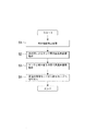
図1は、一実施の形態に係るウォータサーバの高温水循環処理の構成例を示している。図1に示す構成は一例であり、係る構成に本発明が限定されるものではない。
このウォータサーバ2は、給水タンク4から供給される水Wを加熱もしくは冷却することで、温水や冷水を供給する装置の一例であり、たとえば図1に示すように、第1のタンク6、第2のタンク8、給水タンク4と接続する給水管10、タンク側から給水管10に合流する還流管12、第1のタンク6と第2のタンク8との間に接続される通水管14とバイパス管16を備える。給水管10には、ポンプ18を備えるほか、還流管12との接続を切替える3方弁20が設置される。そのほかウォータサーバ2には、ポンプ18の駆動制御や図示しない加熱手段や冷却装置の制御を行う制御部22を備える。
[One Embodiment]
FIG. 1 shows a configuration example of a high temperature water circulation treatment of a water server according to an embodiment. The configuration shown in FIG. 1 is an example, and the present invention is not limited to such a configuration.
The
このウォータサーバ2は、たとえば通常の温水や冷水を供給する給水機能に対し、タンク内で高温水を循環させるとともに、給水管10や還流管12に対してタンク側から高温水を流して内部を清浄化する高温水循環機能を備える。ウォータサーバ2では、高温水循環処理において、第1のタンク6と第2のタンク8の間で高温水を循環させる第1の循環路を形成するとともに、タンクから給水管10側や還流管12に高温水を流し、再びタンク側に高温水を戻す第2の循環路が形成される。
The
給水タンク4は、常温またはそれに近い水Wを貯留し、ウォータサーバ2の給水または給湯により消費した分の水Wを第1のタンク6側に供給する給水手段の一例である。この給水タンク4は、たとえばプラスチックやビニール、樹脂材料で形成される容器であり、水Wを取り出す部分には外部から雑菌や空気などの接触を遮断する図示しないアタッチメントを備えてもよい。
第1のタンク6と第2のタンク8は、内部に水Wを溜め、給水要求に応じて湯または冷水を供給する手段の一例であって、たとえば図示しない冷却装置やヒータのいずれかを備えている。第1のタンク6は、たとえば給水タンク4よりも高い位置に配置され、タンクの上部側に接続した給水管10を通じて、給水タンク4内の水Wが流入する。第2のタンク8は、第1のタンク6よりも低い位置に配置され、第1のタンク6を介して水Wが流入する。ウォータサーバ2では、第1のタンク6と第2のタンク8において、加熱処理または冷却処理によりそれぞれ所定温度の冷水または温水に加工して、外部に給水する。
給水管10は、給水タンク4内の水Wを流す管路であって、一端が給水タンク4に接続され、他端側が第1のタンク6に接続される。給水管10は、たとえば給水タンク4から第1のタンク6までの配置高さにより管路長が決まる。
還流管12は、高温水循環動作において、タンク側の高温水を給水管10側に流す管路の一例であり、第2の循環路を構成する。還流管12は、一端がタンク側に接続され、他端側が3方弁20を介して給水管10の一部に接続されており、この3方弁20によって給水管10に対して流路の接続と遮断が切替えられる。
The
The
The
The
通水管14は、第1のタンク6から第2のタンク8に対して水Wを流す管路の一例である。バイパス管16は、高温水循環動作時に通水管14と合せて第1のタンク6と第2のタンク8との間で循環路を形成する管路の一例であり、図示しない弁によって高温水循環動作時のみ開状態とする。
The
制御部22は、ウォータサーバ2のヒータや冷却装置の動作制御機能を実行するほか、高温水循環動作において第1の循環路と第2の循環路の形成処理、ポンプ動作制御、高温水循環処理の状態監視処理などを実行する。
The
<高温水循環動作制御>
図2は、高温水循環動作の制御処理の一例を示している。図2に示す処理内容、処理手順は一例であり、これに本発明が限定されない。この高温水循環動作制御の処理は、ウォータサーバ2に搭載されるコンピュータにより実行される。
制御部22は、給水機能停止処理を実行し(S1)、通常運転である冷水または温水の供給を禁止させる。この、給水機能停止処理は、ウォータサーバ2の高温水循環動作の開始タイミングとして設定された時刻またはウォータサーバ2の利用状態等の条件に基づいて開始される。すなわち、制御部22は、たとえば週または月毎の一定期間が経過しているか否かの経過期間条件や、ユーザーが給水利用しない深夜や日中の勤務時間帯などの時刻などの実行開始条件などに基づいて、高温水循環動作の開始タイミングを監視すればよい。
給水機能の停止処理が完了すると、熱対流によるタンク間の高温水循環処理を実行する(S2)。この処理は高温水循環の第1段階の処理であり、バイパス管16を開状態にして、第1のタンク6と第2のタンク8との間に第1の循環路を形成するとともに、ヒータを高温水循環動作モードに設定してタンク内の水を清浄化処理に必要な所定温度に加熱する。所定温度に加熱された高温水hHWは、通水管14とバイパス管16を通じて第1のタンク6と第2のタンク8の間を内部の水の温度差により自然循環する。図1では通水管14を通じて第1のタンク6から第2のタンク8に高温水hHWが流れ、バイパス管16を通じて第2のタンク8から第1のタンク6に高温水hHWが流れるように示しているがこれに限らず、循環の方向が逆になる場合もある。また、通水管14、バイパス管16の内部において、それぞれの内部で循環が発生する場合も含まれる。
<High temperature water circulation operation control>
FIG. 2 shows an example of the control process of the high temperature water circulation operation. The processing content and processing procedure shown in FIG. 2 are examples, and the present invention is not limited thereto. This high-temperature water circulation operation control process is executed by the computer mounted on the
The
When the stop treatment of the water supply function is completed, the high temperature water circulation treatment between the tanks by heat convection is executed (S2). This process is the first stage process of high temperature water circulation, in which the
熱対流によるタンク間の高温水循環の後、タンクと給水管10との間で高温水循環処理を行う(S3)。この処理は、高温水循環の第2段階の処理であり、第1のタンク6または第2のタンク8のいずれか、もしくは両方を高温水hHWの供給源とし、還流管12を通じて給水管10内を高温水hHWで満たす。このとき3方弁20は、給水タンク4側から還流管12側に切替えられ、給水管10と還流管12が通水状態となり、給水タンク4側への高温水hHWの流入を阻止する。高温水循環動作として、ポンプ18を所定の回転数で動作させることで、タンク側から高温水hHWが給水管10側に流入し、給水管10に滞留している水Wがタンク側に流される。
清浄化処理に必要な所定時間が経過すると、制御部22は、高温水循環モードから給水モードに切替えて(S4)、高温水循環処理を終了する。
After the high temperature water circulation between the tanks by heat convection, the high temperature water circulation treatment is performed between the tank and the water supply pipe 10 (S3). This treatment is a second stage treatment of the high temperature water circulation, in which either or both of the
When the predetermined time required for the cleaning process elapses, the
<一実施の形態の効果>
一実施の形態によれば次のような効果が得られる。
(1) 冷水や常温の水Wが接触するタンクや管路内を高温水によって清浄化することができる。
(2) 容積の大きいタンク間での高温水循環処理に熱対流による循環を利用することで、ポンプの駆動時間を減らすことができ、省エネ化できる。
(3) ポンプの駆動時間を軽減することで、高温水循環動作時の騒音や振動の発生時間が少なくなり、深夜帯に高温水循環動作を行う場合などに周囲環境に対する影響を減らすことができる。
(4) また、高温水循環動作でのポンプの動作時間を減らすことで、ポンプの動作寿命を延ばすことができる。
<Effect of one embodiment>
According to one embodiment, the following effects can be obtained.
(1) The inside of tanks and pipelines that come into contact with cold water or normal temperature water W can be cleaned with hot water.
(2) By using heat convection circulation for high-temperature water circulation treatment between tanks with a large volume, the driving time of the pump can be reduced and energy can be saved.
(3) By reducing the driving time of the pump, the noise and vibration generation time during the high temperature water circulation operation can be reduced, and the influence on the surrounding environment can be reduced when the high temperature water circulation operation is performed at midnight.
(4) In addition, the operating life of the pump can be extended by reducing the operating time of the pump in the high-temperature water circulation operation.
<ウォータサーバ30>
図3は、実施例1に係るウォータサーバ30の構成例を示している。図3において、図1と共通部分には同一符号を付してある。
このウォータサーバ30には、たとえば装置の最下層側に給水タンク32を備えている。この給水タンク32には、たとえば紙やプラスチック、その他金属製などの外装ケース34の内部に収縮可能なプラスチック製の給水容器36が収納されている。水Wは給水容器36内に空気を抜いて充填されており、ウォータサーバ30への給水に応じて負圧となり、給水容器36が収縮していく。給水容器36には、たとえば一部に給水口38が形成されている。
ウォータサーバ30の給水部分には、たとえば給水管の一部であって、給水容器36側と接続する管路42を備える。この管路42は、たとえば樹脂等で構成され、可動可能となっている。管路42は、たとえば一端側に、給水容器36の給水口38と接合するとともに、給水容器36側に外部から空気や水の流入を阻止する逆止弁40を含むアタッチメントを備える。また管路42の他端側は、3方弁20に接続する。管路42を通じて給水タンク32から取り込んだ水Wは、給水管44を通じて冷水タンク50に流される。
給水管44には、たとえば3方弁20の近くに、給水タンク32に対して負圧をかけて水Wを取出し、給水管44内に水Wを圧送させるポンプ18が設置される。
<
FIG. 3 shows a configuration example of the
The
The water supply portion of the
In the
<冷水タンク50>
ウォータサーバ30は、たとえば本体の上部側に冷水タンク50が配置され、下段に温水タンク52が設置されている。冷水タンク50は本発明の第1のタンク、温水タンク52は、本発明の第2のタンクの一例である。この冷水タンク50および温水タンク52は、それぞれ設定温度に温度管理されて、冷水CWまたは温水HWを貯留する。
冷水タンク50は、たとえば内部にタンク内径よりも小さい径の仕切り板54を備えている。この仕切り板54は、冷水タンク50の中程の高さに配置されており、タンクの底部側に滞留する水とタンクの上部側の水とを仕切る。また、仕切り板54は、中心側に所定の径の開口部56が形成されおり、この開口部56を通じて温水タンク52に繋がる通水管58が接続されている。この通水管58は、冷水タンク50内の水を温水タンク52側に流す管路であり、冷水タンク50の底部を通過して温水タンク52の下層側に水Wまたは冷水CWを流す。
また冷水タンク50は、温水タンク52と接続するバイパス管60を備えている。バイパス管60は、通水管58と並列に設置されており、高温水循環動作時に通水するためのバイパス弁62を備えている。すなわち、バイパス弁62は、通常の給水運転時は閉状態に維持されており、冷水タンク50と温水タンク52との間で温水HWや冷水CWのバイパス管60の通水が阻止される。
冷水タンク50の外壁部には冷却装置66の蒸発器(evaporator)64が備えられ、冷水タンク50に供給された水Wが冷却され、冷水CWに冷水化される。冷却装置66は、冷却器などを含む冷却サイクルを備える。また冷水タンク50には、貯留する冷水CWの温度管理手段として、温度センサ68を備えている、この温度センサ68は、たとえばサーミスタ温度計などを用いればよく、検出した温度は、制御装置として機能する制御基板100に通知される。
そのほか、冷水タンク50には、給水量を監視するための水位センサ70を備えている。水位センサ70は、たとえば天井側から所定の高さに配置された共通電極と単数または配置高さを異ならせた複数本の水位電極を利用すればよい。水位電極の通電状態が制御基板100に取り込まれ、所定水位になるまでポンプ18を動作させるようにすればよい。
<
In the
The
Further, the
An
In addition, the
<温水タンク52>
温水タンク52には、外部周囲にヒータ72が巻き付けられ、内部の水を設定温度としてたとえば85〜90〔℃〕に加熱している。このヒータ72は、たとえば電熱式ヒータなどが用いられる。
また温水タンク52は、たとえば底部側に、温水タンク52内の湯を通水させる還流管98を備える。この還流管98は3方弁20に接続される。還流管98は、給水処理において管路42や給水管44と遮断されており、高温水循環動作において3方弁20の切替えにより還流管98が給水管44と接続する。すなわち還流管98は、高温水循環動作において、タンク側と給水管44との間に形成する循環路の一部として機能する。
そのほか温水タンク52には、タンク内の温度を監視する温度センサ74や空だき安全装置などが備えられている。温度センサ74で検出された温度情報は制御基板100に通知され、温水温度管理などに利用される。また空だき安全装置は、温水タンク52内に水があるか否かを検出する手段であって、たとえば水位センサや水圧センサなどを備えてもよい。空だき安全装置は、検出した情報を制御基板100に通知して、制御基板100からの制御指示に従い、または制御基板100とは独立してヒータ72を強制的にOFFにする機能を備えてもよい。
<
A
Further, the
In addition, the
<給水の構成>
冷水タンク50の底部側には冷水管80が接続され、冷水タンク50内の冷水CWが給水口82側に流される。この冷水管80には、管路途中に冷水電磁弁84が設置されており、冷水タンク50からの給水のON/OFFや流量を切替える。
温水タンク52には、たとえば上部側に温水管90が接続され、給水の要求に応じて、温水タンク52内の温水HWが給水口92側に流される。この温水管90には、管路途中に温水電磁弁94が設置されており、温水タンク52からの給水のON/OFFや流量を切替える。
<Composition of water supply>
A
A
<制御部の構成>
ウォータサーバ30には、給水制御や高温水循環動作を制御する制御装置として制御基板100を備える。この制御基板100は、本発明の制御部の一例であり、ウォータサーバ30のポンプ18や3方弁20、冷却装置66やヒータ72などの機能部、温度センサ68、74や水位センサ70などの監視機能部と電気的に接続している。この制御基板100は、各機能部に対して運転動作指示を出力するとともに、各機能部から状態情報を収集する。また、制御基板100は、給水および給湯の操作、温度表示、温度設定などの操作手段や状態表示手段を備える操作パネル102と接続している。この操作パネル102には、少なくとも冷水スイッチ104、温水スイッチ106、ロック解除スイッチ108を備える。
そのほか、制御基板100は、給水管44に設置された流水センサ110の検出信号を取込み、給水状態または高温水循環状態の監視に利用してもよい。
<Structure of control unit>
The
In addition, the
図4は、ウォータサーバの制御部の構成例を示している。
制御基板100は、たとえばマイクロコンピュータなどで構成されており、プロセッサ112、メモリ部114、マルチタイマー116、I/O(Input/Output)118などを備えている。
プロセッサ112は、たとえばCPU(Central Processing Unit )で構成され、メモリ部114に記憶されているOS(Operating System)や水の冷却制御、加熱制御、給水制御のほか、高温水循環などの運転モードに関する制御プログラムなどの演算処理を行う。またプロセッサ112は、ウォータサーバ30のヒータ72や弁などの各機能部の状態情報を監視する状態監視処理を実行する。メモリ部114は、たとえばROM(Read Only Memory)などで構成されるプログラムの記憶領域であるプログラム記憶部や、収集データなどを保存するデータ記憶部、制御プログラムおよび情報処理プログラムの演算が行われるワークエリアとして機能するRAM(Random Access Memory)を備える。
FIG. 4 shows a configuration example of the control unit of the water server.
The
The
マルチタイマー116は、計時手段の一例であり、たとえば運転状態の時刻情報の記録・表示のほか、設定された時間間隔を計時する機能、操作入力や運転状態の切替えなどの発生した事象間の経過時間を計時し、記録する機能を備える。このマルチタイマー116は、高温水循環動作において、たとえばポンプ18の駆動時間を計時する配管タイマーとして機能するほか、清浄化処理として高温水hHWを滞留させる時間を計時する高温維持タイマーとして機能する。
The multi-timer 116 is an example of a timekeeping means. For example, in addition to recording / displaying time information of an operating state, a function of measuring a set time interval, an operation input, a switching of an operating state, and the like are elapsed between events. It has a function to time and record time. In the high-temperature water circulation operation, the multi-timer 116 functions as, for example, a piping timer that measures the driving time of the
I/O118は、ウォータサーバ30の各機能部と制御基板100との間のインターフェースの一例である。制御基板100は、I/O118を介して、冷水電磁弁84、温水電磁弁94、バイパス弁62、温度センサ68、74、冷却装置66、ヒータ72、ポンプ18、3方弁20等と接続する。また制御基板100は、たとえば操作パネル102と接続しており、省エネスイッチ120、冷水スイッチ104、温水スイッチ106、ロック解除スイッチ108に対する操作入力を受けて各処理を実行するとともに、繰返し設定ランプ121、省エネ中ランプ122、温水ランプ123、高温ランプ124、ロック解除ランプ125、冷水ランプ126、弱冷ランプ127、高温循環ランプ128を表示させる。
The I /
<高温水循環動作1>
図5は、高温水循環動作1の状態例を示している。
この高温水循環動作1では、既述のように、タンク間の熱対流による循環動作の一例である。給水動作モードから高温水循環動作モードに移行すると、制御基板100からの指示により、冷却装置66をOFF状態とし、冷水電磁弁84、温水電磁弁94をロックするとともに、バイパス弁62を開状態にする。これにより冷水タンク50と温水タンク52は、通水管58とバイパス管60により通水状態となる。また制御基板100は、たとえば高温水循環動作としてヒータ72を動作させてタンク内の水または湯を加熱して所定温度の高温水hHWを生成させる。この高温水hHWは、清浄化の対象である冷水タンク50や通水管58、還流管98、給水管44内が清浄化温度Tとして、たとえば85〔℃〕以上となるように温度が設定される。この高温水hHWは、たとえば清浄化温度Tの条件を満たしていれば、給水処理における温水タンク52内の温水HWと同じ温度に制御してもよい。
バイパス弁62を開状態に切替えると、冷水タンク50内の冷水CWと温水タンク52内の高温水hHWまたは温水HWとの温度差により通水管58とバイパス管60を通じて熱移動による対流が発生し、冷水タンク50の冷水CWが温水タンク52に流れ加熱される。この高温水循環動作1の実行中、制御基板100は、温度センサ68、74の検出温度を監視し、その温度に応じてヒータ72の加熱制御を行う。
冷水タンク50内の検出温度がたとえば清浄化温度Tに達すると、高温水循環動作1から高温水循環動作2に移行する。
<High temperature water circulation operation 1>
FIG. 5 shows an example of the state of the high temperature water circulation operation 1.
As described above, the high-temperature water circulation operation 1 is an example of a circulation operation due to heat convection between tanks. When the mode shifts from the water supply operation mode to the high temperature water circulation operation mode, the
When the
When the detected temperature in the
<高温水循環動作2>
図6は、高温水循環動作2の状態例を示している。
この高温水循環動作2は、既述のように、タンクと給水管44との間の高温水循環動作の一例である。
高温水循環動作2に移行すると、還流管98と給水管44を接続状態としてタンクとの間で第2の循環路を形成し、ポンプ18の動作を開始する。このとき、バイパス弁62は開状態に維持すればよく、または閉止してもよい。
ポンプ18を動作させると、給水管44内の水Wが冷水タンク50内に流入し、温水タンク52内の高温水hHWが還流管98を通じて給水管44内に流れ込む。制御基板100は、たとえば温度センサ68、74の検出温度監視やポンプ18の回転制御を行い、所定の清浄化時間tとして、30〔分〕以上が経過するまで高温水循環動作2を行う。
<High temperature
FIG. 6 shows a state example of the high temperature
As described above, the high temperature
When the process shifts to the high temperature
When the
<高温水循環動作>
図7は、高温水循環動作の処理手順の一例を示している。図7に示す処理内容、処理手順は一例であり、これに本発明が限定されない。
制御基板100は、高温水循環動作モードに移行すると、冷水タンク50側の冷却機能を停止させる(S11)とともに、温水タンク52側の温水管理機能を継続させる(S12)。高温水循環動作モードへの移行は、たとえばウォータサーバ30に予め設定された時間情報として、深夜帯などの設定時刻や、使用開始からの経過時間などが利用される。また、制御基板100は、たとえばユーザー毎の使用頻度や使用時間帯などを自動で学習し、ユーザーの使用頻度が少ない時間を高温水循環実行時間として設定してもよい。
制御基板100は、3方弁20を還流管98側に切替え(S13)、バイパス弁62を開状態として冷水タンク50と温水タンク52間の循環動作を開始させる(S14)。すなわち、高温水循環動作1である冷水タンク50の高温化を実行する。このとき、ポンプ18は停止状態を維持させることで、高温水hHWは、冷水タンク50やバイパス管60、通水管58に流れるほか、還流管98側に流れてもよい。
<High temperature water circulation operation>
FIG. 7 shows an example of the processing procedure of the high temperature water circulation operation. The processing content and processing procedure shown in FIG. 7 are examples, and the present invention is not limited thereto.
When the
The
高温水循環動作1の状態監視として、冷水タンク50内の温度が清浄化温度Tである、85〔℃〕以上になるまで待機する(S15のNO)。検出温度が85〔℃〕に達すると(S15のYES)、高温水循環動作2である配管高温化処理に移行する。すなわち制御基板100は、ポンプ18の駆動を開始し(S16)、マルチタイマー116を動作させ、配管タイマーと高温維持タイマーをスタートさせる(S17)。
制御基板100は、マルチタイマー116の計時により配管タイマーがタイムアップするまで待機し(S18のNO)、タイムアップすると(S18のYES)、ポンプ18の駆動を停止させる(S19)。配管タイマーは、たとえば還流管98や給水管44の容積、およびポンプ18による循環量などに応じてタイムアップ時間を設定すればよい。すなわち、給水管44や還流管98の容積が小さい場合や、ポンプ18の循環量が大きい場合には、還流管98や給水管44内に高温水hHWが満たされるまでの時間が少なくなるため、ポンプ18の駆動時間を減らすことができる。
また、制御基板100は、マルチタイマー116の計時により高温維持タイマーがタイムアップするまで待機し(S20のNO)、タイムアップすると(S20のYES)、バイパス弁62を閉止させる(S21)。
そして、高温水循環動作の終了処理として、3方弁20を給水側に切替え(S22)、給水動作である通常状態に移行する(S23)。
As a condition monitoring of the high temperature water circulation operation 1, the
The
Further, the
Then, as the termination process of the high temperature water circulation operation, the three-
<実施例1の効果>
斯かる構成によれば、次のような効果が得られる。
(1) 冷水や常温の水Wが接触するタンクや管路内を高温水によって清浄化することができる。
(2) 容積の大きいタンク間での高温水循環処理に熱対流による循環を利用することで、ポンプの駆動時間を減らすことができ、省エネ化できる。
(3) ポンプの駆動時間を軽減することで、高温水循環動作時の騒音や振動の発生時間が少なくなり、深夜帯に高温水循環動作を行う場合などに周囲環境に対する影響を減らすことができる。
(4) また、高温水循環動作でのポンプの動作時間を減らすことで、ポンプの動作寿命を延ばすことができる。
(5) 高温水循環対象である給水管や還流管側に対する流入量を予め算出し、時間的管理によってポンプの動作制御を行うことで、給水管側に温度センサを備える必要がなく、部品数の削減や監視処理の軽減が図れる。
(6) 管路の小さい通水管やバイパス管を利用し、熱対流による高温水循環動作1を先に行うことで、温水タンク内の湯の温度変化が抑えられ、ヒータに急激な加熱動作をさせることがなく、装置の消耗を抑えることができる。
<Effect of Example 1>
According to such a configuration, the following effects can be obtained.
(1) The inside of tanks and pipelines that come into contact with cold water or normal temperature water W can be cleaned with hot water.
(2) By using heat convection circulation for high-temperature water circulation treatment between tanks with a large volume, the driving time of the pump can be reduced and energy can be saved.
(3) By reducing the driving time of the pump, the noise and vibration generation time during the high temperature water circulation operation can be reduced, and the influence on the surrounding environment can be reduced when the high temperature water circulation operation is performed at midnight.
(4) In addition, the operating life of the pump can be extended by reducing the operating time of the pump in the high-temperature water circulation operation.
(5) By calculating the inflow amount to the water supply pipe and the return pipe side, which are the targets of high-temperature water circulation, and controlling the operation of the pump by time management, it is not necessary to equip the water supply pipe side with a temperature sensor, and the number of parts Reduction and monitoring processing can be reduced.
(6) By using a water pipe or bypass pipe with a small pipeline and performing the high-temperature water circulation operation 1 by heat convection first, the temperature change of the hot water in the hot water tank is suppressed, and the heater is made to perform a rapid heating operation. It is possible to reduce the consumption of the device.
<ウォータサーバ30>
図8は、実施例2に係るウォータサーバ30の構成例を示している。図8において、図3と共通部分には同一符号を付してある。
実施例1のウォータサーバ30では、高温水を給水管44側に流す還流管を温水タンク52に接続する構成を示しているが、斯かる還流管は、他の管路から高温水hHWを取り込んで給水管44側に流してもよい。
実施例2のウォータサーバ30では、たとえば図8に示すように、冷水管80の一部に還流管130の一端が接続され、その他端側が3方弁20に接続される。
このウォータサーバ30では、既述のように、給水管44を通じて冷水タンク50側に水Wが供給され、冷水タンク50内で冷水CWが生成されるとともに、温水タンク52で温水HWが生成される。給水要求があった場合、冷水電磁弁84が開状態となり、冷水管80を通じて給水口82から冷水CWを流出させる。このとき還流管130は、たとえば冷水タンク50から流入した水Wまたは冷水CWで満たされている。還流管130の他端側は、3方弁20が閉状態となっていることから、管路42や給水管44側と還流管130との間で水の流入や流出は生じない。
<
FIG. 8 shows a configuration example of the
The
In the
In the
<高温水循環動作2>
図9は、実施例2に係る高温水循環動作2の状態例を示している。
冷水タンク50と温水タンク52との間で高温水循環動作1が完了すると、ポンプ18を動作させて高温水循環動作2に移行する。
実施例2では、高温水hHWを循環させる第2の循環路として、冷水管80、還流管130、給水管44が含まれる。冷水管80は、冷水タンク50や還流管130に対して常に通水状態である。そのため高温水循環動作1において、冷水タンク50内が高温水hHWで満たされているので、高温水循環動作2により冷水管80や還流管130内の水も高温化する。
<High temperature
FIG. 9 shows a state example of the high temperature
When the high temperature water circulation operation 1 is completed between the
In the second embodiment, the
このような構成において、制御基板100は、実施例1の高温水循環動作の処理手順と同様の制御を行えばよい。すなわち、制御基板100は、高温水循環動作モードに移行すると、冷水タンク50側の冷却機能を停止させるとともに、温水タンク52側の温水管理機能を継続させる。制御基板100は、3方弁20を還流管130側に切替え、バイパス弁62を開状態として冷水タンク50と温水タンク52間の循環動作を開始させる。
高温水循環動作1により、冷水タンク50内の温度が清浄化温度Tである、85〔℃〕以上になるまで待機し、検出温度が85〔℃〕に達すると高温水循環動作2である配管高温化処理に移行する。制御基板100は、配管高温化処理として、配管タイマーの計時、冷水タンク50の高温維持として高温維持タイマーの計時を行えばよい。
そして制御基板100は、高温維持タイマーがタイムアップすると、バイパス弁62を閉止させるとともに、3方弁20を給水側に切替えて通常状態に移行する。
In such a configuration, the
By the high temperature water circulation operation 1, the temperature in the
Then, when the high temperature maintenance timer expires, the
<実施例2の効果>
実施例2によれば、次のような効果が得られる。
(1) 実施例1の効果と同様の効果を発揮することができる。
(2) さらに、冷水CWが流れる冷水管80を高温水循環処理の循環路に含むことで、ウォータサーバの清浄機能の向上が図れる。
(3) 冷水管80に対する滅菌手段を別途設ける必要がなく、部品数の軽減が図れる。
<Effect of Example 2>
According to the second embodiment, the following effects can be obtained.
(1) The same effect as that of Example 1 can be exhibited.
(2) Further, by including the
(3) It is not necessary to separately provide a sterilizing means for the
<高温水循環動作2>
図10は、実施例3に係る高温水循環動作2の処理手順の一例を示している。
実施例1、2の高温水循環動作2では、ポンプ18の動作制御としてマルチタイマー116を利用した配管タイマーの計時処理を行い、配管タイマーのタイムアップによりポンプ18を停止させる処理を行っている。これに対しこの実施例3では、マルチタイマー116を利用して高温維持タイマーのタイムアップのみを計時する場合を示している。
この処理手順では、図10に示すように、制御基板100は、高温水循環動作モードに移行すると、冷水タンク50側の冷却機能を停止させる(S31)とともに、温水タンク52側の温水管理機能を継続させる(S32)。制御基板100は、3方弁20を還流管98、130側に切替え(S33)、バイパス弁62を開状態として冷水タンク50と温水タンク52間の循環動作を開始させる(S34)。
<High temperature
FIG. 10 shows an example of the processing procedure of the high temperature
In the high-temperature
In this processing procedure, as shown in FIG. 10, when the
高温循環動作1の状態監視として、冷水タンク50内の温度が清浄化温度Tである、85〔℃〕以上になるまで待機する(S35のNO)。検出温度が85〔℃〕に達すると(S35のYES)、高温水循環動作2である配管高温化処理に移行する。すなわち制御基板100は、ポンプ18の駆動を開始し(S36)、マルチタイマー116を動作させ、高温維持タイマーをスタートさせる(S37)。
制御基板100は、マルチタイマー116の計時により高温維持タイマーがタイムアップするまで待機し(S38のNO)、タイムアップすると(S38のYES)、ポンプ18の駆動を停止させるとともにバイパス弁62を閉止させる(S39)。そして、高温水循環動作の終了処理として、3方弁20を給水側に切替え(S40)、給水動作である通常状態に移行する(S41)。
As a condition monitoring of the high temperature circulation operation 1, wait until the temperature in the
The
<実施例3の効果>
斯かる構成によれば、次のような効果が得られる。
(1) 実施例1、2の効果と同様の効果を発揮することができる。
(2) 高温水循環処理において高温水の循環を維持するので、清浄化の対象である給水管44や還流管98、130内の温度が低下するのを防止できる。
(3) 清浄化対象の管路内に温度センサを設けなくとも、冷水タンク50内の高温水の温度を監視することで、清浄化温度Tの高温水hHWで満たされているか否かを監視でき、清浄化処理の信頼性を高めることができる。
<Effect of Example 3>
According to such a configuration, the following effects can be obtained.
(1) The same effect as that of Examples 1 and 2 can be exhibited.
(2) Since the circulation of high-temperature water is maintained in the high-temperature water circulation treatment, it is possible to prevent the temperature in the
(3) By monitoring the temperature of the high-temperature water in the
〔他の実施の形態〕
以上説明した実施の形態について、その特徴事項や変形例を以下に列挙する。
(1) 高温水循環動作の制御処理として、給水管44側に温度センサを設置して温度管理してもよい。この温度管理では、たとえば清浄化の設定条件とした清浄化温度Tで所定時間tを維持するため、多段階のしきい値を設定し、そのしきい値に応じてポンプ制御やヒータ制御を行ってもよい。
(2) 高温維持タイマーの計時処理についてポンプ動作開始からスタートしているが、給水管44の温度が所定温度tになった時に計時をスタートしてもよい。また、給水管44内部の温度が清浄化温度T未満となったときには、計時を中断し、清浄化温度Tに達したときに再スタートしてもよい。さらに、清浄化温度Tの条件に達しない温度まで低下した場合には、計時をリセットして清浄化処理をやり直す処理や、清浄化が適切に行えなかったことの記録処理および報知機能を備えてもよい。
(3) ウォータサーバ30は、たとえば温水タンク52の底部側に排水管路を備えてもよい。この排水管路は、たとえばメンテナンス時の排水または通常運転時の不要水を排出する手段の一例であって、管路上に排水弁を備えている。この排水弁は、たとえば制御基板100と電気的に接続されており、高温水循環動作の完了時に制御基板100からの開閉指示によって動作させてもよい。
[Other Embodiments]
The features and modification examples of the embodiments described above are listed below.
(1) As a control process for the high temperature water circulation operation, a temperature sensor may be installed on the
(2) Timekeeping of the high temperature maintenance timer Although the pump operation starts, the timekeeping may be started when the temperature of the
(3) The
(4) 上記実施例1、2、3では、ウォータサーバの第1のタンクを冷水タンク50とし、第2のタンクを温水タンク52とする場合を示したがこれに限らない。上部側に第1のタンクとして温水タンク52を配置し、下部側に第2のタンクとして冷水タンク50を備えてもよい。
(5) 高温水循環動作では、ヒータ72やポンプ18を連続運転させる場合を示したがこれに限らない。制御基板100は、たとえば温度センサ68、74の検出温度に基づいて、高温水hHWの温度が所定の清浄化温度Tに達している場合に、ヒータ72やポンプ18のいずれかまたは両方を所定時間毎に間欠運転させてもよい。そして、制御基板100は、高温水hHWの温度が低下した場合には、所定時間または高温水hHWが所定温度に達するまでヒータ72やポンプ18のいずれかまたは両方を動作させるように制御してもよい。
(6) 上記実施の形態および実施例では、還流管12、98と給水管10、44側とを遮断し、または切替える手段として3方弁20を利用する場合を示したがこれに限らない。斯かる切替えおよび遮断手段として、複数の2方弁、開閉弁、電磁弁などを利用してもよい。
(4) In Examples 1, 2 and 3, the case where the first tank of the water server is a
(5) In the high-temperature water circulation operation, the case where the
(6) In the above embodiments and examples, the case where the three-
以上説明したように、本発明の最も好ましい実施の形態等について説明した。本発明は、上記記載に限定されるものではない。特許請求の範囲に記載され、または発明を実施するための形態に開示された発明の要旨に基づき、当業者において様々な変形や変更が可能である。斯かる変形や変更が、本発明の範囲に含まれることは言うまでもない。
As described above, the most preferable embodiment of the present invention has been described. The present invention is not limited to the above description. Various modifications and modifications can be made by those skilled in the art based on the gist of the invention described in the claims or disclosed in the form for carrying out the invention. Needless to say, such modifications and modifications are included in the scope of the present invention.
本発明のウォータサーバは、第1のタンクと第2のタンク間で熱対流による高温水循環をした後に、給水管路側の循環路に対してポンプによる高温水循環を行うことで、高温水循環動作における省エネ化や騒音・振動を抑えることができるなど、有用である。
The water server of the present invention circulates high-temperature water by heat convection between the first tank and the second tank, and then circulates high-temperature water by a pump to the circulation path on the water supply pipeline side to save energy in the high-temperature water circulation operation. It is useful because it can suppress noise and vibration.
2、30 ウォータサーバ
4、32 給水タンク
6 第1のタンク
8 第2のタンク
10、44 給水管
12、98、130 還流管
14、58 通水管
16、60 バイパス管
18 ポンプ
20 3方弁
22 制御部
34 外装ケース
36 給水容器
38 給水口
40 逆止弁
42 管路
50 冷水タンク
52 温水タンク
54 仕切り板
56 開口部
62 バイパス弁
64 蒸発器
66 冷却装置
68、74 温度センサ
70 水位センサ
72 ヒータ
80 冷水管
82 給水口
84 冷水電磁弁
90 温水管
92 給水口
94 温水電磁弁
100 制御基板
102 操作パネル
104 冷水スイッチ
106 温水スイッチ
108 ロック解除スイッチ
110 流水センサ
112 プロセッサ
114 メモリ部
116 マルチタイマー
118 I/O
120 省エネスイッチ
121 繰返し設定ランプ
122 省エネ中ランプ
123 温水ランプ
124 高温ランプ
125 ロック解除ランプ
126 冷水ランプ
127 弱冷ランプ
128 高温循環ランプ
2, 30
120 Energy saving switch 121 Repeat setting lamp 122 Energy saving
Claims (6)
給水タンクと、
前記給水タンクよりも高い位置に配置され、前記給水タンクから給水される第1のタンクと、
前記第1のタンクよりも下方に配置され、通水管を通じて前記第1のタンクから給水される第2のタンクと、
前記第1のタンクまたは前記第2のタンクに溜めた水を加熱する加熱手段と、
ポンプを備え、前記給水タンクから前記第1のタンクに水を流す給水管と、
前記通水管と並列に設置され、弁の開閉により前記第1のタンクと前記第2のタンクの間を通水させるバイパス管と、
前記給水管を含む循環路を形成する還流路と、
高温水循環処理の開始により前記バイパス管を開いて前記第1のタンクと前記第2のタンクとで第1の循環路を形成して、前記バイパス管を通じて前記加熱手段で所定温度に加熱した高温水を前記第1のタンクと前記第2のタンクの間で循環させ、前記高温水循環処理の実行時に高温水が流入する前記第1のタンクまたは前記第2のタンクの水温が所定温度に達したことを契機に前記ポンプを駆動させて、前記還流路から前記給水管に高温水を流入させ、前記還流路、前記給水管、前記第1のタンクおよび前記第2のタンクとからなる第2の循環路に高温水を循環させる制御部と、
を備えたことを特徴とするウォータサーバ。A water server that provides hot or cold water
Water tank and
A first tank that is located higher than the water supply tank and is supplied with water from the water supply tank,
A second tank, which is arranged below the first tank and is supplied with water from the first tank through a water pipe,
A heating means for heating the water stored in the first tank or the second tank, and
A water supply pipe provided with a pump to flow water from the water supply tank to the first tank,
A bypass pipe installed in parallel with the water pipe and allowing water to pass between the first tank and the second tank by opening and closing a valve.
A reflux path forming a circulation path including the water supply pipe and
When the high temperature water circulation treatment is started, the bypass pipe is opened to form a first circulation path between the first tank and the second tank, and the high temperature water heated to a predetermined temperature by the heating means through the bypass pipe. Was circulated between the first tank and the second tank, and the water temperature of the first tank or the second tank into which the hot water flows during the execution of the high temperature water circulation treatment has reached a predetermined temperature. the by the pump is driven in response, the flow Toe entering the hot water in the water supply pipe from the return channel, the return channel, the water supply pipe, the first tank and the second consisting of the second tank A control unit that circulates high-temperature water in the circulation path ,
A water server characterized by being equipped with.
前記制御部は、前記高温水循環処理の開始時または前記第1のタンクと前記第2のタンクの間で熱対流により高温水を循環させた後に、前記3方弁を切替えて、前記給水管と前記還流路を接続状態にすることを特徴とする、請求項1に記載のウォータサーバ。 One end of the reflux path is connected to the second tank, and the other end is connected to the water supply pipe via a three-way valve.
Wherein, after circulating the hot water by the heat convection between the beginning or the first tank and the second tank of the hot water circulation process, by switching the 3-way valve, and the water supply pipe The water server according to claim 1, wherein the return path is connected.
給水タンクと、
前記給水タンクよりも高い位置に配置され、前記給水タンクから給水される第1のタンクと、
前記第1のタンクよりも下方に配置され、通水管を通じて前記第1のタンクから給水される第2のタンクと、
前記第1のタンクまたは前記第2のタンクに溜めた水を加熱する加熱手段と、
ポンプを備え、前記給水タンクから前記第1のタンクに水を流す給水管と、
前記通水管と並列に設置され、弁の開閉により前記第1のタンクと前記第2のタンクの間を通水させるバイパス管と、
前記第1のタンクに溜めた温水または冷水を外部に流す給水管路と、
一端が該給水管路に接続され、他端が3方弁を介して前記給水管に接続され、前記給水管を含む循環路を形成する還流路と、
高温水循環処理の開始時または前記バイパス管を通じて前記加熱手段で所定温度に加熱した高温水を前記第1のタンクと前記第2のタンクの間で熱対流により循環させた後に、前記3方弁を切替えて前記給水管と前記還流路を接続状態にして、前記ポンプを駆動させて前記還流路から前記給水管に高温水を流す制御部と、
を備えたことを特徴とするウォータサーバ。 A water server that provides hot or cold water
Water tank and
A first tank that is located higher than the water supply tank and is supplied with water from the water supply tank,
A second tank, which is arranged below the first tank and is supplied with water from the first tank through a water pipe,
A heating means for heating the water stored in the first tank or the second tank, and
A water supply pipe provided with a pump to flow water from the water supply tank to the first tank,
A bypass pipe installed in parallel with the water pipe and allowing water to pass between the first tank and the second tank by opening and closing a valve.
A water supply line for flowing hot or cold water stored in the first tank to the outside ,
One end connected to the water supply pipe, the other end is connected to the water supply pipe via a three-way valve, a return path for forming a circulation path including the water supply pipe,
After allowed to Ri循ring by the heat convection between the hot water heated to a predetermined temperature by the heating means through the beginning or the bypass tube hot water circulation process of the first tank and the second tank, the 3-way valve and to the return path to the previous SL water supply pipe to the connection state is switched, and a control unit for the drives the pump flow hot water to the water supply pipe from the return path,
Features and to roux Otasaba further comprising a.
前記制御部は、該温度検出手段の検出温度が所定温度に達したことを契機に前記ポンプを駆動させて、高温水を前記還流路から前記給水管に流入させることを特徴とする、請求項1ないし請求項3のいずれかの請求項に記載のウォータサーバ。 A temperature detecting means for detecting the water temperature of the first tank or the second tank into which the hot water flows during the execution of the high temperature water circulation treatment is provided.
The control unit is characterized in that, when the detection temperature of the temperature detecting means reaches a predetermined temperature, the pump is driven to allow high-temperature water to flow into the water supply pipe from the recirculation path. The water server according to any one of claims 1 to 3.
前記制御部は、所定時間毎に前記ポンプの駆動をON/OFFさせることを特徴とする、請求項1ないし請求項4のいずれかの請求項に記載のウォータサーバ。 In addition, it has a timer to measure the elapsed time.
The water server according to any one of claims 1 to 4, wherein the control unit turns on / off the drive of the pump at predetermined time intervals.
Priority Applications (1)
| Application Number | Priority Date | Filing Date | Title |
|---|---|---|---|
| JP2017106331A JP6827367B2 (en) | 2017-05-30 | 2017-05-30 | Water server |
Applications Claiming Priority (1)
| Application Number | Priority Date | Filing Date | Title |
|---|---|---|---|
| JP2017106331A JP6827367B2 (en) | 2017-05-30 | 2017-05-30 | Water server |
Publications (2)
| Publication Number | Publication Date |
|---|---|
| JP2018203264A JP2018203264A (en) | 2018-12-27 |
| JP6827367B2 true JP6827367B2 (en) | 2021-02-10 |
Family
ID=64955012
Family Applications (1)
| Application Number | Title | Priority Date | Filing Date |
|---|---|---|---|
| JP2017106331A Active JP6827367B2 (en) | 2017-05-30 | 2017-05-30 | Water server |
Country Status (1)
| Country | Link |
|---|---|
| JP (1) | JP6827367B2 (en) |
Family Cites Families (5)
| Publication number | Priority date | Publication date | Assignee | Title |
|---|---|---|---|---|
| JP5520405B1 (en) * | 2013-03-18 | 2014-06-11 | 株式会社コスモライフ | Water server |
| JP2014201322A (en) * | 2013-04-02 | 2014-10-27 | 株式会社Brigeas | Water server |
| JP6368481B2 (en) * | 2013-11-14 | 2018-08-01 | Next Innovation合同会社 | Fluid storage and distribution device |
| JP2016199300A (en) * | 2015-04-13 | 2016-12-01 | 株式会社ウォーターダイレクト | Drink server |
| US20160362285A1 (en) * | 2015-06-09 | 2016-12-15 | George Yui | Bottom-loading bottled water dispensers with hot water sanitizing features |
-
2017
- 2017-05-30 JP JP2017106331A patent/JP6827367B2/en active Active
Also Published As
| Publication number | Publication date |
|---|---|
| JP2018203264A (en) | 2018-12-27 |
Similar Documents
| Publication | Publication Date | Title |
|---|---|---|
| JP4294624B2 (en) | Hot water storage water heater | |
| JP2007303726A (en) | Heat source device and its control method | |
| JP2007285653A (en) | Hot water supply device | |
| JP6827367B2 (en) | Water server | |
| JP5821002B2 (en) | Hot water system | |
| JP2021120305A (en) | Water refill control method, water server, and program | |
| JP5364243B2 (en) | Water heater | |
| JP5587358B2 (en) | Heat source device and control method thereof | |
| JP5326890B2 (en) | Thermal storage system | |
| JP2017137087A (en) | Water server, operation control method and operation control program thereof | |
| JP4379385B2 (en) | Water heater | |
| JP6623881B2 (en) | Hot water supply system | |
| JP2010078178A (en) | Hot water supply device | |
| JP2007178059A (en) | Heat pump type hot-water supply device | |
| JP2006145193A (en) | Refrigerator | |
| JP7011540B2 (en) | Hot water storage type hot water supply device | |
| JP4125610B2 (en) | Water heater | |
| JP2007278543A (en) | Water heater | |
| JP2011012911A (en) | Storage type water heater | |
| JP6770444B2 (en) | Water server, its information processing method and its information processing program | |
| JP7277750B2 (en) | bath equipment | |
| JP4635787B2 (en) | Hot water storage water heater | |
| JP2003254618A (en) | Hot water storage type hot water supply system | |
| JP2015094569A (en) | Floor heater display device | |
| JP2019007668A (en) | Refrigeration device |
Legal Events
| Date | Code | Title | Description |
|---|---|---|---|
| A621 | Written request for application examination |
Free format text: JAPANESE INTERMEDIATE CODE: A621 Effective date: 20191101 |
|
| A977 | Report on retrieval |
Free format text: JAPANESE INTERMEDIATE CODE: A971007 Effective date: 20200817 |
|
| A131 | Notification of reasons for refusal |
Free format text: JAPANESE INTERMEDIATE CODE: A131 Effective date: 20200825 |
|
| A521 | Request for written amendment filed |
Free format text: JAPANESE INTERMEDIATE CODE: A523 Effective date: 20201022 |
|
| TRDD | Decision of grant or rejection written | ||
| A01 | Written decision to grant a patent or to grant a registration (utility model) |
Free format text: JAPANESE INTERMEDIATE CODE: A01 Effective date: 20210105 |
|
| A61 | First payment of annual fees (during grant procedure) |
Free format text: JAPANESE INTERMEDIATE CODE: A61 Effective date: 20210119 |
|
| R150 | Certificate of patent or registration of utility model |
Ref document number: 6827367 Country of ref document: JP Free format text: JAPANESE INTERMEDIATE CODE: R150 |
|
| R250 | Receipt of annual fees |
Free format text: JAPANESE INTERMEDIATE CODE: R250 |