JP6827331B2 - Outer rotor type motor - Google Patents
Outer rotor type motor Download PDFInfo
- Publication number
- JP6827331B2 JP6827331B2 JP2017014501A JP2017014501A JP6827331B2 JP 6827331 B2 JP6827331 B2 JP 6827331B2 JP 2017014501 A JP2017014501 A JP 2017014501A JP 2017014501 A JP2017014501 A JP 2017014501A JP 6827331 B2 JP6827331 B2 JP 6827331B2
- Authority
- JP
- Japan
- Prior art keywords
- rotor
- hub
- yoke
- assembled
- top surface
- Prior art date
- Legal status (The legal status is an assumption and is not a legal conclusion. Google has not performed a legal analysis and makes no representation as to the accuracy of the status listed.)
- Expired - Fee Related
Links
Images


Classifications
-
- H—ELECTRICITY
- H02—GENERATION; CONVERSION OR DISTRIBUTION OF ELECTRIC POWER
- H02K—DYNAMO-ELECTRIC MACHINES
- H02K5/00—Casings; Enclosures; Supports
- H02K5/04—Casings or enclosures characterised by the shape, form or construction thereof
- H02K5/16—Means for supporting bearings, e.g. insulating supports or means for fitting bearings in the bearing-shields
- H02K5/173—Means for supporting bearings, e.g. insulating supports or means for fitting bearings in the bearing-shields using bearings with rolling contact, e.g. ball bearings
- H02K5/1737—Means for supporting bearings, e.g. insulating supports or means for fitting bearings in the bearing-shields using bearings with rolling contact, e.g. ball bearings radially supporting the rotor around a fixed spindle; radially supporting the rotor directly
-
- H—ELECTRICITY
- H02—GENERATION; CONVERSION OR DISTRIBUTION OF ELECTRIC POWER
- H02K—DYNAMO-ELECTRIC MACHINES
- H02K7/00—Arrangements for handling mechanical energy structurally associated with dynamo-electric machines, e.g. structural association with mechanical driving motors or auxiliary dynamo-electric machines
- H02K7/14—Structural association with mechanical loads, e.g. with hand-held machine tools or fans
- H02K7/16—Structural association with mechanical loads, e.g. with hand-held machine tools or fans for operation above the critical speed of vibration of the rotating parts
-
- F—MECHANICAL ENGINEERING; LIGHTING; HEATING; WEAPONS; BLASTING
- F04—POSITIVE - DISPLACEMENT MACHINES FOR LIQUIDS; PUMPS FOR LIQUIDS OR ELASTIC FLUIDS
- F04D—NON-POSITIVE-DISPLACEMENT PUMPS
- F04D29/00—Details, component parts, or accessories
- F04D29/26—Rotors specially for elastic fluids
- F04D29/32—Rotors specially for elastic fluids for axial flow pumps
- F04D29/325—Rotors specially for elastic fluids for axial flow pumps for axial flow fans
- F04D29/329—Details of the hub
-
- G—PHYSICS
- G11—INFORMATION STORAGE
- G11B—INFORMATION STORAGE BASED ON RELATIVE MOVEMENT BETWEEN RECORD CARRIER AND TRANSDUCER
- G11B19/00—Driving, starting, stopping record carriers not specifically of filamentary or web form, or of supports therefor; Control thereof; Control of operating function ; Driving both disc and head
- G11B19/20—Driving; Starting; Stopping; Control thereof
- G11B19/2009—Turntables, hubs and motors for disk drives; Mounting of motors in the drive
- G11B19/2045—Hubs
-
- H—ELECTRICITY
- H02—GENERATION; CONVERSION OR DISTRIBUTION OF ELECTRIC POWER
- H02K—DYNAMO-ELECTRIC MACHINES
- H02K1/00—Details of the magnetic circuit
- H02K1/06—Details of the magnetic circuit characterised by the shape, form or construction
- H02K1/22—Rotating parts of the magnetic circuit
- H02K1/27—Rotor cores with permanent magnets
- H02K1/2786—Outer rotors
- H02K1/2787—Outer rotors the magnetisation axis of the magnets being perpendicular to the rotor axis
- H02K1/2789—Outer rotors the magnetisation axis of the magnets being perpendicular to the rotor axis the rotor consisting of two or more circumferentially positioned magnets
- H02K1/2791—Surface mounted magnets; Inset magnets
-
- H—ELECTRICITY
- H02—GENERATION; CONVERSION OR DISTRIBUTION OF ELECTRIC POWER
- H02K—DYNAMO-ELECTRIC MACHINES
- H02K1/00—Details of the magnetic circuit
- H02K1/06—Details of the magnetic circuit characterised by the shape, form or construction
- H02K1/22—Rotating parts of the magnetic circuit
- H02K1/28—Means for mounting or fastening rotating magnetic parts on to, or to, the rotor structures
-
- H—ELECTRICITY
- H02—GENERATION; CONVERSION OR DISTRIBUTION OF ELECTRIC POWER
- H02K—DYNAMO-ELECTRIC MACHINES
- H02K21/00—Synchronous motors having permanent magnets; Synchronous generators having permanent magnets
- H02K21/02—Details
- H02K21/021—Means for mechanical adjustment of the excitation flux
- H02K21/022—Means for mechanical adjustment of the excitation flux by modifying the relative position between field and armature, e.g. between rotor and stator
- H02K21/023—Means for mechanical adjustment of the excitation flux by modifying the relative position between field and armature, e.g. between rotor and stator by varying the amount of superposition, i.e. the overlap, of field and armature
- H02K21/024—Radial air gap machines
-
- H—ELECTRICITY
- H02—GENERATION; CONVERSION OR DISTRIBUTION OF ELECTRIC POWER
- H02K—DYNAMO-ELECTRIC MACHINES
- H02K21/00—Synchronous motors having permanent magnets; Synchronous generators having permanent magnets
- H02K21/12—Synchronous motors having permanent magnets; Synchronous generators having permanent magnets with stationary armatures and rotating magnets
- H02K21/22—Synchronous motors having permanent magnets; Synchronous generators having permanent magnets with stationary armatures and rotating magnets with magnets rotating around the armatures, e.g. flywheel magnetos
-
- H—ELECTRICITY
- H02—GENERATION; CONVERSION OR DISTRIBUTION OF ELECTRIC POWER
- H02K—DYNAMO-ELECTRIC MACHINES
- H02K9/00—Arrangements for cooling or ventilating
- H02K9/02—Arrangements for cooling or ventilating by ambient air flowing through the machine
- H02K9/04—Arrangements for cooling or ventilating by ambient air flowing through the machine having means for generating a flow of cooling medium
- H02K9/06—Arrangements for cooling or ventilating by ambient air flowing through the machine having means for generating a flow of cooling medium with fans or impellers driven by the machine shaft
-
- H—ELECTRICITY
- H02—GENERATION; CONVERSION OR DISTRIBUTION OF ELECTRIC POWER
- H02K—DYNAMO-ELECTRIC MACHINES
- H02K1/00—Details of the magnetic circuit
- H02K1/06—Details of the magnetic circuit characterised by the shape, form or construction
- H02K1/22—Rotating parts of the magnetic circuit
- H02K1/28—Means for mounting or fastening rotating magnetic parts on to, or to, the rotor structures
- H02K1/30—Means for mounting or fastening rotating magnetic parts on to, or to, the rotor structures using intermediate parts, e.g. spiders
Landscapes
- Engineering & Computer Science (AREA)
- Power Engineering (AREA)
- Mechanical Engineering (AREA)
- General Engineering & Computer Science (AREA)
- Iron Core Of Rotating Electric Machines (AREA)
- Permanent Field Magnets Of Synchronous Machinery (AREA)
- Motor Or Generator Frames (AREA)
- Structures Of Non-Positive Displacement Pumps (AREA)
Description
本発明は、例えばHVAC(暖房、換気及び空調:Heating, Ventilation, and Air Conditioning)機器などに駆動源として用いられるアウターロータ型モータに関する。 The present invention relates to an outer rotor type motor used as a drive source in, for example, HVAC (Heating, Ventilation, and Air Conditioning) equipment.
空気流を発生させるインペラをモータにより回転駆動する空調装置には、ブラシ付きモータが用いられていたが、近年ブラシレスモータが用いられるようになっている。HVAC用のブロワモータは、出力が高く、例えば車載エアコン用のモータにおいては騒音対策をする必要がある。モータの固有振動数とインペラの回転に伴って発生する振動周波数とが一致したとき、共振が発生し、振動が大きくなり、騒音が発生する。 A brushed motor has been used for an air conditioner that rotationally drives an impeller that generates an air flow by a motor, but in recent years, a brushless motor has been used. Blower motors for HVAC have high output, and for example, motors for in-vehicle air conditioners need to take noise countermeasures. When the natural frequency of the motor and the vibration frequency generated by the rotation of the impeller match, resonance occurs, the vibration becomes large, and noise is generated.
このため、軸受ハウジングと金属製の調整部材を成形型に配置してインサート成形するか、軸受ハウジングに設けられた凹部に調整部材をアウトサート成形することで、軸受ハウジングと組み付けられる機器取付け部の固有振動数が、軸受ハウシングから伝搬してくる振動数と異なるように調整部材により調整され、共振を抑制するようになっている(特許文献1)。 For this reason, the bearing housing and the metal adjusting member are placed in a molding die and insert-molded, or the adjusting member is outsert-molded in a recess provided in the bearing housing to form an equipment mounting portion that can be assembled with the bearing housing. The natural frequency is adjusted by the adjusting member so as to be different from the frequency propagated from the bearing housing, and resonance is suppressed (Patent Document 1).
上述した特許文献1の構成では、モータから発生する固有の振動を抑えることはできず、軸受ハウジングにインサート成形若しくはアウトサート成形される固有振動が異なる調整部材により抑制するようになっている。
しかしながら、モータには回転子マグネットと固定子極歯との磁気吸引力が径方向に作用するうえに回転子ヨークの天面振れが軸方向に発生するおそれがある。さらには、ロータヨークには軽量化を図るための抜き孔(貫通孔)が周方向で複数箇所に設けられることから、回転子軸と回転子ヨークとの組み付け部の強度不足により天面振れが発生し易い。
よって、モータ固有の振動数と、ファンユニットとの低い周波数領域で共振が発生し易いという課題がある。
また、固有振動数が異なる部材をモータ構成部品とインサート成形若しくはアウトサート成形するのは、工数がかかり製造コストが嵩む。
In the configuration of Patent Document 1 described above, the natural vibration generated from the motor cannot be suppressed, and the natural vibration formed by insert molding or outsert molding on the bearing housing is suppressed by a different adjusting member.
However, the magnetic attraction force between the rotor magnet and the stator pole teeth acts on the motor in the radial direction, and the top surface runout of the rotor yoke may occur in the axial direction. Furthermore, since the rotor yoke is provided with holes (through holes) for weight reduction at a plurality of locations in the circumferential direction, top surface runout occurs due to insufficient strength of the assembled portion between the rotor shaft and the rotor yoke. Easy to do.
Therefore, there is a problem that resonance is likely to occur in a low frequency region with the frequency peculiar to the motor and the fan unit.
Further, insert molding or outsert molding of members having different natural frequencies with motor components requires man-hours and increases manufacturing cost.
本発明はこれらの課題を解決すべくなされたものであり、その目的とするところは、回転子ヨークと回転子軸との嵌合部の強度を向上させて天面振れを抑制して、負荷となる被回転体の回転により発生する振動とモータ振動との共振を抑制し静音化を実現したアウターロータ型モータを提供することにある。 The present invention has been made to solve these problems, and an object of the present invention is to improve the strength of the fitting portion between the rotor yoke and the rotor shaft to suppress top surface runout and load. An object of the present invention is to provide an outer rotor type motor that suppresses resonance between vibration generated by rotation of a rotating body and motor vibration and realizes noise reduction.
本発明は上記目的を達成するため、次の構成を備える。
固定子極歯にコイルが巻き付けられた固定子コアを有する固定子と、前記固定子極歯に対向する回転子マグネットを備えた回転子ヨークの中心部に一体に組み付けられた回転子軸が回転可能に軸支された回転子と、を備えたアウターロータ型モータであって、前記回転子ヨークは、カップ状に形成された天面部に回転子ハブが回転子軸と一体に組み付けられ、前記回転子ハブの内底部には、少なくとも前記回転子軸と同心状の環状リブが形成されており、前記回転子ヨークの内底部において前記回転子ハブに形成された環状リブにフランジ部を重ね合わせて補強ハブが前記回転子ヨークと共に前記回転子軸に同心状に組み付けられていることを特徴とする。
或いは固定子極歯にコイルが巻き付けられた固定子コアを有する固定子と、前記固定子極歯に対向する回転子マグネットを備えた回転子ヨークの中心部に一体に組み付けられた回転子軸が回転可能に軸支された回転子と、を備えたアウターロータ型モータであって、前記回転子ヨークは、カップ状に形成された天面部に回転子ハブが回転子軸と一体に組み付けられ、前記回転子ハブの天面部には、少なくとも前記回転子軸と同心状の環状溝が形成されており、前記回転子ヨークの天面部において前記回転子ハブに形成された環状溝にフランジ部を重ね合わせて補強ハブが前記回転子ヨークと共に前記回転子軸に同心状に組み付けられていることを特徴とする。
上記構成によれば、カップ状に形成された天面部に回転子ハブが回転子軸と一体に組み付けられ、回転子ヨークと共に回転子軸に同心状に組み付けられた補強ハブが回転子ハブと重ね合わせて組み付けられているので、回転子ヨークと回転子軸との嵌合部の強度が向上し、天面振れを防ぐと共に回転子軸に組み付けられる被回転体(例えばファン)との共振を防ぐことができ、静音化を図ることができる。
また、環状リブ若しくは環状溝を形成することで回転子ハブ自体の機械的強度が向上するうえに環状リブ若しくは環状溝にフランジ部を重ね合わせた補強ハブにより更に回転子ヨークの機械的強度が向上するため、回転子ヨークが天面振れし難くなり、静音化することができる。
The present invention has the following configurations in order to achieve the above object.
A rotor having a stator core with a coil wound around the stator pole teeth and a rotor shaft integrally assembled to the center of a rotor yoke having a rotor magnet facing the stator pole teeth rotate. and axially supported by the rotor so as to be directed to a outer rotor type motor wherein the rotor yoke, the rotor hub on the top surface portion formed in a cup shape is assembled integrally with the rotor shaft, said An annular rib at least concentric with the rotor shaft is formed on the inner bottom portion of the rotor hub, and a flange portion is superimposed on the annular rib formed on the rotor hub at the inner bottom portion of the rotor yoke. The reinforcing hub is concentrically assembled to the rotor shaft together with the rotor yoke.
Alternatively, a stator having a stator core with a coil wound around the stator pole teeth and a rotor shaft integrally assembled to the center of a rotor yoke having a rotor magnet facing the stator pole teeth. An outer rotor type motor including a rotor that is rotatably supported by a shaft. The rotor yoke has a rotor hub integrally assembled with a rotor shaft on a cup-shaped top surface. An annular groove concentric with the rotor shaft is formed on the top surface portion of the rotor hub, and a flange portion is overlapped with the annular groove formed on the rotor hub on the top surface portion of the rotor yoke. In addition, the reinforcing hub is concentrically assembled to the rotor shaft together with the rotor yoke.
According to the above configuration, the rotor hub is integrally assembled with the rotor shaft on the top surface formed in a cup shape, and the reinforcing hub concentrically assembled with the rotor shaft together with the rotor yoke is overlapped with the rotor hub. Since it is assembled together, the strength of the fitting part between the rotor yoke and the rotor shaft is improved, preventing top surface runout and preventing resonance with the rotor to be assembled (for example, fan) on the rotor shaft. It is possible to reduce the noise.
Further, the mechanical strength of the rotor hub itself is improved by forming the annular rib or the annular groove, and the mechanical strength of the rotor yoke is further improved by the reinforcing hub in which the flange portion is overlapped with the annular rib or the annular groove. Therefore, the rotor yoke is less likely to swing on the top surface, and the noise can be reduced.
前記補強ハブは、金属板が絞り加工されて形成された底部を囲む側部外周縁部に形成されたフランジ部が前記回転子ハブと重ね合わせて組み付けられていることが好ましい。
これにより、回転子ハブに重ね合わせた補強ハブによりの機械的強度が向上すると共に、補強ハブの固有振動数が回転子ヨークとの固有振動数と異なるため、共振を防ぐことができる。また、回転子ヨークと補強ハブは回転子軸に対して同心状に圧入されて組み付けられるため、組み付けに手間取ることもない。
It is preferable that the reinforcing hub is assembled by superimposing a flange portion formed on the outer peripheral edge portion of the side portion surrounding the bottom portion formed by drawing a metal plate on the rotor hub.
As a result, the mechanical strength of the reinforcing hub superposed on the rotor hub is improved, and the natural frequency of the reinforcing hub is different from the natural frequency of the rotor yoke, so that resonance can be prevented. Further, since the rotor yoke and the reinforcing hub are press-fitted concentrically with respect to the rotor shaft and assembled, it does not take time to assemble.
前記回転子ハブの内底部には、径方向に複数の放射状リブが前記環状リブ若しくは前記環状溝と交差するように形成されていることが望ましい。
これにより、回転子ハブ自体の機械的強度が向上するため、回転子の回転に伴って回転子ヨークが振動し難くなる。
It is desirable that the inner bottom portion of the rotor hub is formed so that a plurality of radial ribs intersect with the annular rib or the annular groove in the radial direction.
As a result, the mechanical strength of the rotor hub itself is improved, so that the rotor yoke is less likely to vibrate as the rotor rotates.
前記回転子ヨークには周方向で複数の抜き孔が形成されていることにより、回転子ヨークの軽量化を図ることができるうえに回転子ヨークの強度向上を図ることができ、静音化も実現することができる。 Since the rotor yoke is formed with a plurality of holes in the circumferential direction, the weight of the rotor yoke can be reduced, the strength of the rotor yoke can be improved, and noise reduction can be achieved. can do.
回転子ヨークと回転子軸との嵌合部の強度を向上させて天面振れを抑制して、負荷となる被回転体の回転により発生する振動とモータ振動との共振を抑制し静音化を実現したアウターロータ型モータを提供することができる。 The strength of the fitting part between the rotor yoke and the rotor shaft is improved to suppress top surface runout, and the resonance between the vibration generated by the rotation of the rotating body, which is the load, and the motor vibration is suppressed to reduce noise. The realized outer rotor type motor can be provided.
[第一実施例]
以下、本発明に係るアウターロータ型モータの一実施形態について、図1乃至図5に示す添付図面を参照しながら説明する。本実施形態は、アウターロータ型モータを車載用送風機の駆動源として用いた場合を例示して説明する。アウターロータ型モータとしては、DCブラシレスモータが用いられる。
[First Example]
Hereinafter, an embodiment of the outer rotor type motor according to the present invention will be described with reference to the accompanying drawings shown in FIGS. 1 to 5. In this embodiment, the case where the outer rotor type motor is used as the drive source of the in-vehicle blower will be described as an example. As the outer rotor type motor, a DC brushless motor is used.
図1に示すように、送風機1は、インペラ2が回転子軸3に組み付けられたモータ5の直上に同軸に組み付けられている。モータ5は固定子5A及び回転子5Bを備えている。送風機1は、モータ5を起動すると、インペラ2の回転により図示しないブロワケース内に軸方向から外気を吸い込んでインペラ2の外周方向から圧縮空気を送風するようになっている。インペラ2の軸方向下側には凹部(収納空間4)が形成されており、該収納空間4内には、後述する回転子5Bが軸方向に重ね合わせた位置で組み付けられるようになっている。
As shown in FIG. 1, the blower 1 is coaxially assembled directly above the
固定子5Aの構造について説明する。モータベース部6には、モータ基板7が組み付けられている。モータ基板7には、モータ5を駆動制御する駆動回路が設けられている。また、モータ基板7にはモータコイルから引き出されたコイルリードが接続されている。
The structure of the
モータベース部6には筒状の軸受ハウジング8が起立して一体形成されている。軸受ハウジング8の筒孔には一対の軸受部(ボールベアリング)9a,9bが設けられている。一対の軸受部9a,9bにより回転子軸3の一端側が回転可能に軸支されている。また、軸受ハウジング8の外周面には、固定子コア10が組み付けられている。固定子コア10は、環状のコアバック部10bから径方向外側に放射状に固定子極歯10aが複数突設されている。各極歯10aにはインシュレータ11を介してモータコイル10cが巻かれている。
A tubular bearing
次に回転子5Bの構成について図2を参照して説明する。回転子軸3の一端は、一対の軸受部9a,9bにより回転可能に支持されている(図1参照)。回転子軸3の他端側にはカップ状に形成された回転子ヨーク12が天面部12aの中央である回転子ハブ12bに起立形成された筒状のボス部12cに圧入、焼嵌め、接着等によって一体に組み付けられている。回転子ヨーク12はインペラ2の内径側収納空間4に軸方向に重なり合って組み付けられている(図1参照)。これにより、回転子軸3に同軸に組み付けられるインペラ2と回転子ヨーク12の軸方向の組み付け高さを抑えて送風機1を小型化することができる。
Next, the configuration of the
回転子ヨーク12の環状に形成された側面の内周側にはセグメント状に分割された複数の回転子磁石13が設けられている(図4参照)。回転子磁石13は、回転子ヨーク12に設けられたいずれかの抜き孔12dを基準として所定間隔をあけて配置される。図2に示すように、各回転子磁石13は、固定子コア11の固定子極歯10aの先端面(磁束作用面:図1参照)と対向配置されるように、回転子ヨーク12の内周面に接着固定されている。
A plurality of
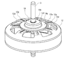
図3に示すように、回転子ヨーク12は、天面部12aの中央の回転子ハブ12bには筒状のボス部12cが起立形成されている。このボス部12cには、回転子軸3が圧入、焼嵌め、接着等によって一体に組み付けられる。また、天面部12aには、周方向で等間隔に複数の抜き孔(貫通孔)12dが設けられている。これらの抜き孔12dは、回転子ヨーク12の重量を軽量化するために設けられている。
As shown in FIG. 3, in the
また、図4に示すように、回転子ハブ12bの内底部12b1には、円板状の補強ハブ14が回転子軸3と一体に組み付けられ、回転子ハブ12bと同心状に重ね合わせて組み付けられている。図5に示すように補強ハブ14は、SUS等の金属板が絞り加工されて形成された底部14bを囲む側部14cの外周縁部に形成されたフランジ部14gが回転子ハブ12bと重ね合わせて組み付けられている。
Further, as shown in FIG. 4, a disc-shaped reinforcing
補強ハブ14は、底部中央部にバーリング加工されて形成された筒状のボス部14aが起立形成されている。このボス部14aの筒孔に回転子軸3が圧入、焼嵌め、接着等によって一体に組み付けられる(図2参照)。
これにより、回転子ヨーク12と回転子軸3との嵌合部の強度を向上させて天面振れを抑制して、モータ固有の振動数と負荷となるインペラ2(被回転体)の回転により発生する振動数を異ならせて共振するのを防いで静音化を実現することができる。
The reinforcing
As a result, the strength of the fitting portion between the
図4に示すように、回転子ハブ12bの内底部12b1には、径方向に複数の放射状リブ12e(天面部12aを上視すると放射状溝12g:図3)と回転子軸10と同心円状の環状リブ12f(天面部12aを上視すると環状溝12h:図3)のうち少なくともいずれかが形成されていることが好ましい。本実施例は、放射状リブ12e(放射状溝12g:図3)が環状リブ12f(環状溝12h:図3)と交差するように形成されている。
As shown in FIG. 4, the inner bottom portion 12b1 of the
補強ハブ14は、カップ状に形成された回転子ヨーク12の内底部側において回転子ハブ12bに形成された同心円状の環状リブ12fにフランジ部14g(外周縁部)を重ね合わせて組み付けられる。
The reinforcing
これにより、回転子ハブ12b自体の機械的強度が向上するうえに回転子ハブ12bに重ね合わせた補強ハブ14により更に回転子ヨーク12の強度が向上するため、回転子ヨーク12が振動し難くなるため、静音化を向上することができる。
特に、車載エアコン用モータの場合、モータ固有の振動数とエアコンユニットの共振による騒音が発生するおそれがあるが、上記回転子ヨーク12の回転子ハブ12bの内底部12b1設けたリブによって天面振れを防ぐとともに、回転子ハブ12bに補強ハブ14を重ね合わせて共振しない振動数に変化させることで静音化を図ることができる。
As a result, the mechanical strength of the
In particular, in the case of a motor for an in-vehicle air conditioner, noise may be generated due to the resonance of the motor's own frequency and the air conditioner unit. In addition to preventing the above, noise can be reduced by superimposing the reinforcing
[第二実施例]
次にアウターローラ型モータを備えた送風機の他例について図6乃至図10を参照して説明する。第一実施例と同一部材には同一番号を付して説明を援用するものとする。
[Second Example]
Next, another example of the blower provided with the outer roller type motor will be described with reference to FIGS. 6 to 10. The same members as in the first embodiment shall be assigned the same number and the description shall be incorporated.
本実施例は、インペラ2やモータ5の構造は第一実施例と同様であるが、回転子軸3に回転子ヨーク12とともに組み付けられる補強ハブ14の構成及び組み付け位置が異なっている。
図9に示すように、回転子ハブ12bの内底部12b1には、径方向に複数の放射状リブ12e(天面部12aを上視すると放射状溝12g:図8)と回転子軸10と同心円状の環状リブ12f(天面部12aを上視すると環状溝12h:図7)が形成されているのは第一実施例と同様である。
In this embodiment, the structures of the
As shown in FIG. 9, the inner bottom portion 12b1 of the
図6及び図7に示すように、補強ハブ14は、回転子ヨーク12の天面12a側において回転子ハブ12bに形成された環状溝12hに外周縁部であるフランジ部14gを重ね合わせて設けられる。
As shown in FIGS. 6 and 7, the reinforcing
即ち、図10に示すように、補強ハブ14は、SUS等の金属板が絞り加工されて形成された内底部14eを囲む側部14fの外周縁部に形成されたフランジ部14gが回転子ハブ12bと重ね合わせて組み付けられている。
補強ハブ14は、内底部14bの中央部に中心孔14dが穿孔されている。この中心孔14dに回転子軸3が圧入、焼嵌め、接着等によって一体に組み付けられる(図7参照)。
That is, as shown in FIG. 10, in the reinforcing
The reinforcing
具体的には、図7及び図8に示すように、補強ハブ14は、カップ状に形成された回転子ヨーク12の天面12a側において回転子ハブ12bに形成された同心円状の環状溝12hにフランジ部14g(外周縁部)を重ね合わせて組み付けられる。
Specifically, as shown in FIGS. 7 and 8, the reinforcing
図6に示すように、補強ハブ14は、回転子ヨーク12の天面12aに重ね合わせて組み付けられたまま、インペラ2の収納空間4に収納されて回転子軸3に一体に組み付けられる。
As shown in FIG. 6, the reinforcing
上記構成によっても、回転子ハブ12b自体の機械的強度が向上するうえに回転子ハブ12bに重ね合わせた補強ハブ14により更に回転子ヨーク12の強度が向上するため、回転子ヨーク12が天面振れし難くなり、静音化することができる。
Even with the above configuration, the mechanical strength of the
尚、回転子ヨーク12の回転子ハブ12bに形成される放射状リブ12eと 環状リブ12fは、内底部12b1側に凸となるように形成されることがより好ましいが、天面部12a側に凸となるように形成されていてもよい。
また、放射状リブ12eと環状リブ12fの数は、実施例に開示された形態に限られるものではなく、更に多くても少なくてもよい。
また、補強ハブ14の形態は、円板状に限らず、花形や爪形状等他の形態であってもよい。
更には、補強ハブ14回転子ヨーク12の内底部12b1に重ねて配置する場合には、天面部12aに重ねて配置する場合に比べて、騒音の発生を抑えられ回転子の軸方向の高さが抑えられるため、好ましい。
The
Further, the number of the
Further, the shape of the reinforcing
Further, when the reinforcing
1 送風機 2 インペラ 3 回転子軸 4 収納空間 5 モータ 5A 固定子 5B 回転子 6 モータベース部 7 モータ基板 8 軸受ハウジング 9a,9b 軸受部 10 固定子コア 10a 固定子極歯 10b コアバック部 10c モータコイル 11 インシュレータ 12 回転子ヨーク 12a 天面部 12b 回転子ハブ 12b1 内底部 12c ボス部 12d 抜き孔 12e 放射状リブ 12f 環状リブ 12g 放射状溝 12h 環状溝 13 回転子磁石 14 補強ハブ 14a ボス部 14b 底部 14c,14f 側部 14d 中心孔 14e 内底部 14g フランジ部
1
Claims (5)
前記回転子ヨークは、カップ状に形成された天面部に回転子ハブが回転子軸と一体に組み付けられ、
前記回転子ハブの内底部には、少なくとも前記回転子軸と同心状の環状リブが形成されており、
前記回転子ヨークの内底部において前記回転子ハブに形成された環状リブにフランジ部を重ね合わせて補強ハブが前記回転子ヨークと共に前記回転子軸に同心状に組み付けられていることを特徴とするアウターロータ型モータ。 A stator having a stator core with a coil wound around the stator pole teeth and a rotor shaft integrally assembled to the center of a rotor yoke having a rotor magnet facing the stator pole teeth rotate. An outer rotor type motor equipped with a rotor that is pivotally supported.
In the rotor yoke, the rotor hub is integrally assembled with the rotor shaft on the top surface formed in a cup shape.
An annular rib at least concentric with the rotor shaft is formed on the inner bottom portion of the rotor hub.
A flange portion is superposed on an annular rib formed on the rotor hub at the inner bottom portion of the rotor yoke, and a reinforcing hub is concentrically assembled to the rotor shaft together with the rotor yoke. Outer rotor type motor.
前記回転子ヨークは、カップ状に形成された天面部に回転子ハブが回転子軸と一体に組み付けられ、In the rotor yoke, the rotor hub is integrally assembled with the rotor shaft on the top surface formed in a cup shape.
前記回転子ハブの天面部には、少なくとも前記回転子軸と同心状の環状溝が形成されており、An annular groove concentric with the rotor shaft is formed on the top surface of the rotor hub.
前記回転子ヨークの天面部において前記回転子ハブに形成された環状溝にフランジ部を重ね合わせて補強ハブが前記回転子ヨークと共に前記回転子軸に同心状に組み付けられていることを特徴とするアウターロータ型モータ。A reinforcing hub is concentrically assembled to the rotor shaft together with the rotor yoke by superimposing a flange portion on an annular groove formed in the rotor hub on the top surface portion of the rotor yoke. Outer rotor type motor.
Priority Applications (4)
| Application Number | Priority Date | Filing Date | Title |
|---|---|---|---|
| JP2017014501A JP6827331B2 (en) | 2017-01-30 | 2017-01-30 | Outer rotor type motor |
| EP17210621.3A EP3355451A1 (en) | 2017-01-30 | 2017-12-27 | Outer rotor type motor |
| US15/862,718 US10594186B2 (en) | 2017-01-30 | 2018-01-05 | Outer rotor type motor |
| CN201810068474.8A CN108377046A (en) | 2017-01-30 | 2018-01-24 | Outer rotor type motor |
Applications Claiming Priority (1)
| Application Number | Priority Date | Filing Date | Title |
|---|---|---|---|
| JP2017014501A JP6827331B2 (en) | 2017-01-30 | 2017-01-30 | Outer rotor type motor |
Publications (2)
| Publication Number | Publication Date |
|---|---|
| JP2018125920A JP2018125920A (en) | 2018-08-09 |
| JP6827331B2 true JP6827331B2 (en) | 2021-02-10 |
Family
ID=60813663
Family Applications (1)
| Application Number | Title | Priority Date | Filing Date |
|---|---|---|---|
| JP2017014501A Expired - Fee Related JP6827331B2 (en) | 2017-01-30 | 2017-01-30 | Outer rotor type motor |
Country Status (4)
| Country | Link |
|---|---|
| US (1) | US10594186B2 (en) |
| EP (1) | EP3355451A1 (en) |
| JP (1) | JP6827331B2 (en) |
| CN (1) | CN108377046A (en) |
Families Citing this family (16)
| Publication number | Priority date | Publication date | Assignee | Title |
|---|---|---|---|---|
| JP6856446B2 (en) * | 2017-05-23 | 2021-04-07 | 澤藤電機株式会社 | Rotor structure in outer rotor type motor |
| FR3069586B1 (en) * | 2017-07-26 | 2021-01-01 | Valeo Systemes Thermiques | AIR PULSER FOR AUTOMOTIVE VEHICLES |
| US10910910B2 (en) * | 2018-08-17 | 2021-02-02 | Whirlpool Corporation | Acoustical treatment for a rotor of a laundry appliance |
| WO2020170736A1 (en) * | 2019-02-22 | 2020-08-27 | 日本電産株式会社 | Motor and blower device |
| KR102258295B1 (en) * | 2019-11-14 | 2021-06-01 | 주식회사 삼현 | Generator for hybrid drone |
| TWI725683B (en) * | 2019-12-24 | 2021-04-21 | 建準電機工業股份有限公司 | Impeller and cooling fan including the same |
| FR3111024A1 (en) * | 2020-06-01 | 2021-12-03 | Valeo Systemes Thermiques | Motor rotor, in particular for motor vehicle heating, ventilation and / or air conditioning system fan motor |
| DE102020215183A1 (en) * | 2020-12-02 | 2022-06-02 | BSH Hausgeräte GmbH | Rotor with integrated fan, electric motor, pump device, household appliance and manufacturing method |
| KR102286878B1 (en) * | 2021-02-10 | 2021-08-09 | 이만홍 | EC motor with driver control function improved |
| US11909268B2 (en) | 2021-03-11 | 2024-02-20 | ZF Active Safety US Inc. | Integrated rotor |
| DE102021204575A1 (en) * | 2021-05-06 | 2022-11-10 | Zf Friedrichshafen Ag | Rotor arrangement for an electrical machine |
| GB2608165B (en) * | 2021-06-24 | 2024-04-24 | Eta Green Power Ltd | Rotor for an electric machine |
| BR102022012579A2 (en) * | 2021-06-24 | 2022-12-27 | Eta Green Power Limited | ROTOR FOR AN ELECTRIC MACHINE |
| GB2608167B (en) * | 2021-06-24 | 2023-11-22 | Eta Green Power Ltd | Rotor for an electric machine |
| KR102587281B1 (en) * | 2021-07-07 | 2023-10-10 | 김태헌 | Rotor for outer rotary type bldc motor and bldc motor with the same |
| US20250070619A1 (en) * | 2023-08-22 | 2025-02-27 | Milwaukee Electric Tool Corporation | Power tool including a motor with blower fan blades |
Family Cites Families (20)
| Publication number | Priority date | Publication date | Assignee | Title |
|---|---|---|---|---|
| US3691542A (en) * | 1970-11-02 | 1972-09-12 | Diablo Systems Inc | Magnetic memory disk drive apparatus with reduced r. f. noise |
| US4318017A (en) | 1980-01-04 | 1982-03-02 | Timex Corporation | Rotor assembly for electric stepping motor |
| JP2500696B2 (en) * | 1990-02-02 | 1996-05-29 | ダイキン工業株式会社 | Fan device |
| JPH06189488A (en) * | 1992-12-16 | 1994-07-08 | Toshiba Corp | Bracket for rotating electric machine |
| JPH07332291A (en) * | 1994-06-10 | 1995-12-22 | Hitachi Ltd | Fan mounting structure for air conditioners |
| EP1018795B1 (en) * | 1999-01-08 | 2008-03-05 | Lg Electronics Inc. | Structure of rotor for outer rotor type brushless motor |
| JP2002315245A (en) * | 2001-04-09 | 2002-10-25 | Moric Co Ltd | Permanent magnet generator rotor |
| JP4325289B2 (en) * | 2003-06-12 | 2009-09-02 | 国産電機株式会社 | Magnet generator rotor |
| WO2005121575A1 (en) | 2004-06-11 | 2005-12-22 | Seiko Instruments Inc. | Fluid dynamic pressure bearing, motor, and recording medium drive device |
| JP2006058640A (en) * | 2004-08-20 | 2006-03-02 | Victor Co Of Japan Ltd | Polygon mirror driving motor |
| US8621896B2 (en) * | 2005-11-30 | 2014-01-07 | Lg Electronics Inc. | Washing machine |
| TW200925802A (en) * | 2007-12-04 | 2009-06-16 | Sunonwealth Electr Mach Ind Co | Revolving polygon mirror counterweight structure of color laser printer |
| DE102008008965A1 (en) | 2008-02-13 | 2009-08-20 | Continental Automotive Gmbh | electric motor |
| CN103081303B (en) * | 2010-06-25 | 2016-01-27 | 菲舍尔和佩克尔应用有限公司 | Motor rotor, motor, electrical appliance including the rotor, and manufacturing method of the rotor |
| ITTO20111159A1 (en) * | 2011-12-15 | 2013-06-16 | Gate Srl | ELECTRIC MOTOR FOR THE OPERATION OF A IMPELLER OF A FAN FOR A HEAT EXCHANGER OF A MOTOR VEHICLE. |
| WO2013184961A1 (en) * | 2012-06-06 | 2013-12-12 | Nidec Motor Corporation | Motor having spoked outer rotor with spaced apart pole segments |
| JP6183995B2 (en) | 2013-06-17 | 2017-08-23 | ミネベアミツミ株式会社 | Blower fan |
| CN204118974U (en) * | 2014-10-11 | 2015-01-21 | 上海电科电机科技有限公司 | Installation Structure of Standard Shaft Type Incremental Encoder for Variable Frequency Motor |
| JP6133259B2 (en) * | 2014-10-27 | 2017-05-24 | ミネベアミツミ株式会社 | Spindle motor |
| JP6719057B2 (en) * | 2015-06-08 | 2020-07-08 | パナソニックIpマネジメント株式会社 | Brushless DC motor, blower |
-
2017
- 2017-01-30 JP JP2017014501A patent/JP6827331B2/en not_active Expired - Fee Related
- 2017-12-27 EP EP17210621.3A patent/EP3355451A1/en not_active Withdrawn
-
2018
- 2018-01-05 US US15/862,718 patent/US10594186B2/en active Active
- 2018-01-24 CN CN201810068474.8A patent/CN108377046A/en active Pending
Also Published As
| Publication number | Publication date |
|---|---|
| JP2018125920A (en) | 2018-08-09 |
| US20180219446A1 (en) | 2018-08-02 |
| CN108377046A (en) | 2018-08-07 |
| EP3355451A1 (en) | 2018-08-01 |
| US10594186B2 (en) | 2020-03-17 |
Similar Documents
| Publication | Publication Date | Title |
|---|---|---|
| JP6827331B2 (en) | Outer rotor type motor | |
| US6483209B1 (en) | Balance rings for motors | |
| JP7080621B2 (en) | Outer rotor motor and vacuum cleaner equipped with it | |
| JP6447662B2 (en) | Electric motor system and turbo compressor provided with the same | |
| JP2014113030A (en) | Motor | |
| JP2012097655A (en) | Blower fan | |
| JP3809438B2 (en) | Centrifugal blower | |
| US20120003109A1 (en) | Blower fan | |
| JP2005133710A (en) | Centrifugal blower and air conditioner using the same | |
| JP2002206499A (en) | Impeller for axial blower | |
| JP2014015908A (en) | Blower unit | |
| JP4532964B2 (en) | Double rotor motor | |
| JP2023145035A (en) | motor | |
| JP2007100600A (en) | Air blowing fan and air blower | |
| JP2006087190A (en) | Motor with non-cylindrical gap | |
| JP5581623B2 (en) | Motor, manufacturing method thereof and blower fan | |
| JP5708932B2 (en) | Brushless motor, outer rotor type brushless motor and blower | |
| JP5393291B2 (en) | Motor equipment | |
| JP6299503B2 (en) | Rotating electric machine | |
| JP2020029772A (en) | Centrifugal blower | |
| JP2020105973A (en) | Axial flow fan | |
| JP2019203481A (en) | Centrifugal fan | |
| JP5846784B2 (en) | Brushless vibration motor | |
| WO2025009282A1 (en) | Axial gap motor, blower device, and air conditioner | |
| JP2023177657A (en) | brushless motor |
Legal Events
| Date | Code | Title | Description |
|---|---|---|---|
| A621 | Written request for application examination |
Free format text: JAPANESE INTERMEDIATE CODE: A621 Effective date: 20190904 |
|
| A131 | Notification of reasons for refusal |
Free format text: JAPANESE INTERMEDIATE CODE: A131 Effective date: 20201110 |
|
| A521 | Request for written amendment filed |
Free format text: JAPANESE INTERMEDIATE CODE: A523 Effective date: 20201214 |
|
| TRDD | Decision of grant or rejection written | ||
| A01 | Written decision to grant a patent or to grant a registration (utility model) |
Free format text: JAPANESE INTERMEDIATE CODE: A01 Effective date: 20210112 |
|
| A61 | First payment of annual fees (during grant procedure) |
Free format text: JAPANESE INTERMEDIATE CODE: A61 Effective date: 20210119 |
|
| R150 | Certificate of patent or registration of utility model |
Ref document number: 6827331 Country of ref document: JP Free format text: JAPANESE INTERMEDIATE CODE: R150 |
|
| R250 | Receipt of annual fees |
Free format text: JAPANESE INTERMEDIATE CODE: R250 |
|
| LAPS | Cancellation because of no payment of annual fees |