JP6826773B2 - Electrical connector device for cable - Google Patents
Electrical connector device for cable Download PDFInfo
- Publication number
- JP6826773B2 JP6826773B2 JP2016181432A JP2016181432A JP6826773B2 JP 6826773 B2 JP6826773 B2 JP 6826773B2 JP 2016181432 A JP2016181432 A JP 2016181432A JP 2016181432 A JP2016181432 A JP 2016181432A JP 6826773 B2 JP6826773 B2 JP 6826773B2
- Authority
- JP
- Japan
- Prior art keywords
- plug
- lycee
- pair
- shell
- members
- Prior art date
- Legal status (The legal status is an assumption and is not a legal conclusion. Google has not performed a legal analysis and makes no representation as to the accuracy of the status listed.)
- Active
Links
- 230000000903 blocking effect Effects 0.000 claims description 29
- 239000004020 conductor Substances 0.000 claims description 27
- 230000008054 signal transmission Effects 0.000 claims description 23
- 239000002184 metal Substances 0.000 claims description 9
- 230000013011 mating Effects 0.000 claims 2
- 230000002093 peripheral effect Effects 0.000 description 56
- 230000005540 biological transmission Effects 0.000 description 9
- 239000000758 substrate Substances 0.000 description 7
- 238000005476 soldering Methods 0.000 description 3
- 230000000694 effects Effects 0.000 description 1
- 230000005611 electricity Effects 0.000 description 1
- 238000009413 insulation Methods 0.000 description 1
- 239000000463 material Substances 0.000 description 1
- 238000000465 moulding Methods 0.000 description 1
- 230000005405 multipole Effects 0.000 description 1
- 230000000149 penetrating effect Effects 0.000 description 1
- 229910000679 solder Inorganic materials 0.000 description 1
- 239000000126 substance Substances 0.000 description 1
- 238000003466 welding Methods 0.000 description 1
Images


Description
本発明は、ケーブル状の信号伝送部材(以後、「ケーブル状信号伝送部材」と称す)が連結されたプラグコネクタを、配線基板に実装されたリセプタクルコネクタに嵌合させる構成を備えたケーブル用電気コネクタ装置に関する。 The present invention provides cable electricity having a configuration in which a plug connector to which a cable-shaped signal transmission member (hereinafter referred to as "cable-shaped signal transmission member") is connected is fitted to a receptacle connector mounted on a wiring board. Regarding connector devices.
一般に、種々の電気機器において信号の伝送を行うにあたって、細線同軸ケーブル等のケーブル状信号伝送部材をプラグコネクタに連結するとともに、配線基板の主面上にリセプタクルコネクタを実装し、そのリセプタクルコネクタに対してプラグコネクタを嵌合させることで電気的な接続を行うようにしたケーブル用電気コネクタ装置が広く採用されている。このような電気コネクタ装置では、両コネクタ同士の嵌合時に、双方のコンタクト部材の接点部が接触状態となって信号の伝送が行われる。 Generally, when transmitting signals in various electric devices, a cable-shaped signal transmission member such as a thin coaxial cable is connected to a plug connector, and a receptacle connector is mounted on the main surface of a wiring board, and the receptacle connector is used. An electric connector device for a cable is widely adopted in which an electrical connection is made by fitting a plug connector. In such an electric connector device, when both connectors are fitted to each other, the contact portions of both contact members are in a contact state and a signal is transmitted.
一方、上述したように両コネクタが嵌合された際に、伝送信号の電磁遮蔽が行われるようにした構成が従来からしばしば採用されている。すなわち、その電磁遮蔽構造は、両コネクタに設けられた導電性シェル同士が、嵌合時に複数箇所で互いに接触状態になされ、それらの導電性シェルの接触部分が、コンタクト部材を含む信号伝送経路を覆うことによって、信号伝送経路から放射される電磁波の外部伝搬を抑制するようにしたものである。 On the other hand, as described above, a configuration in which the transmission signal is electromagnetically shielded when both connectors are fitted is often adopted. That is, in the electromagnetic wave shielding structure, the conductive shells provided in both connectors are brought into contact with each other at a plurality of places at the time of fitting, and the contact portions of the conductive shells provide a signal transmission path including a contact member. By covering it, the external propagation of electromagnetic waves radiated from the signal transmission path is suppressed.
しかしながら、従来のケーブル用電気コネクタ装置に設けられた電磁遮蔽構造においては、例えばリセコンタクトの先端部分が、枠状体をなす導電性のリセシェルの外方に突出しており、電気コネクタ装置の外方にリセコンタクトの一部が露出した状態になされている。このような構成では、ケーブル用電気コネクタ装置として十分な電磁遮蔽作用が得られないことが考えられる。また、伝送信号の高周波化が顕著に進められている近年では、高周波信号に対する電磁遮蔽特性(EMI特性)を更に向上させることが要請されている。 However, in the electromagnetic shielding structure provided in the conventional electric connector device for cables, for example, the tip portion of the lycee contact protrudes to the outside of the conductive lycee shell forming a frame shape, and is outside the electric connector device. A part of the lycee contact is exposed. With such a configuration, it is conceivable that a sufficient electromagnetic shielding action cannot be obtained as an electric connector device for a cable. Further, in recent years, when the frequency of transmission signals has been remarkably increased, it is required to further improve the electromagnetic shielding characteristics (EMI characteristics) for high frequency signals.
そこで本発明は、簡易な構成で、伝送信号に関する電磁遮蔽を嵌合状態において容易かつ十分に行わせることができるようにしたケーブル用電気コネクタ装置を提供することを目的とする。 Therefore, an object of the present invention is to provide an electric connector device for a cable, which has a simple configuration and can easily and sufficiently perform electromagnetic shielding related to a transmission signal in a fitted state.
上記目的を達成するため請求項1にかかる発明では、中心導体及び外部導体を有する複数のケーブル状信号伝送部材が連結されるプラグコネクタが、配線基板の主面に実装されるリセプタクルコネクタに嵌合される構成を備えたものであって、前記プラグコネクタは、前記各ケーブル状信号伝送部材の中心導体に接続されて前記ケーブル状信号伝送部材の延在方向に延在する導電性のプラグコンタクトと、そのプラグコンタクトが複数体にわたって配列された絶縁性のプラグハウジングと、前記プラグハウジングに装着されて前記複数のケーブル状信号伝送部材の外部導体に接続される導電性のプラグシェルと、を備えているとともに、前記リセプタクルコネクタは、前記プラグコネクタが嵌合された状態で、前記プラグコンタクトのそれぞれに接続される導電性の複数のリセコンタクトと、それら複数のリセコンタクトが配列される絶縁性のリセハウジングと、前記リセハウジングに配置され、前記プラグコネクタが嵌合された際に、前記プラグシェルに対して挟持する状態で接触する導電性のリセシェルと、を備えたケーブル用電気コネクタ装置において、前記プラグシェルは、前記延在方向において予め定められた距離を隔てて設けられた一対のプラグ側遮蔽部材を有し、それら一対のプラグ側遮蔽部材の間部分に前記プラグコンタクトのそれぞれが配置されているとともに、前記リセシェルは、前記延在方向に予め定められた距離を隔てて設けられた一対のリセ側遮断部材を有し、それら一対のリセ側遮蔽部材の間部分に前記リセコンタクトのそれぞれが配置され、前記プラグコネクタとリセプタクルコネクタとが嵌合された状態において、前記一対のプラグ側遮蔽部材のうちの一方と前記一対のリセ側遮蔽部材のうちの一方とが対向配置されて、一組の二重遮蔽壁部が構成されているとともに、前記一対のプラグ側遮蔽部材のうちの他方と前記一対のリセ側遮蔽部材のうちの他方とが対向配置されて、他の一組の二重遮蔽壁部が構成され、前記一組の二重遮蔽壁部と、前記他の一組の二重遮蔽壁部とは、前記延在方向に予め定められた距離を隔てて一対をなす状態に配置され、当該一対をなす二重遮蔽壁部同士の間部分に、前記プラグコンタクト及びリセコンタクトが配置されるものであって、前記リセシェルは、前記一対のリセ側遮断部材を前記延在方向に掛け渡す一対のリセ側遮断接続部材を備え、それら一対のリセ側遮断部材及び一対のリセ側遮断接続部材により前記リセシェルが枠状体から構成され、前記リセシェルを構成する前記枠状体は、前記複数のリセコンタクトを前記嵌合の方向に略同一の高さで囲んだ状態に延在しているとともに、前記プラグシェルは、前記一対のプラグ側遮断部材を前記延在方向に掛け渡す一対のプラグ側遮断接続部材を備え、それら一対のプラグ側遮断部材及び一対のプラグ側遮断接続部材により前記プラグシェルが枠状体から構成され、前記プラグシェルを構成する前記枠状体は、前記複数のプラグコンタクトを前記嵌合の方向に略同一の高さで囲んだ状態に延在する構成が採用されている。
In the invention according to
このような構成を備えた本発明によれば、リセプタクルコネクタに対してプラグコネクタが嵌合された際に、プラグシェルの一部とリセシェルの一部とからなる一対の二重遮蔽壁部同士の間部分に、プラグコンタクト及びリセコンタクトが配置されることから、伝送信号に対して良好な電磁遮蔽作用が得られ、高周波伝送においても十分なEMI対策が可能となる。
特に、リセ側遮断部材とリセ側遮断接続部材とにより形成された枠状体によって、プラグコンタクト及びリセコンタクトが外方から略同一の高さで取り囲まれた状態になされることから、電磁遮蔽作用がさらに高められるとともに、プラグ側遮断部材とプラグ側遮断接続部材とにより形成された枠状体によって、プラグコンタクト及びリセコンタクトが外方から取り囲まれた状態になされることから、電磁遮蔽作用がさらに高められることとなる。
According to the present invention having such a configuration, when the plug connector is fitted to the receptacle connector, a pair of double-shielding wall portions including a part of the plug shell and a part of the recess shell are connected to each other. Since the plug contact and the lycee contact are arranged in the intermediate portion, a good electromagnetic shielding action can be obtained for the transmission signal, and sufficient EMI countermeasures can be taken even in high frequency transmission.
In particular, since the plug contact and the lycee contact are surrounded by the frame-shaped body formed by the lycee side blocking member and the lycee side blocking connecting member at substantially the same height from the outside, the electromagnetic shielding action Is further enhanced, and the plug contact and the lycee contact are surrounded from the outside by the frame-shaped body formed by the plug-side blocking member and the plug-side blocking connection member, so that the electromagnetic shielding action is further enhanced. It will be enhanced.
さらに、本発明においては、前記リセコンタクトが、前記プラグコンタクトとの接触部分から前記延在方向に延出する自由端部を有する一方、前記リセハウジングは、前記一対のリセ側遮断部材及び一対のリセ側遮断接続部材に囲まれた状態に配置されているとともに、前記リセハウジングに、前記リセハウジングを前記配線基板の主面と直交する方向に貫通した窓が設けられたものであって、前記窓の開口部が、前記リセコンタクトの自由端部に対面した状態に配置されていることが望ましい。
Further, in the present invention, the Lise contact, while having a free end portion extending in the extending direction from the contact portion between the plug contacts, said Lise housing, the pair Lise-side blocking member and the pair It is arranged in a state of being surrounded by a lycee side blocking connection member, and the lycee housing is provided with a window penetrating the lycee housing in a direction orthogonal to the main surface of the wiring board. It is desirable that the opening of the window is arranged so as to face the free end of the lycee contact.
このような構成を備えた本発明によれば、リセハウジングに設けられた窓を通して、プラグシェルとリセシェルとからなる二重遮蔽壁部同士の間部分に配置されたプラグコンタクト及びリセコンタクトの配線基板に対する接続状態が容易かつ確実に確認される。 According to the present invention having such a configuration, a plug contact and a lycee contact wiring board arranged in a portion between the double-shielding wall portions including the plug shell and the lycee shell through a window provided in the lycee housing. The connection status to is easily and surely confirmed.
また、本発明における前記プラグシェル及びリセシェルは、少なくとも嵌合時に接触する部分が、金属部材から構成されていることが望ましい。 Further, it is desirable that the plug shell and the lycee shell in the present invention have at least a portion that comes into contact with each other when fitted, which is made of a metal member.
このような構成を備えた本発明によれば、リセプタクルコネクタに対するプラグコネクタの嵌合操作が、プラグシェルとリセシェルとの金属部材同士の接触によって容易かつ安定的に行われる。 According to the present invention having such a configuration, the fitting operation of the plug connector with respect to the receptacle connector is easily and stably performed by the contact between the metal members of the plug shell and the recess shell.
以上述べたように本発明にかかるケーブル用電気コネクタ装置は、ケーブル状信号伝送部材の内部導体及び外部導体に接続されるプラグシェル及びリセシェルに、ケーブル状信号伝送部材の延在方向において予め定められた距離を隔てて一対のプラグ側遮蔽部材及びリセ側遮断部材を設け、プラグコネクタとリセプタクルコネクタとが嵌合された状態において、一対のプラグ側遮蔽部材及びリセ側遮蔽部材の組からなる一対の二重遮蔽壁部をケーブル状信号伝送部材の延在方向に予め定められた距離を隔てて対向配置し、それら一対の二重遮蔽壁部同士の間部分にプラグコンタクト及びリセコンタクトを配置する一方、リセシェル及びプラグシェルの双方を、リセコンタクト及びプラグコンタクトを略同一の高さで囲む枠状体としたことで、伝送信号に対して良好な電磁遮蔽作用を得るように構成したものであるから、簡易な構成で、伝送信号に関する電磁遮蔽を嵌合状態において容易かつ十分に行わせることができる。
As described above, the electric connector device for a cable according to the present invention is predetermined in the extending direction of the cable-shaped signal transmission member on the plug shell and the recess shell connected to the inner conductor and the outer conductor of the cable-shaped signal transmission member. A pair of plug-side shielding members and a lycee-side blocking member are provided at a distance from each other, and a pair of a pair of plug-side shielding members and a lycee-side shielding member are provided in a state where the plug connector and the receptacle connector are fitted. opposed spaced a predetermined distance double shielding wall portion in the extending direction of the cable-like signal transmission member, while arranging the plug contacts and Lise contact their pair of double-shielding wall portion between the portion between the , Both the lycee shell and the plug shell are frame-shaped bodies that surround the lycee contact and the plug contact at substantially the same height , so that a good electromagnetic shielding action is obtained for the transmission signal. With a simple configuration, electromagnetic shielding of the transmission signal can be easily and sufficiently performed in the fitted state.
以下、ケーブル状信号伝送部材としての複数本の細線同軸ケーブルを用いたケーブル用電気コネクタ装置に本発明を適用した場合の実施形態に関する説明を図面に基づいて詳細に行う。 Hereinafter, an embodiment in the case where the present invention is applied to an electric connector device for a cable using a plurality of thin coaxial cables as a cable-shaped signal transmission member will be described in detail with reference to the drawings.
[ケーブル用電気コネクタ装置の全体構造について]
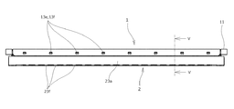
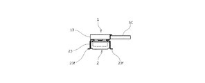
まず、図1〜図5に示された本発明の一実施形態にかかるケーブル用電気コネクタ装置は、細線同軸ケーブル(ケーブル状信号伝送部材)SCの端末部分が連結されたプラグコネクタ1と、印刷配線基板(図示省略)の主面に実装されたリセプタクルコネクタ2と、からなる垂直嵌合型コネクタ装置を構成するものであって、リセプタクルコネクタ2の直上に配置されたプラグコネクタ1が、図示を省略した印刷配線基板の主面と略直交する図3〜図5の下方側に向かって下降されることによって、前記リセプタクルコネクタ2に設けられた凹み状の嵌合凹部にプラグコネクタ1に設けられた凸状の嵌合凸部が差し込まれるようにして両コネクタ1,2同士の嵌合が行われるようになっている。
[Overall structure of electrical connector device for cables]
First, the cable electric connector device according to the embodiment of the present invention shown in FIGS. 1 to 5 is printed with a
なお、以下においては、印刷配線基板の主面が「水平方向」に延在しているものとする。また、その印刷配線基板の主面と直交する方向を「上下方向」とし、プラグコネクタ1を差し込む方向を「下方向」、それとは反対の抜き出す方向を「上方向」とする。
In the following, it is assumed that the main surface of the printed wiring board extends in the "horizontal direction". Further, the direction orthogonal to the main surface of the printed wiring board is defined as "vertical direction", the direction in which the
上述したプラグコネクタ1及びリセプタクルコネクタ2は、平面視において細長状の略長方形状になされており、一対の長手側端縁部と一対の短手側端縁部とを有している。そして、プラグコネクタ1が有している一対の長手側端縁部のうちの一方側の端縁部(図2の上側端縁部)に、多極状に並列するように配列された複数本の細線同軸ケーブルSCの端末部分が連結されている。
The
以下においては、細線同軸ケーブルSCの端末部分が延在している方向を「前後方向」とし、当該細線同軸ケーブルSCの端末部分が連結される側の長手側端縁部を「後端縁部」、それに対向している反対側の他方の長手側端縁部を「前端縁部」と呼ぶこととする。さらに、それらプラグコネクタ1の「後端縁部」及び「前端縁部」に対応するリセプタクルコネクタ2の各端縁部についても、同様に「後端縁部」及び「前端縁部」と呼ぶこととし、また、それらの「後端縁部」及び「前端縁部」に各々向かう方向を「後方向」及び「前方向」とする。さらに、プラグコネクタ1及びリセプタクルコネクタ2の長手方向を、単に「長手方向」又は「多極配列方向」と呼ぶ。
In the following, the direction in which the terminal portion of the thin coaxial cable SC extends is defined as the "front-back direction", and the longitudinal end edge portion on the side where the terminal portion of the thin coaxial cable SC is connected is referred to as the "rear end edge portion". , The other longitudinal end edge on the opposite side facing it is referred to as the "front end edge". Further, each end edge portion of the
[細線同軸ケーブルについて]
上述した細線同軸ケーブルSCのそれぞれにおける端末部分には、図6〜図10にも示されているように、被覆材が皮剥きされることによってケーブル中心導体(信号線)SCa及びケーブル外部導体(シールド線)SCbが同軸状をなすように露出されており、当該細線同軸ケーブルSCの中心軸線に沿うようにして配置されたケーブル中心導体SCaが、プラグコネクタ1に設けられた後述の各プラグコンタクト12のそれぞれに半田付けされる。このプラグコネクタ1の各プラグコンタクト12は、リセプタクルコネクタ2に設けられた後述のリセコンタクト22に接触し、それにより信号回路が構成されるようになっている。
[About thin coaxial cable]
As shown in FIGS. 6 to 10, the terminal portion of each of the above-mentioned thin coaxial cable SCs has a cable center conductor (signal line) SCa and a cable outer conductor (signal line) SCa by peeling the covering material. The shielded wire) SCb is exposed so as to form a coaxial shape, and the cable center conductor SCa arranged along the central axis of the thin coaxial cable SC is provided with each plug contact described later in the
また、細線同軸ケーブルSCのケーブル外部導体SCbは、上記ケーブル中心導体SCaと絶縁された状態で外周側を取り囲むように配置されており、グランド部材を構成している上部グランドバーGUと下部グランドバーGDとの間において当該ケーブル外部導体SCbが上下に挟持される配置関係になされている。
それらの上部グランドバーGU及び下部グランドバーGDは、多極配列方向に沿って長尺状に延在する細長の帯板状部材から形成されており、半田付けやカシメや圧接等によりケーブル外部導体SCbに接続された状態で、後述するプラグコネクタ1のプラグシェル13に接触し、それにより接地用のグランド回路が構成されるようになっている。
Further, the cable outer conductor SCb of the thin coaxial cable SC is arranged so as to surround the outer peripheral side in a state of being insulated from the cable center conductor SCa, and the upper ground bar GU and the lower ground bar constituting the ground member are arranged. The cable outer conductor SCb is sandwiched up and down with the GD.
The upper ground bar GU and the lower ground bar GD are formed of elongated strip-shaped members extending in a long shape along the multi-pole arrangement direction, and are cable outer conductors by soldering, caulking, pressure welding, or the like. In the state of being connected to the SCb, it comes into contact with the
[絶縁ハウジング及びコンタクト部材について]
一方、上述したプラグコネクタ1及びリセプタクルコネクタ2は、細長板状をなす絶縁性部材からなるプラグハウジング11及びリセハウジング21をそれぞれ備えており、それらのプラグハウジング11及びリセハウジング21には、長手方向に沿って多数のプラグコンタクト12及びリセコンタクト22が適宜のピッチ間隔で多極状をなすように配列されている。これらの多数のプラグコンタクト12及びリセコンタクト22は、信号伝送用のシグナルコンタクトを構成しており、上述した細線同軸ケーブルSCのケーブル中心導体SCaの端末部分が半田付けされるようになっている。なお、これら複数のプラグコンタクト12及びリセコンタクト22のうちの一部を、接地用のグランドコンタクト(シールドコンタクト)とすることも可能である。
[Insulation housing and contact members]
On the other hand, the
上述した複数体のプラグコンタクト12及びリセコンタクト22は、それぞれ信号回路又はグランド回路を構成するものであるが、プラグハウジング11及びリセハウジング21に対しては、例えばインサート成形によって埋設された状態にて配置されている。このプラグコネクタ1に取り付けられた複数体のプラグコンタクト12は、略同一の形状をなすように形成されているとともに、リセプタクルコネクタ2に取り付けられたリセコンタクト22も、同様に略同一の形状をなすように形成されている。
The plurality of
より具体的に説明すると、特に図5及び図6に示されているように、プラグコネクタ1側に設けられたプラグコンタクト12は、略水平方向に延在する導体接続部12aを備えているとともに、その導体接続部12aの後端部(図5及び図6の右端部)から略直角下方(嵌合方向)に向かって折れ曲がって延出する嵌合接続部12bを有している。このうち導体接続部12aは、プラグハウジング11の「前後方向」における略中央部分に載置されており、上述した細線同軸ケーブルSCのケーブル中心導体SCaが上方側から当接されて、例えば半田付けにより接合される。このときの複数体のケーブル中心導体SCaとプラグコンタクト12の半田接合は一括的に行うことが可能である。
More specifically, as shown in FIGS. 5 and 6, the
一方、当該プラグコンタクト12の嵌合接続部12bにおいては、上下方向の途中位置に信号接点が設けられており、プラグコネクタ1がリセプタクルコネクタ2に嵌合されたときに、そのプラグコンタクト12の信号接点に対して、後述するリセプタクルコネクタ2のリセコンタクト22に設けられた信号接点凸部22cが接触状態となり、それらの両接点部の接触によって信号回路が構成されるようになっている。
On the other hand, in the
このようなプラグコネクタ1に設けられたプラグコンタクト12に対して、リセプタクルコネクタ2側のリセコンタクト22は、図12〜図17にも示されているように、側面視において略S状をなすように折り曲げ形成された弾性接続部22aを有しているとともに、その弾性接続部22aの前端部(図5及び図17の左端部)からは、略水平に延在する基板接続部22bが、ケーブル状信号伝送部材としての細線同軸ケーブルSCの延在方向である「前後方向」に延びている。この基板接続部22bは、リセコンタクト22における前方側(図5及び図17の左端側)において自由端部を構成するものであるが、その自由端部を構成している基板接続部22bは、印刷配線基板の主面上に設けられた信号導電路(図示省略)に対して半田付けで接合されることで電気的な接続が行われ、それによって信号回路が構成されるようになっている。
With respect to the
ここで、リセハウジング21には、特に図19及び図20に示されているように、上述したリセコンタクト22の自由端部を構成している基板接続部22bを目視可能とする窓21aが、各々のリセコンタクト22ごとに複数体にわたって形成されている。それら複数体の窓21aは、「長手方向(多極配列方向)」に並列された状態に配置されており、各窓21aが、印刷配線基板の主面と直交する「上下方向」に貫通する平面略矩形状の貫通穴から形成されている。そして、それらの各窓21aの開口部が、リセコンタクト22の自由端部である基板接続部22bに対して上方から臨むように配置されていることによって、当該窓21aを通して基板接続部22bの印刷配線基板に対する接続状態が、上方から目視で確認されるようになっている。
Here, in the
さらに、上述したリセコンタクト22の弾性接続部22aは、リセハウジング21における「前後方向」の略中央部分に配置されており、当該弾性接続部22aの後端側(図5及び図17の右端側)には、さらに後方側(図5及び図17の右方側)に向かって略「く」の字状に突出する信号接点凸部22cが設けられている。このリセコンタクト22に設けられた信号接点凸部22cは、プラグコネクタ1がリセプタクルコネクタ2に嵌合されたときに、前述したプラグコネクタ1側のプラグコンタクト12に設けられた信号接点部に対して、後方側(図5及び図17の右方側)に向かって略水平方向に弾性的に圧接された状態で接続され、それにより信号回路が構成されるようになっている。
Further, the
[プラグシェルについて]
一方、プラグコネクタ1の外方部分を構成するように装着された金属板状部材からなるプラグシェル13は、例えば図6に示すように、前述したプラグハウジング11の上面側部分を覆う上部プラグシェル13aと、プラグハウジング11の外周表面部分を覆う下部プラグシェル13bとから構成されている。このプラグコネクタ1のプラグシェル13は、グランド回路の一部を構成するものであって、下部プラグシェル13bが圧入により固定されたプラグハウジング11の上面に対して、前述した両グランドバー(グランド部材)GU,GDに半田接合された細線同軸ケーブルSCが載置され、さらにその細線同軸ケーブルSCの上方から上部プラグシェル13aが被せられるようにして装着される。このようなプラグシェル13が装着されることによって、プラグハウジング11の外表面のうち、リセプタクルコネクタ2が嵌合される部分を除くほぼ全体がプラグシェル13により覆われた状態になされる。
[About plug shell]
On the other hand, the
このとき、特に図11に示されているように、上述したプラグシェル13の上部プラグシェル13aには、「長手方向(多極配列方向)」の両端側部分に固定片13cが下方に突出するように折り曲げ形成されており、それらの固定片13cが、下部プラグシェル13bの長手方向における両側部分に設けられた係止部13dに対して弾性的に係合され、それによって上部プラグシェル13aと下部プラグシェル13bとが、長手方向の両端側部分で固定状態になされている。
At this time, as shown in FIG. 11, in particular, the
さらに、上述した下部プラグシェル13bの前端面部分には、前方側に突出するようにして複数体の固定片13eが設けられており、それらの各固定片13eが、上部プラグシェル13bの同じく前端面部分に複数体にわたって設けられた係止部13fに対して弾性的に係合され、それによって上部プラグシェル13aと下部プラグシェル13bとが、前端面部分において固定状態に維持されている。
Further, a plurality of fixing
このようにしてプラグコネクタ1に装着されたプラグシェル13の上部プラグシェル13a及び下部プラグシェル13bにおける各後端部分(図5の右端部分)には、特に図11に示されているように、後方側に向かって延出する複数体のグランド接続舌片13g,13hが、「長手方向(多極配列方向)」に所定の間隔なして設けられている。それらの各グランド接続舌片13g,13hは、片持ちの板バネ状をなすようにして略水平に延在しており、当該各グランド接続舌片13g,13hが、上述したようにプラグシェル13の装着が行われたときに、上部グランドバーGU及び下部グランドバーGDに対して上下の方向から挟むようにして圧接状態になされ(図5参照)、それによってグランド回路の一部が構成されるようになっている。
As shown in FIG. 11, the rear end portions (right end portions in FIG. 5) of the
ここで、前述したプラグシェル13の下部プラグシェル13bは、平面視において細長状の略長方形状になされており、同じく平面視において細長状の略長方形状になされたプラグハウジング11の外周表面部分を覆う枠状体から構成されている。すなわち、この下部プラグシェル13bは、プラグハウジング11の外周表面のうちの前端側(図5の左端側)及び後端側(図5の右端側)を覆う前部外周壁板13i及び後部外周壁板13jを有している。また、それらの前部外周壁板13i及び後部外周壁板13jの長手方向の両端部同士は、細線同軸ケーブルSCの延在方向である「前後方向」に延在する一対の側部外周壁板13k,13kにより掛け渡されており(図11参照)、これら前部外周壁板13i、後部外周壁板13j及び側部外周壁板13k,13kによって枠状体が形成されている。そして、このような枠状体からなるプラグシェル13の下部プラグシェル13bは、リセプタクルコネクタ2に設けられた嵌合凹部の内方側に挿入されるようにして嵌合されるようになっている。
Here, the
ここで、上述したプラグシェル13の下部プラグシェル13bにおける前後の金属壁部を構成している前部外周壁板13i及び後部外周壁板13jは、印刷配線基板の主面に実装されたリセプタクルコネクタ2にプラグコネクタ1が嵌合された際、印刷配線基板の主面から立ち上がるようにして上下方向に延在しており、これらの前部外周壁板13i及び後部外周壁板13jが、細線同軸ケーブルSCの延在方向である「前後方向」において予め定められた距離を隔てて配置されている。
Here, the front outer
[リセシェルについて]
これに対して、リセコネクタ2の外方部分を構成するように装着された金属板状部材からなるリセシェル23も、グランド回路の一部を構成するものであるが、特に図18に示されているように、リセハウジング21の外周表面部分を覆う平面略長方形状の細長状の枠状体から構成されている。すなわち、このリセシェル23は、リセハウジング21の外周表面のうちの前端側(図5の左端側)及び後端側(図5の右端側)を覆う前部外周壁板23a及び後部外周壁板23bを有しているとともに、それらの前部外周壁板23a及び後部外周壁板23bの長手方向の両端部同士を、細線同軸ケーブルSCの延在方向である「前後方向」に掛け渡す一対の側部外周壁板23c,23c(図12及び図18参照)を有している。
[About Riseshell]
On the other hand, the
このようなリセプタクルコネクタ2のリセシェル23における前後の壁部分を構成している前部外周壁板23a及び後部外周壁板23bは、印刷配線基板の主面にリセプタクルコネクタ2が実装された際、印刷配線基板の主面から立ち上がるようにして上下方向に延在しており、これらの前部外周壁板23a及び後部外周壁板23bが、細線同軸ケーブルSCの延在方向である「前後方向」において予め定められた距離を隔てて配置されている。
The front outer
このとき、上述した前部外周壁板23a及び後部外周壁板23bの下端縁部は、印刷配線基板の主面に沿って延在しているが、当該前部外周壁板23a及び後部外周壁板23bの下端縁部には、略水平に延出する複数体の基板接続部23f,23f,・・・が、長手方向に所定の距離を隔てて設けられている(図13参照)。これらの各基板接続部23fは、印刷配線基板の主面上に形成された接地用導電路(図示省略)に対して半田付けで接合され、それによってシールド回路が構成されるようになっている。
At this time, the lower end edges of the front outer
さらに、上述した前部外周壁板23a及び後部外周壁板23bの各上端縁からは、例えば図17に示すように、プラグコネクタ1に対する嵌合凹部を形成しているコネクタ内方側に向かって、前部内周壁板23d及び後部内周壁板23eが一体的に延出している。これらの前部内周壁板23d及び後部内周壁板23eは、断面略「逆U字状」をなすように折れ曲がって下方に延出しており、細線同軸ケーブルSCの延在方向である「前後方向」において予め定められた距離を隔てて配置されている。
Further, from each upper end edge of the front outer
このリセハウジング21に装着されたリセシェル23の前部内周壁板23d及び後部内周壁板23eには、プラグコネクタ1に対する嵌合凹部を形成しているコネクタ内方側に向かって突出する複数体のグランド接続舌片23g,23hが、「長手方向(多極配列方向)」に所定の間隔をなして設けられている。それらの各グランド接続舌片23g,23hは、片持ちの板バネ状をなすように、前部内周壁板23d及び後部内周壁板23eに対して傾斜方向に切り起こされた状態に延在している。そして、それらの各グランド接続舌片23g,23hは、プラグコネクタ1がリセプタクルコネクタ2に嵌合されたときに、前述したプラグコネクタ1の下部プラグシェル13bを構成している前部外周壁板13i及び後部外周壁板13jの各々に対して、各々前方側及び後方側の各方向から圧接状態で接触し、それによってグランド回路の一部が構成されるようになっている(図5参照)。
The front inner
このように、金属部材からなるプラグシェル13及びリセシェル23は、プラグコネクタ1とリセプタクルコネクタ2との嵌合時に最初に接触する部分となっており、その後における嵌合操作の方向性を規制する嵌合ガイド部材としての機能を有している。
In this way, the
[二重シールド構造について]
ここで、前述したようにしてプラグシェル13に設けられた前部外周壁板13i及び後部外周壁板13jは、例えば図10に示すように、ケーブル状信号伝送部材としての細線同軸ケーブルSCの延在方向である「前後方向」において予め定められた距離を隔てて設けられた一対のプラグ側遮蔽部材を構成している。そして、それら一対のプラグ側遮蔽部材13i,13jの間部分に、前述したプラグコンタクト12のそれぞれが配置されている。同様に、前述したリセシェル23に設けられた前部外周壁板23a及び後部外周壁板23bも、例えば図17に示すように、ケーブル状信号伝送部材としての細線同軸ケーブルSCの延在方向である「前後方向」において予め定められた距離を隔てて設けられた一対のリセ側遮蔽部材を構成しており、それら一対のリセ側遮蔽部材23a,23bの間部分に、前述したリセコンタクト22のそれぞれが配置されている。
[About double shield structure]
Here, the front outer
このように、細線同軸ケーブルSCの延在方向である「前後方向」に対向配置されたプラグ側遮蔽部材13i,13j及びリセ側遮蔽部材23a,23bは、プラグコネクタ1とリセプタクルコネクタ2とが嵌合された状態において、例えば図5に示すように、上下方向に向かって略平行に延在しており、プラグコンタクト12及びリセコンタクト22の前方側部分(図5の左方側部分)において、プラグ側遮蔽部材13iとリセ側遮蔽部材23aとの組からなる二重遮蔽壁部が構成されているとともに、プラグコンタクト12及びリセコンタクト22の後方側部分(図5の右方側部分)においては、プラグ側遮蔽部材13jとリセ側遮蔽部材23bとの組からなる二重遮蔽壁部が構成されている。
In this way, the
すなわち、これらの二重遮蔽壁部13i,23a及び13j,23bは、細線同軸ケーブルSCの延在方向である「前後方向」に予め定められた距離を隔てて一対のものが配置された構成になされており、それら一対の二重遮蔽壁部13i,23a及び13j,23b同士の間部分に、前述したプラグコンタクト12及びリセコンタクト22が配置されている。
That is, these double-shielding
このような構成を備えた本実施形態によれば、リセプタクルコネクタ2に対してプラグコネクタ1が嵌合された際に、プラグシェル13の一部とリセシェル23の一部とにより構成された二重遮蔽壁部13i,23a及び13j,23b同士の間部分にプラグコンタクト12及びリセコンタクト22が配置されることとから、伝送信号に対して良好な電磁遮蔽作用が得られ、高周波伝送においても十分なEMI対策が可能となる。
According to the present embodiment having such a configuration, when the
特に、本実施形態においては、例えば図1,5及び図11に示すように、プラグシェル13に設けられたプラグ側遮断部材13i,13jと一対の側部外周壁板(一対のプラグ側遮断接続部材)13k,13kとにより形成された枠状体によって、プラグコンタクト12及びリセコンタクト22が外方から取り囲まれた状態になされているとともに、図1,5及び図18に示すように、リセシェル23に設けられたリセ側遮断部材23a,23bと一対の側部外周壁板(一対のリセ側遮断接続部材)23c,23cとにより形成された枠状体によって、プラグコンタクト12及びリセコンタクト22が外方から取り囲まれた状態になされることから、上述した電磁遮蔽作用がさらに高められるようになっている。
In particular, in the present embodiment, as shown in FIGS. 1, 5 and 11, for example, the plug-
さらに、本実施形態では、複数体のリセコンタクト22ごとに、自由端部をなす基板接続部22bを目視可能とする窓21aが形成されていることから、プラグシェル13とリセシェル23とからなる二重遮蔽壁部13i,23a及び13j,23b同士の間部分に配置されたリセコンタクト22の印刷配線基板に対する接続状態が、リセハウジング21の窓21aを通して容易かつ確実に確認されるようになっている。
Further, in the present embodiment, since a
さらにまた、本実施形態におけるプラグシェル13及びリセシェル23は、少なくとも嵌合時に接触する部分が金属部材からなる嵌合ガイド機能を備えていることから、リセプタクルコネクタ2に対するプラグコネクタ1の嵌合操作が、プラグシェル13とリセシェル23との金属部材同士の接触によって容易かつ安定的に行われる。
Furthermore, since the
一方、上述した実施形態と同一の部材に対して同一の符号を付した図21にかかる他の実施形態においては、リセハウジング21´に設けられた窓21a´が、上述した実施形態のようにリセコンタクト21ごとに設けられておらず、複数体のリセコンタクト22の全体に対して細長状に開口するように延在している。このような実施形態においても、上述した実施形態と同様な作用・効果を奏する。
On the other hand, in the other embodiment according to FIG. 21 in which the same members as those in the above-described embodiment are designated by the same reference numerals, the window 21a'provided in the recess housing 21'is as in the above-described embodiment. It is not provided for each
以上、本実施形態によってなされた発明を実施形態に基づき具体的に説明したが、本実施形態は上述した実施形態に限定されるものではなく、その要旨を逸脱しない範囲で種々変形可能であるというのはいうまでもない。 The invention made according to the present embodiment has been specifically described above based on the embodiment, but the present embodiment is not limited to the above-described embodiment and can be variously modified without departing from the gist thereof. Needless to say.
例えば、上述した実施形態では、垂直嵌合型の電気コネクタに本実施形態を適用したものであるが、水平嵌合型の電気コネクタに対しても同様に適用することができる。 For example, in the above-described embodiment, the present embodiment is applied to the vertically fitted type electric connector, but the same can be applied to the horizontally fitted type electric connector.
さらにまた本実施形態は、上述した各実施形態のような細線同軸ケーブル用コネクタ装置に限定されることはなく、細線同軸ケーブルと絶縁ケーブルとが複数混合したタイプの電気コネクタ装置等についても同様に適用することが可能である。 Furthermore, the present embodiment is not limited to the connector device for the thin coaxial cable as in each of the above-described embodiments, and the same applies to the electric connector device of the type in which a plurality of the thin coaxial cable and the insulated cable are mixed. It is possible to apply.
以上のように本実施形態は、各種電気機器に使用される多種多様なケーブル用電気コネクタ装置に対して広く適用することが可能である。 As described above, the present embodiment can be widely applied to a wide variety of electric connector devices for cables used in various electric devices.
1 プラグコネクタ
2 リセプタクルコネクタ
11 プラグハウジング
12 プラグコンタクト
12a 導体接続部
12b 嵌合接続部
13 プラグシェル
13a 上部プラグシェル
13b 下部プラグシェル
13c 固定片
13d 係止部
13e 固定片
13f 係止部
13g,13h グランド接続舌片
13i 前部外周壁板(プラグ側遮蔽部材)
13j 後部外周壁板(プラグ側遮蔽部材)
13k 側部外周壁板(プラグ側遮蔽接続部材)
21 リセハウジング
21a 窓
22 リセコンタクト
22a 弾性接続部
22b 基板接続部
22c 信号接点凸部
23 リセシェル
23a 前部外周壁板(リセ側遮蔽部材)
23b 後部外周壁板(リセ側遮蔽部材)
23c 側部外周壁板(リセ側遮蔽接続部材)
23d 前部内周壁板
23e 後部内周壁板
23f 基板接続部
23g,23h グランド接続舌片
SC 細線同軸ケーブル(ケーブル状信号伝送媒体)
SCa ケーブル中心導体(ケーブル中心導体SCa)
SCb ケーブル外部導体(シールド線)
GU 上部グランドバー(グランド部材)
GD 下部グランドバー(グランド部材)
1 Plug
13j Rear outer peripheral wall plate (plug side shielding member)
13k side outer peripheral wall plate (plug side shielding connection member)
21
23b Rear outer peripheral wall plate (lycee side shielding member)
23c Side outer peripheral wall plate (lycee side shielding connection member)
23d Front inner
SCa cable center conductor (cable center conductor SCa)
SCb cable outer conductor (shielded wire)
GU upper ground bar (ground member)
GD lower ground bar (ground member)
Claims (3)
前記プラグコネクタは、前記各ケーブル状信号伝送部材の中心導体に接続されて前記ケーブル状信号伝送部材の延在方向に延在する導電性のプラグコンタクトと、そのプラグコンタクトが複数体にわたって配列された絶縁性のプラグハウジングと、前記プラグハウジングに装着されて前記複数のケーブル状信号伝送部材の外部導体に接続される導電性のプラグシェルと、を備えているとともに、
前記リセプタクルコネクタは、前記プラグコネクタが嵌合された状態で、前記プラグコンタクトのそれぞれに接続される導電性の複数のリセコンタクトと、それら複数のリセコンタクトが配列される絶縁性のリセハウジングと、前記リセハウジングに配置され、前記プラグコネクタが嵌合された際に、前記プラグシェルに対して挟持する状態で接触する導電性のリセシェルと、を備えたケーブル用電気コネクタ装置において、
前記プラグシェルは、前記延在方向において予め定められた距離を隔てて設けられた一対のプラグ側遮蔽部材を有し、それら一対のプラグ側遮蔽部材の間部分に前記プラグコンタクトのそれぞれが配置されているとともに、
前記リセシェルは、前記延在方向に予め定められた距離を隔てて設けられた一対のリセ側遮断部材を有し、それら一対のリセ側遮蔽部材の間部分に前記リセコンタクトのそれぞれが配置され、
前記プラグコネクタとリセプタクルコネクタとが嵌合された状態において、前記一対のプラグ側遮蔽部材のうちの一方と前記一対のリセ側遮蔽部材のうちの一方とが対向配置されて、一組の二重遮蔽壁部が構成されているとともに、前記一対のプラグ側遮蔽部材のうちの他方と前記一対のリセ側遮蔽部材のうちの他方とが対向配置されて、他の一組の二重遮蔽壁部が構成され、
前記一組の二重遮蔽壁部と、前記他の一組の二重遮蔽壁部とは、前記延在方向に予め定められた距離を隔てて一対をなす状態に配置され、当該一対をなす二重遮蔽壁部同士の間部分に、前記プラグコンタクト及びリセコンタクトが配置されるものであって、
前記リセシェルは、前記一対のリセ側遮断部材を前記延在方向に掛け渡す一対のリセ側遮断接続部材を備え、それら一対のリセ側遮断部材及び一対のリセ側遮断接続部材により前記リセシェルが枠状体から構成され、
前記リセシェルを構成する前記枠状体は、前記複数のリセコンタクトを前記嵌合の方向に略同一の高さで囲んだ状態に延在しているとともに、
前記プラグシェルは、前記一対のプラグ側遮断部材を前記延在方向に掛け渡す一対のプラグ側遮断接続部材を備え、それら一対のプラグ側遮断部材及び一対のプラグ側遮断接続部材により前記プラグシェルが枠状体から構成され、
前記プラグシェルを構成する前記枠状体は、前記複数のプラグコンタクトを前記嵌合の方向に略同一の高さで囲んだ状態に延在していることを特徴とするケーブル用電気コネクタ装置。 A plug connector to which a plurality of cable-shaped signal transmission members having a central conductor and an outer conductor are connected is fitted to a receptacle connector mounted on the main surface of a wiring board.
The plug connector is connected to the central conductor of each cable-shaped signal transmission member and extends in the extending direction of the cable-shaped signal transmission member, and a plurality of the plug contacts are arranged. It is provided with an insulating plug housing and a conductive plug shell that is attached to the plug housing and connected to the outer conductors of the plurality of cable-shaped signal transmission members.
The receptacle connector includes a plurality of conductive lycee contacts connected to each of the plug contacts in a state where the plug connector is fitted, and an insulating lycee housing in which the plurality of lycee contacts are arranged. In an electric connector device for a cable, which is arranged in the lycee housing and includes a conductive lycee shell that comes into contact with the plug shell in a sandwiched state when the plug connector is fitted.
The plug shell has a pair of plug-side shielding members provided at a predetermined distance in the extending direction, and each of the plug contacts is arranged in a portion between the pair of plug-side shielding members. And at the same time
The lycee shell has a pair of lycee-side shielding members provided at a predetermined distance in the extending direction, and each of the lycee contacts is arranged between the pair of lycee-side shielding members.
In a state where the plug connector and the receptacle connector are fitted, one of the pair of plug-side shielding members and one of the pair of recess-side shielding members are arranged to face each other, and a set of doubles is provided. The shielding wall portion is configured, and the other of the pair of plug-side shielding members and the other of the pair of lycee-side shielding members are arranged to face each other, so that another set of double shielding wall portions is formed. Is configured,
The set of double-shielding wall portions and the other set of double-shielding wall portions are arranged in a paired state with a predetermined distance in the extending direction to form the pair. The plug contact and the lycee contact are arranged in a portion between the double-shielding walls .
The lycee shell includes a pair of lycee-side blocking connecting members that hang the pair of lycee-side blocking members in the extending direction, and the lycee shell is frame-shaped by the pair of lycee-side blocking members and the pair of lycee-side blocking connecting members. Consists of the body,
The frame-shaped body constituting the lycee shell extends in a state in which the plurality of lycee contacts are surrounded by substantially the same height in the mating direction.
The plug shell includes a pair of plug-side blocking connection members that hang the pair of plug-side blocking members in the extending direction, and the plug shell is formed by the pair of plug-side blocking members and the pair of plug-side blocking connecting members. Consists of a frame
An electric connector device for a cable , wherein the frame-shaped body constituting the plug shell extends in a state in which the plurality of plug contacts are surrounded by substantially the same height in the mating direction .
前記リセハウジングは、前記一対のリセ側遮断部材及び一対のリセ側遮断接続部材に囲まれた状態に配置されているとともに、
前記リセハウジングに、前記リセハウジングを前記配線基板の主面と直交する方向に貫通した窓が設けられたものであって、
前記窓の開口部が、前記リセコンタクトの自由端部に対面した状態に配置されているこ
とを特徴とする請求項1記載のケーブル用電気コネクタ装置。 It said Lise contact, while having a free end portion extending in the extending direction from the contact portion between the plug contacts,
The lycee housing is arranged in a state of being surrounded by the pair of lycee side blocking members and the pair of lycee side blocking connecting members.
The recess housing is provided with a window that penetrates the recess housing in a direction orthogonal to the main surface of the wiring board.
The electric connector device for a cable according to claim 1, wherein the opening of the window is arranged so as to face the free end portion of the lycee contact.
Priority Applications (1)
| Application Number | Priority Date | Filing Date | Title |
|---|---|---|---|
| JP2016181432A JP6826773B2 (en) | 2016-09-16 | 2016-09-16 | Electrical connector device for cable |
Applications Claiming Priority (1)
| Application Number | Priority Date | Filing Date | Title |
|---|---|---|---|
| JP2016181432A JP6826773B2 (en) | 2016-09-16 | 2016-09-16 | Electrical connector device for cable |
Publications (3)
| Publication Number | Publication Date |
|---|---|
| JP2018045938A JP2018045938A (en) | 2018-03-22 |
| JP2018045938A5 JP2018045938A5 (en) | 2019-09-26 |
| JP6826773B2 true JP6826773B2 (en) | 2021-02-10 |
Family
ID=61695010
Family Applications (1)
| Application Number | Title | Priority Date | Filing Date |
|---|---|---|---|
| JP2016181432A Active JP6826773B2 (en) | 2016-09-16 | 2016-09-16 | Electrical connector device for cable |
Country Status (1)
| Country | Link |
|---|---|
| JP (1) | JP6826773B2 (en) |
Families Citing this family (3)
| Publication number | Priority date | Publication date | Assignee | Title |
|---|---|---|---|---|
| JP6780689B2 (en) | 2018-11-21 | 2020-11-04 | I−Pex株式会社 | Electrical connector and connector device |
| JP6859998B2 (en) * | 2018-12-28 | 2021-04-14 | I−Pex株式会社 | Electrical connectors and connector devices |
| JP7151744B2 (en) * | 2020-07-01 | 2022-10-12 | I-Pex株式会社 | electrical connectors and connector devices |
Family Cites Families (4)
| Publication number | Priority date | Publication date | Assignee | Title |
|---|---|---|---|---|
| JPS58381U (en) * | 1981-06-25 | 1983-01-05 | 第一電子工業株式会社 | electrical connectors |
| JP4349633B2 (en) * | 2005-10-21 | 2009-10-21 | ヒロセ電機株式会社 | Circuit board electrical connector |
| JP5110271B2 (en) * | 2007-08-22 | 2012-12-26 | 第一精工株式会社 | Connector device |
| JP2016152083A (en) * | 2015-02-16 | 2016-08-22 | タイコエレクトロニクスジャパン合同会社 | Connector |
-
2016
- 2016-09-16 JP JP2016181432A patent/JP6826773B2/en active Active
Also Published As
| Publication number | Publication date |
|---|---|
| JP2018045938A (en) | 2018-03-22 |
Similar Documents
| Publication | Publication Date | Title |
|---|---|---|
| US9768534B2 (en) | Electric connectors and electric connector device | |
| KR101735945B1 (en) | Electrical connector and apparatus thereof | |
| CN104505642B (en) | Plug electric connector | |
| TWI603540B (en) | Receptacle connector | |
| US8465324B2 (en) | Electric connector and electric connector assembly | |
| EP3171458B1 (en) | Electric connector | |
| US9595793B2 (en) | Electric connector having a retaining member with a cover in electrical contact with a shell of a mating connector | |
| JP2008016212A (en) | Electric connector | |
| WO2015181625A2 (en) | Electrical connector | |
| JP2019110089A (en) | Electric connector | |
| JP2021096960A (en) | Electrical connector and electrical connector device | |
| TW201507297A (en) | Coaxial electrical connector | |
| JP6826773B2 (en) | Electrical connector device for cable | |
| KR101396690B1 (en) | Electrical connector and electrical connector assembly | |
| JP2019186215A (en) | Electric connector | |
| JP6442964B2 (en) | Electrical connector | |
| KR101383491B1 (en) | Electrical connector for easier assembly and manufacturing method thereof | |
| JP6703861B2 (en) | connector | |
| JP5378051B2 (en) | Electrical connector with external conductor holder and shielded cable harness | |
| TWI472101B (en) | Electrical connector | |
| JP7181504B2 (en) | electrical connector | |
| JP6834739B2 (en) | Connector device | |
| KR101857098B1 (en) | Receptacle Connector | |
| TWM493176U (en) | Electrical connector | |
| EP2590272B1 (en) | Electric connector and electric connector assembly |
Legal Events
| Date | Code | Title | Description |
|---|---|---|---|
| A521 | Request for written amendment filed |
Free format text: JAPANESE INTERMEDIATE CODE: A523 Effective date: 20190813 |
|
| A621 | Written request for application examination |
Free format text: JAPANESE INTERMEDIATE CODE: A621 Effective date: 20190813 |
|
| A977 | Report on retrieval |
Free format text: JAPANESE INTERMEDIATE CODE: A971007 Effective date: 20200708 |
|
| A131 | Notification of reasons for refusal |
Free format text: JAPANESE INTERMEDIATE CODE: A131 Effective date: 20200722 |
|
| A521 | Request for written amendment filed |
Free format text: JAPANESE INTERMEDIATE CODE: A523 Effective date: 20200914 |
|
| TRDD | Decision of grant or rejection written | ||
| A01 | Written decision to grant a patent or to grant a registration (utility model) |
Free format text: JAPANESE INTERMEDIATE CODE: A01 Effective date: 20201218 |
|
| A61 | First payment of annual fees (during grant procedure) |
Free format text: JAPANESE INTERMEDIATE CODE: A61 Effective date: 20201231 |
|
| R150 | Certificate of patent or registration of utility model |
Ref document number: 6826773 Country of ref document: JP Free format text: JAPANESE INTERMEDIATE CODE: R150 |
|
| R250 | Receipt of annual fees |
Free format text: JAPANESE INTERMEDIATE CODE: R250 |