JP6825552B2 - Rice transplanter - Google Patents
Rice transplanter Download PDFInfo
- Publication number
- JP6825552B2 JP6825552B2 JP2017252984A JP2017252984A JP6825552B2 JP 6825552 B2 JP6825552 B2 JP 6825552B2 JP 2017252984 A JP2017252984 A JP 2017252984A JP 2017252984 A JP2017252984 A JP 2017252984A JP 6825552 B2 JP6825552 B2 JP 6825552B2
- Authority
- JP
- Japan
- Prior art keywords
- ridge
- detection device
- traveling
- contact member
- planting
- Prior art date
- Legal status (The legal status is an assumption and is not a legal conclusion. Google has not performed a legal analysis and makes no representation as to the accuracy of the status listed.)
- Active
Links
- 240000007594 Oryza sativa Species 0.000 title description 2
- 235000007164 Oryza sativa Nutrition 0.000 title description 2
- 235000009566 rice Nutrition 0.000 title description 2
- 238000001514 detection method Methods 0.000 claims description 64
- 230000005540 biological transmission Effects 0.000 claims description 38
- 230000007246 mechanism Effects 0.000 claims description 36
- 230000000630 rising effect Effects 0.000 claims description 6
- 238000002054 transplantation Methods 0.000 claims description 3
- 230000001174 ascending effect Effects 0.000 claims description 2
- 239000007943 implant Substances 0.000 claims description 2
- 230000003028 elevating effect Effects 0.000 description 17
- 238000005096 rolling process Methods 0.000 description 17
- 239000002689 soil Substances 0.000 description 11
- 230000008602 contraction Effects 0.000 description 9
- 230000000694 effects Effects 0.000 description 5
- 230000002093 peripheral effect Effects 0.000 description 4
- 241000196324 Embryophyta Species 0.000 description 3
- 125000006850 spacer group Chemical group 0.000 description 3
- 239000004575 stone Substances 0.000 description 3
- 235000013311 vegetables Nutrition 0.000 description 3
- 230000001629 suppression Effects 0.000 description 2
- 244000291564 Allium cepa Species 0.000 description 1
- 240000007124 Brassica oleracea Species 0.000 description 1
- 235000003899 Brassica oleracea var acephala Nutrition 0.000 description 1
- 235000011301 Brassica oleracea var capitata Nutrition 0.000 description 1
- 235000001169 Brassica oleracea var oleracea Nutrition 0.000 description 1
- 125000002066 L-histidyl group Chemical group [H]N1C([H])=NC(C([H])([H])[C@](C(=O)[*])([H])N([H])[H])=C1[H] 0.000 description 1
- 230000004397 blinking Effects 0.000 description 1
- 239000012141 concentrate Substances 0.000 description 1
- 230000006866 deterioration Effects 0.000 description 1
- 238000000034 method Methods 0.000 description 1
- 230000000384 rearing effect Effects 0.000 description 1
- 239000000725 suspension Substances 0.000 description 1
- 230000000007 visual effect Effects 0.000 description 1
Images


Landscapes
- Transplanting Machines (AREA)
Description
本発明は、野菜苗等の苗を圃場に移植する移植機に関するものであり、農業機械の技術分野に属する。 The present invention relates to a transplanter for transplanting seedlings such as vegetable seedlings into a field, and belongs to the technical field of agricultural machinery.
従来、機体の進行方向前側に作業者の搭乗する作業座席を備え、機体後側に、作業者が投入する苗を植付具に供給する苗供給装置を備え、供給された苗を植付部が下降することで圃場に植え付ける移植機が知られている。 Conventionally, a work seat for workers to board is provided on the front side in the traveling direction of the machine, and a seedling supply device for supplying seedlings to be thrown by the worker to the planting tool is provided on the rear side of the machine, and the supplied seedlings are planted. There is a known transplanter that can be planted in the field by descending.
この移植機で作業を行うとき、作業座席に座って作業する作業者は進行方向に背中を向けるので、畝の端部や畝が途切れる部分(風雨による畝の崩れによる途切れだけでなく、後工程の作業通路の確保等を目的として、畝の一部を予め途切れさせてある場合もある)を把握しにくい。そこで、これに対応すべく、前輪の左右間に畝面センサを設け、畝端や途切れ部分になって畝面センサが非検知状態になると、ブザー等の報知装置を作動させて、作業者に対して植付作業の停止を促す構成としている。 When working with this transplanter, the worker sitting in the work seat turns his back in the direction of travel, so the edges of the ridges and the parts where the ridges are cut off (not only the breaks due to the collapse of the ridges due to wind and rain, but also the post-process) It is difficult to grasp (in some cases, a part of the ridges may be interrupted in advance for the purpose of securing a work passage for the work). Therefore, in order to deal with this, a ridge sensor is provided between the left and right sides of the front wheel, and when the ridge sensor becomes a non-detection state due to a ridge edge or a break, a notification device such as a buzzer is activated to inform the operator. On the other hand, it is configured to encourage the suspension of planting work.
これにより、作業者は振り向くことなく畝端や畝の途切れ部分への到達を知ることができるので、植付できない箇所に苗を放出することが防止されると共に、苗供給装置への苗の投入に集中できるので、苗の供給ミスにより植付具が空植えすることが防止され、手作業で苗を植え付ける必要が無くなる(例えば、特許文献1参照)。 As a result, the operator can know the arrival of the ridges and the breaks in the ridges without turning around, so that it is possible to prevent the seedlings from being released to the places where they cannot be planted and to put the seedlings into the seedling supply device. Since it is possible to concentrate on the seedlings, it is possible to prevent the planting tools from being planted empty due to a supply error of the seedlings, and it is not necessary to manually plant the seedlings (see, for example, Patent Document 1).
しかしながら、畝面センサは機体前端部よりも後側寄りとなる位置で畝面に接地しているので、作業者は、報知装置の作動後速やかに走行や植付を停止させないと、苗が畝の無い位置に放出されてしまうという問題がある。 However, since the ridge sensor is in contact with the ridge at a position closer to the rear side than the front end of the machine, the worker must stop running and planting immediately after the notification device is activated, or the seedlings will ridge. There is a problem that it is released to a position where there is no.
本発明は、上記従来の移植機のこの様な課題に鑑み、畝面検知装置が畝の端部や途切れ部分を従来より早く検知することが出来るので、作業者は、報知装置の作動後における移植機の走行の停止や植付作業の停止の操作を従来より余裕をもって行うことが出来る移植機を提供することを目的とする。 In view of the above problems of the conventional transplanter, the present invention allows the ridge surface detecting device to detect the edge portion and the interrupted portion of the ridge earlier than the conventional one, so that the operator can perform the operation of the notification device after the operation of the notification device. It is an object of the present invention to provide a transplanter capable of stopping the running of the transplanter and stopping the planting work with a margin more than before.
上記課題を解決するために、第1の本発明は、
走行車体(2)に設けられた走行装置と、
前記走行車体(2)に設けられ、移植対象物を畝に植え付ける植付装置(20)と、
前記植付装置(20)に前記移植対象物を供給する供給装置(30)と、
前記畝の存在又は不存在を検知する畝検知装置(200)と、
前記畝検知装置(200)による検知結果に基づいて、前記畝の不存在を知らせる報知装置(12)と、
前記畝検知装置(200)を使用状態と収納状態の何れかに切り替える切替機構(300)と、を備え、
前記畝検知装置(200)は、
前記畝の表面に接触可能に設けられた接触部材(211)と、
前記接触部材(211)を前記畝の表面に沿って上下揺動可能に保持する保持機構(220、230)と、
前記接触部材(211)の動作に基づいて、前記畝の存在又は不存在を検知するセンサユニット(250)と、を有し、
前記畝検知装置(200)が前記切替機構(300)により切り替えられて前記使用状態にある場合、前記接触部材(211)は、前記走行装置の前端部よりも前方側に位置し、
前記畝検知装置(200)が前記切替機構(300)により切り替えられて前記収納状態にある場合、前記接触部材(211)は、前記走行装置の前記前端部よりも後方側に位置する、ことを特徴とする移植機である。
In order to solve the above problems, the first invention
The traveling device provided on the traveling vehicle body (2) and
A planting device (20) provided on the traveling vehicle body (2) for planting an object to be transplanted in a ridge.
A supply device (30) that supplies the implant target to the planting device (20),
A ridge detection device (200) that detects the presence or absence of the ridge, and
Based on the detection result by the ridge detection device (200), the notification device (12) for notifying the absence of the ridge, and
The ridge detection device (200) is provided with a switching mechanism (300) for switching between a used state and a stored state.
The ridge detection device (200)
A contact member (211) provided so as to be in contact with the surface of the ridge,
Holding mechanisms (220, 230) for holding the contact member (211) so as to swing up and down along the surface of the ridge.
It has a sensor unit (250) that detects the presence or absence of the ridges based on the operation of the contact member (211).
When the ridge detection device (200) is switched by the switching mechanism (300) and is in the used state, the contact member (211) is located on the front side of the front end portion of the traveling device.
When the ridge detection device (200) is switched by the switching mechanism (300) and is in the retracted state, the contact member (211) is located on the rear side of the front end portion of the traveling device. It is a characteristic transplanter.
これにより、使用状態の畝検知装置が走行装置の前端部よりも機体前側に位置することにより、作業者は、報知装置の作動後における移植機の走行の停止や植付作業の停止の操作を従来より余裕をもって行うことが出来る。 As a result, the ridge detection device in the used state is located on the front side of the machine body from the front end of the traveling device, so that the operator can stop the traveling of the transplanter and stop the planting work after the notification device is activated. It can be done with more margin than before.
また、使用状態の畝検知装置が走行装置の前端部よりも機体前側に位置することにより、畝検知装置が畝の端部や途切れ部分をより早く検知することができるので、畝端や畝の途切れ部分で移植機の走行や植付作業を停止させやすく、余分な苗の植付や、余分な距離の走行が防止される。 Further, since the ridge detection device in the used state is located on the front side of the machine body from the front end portion of the traveling device, the ridge detection device can detect the end portion and the interrupted portion of the ridge faster, so that the ridge edge and the ridge portion can be detected. It is easy to stop the running and planting work of the transplanter at the interrupted part, and it is possible to prevent the planting of extra seedlings and the running of an extra distance.
また、収納状態の畝検知装置が走行装置の前端部よりも機体後側に位置することにより、畝検知装置が機体前側に突出することがないので、畝検知装置が周囲に接触して破損することが防止される。 Further, since the ridge detection device in the stored state is located on the rear side of the machine body with respect to the front end portion of the traveling device, the ridge detection device does not protrude to the front side of the machine body, so that the ridge detection device comes into contact with the surroundings and is damaged. Is prevented.
また、第2の本発明は、
前記保持機構(220、230)は、
第1基部(221b)が前記走行車体(2)に回動可能に連結され、且つ、第1先端部(221a)が前記接触部材(211)に回動可能に連結された第1アーム部材(220)と、
第2基部(231b)が前記走行車体(2)に回動可能に連結され、且つ、第2先端部(231a)が前記接触部材(211)に回動可能に連結された第2アーム部材(230)と、を有し、
前記第1基部(221b)と前記第2基部(231b)は、前後方向に第1間隔(W1)を有して前記走行車体に連結されており、且つ、前記第1先端部(221a)と前記第2先端部(231a)は、前記前後方向に前記第1間隔(W1)より狭い第2間隔(W2)を有して前記接触部材(211)に連結されている、ことを特徴とする上記第1の本発明の移植機である。
Further, the second invention of the present invention
The holding mechanism (220, 230)
First base portion (221b) is pivotably connected to said vehicle body (2), and the first arm member first end (221a) is pivotally connected to said contact member (211) ( 220) and
The second base (231b) is pivotably connected to said vehicle body (2), and, second arm member second distal portion (231a) is pivotally connected to said contact member (211) ( 230) and
The first base portion (221b) and said second base (231b) is coupled to the vehicle body a first distance (W1) in the longitudinal direction and the first distal portion and (221a) The second tip portion (231a) is connected to the contact member (211) with a second spacing (W2) narrower than the first spacing (W1) in the front-rear direction. This is the first transplanter of the present invention.
これにより、上記第1の本発明の効果に加えて、接触部材を収納状態にするとき、接触部材を機体に近付く位置まで上昇させることができるので、接触部材が地面に接触することが防止される。 As a result, in addition to the above-mentioned first effect of the present invention, when the contact member is put into the retracted state, the contact member can be raised to a position close to the machine body, so that the contact member is prevented from coming into contact with the ground. To.
また、第3の本発明は、
前記走行装置は、左右一対の前輪(8L、8R)と、左右一対の駆動輪としての後輪(9L、9R)とを有し、
前記後輪(9L、9R)に駆動力を伝達すると共に、上下方向に回動することで車高を変更する走行伝動ケース(40L、40R)を備え、
前記切替機構(300)は、
前記走行伝動ケース(40L)の前記上下方向の回動に連動して回動する回動アーム部材(132L)と、
前記回動アーム部材(132L)と、前記保持機構(220、230)とを連結する連結部材(310)と、を有し、
前記走行伝動ケース(40L)が前記車高を高くする方向に前記回動した場合、前記回動の程度に基づいて、前記保持機構(220、230)に保持された前記接触部材(211)が上昇することにより、前記畝検知装置(200)が前記使用状態から前記収納状態に切り替えられる、ことを特徴とする上記第1又は第2の本発明の移植機である。
Moreover, the third invention of this invention
The traveling device has a pair of left and right front wheels (8L, 8R) and a pair of left and right driving wheels (9L, 9R).
It is equipped with a traveling transmission case (40L, 40R) that transmits driving force to the rear wheels (9L, 9R) and changes the vehicle height by rotating in the vertical direction.
The switching mechanism (300)
A rotating arm member (132L) that rotates in conjunction with the vertical rotation of the traveling transmission case (40L), and
It has a connecting member (310) for connecting the rotating arm member (132L) and the holding mechanism (220, 230).
When the traveling transmission case (40L) rotates in the direction of increasing the vehicle height, the contact member (211) held by the holding mechanism (220, 230) is based on the degree of the rotation. The first or second transplanter of the present invention is characterized in that the ridge detection device (200) is switched from the used state to the stored state by ascending.
これにより、上記第1又は第2の本発明の効果に加えて、走行伝動ケースの回動に連動して接触部材を使用状態と収納状態に切り替えられることにより、操作工数を減らすことができるので、作業能率が向上する。 As a result, in addition to the above-mentioned first or second effect of the present invention, the contact member can be switched between the used state and the stored state in conjunction with the rotation of the traveling transmission case, so that the operation man-hours can be reduced. , Work efficiency is improved.
また、第4の本発明は、
前記第1基部(221b)又は前記第2基部(231b)は、前記走行車体(2)に、側面視で、前側が後側より上方に位置する前上がり姿勢の長孔(241)を介して移動可能に連結されている、ことを特徴とする上記第2の本発明の移植機である。
Further, the fourth invention of the present invention
The first base portion (221b) or said second base (231b) is on the vehicle body (2), in a side view, through the long hole (241) of the front rising posture positioned above the front side rear movably being consolidated, a transplantation machine of the second invention characterized by and this.
これにより、上記第2の本発明の効果に加えて、長孔の機体前側を前上がり姿勢としたことにより、接触部材が畝面に追従して上下動するので、接触部材が、例えば、畝端や途切れ部分で通常の上下動の範囲を超えて大きく下方に移動した場合にのみセンサユニットが作動する様に構成することで、誤検知が防止され、作業者が不要な位置で走行や植付を停止させることがなく、作業能率や苗の植付精度の低下が防止される。 As a result, in addition to the above-mentioned second effect of the present invention, the contact member moves up and down following the ridge surface by setting the front side of the elongated hole in the forward rising posture, so that the contact member can be, for example, a ridge. By configuring the sensor unit to operate only when it moves significantly downward beyond the normal vertical movement range at the edge or break, false detection is prevented, and the operator can run or plant at a position unnecessary. It does not stop the attachment, and the deterioration of work efficiency and seedling planting accuracy is prevented.
また、接触部材が石などの障害物に接触したとき、収納位置に向かって第1アーム部材及び第2アーム部材を回動させて接触部材を逃がすことができるので、畝検知装置の破損が防止される。 Further, when the contact member comes into contact with an obstacle such as a stone, the first arm member and the second arm member can be rotated toward the storage position to allow the contact member to escape, thus preventing damage to the ridge detection device. Will be done.
また、長孔の機体前側を前上がり姿勢としたことにより、畝検知装置が収納状態の位置に切り替えられた際に、第1基部又は第2基部を、長孔の前上がり姿勢に沿って前側に移動させることが出来得るので、センサユニットが作動することを防止出来る。 In addition, since the front side of the long hole is in the forward rising posture, when the ridge detection device is switched to the retracted position, the first base or the second base is moved to the front side along the long hole forward rising posture. Since it can be moved to, it is possible to prevent the sensor unit from operating.
また、第5の本発明は、
前記第1アーム部材(220)と前記第2アーム部材(230)とを連結すると共に、前記接触部材(211)を前記畝の表面側に付勢する付勢部材(270)を備えた、ことを特徴とする上記第2又は第4の本発明の移植機である。
Moreover, the fifth present invention
The first arm member (220) and the second arm member (230) are connected to each other, and an urging member (270) for urging the contact member (211) to the surface side of the ridge is provided. The second or fourth transplanter of the present invention, characterized by the above.
これにより、上記第2又は第4の本発明の効果に加えて、付勢部材で接触部材を畝面側に付勢することにより、接触部材が畝面から離れることを防止できるので、接触部材が畝端や途切れ部分以外で畝面から離れたと誤検知することが防止され、誤った位置での作業の停止が防止される。 As a result, in addition to the above-mentioned second or fourth effect of the present invention, the contact member can be prevented from being separated from the ridge surface by urging the contact member toward the ridge surface with the urging member. It is prevented that the ridge is separated from the ridge surface except at the ridge edge or the interrupted portion, and the work is prevented from being stopped at the wrong position.
また、接触部材が畝面に強く押し返されたり、石などに接触したりして付勢力以上の負荷がかかると収納位置に向かって第1アーム部材及び第2アーム部材を回動させて接触部材を逃がすことができるので、畝検知装置の破損が防止される。 Further, when the contact member is strongly pushed back to the ridge surface or comes into contact with a stone or the like and a load greater than the urging force is applied, the first arm member and the second arm member are rotated toward the storage position to make contact. Since the member can be released, damage to the ridge detection device is prevented.
以上のような本発明によれば、報知装置の作動後における移植機の走行の停止や植付作業の停止の操作を従来より余裕をもって行うことが出来、苗の植付作業の能率や、植付精度を向上させられる移植機を提供することが出来る。 According to the present invention as described above, the operation of stopping the running of the transplanter and stopping the planting work after the operation of the notification device can be performed with a margin more than before, and the efficiency of the seedling planting work and the planting work can be performed. It is possible to provide a transplanter whose attachment accuracy can be improved.
以下、図面を参照しながら本発明の移植機の一実施の形態の苗移植機についてその構成と動作を説明する。 Hereinafter, the configuration and operation of the seedling transplanter according to the embodiment of the transplanter of the present invention will be described with reference to the drawings.
なお、以下の説明では、操縦ハンドルを配置した側を後とし、その反対側である、エンジンを配置した側を前とする。また、機体後部に立って機体前側に向かって操縦ハンドルを操作する場合の作業者の右手側を右とし、左手側を左とする。 In the following description, the side where the steering wheel is arranged is the rear side, and the opposite side, the side where the engine is arranged, is the front side. Further, when standing at the rear of the fuselage and operating the steering wheel toward the front of the fuselage, the right hand side of the operator is the right side and the left hand side is the left side.
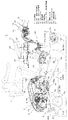
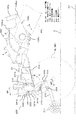
図1は、本発明の移植機の一例として、育苗した野菜の苗、例えばキャベツ等の葉菜の苗を移植する苗移植機1の概略側面図であり、図2は、図1に示す苗移植機1の概略平面図である。また、図3は、苗移植機1の昇降シリンダ50、ローリングシリンダ60、及び左スイングアーム132L等を示す左側面図である。
FIG. 1 is a schematic side view of a
本実施の形態の苗移植機1は、図1、図2、図3に示す様に、
The
(1)走行車体2の前部に配置されたエンジン3と、
(1) The engine 3 arranged at the front of the traveling
(2)その後に配置された、伝動機構(図示省略)を含むトランスミッションケース4と、
(2) A
(3)走行車体2のメインフレーム2aの前端側の左右両側から前方且つ斜め下方に突き出した支持アーム8aの先端部に回動自在に支持された左右一対の前輪8L、8Rと、
(3) A pair of left and right
(4)走行車体2の後側に配置された、苗を左右一対の植付ホッパ21L、21Rにより畝に植え付ける植付装置20と、
(4) A
(5)植付装置20の左右一対の植付ホッパ21L、21Rに苗を供給するための複数個の苗供給カップ31を平面視で長円周形状のループ状に移動可能に配置した供給装置30と、
(5) A supply device in which a plurality of seedling supply cups 31 for supplying seedlings to a pair of left and
(6)走行車体2の後方に突き出した操縦ハンドル5と、
(6) The
(7)エンジン3及びトランスミッションケース4等を覆うボンネット6の上方であってトランスミッションケース4の真上に配置された、苗トレイ11から供給装置30へ苗を補給する際に作業者が着座可能に設けられた作業座席7と、
(7) An operator can sit when supplying seedlings from the
(8)走行車体2への乗り降りの際や、作業座席7に座った際に作業者が足を置くための、作業座席7と供給装置30との前後間に設けられた床面としてフロアステップ10と、
(8) A floor step provided between the front and rear of the work seat 7 and the
(9)トランスミッションケース4の左右両側において入力軸41を中心として回動可能に取り付けられると共に、エンジン3からの動力を入力軸41から受け付けて内蔵されたチェーン伝動機構(図示省略)により出力軸42に伝達して左右一対の後輪9L、9Rを回動させる左右一対の走行伝動ケース40L、40Rと、
(9) The
(10)車高を調整するために、左右一対の走行伝動ケース40L、40Rを入力軸41を中心として回動させることにより、左右一対の後輪9L、9Rを均等に昇降させる昇降シリンダ50と、
(10) In order to adjust the vehicle height, the pair of left and right traveling
(11)走行車体2の左右の傾斜を解消するために、左右一対の走行伝動ケース40L、40Rの内、左側走行伝動ケース40Lについて、入力軸41を中心として回動させることにより、左側の後輪9Lのみを昇降させるローリングシリンダ60と、
(11) Of the pair of left and right traveling
(12)昇降シリンダ50の伸縮動作を左右一対の走行伝動ケース40L、40Rに伝達し、且つ、ローリングシリンダ60の伸縮動作を左側走行伝動ケース40Lにのみ伝達する、後述する左回動筒状部材130Lと右回動筒状部材130Rのそれぞれの外周面に立設固定された左スイングアーム132L及び右スイングアーム132Rと(図1、図2、図3参照)、
(12) A left-handed rotating tubular member described later, which transmits the expansion / contraction operation of the elevating
(13)走行車体2の前端中央下部に設けられ、後述する切替機構300により使用状態と収納状態の何れかに切り替え可能であると共に、使用状態においては、畝の端部や畝の途切れ部の存在を前輪8L、8Rより前方側において検知する畝検知装置200と(図1、図2参照)、
(13) It is provided at the lower center of the front end of the traveling
(14)畝検知装置200が畝の端部や畝の途切れ部を検知した場合、その検知結果の信号により、畝の不存在を知らせる警告音を発するブザーであって、ボンネット6の内部に配置された警報ブザー12と、を備えている。
(14) When the
なお、畝検知装置200については図面を用いて更に後述する。
The
また、本実施の形態の苗移植機1には、図1に示す様に、左右一対の後輪9L、9Rの駆動を入り切りするメインクラッチ(図示省略)を入り切り操作するメインクラッチレバー13と、左右一対の植付ホッパ21L、21Rの駆動を入り切りする植付切替レバー14と、昇降シリンダ50を作動させて車高を調整するための車高調整レバー15とが、操縦ハンドル5側に設けられている。
Further, as shown in FIG. 1, the
また、本実施の形態の苗移植機1のフロアステップ10側には、作業者が作業座席7に座って苗供給カップ31に苗を供給して植付作業を行っている場合でも、上記メインクラッチレバー13、植付切替レバー14、及び車高調整レバー15の各レバーによる各種操作と同じ操作が行える様にするために、同機能を備えた各種レバー(図示省略)がフロアステップ10付近にそれぞれ設けられている。
Further, even when the worker sits on the work seat 7 and supplies the seedlings to the
上記構成により、本実施の形態の苗移植機1によれば、作業者が操縦ハンドル5を操作し、左右一対の前輪8L、8R、及び後輪9L、9Rを圃場の畝溝U1に案内する。その後、作業者が作業座席7に座ったまま、上記各種レバーを操作し走行車体2を畝U上方を跨ぐ様にして前進走行させながら、苗供給カップ31に苗を供給することにより、苗が順次供給された左右一対の植付ホッパ21L、21Rを上下揺動可能な平行リンク構造を成した上下動機構22により上下に往復動作させながら畝Uに苗を植え付け、植付後の苗を鎮圧輪19により培土することが出来る。
With the above configuration, according to the
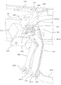
次に、畝検知装置200について、主として図4、図5、図6を用いて更に説明する。
Next, the
図4は、本実施の形態の苗移植機1の前端中央下部に設けられた畝検知装置200(使用状態)を左側面から見た概略拡大側面図である。
FIG. 4 is a schematic enlarged side view of the ridge detection device 200 (used state) provided at the lower center of the front end of the
また、図5は、図4に示す畝検知装置200を右斜め前方から見た部分拡大斜視図である。
Further, FIG. 5 is a partially enlarged perspective view of the
図6は、本実施の形態の苗移植機1の前端中央下部に設けられた畝検知装置200(収納状態)を左側面から見た概略拡大側面図である。
FIG. 6 is a schematic enlarged side view of the ridge detection device 200 (stored state) provided at the lower center of the front end of the
本実施の形態の畝検知装置200は、図4、図5に示す様に、
The
(1)前端部にローラ211を回転可能に設け、当該ローラ211の外周面を畝Uの表面に接触可能に保持した長板状のローラアーム210と、
(1) A long plate-shaped
(2)ローラ211が畝Uの表面に沿って回転しながら上下揺動可能となる様に、ローラアーム210の後端部を、それぞれの先端部である第1先端部221aと第2先端部231a(図5参照)により、異なる位置で回動可能に保持するリンク構成の第1アーム部材220と第2アーム部材230と、
(2) The rear end portions of the
(3)第1アーム部材220の第1基部221bを、当該第1基部221bに固定されたセンサピン222により、側面視で、長孔241の前端部241aが後端部241bより上方に位置する前上がり姿勢の略への字形状の長孔241(図4、図6参照)に沿って移動可能に保持する取付ステー240であって、その上端のL曲げ部242(図5参照)がメインフレーム2aの前端中央下部に固定されており、当該取付ステー240において長孔241より後方に固定された第2上回動軸232により、第2アーム部材230の第2基部231bを回動可能に保持する取付ステー240と、
(3) Before the
(4)第1基部221bに固定されたセンサピン222が略への字形状の長孔241の後端部241b(図4参照)に移動することにより、畝の端部や畝の途切れ部の存在を検知し、検知信号を制御部(図示省略)に出力するセンサユニット250と、
(4) The presence of the edge of the ridge and the break of the ridge by moving the
(5)センサユニット250の下面を固定して、取付ステー240に取り付けるためのセンサ取付プレート260と、を備えている。
(5) A
また、本実施の形態では、畝検知装置200が使用状態にある場合(図4参照)、ローラ211は、左右一対の前輪8L、8Rの前端部より前方側に位置し、畝検知装置200が収納状態にある場合(図6参照)、ローラ211は、左右一対の前輪8L、8Rの前端部より後方側に位置する。
Further, in the present embodiment, when the
上記構成により、本実施の形態の苗移植機1では、畝検知装置200が使用状態にある場合(図4参照)、ローラ211が左右一対の前輪8L、8Rの前端部より前方側に位置することにより、畝検知装置200が畝の端部や途切れ部分をより早く検知することができると共に警報ブザー12がより早い時点で作動するので、作業者は、警報ブザー12の作動後における苗移植機1の走行の停止や植付作業の停止の操作を従来よりも余裕をもって行うことが出来る。
According to the above configuration, in the
また、畝検知装置200が使用状態にある場合(図4参照)、ローラ211が左右一対の前輪8L、8Rの前端部より前方側に位置することにより、畝検知装置200が畝の端部や途切れ部分をより早く検知することができるので、畝端や畝の途切れ部分で苗移植機1の走行や植付作業を停止させやすく、余分な苗の植付や、余分な距離の走行が防止される。
When the
また、畝検知装置200が収納状態にある場合(図6参照)、ローラ211は、左右一対の前輪8L、8Rの前端部より後方側に位置することにより、ローラ211が左右一対の前輪8L、8Rの前端部よりも前側に突出することがないので、前方の障害物に前輪よりも先に接触して破損することが防止される。
When the
なお、畝検知装置200を使用状態と収納状態の何れかに切り替える切替機構300については後述する。
The
また、上記第1先端部221aと第2先端部231a(図5参照)は、ローラアーム210の片側、即ち右側面側において回転可能に連結されており、第1先端部221aは、ローラアーム210の右側面との間に第1スペーサ223(図5参照)を介在させることにより、所定の距離を隔てた状態で連結されている。
Further, the
また、第2アーム部材230の第2基部231b(図4参照)は、取付ステー240に固定された第2上回動軸232を回動中心とすると共に、取付ステー240の左側面との間に第2スペーサ(図示省略)を介在させることにより、取付ステー240の左側面から所定の距離を隔てた状態で連結されている。
Further, the
これにより、第1アーム部材220と第2アーム部材230は、左右方向に互いに位置ずれして配置されているので、畝検知装置200が使用状態及び収納状態の何れの状態においても互いに干渉することが防止される。
As a result, the
また、第1アーム部材220の長手方向中央位置と、第2アーム部材230の第2基部231aの近傍位置とを連結する引っ張りスプリング270(図4参照)が、第1アーム部材220を常時下方に付勢する様に設けられている。
Further, a tension spring 270 (see FIG. 4) that connects the central position of the
これにより、引っ張りスプリング270の縮もうとする復元力で第1アーム部材220が常時下方に引き下げられ、ローラアーム210の先端側が常時畝面に接触する方向に回動するので、ローラ211が畝面から離れることを防止出来、畝端や畝の途切れ部分を検知し損ねることが防止出来る。
As a result, the
また、ローラ211が畝面に強く押し返されたり、石などに接触したりして付勢力以上の負荷がかかると収納位置に向かって第1アーム部材220及び第2アーム部材230を回動させてローラ211を逃がすことができるので、畝検知装置200の破損が防止される。
Further, when the
また、センサユニット250の左側面から回動可能に突き出した回動軸(図示省略)には、センサアーム251が固定されており、そのセンサアーム251の先端側には細長い切り欠き部252が形成されている(図5参照)。
A
本実施の形態の畝検知装置200では、センサアーム251が初期位置に位置するとき(即ち、このときのセンサユニット250は非検知状態である)の切り欠き部252の中央部付近から先端部に亘る領域は、長孔241の中央部付近から前端部241aに亘る緩やかな円弧形状の領域と、側面視で概ね重複する位置関係となる様に調整されている。
In the
これにより、ローラ211が使用状態において畝Uの表面に追従して移動しているときは、多少の上下動があっても、センサピン222の移動範囲は、長孔241の中央部付近から前端部241aに亘る緩やかな円弧形状の領域内に留まるので、センサアーム251の上下の移動範囲は小さく、センサユニット250は非検知状態を維持する。このときのセンサピン222とセンサアーム251の位置関係を図5では、二点鎖線で表した。
As a result, when the
これに対して、ローラ211が、例えば畝Uの端部や畝Uの途切れ部分に到達したときは、ローラ211が大きく降下して、第1アーム部材220が大きく下降すると共にセンサピン222が長孔241の後端部241bにまで移動するので、センサピン222に押し下げられたセンサアーム251は所定の回動範囲を超えて下方に回動するので、センサユニット250は、畝Uの不存在を検知することが出来る。このときのセンサピン222とセンサアーム251の位置関係を図5では、実線で表した。
On the other hand, when the
次に、畝検知装置200を使用状態と収納状態の何れかに切り替える切替機構300について、主として図4〜図6を用いて説明する。
Next, the
本実施の形態の苗移植機1における切替機構300は、図4に示す様に、
As shown in FIG. 4, the
(1)上述した左スイングアーム132Lと、
(1) With the above-mentioned
(2)左スイングアーム132L上の左第2先端部132Lbと、上述した第2アーム部材230上の所定位置とを連結する連結ワイヤー310と、により構成されている。
(2) It is composed of a connecting
本実施の形態の苗移植機1では、昇降シリンダ50の昇降ピストンロッド52(図3参照)が縮む方向に最大限まで移動することにより、左右のスイングアーム132L、132Rが矢印A方向(図4参照)に最大角度まで回動し、これに連動して左右一対の走行伝動ケース40L、40Rが矢印A方向に最大角度まで回動し、車高が最大高さに達する様に構成されている。
In the
上記構成により、左スイングアーム132Lが矢印A方向(図4参照)に最大角度まで回動すると、左スイングアーム132L上の左第2先端部132Lbに後端部が連結された連結ワイヤー310が矢印B方向(図4参照)に引っ張られるので、連結ワイヤー310の前端部が連結された第2アーム部材230は、第2上回動軸232を回動中心として矢印C方向(図4参照)に回動する。
With the above configuration, when the
第2アーム部材230の回動開始に伴って、互いにリンク構成を成している第1アーム部材220もセンサピン222を回動中心として矢印C方向(図4参照)に回動を開始するが、この回動に伴って、センサピン222は、長孔241の前端部241aに移動する様に調整されている。
Along with the start of rotation of the
そして、左スイングアーム132Lが矢印A方向(図4参照)に最大角度まで回動することに連動して、第1アーム部材220と第2アーム部材230が矢印C方向に回動することにより、それらに連結されているローラアーム210も同様に矢印C方向に上昇し、ローラ211と共に収納位置にて停止する(図6参照)。
Then, the
なお、第1アーム部材220の矢印C方向への回動に際して、センサピン222が長孔241の前端部241aに移動することにより、センサアーム251は初期位置(非検知状態)から大きく移動することが無いので、センサユニット250が検知状態になることは無い。
When the
また、第1アーム部材220の第1基部221bのセンサピン222の中心位置と、第2アーム部材230の第2基部231bを回動可能に支持する第2上回動軸232の中心位置との側面視での距離を第1間隔W1とし、第1アーム部材220の第1先端部221aを回動可能に支持する第1下回動軸224の中心位置と、第2アーム部材230の第2先端部231aを回動可能に支持する第2下回動軸234の中心位置との側面視での距離を第2間隔W2とした場合、センサピン222が長孔241のどの位置に位置するかに関わらず第1間隔W1が第2間隔W2より広くなる様に設定されている(図4参照)。
Further, the side surface between the center position of the
これにより、第1アーム部材220と第2アーム部材230を矢印C方向に回動させて、ローラ211を収納状態にするとき、第1間隔W1が第2間隔W2以下の場合に比べて、ローラ211を機体の下面により近い位置まで上昇させることができるので、ローラ211が地面に接触することが防止される(図4、図6参照)。
As a result, when the
また、第1アーム部材220におけるセンサピン222の中心位置と第1下回動軸224の中心位置との側面視での距離は、第2アーム部材230における第2上回動軸232の中心位置と第2下回動軸234の中心位置との側面視での距離よりも長く設定されている。これにより、上記の場合と同様に、ローラ211を収納状態にするとき、ローラ211を機体の下面により近い位置まで上昇させることができるので、ローラ211が地面に接触することが防止される(図4、図6参照)。
Further, the distance between the center position of the
なお、車高を最大高さに移行させる操作としては、作業者が操縦ハンドル5側に立っている場合には、上述した植付切替レバー14による「切り」の操作と、車高調整レバー15による「最大高さ設定」の操作が挙げられ、また、作業者が作業座席7に座って所定の作業を行っている場合には、上述した様に、植付切替レバー14、及び車高調整レバー15等と同じ機構を備えた各種レバー(図示省略)による上記と同様の操作が挙げられる。
As the operation for shifting the vehicle height to the maximum height, when the operator is standing on the control handle 5 side, the above-mentioned "cutting" operation by the
これらのレバーを操作することにより、植付ホッパ21L、21Rによる植付作業は停止されるので、本実施の形態の苗移植機1では、これらのレバー操作に連動して、自動的に畝検知装置200が使用状態から収納状態に切り換わり、ローラ211が、左右一対の前輪8L、8Rの前端部よりも後方側であって、且つ、走行車体2の下部に収納される様にした。
By operating these levers, the planting work by the
一方、作業者が、植付切替レバー14又はそれと同機能のレバーを「切り」から「入り」に切り替える操作を行ったり、或いは、車高調整レバー15又はそれと同機能のレバーを「最大高さ設定」から「植付高さ設定」に切り替える操作を行うことにより、左スイングアーム132Lは、左側面視で、矢印A方向とは逆向き、即ち反時計回りの方向に回動するので、連結ワイヤー310が矢印B方向とは逆方向に移動して弛むので、収納状態にあった第1アーム部材220、第2アーム部材230、ローラアーム210及びローラ211は、自重により矢印Cとは逆方向に回動して、使用状態になり、ローラ211は、左右一対の前輪8L、8Rの前端部よりも前方側に位置して畝Uの表面に接地される(図4参照)。これにより、植付作業を開始することが可能となる。
On the other hand, the operator performs an operation of switching the
なお、上述した左スイングアーム132Lと、右スイングアーム132Rについて更に説明する。
The
即ち、上述した左スイングアーム132Lと、右スイングアーム132Rは、トランスミッションケース4の外壁面部の左右両側から突き出した略円筒状の左フランジ部4bLと、右フランジ部4bR(図2参照)のそれぞれの内側に回動可能に遊嵌接続された左回動筒状部材130Lと、右回動筒状部材130Rのそれぞれの外周面に立設固定された同一形状のプレートである。左回動筒状部材130Lと、右回動筒状部材130Rの機体外側に向かうそれぞれの先端部に固定された鍔状の固定プレート131に対して、左側走行伝動ケース40Lの入力軸41側のケーシング部と、右側走行伝動ケース40Rの入力軸41側のケーシング部とが、それぞれ固定されている(図2参照)。また、左回動筒状部材130Lと、右回動筒状部材130Rのそれぞれの内部空間には、エンジン2からの動力を伝達するためにトランスミッションケース4の左右両端部から突き出した左右一対の伝動シャフト4aL、4aR(図2参照)が、左右一対の走行伝動ケース40L、40R(図2参照)の入力軸41にスプライン接続された状態で、それぞれ回動自在に収納されている。
That is, the above-mentioned
これにより、昇降シリンダ50が伸縮動作すると、これに連動して、左右一対のスイングアーム132L、132Rが、側面視で反時計回り又は時計回りに回動すると共に、左回動筒状部材130Lと右回動筒状部材130Rとが同様に回動するので、左右一対の走行伝動ケース40L、40Rが入力軸41を回動中心として反時計回り又は時計回りに回動することで車高が変化する。なお、昇降シリンダ50が縮むことにより、図3に示す左スイングアーム132Lが側面視で時計回りに回動すると車高は高くなる。
As a result, when the elevating
次に、上述した昇降シリンダ50、及びローリングシリンダ60について説明する。
Next, the elevating
即ち、上述した昇降シリンダ50は、図3に示す様に、その下端部51aが、左右に設けられたメインフレーム2aの平面視で左右幅の略中央位置に連結されると共に側面視で前上がり姿勢に配置されており、その上端側に昇降ピストンロッド52が伸縮可能に設けられている。また、昇降ピストンロッド52の先端部には、背面視で略T字形状の第1連結アーム110が固定され、その第1連結アーム110の左右両方向に伸びた円筒状のアームの内、左側アーム121Lの先端部121Laに側面視で略逆L字形状の左連結プレート部材120Lが回動可能に連結されていると共に、上記円筒状のアームの内、右側アーム(図示省略)の先端部(図示省略)に右連結プレート部材120Rが取り付けられている。
That is, as shown in FIG. 3, the
また、左連結プレート部材120Lの一端部120Laと、上述した左スイングアーム132Lの左第1先端部132Laとは、左連結ロッド140Lにより回動可能に連結されている(図3参照)。また、右連結プレート部材120Rの一端部120Ra(図3参照)と、上述した右スイングアーム132Rの右第1先端部132Ra(図2参照)とは、右連結ロッド140R(図3参照)により回動可能に連結されている。
Further, one end 120La of the left connecting
更にまた、上述したローリングシリンダ60は、その下端部61aが、トランスミッションケース4の左側の壁面部に回動可能に連結されていると共に側面視で後上がり姿勢に配置されており、その上端側にローリングピストンロッド62が伸縮可能に設けられている。また、ローリングピストンロッド62の先端部62aは、上述した左連結プレート部材120Lの他端部120Lbと回動可能に連結されている。
Furthermore, in the rolling
上記構成により、昇降シリンダ50の昇降ピストンロッド52が伸縮すると、図3に示す様に、第1連結アーム110の左右両端に設けられた左連結プレート部材120Lと、右連結プレート部材120Rが上昇又は降下するので、左連結ロッド140Lと、右連結ロッド140Rのそれぞれに連結された左右一対のスイングアーム132L、132Rが、これに連動して、側面視で反時計回り又は時計回りに回動することで、上述した通り、左右一対の走行伝動ケース40L、40Rが入力軸41を回動中心として反時計回り又は時計回りに回動する。これにより、車高を調整することが出来る。
With the above configuration, when the elevating
また、上記構成により、ローリングシリンダ60のローリングピストンロッド62が伸縮すると、図3に示す様に、その先端部62aが連結された左連結プレート部材120Lが、左側アーム121Lの先端部121Laを回動中心として、側面視で反時計回り又は時計回りに回動するので、左連結ロッド140Lに連結された左スイングアーム132Lだけが、これに連動して、側面視で時計回り又は反時計回りに回動することで、左側走行伝動ケース40Lだけが入力軸41を回動中心として時計回り又は反時計回りに回動する。これにより、走行車体2の左右の傾斜を解消することが出来る。
Further, according to the above configuration, when the rolling
なお、本実施の形態の走行車体2は、本発明の走行車体の一例にあたり、本実施の形態の植付装置20は、本発明の植付装置の一例にあたる。また、本実施の形態の供給装置30は、本発明の供給装置の一例にあたり、本実施の形態の畝検知装置200は、本発明の畝検知装置の一例にあたる。また、本実施の形態の警報ブザー12は、本発明の報知装置の一例にあたり、本実施の形態の切替機構300は、本発明の切替機構の一例にあたる。
The traveling
また、本実施の形態のローラ211は、本発明の接触部材の一例にあたる。また、本実施の形態の第1アーム部材220と第2アーム部材230とを含む構成は、本発明の保持機構の一例にあたる。また、本実施の形態のセンサユニット250は、本発明のセンサユニットの一例にあたる。また、本実施の形態の第1アーム部材220は、本発明の第1アーム部材の一例にあたり、本実施の形態の第2アーム部材230は、本発明の第2アーム部材の一例にあたる。
Further, the
また、本実施の形態の第1先端部221aは、本発明の第1先端部の一例にあたり、本実施の形態の第1基部221bは、本発明の第1基部の一例にあたる。また、本実施の形態の第2先端部231aは、本発明の第2先端部の一例にあたり、本実施の形態の第2基部231bは、本発明の第2基部の一例にあたる。
Further, the
また、本実施の形態の左右一対の走行伝動ケース40L、40Rは、本発明の走行伝動ケースの一例にあたり、本実施の形態の左スイングアーム132Lは、本発明の回動アーム部材の一例にあたる。また、本実施の形態の連結ワイヤー310は、本発明の連結部材の一例にあたり、本実施の形態の長孔241は、本発明の長孔の一例にあたる。また、本実施の形態の引っ張りスプリング270は、本発明の付勢部材の一例にあたる。
Further, the pair of left and right traveling
なお、上記実施の形態では、本発明の接触部材の一例としてローラ211を用いた場合について説明したが、これに限らず例えば、畝Uの表面を滑走可能に形成された板状部材であっても良い。
In the above embodiment, the case where the
また、上記実施の形態では、切替機構300として左スイングアーム132Lの回動動作に連動させる場合について説明したが、これに限らず例えば、植付切替レバー14の「入り切り」操作に連動させても良い。この構成の場合、例えば、上述した連結ワイヤー310の後端部を植付切替レバー14に連結し、且つ、連結ワイヤー310の前端部を第1アーム部材220又は第2アーム部材230の何れか一方に連結することにより、植付切替レバー14を「切り」操作することでローラ211を収納状態にし、また、「入り」操作することでローラ211を使用状態に切り替える構成としても良い。この場合でも上記と同様の効果を発揮する。
Further, in the above embodiment, the case where the
また、上記実施の形態では、連結ワイヤー310の前端部が第2アーム部材230に連結されている場合について説明したが、これに限らず例えば、第1アーム部材220又はローラアーム210に連結されていても良い。
Further, in the above embodiment, the case where the front end portion of the connecting
また、上記実施の形態では、左スイングアーム132Lの機能として、入力軸41を回動中心として左側走行伝動ケース40Lを反時計回り又は時計回りに回動することで車高を変化させる機能に加えて、連結ワイヤー310で第2アーム部材230と連結することでローラ211を使用状態と収納状態の何れかに切り替える機能をも兼ねた場合について説明したが、これに限らず例えば、左スイングアーム132Lとは別のプレート部材(図示省略)を左回動筒状部材130L(図2参照)の外周面に固定した構成としても良い。
Further, in the above embodiment, as a function of the
また、上記実施の形態では、トランスミッションケース4の左側に配置されたローリングシリンダ60の伸縮動作に連動して、左スイングアーム132Lが入力軸41を中心として回動することにより、走行車体2の左右の傾斜を解消する構成とし、且つ、その左スイングアーム132Lの回動動作に連動して、畝検知装置200の使用状態(使用位置)と収納状態(収納位置)とが切り替えられる構成について説明したが、これに限らず例えば、ローリングシリンダ60をトランスミッションケース4の右側に配置し、ローリングシリンダ60の伸縮動作に連動して、右スイングアーム132Rが入力軸41を中心として回動する構成としても良い。この構成によれば、左スイングアーム132Lは、ローリングシリンダ60の伸縮動作に連動して回動することが無く、昇降シリンダ50の伸縮動作にのみ連動して回動するので、左スイングアーム132Lに連結ワイヤー310を介して連結された畝検知装置200の上記切替動作を安定させることが出来る。
Further, in the above embodiment, the
また、上記実施の形態では、トランスミッションケース4の左側に配置されたローリングシリンダ60の伸縮動作に連動して、左スイングアーム132Lが入力軸41を中心として回動することにより、走行車体2の左右の傾斜を解消する構成とし、且つ、その左スイングアーム132Lの回動動作に連動して、畝検知装置200の使用状態(使用位置)と収納状態(収納位置)とが切り替えられる構成について説明したが、これに限らず例えば、切替機構300の連結ワイヤー310の後端部を左スイングアーム132Lに代えて右スイングアーム132Rに連結する構成としても良い。この構成によれば、右スイングアーム132Lは、ローリングシリンダ60の伸縮動作に連動して回動することが無く、昇降シリンダ50の伸縮動作にのみ連動して回動するので、右スイングアーム132Rに連結ワイヤー310を介して連結された畝検知装置200の上記切替動作を安定させることが出来る。
Further, in the above embodiment, the
また、上記実施の形態では、本発明の報知装置の一例として警報ブザー12を備えた場合について説明したが、これに限らず例えば、警報音に代えて注意喚起の音声メッセージを発する装置であっても良いし、或いは、警報ランプが点滅する構成としても良い。
Further, in the above-described embodiment, the case where the
また、上記実施の形態で説明したセンサユニット250としては、ポテンショメータを用いても良いし、リミットスイッチを用いても良く、センサの構造には限定されない。
Further, as the
また、上記実施の形態では、センサユニット250は、畝の端部や畝の途切れ部の存在を検知する、即ち、畝Uの不存在を検知して畝不存在信号を出力し、制御部はその畝不存在信号を受け付けると警告ブザー12等の報知装置を作動させるための信号を出力する場合について説明したが、これに限らず例えば、センサユニット250は、ローラ211が畝Uの表面に追従して上下動している状態において畝Uの存在を示す畝存在信号を出力し続ける構成とし、制御部はその畝存在信号を受け付けなくなった状況が生じると畝Uの不存在が発生したと判定して、警告ブザー12等の報知装置を作動させるための信号を出力する構成としても良い。
Further, in the above embodiment, the
また、上記実施の形態では、センサピン222が長孔241のどの位置にあっても、第1間隔W1が、第2間隔W2より広くなる様に設定されている(図4参照)ものとして説明したが、これに限らず例えば、センサピン222が長孔241の前端部241aに位置するときのセンサピン222の中心位置と、上述した第2上回動軸232の中心位置との側面視での距離を第1間隔W1とした場合において、当該第1間隔W1が第2間隔W2より広くなる様に設定された構成でも良い。
Further, in the above embodiment, it is assumed that the first distance W1 is set to be wider than the second distance W2 regardless of the position of the
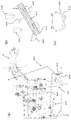
また、上記実施の形態では、植付後の苗を鎮圧輪19を用いて培土する構成について説明したが、これに限らず例えば、鎮圧輪19に代えて、らっきょう等の移植において、植付後の植付穴を埋めるための穴埋め機構400を備えても良い。この構成の場合、図7(a)〜図7(c)に示す様に、ベースプレート410及び土寄せ板420は、土を寄せ易く且つ抜け易くするために、進行方向に対して45°前傾斜状態で取付アーム430に組み付けられている。図7(a)は、穴埋め機構400を示す概略側面図であり、図7(b)は、穴埋め機構400を左後方から見た概略部分斜視図であり、図7(c)は、ベースプレート410に土寄せ板420が取り付けられた状態を上面から見た概略図である。なお、上記実施の形態で説明した構成と同じものには同じ符号を付した。
Further, in the above embodiment, the configuration in which the seedlings after planting are cultivated by using the
また、図7(a)、図7(b)に示す様に、取付アーム430の前端部は走行車体2の後端部に連結されており、取付アーム430の後端部は植付ホッパ21L、21Rの後方に伸びており、その後端部にベースプレート410の中央部が固定されており、ベースプレート410の左右両側に土寄せ板420がボルトにより位置調整可能に取り付けられている。
Further, as shown in FIGS. 7A and 7B, the front end of the mounting
即ち、ベースプレート410には、図7(b)に示す様に、左右方向に伸びたスリット411が、上下方向に複数形成されている。これらのスリット411は、ボルトを挿入して土寄せ板420を固定するためのものである。このスリット411により、複数のスリット411の内のどのスリットを使用するかによって、土寄せ板420の高さを調整することが出来る。図7(b)に示す様に、土寄せ板420をベースプレート410の最下段のスリット411の左右両側寄りに固定することにより、土を中央部に出来る空間へ逃がすことが出来る。また、植付条の位置、即ち、左右の植付ホッパ21L、21Rの位置よりやや外寄りの位置に土寄せ板420を位置決めしてボルトで固定することで、左右方向の位置決めも容易に行える。
That is, as shown in FIG. 7B, the
また、土寄せ板420は、図7(c)に示す様に、機体中央から左右方向に45°傾斜しており、土を集めやすい構成としている。また、取付アーム430は、図7(a)に示す様に、駐車スタンド500との干渉を防止するために、側面視で略L字形状を成している。この略L字形状は、取付アーム430の取付基部、即ち回動支持部から左右の植付ホッパ21L,21Rよりも機体後側位置までの前後直線部と、この直線部の終端で機体下方に屈曲してベースプレート410に向かう上下直線部で構成され、駐車スタンド500は、非使用時に取付アーム430の基部側の下方空間に収まる構成とする。これにより、植付作業時に駐車スタンド500を走行の妨げにならない位置に収納できるので、駐車スタンド500が下方回動して走行の抵抗になることが防止される。
Further, as shown in FIG. 7C, the
また、土寄せ板420は、ベースプレート410を含む自重により圃場に沈ませることが出来るし、又は、ウエイトを付けて沈ませることも出来る。
Further, the
また、上記実施の形態では、切替機構300によりローラ211を使用状態と収納状態の何れかに切り替える構成について説明したが、これに加えて、植付切替レバー14を切位置に操作すると、ワイヤ(図示省略)がセンサピン222を略への字形状の長孔241の機体上側方向(即ち、前端部241a側(図4、図5参照))に引き上げ、センサユニット250による検知をオフにする構成としても良い。この構成により、植付クラッチを切状態にしているときは畝が途切れていても警報ブザー12を鳴らないようにすることが出来る。
Further, in the above embodiment, the configuration in which the
即ち、植付クラッチが切状態となる移動時には、基本的に作業者は作業座席7に座らず、機体後部の操縦ハンドル5側に立つので、進路上を目視しながら機体の操縦を行うことが出来る点や、その時には苗を植え付けていないので、畝が途切れていても警報ブザー12で報知する必要性が無い点等を考慮した構成である。なお、苗移植機1を圃場に持ち込むまでの移動等、距離の長い移動では、ローラ211等を引き摺って壊さないようにするために、切替機構300によりローラ211を収納状態にするのに対して、ここで説明した、植付クラッチを切状態にしているときは畝が途切れていても警報ブザー12を鳴らないようにするのは、旋回時や次の畝への移動時等、移動距離が短く、ローラ211を収納状態にしないときに警報ブザー12を鳴りっ放しにしないためのものである。
That is, when the planting clutch is disengaged, the operator basically does not sit on the work seat 7 but stands on the control handle 5 side at the rear of the machine, so that the machine can be operated while visually observing the course. It is configured in consideration of the points that can be done and the fact that there is no need to notify with the
本発明にかかる移植機は、報知装置の作動後における移植機の走行の停止や植付作業の停止の操作を従来より余裕をもって行うことが出来るので、余分な苗の植付や、余分な距離の走行が防止され、移植機として有用である。 Since the transplanter according to the present invention can stop the running of the transplanter and stop the planting work after the notification device is activated, it is possible to plant extra seedlings and an extra distance. It is useful as a transplanter because it prevents the vehicle from running.
1、201 苗移植機
2 走行車体
3 エンジン
4 トランスミッションケース
5 操縦ハンドル
6 ボンネット
7 作業座席
8L、8R 左右一対の前輪
9L、9R 左右一対の後輪
10 フロアステップ
20 植付装置
30 供給装置
40L、40R 左右一対の走行伝動ケース
50 昇降シリンダ
60 ローリングシリンダ
132L、132R 左右のスイングアーム
200 畝検知装置
211 ローラ
310 連結ワイヤー
1,201
Claims (5)
前記走行車体(2)に設けられ、移植対象物を畝に植え付ける植付装置(20)と、
前記植付装置(20)に前記移植対象物を供給する供給装置(30)と、
前記畝の存在又は不存在を検知する畝検知装置(200)と、
前記畝検知装置(200)による検知結果に基づいて、前記畝の不存在を知らせる報知装置(12)と、
前記畝検知装置(200)を使用状態と収納状態の何れかに切り替える切替機構(300)と、を備え、
前記畝検知装置(200)は、
前記畝の表面に接触可能に設けられた接触部材(211)と、
前記接触部材(211)を前記畝の表面に沿って上下揺動可能に保持する保持機構(220、230)と、
前記接触部材(211)の動作に基づいて、前記畝の存在又は不存在を検知するセンサユニット(250)と、を有し、
前記畝検知装置(200)が前記切替機構(300)により切り替えられて前記使用状態にある場合、前記接触部材(211)は、前記走行装置の前端部よりも前方側に位置し、
前記畝検知装置(200)が前記切替機構(300)により切り替えられて前記収納状態にある場合、前記接触部材(211)は、前記走行装置の前記前端部よりも後方側に位置する、ことを特徴とする移植機。 The traveling device provided on the traveling vehicle body (2) and
A planting device (20) provided on the traveling vehicle body (2) for planting an object to be transplanted in a ridge.
A supply device (30) that supplies the implant target to the planting device (20),
A ridge detection device (200) that detects the presence or absence of the ridge, and
Based on the detection result by the ridge detection device (200), the notification device (12) for notifying the absence of the ridge, and
The ridge detection device (200) is provided with a switching mechanism (300) for switching between a used state and a stored state.
The ridge detection device (200)
A contact member (211) provided so as to be in contact with the surface of the ridge,
Holding mechanisms (220, 230) for holding the contact member (211) so as to swing up and down along the surface of the ridge.
It has a sensor unit (250) that detects the presence or absence of the ridges based on the operation of the contact member (211).
When the ridge detection device (200) is switched by the switching mechanism (300) and is in the used state, the contact member (211) is located on the front side of the front end portion of the traveling device.
When the ridge detection device (200) is switched by the switching mechanism (300) and is in the retracted state, the contact member (211) is located on the rear side of the front end portion of the traveling device. A featured transplanter.
第1基部(221b)が前記走行車体(2)に回動可能に連結され、且つ、第1先端部(221a)が前記接触部材(211)に回動可能に連結された第1アーム部材(220)と、
第2基部(231b)が前記走行車体(2)に回動可能に連結され、且つ、第2先端部(231a)が前記接触部材(211)に回動可能に連結された第2アーム部材(230)と、を有し、
前記第1基部(221b)と前記第2基部(231b)は、前後方向に第1間隔(W1)を有して前記走行車体に連結されており、且つ、前記第1先端部(221a)と前記第2先端部(231a)は、前記前後方向に前記第1間隔(W1)より狭い第2間隔(W2)を有して前記接触部材(211)に連結されている、ことを特徴とする請求項1記載の移植機。 The holding mechanism (220, 230)
First base portion (221b) is pivotably connected to said vehicle body (2), and the first arm member first end (221a) is pivotally connected to said contact member (211) ( 220) and
The second base (231b) is pivotably connected to said vehicle body (2), and, second arm member second distal portion (231a) is pivotally connected to said contact member (211) ( 230) and
The first base portion (221b) and said second base (231b) is coupled to the vehicle body a first distance (W1) in the longitudinal direction and the first distal portion and (221a) The second tip portion (231a) is connected to the contact member (211) with a second spacing (W2) narrower than the first spacing (W1) in the front-rear direction. The transplanter according to claim 1.
前記後輪(9L、9R)に駆動力を伝達すると共に、上下方向に回動することで車高を変更する走行伝動ケース(40L、40R)を備え、
前記切替機構(300)は、
前記走行伝動ケース(40L)の前記上下方向の回動に連動して回動する回動アーム部材(132L)と、
前記回動アーム部材(132L)と、前記保持機構(220、230)とを連結する連結部材(310)と、を有し、
前記走行伝動ケース(40L)が前記車高を高くする方向に前記回動した場合、前記回動の程度に基づいて、前記保持機構(220、230)に保持された前記接触部材(211)が上昇することにより、前記畝検知装置(200)が前記使用状態から前記収納状態に切り替えられる、ことを特徴とする請求項1、又は2記載の移植機。 The traveling device has a pair of left and right front wheels (8L, 8R) and a pair of left and right driving wheels (9L, 9R).
It is equipped with a traveling transmission case (40L, 40R) that transmits driving force to the rear wheels (9L, 9R) and changes the vehicle height by rotating in the vertical direction.
The switching mechanism (300)
A rotating arm member (132L) that rotates in conjunction with the vertical rotation of the traveling transmission case (40L), and
It has a connecting member (310) for connecting the rotating arm member (132L) and the holding mechanism (220, 230).
When the traveling transmission case (40L) rotates in the direction of increasing the vehicle height, the contact member (211) held by the holding mechanism (220, 230) is based on the degree of the rotation. The transplanter according to claim 1 or 2, wherein the ridge detection device (200) is switched from the used state to the stored state by ascending.
Priority Applications (1)
| Application Number | Priority Date | Filing Date | Title |
|---|---|---|---|
| JP2017252984A JP6825552B2 (en) | 2017-12-28 | 2017-12-28 | Rice transplanter |
Applications Claiming Priority (1)
| Application Number | Priority Date | Filing Date | Title |
|---|---|---|---|
| JP2017252984A JP6825552B2 (en) | 2017-12-28 | 2017-12-28 | Rice transplanter |
Publications (2)
| Publication Number | Publication Date |
|---|---|
| JP2019118268A JP2019118268A (en) | 2019-07-22 |
| JP6825552B2 true JP6825552B2 (en) | 2021-02-03 |
Family
ID=67305537
Family Applications (1)
| Application Number | Title | Priority Date | Filing Date |
|---|---|---|---|
| JP2017252984A Active JP6825552B2 (en) | 2017-12-28 | 2017-12-28 | Rice transplanter |
Country Status (1)
| Country | Link |
|---|---|
| JP (1) | JP6825552B2 (en) |
Families Citing this family (4)
| Publication number | Priority date | Publication date | Assignee | Title |
|---|---|---|---|---|
| JP7242521B2 (en) * | 2019-12-25 | 2023-03-20 | 株式会社クボタ | transplanter |
| CN114786467B (en) * | 2019-12-25 | 2024-06-28 | 株式会社久保田 | Transplantation machine |
| JP7143865B2 (en) * | 2020-02-26 | 2022-09-29 | 井関農機株式会社 | Remote management system |
| CN115088438B (en) * | 2022-07-20 | 2023-08-18 | 新疆农业大学 | An easy-to-change ridge greenhouse transplanter |
Family Cites Families (7)
| Publication number | Priority date | Publication date | Assignee | Title |
|---|---|---|---|---|
| JP3625887B2 (en) * | 1995-01-20 | 2005-03-02 | ヤンマー農機株式会社 | Transplanter |
| JP3581213B2 (en) * | 1996-04-26 | 2004-10-27 | ヤンマー農機株式会社 | Transplant machine |
| JP3414969B2 (en) * | 1997-03-03 | 2003-06-09 | 株式会社クボタ | Ridge height detector for transplanter |
| JP2001231310A (en) * | 2000-02-24 | 2001-08-28 | Iseki & Co Ltd | Tractor forward / backward switching control device |
| JP2011067135A (en) * | 2009-09-25 | 2011-04-07 | Iseki & Co Ltd | Seedling transplanter |
| JP5843028B2 (en) * | 2015-03-12 | 2016-01-13 | 井関農機株式会社 | Seedling planting machine |
| JP6440576B2 (en) * | 2015-06-08 | 2018-12-19 | 株式会社クボタ | Transplanter |
-
2017
- 2017-12-28 JP JP2017252984A patent/JP6825552B2/en active Active
Also Published As
| Publication number | Publication date |
|---|---|
| JP2019118268A (en) | 2019-07-22 |
Similar Documents
| Publication | Publication Date | Title |
|---|---|---|
| JP6825552B2 (en) | Rice transplanter | |
| JP5531709B2 (en) | Combine cutting height detector | |
| JP7173209B2 (en) | transplanter | |
| JP2011109976A (en) | Seedling transplanter for planting multiple row | |
| JP5276545B2 (en) | Paddy field work vehicle | |
| JP2011030434A (en) | Seedling transplanter | |
| JP2011067135A (en) | Seedling transplanter | |
| JP5298686B2 (en) | Seedling planting machine | |
| JP2011030439A (en) | Riding-type direct sowing machine | |
| JP4862721B2 (en) | Seedling transplanter | |
| JP5391668B2 (en) | Seedling planting machine | |
| JP5018683B2 (en) | Seedling planting machine | |
| JP2013014172A (en) | Working vehicle | |
| JP2014068575A (en) | Seedling transplanter | |
| JP2010124730A5 (en) | ||
| JP5641096B2 (en) | Seedling transplanter | |
| JP6832772B2 (en) | Planting work machine | |
| JP2001245511A (en) | Farm work machine | |
| JP2012152194A (en) | Reaping device | |
| JP2014064541A (en) | Seedling transplanter | |
| JP3509622B2 (en) | Rice transplanter | |
| JP2007117015A (en) | Combine weeding equipment | |
| JP2010075107A (en) | Seedling planter | |
| JP2000245218A (en) | Harvesting machine for root vegetable | |
| JP6878957B2 (en) | combine |
Legal Events
| Date | Code | Title | Description |
|---|---|---|---|
| A621 | Written request for application examination |
Free format text: JAPANESE INTERMEDIATE CODE: A621 Effective date: 20200225 |
|
| A871 | Explanation of circumstances concerning accelerated examination |
Free format text: JAPANESE INTERMEDIATE CODE: A871 Effective date: 20200625 |
|
| A977 | Report on retrieval |
Free format text: JAPANESE INTERMEDIATE CODE: A971007 Effective date: 20201016 |
|
| A975 | Report on accelerated examination |
Free format text: JAPANESE INTERMEDIATE CODE: A971005 Effective date: 20201020 |
|
| A131 | Notification of reasons for refusal |
Free format text: JAPANESE INTERMEDIATE CODE: A131 Effective date: 20201027 |
|
| RD02 | Notification of acceptance of power of attorney |
Free format text: JAPANESE INTERMEDIATE CODE: A7422 Effective date: 20201110 |
|
| A521 | Written amendment |
Free format text: JAPANESE INTERMEDIATE CODE: A523 Effective date: 20201117 |
|
| TRDD | Decision of grant or rejection written | ||
| A01 | Written decision to grant a patent or to grant a registration (utility model) |
Free format text: JAPANESE INTERMEDIATE CODE: A01 Effective date: 20201215 |
|
| A61 | First payment of annual fees (during grant procedure) |
Free format text: JAPANESE INTERMEDIATE CODE: A61 Effective date: 20201228 |
|
| R150 | Certificate of patent or registration of utility model |
Ref document number: 6825552 Country of ref document: JP Free format text: JAPANESE INTERMEDIATE CODE: R150 |