JP6825397B2 - Biometric device, biometric method and biometric program - Google Patents
Biometric device, biometric method and biometric program Download PDFInfo
- Publication number
- JP6825397B2 JP6825397B2 JP2017020458A JP2017020458A JP6825397B2 JP 6825397 B2 JP6825397 B2 JP 6825397B2 JP 2017020458 A JP2017020458 A JP 2017020458A JP 2017020458 A JP2017020458 A JP 2017020458A JP 6825397 B2 JP6825397 B2 JP 6825397B2
- Authority
- JP
- Japan
- Prior art keywords
- touch panel
- contact
- user
- finger
- marks
- Prior art date
- Legal status (The legal status is an assumption and is not a legal conclusion. Google has not performed a legal analysis and makes no representation as to the accuracy of the status listed.)
- Expired - Fee Related
Links
Images


Classifications
-
- G—PHYSICS
- G06—COMPUTING OR CALCULATING; COUNTING
- G06F—ELECTRIC DIGITAL DATA PROCESSING
- G06F21/00—Security arrangements for protecting computers, components thereof, programs or data against unauthorised activity
- G06F21/30—Authentication, i.e. establishing the identity or authorisation of security principals
- G06F21/31—User authentication
- G06F21/32—User authentication using biometric data, e.g. fingerprints, iris scans or voiceprints
-
- G—PHYSICS
- G06—COMPUTING OR CALCULATING; COUNTING
- G06F—ELECTRIC DIGITAL DATA PROCESSING
- G06F3/00—Input arrangements for transferring data to be processed into a form capable of being handled by the computer; Output arrangements for transferring data from processing unit to output unit, e.g. interface arrangements
- G06F3/01—Input arrangements or combined input and output arrangements for interaction between user and computer
- G06F3/03—Arrangements for converting the position or the displacement of a member into a coded form
- G06F3/041—Digitisers, e.g. for touch screens or touch pads, characterised by the transducing means
-
- G—PHYSICS
- G06—COMPUTING OR CALCULATING; COUNTING
- G06V—IMAGE OR VIDEO RECOGNITION OR UNDERSTANDING
- G06V40/00—Recognition of biometric, human-related or animal-related patterns in image or video data
- G06V40/10—Human or animal bodies, e.g. vehicle occupants or pedestrians; Body parts, e.g. hands
- G06V40/14—Vascular patterns
- G06V40/145—Sensors therefor
-
- G—PHYSICS
- G06—COMPUTING OR CALCULATING; COUNTING
- G06V—IMAGE OR VIDEO RECOGNITION OR UNDERSTANDING
- G06V40/00—Recognition of biometric, human-related or animal-related patterns in image or video data
- G06V40/20—Movements or behaviour, e.g. gesture recognition
- G06V40/28—Recognition of hand or arm movements, e.g. recognition of deaf sign language
-
- G—PHYSICS
- G06—COMPUTING OR CALCULATING; COUNTING
- G06V—IMAGE OR VIDEO RECOGNITION OR UNDERSTANDING
- G06V40/00—Recognition of biometric, human-related or animal-related patterns in image or video data
- G06V40/10—Human or animal bodies, e.g. vehicle occupants or pedestrians; Body parts, e.g. hands
- G06V40/107—Static hand or arm
- G06V40/117—Biometrics derived from hands
Landscapes
- Engineering & Computer Science (AREA)
- Theoretical Computer Science (AREA)
- Physics & Mathematics (AREA)
- General Physics & Mathematics (AREA)
- Human Computer Interaction (AREA)
- General Engineering & Computer Science (AREA)
- Computer Security & Cryptography (AREA)
- Health & Medical Sciences (AREA)
- Multimedia (AREA)
- General Health & Medical Sciences (AREA)
- Software Systems (AREA)
- Computer Hardware Design (AREA)
- Vascular Medicine (AREA)
- Computer Vision & Pattern Recognition (AREA)
- Psychiatry (AREA)
- Social Psychology (AREA)
- Image Input (AREA)
- User Interface Of Digital Computer (AREA)
Description
本発明は、生体認証装置、生体認証方法及び生体認証プログラムに関する。 The present invention relates to a biometric authentication device, a biometric authentication method and a biometric authentication program.
端末を介した重要データへのアクセスに際して、セキュリティを確保するために、例えば生体認証が用いられる。生体認証は、指紋、顔、静脈等の生体特徴を用いて本人確認を行う技術である。生体認証では、取得した生体情報を、予め登録しておいた生体情報と比較(又は、照合)し、登録生体情報と一致するか否かに応じて本人確認を行う。なお、比較する生体情報は、生体情報の特徴を表す生体特徴情報であっても良い。 For example, biometric authentication is used to ensure security when accessing important data via a terminal. Biometric authentication is a technique for verifying an identity using biological features such as fingerprints, faces, and veins. In biometric authentication, the acquired biometric information is compared (or collated) with the biometric information registered in advance, and the identity is confirmed according to whether or not it matches the registered biometric information. The biological information to be compared may be biological characteristic information representing the characteristics of the biological information.
一方、携帯端末の携帯性は向上しており、携帯端末のセキュリティ機能の利便性が求められている。しかし、携帯端末を利用する状況によっては、携帯端末を固定したり、安定に保持することが難しい。このため、例えば手のひら静脈認証のように、非接触で生体情報を撮影する場合には、手のブレにより取得される生体情報の品質が劣化する。その結果、本人拒否が発生しやすくなり、生体情報を撮影し直す等に要する操作回数及び操作時間が増大して、携帯端末の利便性が損なわれる。 On the other hand, the portability of mobile terminals is improving, and the convenience of security functions of mobile terminals is required. However, depending on the situation in which the mobile terminal is used, it is difficult to fix the mobile terminal or hold it stably. For this reason, when biometric information is photographed in a non-contact manner, such as palm vein authentication, the quality of the biometric information acquired due to hand shake deteriorates. As a result, the refusal of the person is likely to occur, the number of operations and the operation time required for re-imaging the biometric information are increased, and the convenience of the mobile terminal is impaired.
携帯端末の多くには、タッチパネルが備えられている(例えば、特許文献1)。そこで、利用者の指をタッチパネルに接触させ、携帯端末に対する手の位置を安定させた状態で、生体情報を取得することが提案されている。更に、利用者に、指で接触するべきタッチパネル上の位置を逐次表示することで、効率良く生体情報を取得することも提案されている(例えば、特許文献2)。 Many mobile terminals are provided with a touch panel (for example, Patent Document 1). Therefore, it has been proposed to acquire biometric information by bringing the user's finger into contact with the touch panel and stabilizing the position of the hand with respect to the mobile terminal. Further, it has been proposed to efficiently acquire biological information by sequentially displaying the position on the touch panel to be touched by a finger to the user (for example, Patent Document 2).
しかし、手のサイズは、個人差が大きい。このため、固定的な取得方法又は固定的な入力指示では、手の姿勢が不適切な状態で撮影を強いられ、手のひらを安定して撮影することが難しいため、生体認証の認証精度の低下を招く可能性がある。例えば、手のひらを撮影する際、手の小さい利用者は、無理に手を広げた状態で撮影を強いられたり、手の大きい利用者は、無理に手をすぼめた状態で撮影を強いられたりする。 However, the size of the hand varies greatly from person to person. For this reason, with a fixed acquisition method or a fixed input instruction, shooting is forced in an inappropriate posture of the hand, and it is difficult to shoot the palm stably, so that the authentication accuracy of biometric authentication is reduced. May be invited. For example, when shooting a palm, a user with a small hand may be forced to shoot with his hands open, and a user with a large hand may be forced to shoot with his hands squeezed. ..
このように、従来の生体認証では、手のひら等の生体部位の生体情報を取得する際に、利用者の生体部位の個人差を考慮していない。このため、無理な姿勢を強いられた等の、不適切な状態で撮影された生体部位を利用して生体認証を行う場合、生体部位を安定して撮影することが難しいため、生体認証の認証精度を向上することは難しい。 As described above, in the conventional biometric authentication, the individual difference of the biological part of the user is not taken into consideration when acquiring the biological information of the biological part such as the palm. For this reason, when biometric authentication is performed using a biological part taken in an inappropriate state such as being forced into an unreasonable posture, it is difficult to stably photograph the biological part, so biometric authentication is performed. It is difficult to improve the accuracy.
従来技術では、利用者の生体部位の個人差を考慮していないため、撮影した生体部位を利用した生体認証の認証精度を向上することは難しい。 In the prior art, it is difficult to improve the authentication accuracy of biometric authentication using the photographed biological part because the individual difference of the biological part of the user is not taken into consideration.
そこで、1つの側面では、生体認証の認証精度を向上することのできる生体認証装置、生体認証方法及び生体認証プログラムを提供することを目的とする。 Therefore, in one aspect, it is an object of the present invention to provide a biometric authentication device, a biometric authentication method, and a biometric authentication program capable of improving the authentication accuracy of biometric authentication.
1つの案によれば、生体センサと、タッチパネルと、前記タッチパネルから出力される、前記タッチパネルへの接触を示す接触信号を入力すると共に、前記タッチパネル上への表示を制御する制御手段とを備え、前記制御手段は、前記タッチパネル上に、利用者が指で接触する位置を指示する複数のマークを表示し、前記接触信号に基づき、前記利用者が指で当該複数のマークに接触したことを検知すると、少なくとも1つのマークを縮小すると共に、前記生体センサが撮影した前記利用者の手の生体情報を取得する生体認証装置が提供される。 According to one proposal, a biological sensor, a touch panel, and a control means for inputting a contact signal output from the touch panel indicating contact with the touch panel and controlling display on the touch panel are provided. The control means displays a plurality of marks indicating a position where the user touches with a finger on the touch panel, and detects that the user has touched the plurality of marks with a finger based on the contact signal. Then, a biometric authentication device is provided that reduces at least one mark and acquires biometric information of the user's hand taken by the biosensor.
一態様によれば、生体認証の認証精度を向上することができる。 According to one aspect, the authentication accuracy of biometric authentication can be improved.
開示の生体認証装置、生体認証方法及び生体認証プログラムでは、タッチパネル上に、利用者が指で接触する位置を指示する複数のマークを表示し、指が当該複数のマークに接触したことを検知すると、少なくとも1つのマークを縮小すると共に、生体センサが撮影した利用者の手の生体情報を取得する。 In the disclosed biometric authentication device, biometric authentication method, and biometric authentication program, when a plurality of marks indicating the position where the user touches with a finger are displayed on the touch panel and it is detected that the finger touches the plurality of marks. , At least one mark is reduced, and biometric information of the user's hand taken by the biometric sensor is acquired.
以下に、開示の生体認証装置、生体認証方法及び生体認証プログラムの各実施例を図面と共に説明する。 Hereinafter, each embodiment of the disclosed biometric authentication device, biometric authentication method, and biometric authentication program will be described with drawings.
生体認証技術は、指紋、顔、手のひら、虹彩、静脈等の個人毎に異なる特徴的な生体情報を用いて本人確認を行う。例えば、手のひら認証は、手のひら静脈、掌紋、掌形等の生体情報を用いて生体認証を行う。以下の説明では、手のひら認証を例に説明するが、生体認証は手のひら認証に限定されるものではない。 The biometric authentication technology performs identity verification using characteristic biometric information such as fingerprints, faces, palms, irises, and veins, which are different for each individual. For example, in palm authentication, biometric authentication is performed using biometric information such as palm veins, palm prints, and palm shapes. In the following description, palm authentication will be described as an example, but biometric authentication is not limited to palm authentication.
一実施例において、以下に説明する生体認証装置は、端末に搭載可能である。端末は、携帯端末であっても良い。従って、端末には、パーソナルコンピュータ、タブレット、スマートフォン等が含まれる。 In one embodiment, the biometric authentication device described below can be mounted on the terminal. The terminal may be a mobile terminal. Therefore, the terminal includes a personal computer, a tablet, a smartphone and the like.
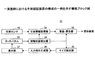
図1は、一実施例における端末のハードウェア構成の一例を示すブロック図である。この例では、端末1は、タブレット、スマートフォン等の携帯端末である。端末1は、図1に示す如く接続されたCPU(Central Processing Unit)11、ROM(Read Only Memory)12、RAM(Random Access Memory)13、入力デバイス14、表示デバイス15、及び生体センサ16を有する。端末1が通信機能を有する場合には、送受信を行う周知の通信部(図示せず)を更に有しても良い。また、端末1がインターネット等の外部のネットワーク(図示せず)と接続する機能を有する場合には、周知のインタフェース(図示せず)を更に有しても良い。
FIG. 1 is a block diagram showing an example of the hardware configuration of the terminal in one embodiment. In this example, the
CPU11は、端末1全体の制御を司る制御部(又は、コンピュータ)の一例である。従って、制御部は、生体認証装置の制御をも司る。ROM12及びRAM13は、記憶部の一例である記憶装置21を形成しても良い。この例では、入力デバイス14及び表示デバイス15は、タッチパネル22に含まれる。
The
CPU11は、ROM12に格納された生体認証プログラムを含むコンピュータプログラムを実行することにより、生体認証装置を含む端末1の種々の機能を実現できる。ROM12は、CPU11が実行するコンピュータプログラム、各種データ等を格納する。ROM12は、プログラムを格納したコンピュータ読み取り可能な記憶媒体の一例である。RAM13は、各種データの他に登録生体情報を格納する。
The
タッチパネル22の入力デバイス14は、利用者の指によるタッチパネル22への接触を示す接触信号を出力してCPU11に入力する機能を有する。タッチパネル22の入力デバイス14が出力する接触信号は、利用者の指が接触したタッチパネル22上の接触位置又は接触位置の座標、接触位置における利用者の指のタッチパネル22上での接触面積、接触位置における利用者の指のタッチパネル22上での接触形状等を示す。タッチパネル22の入力デバイス14は、文字等の入力時に、利用者が指で接触した位置が表す文字等の情報をCPU11に入力する機能も有する。このような接触信号及び文字等の情報を出力するタッチパネル自体は、周知である。CPU11は、接触信号に基づいて、利用者が指でタッチパネル22上をスライド操作していることを、周知の方法で検知可能である。
The
タッチパネル22の表示デバイス15は、文字、図、メッセージ等に加え、後述するように、利用者の指の接触位置を示す複数のマーク、タッチパネル22上の利用者の指の現在位置を含む入力位置、スライド操作する軌跡及び方向等を表示する機能を有する。
The
生体センサ16は、この例では非接触式で生体の部位を撮影する機能を有する。生体センサ16は、少なくともカメラを含み、生体照明光源を含んでも良い。この例では、生体センサ16は、端末1のタッチパネル22と同じ表面の、タッチパネル22の周辺の位置に取り付けられている。
The
生体センサ16は、例えば手のひらの静脈、掌紋、掌形、指の静脈等を撮影するカメラで形成可能である。また、生体センサ16は、例えば手のひらの静脈、指の静脈等を撮影する近赤外波長領域に感度を持つイメージセンサ(又は、カメラ)と近赤外光照明光源とを含む近赤外センサ(又は、近赤外カメラ)で形成可能である。また、生体センサ16は、近赤外波長領域以外の波長領域に感度を持つカメラと、近赤外センサとの両方を含んでも良い。
The
図2は、一実施例における生体認証装置の構成の一例を示す機能ブロック図である。図2に示す生体認証装置31は、生体センサ16からの生体情報が入力される生体情報取得部32と、登録・照合部33と、タッチパネル22からの接触信号等が入力される接触位置検出部34と、サイズ検出部35と、入力指示生成部36と、表示部37とを有する。生体情報取得部32、登録・照合部33、接触位置検出部34、サイズ検出部35、入力指示生成部36及び表示部37は、例えば図1に示すCPU11により形成可能であり、例えばCPU11が形成する制御部に含まれても良い。CPU11は、例えば図1に示す記憶装置21に記憶されている生体認証プログラムを実行することで、生体情報取得部32、登録・照合部33、接触位置検出部34、サイズ検出部35、入力指示生成部36及び表示部37の機能を実現できる。
FIG. 2 is a functional block diagram showing an example of the configuration of the biometric authentication device in one embodiment. The
先ず、生体情報の登録時の動作について説明する。生体情報の登録時、入力指示生成部36は、利用者が指で接触する位置を指示する複数のマークを生成する。後述する複数のマークは、例えば図1に示す記憶装置21にデフォルトとして記憶されていても良い。この場合、入力指示生成部36は、記憶装置21から複数のマークを読み出せば良い。表示部37は、入力指示生成部36が生成した複数のマークを、タッチパネル22上に表示する。利用者が指でタッチパネル22上の複数のマークに接触すると、タッチパネル22が、利用者の指が複数のマークに接触したことを示す接触信号を接触位置検出部34に出力する。接触位置検出部34は、接触信号に基づき、利用者が指で複数のマークの全てに接触したことを検知すると、接触信号をサイズ検出部35に出力する。
First, the operation at the time of registration of biometric information will be described. At the time of registering the biometric information, the input
サイズ検出部35は、接触信号が示すタッチパネル22上での接触位置、接触面積、接触形状等に基づいて、利用者の手のサイズを検出する。手のサイズは、指の長さ、指の太さ、手のひらのサイズ等を含む。入力指示生成部36は、サイズ検出部35が検出した手のサイズに応じて、縮小する少なくとも1つのマークのタッチパネル22上の表示位置を調整し、調整したマークの表示位置の指示を表示部37に出力する。入力指示生成部36は、接触信号が示すタッチパネル22上での接触位置、接触位置における接触面積及び接触位置における接触形状のうち、少なくとも1つに基づいて、複数のマークから利用者が指でスライド操作する軌跡及び方向の少なくとも一方の指示をタッチパネル22に出力しても良い。入力指示生成部36は、利用者が指で接触する位置を指示する複数のマークを生成する際に、サイズ検出部35が検出した手のサイズに基づき、タッチパネル22上の表示位置が調整された、少なくとも1つのマークを縮小する。表示部37は、入力指示生成部36が生成した、縮小された少なくとも1つのマークを含む複数のマークを、タッチパネル22上に表示する。これにより、利用者が指で接触しているタッチパネル22上の複数のマークのうち、少なくとも1つのマークが縮小される。
The
表示部37は、入力指示生成部36から、複数のマークから利用者が指でスライド操作する軌跡及び方向の少なくとも一方の指示が入力されると、スライド操作する軌跡及び方向の少なくとも一方をタッチパネル22上に表示する。つまり、表示部37は、入力指示生成部36が生成した、縮小された少なくとも1つのマークを含む複数のマークと、スライド操作する軌跡及び方向の少なくとも一方を、タッチパネル22上に表示する。接触位置検出部34は、接触信号に基づき、利用者が指で複数のマークからスライド操作していることを検知できる。接触位置検出部34がスライド操作していることを検知すると、生体情報取得部32は、スライド操作中に、生体センサ16が撮影した利用者の手の生体情報を取得する。生体情報取得部32は、スライド操作中、生体センサ16が連続的又は一定間隔で撮影した利用者の手の生体情報を取得しても良い。
When the input
なお、生体センサ16が撮影した利用者の手の生体情報を取得する生体情報取得部32は、生体情報を読み取る期間活性化される生体センサ16から出力される生体情報を、スライド操作中の期間のみ取得しても良い。また、生体情報取得部32は、生体センサ16をスライド操作中の期間のみ活性化して、生体センサ16から出力される生体情報を取得するようにしても良い。
The biometric
このように、接触位置検出部34が接触信号をサイズ検出部35に出力し、サイズ検出部35が検出した利用者の手のサイズに基づいて、入力指示生成部36が入力指示を更新する。表示部37は、入力指示生成部36が出力する更新された入力指示に基づき、複数のマークをタッチパネル22上に表示する。
In this way, the contact
生体情報取得部32は、生体センサ16が撮影した生体情報を登録・照合部33に出力する。登録・照合部33は、生体情報を、例えば図1に示す記憶装置21に登録する。なお、生体情報取得部32が登録・照合部33に出力して登録する生体情報は、生体情報の特徴を表す生体特徴情報であっても良い。生体情報から生体特徴情報を抽出する場合は、周知の方法で生体特徴情報を抽出可能である。サイズ検出部35が手のサイズを検出しているので、登録・照合部33が登録する生体情報は、利用者の手のどの部分に相当するのかがわかる。
The biological
次に、生体情報の認証時の動作について説明する。生体情報の認証時の動作は、登録・照合部33の処理を除き、上記生体情報の登録時の動作と同様である。生体情報の認証時には、例えば図1に示す記憶装置21に登録生体情報が既に登録されている。このため、登録・照合部33は、生体情報の認証時に生体情報取得部32が取得した生体情報を、例えば図1に示す記憶装置21に登録された登録生体情報と照合する。なお、生体情報の特徴を表す生体特徴情報が登録されている場合、生体情報取得部32が登録・照合部33に出力して照合する生体情報は、生体情報の特徴を表す生体特徴情報であっても良い。登録・照合部33は、認証時に取得した生体情報と、登録生体情報とが一致した場合、生体認証が成功したと判定し、利用者の本人であることを表す照合結果を出力する。照合結果は、例えばタッチパネル22に出力して表示しても、周知の方法で音声出力しても良い。
Next, the operation at the time of authentication of biometric information will be described. The operation at the time of authentication of the biometric information is the same as the operation at the time of registration of the biometric information except for the processing of the registration /
生体情報取得部32、接触位置検出部34、サイズ検出部35、入力指示生成部36及び表示部37は、タッチパネル22から出力される、タッチパネル22への接触を示す接触信号を入力すると共に、タッチパネル22上への表示を制御する制御手段の一例を形成可能である。この制御手段は、タッチパネル22上に、利用者が指で接触する位置を指示する複数のマークを表示し、接触信号に基づき、利用者が指で当該複数のマークに接触したことを検知すると、少なくとも1つのマークを縮小すると共に、生体センサ16が撮影した利用者の手の生体情報を取得する。
The biological
この例では、タッチパネル上に指の接触位置を示す複数のマークを表示し、各マーク上への指の接触に応答して、少なくとも1つのマークを縮小させる。これにより、利用者の手のサイズにかかわらず、指の接触位置を指示するマークに、無理な姿勢をとることなく容易に複数の指を接触可能となる。また、利用者が複数の指でスライド操作を開始する時には、少なくとも1つのマークが縮小され、利用者の手のサイズに適した、スライド操作する軌跡及び方向の少なくとも一方の指示をタッチパネル上に表示する。この結果、利用者が端末のタッチパネルに複数の指で接触しながら生体認証を行う際に、利用者の手のサイズの個人差に因らず、生体認証の認証精度を向上することができる。
<実施例1>
In this example, a plurality of marks indicating the finger contact position are displayed on the touch panel, and at least one mark is reduced in response to the finger contact on each mark. As a result, regardless of the size of the user's hand, it is possible to easily contact a plurality of fingers with the mark indicating the contact position of the fingers without taking an unreasonable posture. Further, when the user starts the slide operation with a plurality of fingers, at least one mark is reduced, and at least one instruction of the trajectory and direction of the slide operation suitable for the size of the user's hand is displayed on the touch panel. To do. As a result, when the user performs biometric authentication while touching the touch panel of the terminal with a plurality of fingers, the authentication accuracy of the biometric authentication can be improved regardless of the individual difference in the size of the user's hand.
<Example 1>
次に、実施例1について説明する。図3乃至図5は、実施例1によるマークの表示の一例を説明する平面図である。また、図6は、比較例によるマークの表示の一例を説明する平面図である。 Next, Example 1 will be described. 3 to 5 are plan views for explaining an example of displaying the mark according to the first embodiment. Further, FIG. 6 is a plan view illustrating an example of displaying a mark according to a comparative example.
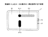
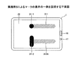
図3は、端末1のタッチパネル22上に、利用者が指で接触する位置を指示する複数のマーク31−1,31−2を表示した初期状態を示す。この例では、マーク31−2のサイズが、マーク31−1のサイズより大きい。また、この例では、マーク31−2は、利用者に無理な姿勢を強いらないよう、図3中縦方向に長くすることでサイズを大きくしている。サイズが小さい方のマーク31−1に対しては、このマーク31−1から利用者が指でスライド操作する軌跡及び方向の少なくとも一方を指示する案内311を表示する。少なくとも1つのマーク31−2を、他のマーク3−1のサイズより大きなサイズで表示するため、利用者は、当該利用者の手のサイズに合わせて、指を置き易い位置でマーク31−1と接触させることができる。生体センサ16は、端末1のタッチパネル22と同じ表面の、タッチパネル22の周辺の位置に取り付けられている。生体センサ16は、少なくともカメラを含み、生体照明光源17を含んでも良い。
FIG. 3 shows an initial state in which a plurality of marks 31-1 and 31-2 indicating the positions where the user touches with a finger are displayed on the
図4は、図3に示す初期状態のタッチパネル22上で、利用者が指でマーク31−1,31−2に接触した状態を示す。この例では、指が接触したマーク31−1,31−2のうち、サイズの大きい方のマーク31−2のサイズを縮小して表示する。また、マーク31−1,31−2上への利用者の指の接触に応答して、スライドする指の図4中縦方向の座標が決定する。これにより、サイズが縮小されたマーク31−2に対しては、このマーク31−2から利用者が指でスライド操作する軌跡及び方向の少なくとも一方を指示する案内312を表示する。
FIG. 4 shows a state in which the user touches the marks 31-1 and 31-2 with his / her finger on the
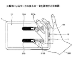
図5は、実施例1における利用者の操作の一例を説明する平面図である。図5中、図3及び図4と同一部分には同一符号を付し、その説明は省略する。図5に示す初期状態ST1では、タッチパネル22上に、利用者が人差し指と親指で接触する位置を指示するマーク31−1,31−2を表示する。この際、利用者の手500のサイズには個人差があるため、親指で接触する位置を指示するマーク31−2がマーク31−1より大きなサイズで表示される。利用者は、人差し指をマーク31−1に接触させた状態で、手500のサイズに合わせたマーク31−2上の位置で親指をマーク31−2に接触させることができる。このため、利用者に無理な姿勢を強いらないように、タッチパネル22上に、指で接触する位置を指示するマーク31−1,31−2を表示することができる。
FIG. 5 is a plan view illustrating an example of the user's operation in the first embodiment. In FIG. 5, the same parts as those in FIGS. 3 and 4 are designated by the same reference numerals, and the description thereof will be omitted. In the initial state ST1 shown in FIG. 5, marks 31-1 and 31-2 indicating the position where the user contacts the index finger and the thumb are displayed on the
図5に示す状態ST2では、初期状態ST1にあるタッチパネル22上で、利用者が指でマーク31−1,31−2に接触した状態を示す。この例では、指が接触したマーク31−1,31−2のうち、サイズの大きい方のマーク31−2のサイズを縮小して表示する。また、サイズが縮小されたマーク31−2に対しては、このマーク31−2から利用者が指でスライド操作する軌跡及び方向の少なくとも一方を指示する案内312を表示する。
The state ST2 shown in FIG. 5 shows a state in which the user touches the marks 31-1 and 31-2 with a finger on the
図5に示す状態ST3では、状態ST2にあるタッチパネル22上で、利用者がマーク31−1,31−2から指をスライド操作した状態を示す。説明の便宜上、スライド操作した分だけ、案内311,312のハーフトーンの表示がマーク31−1,31−2と同じ黒い表示に変化している。また、状態ST3では、利用者の手500が、生体センサ16により手のひらを撮影するのに適した撮影範囲160の位置まで移動しているので、生体センサ16から利用者の生体情報の一例である手のひらの情報を取得する。手のひらの情報は、手のひら静脈、掌紋、掌形等の情報である。
The state ST3 shown in FIG. 5 shows a state in which the user slides a finger from the marks 31-1 and 31-2 on the
一方、図6に示す比較例では、接触前にタッチパネル22上に表示されるマーク31A,31Bのサイズが同じであり、接触直後の状態を示す図4と類似の表示である。また、案内311A,311Bは、対応するマーク31A,31Bが最初に表示されていた位置から、図6中横方向に延びるように表示される。このため、利用者の手500のサイズが、設計時に想定した範囲内のサイズであれば、利用者は指をマーク31A,31Bと比較的容易に接触させることができる。また、利用者が指でスライド操作を行うと、生体センサ16が手のひらを撮影範囲160で撮影できる。しかし、利用者の手500が設計時に想定した範囲外の大きなサイズ又は小さなサイズの場合、利用者は指をマーク31A,31Bに接触させるのに、無理な姿勢を強いられてしまう。また、無理な姿勢のまま利用者が指でスライド操作を行うと、生体センサ16が撮影範囲160で手のひらを良好に撮影できない場合がある。つまり、無理な姿勢によっては、生体センサ16が撮影範囲160で撮影できる手のひらが、タッチパネル22と平行な平面に近い状態ではなく、タッチパネル22に対して傾斜した面であったり、無理な姿勢のため手のひらがすぼまった状態となり、生体認証に適した生体情報を取得することができない。
On the other hand, in the comparative example shown in FIG. 6, the sizes of the
一方、実施例1の場合、図5に示す初期状態ST1では、タッチパネル22上で少なくとも1つのマーク31−2が他のマーク31−1より大きなサイズで表示されるため、利用者が無理な姿勢を強いられることはない。また、自然な姿勢のまま利用者が指でスライド操作を行えるので、生体センサ16が撮影範囲160で手のひらを、手のひらを撮影するのに適した、タッチパネル22と平行な平面に近い状態で良好に撮影できる。このため、生体センサ16からは、生体認証に適した手のひら静脈等の生体情報を取得することができる。
On the other hand, in the case of the first embodiment, in the initial state ST1 shown in FIG. 5, at least one mark 31-2 is displayed on the
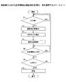
図7は、実施例1における生体情報の登録時の処理の一例を説明するフローチャートである。図7に示す登録処理は、図1に示すCPU11により実行可能である。図7において、ステップS1では、CPU11が、タッチパネル22上に図5に示す初期状態ST1の表示を行い、利用者による入力、即ち、指のマーク31−1,31−2への接触が行われたか否かを判定する。ステップS1の判定結果がYESになると、ステップS2では、CPU11が、タッチパネル22からの接触信号に基づき、利用者が指でタッチパネル22上のマーク31−1,31−2に接触したことを検出する。ステップS2では、CPU11が、接触信号が示すタッチパネル22上での接触位置、接触面積、接触形状等に基づいて、利用者の手のサイズを検出する。ステップS3では、CPU11が、検出した手のサイズに応じて、縮小するマーク31−2のタッチパネル22上の表示位置を調整する。これにより、タッチパネル22上に、図5に示す状態ST2の表示が行われ、縮小されたマーク31−2が調整された表示位置に表示される。
FIG. 7 is a flowchart illustrating an example of processing at the time of registration of biological information in the first embodiment. The registration process shown in FIG. 7 can be executed by the
利用者は、状態ST2にあるタッチパネル22上で、指によるスライド操作を行う。ステップS5では、CPU11が、タッチパネル22上でスライド操作が行われた図5に示す状態ST3で、生体センサ16からの生体情報の入力があるか否かを判定する。ステップS5の判定結果がYESになると、ステップS6では、CPU11が、生体センサ16が撮影範囲160で撮影して入力された生体情報が、生体認証に適した手のひら静脈等の生体情報であるか否かを判定する。ステップS6の判定結果がNOであると、処理はステップS1へ戻る。一方、ステップS6の判定結果がYESであると、処理はステップS7Aへ進む。ステップS7Aでは、CPU11が、入力された生体情報を、例えば図1に示す記憶装置21に登録し、処理は終了する。
The user performs a slide operation with a finger on the
図8は、実施例1における生体情報の認証時の処理の一例を説明するフローチャートである。図8に示す認証処理は、図1に示すCPU11により実行可能である。図8中、図7と同一ステップには同一符号を付し、その説明は省略する。生体情報の認証時には、図7に示す登録処理により、例えば図1に示す記憶装置21に登録生体情報が既に登録されている。このため、図8に示すステップS7Bでは、CPU11が、生体情報の認証時に入力された生体情報を、例えば図1に示す記憶装置21に登録された登録生体情報と照合する。なお、生体情報の特徴を表す生体特徴情報が登録されている場合、照合する生体情報は、生体情報の特徴を表す生体特徴情報であっても良い。また、ステップS7Bでは、認証時に取得した生体情報と、登録生体情報とが一致した場合、CPU11が、生体認証が成功したと判定し、利用者の本人であることを表す照合結果を出力し、処理は終了する。実施例1によれば、利用者の手のサイズの個人差に因らず、高精度な認証精度が可能となる。
<実施例2>
FIG. 8 is a flowchart illustrating an example of processing at the time of authentication of biometric information in the first embodiment. The authentication process shown in FIG. 8 can be executed by the
<Example 2>
次に、実施例2について説明する。人間工学的には、親指の可動域が他の指に比べて広いため、上記実施例1では、親指で接触する位置を指示するマークを、他の指で接触する位置を指示するマークより大きなサイズでタッチパネル上に表示する。これに対し、実施例2では、図9に示すように、人差し指で接触する位置を指示するマーク31−1を、他の指で接触する位置を指示するマーク31−2より大きなサイズでタッチパネル22上に表示する。図9は、実施例2によるマークの表示の一例を説明する平面図である。図9中、図3及び図4と同一部分には同一符号を付し、その説明は省略する。実施例2によれば、利用者の手のサイズ、指のスライド操作の軌跡及び方向等に応じて、大きなサイズでタッチパネル22上に表示するマークを自由に選定できる。
<実施例3>
Next, Example 2 will be described. Ergonomically, the range of motion of the thumb is wider than that of other fingers, so in the first embodiment, the mark indicating the position of contact with the thumb is larger than the mark indicating the position of contact with the other finger. Display on the touch panel in size. On the other hand, in the second embodiment, as shown in FIG. 9, the
<Example 3>
次に、実施例3について説明する。実施例3では、図10に示すように、人差し指で接触する位置を指示するマーク31−1と、親指で接触する位置を指示するマーク31−2の両方を、大きなサイズでタッチパネル22上に表示する。図10は、実施例3によるマークの表示の一例を説明する平面図である。図10中、図3及び図4と同一部分には同一符号を付し、その説明は省略する。実施例3によれば、利用者が人差し指と親指で接触するタッチパネル22上の位置を指示する両方のマーク31−1,31−2に、範囲(又は、マージン)を持たせることができる。実施例3によれば、利用者に、より無理な姿勢を強いらないように、タッチパネル22上に、指で接触する位置を指示するマーク31−1,31−2を表示することができる。
<実施例4>
Next, Example 3 will be described. In the third embodiment, as shown in FIG. 10, both the mark 31-1 indicating the position of contact with the index finger and the mark 31-2 indicating the position of contact with the thumb are displayed on the
<Example 4>
次に、実施例4について説明する。実施例4では、図11に示すように、3本以上の指で接触する位置を指示するマーク31−1〜31−3のうち、例えば1本の指(この例では、親指)で接触する位置を指示するマーク31−2を、他の指で接触する位置を指示するマーク31−1,31−3より大きなサイズでタッチパネル22上に表示する。マーク31−3に対しては、案内313が表示される。図11は、実施例4によるマークの表示の一例を説明する平面図である。図11中、図3及び図4と同一部分には同一符号を付し、その説明は省略する。実施例4によれば、利用者が3本以上の指で接触するタッチパネル22上に、少なくとも1本の指については範囲を持たせて、指で接触する位置を指示するマーク31−1〜31−3を表示することができる。実施例4によれば、利用者に、無理な姿勢を強いらないように、且つ、タッチパネル22上で安定して指のスライド操作が行えるように、指で接触する位置を指示するマーク31−1〜31−3を表示することができる。
<実施例5>
Next, Example 4 will be described. In the fourth embodiment, as shown in FIG. 11, one of the marks 31-1 to 1-31-3, which indicates the position of contact with three or more fingers, makes contact with, for example, one finger (thumb in this example). The mark 31-2 indicating the position is displayed on the
<Example 5>
次に、実施例5について説明する。実施例5では、図12に示すように、縮小するマーク31−2に対しては、代表的な案内312Aが表示される。この例では、案内312Aは、図12中、大きなサイズのマーク31−2の縦方向に沿った中心部分から案内312Aが横方向に延在する。図12は、実施例5によるマークの表示の一例を説明する平面図である。図12中、図3及び図4と同一部分には同一符号を付し、その説明は省略する。実施例5によれば、利用者は、指でスライド操作する前に、大きなサイズのマーク31−2についても、スライド方向等をイメージし易くなる。
<実施例6>
Next, Example 5 will be described. In the fifth embodiment, as shown in FIG. 12, a
<Example 6>
次に、実施例6について説明する。上記実施例1〜5では、利用者が指で接触したタッチパネル上の位置に基づいて、利用者の手のサイズを検出する。しかし、例えば手が大きい場合であっても、手をすぼめた状態で指がタッチパネルと接触すると、手のサイズは、実際より小さい手であると検出されてしまう。このように、タッチパネルに対する利用者の手の置き方、姿勢等によっては、手のサイズを誤検出してしまう可能性がある。そこで、実施例6では、利用者の指がタッチパネルに接触した時に生体センサ16が撮影した画像に基づいて、手のサイズを検出する。図13は、実施例6による大きい手の検出の一例を説明する平面図であり、図14は、実施例6による小さい手の検出の一例を説明する平面図である。図13及び図14中、図3と同一部分には同一符号を付し、その説明は省略する。
Next, Example 6 will be described. In Examples 1 to 5, the size of the user's hand is detected based on the position on the touch panel that the user touches with a finger. However, even when the hand is large, for example, if the finger comes into contact with the touch panel while the hand is pursed, the size of the hand is detected as a smaller hand than the actual size. As described above, the size of the hand may be erroneously detected depending on how the user places the hand on the touch panel, the posture, and the like. Therefore, in the sixth embodiment, the size of the hand is detected based on the image taken by the
利用者の手500−1が大きい場合、図13の右側に拡大して示すように、生体センサ16が撮影した画像60−1中、ハッチングで示す手のひら領域の面積は、背景領域の面積より広くなる。一方、利用者の手500−2が小さい場合、図14の右側に拡大して示すように、生体センサ16が撮影した画像60−2中、ハッチングで示す手のひら領域の面積は、背景領域の面積より狭くなる。そこで、生体センサ16が撮影した画像(例えば、画像60−1,60−2)中、手のひら領域の面積が閾値以上であるか否かを判定することで、タッチパネル22に接触した利用者の親指位置が適正であるか否かを判定できる。例えば図5に示す状態ST2において、生体センサ16が撮影した画像中の手のひら領域の面積が閾値以上となるように、マーク31−2の縦方向の長さ(即ち、親指の接触位置)を調整する。実施例6によれば、利用者の手のサイズにかかわらず、生体センサ16から生体認証に適した生体情報を取得できるように、マーク31−2を含む複数のマークをタッチパネル22上に表示することができる。
<実施例7>
When the user's hand 500-1 is large, the area of the palm area indicated by hatching in the image 60-1 captured by the
<Example 7>
次に、実施例7について説明する。上記実施例6では、生体センサが撮影した画像から利用者の手のサイズを検出する。これに対し、実施例7では、利用者の手のサイズに加え、タッチパネル22に対する利用者の手の傾きを検出する。図15及び図16は、実施例7による手の傾きの検出の一例を説明する側面図である。利用者の手のひらが、図15に示すように、タッチパネル22と平行な平面に近い状態の場合、図15の左側に拡大して示すように、生体センサ16が撮影した画像60−3中、ハッチングで示す手のひら領域の面積は、背景領域の面積より広くなる。一方、利用者の手500が、タッチパネル22に対して傾斜した面の場合、図16の左側に拡大して示すように、生体センサ16が撮影した画像60−4中、ハッチングで示す手のひら領域の面積は、背景領域の面積より狭くなる。
Next, Example 7 will be described. In the sixth embodiment, the size of the user's hand is detected from the image taken by the biosensor. On the other hand, in the seventh embodiment, in addition to the size of the user's hand, the inclination of the user's hand with respect to the
CPU11は、生体センサ16が撮影した画像から撮影対象までの距離、即ち、タッチパネル22からの手500の高さ、を検出する周知の機能を有しても良い。この場合、検出した手500の高さと、生体センサ16が撮影した画像中の手のひら領域の面積とに基づいて、利用者の手500のサイズを検出できる。そこで、図15に示す状態で手500の高さと生体センサ16が撮影した画像中の手のひら領域の面積との関係を予め求めておき、図16に示す状態で得られる手500の高さと撮影画像中の手のひら領域の面積の関係が予め求めた関係を満たしているか否かを判定することで、タッチパネル22に対する利用者の手500の姿勢が適正であるか否かを判定できる。タッチパネル22に対する利用者の手500の姿勢が適正ではないと判定された場合、例えば図7及び図8のステップS6の判定結果をNOとなる。この場合、CPU11は、手のひらがタッチパネル22と平行な平面に近い状態となるよう手500の姿勢を修正するよう促すメッセージを出力してから、処理がステップS1に戻るようにしても良い。実施例7によれば、利用者に手500の姿勢を修正するよう効率的に促すことができる。
<実施例8>
The
<Example 8>
次に、実施例8について説明する。上記実施例6,7では、利用者の手のサイズを生体センサが撮影した画像から検出するが、実施例8では、利用者の指のタッチパネル22に対する接触状態に基づいて手のサイズを検出する。図17及び図18は、実施例8による手のサイズの検出の一例を説明する模式図である。図17及び図18の各々において、上側は平面模式図、下側は側面模式図を示す。
Next, Example 8 will be described. In Examples 6 and 7, the size of the user's hand is detected from the image taken by the biosensor, but in Example 8, the size of the hand is detected based on the contact state of the user's finger with the
手が小さい利用者が無理やり指を広げてタッチパネル22上のマークと接触しようとした場合、図17に示すように、指とタッチパネル22の角度が浅くなり、指がタッチパネル22に接触する範囲601が広く、且つ、指に沿って細長い形状になる。また、指を広げているため、人差し指と親指は、平面図上でハの字形になる。
When a user with a small hand forcibly spreads his / her finger and tries to contact the mark on the
一方、手が大きい利用者が無理に手をすぼめてタッチパネル22上のマークと接触しようとした場合、図18に示すように、指がタッチパネル22に接触する範囲602が狭く、且つ、指に沿って短い形状になる。また、人差し指と親指は、平面図上で平行に近い形になる。
On the other hand, when a user with a large hand forcibly squeezes his / her hand and tries to contact the mark on the
従って、実施例8によれば、図17及び図18に示す如き、利用者の指のタッチパネル22に対する接触状態に基づいて、手のサイズを検出できる。
Therefore, according to the eighth embodiment, as shown in FIGS. 17 and 18, the size of the hand can be detected based on the contact state of the user's finger with the
<実施例9>
次に、実施例9について説明する。上記実施例1〜8において検出された手のサイズは、照合される生体情報の一部として用いることができる。例えば、生体情報の登録時に取得した生体情報と手のサイズの情報とを関連付けて登録しておくことで、生体情報の認証時に利用することができる。例えば、手のサイズ情報の一致度を認証スコアに計上し、認証精度を向上することができる。また、端末1を複数の利用者で共有する場合、複数のテンプレートを検索する順番を手のサイズで決めることにより、認証精度の向上及び認証速度の向上を図ることができる。
<Example 9>
Next, Example 9 will be described. The hand size detected in Examples 1 to 8 can be used as a part of the biometric information to be collated. For example, by associating and registering the biometric information acquired at the time of registering the biometric information with the hand size information, it can be used at the time of authentication of the biometric information. For example, the degree of matching of hand size information can be recorded in the authentication score to improve the authentication accuracy. Further, when the
<実施例10>
次に、実施例10について説明する。上記実施例1〜8において検出された手のサイズは、検索情報の一部として用いることができる。端末1を利用する利用者が一人に限定されていれば、生体情報の認証時には、検出した手のサイズに応じて登録された指の位置をタッチパネル22上に表示することで、利便性の向上と本人拒否率の低減が期待できる。また、最初は登録された指の位置をタッチパネル22上に表示せず、認証処理が所定回数失敗すると、登録された指の位置をタッチパネル22上に表示するようにしても良い。
<Example 10>
Next, Example 10 will be described. The hand size detected in Examples 1 to 8 can be used as a part of the search information. If the number of users using the
一方、端末1を複数の利用者が利用する場合は、利用頻度や前回利用からの経過時間等を用いて優先順位付けて指位置表示を決定しても良い。この場合、認証処理が所定回数失敗すると、登録位置を次の順位の利用者向けに更新するようにしても良い。
On the other hand, when the
実施例10によれば、手のサイズを検索情報の一部として用いることにより、認証速度を向上できる。 According to the tenth embodiment, the authentication speed can be improved by using the hand size as a part of the search information.
上記の各実施例では、利用者が右手でタッチパネルを操作する場合について説明したが、利用者が左手でタッチパネルを操作する場合には、例えば図3に示す端末1を時計方向に180度回転した状態で、図3に示す表示と左右対称の表示をタッチパネル22上に表示すれば良い。ただし、タッチパネル22に対する生体センサ16の位置に応じて、マークを表示する座標を適宜調整する。
In each of the above embodiments, the case where the user operates the touch panel with the right hand has been described, but when the user operates the touch panel with the left hand, for example, the
なお、生体認証は手のひら認証に限定されず、指静脈認証等であっても良い。また、手のひら認証は、手のひら静脈認証に限定されず、例えば掌紋、掌形等の生体情報を用いた生体認証であっても良い。 Note that biometric authentication is not limited to palm authentication, and may be finger vein authentication or the like. Further, the palm authentication is not limited to the palm vein authentication, and may be biometric authentication using biometric information such as a palm print and a palm shape.
上記の各実施例によれば、タッチパネルに複数の指で接触しながら生体認証を行う際に、利用者の手のサイズの個人差に因らず、高精度な認証精度が可能となる。また、利用者の手のサイズに合わせた自然な入力を支援することで、認証精度が向上できる。 According to each of the above embodiments, when biometric authentication is performed while touching the touch panel with a plurality of fingers, highly accurate authentication accuracy is possible regardless of individual differences in the size of the user's hand. In addition, the authentication accuracy can be improved by supporting natural input according to the size of the user's hand.
以上の実施例を含む実施形態に関し、更に以下の付記を開示する。
(付記1)
生体センサと、
タッチパネルと、
前記タッチパネルから出力される、前記タッチパネルへの接触を示す接触信号を入力すると共に、前記タッチパネル上への表示を制御する制御手段とを備え、
前記制御手段は、
前記タッチパネル上に、利用者が指で接触する位置を指示する複数のマークを表示し、
前記接触信号に基づき、前記利用者が指で当該複数のマークに接触したことを検知すると、少なくとも1つのマークを縮小すると共に、前記生体センサが撮影した前記利用者の手の生体情報を取得することを特徴とする、生体認証装置。
(付記2)
前記制御手段は、前記接触信号が示す前記タッチパネル上での接触位置に基づいて、縮小する前記少なくとも1つのマークの前記タッチパネル上の表示位置を調整することを特徴とする、付記1記載の生体認証装置。
(付記3)
前記制御手段は、前記接触信号が示す前記タッチパネル上での接触位置における前記利用者の指の前記タッチパネル上での接触面積に基づいて、縮小する前記少なくとも1つのマークの前記タッチパネル上の表示位置を調整することを特徴とする、付記1又は2記載の生体認証装置。
(付記4)
前記制御手段は、前記接触信号が示す前記タッチパネル上での接触位置における前記利用者の指の前記タッチパネル上での接触形状に基づいて、縮小する前記少なくとも1つのマークの前記タッチパネル上の表示位置を調整することを特徴とする、付記1乃至3のいずれか1項記載の生体認証装置。
(付記5)
前記制御手段は、前記接触信号が示す前記タッチパネル上での接触位置、前記接触位置における接触面積及び前記接触位置における接触形状のうち、少なくとも1つに基づいて、前記複数のマークから前記利用者が指でスライド操作する軌跡及び方向の少なくとも一方の指示を前記タッチパネル上に表示することを特徴とする、付記1乃至4のいずれか1項記載の生体認証装置。
(付記6)
前記制御手段は、前記接触信号に基づき、前記利用者が指で前記複数のマークからスライド操作していることを検知すると、前記スライド操作中に、前記生体センサが撮影した前記利用者の手の前記生体情報を取得することを特徴とする、付記5記載の生体認証装置。
(付記7)
前記制御手段は、前記スライド操作中、前記生体センサが撮影した前記利用者の手の前記生体情報を連続的又は一定間隔に取得することを特徴とする、付記6記載の生体認証装置。
(付記8)
前記生体センサは、前記利用者の手のひら静脈、掌紋、掌形及び指静脈のうち、いずれか1つの画像を撮影することを特徴とする、付記1乃至7のいずれか1項記載の生体認証装置。
(付記9)
タッチパネル上に、利用者が指で接触する位置を指示する複数のマークを表示し、
前記タッチパネルから出力される、前記タッチパネルへの接触を示す接触信号に基づき、前記利用者が指で当該複数のマークに接触したことを検知すると、少なくとも1つのマークを縮小すると共に、生体センサが撮影した前記利用者の手の生体情報を取得する、
処理をコンピュータが実行することを特徴とする、生体認証方法。
(付記10)
前記接触信号が示す前記タッチパネル上での接触位置に基づいて、縮小する前記少なくとも1つのマークの前記タッチパネル上の表示位置を調整する、
処理を前記コンピュータが更に実行することを特徴とする、付記9記載の生体認証方法。
(付記11)
前記接触信号が示す前記タッチパネル上での接触位置における前記利用者の指の前記タッチパネル上での接触面積に基づいて、縮小する前記少なくとも1つのマークの前記タッチパネル上の表示位置を調整する、
処理を前記コンピュータが更に実行することを特徴とする、付記9又は10記載の生体認証方法。
(付記12)
前記接触信号が示す前記タッチパネル上での接触位置における前記利用者の指の前記タッチパネル上での複数のマークの接触形状に基づいて、縮小する前記少なくとも1つのマークの前記タッチパネル上の表示位置を調整する、
処理を前記コンピュータが更に実行することを特徴とする、付記9乃至11のいずれか1項記載の生体認証方法。
(付記13)
前記接触信号が示す前記タッチパネル上での接触位置、前記接触位置における前記複数のマークの接触面積及び前記接触位置における前記複数のマークの接触形状のうち、少なくとも1つに基づいて、前記複数のマークから前記利用者が指でスライド操作する軌跡及び方向の少なくとも一方の指示を前記タッチパネル上に表示する
処理を前記コンピュータが更に実行することを特徴とする、付記9乃至12のいずれか1項記載の生体認証方法。
(付記14)
前記生体情報は、前記生体センサが撮影した前記利用者の手のひら静脈、掌紋、掌形及び指静脈のうち、いずれか1つの画像であることを特徴とする、付記9乃至13のいずれか1項記載の生体認証方法。
(付記15)
コンピュータに、生体認証処理を実行させるプログラムであって、
タッチパネル上に、利用者が指で接触する位置を指示する複数のマークを表示し、
前記タッチパネルから出力される、前記タッチパネルへの接触を示す接触信号に基づき、前記利用者が指で当該複数のマークに接触したことを検知すると、少なくとも1つのマークを縮小すると共に、生体センサが撮影した前記利用者の手の生体情報を取得する、
処理を前記コンピュータに実行させることを特徴とする、生体認証プログラム。
(付記16)
前記接触信号が示す前記タッチパネル上での接触位置に基づいて、縮小する前記少なくとも1つのマークの前記タッチパネル上の表示位置を調整する、
処理を前記コンピュータに更に実行させることを特徴とする、付記15記載の生体認証プログラム。
(付記17)
前記接触信号が示す前記タッチパネル上での接触位置における前記利用者の指の前記タッチパネル上での接触面積に基づいて、縮小する前記少なくとも1つのマークの前記タッチパネル上の表示位置を調整する、
処理を前記コンピュータに更に実行させることを特徴とする、付記15又は16記載の生体認証プログラム。
(付記18)
前記接触信号が示す前記タッチパネル上での接触位置における前記利用者の指の前記タッチパネル上での接触形状に基づいて、縮小する前記少なくとも1つのマークの前記タッチパネル上の表示位置を調整する、
処理を前記コンピュータに更に実行させることを特徴とする、付記15乃至17のいずれか1項記載の生体認証プログラム。
(付記19)
前記接触信号が示す前記タッチパネル上での接触位置、前記接触位置における前記複数のマークの接触面積及び前記接触位置における前記複数のマークの接触形状のうち、少なくとも1つに基づいて、前記複数のマークから前記利用者が指でスライド操作する軌跡及び方向の少なくとも一方の指示を前記タッチパネル上に表示する
処理を前記コンピュータに更に実行させることを特徴とする、付記15乃至18のいずれか1項記載の生体認証プログラム。
(付記20)
前記生体情報は、前記生体センサが撮影した前記利用者の手のひら静脈、掌紋、掌形及び指静脈のうち、いずれか1つの画像であることを特徴とする、付記15乃至19のいずれか1項記載の生体認証プログラム。
The following additional notes will be further disclosed with respect to the embodiments including the above embodiments.
(Appendix 1)
Biosensor and
Touch panel and
A control means for inputting a contact signal output from the touch panel and indicating contact with the touch panel and controlling display on the touch panel is provided.
The control means
On the touch panel, a plurality of marks indicating the positions where the user touches with a finger are displayed.
When it is detected that the user has touched the plurality of marks with a finger based on the contact signal, at least one mark is reduced and the biometric information of the user's hand taken by the biometric sensor is acquired. A biometric authentication device characterized by this.
(Appendix 2)
The biometric authentication according to
(Appendix 3)
The control means determines the display position of the at least one mark on the touch panel to be reduced based on the contact area of the user's finger on the touch panel at the contact position on the touch panel indicated by the contact signal. The biometric authentication device according to
(Appendix 4)
The control means determines the display position of the at least one mark on the touch panel to be reduced based on the contact shape of the user's finger on the touch panel at the contact position on the touch panel indicated by the contact signal. The biometric authentication device according to any one of
(Appendix 5)
The control means can be used by the user from the plurality of marks based on at least one of a contact position on the touch panel indicated by the contact signal, a contact area at the contact position, and a contact shape at the contact position. The biometric authentication device according to any one of
(Appendix 6)
When the control means detects that the user is sliding from the plurality of marks with a finger based on the contact signal, the control means detects that the user's hand is photographed by the biometric sensor during the slide operation. The biometric authentication device according to
(Appendix 7)
The biometric authentication device according to
(Appendix 8)
The biometric authentication device according to any one of
(Appendix 9)
Multiple marks are displayed on the touch panel to indicate the position where the user touches with a finger.
When it is detected that the user has touched the plurality of marks with a finger based on the contact signal indicating the contact with the touch panel output from the touch panel, at least one mark is reduced and the biosensor takes a picture. Acquire the biometric information of the user's hand
A biometric authentication method characterized in that a computer performs processing.
(Appendix 10)
The display position on the touch panel of the at least one mark to be reduced is adjusted based on the contact position on the touch panel indicated by the contact signal.
The biometric authentication method according to Appendix 9, wherein the computer further executes the process.
(Appendix 11)
The display position of the at least one mark to be reduced on the touch panel is adjusted based on the contact area of the user's finger on the touch panel at the contact position on the touch panel indicated by the contact signal.
The biometric authentication method according to Appendix 9 or 10, wherein the computer further executes the process.
(Appendix 12)
The display position of the at least one mark to be reduced on the touch panel is adjusted based on the contact shape of the user's finger on the touch panel at the contact position indicated by the contact signal. To do,
The biometric authentication method according to any one of Appendix 9 to 11, wherein the computer further executes the process.
(Appendix 13)
The plurality of marks are based on at least one of the contact position on the touch panel indicated by the contact signal, the contact area of the plurality of marks at the contact position, and the contact shape of the plurality of marks at the contact position. The present invention according to any one of Supplementary note 9 to 12, wherein the computer further executes a process of displaying at least one instruction of a locus and a direction in which the user slides with a finger on the touch panel. Biometric authentication method.
(Appendix 14)
(Appendix 15)
A program that causes a computer to perform biometric authentication processing.
Multiple marks are displayed on the touch panel to indicate the position where the user touches with a finger.
When it is detected that the user has touched the plurality of marks with a finger based on the contact signal indicating the contact with the touch panel output from the touch panel, at least one mark is reduced and the biosensor takes a picture. Acquire the biometric information of the user's hand
A biometric authentication program comprising causing the computer to perform processing.
(Appendix 16)
The display position on the touch panel of the at least one mark to be reduced is adjusted based on the contact position on the touch panel indicated by the contact signal.
The biometric authentication program according to
(Appendix 17)
The display position of the at least one mark to be reduced on the touch panel is adjusted based on the contact area of the user's finger on the touch panel at the contact position on the touch panel indicated by the contact signal.
The biometric authentication program according to
(Appendix 18)
The display position on the touch panel of the at least one mark to be reduced is adjusted based on the contact shape of the user's finger on the touch panel at the contact position on the touch panel indicated by the contact signal.
The biometric authentication program according to any one of
(Appendix 19)
The plurality of marks are based on at least one of the contact position on the touch panel indicated by the contact signal, the contact area of the plurality of marks at the contact position, and the contact shape of the plurality of marks at the contact position. The present invention according to any one of
(Appendix 20)
以上、開示の生体認証装置、生体認証方法及び生体認証プログラムを実施例により説明したが、本発明は上記実施例に限定されるものではなく、本発明の範囲内で種々の変形及び改良が可能であることは言うまでもない。 Although the disclosed biometric authentication device, biometric authentication method and biometric authentication program have been described above by way of examples, the present invention is not limited to the above examples, and various modifications and improvements can be made within the scope of the present invention. Needless to say,
1 端末
11 CPU
12 ROM
13 RAM
14 入力デバイス
15 表示デバイス
16 生体センサ
21 記憶装置
22 タッチパネル
31 生体認証装置
32 生体情報取得部
33 登録・照合部
34 接触位置検出部
35 サイズ検出部
36 入力指示生成部
37 表示部
1 terminal 11 CPU
12 ROM
13 RAM
14
Claims (10)
タッチパネルと、
前記タッチパネルから出力される、前記タッチパネルへの接触を示す接触信号を入力すると共に、前記タッチパネル上への表示を制御する制御手段とを備え、
前記制御手段は、
前記タッチパネル上に、利用者が指で接触する位置を指示する複数のマークを表示し、
前記接触信号に基づき、前記利用者が指で当該複数のマークに接触したことを検知すると、少なくとも1つのマークを縮小すると共に、前記生体センサが撮影した前記利用者の手の生体情報を取得することを特徴とする、生体認証装置。 Biosensor and
Touch panel and
A control means for inputting a contact signal output from the touch panel and indicating contact with the touch panel and controlling display on the touch panel is provided.
The control means
On the touch panel, a plurality of marks indicating the positions where the user touches with a finger are displayed.
When it is detected that the user has touched the plurality of marks with a finger based on the contact signal, at least one mark is reduced and the biometric information of the user's hand taken by the biometric sensor is acquired. A biometric authentication device characterized by this.
前記タッチパネルから出力される、前記タッチパネルへの接触を示す接触信号に基づき、前記利用者が指で当該複数のマークに接触したことを検知すると、少なくとも1つのマークを縮小すると共に、生体センサが撮影した前記利用者の手の生体情報を取得する、
処理をコンピュータが実行することを特徴とする、生体認証方法。 Multiple marks are displayed on the touch panel to indicate the position where the user touches with a finger.
When it is detected that the user has touched the plurality of marks with a finger based on the contact signal indicating the contact with the touch panel output from the touch panel, at least one mark is reduced and the biosensor takes a picture. Acquire the biometric information of the user's hand
A biometric authentication method characterized in that a computer performs processing.
タッチパネル上に、利用者が指で接触する位置を指示する複数のマークを表示し、
前記タッチパネルから出力される、前記タッチパネルへの接触を示す接触信号に基づき、前記利用者が指で当該複数のマークに接触したことを検知すると、少なくとも1つのマークを縮小すると共に、生体センサが撮影した前記利用者の手の生体情報を取得する、
処理を前記コンピュータに実行させることを特徴とする、生体認証プログラム。 A program that causes a computer to perform biometric authentication processing.
Multiple marks are displayed on the touch panel to indicate the position where the user touches with a finger.
When it is detected that the user has touched the plurality of marks with a finger based on the contact signal indicating the contact with the touch panel output from the touch panel, at least one mark is reduced and the biosensor takes a picture. Acquire the biometric information of the user's hand
A biometric authentication program comprising causing the computer to perform processing.
処理を前記コンピュータに更に実行させることを特徴とする、請求項8記載の生体認証プログラム。 The display position on the touch panel of the at least one mark to be reduced is adjusted based on the contact position on the touch panel indicated by the contact signal.
The biometric authentication program according to claim 8, wherein the computer further executes the process.
処理を前記コンピュータに更に実行させることを特徴とする、請求項8又は9記載の生体認証プログラム。 The plurality of marks are based on at least one of the contact position on the touch panel indicated by the contact signal, the contact area of the plurality of marks at the contact position, and the contact shape of the plurality of marks at the contact position. The biometric authentication program according to claim 8 or 9, wherein the computer further executes a process of displaying at least one instruction of a locus and a direction in which the user slides with a finger on the touch panel.
Priority Applications (3)
| Application Number | Priority Date | Filing Date | Title |
|---|---|---|---|
| JP2017020458A JP6825397B2 (en) | 2017-02-07 | 2017-02-07 | Biometric device, biometric method and biometric program |
| US15/886,923 US10635799B2 (en) | 2017-02-07 | 2018-02-02 | Biometric authentication apparatus, biometric authentication method, and non-transitory computer-readable storage medium for storing program for biometric authentication |
| EP18155072.4A EP3358489B1 (en) | 2017-02-07 | 2018-02-05 | Biometric authentication apparatus, biometric authentication method, and non-transitory computer-readable storage medium for storing program for biometric authentication |
Applications Claiming Priority (1)
| Application Number | Priority Date | Filing Date | Title |
|---|---|---|---|
| JP2017020458A JP6825397B2 (en) | 2017-02-07 | 2017-02-07 | Biometric device, biometric method and biometric program |
Publications (2)
| Publication Number | Publication Date |
|---|---|
| JP2018128785A JP2018128785A (en) | 2018-08-16 |
| JP6825397B2 true JP6825397B2 (en) | 2021-02-03 |
Family
ID=61163550
Family Applications (1)
| Application Number | Title | Priority Date | Filing Date |
|---|---|---|---|
| JP2017020458A Expired - Fee Related JP6825397B2 (en) | 2017-02-07 | 2017-02-07 | Biometric device, biometric method and biometric program |
Country Status (3)
| Country | Link |
|---|---|
| US (1) | US10635799B2 (en) |
| EP (1) | EP3358489B1 (en) |
| JP (1) | JP6825397B2 (en) |
Families Citing this family (4)
| Publication number | Priority date | Publication date | Assignee | Title |
|---|---|---|---|---|
| JP6746361B2 (en) * | 2016-04-14 | 2020-08-26 | キヤノン株式会社 | Information processing apparatus, control method thereof, and program |
| JP7355504B2 (en) * | 2019-02-19 | 2023-10-03 | 株式会社ジャパンディスプレイ | detection device |
| JP7551612B2 (en) * | 2019-06-21 | 2024-09-17 | 株式会社半導体エネルギー研究所 | Electronic device authentication system |
| JP7513451B2 (en) | 2020-07-22 | 2024-07-09 | 株式会社日立製作所 | Biometric authentication device and method |
Family Cites Families (11)
| Publication number | Priority date | Publication date | Assignee | Title |
|---|---|---|---|---|
| US7031502B1 (en) | 2001-01-29 | 2006-04-18 | University Of Massachusetts Lowell | Adjustable guide for viewing biometric surface patterns |
| US8031175B2 (en) | 2008-04-21 | 2011-10-04 | Panasonic Corporation | Touch sensitive remote control system that detects hand size characteristics of user and adapts mapping to screen display |
| JP4746086B2 (en) * | 2008-12-25 | 2011-08-10 | 京セラ株式会社 | Input device |
| JP2012108683A (en) * | 2010-11-17 | 2012-06-07 | Hitachi Omron Terminal Solutions Corp | Touch panel keyboard input device |
| KR101841121B1 (en) * | 2011-02-17 | 2018-05-04 | 엘지전자 주식회사 | Mobile terminal and control method for mobile terminal |
| WO2012169176A1 (en) * | 2011-06-07 | 2012-12-13 | パナソニック株式会社 | Electronic apparatus |
| JP5831018B2 (en) | 2011-07-29 | 2015-12-09 | 富士通株式会社 | Biometric authentication device and method for adjusting user's hand position in biometric authentication device |
| FR3002052B1 (en) * | 2013-02-14 | 2016-12-09 | Fogale Nanotech | METHOD AND DEVICE FOR NAVIGATING A DISPLAY SCREEN AND APPARATUS COMPRISING SUCH A NAVIGATION |
| WO2014174674A1 (en) | 2013-04-26 | 2014-10-30 | 富士通株式会社 | Image processing program, image processing method and information terminal |
| JP6291722B2 (en) * | 2013-04-26 | 2018-03-14 | 富士通株式会社 | Biometric authentication device, biometric authentication program, and biometric authentication method |
| JP6657593B2 (en) * | 2015-05-08 | 2020-03-04 | 富士通株式会社 | Biological imaging apparatus, biological imaging method, and biological imaging program |
-
2017
- 2017-02-07 JP JP2017020458A patent/JP6825397B2/en not_active Expired - Fee Related
-
2018
- 2018-02-02 US US15/886,923 patent/US10635799B2/en active Active
- 2018-02-05 EP EP18155072.4A patent/EP3358489B1/en active Active
Also Published As
| Publication number | Publication date |
|---|---|
| US20180225438A1 (en) | 2018-08-09 |
| US10635799B2 (en) | 2020-04-28 |
| JP2018128785A (en) | 2018-08-16 |
| EP3358489B1 (en) | 2020-02-12 |
| EP3358489A1 (en) | 2018-08-08 |
Similar Documents
| Publication | Publication Date | Title |
|---|---|---|
| JP6657593B2 (en) | Biological imaging apparatus, biological imaging method, and biological imaging program | |
| JP5831018B2 (en) | Biometric authentication device and method for adjusting user's hand position in biometric authentication device | |
| JP7452571B2 (en) | Biometric authentication device, biometric authentication method and biometric authentication program | |
| KR102587193B1 (en) | System and method for performing fingerprint-based user authentication using images captured using a mobile device | |
| JP4924603B2 (en) | Face authentication device, face authentication method and program | |
| US10586031B2 (en) | Biometric authentication of a user | |
| JP2023063314A (en) | Information processing device, information processing method, and recording medium | |
| EP2830002B1 (en) | Image capture device, biometric authentication apparatus, and image capture method | |
| JP6825397B2 (en) | Biometric device, biometric method and biometric program | |
| JP5796523B2 (en) | Biological information acquisition apparatus, biological information acquisition method, and biological information acquisition control program | |
| JP2008117333A (en) | Information processing apparatus, information processing method, personal identification apparatus, dictionary data generation / update method and dictionary data generation / update program in personal identification apparatus | |
| US9785863B2 (en) | Fingerprint authentication | |
| JP2019133287A (en) | Biometric authentication device, biometric authentication program and biometric authentication method | |
| KR20160101228A (en) | system for access control using hand gesture cognition, method thereof and computer recordable medium storing the method | |
| JP7230337B2 (en) | Biological image processing device, biological image processing method, and biological image processing program | |
| JP6798285B2 (en) | Biometric device, biometric method and program | |
| JP6364828B2 (en) | Biometric authentication device and portable electronic device | |
| US20200285724A1 (en) | Biometric authentication device, biometric authentication system, and computer program product | |
| JP2006127236A (en) | Biometric information authentication apparatus and biometric information authentication method | |
| CN111432131A (en) | Photographing frame selection method and device, electronic equipment and storage medium | |
| KR20150043149A (en) | Method for controlling digital apparatus and photographing method by recognition of hand shape, and apparatus thereof | |
| US20200285874A1 (en) | Biometric authentication device and computer program product | |
| KR20250031272A (en) | Non-contact fingerprint recognition method for smartphones optimized for 500DPI AFIS | |
| JP2015022365A (en) | Authentication processing device and authentication processing method |
Legal Events
| Date | Code | Title | Description |
|---|---|---|---|
| A621 | Written request for application examination |
Free format text: JAPANESE INTERMEDIATE CODE: A621 Effective date: 20191112 |
|
| A977 | Report on retrieval |
Free format text: JAPANESE INTERMEDIATE CODE: A971007 Effective date: 20201208 |
|
| TRDD | Decision of grant or rejection written | ||
| A01 | Written decision to grant a patent or to grant a registration (utility model) |
Free format text: JAPANESE INTERMEDIATE CODE: A01 Effective date: 20201215 |
|
| A61 | First payment of annual fees (during grant procedure) |
Free format text: JAPANESE INTERMEDIATE CODE: A61 Effective date: 20201228 |
|
| R150 | Certificate of patent or registration of utility model |
Ref document number: 6825397 Country of ref document: JP Free format text: JAPANESE INTERMEDIATE CODE: R150 |
|
| LAPS | Cancellation because of no payment of annual fees |