EP2830002B1 - Image capture device, biometric authentication apparatus, and image capture method - Google Patents
Image capture device, biometric authentication apparatus, and image capture method Download PDFInfo
- Publication number
- EP2830002B1 EP2830002B1 EP14175200.6A EP14175200A EP2830002B1 EP 2830002 B1 EP2830002 B1 EP 2830002B1 EP 14175200 A EP14175200 A EP 14175200A EP 2830002 B1 EP2830002 B1 EP 2830002B1
- Authority
- EP
- European Patent Office
- Prior art keywords
- palm
- height
- biometric authentication
- image sensor
- location
- Prior art date
- Legal status (The legal status is an assumption and is not a legal conclusion. Google has not performed a legal analysis and makes no representation as to the accuracy of the status listed.)
- Active
Links
- 238000000034 method Methods 0.000 title claims description 21
- 238000012545 processing Methods 0.000 claims description 22
- 230000003287 optical effect Effects 0.000 claims description 14
- 230000000994 depressogenic effect Effects 0.000 claims description 3
- 210000003811 finger Anatomy 0.000 description 11
- 230000006870 function Effects 0.000 description 8
- 230000009467 reduction Effects 0.000 description 6
- 238000010586 diagram Methods 0.000 description 4
- 238000013500 data storage Methods 0.000 description 3
- 210000004247 hand Anatomy 0.000 description 3
- 230000008569 process Effects 0.000 description 3
- 238000005452 bending Methods 0.000 description 2
- 238000013461 design Methods 0.000 description 2
- 238000001514 detection method Methods 0.000 description 2
- 230000000694 effects Effects 0.000 description 2
- 239000003550 marker Substances 0.000 description 2
- 238000004364 calculation method Methods 0.000 description 1
- 230000000295 complement effect Effects 0.000 description 1
- 230000001419 dependent effect Effects 0.000 description 1
- 238000006073 displacement reaction Methods 0.000 description 1
- 238000005516 engineering process Methods 0.000 description 1
- 239000000284 extract Substances 0.000 description 1
- 239000004973 liquid crystal related substance Substances 0.000 description 1
- 238000005259 measurement Methods 0.000 description 1
- 229910044991 metal oxide Inorganic materials 0.000 description 1
- 150000004706 metal oxides Chemical class 0.000 description 1
- 238000012986 modification Methods 0.000 description 1
- 230000004048 modification Effects 0.000 description 1
- 238000007639 printing Methods 0.000 description 1
- 239000004065 semiconductor Substances 0.000 description 1
- 210000003813 thumb Anatomy 0.000 description 1
- 210000003462 vein Anatomy 0.000 description 1
Images


Classifications
-
- G—PHYSICS
- G06—COMPUTING; CALCULATING OR COUNTING
- G06V—IMAGE OR VIDEO RECOGNITION OR UNDERSTANDING
- G06V40/00—Recognition of biometric, human-related or animal-related patterns in image or video data
- G06V40/10—Human or animal bodies, e.g. vehicle occupants or pedestrians; Body parts, e.g. hands
- G06V40/14—Vascular patterns
- G06V40/145—Sensors therefor
-
- G—PHYSICS
- G06—COMPUTING; CALCULATING OR COUNTING
- G06V—IMAGE OR VIDEO RECOGNITION OR UNDERSTANDING
- G06V40/00—Recognition of biometric, human-related or animal-related patterns in image or video data
- G06V40/10—Human or animal bodies, e.g. vehicle occupants or pedestrians; Body parts, e.g. hands
- G06V40/12—Fingerprints or palmprints
- G06V40/13—Sensors therefor
- G06V40/1312—Sensors therefor direct reading, e.g. contactless acquisition
-
- G—PHYSICS
- G06—COMPUTING; CALCULATING OR COUNTING
- G06V—IMAGE OR VIDEO RECOGNITION OR UNDERSTANDING
- G06V40/00—Recognition of biometric, human-related or animal-related patterns in image or video data
- G06V40/60—Static or dynamic means for assisting the user to position a body part for biometric acquisition
- G06V40/67—Static or dynamic means for assisting the user to position a body part for biometric acquisition by interactive indications to the user
Definitions
- the technique discussed in the embodiment is related to a biometric authentication apparatus and a biometric authentication method.
- PLT 1 and 2 discuss techniques using biometric authentication. There are scenes where biometric authentication is used to ensure security in mobile equipment, such as a notebook personal computer or a tablet terminal.
- Biometric information input in biometric authentication includes fluctuations resulting from a state at the time of input (e.g., a way in which a hand is held). The fluctuations are a cause of a reduction in authentication accuracy.
- the present invention provides a biometric authentication apparatus including a casing and an image sensor to capture images in a region above a surface of the casing according to Claim 1.
- the present invention also provides a biometric authentication method executed by a computer including a casing and an image sensor to capture images in a region above a surface of the casing according to Claim 8.
- the technique discussed in the embodiment can suppress a reduction in authentication accuracy in biometric authentication.
- FIG. 1A is a block diagram for describing hardware configuration in a biometric authentication apparatus 100 according to Embodiment 1.
- the biometric authentication apparatus 100 includes a central processing unit (CPU) 101, a random-access memory (RAM) 102, a storage device 103, a display device 104, an image sensor 105, input equipment 106, and the like.
- CPU central processing unit
- RAM random-access memory
- the CPU 101 is a central processing unit.
- the CPU 101 includes one or more cores.
- the RAM 102 is volatile memory for temporarily storing a program to be executed by the CPU 101, data to be processed by the CPU 101, and the like.
- the storage device 103 is nonvolatile memory. Examples usable as the storage device 103 can include a read-only memory (ROM), a solid-state drive, such as flash memory, and a hard disk driven by a hard disk drive.
- the storage device 103 stores an image capture program and a biometric authentication program.
- Examples of the display device 104 can include a liquid crystal display and an electroluminescent panel.
- the display device 104 can display instructions to a user, results of image capture processing and biometric authentication processing, which are described below, and the like.
- the image sensor 105 may be any device capable of acquiring a biometric image by capturing an image of a subject in a noncontact manner and is not particularly limited.
- One example of the image sensor 105 may be a complementary metal-oxide semiconductor (CMOS) camera.
- CMOS complementary metal-oxide semiconductor
- the image sensor 105 acquires an image of a palm of a user as one example.
- the input equipment 106 may be equipment, such as a keyboard or a touch panel.
- FIG. 1B illustrates an example apparatus in which the biometric authentication apparatus 100 is incorporated.
- the biometric authentication apparatus 100 can be incorporated in a terminal 200 as one example.
- One example of the terminal 200 may be mobile equipment, such as a notebook personal computer or a tablet terminal.
- the image sensor 105 is provided to a surface of a casing of the terminal 200.
- the image sensor 105 can be provided to a surface 201 of the terminal 200 in which the input equipment 106, such as a keyboard or a touch panel, is disposed.
- a mounting angle (optical axis) of the image sensor 105 is set obliquely to the surface 201.
- the image capture program and the biometric authentication program stored in the storage device 103 is developed in the RAM 102 such that they are executable.
- the CPU 101 executes the image capture program and the biometric authentication program developed in the RAM 102.
- the execution performs the image capture processing and the biometric authentication processing in the biometric authentication apparatus 100.
- the image capture processing is processing of acquiring a biometric image by capturing an image of a subject.
- the biometric authentication processing is processing of identifying an authorized user by checking feature data for use in checking obtained in authentication against registered feature data, which was registered in advance.
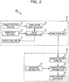
- FIG. 2 is a block diagram of functions achieved by execution of the image capture program and the biometric authentication program.
- the execution of the image capture program achieves an image capture device 10 and an authentication device 20 in the biometric authentication apparatus 100.
- the image capture device 10 functions as an instructing unit 11 configured to provide an instruction, a fingertip location detector 12 configured to detect a location of a fingertip, an image capture height calculator 13 configured to calculate a height in image capture, a palm height detector 14 configured to detect the height of a palm, a height determining unit 15 configured to determine a height, and an image capture unit 16 configured to capture an image.
- the authentication device 20 functions as a biometric feature extractor 21 configured to extract a biometric feature, a biometric feature comparing unit 22 configured to perform comparing, a registered feature data storage unit 23 configured to store the registered feature data, and an authentication result outputting unit 24 configured to output a result of authentication.
- the mounting angle (optical axis) of the image sensor 105 is described.
- an image is captured in an attitude in which a fingertip is in contact with the surface 201 and the palm is raised. That is, the palm is held obliquely to the surface 201.
- the image sensor 105 may preferably be mounted such that its optical axis is orthogonal to the palm.
- the palm may preferably be positioned within the sensor field of view of the image sensor 105. Examples of those conditions will be described below.
- the distance from a fingertip to the center of the sensor surface of the image sensor 105 (center of the optical axis) on the surface 201 is defined as distance d
- the distance from the sensor surface of the image sensor 105 to the palm is defined as height h
- the length of the palm is defined as 2a.
- One example of the length of the palm may be the distance from the base of the hand to the base of the middle finger.
- the length of the finger being in contact with the surface 201 is defined as b.
- One example of b may be the length of the middle finger.
- the sum of "a" and b is defined as c.
- c indicates the distance from the fingertip being in contact with the surface 201 to the center of the palm.
- the angle of view of the optical axis of the image sensor 105 is defined as 2 ⁇ .
- the angle between the surface 201 and the optical axis of the image sensor 105 is defined as angle ⁇ .
- the angle ⁇ may preferably satisfy the following Expression (1).
- ⁇ tan ⁇ 1 a + b / h
- the image sensor 105 may preferably be arranged such that the angle ⁇ satisfies the above Expression (3).
- the palm length 2a may preferably be designed so as to suit expected users. For example, according to Anthropometric Database 1991-92 in National Institute of Advanced Industrial Science and Technology (AIST) (http://riodb.ibase.aist.go.jp/dhbodydb/91-92/), about the palm length (Item L2), the average value for adult males is 11.3 cm and that for elderly people is 11 cm. For example, when the sensor angle of view 2 ⁇ is 80°, the palm size 2a is 11 cm, and the finger length b is 8 cm, the angle ⁇ is 66°. In actuality, if ⁇ is strictly set, the apparatus is susceptible to positional displacement.
- an index point set on the surface 201 is described.
- the location of a fingertip when the palm is placed on the image sensor 105 with reference to an index point in the vicinity of the image sensor 105 is detected, and when the palm is isolated upward while the fingertip remains on the surface 201 and the palm is raised up to a proper distance, an image is captured.
- the index point may preferably be easy to identify for them.
- One example of the index point may be the center of the palm. In actual use, the center of the palm may not be used as the index point. For example, the base of the thumb or the like may also be used.
- the index point is determined as a relative location to the center of the palm, and it may be indicated on the surface 201 by marking or the like. If a location significantly remote from the center is selected, an error in detection is large. Thus the center of the palm may be preferable as the index point.
- the state where the surface of the palm is orthogonal to the optical axis of the image sensor 105 may be preferable for a proper image taking location.
- the location of the center of the palm when the palm pivots about the fingertip point B being in contact with the surface 201 such that the palm comes into contact with the surface 201 is defined as an index point A.
- Indicating the index point A on the surface 201 facilitates operations. If the index point A is sufficiently near the sensor center and the sensor field of view is set with a margin, the image sensor 105 itself may be used in place of the mark.
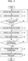
- FIG. 4 is an illustration for describing an example flowchart of a process performed by the biometric authentication apparatus 100.
- steps S1 to S8 indicate the image capture processing performed by the image capture device 10
- step S9 indicates the biometric authentication processing performed by the authentication device 20.
- the instructing unit 11 instructs a user to place his or her hand on the surface 201 using the index point A as a marker (step S1). Specifically, the instructing unit 11 displays a message to the user on the display device 104. When the center of the palm is used as the index point A, the instructing unit 11 instructs the user to place his or her hand on the surface 201 with the target of coincidence between the index point A and the center of the palm.
- the fingertip location detector 12 detects the location of the fingertip (step S2). Then, the fingertip location detector 12 determines whether the detection of the fingertip has succeeded (step S3). When "No" is determined in step S3, the processing from step S1 is performed again.
- the fingertip location detector 12 determines the location of the fingertip in accordance with the depressed key in the input equipment 106. Because the size of one key is approximately 1 cm, an error of approximately ⁇ 1 cm may occur. If two depressed keys are detected, the midpoint between the two keys can be determined to be the location of the fingertip, and an error is approximately ⁇ 0.5 cm. That degree of error is not so large in using the biometric authentication apparatus 100.
- the location of the fingertip can be detected more easily.
- a touch panel is used as the input equipment 106, the location with which the fingertip is in contact can be detected accurately.
- the image sensor 105 can be implemented below the screen.
- a dedicated sensor can be used to detect the location of the fingertip. The dedicated sensor is optional.
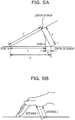
- FIG. 5A is an illustration for describing an example of the optimal height of the palm.
- the optimal height h is determined in accordance with the angle of view 2 ⁇ of the image sensor 105, as previously described. In the present embodiment, it is determined from the fingertip location point B.
- a triangle formed among the fingertip location point B, the sensor center of the image sensor 105, and the center of the palm is a right-angled triangle. Accordingly, the following relationship is established.
- h ⁇ d 2 ⁇ c 2
- the instructing unit 11 instructs the user to raise the palm while the fingertip remains on the surface 201 (step S5). Specifically, the instructing unit 11 displays a message to the user on the display device 104. Then, the palm height detector 14 detects the height h of the palm (step S6).
- Various techniques can be used as a method of determining the height h of the palm using the image sensor 105.
- One example technique is the one of emitting spot light parallel with or substantially parallel with the optical axis of the image sensor 105 to a subject and determining the height h of the palm based on a location of the spot light in an obtained image (for example, Japanese Patent No. 4644540 ).
- the height determining unit 15 determines whether the height h of the palm detected in step S6 is within an appropriate range (step S7).
- the appropriate range can be set at a certain range including the optimal height h represented by the above Expression (5).
- the appropriate range can be set at a range whose center is the optimal height h.
- the authentication device 20 performs the biometric authentication processing (step S9) using the image acquired in step S8.
- the biometric feature extractor 21 extracts a biometric feature from the image.
- the biometric feature comparing unit 22 calculates the degree of similarity between the registered feature data registered in the registered feature data storage unit 23 and the biometric feature extracted by the biometric feature extractor 21.
- the biometric feature comparing unit 22 determines that the checking is successful.
- the result of the checking by the biometric feature comparing unit 22 is output to the display device 104 by the authentication result outputting unit 24.
- the location of the palm to the front, rear, right, and left is stable.
- the palm is isolated upward while the fingertip is in contact with the surface 201, the height of the palm is stable.
- the inclination in horizontal directions is easily visible and thus can be easily stabilized originally. It can be expected that this inclination is further stabilized by placement of the fingertip.
- the accuracy it can be expected that the stable attitude leads to high reproducibility in acquired images and to a reduced false rejection rate.
- advantages for the speed (processing time) are also obtainable. It can be expected that the stable attitude allows processing for correcting the attitude to be omitted and thus leads to a reduced calculation time desired for authentication processing. Because finding the location is clear and an operation method is simple, one of the most promising advantages is a reduction in the time desired for operation by a user.
- the operation may take several tens of seconds because he or she gradually makes the attitude effective by trial and error.
- the technique of the present embodiment the user has only to place his or her hand and then raise the palm, so that image capture is completed in several seconds.
- the height determining unit 15 may detect the attitude of a subject in accordance with measurement of the distances between the surface of the palm and the sensor surface of the image sensor 105 at a plurality of sites. For example, as illustrated in FIG. 5B , a state where the palm is raised while being bent can be detected. In the present embodiment, it may be preferable that an image be captured in a state where the fingertip is in contact with the surface 201 and the palm extends. However, depending on the user, the palm may be raised while the hand is bent. In that case, the instructing unit 11 may output an alert using the display device 104 or the like when a detected attitude does not meet a certain condition.
- the instructing unit 11 may display an alert that indicates the possibility of bending on the display device 104 and may prompt the user to stretch his or her palm.
- the fingertip location point B can be determined by placement of the user's hand with reference to the index point A.
- the index point A in FIG. 5A is in the location by the distance c from the fingertip location point B, and its optimal location is dependent on the size of the hand.
- design may preferably be based on a standard hand size.
- the average size of the palm for adults is 11.3 cm
- the average length of the middle finger is 7.96 cm (according to the above-mentioned Anthropometric Database in AIST).
- the index point A where the hand has to be initially placed, varies with the size of the hand.
- the center of the palm when the center of the palm is placed on the index point A and the palm is raised such that the fingertip location point B acts as a pivot, the center of the palm coincides with the center of the optical axis of the image sensor 105 at a certain height.
- the index point determined from the standard size is used as a representative value, as described in the above Expression (2), in the case of the person with small hands, the fingertip is placed in a location displaced from B' toward B by the length between A and A'. Accordingly, an image is captured in a location slightly higher than the optimal location.
- the distance e between the sensor center O of the image sensor 105 and the index point A meets the relationship of the following Expression (6), where the distance between the index point A and the fingertip location point B is c. That is, the distance between the index point A and the sensor center O of the image sensor 105 reduces with a reduction in the height h, that is, with an increase in the angle of view ⁇ .
- e ⁇ c 2 ⁇ h 2 ⁇ c
- the fingertip is in contact with the surface 201, and the palm is raised such that the point of contact acts as a pivot.
- the base of the palm may be in contact with the surface 201, and the fingers and the palm may be raised such that the point of contact acts as a pivot.
- the way of having the contact between any location of the palm and the surface 201 and raising other portions of the palm such that the point of contact acts as a pivot can stabilize the attitude of the palm.
- the mounting angle of the image sensor 105 may preferably be set so as to be substantially orthogonal to the inclination of the palm even if any location is used as the point of contact.
- the palm is used as a subject for capturing an image in a noncontact manner.
- another portion such as a face
- a request for the location of a subject to a user is displayed on the display device 104.
- Other informing media such as sound, may also be used.
- step S5 only an instruction to raise the palm is provided to a user. Instructions to the user to lower the palm if the detected height h is large and to raise the palm if the detected height h is small may be provided.
- the image capture device 10 and the authentication device 20 in the above-described examples may be configured as dedicated circuits or the like.
- the fingertip location detector 12 functions as a detector configured to detect a location where a surface of a casing and a subject are in contact with each other.
- the height determining unit 15 functions as an image capture controller configured to perform control such that an image is captured when a distance between the subject and a sensor meets a certain criterion and functions as an attitude detector configured to detect an attitude of the subject by detecting the distances between the surface of the casing and the subject at a plurality of sites.
- the instructing unit 11 functions as an outputting unit configured to output an alert when the attitude detected by the attitude detector does not meet the certain condition.
Description
- The technique discussed in the embodiment is related to a biometric authentication apparatus and a biometric authentication method.
-
PLT -
- PTL 1: Japanese Laid-open Patent Publication No.
2007-233981 - PTL 2: Japanese Laid-open Patent Publication No.
2012-208687 - Biometric information input in biometric authentication includes fluctuations resulting from a state at the time of input (e.g., a way in which a hand is held). The fluctuations are a cause of a reduction in authentication accuracy.
- It is an object of the technique discussed in the embodiment to suppress a reduction in authentication accuracy in biometric authentication.
- The present invention provides a biometric authentication apparatus including a casing and an image sensor to capture images in a region above a surface of the casing according to
Claim 1.
The present invention also provides a biometric authentication method executed by a computer including a casing and an image sensor to capture images in a region above a surface of the casing according to Claim 8. - The technique discussed in the embodiment can suppress a reduction in authentication accuracy in biometric authentication.
-
-
FIG. 1A is a block diagram for describing hardware configuration in a biometric authentication apparatus according toEmbodiment 1, andFIG. 1B illustrates an example apparatus in which the biometric authentication apparatus is incorporated. -
FIG. 2 is a block diagram of functions achieved by execution of an image capture program and a biometric authentication program. -
FIGs. 3A and 3B are illustrations for describing a height of a palm. -
FIG. 4 is an illustration for describing an example flowchart of a process performed by the biometric authentication apparatus. -
FIG. 5A is an illustration for describing a height of a palm, andFIG. 5B is an illustration for describing bending of the palm. -
FIGs. 6A and 6B are illustrations for describing an index point. - An embodiment is described below with reference to the drawings.
-
FIG. 1A is a block diagram for describing hardware configuration in abiometric authentication apparatus 100 according toEmbodiment 1. Referring toFIG. 1A , thebiometric authentication apparatus 100 includes a central processing unit (CPU) 101, a random-access memory (RAM) 102, astorage device 103, adisplay device 104, animage sensor 105,input equipment 106, and the like. - The
CPU 101 is a central processing unit. TheCPU 101 includes one or more cores. TheRAM 102 is volatile memory for temporarily storing a program to be executed by theCPU 101, data to be processed by theCPU 101, and the like. Thestorage device 103 is nonvolatile memory. Examples usable as thestorage device 103 can include a read-only memory (ROM), a solid-state drive, such as flash memory, and a hard disk driven by a hard disk drive. Thestorage device 103 stores an image capture program and a biometric authentication program. - Examples of the
display device 104 can include a liquid crystal display and an electroluminescent panel. Thedisplay device 104 can display instructions to a user, results of image capture processing and biometric authentication processing, which are described below, and the like. Theimage sensor 105 may be any device capable of acquiring a biometric image by capturing an image of a subject in a noncontact manner and is not particularly limited. One example of theimage sensor 105 may be a complementary metal-oxide semiconductor (CMOS) camera. In the present embodiment, theimage sensor 105 acquires an image of a palm of a user as one example. Theinput equipment 106 may be equipment, such as a keyboard or a touch panel. -
FIG. 1B illustrates an example apparatus in which thebiometric authentication apparatus 100 is incorporated. Thebiometric authentication apparatus 100 can be incorporated in aterminal 200 as one example. One example of theterminal 200 may be mobile equipment, such as a notebook personal computer or a tablet terminal. Referring toFIG. 1B , theimage sensor 105 is provided to a surface of a casing of theterminal 200. Theimage sensor 105 can be provided to asurface 201 of theterminal 200 in which theinput equipment 106, such as a keyboard or a touch panel, is disposed. A mounting angle (optical axis) of theimage sensor 105 is set obliquely to thesurface 201. - The image capture program and the biometric authentication program stored in the
storage device 103 is developed in theRAM 102 such that they are executable. TheCPU 101 executes the image capture program and the biometric authentication program developed in theRAM 102. The execution performs the image capture processing and the biometric authentication processing in thebiometric authentication apparatus 100. The image capture processing is processing of acquiring a biometric image by capturing an image of a subject. The biometric authentication processing is processing of identifying an authorized user by checking feature data for use in checking obtained in authentication against registered feature data, which was registered in advance. -
FIG. 2 is a block diagram of functions achieved by execution of the image capture program and the biometric authentication program. The execution of the image capture program achieves animage capture device 10 and anauthentication device 20 in thebiometric authentication apparatus 100. Theimage capture device 10 functions as an instructingunit 11 configured to provide an instruction, afingertip location detector 12 configured to detect a location of a fingertip, an imagecapture height calculator 13 configured to calculate a height in image capture, apalm height detector 14 configured to detect the height of a palm, aheight determining unit 15 configured to determine a height, and animage capture unit 16 configured to capture an image. Theauthentication device 20 functions as abiometric feature extractor 21 configured to extract a biometric feature, a biometricfeature comparing unit 22 configured to perform comparing, a registered featuredata storage unit 23 configured to store the registered feature data, and an authenticationresult outputting unit 24 configured to output a result of authentication. - Next, a preferred value of the mounting angle (optical axis) of the
image sensor 105 is described. In the present embodiment, an image is captured in an attitude in which a fingertip is in contact with thesurface 201 and the palm is raised. That is, the palm is held obliquely to thesurface 201. Thus theimage sensor 105 may preferably be mounted such that its optical axis is orthogonal to the palm. At that time, the palm may preferably be positioned within the sensor field of view of theimage sensor 105. Examples of those conditions will be described below. - Referring to
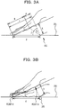
FIG. 3A , the distance from a fingertip to the center of the sensor surface of the image sensor 105 (center of the optical axis) on thesurface 201 is defined as distance d, the distance from the sensor surface of theimage sensor 105 to the palm is defined as height h, and the length of the palm is defined as 2a. One example of the length of the palm may be the distance from the base of the hand to the base of the middle finger. The length of the finger being in contact with thesurface 201 is defined as b. One example of b may be the length of the middle finger. The sum of "a" and b is defined as c. Because "a" indicates one-half of the length of the palm, c indicates the distance from the fingertip being in contact with thesurface 201 to the center of the palm. The angle of view of the optical axis of theimage sensor 105 is defined as 2α. The angle between thesurface 201 and the optical axis of theimage sensor 105 is defined as angle β. - To position the palm within the sensor field of view, the angle β may preferably satisfy the following Expression (1).

- When in Expression (1) the height h is a height at which an image can be taken using the
image sensor 105 with the angle of view, 2α, such that the palm length 2a is within the sensor field of view, the following Expression (2) is established.
- When the above Expression (2) is substituted into the above Expression (1), the angle β can be determined from the following Expression (3).

- The
image sensor 105 may preferably be arranged such that the angle β satisfies the above Expression (3). - The palm length 2a may preferably be designed so as to suit expected users. For example, according to Anthropometric Database 1991-92 in National Institute of Advanced Industrial Science and Technology (AIST) (http://riodb.ibase.aist.go.jp/dhbodydb/91-92/), about the palm length (Item L2), the average value for adult males is 11.3 cm and that for elderly people is 11 cm. For example, when the sensor angle of view 2α is 80°, the palm size 2a is 11 cm, and the finger length b is 8 cm, the angle β is 66°. In actuality, if α is strictly set, the apparatus is susceptible to positional displacement. Thus adjustment for setting a height at which an image in a range slightly larger than the palm size 2a can be taken may preferably be carried out. For example, when a margin of 1 cm is set, the angle β may be determined by applying a' = a + 1 and b' = b - 1 to the above Expression (3).
- Next, an index point set on the
surface 201 is described. In the present embodiment, the location of a fingertip when the palm is placed on theimage sensor 105 with reference to an index point in the vicinity of theimage sensor 105 is detected, and when the palm is isolated upward while the fingertip remains on thesurface 201 and the palm is raised up to a proper distance, an image is captured. Because users hold their palms relative to the index point, the index point may preferably be easy to identify for them. One example of the index point may be the center of the palm. In actual use, the center of the palm may not be used as the index point. For example, the base of the thumb or the like may also be used. In that case, the index point is determined as a relative location to the center of the palm, and it may be indicated on thesurface 201 by marking or the like. If a location significantly remote from the center is selected, an error in detection is large. Thus the center of the palm may be preferable as the index point. - As in
FIG. 3B , the state where the surface of the palm is orthogonal to the optical axis of theimage sensor 105 may be preferable for a proper image taking location. In that case, it may be preferable that the palm is properly positioned within the field of view of theimage sensor 105. That is, it may be preferable that the center of the optical axis of theimage sensor 105 and the center of the palm coincide with each other. The location of the center of the palm when the palm pivots about the fingertip point B being in contact with thesurface 201 such that the palm comes into contact with thesurface 201 is defined as an index point A. Indicating the index point A on the surface 201 (displaying it on a screen, inscribing or printing it on a casing, and the like) facilitates operations. If the index point A is sufficiently near the sensor center and the sensor field of view is set with a margin, theimage sensor 105 itself may be used in place of the mark. - Next, actions of the
biometric authentication apparatus 100 are described.FIG. 4 is an illustration for describing an example flowchart of a process performed by thebiometric authentication apparatus 100. In the flowchart inFIG. 4 , steps S1 to S8 indicate the image capture processing performed by theimage capture device 10, and step S9 indicates the biometric authentication processing performed by theauthentication device 20. Referring toFIGs. 2 and4 , the instructingunit 11 instructs a user to place his or her hand on thesurface 201 using the index point A as a marker (step S1). Specifically, the instructingunit 11 displays a message to the user on thedisplay device 104. When the center of the palm is used as the index point A, the instructingunit 11 instructs the user to place his or her hand on thesurface 201 with the target of coincidence between the index point A and the center of the palm. - Then, the
fingertip location detector 12 detects the location of the fingertip (step S2). Then, thefingertip location detector 12 determines whether the detection of the fingertip has succeeded (step S3). When "No" is determined in step S3, the processing from step S1 is performed again. Referring toFIG. 1B again, when theimage sensor 105 is incorporated in a palm rest portion of the terminal 200, for example, the fingertip comes into contact with the keyboard. When the palm is raised such that the fingertip acts as a pivot, the finger naturally depresses a specific key. Thefingertip location detector 12 determines the location of the fingertip in accordance with the depressed key in theinput equipment 106. Because the size of one key is approximately 1 cm, an error of approximately ±1 cm may occur. If two depressed keys are detected, the midpoint between the two keys can be determined to be the location of the fingertip, and an error is approximately ±0.5 cm. That degree of error is not so large in using thebiometric authentication apparatus 100. - When the terminal 200 is a tablet terminal, the location of the fingertip can be detected more easily. In that case, because a touch panel is used as the
input equipment 106, the location with which the fingertip is in contact can be detected accurately. In that case, theimage sensor 105 can be implemented below the screen. As described above, a dedicated sensor can be used to detect the location of the fingertip. The dedicated sensor is optional. - Referring to
FIGs. 2 and4 again, when "Yes" is determined in step S3, the imagecapture height calculator 13 calculates an optimal height of the palm (step S4).FIG. 5A is an illustration for describing an example of the optimal height of the palm. The optimal height h is determined in accordance with the angle of view 2α of theimage sensor 105, as previously described. In the present embodiment, it is determined from the fingertip location point B. When the palm is held at the optimal height h, as illustrated inFIG. 5A , a triangle formed among the fingertip location point B, the sensor center of theimage sensor 105, and the center of the palm is a right-angled triangle. Accordingly, the following relationship is established.
surface 201, the distance e is also a fixed value. Accordingly, the optimal height h can be represented as the following Expression (5).
- Referring to
FIGs. 2 and4 again, after step S4, the instructingunit 11 instructs the user to raise the palm while the fingertip remains on the surface 201 (step S5). Specifically, the instructingunit 11 displays a message to the user on thedisplay device 104. Then, thepalm height detector 14 detects the height h of the palm (step S6). Various techniques can be used as a method of determining the height h of the palm using theimage sensor 105. One example technique is the one of emitting spot light parallel with or substantially parallel with the optical axis of theimage sensor 105 to a subject and determining the height h of the palm based on a location of the spot light in an obtained image (for example, Japanese Patent No.4644540 - Then, the
height determining unit 15 determines whether the height h of the palm detected in step S6 is within an appropriate range (step S7). The appropriate range can be set at a certain range including the optimal height h represented by the above Expression (5). For example, the appropriate range can be set at a range whose center is the optimal height h. When "No" is determined in step S7, the processing from step S5 is performed again. When "Yes" is determined in step S7, theimage capture unit 16 instructs theimage sensor 105 to capture an image and acquires the image (step S8). - Then, the
authentication device 20 performs the biometric authentication processing (step S9) using the image acquired in step S8. Specifically, thebiometric feature extractor 21 extracts a biometric feature from the image. When the palm is used as the subject, veins in the palm, a palm print, an outline, and the like can be used as the biometric feature. Then, the biometricfeature comparing unit 22 calculates the degree of similarity between the registered feature data registered in the registered featuredata storage unit 23 and the biometric feature extracted by thebiometric feature extractor 21. When the degree of similarity is at or above a threshold value, the biometricfeature comparing unit 22 determines that the checking is successful. The result of the checking by the biometricfeature comparing unit 22 is output to thedisplay device 104 by the authenticationresult outputting unit 24. When the above processing is completed, the execution of the process of the flowchart ends. - According to the present embodiment, because the fingertip is in contact with the
surface 201, the location of the palm to the front, rear, right, and left is stable. In addition, because the palm is isolated upward while the fingertip is in contact with thesurface 201, the height of the palm is stable. - Because an image is captured when the distance between the subject and the
image sensor 105 meets a criterion established based on the distance between the location of the fingertip and theimage sensor 105 and the distance between the index point A and theimage sensor 105, the inclination of the palm is stable. Consequently, the reproducibility in inputting biometric information can be improved. This can suppress a reduction in authentication accuracy. - The inclination in horizontal directions is easily visible and thus can be easily stabilized originally. It can be expected that this inclination is further stabilized by placement of the fingertip. As for the accuracy, it can be expected that the stable attitude leads to high reproducibility in acquired images and to a reduced false rejection rate. In addition, it can be expected that advantages for the speed (processing time) are also obtainable. It can be expected that the stable attitude allows processing for correcting the attitude to be omitted and thus leads to a reduced calculation time desired for authentication processing. Because finding the location is clear and an operation method is simple, one of the most promising advantages is a reduction in the time desired for operation by a user. If an unaccustomed user operates the apparatus in accordance with instructions, the operation may take several tens of seconds because he or she gradually makes the attitude effective by trial and error. In contrast, when the technique of the present embodiment is used, the user has only to place his or her hand and then raise the palm, so that image capture is completed in several seconds.
- The
height determining unit 15 may detect the attitude of a subject in accordance with measurement of the distances between the surface of the palm and the sensor surface of theimage sensor 105 at a plurality of sites. For example, as illustrated inFIG. 5B , a state where the palm is raised while being bent can be detected. In the present embodiment, it may be preferable that an image be captured in a state where the fingertip is in contact with thesurface 201 and the palm extends. However, depending on the user, the palm may be raised while the hand is bent. In that case, the instructingunit 11 may output an alert using thedisplay device 104 or the like when a detected attitude does not meet a certain condition. For example, when theheight determining unit 15 determines that the difference between two or more detected distances is at or above a threshold value, the instructingunit 11 may display an alert that indicates the possibility of bending on thedisplay device 104 and may prompt the user to stretch his or her palm. - As described above, in the present embodiment, the fingertip location point B can be determined by placement of the user's hand with reference to the index point A. The index point A in
FIG. 5A is in the location by the distance c from the fingertip location point B, and its optimal location is dependent on the size of the hand. Thus, design may preferably be based on a standard hand size. The average size of the palm for adults is 11.3 cm, and the average length of the middle finger is 7.96 cm (according to the above-mentioned Anthropometric Database in AIST). Thus, the average length c from the center of the palm to the fingertip is 11.3 / 2 + 7.96 = 13.61 cm. As discussed in the above Expression (1), when the mounting angle of theimage sensor 105 is 66°, the distance d is 14.9 cm, and thus e is 1.3 cm. A case where this setting condition is used in persons having different hand sizes is discussed below. Because the center of the palm is placed in the same location, the location of the fingertip shifts toward the sensor, and the hand is held in a manner indicated by the broken lines inFIG. 6A . - In the discussion up to here, it is intended that the center of the palm when the hand is held coincide with the center of the optical axis.
- However, as illustrated in
FIG. 6B , the index point A, where the hand has to be initially placed, varies with the size of the hand. In the case of a standard hand size, when the center of the palm is placed on the index point A and the palm is raised such that the fingertip location point B acts as a pivot, the center of the palm coincides with the center of the optical axis of theimage sensor 105 at a certain height. However, in the case of a person with small hands, to make the center of the palm coincide with the center of the optical axis, it may be preferable that his or her hand be initially placed on a point A'. However, it is impossible to determine an optimal index point (location of the marker) if the size of the hand of the user is not known in advance. Thus, because the index point determined from the standard size is used as a representative value, as described in the above Expression (2), in the case of the person with small hands, the fingertip is placed in a location displaced from B' toward B by the length between A and A'. Accordingly, an image is captured in a location slightly higher than the optimal location. - The distance e between the sensor center O of the
image sensor 105 and the index point A meets the relationship of the following Expression (6), where the distance between the index point A and the fingertip location point B is c. That is, the distance between the index point A and the sensor center O of theimage sensor 105 reduces with a reduction in the height h, that is, with an increase in the angle of view α.
- In the case where hands with different sizes are used, when the distance c' between B' and C' is k × c, the distance e' between O and A' is k × e, and thus the difference Δ between A and A' is (1 - k) × e. As calculated above, when the average hand size for adult males is used as the standard, e is 1.3 cm. The minimum value of the palm length for adults (females) is 8.7 cm and that of the finger length is 6.2 cm. Thus, c = 8.7 / 2 + 6.2 = 10.55 cm. From k = 0.78, Δ = 0.29 cm. Hence, the finger is placed in a location displaced toward the fingertip location point B by 0.29 cm. This is no more than 3 mm, can fall within the range of variation occurring in placement of the hand, and thus causes no problem.
- Image capture is discussed below for a better understanding. The field of view shifts by Δ × sinβ and an image is taken in a location higher by Δ × sinβ. Thus, if there is no margin, the region on the finger side of the palm may lack by Δ(sinβ - sinα). In the case of an example design in the above Expression (1), because α is 40° and β is 66°, the range of the lack is 0.078 cm, which is no more than 1 mm, and the effects are very small. Therefore, if there is a margin in the field of view, no problem arises. In contrast, in the case of a large hand, the maximum value of the palm size (for males) is 13.1 cm, that of the finger length is 9 cm, c = 13.1 / 2 + 9 = 15.55 cm. From k = 1.14, Δ = 0.18 cm. Thus, the hand is placed in a location remote from the point B by 0.18 cm. This difference is on the order of 2 mm, and the effects are smaller than those in the previous discussion, and there is no problem.
- In the above-described examples, the fingertip is in contact with the
surface 201, and the palm is raised such that the point of contact acts as a pivot. However, in a background example, the base of the palm may be in contact with thesurface 201, and the fingers and the palm may be raised such that the point of contact acts as a pivot. The way of having the contact between any location of the palm and thesurface 201 and raising other portions of the palm such that the point of contact acts as a pivot can stabilize the attitude of the palm. In that case, the mounting angle of theimage sensor 105 may preferably be set so as to be substantially orthogonal to the inclination of the palm even if any location is used as the point of contact. - In the above-described examples, the palm is used as a subject for capturing an image in a noncontact manner. However, in a background example, another portion, such as a face, may be targeted. In the above-described examples, a request for the location of a subject to a user is displayed on the
display device 104. Other informing media, such as sound, may also be used. In the example illustrated inFIG. 4 , in step S5, only an instruction to raise the palm is provided to a user. Instructions to the user to lower the palm if the detected height h is large and to raise the palm if the detected height h is small may be provided. Theimage capture device 10 and theauthentication device 20 in the above-described examples may be configured as dedicated circuits or the like. - In the above-described examples, the
fingertip location detector 12 functions as a detector configured to detect a location where a surface of a casing and a subject are in contact with each other. Theheight determining unit 15 functions as an image capture controller configured to perform control such that an image is captured when a distance between the subject and a sensor meets a certain criterion and functions as an attitude detector configured to detect an attitude of the subject by detecting the distances between the surface of the casing and the subject at a plurality of sites. The instructingunit 11 functions as an outputting unit configured to output an alert when the attitude detected by the attitude detector does not meet the certain condition. - The embodiment of the present disclosure is described above. The present disclosure is not limited to a particular embodiment, and various modifications and changes may be made within the scope of the disclosure as defined in the claims.
-
- 10
- image pickup device
- 11
- instructing unit
- 12
- fingertip location detector
- 13
- image pickup height calculator
- 14
- palm height detector
- 15
- height determining unit
- 16
- image pickup unit
- 20
- authentication device
- 21
- biometric feature extractor
- 22
- biometric feature checking unit
- 23
- registered feature data storage unit
- 24
- authentication result outputting unit
- 100
- biometric authentication apparatus
- 105
- image sensor
- 106
- input equipment
- 200
- terminal
- 201
- surface
Claims (11)
- A biometric authentication apparatus (100) including a casing (200) and an image sensor (105) to capture images in a region above a surface (201) of the casing (200), the biometric authentication apparatus (100) comprising:a location detector (12) configured to detect a contact location on the surface (201) at which a fingertip of a hand of a user is in contact with the surface (201);a height calculator (13) configured to determine an optimal height (h) of the palm being an optimal distance between the palm and the image sensor (105), based on a calculated first distance (d) between the contact location and the image sensor (105), and a second distance (c) between the fingertip and a center of the palm;a height detector (14) configured to detect the height of the palm when the palm is raised while the fingertip remains in contact with the surface (201);a height determining unit (15) configured to determine whether the height detected by the height detector (14) is within a range including the determined optimal height (h); andan image capture controller (16) configured to cause the image sensor (105) to perform image capture processing when the height of the palm detected by the height detector (14) is determined to be within the range.
- The biometric authentication apparatus (100) according to claim 1, further comprising:
an instructing unit (11) configured to output an instruction to the user to place the hand on the surface (201) such that a mark provided on the surface (201) coincides with a center of the palm of the hand. - The biometric authentication apparatus (100) according to claim 1 or 2, wherein the image sensor (105) is embedded in the casing (200) and has an optical axis extending in a direction inclined to the surface (201).
- The biometric authentication apparatus (100) according to any one of claims 1 to 3, wherein:the height determining unit (15) is configured to calculate a plurality of distances between the surface (201) and each of a plurality of points on the palm based on an image acquired by the image sensor (105), and to detect an attitude of the hand based on the plurality of distances; andthe biometric authentication apparatus (100) further comprises an outputting unit (11) configured to output an alert when the detected attitude does not meet a certain condition.
- The biometric authentication apparatus (100) according to any one of Claims 1 to 4, further comprising:
an authenticating unit (20) configured to perform authentication using biometric information extracted from data of a first image captured by the image capture processing. - The biometric authentication apparatus (100) according to claim 5, further comprising:a keyboard disposed in the surface (201),wherein the location detector (12) is configured to detect the location where the surface (201) and the fingertip are in contact with each other based on a location of a depressed key in the keyboard.
- The biometric authentication apparatus (100) according to claim 5, further comprising:a touch panel disposed in the surface (201),wherein the location detector (12) is configured to detect the location where the surface (201) and the fingertip are in contact with each other based on a location where the fingertip is in contact with the touch panel.
- A biometric authentication method executed by a computer including a casing (200) and an image sensor (105) to capture images in a region above a surface (201) of the casing (200), the biometric authentication method comprising:detecting (S2) a contact location on the surface (201) at which a fingertip of a hand of a user is in contact with the surface (201);determining an optimal height (h) of the palm being an optimal distance between the palm and the image sensor (105), based on a calculated first distance (d) between the contact location and the image sensor (105), and a second distance (c) between the fingertip and a center of the palm;detecting the height of the palm when the palm is raised while the fingertip remains in contact with the surface (201);determining whether the detected height is within a range including the determined optimal height (h); andcausing (S8) the image sensor to perform image capture processing when the detected height is within the range.
- The biometric authentication method according to claim 8, further comprising:
outputting (S1) an instruction to the user to place the hand on the surface (201) such that an index point (A) on the surface (201) coincides with a center of the palm of the hand. - The biometric authentication method according to claim 8 or 9, wherein the image sensor (105) is embedded in the casing, and has an optical axis extending in a direction inclined to the surface (201).
- The biometric authentication method according to any one of claims 8 to 10, wherein:a plurality of distances between the surface (201) and each of a plurality of points on the palm are calculated, based on an image acquired by the image sensor (105); andthe biometric authentication method further comprises:detecting (S6) an attitude of the hand based on the plurality of distances; andoutputting (S5) an alert when the detected attitude does not meet a certain condition.
Applications Claiming Priority (1)
| Application Number | Priority Date | Filing Date | Title |
|---|---|---|---|
| JP2013154839A JP6111921B2 (en) | 2013-07-25 | 2013-07-25 | Imaging apparatus and imaging method |
Publications (3)
| Publication Number | Publication Date |
|---|---|
| EP2830002A2 EP2830002A2 (en) | 2015-01-28 |
| EP2830002A3 EP2830002A3 (en) | 2015-06-24 |
| EP2830002B1 true EP2830002B1 (en) | 2020-10-07 |
Family
ID=51162473
Family Applications (1)
| Application Number | Title | Priority Date | Filing Date |
|---|---|---|---|
| EP14175200.6A Active EP2830002B1 (en) | 2013-07-25 | 2014-07-01 | Image capture device, biometric authentication apparatus, and image capture method |
Country Status (3)
| Country | Link |
|---|---|
| US (1) | US10171717B2 (en) |
| EP (1) | EP2830002B1 (en) |
| JP (1) | JP6111921B2 (en) |
Cited By (1)
| Publication number | Priority date | Publication date | Assignee | Title |
|---|---|---|---|---|
| EP3518144B1 (en) * | 2018-01-30 | 2023-11-08 | Fujitsu Limited | Biometric authentication apparatus and biometric authentication method |
Families Citing this family (9)
| Publication number | Priority date | Publication date | Assignee | Title |
|---|---|---|---|---|
| JP6241230B2 (en) * | 2013-11-28 | 2017-12-06 | 富士通株式会社 | Biological information determination apparatus and program |
| US20180041926A1 (en) | 2015-02-13 | 2018-02-08 | Nec Corporation | Apparatus, system and method for security management |
| JP6589309B2 (en) * | 2015-03-16 | 2019-10-16 | 富士通株式会社 | Terminal device, biometric authentication program, and biometric authentication method |
| JP6657593B2 (en) * | 2015-05-08 | 2020-03-04 | 富士通株式会社 | Biological imaging apparatus, biological imaging method, and biological imaging program |
| JP6679897B2 (en) * | 2015-11-20 | 2020-04-15 | 富士通株式会社 | Information processing device, biometric authentication method, and biometric authentication program |
| US10963159B2 (en) * | 2016-01-26 | 2021-03-30 | Lenovo (Singapore) Pte. Ltd. | Virtual interface offset |
| JP6583025B2 (en) | 2016-02-01 | 2019-10-02 | 富士通株式会社 | Biological information processing apparatus, biological information processing method, biological information processing program, and distance detection apparatus |
| JP6878826B2 (en) * | 2016-10-20 | 2021-06-02 | 富士通株式会社 | Shooting device |
| CN112888443A (en) * | 2018-08-01 | 2021-06-01 | 爱迪克斯-欧有限公司 | Injectable composition with prolonged duration of action for its use in the treatment of nail diseases and/or for accelerating nail growth |
Family Cites Families (20)
| Publication number | Priority date | Publication date | Assignee | Title |
|---|---|---|---|---|
| JP3663075B2 (en) * | 1999-04-05 | 2005-06-22 | シャープ株式会社 | Information processing device |
| JP2003187235A (en) * | 2001-12-18 | 2003-07-04 | Hitachi Software Eng Co Ltd | Finger vein recognition device |
| US8190239B2 (en) * | 2002-09-03 | 2012-05-29 | Fujitsu Limited | Individual identification device |
| JP4015153B2 (en) | 2003-03-18 | 2007-11-28 | 富士通株式会社 | Imaging device |
| JP4515850B2 (en) | 2004-07-30 | 2010-08-04 | 富士通株式会社 | Biometric device guidance screen control method, biometric device and program thereof |
| JP4546169B2 (en) | 2004-06-28 | 2010-09-15 | 富士通株式会社 | An imaging device for palm authentication |
| JP4582406B2 (en) * | 2004-12-28 | 2010-11-17 | ソニー株式会社 | Biological imaging device |
| JP4640582B2 (en) * | 2005-03-09 | 2011-03-02 | ソニー株式会社 | Collation device, registration device, image correction method, and program |
| JP4644540B2 (en) | 2005-06-28 | 2011-03-02 | 富士通株式会社 | Imaging device |
| JP4562668B2 (en) | 2006-02-20 | 2010-10-13 | ソニー・エリクソン・モバイルコミュニケーションズ株式会社 | Imaging device and biometric authentication device |
| JP2007233981A (en) | 2006-02-28 | 2007-09-13 | Universal Robot Kk | Device and method for vein authentication image correction using log-polar mapping |
| US20080107309A1 (en) * | 2006-11-03 | 2008-05-08 | Cerni Consulting, Llc | Method and apparatus for biometric identification |
| JP4748257B2 (en) * | 2008-08-04 | 2011-08-17 | ソニー株式会社 | Biometric authentication device |
| JP5747916B2 (en) | 2010-07-29 | 2015-07-15 | 富士通株式会社 | Biometric authentication device and biometric authentication program |
| JP5809792B2 (en) * | 2010-11-04 | 2015-11-11 | 株式会社日立製作所 | Biometric authentication apparatus and method |
| JP5768441B2 (en) | 2011-03-29 | 2015-08-26 | 富士通株式会社 | Biological information acquisition apparatus, biological information acquisition method, and biological information acquisition program |
| JP5831018B2 (en) * | 2011-07-29 | 2015-12-09 | 富士通株式会社 | Biometric authentication device and method for adjusting user's hand position in biometric authentication device |
| JP5851209B2 (en) | 2011-11-11 | 2016-02-03 | 日立オムロンターミナルソリューションズ株式会社 | Biometric authentication apparatus and automatic transaction apparatus including the same |
| US9158457B2 (en) * | 2011-11-17 | 2015-10-13 | International Business Machines Corporation | Adjustment of multiple user input parameters |
| EP2892026A4 (en) * | 2012-08-28 | 2016-05-18 | Hitachi Ltd | Authentication device and authentication method |
-
2013
- 2013-07-25 JP JP2013154839A patent/JP6111921B2/en active Active
-
2014
- 2014-06-27 US US14/317,481 patent/US10171717B2/en active Active
- 2014-07-01 EP EP14175200.6A patent/EP2830002B1/en active Active
Non-Patent Citations (1)
| Title |
|---|
| None * |
Cited By (1)
| Publication number | Priority date | Publication date | Assignee | Title |
|---|---|---|---|---|
| EP3518144B1 (en) * | 2018-01-30 | 2023-11-08 | Fujitsu Limited | Biometric authentication apparatus and biometric authentication method |
Also Published As
| Publication number | Publication date |
|---|---|
| JP6111921B2 (en) | 2017-04-12 |
| US10171717B2 (en) | 2019-01-01 |
| EP2830002A2 (en) | 2015-01-28 |
| JP2015026201A (en) | 2015-02-05 |
| US20150029319A1 (en) | 2015-01-29 |
| EP2830002A3 (en) | 2015-06-24 |
Similar Documents
| Publication | Publication Date | Title |
|---|---|---|
| EP2830002B1 (en) | Image capture device, biometric authentication apparatus, and image capture method | |
| US20150043790A1 (en) | Image processing apparatus and non-transitory computer readable medium | |
| US10205883B2 (en) | Display control method, terminal device, and storage medium | |
| EP3076334A1 (en) | Image analyzing apparatus and image analyzing method | |
| US9436862B2 (en) | Electronic apparatus with segmented guiding function and small-width biometrics sensor, and guiding method thereof | |
| CN110114777B (en) | Identification, authentication and/or guidance of a user using gaze information | |
| JP2011191838A (en) | Finger vein authentication device | |
| US9785863B2 (en) | Fingerprint authentication | |
| JP2023063314A (en) | Information processing device, information processing method, and recording medium | |
| JP6267025B2 (en) | Communication terminal and communication terminal authentication method | |
| EP3518144A1 (en) | Biometric authentication apparatus and biometric authentication method | |
| JP2011150497A (en) | Person identification device, person identification method, and software program thereof | |
| US10635799B2 (en) | Biometric authentication apparatus, biometric authentication method, and non-transitory computer-readable storage medium for storing program for biometric authentication | |
| JP5703068B2 (en) | Face detection method, face detection device, and program | |
| JP5703872B2 (en) | Biometric authentication device, biometric authentication method, and biometric authentication program | |
| JP6798285B2 (en) | Biometric device, biometric method and program | |
| US20200285724A1 (en) | Biometric authentication device, biometric authentication system, and computer program product | |
| JP6364828B2 (en) | Biometric authentication device and portable electronic device | |
| US20160188856A1 (en) | Authentication device, authentication method, and non-transitory computer readable medium | |
| CN113052032A (en) | Human body posture detection method, electronic device and computer readable storage medium | |
| JP7216312B1 (en) | Authenticator and program | |
| US20200285874A1 (en) | Biometric authentication device and computer program product | |
| JP7161129B1 (en) | Information processing device and information processing program | |
| JP5891898B2 (en) | Information processing apparatus, program, and information processing method | |
| JP2012181628A (en) | Face detection method, face detection device, and program |
Legal Events
| Date | Code | Title | Description |
|---|---|---|---|
| 17P | Request for examination filed |
Effective date: 20140701 |
|
| AK | Designated contracting states |
Kind code of ref document: A2 Designated state(s): AL AT BE BG CH CY CZ DE DK EE ES FI FR GB GR HR HU IE IS IT LI LT LU LV MC MK MT NL NO PL PT RO RS SE SI SK SM TR |
|
| AX | Request for extension of the european patent |
Extension state: BA ME |
|
| PUAI | Public reference made under article 153(3) epc to a published international application that has entered the european phase |
Free format text: ORIGINAL CODE: 0009012 |
|
| PUAL | Search report despatched |
Free format text: ORIGINAL CODE: 0009013 |
|
| AK | Designated contracting states |
Kind code of ref document: A3 Designated state(s): AL AT BE BG CH CY CZ DE DK EE ES FI FR GB GR HR HU IE IS IT LI LT LU LV MC MK MT NL NO PL PT RO RS SE SI SK SM TR |
|
| AX | Request for extension of the european patent |
Extension state: BA ME |
|
| RIC1 | Information provided on ipc code assigned before grant |
Ipc: G06K 9/00 20060101AFI20150515BHEP |
|
| R17P | Request for examination filed (corrected) |
Effective date: 20151208 |
|
| RBV | Designated contracting states (corrected) |
Designated state(s): AL AT BE BG CH CY CZ DE DK EE ES FI FR GB GR HR HU IE IS IT LI LT LU LV MC MK MT NL NO PL PT RO RS SE SI SK SM TR |
|
| STAA | Information on the status of an ep patent application or granted ep patent |
Free format text: STATUS: EXAMINATION IS IN PROGRESS |
|
| 17Q | First examination report despatched |
Effective date: 20180426 |
|
| GRAP | Despatch of communication of intention to grant a patent |
Free format text: ORIGINAL CODE: EPIDOSNIGR1 |
|
| STAA | Information on the status of an ep patent application or granted ep patent |
Free format text: STATUS: GRANT OF PATENT IS INTENDED |
|
| INTG | Intention to grant announced |
Effective date: 20200430 |
|
| GRAS | Grant fee paid |
Free format text: ORIGINAL CODE: EPIDOSNIGR3 |
|
| GRAA | (expected) grant |
Free format text: ORIGINAL CODE: 0009210 |
|
| STAA | Information on the status of an ep patent application or granted ep patent |
Free format text: STATUS: THE PATENT HAS BEEN GRANTED |
|
| AK | Designated contracting states |
Kind code of ref document: B1 Designated state(s): AL AT BE BG CH CY CZ DE DK EE ES FI FR GB GR HR HU IE IS IT LI LT LU LV MC MK MT NL NO PL PT RO RS SE SI SK SM TR |
|
| REG | Reference to a national code |
Ref country code: GB Ref legal event code: FG4D |
|
| REG | Reference to a national code |
Ref country code: CH Ref legal event code: EP Ref country code: AT Ref legal event code: REF Ref document number: 1321940 Country of ref document: AT Kind code of ref document: T Effective date: 20201015 |
|
| REG | Reference to a national code |
Ref country code: IE Ref legal event code: FG4D |
|
| REG | Reference to a national code |
Ref country code: DE Ref legal event code: R096 Ref document number: 602014070924 Country of ref document: DE |
|
| REG | Reference to a national code |
Ref country code: NL Ref legal event code: MP Effective date: 20201007 |
|
| REG | Reference to a national code |
Ref country code: AT Ref legal event code: MK05 Ref document number: 1321940 Country of ref document: AT Kind code of ref document: T Effective date: 20201007 |
|
| PG25 | Lapsed in a contracting state [announced via postgrant information from national office to epo] |
Ref country code: GR Free format text: LAPSE BECAUSE OF FAILURE TO SUBMIT A TRANSLATION OF THE DESCRIPTION OR TO PAY THE FEE WITHIN THE PRESCRIBED TIME-LIMIT Effective date: 20210108 Ref country code: FI Free format text: LAPSE BECAUSE OF FAILURE TO SUBMIT A TRANSLATION OF THE DESCRIPTION OR TO PAY THE FEE WITHIN THE PRESCRIBED TIME-LIMIT Effective date: 20201007 Ref country code: RS Free format text: LAPSE BECAUSE OF FAILURE TO SUBMIT A TRANSLATION OF THE DESCRIPTION OR TO PAY THE FEE WITHIN THE PRESCRIBED TIME-LIMIT Effective date: 20201007 Ref country code: PT Free format text: LAPSE BECAUSE OF FAILURE TO SUBMIT A TRANSLATION OF THE DESCRIPTION OR TO PAY THE FEE WITHIN THE PRESCRIBED TIME-LIMIT Effective date: 20210208 Ref country code: NL Free format text: LAPSE BECAUSE OF FAILURE TO SUBMIT A TRANSLATION OF THE DESCRIPTION OR TO PAY THE FEE WITHIN THE PRESCRIBED TIME-LIMIT Effective date: 20201007 Ref country code: NO Free format text: LAPSE BECAUSE OF FAILURE TO SUBMIT A TRANSLATION OF THE DESCRIPTION OR TO PAY THE FEE WITHIN THE PRESCRIBED TIME-LIMIT Effective date: 20210107 |
|
| REG | Reference to a national code |
Ref country code: LT Ref legal event code: MG4D |
|
| PG25 | Lapsed in a contracting state [announced via postgrant information from national office to epo] |
Ref country code: BG Free format text: LAPSE BECAUSE OF FAILURE TO SUBMIT A TRANSLATION OF THE DESCRIPTION OR TO PAY THE FEE WITHIN THE PRESCRIBED TIME-LIMIT Effective date: 20210107 Ref country code: ES Free format text: LAPSE BECAUSE OF FAILURE TO SUBMIT A TRANSLATION OF THE DESCRIPTION OR TO PAY THE FEE WITHIN THE PRESCRIBED TIME-LIMIT Effective date: 20201007 Ref country code: AT Free format text: LAPSE BECAUSE OF FAILURE TO SUBMIT A TRANSLATION OF THE DESCRIPTION OR TO PAY THE FEE WITHIN THE PRESCRIBED TIME-LIMIT Effective date: 20201007 Ref country code: IS Free format text: LAPSE BECAUSE OF FAILURE TO SUBMIT A TRANSLATION OF THE DESCRIPTION OR TO PAY THE FEE WITHIN THE PRESCRIBED TIME-LIMIT Effective date: 20210207 Ref country code: LV Free format text: LAPSE BECAUSE OF FAILURE TO SUBMIT A TRANSLATION OF THE DESCRIPTION OR TO PAY THE FEE WITHIN THE PRESCRIBED TIME-LIMIT Effective date: 20201007 Ref country code: PL Free format text: LAPSE BECAUSE OF FAILURE TO SUBMIT A TRANSLATION OF THE DESCRIPTION OR TO PAY THE FEE WITHIN THE PRESCRIBED TIME-LIMIT Effective date: 20201007 Ref country code: SE Free format text: LAPSE BECAUSE OF FAILURE TO SUBMIT A TRANSLATION OF THE DESCRIPTION OR TO PAY THE FEE WITHIN THE PRESCRIBED TIME-LIMIT Effective date: 20201007 |
|
| PG25 | Lapsed in a contracting state [announced via postgrant information from national office to epo] |
Ref country code: HR Free format text: LAPSE BECAUSE OF FAILURE TO SUBMIT A TRANSLATION OF THE DESCRIPTION OR TO PAY THE FEE WITHIN THE PRESCRIBED TIME-LIMIT Effective date: 20201007 |
|
| REG | Reference to a national code |
Ref country code: DE Ref legal event code: R097 Ref document number: 602014070924 Country of ref document: DE |
|
| PG25 | Lapsed in a contracting state [announced via postgrant information from national office to epo] |
Ref country code: CZ Free format text: LAPSE BECAUSE OF FAILURE TO SUBMIT A TRANSLATION OF THE DESCRIPTION OR TO PAY THE FEE WITHIN THE PRESCRIBED TIME-LIMIT Effective date: 20201007 Ref country code: EE Free format text: LAPSE BECAUSE OF FAILURE TO SUBMIT A TRANSLATION OF THE DESCRIPTION OR TO PAY THE FEE WITHIN THE PRESCRIBED TIME-LIMIT Effective date: 20201007 Ref country code: SM Free format text: LAPSE BECAUSE OF FAILURE TO SUBMIT A TRANSLATION OF THE DESCRIPTION OR TO PAY THE FEE WITHIN THE PRESCRIBED TIME-LIMIT Effective date: 20201007 Ref country code: SK Free format text: LAPSE BECAUSE OF FAILURE TO SUBMIT A TRANSLATION OF THE DESCRIPTION OR TO PAY THE FEE WITHIN THE PRESCRIBED TIME-LIMIT Effective date: 20201007 Ref country code: RO Free format text: LAPSE BECAUSE OF FAILURE TO SUBMIT A TRANSLATION OF THE DESCRIPTION OR TO PAY THE FEE WITHIN THE PRESCRIBED TIME-LIMIT Effective date: 20201007 Ref country code: LT Free format text: LAPSE BECAUSE OF FAILURE TO SUBMIT A TRANSLATION OF THE DESCRIPTION OR TO PAY THE FEE WITHIN THE PRESCRIBED TIME-LIMIT Effective date: 20201007 |
|
| PLBE | No opposition filed within time limit |
Free format text: ORIGINAL CODE: 0009261 |
|
| STAA | Information on the status of an ep patent application or granted ep patent |
Free format text: STATUS: NO OPPOSITION FILED WITHIN TIME LIMIT |
|
| PG25 | Lapsed in a contracting state [announced via postgrant information from national office to epo] |
Ref country code: DK Free format text: LAPSE BECAUSE OF FAILURE TO SUBMIT A TRANSLATION OF THE DESCRIPTION OR TO PAY THE FEE WITHIN THE PRESCRIBED TIME-LIMIT Effective date: 20201007 |
|
| 26N | No opposition filed |
Effective date: 20210708 |
|
| PG25 | Lapsed in a contracting state [announced via postgrant information from national office to epo] |
Ref country code: IT Free format text: LAPSE BECAUSE OF FAILURE TO SUBMIT A TRANSLATION OF THE DESCRIPTION OR TO PAY THE FEE WITHIN THE PRESCRIBED TIME-LIMIT Effective date: 20201007 Ref country code: AL Free format text: LAPSE BECAUSE OF FAILURE TO SUBMIT A TRANSLATION OF THE DESCRIPTION OR TO PAY THE FEE WITHIN THE PRESCRIBED TIME-LIMIT Effective date: 20201007 |
|
| REG | Reference to a national code |
Ref country code: DE Ref legal event code: R079 Ref document number: 602014070924 Country of ref document: DE Free format text: PREVIOUS MAIN CLASS: G06K0009000000 Ipc: G06V0010000000 |
|
| PG25 | Lapsed in a contracting state [announced via postgrant information from national office to epo] |
Ref country code: SI Free format text: LAPSE BECAUSE OF FAILURE TO SUBMIT A TRANSLATION OF THE DESCRIPTION OR TO PAY THE FEE WITHIN THE PRESCRIBED TIME-LIMIT Effective date: 20201007 |
|
| REG | Reference to a national code |
Ref country code: CH Ref legal event code: PL |
|
| PG25 | Lapsed in a contracting state [announced via postgrant information from national office to epo] |
Ref country code: MC Free format text: LAPSE BECAUSE OF FAILURE TO SUBMIT A TRANSLATION OF THE DESCRIPTION OR TO PAY THE FEE WITHIN THE PRESCRIBED TIME-LIMIT Effective date: 20201007 |
|
| REG | Reference to a national code |
Ref country code: BE Ref legal event code: MM Effective date: 20210731 |
|
| PG25 | Lapsed in a contracting state [announced via postgrant information from national office to epo] |
Ref country code: LI Free format text: LAPSE BECAUSE OF NON-PAYMENT OF DUE FEES Effective date: 20210731 Ref country code: CH Free format text: LAPSE BECAUSE OF NON-PAYMENT OF DUE FEES Effective date: 20210731 |
|
| PG25 | Lapsed in a contracting state [announced via postgrant information from national office to epo] |
Ref country code: IS Free format text: LAPSE BECAUSE OF FAILURE TO SUBMIT A TRANSLATION OF THE DESCRIPTION OR TO PAY THE FEE WITHIN THE PRESCRIBED TIME-LIMIT Effective date: 20210207 Ref country code: LU Free format text: LAPSE BECAUSE OF NON-PAYMENT OF DUE FEES Effective date: 20210701 |
|
| PG25 | Lapsed in a contracting state [announced via postgrant information from national office to epo] |
Ref country code: IE Free format text: LAPSE BECAUSE OF NON-PAYMENT OF DUE FEES Effective date: 20210701 Ref country code: BE Free format text: LAPSE BECAUSE OF NON-PAYMENT OF DUE FEES Effective date: 20210731 |
|
| PG25 | Lapsed in a contracting state [announced via postgrant information from national office to epo] |
Ref country code: HU Free format text: LAPSE BECAUSE OF FAILURE TO SUBMIT A TRANSLATION OF THE DESCRIPTION OR TO PAY THE FEE WITHIN THE PRESCRIBED TIME-LIMIT; INVALID AB INITIO Effective date: 20140701 |
|
| PG25 | Lapsed in a contracting state [announced via postgrant information from national office to epo] |
Ref country code: CY Free format text: LAPSE BECAUSE OF FAILURE TO SUBMIT A TRANSLATION OF THE DESCRIPTION OR TO PAY THE FEE WITHIN THE PRESCRIBED TIME-LIMIT Effective date: 20201007 |
|
| PGFP | Annual fee paid to national office [announced via postgrant information from national office to epo] |
Ref country code: FR Payment date: 20230620 Year of fee payment: 10 |
|
| PGFP | Annual fee paid to national office [announced via postgrant information from national office to epo] |
Ref country code: GB Payment date: 20230601 Year of fee payment: 10 |
|
| PGFP | Annual fee paid to national office [announced via postgrant information from national office to epo] |
Ref country code: DE Payment date: 20230531 Year of fee payment: 10 |