JP6825366B2 - Clock, clock display control method and program - Google Patents
Clock, clock display control method and program Download PDFInfo
- Publication number
- JP6825366B2 JP6825366B2 JP2016256630A JP2016256630A JP6825366B2 JP 6825366 B2 JP6825366 B2 JP 6825366B2 JP 2016256630 A JP2016256630 A JP 2016256630A JP 2016256630 A JP2016256630 A JP 2016256630A JP 6825366 B2 JP6825366 B2 JP 6825366B2
- Authority
- JP
- Japan
- Prior art keywords
- display
- information
- image
- predetermined information
- needle image
- Prior art date
- Legal status (The legal status is an assumption and is not a legal conclusion. Google has not performed a legal analysis and makes no representation as to the accuracy of the status listed.)
- Active
Links
Images


Classifications
-
- G—PHYSICS
- G04—HOROLOGY
- G04G—ELECTRONIC TIME-PIECES
- G04G9/00—Visual time or date indication means
- G04G9/02—Visual time or date indication means by selecting desired characters out of a number of characters or by selecting indicating elements the position of which represent the time, e.g. by using multiplexing techniques
-
- G—PHYSICS
- G04—HOROLOGY
- G04G—ELECTRONIC TIME-PIECES
- G04G9/00—Visual time or date indication means
-
- G—PHYSICS
- G04—HOROLOGY
- G04G—ELECTRONIC TIME-PIECES
- G04G9/00—Visual time or date indication means
- G04G9/0064—Visual time or date indication means in which functions not related to time can be displayed
-
- G—PHYSICS
- G06—COMPUTING; CALCULATING OR COUNTING
- G06T—IMAGE DATA PROCESSING OR GENERATION, IN GENERAL
- G06T11/00—2D [Two Dimensional] image generation
-
- G—PHYSICS
- G06—COMPUTING; CALCULATING OR COUNTING
- G06T—IMAGE DATA PROCESSING OR GENERATION, IN GENERAL
- G06T11/00—2D [Two Dimensional] image generation
- G06T11/60—Editing figures and text; Combining figures or text
-
- G—PHYSICS
- G04—HOROLOGY
- G04G—ELECTRONIC TIME-PIECES
- G04G9/00—Visual time or date indication means
- G04G9/0064—Visual time or date indication means in which functions not related to time can be displayed
- G04G9/007—Visual time or date indication means in which functions not related to time can be displayed combined with a calculator or computing means
Description
本発明は、時計、時計表示制御方法及びプログラムに関する。 The present invention relates to a clock, a clock display control method and a program.
従来より、針画像により時刻を表現する時計画像表示させることにより、アナログ時計を模してユーザに時刻を認識させる表示装置が知られている。このような表示装置では、例えば、特許文献1に記載のように、クロノグラフ式の時計のように針画像の動きによって表現される時刻とは異なる情報を文字盤上に表示させ、ユーザの読取り可能な情報量を増加させるようなアナログ時計表示を行う。
Conventionally, there has been known a display device that imitates an analog clock and allows a user to recognize the time by displaying a clock image that expresses the time by a hand image. In such a display device, for example, as described in
しかしながら、上述したような特許文献1に記載の技術では、例えば、表示される針画像がクロノグラフ部分に重畳し、ユーザが針画像によって表現される時刻以外の情報を読み取ることが困難になるという問題がある。
However, in the technique described in
本発明は、このような状況に鑑みてなされたものであり、アナログ時計表示のデザイン性を保ちつつ、ユーザが容易に針画像によって表現される時刻情報とは異なる情報を読取り可能な表示制御を行うことを目的とする。 The present invention has been made in view of such a situation, and provides display control that allows the user to easily read information different from the time information represented by the hand image while maintaining the design of the analog clock display. The purpose is to do.
上記目的を達成するため、本発明の一態様の時計は、
表示部を有する時計において、
時針、分針及び秒針を含む複数の針画像を取得する針画像取得手段と、
所定の情報を取得する情報取得手段と、
前記針画像取得手段によって取得された前記複数の針画像と、前記情報取得手段によって取得された前記所定の情報とを表示させるように前記表示部を制御する表示制御手段と、
前記複数の針画像と前記所定の情報の表示領域とが重畳しないように前記複数の針画像と前記所定の情報の表示領域とを合成する合成手段と、
を備え、
前記合成手段は、前記所定の情報の表示領域が前記複数の針画像のない領域で、且つ前記複数の針画像の各々で分割される複数の領域のうち、最も大きい領域に位置するように合成し、前記所定の情報の表示領域は、前記最も大きい領域のサイズ及び形状にあうように変更する、
ことを特徴とする。
In order to achieve the above object, the timepiece of one aspect of the present invention is
In a watch having a display unit
A hand image acquisition means for acquiring a plurality of hand images including an hour hand, a minute hand, and a second hand ,
Information acquisition means for acquiring predetermined information and
Wherein a plurality of needles image acquired by the needle image acquisition means, and display control means for controlling said display unit so as to display the predetermined information acquired by the information acquisition means,
And combining means for combining said plurality of needle image and the display area of the predetermined said predetermined information and display area and the plurality of needles image so as not to overlap the information,
With
Said combining means, wherein a predetermined region display area without the plurality of needles image information, among the plurality of regions and divided by each of the plurality of needles images, synthesized to be located largest area However, the display area of the predetermined information is changed so as to match the size and shape of the largest area .
It is characterized by that.
本発明によれば、アナログ時計表示のデザイン性を保ちつつ、ユーザが容易に針画像によって表現される時刻情報とは異なる情報を読取り可能な表示制御を行うことができる。 According to the present invention, it is possible to perform display control that allows the user to easily read information different from the time information represented by the hand image while maintaining the design of the analog clock display.
以下、本発明の実施形態について、図面を用いて説明する。 Hereinafter, embodiments of the present invention will be described with reference to the drawings.
図1は、本発明の電子機器のうち時計の一実施形態に係る携帯端末1のハードウェアの構成を示すブロック図である。
携帯端末1は、例えば、スマートウォッチとして構成される。
FIG. 1 is a block diagram showing a hardware configuration of a
The
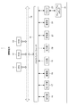
携帯端末1は、図1に示すように、CPU(Central Processing Unit)11と、ROM(Read Only Memory)12と、RAM(Random Access Memory)13と、バス14と、入出力インターフェース15と、GPS部16と、センサ部17と、撮像部18と、入力部19と、出力部20と、記憶部21と、通信部22と、ドライブ23と、を備えている。
As shown in FIG. 1, the
CPU11は、ROM12に記録されているプログラム、又は、記憶部21からRAM13にロードされたプログラムに従って各種の処理を実行する。
The
RAM13には、CPU11が各種の処理を実行する上において必要なデータ等も適宜記憶される。
Data and the like necessary for the
CPU11、ROM12及びRAM13は、バス14を介して相互に接続されている。このバス14にはまた、入出力インターフェース15も接続されている。入出力インターフェース15には、GPS部16、センサ部17、撮像部18、入力部19、出力部20、記憶部21、通信部22及びドライブ23が接続されている。
The
GPS部16は、図示しないGPS受信アンテナを介して、複数のGPS衛星からのGPS信号を受信する。CPU11は、GPS部16が受信したGPS信号に基づいて、機器の現在位置を示す緯度及び経度、高度の情報等の位置情報を取得する。
The
センサ部17は、ジャイロ、加速度、地磁気、GPSの各種のセンシングを行って、姿勢情報や位置情報を出力する。 The sensor unit 17 performs various sensing of gyro, acceleration, geomagnetism, and GPS, and outputs attitude information and position information.
撮像部18は、図示はしないが、光学レンズ部と、イメージセンサと、を備えている。
Although not shown, the
光学レンズ部は、被写体を撮影するために、光を集光するレンズ、例えばフォーカスレンズやズームレンズ等で構成される。
フォーカスレンズは、イメージセンサの受光面に被写体像を結像させるレンズである。ズームレンズは、焦点距離を一定の範囲で自在に変化させるレンズである。
光学レンズ部にはまた、必要に応じて、焦点、露出、ホワイトバランス等の設定パラメータを調整する周辺回路が設けられる。
The optical lens unit is composed of a lens that collects light, such as a focus lens or a zoom lens, in order to photograph a subject.
The focus lens is a lens that forms a subject image on the light receiving surface of the image sensor. A zoom lens is a lens that freely changes the focal length within a certain range.
The optical lens unit is also provided with peripheral circuits for adjusting setting parameters such as focus, exposure, and white balance, if necessary.
イメージセンサは、光電変換素子や、AFE(Analog Front End)等から構成される。
光電変換素子は、例えばCMOS(Complementary Metal Oxide Semiconductor)型の光電変換素子等から構成される。光電変換素子には、光学レンズ部から被写体像が入射される。そこで、光電変換素子は、被写体像を光電変換(撮像)して画像信号を一定時間蓄積し、蓄積した画像信号をアナログ信号としてAFEに順次供給する。
AFEは、このアナログの画像信号に対して、A/D(Analog/Digital)変換処理等の各種信号処理を実行する。各種信号処理によって、デジタル信号が生成され、撮像部18の出力信号として出力される。
このような撮像部18の出力信号を撮像画像のデータとして、CPU11や図示しない画像処理部等に適宜供給される。
The image sensor is composed of a photoelectric conversion element, an AFE (Analog Front End), and the like.
The photoelectric conversion element is composed of, for example, a CMOS (Complementary Metal Oxide Semiconductor) type photoelectric conversion element or the like. A subject image is incident on the photoelectric conversion element from the optical lens unit. Therefore, the photoelectric conversion element performs photoelectric conversion (imaging) of the subject image, accumulates an image signal for a certain period of time, and sequentially supplies the accumulated image signal as an analog signal to AFE.
The AFE executes various signal processing such as A / D (Analog / Digital) conversion processing on the analog image signal. A digital signal is generated by various signal processing and is output as an output signal of the
The output signal of the
入力部19は、各種釦等で構成され、ユーザの指示操作に応じて各種情報を入力する。
出力部20は、ディスプレイやスピーカ等で構成され、画像や音声を出力する。
本実施形態においては、画像やアイコン等を表示するディスプレイとなる出力部20にタッチやスワイプ等の入力操作可能な入力部19が重畳的に配置されて、インターフェースとなるタッチパネルを構成する。
The
The
In the present embodiment, an
記憶部21は、ハードディスク或いはDRAM(Dynamic Random Access Memory)等で構成され、各種画像のデータを記憶する。
The
通信部22は、インターネットを含むネットワークを介して他の装置(図示せず)との間で行う通信を制御する。
The
ドライブ23には、磁気ディスク、光ディスク、光磁気ディスク、或いは半導体メモリ等よりなる、リムーバブルメディア31が適宜装着される。ドライブ23によってリムーバブルメディア31から読み出されたプログラムは、必要に応じて記憶部21にインストールされる。また、リムーバブルメディア31は、記憶部21に記憶されている画像のデータ等の各種データも、記憶部21と同様に記憶することができる。
A
このように構成される携帯端末1では、時計表示おいて、アナログ時計表示を行う機能を有する。アナログ時計表示では、針と重畳しない位置に、選択された機能に対応した情報(以下、「提示情報」という。)が表示される。即ち、携帯端末1では、時刻と共に移動する針を避けて、提示情報が表示される。
The
図2は、本実施形態におけるアナログ時計表示を説明するための模式図である。
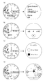
本実施形態のアナログ時計表示は、図2(a)に示すように、表示画面の中央を回転中心として、時刻を表示する針画像HH,MH,SHが配置されて時計のアナログ時計表示がされる。また、本実施形態においては、例えば、初期設定状態では、アナログ時計表示の背面に、選択された機能に即した提示情報が予め設定された領域(以下、「基準表示領域」という。)R0に表示される。
本実施形態の携帯端末1では、針と提示情報とが重畳した場合に、提示情報を重畳しない他の領域に表示させる機能を有するが、本機能を発揮させた場合には、図2(b)の例に示すように、時を示す短針の針画像HH、分を示す長針の針画像MH、秒を示す秒針の針画像SHの間の領域R1のうち、最も大きい領域(以下、「変更表示領域」という。)R2に表示する。
FIG. 2 is a schematic diagram for explaining the analog clock display in the present embodiment.
In the analog clock display of the present embodiment, as shown in FIG. 2A, hand images HH, MH, SH for displaying the time are arranged with the center of the display screen as the center of rotation, and the analog clock display of the clock is performed. To. Further, in the present embodiment, for example, in the initial setting state, on the back surface of the analog clock display, a region (hereinafter, referred to as “reference display region”) R0 in which presentation information corresponding to the selected function is preset is set. Is displayed.
The
なお、本例では、時を示す短針(時針)の針画像HH、分を示す長針(分針)の針画像MH、秒を示す秒針の針画像SHの間の領域R1のうちで表示するように構成したが、時を示す短針の針画像HHと、分を示す長針の針画像MHの間の領域だけで判断してもよい。また、短針と画面の周縁部の間の領域も表示領域として扱って、変更表示領域を構成するようにしてもよい。その場合、領域のサイズにあうように提示情報の表示態様を変更して表示させるよう制御する。
また、例えば、装飾的な特殊な形状のものであったり太かったり等の針画像の形状に応じて、針画像間の領域を設定するよう制御する。
In this example, the area R1 between the hand image HH of the short hand (hour hand) indicating the hour, the hand image MH of the long hand (minute hand) indicating the minute, and the hand image SH of the second hand indicating the second is displayed. Although it is configured, it may be judged only by the region between the short hand image HH indicating the hour and the long hand image MH indicating the minute. Further, the area between the short hand and the peripheral edge of the screen may be treated as a display area to form a changed display area. In that case, the display mode of the presented information is changed and displayed so as to match the size of the area.
Further, for example, the area between the needle images is controlled to be set according to the shape of the needle image such as a decorative special shape or a thick needle image.
また、図2(c)の例に示すように、各針画像が重なる時刻である場合には、重なっている位置と対称的な位置を、変更表示領域R2とするように構成してもよい。
さらに、図2(d)の例に示すように、複数の領域を、変更表示領域R2とするように構成してもよい。複数の領域を変更表示領域R2とする場合には、種類の異なる情報(提示情報やその他の情報を含む。)を表示するように構成してもよい。
Further, as shown in the example of FIG. 2C, when the time is such that the hand images overlap, the position symmetrical with the overlapping position may be configured to be the change display area R2. ..
Further, as shown in the example of FIG. 2D, a plurality of areas may be configured to be a change display area R2. When a plurality of areas are designated as the change display area R2, different types of information (including presentation information and other information) may be displayed.
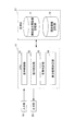
図3は、図1の携帯端末1の機能的構成のうち、情報表示処理を実行するための機能的構成を示す機能ブロック図である。
情報表示処理とは、時計のアナログ時計表示において、表示時点における時刻の針画像の位置と提示情報の位置とが重畳してしまうと判定された場合に針画像又は提示情報の表示態様を変更して表示する一連の処理をいう。
FIG. 3 is a functional block diagram showing a functional configuration for executing information display processing among the functional configurations of the
The information display process changes the display mode of the hand image or the presentation information when it is determined that the position of the hand image of the time at the time of display and the position of the presentation information overlap in the analog clock display of the clock. Refers to a series of processes to be displayed.
情報表示処理を実行する場合には、図3に示すように、CPU11において、表示制御部51と、指示検出部52と、重畳判定部53と、表示態様決定部54と、が機能する。
When the information display process is executed, as shown in FIG. 3, the
また、記憶部21の一領域には、時刻表示用画像記憶部71と、提供情報記憶部72と、が設定される。
時刻表示用画像記憶部71には、例えば、短針、長針、秒針等のアナログ時計表示に必要な針画像、時刻のインデックス画像等の時刻表示用画像のデータが記憶される。
提供情報記憶部72は、種々の機能に対応する提供情報が記憶される。
提供情報は、例えば、時刻のデジタル情報、GPS部16やセンサ部17からのセンサ情報、受信したメッセージ情報、設定したスケジュール情報等々の種々の機能に対応する情報である。
Further, in one area of the
The time display image storage unit 71 stores data of time display images such as hand images necessary for analog clock display such as a short hand, a long hand, and a second hand, and a time index image.
The provided
The provided information is, for example, information corresponding to various functions such as digital time information, sensor information from the
表示制御部51は、時刻に対応して針画像を表示し、針画像の背面側に、時計表示面の所定位置に提供情報を表示するように出力部20を制御する。
また、表示制御部51は、例えば、針画像と提供情報とが重畳して表示されることになると判定された場合には、針画像を避けた位置に提供情報を表示するように出力部20を制御する。本実施形態においては、表示制御部51は、針画像のない領域のうち、最も大きい領域である変更表示領域に提供情報を表示するように出力部20を制御する。
The
Further, for example, when it is determined that the needle image and the provided information are superimposed and displayed, the
指示検出部52は、指示を検出する。指示検出部52は、例えば、提供情報と針画像が重畳した場合に重畳を回避して提供情報を表示する指示(以下、「重畳回避表示指示」という。)を、ユーザ操作により入力部19を介して検出する。なお、重畳回避表示指示は、ユーザ操作に限らず、所定の条件を満たし場合に検出するように構成してもよく、例えば、ユーザが表示を確認するために、装置を傾けたりしたり、ユーザが表示を確認するであろう時刻やアラームの時刻等になったりした場合等を条件として自動的に検出するように構成してもよい。
The
重畳判定部53は、表示している時刻から針画像と提供情報とが重畳しているか否かを判定する。
重畳判定部53は、例えば、初期情報では、図2(a)に示すように、提供情報は基準表示領域R0に表示されているために、当該基準表示領域R0上に針画像が位置する時刻であるかを判定する。また、重畳判定部53は、重畳していると判定されて提供情報の表示位置が変更された場合には、当該変更された変更表示領域R2上に針画像が位置する時刻であるかを判定する。
The
For example, in the initial information, the
表示態様決定部54は、針画像の表示領域に応じて、提供情報の表示態様を決定する。表示態様決定部54は、例えば、針画像と提供情報とが重畳している場合には、提供情報が見えづらくならないように、針画像の位置を避ける位置(変更表示領域)に提供情報を表示するために針画像の位置に基づいて、提示情報の表示位置を決定する。即ち、図2(a)に示すように、表示される時刻から各針画像HH,MH,SHの位置を割り出して、針画像HH,MH,SH間の領域R1を特定して、最も大きい領域を変更表示領域R2として表示位置を決定する。なお、表示態様決定部54は、例えば、針画像のない領域を、例えば、針画像の形状・サイズ、時刻に基づく角度計算等に応じて、特定する。
The display
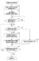
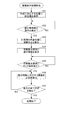
図4は、図3の機能的構成を有する図1の携帯端末1が実行する情報表示処理の流れを説明するフローチャートである。
情報表示処理は、ユーザによる入力部19への情報表示処理開始の操作により開始される。
FIG. 4 is a flowchart illustrating a flow of information display processing executed by the
The information display process is started by the user's operation of starting the information display process on the
ステップS11において、表示制御部51は、表示する時刻に対応する位置に針画像を表示するように出力部20を制御する。
In step S11, the
ステップS12において、表示制御部51は、提示情報を基準表示領域に表示するように出力部20を制御する(図2(a)の例を参照)。
In step S12, the
ステップS13において、指示検出部52は、例えば、ユーザによる入力部19への重畳回避表示指示を検出したか否かを判定する。
重畳回避表示指示を検出していない場合には、ステップS13においてNOと判定されて、処理は待機状態となる。
重畳回避表示指示を検出した場合には、ステップS13においてYESと判定されて、処理はステップS14に進む。
In step S13, the
If the superimposition avoidance display instruction is not detected, NO is determined in step S13, and the process is in the standby state.
When the superposition avoidance display instruction is detected, YES is determined in step S13, and the process proceeds to step S14.
ステップS14において、重畳判定部53は、時刻に対応する針画像の位置と、提示情報が表示された情報表示領域とが重複しているか否かを判定する。
針画像と提示情報との表示位置が重複している場合には、ステップS14においてYESと判定されて、処理はステップS16に進む。
針画像と提示情報との表示位置が重複していない場合には、ステップS14においてNOと判定されて、処理はステップS15に進む。
In step S14, the
If the display positions of the needle image and the presented information overlap, YES is determined in step S14, and the process proceeds to step S16.
If the display positions of the needle image and the presented information do not overlap, NO is determined in step S14, and the process proceeds to step S15.
ステップS15において、表示制御部51は、提示情報の表示位置を変更せずに、針画像及び提示情報を表示するように出力部20を制御する。その後、処理はステップS18に進む。
In step S15, the
ステップS16において、表示態様決定部54は、針画像の位置から変更表示領域を決定する。例えば、表示態様決定部54は、各針画像HH,MH,SMの間の領域R1のうち、最も広い領域を変更表示領域R2として決定する(図2(b)を参照)。
In step S16, the display
ステップS17において、表示制御部51は、提示情報の表示位置を変更表示領域に変更して表示するように出力部20を制御する。
In step S17, the
ステップS18において、指示検出部52は、例えば、ユーザによる入力部19への重畳回避表示指示の終了指示を検出した否かを判定する。
終了指示を検出していない場合には、ステップS18においてNOと判定されて、処理はステップS14に戻る。
終了指示を検出した場合には、ステップS18においてYESと判定されて、情報表示処理は終了する。
In step S18, the
If the end instruction is not detected, NO is determined in step S18, and the process returns to step S14.
When the end instruction is detected, YES is determined in step S18, and the information display process ends.
<変形例>
上述した実施形態では、針の配置状況に応じて、針画像のない領域、即ち、針画像と重複しない位置に提示情報を表示するように構成したが、本例では、提示情報を表示するにあたって針側が予め決められた特定の位置に移動して、提示情報の表示領域を確保するように構成する。
<Modification example>
In the above-described embodiment, the presentation information is displayed in a region without the needle image, that is, in a position that does not overlap with the needle image, depending on the arrangement of the needles. However, in this example, the presentation information is displayed. The needle side is configured to move to a predetermined specific position to secure a display area for the presented information.
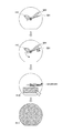
図5は、本実施形態におけるアナログ時計表示の他の例を説明するための模式図である。
本実施形態のアナログ時計表示の情報表示処理の他の例は、図5に示すように、まず、所定の時刻(本実施形態においては、現在時刻)を表示している状態において、提示情報の表示を行うための指示が検出されると、全ての針(時針HH,分針MH,秒針SH)が所定の位置に待避するように回転する。本実施形態においては、待避位置は、3時の位置とする。また、針が待避する動き(回転動作)をアニメーションによって逐次表示する。本実施形態においては、各針の位置に応じて、回転方向が異なるように動くように表示する。なお、全ての針が同一方向に動くように構成してもよいし、動きの順番や速度を変えたりして構成してもよい。また、針が待避している状態においては、時刻が表示されていない状態となるため、別途時刻表示を行うように構成してもよい。この場合、例えば、情報表示領域R10に時刻(アナログ/デジタル)を表示したり、空いている領域や針の近傍に時刻(アナログ/デジタル)を表示したりするようにしてもよい。これによりユーザは、針が待避している状態においても、常に時刻を把握することができるようになる。
FIG. 5 is a schematic diagram for explaining another example of the analog clock display in the present embodiment.
As another example of the information display processing of the analog clock display of the present embodiment, as shown in FIG. 5, first, in a state where a predetermined time (current time in the present embodiment) is displayed, the presented information is displayed. When an instruction for displaying is detected, all the hands (hour hand HH, minute hand MH, second hand SH) rotate so as to evacuate to a predetermined position. In the present embodiment, the shunting position is the 3 o'clock position. In addition, the movement (rotational movement) of the needle shunting is sequentially displayed by animation. In the present embodiment, it is displayed so as to move in a different rotation direction according to the position of each needle. It should be noted that the needles may be configured to move in the same direction, or the order and speed of movement may be changed. Further, since the time is not displayed when the hands are retracted, the time may be displayed separately. In this case, for example, the time (analog / digital) may be displayed in the information display area R10, or the time (analog / digital) may be displayed in a vacant area or in the vicinity of the hands. As a result, the user can always grasp the time even when the hands are retracted.
上述した情報表示処理では、全ての針が同じ場所に待避することによって、提示情報を表示する領域が確保される。また、全ての針が同じ場所に待避することによって、針画像に注意が削がれることがなく、提示情報へユーザが注目出来るようになるため視認性を高めることができる。 In the information display process described above, the area for displaying the presented information is secured by retracting all the needles to the same place. Further, by retracting all the needles to the same place, the needle image is not distracted and the user can pay attention to the presented information, so that the visibility can be improved.
針が待避した結果、針画像と重複しない領域のうち、特定の領域(本実施形態においては、情報表示領域R10)に提示情報が表示される。 As a result of the needle retracting, the presented information is displayed in a specific area (information display area R10 in the present embodiment) among the areas that do not overlap with the needle image.
その後、タッチ操作等で、情報表示領域R10が指定された場合には、表示されている提示情報に対応した機能の画面を全画面(全画面領域R11)での表示がされて、機能に即した動作及び表示が行われる。 After that, when the information display area R10 is specified by a touch operation or the like, the screen of the function corresponding to the displayed presentation information is displayed in full screen (full screen area R11), and the function is immediately displayed. The operation and display are performed.
図6及び図7は、本実施形態における提示情報と対応する機能の全画面表示の例を示す模式図である。
図6(a)の例に示すように、直近のスケジュールを提示情報として表示し、スケジュール機能を全画面表示する。
図6(b)の例に示すように、翻訳機能が発揮可能である旨を提示情報として表示し、翻訳機能を全画面表示する。
図6(c)の例に示すように、ホームタウン登録された都市の都市名と時刻を提示情報として表示し、ホームタウン登録機能を全画面表示する。
図6(d)の例に示すように、現在地の周辺の地図を提示情報として表示し、現在地の周辺の地図表示を含む地図表示機能を全画面表示する。
図7(a)の例に示すように、現在の気圧と気圧変化のグラフを提示情報として表示し、気圧計表示機能を全画面表示する。
図7(b)の例に示すように、方位を提示情報として表示し、コンパス表示機能を全画面表示する。
図7(c)の例に示すように、高度と高度変化のグラフを提示情報として表示し、高度表示機能を全画面表示する。
6 and 7 are schematic views showing an example of full-screen display of the function corresponding to the presented information in the present embodiment.
As shown in the example of FIG. 6A, the latest schedule is displayed as presentation information, and the schedule function is displayed in full screen.
As shown in the example of FIG. 6B, the fact that the translation function can be exhibited is displayed as presentation information, and the translation function is displayed in full screen.
As shown in the example of FIG. 6C, the city name and time of the city registered as hometown are displayed as presentation information, and the hometown registration function is displayed in full screen.
As shown in the example of FIG. 6D, the map around the current location is displayed as presentation information, and the map display function including the map display around the current location is displayed in full screen.
As shown in the example of FIG. 7A, the graph of the current atmospheric pressure and the atmospheric pressure change is displayed as the presentation information, and the barometer display function is displayed in full screen.
As shown in the example of FIG. 7B, the direction is displayed as presentation information, and the compass display function is displayed in full screen.
As shown in the example of FIG. 7C, the graph of altitude and altitude change is displayed as presentation information, and the altitude display function is displayed in full screen.
図8は、図3の機能的構成を有する図1の携帯端末1が実行する情報表示処理の他の流れを説明するフローチャートである。
情報表示処理は、ユーザによる入力部19への情報表示処理開始の操作により開始される。
FIG. 8 is a flowchart illustrating another flow of information display processing executed by the
The information display process is started by the user's operation of starting the information display process on the
ステップS31において、表示制御部51は、表示する時刻に対応する位置に針画像を表示するように出力部20を制御する(図5を参照)。
In step S31, the
ステップS32において、指示検出部52は、例えば、ユーザによる入力部19への提示情報表示指示を検出したか否かを判定する。
提示情報表示指示を検出していない場合には、ステップS32においてNOと判定されて、処理は待機状態となる。
提示情報表示指示を検出した場合には、ステップS32においてYESと判定されて、処理はステップS33に進む。
In step S32, the
If the presentation information display instruction is not detected, NO is determined in step S32, and the process is in the standby state.
When the presentation information display instruction is detected, YES is determined in step S32, and the process proceeds to step S33.
ステップS33において、表示制御部51は、針画像を待避位置(本実施形態においては、3時の位置)に移動させる動きをアニメーションで表示するように出力部20を制御する(図5を参照)。
In step S33, the
ステップS34において、表示制御部51は、情報表示領域に提示情報を表示するように出力部20を制御する(図5を参照)。
In step S34, the
ステップS35において、指示検出部52は、例えば、ユーザによる情報表示領域へのタッチ操作を検出したか否かを判定する。
情報表示領域へのタッチ操作を検出していない場合には、ステップS35においてNOと判定されて、処理は待機状態となる。
情報表示領域へのタッチ操作を検出した場合には、ステップS35においてYESと判定されて、処理はステップS36に進む。
In step S35, the
If the touch operation to the information display area is not detected, NO is determined in step S35, and the process is in the standby state.
When a touch operation to the information display area is detected, YES is determined in step S35, and the process proceeds to step S36.
ステップS36において、表示制御部51は、提示情報に対応する機能を全画面表示するように出力部20を制御する。その後、操作等によって、例えば、図5に示すように機能の表示と、機能に即した動作及び表示(図6及び図7を参照)が行われる。
In step S36, the
ステップS37において、指示検出部52は、例えば、ユーザによる入力部19への表示の終了指示を検出した否かを判定する。
表示の終了指示を検出していない場合には、ステップS37においてNOと判定されて、処理はステップS36に戻る。
表示の終了指示を検出した場合には、ステップS37においてYESと判定されて、情報表示処理は終了する。
In step S37, the
If the display end instruction is not detected, NO is determined in step S37, and the process returns to step S36.
When the display end instruction is detected, YES is determined in step S37, and the information display process ends.
上述した実施形態では、重畳回避表示指示を検出した後に、重畳と判定された場合に、表示態様を変更する処理を実行するように構成したが、これに限られない。例えば、重畳回避表示指示の検出のみで表示態様を変更する処理を実行するようにしてもよいし、指示に限らず重複を判定した結果で表示態様を変更する処理を実行するようにしてもよい。
また、上述した実施形態では、表示態様の内容についても、針画像の位置から提示情報の表示位置を変更したり、固定の情報表示領域を設けて針画像を所定の位置に退避させるようにしたり、針画像や提示情報の透過度を変更したりするようにすることができ、種々の条件に応じて、表示態様の内容を変更するように構成してもよい。
例えば、ユーザによる予めの設定であったり、針画像の位置であったり、ユーザが時刻か提示情報を確認する操作や仕草や装置の姿勢であったり、スケジュールやメッセージを受信したり、所定の位置に移動した場合であったり等の条件で表示態様の内容を変えるように構成してもよい。
In the above-described embodiment, after detecting the superimposition avoidance display instruction, when it is determined that superimposition is performed, the process of changing the display mode is executed, but the present invention is not limited to this. For example, a process of changing the display mode only by detecting the superposition avoidance display instruction may be executed, or a process of changing the display mode based on the result of determining duplication is not limited to the instruction. ..
Further, in the above-described embodiment, regarding the content of the display mode, the display position of the presented information is changed from the position of the needle image, or a fixed information display area is provided so that the needle image is retracted to a predetermined position. , The transparency of the needle image and the presented information can be changed, and the content of the display mode may be changed according to various conditions.
For example, it is set in advance by the user, it is the position of the needle image, it is the operation that the user confirms the time or the presented information, the posture of the gesture or the device, the schedule or the message is received, or the predetermined position. The content of the display mode may be changed depending on the conditions such as when the image is moved to.
以上のように構成される携帯端末1は、出力部20を有する電子機器である。
携帯端末1は、表示制御部51と、重畳判定部53と、を備える。
表示制御部51は、針画像を取得する。また、表示制御部51は、所定の情報である提示情報を取得する。また、表示制御部51は、針画像を現在時刻に応じた位置に表示させると共に、当該針画像の表示位置の近傍において、所定の情報である提示情報を表示させるように出力部20を制御する。
重畳判定部53は、表示制御部51によって針画像と所定の情報である提示情報と針画像とが重畳して表示されているか否かを判定する。
表示制御部51は、重畳判定部53によって針画像と所定の情報である提示情報とが重畳して表示されていると判定された場合に、当該針画像と当該所定の情報である提示情報の表示領域が重複しないように表示態様を変更する。
これにより、携帯端末1においては、アナログ時計表示のデザイン性を保ちつつ、ユーザが容易に針画像によって表現される時刻情報とは異なる情報を読取り可能な表示制御を行うことができる。
The
The
The
The
When the
As a result, the
表示制御部51は、表示態様として、針画像に重畳しないように所定の情報である提示情報の表示位置又は表示サイズを変更する。
これにより、携帯端末1においては、アナログ時計表示のデザイン性を保ちつつ、ユーザが容易に針画像によって表現される時刻情報とは異なる情報を読取り可能な表示制御を行うことができる。
As a display mode, the
As a result, the
表示制御部51は、針画像と所定の情報である提示情報とが重畳して表示されていると判定された場合に、当該針画像と当該所定の情報である提示情報とが重畳して表示されないように表示態様を変更する。
これにより、携帯端末1においては、アナログ時計表示のデザイン性を保ちつつ、ユーザが容易に針画像によって表現される時刻情報とは異なる情報を読取り可能な表示制御を行うことができる。
When it is determined that the needle image and the presentation information which is the predetermined information are superimposed and displayed, the
As a result, the
表示態様決定部54は、所定の情報である提示情報の表示領域として当該所定の情報である提示情報の表示位置及び表示サイズを算出する。
表示態様決定部54は、針画像と所定の情報とが重畳して表示されていると判定された場合に、算出される表示領域に基づいて針画像を移動させるように表示位置を変更する。
これにより、携帯端末1においては、提示情報の表示位置や表示サイズに応じて針画像を移動させることができる。
The display
The display
As a result, in the
表示制御部51は、針画像を所定の待避位置に移動させるように表示位置を変更させた場合、所定の情報の表示領域に針画像を用いずに時刻情報を表示させる。
これにより、携帯端末1においては、針画像が待避してアナログ表示が行われなくなった場合でも、ユーザは時刻を確認することができる。
When the display position is changed so as to move the needle image to a predetermined save position, the
As a result, in the
表示制御部51は、出力部20に表示される針画像の表示位置及び表示サイズに応じて、所定の情報である提示情報の表示形態を変更する。
これにより、携帯端末1においては、アナログ時計表示のデザイン性を保ちつつ、ユーザが容易に針画像によって表現される時刻情報とは異なる情報を読取り可能な表示制御を行うことができる。
The
As a result, the
表示制御部51は、表示態様の変更前から変更後に至る動きをアニメーションによって表示させる。
これにより、携帯端末1においては、表示態様の変更をユーザに違和感を与えることなく行うことができる。
The
As a result, in the
表示制御部51は、針画像の表示態様のうち、表示位置を変更する場合には、針画像の時刻表示における動きに対応した動きで、表示態様の変更前から変更後に至る動きをアニメーションによって表示する。
これにより、携帯端末1においては、針画像の表示位置の変更について、通常の時刻表示の動きと同様の動きで行うことができ、ユーザに違和感を与えることなく表示態様の変更を行うことができる。
When the display position of the needle image is changed, the
As a result, in the
なお、本発明は、上述の実施形態に限定されるものではなく、本発明の目的を達成できる範囲での変形、改良等は本発明に含まれるものである。 The present invention is not limited to the above-described embodiment, and modifications, improvements, and the like within the range in which the object of the present invention can be achieved are included in the present invention.
上述の実施形態では、表示態様として、提示情報の位置を変更するように構成したが、例えば、提示情報の位置、サイズ(例えば、小さいサイズに変更)、形状又は透過度、表示レイヤー(前景、後景)等を変更するように構成してもよい。なお、透過度を変更した場合、針画像の透過度を高くして、提示情報よりも薄い状態になるようにしたり、提示情報の透過度を低くして針画像よりも逆に濃くしたりするように構成することができる。また、色彩や色の濃淡を変えて表現してもよい。また、透過度等を変える場合は、針画像又は提示情報の一方が消える状態も含む。 In the above-described embodiment, the display mode is configured to change the position of the presentation information, for example, the position, size (for example, change to a smaller size), shape or transparency, display layer (foreground,) of the presentation information. The background) and the like may be changed. When the transparency is changed, the transparency of the needle image is increased so that it becomes thinner than the presented information, or the transparency of the presented information is decreased to make it darker than the needle image. It can be configured as follows. Further, the color and the shade of the color may be changed for expression. In addition, when changing the transparency or the like, it also includes a state in which one of the needle image and the presented information disappears.
また、上述の実施形態では、提示情報側の表示態様を変更するように構成したが、針画像側の表示態様を変更するように構成してもよい。例えば、針画像の位置、サイズ(例えば、小さいサイズに変更)、形状又は透過度等を変更するように構成してもよい。また、針画像は、固定的に所定の待避位置(例えば、3時の位置等)を設けて移動させるように構成してもよい。 Further, in the above-described embodiment, the display mode on the presentation information side is changed, but the display mode on the needle image side may be changed. For example, the position, size (for example, change to a smaller size), shape or transparency of the needle image may be changed. Further, the needle image may be configured to be fixedly provided with a predetermined shunting position (for example, the position at 3 o'clock) and moved.
また、上述の実施形態では、針画像や提示情報の変更表示領域への移動の描写は、例えば、連続的に移動させたり、位置を離散的に移動させたりすることができる。また、例えば、遠い場合は早く・近いとゆっくり等の針画像の距離や移動量に応じた動きで移動の速度を制御するように構成してもよい。なお、バッテリ残量を考慮して、移動の描写を変更するように制御してもよい。
例えば、針画像又は提示情報の表示態様を変更する際に、現在の表示状態から最終の表示状態に連続的に変化するように変更するように構成することができる。
Further, in the above-described embodiment, the depiction of the movement of the needle image or the presentation information to the change display area can be, for example, continuously moved or the position can be moved discretely. Further, for example, the speed of movement may be controlled by movement according to the distance and the amount of movement of the needle image, such as fast when it is far and slow when it is near. It should be noted that the movement may be controlled to be changed in consideration of the remaining battery level.
For example, when the display mode of the needle image or the presentation information is changed, it can be configured to be changed so as to continuously change from the current display state to the final display state.
また、上述の実施形態では、重複回避指示をユーザによる操作をトリガとして行うように構成したが自動で行うように構成してもよい。自動で行う場合には、タッチ操作・行動判定・手首の動き(チルト変化)・時刻(スケジュール)・位置(特定の場所に来たか否か)等を、GPS部16、センサ部17でのセンサ情報や予め設定されたスケジュール情報等を用いて、所定の状態を検出したことをトリガとしてもよい。なお、バッテリ残量を考慮して、トリガを変更するように制御してもよい。
Further, in the above-described embodiment, the duplication avoidance instruction is configured to be triggered by an operation by the user, but may be configured to be automatically performed. When performing automatically, touch operation, action judgment, wrist movement (tilt change), time (schedule), position (whether or not you have come to a specific place), etc. are detected by
また、上述の実施形態では、現在時刻を表示するように構成したが、例えば、特定の時刻、ユーザが設定した架空の時刻、現在時刻に対して所定時間(前倒し・後ろ倒し)ずれた時刻等を表示するように構成してもよい。 Further, in the above-described embodiment, the current time is displayed, but for example, a specific time, a fictitious time set by the user, a time deviated by a predetermined time (advanced / backward) from the current time, etc. May be configured to display.
また、上述の実施形態では、本発明が適用される携帯端末1は、スマートウォッチを例として説明したが、特にこれに限定されない。
例えば、本発明は、情報表示処理機能を有する電子機器一般に適用することができる。具体的には、例えば、本発明は、ノート型のパーソナルコンピュータ、プリンタ、テレビジョン受像機、ビデオカメラ、デジタルカメラ、携帯型ナビゲーション装置、携帯電話機、スマートフォン、ポータブルゲーム機等に適用可能である。
Further, in the above-described embodiment, the
For example, the present invention can be generally applied to electronic devices having an information display processing function. Specifically, for example, the present invention can be applied to notebook personal computers, printers, television receivers, video cameras, digital cameras, portable navigation devices, mobile phones, smartphones, portable game machines, and the like.
上述した一連の処理は、ハードウェアにより実行させることもできるし、ソフトウェアにより実行させることもできる。
換言すると、図3の機能的構成は例示に過ぎず、特に限定されない。即ち、上述した一連の処理を全体として実行できる機能が携帯端末1に備えられていれば足り、この機能を実現するためにどのような機能ブロックを用いるのかは特に図3の例に限定されない。
また、1つの機能ブロックは、ハードウェア単体で構成してもよいし、ソフトウェア単体で構成してもよいし、それらの組み合わせで構成してもよい。
本実施形態における機能的構成は、演算処理を実行するプロセッサによって実現され、本実施形態に用いることが可能なプロセッサには、シングルプロセッサ、マルチプロセッサ及びマルチコアプロセッサ等の各種処理装置単体によって構成されるものの他、これら各種処理装置と、ASIC(Application Specific Integrated Circuit)やFPGA(Field‐Programmable Gate Array)等の処理回路とが組み合わせられたものを含む。
The series of processes described above can be executed by hardware or software.
In other words, the functional configuration of FIG. 3 is merely an example and is not particularly limited. That is, it suffices if the
Further, one functional block may be configured by a single piece of hardware, a single piece of software, or a combination thereof.
The functional configuration in this embodiment is realized by a processor that executes arithmetic processing, and the processor that can be used in this embodiment is composed of various processing units such as a single processor, a multiprocessor, and a multicore processor. In addition to the CPUs, these various processing units include those in which processing circuits such as ASIC (Application Specific Integrated Circuit) and FPGA (Field-Programmable Gate Array) are combined.
一連の処理をソフトウェアにより実行させる場合には、そのソフトウェアを構成するプログラムが、コンピュータ等にネットワークや記録媒体からインストールされる。
コンピュータは、専用のハードウェアに組み込まれているコンピュータであってもよい。また、コンピュータは、各種のプログラムをインストールすることで、各種の機能を実行することが可能なコンピュータ、例えば汎用のパーソナルコンピュータであってもよい。
When a series of processes are executed by software, the programs constituting the software are installed on a computer or the like from a network or a recording medium.
The computer may be a computer embedded in dedicated hardware. Further, the computer may be a computer capable of executing various functions by installing various programs, for example, a general-purpose personal computer.
このようなプログラムを含む記録媒体は、ユーザにプログラムを提供するために装置本体とは別に配布される図1のリムーバブルメディア31により構成されるだけでなく、装置本体に予め組み込まれた状態でユーザに提供される記録媒体等で構成される。リムーバブルメディア31は、例えば、磁気ディスク(フロッピディスクを含む)、光ディスク、又は光磁気ディスク等により構成される。光ディスクは、例えば、CD−ROM(Compact Disk−Read Only Memory),DVD(Digital Versatile Disk),Blu−ray(登録商標) Disc(ブルーレイディスク)等により構成される。光磁気ディスクは、MD(Mini−Disk)等により構成される。また、装置本体に予め組み込まれた状態でユーザに提供される記録媒体は、例えば、プログラムが記録されている図1のROM12や、図1の記憶部21に含まれるハードディスク等で構成される。
The recording medium including such a program is not only composed of the
なお、本明細書において、記録媒体に記録されるプログラムを記述するステップは、その順序に沿って時系列的に行われる処理はもちろん、必ずしも時系列的に処理されなくとも、並列的或いは個別に実行される処理をも含むものである。 In the present specification, the steps for describing a program recorded on a recording medium are not necessarily processed in chronological order, but also in parallel or individually, even if they are not necessarily processed in chronological order. It also includes the processing to be executed.
以上、本発明のいくつかの実施形態について説明したが、これらの実施形態は、例示に過ぎず、本発明の技術的範囲を限定するものではない。本発明はその他の様々な実施形態を取ることが可能であり、さらに、本発明の要旨を逸脱しない範囲で、省略や置換等種々の変更を行うことができる。これら実施形態やその変形は、本明細書等に記載された発明の範囲や要旨に含まれるとともに、特許請求の範囲に記載された発明とその均等の範囲に含まれる。 Although some embodiments of the present invention have been described above, these embodiments are merely examples and do not limit the technical scope of the present invention. The present invention can take various other embodiments, and various modifications such as omission and substitution can be made without departing from the gist of the present invention. These embodiments and modifications thereof are included in the scope and gist of the invention described in the present specification and the like, and are also included in the scope of the invention described in the claims and the equivalent scope thereof.
以下に、本願の出願当初の特許請求の範囲に記載された発明を付記する。
[付記1]
表示部を有する時計において、
針画像を取得する針画像取得手段と、
所定の情報を取得する情報取得手段と、
前記針画像取得手段によって取得された前記針画像を、現在時刻に応じた位置に表示させると共に、当該針画像の表示位置の近傍において、前記情報取得手段によって取得された前記所定の情報を表示させるように前記表示部を制御する表示制御手段と、
前記表示制御手段によって前記所定の情報の表示領域と前記針画像とが重畳して表示される場合に、当該針画像又は当該所定の情報の表示領域が重畳しないよう表示態様を変更する表示変更手段と、
を備えることを特徴とする時計。
[付記2]
前記表示変更手段は、前記表示態様として、前記針画像若しくは前記所定の情報の表示位置、表示サイズ、形状又は透過度を変更する、
ことを特徴とする付記1に記載の時計。
[付記3]
前記表示制御手段によって前記所定の情報の表示領域と、前記針画像とが重畳して表示されるか否かを判定する判定手段を更に備え、
前記表示変更手段は、前記判定手段によって前記所定の情報の表示領域と前記針画像とが重畳して表示されると判定された場合に、当該針画像又は当該所定の情報の表示領域が重畳しないよう表示態様を変更する、
ことを特徴とする付記1又は2に記載の時計。
[付記4]
前記表示変更手段は、前記判定手段によって前記所定の情報の表示領域と前記針画像とが重畳して表示されていると判定された場合に、当該針画像と当該所定の情報とが重畳して表示されないように表示態様を変更する、
ことを特徴とする付記3に記載の時計。
[付記5]
前記表示変更手段は、前記表示態様として、前記所定の情報の表示領域に重畳しないように前記針画像の表示位置又は表示サイズを変更する、
ことを特徴とする付記1乃至4のいずれか1つに記載の時計。
[付記6]
前記表示変更手段は、前記針画像を所定の待避位置に移動させるように表示位置を変更する、
ことを特徴とする付記1乃至5のいずれか1つに記載の時計。
[付記7]
前記表示変更手段は、前記針画像を所定の待避位置に移動させるように表示位置を変更させた場合、前記所定の情報の表示領域に前記針画像を用いずに時刻情報を表示させる、
ことを特徴とする付記6に記載の時計。
[付記8]
前記表示変更手段は、前記所定の情報の表示領域として当該所定の情報の表示位置及び表示サイズを算出する算出手段を備え、
前記表示変更手段は、前記針画像を所定の待避位置に移動させるように表示位置を変更させた場合、前記算出手段により算出される前記表示領域に基づいて前記針画像を移動させるように表示位置を変更する、
ことを特徴とする付記1乃至7のいずれか1つに記載の時計。
[付記9]
前記表示変更手段は、前記表示態様として、前記針画像に重畳しないように前記所定の情報の表示位置又は表示サイズを変更する、
ことを特徴とする付記1乃至8のいずれか1つに記載の時計。
[付記10]
前記表示変更手段によって前記針画像を所定の待避位置に移動させるように表示位置を変更させた場合、当該針画像又は当該所定の情報の表示態様を変更する、
ことを特徴とする付記1乃至9のいずれか1つに記載の時計。
[付記11]
前記表示変更手段は、前記表示部に表示される前記針画像の表示位置及び表示サイズに応じて、前記所定の情報の表示態様を変更する、
ことを特徴とする付記1乃至10のいずれか1つに記載の時計。
[付記12]
前記表示変更手段は、前記針画像又は前記所定の情報の表示態様を変更する際に、現在の表示状態から最終の表示状態に連続的に変化するように変更する、
ことを特徴とする付記1乃至11のいずれか1つに記載の時計。
[付記13]
表示変更の指示を検出する検出手段を備え、
前記表示変更手段は、前記検出手段によって前記表示変更の指示が検出された場合に、前記表示部の表示変更を行う、
ことを特徴とする付記1乃至12のいずれか1つに記載の時計。
[付記14]
前記表示制御手段は、表示態様の変更前から変更後に至る動きをアニメーションによって表示するように前記表示部を制御する、
ことを特徴とする付記1乃至13のいずれか1つに記載の時計。
[付記15]
前記表示制御手段は、針画像の表示態様のうち、表示位置を変更する場合には、針画像の時刻表示における動きに対応した動きで、表示態様の変更前から変更後に至る動きをアニメーションによって表示するように前記表示部を制御する、
ことを特徴とする付記14に記載の時計。
[付記16]
表示部を有する時計で実行される時計表示制御方法において、
針画像を取得する針画像取得ステップと、
所定の情報を取得する情報取得ステップと、
前記針画像取得ステップによって取得された前記針画像を、現在時刻に応じた位置に表示させると共に、当該針画像の表示位置の近傍において、前記情報取得ステップによって取得された前記所定の情報を表示させるように前記表示部を制御する表示制御ステップと、
前記表示制御ステップによって前記所定の情報の表示領域と前記針画像とが重畳して表示される場合に、当該針画像又は当該所定の情報の表示領域が重畳しないよう表示態様を変更する表示変更ステップと、
を含むことを特徴とする表示制御方法。
[付記17]
表示部を有する時計を制御するコンピュータを、
針画像を取得する針画像取得手段、
所定の情報を取得する情報取得手段、
前記針画像取得手段によって取得された前記針画像を、現在時刻に応じた位置に表示させると共に、当該針画像の表示位置の近傍において、前記情報取得手段によって取得された前記所定の情報を表示させるように前記表示部を制御する表示制御手段、
前記表示制御手段によって前記所定の情報の表示領域と前記針画像とが重畳して表示される場合に、当該針画像又は当該所定の情報の表示領域が重畳しないよう表示態様を変更する表示変更手段、
として機能させることを特徴とするプログラム。
The inventions described in the claims at the time of filing the application of the present application are described below.
[Appendix 1]
In a watch having a display unit
Needle image acquisition means for acquiring needle images,
Information acquisition means for acquiring predetermined information and
The needle image acquired by the needle image acquisition means is displayed at a position corresponding to the current time, and the predetermined information acquired by the information acquisition means is displayed in the vicinity of the display position of the needle image. A display control means for controlling the display unit and
When the display control means superimposes the display area of the predetermined information and the needle image, the display changing means for changing the display mode so that the needle image or the display area of the predetermined information does not overlap. When,
A watch characterized by being equipped with.
[Appendix 2]
The display changing means changes the display position, display size, shape, or transparency of the needle image or the predetermined information as the display mode.
The timepiece according to
[Appendix 3]
The display control means further includes a determination means for determining whether or not the display area of the predetermined information and the needle image are superimposed and displayed.
When it is determined by the determination means that the display area of the predetermined information and the needle image are superimposed and displayed, the display changing means does not overlap the needle image or the display area of the predetermined information. Change the display mode,
The timepiece according to
[Appendix 4]
When it is determined by the determination means that the display area of the predetermined information and the needle image are superimposed and displayed, the display changing means superimposes the needle image and the predetermined information. Change the display mode so that it is not displayed,
The timepiece according to Appendix 3, characterized in that.
[Appendix 5]
As the display mode, the display changing means changes the display position or display size of the needle image so as not to be superimposed on the display area of the predetermined information.
The timepiece according to any one of
[Appendix 6]
The display changing means changes the display position so as to move the needle image to a predetermined escape position.
The timepiece according to any one of
[Appendix 7]
When the display position is changed so as to move the needle image to a predetermined escape position, the display changing means causes the time information to be displayed in the display area of the predetermined information without using the needle image.
The timepiece according to Appendix 6, characterized in that.
[Appendix 8]
The display changing means includes a calculation means for calculating a display position and a display size of the predetermined information as a display area of the predetermined information.
When the display position is changed so as to move the needle image to a predetermined shunting position, the display changing means moves the needle image based on the display area calculated by the calculation means. To change,
The timepiece according to any one of
[Appendix 9]
As the display mode, the display changing means changes the display position or display size of the predetermined information so as not to be superimposed on the needle image.
The timepiece according to any one of
[Appendix 10]
When the display position is changed so as to move the needle image to a predetermined shunting position by the display changing means, the display mode of the needle image or the predetermined information is changed.
The timepiece according to any one of
[Appendix 11]
The display changing means changes the display mode of the predetermined information according to the display position and display size of the needle image displayed on the display unit.
The timepiece according to any one of
[Appendix 12]
When the display mode of the needle image or the predetermined information is changed, the display changing means is changed so as to continuously change from the current display state to the final display state.
The timepiece according to any one of
[Appendix 13]
Equipped with a detection means to detect display change instructions
The display changing means changes the display of the display unit when the detection means detects the instruction to change the display.
The timepiece according to any one of
[Appendix 14]
The display control means controls the display unit so as to display the movement from before the change of the display mode to after the change by animation.
The timepiece according to any one of
[Appendix 15]
When the display position of the needle image is changed, the display control means displays the movement corresponding to the movement of the needle image in the time display by animation from before the change of the display mode to after the change. Control the display unit so as to
The timepiece according to
[Appendix 16]
In the clock display control method executed by a clock having a display unit,
Needle image acquisition step to acquire needle image and
An information acquisition step to acquire predetermined information and
The needle image acquired by the needle image acquisition step is displayed at a position corresponding to the current time, and the predetermined information acquired by the information acquisition step is displayed in the vicinity of the display position of the needle image. A display control step that controls the display unit as described above,
When the display area of the predetermined information and the needle image are superimposed and displayed by the display control step, the display change step of changing the display mode so that the needle image or the display area of the predetermined information is not overlapped. When,
A display control method characterized by including.
[Appendix 17]
A computer that controls a clock with a display
Needle image acquisition means for acquiring needle images,
Information acquisition means for acquiring predetermined information,
The needle image acquired by the needle image acquisition means is displayed at a position corresponding to the current time, and the predetermined information acquired by the information acquisition means is displayed in the vicinity of the display position of the needle image. Display control means for controlling the display unit,
When the display control means superimposes the display area of the predetermined information and the needle image, the display changing means for changing the display mode so that the needle image or the display area of the predetermined information does not overlap. ,
A program characterized by functioning as.
1・・・携帯端末,11・・・CPU,12・・・ROM,13・・・RAM,14・・・バス,15・・・入出力インターフェース,16・・・撮像部,17・・・入力部,18・・・出力部20・・・記憶部21・・・通信部22・・・ドライブ,31・・・リムーバブルメディア,51・・・表示制御部,52・・・指示検出部,53・・・重畳判定部,54・・・表示態様決定部,71・・・時刻表示用画像記憶部,72・・・提供情報記憶部
1 ... Mobile terminal, 11 ... CPU, 12 ... ROM, 13 ... RAM, 14 ... Bus, 15 ... Input / output interface, 16 ... Imaging unit, 17 ... Input unit, 18 ...
Claims (18)
時針、分針及び秒針を含む複数の針画像を取得する針画像取得手段と、
所定の情報を取得する情報取得手段と、
前記針画像取得手段によって取得された前記複数の針画像と、前記情報取得手段によって取得された前記所定の情報とを表示させるように前記表示部を制御する表示制御手段と、
前記複数の針画像と前記所定の情報の表示領域とが重畳しないように前記複数の針画像と前記所定の情報の表示領域とを合成する合成手段と、
を備え、
前記合成手段は、前記所定の情報の表示領域が前記複数の針画像のない領域で、且つ前記複数の針画像の各々で分割される複数の領域のうち、最も大きい領域に位置するように合成し、前記所定の情報の表示領域は、前記最も大きい領域のサイズ及び形状にあうように変更する、
ことを特徴とする時計。 In a watch having a display unit
A hand image acquisition means for acquiring a plurality of hand images including an hour hand, a minute hand, and a second hand ,
Information acquisition means for acquiring predetermined information and
Wherein a plurality of needles image acquired by the needle image acquisition means, and display control means for controlling said display unit so as to display the predetermined information acquired by the information acquisition means,
And combining means for combining said plurality of needle image and the display area of the predetermined said predetermined information and display area and the plurality of needles image so as not to overlap the information,
With
Said combining means, wherein a predetermined region display area without the plurality of needles image information, among the plurality of regions and divided by each of the plurality of needles images, synthesized to be located largest area However, the display area of the predetermined information is changed so as to match the size and shape of the largest area .
A watch that features that.
ことを特徴とする請求項1に記載の時計。 The synthesizing means includes a display changing means for changing a display mode so that the needle image and the display area of the predetermined information do not overlap.
The timepiece according to claim 1.
ことを特徴とする請求項2に記載の時計。 The display changing means changes the display position, display size, shape, or transparency of the needle image or the predetermined information as the display mode.
The timepiece according to claim 2.
されるか否かを判定する判定手段を更に備え、
前記表示変更手段は、前記判定手段によって前記所定の情報の表示領域と前記針画像とが重畳して表示されると判定された場合に、当該針画像又は当該所定の情報の表示領域が重畳しないよう表示態様を変更する、
ことを特徴とする請求項2又は3に記載の時計。 The display control means further includes a determination means for determining whether or not the display area of the predetermined information and the needle image are superimposed and displayed.
When it is determined by the determination means that the display area of the predetermined information and the needle image are superimposed and displayed, the display changing means does not overlap the needle image or the display area of the predetermined information. Change the display mode,
The timepiece according to claim 2 or 3.
ことを特徴とする請求項2乃至4のいずれか1項に記載の時計。 As the display mode, the display changing means changes the display position or display size of the needle image so as not to be superimposed on the display area of the predetermined information.
The timepiece according to any one of claims 2 to 4, characterized in that.
ことを特徴とする請求項2乃至5のいずれか1項に記載の時計。 The display changing means changes the display position so as to move the needle image to a predetermined escape position.
The timepiece according to any one of claims 2 to 5, characterized in that.
ことを特徴とする請求項6に記載の時計。 When the display position is changed so as to move the needle image to a predetermined escape position, the display changing means causes the time information to be displayed in the display area of the predetermined information without using the needle image.
The clock according to claim 6.
前記表示変更手段は、前記針画像を所定の待避位置に移動させるように表示位置を変更させた場合、前記算出手段により算出される前記表示領域に基づいて前記針画像を移動させるように表示位置を変更する、
ことを特徴とする請求項2乃至7のいずれか1項に記載の時計。 The display changing means includes a calculation means for calculating a display position and a display size of the predetermined information as a display area of the predetermined information.
When the display position is changed so as to move the needle image to a predetermined shunting position, the display changing means moves the needle image based on the display area calculated by the calculation means. To change,
The timepiece according to any one of claims 2 to 7, characterized in that.
ことを特徴とする請求項2乃至8のいずれか1項に記載の時計。 As the display mode, the display changing means changes the display position or display size of the predetermined information so as not to be superimposed on the needle image.
The timepiece according to any one of claims 2 to 8, characterized in that.
ことを特徴とする請求項2乃至9のいずれか1項に記載の時計。 When the display position is changed so as to move the needle image to a predetermined shunting position by the display changing means, the display mode of the needle image or the predetermined information is changed.
The timepiece according to any one of claims 2 to 9, wherein the timepiece is characterized in that.
ことを特徴とする請求項2乃至10のいずれか1項に記載の時計。 The display changing means changes the display mode of the predetermined information according to the display position and display size of the needle image displayed on the display unit.
The timepiece according to any one of claims 2 to 10, characterized in that.
ことを特徴とする請求項2乃至11のいずれか1項に記載の時計。 When the display mode of the needle image or the predetermined information is changed, the display changing means is changed so as to continuously change from the current display state to the final display state.
The timepiece according to any one of claims 2 to 11, characterized in that.
前記表示変更手段は、前記検出手段によって前記表示変更の指示が検出された場合に、前記表示部の表示変更を行う、
ことを特徴とする請求項2乃至12のいずれか1項に記載の時計。 Equipped with a detection means to detect display change instructions
The display changing means changes the display of the display unit when the detection means detects the instruction to change the display.
The timepiece according to any one of claims 2 to 12, characterized in that.
ことを特徴とする請求項2乃至13のいずれか1項に記載の時計。 The display control means controls the display unit so as to display the movement from before the change of the display mode to after the change by animation.
The clock according to any one of claims 2 to 13, characterized in that.
ことを特徴とする請求項14に記載の時計。 When the display position of the needle image is changed, the display control means displays the movement corresponding to the movement of the needle image in the time display by animation from before the change of the display mode to after the change. Control the display unit so as to
The clock according to claim 14.
時針、分針及び秒針を含む複数の針画像を取得する針画像取得手段と、
所定の情報を取得する情報取得手段と、
前記針画像取得手段によって取得された前記複数の針画像と、前記情報取得手段によって取得された前記所定の情報とを表示させるように前記表示部を制御する表示制御手段と、
前記複数の針画像は前記所定の情報の表示領域が重畳しないよう表示態様を変更する表示変更手段と、
前記表示変更手段は、前記表示態様として、前記針画像若しくは前記所定の情報の少なくとも1つ以上の透過度を変更する透過度変更手段と、
を備え、
前記表示変更手段は、前記所定の情報の表示領域が前記複数の針画像のない領域で、且つ前記複数の針画像の各々で分割される複数の領域のうち、最も大きい領域に位置するように表示態様を変更し、前記所定の情報の表示領域は、前記最も大きい領域のサイズ及び形状にあうように変更する、
ことを特徴とする時計。 In a watch having a display unit
A hand image acquisition means for acquiring a plurality of hand images including an hour hand, a minute hand, and a second hand ,
Information acquisition means for acquiring predetermined information and
A display control means for controlling the display unit so as to display the plurality of needle images acquired by the needle image acquisition means and the predetermined information acquired by the information acquisition means.
The plurality of needle images are displayed with a display changing means for changing the display mode so that the display areas of the predetermined information are not superimposed.
The display changing means includes, as the display mode, a transparency changing means for changing the transparency of at least one or more of the needle image or the predetermined information.
With
The display changing means, the area display region without the plurality of needles images of the predetermined information, among the plurality of regions and divided by each of the plurality of needles images, so as to be positioned in the largest area The display mode is changed, and the display area of the predetermined information is changed so as to match the size and shape of the largest area .
A watch that features that.
時針、分針及び秒針を含む複数の針画像を取得する針画像取得ステップと、
所定の情報を取得する情報取得ステップと、
前記針画像取得ステップによって取得された前記複数の針画像と、前記情報取得ステップによって取得された前記所定の情報とを表示させるように前記表示部を制御する表示制御ステップと、
前記複数の針画像と前記所定の情報の表示領域とが重畳しないように前記複数の針画像と前記所定の情報の表示領域とを合成する合成ステップと、
を含み、
前記合成ステップは、前記所定の情報の表示領域が前記複数の針画像のない領域で、且つ前記複数の針画像の各々で分割される複数の領域のうち、最も大きい領域に位置するように合成し、前記所定の情報の表示領域は、前記最も大きい領域のサイズ及び形状にあうように変更する、
ことを特徴とする表示制御方法。 In the clock display control method executed by a clock having a display unit,
A hand image acquisition step for acquiring multiple hand images including an hour hand, a minute hand, and a second hand ,
An information acquisition step to acquire predetermined information and
Wherein a plurality of needles image acquired by the needle image acquisition step, and a display control step of controlling the display unit so as to display the predetermined information acquired by the information acquisition step,
A synthesizing step of synthesizing the display area of the plurality of needle image and the predetermined information so that the plurality of needles image display area of the predetermined information do not overlap,
Including
The synthesis step is a region display area without the plurality of needles images of the predetermined information, among the plurality of regions and divided by each of the plurality of needles images, synthesized to be located largest area However, the display area of the predetermined information is changed so as to match the size and shape of the largest area .
A display control method characterized by that.
時針、分針及び秒針を含む複数の針画像を取得する針画像取得手段、
所定の情報を取得する情報取得手段、
前記針画像取得手段によって取得された前記複数の針画像と、前記情報取得手段によって取得された前記所定の情報とを表示させるように前記表示部を制御する表示制御手段、
前記複数の針画像と前記所定の情報の表示領域とが重畳しないように前記複数の針画像と前記所定の情報の表示領域とを合成する合成手段、
として機能させ、
前記合成手段は、前記所定の情報の表示領域が前記複数の針画像のない領域で、且つ前記複数の針画像の各々で分割される複数の領域のうち、最も大きい領域に位置するように合成し、前記所定の情報の表示領域は、前記最も大きい領域のサイズ及び形状にあうように変更する、
ことを特徴とするプログラム。 A computer that controls a clock with a display
Hand image acquisition means for acquiring a plurality of hand images including an hour hand, a minute hand and a second hand ,
Information acquisition means for acquiring predetermined information,
Display control means for controlling said plurality of needles image acquired by the needle image acquiring means, said display unit so as to display the predetermined information acquired by the information acquisition means,
It said plurality of needle image and the predetermined synthesizing means for synthesizing the display area and the plurality of needles image so as not to overlap the display area of the predetermined information of the information,
To function as
Said combining means, wherein a predetermined region display area without the plurality of needles image information, among the plurality of regions and divided by each of the plurality of needles images, synthesized to be located largest area However, the display area of the predetermined information is changed so as to match the size and shape of the largest area .
A program characterized by that.
Priority Applications (4)
| Application Number | Priority Date | Filing Date | Title |
|---|---|---|---|
| JP2016256630A JP6825366B2 (en) | 2016-12-28 | 2016-12-28 | Clock, clock display control method and program |
| CN201711439594.6A CN108255049B (en) | 2016-12-28 | 2017-12-26 | Timepiece, timepiece display control method, and recording medium |
| US15/855,779 US10534323B2 (en) | 2016-12-28 | 2017-12-27 | Timepiece, method of controlling timepiece display, and storage medium |
| HK18111364.5A HK1252033A1 (en) | 2016-12-28 | 2018-09-05 | Timepiece, method of controlling timepiece display, and storage medium |
Applications Claiming Priority (1)
| Application Number | Priority Date | Filing Date | Title |
|---|---|---|---|
| JP2016256630A JP6825366B2 (en) | 2016-12-28 | 2016-12-28 | Clock, clock display control method and program |
Publications (3)
| Publication Number | Publication Date |
|---|---|
| JP2018109546A JP2018109546A (en) | 2018-07-12 |
| JP2018109546A5 JP2018109546A5 (en) | 2018-11-29 |
| JP6825366B2 true JP6825366B2 (en) | 2021-02-03 |
Family
ID=62625076
Family Applications (1)
| Application Number | Title | Priority Date | Filing Date |
|---|---|---|---|
| JP2016256630A Active JP6825366B2 (en) | 2016-12-28 | 2016-12-28 | Clock, clock display control method and program |
Country Status (4)
| Country | Link |
|---|---|
| US (1) | US10534323B2 (en) |
| JP (1) | JP6825366B2 (en) |
| CN (1) | CN108255049B (en) |
| HK (1) | HK1252033A1 (en) |
Families Citing this family (15)
| Publication number | Priority date | Publication date | Assignee | Title |
|---|---|---|---|---|
| US9804759B2 (en) | 2012-05-09 | 2017-10-31 | Apple Inc. | Context-specific user interfaces |
| US10452253B2 (en) | 2014-08-15 | 2019-10-22 | Apple Inc. | Weather user interface |
| EP4321088A2 (en) | 2015-08-20 | 2024-02-14 | Apple Inc. | Exercise-based watch face |
| JP6897210B2 (en) * | 2017-03-23 | 2021-06-30 | セイコーエプソン株式会社 | Electronic clock and control method |
| DK179412B1 (en) | 2017-05-12 | 2018-06-06 | Apple Inc | Context-Specific User Interfaces |
| CN109445266B (en) * | 2018-12-27 | 2020-11-24 | 周丽 | Control method and device of smart watch |
| US11131967B2 (en) * | 2019-05-06 | 2021-09-28 | Apple Inc. | Clock faces for an electronic device |
| DK202070624A1 (en) | 2020-05-11 | 2022-01-04 | Apple Inc | User interfaces related to time |
| CN115904596B (en) | 2020-05-11 | 2024-02-02 | 苹果公司 | User interface for managing user interface sharing |
| CN113885974B (en) * | 2020-07-03 | 2024-02-20 | Oppo(重庆)智能科技有限公司 | Information display method and device, wearable equipment and storage medium |
| JP7099501B2 (en) * | 2020-09-09 | 2022-07-12 | カシオ計算機株式会社 | Notification control device, clock, notification control method, and program |
| US11694590B2 (en) | 2020-12-21 | 2023-07-04 | Apple Inc. | Dynamic user interface with time indicator |
| US11720239B2 (en) | 2021-01-07 | 2023-08-08 | Apple Inc. | Techniques for user interfaces related to an event |
| US11921992B2 (en) | 2021-05-14 | 2024-03-05 | Apple Inc. | User interfaces related to time |
| CN115022204B (en) * | 2022-05-26 | 2023-12-05 | 阿里巴巴(中国)有限公司 | RTC transmission delay detection method, device and equipment |
Family Cites Families (15)
| Publication number | Priority date | Publication date | Assignee | Title |
|---|---|---|---|---|
| JPS55124089A (en) * | 1979-03-20 | 1980-09-24 | Casio Comput Co Ltd | Display device of electronic watch |
| JPS5868689A (en) | 1981-10-19 | 1983-04-23 | Akihiro Itou | Dial type/digital display electronic time piece without a part of dial hand |
| JPS5888692A (en) * | 1981-11-24 | 1983-05-26 | Akihiro Itou | Analog and digital time display device |
| US4531841A (en) * | 1982-07-30 | 1985-07-30 | Puff Norbert M | Electronic audio-visual timepiece |
| JPH04204288A (en) * | 1990-11-30 | 1992-07-24 | Casio Comput Co Ltd | Electronic time piece |
| DE69840262D1 (en) * | 1997-10-08 | 2009-01-08 | Seiko Epson Corp | CLOCK |
| US20060120222A1 (en) * | 2004-12-06 | 2006-06-08 | Mazzetti Michael J | Mechanical indicator utilizing circular polarization |
| JP4580783B2 (en) * | 2005-03-02 | 2010-11-17 | 日本電信電話株式会社 | Information display apparatus and method and information display program thereof |
| JP2007057292A (en) * | 2005-08-23 | 2007-03-08 | Seiko Epson Corp | Electronic device and its control method |
| JP2007163294A (en) * | 2005-12-14 | 2007-06-28 | Sony Corp | Wrist watch, display method of wrist watch, and program |
| JP5157328B2 (en) * | 2006-12-21 | 2013-03-06 | セイコーエプソン株式会社 | Pointer type display device |
| JP2011027510A (en) * | 2009-07-23 | 2011-02-10 | Seiko Instruments Inc | Chronograph timepiece |
| JP5529606B2 (en) * | 2010-03-26 | 2014-06-25 | シチズンホールディングス株式会社 | Radio wave watch |
| JP2012189531A (en) | 2011-03-14 | 2012-10-04 | Seiko Epson Corp | Electronic clock |
| KR102131829B1 (en) * | 2013-12-17 | 2020-08-05 | 엘지전자 주식회사 | Mobile terminal and method for controlling thereof |
-
2016
- 2016-12-28 JP JP2016256630A patent/JP6825366B2/en active Active
-
2017
- 2017-12-26 CN CN201711439594.6A patent/CN108255049B/en active Active
- 2017-12-27 US US15/855,779 patent/US10534323B2/en active Active
-
2018
- 2018-09-05 HK HK18111364.5A patent/HK1252033A1/en unknown
Also Published As
| Publication number | Publication date |
|---|---|
| US10534323B2 (en) | 2020-01-14 |
| HK1252033A1 (en) | 2019-05-10 |
| JP2018109546A (en) | 2018-07-12 |
| CN108255049A (en) | 2018-07-06 |
| US20180181078A1 (en) | 2018-06-28 |
| CN108255049B (en) | 2021-02-02 |
Similar Documents
| Publication | Publication Date | Title |
|---|---|---|
| JP6825366B2 (en) | Clock, clock display control method and program | |
| US11010020B2 (en) | Method, apparatus and storage medium for displaying shortcut operation panel | |
| JP6940702B2 (en) | Head-mounted display, head-mounted display cooperation system and its method | |
| US20090207138A1 (en) | Selecting a layout | |
| JP6844670B2 (en) | Electronic devices, display control methods and programs | |
| EP3154255B1 (en) | Imaging device and video generation method | |
| CN108255046B (en) | Electronic device, display control method, and recording medium | |
| EP3276301B1 (en) | Mobile terminal and method for calculating a bending angle | |
| CN108965922B (en) | Video cover generation method and device and storage medium | |
| JP5966584B2 (en) | Display control apparatus, display control method, and program | |
| KR20170014556A (en) | Method and photographing device for photographing a moving object | |
| CN110738971B (en) | Page refreshing method and device for ink screen | |
| US11054965B2 (en) | Systems and methods for indicating highlights within spherical videos | |
| US10459315B2 (en) | Electronic apparatus for displaying overlay images | |
| JP6248447B2 (en) | Portable device, control method thereof and control program thereof | |
| JP6756103B2 (en) | Electronic devices, display systems, display devices, imaging devices, display control methods and programs | |
| CN113467682B (en) | Method, device, terminal and storage medium for controlling movement of map covering | |
| JP6573389B2 (en) | Display control apparatus and control method thereof | |
| CN112637624A (en) | Live stream processing method, device, equipment and storage medium | |
| JP5265424B2 (en) | Imaging device, display device, and control method thereof | |
| JP2019163999A (en) | Electronic apparatus, method for controlling input, and program | |
| CN111367588A (en) | Method and device for acquiring stack usage | |
| CN113242466B (en) | Video editing method, device, terminal and storage medium | |
| JP2018006803A (en) | Imaging apparatus, control method for imaging apparatus, and program | |
| JP6816403B2 (en) | Image management system, image communication system, image management method, and program |
Legal Events
| Date | Code | Title | Description |
|---|---|---|---|
| A521 | Request for written amendment filed |
Free format text: JAPANESE INTERMEDIATE CODE: A523 Effective date: 20181016 |
|
| A621 | Written request for application examination |
Free format text: JAPANESE INTERMEDIATE CODE: A621 Effective date: 20181016 |
|
| A977 | Report on retrieval |
Free format text: JAPANESE INTERMEDIATE CODE: A971007 Effective date: 20190827 |
|
| A131 | Notification of reasons for refusal |
Free format text: JAPANESE INTERMEDIATE CODE: A131 Effective date: 20191008 |
|
| A521 | Request for written amendment filed |
Free format text: JAPANESE INTERMEDIATE CODE: A523 Effective date: 20191202 |
|
| A131 | Notification of reasons for refusal |
Free format text: JAPANESE INTERMEDIATE CODE: A131 Effective date: 20200609 |
|
| A521 | Request for written amendment filed |
Free format text: JAPANESE INTERMEDIATE CODE: A523 Effective date: 20200727 |
|
| TRDD | Decision of grant or rejection written | ||
| A01 | Written decision to grant a patent or to grant a registration (utility model) |
Free format text: JAPANESE INTERMEDIATE CODE: A01 Effective date: 20201215 |
|
| A61 | First payment of annual fees (during grant procedure) |
Free format text: JAPANESE INTERMEDIATE CODE: A61 Effective date: 20201228 |
|
| R150 | Certificate of patent or registration of utility model |
Ref document number: 6825366 Country of ref document: JP Free format text: JAPANESE INTERMEDIATE CODE: R150 |