JP6825011B2 - Vertical takeoff and landing winged aircraft with complementary angled rotors - Google Patents
Vertical takeoff and landing winged aircraft with complementary angled rotors Download PDFInfo
- Publication number
- JP6825011B2 JP6825011B2 JP2018562089A JP2018562089A JP6825011B2 JP 6825011 B2 JP6825011 B2 JP 6825011B2 JP 2018562089 A JP2018562089 A JP 2018562089A JP 2018562089 A JP2018562089 A JP 2018562089A JP 6825011 B2 JP6825011 B2 JP 6825011B2
- Authority
- JP
- Japan
- Prior art keywords
- motor
- aircraft
- thrust
- wing
- motors
- Prior art date
- Legal status (The legal status is an assumption and is not a legal conclusion. Google has not performed a legal analysis and makes no representation as to the accuracy of the status listed.)
- Active
Links
- 230000000295 complement effect Effects 0.000 title description 2
- 230000005484 gravity Effects 0.000 claims description 35
- 238000000034 method Methods 0.000 claims description 33
- 230000003247 decreasing effect Effects 0.000 claims description 12
- 239000003381 stabilizer Substances 0.000 claims description 3
- 230000000694 effects Effects 0.000 description 8
- 230000007704 transition Effects 0.000 description 8
- 125000006850 spacer group Chemical group 0.000 description 5
- 230000002411 adverse Effects 0.000 description 2
- 230000000712 assembly Effects 0.000 description 2
- 238000000429 assembly Methods 0.000 description 2
- 230000002950 deficient Effects 0.000 description 2
- 239000013589 supplement Substances 0.000 description 2
- RZVHIXYEVGDQDX-UHFFFAOYSA-N 9,10-anthraquinone Chemical compound C1=CC=C2C(=O)C3=CC=CC=C3C(=O)C2=C1 RZVHIXYEVGDQDX-UHFFFAOYSA-N 0.000 description 1
- 230000001174 ascending effect Effects 0.000 description 1
- 230000015572 biosynthetic process Effects 0.000 description 1
- 230000006870 function Effects 0.000 description 1
- 230000000116 mitigating effect Effects 0.000 description 1
- 238000000926 separation method Methods 0.000 description 1
Images


Classifications
-
- B—PERFORMING OPERATIONS; TRANSPORTING
- B64—AIRCRAFT; AVIATION; COSMONAUTICS
- B64C—AEROPLANES; HELICOPTERS
- B64C27/00—Rotorcraft; Rotors peculiar thereto
- B64C27/22—Compound rotorcraft, i.e. aircraft using in flight the features of both aeroplane and rotorcraft
- B64C27/26—Compound rotorcraft, i.e. aircraft using in flight the features of both aeroplane and rotorcraft characterised by provision of fixed wings
-
- B—PERFORMING OPERATIONS; TRANSPORTING
- B64—AIRCRAFT; AVIATION; COSMONAUTICS
- B64C—AEROPLANES; HELICOPTERS
- B64C11/00—Propellers, e.g. of ducted type; Features common to propellers and rotors for rotorcraft
- B64C11/46—Arrangements of, or constructional features peculiar to, multiple propellers
-
- B—PERFORMING OPERATIONS; TRANSPORTING
- B64—AIRCRAFT; AVIATION; COSMONAUTICS
- B64C—AEROPLANES; HELICOPTERS
- B64C23/00—Influencing air flow over aircraft surfaces, not otherwise provided for
- B64C23/06—Influencing air flow over aircraft surfaces, not otherwise provided for by generating vortices
- B64C23/065—Influencing air flow over aircraft surfaces, not otherwise provided for by generating vortices at the wing tips
- B64C23/069—Influencing air flow over aircraft surfaces, not otherwise provided for by generating vortices at the wing tips using one or more wing tip airfoil devices, e.g. winglets, splines, wing tip fences or raked wingtips
-
- B—PERFORMING OPERATIONS; TRANSPORTING
- B64—AIRCRAFT; AVIATION; COSMONAUTICS
- B64C—AEROPLANES; HELICOPTERS
- B64C29/00—Aircraft capable of landing or taking-off vertically, e.g. vertical take-off and landing [VTOL] aircraft
- B64C29/02—Aircraft capable of landing or taking-off vertically, e.g. vertical take-off and landing [VTOL] aircraft having its flight directional axis vertical when grounded
-
- B—PERFORMING OPERATIONS; TRANSPORTING
- B64—AIRCRAFT; AVIATION; COSMONAUTICS
- B64C—AEROPLANES; HELICOPTERS
- B64C39/00—Aircraft not otherwise provided for
- B64C39/02—Aircraft not otherwise provided for characterised by special use
-
- B—PERFORMING OPERATIONS; TRANSPORTING
- B64—AIRCRAFT; AVIATION; COSMONAUTICS
- B64C—AEROPLANES; HELICOPTERS
- B64C39/00—Aircraft not otherwise provided for
- B64C39/02—Aircraft not otherwise provided for characterised by special use
- B64C39/024—Aircraft not otherwise provided for characterised by special use of the remote controlled vehicle type, i.e. RPV
-
- B—PERFORMING OPERATIONS; TRANSPORTING
- B64—AIRCRAFT; AVIATION; COSMONAUTICS
- B64D—EQUIPMENT FOR FITTING IN OR TO AIRCRAFT; FLIGHT SUITS; PARACHUTES; ARRANGEMENTS OR MOUNTING OF POWER PLANTS OR PROPULSION TRANSMISSIONS IN AIRCRAFT
- B64D27/00—Arrangement or mounting of power plant in aircraft; Aircraft characterised thereby
- B64D27/02—Aircraft characterised by the type or position of power plant
- B64D27/04—Aircraft characterised by the type or position of power plant of piston type
- B64D27/06—Aircraft characterised by the type or position of power plant of piston type within or attached to wing
-
- B64D27/40—
-
- B—PERFORMING OPERATIONS; TRANSPORTING
- B64—AIRCRAFT; AVIATION; COSMONAUTICS
- B64U—UNMANNED AERIAL VEHICLES [UAV]; EQUIPMENT THEREFOR
- B64U10/00—Type of UAV
- B64U10/25—Fixed-wing aircraft
-
- B—PERFORMING OPERATIONS; TRANSPORTING
- B64—AIRCRAFT; AVIATION; COSMONAUTICS
- B64U—UNMANNED AERIAL VEHICLES [UAV]; EQUIPMENT THEREFOR
- B64U30/00—Means for producing lift; Empennages; Arrangements thereof
- B64U30/10—Wings
-
- B—PERFORMING OPERATIONS; TRANSPORTING
- B64—AIRCRAFT; AVIATION; COSMONAUTICS
- B64U—UNMANNED AERIAL VEHICLES [UAV]; EQUIPMENT THEREFOR
- B64U30/00—Means for producing lift; Empennages; Arrangements thereof
- B64U30/20—Rotors; Rotor supports
-
- B—PERFORMING OPERATIONS; TRANSPORTING
- B64—AIRCRAFT; AVIATION; COSMONAUTICS
- B64U—UNMANNED AERIAL VEHICLES [UAV]; EQUIPMENT THEREFOR
- B64U50/00—Propulsion; Power supply
- B64U50/10—Propulsion
- B64U50/13—Propulsion using external fans or propellers
-
- B—PERFORMING OPERATIONS; TRANSPORTING
- B64—AIRCRAFT; AVIATION; COSMONAUTICS
- B64U—UNMANNED AERIAL VEHICLES [UAV]; EQUIPMENT THEREFOR
- B64U50/00—Propulsion; Power supply
- B64U50/10—Propulsion
- B64U50/19—Propulsion using electrically powered motors
-
- B—PERFORMING OPERATIONS; TRANSPORTING
- B64—AIRCRAFT; AVIATION; COSMONAUTICS
- B64U—UNMANNED AERIAL VEHICLES [UAV]; EQUIPMENT THEREFOR
- B64U70/00—Launching, take-off or landing arrangements
- B64U70/80—Vertical take-off or landing, e.g. using rockets
-
- Y—GENERAL TAGGING OF NEW TECHNOLOGICAL DEVELOPMENTS; GENERAL TAGGING OF CROSS-SECTIONAL TECHNOLOGIES SPANNING OVER SEVERAL SECTIONS OF THE IPC; TECHNICAL SUBJECTS COVERED BY FORMER USPC CROSS-REFERENCE ART COLLECTIONS [XRACs] AND DIGESTS
- Y02—TECHNOLOGIES OR APPLICATIONS FOR MITIGATION OR ADAPTATION AGAINST CLIMATE CHANGE
- Y02T—CLIMATE CHANGE MITIGATION TECHNOLOGIES RELATED TO TRANSPORTATION
- Y02T50/00—Aeronautics or air transport
- Y02T50/10—Drag reduction
-
- Y—GENERAL TAGGING OF NEW TECHNOLOGICAL DEVELOPMENTS; GENERAL TAGGING OF CROSS-SECTIONAL TECHNOLOGIES SPANNING OVER SEVERAL SECTIONS OF THE IPC; TECHNICAL SUBJECTS COVERED BY FORMER USPC CROSS-REFERENCE ART COLLECTIONS [XRACs] AND DIGESTS
- Y02—TECHNOLOGIES OR APPLICATIONS FOR MITIGATION OR ADAPTATION AGAINST CLIMATE CHANGE
- Y02T—CLIMATE CHANGE MITIGATION TECHNOLOGIES RELATED TO TRANSPORTATION
- Y02T50/00—Aeronautics or air transport
- Y02T50/40—Weight reduction
Landscapes
- Engineering & Computer Science (AREA)
- Aviation & Aerospace Engineering (AREA)
- Mechanical Engineering (AREA)
- Chemical & Material Sciences (AREA)
- Combustion & Propulsion (AREA)
- Remote Sensing (AREA)
- Toys (AREA)
- Transmission Devices (AREA)
- Retarders (AREA)
Description
本出願は、2016年6月3日に出願された米国仮特許出願第62/345,618号の優先権と利益を主張し、その内容はすべての目的のために参照により本明細書に組み込まれる。 This application claims the priority and interests of US Provisional Patent Application No. 62 / 345,618 filed June 3, 2016, the contents of which are incorporated herein by reference for all purposes. Is done.
本実施例は、概して無人航空機(UAV)に関するものであり、より具体的には垂直離着陸(VTOL)UAVに関する。 The present embodiment generally relates to unmanned aerial vehicles (UAVs), and more specifically to vertical takeoff and landing (VTOL) UAVs.
垂直離着陸(VTOL)航空機は、垂直に離陸して、垂直飛行から水平飛行に移行し、水平に前進して飛行することができる。クワッドロータ航空機は、4つのモータと4つのプロペラを有しており、これらはすべてクワッドロータの縦軸に向かって垂直に並んでいる。クワッドロータのプロペラのサイズは、クワッドロータを適切に制御して、クワッドロータが飛行するのに要するパワーを低減させるために、クワッドロータ全体のサイズに対してかなり大きい。 A vertical takeoff and landing (VTOL) aircraft can take off vertically, transition from vertical flight to horizontal flight, and move forward horizontally. The quadcopter aircraft has four motors and four propellers, all aligned perpendicular to the vertical axis of the quadcopter. The size of the quadcopter propeller is considerably larger than the overall size of the quadcopter in order to properly control the quadcopter and reduce the power required for the quadcopter to fly.
例示的な航空機の実施例は:胴体と;胴体の両側から延在して、第1の側面および第2の側面を有する翼と;胴体から遠位にある翼の第1の端部に配置された一対の第1のモータであって、一対の第1のモータのうちの一つのモータが翼の第1の側面にあり、他方の一つのモータが翼の第2の側面にある一対の第1のモータと;胴体から遠位にある翼の第2の端部に配置された一対の第2のモータであって、翼の第2の端部が翼の第1の端部の反対側にあり、一対の第2のモータのうちの一つのモータが翼の第1の側面にあり、他方の一つのモータが翼の第2の側面にある一対の第2のモータと;を有しており、各モータは、所望の航空機の動きのために、取り付けられたプロペラによる推力の成分を提供するように角度をつけることができ、プロペラの回転により生成される生成トルクに追加の生成トルクを加えることができることを特徴とする。各モータは、航空機の縦軸から5−35度の間で角度を付けることができる。他の実施例では、各モータは航空機の縦軸から約10度角度が付けられている。各モータは、翼の平面に対してほぼ垂直な第1の平面内で角度をつけることができる。他の実施例では、各モータは、翼の平面により画定された平面にほぼ垂直な第1の平面内で角度をつけることができる。 Examples of exemplary aircraft are: with the fuselage; with wings extending from both sides of the fuselage and having first and second sides; placed at the first end of the wing distal to the fuselage. A pair of first motors, one of the pair of first motors is on the first side of the wing and the other one is on the second side of the wing. A first motor; a pair of second motors located at the second end of the wing distal to the fuselage, with the second end of the wing opposite the first end of the wing. With a pair of second motors on the side, one of the pair of second motors is on the first side of the wing and the other one is on the second side of the wing. Each motor can be angled to provide a component of the thrust of the attached propeller for the desired aircraft movement, with additional generation of generated torque generated by the rotation of the propeller. It is characterized in that torque can be applied. Each motor can be angled between 5-35 degrees from the vertical axis of the aircraft. In another embodiment, each motor is angled about 10 degrees from the vertical axis of the aircraft. Each motor can be angled in a first plane approximately perpendicular to the plane of the wing. In another embodiment, each motor can be angled in a first plane approximately perpendicular to the plane defined by the plane of the wing.
例示的な方法の実施例は:垂直離着陸(VTOL)航空機の上部左舷モータ、下部左舷モータ、上部右舷モータおよび下部右舷モータにほぼ等しい推力を与えて垂直離陸を達成するステップであって、上部および下部の左舷モータが翼の第1の端部に配置され、上部および下部の右舷モータが、翼の第1の端部から遠位にある翼の第2の端部に配置され、上部および下部の右舷モータは、翼の平面に対してほぼ垂直な第1の平面内で互いに離れるよう角度をつけることができ、上部および下部の左舷モータは、翼の平面に対してほぼ垂直な第2の平面内で互いに離れるよう角度をつけることができるものであるステップと;上部のモータの推力を上げるとともに下部のモータの推力を下げて、VTOL航空機の重心の周りに正味のモーメントを生成して、航空機を前方に回転させるステップと;上部のモータの推力を上げるとともに下部のモータの推力を下げて水平飛行を達成するステップであって、VTOL航空機の翼が水平飛行の初期の揚力を提供するステップと;を含むことができる。 Examples of exemplary methods are: Vertical Takeoff and Landing (VTOL) The steps of applying approximately equal thrust to the upper left motor, lower left motor, upper right motor and lower right motor of an aircraft to achieve vertical takeoff, the upper and lower The lower left-side motor is located at the first end of the wing, and the upper and lower right-side motors are located at the second end of the wing, distal to the first end of the wing, at the top and bottom. Right-hand motors can be angled away from each other in a first plane that is approximately perpendicular to the wing plane, and upper and lower left-side motors are a second that is approximately perpendicular to the wing plane. With steps that can be angled away from each other in a plane; increasing the thrust of the upper motor and decreasing the thrust of the lower motor to generate a net moment around the center of gravity of the VTOL aircraft, The step of rotating the aircraft forward; the step of increasing the thrust of the upper motor and decreasing the thrust of the lower motor to achieve level flight, where the wings of the VTOL aircraft provide the initial lift for level flight. And; can be included.
追加的な方法の実施例は、水平飛行時に、上部の2つのモータの推力を上げるともに下部の2つのモータの推力を下げて、VTOL航空機を下方に向けるステップを含むことができる。追加的な方法の実施例は、水平飛行時に、上部の2つのモータの推力を下げるとともに下部の2つのモータの推力を上げて、VTOL航空機を上方に向けるステップを含むことができる。 Examples of additional methods can include, during level flight, a step of increasing the thrust of the upper two motors and decreasing the thrust of the lower two motors to direct the VTOL aircraft downwards. Examples of additional methods can include, during level flight, a step of reducing the thrust of the upper two motors and increasing the thrust of the lower two motors to direct the VTOL aircraft upwards.
追加的な方法の実施例は、水平飛行時に、上部の左舷のモータと下部の右舷のモータの推力を上げるとともに、上部の右舷のモータと下部の左舷のモータの推力を下げて、VTOL航空機の背面から見てVTOL航空機を時計回りに回転させるステップを含むことができる。追加的な実施例は、水平飛行時に、上部の左舷のモータと下部の右舷のモータの推力を下げるともに、上部の右舷のモータと下部の左舷のモータの推力を上げて、VTOL航空機の背面から見てVTOL航空機を反時計回りに回転させるステップを含む。 An example of an additional method is to increase the thrust of the upper port motor and lower starboard motor and decrease the thrust of the upper starboard motor and lower port motor during level flight to reduce the thrust of the VTOL aircraft. It can include a step of rotating the VTOL aircraft clockwise when viewed from the rear. An additional embodiment reduces the thrust of the upper port motor and lower starboard motor during level flight and increases the thrust of the upper starboard motor and lower port motor from the back of the VTOL aircraft. Includes the step of rotating the VTOL aircraft counterclockwise.
方法の追加的な実施例は、水平飛行時に、左舷の両方のモータの推力を上げるとともに、右舷の両方のモータの推力を下げて、VTOL航空機の機首を右側に向けるステップを含むことができる。方法の追加的な実施例は、水平飛行時に、左舷の両方のモータの推力を下げるとともに、右舷の両方のモータの推力を上げて、VTOL航空機の機首を左側に向けるステップを含むことができる。 Additional embodiments of the method can include, during level flight, increasing the thrust of both port motors and decreasing the thrust of both starboard motors to turn the nose of the VTOL aircraft to the right. .. Additional embodiments of the method can include, during level flight, a step of reducing the thrust of both port motors and increasing the thrust of both starboard motors to turn the nose of the VTOL aircraft to the left. ..
例示的な垂直離着陸(VTOL)航空機の実施例は:第1の側面および第2の側面を有する翼と;翼の第1の端部に配置された第1のモータアセンブリと;を具え、第1のモータアッセンブリが:翼の第1の側面に配置されて翼の第1の側面から離れるように鉛直から傾斜している第1のモータと;第1のウイングレットであって、これにより第1のモータが翼の第1の端部から離間している第1のウイングレットと;翼の第2の側面に配置されて翼の第2の側面から離れるように鉛直から傾斜している第2のモータと;第2のウイングレットであって、これにより第2のモータが翼の第1の端部から離間している第2のウイングレットと;を含み、各モータは、所望の航空機の動きのために、取り付けられたプロペラによる推力の成分を提供するように角度をつけることができ、プロペラの回転により生成される生成トルクに追加の生成トルクを加えることができることを特徴とする。 An exemplary example of a Vertical Takeoff and Landing (VTOL) aircraft is: with a wing having a first side and a second side; with a first motor assembly located at the first end of the wing; One motor assembly is: a first motor located on the first side of the wing and tilted vertically away from the first side of the wing; a first winglet, thereby the first. With a first winglet away from the first end of the wing; a second wing located on the second side of the wing and tilted vertically away from the second side of the wing. Includes motors; a second winglet, thereby separating the second motor from the first end of the wing; each motor for the desired aircraft movement. It is characterized in that it can be angled to provide a component of thrust by the attached propeller and that additional generated torque can be added to the generated torque generated by the rotation of the propeller.
追加的な航空機の実施例では、第1のモータアセンブリがさらに:翼の第1の側面に配置された第1のモータポッドであって、第1のモータを支持する第1のモータポッド構造および第1のプロペラを有する第1のモータポッドと;翼の第2の側面に配置された第2のモータポッドであって、第2のモータを支持する第2のモータポッド構造および第2のプロペラを有する第2のモータポッドと;を含む。航空機は、また、翼の第2の端部に配置された第2のモータアセンブリを含むことができ、第2のモータアセンブリが:翼の第1の側面に配置されて翼の第1の側面から離れるように鉛直線から傾斜している第3のモータと;第3のウイングレットであって、これにより第3のモータが翼の第2の端部から離間している第3のウイングレットと;翼の第2の側面に配置されて翼の第2の側面から離れるように鉛直線から傾斜している第4のモータと;第4のウイングレットであって、これにより第4のモータが翼の第2の端部から離間している第4のウイングレットと;を含むことができる。 In an additional aircraft embodiment, the first motor assembly is further: a first motor pod located on the first side of the wing, with a first motor pod structure supporting the first motor and A first motor pod having a first propeller; a second motor pod located on the second side of the wing, a second motor pod structure supporting the second motor, and a second propeller. Includes a second motor pod with; The aircraft can also include a second motor assembly located at the second end of the wing, with the second motor assembly being located on the first side of the wing: the first side of the wing. With a third motor tilted away from the wing; with a third winglet, which separates the third motor from the second end of the wing; With a fourth motor located on the second side of the wing and tilted away from the second side of the wing; a fourth winglet, which makes the fourth motor of the wing. It can include a fourth winglet that is spaced away from the second end;
追加的な航空機の実施例では、第1および第2のウイングレットは、翼の平面からほぼ垂直にすることができる。第1および第2のウイングレットは、それぞれ、翼の平面に対して鈍角となるように配置してもよい。モータの角度は、垂直飛行における十分なヨーおよび水平飛行における十分なロールのうちの少なくとも一つを提供するために必要な、所望の横力成分によって決定することができる。第1のモータと第2のモータの間の推力の変動は、航空機に加わる生成モーメントを生成して、制御された方法で航空機を移動させることができる。各モータの角度は、鉛直線から5−35度の間とすることができる。 In additional aircraft embodiments, the first and second winglets can be approximately perpendicular to the plane of the wing. The first and second winglets may be arranged at obtuse angles with respect to the plane of the wing, respectively. The angle of the motor can be determined by the desired lateral force component required to provide at least one of sufficient yaw in vertical flight and sufficient roll in horizontal flight. Fluctuations in thrust between the first and second motors can generate generated moments applied to the aircraft to move the aircraft in a controlled manner. The angle of each motor can be between 5-35 degrees from the vertical line.
図中の構成要素は必ずしも縮尺通りではなく、むしろ本発明の原理を説明することに重点が置かれている。同様の参照番号は、異なる図面を通して対応する部品を示している。実施例は、例示として示されたものであり、添付した図面の図に限定されるものではない。 The components in the figure are not necessarily on scale, but rather the emphasis is on explaining the principles of the invention. Similar reference numbers indicate corresponding parts through different drawings. The examples are shown by way of example and are not limited to the drawings of the attached drawings.
本発明は、鉛直線から角度がついた4つのモータを有する垂直離着陸(VTOL)航空機を実現するものである。モータの2つのセットは航空機の翼の各端部にあり、モータは、それぞれのウイングレットによって翼の端部から離間されている。2つのモータが航空機の上側にあり、2つのモータは下側にある。翼の平面に対するモータの角度が、各モータに横方向の推力成分を提供する。この推力は、ロータを回転させることで生じる生成トルクに追加の生成トルクを加えることができる。各モータの推力を変化させることは、モータの角度やそれぞれのプロペラのブレードのピッチを変更することなく、航空機の重心の周りを航空機が回転するように推進するモーメントを与える。翼の先端における角度のついたモータの位置は、航空機の中心線または重心からの距離を延ばすため、より長いモーメントアームを形成して、航空機の所望の動きを達成するのに少ない横方向推力で足りることになる。固定ピッチのプロペラを使用することは、可変ピッチプロペラ用の高価なハブの必要性を低減させ、航空機の耐久性を増加させ、航空機の重量を減らしながら、なおも必要な航空機の操縦性を提供する。航空機は自律的なものでもよく、および/または地上制御システムを介して遠隔のユーザにより制御されてもよい。 The present invention realizes a vertical takeoff and landing (VTOL) aircraft having four motors angled from a vertical line. Two sets of motors are located at each end of the wing of the aircraft, and the motors are separated from the ends of the wing by their respective winglets. Two motors are on the upper side of the aircraft and two motors are on the lower side. The angle of the motors with respect to the plane of the wing provides each motor with a lateral thrust component. This thrust can add an additional generated torque to the generated torque generated by rotating the rotor. Changing the thrust of each motor gives a moment that propels the aircraft to rotate around the center of gravity of the aircraft without changing the angle of the motors or the pitch of the blades of each propeller. The angled motor position at the tip of the wing extends the distance from the centerline or center of gravity of the aircraft, so it forms a longer moment arm with less lateral thrust to achieve the desired movement of the aircraft. It will be enough. Using fixed-pitch propellers reduces the need for expensive hubs for variable-pitch propellers, increases aircraft durability, reduces aircraft weight, and still provides the aircraft maneuverability needed. To do. The aircraft may be autonomous and / or may be controlled by a remote user via a ground control system.
図1は、例示的な垂直離着陸(VTOL)航空機100の斜視図を示す。航空機100は、垂直離着陸、ホバリング、垂直飛行、垂直方向における操縦、垂直飛行と水平飛行の間の移行、前進飛行時における水平方向での操縦を可能とすることができる。航空機100は、各モータ132b、133b、142b、143bの推力を調整し、操縦面122、124を制御する搭載制御システムによって制御することができる。搭載制御システムは、アドレス可能メモリを有するプロセッサを含むことができ、力およびトルクの両方を航空機100に加えるようにモータ132b、133b、142b、143bの異なる推力を加えることができる。
FIG. 1 shows a perspective view of an exemplary vertical takeoff and landing (VTOL)
航空機100は、胴体110と、胴体110の両側から延在している翼120を有する。翼120は、胴体110の両側に配置された操縦面122、124を含むことができる。いくつかの実施例では、重量と複雑性を軽減するために、翼120は操縦面を含まなくてもよい。翼120の上側面または第1の側面128は、水平飛行時に地面に対して上方向を向くことができる。翼120の下側面または第2の側面126は、水平飛行時に地面に対して下方向を向くことができる。翼120は翼の平面125内に、および/またはその周りに配置されている。翼の平面125は、図1に示すx−y−z座標系により規定されるx−y平面と平行にすることができ、x方向は航空機100の縦軸の方向であり、y方向は翼120に沿った方向である。翼120は、翼の平面125にほぼ位置し、および/またはこれと整列してもよい。いくつかの実施例では、翼120は、翼が少なくとも対称に配置される平面を画定する翼の平面形状を画定するか、有することができる。
1以上のセンサ104を第2の側面126における航空機100の胴体110に配置して、水平前進飛行時にデータを捕捉することができる。センサ104をカメラにして、航空機100の飛行時に撮影した画像を保存し、および/または外部機器に転送することができる。センサ104は、航空機100の胴体110に固定するか、旋回可能にすることができる。いくつかの実施例では、LIDARを夜間飛行用に赤外線カメラに交換するなど、任務の必要性に基づいてセンサ104を交換することができる。
One or
航空機100は、離陸前または着陸後に鉛直に配向されるため、鉛直方向に描かれている。着陸用具103が、航空機100を鉛直方向に維持することができる。いくつかの実施例では、着陸用具103は、航空機100の水平前進飛行時に垂直安定板として機能することができる。
第1のモータアセンブリ130が、胴体110から遠位にある翼120の第1の端部または先端に配置されている。第1のモータアセンブリ130は:ポッド構造132a、133aおよびモータ132b、133有する一対のモータポッド132、133と;ウイングレット138、139と;プロペラ134、135と;を有する。上部左舷モータポッド132は、上部左舷モータ132bを支持する上部左舷ポッド構造132aを含むことができる。上部左舷モータ132bによりロータまたはプロペラ134が駆動され、航空機100に推力が提供される。上部左舷モータポッド132は、翼120の第1の側面128に配置することができ、スペーサまたはウイングレット138により翼120の第1の端部から離間して配置することができる。モータ132bは、プロペラ134にモーメントまたはトルクを加えて回転させ、こうすることで航空機100に反対のモーメントまたはトルク136を加える。反対のモーメント136は、重心102の周りを回転するように航空機100を回転または付勢するように作用する。モーメント136はプロペラ134の速度とともに変化して、プロペラ134が加速または減速する際に変化する。プロペラ134は、固定ピッチまたは可変ピッチのプロペラとすることができる。
A
モータポッド132、モータ132b、プロペラ134をすべて整列させて、翼120の第1の側面128の方向で上方に、x−y平面から負のz方向に上方に、鉛直線からウイングレット138の平面内にとどまるように傾斜させることができ、プロペラ134から生成される力とその力成分が、ウイングレット138の平面と整列し、および/またはこの平面内にあるようにして、ウイングレット138の平面への横方向の力が最小になるか発生しないようにすることができる。モータ132bとプロペラ134との並びは、それぞれの回転軸に同軸上に整列させることができる。
The
モータ132bとロータ134の軸の角度は、鉛直のx方向から、5度から35度まで変化させることができる。一実施例では、角度を鉛直線から約10度にすることができる。モータ132bとロータ134の軸の角度は、翼120への風の影響を克服するのに必要な、垂直飛行時の十分なヨーおよび/または水平飛行時の十分なロールを提供するのに必要な所望の横力成分によって決定することができる。この角度を最小化して、垂直飛行のための垂直推力成分および水平飛行のための前方推力成分を最大化することもできる。
The angle between the axes of the
モータ132bとプロペラ134との回転軸の鉛直線からの角度は、ウイングレット138の平面および/または翼の平面125に垂直な平面と整列しているが、プロペラ134の動作により生成される推力の成分であって、x方向に鉛直である成分と、翼120に垂直な負のz方向の他の推力の成分とをもたらす。この垂直な推力の成分は、翼120に沿ってモーメントアームに作用して、航空機100の重心102にモーメントを与えることにより、航空機100が垂直飛行している際に航空機100をその垂直軸を中心に回転させ、および航空機が前進水平飛行している際に水平軸を中心に回転させる、または少なくともそのように促す。いくつかの実施例では、翼120に垂直な、または負のz方向の推力成分を、航空機100の重心102から離れて配置されたプロペラ134の位置に加えて、航空機100にモーメントを加えて航空機100をその重心102の周りで上下に回転させる、または少なくともそのように促すことができる。この上下の回転は、航空機100を垂直飛行から水平飛行に、水平飛行から垂直飛行に移行させ、または少なくともそのように促す。
The angle of the axis of rotation of the
下部左舷モータポッド133は、下部左舷モータ133bを支持する下部左舷ポッド構造133aを含むことができる。下部左舷モータ133bは、上部左舷モータ132bの反対側である翼120の第2の側面126に配置されている。下部左舷モータ133bによりロータまたはプロペラ135が駆動され、航空機100に推力を提供する。下部左舷モータポッド133は、翼120の第2の側面126に配置することができ、スペーサまたはウイングレット139により翼120の第1の端部から離間させることができる。
The lower
モータ133bは、プロペラ135にモーメントまたはトルクを加えて回転させ、こうすることで航空機100に反対のモーメントまたはトルク137を加える。反対のモーメント137は、重心102の周りを回転するように航空機100を回転させ、または付勢するように作用する。モーメント137はプロペラ135の速度とともに変化して、プロペラ135が加速または減速する際に変化する。プロペラ135は、固定ピッチまたは可変ピッチのプロペラとすることができる。
The
モータポッド133、モータ133bおよびプロペラ135をすべて整列させて、翼120の第2の側面126の方向で下方に、x−y平面からz方向に下方に、鉛直線からウイングレット139の平面内にとどまるように傾斜させることができ、プロペラ135により生成される力とその力成分が、ウイングレット139の平面と整列し、および/またはこの平面内にあるようにして、ウイングレット139の平面への横方向の力が最小になるか発生しないようにすることができる。モータ133bとプロペラ135との並びは、それぞれの回転軸に同軸上に整列させることができる。
Align the
モータ133bとプロペラ135の軸の角度は、鉛直のx方向から、5度から35度まで変化させることができる。一実施例では、角度を鉛直線から約10度にすることができる。モータ133bとロータ135の軸の角度は、翼120への風の影響を克服するのに必要な、垂直飛行時の十分なヨーおよび/または水平飛行時の十分なロールを提供するのに必要な所望の横力成分によって決定することができる。この角度を最小化して、垂直飛行のための垂直推力成分および水平飛行のための前方推力成分を最大化することもできる。
The angle between the axes of the
モータ133bとプロペラ135との回転軸の鉛直線からの角度は、ウイングレット139の平面および/または翼の平面125に垂直な平面と整列しているが、プロペラ135の動作により生成される推力の成分であって、x方向に鉛直である成分と、翼120に垂直なz方向の他の推力の成分とをもたらす。この垂直な推力の成分は、翼120に沿ってモーメントアームに作用して、航空機100の重心102にモーメントを与えることにより、航空機100が垂直飛行している際に航空機100をその垂直軸を中心に回転させ、および航空機が前進水平飛行している際に水平軸を中心に回転させる、または少なくともそのように促す。いくつかの実施例では、翼120に垂直な、または負のz方向の推力成分を、航空機100の重心102から離れて配置されたプロペラ135の位置に加えて、航空機100にモーメントを加えて航空機100をその重心102の周りで上下に回転させる、または少なくともそのように促すことができる。いくつかの実施例では、翼120に垂直な、またはz方向の推力成分を、航空機100の重心102から離れて配置されたプロペラ135の位置に加えて、航空機100にモーメントを加えて航空機100をその重心102の周りで上下に回転させる、または少なくともそのように促すことができる。この上下の回転は、航空機100を垂直飛行から水平飛行に、水平飛行から垂直飛行に移行させ、または少なくともそのように促す。
The angle of the axis of rotation of the
いくつかの実施例では、ウイングレット138と139を、翼の平面125に垂直な第1のウイングレット平面で、少なくともほぼ対称にすることができる。第1のウイングレット平面は、図1に示す座標系のx−z平面とほぼ平行にすることができる。ウイングレット平面における垂直は、翼の平面125とウイングレット138、139との交線により画定することができ、図示のx方向とすることができる。
In some embodiments, the
第2のモータアセンブリ140が、胴体110から遠位で第1のモータアセンブリ130から遠位にある翼120の第2の端部または先端に配置されている。第2のモータアセンブリ140は:ポッド構造143a、144aおよびモータ143b、144bを有する一対のモータポッド143、144と;ウイングレット148、149と;プロペラ144、145と;を有する。上部右舷モータポッド143は、上部右舷モータ143bを支持する上部右舷ポッド構造143aを含む。上部右舷モータ143bによりロータまたはプロペラ145が駆動され、航空機100に推力をもたらす。上部右舷モータポッド143は、翼120の第1の側面128に配置することができ、スペーサまたはウイングレット149により翼120の第2の端部から離間して配置することができる。モータ143bは、プロペラ145にモーメントまたはトルクを加えて回転させ、これにより航空機100に反対のモーメントまたはトルク147を加える。反対のモーメント147は、重心102の周りを回転するように航空機100を回転させ、または付勢するように作用する。モーメント147はプロペラ145の速度とともに変化して、プロペラ145が加速または減速する際に変化する。プロペラ145は、固定ピッチまたは可変ピッチのプロペラとすることができる。
A
モータポッド143、モータ143b、プロペラ145をすべて整列させて、翼120の第1の側面128の方向で上方に、x−y平面から負のz方向に上方に、鉛直線からウイングレット149の平面内にとどまるように傾斜させることができ、プロペラ147から生成される力とその力成分が、ウイングレット149の平面と整列し、および/またはこの平面内にあるようにして、ウイングレット149の平面への横方向の力が最小になるか発生しないようにすることができる。モータ143bとプロペラ145との並びは、それぞれの回転軸に同軸上に整列させることができる。
Align the
モータ143bとプロペラ145の軸の角度は、鉛直線のx方向から、5度から35度まで変化させることができる。一実施例では、角度を鉛直線から約10度にすることができる。モータ143bとプロペラ145の軸の角度は、翼120への風の影響を克服するのに必要な、垂直飛行時の十分なヨーおよび/または水平飛行時の十分なロールを提供するのに必要な所望の横力成分によって決定することができる。この角度を最小化して、垂直飛行のための垂直推力成分および水平飛行のための前方推力成分を最大化することもできる。
The angle between the axes of the
モータ143bとプロペラ145との回転軸の鉛直線からの角度は、ウイングレット149の平面および/または翼の平面125に垂直な平面と整列しているが、プロペラ145の動作により生成される推力の成分であって、x方向に鉛直である成分と、翼120に垂直な負のz方向の他の推力の成分とをもたらす。この垂直な推力の成分は、翼120に沿ってモーメントアームに作用して、航空機100の重心102にモーメントを与えることにより、航空機100が垂直飛行している際に航空機100をその垂直軸を中心に回転させ、および航空機が前進水平飛行している際に水平軸を中心に回転させる、または少なくともそのように促す。いくつかの実施例では、翼120に垂直な、または負のz方向の推力成分を、航空機100の重心102から離れて配置されたプロペラ145の位置に加えて、航空機100にモーメントを加えて航空機100をその重心102の周りで上下に回転させる、または少なくともそのように促すことができる。この上下の回転は、航空機100を垂直飛行から水平飛行に、水平飛行から垂直飛行に移行させ、または少なくともそのように促す。
The angle of the axis of rotation of the
下部右舷モータポッド142は、下部右舷モータ142bを支持する下部右舷ポッド構造142aを含む。下部右舷モータ142bは、上部右舷モータ143bの反対側である翼120の第2の側面126に配置されている。下部右舷モータ142bによりロータまたはプロペラ144が駆動され、航空機100に推力をもたらす。下部右舷モータポッド142は、翼120の第2の側面126に配置することができ、スペーサまたはウイングレット148により翼120の第2の端部から離間して配置することができる。
The lower
モータポッド142、モータ142bおよびプロペラ144をすべて整列させて、翼120の第2の側面126の方向で下方に、x−y平面からz方向に下方に、鉛直線からウイングレット148の平面内にとどまるように傾斜させることができ、プロペラ144により生成される力とその力成分が、ウイングレット148の平面と整列し、および/またはこの平面内にあるようにして、ウイングレット148の平面への横方向の力が最小になるか発生しないようにすることができる。モータ142bとプロペラ144との並びは、それぞれの回転軸に同軸上に整列させることができる。
Align the
モータ142bとプロペラ144の軸の角度は、鉛直のx方向から、5度から35度まで変化させることができる。一実施例では、角度を鉛直線から約10度にすることができる。モータ142bとプロペラ144の軸の角度は、翼120への風の影響を克服するのに必要な、垂直飛行時の十分なヨーおよび/または水平飛行時の十分なロールを提供するのに必要な所望の横力成分によって決定することができる。この角度を最小化して、垂直飛行のための垂直推力成分および水平飛行のための前方推力成分を最大化することもできる。
The angle between the axes of the
モータ142bとプロペラ144との回転軸の鉛直線からの角度は、ウイングレット148の平面および/または翼の平面125に垂直な平面と整列しているが、プロペラ144の動作により生成される推力の成分であって、x方向に鉛直である成分と、翼120に垂直なz方向の他の推力の成分とをもたらす。この垂直な推力の成分は、翼120に沿ってモーメントアームに作用して、航空機100の重心102にモーメントを与えることにより、航空機100が垂直飛行している際に航空機100をその垂直軸を中心に回転させ、および航空機が前進水平飛行している際に水平軸を中心に回転させる、または少なくともそのように促す。いくつかの実施例では、翼120に垂直な、またはz方向の推力成分を、航空機100の重心102から離れて配置されたプロペラ144の位置に加えて、航空機100にモーメントを加えて航空機100をその重心102の周りで上下に回転させる、または少なくともそのように促すことができる。この上下の回転は、航空機100を垂直飛行から水平飛行に、水平飛行から垂直飛行に移行させ、または少なくともそのように促す。
The angle of the axis of rotation of the
いくつかの実施例では、ウイングレット148と149を、翼の平面125に垂直な第2のウイングレット平面で、少なくともほぼ対称にすることができる。第1のウィングレット平面は、第2のウイングレット平面と平行にすることができる。第2のウイングレット平面は、図1に示す座標系のx−z平面とほぼ平行にすることができる。ウイングレット平面における垂直は、翼の平面125とウイングレット148、149との交線により画定することができ、図示のx方向とすることができる。
In some embodiments, the
モータ132b、133b、142b、143bは、固定ピッチのロータの推力または回転の変動と、一対のモータの生成トルクまたはモーメントが、制御された方法で航空機100を移動させるために航空機100に加えられる生成モーメントを生成することができるように動作する。モータ132b、133b、142b、143bの動作の差異により付与されるモーメントに加えて、ホバリング時の鉛直で前進水平飛行時の水平である航空機の縦方向中心線から、各モータ132b、133b、142b、143bが角度が付いていることによって補完的な力成分が発生し、これが同じように航空機100に加えられて航空機を移動させることになる。
水平飛行において、上部の2つのモータ132bと143bの推力を上げて、下部の2つのモータ133bと142bの推力を下げることにより、航空機100は下方に向く。水平飛行において、上部の2つのモータ132bと143bの推力を下げて、下部の2つのモータ133bと142bの推力を挙げることにより、航空機100は上方に向く。上部の2つのモータ132bおよび143bと下部の2つのモータ133bおよび142bとの間の推力の差異は、水平飛行時における航空機100の上下の回転を制御するのに使用することができる。いくつかの実施例では、翼120上の操縦面122、124を、航空機100の上下の回転の制御を補うのに使用することができる。各ウイングレットによる上部と下部のモータの分離は、航空機100の上下への回転のモーメントを生成するのに必要となる。
In level flight, the
水平飛行時に上部左舷モータ132bと下部右舷モータ142bの推力を上げて、上部右舷モータ143bと下部左舷モータ133bの推力を下げることにより、航空機100の背面から見て航空機100が時計回りに回転する。水平飛行時に上部左舷モータ132bと下部右舷モータ142bの推力をさげて、上部右舷モータ143bと下部左舷モータ133bの推力を挙げることにより、航空機100の背面から見て航空機100が反時計回りに回転する。上部左舷モータおよび下部右舷モータの推力と上部右舷モータおよび下部左舷モータの推力との間の差異は、水平飛行時における航空機100の回転を制御するのに使用することができる。いくつかの実施例では、翼120上の操縦面122、124を、航空機100の回転の制御を補うのに使用することができる。
By increasing the thrusts of the
水平飛行時に、左舷の両方のモータ132bと133bの推力を上げて、右舷の両方のモータ142bと143bの推力を下げることにより、航空機100は機首が右側に向く。水平飛行時に、左舷の両方のモータ132bと133bの推力を下げて、右舷の両方のモータ142bと143bの推力を上げることにより、航空機100は機首が左側に向く。上下の右舷モータ142b、143bの推力と上下の左舷モータ132b、133bの推力の間の差異は、水平飛行における航空機100の機首方向を制御するのに使用することができる。
During level flight, the nose of the
いくつかの実施例では、モータ132b、133b、142b、143bをそれぞれのポッド構造132a、133a、142a、143aから取り外すことができ、損傷または欠陥のあるモータを迅速に交換することが可能である。他の実施例では、モータアセンブリ130、140を翼120の先端から取り外すことができ、着陸によるまたは飛行中の損傷などの損傷や欠陥があるモータ、ハウジングまたはウイングレットを迅速に交換することが可能である。強風のための大きな推力や長時間の任務のための高い効率性のように、所望の飛行任務に基づいて、モータ132b、133b、142b、143b、ポット構造132a、133a、142a、143aおよび/またはモータアセンブリ130、140を他の構成要素と交換することができる。いくつかの実施例では、プロペラ134、135、144、145を、航空機100の重心102の前方に配置することができる。
In some embodiments, the
図2は、モータにより生成される推力を変化させることにより、垂直飛行から水平飛行に移行する例示的なVTOL航空機200を示す。地面で第1の位置201にある航空機200は、垂直離陸の準備ができている。上部のプロペラ212に接続された上部のモータ210は、鉛直線から外向きに翼230から離れるように傾斜している。下部のプロペラ222に接続された下部のモータ220は、鉛直線から外向きに翼230から離れるように傾斜している。上部のモータ210と下部のモータ220は、航空機200の翼230の端部に配置されており、ウイングレットまたはスペーサにより翼230から離間させることができる。さらなる上部および下部のモータと、これに対応するプロペラが、図1に示すように、上部モータ210と下部モータ220の後ろに翼230の反対側の端部に配置することができる。
FIG. 2 shows an
プロセッサとアドレス可能メモリを有する搭載コントローラは、モータに信号を送信して、垂直離陸とこれに続く飛行時の推力の調整に必要な推力を生成することができる。飛行制御は、自律的なもの、予めプログラムされたものでもよく、および/または地上制御システムにおける外部のユーザによって制御されてもよい。上部のモータ210が上部の推力214を生成し、下部のモータが下部の推力224を生成する。垂直離陸時には、上部の推力214と下部の推力224をほぼ等しくしてもよい。上部の推力214と下部の推力224は、各モータ210、220とプロペラ212、222との角度に基づいて傾斜して描かれており、垂直成分および横方向成分の両方を有する。
An on-board controller with a processor and addressable memory can send a signal to the motor to generate the thrust needed for vertical takeoff and subsequent adjustment of thrust during flight. Flight control may be autonomous, pre-programmed, and / or controlled by an external user in the ground control system. The
第2の位置203にある航空機200は、垂直飛行から水平飛行に移行している。航空機200は、上部のモータ210により生成する推力216を上げて、下部のモータ220により生成する推力226を下げることにより、前方に回転する。推力の差異が航空機200の重心202の周りに正味のモーメント204を生成し、これが航空機200を前方に回転させる。横方向217における上部の推力216の成分は、下部の推力226からの反対向きの横方向の成分219よりも大きく、横方向の推力217が翼230により生成される揚力236に加わる。
第3の位置205にある航空機200は、前進水平飛行中である。翼の揚力238が、航空機200の質量を運んでいる。上部の推力218と下部の推力228を調整することにより、航空機200を上下に回転させることができる。航空機200の翼230の反対側の端部のモータの推力を調整することで、右側と左側の間の推力の差異によって、航空機200を左または右側に機首を向けることができる。
図3Aは、垂直飛行のために垂直に配置された例示的なVTOL航空機300の概略の斜視図である。図3Bは、図3Aの例示的なVTOL航空機300の概略の側面図を示す。航空機300は、中心線310上に重心316を有する。翼321、323およびウイングレット338、339、348、349は、実線で表されている。
FIG. 3A is a schematic perspective view of an
下部の右舷モータポッド332が、ウイングレット338の端部に破線で表されている。モータポッド332は、ウイングレット338、339の上下に沿って延在して翼321、323に垂直であるX−Z1平面中の鉛直線から、角度392で配置された回転軸を有する。角度392は、5度から35度までの範囲とすることができる。いくつかの実施例では、角度392を10度または約10度とすることができる。モータポッド332はプロペラ334を含み、このプロペラは、図3Aの航空機300の正面から見て反時計回りのトルクまたはモーメント336を航空機300に加える。プロペラ334により生成されて横方向成分354を有する推力352は、同様に、航空機300にトルクまたはモーメントを加える。
The lower
上部の右舷モータポッド333が、ウイングレット339の端部に破線で表されている。モータポッド333は、ウイングレット338、339の上下に沿って延在して翼321、323に垂直であるX−Z1平面中の鉛直線から、角度391で配置された回転軸を有する。角度391は、5度から35度までの範囲とすることができる。いくつかの実施例では、角度391を10度または約10度とすることができる。上部の右舷モータポッド333の角度391は、下部の右舷モータポッド332の角度392と同じにしてもよい。モータポッド333はプロペラ335を含み、このプロペラは、航空機300の正面から見て時計回りのトルクまたはモーメント337を航空機300に加える。プロペラ335により生成されて横方向成分353を有する推力351は、同様に、航空機300にトルクまたはモーメントを加える。横方向の推力354により生成されるモーメントは、横方向の推力353により生成されるモーメントの反対方向である。それぞれの推力352、351に応じて、横方向の推力354を横方向の推力353よりも大きくすることができる。
The upper
上部の左舷モータポッド342が、ウイングレット348の端部に破線で表されている。モータポッド342は、ウイングレット348、349の上下に沿って延在して翼321、323に垂直であるX−Z2平面中の鉛直線から、角度382で配置された回転軸を有する。角度382は、5度から35度までの範囲とすることができる。いくつかの実施例では、角度382を10度または約10度とすることができる。上部の左舷モータポッド342の角度382を、上部の右舷モータポッドの角度391と同じにして、および/または下部の右舷モータポッド332の角度392の反対の角度とすることができる。モータポッド342はプロペラ344を含み、このプロペラは、航空機300の正面から見て反時計回りのトルクまたはモーメント346を航空機300に加える。プロペラ344により生成されて横方向成分364を有する推力362は、同様に、航空機300にトルクまたはモーメントを加える。
The upper port
下部の左舷モータポッド343が、ウイングレット349の端部に破線で表されている。モータポッド343は、ウイングレット348、349の上下に沿って延在して翼321、323に垂直であるX−Z2平面中の鉛直線から、角度381で配置された回転軸を有する。角度381は、5度から35度までの範囲とすることができる。いくつかの実施例では、角度381を10度または約10度とすることができる。下部の左舷モータポッド343の角度381を、下部の右舷モータポッド332の角度392と同じにして、上部の左舷モータポッド342の角度382の反対の角度として、および/または上部の右舷モータポッドの角度391の反対の角度とすることができる。モータポッド343はプロペラ345を含み、このプロペラは、航空機300の正面から見て時計回りのトルクまたはモーメント347を航空機300に加える。プロペラ345により生成されて横方向成分363を有する推力361は、同様に、航空機にトルクまたはモーメントを加える。横方向の推力364により生成されるモーメントは、横方向の推力363により生成されるモーメントの反対方向である。それぞれの推力361、362に応じて、横方向の推力363を横方向の推力364よりも大きくすることができる。
The lower port
図3Bに示すように、横方向の推力成分364と横方向の推力成分363は、平面X−Z2において反対方向を向いており、各プロペラ344と345が同じ推力361と362を生成するときに、例えばホバリングまたは安定状態の前進飛行時に、横方向の推力成分363と364が互いに打ち消しあって、航空機300にy軸の周りに正味のモーメントまたはトルクを与えないようになっている。一方で、推力361と362のうちの一方が他方よりも大きい場合には、横方向成分363と364も異なることになり、正味の力が重心316の周りのモーメントアーム390に加えられてモーメントまたはトルク393が生成され、これが航空機300を対応する方向に上下に回転させることになる。構成のように、上下回転のモーメントは、プロペラ344、345により生成されたx方向の推力成分の差異によって生成される上下回転の力を補完する。同様に、図3Aに示す右舷のモータポッドとプロペラの横方向の推力成分353と354にも、同じことがあてはまる。
As shown in FIG. 3B, the
図4は、例示的なVTOL航空機400の概略の斜視図であり、各モータが航空機の中心線に向かってさらに角度がつけられている。プロペラまたはロータ434、435、444、445は、それぞれ、これらの推力が航空機400の中心線410または重心416に戻る直線と直交するように配置されているが、いずれのプロペラ434、435、444、445も他のプロペラ434、435、444、445と平行ではない。航空機400の構造は、翼423とウイングレット438、439、448、449を含む実線で表されている。線401、402、403、404はそれぞれ、それぞれのモータポッドと重心416との間に引かれ、中心/推力線および回転軸は、重心416へのそれぞれの直交線に平行な平面内にある。
FIG. 4 is a schematic perspective view of an
下部の右舷モータポッド432は、x方向の鉛直線から傾斜して配置されているが、航空機400の中心線410または重心416への直線403と直角407で直交している。モータポッド432の中心線と、モータおよびプロペラ434の回転軸は、線403と垂直な平面内に配置されている。このモータ432の配置は、x方向の鉛直線から内向きの、負のy方向の、傾き、傾斜または角度をもたらす。
The lower
上部の右舷モータポッド433は、x方向の鉛直線から傾斜して配置されているが、航空機400の中心線410または重心416への直線404と直角408で直交している。モータポッド433の中心線と、モータおよびプロペラ435の回転軸は、線404と垂直な平面内に配置されている。このモータポッド433の配置は、x方向の鉛直線から内向きの、負のy方向の、傾き、傾斜または角度をもたらす。
The upper
上部の左舷モータポッド442は、x方向の鉛直線から傾斜して配置されているが、航空機400の中心線410または重心416への直線401と直角405で直交している。モータポッド442の中心線と、モータおよびプロペラ444の回転軸は、線401と垂直な平面内に配置されている。このモータポッド442の配置は、x方向の鉛直線から内向きの、y方向の、傾き、傾斜または角度をもたらす。
The upper left-
下部の左舷モータポッド443は、x方向の鉛直線から傾斜して配置されているが、航空機400の中心線410または重心416への直線402と直角406で直交している。モータポッド443の中心線と、モータおよびプロペラ445の回転軸は、線402と垂直な平面内に配置されている。このモータポッド443の配置は、x方向の鉛直線から内向きの、y方向の、傾き、傾斜または角度をもたらす。
The lower left-
図5Aは、例示的なVTOL航空機500の斜視図であり、各ウイングレット538、539、548、549が、翼520の平面から鈍角501、503、505、507で配置されている。図5Bは、図5Aの例示的なVTOL航空機500の正面図を示す。ウイングレット538、539、548、549は、翼520または翼の平面から各モータポッド532、533、542、543に向かって外側に傾斜している。このウイングレット538、539、548、549の傾斜は、翼端の渦の形成を抑制または防止し、この結果翼520の性能と効率が高められる。ウイングレット538、539、548、549を、ゼロでない迎角で配置して、または形成して、翼端の渦の影響を打ち消すようにしてもよい。
FIG. 5A is a perspective view of an
翼520上と航空機500の胴体521の周りの気流526の一部が、矢印で表されている。気流526aは、前方水平飛行または巡航飛行時に生じるように、翼に対してゼロの迎角またはほぼゼロの迎角である。気流526bは、上昇時、水平飛行へ/からの移行時、および/または低速飛行時のように、翼に対して(ゼロでない)迎角を示す。航空機500は、気流526を伴い水平飛行している際に翼520の近くにいくつかの乱流527aを発生させて、ここで翼520は典型例では一次揚力を提供している。航空機500は、飛行時に胴体521の近くに乱流528も発生させる。巡航水平飛行時のように、気流526aの迎角が小さいかゼロの場合、図5Aに示すように、翼520からの乱流527aの影響は比較的小さく、翼520に近い。上昇操作時のように気流526bの迎角が大きい場合は、図5Aに示すように、翼520からの乱流527bの影響は大きく、翼520からさらに遠くに移る。気流526aまたは526bと乱流527aまたは527bを伴う状況では、ウイングレット538、539、548、549は、翼520から発生する乱流527から離れた前方の乱れのない気流領域522、523、524、525に、モータと対応するプロペラとを配置することになる。ウイングレット538、539、548、549上のモータ532、533、542、543は、胴体の乱流529からも十分に離れているので、モータのロータやプロペラが乱れた気流の領域にある可能性は少ない。さらに、モータとこれに対応するプロペラが乱流または乱れた気流の領域にある場合でも、乱流または乱れた空気の強度は、影響を受ける1以上のモータと対応するプロペラに到達するまでに、著しく低減することになる。
Part of the airflow 526 on the
図5aと5bに示す航空機500の構成とは対照的に、図7に示す限定的なVTOL航空機700は、胴体710の近くに配置されたモータ702、704を有しており、モータと各ロータ706、708が、翼の上および/または周りの気流によりもたらされる乱流領域727内にあり、かつ胴体710の上および/または周りの気流によりもたらされる乱流領域729内にあるようになっている。
In contrast to the configuration of the
モータの角度が、シャフトのトルクに必要な要件を軽減する。シャフトのトルクの要件を軽減させると、モータの重量の要件が軽減されて、水平プロペラの効率が上がることになる。モータの角度は、また、プロペラの後流を支持パイロンと一致するように維持する。 The angle of the motor reduces the requirement for shaft torque. Reducing the torque requirement of the shaft will reduce the weight requirement of the motor and increase the efficiency of the horizontal propeller. The angle of the motor also keeps the wake of the propeller in line with the supporting pylon.
翼520の長さと上部のウイングレット539、548の長さの比は、約1.04:0.16とすることができる。翼520の長さと下部のウイングレット538、549の長さの比は、約1.04:0.13とすることができる。上部のウイングレット539、548の長さと下部のウイングレット538、549の長さとの比は、約0.82:0.66とすることができる。翼520への上部のモータの距離と翼520への下部のモータの距離との比は、約0.75:0.57とすることができる。翼520の長さと航空機500の長さとの比は、約7.1:3.7とすることができる。翼520の長さとプロペラの長さとの比は、約5.2:1.3とすることができる。翼520の平面と平行な重心を通る平面との上部のモータの距離と、翼の平面と平行な重心を通る平面との下部のモータの距離との比は、約1:1とすることができる。上部右舷モータから下部左舷モータまでの距離と、下部右舷モータから上部左舷モータまでの距離は、約1:1とすることができる。
The ratio of the length of the
下部右舷モータと上部左舷モータとを結ぶ直線の角度は、翼520の平面と平行な平面から約13度とすることができる。下部左舷モータと上部右舷モータとを結ぶ直線の角度は、翼520の平面と平行な平面から約13度とすることができる。下部のウイングレット538、549の翼520の平面に対する角度503、507は、約120度とすることができる。上部のウイングレット539、548の翼520の平面に対する角度501、505は、約115度とすることができる。
The angle of the straight line connecting the lower starboard motor and the upper port motor can be about 13 degrees from a plane parallel to the plane of the
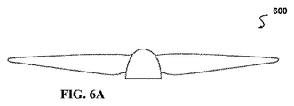
図6Aは、例示的なVTOL航空機用の例示的なプロペラ600の正面図である。図6Bは、図6Aの例示的なプロペラ600の上面図である。図6Cは、図6Aの例示的なプロペラ600の斜視図である。本開示のVTOL航空機に使用するプロペラ600のサイズは、既存のクワッドコプターおよびVTOL航空機よりも大幅に小さい。プロペラ600の角度は、所望の動きのために追加的なトルクを提供してVTOL航空機の操作性を高め、水平飛行時において効率性が悪い大きなプロペラを必要としない。プロペラ600は、垂直飛行に適応するように最適化されており、さらに水平飛行時の効率性も最大化する。ブレードの平面形状、ねじれ、および翼形は、専用の航空機プロペラの水平飛行効率に近い効率を維持するように調整されており、一方で、垂直飛行に必要なトルク要件を低減して、高い設計推力のマージンを維持する。
FIG. 6A is a front view of an
図7は、限定された垂直離着陸(VTOL)航空機700の正面図であり、胴体に近接して翼712、714の平面と平行な平面において傾斜したモータを有する。2つのさらなるモータと、これに対応するプロペラが、航空機700の反対側に存在する。限定的な航空機700は、2つのモータ702、704と、これに対応するプロペラ706、708を有しており、これらは翼712、714の平面と平行な平面においてのみ傾斜しており、すなわちモータ702、704の角度は、図1および5A−5Bに記載されてるような本明細書の例示的な実施例で開示されたモータの角度と垂直である。限定的な航空機700は、翼幅に対して垂直ではなく、翼幅に沿った平面の方向において傾斜したモータ702、704を有する。限定的な航空機700の翼幅に沿った平面におけるモータ702、704の角度は、この方向におけるモーメントを伴う上下の回転を促進するものではない。さらに、プロペラのダウンウォッシュが、垂直飛行中に、支持パイロン/フィンに逆方向モーメントおよび追加のダウンフォースを生成する。
FIG. 7 is a front view of a limited vertical takeoff and landing (VTOL)
限定的なVTOL航空機700は、また、モータ702、704を、重心の近くの胴体710に近接させて配置する。垂直飛行中に、横風により胴体710および/または翼712、714からの乱流716が増大する。縦方向への横風は、水平飛行からの移行時に失速空気を取り込むことになり、この場合に制御が最も重要になる。増大した乱流716は、胴体710に近接して配置されたモータ702、704に悪影響を与える。対照的に、本明細書に開示された例示的な実施例の航空機では、モータの両セットが、翼の端部の近くに配置されている。乱れていない空気の領域718、720が、本明細書に開示の例示的な実施例の翼の端部の近くに存在しており、長いモーメントアームと横風からの乱流の軽減を実現する。本明細書に開示された例示的な実施例では、翼面に垂直で翼端の近くにあるモータの角度は、支持パイロン/フィンの迎角を生じさせず、ベクトル推力によって作成された制御権限を損なうことなく、飛行に必要な力を減らす。
The
図8は、横風822において着陸801を行う例示的なVTOL航空機800の斜視図を示す。横風とは、航空機の移動方向に垂直な成分を有する風である。横風は、滑走路を使用する航空機の離着陸をより困難にする。VTOL航空機の垂直離陸時における横風の影響は、このような横風にさらされる翼と胴体の表面積が大きくなるために、拡大する。これらの表面は、プロペラの動作と効率に悪影響を与える乱流の領域を形成しうる。いくつかのVTOL航空機では、横風の影響に対抗するためにより大きなモータおよび/またはプロペラを必要としている。
FIG. 8 shows a perspective view of an
例示的なVTOL航空機800が、図8の軸に示すような負のx方向に着陸801を行っている。z方向および負のy方向の強い横風822が、航空機800を意図した着陸地点から離れるように促している。横風822が左翼804に衝突して、左翼804の下側に近接して乱流824の領域を生じさせる。横風822は胴体802にも衝突して、胴体802の底側に近接して乱流826の領域を生じさせる。横風822は右翼805にも衝突して、右翼805の下側に近接して乱流828の領域を生じさせる。
An
プロペラ814、816、818、820が、対応するウイングレット806、808、810、812によって翼804、805から離して配置されている。ウイングレット806、808、810、812は、翼804、805に対して垂直に示されているが、図5A−5Bのように翼に対して角度をつけて配置することもできる。さらに、プロペラ814、816、818、820は、翼804、805の前縁より上に配置されている。したがって、横風822は、下部右舷プロペラ820に影響する乱流828の領域のみを形成し、他のプロペラ814、816、818は、翼804、805および/または胴体802から発生する乱流の影響を受けない。一方で、プロペラ820はウイングレット812により翼から離されて、翼805の前縁よりも上に配置されているため、乱流または乱れた気流828の強度は、下部右舷プロペラ820に届くまでに著しく減少している。プロペラ818、814、816は、乱れていない気流の領域にある。したがって、横風の影響は、プロペラ814、816、818、820を翼804、805および胴体802から離して配置することにより解消されるため、航空機800は小さなモータおよび/またはプロペラを使用することができる。
上述の実施例の特定の特徴と態様の様々な組合せ、およびまたはサブコンビネーションが形成されてもよく、それらは本発明の範囲内にあるものと考えられる。したがって、開示された実施例の様々な特徴と態様を組み合わせて、または互いに置き換えることで、開示した発明の様々な態様を形成できることを理解すべきである。さらに、本発明の範囲は例として本明細書に開示されたものであり、上述に記載の特定の開示した実施例に限定すべきではない。 Various combinations, or sub-combinations, of the particular features and embodiments of the above-described examples may be formed and are believed to be within the scope of the present invention. Therefore, it should be understood that various aspects of the disclosed invention can be formed by combining or substituting the various features and aspects of the disclosed examples. Furthermore, the scope of the invention is disclosed herein by way of example and should not be limited to the particular disclosed examples described above.
Claims (20)
垂直離着陸(VTOL)航空機の上部左舷モータ、下部左舷モータ、上部右舷モータおよび下部右舷モータにほぼ等しい推進力を与えて垂直離陸を達成するステップであって、上部および下部の左舷モータが翼の第1の端部に配置され、上部および下部の右舷モータが前記翼の第1の端部から遠位にある翼の第2の端部に配置され、前記上部および下部の右舷モータが、前記翼の平面にほぼ垂直な第1の平面内で互いに離れるように角度がつけられ、前記上部および下部の左舷モータが、前記翼の平面にほぼ垂直な第2の平面内で互いに離れるように角度がつけられているステップと;
上部のモータの推力を上げるとともに下部のモータの推力を下げて、VTOL航空機の重心の周りに正味のモーメントを生成して、航空機を前方に回転させるステップと;
前記上部のモータの推力を上げるとともに前記下部のモータの推力を上げて、水平飛行を達成するステップであって、前記VTOL航空機の翼が水平飛行の初期の揚力を提供するステップと;を含むことを特徴とする方法。 The way:
Vertical Takeoff and Landing (VTOL) A step to achieve vertical takeoff by applying approximately equal propulsion to the upper port motor, lower port motor, upper starboard motor and lower starboard motor of the aircraft, where the upper and lower port motors are the first of the wings. The upper and lower starboard motors are located at one end, the upper and lower starboard motors are located at the second end of the wing distal to the first end of the wing, and the upper and lower starboard motors are located on the wing. Angled to separate from each other in a first plane approximately perpendicular to the plane of the wing, and angled so that the upper and lower port motors separate from each other in a second plane approximately perpendicular to the plane of the wing. With the attached steps;
Steps to increase the thrust of the upper motor and decrease the thrust of the lower motor to generate a net moment around the center of gravity of the VTOL aircraft and rotate the aircraft forward;
Includes a step of increasing the thrust of the upper motor and increasing the thrust of the lower motor to achieve level flight, wherein the wings of the VTOL aircraft provide the initial lift of level flight. A method characterized by.
Applications Claiming Priority (3)
| Application Number | Priority Date | Filing Date | Title |
|---|---|---|---|
| US201662345618P | 2016-06-03 | 2016-06-03 | |
| US62/345,618 | 2016-06-03 | ||
| PCT/US2017/035742 WO2017210595A2 (en) | 2016-06-03 | 2017-06-02 | Vertical take-off and landing (vtol) winged air vehicle with complementary angled rotors |
Publications (3)
| Publication Number | Publication Date |
|---|---|
| JP2019517412A JP2019517412A (en) | 2019-06-24 |
| JP2019517412A5 JP2019517412A5 (en) | 2020-07-09 |
| JP6825011B2 true JP6825011B2 (en) | 2021-02-03 |
Family
ID=60477933
Family Applications (1)
| Application Number | Title | Priority Date | Filing Date |
|---|---|---|---|
| JP2018562089A Active JP6825011B2 (en) | 2016-06-03 | 2017-06-02 | Vertical takeoff and landing winged aircraft with complementary angled rotors |
Country Status (9)
| Country | Link |
|---|---|
| US (4) | US10370095B2 (en) |
| EP (1) | EP3464064B1 (en) |
| JP (1) | JP6825011B2 (en) |
| KR (1) | KR102415393B1 (en) |
| CN (1) | CN109562828A (en) |
| AU (1) | AU2017272341B2 (en) |
| CA (1) | CA3026260A1 (en) |
| DK (1) | DK3464064T3 (en) |
| WO (1) | WO2017210595A2 (en) |
Families Citing this family (33)
| Publication number | Priority date | Publication date | Assignee | Title |
|---|---|---|---|---|
| US9550567B1 (en) | 2014-10-27 | 2017-01-24 | Amazon Technologies, Inc. | In-flight reconfigurable hybrid unmanned aerial vehicle |
| WO2016118230A1 (en) * | 2015-01-21 | 2016-07-28 | Sikorsky Aircraft Corporation | Flying wing vertical take-off and landing aircraft |
| US11001378B2 (en) | 2016-08-08 | 2021-05-11 | Jetoptera, Inc. | Configuration for vertical take-off and landing system for aerial vehicles |
| CA2996284A1 (en) | 2015-09-02 | 2017-04-20 | Jetoptera, Inc. | Fluidic propulsive system |
| US10464668B2 (en) | 2015-09-02 | 2019-11-05 | Jetoptera, Inc. | Configuration for vertical take-off and landing system for aerial vehicles |
| EP3386856B8 (en) * | 2015-12-07 | 2020-08-19 | Textron Systems Corporation | Uav with wing-plate assemblies providing efficient vertical takeoff and landing capability |
| AU2017272341B2 (en) | 2016-06-03 | 2023-01-19 | Aerovironment, Inc. | Vertical take-off and landing (VTOL) winged air vehicle with complementary angled rotors |
| US10633088B2 (en) * | 2016-07-01 | 2020-04-28 | Textron Innovations Inc. | Aerial imaging aircraft having attitude stability during translation |
| US11608173B2 (en) * | 2016-07-01 | 2023-03-21 | Textron Innovations Inc. | Aerial delivery systems using unmanned aircraft |
| US11027837B2 (en) * | 2016-07-01 | 2021-06-08 | Textron Innovations Inc. | Aircraft having thrust to weight dependent transitions |
| US10633087B2 (en) * | 2016-07-01 | 2020-04-28 | Textron Innovations Inc. | Aircraft having hover stability in inclined flight attitudes |
| DE102016218769A1 (en) * | 2016-09-28 | 2018-03-29 | Airbus Defence and Space GmbH | STARRFLÜGEL FLUGZEUG AND METHOD FOR OPERATING A STARRFLÜGELflugzeug |
| NL2017611B1 (en) * | 2016-10-12 | 2018-04-20 | Univ Delft Tech | Aerial vehicle with angularly displaced propulsion units |
| CN206155785U (en) * | 2016-11-08 | 2017-05-10 | 深圳市大疆创新科技有限公司 | Motor and have unmanned aerial vehicle of this motor |
| BR112019027805A2 (en) | 2017-06-27 | 2020-07-07 | Jetoptera, Inc. | configuration of vertical take-off and landing system for aerial vehicles |
| BR112020005719A2 (en) * | 2017-09-22 | 2020-10-06 | AMSL Innovations Pty Ltd | wing tilt actuation system for electric takeoff and vertical landing (vtol) aircraft |
| WO2019142014A1 (en) | 2018-01-18 | 2019-07-25 | Aerones, Sia | An electric drone glider arrangement |
| US20210371097A1 (en) * | 2018-01-30 | 2021-12-02 | Joseph Raymond RENTERIA | Rotatable thruster aircraft |
| IL261236B2 (en) * | 2018-08-19 | 2023-04-01 | Aerotor Unmanned Systems Ltd | Maneuverability improved airborne vehicle and a method implemented for this purpose |
| US11136115B2 (en) | 2018-06-20 | 2021-10-05 | Textron Innovations Inc. | Tilted propellers for enhanced distributed propulsion control authority |
| EP3587264B1 (en) * | 2018-06-28 | 2022-08-17 | Leonardo S.p.A. | Tail sitter |
| CN110654534A (en) * | 2018-06-29 | 2020-01-07 | 中光电智能机器人股份有限公司 | Rotorcraft |
| JP7207699B2 (en) * | 2018-10-10 | 2023-01-18 | ルーチェサーチ株式会社 | unmanned aerial vehicle |
| EP3702277B1 (en) * | 2019-02-27 | 2021-01-27 | AIRBUS HELICOPTERS DEUTSCHLAND GmbH | A multirotor aircraft that is adapted for vertical take-off and landing (vtol) |
| CN110271663A (en) * | 2019-04-30 | 2019-09-24 | 重庆大学 | Two sides separate type quadrotor and the compound unmanned plane of Flying-wing and its control method |
| US11279478B2 (en) * | 2019-06-18 | 2022-03-22 | Textron Innovations Inc. | Tilting closed-wing aircraft |
| CN113071668A (en) * | 2020-04-16 | 2021-07-06 | 灵遥机器人(深圳)有限责任公司 | Unmanned aerial vehicle |
| US20210339860A1 (en) * | 2020-04-30 | 2021-11-04 | Volansi, Inc. | Modular fixed vtol with line replaceable units |
| US11840351B2 (en) * | 2021-04-05 | 2023-12-12 | Beta Air, Llc | Aircraft for self-neutralizing flight |
| CN113716034A (en) * | 2021-08-31 | 2021-11-30 | 谷国强 | Double-rotor helicopter and fixed wing combined integrated manned aircraft |
| DE102021005473B3 (en) | 2021-11-05 | 2022-11-10 | Bundesrepublik Deutschland (Bundesamt für Ausrüstung, Informationstechnik und Nutzung der Bundeswehr) | Drone-carried weapon firing device |
| KR102549149B1 (en) | 2022-07-01 | 2023-06-30 | 주식회사 니나노컴퍼니 | Duct with improved crosswind stability and tail seater unmanned aerial vehicle using the duct |
| EP4339109A1 (en) * | 2022-09-16 | 2024-03-20 | Linking Drones SL | Vertical takeoff and landing aerial vehicles |
Family Cites Families (35)
| Publication number | Priority date | Publication date | Assignee | Title |
|---|---|---|---|---|
| US5419514A (en) * | 1993-11-15 | 1995-05-30 | Duncan; Terry A. | VTOL aircraft control method |
| US5765783A (en) * | 1994-03-04 | 1998-06-16 | The Boeing Company | Vertically launchable and recoverable winged aircraft |
| DE19745492B4 (en) * | 1997-10-15 | 2005-06-09 | Wobben, Aloys, Dipl.-Ing. | Vertical airplane |
| US20050178879A1 (en) * | 2004-01-15 | 2005-08-18 | Youbin Mao | VTOL tailsitter flying wing |
| US7159817B2 (en) | 2005-01-13 | 2007-01-09 | Vandermey Timothy | Vertical take-off and landing (VTOL) aircraft with distributed thrust and control |
| US8434710B2 (en) | 2007-11-21 | 2013-05-07 | Qinetiq Limited | Aircraft |
| US20100283253A1 (en) * | 2009-03-06 | 2010-11-11 | Bevirt Joeben | Tethered Airborne Power Generation System With Vertical Take-Off and Landing Capability |
| US20110127775A1 (en) * | 2009-05-20 | 2011-06-02 | Bevirt Joeben | Airborne Power Generation System With Modular Structural Elements |
| WO2010148373A1 (en) * | 2009-06-19 | 2010-12-23 | Joby Energy, Inc. | System and method for controlling a tethered flying craft using tether attachment point manipulation |
| US20110042508A1 (en) * | 2009-08-24 | 2011-02-24 | Bevirt Joeben | Controlled take-off and flight system using thrust differentials |
| US8800931B2 (en) * | 2010-03-24 | 2014-08-12 | Google Inc. | Planform configuration for stability of a powered kite and a system and method for use of same |
| EP2625098A4 (en) * | 2010-10-06 | 2018-01-17 | Donald Orval Shaw | Aircraft with wings and movable propellers |
| SG188691A1 (en) | 2011-09-27 | 2013-04-30 | Singapore Tech Aerospace Ltd | An unmanned aerial vehicle |
| WO2013104007A1 (en) * | 2012-01-02 | 2013-07-11 | Makani Power, Inc. | Motor pylons for a kite and airborne power generation system using same |
| CN103921933A (en) * | 2013-01-10 | 2014-07-16 | 深圳市大疆创新科技有限公司 | Deformation structure of air vehicle and micro air vehicle |
| AU2014293617A1 (en) * | 2013-05-03 | 2015-12-03 | Aerovironment, Inc. | Vertical takeoff and landing (VTOL) air vehicle |
| CN103287576A (en) * | 2013-05-24 | 2013-09-11 | 北京航空航天大学 | Tailless layout single tail seat type vertical take-off and landing aircraft |
| US9567088B2 (en) * | 2013-10-15 | 2017-02-14 | Swift Engineering, Inc. | Vertical take-off and landing aircraft |
| US9481457B2 (en) | 2014-04-02 | 2016-11-01 | Sikorsky Aircraft Corporation | Vertical take-off and landing aircraft with variable wing geometry |
| US9714087B2 (en) * | 2014-04-05 | 2017-07-25 | Hari Matsuda | Winged multi-rotor flying craft with payload accomodating shifting structure and automatic payload delivery |
| US9676488B2 (en) * | 2014-06-10 | 2017-06-13 | Sikorsky Aircraft Corporation | Dual dissimilar engines for an aircraft |
| US9601040B2 (en) | 2014-06-24 | 2017-03-21 | University Of Kansas | Flat-stock aerial vehicles and methods of use |
| NL2013252B1 (en) * | 2014-07-24 | 2016-09-09 | Atmos Uav B V | Aircraft with wing-borne flight mode and hover flight mode. |
| US9550567B1 (en) * | 2014-10-27 | 2017-01-24 | Amazon Technologies, Inc. | In-flight reconfigurable hybrid unmanned aerial vehicle |
| US9994313B2 (en) | 2014-11-26 | 2018-06-12 | XCraft Enterprises, LLC | High speed multi-rotor vertical takeoff and landing aircraft |
| DE102015006511A1 (en) * | 2015-05-26 | 2016-12-01 | Airbus Defence and Space GmbH | Vertical launching aircraft |
| US9908615B2 (en) * | 2015-10-26 | 2018-03-06 | Sikorsky Aircraft Corporation | Rotor blown wing aircraft including a rotor blown wing having at least one selectively controllable control surface and a method of controlling a rotor blown wing aircraft |
| AU2017272341B2 (en) * | 2016-06-03 | 2023-01-19 | Aerovironment, Inc. | Vertical take-off and landing (VTOL) winged air vehicle with complementary angled rotors |
| WO2018089583A1 (en) * | 2016-11-11 | 2018-05-17 | Aerovironment, Inc. | Extruded wing protection system and device |
| US20190009895A1 (en) * | 2017-05-08 | 2019-01-10 | Pinnacle Vista, LLC | Multi-copter lift body aircraft with tilt rotors |
| CN111819422A (en) * | 2018-01-29 | 2020-10-23 | 威罗门飞行公司 | Method and system for determining flight plan for vertical take-off and landing (VTOL) aircraft |
| EP3746361A4 (en) * | 2018-01-29 | 2021-10-06 | AeroVironment, Inc. | Methods and systems for energy-efficient take-offs and landings for vertical take-off and landing (vtol) aerial vehicles |
| US11155348B2 (en) * | 2018-01-30 | 2021-10-26 | Aerovironment, Inc. | Methods and systems for cloud-based management of images captured by aerial vehicles |
| IL261236B2 (en) * | 2018-08-19 | 2023-04-01 | Aerotor Unmanned Systems Ltd | Maneuverability improved airborne vehicle and a method implemented for this purpose |
| ES2933378T3 (en) * | 2018-04-27 | 2023-02-06 | Textron Systems Corp | Variable pitch rotor assembly for electrically actuated thrust vectored aircraft applications |
-
2017
- 2017-06-02 AU AU2017272341A patent/AU2017272341B2/en active Active
- 2017-06-02 KR KR1020187034404A patent/KR102415393B1/en active IP Right Grant
- 2017-06-02 EP EP17807595.8A patent/EP3464064B1/en active Active
- 2017-06-02 CN CN201780034238.8A patent/CN109562828A/en active Pending
- 2017-06-02 DK DK17807595.8T patent/DK3464064T3/en active
- 2017-06-02 CA CA3026260A patent/CA3026260A1/en active Pending
- 2017-06-02 JP JP2018562089A patent/JP6825011B2/en active Active
- 2017-06-02 WO PCT/US2017/035742 patent/WO2017210595A2/en unknown
- 2017-06-02 US US15/612,671 patent/US10370095B2/en active Active
-
2019
- 2019-06-26 US US16/453,308 patent/US11247772B2/en active Active
-
2022
- 2022-01-11 US US17/573,353 patent/US11851173B2/en active Active
-
2023
- 2023-11-06 US US18/387,383 patent/US20240076036A1/en active Pending
Also Published As
| Publication number | Publication date |
|---|---|
| EP3464064A2 (en) | 2019-04-10 |
| US20200047877A1 (en) | 2020-02-13 |
| US10370095B2 (en) | 2019-08-06 |
| DK3464064T3 (en) | 2022-12-19 |
| KR20190029517A (en) | 2019-03-20 |
| US20220297828A1 (en) | 2022-09-22 |
| EP3464064A4 (en) | 2020-02-19 |
| WO2017210595A2 (en) | 2017-12-07 |
| WO2017210595A3 (en) | 2018-01-11 |
| US11247772B2 (en) | 2022-02-15 |
| AU2017272341B2 (en) | 2023-01-19 |
| US11851173B2 (en) | 2023-12-26 |
| KR102415393B1 (en) | 2022-07-01 |
| EP3464064B1 (en) | 2022-11-16 |
| CA3026260A1 (en) | 2017-12-07 |
| AU2017272341A1 (en) | 2018-12-13 |
| CN109562828A (en) | 2019-04-02 |
| US20240076036A1 (en) | 2024-03-07 |
| US20180002003A1 (en) | 2018-01-04 |
| JP2019517412A (en) | 2019-06-24 |
Similar Documents
| Publication | Publication Date | Title |
|---|---|---|
| JP6825011B2 (en) | Vertical takeoff and landing winged aircraft with complementary angled rotors | |
| EP3188966B1 (en) | Tilt winged multi rotor | |
| CN106828915B (en) | Control method of high-speed aircraft with tilting propeller capable of vertically taking off and landing | |
| CN106184739B (en) | Flying equipment capable of vertically taking off | |
| JP2019517412A5 (en) | ||
| US20180215465A1 (en) | Rotatable thruster aircraft with separate lift thrusters | |
| EP2991897B1 (en) | Vertical takeoff and landing (vtol) air vehicle | |
| JP2022103349A (en) | Aircraft and method for flying aircraft | |
| US20140158815A1 (en) | Zero Transition Vertical Take-Off and Landing Aircraft | |
| KR101933003B1 (en) | A Vertical Take off and Landing Quadrotor Drone having A Fixed Wing | |
| JP2017528355A (en) | High performance vertical take-off and landing aircraft | |
| WO2018098993A1 (en) | Dual-axis vector servo steering device for propeller and vertical take-off and landing of unmanned aerial vehicle with fixed wings | |
| US20220169385A1 (en) | Tilt winged multi rotor | |
| EP3587264B1 (en) | Tail sitter | |
| US20200387170A1 (en) | System and method for enhanced altitude control of an autogyro | |
| CN108791816A (en) | A kind of tilting wing unmanned plane with complex pneumatic rudder face | |
| CN110770121B (en) | Aircraft with a flight control device | |
| CN112498678B (en) | Carrier-based vertical take-off and landing unmanned aerial vehicle and flight method | |
| CN210364377U (en) | Unconventional yawing unmanned aerial vehicle |
Legal Events
| Date | Code | Title | Description |
|---|---|---|---|
| A521 | Request for written amendment filed |
Free format text: JAPANESE INTERMEDIATE CODE: A523 Effective date: 20200529 |
|
| A621 | Written request for application examination |
Free format text: JAPANESE INTERMEDIATE CODE: A621 Effective date: 20200529 |
|
| A871 | Explanation of circumstances concerning accelerated examination |
Free format text: JAPANESE INTERMEDIATE CODE: A871 Effective date: 20200529 |
|
| A975 | Report on accelerated examination |
Free format text: JAPANESE INTERMEDIATE CODE: A971005 Effective date: 20200619 |
|
| A131 | Notification of reasons for refusal |
Free format text: JAPANESE INTERMEDIATE CODE: A131 Effective date: 20200623 |
|
| A601 | Written request for extension of time |
Free format text: JAPANESE INTERMEDIATE CODE: A601 Effective date: 20200923 |
|
| TRDD | Decision of grant or rejection written | ||
| A01 | Written decision to grant a patent or to grant a registration (utility model) |
Free format text: JAPANESE INTERMEDIATE CODE: A01 Effective date: 20201215 |
|
| A61 | First payment of annual fees (during grant procedure) |
Free format text: JAPANESE INTERMEDIATE CODE: A61 Effective date: 20210113 |
|
| R150 | Certificate of patent or registration of utility model |
Ref document number: 6825011 Country of ref document: JP Free format text: JAPANESE INTERMEDIATE CODE: R150 |
|
| R250 | Receipt of annual fees |
Free format text: JAPANESE INTERMEDIATE CODE: R250 |