JP6822816B2 - Construction system and construction method using mobile robots in pipes - Google Patents
Construction system and construction method using mobile robots in pipes Download PDFInfo
- Publication number
- JP6822816B2 JP6822816B2 JP2016205233A JP2016205233A JP6822816B2 JP 6822816 B2 JP6822816 B2 JP 6822816B2 JP 2016205233 A JP2016205233 A JP 2016205233A JP 2016205233 A JP2016205233 A JP 2016205233A JP 6822816 B2 JP6822816 B2 JP 6822816B2
- Authority
- JP
- Japan
- Prior art keywords
- pipe
- mobile robot
- construction
- target range
- unit
- Prior art date
- Legal status (The legal status is an assumption and is not a legal conclusion. Google has not performed a legal analysis and makes no representation as to the accuracy of the status listed.)
- Active
Links
- 238000010276 construction Methods 0.000 title claims description 330
- 238000000034 method Methods 0.000 claims description 73
- 238000012545 processing Methods 0.000 claims description 73
- 230000008569 process Effects 0.000 claims description 58
- 238000001514 detection method Methods 0.000 claims description 55
- 239000003550 marker Substances 0.000 claims description 40
- 230000008602 contraction Effects 0.000 claims description 39
- 230000001678 irradiating effect Effects 0.000 claims description 33
- 210000002569 neuron Anatomy 0.000 claims description 27
- 238000010801 machine learning Methods 0.000 claims description 26
- 238000005259 measurement Methods 0.000 claims description 25
- 238000013528 artificial neural network Methods 0.000 claims description 21
- 238000003384 imaging method Methods 0.000 claims description 19
- 230000007246 mechanism Effects 0.000 claims description 17
- 230000001133 acceleration Effects 0.000 claims description 16
- 238000013461 design Methods 0.000 claims description 16
- 230000004807 localization Effects 0.000 claims description 14
- 238000000926 separation method Methods 0.000 claims description 14
- 238000013135 deep learning Methods 0.000 claims description 12
- 230000004044 response Effects 0.000 claims description 9
- 230000008859 change Effects 0.000 claims description 6
- 238000009434 installation Methods 0.000 claims description 3
- 238000012546 transfer Methods 0.000 claims 1
- 239000000463 material Substances 0.000 description 14
- 239000011248 coating agent Substances 0.000 description 13
- 238000000576 coating method Methods 0.000 description 13
- 238000004891 communication Methods 0.000 description 11
- 238000001816 cooling Methods 0.000 description 5
- JEIPFZHSYJVQDO-UHFFFAOYSA-N iron(III) oxide Inorganic materials O=[Fe]O[Fe]=O JEIPFZHSYJVQDO-UHFFFAOYSA-N 0.000 description 5
- 239000010953 base metal Substances 0.000 description 4
- 238000012407 engineering method Methods 0.000 description 4
- 238000010408 sweeping Methods 0.000 description 4
- 239000013598 vector Substances 0.000 description 4
- 230000009471 action Effects 0.000 description 3
- 238000006073 displacement reaction Methods 0.000 description 3
- 238000007667 floating Methods 0.000 description 3
- 230000014509 gene expression Effects 0.000 description 3
- 230000007274 generation of a signal involved in cell-cell signaling Effects 0.000 description 3
- 238000012423 maintenance Methods 0.000 description 3
- 238000003825 pressing Methods 0.000 description 3
- 230000002194 synthesizing effect Effects 0.000 description 3
- 238000004140 cleaning Methods 0.000 description 2
- 230000006866 deterioration Effects 0.000 description 2
- 230000003628 erosive effect Effects 0.000 description 2
- 230000006870 function Effects 0.000 description 2
- 230000007257 malfunction Effects 0.000 description 2
- 230000003287 optical effect Effects 0.000 description 2
- 230000003647 oxidation Effects 0.000 description 2
- 238000007254 oxidation reaction Methods 0.000 description 2
- 238000010183 spectrum analysis Methods 0.000 description 2
- 229910001220 stainless steel Inorganic materials 0.000 description 2
- 239000010935 stainless steel Substances 0.000 description 2
- 230000000007 visual effect Effects 0.000 description 2
- 238000003466 welding Methods 0.000 description 2
- 238000013459 approach Methods 0.000 description 1
- 238000004364 calculation method Methods 0.000 description 1
- 239000000470 constituent Substances 0.000 description 1
- 238000012937 correction Methods 0.000 description 1
- 230000008878 coupling Effects 0.000 description 1
- 238000010168 coupling process Methods 0.000 description 1
- 238000005859 coupling reaction Methods 0.000 description 1
- 238000010586 diagram Methods 0.000 description 1
- 239000000428 dust Substances 0.000 description 1
- 230000000694 effects Effects 0.000 description 1
- 238000011835 investigation Methods 0.000 description 1
- 238000002360 preparation method Methods 0.000 description 1
- 238000011084 recovery Methods 0.000 description 1
- 238000007790 scraping Methods 0.000 description 1
- 230000008054 signal transmission Effects 0.000 description 1
- 230000005236 sound signal Effects 0.000 description 1
Images


Description
本開示は、移動ロボットにより配管の内表面に対する施工を行うための配管内の施工システムおよび配管内の施工方法に関係する。 The present disclosure relates to a construction system in a pipe and a construction method in the pipe for performing construction on the inner surface of the pipe by a mobile robot.
プラント等の構造物を構成する配管のメンテナンスのために配管内表面に対して施工作業が必要となる場合がある。一例として、長期にわたって稼働しているプラントを構成する配管の内表面に錆や粉塵等の異物がスケールとして堆積すると、このスケールがプラント運転中に剥離して後段の装置類に達し、当該装置類の故障や破損を引き起こす場合がある。そこで、当該スケールの事前除去作業等のような配管内のメンテナンス作業が必要となるが、このような作業は、配管の長手方向に沿って配管内を移動しながら配管内の施工を行う移動ロボットを備えた施工システムを使用して行われることがある。 Construction work may be required on the inner surface of pipes for maintenance of pipes that make up structures such as plants. As an example, when foreign matter such as rust or dust accumulates as scale on the inner surface of the piping that constitutes a plant that has been operating for a long period of time, this scale peels off during plant operation and reaches the equipment in the subsequent stage, and the equipment concerned. May cause malfunction or damage. Therefore, maintenance work inside the pipe, such as pre-removal work of the scale, is required, and such work is a mobile robot that performs construction inside the pipe while moving inside the pipe along the longitudinal direction of the pipe. It may be done using a construction system equipped with.
以下の特許文献1〜3は、上記のような配管内のメンテナンス作業として配管内表面に堆積したスケールや塗膜をレーザ光の照射により除去するためのレーザ照射部を備え、管路内を移動しながら管路内の施工を行う移動ロボットを開示している。特に、特許文献3では、反射ミラーを動かしてレーザ照射方向を制御すると共に、配管内に堆積した錆の厚みや程度を含む配管内の表面状態をセンサで検知し、配管内の表面状態に応じてレーザ照射条件を制御する技術が開示されている。
The following
しかしながら、特許文献1〜3記載の発明では、配管内を移動中の移動ロボットがレーザ照射部からのレーザ光の照射により配管内表面に堆積したスケールや塗膜を除去する場合、以下のような問題が生じる。すなわち、移動ロボットのレーザ照射部からのレーザ照射によって配管内表面が高温となり、配管内を移動中の移動ロボットが備える機器類やセンサ類が熱による動作不良や故障を引き起こすおそれがある。例えば、配管内表面の表面状態を検出するセンサや配管内の空間認識を行うセンサを当該移動ロボットが備えている場合、レーザ照射によって配管内表面に生じる高熱により、当該センサの計測精度の劣化や故障が生じ、施工作業を正しく行えない恐れがある。
However, in the inventions described in
上記問題点に鑑み、本発明に係る幾つかの実施形態では、移動ロボットが配管内を移動しながら配管内表面にレーザ照射を行うことで配管内に高熱が生じても、当該移動ロボットが備える機器類やセンサ類が当該高熱によって検出精度低下や故障を起こしにくい配管内の施工システムを得ることを目的とする。 In view of the above problems, in some embodiments according to the present invention, even if high heat is generated in the pipe by irradiating the inner surface of the pipe with laser while the mobile robot moves in the pipe, the mobile robot is provided. The purpose is to obtain a construction system in the piping that is unlikely to cause deterioration of detection accuracy or failure of equipment and sensors due to the high heat.
(1)本発明の幾つかの実施形態に係る移動ロボットによる配管内施工システムは、
配管の長手方向に予め設定された施工対象範囲にわたり、前記配管の内表面を走査することで前記配管の内表面の状態を検出するための表面状態センサと、
前記配管のうち長手方向における施工対象範囲において、前記表面状態センサを前記配管の内部において前記長手方向に移動させるように構成された第1移動ロボットと、
前記配管の前記内表面に向けてレーザ光を照射するためのレーザ照射部と、
前記施工対象範囲において、前記レーザ照射部を前記配管の内部において前記長手方向に移動させるように構成された第2移動ロボットと、
前記レーザ照射部及び前記第2移動ロボットを制御するよう構成された制御部と、を備え、
前記制御部は、
前記表面状態センサの走査が完了した前記施工対象範囲についての前記表面状態センサの検出結果に基づいて、前記施工対象範囲における前記配管の前記内表面の位置座標を示す3次元データを取得した上で、前記レーザ光の照射エリアが前記3次元データ上において特定された3次元マップを取得するためのマップ取得部と、
前記3次元マップに基づいて、前記施工対象範囲内における前記照射エリアに対して選択的に前記レーザ光が照射されるよう、前記レーザ照射部及び前記第2移動ロボットに指令を送るための指令生成部と、を含むことを特徴とする。
(1) The in-pipe construction system using a mobile robot according to some embodiments of the present invention is
A surface condition sensor for detecting the state of the inner surface of the pipe by scanning the inner surface of the pipe over a preset construction target range in the longitudinal direction of the pipe.
A first mobile robot configured to move the surface condition sensor in the longitudinal direction inside the pipe in a construction target range in the longitudinal direction of the pipe.
A laser irradiation unit for irradiating the inner surface of the pipe with a laser beam,
A second mobile robot configured to move the laser irradiation unit in the longitudinal direction inside the pipe in the construction target range.
A control unit configured to control the laser irradiation unit and the second mobile robot is provided.
The control unit
Based on the detection result of the surface condition sensor for the construction target range in which the scanning of the surface condition sensor is completed, three-dimensional data indicating the position coordinates of the inner surface of the pipe in the construction target range is acquired. , A map acquisition unit for acquiring a three-dimensional map in which the irradiation area of the laser beam is specified on the three-dimensional data.
Based on the three-dimensional map, command generation for sending a command to the laser irradiation unit and the second mobile robot so that the laser beam is selectively irradiated to the irradiation area within the construction target range. It is characterized by including a part and.
上記(1)の構成によれば、第1移動ロボットを配管内の長手方向に移動させて表面状態センサの走査が完了した施工対象範囲について表面状態センサの検出結果に基づくレーザ光照射エリアが特定された3次元マップを用いて、レーザ照射部によるレーザ光の照射を行うようにしたので、表面状態センサによる走査タイミングをレーザ光照射タイミングよりも充分前にずらすことができる。すなわち、上記(1)の構成によれば、レーザ光照射エリアがレーザ照射によって高温となる前に、表面状態センサを搭載した第1移動ロボットが当該エリアを通過することになり、表面状態センサの高熱による検出精度低下や故障が生じにくい。よって、配管の内表面状態からレーザ光の照射エリアを正しく特定し、当該正しく特定された照射エリアに対して選択的にレーザ光が照射されるようにすることができる。 According to the configuration of (1) above, the laser light irradiation area based on the detection result of the surface condition sensor is specified for the construction target range in which the scanning of the surface condition sensor is completed by moving the first mobile robot in the longitudinal direction in the pipe. Since the laser irradiation unit irradiates the laser beam using the generated three-dimensional map, the scanning timing by the surface state sensor can be shifted sufficiently before the laser beam irradiation timing. That is, according to the configuration (1) above, the first mobile robot equipped with the surface state sensor passes through the area before the laser light irradiation area becomes hot due to the laser irradiation, and the surface state sensor Detection accuracy is less likely to decrease or failure due to high heat. Therefore, the irradiation area of the laser beam can be correctly specified from the inner surface state of the pipe, and the laser beam can be selectively irradiated to the correctly specified irradiation area.
(2)例示的な一実施形態では、上記(1)の構成において、前記マップ取得部は、前記表面状態センサの走査が完了した前記施工対象範囲についての前記表面状態センサの検出結果に基づいて、
前記施工対象範囲における前記配管の前記内表面の空間形状を表す3次元データを算出し、
前記レーザ光を照射すべき一つ以上の照射エリアの位置と範囲をそれぞれ表す一つ以上のデータが前記3次元データ上に重畳されて成る3次元マップを取得する
ように構成されたことを特徴とする。
(2) In one exemplary embodiment, in the configuration of (1) above, the map acquisition unit is based on the detection result of the surface condition sensor for the construction target range in which the scanning of the surface condition sensor is completed. ,
Three-dimensional data representing the spatial shape of the inner surface of the pipe in the construction target range is calculated.
It is characterized in that one or more data representing the positions and ranges of one or more irradiation areas to be irradiated with the laser beam are superimposed on the three-dimensional data to acquire a three-dimensional map. And.
上記(2)の構成では、初期段階において、施工対象範囲における配管の内表面の空間形状を表す3次元データを算出する。さらに上記(2)の構成では、初期段階に続く第2段階以降において、レーザ光を照射すべき複数の照射エリアの位置と範囲をそれぞれ表す複数のデータを当該3次元データ上に順次重ね合わせるようにして3次元マップを段階的に生成してゆく。その結果、上記(2)の構成によれば、3次元データに対して複数の照射エリアの各々に関するジオメトリック情報をインクリメンタルな方法でそれぞれ追加してゆくことで、3次元マップを効率的に合成することができる。 In the configuration of (2) above, in the initial stage, three-dimensional data representing the spatial shape of the inner surface of the pipe in the construction target range is calculated. Further, in the configuration of the above (2), in the second and subsequent stages following the initial stage, a plurality of data representing the positions and ranges of the plurality of irradiation areas to be irradiated with the laser beam are sequentially superimposed on the three-dimensional data. And the 3D map is generated step by step. As a result, according to the configuration of (2) above, the 3D map is efficiently synthesized by adding the geometric information about each of the plurality of irradiation areas to the 3D data by an incremental method. can do.
(3)例示的な一実施形態では、上記(1)または(2)の構成において、前記第1移動ロボットと前記第2移動ロボットは単一の移動ロボットを形成し、前記移動ロボットは、前記施工対象範囲を前記配管の長手方向に沿った第1方向に延びる往路と、前記施工対象範囲を前記第1方向とは逆方向に延びる復路とを含む移動経路上において移動するように構成され、
前記マップ取得部は、前記移動ロボットが前記往路を移動する間における前記表面状態センサの検出結果に基づいて前記照射エリアが特定された前記3次元マップを取得するように構成され、
前記指令生成部は、前記3次元マップを取得した後、前記移動ロボットが前記復路の移動を開始し、前記移動ロボットが前記復路にて前記施工対象範囲全体を移動する間に、前記3次元マップに基づいて、前記施工対象範囲内における前記照射エリアに対して選択的に前記レーザ光が照射されるよう、前記レーザ照射部及び前記第2移動ロボットとしての前記移動ロボットに指令を送る
ように構成されたことを特徴とする。
(3) In one exemplary embodiment, in the configuration of (1) or (2), the first mobile robot and the second mobile robot form a single mobile robot, and the mobile robot is the mobile robot. It is configured to move on a movement path including an outward path extending the construction target range in the first direction along the longitudinal direction of the pipe and a return path extending the construction target range in the direction opposite to the first direction.
The map acquisition unit is configured to acquire the three-dimensional map in which the irradiation area is specified based on the detection result of the surface state sensor while the mobile robot moves on the outbound route.
After acquiring the three-dimensional map, the command generation unit starts the movement of the return path, and while the mobile robot moves the entire construction target range on the return path, the three-dimensional map. Based on the above, a command is sent to the laser irradiation unit and the mobile robot as the second mobile robot so that the laser beam is selectively irradiated to the irradiation area within the construction target range. It is characterized by being done.
上記(3)の構成では、施工対象範囲についての配管の内表面の状態検出と、施工対象範囲についての配管の内表面へのレーザ照射と、を単一の移動ロボットの一回の往復移動により実行することができる。そのため、上記(3)の構成によれば、上記(1)または(2)の構成と同様の作用効果に加え、配管内の施工対象範囲全体に対する施工作業を短時間で完了させることができる。また、上記(3)の構成によれば、第1移動ロボットと第2移動ロボットを単一の移動ロボットとして形成することで、配管内の施工システムの構造をコンパクトにすることができる。 In the configuration of (3) above, the state of the inner surface of the pipe for the construction target range is detected, and the laser irradiation for the inner surface of the pipe for the construction target range is performed by one reciprocating movement of a single mobile robot. Can be executed. Therefore, according to the configuration of the above (3), in addition to the same action and effect as the configuration of the above (1) or (2), the construction work for the entire construction target range in the pipe can be completed in a short time. Further, according to the configuration of (3) above, by forming the first mobile robot and the second mobile robot as a single mobile robot, the structure of the construction system in the pipe can be made compact.
(4)例示的な一実施形態では、上記(1)または(2)の構成において、前記第1移動ロボットと前記第2移動ロボットは、前記施工対象範囲全体を移動する別個の移動ロボットとして形成され、
前記マップ取得部は、前記第1移動ロボットが前記施工対象範囲全体を移動する間における前記表面状態センサの検出結果に基づいて前記照射エリアが特定された前記3次元マップを取得するように構成され、
前記指令生成部は、前記3次元マップを取得した後、前記第2移動ロボットが前記施工対象範囲内にて移動を開始し、前記第2移動ロボットが前記施工対象範囲全体を移動する間に、前記3次元マップに基づいて、前記施工対象範囲内における前記照射エリアに対して選択的に前記レーザ光が照射されるよう、前記レーザ照射部及び前記第2移動ロボットに指令を送る
ように構成されたことを特徴とする。
(4) In one exemplary embodiment, in the configuration of (1) or (2), the first mobile robot and the second mobile robot are formed as separate mobile robots that move the entire construction target range. Being done
The map acquisition unit is configured to acquire the three-dimensional map in which the irradiation area is specified based on the detection result of the surface state sensor while the first mobile robot moves over the entire construction target range. ,
After acquiring the three-dimensional map, the command generation unit starts moving within the construction target range, and while the second mobile robot moves the entire construction target range, Based on the three-dimensional map, it is configured to send a command to the laser irradiation unit and the second mobile robot so that the laser beam is selectively irradiated to the irradiation area within the construction target range. It is characterized by that.
上記(4)の構成では、施工対象範囲にわたる表面状態センサの走査を完了するために表面状態センサを移動させる第1移動ロボットと施工対象範囲にわたって配管内にレーザ照射を行うレーザ照射部を移動させる第2移動ロボットは別個の移動ロボットとして形成される。従って、上記(4)の構成では、第1移動ロボットによる作業と第2移動ロボットによる作業を時間的および/または空間的に分離して行うようにすれば、配管内においてレーザ照射部のレーザ照射によって生じる高熱の影響を表面状態センサが受けないようにすることができる。その結果、上記(4)の構成によれば、表面状態センサの高熱による検出精度低下や故障を一層効果的に防止することができる。 In the configuration (4) above, the first mobile robot that moves the surface condition sensor to complete the scanning of the surface condition sensor over the construction target range and the laser irradiation unit that performs laser irradiation over the construction target range are moved. The second mobile robot is formed as a separate mobile robot. Therefore, in the configuration of (4) above, if the work by the first mobile robot and the work by the second mobile robot are separated temporally and / or spatially, the laser irradiation of the laser irradiation unit in the pipe is performed. It is possible to prevent the surface condition sensor from being affected by the high heat generated by the surface condition sensor. As a result, according to the configuration of (4) above, it is possible to more effectively prevent deterioration of detection accuracy and failure due to high heat of the surface state sensor.
(5)例示的な一実施形態では、上記(1)〜(4)の構成において、前記レーザ照射部は、前記レーザ光の照射方向が回転するように前記配管内の周方向に沿って回動自在に構成されたノズル部を含み、
前記制御部は、前記配管内の長手方向に沿った各位置にて、前記配管の周方向において前記照射エリアが占める角度範囲に応じて、前記配管の前記長手方向に沿った前記第2移動ロボットの走行速度を制御するように構成されたことを特徴とする。
(5) In one exemplary embodiment, in the configurations (1) to (4) above, the laser irradiation unit rotates along the circumferential direction in the pipe so that the irradiation direction of the laser beam rotates. Includes a freely configured nozzle
The control unit is the second mobile robot along the longitudinal direction of the pipe at each position in the pipe along the longitudinal direction according to the angle range occupied by the irradiation area in the circumferential direction of the pipe. It is characterized in that it is configured to control the traveling speed of.
配管の周方向においてレーザ照射を行うべき照射エリアが占める角度範囲が広い軸方向位置(配管の長手方向における位置)では、第2移動ロボット上のレーザ照射部は、配管内の周方向に沿ったレーザ照射の掃引を広範囲にわたって重点的に行う必要がある。逆に、照射エリアが占める角度範囲が狭い軸方向位置では、第2移動ロボット上のレーザ照射部は、レーザ照射の掃引を短時間で済ませることができる。 At the axial position (position in the longitudinal direction of the pipe) where the irradiation area to which the laser irradiation should be performed in the circumferential direction of the pipe occupies a wide angular range, the laser irradiation portion on the second mobile robot is along the circumferential direction in the pipe. It is necessary to focus on a wide range of laser irradiation sweeps. On the contrary, in the axial position where the angle range occupied by the irradiation area is narrow, the laser irradiation unit on the second mobile robot can finish sweeping the laser irradiation in a short time.
そこで、上記(5)の構成では、配管内の長手方向に沿った各位置(軸方向位置)において、配管の周方向においてレーザ照射を行うべき照射エリアが占める角度範囲に応じて配管の長手方向に沿った第2移動ロボットの走行速度を制御するようにしている。よって、施工対象範囲内における照射エリアについてレーザ照射を確実に行いながら、レーザ照射作業を効率的に行うことができる。 Therefore, in the configuration (5) above, at each position (axial position) along the longitudinal direction in the pipe, the longitudinal direction of the pipe is determined according to the angle range occupied by the irradiation area to which the laser irradiation should be performed in the circumferential direction of the pipe. The traveling speed of the second mobile robot is controlled according to the above. Therefore, it is possible to efficiently perform the laser irradiation work while reliably performing the laser irradiation in the irradiation area within the construction target range.
(6)例示的な一実施形態では、上記(1)〜(5)の構成において、前記制御部は、前記表面状態センサが検出した前記配管内の表面状態に基づいて前記レーザ光の照射条件を制御する
ように構成されたことを特徴とする。
(6) In one exemplary embodiment, in the configurations (1) to (5), the control unit performs the laser light irradiation condition based on the surface condition in the pipe detected by the surface condition sensor. It is characterized in that it is configured to control.
上記(6)の構成によれば、配管の内表面にレーザ照射を行うことによる施工作業の種別(酸化物スケールの除去、洗浄、塗膜除去など)、配管の内表面の表面状態(例えば、酸化物スケールの付着面積、酸化物スケールの厚さ、塗膜の浮き上がり、塗膜の厚み等)に応じてレーザ光の照射条件を制御しながら施工対象範囲にわたってレーザ照射による施工作業を行うことができる。その結果、上記(6)の構成によれば、配管内の各施工箇所において、レーザ照射を必要な出力で必要な時間だけ行うことで、配管の肉厚をレーザ照射により必要以上に削り取ってしまうことを防止することができる。 According to the configuration of (6) above, the type of construction work (removal of oxide scale, cleaning, coating film removal, etc.) by irradiating the inner surface of the pipe with a laser, and the surface condition of the inner surface of the pipe (for example, It is possible to perform the construction work by laser irradiation over the construction target range while controlling the irradiation conditions of the laser beam according to the adhesion area of the oxide scale, the thickness of the oxide scale, the floating of the coating film, the thickness of the coating film, etc.). it can. As a result, according to the configuration of (6) above, the wall thickness of the pipe is scraped off more than necessary by laser irradiation by performing laser irradiation at the required output and for the required time at each construction site in the pipe. Can be prevented.
(7)例示的な一実施形態では、上記(1)〜(6)の構成において、前記第1移動ロボットによって前記施工対象範囲にて前記配管内を移動可能に構成され、走査信号波を照射して前記配管内の3次元空間を走査することで、前記走査信号波の照射源から前記配管内の空間を構成する複数の点までのそれぞれの距離と方向を表す第1点群データを前記配管内の空間形状を表す空間計測情報として取得するための第1の3次元スキャナをさらに備え、
前記制御部は、前記第1点群データに基づいて生成された前記3次元マップを取得するように構成された
ことを特徴とする。
(7) In one exemplary embodiment, in the configurations (1) to (6), the first mobile robot is configured to be movable in the pipe within the construction target range and irradiates a scanning signal wave. By scanning the three-dimensional space in the pipe, the first point group data representing the distance and direction from the irradiation source of the scanning signal wave to the plurality of points constituting the space in the pipe is obtained. Further equipped with a first 3D scanner for acquiring as spatial measurement information representing the spatial shape in the pipe.
The control unit is characterized in that it is configured to acquire the three-dimensional map generated based on the first point cloud data.
上記(7)の構成によれば、3次元スキャナで配管内部空間を構成する各点までの距離を測定して得られる点群データに基づいて、配管内の3次元マップを生成可能としているので、配管内の表面形状も含めた配管内の空間形状の認識を高精度に行うことができる。 According to the configuration of (7) above, it is possible to generate a three-dimensional map in the pipe based on the point cloud data obtained by measuring the distances to each point constituting the pipe internal space with a three-dimensional scanner. , It is possible to recognize the spatial shape in the pipe including the surface shape in the pipe with high accuracy.
(8)例示的な一実施形態では、上記(1)〜(7)の構成において、前記配管内における前記第2移動ロボットの自己位置を表す自己位置情報を取得するための自己位置取得部をさらに備え、
前記制御部は、前記自己位置取得部で取得された前記自己位置が前記3次元マップ上の前記照射エリアに含まれるか否かを判定し、前記自己位置が前記照射エリア内に含まれる場合に前記レーザ光の照射を行うように前記レーザ照射部を制御するよう構成されたことを特徴とする。
(8) In one exemplary embodiment, in the configurations (1) to (7) above, a self-position acquisition unit for acquiring self-position information representing the self-position of the second mobile robot in the pipe is provided. Further prepare,
The control unit determines whether or not the self-position acquired by the self-position acquisition unit is included in the irradiation area on the three-dimensional map, and when the self-position is included in the irradiation area. It is characterized in that the laser irradiation unit is controlled so as to irradiate the laser beam.
上記(8)の構成によれば、自己位置が照射エリア内に含まれる場合にレーザ光の照射を行うことで、配管内のレーザ照射が必要な場所でのみレーザ照射を行うようにすることが可能である。その結果、上記(8)の構成によれば、配管内のレーザ照射が必要でない場所で配管の肉厚をレーザ照射により無駄に削り取ってしまうことを防止することができる。 According to the configuration of (8) above, by irradiating the laser beam when the self-position is included in the irradiation area, the laser irradiation can be performed only in the place where the laser irradiation is required in the pipe. It is possible. As a result, according to the configuration of (8) above, it is possible to prevent the wall thickness of the pipe from being unnecessarily scraped off by laser irradiation in a place where laser irradiation is not required in the pipe.
(9)例示的な一実施形態では、上記(8)の構成において、前記第2移動ロボットによって前記施工対象範囲にて前記配管内を移動可能に構成され、走査信号波を照射して前記配管内の3次元空間を走査することで、前記配管内の空間を構成する複数の点までのそれぞれの距離を表す第2点群データを前記配管内の空間形状を表す空間計測情報として取得するための第2の3次元スキャナをさらに備え、
前記自己位置情報は、前記第2の3次元スキャナによって取得した前記第2点群データを、前記配管の形状設計時に得られた配管形状設計情報と照合することにより算出されることを特徴とする。
(9) In one exemplary embodiment, in the configuration of (8) above, the second mobile robot is configured to be movable in the pipe within the construction target range, and the pipe is irradiated with a scanning signal wave. By scanning the three-dimensional space inside, the second point group data representing the respective distances to the plurality of points constituting the space in the pipe is acquired as the space measurement information representing the space shape in the pipe. Also equipped with a second 3D scanner
The self-position information is calculated by collating the second point cloud data acquired by the second three-dimensional scanner with the pipe shape design information obtained at the time of designing the shape of the pipe. ..
上記(9)の構成によれば、配管形状設計情報に点群データを照合することで、3次元スキャナ(即ち、配管内の移動ロボット)の現在の軸方向位置だけでなく、3次元スキャナ(即ち配管内の移動ロボット)の管軸周り(周方向)の姿勢をも特定することができる。よって、配管内において移動ロボットが移動する際に、配管内の移動ロボットの姿勢が変化しても、このことを考慮した自己位置情報を取得することができ、レーザ光の照射エリアを高精度に特定することができる。 According to the configuration of (9) above, by collating the point cloud data with the pipe shape design information, not only the current axial position of the 3D scanner (that is, the moving robot in the pipe) but also the 3D scanner (that is, the 3D scanner (that is, the moving robot in the pipe)) That is, the posture around the pipe axis (circumferential direction) of the mobile robot in the pipe can also be specified. Therefore, when the mobile robot moves in the pipe, even if the posture of the mobile robot in the pipe changes, it is possible to acquire self-position information in consideration of this, and the laser beam irradiation area can be made highly accurate. Can be identified.
(10)例示的な一実施形態では、上記(8)の構成において、前記3次元マップは、前記施工対象範囲において前記配管に形成されたマーカーの位置情報を含み、
前記マーカーを検出するためのマーカー検出器と、
前記第2移動ロボットによって前記施工対象範囲にて前記配管内を移動可能に構成され、走査信号波を照射して前記配管内の3次元空間を走査することで、前記配管内の空間を構成する複数の点までのそれぞれの距離を表す第2点群データを前記配管内の空間形状を表す空間計測情報として取得するための第2の3次元スキャナと、をさらに備え、
前記自己位置情報は、前記第2点群データ上に重ね合された前記マーカーの検出位置と、前記3次元マップに含まれる前記マーカーの前記位置情報と、を照合することにより算出されることを特徴とする。
(10) In one exemplary embodiment, in the configuration of (8) above, the three-dimensional map includes position information of a marker formed on the pipe in the construction target range.
A marker detector for detecting the marker and
The second mobile robot is configured to be movable in the pipe within the construction target range, and the space in the pipe is configured by irradiating a scanning signal wave and scanning the three-dimensional space in the pipe. Further provided with a second three-dimensional scanner for acquiring second point cloud data representing each distance to a plurality of points as spatial measurement information representing the spatial shape in the pipe.
The self-position information is calculated by collating the detection position of the marker superimposed on the second point cloud data with the position information of the marker included in the three-dimensional map. It is a feature.
上記(10)の構成によれば、第2の3次元スキャナによって取得した第2点群データ上に重ね合されたマーカーの検出位置と、3次元マップに含まれるマーカーの位置情報と、を照合することで、マーカーの位置を基準として3次元マップとの関係で自己位置を精度良く特定することができる。 According to the configuration of (10) above, the detection position of the marker superimposed on the second point cloud data acquired by the second 3D scanner and the position information of the marker included in the 3D map are collated. By doing so, the self-position can be accurately specified in relation to the three-dimensional map with reference to the position of the marker.
(11)例示的な一実施形態では、上記(8)の構成において、前記第2移動ロボットによって前記施工対象範囲にて前記配管内を移動可能に構成されたジャイロ・センサおよび加速度センサをさらに備え、
前記自己位置情報は、前記ジャイロ・センサおよび前記加速度センサの少なくとも一方の計測結果を少なくとも使用して算出されることを特徴とする。
(11) In one exemplary embodiment, the configuration of (8) further includes a gyro sensor and an acceleration sensor configured to be movable in the pipe within the construction target range by the second mobile robot. ,
The self-position information is calculated by using at least the measurement results of at least one of the gyro sensor and the acceleration sensor.
上記(11)の構成によれば、ジャイロ・センサおよび加速度センサから計測値として得られる少量のデータに対して簡単な演算処理を施すことで、ジャイロ・センサおよび加速度センサを搭載した第2移動ロボットの現在の自己位置を特定することができる。その結果、上記(11)の構成によれば、簡単な演算処理を実行するだけで自己位置を短時間で精度良く特定することができる。 According to the configuration of (11) above, a second mobile robot equipped with a gyro sensor and an acceleration sensor is provided by performing simple arithmetic processing on a small amount of data obtained as a measured value from the gyro sensor and the acceleration sensor. Can identify the current self-position of. As a result, according to the configuration of (11) above, the self-position can be accurately specified in a short time only by executing a simple arithmetic process.
(12)例示的な一実施形態では、上記(8)の構成において、前記制御部からの鳴動指令に応じて音波を発する複数の音源が設けられ、
前記第1移動ロボットと前記第2移動ロボットの少なくともいずれか一方である移動ロボットは、音波センサアレイをさらに備え、
前記音波センサアレイは、前記音波を観測する音波観測手段を2つ以上含み、観測された前記音波から音源信号を出力するように構成され、
前記制御部から前記鳴動指令のタイミングを受け取った前記自己位置取得部は、
前記鳴動指令のタイミングおよび前記音波センサアレイからの前記音源信号に基づいて複数の前記音源のそれぞれの位置から見た前記音波センサアレイの相対位置を推定し、
複数の前記音源の設置位置を前記音波センサアレイの相対位置と照合することにより、前記自己位置情報を算出する、
ようにさらに構成されることを特徴とする。
(12) In one exemplary embodiment, in the configuration of (8) above, a plurality of sound sources that emit sound waves in response to a ringing command from the control unit are provided.
The mobile robot, which is at least one of the first mobile robot and the second mobile robot, further includes a sound wave sensor array.
The sound wave sensor array includes two or more sound wave observation means for observing the sound wave, and is configured to output a sound wave signal from the observed sound wave.
The self-position acquisition unit that has received the timing of the ringing command from the control unit
Based on the timing of the ringing command and the sound source signal from the sound wave sensor array, the relative position of the sound wave sensor array as seen from each position of the plurality of sound sources is estimated.
The self-position information is calculated by collating the installation positions of the plurality of sound sources with the relative positions of the sound wave sensor array.
It is characterized in that it is further configured.
上記(12)の構成によれば、配管内からの剥離物により移動ロボットに汚れが付着し、移動ロボットの光学機器や撮影装置の視界が遮られた場合であっても、配管内に設けた複数の音源からの音波を頼りに移動ロボットの自己位置を検出することが可能となる。同様に、走査信号波の反射波を移動ロボット側で検出する反射波検出センサに汚れが付着し、走査信号波による配管内の3次元スキャンが困難となった場合でも、音源からの音波を頼りに移動ロボットの自己位置を検出することが可能となる。また、上記(12)の構成において、複数の音源から音を発するタイミングや音の種類などを制御部からの鳴動指令により適切に制御することで、音源からの音波に基づく移動ロボットの自己位置の検出を精度良く行うことができる。 According to the configuration of (12) above, even when the mobile robot is contaminated by a detached object from the inside of the pipe and the field of view of the optical device or the photographing device of the mobile robot is obstructed, the robot is provided in the pipe. It is possible to detect the self-position of the mobile robot by relying on the sound waves from a plurality of sound sources. Similarly, even if the reflected wave detection sensor that detects the reflected wave of the scanning signal wave on the mobile robot side becomes dirty and it becomes difficult to scan the inside of the pipe with the scanning signal wave in three dimensions, the sound wave from the sound source is relied on. It is possible to detect the self-position of the mobile robot. Further, in the configuration (12) above, the timing of sound emission from a plurality of sound sources, the type of sound, and the like are appropriately controlled by a ringing command from the control unit, so that the self-position of the mobile robot based on the sound waves from the sound sources can be determined. The detection can be performed with high accuracy.
(13)例示的な一実施形態では、上記(12)の構成において、前記自己位置取得部は、
前記音波センサアレイから多重チャネル音源信号である前記音源信号を受け取り、前記鳴動指令のタイミング、前記多重チャネル音源信号および前記2つ以上の音波観測手段の間の位置関係に基づいて音源分離処理と音源定位処理を実行する音響信号空間処理部と、
前記音源分離処理と前記音源定位処理の実行結果に基づいて前記音源のそれぞれの位置と前記音波センサアレイの位置との間の相対的な位置関係を推定する音源位置推定部と、
を備えることを特徴とする。
(13) In one exemplary embodiment, in the configuration of (12) above, the self-position acquisition unit is
The sound source signal, which is a multi-channel sound source signal, is received from the sound wave sensor array, and the sound source separation process and the sound source are performed based on the timing of the ringing command, the positional relationship between the multi-channel sound source signal and the two or more sound wave observation means. An acoustic signal space processing unit that executes localization processing,
A sound source position estimation unit that estimates the relative positional relationship between each position of the sound source and the position of the sound wave sensor array based on the execution results of the sound source separation process and the sound source localization process.
It is characterized by having.
上記(13)の構成では、音波センサアレイ内の複数の音波観測手段によって得られる多重チャネル音源信号を、鳴動指令のタイミングおよび複数の音波観測手段の間の位置関係と組み合わせて用いることで音源分離処理と音源定位処理を実行する。その結果、複数の音波観測手段によって得られる多重チャネル音源信号のみを単独で用いる場合と比べて、音波の到来方向や音源までの距離などを表現可能な音響空間情報(音の空間的な情報)を精度良く算出することができる。また、多重チャネル音源信号のみならず、鳴動指令のタイミングおよび複数の音波観測手段の間の位置関係を補助的な情報として併用することで、音源分離処理と音源定位処理を簡単かつ効率的に実行することが可能となる。 In the configuration (13) above, the sound source separation is performed by using the multi-channel sound source signal obtained by the plurality of sound wave observation means in the sound wave sensor array in combination with the timing of the ringing command and the positional relationship between the plurality of sound wave observation means. Execute processing and sound source localization processing. As a result, acoustic spatial information (spatial information of sound) that can express the arrival direction of sound waves and the distance to the sound source, as compared with the case where only the multi-channel sound source signals obtained by a plurality of sound wave observation means are used alone. Can be calculated accurately. Moreover, by using not only the multi-channel sound source signal but also the timing of the ringing command and the positional relationship between the plurality of sound wave observation means as auxiliary information, the sound source separation process and the sound source localization process can be executed easily and efficiently. It becomes possible to do.
(14)例示的な一実施形態では、上記(1)〜(13)の構成において、前記表面状態センサは、前記配管の内表面を撮影した画像を前記制御部に出力する撮像装置を含み、
前記制御部は、
前記画像から画像認識によって前記3次元マップが示す前記照射エリアにおける内表面状態を示す内表面状態情報を生成し、
前記内表面状態情報に基づいて、前記レーザ照射部への指令を生成する
ように構成されることを特徴とする。
(14) In one exemplary embodiment, in the configurations (1) to (13) above, the surface state sensor includes an imaging device that outputs an image of the inner surface of the pipe to the control unit.
The control unit
From the image, image recognition is used to generate inner surface state information indicating the inner surface state in the irradiation area indicated by the three-dimensional map.
It is characterized in that it is configured to generate a command to the laser irradiation unit based on the inner surface state information.
従来、レーザ光の照射により母材表面に対する施工作業を手作業で行っていた際には、作業者が目視により視認した母材表面の表面状態に基づいて各施工箇所に対するレーザ光の照射条件を調整することにより母材の表面状態に応じた適切な施工を行っていた。そこで、上記(12)の構成では、目視により視認した母材表面の表面状態に対応する機械的に認識処理可能な情報として、配管の内表面を撮像装置により撮影した画像を取得し、当該画像から画像認識によって配管内の照射エリアにおける内表面状態を示す内表面状態情報を生成している。その結果、上記(12)によれば、当該内表面状態情報に基づいて、レーザ照射部への指令を生成することで、従来から手動で行われていた母材表面状態に応じたレーザ照射条件の調整操作を配管内の施工作業のために自動化することができる。 Conventionally, when the construction work on the base material surface is manually performed by irradiating the laser beam, the laser beam irradiation conditions for each construction site are determined based on the surface condition of the base metal surface visually visually recognized by the operator. By making adjustments, appropriate construction was performed according to the surface condition of the base metal. Therefore, in the configuration of (12) above, an image of the inner surface of the pipe taken by an imaging device is acquired as information that can be mechanically recognized and processed corresponding to the surface state of the surface of the base material visually visually recognized, and the image is taken. The inner surface condition information indicating the inner surface condition in the irradiation area in the pipe is generated from the image recognition. As a result, according to the above (12), by generating a command to the laser irradiation unit based on the inner surface state information, the laser irradiation condition according to the surface state of the base material, which has been manually performed conventionally. Adjustment operations can be automated for construction work in the piping.
(15)例示的な一実施形態では、上記(14)の構成において、前記制御部は、前記配管の内表面を撮影した画像から前記3次元マップが示す前記照射エリアについての前記内表面状態情報を生成する際に、
外部から入力された教師信号に従って前記画像認識の精度を向上させる機械学習プロセスを実行し、
前記機械学習プロセスの実行によって得られた学習結果を用いて、前記画像認識を実行する
ように構成されたことを特徴とする。
(15) In one exemplary embodiment, in the configuration of (14) above, the control unit has the inner surface state information about the irradiation area shown by the three-dimensional map from an image obtained by photographing the inner surface of the pipe. When generating
A machine learning process that improves the accuracy of the image recognition is executed according to the teacher signal input from the outside.
It is characterized in that the image recognition is executed by using the learning result obtained by executing the machine learning process.
上記(15)の構成では、照射エリアを撮影した画像から配管内の照射エリアにおける内表面状態を示す内表面状態情報を生成するための画像認識は、機械学習プロセスの実行によって得られた学習結果を用いて実行される。その際、この機械学習プロセスは、外部から入力された教師信号に従って当該画像認識の精度を向上させるように実行される。従って、上記(13)の構成によれば、教師信号に従って実行される機械学習プロセスにより画像認識実行主体としての制御部をトレーニングし、それにより上述した内表面状態を必要な認識精度で認識できるように上述した画像認識の精度を向上させることができる。 In the configuration of (15) above, the image recognition for generating the inner surface state information indicating the inner surface state in the irradiation area in the pipe from the photographed image of the irradiation area is the learning result obtained by executing the machine learning process. Is executed using. At that time, this machine learning process is executed so as to improve the accuracy of the image recognition according to the teacher signal input from the outside. Therefore, according to the configuration of (13) above, the control unit as the image recognition execution subject is trained by the machine learning process executed according to the teacher signal, whereby the above-mentioned inner surface state can be recognized with the required recognition accuracy. The accuracy of image recognition described above can be improved.
(16)例示的な一実施形態では、上記(15)の構成において、前記制御部は、前記配管の内表面を撮影した画像から前記3次元マップが示す前記照射エリアについての前記内表面状態情報を生成する際に、
前記配管の内表面を撮影した画像を初期入力とし、前記教師信号によってニューロン出力の誤差が補正されるニューラルネットワークを使用してディープ・ラーニングを実行することで前記機械学習プロセスを実行し、
前記ディープ・ラーニングの実行によって得られた学習結果を用いて、前記画像認識を実行する
ように構成されたことを特徴とする。
(16) In one exemplary embodiment, in the configuration of (15) above, the control unit has the inner surface state information about the irradiation area shown by the three-dimensional map from an image obtained by photographing the inner surface of the pipe. When generating
The machine learning process is executed by performing deep learning using a neural network in which an image obtained by photographing the inner surface of the pipe is used as an initial input and the error of the neuron output is corrected by the teacher signal.
It is characterized in that it is configured to execute the image recognition by using the learning result obtained by executing the deep learning.
上記(16)の構成では、上述した画像認識の精度を向上させるために、教師信号に従って実行される機械学習プロセスとして教師信号によってニューロン出力の誤差が補正されるニューラルネットワークを使用したディープ・ラーニングを実行する。従って、上記(16)の構成によれば、上述した画像認識の精度を向上させるための機械学習プロセスにおいて、分光スペクトル解析や色情報分析などの工学的手法に従って配管の内表面を撮影した画像から特徴量を抽出する必要がない。そのため、上記(16)の構成によれば、照射エリアを撮影した画像から内表面状態情報を生成する際に、画像からの工学的手法に基づく特徴量抽出が困難な画像認識を行わなくてはならない場合であっても、内表面状態を必要な認識精度で認識可能な画像認識を容易に実現することができる。 In the configuration of (16) above, in order to improve the accuracy of the image recognition described above, deep learning using a neural network in which the error of the neuron output is corrected by the teacher signal is performed as a machine learning process executed according to the teacher signal. Execute. Therefore, according to the configuration of (16) above, in the machine learning process for improving the accuracy of image recognition described above, from an image obtained by photographing the inner surface of the pipe according to an engineering method such as spectroscopic spectrum analysis or color information analysis. There is no need to extract features. Therefore, according to the configuration of (16) above, when generating the inner surface state information from the image obtained by capturing the irradiation area, it is necessary to perform image recognition in which it is difficult to extract the feature amount from the image based on the engineering method. Even if this is not the case, image recognition that can recognize the inner surface state with the required recognition accuracy can be easily realized.
(17)本発明の幾つかの実施形態に係る配管内の施工システムは、
配管内を前記配管の長手方向に沿って移動するように構成された移動ロボットと、
前記移動ロボットの進行方向における前方にて前記移動ロボットに搭載され、前記配管の内表面の状態を検出するための表面状態センサと、
前記進行方向における後方にて前記移動ロボットに搭載され、前記配管の前記内表面に向けてレーザ光を照射するためのレーザ照射部と、
前記レーザ照射部及び前記移動ロボットを制御するよう構成された制御部と、を備え、
前記制御部は、
施工対象範囲にわたって前記移動ロボットの前記進行方向に沿って並ぶ一つ以上の位置の各々に前記移動ロボットが位置するたびに、前記表面状態センサの検出結果に基づいて前記レーザ照射部を制御するように構成されている。
(17) The construction system in the pipe according to some embodiments of the present invention is
A mobile robot configured to move in the pipe along the longitudinal direction of the pipe, and
A surface condition sensor mounted on the mobile robot in front of the mobile robot in the traveling direction for detecting the state of the inner surface of the pipe,
A laser irradiation unit mounted on the mobile robot behind in the traveling direction and for irradiating the laser beam toward the inner surface of the pipe.
The laser irradiation unit and the control unit configured to control the mobile robot are provided.
The control unit
Each time the mobile robot is positioned at each of one or more positions arranged along the traveling direction of the mobile robot over the construction target range, the laser irradiation unit is controlled based on the detection result of the surface state sensor. It is configured in.
上記(17)の構成では、配管の内表面の状態を検出するための表面状態センサが移動ロボットの進行方向における前方に搭載され、配管の内表面に向けてレーザ光を照射するためのレーザ照射部が移動ロボットの進行方向における後方に搭載されている。従って、上記(17)の構成では、施工対象範囲内での移動ロボットが進行方向に向かって移動中に、表面状態センサにより配管内の表面状態を検出する工程とレーザ照射部が配管の内表面にレーザ照射を行う工程を同時に実行しても、レーザ照射対象である照射エリアがレーザ照射によって高温化する前に、当該エリアを表面状態センサが通過することになる。その結果、上記(17)の構成では、表面状態センサを高熱に曝すことなく、配管内の表面状態を検出する工程と配管の内表面にレーザ照射を行う工程を単一の移動ロボットを用いて同時に実行することで、配管内の施工作業を短時間で終わらせることができる。 In the configuration (17) above, a surface condition sensor for detecting the condition of the inner surface of the pipe is mounted in front of the mobile robot in the traveling direction, and laser irradiation for irradiating the inner surface of the pipe with laser light is performed. The unit is mounted rearward in the direction of travel of the mobile robot. Therefore, in the configuration (17) above, while the moving robot within the construction target range is moving in the traveling direction, the step of detecting the surface state in the pipe by the surface state sensor and the laser irradiation unit are the inner surface of the pipe. Even if the steps of performing laser irradiation are simultaneously executed, the surface state sensor passes through the irradiation area to be laser-irradiated before the temperature rises due to the laser irradiation. As a result, in the configuration of the above (17), a single mobile robot is used to perform a step of detecting the surface state in the pipe and a step of irradiating the inner surface of the pipe with laser without exposing the surface state sensor to high heat. By executing at the same time, the construction work in the pipe can be completed in a short time.
(18)例示的な一実施形態では、上記(17)の構成において、前記移動ロボット(第1移動ロボットと前記第2移動ロボットの少なくともいずれか一方である移動ロボット)は、前記配管の長手方向に沿って延在する長尺形状に形成される本体部を備え、
前記表面状態センサは、前記本体部の周方向の異なる位置に複数配置され、広角レンズをそれぞれ有する複数の撮像ユニットを含んで構成され、
複数の前記撮像ユニットがそれぞれ有する前記広角レンズの各々は、前記配管内の周方向に沿って部分的に重複する複数の角度範囲の各々を視野に含むことで、前記配管の内表面を全周方向にわたる像を撮影可能に構成されており、
前記制御部は、
前記複数の撮像ユニットが前記配管内を撮影した画像から前記配管の内表面状態を示す内表面状態情報を生成し、
前記内表面状態情報に基づいて、前記レーザ照射を行うべき前記配管内のエリアの位置と範囲を識別しながら前記レーザ照射部への制御指令を生成する
ように構成されることを特徴とする。
(18) In one exemplary embodiment, in the configuration of (17) above, the mobile robot (a mobile robot that is at least one of the first mobile robot and the second mobile robot) is in the longitudinal direction of the pipe. It has a main body that is formed in a long shape that extends along the
A plurality of the surface state sensors are arranged at different positions in the circumferential direction of the main body portion, and include a plurality of imaging units each having a wide-angle lens.
Each of the wide-angle lenses possessed by the plurality of imaging units includes each of a plurality of angular ranges partially overlapping along the circumferential direction in the pipe in the field of view, thereby covering the entire inner surface of the pipe. It is configured to be able to take images over the direction,
The control unit
The plurality of imaging units generate inner surface state information indicating the inner surface state of the pipe from images taken inside the pipe.
It is characterized in that it is configured to generate a control command to the laser irradiation unit while identifying the position and range of the area in the pipe to which the laser irradiation should be performed based on the inner surface state information.
上記(18)の構成では、移動ロボットが配管内を移動中に移動ロボットの進行方向前方に配置された複数の広角レンズにより配管の内表面の全周方向にわたって移動ロボットの直近前方から直近後方までの範囲をカバーする画像を撮影することができる。また、これらの広角レンズによる配管内の撮影と同時並行して移動ロボットの進行方向後方に配置されたレーザ照射部からレーザ照射を行うことができる。従って、上記(18)の構成によれば、表面状態センサにより配管内を走査することで配管内の3次元マップを生成する必要なしに、レーザ照射を行うべき配管内のエリアの位置と範囲を識別することが可能となる。さらに、上記(18)の構成によれば、移動ロボットの自己位置を検出する必要なしに、レーザ照射を行うべき配管内のエリアの位置と範囲を識別することも可能となる。 In the configuration (18) above, while the mobile robot is moving in the pipe, a plurality of wide-angle lenses arranged in front of the moving robot in the traveling direction are used to cover the entire inner surface of the pipe from the immediate front to the immediate rear. It is possible to take an image that covers the range of. Further, the laser irradiation can be performed from the laser irradiation unit arranged behind the moving direction of the mobile robot in parallel with the photographing in the pipe by these wide-angle lenses. Therefore, according to the configuration of (18) above, the position and range of the area in the pipe to be laser-irradiated can be determined without the need to generate a three-dimensional map in the pipe by scanning the inside of the pipe with the surface state sensor. It becomes possible to identify. Further, according to the configuration (18) above, it is possible to identify the position and range of the area in the pipe to be irradiated with the laser without having to detect the self-position of the mobile robot.
(19)例示的な一実施形態では、上記(18)の構成において、前記制御部は、前記施工対象範囲における前記移動ロボットの前記進行方向への前記配管内での移動中、
前記表面状態センサの検出結果に基づいて、前記配管の内表面のうち照射エリアを特定し、
前記照射エリアに対して選択的に前記レーザ光が照射されるよう前記レーザ照射部を制御する
ように構成されたことを特徴とする。
(19) In one exemplary embodiment, in the configuration of (18) above, the control unit is moving in the pipe in the traveling direction of the mobile robot in the construction target range.
Based on the detection result of the surface condition sensor, the irradiation area on the inner surface of the pipe is specified.
It is characterized in that the laser irradiation unit is controlled so that the laser beam is selectively irradiated to the irradiation area.
上記(19)の構成によれば、照射エリアに対して選択的にレーザ光が照射されるようレーザ照射部を制御することで、配管内のレーザ照射が必要な場所でのみレーザ照射を行うようにすることが可能である。その結果、上記(19)の構成によれば、上記(18)と同様の原理により単一の移動ロボットを用いて配管内の施工作業を短時間で終わらせることができるのに加え、配管内のレーザ照射が必要でない場所で配管の肉厚をレーザ照射により無駄に削り取ってしまうことを防止することができる。 According to the configuration of (19) above, by controlling the laser irradiation unit so that the laser beam is selectively irradiated to the irradiation area, the laser irradiation is performed only in the place where the laser irradiation is required in the pipe. It is possible to. As a result, according to the configuration of the above (19), in addition to being able to finish the construction work in the pipe in a short time by using a single mobile robot by the same principle as the above (18), the inside of the pipe It is possible to prevent the wall thickness of the pipe from being unnecessarily scraped off by laser irradiation in a place where laser irradiation is not required.
(20)例示的な一実施形態では、上記(1)〜(19)の構成において、前記移動ロボット(第1移動ロボットと前記第2移動ロボットの少なくともいずれか一方である移動ロボット)は、
前記配管の長手方向に沿って延在する長尺形状に形成された本体部と、
前記本体部の周方向の異なる位置に複数配置され、配管の内表面上を走行可能に構成された複数のクローラ型走行体と、
前記本体部の周方向の異なる位置に複数配置され、前記本体部に対して前記クローラ型走行体を前記配管の径方向に沿って拡縮可能に支持するように構成された伸縮機構をそれぞれ有する複数の腕部と、
を含んで構成されることを特徴とする。
(20) In one exemplary embodiment, in the configurations (1) to (19), the mobile robot (a mobile robot that is at least one of the first mobile robot and the second mobile robot) is
A main body formed in a long shape extending along the longitudinal direction of the pipe, and
A plurality of crawler-type traveling bodies arranged at different positions in the circumferential direction of the main body portion and configured to be able to travel on the inner surface of the pipe.
A plurality of telescopic mechanisms are arranged at different positions in the circumferential direction of the main body portion, and each has a telescopic mechanism configured to support the crawler type traveling body with respect to the main body portion so as to be expandable and contractible along the radial direction of the pipe. Arms and
It is characterized in that it is composed including.
上記(20)の構成によれば、移動ロボットの本体部の周方向に沿った複数の位置にそれぞれ設置された複数のクローラ型走行体を複数の腕部がそれぞれ備える伸縮機構によって径方向に沿って拡縮することができることで、以下の技術的利点を得られる。 According to the configuration of (20) above, a plurality of crawler-type traveling bodies installed at a plurality of positions along the circumferential direction of the main body of the mobile robot are provided along the radial direction by a telescopic mechanism provided by the plurality of arms. The following technical advantages can be obtained by being able to scale the robot.
例えば、移動ロボットが配管の内表面と接触したり、配管の屈曲部において擱座したりして配管内で立ち往生し、移動ロボットが操作不能となった場合を考える。この場合、複数のクローラ型走行体をそれぞれ支持する複数の腕部を収縮させることができるので、移動ロボットを配管内から回収する際に、本体部から突き出した腕部とクローラ型走行体が邪魔にならないようにすることができる。その結果、上記(20)の構成によれば、移動ロボットが配管内で立ち往生したことにより配管内で移動ロボットを操作不能となった場合でも、移動ロボットの回収を円滑に行うことができる。 For example, consider a case where a mobile robot comes into contact with the inner surface of a pipe or sits down at a bent portion of the pipe and gets stuck in the pipe, making the mobile robot inoperable. In this case, since a plurality of arms supporting each of the plurality of crawler-type traveling bodies can be contracted, the arms protruding from the main body and the crawler-type traveling body interfere with the recovery of the mobile robot from the pipe. Can be prevented from becoming. As a result, according to the configuration (20) above, even if the mobile robot becomes inoperable in the pipe due to being stuck in the pipe, the mobile robot can be smoothly collected.
(21)例示的な一実施形態では、上記(20)の構成において、複数の前記腕部がそれぞれ有する前記伸縮機構は、
前記配管の径方向に沿って付勢されたバネにより前記クローラ型走行体を前記配管の内表面に押し付けるように伸縮するバネ部材と、
前記配管の径方向に沿った伸縮動作により、前記本体部に対する前記腕部の伸縮量を変化させるように構成されたシリンダ装置と、
前記制御部から受信した伸縮指示信号に応じて前記シリンダ装置を駆動することにより、前記腕部の伸縮量を制御するように構成された伸縮量調整部と、
を備えることを特徴とする。
(21) In one exemplary embodiment, in the configuration of (20) above, the telescopic mechanism of each of the plurality of arms is
A spring member that expands and contracts so as to press the crawler type traveling body against the inner surface of the pipe by a spring urged along the radial direction of the pipe.
A cylinder device configured to change the amount of expansion and contraction of the arm portion with respect to the main body portion by the expansion and contraction operation along the radial direction of the pipe.
An expansion / contraction amount adjusting unit configured to control the expansion / contraction amount of the arm portion by driving the cylinder device in response to an expansion / contraction instruction signal received from the control unit.
It is characterized by having.
この実施形態によれば、配管内で移動ロボットが擱座したことを移動ロボットに搭載されたセンサ等によりユーザが検知した場合、制御部は、伸縮量調整部に伸縮指示信号を送信することができる。その際、制御部は、複数のクローラ型走行体をそれぞれ支持する複数の腕部を径方向の内側に収縮させるための伸縮量を伸縮量調整部に指示することで、当該複数の腕部を収縮させることができる。従って、移動ロボットの擱座を検知した際に、制御部からの遠隔操作により本体部から突き出した腕部を収縮させ、移動ロボットを配管内から回収する際に、腕部とクローラ型走行体が邪魔にならないようにすることができる。 According to this embodiment, when the user detects that the mobile robot is seated in the pipe by a sensor or the like mounted on the mobile robot, the control unit can transmit an expansion / contraction instruction signal to the expansion / contraction amount adjusting unit. .. At that time, the control unit instructs the expansion / contraction amount adjusting unit to contract the plurality of arms that support the plurality of crawler-type traveling bodies inward in the radial direction, thereby causing the plurality of arms to contract. Can be contracted. Therefore, when the mobile robot's seat is detected, the arm protruding from the main body is contracted by remote control from the control unit, and when the mobile robot is recovered from the pipe, the arm and the crawler type traveling body interfere with each other. Can be prevented from becoming.
(22)例示的な一実施形態では、上記(21)の構成において、前記制御部は、前記伸縮量調整部に対して与える伸縮指示信号を前記配管の内表面の形状に応じて適応的に選択することにより、前記配管の内表面に対して前記クローラ型走行体の走行に必要な接地力を確保するように前記シリンダ装置を制御するようにさらに構成されることを特徴とする。 (22) In one exemplary embodiment, in the configuration of (21) above, the control unit adaptively sends an expansion / contraction instruction signal given to the expansion / contraction amount adjusting unit according to the shape of the inner surface of the pipe. By selecting, it is further configured to control the cylinder device so as to secure a ground contact force required for traveling of the crawler type traveling body with respect to the inner surface of the pipe.
例えば、配管の形状が直角に曲がった屈曲部を有するT字型である場合、当該屈曲部は、配管内の直管部とは異なる特異な内壁面形状を有する。そのため、移動ロボットが当該屈曲部を円滑に通り抜けるためには、当該内壁面形状に合わせて腕部の伸縮動作を適切に行うことが必要となる。そこで、上記(22)の構成では、複数の腕部の伸縮機構をそれぞれ構成するバネ部材とシリンダ装置の働きにより、配管の内表面に対し、クローラ型走行体の走行に必要な接地力を確保するようにしている。具体的には、移動ロボットが配管内の屈曲部を通過する際、バネ部材とシリンダ装置の働きにより、以下のようにして必要な接地力が確保される。すなわち、屈曲部における特異な内壁面形状に合わせてクローラ型走行体を配管の内表面に押し付けることで、配管の内表面に対してクローラ型走行体の走行に必要な接地力を維持し続けることが可能となる。 For example, when the shape of the pipe is a T-shape having a bent portion bent at a right angle, the bent portion has a peculiar inner wall surface shape different from that of the straight pipe portion in the pipe. Therefore, in order for the mobile robot to smoothly pass through the bent portion, it is necessary to appropriately expand and contract the arm portion according to the shape of the inner wall surface. Therefore, in the configuration of (22) above, the ground contact force required for traveling of the crawler type traveling body is secured with respect to the inner surface of the pipe by the action of the spring member and the cylinder device that respectively constitute the expansion / contraction mechanism of the plurality of arms. I try to do it. Specifically, when the mobile robot passes through the bent portion in the pipe, the necessary ground contact force is secured as follows by the action of the spring member and the cylinder device. That is, by pressing the crawler type traveling body against the inner surface of the pipe according to the peculiar inner wall surface shape at the bent portion, the ground contact force required for the running of the crawler type traveling body is maintained against the inner surface of the pipe. Is possible.
(23)本発明の幾つかの実施形態に係る配管内施工方法は、
配管のうち長手方向における施工対象範囲において、表面状態センサを前記配管の内部において前記長手方向に移動させながら、前記配管の内表面の状態を検出するステップと、
前記表面状態センサの走査が完了した前記施工対象範囲についての前記表面状態センサの検出結果に基づいて、前記前記施工対象範囲における前記配管の前記内表面の位置座標を示す3次元データを取得した上で、前記3次元データ上においてレーザ光の照射エリアが特定された3次元マップを取得するステップと、
前記施工対象範囲にわたって前記配管内の前記長手方向に沿って並ぶ一つ以上の位置の各々において、レーザ照射部を制御することで、前記配管の前記内表面に向けた前記レーザ光の照射を制御するステップと、
を備え、
前記レーザ光の照射を制御するステップでは、前記3次元マップに基づいて、前記施工対象範囲内における前記照射エリアに対して選択的に前記レーザ光が照射されるよう、前記レーザ照射部を制御することを特徴とする。
(23) The in-pipe construction method according to some embodiments of the present invention is
A step of detecting the state of the inner surface of the pipe while moving the surface condition sensor in the longitudinal direction inside the pipe in the construction target range in the longitudinal direction of the pipe.
Based on the detection result of the surface condition sensor for the construction target range in which the scanning of the surface condition sensor is completed, three-dimensional data indicating the position coordinates of the inner surface of the pipe in the construction target range is acquired. Then, the step of acquiring the three-dimensional map in which the irradiation area of the laser beam is specified on the three-dimensional data, and
By controlling the laser irradiation unit at each of one or more positions in the pipe along the longitudinal direction over the construction target range, the irradiation of the laser light toward the inner surface of the pipe is controlled. Steps to do and
With
In the step of controlling the irradiation of the laser beam, the laser irradiation unit is controlled so that the laser beam is selectively irradiated to the irradiation area within the construction target range based on the three-dimensional map. It is characterized by that.
上記(23)の構成によれば、第1移動ロボットを配管内の長手方向に移動させて表面状態センサの走査が完了した施工対象範囲について表面状態センサの検出結果に基づくレーザ光照射エリアが特定された3次元マップを用いて、レーザ照射部によるレーザ光の照射を行うようにしたので、表面状態センサによる走査タイミングをレーザ光照射タイミングよりも充分前にずらすことができる。すなわち、上記(23)の構成によれば、レーザ光照射エリアがレーザ照射によって高温となる前に、表面状態センサを搭載した第1移動ロボットが当該エリアを通過することになり、表面状態センサの高熱による検出精度低下や故障が生じにくい。よって、配管の内表面状態からレーザ光の照射エリアを正しく特定し、当該正しく特定された照射エリアに対して選択的にレーザ光が照射されるようにすることができる。 According to the configuration of (23) above, the laser light irradiation area based on the detection result of the surface condition sensor is specified for the construction target range in which the scanning of the surface condition sensor is completed by moving the first mobile robot in the longitudinal direction in the pipe. Since the laser irradiation unit irradiates the laser beam using the three-dimensional map, the scanning timing by the surface state sensor can be shifted sufficiently before the laser beam irradiation timing. That is, according to the configuration of (23) above, the first mobile robot equipped with the surface state sensor passes through the area before the laser light irradiation area becomes hot due to the laser irradiation, and the surface state sensor Detection accuracy is less likely to decrease or failure due to high heat. Therefore, the irradiation area of the laser beam can be correctly specified from the inner surface state of the pipe, and the laser beam can be selectively irradiated to the correctly specified irradiation area.
(24)本発明の幾つかの実施形態に係る配管内施工方法は、
移動ロボットと、前記移動ロボットの進行方向における前方にて前記移動ロボットに搭載される表面状態センサと、前記表面状態センサよりも前記進行方向の後方にて前記移動ロボットに搭載されるレーザ照射部と、を含む施工ロボットを配管内に投入するステップと、
前記配管内にて前記施工ロボットを前記進行方向に移動させるステップと、
前記配管のうち長手方向における施工対象範囲における前記施工ロボットの前記進行方向への移動中、前記表面状態センサによって、前記配管の内表面の状態を検出するステップと、
前記施工対象範囲にわたり、前記施工ロボットが前記進行方向に沿って並ぶ一つ以上の位置の各々に位置するたびに、前記表面状態センサの検出結果に基づいて前記レーザ照射部を制御することで、前記配管の前記内表面に向けた前記レーザ照射部からのレーザ光の照射を制御するステップと、
を備えることを特徴とする。
(24) The in-pipe construction method according to some embodiments of the present invention is
A mobile robot, a surface state sensor mounted on the mobile robot in front of the mobile robot in the traveling direction, and a laser irradiation unit mounted on the mobile robot behind the surface state sensor in the traveling direction. Steps to put the construction robot including, into the pipe,
A step of moving the construction robot in the traveling direction in the piping,
A step of detecting the state of the inner surface of the pipe by the surface state sensor while the construction robot is moving in the traveling direction in the construction target range in the longitudinal direction of the pipe.
By controlling the laser irradiation unit based on the detection result of the surface state sensor each time the construction robot is positioned at each of one or more positions arranged along the traveling direction over the construction target range. A step of controlling the irradiation of laser light from the laser irradiation unit toward the inner surface of the pipe, and
It is characterized by having.
上記(24)の構成では、配管の内表面の状態を検出するための表面状態センサが移動ロボットの進行方向における前方に搭載され、配管の内表面に向けてレーザ光を照射するためのレーザ照射部が移動ロボットの進行方向における後方に搭載されている。従って、上記(24)の構成では、施工対象範囲内での移動ロボットが進行方向に向かって移動中に、表面状態センサにより配管内の表面状態を検出する工程とレーザ照射部が配管の内表面にレーザ照射を行う工程を同時に実行しても、レーザ照射対象である照射エリアがレーザ照射によって高温化する前に、当該エリアを表面状態センサが通過することになる。その結果、上記(24)の構成では、表面状態センサを高熱に曝すことなく、配管内の表面状態を検出する工程と配管の内表面にレーザ照射を行う工程を単一の移動ロボットを用いて同時に実行することで、配管内の施工作業を短時間で終わらせることができる。 In the configuration (24) above, a surface condition sensor for detecting the condition of the inner surface of the pipe is mounted in front of the mobile robot in the traveling direction, and laser irradiation for irradiating the inner surface of the pipe with laser light is performed. The unit is mounted rearward in the direction of travel of the mobile robot. Therefore, in the configuration of (24) above, while the moving robot within the construction target range is moving in the traveling direction, the step of detecting the surface state in the pipe by the surface state sensor and the laser irradiation unit are the inner surface of the pipe. Even if the steps of performing laser irradiation are simultaneously executed, the surface state sensor passes through the irradiation area to be laser-irradiated before the temperature rises due to the laser irradiation. As a result, in the configuration of the above (24), a single mobile robot is used to perform a step of detecting the surface state in the pipe and a step of irradiating the inner surface of the pipe with laser without exposing the surface state sensor to high heat. By executing at the same time, the construction work in the pipe can be completed in a short time.
以上より、本発明に係る幾つかの実施形態によれば、移動ロボットが配管内を移動しながら配管内表面にレーザ照射を行うことで配管内に高熱が生じても、当該移動ロボットが備える機器類やセンサ類が当該高熱によって検出精度低下や故障を起こさない配管内の施工システムを得ることができる。 From the above, according to some embodiments of the present invention, even if high heat is generated in the pipe by irradiating the inner surface of the pipe with laser while the mobile robot moves in the pipe, the device included in the mobile robot It is possible to obtain a construction system in a pipe in which the detection accuracy of the type and the sensors does not deteriorate due to the high heat.
以下、添付図面を参照して本発明の幾つかの実施形態について説明する。ただし、実施形態として記載されている又は図面に示されている構成部品の寸法、材質、形状、その相対的配置等は、本発明の範囲をこれに限定する趣旨ではなく、単なる説明例にすぎない。
例えば、「同一」、「等しい」及び「均質」等の物事が等しい状態であることを表す表現は、厳密に等しい状態を表すのみならず、公差、若しくは、同じ機能が得られる程度の差が存在している状態も表すものとする。一方、一の構成要素を「備える」、「具える」、「具備する」、「含む」、又は、「有する」という表現は、他の構成要素の存在を除外する排他的な表現ではない。
Hereinafter, some embodiments of the present invention will be described with reference to the accompanying drawings. However, the dimensions, materials, shapes, relative arrangements, etc. of the components described as embodiments or shown in the drawings are not intended to limit the scope of the present invention to this, but are merely explanatory examples. Absent.
For example, expressions such as "same", "equal", and "homogeneous" that indicate that things are in the same state not only represent exactly the same state, but also have tolerances or differences to the extent that the same function can be obtained. It shall also represent the state of existence. On the other hand, the expressions "equipped", "equipped", "equipped", "included", or "have" one component are not exclusive expressions that exclude the existence of other components.
以下、最初に、幾つかの実施形態に係る配管内の施工システムの構成について図1〜図3を参照して説明する。続いて、幾つかの実施形態に係る配管内の施工システムが使用する3次元マップについて図4を用いて説明する。続いて、幾つかの実施形態に係る配管内の施工システムを構成する表面状態センサと移動ロボットの構成について図5および図7を用いて説明する。続いて、幾つかの実施形態に係る配管内の施工システムの動作について図5〜図9を参照して説明する。続いて、さらに別の実施形態に係る配管内の施工システムの構成と動作について図10および図13を参照しながら説明する。最後に、幾つかの実施形態に係る配管内の施工システムが施工対象とする配管内表面の状態を正しく認識できるようにするための学習機構について図14を参照しながら説明する。 Hereinafter, first, the configuration of the construction system in the pipe according to some embodiments will be described with reference to FIGS. 1 to 3. Subsequently, the three-dimensional map used by the construction system in the pipe according to some embodiments will be described with reference to FIG. Subsequently, the configurations of the surface state sensor and the mobile robot constituting the construction system in the pipe according to some embodiments will be described with reference to FIGS. 5 and 7. Subsequently, the operation of the construction system in the pipe according to some embodiments will be described with reference to FIGS. 5 to 9. Subsequently, the configuration and operation of the construction system in the pipe according to still another embodiment will be described with reference to FIGS. 10 and 13. Finally, a learning mechanism for enabling the construction system in the pipe according to some embodiments to correctly recognize the state of the inner surface of the pipe to be constructed will be described with reference to FIG.
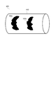
図1に示す配管内の施工システム1は、配管2内を移動しながら配管2の内表面への施工を行う施工ロボット10と制御システム3により構成される。施工ロボット10は、配管2内の施工対象となる領域にわたって配管2内を長手方向に移動しながら配管2内の空間形状と内表面の状態を調査し、当該調査の結果に従って配管2の内表面にレーザ照射することにより施工を行う。制御システム3は、施工ロボット10と通信ケーブルを介して制御信号を送受信しながら施工ロボット10の動作を制御するコンピュータ・システムであってもよい。
The
ここで、配管2内において施工ロボット10を使用した施工作業の対象となる領域は、施工対象範囲R1と呼ばれ、配管2内の長手方向に沿って定義される。この施工対象範囲R1は、配管内の施工システム1を使用した施工作業に先立って、以下において後述する方法により予め設定される。また、施工対象範囲R1は、配管2内の長手方向に沿って配管2内の全範囲(配管2の一方の端部から他方の端部まで)またはその一部のみをカバーするように設定されてもよい。
Here, the area of the
例えば、一例においては、施工対象範囲R1は、以下のように定義されてもよい。配管2の一部がステンレス鋼を含む素材で出来ている場合、配管2の当該部分における内表面は高いエロージョン耐性を有するため、当該部分では施工ロボット10を使用した施工作業を頻繁に行う必要はない。そのため、この場合には、配管2のうち、ステンレス鋼を含まない素材で出来ている部分を施工対象範囲R1として設定すればよい。また、別の一例として、配管2の配管形状が(T字型配管などのように)一筆書きが不可能なトポロジであり、配管2の全体にわたって内表面へのレーザ照射を行う場合、施工対象範囲R1は以下のように設定されてもよい。つまり、この場合には、配管2内で施工ロボット10を複数の異なる移動経路に沿って複数回移動させる必要があるので、配管2の配管形状全体を構成する複数の異なる移動経路の各々を複数の施工対象範囲R1として設定すればよい。
For example, in one example, the construction target range R1 may be defined as follows. When a part of the
以下、図2を参照しながら施工ロボット10の構成について詳しく説明すると共に、図3を参照しながら制御システム3の構成についても詳しく説明する。
Hereinafter, the configuration of the
図2は、幾つかの実施形態に係る配管内の施工システム1のうち施工ロボット10の構成を示す。施工ロボット10は、配管2の長手方向にあらかじめ設定された施工対象範囲R1にわたり、配管2の内表面の状態を検出するための表面状態センサ14と、配管の内表面に向けてレーザ光を照射するレーザ照射部15とを備える。また、施工ロボット10は、表面状態センサ14とレーザ照射部15を配管2内で移動させるための移動手段として第1移動ロボット11aと第2移動ロボット11bを備えている。具体的には、第1移動ロボット11aは、配管2のうち長手方向(d1,d2)における施工対象範囲R1において、表面状態センサ14を配管2の内部において長手方向(d1,d2)に移動させるように構成されている。また、第2移動ロボット11bは、施工対象範囲R1において、レーザ照射部15を配管2の内部において長手方向(d1,d2)に移動させるように構成されている。
FIG. 2 shows the configuration of the
図2に示す施工ロボット10においては、第1移動ロボット11aと第2移動ロボット11bは、単一の移動ロボット11を形成している。また、移動ロボット11には、外部電源から施工ロボット10に駆動電力およびレーザ光発生用の電力を供給するための電源ケーブルC1と、図2を参照しながら後述する制御システム3との間で施工ロボット10を制御するための制御信号を送受信するための通信ケーブルC2が接続されている。なお、第1移動ロボット11aと第2移動ロボット11bは、それぞれ別個の移動ロボットとして実現することも可能である。しかしながら、図1〜図13を参照しながら後述する以下の実施形態では、説明の便宜上、第1移動ロボット11aと第2移動ロボット11bは、単一の移動ロボット11を形成しているものとして説明を行う。
In the
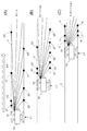
次に、施工ロボット10との間で制御信号を送受信しながら施工ロボット10を制御する制御システム3について図3を参照しながら説明する。図3(A)に示すように、制御システム3は、制御端末31、3次元CADシステム32、演算処理サーバ33およびハブ35を、通信ネットワーク34を介して接続することにより構成されていてもよい。ハブ35には、図2に示す移動ロボット11からの通信ケーブルC2が接続され、制御端末31、3次元CADシステム32および演算処理サーバ33と施工ロボット10との間における信号の送受信を中継している。
Next, a
また、図3(B)に示すように、制御端末31は、制御部310a、自己位置取得部310bおよびマーカー検出部310cを備えている。一実施形態では、制御部310a、自己位置取得部310bおよびマーカー検出部310cは、制御端末31上で実行されるソフトウェア・プログラムとして実装されてもよい。制御部310aは、以下において詳しく後述するように、施工ロボット10を構成する各構成機器に制御指令を送ることで施工ロボット10を構成する各構成機器の動作を制御するように構成されている。自己位置取得部310bは、配管2内を第2移動ロボット11bとして移動中の移動ロボット11の配管2内における自己位置を検出し、制御部310aに出力するように構成されている。マーカー検出部310cについては後述する。また、制御部310aは、以下において後述するマップ取得部311と指令生成部312を含んで構成されていてもよい。
Further, as shown in FIG. 3B, the
マップ取得部311は、配管2の施工対象領域R1内においてレーザ照射を行うべき位置を制御部310aが判断するために使用される地図情報として、図4に示す3次元マップ420を取得する。具体的には、マップ取得部311は、施工対象範囲R1における配管2の内表面の位置座標を示す3次元データ410上においてレーザ光16の照射エリア160が特定された3次元マップ420を取得するように構成されている。なお、図9〜図13を参照しながら詳しく後述するように、マップ取得部311は、以下のようにして3次元マップ420を取得するようにしてもよい。すなわち、表面状態センサ14の走査が完了した施工対象範囲R1についての表面状態センサ14の検出結果に基づいて、施工対象範囲R1における配管2の内表面の3次元位置座標を示す3次元データ410(図4)が以下において後述する手順で算出される。続いて、マップ取得部311は、3次元データ410(図4)上においてレーザ光16の照射エリア160(図4の160aおよび160bなど)が特定された3次元マップ420を取得する。
The
例示的な一実施形態では、マップ取得部311は、表面状態センサ14の走査が完了した施工対象範囲R1についての表面状態センサ14の検出結果に基づいて、以下のようにして3次元マップ420を取得するように構成されていてもよい。まず、マップ取得部311は、施工対象範囲R1における配管2の内表面の空間形状を表す3次元データ410を算出する。続いて、マップ取得部311は、レーザ光16が照射される複数の照射エリア160(図4の160aおよび160bなど)の位置と範囲をそれぞれ表す複数のデータを3次元データ410上に順次重畳してゆくことにより3次元マップを取得する。言い換えるならば、マップ取得部311は、施工対象範囲R1内における配管2の内表面の3次元データ410の上に、照射エリア160の3次元データを重ねる処理を行う。その結果、配管2の内表面の3次元データ410の上に、照射エリア160の3次元データを重ね合せてできた3次元データにより、照射エリア160のジオメトリカルな範囲が3次元マップ420上に表出される。
In one exemplary embodiment, the
この実施形態では、初期段階において、施工対象範囲R1における配管2の内表面の空間形状を表す3次元データ410を算出する。さらにこの実施形態では、初期段階に続く第2段階以降において、レーザ光16を照射すべき複数の照射エリア160(図4の160aおよび160bなど)の位置と範囲をそれぞれ表す複数のデータを3次元データ410上に順次重ね合わせるようにして3次元マップ420を段階的に生成してゆく。その結果、この実施形態によれば、3次元データ410に対して複数の照射エリア160の各々に関するジオメトリック情報をインクリメンタルな方法でそれぞれ追加してゆくことで、3次元マップ420を効率的に合成することができる。
In this embodiment, in the initial stage, three-
また、指令生成部312は、マップ取得部311から受け取った3次元マップ420に基づいて、施工対象範囲R1内における照射エリア160に対して選択的にレーザ光16が照射されるよう、レーザ照射部15および(第2移動ロボット11bとしての)移動ロボット11に指令を送るように構成されている。
Further, the
なお、幾つかの実施形態では、配管2の施工対象範囲R1内において、配管2の内表面が以下のような状態となっている場合に、配管2の内表面の位置座標を示す3次元データ410上においてレーザ光16を照射すべき照射エリア160として特定される。例えば、配管2の施工対象範囲R1内において、配管2の内表面に酸化物スケール(内表面の錆び等)の層が形成されている場合、酸化物スケールの付着面積や酸化物スケールの厚さが大きい場所は、レーザ照射による施工を行う必要性が高い。従って、配管2の内表面のそのような場所は、照射エリア160として特定されてもよい。また、配管2の内表面に形成された塗膜を除去するために配管内の施工システム1を使用するような場合、配管2の施工対象範囲R1内において、塗膜の浮き上がりや塗膜の厚み等が大きい場所は、レーザ照射による施工を行う必要性が高い。従って、配管2の内表面のそのような場所は、照射エリア160として特定されてもよい。
In some embodiments, three-dimensional data indicating the position coordinates of the inner surface of the
一方、制御システム3内の3次元CADシステム32は、配管2の形状設計時に得られた配管2の設計形状のCADデータを配管形状設計情報として自身のデータベース32a内に格納している。3次元CADシステム32は、制御端末31内の自己位置取得部310bからのアクセス要求に応じて配管形状設計情報を自己位置取得部310bに送信する。以下において詳しく後述するように、配管形状情報を受信した自己位置取得部310bは、配管2内を第2移動ロボット11bとして移動中の移動ロボット11の配管2内における自己位置を算出するための演算処理を行う際に、配管形状設計情報を補助情報として使用する。
On the other hand, the three-
また、例示的な一実施形態では、マップ取得部311によって取得される3次元データ410および3次元マップ420を算出する処理は、図3(A)に示す演算処理サーバ33によって以下の手順で実行されてもよい。まず、演算処理サーバ33は、施工ロボット10上に設けられた表面状態センサ14およびその他のセンサ機器を含むセンサ機器類からの計測データを、通信ケーブルC2を介して受け取る。続いて、当該計測データに対して解析処理や演算処理を施すことで制御部310aが施工ロボット10を構成する各構成機器を制御するために使用する制御用入力情報を生成し、制御部310aに出力する。また、施工ロボット10上に設けられたセンサ機器類からの計測データに対して解析処理や演算処理を施すことで自己位置取得部310bが(第2移動ロボット11bとしての)移動ロボット11の自己位置を算出するために使用する入力情報を生成し、自己位置取得部310bに出力する。
Further, in one exemplary embodiment, the process of calculating the three-
次に、例示的な一実施形態に従い、配管2を施工ロボット10が施工する手順および制御システム3によって施工ロボット10を制御する際の制御動作について説明する。まず、施工ロボット10の施工動作と制御システム3による制御動作について説明するのに先立つ準備として、この実施形態で用いられる施工ロボット10の詳細な構成について説明する。
Next, a procedure for constructing the
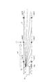
図2に示すように、配管2内を移動する移動ロボット11は、配管2の長手方向(d1,d2)に沿って伸びる筒形状の本体部17を有し、配管2の異なる径方向に沿って本体部17から腕部12および12’がそれぞれ延伸している。また、腕部12および12’の先端部にそれぞれ設けられたクローラ型走行体13および13’は配管2の内表面上を走行可能となるように配管2の内表面上に当接している。そして、駆動モータ18および18’でクローラ型走行体13および13’を駆動することにより移動ロボット11を配管2の長手方向(d1,d2)に沿って移動させることができる。
As shown in FIG. 2, the
また、本体部17の一方の端面17aには、外部電源から施工ロボット10に電力を供給するための電源ケーブルC1および制御システム3との間で施工ロボット10を制御するための制御信号を送受信するための通信ケーブルC2が接続されている。また、本体部17の他方の端面17bには、レーザ照射部15のうち、以下において後述するノズル部15cおよびリングモータ部15dが配設されている。また、本体部17の側面部を構成する上側壁面上には、以下において後述する表面状態センサ14が設けられ、表面状態センサ14は、本体部17の上側壁面上の端面17bに近接した場所に位置している。
Further, a control signal for controlling the
一例においては、図5に示すように本体部17から配管2の周方向にそって120°の間隔を空けて3本の腕部12a、12bおよび12cが配管2の径方向に沿って伸び、3本の腕部12a、12bおよび12cの先端部にそれぞれ設けられたクローラ型走行体13a、13bおよび13cは配管2の内表面上を走行可能となるように配管2の内表面上に当接するように構成されていてもよい。腕部12a、12bおよび12cは、本体部17とクローラ型走行体13a、13bおよび13cとの間の距離を調節可能となるように伸縮自在に構成されていてもよい。その結果、配管2の内径に合わせてクローラ型走行体13a、13bおよび13cが適切な押圧力で配管2の内表面に当接するように本体部17とクローラ型走行体13a、13bおよび13cとの間の距離が調整される。
In one example, as shown in FIG. 5, three
図5に示す移動ロボット11の構成において、クローラ型走行体13(13a〜13c)を本体部17から延びる腕部12(12a〜12c)によって支持する構造を移動ロボット11の進行方向前方から見た正面図としてさらに詳しく示したのが図6である。上述したように、移動ロボット11は、配管2の長手方向に沿って延在する長尺形状に形成された本体部17を有し、図6においては、本体部17は断面が円形で配管2の長手方向に延在する円筒形場を有するものとして描かれている。また、図6に示すように、本体部17の周方向の異なる位置に複数配置され、配管2の内表面上を走行可能に構成された複数のクローラ型走行体13(13a〜13c)と、本体部17の周方向の異なる位置に複数配置され、本体部17に対してクローラ型走行体13(13a〜13c)を配管2の径方向に沿って拡縮可能に支持するように構成された伸縮機構をそれぞれ有する複数の腕部12(12a〜12c)と、を含んで構成される。
In the configuration of the
図6に示す上記構成によれば、移動ロボット11の本体部17の周方向に沿った複数の位置にそれぞれ設置された複数のクローラ型走行体13(13a〜13c)を複数の腕部12(12a〜12c)がそれぞれ備える伸縮機構によって径方向に沿って拡縮することができることで、以下の技術的利点を得られる。
According to the above configuration shown in FIG. 6, a plurality of crawler-type traveling bodies 13 (13a to 13c) installed at a plurality of positions along the circumferential direction of the
例えば、移動ロボット11が配管2の内表面と接触したり、配管2の屈曲部において擱座したりして配管2内で立ち往生し、移動ロボット11が操作不能となった場合を考える。この場合、複数のクローラ型走行体13(13a〜13c)をそれぞれ支持する複数の腕部12(12a〜12c)を収縮させることができる。従って、移動ロボット11を配管2内から回収する際に、本体部17から突き出した腕部12(12a〜12c)とクローラ型走行体13(13a〜13c)が邪魔にならないようにすることができる。以上より、上記構成によれば、移動ロボット11が配管2内で立ち往生したことにより配管2内で移動ロボット11を操作不能となった場合でも、移動ロボット11の回収を円滑に行うことができる。
For example, consider a case where the
また、図6に示す実施形態では、複数の腕部12(12a〜12c)がそれぞれ有する伸縮機構は、以下において後述するバネ部材121(121a〜121c)とシリンダ装置122(122a〜122c)と伸縮量調整部123(123a〜123c)により構成されていてもよい。ここで、バネ部材121(121a〜121c)は、配管2の径方向に沿って付勢されたバネによりクローラ型走行体13(13a〜13c)を配管2の内表面に押し付けるように伸縮する部材である。また、シリンダ装置122(122a〜122c)は、配管2の径方向に沿った伸縮動作により、本体部17に対する腕部12(12a〜12c)の伸縮量を変化させるように構成された部材である。一例においては、シリンダ装置122(122a〜122c)は、エアシリンダを用いて実現されてもよい。また、伸縮量調整部123(123a〜123c)は、制御部310aから受信した伸縮指示信号に応じてシリンダ装置122(122a〜122c)を駆動することにより、腕部12(12a〜12c)の伸縮量を制御するように構成されている。
Further, in the embodiment shown in FIG. 6, the expansion / contraction mechanism of each of the plurality of arm portions 12 (12a to 12c) is expanded / contracted with the spring member 121 (121a to 121c) and the cylinder device 122 (122a to 122c) described later. It may be composed of the quantity adjusting unit 123 (123a to 123c). Here, the spring member 121 (121a to 121c) is a member that expands and contracts so as to press the crawler type traveling body 13 (13a to 13c) against the inner surface of the
従って、この実施形態によれば、配管2内で移動ロボット11が擱座したことを移動ロボット11に搭載されたセンサ等によりユーザが検知した場合、以下のようにして擱座した移動ロボット11を配管2内から取り出す作業を円滑化することができる。まず、ユーザは、腕部12(12a〜12c)を径方向の内側に向けて収縮させるためのコマンドを制御部310aに与える。例えば、ユーザは、制御端末31のキーボード等を操作することで、そのようなコマンドを制御部310aに与えるようにしてもよい。すると、当該コマンドを受け取った制御部310aは、当該コマンドに応じて伸縮量調整部123(123a〜123c)に伸縮指示信号を送信する。その際、制御部310aから送信される伸縮指示信号は、腕部12(12a〜12c)を径方向の内側に最大限収縮させるための伸縮量を伸縮量調整部123(123a〜123c)に指示する制御信号であってもよい。このようにして、制御端末31上の制御部310aを介した遠隔操作により、複数の腕部12(12a〜12c)の伸縮量が遠隔制御される。そのような遠隔制御の結果、複数のクローラ型走行体13(13a〜13c)をそれぞれ支持する複数の腕部12(12a〜12c)を本体部17側に収縮させることができる。従って、移動ロボット11を配管2内から回収する際に、上記のような遠隔操作を行うことで、本体部17から突き出した腕部12(12a〜12c)とクローラ型走行体13(13a〜13c)が邪魔にならないようにすることができる。
Therefore, according to this embodiment, when the user detects that the
さらに図6に示す実施形態では、制御部310aは、伸縮量調整部123(123a〜123c)に対して与える伸縮指示信号を配管2の内表面の形状に応じて適応的に選択するように構成されていてもよい。その結果、制御部310aは、伸縮量調整部123(123a〜123c)に対して与える伸縮指示信号を適応的に選択することにより、配管2の内表面に対してクローラ型走行体13(13a〜13c)の走行に必要な接地力を確保するようにシリンダ装置122(122a〜122c)を制御することができる。
Further, in the embodiment shown in FIG. 6, the
このように、複数の腕部12(12a〜12c)がそれぞれ有する伸縮機構が図6を参照しながら上述したような構造を有し、制御部310aが伸縮量調整部123(123a〜123c)に対して与える伸縮指示信号を配管2の内表面の形状に応じて適応的に選択することにより、以下のような技術的利点が得られる。例えば、配管2の形状が直角に曲がった屈曲部を有するT字型である場合、当該屈曲部は、配管2内の直管部とは異なる特異な内壁面形状を有する。そのため、移動ロボット11が当該屈曲部を円滑に通り抜けるためには、当該内壁面形状に合わせて腕部12(12a〜12c)の伸縮動作を適切に行うことが必要となる。そこで、上記構成では、複数の腕部12(12a〜12c)の伸縮機構をそれぞれ構成するバネ部材121(121a〜121c)とシリンダ装置122(122a〜122c)の働きにより、配管2の内表面に対し、クローラ型走行体13(13a〜13c)の走行に必要な接地力を確保するようにしている。具体的には、移動ロボット11が配管内の屈曲部を通過する際、バネ部材121(121a〜121c)とシリンダ装置122(122a〜122c)の働きにより、以下のようにして必要な接地力が確保される。すなわち、屈曲部における特異な内壁面形状に合わせてクローラ型走行体13(13a〜13c)を配管2の内表面に押し付けることで、配管2の内表面に対してクローラ型走行体13(13a〜13c)の走行に必要な接地力を維持し続けることが可能となる。
As described above, the expansion / contraction mechanism of each of the plurality of arm portions 12 (12a to 12c) has the structure as described above with reference to FIG. 6, and the
なお、配管内の施工システム1が配管2に対して行う施工作業が配管2の内表面に形成された酸化物スケールの除去作業である場合、レーザ照射部15からのレーザ光の照射によって当該酸化物スケールの層が焼灼されると、粉塵状の燃えカスが生成される。従って、その場合には、ノズル部15cに吸引ホースを介して接続された真空ポンプ(図示なし)を移動ロボット11の本体部17内にさらに設け、ノズル15cの先端のレーザ射出口15bから粉塵状の燃えカスを吸引して回収することが可能である。
When the construction work performed on the
続いて、施工ロボット10の構成に関する以上の説明を踏まえ、施工ロボット10の施工動作と制御システム3による制御動作について説明する。配管2の中に投入された施工ロボット10は、配管2内を施工するために、まず最初に第1作業フェーズを実行する。第1作業フェーズにおいては、(第1移動ロボット11aとしての)移動ロボット11は、配管2内の施工対象範囲R1全体に跨る移動経路上を移動する。それにより、(第1移動ロボット11aとしての)移動ロボット11に搭載された表面状態センサ14は、配管2内を移動しながら、配管2内の施工対象範囲R1全体を走査する。
Subsequently, based on the above description regarding the configuration of the
このようにして配管2内の施工対象範囲R1において表面状態センサ14による走査を行い、施工対象範囲R1全体にわたって走査が完了すると、表面状態センサ14は、当該走査が完了した施工対象範囲R1全体にわたる走査結果を表す空間計測情報をセンサ出力データとして出力する。例示的な一実施形態では、施工対象範囲R1全体にわたって走査を行い、施工対象範囲R1全体にわたる走査結果を表す空間計測情報を出力する表面状態センサ14は、図7に示すような空間認識センサ14として構成されていてもよい。図7に示すように、表面状態センサ14は、少なくとも一台の3次元スキャナ140を含んで構成されてもよい。この3次元スキャナ140は、走査信号波を全方位にわたって走査する形で照射するための照射口140aと照射された走査信号波の反射波を検出する反射波検出センサ140bを備えている。この実施形態では、3次元スキャナ140は、施工対象範囲R1における配管2内の表面状態を計測する第1の3次元スキャナ141として動作する。なお、一例においては、3次元スキャナ140の照射口140aから照射される走査信号波は、測距用レーザ、電磁波および超音波を含む任意の信号波であってもよい。
In this way, when the
第1の3次元スキャナ141は、(第1移動ロボット11aとしての)移動ロボット11によって施工対象範囲R1にて配管2内を移動可能に構成されている。そして、第1の3次元スキャナ141は、走査信号波を照射して配管2内の3次元空間を走査することで、走査信号波の照射源(例えば、図7に示す照射口140a)から配管2内の空間を構成する複数の点までのそれぞれの距離と方向を表す第1点群データを配管2内の空間形状を表す空間計測情報として取得する。このとき、配管2の施工対象範囲R1内を配管2の軸方向に沿って移動中に、第1の3次元スキャナ141は、走査信号波の走査によって配管2の軸方向に沿った各位置において施工ロボット10の近傍空間の点群データを取得する。そして、配管2の軸方向(長手方向)に沿った各位置の近傍空間について取得された点群データを配管2の軸方向(長手方向)に沿って合成することで施工対象範囲R1全体についての第1点群データを得ることができる。
The first three-dimensional scanner 141 is configured to be movable in the
例示的な一実施形態では、第1の3次元スキャナ141は、測距用レーザを照射して配管2内の3次元空間を走査することで、測距用レーザの照射源(例えば、図7に示す照射口140a)から配管2内の空間を構成する複数の点までのそれぞれの距離と方向を表す第1点群データ取得するSLAM装置として実現されてもよい。この実施形態では、SLAM装置として実装された第1の3次元スキャナ141は、図8を参照しながら以下において後述する方法により、配管2の内部空間全体を表す点群データを第1点群データとして取得するように構成されていてもよい。
In one exemplary embodiment, the first three-dimensional scanner 141 irradiates the distance-finding laser and scans the three-dimensional space in the
図8を参照すると、移動ロボット11は、矢印w1で示される進行方向に移動中の状態であり、時刻T1=tにおいて配管2内の長手方向位置L1に位置している(図8A)。このとき、移動ロボット11は、長手方向位置L1において走査信号波による空間走査を行うことで点群P(図8Aに示すp1〜p8など)に関する点群データを取得する。続く時刻T2=t+Δtにおいては、移動ロボット11は、配管2内の長手方向位置L2に移動しており(図8B)、長手方向位置L2において走査信号波による空間走査を行うことで点群Q(図8Bに示すq1〜q8など)に関する点群データを取得する。続く時刻T3=t+2×Δtにおいては、移動ロボット11は、配管2内の長手方向位置L3に移動しており(図8C)、長手方向位置L3において走査信号波による空間走査を行うことで点群R(図8Cに示すr1〜r6など)に関する点群データを取得する。
Referring to FIG. 8, the
そして、点群P、QおよびRに関する点群データを矢印w1に沿って合成することで、長手方向位置L1〜L3までの範囲にわたって配管2の内部空間を表す点群データを取得することができる。このように、配管2内の長手方向に沿って並ぶ複数の位置の各々において移動ロボット11がローカルな点群データを取得し、複数の位置においてそれぞれ取得したローカルな点群データを配管2の長手方向に沿って合成することで配管2の内部空間全体を表す点群データを第1点群データとして取得することが可能となる。
Then, by synthesizing the point cloud data relating to the point clouds P, Q and R along the arrow w1, it is possible to acquire the point cloud data representing the internal space of the
なお、以下において後述するように、第1の3次元スキャナ141を用いて配管2の内部空間形状を表す第1点群データとして上記のように取得される空間計測情報は、図4に示す3次元マップ420を生成するために用いられてもよい。また、表面状態センサ14は、配管2の内表面を撮影した画像を制御部31に出力する撮像装置142をさらに含んで構成されてもよく、撮像装置142は、レンズ部142aを備える。一実施形態では、撮像装置142によって撮影された画像は、施工対象範囲R1における配管2の内表面の表面状態を画像認識処理により詳細に把握することによって、施工対象範囲R1における照射エリア160を検出するために用いられてもよい。また、別の一実施形態では、撮像装置142によって撮影された画像は、施工対象範囲R1における配管2の内表面の表面状態を画像認識処理により詳細に把握することによって、施工対象範囲R1における配管2の内表面に対してレーザ光を照射する際の照射条件を制御するために用いられてもよい。
As will be described later, the spatial measurement information acquired as described above as the first point cloud data representing the internal space shape of the
この実施形態では、表面状態センサ14による走査が完了した施工対象範囲R1全体にわたる走査結果を表す空間計測情報は、表面状態センサ14が備える第1の3次元スキャナ141が配管2内の空間形状を3次元的に計測して得られる計測データとして得られてもよい。例えば、この空間計測情報は、第1の3次元スキャナ141により走査信号波を照射して配管2内の3次元空間を走査することで、走査信号波の照射源(例えば、図7に示す照射口140a)から配管2内の空間を構成する複数の点までのそれぞれの距離と方向を表す第1点群データとして得られてもよい。
In this embodiment, the spatial measurement information representing the scanning result over the entire construction target range R1 that has been scanned by the
以上のようにして、表面状態センサ14内の第1の3次元スキャナ141により第1点群データとして計測された空間計測情報は、通信ケーブルC2およびハブ35を経由して演算処理サーバ33へと送信される。第1点群データを受け取った演算処理サーバは、第1点群データに対して幾何学的な演算処理を施すことで、施工対象範囲R1における配管2の内表面の3次元位置座標を示す3次元データ410を算出してもよい。さらに、演算処理サーバ33は、第1点群データに対してさらなる空間形状解析処理を施すことで、3次元データ410上においてレーザ光16の照射エリア160が特定された3次元マップ420を算出してもよい。以上のようにして、3次元データ410および3次元マップ420が算出されると、演算処理サーバ33は、3次元データ410および3次元マップ420を制御部310a内のマップ取得部311に送信する。以上のようにして、マップ取得部311は、施工対象範囲R1における配管2の内表面の3次元位置座標を示す3次元データ410上においてレーザ光16の照射エリア160が特定された3次元マップ420を取得することとなる。
As described above, the spatial measurement information measured as the first point cloud data by the first three-dimensional scanner 141 in the
なお、この実施形態では、上記のようにして3次元データ410および3次元マップ420を算出する処理は、演算処理サーバ33によって実行されるものとして説明した。しかしながら、上記のようにして3次元データ410および3次元マップ420を算出する処理は、制御部310aにおいて実行するようにしてもよい。
In this embodiment, the process of calculating the three-
施工ロボット10が配管2内を移動することにより第1作業フェーズを完了し、マップ取得部311が、配管2内の施工対象範囲R1について3次元データ410および3次元マップ420を取得すると、続いて、後述する第2作業フェーズが行われる。第2作業フェーズにおいては、施工ロボット10は、配管2内の施工対象範囲R1全体に跨る移動経路を移動しながら施工対象範囲R1における配管2の内表面に対してレーザ照射部15によるレーザ照射を行う。
When the
第2作業フェーズの実行中において、制御部310aは、(第2移動ロボット11bとしての)移動ロボット11により配管2内を移動可能に構成されたレーザ照射部15を制御する。同時に、制御部310aは、第2移動ロボット11bとして移動中の移動ロボット11の自己位置を検出しながら(第2移動ロボット11bとしての)移動ロボット11の移動速度や移動方向を制御する。これにより、制御部310aは、施工ロボット10が第2作業フェーズにおいて配管2内を移動中に、配管2の内表面に対してレーザ光を照射する照射位置やレーザ光の照射条件を適切に制御する。より具体的には、制御部310a内の指令生成部312は、以下の制御動作を実行する。
During the execution of the second work phase, the
まず、指令生成部312は、制御部310a内のマップ取得部311から配管2の施工対象範囲R1についての3次元データ410および3次元マップ420を受け取る。続いて、指令生成部312は、3次元マップ420に基づいて、施工対象範囲R1内における照射エリア160に対して選択的にレーザ光16が照射されるよう、レーザ照射部15および(第2移動ロボット11bとしての)移動ロボット11に制御指令を送る。その際、制御部310a内の指令生成部312は、表面状態センサ14が検出した配管2内の表面状態に基づいてレーザ光の照射条件を制御するようにしてもよい。それにより、配管2の内表面にレーザ照射を行うことによる施工作業の種別(酸化物スケールの除去、洗浄、塗膜除去など)、配管の内表面の表面状態(例えば、酸化物スケールの付着面積、酸化物スケールの厚さ、塗膜の浮き上がり、塗膜の厚み等)に応じてレーザ光16の照射条件を制御しながら施工対象範囲R1にわたってレーザ照射による施工作業を行うことができる。その結果、配管2内の各施工箇所において、レーザ照射を必要な出力で必要な時間だけ行うことで、配管2の肉厚をレーザ照射により必要以上に削り取ってしまうことを防止することができる。
First, the
次に、この実施形態で用いられるレーザ照射部15の具体的構成について説明する。レーザ照射部15を構成するノズル部15cは、レーザ光16の照射方向が回転するように配管2内の周方向に沿って回動自在に構成されている。図2に示すように、ノズル部15cは、レーザ光発生装置15eからのレーザ光16を反射ミラー15aによりレーザ射出口15bへと導くように構成されている。なお、レーザ照射部15を構成するレーザ光発生装置15eは、電源ケーブルC1から供給される電力をレーザ発生用のエネルギーとして用い、ノズル部15cの反射ミラー15aへと導かれるレーザ光16を発生させる装置であり、本体部17に内蔵されていてもよい。ここで、ノズル部15cの内部において方向y1または方向y2へと反射ミラー15aの一端を動かすことで、レーザ光16がレーザ射出口15bから射出される方向を配管2の長手方向(d1,d2)に沿って微調整することができる。また、レーザ照射部15を構成するリングモータ部15dは、配管2内の周方向に沿ってノズル部15cが回動自在となるようにノズル部15cの基部を本体部17の端部17bに接続するリングモータである。つまり、レーザ光16の照射方向が配管2内の周方向に沿って角速度ωで回転するようにリングモータ部15dの回転速度を制御すると、リングモータ部15dの回転に伴ってノズル部15cも配管2内の周方向に沿って回転する。上記のようなリングモータ部15dによってノズル部15cが周方向に沿って回転自在となるようにすることで、レーザ光発生装置15eを含むレーザ光源全体が本体部17内で周方向に回転しない構成とすることができる。このようにレーザ光源全体が回転せずに本体部17内で周方向に固定された構成とすることによって、機器類のケーブル等の絡まりを防止することができる。
Next, a specific configuration of the
以下、第2作業フェーズにおいて、配管2内で施工ロボット10が行う動作と施工ロボット10の動作を制御するために制御部310aが実行する制御動作についてさらに詳しく説明する。第2作業フェーズにおいては、(第2移動ロボット11bとしての)移動ロボット11は、配管2内の施工対象範囲R1全体に跨る移動経路上を移動する。その際、制御部310aの指令生成部312は、制御部310aのマップ取得部311から受け取った3次元マップ420を参照し、配管2の施工対象範囲R1内のどの位置に照射エリア160が存在し、照射エリア160がどのような範囲に広がっているかを把握する。
Hereinafter, in the second work phase, the operation performed by the
続いて、指令生成部312は、レーザ光16の照射方向を配管2内の周方向に沿って回転させる際の回転角速度ωを、照射エリア160の周方向に沿った広がり幅(周方向の長さ)に応じて制御する必要がある。何故なら、配管2の周方向においてレーザ照射を行うべき照射エリア160が占める角度範囲が広い軸方向位置(配管2の長手方向における位置)では、移動ロボット11(第2移動ロボット11b)上のレーザ照射部15は、配管2内の周方向に沿ったレーザ照射の掃引を広範囲にわたって重点的に行う必要があるからである。逆に、照射エリア160が占める角度範囲が狭い軸方向位置では、移動ロボット11(第2移動ロボット11b)上のレーザ照射部15は、レーザ照射の掃引を短時間で済ませればよい。そのために、指令生成部312は、照射エリア160が配管2の周方向に占める角度範囲の広さに合わせて、レーザ光16の照射方向が適切な回転角速度ωで回転するように、配管2内の周方向に沿ったノズル部15cの回転速度を制御する。
Subsequently, the
また、指令生成部312は、配管2内の長手方向に沿った各位置(軸方向位置)において、配管2の周方向においてレーザ照射を行うべき照射エリア160が占める角度範囲に応じて配管2の長手方向に沿った移動ロボット11(第2移動ロボット11b)の走行速度を制御するようにしている。何故なら、照射エリア160が占める角度範囲が広く、配管2内の周方向に沿ったレーザ照射の掃引を広範囲にわたって重点的に行う必要がある場所では移動ロボット11(第2移動ロボット11b)の走行速度を緩める必要があるからである。
Further, the
以上のような制御機能を実現するために、指令生成部312は、配管2内の空間構造を表す3次元マップ420の上に、移動ロボット11(第2移動ロボット11b)によって移動するレーザ照射部15の現在の自己位置を投影する処理動作を行う。その上で、指令生成部312は、レーザ照射部15の現在の自己位置に応じて、3次元マップ420によって特定される施工対象範囲10内の照射エリア160に対して選択的にレーザ光16が照射されるよう、レーザ照射部15および移動ロボット11(第2移動ロボット11b)に制御指令を送る。これにより、制御部310aは、(第2移動ロボット11bとしての)移動ロボット11によって移動させられているレーザ照射部15の自己位置が3次元マップ420上で特定される照射エリア160に含まれる場合にレーザ光16の照射を行うようにレーザ照射部15を制御することが可能となる。
In order to realize the above control function, the
以上のように、指令生成部312が行う制御動作への入力情報として移動ロボット11(第2移動ロボット11)によって移動するレーザ照射部15の自己位置を検出する必要がある。そこで、制御端末31内で動作する自己位置取得部310bは、図9および図10を参照しながら後述する手法に従って移動ロボット11(第2移動ロボット11b)によって移動するレーザ照射部15が現在位置している配管2内の自己位置を表す自己位置情報を算出する。続いて、自己位置取得部310bから自己位置情報を受け取った指令生成部312は、移動ロボット11(第2移動ロボット11b)によって移動するレーザ照射部15の自己位置が照射エリア160内に含まれるか否かを判定する。そして、指令生成部312は、当該自己位置が照射エリア160内に含まれると判定された場合にレーザ光16の照射を行うようにレーザ照射部15に制御指令を送信する。
As described above, it is necessary to detect the self-position of the
図9は、施工ロボット10が備える第2の3次元スキャナ143のみを用いて計測されたデータから自己位置情報を算出する例について示している。まず、図9に示す自己位置情報の具体的な算出方法を説明するのに先立って、自己位置の検出に用いられる第2の3次元スキャナ143について詳しく説明する。上述した表面状態センサ14が備える3次元スキャナ140は、3次元マップ420を得るための第1の3次元スキャナ141として動作するだけでなく、以下のような第2の3次元スキャナ143としても動作するように構成されてもよい。すなわち、第2の3次元スキャナ143は、(第2移動ロボット11bとしての)移動ロボット11によって施工対象範囲R1にて配管2内を移動可能に構成されている3次元スキャナ140により実現される。その上で、第2の3次元スキャナ143は、自己位置取得部310bが配管2内を移動中の施工ロボット10の自己位置を算出するために用いられる。また、第2の3次元スキャナ143は、第1の3次元スキャナ141と同様に、走査信号波を照射して配管2内の3次元空間を走査することで、配管2内の空間を構成する複数の点までのそれぞれの距離を表す第2点群データを配管2内の空間形状を表す空間計測情報として取得するように構成されている。
FIG. 9 shows an example of calculating self-position information from data measured using only the second three-dimensional scanner 143 included in the
以上のように、施工ロボット10では、第1の3次元スキャナ141と第2の3次元スキャナ143は同一の3次元スキャナ140によって表面状態センサ14内に実現されている。しかしながら、別の実施形態では、第2の3次元スキャナ143は、3次元スキャナ140を含む表面状態センサ14とは別個の独立した3次元スキャナとして設けるようにしてもよい。
As described above, in the
以上の説明を踏まえ、図9に示す実施形態に従って自己位置情報を算出する具体的な方法について説明する。図9に示すように、第2の3次元スキャナ143は、配管2の施工対象範囲R1内を矢印w1に沿って移動ロボット11(第2移動ロボット11b)により移動中である。そして、移動中の第2の3次元スキャナ143は、走査信号波を照射して配管2内の3次元空間を走査することで、配管2内の空間を構成する複数の点までのそれぞれの距離を表す第2点群データを逐次計測する。施工対象範囲R1内の各位置において第2点群データが計測されるたびに、マップ取得部311から受け取った配管2内の3次元マップ420に対して第2点群データを照合する処理がなされ、この照合処理の結果に基づいて自己位置情報が算出される。
Based on the above description, a specific method for calculating self-position information according to the embodiment shown in FIG. 9 will be described. As shown in FIG. 9, the second three-dimensional scanner 143 is moving along the arrow w1 in the construction target range R1 of the
続いて、移動ロボット11(第2移動ロボット11bとしての)移動ロボット11が図9に示す位置Lに来たときに、移動ロボット11が配管2内でスリップし、移動ロボット11の周方向位置および/または軸方向位置が急にずれたとする。その場合、(第2移動ロボット11bとしての)移動ロボット11が位置Lから先に移動し続けている間に、自己位置取得部310bは、逐次計測された第2点群データと3次元マップ420との間の照合処理により移動ロボット11の周方向および/または軸方向における位置ズレ量を算出する。そして、自己位置取得部310bは、この位置ズレ量を用いて自己位置情報を補正する。なお、当該位置ズレ量を自己位置取得部310bから受信した制御部310aは、当該位置ズレ量をゼロにするように移動ロボット11の走行軌道を修正するために、制御指令を移動ロボット11(第2移動ロボット11b)に送信してもよい。
Subsequently, when the mobile robot 11 (as the second
続いて、自己位置情報を算出するためのさらに別の実施形態として、施工ロボット10が備える第2の3次元スキャナ143を用いて計測されたデータのみならず、配管形状設計情報をさらに利用して自己位置情報を算出する例について説明する。配管形状設計情報は、配管2の設計時に生成された配管2の設計形状を表す3次元CADデータであり、自己位置取得部310bからのアクセス要求に応じて3次元CADシステム32から自己位置取得部310bに出力される。図9に示すように、配管2の施工対象範囲R1内を矢印w1に沿って移動ロボット11(第2移動ロボット11b)により移動中に、第2の3次元スキャナ143により第2点群データが得られるたびに、自己位置取得部310bは、第2点群データを配管形状設計情報と照合することで自己位置情報を算出する。
Subsequently, as yet another embodiment for calculating the self-position information, not only the data measured by the second three-dimensional scanner 143 included in the
以上より、この実施形態によれば、配管形状設計情報に第2点群データを照合することで、施工ロボット10の現在の軸方向位置だけでなく、施工ロボット10の管軸周りの姿勢をも特定することができる。よって、配管2内において施工ロボット10が移動する際に、施工ロボット10の姿勢が変化しても、このことを考慮した自己位置情報を取得することができ、配管形状設計情報を用いない場合と比べてレーザ光16の照射エリア160を高精度に特定することができる。
From the above, according to this embodiment, by collating the second point cloud data with the pipe shape design information, not only the current axial position of the
図10は、施工ロボット10が備える第2の3次元スキャナ143を用いて計測されたデータだけでなく、配管2上に形成されたマーカーの位置を利用して自己位置情報を算出する例について示している。なお、図10に示す実施形態では、配管2の継ぎ目部分に形成された溶接線(図10に示すmk11〜mk32)をマーカー用いるものとしており、この溶接線mk11〜mk32は、配管2の軸方向に沿って並ぶ規則的な位置に複数配置されている。また、図10に示すこの実施形態では、制御端末31は、第2作業フェーズにおいて(第2移動ロボット11bとしての)移動ロボット11が配管2の施工対象範囲R1内を移動中に、配管2に形成されたマーカーの位置を検出するためのマーカー検出部310cをさらに備える。マーカー検出部310cは、移動ロボット11の下部に設けられたマーカー検出器144と接続されている。一実施形態では、このマーカー検出器144は、移動ロボット11の下部に配管2の内表面と近接するように設けられた画像センサ144(図10)であってもよい。そして、移動ロボット11の移動に伴って画像センサ144がマーカーの近傍を通過すると、その時点で画像センサ144から当該マーカーを通過した旨を表す信号が制御端末31に出力される。画像センサ144が出力するこの信号のタイミングに基づいて、制御端末31は、3次元マップ420および第2点群データに対してマーカー位置を表す情報を埋め込むことができる。
FIG. 10 shows an example of calculating self-position information using not only the data measured by the second three-dimensional scanner 143 included in the
図10に示すように、第2作業フェーズの開始後、第2の3次元スキャナ143は、配管2の施工対象範囲R1内を矢印w1に沿って移動ロボット11(第2移動ロボット11b)により移動する。そして、移動中の第2の3次元スキャナ143は、走査信号波を照射して配管2内の3次元空間を走査することで、配管2内の空間を構成する複数の点までのそれぞれの距離を表す第2点群データを逐次計測する。また、マーカー検出器310cに接続された画像センサ144からマーカーを通過した旨を表す信号が得られるたびに、マーカー検出部310cは、自己位置取得部310bから受け取った第2点群データ上にマーカーの検出位置を重ね合わせて自己位置取得部310bに返送する。その上で、マーカー検出器310cは、第2点群データ上に重ね合されたマーカーの検出位置と、3次元マップ420に含まれるマーカー位置情報とを照合することにより自己位置情報を算出する。
As shown in FIG. 10, after the start of the second work phase, the second three-dimensional scanner 143 moves in the construction target range R1 of the
続いて、(第2移動ロボット11bとしての)移動ロボット11が図10に示す位置L1に来たときに、移動ロボット11が配管2内でスリップし、移動ロボット11の周方向位置および/または軸方向位置が急にずれたとする。その場合、(第2移動ロボット11bとしての)移動ロボット11が位置L1から先に移動し続けている間に、自己位置取得部310bは、逐次計測された第2点群データ上に重ね合わされたマーカー検出位置と3次元マップ420に含まれるマーカー位置情報との間の照合処理により移動ロボット11の軸方向における位置ズレ量を算出する。そして、自己位置取得部310bは、この位置ズレ量を用いて自己位置情報を補正する。なお、当該位置ズレ量を自己位置取得部310bから受信した制御部310aは、当該位置ズレ量をゼロにするように移動ロボット11の走行軌道を修正するために、制御指令を移動ロボット11(第2移動ロボット11b)に送信してもよい。
Subsequently, when the mobile robot 11 (as the second
以上より、この実施形態によれば、第2の3次元スキャナ143によって取得した第2点群データ上に重ね合されたマーカーの検出位置と、3次元マップ420に含まれるマーカーの位置情報と、を照合することで、マーカーの位置を基準として3次元マップ420との関係で自己位置を精度良く特定することができる。
From the above, according to this embodiment, the detection position of the marker superimposed on the second point cloud data acquired by the second three-dimensional scanner 143, the position information of the marker included in the three-
続いて、自己位置情報を算出するためのさらに別の実施形態として、施工ロボット10が備える第2の3次元スキャナ143を用いて計測されたデータのみならず、施工ロボット10が備えるジャイロ・センサ19aおよび加速度センサ19bをさらに利用して自己位置情報を算出する例について説明する。施工ロボット10の本体部17の内部には、配管2の周方向に沿った施工ロボット10の姿勢位置や配管2の軸方向に沿った施工ロボット10の移動量を検出するために用いられるセンサとして、ジャイロ・センサおよび加速度センサ19が設けられている(図2)。ジャイロ・センサ19aは、施工ロボット10の姿勢の変化を3次元極座標系で表した変位ベクトルとして自己位置取得部310bに出力する。また、加速度センサ19bは、配管2の軸方向に沿った施工ロボット10の位置変化を3次元デカルト座標系で表した変位ベクトルとして自己位置取得部310bに出力する。従って、ジャイロ・センサ19aおよび加速度センサ19bが逐次的に出力する変位ベクトルを施工ロボット10の移動開始時から累算することにより、施工ロボット10の配管2内での姿勢と配管2の軸方向に沿った位置が算出できる。以上より、自己位置取得部310bは、当該算出された施工ロボット10の姿勢と軸方向位置を第2点群データと照合することで自己位置情報を算出することができる。
Subsequently, as yet another embodiment for calculating the self-position information, not only the data measured by the second three-dimensional scanner 143 included in the
以上より、この実施形態によれば、ジャイロ・センサ19aおよび加速度センサ19bから計測値として得られる少量のデータに対して簡単な演算処理を施すことで、ジャイロ・センサ19aおよび加速度センサ19bを搭載した移動ロボット11(第2移動ロボット11b)の現在の自己位置を特定することができる。その結果、この実施形態によれば、簡単な演算処理を実行するだけで移動ロボット11(第2移動ロボット11b)の自己位置を短時間で精度良く特定することができる。なお、ジャイロ・センサ19aおよび加速度センサ19bの用途は、上記用途に限定されず、表面状態センサ14により配管2内の表面状態を走査しながら第1移動ロボット11aとして配管2内を移動中の移動ロボット11により以下のように利用されてもよい。すなわち、第1移動ロボット11aとして配管2内を走行中の移動ロボット11がジャイロ・センサ19aおよび加速度センサ19bを用いて自身の姿勢認識を行いながら配管2内を走行するようにしてもよい。このようにすることで、移動ロボット11は、自身の配管2内での姿勢を正しい向きに維持したまま走行することが可能となる。同様に、レーザ照射を行いながら第2移動ロボット11bとして配管2内を移動中の移動ロボット11もまた、自身の姿勢認識を行いながら配管2内を走行するためにジャイロ・センサ19aおよび加速度センサ19bを用いることが可能である。
From the above, according to this embodiment, the
続いて、自己位置情報を算出するためのさらに別の実施形態として、施工ロボット10が備える第2の3次元スキャナ143を用いて計測されたデータのみならず、施工ロボット10を駆動するための駆動モータに取り付けられたエンコーダ20の出力値をさらに利用して自己位置情報を算出する例について説明する。施工ロボット10においてクローラ13を駆動するための駆動モータ18および18’には、駆動モータ18および18’の回転量をカウントして得られる計測信号を出力するエンコーダ20および20’が取り付けられている(図2)。エンコーダ20は、施工ロボット10の移動ロボット11を配管2内で走行させるための駆動モータ18および18’の回転量をカウントして得られる計測信号を出力するので、エンコーダ20が出力するカウント値を累算することにより、配管2内の軸方向に沿ってみたときの施工ロボット10の位置が算出できる。以上より、自己位置取得部310bは、当該算出された施工ロボット10の軸方向位置を第2点群データと照合することで自己位置情報を算出することができる。
Subsequently, as yet another embodiment for calculating the self-position information, not only the data measured by the second three-dimensional scanner 143 included in the
また、自己位置情報を算出するためのさらに別の実施形態を図11に示す。図11(A)に示す実施形態では、配管2内には、制御部310aからの鳴動指令crに応じて音波swを発する複数の音源ss(ss1およびss2)が設けられる。一例においては、複数の音源ss(ss1およびss2)は、配管2内の施工対象範囲R1の始端部と終端部に設けるようにしてもよい。また、図11に示す実施形態では、配管2内を移動中の移動ロボット11は、音波センサアレイ25をさらに備えている。ここで、音波センサアレイ25は、音波swを観測する複数の音波観測手段25(1)〜25(M)を含み、観測された音波swから音源信号を出力するように構成されている。その際、複数の音波観測手段25(1)〜25(M)の各々はマイクロフォンであってもよく、音波センサアレイ25はこれら複数のマイクロフォンによって構成されるマイクロフォンアレイであってもよい。
Further, still another embodiment for calculating the self-position information is shown in FIG. In the embodiment shown in FIG. 11A, a plurality of sound sources ss (ss1 and ss2) that emit sound waves sw in response to the ringing command cr from the
その上で、制御部310aから鳴動指令crのタイミングTcrを受け取った自己位置取得部310bは、以下の処理動作を実行するように構成されてもよい。まず、鳴動指令crのタイミングTcrおよび音波センサアレイ25からの音源信号に基づいて複数の音源ss(ss1およびss2)のそれぞれの位置から見た音波センサアレイ25の相対位置を推定する。続いて、制御部310aは、制御システム3内の3次元CADシステム32から配管2の形状設計時に得られた配管形状設計情報を受け取る。続いて、制御部310aは、配管形状設計情報に示された複数の音源ss(ss1およびss2)の配管2内での設置位置を音波センサアレイ25の相対位置と照合することにより、自己位置情報を算出する。
On that basis, the self-
図11(A)に示す上記構成によれば、配管内からの剥離物により移動ロボットに汚れが付着し、移動ロボットの光学機器や撮影装置の視界が遮られた場合であっても、配管内に設けた複数の音源からの音波を頼りに移動ロボットの自己位置を検出することが可能となる。同様に、走査信号波の反射波を移動ロボット側で検出する反射波検出センサに汚れが付着し、走査信号波による配管内の3次元スキャンが困難となった場合でも、音源からの音波を頼りに移動ロボットの自己位置を検出することが可能となる。また、上記構成において、複数の音源から音を発するタイミングや音の種類などを制御部からの鳴動指令により適切に制御することで、音源からの音波に基づく移動ロボットの自己位置の検出を精度良く行うことができる。また、この実施形態では、音源ssからの音波swのみならず、施工ロボット10を駆動するための駆動モータ18に取り付けられたエンコーダ20の出力値をさらに利用して自己位置情報をより高精度に算出するようにしてもよい。
According to the above configuration shown in FIG. 11 (A), even when the moving robot is contaminated by the detached material from the inside of the pipe and the visibility of the optical equipment and the photographing device of the moving robot is obstructed, the inside of the pipe is blocked. It is possible to detect the self-position of the mobile robot by relying on the sound waves from a plurality of sound sources provided in. Similarly, even if the reflected wave detection sensor that detects the reflected wave of the scanning signal wave on the mobile robot side becomes dirty and it becomes difficult to scan the inside of the pipe with the scanning signal wave in three dimensions, the sound wave from the sound source is relied on. It is possible to detect the self-position of the mobile robot. Further, in the above configuration, by appropriately controlling the timing and the type of sound emitted from a plurality of sound sources by a ringing command from the control unit, the self-position of the mobile robot based on the sound waves from the sound sources can be detected accurately. It can be carried out. Further, in this embodiment, not only the sound wave sw from the sound source ss but also the output value of the
また、例示的な一実施形態では、図11(A)に示す上記構成において、自己位置取得部310bは、以下において後述する音響信号空間処理部310b−1と音源位置推定部310b−2を備えるように構成されてもよい(図11(B)を参照)。音響信号空間処理部310b−1は、音響信号空間処理部は、音波センサアレイ25から多重チャネル音源信号である音源信号を受け取り、鳴動指令crのタイミングTcr、当該多重チャネル音源信号および複数の音波観測手段25(1)〜25(M)の間の位置関係に基づいて音源分離処理と音源定位処理を実行する。続いて、音源位置推定部310b−2は、上述した音源分離処理と音源定位処理の実行結果に基づいて複数の音源ss(ss1およびss2)のそれぞれの位置と音波センサアレイ25の位置との間の相対的な位置関係を推定する。
Further, in one exemplary embodiment, in the above configuration shown in FIG. 11A, the self-
図11(A)に示す上記構成では、音波センサアレイ25内の複数の音波観測手段25(1)〜25(M)によって得られる多重チャネル音源信号を、鳴動指令crのタイミングTcrおよび複数の音波観測手段25(1)〜25(M)の間の位置関係と組み合わせて用いることで音源分離処理と音源定位処理を実行する。その結果、複数の音波観測手段25(1)〜25(M)によって得られる多重チャネル音源信号のみを単独で用いる場合と比べて、音波の到来方向や音源までの距離などを表現可能な音響空間情報(音の空間的な情報)を精度良く算出することができる。また、多重チャネル音源信号のみならず、鳴動指令crのタイミングTcrおよび複数の音波観測手段25(1)〜25(M)の間の位置関係を補助的な情報として併用することで、音源分離処理と音源定位処理を簡単かつ効率的に実行することが可能となる。
In the above configuration shown in FIG. 11A, the multi-channel sound source signals obtained by the plurality of sound wave observation means 25 (1) to 25 (M) in the sound
一実施形態では、図11(A)に示す上記構成において、音波センサアレイ25であるマイクロフォンアレイ25aは、図12に示すような構成を有していてもよい。図12に示すように、音波の到来方向は、マイクロフォン25(1)〜25(M)が配列されている方向を基準方向として見た場合の相対的な角度オフセットである角度θsdで表される。図12に示す実施形態では、マイクロフォンアレイ25aを構成する複数のマイクロフォン25(1)〜25(M)は、角度θsdで表される方向から到来した音波を観測する。続いて、マイクロフォンアレイ25aは、上記の到来音波を観測して得られた音波信号をxm(t)(1≦m≦M)として複数の遅延フィルタ回路Dm(1≦m≦M)にそれぞれ出力する。続いて、複数の遅延フィルタ回路Dm(1≦m≦M)は、まず、複数のマイクロフォン25(1)〜25(M)の各々からの音波信号xm(t)(1≦m≦M)に対して各マイクロフォンに固有の遅延量δm(1≦m≦M)を付加する。このとき、音波信号xm(t)(1≦m≦M)にそれぞれ付加される遅延量δm(1≦m≦M)は、マイクロフォン間における到来音波の位相差を補償するための遅延量であり、マイクロフォン間における到来音波の位相差は角度θsdに応じて決まる。続いて、複数の遅延フィルタ回路Dm(1≦m≦M)は、上記のように遅延量を付加した音波信号xm(t−δm)(1≦m≦M)を各時刻における短期間フーリエ変換により周波数領域表現に変換した信号Xm(t−δm)(1≦m≦M)を生成する。続いて、信号Xm(t−δm)(1≦m≦M)は、通信インターフェース28(図11(A))を介して自己位置取得部310bに送信され、自己位置取得部310b内の音響信号空間処理部310b−1(図11(B))に出力される。
In one embodiment, in the above configuration shown in FIG. 11A, the
図12に示す実施形態では、信号Xm(t−δm)(1≦m≦M)を多重チャネル音源信号として受け取った音響信号空間処理部310b−1は、多重チャネル音源信号Xm(t−δm)(1≦m≦M)に対して、音源分離処理と音源定位処理を実行してもよい。続いて、この実施形態では、音源位置推定部310b−2は、上述した音源分離処理と音源定位処理の実行結果に基づいて複数の音源ss(ss1およびss2)のそれぞれの位置と音波センサアレイ25の位置との間の相対的な位置関係を推定するようにしてもよい。
In the embodiment shown in FIG. 12, the acoustic signal
図12を用いて上述した音源定位処理の最も単純な実施形態では、鳴動指令crのタイミングTcrからマイクロフォンアレイ25aで音波信号xm(t)(1≦m≦M)が観測された時刻までの時間差を求め、この時間差から配管2の長手方向に沿った音源ssまでの距離を推定するようにしてもよい。また、図12を用いて上述した音源分離処理の最も単純な実施形態では、複数の音源ss(ss1およびss2)の各々が発する音波の周波数を大きく異ならせ、マイクロフォンアレイ25a内のバンドパス・フィルターを用いて複数の音源ss(ss1およびss2)からの混合音を周波数毎に弁別するようにしてもよい。
In the simplest embodiment of the sound source localization process described above with reference to FIG. 12, from the timing T cr of the ringing command cr to the time when the sound signal x m (t) (1 ≦ m ≦ M) is observed on the
また、音源定位処理と音源分離処理の代替的な実施形態では、音響信号空間処理部310b−1は、マイクロフォンアレイ25aから信号Xm(t−δm)(1≦m≦M)を多重チャネル音源信号として受け取るビームフォーマ演算回路として実装されてもよい。その場合、音響信号空間処理部310b−1は、信号Xm(t−δm)(1≦m≦M)に対する信号解析処理によって得られた音響ステアリング・ベクトルから音源方向を推定してもよい。続いて、音源方向を推定した音響信号空間処理部310b−1は、当該音源方向に加え、複数のマイクロフォン25(1)〜25(M)の間の相対的な位置関係および鳴動指令crのタイミングTcrをさらに考慮して音源の位置を推定するようにしてもよい。
Further, in an alternative embodiment of the sound source localization process and the sound source separation process, the acoustic signal
次に、配管2内の施工作業のために配管内の施工システム1が実行する処理動作の流れを図13のフローチャートを参照しながら説明する。まず、図13のフローチャートの処理はステップS11から開始し、配管2内に投入された施工ロボット10を施工対象範囲R1全体に跨る移動経路に沿って移動を開始する。そして、第1移動ロボット11aとしての移動ロボット11により表面状態センサ14を移動させながら施工対象範囲R1全体にわたって表面状態センサ14による走査を行う。施工対象範囲R1全体にわたって行われたこの走査の結果として、配管2内の表面状態に関するセンシング結果が演算処理サーバ33に出力される。例えば、施工対象範囲R1全体にわたって第1の3次元スキャナ141による走査を行った結果として、センシング結果として配管2内の空間形状を現す第1点群データが出力される。
Next, the flow of the processing operation executed by the
続いて、図13のフローチャートの処理はステップS12に進み、センシング結果(第1点群データ)を受け取った演算処理サーバ33は、配管2内部の表面状態の検出結果に相当するセンシング結果(第1点群データ)から3次元データ410を算出する。この3次元データ410は、施工対象範囲R1における配管2の内表面の3次元位置座標を示す3次元データである。続いて、処理はステップS13に進み、演算処理サーバ33は、後述する方法に従い、センシング結果(第1点群データ)からレーザ光16を照射すべき照射エリア160を特定する。このとき、特定した照射エリア160に関する情報として、照射エリア160の配管2内での位置、照射エリア160が広がっている範囲、照射エリア160内でレーザ照射する際のレーザ光の照射条件などが算出される。続いて、処理はステップS14に進み、演算処理サーバ33は、特定された一つ以上の照射エリア160に関する一つ以上の情報を3次元データ410に重ね合わせて3次元マップ420を生成する。この3次元マップ420が制御部310a内のマップ取得部311に転送されると、図13のフローチャートの処理はステップS15に進み、第2移動ロボット11bとしての移動ロボット11は、施工対象範囲R1全体に跨る移動経路に沿って移動を開始する。
Subsequently, the processing of the flowchart of FIG. 13 proceeds to step S12, and the
続いて、処理はステップS16に進み、自己位置取得部310cは、配管2の施工対象範囲R1内を第2移動ロボット11bとして移動中の移動ロボット11の自己位置を表す自己位置情報を算出する。続いて、処理はステップS17に進み、自己位置取得部310bから自己位置情報を受け取った指令生成部312は、移動ロボット11(第2移動ロボット11b)によって移動するレーザ照射部15の自己位置が照射エリア160内に含まれるか否かを判定する。そして、指令生成部312は、当該自己位置が照射エリア160内に含まれると判定された場合にレーザ光16の照射を行うようにレーザ照射部15に制御指令を送信する。
Subsequently, the process proceeds to step S16, and the self-
以上のように、図13のフローチャートのステップS16およびステップS17において、制御部310aは自己位置取得部310bと協働することで、以下の処理を実行するように構成されていてもよい。すなわち、制御部310aは、施工対象範囲R1にわたって移動ロボット11の進行方向に沿って並ぶ複数の位置の各々に移動ロボット11が位置するたびに、表面状態センサ14の検出結果に基づいて、配管2の内表面のうち照射エリア160を特定し、照射エリア160に対して選択的にレーザ光16が照射されるようレーザ照射部15を制御する。
As described above, in step S16 and step S17 of the flowchart of FIG. 13, the
例えば、一実施形態では、ステップS16およびステップS17において、制御部310aは、自己位置取得部310bと協働することで、以下の処理を実行する。すなわち、施工対象範囲R1における移動ロボット11の進行方向への配管2内での移動中(すなわち、図2に示す速度νで配管2の長手方向に沿って移動しながら)、表面状態センサ14の検出結果に基づいて、配管2の内表面のうち照射エリア160を特定し、照射エリア160に対して選択的にレーザ光16が照射されるようレーザ照射部15を制御する。
For example, in one embodiment, in step S16 and step S17, the
また、代替的な実施形態では、制御部310aは、ステップS16およびステップS17において自己位置取得部310bと協働することで、以下の動作を実行するように構成されていてもよい。まず、施工対象範囲R1にわたっておける移動ロボット11の進行方向に沿って並ぶ複数の照射エリア160(図4に示す160aや160bなど)の各々の位置に移動ロボット11が来るたびにその場で一時停止するように移動ロボット11を制御する。続いて、一時停止したその場で配管2の内表面にレーザ照射を行うようにレーザ照射部15を制御し、レーザ照射完了後に次のレーザ照射エリア160の位置に移動するように移動ロボット11を制御する。
Further, in an alternative embodiment, the
続いて、処理はステップS18に進み、移動ロボット11(第2移動ロボット11b)が施工対象範囲R1全体を走行し終わったか否かが判定され、走行し終わったと判定されたならば、図13のフローチャートを終了する。移動ロボット11(第2移動ロボット11b)が施工対象範囲R1全体を走行し終わっていないと判定された場合には、図13のフローチャートの処理はステップS16に戻り、ステップS16とステップS17が再度実行される。
Subsequently, the process proceeds to step S18, and it is determined whether or not the mobile robot 11 (second
さらに別の実施形態では、図14に示すように、移動ロボット11は、施工対象範囲R1についての配管2の内表面の状態検出(第1作業フェーズ)と、施工対象範囲R1についての配管2の内表面へのレーザ照射(第2作業フェーズ)と、を施工対象範囲R1全体に跨る一回の往復移動により実行するようにしてもよい。具体的には、第1移動ロボット11aと第2移動ロボット11bにより形成された移動ロボット11は、施工対象範囲R1を配管2の長手方向に沿った第1方向d1に通過する往路w1と、施工対象範囲R1を第1方向d1とは逆方向である方向d2に通過する復路w2とを含む移動経路上において移動するように構成されてもよい。
In yet another embodiment, as shown in FIG. 14, the
その場合、マップ取得部311は、移動ロボット11が往路w1を移動する間における表面状態センサ14の検出結果に基づいて照射エリア160が特定された3次元マップ420を取得するように構成されてもよい。また、指令生成部312は、3次元マップ420を取得した後、移動ロボット11が復路w2の移動を開始し、移動ロボット11が復路w2にて施工対象範囲R1全体を移動する間に、3次元マップ420に基づいて、施工対象範囲R1内における照射エリア160に対して選択的にレーザ光16が照射されるよう、レーザ照射部15及び第2移動ロボット11bとしての移動ロボット11に指令を送るように構成されてもよい。
In that case, even if the
さらに別の実施形態では、図15に示すように、第1移動ロボット11aと第2移動ロボット11bは、施工対象範囲R1全体を移動する別個の移動ロボットとして形成されるようにしてもよい。つまり、施工対象範囲R1にわたる表面状態センサ14の走査を完了するために表面状態センサ14を移動させる第1移動ロボット11aと施工対象範囲R1にわたって配管2内にレーザ照射を行うレーザ照射部15を移動させる第2移動ロボット11bは別個の移動ロボットとして形成されるようにしてもよい。
In yet another embodiment, as shown in FIG. 15, the first
前記マップ取得部311は、第1移動ロボット11aが施工対象範囲R1全体を移動する間における表面状態センサ14の検出結果に基づいて照射エリア160が特定された3次元マップ420を取得するように構成されてもよい。また、指令生成部312は、3次元マップ420を取得した後、第2移動ロボット11bが施工対象範囲R1内にて移動を開始し、第2移動ロボット11bが施工対象範囲R1全体を移動する間に、3次元マップ420に基づいて、施工対象範囲R1内における照射エリア160に対して選択的にレーザ光16が照射されるよう、レーザ照射部15及び第2移動ロボット11bに指令を送るように構成されてもよい。
The
さらに別の実施形態では、図16に示すように、配管2の内表面の状態を検出するための表面状態センサ14が配管2の長手方向に沿って移動する移動ロボット11の進行方向における前方に搭載されている。また、図16に示す実施形態では、配管2の内表面に向けてレーザ光16を照射するためのレーザ照射部15が配管2の長手方向に沿って移動する移動ロボット11の進行方向における後方に搭載されている。従って、図14に示す構成では、施工対象範囲R1内での移動ロボット11が進行方向に向かって移動中に、表面状態センサ14により配管2内の表面状態を検出する作業段階とレーザ照射部15が配管2の内表面にレーザ照射を行う作業段階を同時に実行しても、レーザ照射対象である照射エリア160がレーザ照射によって高温化する前に、当該エリアを表面状態センサ14が通過することになる。その結果、図14に示す構成では、表面状態センサ14を高熱に曝すことなく、配管2内の表面状態を検出する作業段階と配管2の内表面にレーザ照射を行う作業段階を単一の移動ロボット11を用いて同時に実行することで、配管2内の施工作業を短時間で終わらせることができる。
In yet another embodiment, as shown in FIG. 16, the
また、図16に示す実施形態では、制御部310aは、以下の動作を実行するように構成されていてもよい。すなわち、制御部310aは、施工対象範囲R1にわたって移動ロボット11の進行方向に沿って並ぶ複数の位置の各々に移動ロボット11が位置するたびに、表面状態センサ14の検出結果に基づいて、配管2の内表面のうち照射エリア160を特定し、照射エリア160に対して選択的にレーザ光16が照射されるようレーザ照射部15を制御する。
Further, in the embodiment shown in FIG. 16, the
例えば、一実施形態では、制御部310aは、施工対象範囲R1における移動ロボット11の進行方向への配管2内での移動中(すなわち、図2に示す速度νで配管2の長手方向に沿って移動しながら)、表面状態センサ14の検出結果に基づいて、配管2の内表面のうち照射エリア160を特定し、照射エリア160に対して選択的にレーザ光16が照射されるようレーザ照射部15を制御する。
For example, in one embodiment, the
また、代替的な実施形態では、制御部310aは、以下の動作を実行するように構成されていてもよい。まず、施工対象範囲R1にわたっておける移動ロボット11の進行方向に沿って並ぶ複数の照射エリア160(図4に示す160aや160bなど)の各々の位置に移動ロボット11が来るたびにその場で一時停止するように移動ロボット11を制御する。続いて、一時停止したその場で配管2の内表面にレーザ照射を行うようにレーザ照射部15を制御し、レーザ照射完了後に次のレーザ照射エリア160の位置に移動するように移動ロボット11を制御する。
Further, in an alternative embodiment, the
その結果、図16に示す実施形態によれば、照射エリア160に対して選択的にレーザ光16が照射されるようレーザ照射部15を制御することで、配管2内のレーザ照射が必要な場所でのみレーザ照射を行うようにすることが可能である。その結果、単一の移動ロボット11を用いて配管2内の施工作業を短時間で終わらせることができるのに加え、配管2内のレーザ照射が必要でない場所で配管2の肉厚をレーザ照射により無駄に削り取ってしまうことを防止することができる。
As a result, according to the embodiment shown in FIG. 16, by controlling the
また、例示的な一実施形態では、移動ロボット11は、図17(A)に示す複数の撮像ユニット22を備えて構成されていてもよい。具体的には、移動ロボット11の本体部17の周方向に沿った異なる位置に複数配置された複数の撮像ユニット22(22a〜22e)が設けられ、各々の撮像ユニット22(22a〜22e)は、広角レンズをそれぞれ有する。また、複数の撮像ユニット22(22a〜22e)がそれぞれ有する広角レンズの各々は、配管2内の周方向に沿って部分的に重複する複数の角度範囲の各々を視野vw(vw(a)〜vw(e))に含むようにしてもよい。その結果、複数の撮像ユニット22(22a〜22e)は、配管2の内表面を全周方向にわたる像を撮影可能に構成されている。
Further, in one exemplary embodiment, the
また、この実施形態では、制御部310aは、複数の撮像ユニット22(22a〜22e)が配管2内を撮影した画像から配管2の内表面状態を示す内表面状態情報を生成するように構成されてもよい。その上で、制御部310aは、当該内表面状態情報に基づいて、レーザ照射を行うべき配管2内のエリアの位置と範囲を識別しながら前記レーザ照射部への制御指令を生成するように構成されてもよい。
Further, in this embodiment, the
従って、この実施形態では、図17(B)に示すように移動ロボット11が配管2内を移動中に移動ロボット11の進行方向前方に配置された複数の広角レンズにより図17(B)に示す視野vw1およびvw2をカバーする画像を撮影することができる。図17(B)に示すように、視野vw1およびvw2は、配管2の内表面の全周方向にわたって移動ロボット11の直近前方から直近後方までの視野をカバーすることができる。
Therefore, in this embodiment, as shown in FIG. 17B, a plurality of wide-angle lenses arranged in front of the moving
また、さらに別の実施形態では、複数の撮像ユニット22(22a〜22e)は、図16に示す表面状態センサ14の機能拡張部品として移動ロボット11上に設けられてもよい。また、この実施形態では、複数の撮像ユニット22(22a〜22e)は、図16に示す表面状態センサ14の他の構成部品と共に、移動ロボット11の進行方向前方に設けられてもよい。また、この実施形態では、これらの広角レンズによる配管2内の撮影と同時並行して、図16に示すように移動ロボット11の進行方向後方に配置されたレーザ照射部15からレーザ照射を行うことができる。従って、上記構成によれば、表面状態センサ14により配管2内を走査することで配管2内の3次元マップを生成する必要なしに、レーザ照射を行うべき配管2内のエリアの位置と範囲を識別することが可能となる。さらに、上記構成によれば、移動ロボット11の自己位置を検出する必要なしに、レーザ照射を行うべき配管2内のエリアの位置と範囲を識別することも可能となる。
Further, in still another embodiment, the plurality of imaging units 22 (22a to 22e) may be provided on the
次に、表面状態センサ14により検出すべき配管2内の表面状態を精度良く検知する手法について図18を参照しながら説明する。このような表面状態の検知は、3次元データ410上のどの場所を照射エリア160として特定する際に必要となるだけでなく、配管2内の表面状態に応じて制御部310aによりレーザ光16の照射条件を制御する際にも必要となる。つまり、配管2の内表面の表面状態に応じて、レーザ照射による施工が必要か否かおよびどの程度のレーザ出力でどの程度の照射時間にわたってレーザ照射を行うべきであるかといったことが変わってくる。そこで、表面状態センサ14(第1の3次元スキャナ141)によって計測された3次元データ410上において、レーザ照射による施工が必要と判定された場所を照射エリアとして特定するには、表面状態の高精度な検知が必要となる。また、特定された照射エリア160どの程度のレーザ出力でどの程度の照射時間にわたってレーザ照射を行うべきであるかを判断するためにも表面状態の高精度な検知が必要となる。
Next, a method of accurately detecting the surface state in the
また、この実施形態においては、表面状態センサ14により検出すべき配管2内の表面状態は、例えば、酸化物スケールの付着面積、酸化物スケールによって配管2の内表面に生じたエロージョンの程度、酸化物スケール層の形状状態(スケール層の表面形状がフレーク状に捲れた形状であるか等)、塗膜の浮上がり、塗膜の厚み等である。上記のような表面状態は、配管2内部の空間形状を表す空間計測情報として3次元スキャナ140により計測された第1点群データを解析するだけでは精度良く検知することが困難である。そこで、この実施形態では、表面状態センサ14が備える撮像装置142が配管2の内表面を撮影した画像に基づいて配管2内の表面状態を検知する仕組みを開示している。
Further, in this embodiment, the surface state in the
具体的には、この実施形態では、制御部310aは、配管2の内表面を撮影した画像Imから画像認識によって3次元マップ420が示す照射エリア160における内表面状態を示す内表面状態情報を生成する画像処理部313をさらに備え、画像処理部313から当該内表面状態情報を受け取った指令生成部312は、当該内表面状態情報に基づいて、レーザ照射部15への送信すべき制御指令を生成する。例示的な一実施形態では、画像処理部313は、以下のようにして配管2の内表面を撮影した画像Imから画像認識によって内表面状態情報を生成してもよい。すなわち、画像処理部313は、図18に示すニューラルネットワーク500を備えていてもよい。その上で、画像処理部313は、画像Imを図18に示すニューラルネットワーク500に入力して処理することで画像認識処理を実行し、ニューラルネットワーク500の出力から内表面状態情報を生成するようにしてもよい。
Specifically, in this embodiment, the
以上のように、配管2内の表面状態に応じて制御部310aによりレーザ光16の照射条件を制御することを目的として、配管2の内表面の表面状態を精度良く検知する仕組みとして、配管2の内表面を撮影した画像に対する画像認識処理が好適とされるのは、主として以下の理由による。従来、レーザ光の照射により母材表面に対する施工作業を手作業で行っていた際には、作業者が目視により視認した母材表面の表面状態に基づいて各施工箇所に対するレーザ光の照射条件を調整することにより母材の表面状態に応じた適切な施工を行っていた。例えば、作業者は、肉眼での目視により視認した母材表面の表面状態に基づいて各施工箇所に対するレーザ光の出力の強弱を調整したり、レーザ照射の掃引速度を調整したりしていた。そこで、この実施形態では、目視により視認した母材表面の表面状態に対応する機械的に認識処理可能な情報として、配管2の内表面を撮像装置142により撮影した画像を取得し、当該画像から画像認識によって配管2内の照射エリア160における内表面状態を示す内表面状態情報を生成している。その結果、この実施形態によれば、当該内表面状態情報に基づいて、レーザ照射部15への指令を生成することで、従来から手動で行われていた母材表面状態に応じたレーザ照射条件の調整操作を配管内の施工作業のために自動化することができる。
As described above, for the purpose of controlling the irradiation condition of the
また、制御部310aが備える画像処理部313は、配管2の内表面を撮影した画像Imから3次元マップ420が示す照射エリア160についての内表面状態情報を生成する際に、外部から入力された教師信号Tcに従って画像認識の精度を向上させる機械学習プロセスを実行し、当該機械学習プロセスの実行によって得られた学習結果を用いて、画像認識を実行するように構成されてもよい。図18に示す一実施形態では、画像処理部313は、配管2の内表面を撮影した画像Imを画像認識するために用いられるニューラルネットワーク500およびフィードバック信号生成部600を備えており、画像処理部313は、ディスプレイ装置Dpと接続されている。その上で、画像処理部313は、ニューラルネットワーク500に対して図18を用いて後述する機械学習プロセスを実行させることで、画像認識の精度を向上させるようにしてもよい。
Further, the
この構成では、照射エリア160を撮影した画像Imから配管2内の照射エリア160における内表面状態を示す内表面状態情報を生成するための画像認識は、機械学習プロセスの実行によって得られた学習結果を用いて実行される。その際、この機械学習プロセスは、外部から入力された教師信号Tcに従って当該画像認識の精度を向上させるように実行される。従って、この構成によれば、教師信号Tcに従って実行される機械学習プロセスにより画像認識実行主体としての画像処理部313をトレーニングし、それにより上述した内表面状態を必要な認識精度で認識できるように画像認識の精度を向上させることができる。
In this configuration, the image recognition for generating the inner surface state information indicating the inner surface state in the
以下、配管2の内表面を撮影した画像Imを画像認識するために用いられるニューラルネットワーク500に対して機械学習プロセスを実行させ、画像処理部313内のニューラルネットワーク500による画像認識精度を向上させる手法について説明する。図18に示す実施形態では、学習用のサンプル画像として、配管2の内表面を撮影した画像Imを取得し、この学習用サンプル画像Imのデータ(図15)を図18に示すニューラルネットワーク500への初期入力とする。その上で、図15および図16に示す実施形態では、ニューラルネットワーク500によりディープ・ラーニングを実行することで画像認識の精度を向上させるための機械学習プロセスを実行する。この機械学習プロセスが完了した後に、画像処理部313は、このディープ・ラーニングの実行によって得られた学習結果を用いて、画像認識を実行するように構成されている。
Hereinafter, a method of executing a machine learning process on the neural network 500 used for image recognition of the image Im obtained by photographing the inner surface of the
このディープ・ラーニングは、以下のようにして実行される。学習用のサンプル画像として配管2の内表面を撮影した画像Imのデータがニューラルネットワーク500への初期入力として入力された後に、ニューラルネットワーク500の出力層が出力するニューロン出力に誤差が含まれているか否かを判定する。そして、誤差が含まれている場合には、配管2内の施工作業の熟練作業者によって外部から入力された教師信号Tcに従って当該誤差を補正するためのフィードバック信号をニューラルネットワーク500にフィードバックする。続いて、フィードバック信号により誤差が補正された後のニューラルネットワーク500に対して画像Imのデータを再度入力し、上記と同様の処理を繰り返す。
This deep learning is executed as follows. Is there an error in the neuron output output by the output layer of the neural network 500 after the data of the image Im obtained by photographing the inner surface of the
このディープ・ラーニングの実行過程についてさらに詳しく説明すると、以下のとおりである。まず、学習用のサンプル画像として、配管2の内表面を撮像装置142によって撮影した画像Imを撮像装置142から画像処理部313に読み込ませる。そして、画像Imに含まれる複数の画像ブロックがそれぞれ符号化されて入力データiS1〜iS8が生成される。
The process of executing this deep learning will be described in more detail as follows. First, as a sample image for learning, the image Im captured by the
続いて、図18に示す多層構造のニューラルネットワーク500にディープ・ラーニングを実行させるために、ニューラルネットワーク500の入力層510を構成する各ニューロンnnに入力データiS1〜iS8を入力する。続いて、入力層510を構成する各ニューロンnnからの出力信号が内部層520、530および540によって処理され、ニューロン出力OS1〜OS4として出力層から出力される。このニューロン出力OS1〜OS4は、配管2の内表面の表面状態が画像Imによって表される表面状態であるときに、レーザ照射部15に指示すべきレーザ光16の照射条件を表す信号である。その際、当該照射条件は、配管2の内表面の画像Imによって表される箇所にレーザ照射を行うべきか否かおよびどの程度のレーザ出力でどの程度の時間にわたってレーザ照射を行うべきかを規定する条件である。
Subsequently, in order to cause the multi-layered neural network 500 shown in FIG. 18 to execute deep learning, input data iS1 to iS8 are input to each neuron nn constituting the
続いて、母材表面にレーザ光を照射して母材表面の施工を行う作業に熟練した作業者が画像処理部313に接続されたディスプレイ画面Dpに表示された画像Imを目視で視認しながらニューロン出力OS1〜OS4として出力されたレーザ光16の照射条件を読み取る。続いて、上述した熟練作業者は、ディスプレイ画面に表示された画像Imを視認した結果に基づいてニューロン出力OS1〜OS4として出力されたレーザ光16の照射条件が正しいか否かを判定する。例えば、熟練作業者は、ディスプレイ画面Dpに表示された画像Imの目視結果からニューロン出力OS1〜OS4により表されるレーザ光16の照射条件(レーザ照射出力やレーザ照射時間)が適切であるか否かを判断する。
Subsequently, a worker skilled in the work of irradiating the surface of the base material with a laser beam to construct the surface of the base material visually visually recognizes the image Im displayed on the display screen Dp connected to the
ニューロン出力OS1〜OS4として出力されたレーザ光16の照射条件が誤りである場合には、照射条件の誤差を補正するための教師信号Tcを、画像処理部313が備えるフィードバック信号生成器600に入力する。例えば、熟練作業者は、ディスプレイ画面Dpに表示された画像Imの目視結果からニューロン出力OS1〜OS4により表されるレーザ光16の照射条件(レーザ照射出力やレーザ照射時間)が不充分であると判断したとする。その場合、熟練作業者は、レーザ照射出力やレーザ照射時間が充分となるように修正された照射条件に対応する教師信号Tcをフィードバック信号生成器600に入力する。
When the irradiation conditions of the
続いて、フィードバック信号生成部600は、教師信号Tcに従ってニューロン出力OS1〜OS4の誤差を補正するためのフィードバック信号Fd1、Fd2およびFd3を生成し、ニューラルネットワーク500の内部層520、530および540に対してフィードバック信号を入力する。内部層520、530および540に対してフィードバック信号Fd1、Fd2およびFd3が入力されると、内部層520、530および540をそれぞれ構成する複数のニューロンの各々に記憶された結合強度係数がフィードバック信号Fd1、Fd2およびFd3に従って補正される。
Subsequently, the feedback
続いて、入力層510を構成する各ニューロンnnに入力データiS1〜iS8を入力する。続いて、入力層510を構成する各ニューロンnnからの出力信号が内部層520、530および540によって処理され、ニューロン出力OS1〜OS4として出力層から出力される。そして、ニューロン出力OS1〜OS4として出力されたレーザ光16の照射条件が正しいか否かが画像Imを見ている熟練作業者によって再度判定される。そして、ニューロン出力OS1〜OS4として出力されたレーザ光16の照射条件が誤りであると判定された場合には、上記と同様の処理手順が繰り返され、それによって、内部層520、530および540を構成する各ニューロンの結合強度係数の値が徐々に正しい値に収束してゆく。逆に、ニューロン出力OS1〜OS4として出力されたレーザ光16の照射条件が正しいと熟練作業者が判定した場合には、ニューロン出力OS1〜OS4として出力されたレーザ光16の照射条件に対応する内表面状態情報が生成され、指令生成部312に出力される。
Subsequently, the input data iS1 to iS8 are input to each neuron nn constituting the
このように、内部層520、530および540をそれぞれ構成する複数のニューロンの各々にフィードバック信号Fd1、Fd2およびFd3が適用されることで、これらのニューロン内の結合強度係数が最適な値に近づくように補正される。そして、入力データiS1〜iS8を入力として得られるニューロン出力OS1〜OS4に基づいてフィードバック信号Fd1、Fd2およびFd3が内部層520、530および540に適用されるたびに、上述した結合強度係数の補正を繰り返し行うことで、機械学習プロセスが進行してゆく。その際、内部層520、530および540においてそれぞれ進行する機械学習プロセスは、互いに異なる学習対象を学習する学習プロセスに対応していてもよい。
In this way, by applying the feedback signals Fd1, Fd2, and Fd3 to each of the plurality of neurons constituting the
例えば、例示的な一実施形態では、内部層520、530および540においてそれぞれ進行する機械学習プロセスは、以下のような学習プロセスg1〜g3のいずれか一つ以上に対応していてもよい。
(g1)配管2の内表面における錆び領域(内表面上に酸化物スケール層が形成された領域)と錆の無い正常な領域との間の境界を正しく認識するための学習プロセス。
(g2)錆び領域と正常な領域との間における表面の色の違いを正しく認識するための学習プロセス。
(g3)錆び領域と正常な領域との間における表面形状(表面がフレーク状にささくれているか、表面の微小な凹凸によりザラついているか等)の違いを正しく認識するための学習プロセス。
For example, in one exemplary embodiment, the machine learning processes that proceed in the
(G1) A learning process for correctly recognizing the boundary between a rusted region (a region in which an oxide scale layer is formed on the inner surface) and a normal region without rust on the inner surface of the
(G2) A learning process for correctly recognizing the difference in surface color between a rusted area and a normal area.
(G3) A learning process for correctly recognizing the difference in surface shape (whether the surface is flaky or rough due to minute irregularities on the surface, etc.) between the rusted region and the normal region.
以上のように、図18に示す実施形態では、上述した画像認識の精度を向上させるために、教師信号Tcに従って実行される機械学習プロセスとして教師信号Tcによってニューロン出力の誤差が補正されるニューラルネットワークを使用したディープ・ラーニングを実行する。従って、この実施形態によれば、上述した画像認識の精度を向上させるための機械学習プロセスにおいて、分光スペクトル解析や色情報分析などの工学的手法に従って配管の内表面を撮影した画像から特徴量を抽出する必要がない。そのため、この実施形態によれば、照射エリア160を撮影した画像Imから内表面状態情報を生成する際に、画像からの工学的手法に基づく特徴量抽出が困難な画像認識を行わなくてはならない場合であっても、内表面状態を必要な認識精度で認識可能な画像認識を容易に実現することができる。
As described above, in the embodiment shown in FIG. 18, in order to improve the accuracy of the image recognition described above, the neural network in which the error of the neuron output is corrected by the teacher signal Tc as a machine learning process executed according to the teacher signal Tc. Perform deep learning using. Therefore, according to this embodiment, in the machine learning process for improving the accuracy of the image recognition described above, the feature amount is obtained from the image obtained by photographing the inner surface of the pipe according to an engineering method such as spectroscopic spectrum analysis or color information analysis. No need to extract. Therefore, according to this embodiment, when the inner surface state information is generated from the image Im obtained by capturing the
なお、例示的な一実施形態では、配管内の施工システム1は、大型ガスタービンのローターを冷却するための冷却空気を循環させるTCA配管の内表面上に生じた錆を除去するために応用することが可能である。ここで、TCA配管とは、大型ガスタービンのローターから排出された空気を冷却し、ローターの冷却のために大型ガスタービンの車室内に循環させるための冷却空気用配管である。
In one exemplary embodiment, the
1 配管内の施工システム
2 配管
3 制御システム
10 施工ロボット
11 移動ロボット
11a 第1移動ロボット
11b 第2移動ロボット
12(12a,12b,12c,12’) 腕部
13(13a,13b,13c,13’) クローラ
14 表面状態センサ
15 レーザ照射部
15a 反射ミラー
15c ノズル部
15d リングモータ部
15b レーザ射出口
15e レーザ光発生装置
16 レーザ光
17 本体部
17a,17b 本体部の端面
18 駆動モータ
19 ジャイロ・センサおよび加速度センサ
20 エンコーダ
22(22a〜22e) 撮像ユニット
25 音波センサアレイ
25a マイクロフォンアレイ
25(1)〜25(M) 音波観測手段(マイクロフォン)
28 通信インターフェース
31 制御端末
32 3次元CADシステム
33 演算処理サーバ
34 通信ネットワーク
35 ハブ
140(141,143) 3次元スキャナ
140a 照射口
140b 反射波検出センサ
142 撮像装置
142a レンズ部
144 画像センサ
160 照射エリア
310a 制御部
310b 自己位置取得部
310c マーカー検出部
311 マップ取得部
312 指令生成部
313 画像処理部
500 ニューラルネットワーク
510 入力層
520 内部層
600 フィードバック信号生成部
vw(vw(a)〜vw(e)) 広角レンズの視野
C1 電源ケーブル
C2 通信ケーブル
1 Construction system in the
20 Encoder 22 (22a to 22e)
28
Claims (24)
前記配管のうち長手方向における施工対象範囲において、前記表面状態センサを前記配管の内部において前記長手方向に移動させるように構成された第1移動ロボットと、
前記配管の前記内表面に向けてレーザ光を照射するレーザ照射部と、
前記施工対象範囲において、前記レーザ照射部を前記配管の内部において前記長手方向に移動させるように構成された第2移動ロボットと、
前記レーザ照射部及び前記第2移動ロボットを制御するよう構成された制御部と、を備え、
前記制御部は、
前記表面状態センサの走査が完了した前記施工対象範囲についての前記表面状態センサの検出結果に基づいて、前記施工対象範囲における前記配管の前記内表面の位置座標を示す3次元データを取得した上で、前記レーザ光の照射エリアが前記3次元データ上において特定された3次元マップを取得するマップ取得部と、
前記3次元マップに基づいて、前記施工対象範囲内における前記照射エリアに対して選択的に前記レーザ光が照射されるよう、前記レーザ照射部及び前記第2移動ロボットに指令を送る指令生成部と、
を含む移動ロボットによる配管内施工システム。 A surface condition sensor that detects the state of the inner surface by scanning the inner surface of the pipe over a preset construction target range in the longitudinal direction of the pipe.
A first mobile robot configured to move the surface condition sensor in the longitudinal direction inside the pipe in a construction target range in the longitudinal direction of the pipe.
A laser irradiation unit that irradiates the inner surface of the pipe with a laser beam,
A second mobile robot configured to move the laser irradiation unit in the longitudinal direction inside the pipe in the construction target range.
A control unit configured to control the laser irradiation unit and the second mobile robot is provided.
The control unit
Based on the detection result of the surface condition sensor for the construction target range in which the scanning of the surface condition sensor is completed, three-dimensional data indicating the position coordinates of the inner surface of the pipe in the construction target range is acquired. , A map acquisition unit that acquires a three-dimensional map in which the irradiation area of the laser beam is specified on the three-dimensional data.
Based on the three-dimensional map, a command generation unit that sends a command to the laser irradiation unit and the second mobile robot so that the laser light is selectively irradiated to the irradiation area within the construction target range. ,
In-piping construction system by mobile robot including.
前記施工対象範囲における前記配管の前記内表面の空間形状を表す3次元データを算出し、
前記レーザ光を照射すべき一つ以上の照射エリアの位置と範囲をそれぞれ表す一つ以上のデータが前記3次元データ上に重畳されて成る3次元マップを取得する
ように構成されたことを特徴とする、請求項1記載の移動ロボットによる配管内施工システム。 The map acquisition unit is based on the detection result of the surface condition sensor for the construction target range in which the scanning of the surface condition sensor is completed.
Three-dimensional data representing the spatial shape of the inner surface of the pipe in the construction target range is calculated.
It is characterized in that one or more data representing the positions and ranges of one or more irradiation areas to be irradiated with the laser beam are superimposed on the three-dimensional data to acquire a three-dimensional map. The in-pipe construction system using the mobile robot according to claim 1.
前記マップ取得部は、前記移動ロボットが前記往路を移動する間における前記表面状態センサの検出結果に基づいて前記照射エリアが特定された前記3次元マップを取得するように構成され、
前記指令生成部は、前記3次元マップを取得した後、前記移動ロボットが前記復路の移動を開始し、前記移動ロボットが前記復路にて前記施工対象範囲を移動する間に、前記3次元マップに基づいて、前記施工対象範囲内における前記照射エリアに対して選択的に前記レーザ光が照射されるよう、前記レーザ照射部及び前記第2移動ロボットとしての前記移動ロボットに指令を送る
ように構成されたことを特徴とする、請求項1または請求項2に記載の移動ロボットによる配管内施工システム。 The first mobile robot and the second mobile robot form a single mobile robot, and the mobile robot has an outward path extending the construction target range in the first direction along the longitudinal direction of the pipe, and the construction target. The range is configured to move with the return path extending in the direction opposite to the first direction.
The map acquisition unit is configured to acquire the three-dimensional map in which the irradiation area is specified based on the detection result of the surface state sensor while the mobile robot moves on the outbound route.
After acquiring the three-dimensional map, the command generation unit displays the three-dimensional map while the mobile robot starts moving on the return route and the mobile robot moves the construction target range on the return route. Based on this, it is configured to send a command to the laser irradiation unit and the mobile robot as the second mobile robot so that the laser beam is selectively irradiated to the irradiation area within the construction target range. The in-pipe construction system using a mobile robot according to claim 1 or 2, wherein the robot is characterized in that.
前記マップ取得部は、前記第1移動ロボットが前記施工対象範囲を移動することで前記3次元マップを取得するように構成され、
前記指令生成部は、前記3次元マップを取得した後、前記第2移動ロボットが前記施工対象範囲を移動する間に、前記3次元マップに基づいて、前記照射エリアに対して選択的に前記レーザ光が照射されるよう、前記レーザ照射部及び前記第2移動ロボットに指令を送る
ように構成されたことを特徴とする、請求項1または請求項2に記載の移動ロボットによる配管内施工システム。 The first mobile robot and the second mobile robot are formed as separate mobile robots.
The map acquisition unit is configured so that the first mobile robot acquires the three-dimensional map by moving the construction target range.
After acquiring the three-dimensional map, the command generation unit selectively selects the laser with respect to the irradiation area based on the three-dimensional map while the second mobile robot moves in the construction target range. The in-pipe construction system by a mobile robot according to claim 1 or 2, wherein a command is sent to the laser irradiation unit and the second mobile robot so that light is irradiated.
前記制御部は、前記配管内の長手方向に沿った各位置にて、前記配管の周方向において前記照射エリアが占める角度範囲に応じて、前記配管の前記長手方向に沿った前記第2移動ロボットの走行速度を制御する
ように構成されたことを特徴とする、請求項1乃至請求項4のいずれか一項に記載された移動ロボットによる配管内施工システム。 The laser irradiation unit includes a nozzle unit that is rotatably configured along the circumferential direction in the pipe so that the irradiation direction of the laser light rotates.
The control unit is the second mobile robot along the longitudinal direction of the pipe at each position in the pipe along the longitudinal direction according to the angle range occupied by the irradiation area in the circumferential direction of the pipe. The in-pipe construction system by a mobile robot according to any one of claims 1 to 4, characterized in that it is configured to control the traveling speed of the above.
ように構成されたことを特徴とする、請求項1乃至請求項5のいずれか一項に記載された移動ロボットによる配管内施工システム。 Any of claims 1 to 5, wherein the control unit is configured to control the irradiation conditions of the laser beam based on the surface condition in the pipe detected by the surface condition sensor. The in-pipe construction system using the mobile robot described in item 1.
前記制御部は、前記第1点群データに基づいて生成された前記3次元マップを取得するように構成された
ことを特徴とする、請求項1乃至請求項6のいずれか一項に記載の移動ロボットによる配管内施工システム。 The first mobile robot is configured to be movable in the pipe within the construction target range, and by irradiating the scanning signal wave and scanning the three-dimensional space in the pipe, from the irradiation source of the scanning signal wave. Further provided with a first three-dimensional scanner that acquires first point group data representing the distances and directions to a plurality of points constituting the space in the pipe as spatial measurement information representing the space shape in the pipe.
The control unit according to any one of claims 1 to 6, wherein the control unit is configured to acquire the three-dimensional map generated based on the first point cloud data. In-pipe construction system using a mobile robot.
前記制御部は、前記自己位置取得部で取得された前記自己位置情報による前記自己位置が前記3次元マップ上の前記照射エリアに含まれるか否かを判定し、前記自己位置が前記照射エリア内に含まれる場合に前記レーザ光の照射を行うように前記レーザ照射部を制御するよう構成されたことを特徴とする請求項1乃至請求項7の何れか一項に記載された移動ロボットによる配管内施工システム。 Further, a self-position acquisition unit for acquiring self-position information representing the self-position of the second mobile robot in the pipe is provided.
The control unit determines whether or not the self-position based on the self-position information acquired by the self-position acquisition unit is included in the irradiation area on the three-dimensional map, and the self-position is within the irradiation area. The piping by a mobile robot according to any one of claims 1 to 7, wherein the laser irradiation unit is configured to control the laser irradiation unit so as to irradiate the laser beam when included in the above. Internal construction system.
前記自己位置情報は、前記第2の3次元スキャナによって取得した前記第2点群データを、前記配管の形状設計時に得られた配管形状設計情報と照合することにより算出される
ことを特徴とする、請求項8に記載の移動ロボットによる配管内施工システム。 The second mobile robot is configured to be movable in the pipe within the construction target range, and by irradiating a scanning signal wave and scanning the three-dimensional space in the pipe, the space in the pipe is configured. Further equipped with a second three-dimensional scanner that acquires second point group data representing the respective distances to a plurality of points as spatial measurement information representing the spatial shape in the pipe.
The self-position information is calculated by collating the second point cloud data acquired by the second three-dimensional scanner with the pipe shape design information obtained at the time of designing the shape of the pipe. , The in-pipe construction system using the mobile robot according to claim 8.
前記マーカーを検出するマーカー検出器と、
前記第2移動ロボットによって前記施工対象範囲にて前記配管内を移動可能に構成され、走査信号波を照射して前記配管内の3次元空間を走査することで、前記配管内の空間を構成する複数の点までのそれぞれの距離を表す第2点群データを前記配管内の空間形状を表す空間計測情報として取得する第2の3次元スキャナと、をさらに備え、
前記自己位置情報は、前記第2点群データ上に重ね合された前記マーカーの検出位置と、前記3次元マップに含まれる前記マーカーの前記位置情報と、を照合することにより算出される
ことを特徴とする、請求項8に記載の移動ロボットによる配管内施工システム。 The three-dimensional map includes position information of a marker formed on the pipe in the construction target range.
A marker detector that detects the marker and
The second mobile robot is configured to be movable in the pipe within the construction target range, and the space in the pipe is configured by irradiating a scanning signal wave and scanning the three-dimensional space in the pipe. Further provided with a second three-dimensional scanner that acquires second point cloud data representing the respective distances to a plurality of points as spatial measurement information representing the spatial shape in the pipe.
The self-position information is calculated by collating the detection position of the marker superimposed on the second point cloud data with the position information of the marker included in the three-dimensional map. The in-pipe construction system using the mobile robot according to claim 8, which is characterized.
前記自己位置情報は、前記ジャイロ・センサおよび前記加速度センサの少なくとも一方の計測結果を使用して算出されることを特徴とする、請求項8に記載の移動ロボットによる配管内施工システム。 Further provided with a gyro sensor and an acceleration sensor configured to be movable in the pipe within the construction target range by the second mobile robot.
The in-pipe construction system by a mobile robot according to claim 8, wherein the self-position information is calculated using the measurement results of at least one of the gyro sensor and the acceleration sensor.
前記第1移動ロボットと前記第2移動ロボットの少なくともいずれか一方である移動ロボットは、音波センサアレイをさらに備え、
前記音波センサアレイは、前記音波を観測する音波観測手段を2つ以上含み、観測された前記音波から音源信号を出力するように構成され、
前記制御部から前記鳴動指令のタイミングを受け取った前記自己位置取得部は、
前記鳴動指令のタイミングおよび前記音波センサアレイからの前記音源信号に基づいて複数の前記音源のそれぞれの位置から見た前記音波センサアレイの相対位置を推定し、
複数の前記音源の設置位置を前記音波センサアレイの相対位置と照合することにより、前記自己位置情報を算出する、
ようにさらに構成されることを特徴とする請求項8記載の移動ロボットによる配管内施工システム。 A plurality of sound sources that emit sound waves in response to a ringing command from the control unit are provided.
The mobile robot, which is at least one of the first mobile robot and the second mobile robot, further includes a sound wave sensor array.
The sound wave sensor array includes two or more sound wave observation means for observing the sound wave, and is configured to output a sound wave signal from the observed sound wave.
The self-position acquisition unit that has received the timing of the ringing command from the control unit
Based on the timing of the ringing command and the sound source signal from the sound wave sensor array, the relative position of the sound wave sensor array as seen from each position of the plurality of sound sources is estimated.
The self-position information is calculated by collating the installation positions of the plurality of sound sources with the relative positions of the sound wave sensor array.
The in-pipe construction system using a mobile robot according to claim 8, further comprising the above method.
前記音波センサアレイから多重チャネル音源信号である前記音源信号を受け取り、前記鳴動指令のタイミング、前記多重チャネル音源信号および前記2つ以上の音波観測手段の間の位置関係に基づいて音源分離処理と音源定位処理を実行する音響信号空間処理部と、
前記音源分離処理と前記音源定位処理の実行結果に基づいて前記音源のそれぞれの位置と前記音波センサアレイの位置との間の相対的な位置関係を推定する音源位置推定部と、
を備えることを特徴とする請求項12記載の移動ロボットによる配管内施工システム。 The self-position acquisition unit
The sound source signal, which is a multi-channel sound source signal, is received from the sound wave sensor array, and the sound source separation process and the sound source are performed based on the timing of the ringing command, the positional relationship between the multi-channel sound source signal and the two or more sound wave observation means. An acoustic signal space processing unit that executes localization processing,
A sound source position estimation unit that estimates the relative positional relationship between each position of the sound source and the position of the sound wave sensor array based on the execution results of the sound source separation process and the sound source localization process.
12. The in-pipe construction system using a mobile robot according to claim 12.
前記制御部は、
前記画像から画像認識によって前記3次元マップが示す前記照射エリアにおける内表面状態を示す内表面状態情報を生成し、
前記内表面状態情報に基づいて、前記レーザ照射部への指令を生成する
ように構成される
ことを特徴とする、請求項1乃至請求項13のいずれか一項に記載された移動ロボットによる配管内施工システム。 The surface state sensor includes an imaging device that photographs the inner surface of the pipe and outputs the captured image to the control unit.
The control unit
From the image, image recognition is used to generate inner surface state information indicating the inner surface state in the irradiation area indicated by the three-dimensional map.
The piping by a mobile robot according to any one of claims 1 to 13, characterized in that it is configured to generate a command to the laser irradiation unit based on the inner surface state information. Internal construction system.
外部から入力された教師信号に従って前記画像認識の精度を向上させる機械学習プロセスを実行し、
前記機械学習プロセスの実行によって得られた学習結果を用いて、前記画像認識を実行する
ように構成されたことを特徴とする、請求項14に記載の移動ロボットによる配管内施工システム。 When the control unit generates the inner surface state information about the irradiation area indicated by the three-dimensional map from the image, the control unit
A machine learning process that improves the accuracy of the image recognition is executed according to the teacher signal input from the outside.
The in-pipe construction system by a mobile robot according to claim 14, wherein the image recognition is executed by using the learning result obtained by executing the machine learning process.
前記画像を初期入力とし、前記教師信号によってニューロン出力の誤差が補正されるニューラルネットワークを使用してディープ・ラーニングを実行することで前記機械学習プロセスを実行し、
前記ディープ・ラーニングの実行によって得られた学習結果を用いて、前記画像認識を実行する
ように構成されたことを特徴とする、請求項15に記載の移動ロボットによる配管内施工システム。 When the control unit generates the inner surface state information about the irradiation area indicated by the three-dimensional map from the image, the control unit
The machine learning process is executed by performing deep learning using a neural network in which the image is used as the initial input and the error of the neuron output is corrected by the teacher signal.
The in-pipe construction system by a mobile robot according to claim 15, wherein the image recognition is executed by using the learning result obtained by executing the deep learning.
前記移動ロボットの進行方向における前方にて前記移動ロボットに搭載され、前記配管の内表面の状態を検出する表面状態センサと、
前記表面状態センサよりも前記進行方向における後方にて前記移動ロボットに搭載され、前記配管の前記内表面に向けてレーザ光を照射するレーザ照射部と、
前記レーザ照射部及び前記移動ロボットを制御するよう構成された制御部と、を備え、
前記レーザ照射部は、
前記移動ロボットの本体部に内蔵されたレーザ光発生装置と、
前記本体部よりも前記進行方向における後方に位置し、前記レーザ光発生装置からのレーザ光を出射するためのレーザ照射口と、
を含み、
前記制御部は、
施工対象範囲にわたって前記移動ロボットの前記進行方向に沿って並ぶ一つ以上の位置の各々に前記移動ロボットが位置するたびに、前記表面状態センサの検出結果に基づいて前記レーザ照射部を制御する
ように構成された移動ロボットによる配管内施工システム。 A mobile robot configured to move in the pipe along the longitudinal direction of the pipe, and
A surface condition sensor mounted on the mobile robot in front of the mobile robot in the traveling direction and detecting the state of the inner surface of the pipe,
A laser irradiation unit mounted on the mobile robot behind the surface state sensor and irradiating the inner surface of the pipe with a laser beam.
The laser irradiation unit and the control unit configured to control the mobile robot are provided.
The laser irradiation unit
A laser light generator built in the main body of the mobile robot,
A laser irradiation port located behind the main body in the traveling direction and for emitting laser light from the laser light generator.
Including
The control unit
Each time the mobile robot is positioned at each of one or more positions arranged along the traveling direction of the mobile robot over the construction target range, the laser irradiation unit is controlled based on the detection result of the surface state sensor. An in-pipe construction system using a mobile robot configured in.
前記移動ロボットの進行方向における前方にて前記移動ロボットに搭載され、前記配管の内表面の状態を検出する表面状態センサと、
前記表面状態センサよりも前記進行方向における後方にて前記移動ロボットに搭載され、前記配管の前記内表面に向けてレーザ光を照射するレーザ照射部と、
前記レーザ照射部及び前記移動ロボットを制御するよう構成された制御部と、を備え、
前記制御部は、
施工対象範囲にわたって前記移動ロボットの前記進行方向に沿って並ぶ一つ以上の位置の各々に前記移動ロボットが位置するたびに、前記表面状態センサの検出結果に基づいて前記レーザ照射部を制御する
ように構成され、
前記移動ロボットは、前記配管の長手方向に沿って延在する長尺形状に形成される本体部を備え、
前記表面状態センサは、前記本体部の周方向の異なる位置に複数配置され、広角レンズをそれぞれ有する複数の撮像ユニットを含んで構成され、
複数の前記撮像ユニットがそれぞれ有する前記広角レンズの各々は、前記配管内の周方向に沿って部分的に重複する複数の角度範囲の各々を視野に含むことで、前記配管の内表面を全周方向にわたる像を撮影可能に構成されており、
前記制御部は、
前記複数の撮像ユニットが前記配管内を撮影した画像から前記配管の内表面状態を示す内表面状態情報を生成し、
前記内表面状態情報に基づいて、レーザ照射を行うべき前記配管内のエリアの位置と範囲を識別しながら前記レーザ照射部への制御指令を生成する
ように構成されることを特徴とする移動ロボットによる配管内施工システム。 A mobile robot configured to move in the pipe along the longitudinal direction of the pipe, and
A surface condition sensor mounted on the mobile robot in front of the mobile robot in the traveling direction and detecting the state of the inner surface of the pipe,
A laser irradiation unit mounted on the mobile robot behind the surface state sensor and irradiating the inner surface of the pipe with a laser beam.
The laser irradiation unit and the control unit configured to control the mobile robot are provided.
The control unit
Each time the mobile robot is positioned at each of one or more positions arranged along the traveling direction of the mobile robot over the construction target range, the laser irradiation unit is controlled based on the detection result of the surface state sensor.
Is configured as
The mobile robot includes a main body portion formed in an elongated shape extending along the longitudinal direction of the pipe.
A plurality of the surface state sensors are arranged at different positions in the circumferential direction of the main body portion, and include a plurality of imaging units each having a wide-angle lens.
Each of the wide-angle lenses possessed by the plurality of imaging units includes each of a plurality of angular ranges partially overlapping along the circumferential direction in the pipe in the field of view, thereby covering the entire inner surface of the pipe. It is configured to be able to take images over the direction,
The control unit
The plurality of imaging units generate inner surface state information indicating the inner surface state of the pipe from images taken inside the pipe.
Based on the inner surface condition information, transfer you, characterized in that it is configured to generate a control command for the position and extent of the area of the inner pipe to be subjected to laser irradiation to the laser irradiation unit with identification In-pipe construction system using a moving robot.
前記表面状態センサの検出結果に基づいて、前記配管の内表面のうち照射エリアを特定し、
前記照射エリアに対して選択的に前記レーザ光が照射されるよう前記レーザ照射部を制御する
ように構成されたことを特徴とする請求項18に記載の移動ロボットによる配管内施工システム。 The control unit is moving in the pipe in the traveling direction of the mobile robot in the construction target range.
Based on the detection result of the surface condition sensor, the irradiation area on the inner surface of the pipe is specified.
The in-pipe construction system by a mobile robot according to claim 18, wherein the laser irradiation unit is configured to be configured to selectively irradiate the irradiation area with the laser beam.
前記配管の長手方向に沿って延在する長尺形状に形成された本体部と、
前記本体部の周方向の異なる位置に複数配置され、配管の内表面上を走行可能に構成された複数のクローラ型走行体と、
前記本体部の周方向の異なる位置に複数配置され、前記本体部に対して前記クローラ型走行体を前記配管の径方向に沿って拡縮可能に支持するように構成された伸縮機構をそれぞれ有する複数の腕部と、
を含んで構成されることを特徴とする、請求項1乃至請求項19のいずれか一項に記載の移動ロボットによる配管内施工システム。 The mobile robot
A main body formed in a long shape extending along the longitudinal direction of the pipe, and
A plurality of crawler-type traveling bodies arranged at different positions in the circumferential direction of the main body portion and configured to be able to travel on the inner surface of the pipe.
A plurality of telescopic mechanisms are arranged at different positions in the circumferential direction of the main body portion, and each has a telescopic mechanism configured to support the crawler type traveling body with respect to the main body portion so as to be expandable and contractible along the radial direction of the pipe. Arms and
The in-pipe construction system by a mobile robot according to any one of claims 1 to 19, wherein the system is configured to include.
前記配管の径方向に沿って付勢されたバネにより前記クローラ型走行体を前記配管の内表面に押し付けるように伸縮するバネ部材と、
前記配管の径方向に沿った伸縮動作により、前記本体部に対する前記腕部の伸縮量を変化させるように構成されたシリンダ装置と、
前記制御部から受信した伸縮指示信号に応じて前記シリンダ装置を駆動することにより、前記腕部の伸縮量を制御するように構成された伸縮量調整部と、
を備えることを特徴とする請求項20記載の移動ロボットによる配管内施工システム。 The expansion / contraction mechanism of each of the plurality of arms is
A spring member that expands and contracts so as to press the crawler type traveling body against the inner surface of the pipe by a spring urged along the radial direction of the pipe.
A cylinder device configured to change the amount of expansion and contraction of the arm portion with respect to the main body portion by the expansion and contraction operation along the radial direction of the pipe.
An expansion / contraction amount adjusting unit configured to control the expansion / contraction amount of the arm portion by driving the cylinder device in response to an expansion / contraction instruction signal received from the control unit.
The in-pipe construction system by a mobile robot according to claim 20, wherein the mobile robot is provided.
ことを特徴とする請求項21記載の移動ロボットによる配管内施工システム。 The control unit adaptively selects the expansion / contraction instruction signal given to the expansion / contraction amount adjusting unit according to the shape of the inner surface of the pipe, so that the crawler type traveling body has the crawler type traveling body relative to the inner surface of the pipe. The in-pipe construction system using a mobile robot according to claim 21, further configured to control the cylinder device so as to secure a ground contact force required for traveling.
前記表面状態センサの走査が完了した前記施工対象範囲についての前記表面状態センサの検出結果に基づいて、前記施工対象範囲における前記配管の前記内表面の位置座標を示す3次元データを取得した上で、前記3次元データ上においてレーザ光の照射エリアが特定された3次元マップを取得するステップと、
前記施工対象範囲にわたって前記配管内の前記長手方向に沿って並ぶ一つ以上の位置の各々において、レーザ照射部を制御することで、前記配管の前記内表面に向けた前記レーザ光の照射を制御するステップと、
を備え、
前記レーザ光の照射を制御するステップでは、前記3次元マップに基づいて、前記施工対象範囲内における前記照射エリアに対して選択的に前記レーザ光が照射されるよう、前記レーザ照射部を制御する
ことを特徴とする配管内施工方法。 A step of detecting the state of the inner surface of the pipe while moving the surface condition sensor in the longitudinal direction inside the pipe in the construction target range in the longitudinal direction of the pipe.
On the scanning of the surface condition sensor is based on the detection result of the surface condition sensor for the working target range was complete, acquired three-dimensional data indicating the position coordinates of the inner surface of the pipe before SL Construction Scope Then, the step of acquiring the three-dimensional map in which the irradiation area of the laser beam is specified on the three-dimensional data, and
By controlling the laser irradiation unit at each of one or more positions in the pipe along the longitudinal direction over the construction target range, the irradiation of the laser light toward the inner surface of the pipe is controlled. Steps to do and
With
In the step of controlling the irradiation of the laser beam, the laser irradiation unit is controlled so that the laser beam is selectively irradiated to the irradiation area within the construction target range based on the three-dimensional map. An in-pipe construction method characterized by this.
前記配管内にて前記施工ロボットを前記進行方向に移動させるステップと、
前記配管のうち長手方向における施工対象範囲における前記施工ロボットの前記進行方向への移動中、前記表面状態センサによって、前記配管の内表面の状態を検出するステップと、
前記施工対象範囲にわたり、前記施工ロボットが前記進行方向に沿って並ぶ一つ以上の位置の各々に位置するたびに、前記表面状態センサの検出結果に基づいて前記レーザ照射部を制御することで、前記配管の前記内表面に向けた前記レーザ照射部からのレーザ光の照射を制御するステップと、
を備え、
前記レーザ照射部は、
前記移動ロボットの本体部に内蔵されたレーザ光発生装置と、
前記本体部よりも前記進行方向における後方に位置し、前記レーザ光発生装置からのレーザ光を出射するためのレーザ照射口と、
を含む
ことを特徴とする配管内施工方法。 A mobile robot, a surface state sensor mounted on the mobile robot in front of the mobile robot in the traveling direction, and a laser irradiation unit mounted on the mobile robot behind the surface state sensor in the traveling direction. Steps to put the construction robot including, into the pipe,
A step of moving the construction robot in the traveling direction in the piping,
A step of detecting the state of the inner surface of the pipe by the surface state sensor while the construction robot is moving in the traveling direction in the construction target range in the longitudinal direction of the pipe.
By controlling the laser irradiation unit based on the detection result of the surface state sensor each time the construction robot is positioned at each of one or more positions arranged along the traveling direction over the construction target range. A step of controlling the irradiation of laser light from the laser irradiation unit toward the inner surface of the pipe, and
Equipped with a,
The laser irradiation unit
A laser light generator built in the main body of the mobile robot,
A laser irradiation port located behind the main body in the traveling direction and for emitting laser light from the laser light generator.
In- pipe construction method characterized by including <br />.
Priority Applications (1)
| Application Number | Priority Date | Filing Date | Title |
|---|---|---|---|
| JP2016205233A JP6822816B2 (en) | 2016-10-19 | 2016-10-19 | Construction system and construction method using mobile robots in pipes |
Applications Claiming Priority (1)
| Application Number | Priority Date | Filing Date | Title |
|---|---|---|---|
| JP2016205233A JP6822816B2 (en) | 2016-10-19 | 2016-10-19 | Construction system and construction method using mobile robots in pipes |
Publications (2)
| Publication Number | Publication Date |
|---|---|
| JP2018065171A JP2018065171A (en) | 2018-04-26 |
| JP6822816B2 true JP6822816B2 (en) | 2021-01-27 |
Family
ID=62085436
Family Applications (1)
| Application Number | Title | Priority Date | Filing Date |
|---|---|---|---|
| JP2016205233A Active JP6822816B2 (en) | 2016-10-19 | 2016-10-19 | Construction system and construction method using mobile robots in pipes |
Country Status (1)
| Country | Link |
|---|---|
| JP (1) | JP6822816B2 (en) |
Families Citing this family (14)
| Publication number | Priority date | Publication date | Assignee | Title |
|---|---|---|---|---|
| KR102089749B1 (en) * | 2019-11-20 | 2020-05-27 | 전명숙 | Method and apparatus for controlling fire hydrant manufacturing process |
| CN110848500B (en) * | 2019-12-12 | 2021-04-09 | 上海邦芯物联网科技有限公司 | Flexible pipeline robot based on internet of things technology |
| JP2021120837A (en) * | 2020-01-31 | 2021-08-19 | ソニーグループ株式会社 | Autonomous mobile device, autonomous mobile control method, and program |
| KR102153672B1 (en) * | 2020-05-19 | 2020-09-09 | 주식회사 더브라이트 | Method, apparatus, and system of controlling duct cleaning robot |
| CN111889458B (en) * | 2020-07-31 | 2023-01-31 | 济南大学 | Self-adaptive laser cleaning robot |
| CN112147141B (en) * | 2020-09-22 | 2022-01-04 | 东北林业大学 | Heating wire detects and breakpoint links up robot system |
| CN113223177B (en) * | 2021-05-12 | 2023-08-04 | 武汉中仪物联技术股份有限公司 | Pipeline three-dimensional model construction method and system based on standard attitude angle correction |
| CN113478483B (en) * | 2021-07-02 | 2022-12-09 | 普瑞特机械制造股份有限公司 | Mobile robot welding method and system based on stainless steel storage tank |
| JP7213328B1 (en) | 2021-11-12 | 2023-01-26 | 日鉄テックスエンジ株式会社 | Quality judgment device, quality judgment method, surface treatment device and surface treatment method |
| KR102584700B1 (en) * | 2022-01-06 | 2023-10-05 | 한국기술교육대학교 산학협력단 | Method for compensating robot control error of welding robot system using ai-based 3d vision module |
| CN114397305A (en) * | 2022-01-31 | 2022-04-26 | 北京航空航天大学 | Variable inner diameter pipeline inner wall defect detection robot based on annular structured light vision |
| CN116174419B (en) * | 2023-03-10 | 2023-10-27 | 南京林业大学 | Robot for removing sediment in dust removing pipeline in wood-bamboo processing |
| CN116009559B (en) * | 2023-03-24 | 2023-06-13 | 齐鲁工业大学(山东省科学院) | Inspection robot and inspection method for inner wall of water conveying pipeline |
| CN117086856B (en) * | 2023-10-20 | 2023-12-26 | 北京优能创节能科技有限公司 | Pipeline cleaning robot |
Family Cites Families (5)
| Publication number | Priority date | Publication date | Assignee | Title |
|---|---|---|---|---|
| JP3695834B2 (en) * | 1996-03-26 | 2005-09-14 | 株式会社東芝 | Reactor capillary repair device and repair method |
| GB9816421D0 (en) * | 1998-07-28 | 1998-09-23 | Keymed Medicals & Ind Equip | Apparatus for delivering laser energy to a remote location |
| JP2002022089A (en) * | 2000-07-10 | 2002-01-23 | Toshiba Corp | Pipe inside inspection and repair device |
| JP2002224875A (en) * | 2001-01-31 | 2002-08-13 | Tokyo Electric Power Co Inc:The | Method for treating inner surface of piping |
| JP5574354B2 (en) * | 2012-03-09 | 2014-08-20 | 株式会社トヨコー | Coating film removing method and laser coating film removing apparatus |
-
2016
- 2016-10-19 JP JP2016205233A patent/JP6822816B2/en active Active
Also Published As
| Publication number | Publication date |
|---|---|
| JP2018065171A (en) | 2018-04-26 |
Similar Documents
| Publication | Publication Date | Title |
|---|---|---|
| JP6822816B2 (en) | Construction system and construction method using mobile robots in pipes | |
| US11398040B2 (en) | System and method for data acquisition | |
| JP7444884B2 (en) | Automated method for UAV perch on pipes | |
| US9911226B2 (en) | Method for cleaning or processing a room by means of an autonomously mobile device | |
| US8024072B2 (en) | Method for self-localization of robot based on object recognition and environment information around recognized object | |
| US5537017A (en) | Self-propelled device and process for exploring an area with the device | |
| CN105813526B (en) | Robot cleaning device and method for landmark recognition | |
| US11579097B2 (en) | Localization method and system for mobile remote inspection and/or manipulation tools in confined spaces | |
| Liu et al. | The use of laser range finder on a robotic platform for pipe inspection | |
| JP5310285B2 (en) | Self-position estimation apparatus and self-position estimation method | |
| JP2008503736A (en) | Pipe inspection system control method and inspection data evaluation method | |
| JP2007149088A (en) | Own position recognition method for moving robot and its apparatus | |
| WO2014178273A1 (en) | Movement control device for autonomous moving body, autonomous moving body, and movement control method | |
| JP2013545096A (en) | Estimation of the position and orientation of an underwater vehicle relative to an underwater structure | |
| CN116009559B (en) | Inspection robot and inspection method for inner wall of water conveying pipeline | |
| JP2020028957A (en) | Interference avoidance device and robot system | |
| US11731281B2 (en) | Automation in a robotic pipe coating system | |
| Deepak et al. | Development of in-pipe robots for inspection and cleaning tasks: Survey, classification and comparison | |
| Kazeminasab et al. | Localization, mapping, navigation, and inspection methods in in-pipe robots: A review | |
| Le et al. | The spir: An autonomous underwater robot for bridge pile cleaning and condition assessment | |
| KR100784125B1 (en) | Method for extracting coordinates of landmark of mobile robot with a single camera | |
| JP2019021199A (en) | Control device and control method for mobile robot | |
| CN114834615B (en) | Non-contact type pipeline detection underwater robot and method | |
| Ritter et al. | Rotating optical geometry sensor for inner pipe-surface reconstruction | |
| Norazman et al. | Landmark scanning by using infrared sensor for simultaneous localization and mapping application |
Legal Events
| Date | Code | Title | Description |
|---|---|---|---|
| A625 | Written request for application examination (by other person) |
Free format text: JAPANESE INTERMEDIATE CODE: A625 Effective date: 20190719 |
|
| A977 | Report on retrieval |
Free format text: JAPANESE INTERMEDIATE CODE: A971007 Effective date: 20200610 |
|
| A131 | Notification of reasons for refusal |
Free format text: JAPANESE INTERMEDIATE CODE: A131 Effective date: 20200623 |
|
| A521 | Request for written amendment filed |
Free format text: JAPANESE INTERMEDIATE CODE: A523 Effective date: 20200812 |
|
| TRDD | Decision of grant or rejection written | ||
| A01 | Written decision to grant a patent or to grant a registration (utility model) |
Free format text: JAPANESE INTERMEDIATE CODE: A01 Effective date: 20201222 |
|
| A61 | First payment of annual fees (during grant procedure) |
Free format text: JAPANESE INTERMEDIATE CODE: A61 Effective date: 20210107 |
|
| R150 | Certificate of patent or registration of utility model |
Ref document number: 6822816 Country of ref document: JP Free format text: JAPANESE INTERMEDIATE CODE: R150 |