JP6822335B2 - Refrigerant recovery device - Google Patents
Refrigerant recovery device Download PDFInfo
- Publication number
- JP6822335B2 JP6822335B2 JP2017133800A JP2017133800A JP6822335B2 JP 6822335 B2 JP6822335 B2 JP 6822335B2 JP 2017133800 A JP2017133800 A JP 2017133800A JP 2017133800 A JP2017133800 A JP 2017133800A JP 6822335 B2 JP6822335 B2 JP 6822335B2
- Authority
- JP
- Japan
- Prior art keywords
- refrigerant
- refrigerant recovery
- compressor
- condenser
- heat exchanger
- Prior art date
- Legal status (The legal status is an assumption and is not a legal conclusion. Google has not performed a legal analysis and makes no representation as to the accuracy of the status listed.)
- Active
Links
Images


Classifications
-
- F—MECHANICAL ENGINEERING; LIGHTING; HEATING; WEAPONS; BLASTING
- F25—REFRIGERATION OR COOLING; COMBINED HEATING AND REFRIGERATION SYSTEMS; HEAT PUMP SYSTEMS; MANUFACTURE OR STORAGE OF ICE; LIQUEFACTION SOLIDIFICATION OF GASES
- F25B—REFRIGERATION MACHINES, PLANTS OR SYSTEMS; COMBINED HEATING AND REFRIGERATION SYSTEMS; HEAT PUMP SYSTEMS
- F25B45/00—Arrangements for charging or discharging refrigerant
-
- F—MECHANICAL ENGINEERING; LIGHTING; HEATING; WEAPONS; BLASTING
- F25—REFRIGERATION OR COOLING; COMBINED HEATING AND REFRIGERATION SYSTEMS; HEAT PUMP SYSTEMS; MANUFACTURE OR STORAGE OF ICE; LIQUEFACTION SOLIDIFICATION OF GASES
- F25B—REFRIGERATION MACHINES, PLANTS OR SYSTEMS; COMBINED HEATING AND REFRIGERATION SYSTEMS; HEAT PUMP SYSTEMS
- F25B2345/00—Details for charging or discharging refrigerants; Service stations therefor
- F25B2345/002—Collecting refrigerant from a cycle
Description
本発明は、冷凍機や空気調和機などの冷媒被回収機の冷媒回路から冷媒を吸入し、液化して冷媒回収用の容器等へ吐出する冷媒回収装置に関するものである。 The present invention relates to a refrigerant recovery device that sucks refrigerant from a refrigerant circuit of a refrigerant recovery machine such as a refrigerator or an air conditioner, liquefies it, and discharges it to a container or the like for recovering the refrigerant.
従来、空調機や冷凍機の冷媒回路を構成する部品の故障により修理を行う場合や、空調機や冷凍機の移設や撤去を行う場合などに、これら空調機や冷凍機(冷媒被回収機)からの冷媒回収が行われている。この冷媒回収は、冷媒被回収機に冷媒回収装置と冷媒回収容器とを接続し、冷媒回収システムを構築して行われる(例えば、特許文献1の図5参照)。 Conventionally, these air conditioners and refrigerators (refrigerant recovery machines) are used when repairing due to a failure of parts that make up the refrigerant circuit of the air conditioner or refrigerator, or when moving or removing the air conditioner or refrigerator. Refrigerant is being recovered from the air conditioner. This refrigerant recovery is performed by connecting the refrigerant recovery device and the refrigerant recovery container to the refrigerant recovery machine to construct a refrigerant recovery system (see, for example, FIG. 5 of Patent Document 1).
図6に示すように、従来の冷媒回収システム(5)で用いられている冷媒回収装置(30A)は、圧縮機(31)、凝縮器(32)、切換バルブ(41,42)などの部品がケーシング(35)内に収容された構成になっている。そして、この冷媒回収装置(30A)は、上記圧縮機(31)の吸入側が冷媒被回収機(20)の冷媒回路(21)に接続され、上記凝縮器(32)の出口側が冷媒回収容器(100)に接続される。 As shown in FIG. 6, the refrigerant recovery device (30A) used in the conventional refrigerant recovery system (5) includes parts such as a compressor (31), a condenser (32), and switching valves (41, 42). Is housed in the casing (35). In the refrigerant recovery device (30A), the suction side of the compressor (31) is connected to the refrigerant circuit (21) of the refrigerant recovery device (20), and the outlet side of the condenser (32) is the refrigerant recovery container ( Connected to 100).
図6において、冷媒回収装置(30A)では、圧縮機(31)の吸入側がガス側切換バルブ(41)を介して吸入口(36)に接続され、圧縮機(31)の吐出側が液側切換バルブ(42)と凝縮器(32)と逆止弁(46)を介して吐出口(37)に接続されている。ガス側切換バルブ(41)と液側切換バルブ(42)は、それぞれ凝縮器(32)の出口側に接続されるポート(図の黒塗り(閉状態)のポート)を有する三方弁である。 In FIG. 6, in the refrigerant recovery device (30A), the suction side of the compressor (31) is connected to the suction port (36) via the gas side switching valve (41), and the discharge side of the compressor (31) switches to the liquid side. It is connected to the discharge port (37) via a valve (42), a condenser (32) and a check valve (46). The gas side switching valve (41) and the liquid side switching valve (42) are three-way valves having ports (black-painted (closed state) ports in the figure) connected to the outlet side of the condenser (32), respectively.
冷媒被回収機(20)の冷媒回路(21)は、圧縮機(22)と凝縮器(23)と受液機(24)と膨張弁(25)と蒸発器(26)とアキュームレータ(27)とを備え、これらが冷媒配管によって順に接続された閉回路である。この冷媒被回収機(20)の冷媒回路(21)は、液配管に設けられている液側サービスポート(21a)とガス配管に設けられているガス側サービスポート(21b)がゲージマニホールド(90)を介して冷媒回収装置(30A)の吸入口(36)に接続されている。 The refrigerant circuit (21) of the refrigerant recovery machine (20) consists of a compressor (22), a condenser (23), a liquid receiver (24), an expansion valve (25), an evaporator (26), and an accumulator (27). These are closed circuits connected in order by refrigerant pipes. In the refrigerant circuit (21) of the refrigerant recovery machine (20), the liquid side service port (21a) provided in the liquid pipe and the gas side service port (21b) provided in the gas pipe are gauge manifolds (90). ) Is connected to the suction port (36) of the refrigerant recovery device (30A).
冷媒回収容器(100)は、容器本体(101)と、液流入バルブ(103a)が設けられた液流入ポート(103)と、ガス流出バルブ(102a)が設けられたガス流出ポート(102)と、フロートセンサ(105)とを備えている。上記冷媒回収装置(30A)の吐出口(37)は冷媒回収容器(100)の液流入ポート(103)に接続されている。冷媒回収容器(100)の上面やガス流出ポート(102)には、図示していないが、容器本体(101)の内部が異常高圧になったときにガス抜きとして機能する可溶栓が設けられている。また、上記フロートセンサ(105)は液面レベルの上限を定めることで、冷媒回収容器(100)の液封を防止している。 The refrigerant recovery container (100) includes a container body (101), a liquid inflow port (103) provided with a liquid inflow valve (103a), and a gas outflow port (102) provided with a gas outflow valve (102a). , Equipped with a float sensor (105). The discharge port (37) of the refrigerant recovery device (30A) is connected to the liquid inflow port (103) of the refrigerant recovery container (100). Although not shown, the upper surface of the refrigerant recovery container (100) and the gas outflow port (102) are provided with a fusible plug that functions as a gas vent when the inside of the container body (101) becomes abnormally high pressure. ing. Further, the float sensor (105) prevents the refrigerant recovery container (100) from being sealed by setting an upper limit of the liquid level.
冷媒回収装置(30A)には、圧縮機(31)から吐出された冷媒の圧力が所定値以上に高くなると圧縮機(31)を停止させるように、圧縮機(31)の吐出側に高圧遮断スイッチ(83)が設けられている。高圧遮断スイッチ(83)の設定値は、一般に3MPa程度の低めの値に設定されていることが多い。その理由は、冷媒回収装置(30A)が様々な冷媒を回収するのに用いるものであり、どの冷媒でも冷媒回収容器(100)の圧力が上昇しすぎることのないよう、冷凍サイクルの設計高圧圧力が比較的低い冷媒に合わせているためである。 The refrigerant recovery device (30A) shuts off high pressure on the discharge side of the compressor (31) so that the compressor (31) is stopped when the pressure of the refrigerant discharged from the compressor (31) becomes higher than a predetermined value. A switch (83) is provided. The set value of the high-voltage cutoff switch (83) is generally set to a low value of about 3 MPa. The reason is that the refrigerant recovery device (30A) is used to recover various refrigerants, and the design high pressure of the refrigeration cycle is such that the pressure of the refrigerant recovery container (100) does not rise too much with any refrigerant. This is because it is adjusted to a relatively low refrigerant.
冷媒回収をするときは、冷媒被回収機(20)の冷媒を、例えば液ガス混合状態またはガス状態で冷媒回収装置(30A)の圧縮機(31)により吸引する。吸引した冷媒は圧縮機(31)で圧縮される。圧縮された冷媒は凝縮器(32)で空気と熱交換して凝縮し、液冷媒になる。そして、この液冷媒が吐出口(37)から冷媒回収容器(100)に送られて、該冷媒回収容器(100)の中に溜まっていく。 When recovering the refrigerant, the refrigerant of the refrigerant recovery machine (20) is sucked by the compressor (31) of the refrigerant recovery device (30A) in a liquid-gas mixed state or a gas state, for example. The sucked refrigerant is compressed by the compressor (31). The compressed refrigerant exchanges heat with air in the condenser (32) and condenses to become a liquid refrigerant. Then, this liquid refrigerant is sent from the discharge port (37) to the refrigerant recovery container (100) and accumulates in the refrigerant recovery container (100).
冷媒を回収すると、冷媒回収容器(100)内のガス冷媒が溜まっている部分に液冷媒が入っていくので、冷媒回収容器(100)の内部の圧力が上昇していく。 When the refrigerant is recovered, the liquid refrigerant enters the portion of the refrigerant recovery container (100) where the gas refrigerant is accumulated, so that the pressure inside the refrigerant recovery container (100) rises.
一方、上述したように、高圧遮断スイッチ(83)の設定値は一般に比較的低めの値である。例えば、近年の空調機や冷凍機の冷媒に用いられているR410AやR32では、3MPaは50℃程度の温度における飽和圧力である。そして、例えば冷媒回収時の周囲温度が35℃以上であるような高温条件の場合、ガス冷媒の凝縮温度は空気吸込温度(35℃)より15℃程度は高くなるため、冷媒回収を比較的短い時間行っただけで冷媒が3MPa(約50℃)まで上昇する。その結果、高圧遮断スイッチ(83)が作動して圧縮機(31)が止まり、冷媒回収装置(30A)がすぐに停止してしまう。 On the other hand, as described above, the set value of the high-voltage cutoff switch (83) is generally a relatively low value. For example, in R410A and R32 used as refrigerants for air conditioners and refrigerators in recent years, 3 MPa is a saturation pressure at a temperature of about 50 ° C. Then, for example, in the case of high temperature conditions such that the ambient temperature at the time of refrigerant recovery is 35 ° C. or higher, the condensation temperature of the gas refrigerant is about 15 ° C. higher than the air suction temperature (35 ° C.), so that the refrigerant recovery is relatively short. The refrigerant rises to 3 MPa (about 50 ° C.) in just a few hours. As a result, the high-pressure cutoff switch (83) is activated, the compressor (31) is stopped, and the refrigerant recovery device (30A) is immediately stopped.
以上のように、冷媒の圧力が上昇して冷媒回収装置(30A)が比較的短時間で停止する問題に対しては、冷媒回収作業を行う現場で冷媒回収容器(100)を濡れたウエスで覆った状態にして継続的に水を掛けて冷却する対策を採ることがあった。 As described above, to solve the problem that the refrigerant pressure rises and the refrigerant recovery device (30A) stops in a relatively short time, the refrigerant recovery container (100) is used with a wet waste cloth at the site where the refrigerant recovery work is performed. In some cases, measures were taken to keep it covered and continuously sprinkle water on it to cool it.
しかしながら、このような対策を講じる場合は温度が低い水を用意する必要があり、夏期であれば氷が必要になる場合もある。そのため、作業者には、冷媒回収の作業を行う前に、水や氷を準備して現場まで保温容器に入れて運ぶような労力が要求され、それが作業工数やコストの増加を招く要因となっていた。また、一日のうちに複数の冷媒被回収機(20)に対して冷媒回収作業を行う場合であれば、作業の途中で水や氷を補充するような繁雑な作業も必要になる。 However, when taking such measures, it is necessary to prepare water with a low temperature, and ice may be required in the summer. Therefore, workers are required to take the labor of preparing water and ice and transporting them to the site in a heat insulating container before performing the refrigerant recovery work, which causes an increase in work man-hours and costs. It was. Further, when the refrigerant recovery work is performed on a plurality of refrigerant recovery machines (20) in one day, complicated work such as replenishing water or ice during the work is also required.
一方、図7に示すシステム(6)のように冷媒回収装置(30B)の吐出口(37)と冷媒回収容器(100)の間の冷媒回収ホース(80)に補助熱交換器として冷却コイル(水冷凝縮器)(47)を設け、この冷却コイル(47)を水に漬けて冷媒を冷却することで、圧力の上昇を抑える対策を採ることがあった。このように冷却コイル(47)を用いれば、作業者が冷媒回収容器に水を掛けたり、水や氷を運んだりする労力を軽減できる。 On the other hand, as shown in the system (6) shown in FIG. 7, a cooling coil (as an auxiliary heat exchanger) is attached to the refrigerant recovery hose (80) between the discharge port (37) of the refrigerant recovery device (30B) and the refrigerant recovery container (100). A water-cooled condenser) (47) was provided, and the cooling coil (47) was immersed in water to cool the refrigerant, thereby taking measures to suppress the rise in pressure. By using the cooling coil (47) in this way, it is possible to reduce the labor of the operator to pour water on the refrigerant recovery container and carry water and ice.
しかしながら、冷却コイル(47)を用いる対策を講じた場合、冷媒回収装置(30B)を停止したときに、冷却コイル(47)内に冷媒が残留して、冷媒回収容器(100)への冷媒回収が不十分になってしまい、冷媒の回収効率が低下する。この問題に対して、冷却コイルに溜まった冷媒も回収するには、冷媒回収装置を止めた後に冷却コイルから冷媒を回収する作業を別に行う必要があり、作業効率が低下してしまう。 However, when the measures using the cooling coil (47) are taken, when the refrigerant recovery device (30B) is stopped, the refrigerant remains in the cooling coil (47) and the refrigerant is recovered in the refrigerant recovery container (100). Will be insufficient, and the efficiency of refrigerant recovery will decrease. In response to this problem, in order to recover the refrigerant accumulated in the cooling coil, it is necessary to separately perform the work of recovering the refrigerant from the cooling coil after stopping the refrigerant recovery device, which lowers the work efficiency.
本発明は、このような問題点に鑑みてなされたものであり、その目的は、冷媒回収装置に冷却コイルのような補助熱交換器を接続して冷媒回収を行う場合に、冷媒の回収効率や作業効率が低下するのを抑制することである。 The present invention has been made in view of such problems, and an object of the present invention is to recover the refrigerant when an auxiliary heat exchanger such as a cooling coil is connected to the refrigerant recovery device to recover the refrigerant. It is to suppress the decrease in work efficiency.
第1の発明は、冷媒被回収機(20)と冷媒回収容器(100)との間に接続される冷媒回収装置を前提とする。 The first invention is premised on a refrigerant recovery device connected between the refrigerant recovery machine (20) and the refrigerant recovery container (100).
そして、この冷媒回収装置は、上記冷媒被回収機(20)の冷媒回路(21)から冷媒吸入経路(75)を介して冷媒を吸入し、圧縮する圧縮機(31)と、該圧縮機(31)から吐出された冷媒を凝縮し、主冷媒回収経路(70)を介して上記冷媒回収容器(100)へ送り出す凝縮器(32)と、該主冷媒回収経路(70)から分岐した分岐経路(76)の減圧機構(41)で凝縮器(32)の残留冷媒を減圧して圧縮機(31)で吸入し、加圧して上記冷媒回収容器(100)へ送り出す残留冷媒回収経路(77)と、を備え、上記凝縮器(32)の出口側には、主冷媒回収経路(70)と分岐経路(76)の分岐点の上流側に、冷媒を冷却する補助熱交換器(47)を接続可能な補助熱交換器接続ポート(48a,48b)が設けられていることを特徴とする。さらに、この冷媒回収装置は、上記冷媒被回収機(20)の冷媒が上記圧縮機(31)、上記凝縮器(32)、及び上記補助熱交換器接続ポート(48a,48b)に接続される補助熱交換器(47)を通って上記冷媒回収容器(100)へ流れる冷媒の流れと、上記凝縮器(32)の冷媒が上記補助熱交換器(47)、上記減圧機構(41)、及び上記圧縮機(31)を通って上記冷媒回収容器(100)へ流れる冷媒の流れとを切り換える切換バルブ(41,42)を備えている。
Then, this refrigerant recovery device is a compressor (31) that sucks and compresses the refrigerant from the refrigerant circuit (21) of the refrigerant recovery machine (20) via the refrigerant suction path (75), and the compressor ( A condenser (32) that condenses the refrigerant discharged from 31) and sends it to the refrigerant recovery container (100) via the main refrigerant recovery path (70), and a branch path branched from the main refrigerant recovery path (70). Residual refrigerant recovery path (77) that decompresses the residual refrigerant of the condenser (32) with the decompression mechanism (41) of (76), sucks it with the compressor (31), pressurizes it, and sends it to the refrigerant recovery container (100). On the outlet side of the condenser (32), an auxiliary heat exchanger (47) for cooling the refrigerant is installed on the upstream side of the branch point of the main refrigerant recovery path (70) and the branch path (76). It is characterized by being provided with connectable auxiliary heat exchanger connection ports (48a, 48b). Further, in this refrigerant recovery device, the refrigerant of the refrigerant recovery machine (20) is connected to the compressor (31), the condenser (32), and the auxiliary heat exchanger connection ports (48a, 48b). The flow of the refrigerant flowing through the auxiliary heat exchanger (47) to the refrigerant recovery container (100) and the refrigerant of the condenser (32) are the auxiliary heat exchanger (47), the decompression mechanism (41), and the refrigerant. It is provided with a switching valve (41, 42) that switches between the flow of the refrigerant flowing through the compressor (31) and the refrigerant recovery container (100).
第2の発明は、第1の発明と同様に、冷媒被回収機(20)と冷媒回収容器(100)との間に接続される冷媒回収装置を前提とする。 The second invention, like the first invention, presupposes a refrigerant recovery device connected between the refrigerant recovery machine (20) and the refrigerant recovery container (100).
そして、この冷媒回収装置は、上記冷媒被回収機(20)の冷媒回路(21)から冷媒吸入経路(75)を介して冷媒を吸入し、圧縮する圧縮機(31)と、該圧縮機(31)から吐出された冷媒を凝縮し、主冷媒回収経路(70)を介して上記冷媒回収容器(100)へ送り出す凝縮器(32)と、該主冷媒回収経路(70)から分岐した分岐経路(76)の減圧機構(41)で凝縮器(32)の残留冷媒を減圧して圧縮機(31)で吸入し、加圧して上記冷媒回収容器(100)へ送り出す残留冷媒回収経路(77)と、を備え、上記凝縮器(32)の出口側には、主冷媒回収経路(70)と分岐経路(76)の分岐点の上流側に、冷媒を冷却する補助熱交換器(47)が接続されていることを特徴とする。さらに、この冷媒回収装置は、上記冷媒被回収機(20)の冷媒が上記圧縮機(31)、上記凝縮器(32)、及び上記補助熱交換器接続ポート(48a,48b)に接続される補助熱交換器(47)を通って上記冷媒回収容器(100)へ流れる冷媒の流れと、上記凝縮器(32)の冷媒が上記補助熱交換器(47)、上記減圧機構(41)、及び上記圧縮機(31)を通って上記冷媒回収容器(100)へ流れる冷媒の流れとを切り換える切換バルブ(41,42)を備えている。
Then, this refrigerant recovery device is a compressor (31) that sucks and compresses the refrigerant from the refrigerant circuit (21) of the refrigerant recovery machine (20) via the refrigerant suction path (75), and the compressor ( A condenser (32) that condenses the refrigerant discharged from 31) and sends it to the refrigerant recovery container (100) via the main refrigerant recovery path (70), and a branch path branched from the main refrigerant recovery path (70). Residual refrigerant recovery path (77) that decompresses the residual refrigerant of the condenser (32) with the decompression mechanism (41) of (76), sucks it with the compressor (31), pressurizes it, and sends it to the refrigerant recovery container (100). On the outlet side of the condenser (32), there is an auxiliary heat exchanger (47) that cools the refrigerant on the upstream side of the branch point of the main refrigerant recovery path (70) and the branch path (76). It is characterized by being connected. Further, in this refrigerant recovery device, the refrigerant of the refrigerant recovery machine (20) is connected to the compressor (31), the condenser (32), and the auxiliary heat exchanger connection ports (48a, 48b). The flow of the refrigerant flowing through the auxiliary heat exchanger (47) to the refrigerant recovery container (100) and the refrigerant of the condenser (32) are the auxiliary heat exchanger (47), the decompression mechanism (41), and the refrigerant. It is provided with a switching valve (41, 42) that switches between the flow of the refrigerant flowing through the compressor (31) and the refrigerant recovery container (100).
上記第1,第2の発明では、冷媒回収装置の圧縮機(31)を運転すると、冷媒被回収機(20)の冷媒回路(21)から冷媒が該圧縮機(31)に吸入されて圧縮される。圧縮機(31)から吐出された冷媒は、凝縮器(32)で凝縮して液化し、上記冷媒回収容器(100)に回収される。凝縮器(32)の出口側には、冷媒を冷却する補助熱交換器(47)が接続されるので、凝縮器(32)から冷媒回収容器(100)へ回収される冷媒の冷却が促進される。したがって、冷媒回収容器(100)内で冷媒の圧力が上昇するのを抑えられる。 In the first and second inventions, when the compressor (31) of the refrigerant recovery device is operated, the refrigerant is sucked into the compressor (31) from the refrigerant circuit (21) of the refrigerant recovery device (20) and compressed. Will be done. The refrigerant discharged from the compressor (31) is condensed and liquefied by the condenser (32), and is recovered in the refrigerant recovery container (100). Since the auxiliary heat exchanger (47) for cooling the refrigerant is connected to the outlet side of the condenser (32), the cooling of the refrigerant recovered from the condenser (32) to the refrigerant recovery container (100) is promoted. To. Therefore, it is possible to suppress an increase in the pressure of the refrigerant in the refrigerant recovery container (100).
また、凝縮器(32)に残留した冷媒を冷媒回収容器(100)に回収するときは、凝縮器(32)と補助熱交換器(47)に残留した冷媒が、分岐経路(76)を通って減圧機構(41)で減圧され、圧縮機(31)で加圧されて冷媒回収容器(100)へ送られる。この残留冷媒の回収は、従来の冷媒回収装置を用いた冷媒回収において一般にセルフクリーニングと呼ばれている作業であるが、本発明では、このセルフクリーニングで補助熱交換器(47)の残留冷媒も回収できる。 When the refrigerant remaining in the condenser (32) is recovered in the refrigerant recovery container (100), the refrigerant remaining in the condenser (32) and the auxiliary heat exchanger (47) passes through the branch path (76). The pressure is reduced by the decompression mechanism (41), pressurized by the compressor (31), and sent to the refrigerant recovery container (100). The recovery of the residual refrigerant is a work generally called self-cleaning in the refrigerant recovery using the conventional refrigerant recovery device, but in the present invention, the residual refrigerant of the auxiliary heat exchanger (47) is also recovered by this self-cleaning. Can be recovered.
第3の発明は、第1または第2の発明において、上記補助熱交換器(47)が水冷凝縮器(47)により構成されていることを特徴とする。 The third invention is characterized in that, in the first or second invention, the auxiliary heat exchanger (47) is composed of a water-cooled condenser (47).
この第3の発明では、凝縮器(32)の出口側の冷媒が水冷凝縮器(47)でさらに冷却されることにより、冷媒回収容器(100)内で冷媒の圧力が上昇するのを抑えられる。 In the third invention, the refrigerant on the outlet side of the condenser (32) is further cooled by the water-cooled condenser (47), so that the pressure of the refrigerant in the refrigerant recovery container (100) can be suppressed from rising. ..
上記第1〜第3の発明によれば、補助熱交換器(47)を用いる構成において、冷媒回収時に冷媒が補助熱交換器(47)内に残るのを抑制できるから冷媒の回収効率が低下するのを抑制できる。また、補助熱交換器(47)内の冷媒を回収する作業を別途行わなくてもよいので、冷媒回収の作業効率が低下するのも抑制できる。さらに、従来と同様の冷却コイルなどの補助熱交換器(47)を用いることができるので、冷媒の回収効率や作業効率の低下を抑制する構成を容易に実現できる。 According to the first to third inventions, in the configuration using the auxiliary heat exchanger (47), it is possible to prevent the refrigerant from remaining in the auxiliary heat exchanger (47) at the time of refrigerant recovery, so that the refrigerant recovery efficiency is lowered. Can be suppressed. Further, since it is not necessary to separately perform the work of recovering the refrigerant in the auxiliary heat exchanger (47), it is possible to suppress a decrease in the work efficiency of the refrigerant recovery. Further, since an auxiliary heat exchanger (47) such as a cooling coil similar to the conventional one can be used, it is possible to easily realize a configuration that suppresses a decrease in refrigerant recovery efficiency and work efficiency.
以下、本発明の実施形態を図面に基づいて詳細に説明する。 Hereinafter, embodiments of the present invention will be described in detail with reference to the drawings.
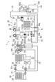
本実施形態は、図1において、冷媒回収装置(30)に冷媒回収容器(100)を接続して構成された冷媒回収容器付き回収装置(10)を用いて、冷媒被回収機(20)から冷媒回収容器(100)に冷媒を回収する冷媒回収システム(1)の全体構成を示したものである。 In this embodiment, in FIG. 1, a recovery device (10) with a refrigerant recovery container configured by connecting a refrigerant recovery container (100) to the refrigerant recovery device (30) is used from the refrigerant recovery machine (20). The overall configuration of the refrigerant recovery system (1) that recovers the refrigerant in the refrigerant recovery container (100) is shown.
〈冷媒被回収機〉
冷媒被回収機(20)は、冷媒回路(21)を有する空調機や冷凍機などの機器である。この冷媒被回収機(20)の冷媒回路(21)は、圧縮機(22)と熱源側熱交換器(23)と受液機(24)と膨張機構(25)と利用側熱交換器(26)とアキュームレータ(27)とが順に接続された閉回路である。この冷媒回路(21)には、冷媒として例えばR32が充填されている。冷媒回路(21)には、液側サービスポート(21a)とガス側サービスポート(21b)が設けられている。また、熱源側熱交換器(23)の近傍には熱源側ファン(23a)が配置され、利用側熱交換器(26)の近傍には利用側ファン(26a)が設けられている。
<Refrigerant recovery machine>
The refrigerant recovery machine (20) is a device such as an air conditioner or a refrigerator having a refrigerant circuit (21). The refrigerant circuit (21) of the refrigerant recovery machine (20) includes a compressor (22), a heat source side heat exchanger (23), a liquid receiver (24), an expansion mechanism (25), and a user side heat exchanger ( It is a closed circuit in which 26) and the accumulator (27) are connected in order. The refrigerant circuit (21) is filled with, for example, R32 as a refrigerant. The refrigerant circuit (21) is provided with a liquid side service port (21a) and a gas side service port (21b). Further, a heat source side fan (23a) is arranged in the vicinity of the heat source side heat exchanger (23), and a user side fan (26a) is provided in the vicinity of the user side heat exchanger (26).
〈冷媒回収容器付き回収装置〉
本実施形態の冷媒回収容器付き回収装置(10)は、上述したように、冷媒回収装置(30)と冷媒回収容器(100)とから構成されている。冷媒回収装置(30)は、冷媒被回収機(20)と冷媒回収容器(100)との間に接続される。
<Recovery device with refrigerant recovery container>
As described above, the recovery device (10) with a refrigerant recovery container of the present embodiment includes the refrigerant recovery device (30) and the refrigerant recovery container (100). The refrigerant recovery device (30) is connected between the refrigerant recovery machine (20) and the refrigerant recovery container (100).
〈冷媒回収装置〉
本実施形態の冷媒回収装置(30)は、上記冷媒被回収機(20)の冷媒回路(21)から冷媒を吸入して圧縮する圧縮機(31)と、該圧縮機(31)から吐出された冷媒を凝縮して上記冷媒回収容器(100)へ送り出す凝縮器(32)とを備えている。
<Refrigerant recovery device>
The refrigerant recovery device (30) of the present embodiment is a compressor (31) that sucks and compresses the refrigerant from the refrigerant circuit (21) of the refrigerant recovery machine (20), and is discharged from the compressor (31). It is equipped with a compressor (32) that condenses the refrigerant and sends it to the refrigerant recovery container (100).
冷媒回収装置(30)は、具体的には以下のように構成されている。 Specifically, the refrigerant recovery device (30) is configured as follows.
まず、この冷媒回収装置(30)は、上記圧縮機(31)及び凝縮器(32)等の機器が収容されたケーシング(35)を備えている。このケーシング(35)には、上記冷媒被回収機(20)がゲージマニホールド(90)を介して接続される吸入口(36)と、上記冷媒回収容器(100)に設けられている後述の液流入ポート(103)が冷媒回収ホース(80)を介して接続される吐出口(37)とが設けられている。 First, the refrigerant recovery device (30) includes a casing (35) in which equipment such as the compressor (31) and the condenser (32) is housed. The casing (35) has a suction port (36) to which the refrigerant recovery machine (20) is connected via a gauge manifold (90), and a liquid described later provided in the refrigerant recovery container (100). An inflow port (103) is provided with a discharge port (37) connected via a refrigerant recovery hose (80).
上記吸入口(36)と圧縮機の吸入ポート(31a)の間には、通路を絞ることで冷媒を減圧する減圧機構となるガス側切換バルブ(41)が接続され、圧縮機(31)の吐出ポート(31a)と凝縮器(32)の間には液側切換バルブ(42)が接続されている。ガス側切換バルブ(41)及び液側切換バルブ(42)は、いずれも三方弁であり、それぞれ図1に黒塗りを施した閉ポートと凝縮器(32)の出口配管(43)との間に、第1冷媒回収配管(44)と第2冷媒回収配管(45)を介して接続されている。第1冷媒回収配管(44)と上記出口配管(43)が接続された第1接続点と、第2冷媒回収配管(45)と上記出口配管(43)とが接続された第2接続点との間には、第1接続点から第2接続点へ向かう冷媒の流通を許容して逆方向への冷媒の流通を禁止する逆止弁(46)が設けられている。上記第1冷媒回収配管(44)により、後述の分岐経路(76)が形成されている。 A gas side switching valve (41), which is a decompression mechanism for reducing the pressure of the refrigerant by narrowing the passage, is connected between the suction port (36) and the suction port (31a) of the compressor. A liquid side switching valve (42) is connected between the discharge port (31a) and the condenser (32). The gas side switching valve (41) and the liquid side switching valve (42) are both three-way valves, and are between the closed port black-painted in FIG. 1 and the outlet pipe (43) of the condenser (32), respectively. Is connected to the first refrigerant recovery pipe (44) via the second refrigerant recovery pipe (45). The first connection point where the first refrigerant recovery pipe (44) and the outlet pipe (43) are connected, and the second connection point where the second refrigerant recovery pipe (45) and the outlet pipe (43) are connected. A check valve (46) is provided between them to allow the flow of the refrigerant from the first connection point to the second connection point and prohibit the flow of the refrigerant in the opposite direction. A branch path (76) described later is formed by the first refrigerant recovery pipe (44).
ガス側切換バルブ(41)及び液側切換バルブ(42)は、それぞれ、流路の切り換えと流量調整が可能な切換バルブである。そして、この冷媒回収装置(30)には、ガス側切換バルブ(41)及び液側切換バルブ(42)を操作する1つの操作部(図示せず)が設けられている。操作部は、例えばダイヤル状のつまみで構成することができ、基準位置から一方向(例えば時計回り方向)へ回転させると冷媒被回収機(20)からガス冷媒の回収(ガス回収)を行うとともに流量を徐々に絞ることができ、逆方向(例えば反時計回り方向)へ回転させると冷媒被回収機(20)から液冷媒の回収(液回収)を行うとともに流量を徐々に絞ることができる。液回収の時はガス回収の時よりも絞り量が大きくなる。また、上記操作部は、凝縮器(32)に残った残留冷媒を回収する残留冷媒回収動作(セルフクリーニング)を行う際に、ガス側切換バルブ(41)を絞り込む操作も可能に構成されている。 The gas side switching valve (41) and the liquid side switching valve (42) are switching valves capable of switching the flow path and adjusting the flow rate, respectively. The refrigerant recovery device (30) is provided with one operation unit (not shown) for operating the gas side switching valve (41) and the liquid side switching valve (42). The operation unit can be composed of, for example, a dial-shaped knob, and when rotated in one direction (for example, clockwise) from the reference position, the gas refrigerant is recovered (gas recovery) from the refrigerant recovery machine (20). The flow rate can be gradually reduced, and when rotated in the opposite direction (for example, in the counterclockwise direction), the liquid refrigerant can be recovered (liquid recovery) from the refrigerant recovery machine (20) and the flow rate can be gradually reduced. When recovering the liquid, the amount of drawing is larger than when recovering the gas. Further, the operation unit is configured to be able to narrow down the gas side switching valve (41) when performing a residual refrigerant recovery operation (self-cleaning) for recovering the residual refrigerant remaining in the condenser (32). ..
冷媒回収装置(30)は、吸引圧力ゲージ(81)と吐出圧力ゲージ(82)を備えている。また、圧縮機(31)の吐出側には高圧遮断スイッチ(83)が設けられ、圧縮機(31)の吸入側には低圧遮断スイッチ(84)が設けられている。高圧遮断スイッチ(83)は、圧縮機(31)の吐出圧力が設定高圧圧力(例えば冷媒回収容器(100)の許容圧力に基づいて定められる圧力。飽和圧力が比較的低い冷媒を用いる冷媒回路の設計圧力に基づいて定められることが多い。)に達すると圧縮機(31)を停止させ、吐出圧力が過度に高くなるのを防ぐスイッチである。低圧遮断スイッチ(84)は、圧縮機(31)の吸入圧力が設定低圧圧力に達すると圧縮機(31)を停止させ、吸入圧力が過度に低くなるのを防ぐスイッチである。低圧遮断スイッチ(84)は、その「有効」と「無効」を切り換える操作部が冷媒回収装置(30)に設けられているスイッチで、冷媒回収時、基本的には「有効」にし、冷媒回収運転が自動で終了するようにしている。ただし、冷媒回収運転の開始時等、過渡的に低圧が低下する場合は「無効」にし、冷媒回収装置(30)が停止するのを防止するようにしてもよい。 The refrigerant recovery device (30) includes a suction pressure gauge (81) and a discharge pressure gauge (82). Further, a high pressure cutoff switch (83) is provided on the discharge side of the compressor (31), and a low pressure cutoff switch (84) is provided on the suction side of the compressor (31). The high-pressure cutoff switch (83) is a pressure determined based on the set high-pressure pressure (for example, the allowable pressure of the refrigerant recovery container (100)) in which the discharge pressure of the compressor (31) is set. It is a switch that stops the compressor (31) when it reaches (often determined based on the design pressure) to prevent the discharge pressure from becoming excessively high. The low pressure cutoff switch (84) is a switch that stops the compressor (31) when the suction pressure of the compressor (31) reaches a set low pressure to prevent the suction pressure from becoming excessively low. The low-voltage cutoff switch (84) is a switch in which the operation unit for switching between "valid" and "invalid" is provided in the refrigerant recovery device (30). When recovering the refrigerant, it is basically set to "valid" and the refrigerant is recovered. The operation is automatically terminated. However, when the low pressure drops transiently, such as at the start of the refrigerant recovery operation, it may be disabled to prevent the refrigerant recovery device (30) from stopping.
上記凝縮器(32)に接続された出口配管(43)には、後述する主冷媒経路(70)と分岐経路(76)の分岐点の上流側に、冷媒を冷却する補助熱交換器(47)を接続可能な補助熱交換器接続ポート(48a,48b)が設けられている。補助熱交換器接続ポート(48a,48b)は、入口側接続ポート(48a)と出口側接続ポート(48b)とから構成されている。また、上記出口配管(43)には、入口側接続ポート(48a)と出口側接続ポート(48b)の間に開閉弁(49)が設けられている。 The outlet pipe (43) connected to the condenser (32) has an auxiliary heat exchanger (47) that cools the refrigerant on the upstream side of the branch point of the main refrigerant path (70) and the branch path (76), which will be described later. ) Is provided with auxiliary heat exchanger connection ports (48a, 48b). The auxiliary heat exchanger connection ports (48a, 48b) are composed of an inlet side connection port (48a) and an outlet side connection port (48b). Further, the outlet pipe (43) is provided with an on-off valve (49) between the inlet side connection port (48a) and the outlet side connection port (48b).
上記補助熱交換器(47)は、例えば、水が流通する開口を有する円筒状容器の中に冷却コイルが収納された水冷凝縮器であり、冷媒流入管(47a)と冷媒流出管(47b)とを有している。そして、冷媒流入管(47a)が入口側接続ポート(48a)に接続され、冷媒流出管(47b)が出口側接続ポート(48b)に接続されている。この補助熱交換器(47)は、水を溜めた貯留容器内で水に浸漬して用いられ、冷却コイル内を冷媒が流れることにより冷媒を冷却する熱交換器である。使用中に貯留容器の水の温度が上昇すると、水を交換すればよい。 The auxiliary heat exchanger (47) is, for example, a water-cooled condenser in which a cooling coil is housed in a cylindrical container having an opening through which water flows, and is a refrigerant inflow pipe (47a) and a refrigerant outflow pipe (47b). And have. Then, the refrigerant inflow pipe (47a) is connected to the inlet side connection port (48a), and the refrigerant outflow pipe (47b) is connected to the outlet side connection port (48b). This auxiliary heat exchanger (47) is a heat exchanger that is used by immersing it in water in a storage container that stores water, and cools the refrigerant by flowing the refrigerant through the cooling coil. If the temperature of the water in the storage container rises during use, the water may be replaced.
〈冷媒回収経路〉
本実施形態の冷媒回収システム(1)は、各機器が、冷媒吸入経路(75)、主冷媒回収経路(70)、及び残留冷媒回収経路(73)で接続されている。
<Refrigerant recovery route>
In the refrigerant recovery system (1) of the present embodiment, each device is connected by a refrigerant suction path (75), a main refrigerant recovery path (70), and a residual refrigerant recovery path (73).
冷媒吸入経路(75)は、上記冷媒被回収機(20)と上記吸入口(36)との間に上記ゲージマニホールド(90)を接続して形成される経路である。 The refrigerant suction path (75) is a path formed by connecting the gauge manifold (90) between the refrigerant recovery machine (20) and the suction port (36).
主冷媒回収経路(70)は、上記吸入口(36)から、上記ガス側切換バルブ(41)、上記圧縮機(31)、上記液側切換バルブ(42)、上記凝縮器(32)、補助熱交換器(47)、逆止弁(46)、及び吐出口(37)を介して上記冷媒回収容器(100)に至る経路である。 The main refrigerant recovery path (70) is from the suction port (36) to the gas side switching valve (41), the compressor (31), the liquid side switching valve (42), the condenser (32), and the auxiliary. This is a route leading to the refrigerant recovery container (100) via the heat exchanger (47), the check valve (46), and the discharge port (37).
残留冷媒回収経路(73)は、凝縮器(32)の流入側を液側切換バルブ(42)で閉鎖した図3の状態で形成される経路であり、上記凝縮器(32)、補助熱交換器(47)、分岐経路(73)、ガス側切換バルブ(41)、圧縮機(31)、液側切換バルブ(42)、及び吐出口(37)を介して上記冷媒回収容器(100)に至る経路である。 The residual refrigerant recovery path (73) is a path formed in the state of FIG. 3 in which the inflow side of the condenser (32) is closed by the liquid side switching valve (42), and the condenser (32) and the auxiliary heat exchange To the refrigerant recovery container (100) via the vessel (47), branch path (73), gas side switching valve (41), compressor (31), liquid side switching valve (42), and discharge port (37). It is the route to reach.
〈冷媒回収容器〉
冷媒回収容器(100)は、冷媒を溜める容器本体(101)に、その容器本体(101)内のガス冷媒が流出可能なガス流出ポート(102)と、上記冷媒回収装置(30)の凝縮器(32)から送り出された液冷媒を容器本体(101)へ導入する液流入ポート(103)とを設けたものである。ガス流出ポート(102)にはガス流出バルブ(102a)が、液流入ポート(103)には液流入バルブ(103a)が設けられている。ガス流出バルブ(102a)及び液流入バルブ(103a)各ポート(102,103)を開閉するバルブである。
<Refrigerant recovery container>
The refrigerant recovery container (100) has a container body (101) for storing refrigerant, a gas outflow port (102) through which the gas refrigerant in the container body (101) can flow out, and a condenser of the refrigerant recovery device (30). It is provided with a liquid inflow port (103) for introducing the liquid refrigerant sent out from (32) into the container body (101). The gas outflow port (102) is provided with a gas outflow valve (102a), and the liquid inflow port (103) is provided with a liquid inflow valve (103a). A valve that opens and closes each port (102, 103) of the gas outflow valve (102a) and the liquid inflow valve (103a).
冷媒回収容器(100)には、容器本体(101)内に溜まる液冷媒の液面高さを冷媒回収装置(30)で検知するためのフロートセンサ(105)が設けられている。フロートセンサ(105)のフロートが所定高さになると液冷媒の貯留量が規定量に達したと判断して冷媒回収装置(30)が停止するようになっている。 The refrigerant recovery container (100) is provided with a float sensor (105) for detecting the liquid level height of the liquid refrigerant accumulated in the container body (101) with the refrigerant recovery device (30). When the float of the float sensor (105) reaches a predetermined height, it is determined that the stored amount of the liquid refrigerant has reached the specified amount, and the refrigerant recovery device (30) is stopped.
図示していないが、容器本体(101)の上面やガス流出ポート(102)には可溶栓(図示せず)が設けられている。可溶栓は、冷媒回収容器(100)の周囲温度が上昇したときに、該回収容器(100)の内部圧力が過度に上昇するのを防止するためのガス抜きとして設けられている。 Although not shown, a fusible plug (not shown) is provided on the upper surface of the container body (101) and the gas outflow port (102). The fusible plug is provided as a gas vent to prevent the internal pressure of the recovery container (100) from rising excessively when the ambient temperature of the refrigerant recovery container (100) rises.
〈ゲージマニホールド〉
ゲージマニホールド(90)は、従来から一般的に用いられている圧力ゲージ付きのマニホールドであり、高圧バルブ側ポート(91)、低圧バルブ側ポート(92)、真空ポンプ側ポート(93)、及びエアパージポート(94)を有している。
<Gauge manifold>
The gauge manifold (90) is a manifold with a pressure gauge that has been generally used in the past, and is a high pressure valve side port (91), a low pressure valve side port (92), a vacuum pump side port (93), and an air purge. It has a port (94).
ゲージマニホールド(90)の高圧バルブ側ポート(91)は、冷媒被回収機(20)の液側サービスポート(21a)に接続されている。ゲージマニホールド(90)の低圧バルブ側ポート(92)は、冷媒被回収機(20)のガス側サービスポート(21b)に接続されている。ゲージマニホールド(90)の真空ポンプ側ポート(93)は、フィルタ(95)を介して冷媒回収装置(30)の吸入口(36)に接続されている。ゲージマニホールド(90)には、この実施形態では使用していないが、エアパージポート(94)も設けられている。 The high pressure valve side port (91) of the gauge manifold (90) is connected to the liquid side service port (21a) of the refrigerant recovery machine (20). The low pressure valve side port (92) of the gauge manifold (90) is connected to the gas side service port (21b) of the refrigerant recovery machine (20). The vacuum pump side port (93) of the gauge manifold (90) is connected to the suction port (36) of the refrigerant recovery device (30) via the filter (95). Although not used in this embodiment, the gauge manifold (90) is also provided with an air purge port (94).
ゲージマニホールド(90)は、ガス回収の時は、低圧側バルブ(ガス側バルブ)(92a)が開かれる。液ガス同時回収の時は、高圧側バルブ(液側バルブ)(91a)と低圧側バルブ(92a)の両方が開かれる。また、ゲージマニホールド(90)は、低圧ゲージ(92b)と高圧ゲージ(91b)を有している。 The low pressure side valve (gas side valve) (92a) of the gauge manifold (90) is opened at the time of gas recovery. At the time of simultaneous recovery of liquid gas, both the high pressure side valve (liquid side valve) (91a) and the low pressure side valve (92a) are opened. Further, the gauge manifold (90) has a low pressure gauge (92b) and a high pressure gauge (91b).
−運転動作−
次に、上記冷媒被回収機(20)の冷媒回路(21)から、上記冷媒回収装置(30)が有する圧縮機(31)に冷媒を吸入して圧縮し、該冷媒回収装置(30)が有する凝縮器(32)で凝縮した冷媒を上記冷媒回収容器(100)へ送り出すことにより、上記冷媒回収容器(100)に冷媒を回収する冷媒回収方法について説明する。
-Driving operation-
Next, the refrigerant is sucked from the refrigerant circuit (21) of the refrigerant recovery machine (20) into the compressor (31) of the refrigerant recovery device (30) and compressed, and the refrigerant recovery device (30) A refrigerant recovery method for recovering the refrigerant in the refrigerant recovery container (100) by sending the refrigerant condensed by the condenser (32) to the refrigerant recovery container (100) will be described.
本実施形態では、運転準備を行った後、下記の第1冷媒回収工程と第2冷媒回収工程とが順に行われる。第1冷媒回収工程において、冷媒は冷媒被回収機(20)から、液ガス混合状態またはガス状態で冷媒回収装置(30)の圧縮機(31)に吸入される。 In the present embodiment, after the operation preparation is performed, the following first refrigerant recovery step and second refrigerant recovery step are performed in order. In the first refrigerant recovery step, the refrigerant is sucked from the refrigerant recovery machine (20) into the compressor (31) of the refrigerant recovery device (30) in a liquid-gas mixed state or a gas state.
運転準備の段階では、ゲージマニホールド(90)の液側バルブ(91a)とガス側バルブ(92a)が「開」に切り換えられる。冷媒回収装置(30)のガス側切換バルブ(41)は、吸入口(36)側のポートと圧縮機(31)側のポートが連通し、分岐経路(76)側のポートが閉鎖される(連通側が白抜き、閉鎖側が黒塗り。以下同様)。液側切換バルブ(42)は、圧縮機(31)側のポートと凝縮器(32)側のポートが連通し、残留冷媒回収経路(73)側のポートが閉鎖される。ガス側切換バルブ(41)は、運転時に冷媒被回収機(20)から冷媒が急激に圧縮機(31)へ回収されない開度に設定される。開閉弁(49)は基本的には「閉」状態となるが、補助熱交換器(47)を使わないときは「開」に設定される。
また、冷媒回収容器(100)では、ガス流出バルブ(102a)及び液流入バルブ(103a)の両方が開かれる。運転準備の際、冷媒被回収機(20)において液冷媒を加熱して蒸発を促進しておくとよい。
At the stage of preparation for operation, the liquid side valve (91a) and the gas side valve (92a) of the gauge manifold (90) are switched to "open". In the gas side switching valve (41) of the refrigerant recovery device (30), the port on the suction port (36) side and the port on the compressor (31) side communicate with each other, and the port on the branch path (76) side is closed ( The communication side is outlined and the closed side is painted black. The same applies below). In the liquid side switching valve (42), the port on the compressor (31) side and the port on the condenser (32) side communicate with each other, and the port on the residual refrigerant recovery path (73) side is closed. The gas side switching valve (41) is set to an opening degree at which the refrigerant is not suddenly collected from the refrigerant recovery machine (20) to the compressor (31) during operation. The on-off valve (49) is basically in the "closed" state, but is set to "open" when the auxiliary heat exchanger (47) is not used.
Further, in the refrigerant recovery container (100), both the gas outflow valve (102a) and the liquid inflow valve (103a) are opened. When preparing for operation, it is advisable to heat the liquid refrigerant in the refrigerant recovery machine (20) to promote evaporation.
〈第1冷媒回収工程〉
図2に示すように、第1冷媒回収工程では、冷媒被回収機(20)から冷媒吸入経路(75)を介して冷媒回収装置(30)の圧縮機(31)へ冷媒を吸入するとともに、冷媒を圧縮機(31)及び凝縮器(32)を介して上記冷媒回収容器(100)に設けられている液流入ポート(103)から該冷媒回収容器(100)の容器本体(101)内に回収する。
<First refrigerant recovery process>
As shown in FIG. 2, in the first refrigerant recovery step, the refrigerant is sucked from the refrigerant recovery machine (20) to the compressor (31) of the refrigerant recovery device (30) via the refrigerant suction path (75), and at the same time. The refrigerant is transferred from the liquid inflow port (103) provided in the refrigerant recovery container (100) into the container body (101) of the refrigerant recovery container (100) via the compressor (31) and the condenser (32). to recover.
この第1冷媒回収工程では、冷媒被回収機(20)からゲージマニホールド(90)を介して冷媒が圧縮機(31)に吸入され、圧縮機(31)から吐出された冷媒が凝縮器(32)で凝縮し、冷媒回収容器(100)へ流入する。したがって、冷媒回収容器(100)の冷媒の貯留量が増えていく。 In this first refrigerant recovery step, the refrigerant is sucked into the compressor (31) from the refrigerant recovery machine (20) via the gauge manifold (90), and the refrigerant discharged from the compressor (31) is the condenser (32). ) Condenses and flows into the refrigerant recovery container (100). Therefore, the amount of refrigerant stored in the refrigerant recovery container (100) increases.
このとき、凝縮器(32)から流出した冷媒は補助熱交換器(47)で冷却される。したがって、冷媒の冷却効果が高められ、冷媒回収容器(100)内の圧力上昇が抑えられる。 At this time, the refrigerant flowing out of the condenser (32) is cooled by the auxiliary heat exchanger (47). Therefore, the cooling effect of the refrigerant is enhanced, and the pressure rise in the refrigerant recovery container (100) is suppressed.
冷媒被回収機(20)の冷媒がほぼ回収されると、ゲージマニホールド(90)の低圧ゲージ(92b)と高圧ゲージ(91b)、及び冷媒回収装置(30)の吸引圧力ゲージ(81)と吐出圧力ゲージ(82)に示される圧力がそれぞれ所定値に達する。そうすると、圧縮機(31)が一旦停止し、第1冷媒回収行程が終了する。 When the refrigerant of the refrigerant recovery machine (20) is almost recovered, the low pressure gauge (92b) and the high pressure gauge (91b) of the gauge manifold (90), and the suction pressure gauge (81) and the discharge of the refrigerant recovery device (30). The pressure indicated on the pressure gauge (82) reaches a predetermined value. Then, the compressor (31) is temporarily stopped, and the first refrigerant recovery process is completed.
〈第2冷媒回収工程〉
第1冷媒回収工程が終了すると、冷媒回収装置(30)の凝縮器(32)に冷媒が残留した状態になっている。そこで、次に凝縮器(32)の残留冷媒を回収する第2冷媒回収工程が行われる。
<Second refrigerant recovery process>
When the first refrigerant recovery step is completed, the refrigerant remains in the condenser (32) of the refrigerant recovery device (30). Therefore, a second refrigerant recovery step of recovering the residual refrigerant of the condenser (32) is then performed.
第2冷媒回収工程は、上記凝縮器(32)から上記圧縮機(31)を介して上記冷媒回収容器(100)へ冷媒を回収する工程である。第2冷媒回収工程を開始するに当たり、冷媒回収装置(30)のガス側切換バルブ(41)は、吸入口(36)側のポートが閉鎖され、圧縮機(31)側のポートと分岐経路(76)側のポートが連通する。液側切換バルブ(42)は、圧縮機(31)側のポートと残留冷媒回収経路(73)側のポートが連通し、凝縮器(32)側のポートが閉鎖される。 The second refrigerant recovery step is a step of recovering the refrigerant from the condenser (32) to the refrigerant recovery container (100) via the compressor (31). At the start of the second refrigerant recovery process, the gas side switching valve (41) of the refrigerant recovery device (30) has the suction port (36) side port closed, and the compressor (31) side port and branch path ( 76) The port on the side communicates. In the liquid side switching valve (42), the port on the compressor (31) side and the port on the residual refrigerant recovery path (73) side communicate with each other, and the port on the condenser (32) side is closed.
この第2冷媒回収工程は、具体的には、上記第1冷媒回収工程の完了後に上記圧縮機(31)を再起動し、上記ガス流出ポート(102)を閉鎖した状態で、上記凝縮器(32)内に残留した冷媒を上記圧縮機(31)で吸入して上記冷媒回収容器(100)へ送り出す図3の冷媒回収動作(セルフクリーニング)を行う工程である。図3の冷媒回収動作では、液側切換バルブ(42)の凝縮器(32)側のポートが閉じ、ガス側切換バルブ(41)の分岐経路(76)側のポートと圧縮機(31)側のポートとが連通した状態で圧縮機(31)が運転される。このとき、ガス側切換バルブ(41)を、吸引圧力ゲージ(81)がほぼ真空域に近い低圧圧力になるまで絞り込んで凝縮器(34)から圧縮機(31)へ残留冷媒を吸引して加圧し、液側切換バルブ(42)及び残留冷媒回収経路(73)を介して冷媒を冷媒回収容器(100)に回収する。 Specifically, in the second refrigerant recovery step, after the completion of the first refrigerant recovery step, the compressor (31) is restarted, and the gas outflow port (102) is closed. This is a step of performing the refrigerant recovery operation (self-cleaning) of FIG. 3 in which the refrigerant remaining in 32) is sucked by the compressor (31) and sent out to the refrigerant recovery container (100). In the refrigerant recovery operation of FIG. 3, the port on the condenser (32) side of the liquid side switching valve (42) is closed, and the port on the branch path (76) side and the compressor (31) side of the gas side switching valve (41). The compressor (31) is operated in a state where it communicates with the port of. At this time, the gas side switching valve (41) is narrowed down until the suction pressure gauge (81) reaches a low pressure pressure close to the vacuum range, and the residual refrigerant is sucked from the condenser (34) to the compressor (31) and added. It is compressed and the refrigerant is recovered in the refrigerant recovery container (100) via the liquid side switching valve (42) and the residual refrigerant recovery path (73).
図3の動作中に、吸引圧力が所定値よりも低下して実質的に真空になると、圧縮機(31)が停止する。その後、ガス側切換バルブ(41)及び液側切換バルブ(42)が閉鎖されるとともに、冷媒回収容器(100)の液流入ポート(103)が閉じられて冷媒回収(80)が装置(10)から取り外されて、冷媒回収工程がすべて終了する。 During the operation of FIG. 3, when the suction pressure drops below a predetermined value and becomes substantially a vacuum, the compressor (31) stops. After that, the gas side switching valve (41) and the liquid side switching valve (42) are closed, and the liquid inflow port (103) of the refrigerant recovery container (100) is closed, and the refrigerant recovery (80) is the device (10). The refrigerant recovery process is completed.
本実施形態では、第2冷媒回収工程を行うことで、補助熱交換器(47)の冷媒も圧縮機(31)から残留冷媒回収経路(73)を通って冷媒回収容器(100)に回収される。つまり、本実施形態の構成を採用することにより、補助熱交換器(47)から冷媒を回収する作業を別に行うことなく、冷媒被回収機(100)の冷媒を残さずに効率よく回収できる。 In the present embodiment, by performing the second refrigerant recovery step, the refrigerant of the auxiliary heat exchanger (47) is also recovered from the compressor (31) to the refrigerant recovery container (100) through the residual refrigerant recovery path (73). To. That is, by adopting the configuration of the present embodiment, it is possible to efficiently recover the refrigerant of the refrigerant recovery machine (100) without leaving the refrigerant of the refrigerant recovery machine (100) without separately performing the work of recovering the refrigerant from the auxiliary heat exchanger (47).
−実施形態の効果−
本実施形態によれば、補助熱交換器(47)を用いる構成において、冷媒回収時に冷媒が補助熱交換器(47)内に残るのを抑制できるから冷媒の回収効率が低下するのを抑制できる。また、補助熱交換器(47)内の冷媒を回収する作業を別途行わなくてもよいので、冷媒回収の作業効率が低下するのも抑制できる。さらに、従来と同様の冷却コイルなどの補助熱交換器(47)を用いることができるから、冷媒の回収効率や作業効率の低下を抑制する構成を容易に実現できる。
-Effect of embodiment-
According to the present embodiment, in the configuration using the auxiliary heat exchanger (47), it is possible to prevent the refrigerant from remaining in the auxiliary heat exchanger (47) at the time of refrigerant recovery, so that it is possible to suppress a decrease in the refrigerant recovery efficiency. .. Further, since it is not necessary to separately perform the work of recovering the refrigerant in the auxiliary heat exchanger (47), it is possible to suppress a decrease in the work efficiency of the refrigerant recovery. Further, since an auxiliary heat exchanger (47) such as a cooling coil similar to the conventional one can be used, a configuration that suppresses a decrease in refrigerant recovery efficiency and work efficiency can be easily realized.
−実施形態の変形例−
〈変形例1〉
図1〜図3の実施形態では、上記凝縮器(32)の出口配管(43)における主冷媒回収経路(70)と分岐経路(76)の分岐点の上流側に、冷媒を冷却する補助熱交換器(47)を接続可能な補助熱交換器接続ポート(48a,48b)を設け、この補助熱交換器接続ポート(48a,48b)に、冷媒回収装置(10)とは別部品である補助熱交換器(47)を接続するようにしているが、上記凝縮器(32)の出口配管(43)における主冷媒回収経路(70)と分岐経路(76)の分岐点の上流側に補助熱交換器(47)を直接に接続し、補助熱交換器(47)を冷媒回収装置(30)と一体の部品にしてもよい。
-Modified example of the embodiment-
<Modification example 1>
In the embodiment of FIGS. 1 to 3, the auxiliary heat for cooling the refrigerant is on the upstream side of the branch point of the main refrigerant recovery path (70) and the branch path (76) in the outlet pipe (43) of the condenser (32). Auxiliary heat exchanger connection ports (48a, 48b) to which the exchanger (47) can be connected are provided, and the auxiliary heat exchanger connection ports (48a, 48b) are auxiliary parts separate from the refrigerant recovery device (10). Although the heat exchanger (47) is connected, the auxiliary heat is upstream of the branch point of the main refrigerant recovery path (70) and the branch path (76) in the outlet pipe (43) of the condenser (32). The exchanger (47) may be directly connected and the auxiliary heat exchanger (47) may be an integral part of the refrigerant recovery device (30).
このように構成しても、図1の実施形態と同様の効果を奏することが可能である。 Even with this configuration, it is possible to achieve the same effect as that of the embodiment of FIG.
〈変形例2〉
上記補助熱交換器(47)は、凝縮器(32)の出口配管(43)を図4,5に示す変形例2のように構成して、冷媒回収装置(30)に着脱するようにしてもよい。図4は補助熱交換器(47)を冷媒回収装置(30)から取り外した状態を示す図、図5は補助熱交換器(47)を冷媒回収装置(30)に取り付けた状態を示す図である。
<Modification 2>
In the auxiliary heat exchanger (47), the outlet pipe (43) of the condenser (32) is configured as shown in the second modification shown in FIGS. 4 and 5, so that the auxiliary heat exchanger (47) can be attached to and detached from the refrigerant recovery device (30). May be good. FIG. 4 is a diagram showing a state in which the auxiliary heat exchanger (47) is removed from the refrigerant recovery device (30), and FIG. 5 is a diagram showing a state in which the auxiliary heat exchanger (47) is attached to the refrigerant recovery device (30). is there.
この変形例2では、凝縮器(32)の出口配管(43)には、2つの接続継手(50a,50b)が設けられている。冷媒回収時に補助熱交換器(47)を使用しない図4の状態では、両接続継手(50a,50b)の間に接続配管(51)が取り付けられる。一方、冷媒回収時に補助熱交換器(47)を使用するときは、図4に示した接続配管(51)を各接続継手(50a,50b)から取り外し、各接続継手(50a,50b)に補助熱交換器(47)の冷媒流入管(47a)と冷媒流出管(47b)を取り付ける。 In this modification 2, the outlet pipe (43) of the condenser (32) is provided with two connection joints (50a and 50b). In the state of FIG. 4 in which the auxiliary heat exchanger (47) is not used when recovering the refrigerant, the connecting pipe (51) is attached between the two connecting joints (50a and 50b). On the other hand, when using the auxiliary heat exchanger (47) when recovering the refrigerant, the connection pipe (51) shown in FIG. 4 is removed from each connection joint (50a, 50b) and assisted in each connection joint (50a, 50b). Install the refrigerant inflow pipe (47a) and the refrigerant outflow pipe (47b) of the heat exchanger (47).
このように構成しても、補助熱交換器(47)を冷媒回収装置(30)に取り付ける構成を容易に実現できる。また、補助熱交換器(47)を用いて冷媒回収をする際には、図1〜図3の上記実施形態と同様、冷媒の回収効率や作業効率の低下を抑制することができる。 Even with this configuration, it is possible to easily realize a configuration in which the auxiliary heat exchanger (47) is attached to the refrigerant recovery device (30). Further, when the refrigerant is recovered by using the auxiliary heat exchanger (47), it is possible to suppress a decrease in the refrigerant recovery efficiency and the work efficiency as in the above-described embodiment of FIGS. 1 to 3.
《その他の実施形態》
上記実施形態については、以下のような構成としてもよい。
<< Other Embodiments >>
The above embodiment may have the following configuration.
例えば、本発明の冷媒回収装置(30)は、上記実施形態で説明したR32の他にもR410Aなどのように冷凍サイクルの設計高圧圧力が比較的高い冷媒に対して冷媒回収容器(100)の圧力の上昇を抑えられる点で適しているが、適用対象の冷媒被回収機の冷媒をこれらに限定するものではない。 For example, the refrigerant recovery device (30) of the present invention has a refrigerant recovery container (100) for a refrigerant having a relatively high design high pressure in a refrigeration cycle, such as R410A, in addition to R32 described in the above embodiment. It is suitable in that the increase in pressure can be suppressed, but the refrigerant of the refrigerant recovery machine to be applied is not limited to these.
なお、以上の実施形態は、本質的に好ましい例示であって、本発明、その適用物、あるいはその用途の範囲を制限することを意図するものではない。 It should be noted that the above embodiments are essentially preferred examples and are not intended to limit the scope of the present invention, its applications, or its uses.
以上説明したように、本発明は、空調機や冷凍機などの冷媒被回収機の冷媒回路から冷媒を吸入し、液化して冷媒回収容器へ吐出する冷媒回収装置について有用である。 As described above, the present invention is useful for a refrigerant recovery device that sucks refrigerant from a refrigerant circuit of a refrigerant recovery machine such as an air conditioner or a refrigerator, liquefies it, and discharges it to a refrigerant recovery container.
1 冷媒回収システム
10 冷媒回収容器付き回収装置
20 冷媒被回収機
21 冷媒回路
30 冷媒回収装置
31 圧縮機
32 凝縮器
41 ガス側切換バルブ(減圧機構)
47 水冷凝縮器(補助熱交換器)
48a 入口側接続ポート(補助熱交換器接続ポート)
48b 出口側接続ポート(補助熱交換器接続ポート)
70 主冷媒回収経路
75 冷媒吸入経路
76 分岐経路
77 残留冷媒回収経路
100 冷媒回収容器
1 Refrigerant recovery system
10 Recovery device with refrigerant recovery container
20 Refrigerant recovery machine
21 Refrigerant circuit
30 Refrigerant recovery device
31 compressor
32 condenser
41 Gas side switching valve (decompression mechanism)
47 Water-cooled condenser (auxiliary heat exchanger)
48a Inlet side connection port (auxiliary heat exchanger connection port)
48b Outlet side connection port (auxiliary heat exchanger connection port)
70 Main refrigerant recovery route
75 Refrigerant suction path
76 Branch route
77 Residual refrigerant recovery route
100 Refrigerant recovery container
Claims (3)
上記冷媒被回収機(20)の冷媒回路(21)から冷媒吸入経路(75)を介して冷媒を吸入し、圧縮する圧縮機(31)と、該圧縮機(31)から吐出された冷媒を凝縮し、主冷媒回収経路(70)を介して上記冷媒回収容器(100)へ送り出す凝縮器(32)と、該主冷媒回収経路(70)から分岐した分岐経路(76)の減圧機構(41)で凝縮器(32)の残留冷媒を減圧して圧縮機(31)で吸入し、加圧して上記冷媒回収容器(100)へ送り出す残留冷媒回収経路(77)と、を備え、
上記凝縮器(32)の出口側には、主冷媒回収経路(70)と分岐経路(76)の分岐点の上流側に、冷媒を冷却する補助熱交換器(47)を接続可能な補助熱交換器接続ポート(48a,48b)が設けられ、
上記冷媒被回収機(20)の冷媒が上記圧縮機(31)、上記凝縮器(32)、及び上記補助熱交換器接続ポート(48a,48b)に接続される補助熱交換器(47)を通って上記冷媒回収容器(100)へ流れる冷媒の流れと、上記凝縮器(32)の冷媒が上記補助熱交換器(47)、上記減圧機構(41)、及び上記圧縮機(31)を通って上記冷媒回収容器(100)へ流れる冷媒の流れとを切り換える切換バルブ(41,42)を備えていることを特徴とする冷媒回収装置。 A refrigerant recovery device connected between the refrigerant recovery machine (20) and the refrigerant recovery container (100).
A compressor (31) that sucks and compresses the refrigerant from the refrigerant circuit (21) of the refrigerant recovery machine (20) via the refrigerant suction path (75) and the refrigerant discharged from the compressor (31). A condenser (32) that condenses and sends it to the refrigerant recovery container (100) via the main refrigerant recovery path (70), and a decompression mechanism (41) of a branch path (76) branched from the main refrigerant recovery path (70). ) Depressurizes the residual refrigerant in the condenser (32), sucks it in with the compressor (31), pressurizes it, and sends it out to the refrigerant recovery container (100).
Auxiliary heat to which an auxiliary heat exchanger (47) for cooling the refrigerant can be connected to the upstream side of the branch point of the main refrigerant recovery path (70) and the branch path (76) on the outlet side of the condenser (32). Exchange connection ports (48a, 48b) are provided ,
Auxiliary heat exchangers (47) in which the refrigerant of the refrigerant recovery machine (20) is connected to the compressor (31), the condenser (32), and the auxiliary heat exchanger connection ports (48a, 48b). The flow of the refrigerant flowing through the refrigerant recovery container (100) and the refrigerant of the condenser (32) pass through the auxiliary heat exchanger (47), the decompression mechanism (41), and the compressor (31). The refrigerant recovery device is provided with a switching valve (41, 42) for switching the flow of the refrigerant flowing into the refrigerant recovery container (100) .
上記冷媒被回収機(20)の冷媒回路(21)から冷媒吸入経路(75)を介して冷媒を吸入し、圧縮する圧縮機(31)と、該圧縮機(31)から吐出された冷媒を凝縮し、主冷媒回収経路(70)を介して上記冷媒回収容器(100)へ送り出す凝縮器(32)と、該主冷媒回収経路(70)から分岐した分岐経路(76)の減圧機構(41)で凝縮器(32)の残留冷媒を減圧して圧縮機(31)で吸入し、加圧して上記冷媒回収容器(100)へ送り出す残留冷媒回収経路(77)と、を備え、
上記凝縮器(32)の出口側には、主冷媒回収経路(70)と分岐経路(76)の分岐点の上流側に、冷媒を冷却する補助熱交換器(47)が接続され、
上記冷媒被回収機(20)の冷媒が上記圧縮機(31)、上記凝縮器(32)、及び上記補助熱交換器(47)を通って上記冷媒回収容器(100)へ流れる冷媒の流れと、上記凝縮器(32)の冷媒が上記補助熱交換器(47)、上記減圧機構(41)、及び上記圧縮機(31)を通って上記冷媒回収容器(100)へ流れる冷媒の流れとを切り換える切換バルブ(41,42)を備えていることを特徴とする冷媒回収装置。 A refrigerant recovery device connected between the refrigerant recovery machine (20) and the refrigerant recovery container (100).
A compressor (31) that sucks and compresses the refrigerant from the refrigerant circuit (21) of the refrigerant recovery machine (20) via the refrigerant suction path (75) and the refrigerant discharged from the compressor (31). A condenser (32) that condenses and sends it to the refrigerant recovery container (100) via the main refrigerant recovery path (70), and a decompression mechanism (41) of a branch path (76) branched from the main refrigerant recovery path (70). ) Depressurizes the residual refrigerant in the condenser (32), sucks it in with the compressor (31), pressurizes it, and sends it out to the refrigerant recovery container (100).
An auxiliary heat exchanger (47) for cooling the refrigerant is connected to the outlet side of the condenser (32) on the upstream side of the branch point of the main refrigerant recovery path (70) and the branch path (76) .
With the flow of the refrigerant flowing from the refrigerant recovery machine (20) to the refrigerant recovery container (100) through the compressor (31), the condenser (32), and the auxiliary heat exchanger (47). , The flow of the refrigerant through which the refrigerant of the condenser (32) flows to the refrigerant recovery container (100) through the auxiliary heat exchanger (47), the decompression mechanism (41), and the compressor (31). A refrigerant recovery device characterized by being equipped with a switching valve (41, 42) for switching .
上記補助熱交換器(47)が水冷凝縮器(47)により構成されていることを特徴とする冷媒回収装置。 In claim 1 or 2,
A refrigerant recovery device characterized in that the auxiliary heat exchanger (47) is composed of a water-cooled condenser (47).
Priority Applications (5)
| Application Number | Priority Date | Filing Date | Title |
|---|---|---|---|
| JP2017133800A JP6822335B2 (en) | 2017-07-07 | 2017-07-07 | Refrigerant recovery device |
| CN201880045162.3A CN110869683B (en) | 2017-07-07 | 2018-06-25 | Refrigerant recovery device |
| EP18828007.7A EP3627077A4 (en) | 2017-07-07 | 2018-06-25 | Refrigerant recovery apparatus |
| US16/628,943 US11131489B2 (en) | 2017-07-07 | 2018-06-25 | Refrigerant recovery apparatus |
| PCT/JP2018/023965 WO2019009117A1 (en) | 2017-07-07 | 2018-06-25 | Refrigerant recovery apparatus |
Applications Claiming Priority (1)
| Application Number | Priority Date | Filing Date | Title |
|---|---|---|---|
| JP2017133800A JP6822335B2 (en) | 2017-07-07 | 2017-07-07 | Refrigerant recovery device |
Publications (2)
| Publication Number | Publication Date |
|---|---|
| JP2019015461A JP2019015461A (en) | 2019-01-31 |
| JP6822335B2 true JP6822335B2 (en) | 2021-01-27 |
Family
ID=64950014
Family Applications (1)
| Application Number | Title | Priority Date | Filing Date |
|---|---|---|---|
| JP2017133800A Active JP6822335B2 (en) | 2017-07-07 | 2017-07-07 | Refrigerant recovery device |
Country Status (5)
| Country | Link |
|---|---|
| US (1) | US11131489B2 (en) |
| EP (1) | EP3627077A4 (en) |
| JP (1) | JP6822335B2 (en) |
| CN (1) | CN110869683B (en) |
| WO (1) | WO2019009117A1 (en) |
Families Citing this family (3)
| Publication number | Priority date | Publication date | Assignee | Title |
|---|---|---|---|---|
| EP3745049B1 (en) * | 2019-05-29 | 2024-02-07 | Carrier Corporation | Refrigeration apparatus |
| JP2021173481A (en) * | 2020-04-27 | 2021-11-01 | ダイキン工業株式会社 | Refrigerant recovery control device and refrigerant recovery control system |
| CN113310256B (en) * | 2021-05-19 | 2022-12-06 | 浙江飞越机电有限公司 | Air exhaust structure of refrigerant recycling machine and air exhaust method with air exhaust structure |
Family Cites Families (16)
| Publication number | Priority date | Publication date | Assignee | Title |
|---|---|---|---|---|
| US4476688A (en) * | 1983-02-18 | 1984-10-16 | Goddard Lawrence A | Refrigerant recovery and purification system |
| US4998413A (en) * | 1988-09-01 | 1991-03-12 | Nippondenso Co., Ltd. | Refrigerant recovery system |
| JPH0737869B2 (en) * | 1989-01-26 | 1995-04-26 | 日本電気株式会社 | Cooling system |
| EP0379211A3 (en) * | 1989-01-19 | 1990-10-10 | Nec Corporation | Cooling apparatus |
| JPH0792298B2 (en) * | 1991-10-03 | 1995-10-09 | 三菱重工冷熱機材株式会社 | Refrigerant recovery and regeneration device |
| US5241834A (en) * | 1992-05-18 | 1993-09-07 | Cfc-Tek Inc. | Refrigeration fluid recovery apparatus |
| US5230224A (en) * | 1992-05-28 | 1993-07-27 | Rsb Engineers/Planners, Inc. | Refrigerant recovery system |
| JP3133622B2 (en) * | 1994-09-30 | 2001-02-13 | 三洋電機株式会社 | Refrigerant recovery device |
| US5617731A (en) * | 1995-04-19 | 1997-04-08 | Mainstream Engineering Corporation | Refrigerant recovery/recycling system |
| JP2000055514A (en) * | 1998-08-05 | 2000-02-25 | Toshiba Corp | Compression type refrigerant recovery device |
| JP3109500B2 (en) * | 1998-12-16 | 2000-11-13 | ダイキン工業株式会社 | Refrigeration equipment |
| JP2005344988A (en) | 2004-06-02 | 2005-12-15 | Asada Kk | Cooling medium recovering device for small refrigerating air conditioner |
| EP3767203B1 (en) * | 2012-05-30 | 2022-10-05 | Snap-On Climate Solutions S.R.L. | Apparatus and method for recovering and regenerating a refrigerant from an a/c plant |
| CN203837358U (en) * | 2014-05-27 | 2014-09-17 | 珠海格力电器股份有限公司 | Refrigerant recovery system |
| JP6573523B2 (en) * | 2015-10-06 | 2019-09-11 | 三菱電機ビルテクノサービス株式会社 | Refrigerant recovery device |
| CN106907884B (en) * | 2017-04-01 | 2019-06-11 | 合肥通用机械研究院有限公司 | Test system of compressor is quickly filled with full season refrigerant and recovery system |
-
2017
- 2017-07-07 JP JP2017133800A patent/JP6822335B2/en active Active
-
2018
- 2018-06-25 EP EP18828007.7A patent/EP3627077A4/en active Pending
- 2018-06-25 US US16/628,943 patent/US11131489B2/en active Active
- 2018-06-25 CN CN201880045162.3A patent/CN110869683B/en active Active
- 2018-06-25 WO PCT/JP2018/023965 patent/WO2019009117A1/en unknown
Also Published As
| Publication number | Publication date |
|---|---|
| CN110869683B (en) | 2022-03-11 |
| JP2019015461A (en) | 2019-01-31 |
| EP3627077A1 (en) | 2020-03-25 |
| CN110869683A (en) | 2020-03-06 |
| WO2019009117A1 (en) | 2019-01-10 |
| EP3627077A4 (en) | 2021-03-10 |
| US20200208889A1 (en) | 2020-07-02 |
| US11131489B2 (en) | 2021-09-28 |
Similar Documents
| Publication | Publication Date | Title |
|---|---|---|
| JP6935720B2 (en) | Refrigeration equipment | |
| JP6822335B2 (en) | Refrigerant recovery device | |
| JPH0650639A (en) | Circuit for recovering refrigerant from cooling unit losing function and recovery method | |
| US20150323233A1 (en) | Device and Method for Maintaining an Air Conditioner | |
| JP2004309029A (en) | Refrigerating cycle device | |
| JP6993561B2 (en) | Refrigerant recovery device, recovery device with refrigerant recovery container, and refrigerant recovery method | |
| JP2005249297A (en) | Refrigerant collecting device, refrigerant collection connecting device and refrigerant collecting method | |
| CN109073287B (en) | Heat pump | |
| JP3956997B1 (en) | Refrigerating machine oil recovery method | |
| JPH05141816A (en) | Refrigerating equipment having refrigerant recoverying device | |
| JP3959409B2 (en) | Refrigerant recovery device | |
| JP3638648B2 (en) | Air conditioner | |
| JP2004324949A (en) | Refrigerant circuit and refrigerating machine comprising the same | |
| JPH0762576B2 (en) | Refrigerant recovery device | |
| EP3412271B1 (en) | Portable cooling apparatus with refrigerant liquid recovery | |
| JP2008256326A (en) | Refrigerant collecting system | |
| JP3287018B2 (en) | Air conditioner and heater replacement method | |
| JP2000249433A (en) | Air conditioner and method for refrigerant recovery | |
| JP2557509B2 (en) | CFC recovery device | |
| JPH10306961A (en) | Liquid stagnation prevention device of refrigerator and refrigerant recovery method | |
| KR101069229B1 (en) | Refrigerant equipment with stable refrigerant circuit | |
| JP2003156270A (en) | Pipeline washing device and pipeline washing method | |
| JP4415770B2 (en) | Refrigeration equipment | |
| JP4655906B2 (en) | Refrigeration equipment | |
| JP4342194B2 (en) | Connecting the condensing unit |
Legal Events
| Date | Code | Title | Description |
|---|---|---|---|
| A621 | Written request for application examination |
Free format text: JAPANESE INTERMEDIATE CODE: A621 Effective date: 20200507 |
|
| A131 | Notification of reasons for refusal |
Free format text: JAPANESE INTERMEDIATE CODE: A131 Effective date: 20200707 |
|
| A521 | Request for written amendment filed |
Free format text: JAPANESE INTERMEDIATE CODE: A523 Effective date: 20200907 |
|
| TRDD | Decision of grant or rejection written | ||
| A01 | Written decision to grant a patent or to grant a registration (utility model) |
Free format text: JAPANESE INTERMEDIATE CODE: A01 Effective date: 20201208 |
|
| A61 | First payment of annual fees (during grant procedure) |
Free format text: JAPANESE INTERMEDIATE CODE: A61 Effective date: 20201221 |
|
| R151 | Written notification of patent or utility model registration |
Ref document number: 6822335 Country of ref document: JP Free format text: JAPANESE INTERMEDIATE CODE: R151 |