JP6819472B2 - Passenger seat airbag device - Google Patents

Passenger seat airbag device Download PDF

Info

Publication number
JP6819472B2
JP6819472B2 JP2017113797A JP2017113797A JP6819472B2 JP 6819472 B2 JP6819472 B2 JP 6819472B2 JP 2017113797 A JP2017113797 A JP 2017113797A JP 2017113797 A JP2017113797 A JP 2017113797A JP 6819472 B2 JP6819472 B2 JP 6819472B2
Authority
JP
Japan
Prior art keywords
expansion
airbag
completed
seat
driver
Prior art date
Legal status (The legal status is an assumption and is not a legal conclusion. Google has not performed a legal analysis and makes no representation as to the accuracy of the status listed.)
Active
Application number
JP2017113797A
Other languages
Japanese (ja)
Other versions
JP2018203186A (en
Inventor
郁雄 山田
郁雄 山田
志幸 田中
志幸 田中
Current Assignee (The listed assignees may be inaccurate. Google has not performed a legal analysis and makes no representation or warranty as to the accuracy of the list.)
Toyoda Gosei Co Ltd
Original Assignee
Toyoda Gosei Co Ltd
Priority date (The priority date is an assumption and is not a legal conclusion. Google has not performed a legal analysis and makes no representation as to the accuracy of the date listed.)
Filing date
Publication date
Application filed by Toyoda Gosei Co Ltd filed Critical Toyoda Gosei Co Ltd
Priority to JP2017113797A priority Critical patent/JP6819472B2/en
Priority to US15/996,964 priority patent/US11203320B2/en
Publication of JP2018203186A publication Critical patent/JP2018203186A/en
Application granted granted Critical
Publication of JP6819472B2 publication Critical patent/JP6819472B2/en
Active legal-status Critical Current
Anticipated expiration legal-status Critical

Links

Images

Classifications

    • BPERFORMING OPERATIONS; TRANSPORTING
    • B60VEHICLES IN GENERAL
    • B60RVEHICLES, VEHICLE FITTINGS, OR VEHICLE PARTS, NOT OTHERWISE PROVIDED FOR
    • B60R21/00Arrangements or fittings on vehicles for protecting or preventing injuries to occupants or pedestrians in case of accidents or other traffic risks
    • B60R21/02Occupant safety arrangements or fittings, e.g. crash pads
    • B60R21/16Inflatable occupant restraints or confinements designed to inflate upon impact or impending impact, e.g. air bags
    • B60R21/23Inflatable members
    • B60R21/231Inflatable members characterised by their shape, construction or spatial configuration
    • B60R21/23138Inflatable members characterised by their shape, construction or spatial configuration specially adapted for side protection
    • BPERFORMING OPERATIONS; TRANSPORTING
    • B60VEHICLES IN GENERAL
    • B60RVEHICLES, VEHICLE FITTINGS, OR VEHICLE PARTS, NOT OTHERWISE PROVIDED FOR
    • B60R21/00Arrangements or fittings on vehicles for protecting or preventing injuries to occupants or pedestrians in case of accidents or other traffic risks
    • B60R21/02Occupant safety arrangements or fittings, e.g. crash pads
    • B60R21/16Inflatable occupant restraints or confinements designed to inflate upon impact or impending impact, e.g. air bags
    • B60R21/20Arrangements for storing inflatable members in their non-use or deflated condition; Arrangement or mounting of air bag modules or components
    • B60R21/205Arrangements for storing inflatable members in their non-use or deflated condition; Arrangement or mounting of air bag modules or components in dashboards
    • BPERFORMING OPERATIONS; TRANSPORTING
    • B60VEHICLES IN GENERAL
    • B60RVEHICLES, VEHICLE FITTINGS, OR VEHICLE PARTS, NOT OTHERWISE PROVIDED FOR
    • B60R21/00Arrangements or fittings on vehicles for protecting or preventing injuries to occupants or pedestrians in case of accidents or other traffic risks
    • B60R21/02Occupant safety arrangements or fittings, e.g. crash pads
    • B60R21/16Inflatable occupant restraints or confinements designed to inflate upon impact or impending impact, e.g. air bags
    • B60R21/23Inflatable members
    • B60R21/231Inflatable members characterised by their shape, construction or spatial configuration
    • B60R21/233Inflatable members characterised by their shape, construction or spatial configuration comprising a plurality of individual compartments; comprising two or more bag-like members, one within the other
    • BPERFORMING OPERATIONS; TRANSPORTING
    • B60VEHICLES IN GENERAL
    • B60RVEHICLES, VEHICLE FITTINGS, OR VEHICLE PARTS, NOT OTHERWISE PROVIDED FOR
    • B60R21/00Arrangements or fittings on vehicles for protecting or preventing injuries to occupants or pedestrians in case of accidents or other traffic risks
    • B60R21/02Occupant safety arrangements or fittings, e.g. crash pads
    • B60R21/16Inflatable occupant restraints or confinements designed to inflate upon impact or impending impact, e.g. air bags
    • B60R21/23Inflatable members
    • B60R21/231Inflatable members characterised by their shape, construction or spatial configuration
    • B60R21/2334Expansion control features
    • B60R21/2338Tethers
    • BPERFORMING OPERATIONS; TRANSPORTING
    • B60VEHICLES IN GENERAL
    • B60RVEHICLES, VEHICLE FITTINGS, OR VEHICLE PARTS, NOT OTHERWISE PROVIDED FOR
    • B60R21/00Arrangements or fittings on vehicles for protecting or preventing injuries to occupants or pedestrians in case of accidents or other traffic risks
    • B60R21/02Occupant safety arrangements or fittings, e.g. crash pads
    • B60R21/16Inflatable occupant restraints or confinements designed to inflate upon impact or impending impact, e.g. air bags
    • B60R21/23Inflatable members
    • B60R21/239Inflatable members characterised by their venting means
    • BPERFORMING OPERATIONS; TRANSPORTING
    • B60VEHICLES IN GENERAL
    • B60RVEHICLES, VEHICLE FITTINGS, OR VEHICLE PARTS, NOT OTHERWISE PROVIDED FOR
    • B60R21/00Arrangements or fittings on vehicles for protecting or preventing injuries to occupants or pedestrians in case of accidents or other traffic risks
    • B60R2021/0002Type of accident
    • B60R2021/0009Oblique collision
    • BPERFORMING OPERATIONS; TRANSPORTING
    • B60VEHICLES IN GENERAL
    • B60RVEHICLES, VEHICLE FITTINGS, OR VEHICLE PARTS, NOT OTHERWISE PROVIDED FOR
    • B60R21/00Arrangements or fittings on vehicles for protecting or preventing injuries to occupants or pedestrians in case of accidents or other traffic risks
    • B60R2021/003Arrangements or fittings on vehicles for protecting or preventing injuries to occupants or pedestrians in case of accidents or other traffic risks characterised by occupant or pedestian
    • B60R2021/0039Body parts of the occupant or pedestrian affected by the accident
    • B60R2021/0048Head
    • BPERFORMING OPERATIONS; TRANSPORTING
    • B60VEHICLES IN GENERAL
    • B60RVEHICLES, VEHICLE FITTINGS, OR VEHICLE PARTS, NOT OTHERWISE PROVIDED FOR
    • B60R21/00Arrangements or fittings on vehicles for protecting or preventing injuries to occupants or pedestrians in case of accidents or other traffic risks
    • B60R21/02Occupant safety arrangements or fittings, e.g. crash pads
    • B60R21/16Inflatable occupant restraints or confinements designed to inflate upon impact or impending impact, e.g. air bags
    • B60R21/23Inflatable members
    • B60R21/231Inflatable members characterised by their shape, construction or spatial configuration
    • B60R21/233Inflatable members characterised by their shape, construction or spatial configuration comprising a plurality of individual compartments; comprising two or more bag-like members, one within the other
    • B60R2021/23308Inflatable members characterised by their shape, construction or spatial configuration comprising a plurality of individual compartments; comprising two or more bag-like members, one within the other the individual compartments defining the external shape of the bag
    • BPERFORMING OPERATIONS; TRANSPORTING
    • B60VEHICLES IN GENERAL
    • B60RVEHICLES, VEHICLE FITTINGS, OR VEHICLE PARTS, NOT OTHERWISE PROVIDED FOR
    • B60R21/00Arrangements or fittings on vehicles for protecting or preventing injuries to occupants or pedestrians in case of accidents or other traffic risks
    • B60R21/02Occupant safety arrangements or fittings, e.g. crash pads
    • B60R21/16Inflatable occupant restraints or confinements designed to inflate upon impact or impending impact, e.g. air bags
    • B60R21/23Inflatable members
    • B60R21/231Inflatable members characterised by their shape, construction or spatial configuration
    • B60R21/2334Expansion control features
    • B60R21/2338Tethers
    • B60R2021/23382Internal tether means

Description

本発明は、助手席に着座した乗員の前方に配置されたインストルメントパネルに設けられる収納部位に折り畳まれて収納され、内部に膨張用ガスを流入させて車両後方側に向かって突出するように膨張し、乗員を保護可能に構成されるエアバッグを、備える助手席用エアバッグ装置に関する。 According to the present invention, the vehicle is folded and stored in a storage portion provided on an instrument panel arranged in front of an occupant seated in the passenger seat, and an expansion gas is allowed to flow into the inside so as to project toward the rear side of the vehicle. The present invention relates to an airbag device for a passenger seat, which comprises an airbag that is configured to be inflatable and capable of protecting an occupant.

従来、助手席用エアバッグ装置としては、エアバッグが、膨張完了時の後面側を、乗員を保護可能な乗員保護部として構成され、この乗員保護部が、車両の前突時の乗員の頭部を保護可能な前突用拘束面と、車両の斜め衝突時若しくはオフセット衝突時の乗員の頭部を保護可能な斜突用拘束面と、を備えるとともに、前突用拘束面と斜突用拘束面との間に、乗員の頭部を進入させて拘束させるための拘束用凹部を、内部に配置されるテザーを利用して、前方に凹ませるようにして、配置させる構成のものがあった(例えば、特許文献1参照)。 Conventionally, as an airbag device for a passenger seat, an airbag is configured as an occupant protection unit capable of protecting the occupant on the rear surface side when expansion is completed, and this occupant protection unit is the head of the occupant at the time of a front collision of the vehicle. It is equipped with a front collision restraint surface that can protect the portion and an oblique collision restraint surface that can protect the occupant's head during an oblique collision or offset collision of the vehicle, as well as a front collision restraint surface and an oblique collision. There is a configuration in which a restraint recess for allowing the occupant's head to enter and restrain the occupant's head is placed between the restraint surface by using a tether placed inside so as to be recessed forward. (See, for example, Patent Document 1).

特開2016−132385公報Japanese Unexamined Patent Publication No. 2016-132385

このような構成の助手席用エアバッグ装置において、斜突用拘束面は、斜め前方に向かって移動する乗員の頭部を保護するためのものであり、エアバッグは、斜突用拘束面を備える部位の前側の領域を、外方へ大きく張り出すようにして、膨張することととなる。そのため、斜突用拘束面を前突用拘束面の左右両側に配置させる構成とする場合、運転席から離れた離隔側(車両の外側)には、助手席の側方に配置される窓や、窓の下側に配置されるドアトリム、あるいは、助手席の側方の窓の車内側を覆うように膨張する頭部保護用のエアバッグ等が、近接して配置されることから、膨張完了時のスペースを確保し難く、このような近接部材との干渉を抑制してエアバッグを膨張させる点に、改善の余地があった。 In the passenger seat airbag device having such a configuration, the slanting restraint surface is for protecting the head of the occupant moving diagonally forward, and the airbag has the slanting restraint surface. The area on the front side of the portion to be provided is expanded so as to project greatly outward. Therefore, when the slanting restraint surface is arranged on both the left and right sides of the front collision restraint surface, a window arranged on the side of the passenger seat or a window on the separated side (outside of the vehicle) away from the driver's seat , The door trim placed under the window, or the airbag for head protection that expands so as to cover the inside of the car on the side window of the passenger seat, etc. are placed close to each other, so the expansion is completed. There was room for improvement in that it was difficult to secure a space for time and the airbag was inflated by suppressing interference with such a proximity member.

本発明は、上述の課題を解決するものであり、斜突用拘束面を前突用拘束面の左右両側に有する構成であっても、エアバッグを迅速に膨張させることができて、乗員の頭部を的確に保護可能な助手席用エアバッグ装置を提供することを目的とする。 The present invention solves the above-mentioned problems, and even in a configuration in which the restraint surface for oblique collision is provided on both the left and right sides of the restraint surface for front collision, the airbag can be rapidly inflated and the occupant can be inflated. An object of the present invention is to provide a passenger airbag device capable of accurately protecting the head.

本発明に係る助手席用エアバッグ装置は、助手席に着座した乗員の前方に配置されたインストルメントパネルに設けられる収納部位に折り畳まれて収納され、内部に膨張用ガスを流入させて車両後方側に向かって突出するように膨張し、乗員を保護可能に構成されるエアバッグを、備える助手席用エアバッグ装置であって、
エアバッグが、膨張完了時の前端側を収納部位に取り付けられるとともに、膨張完了時の後面側を、乗員を保護可能な乗員保護部として構成され、
乗員保護部が、
車両の前突時に前進移動する乗員の頭部を保護可能な前突用拘束面と、
車両の斜め衝突時若しくはオフセット衝突時に斜め前方に向かって移動する乗員の頭部を保護可能に、前突用拘束面の左右両側に形成される2つの斜突用拘束面と、
を備える構成とされるとともに、
前突用拘束面と各斜突用拘束面と、の間に、乗員の頭部を進入させて拘束させるための拘束用凹部を、それぞれ、前方に凹ませるようにして、配設させて構成され、
エアバッグが、内部に、各拘束用凹部の凹みの先端側と、エアバッグの前端側と、を、連結する凹部用テザーを、配設させる構成とされるとともに、
膨張完了時に、収納部位への取付中心付近を中心として左右方向側で略二分した際における運転席から離れた側に配置される離隔側領域と、運転席側に配置される運転席側領域と、を備える構成とされ、
離隔側領域が、運転席側領域よりも、容積を小さく設定されていることを特徴とする。
The passenger airbag device according to the present invention is folded and stored in a storage portion provided on an instrument panel arranged in front of an occupant seated in the passenger seat, and an expansion gas is allowed to flow into the rear of the vehicle. An airbag device for passenger seats, which is provided with an airbag that expands so as to project toward the side and is configured to protect an occupant.
The airbag is configured with the front end side when expansion is completed attached to the storage portion and the rear surface side when expansion is completed as an occupant protection unit capable of protecting the occupant.
The occupant protection department
A restraint surface for frontal collision that can protect the head of an occupant who moves forward when the vehicle collides forward,
Two diagonal collision restraint surfaces formed on both the left and right sides of the front collision restraint surface to protect the head of the occupant who moves diagonally forward in the event of an oblique collision or offset collision of the vehicle.
In addition to being configured to be equipped with
A restraining recess for allowing the occupant's head to enter and restrain the occupant's head is arranged between the front collision restraint surface and each oblique collision restraint surface so as to be recessed forward. Being done
The airbag is configured to be provided with a tether for the recess that connects the tip end side of the recess of each restraint recess and the front end side of the airbag inside.
When the expansion is completed, the separated side area arranged on the side away from the driver's seat and the driver's seat side area arranged on the driver's seat side when roughly halved on the left-right direction side centering on the vicinity of the attachment center to the storage part. , With the configuration
The separation side region is characterized in that the volume is set smaller than that of the driver's seat side region.

本発明の助手席用エアバッグ装置では、エアバッグの乗員保護部が、前突用拘束面の左右両側に、斜突用拘束面を備える構成であっても、エアバッグは、膨張完了時に、運転席から離れた側に配置される離隔側領域を、運転席側に配置される運転席側領域よりも、容積を小さく設定する構成とされている。すなわち、本発明の助手席用エアバッグ装置では、膨張スペースが広く、換言すれば、さえぎるもののない運転席側の領域には、斜突用拘束面を備える部位(運転席側領域)を大きく膨張させることにより、運転席側の斜め前方に向かって移動する乗員の頭部を、斜突用拘束面によって、的確に受け止めることができ、また、膨張スペースに余裕が少ない運転席から離隔した側の領域には、助手席の側方の窓を覆うように頭部保護用のエアバッグが膨張を完了させていても、運転席側領域よりも容積を小さく設定される離隔側領域を、このような近接部材との干渉を抑制して、支障なく配置させることができる。また、この離隔側領域は、容積を小さく設定される構成であっても、助手席における運転席から離隔した側には、上述した頭部保護用のエアバッグや、窓、ドアトリムが近接して配置される構成であることから、これらのエアバッグ等に支持される状態となった離隔側領域の斜突用拘束面により、運転席から離隔した車外側斜め前方に向かって移動する乗員の頭部を、支障なく受け止めることができる。また、本発明の助手席用エアバッグ装置では、エアバッグの乗員保護部において、前突用拘束面と各斜突用拘束面との間には、前方に凹む拘束用凹部が、配設される構成であり、エアバッグの膨張完了時に、各拘束用凹部は、エアバッグの前端側に連結される凹部用テザーによって、それぞれ、凹んだ状態を的確に維持されることとなり、また、この凹部用テザーにより、エアバッグの展開膨張時における拘束用凹部の前後移動(前後の揺動)も、防止することができる。そのため、迅速に拘束用凹部を所定位置に配置させることができて、運転席側の斜め前方、あるいは、運転席から離れた車外側となる斜め前方に向かって移動する乗員の頭部を、それぞれ、拘束用凹部内に進入させるようにして、的確に受け止めることができる。 In the passenger seat airbag device of the present invention, even if the occupant protection portion of the airbag is provided with the diagonal collision restraint surfaces on both the left and right sides of the front collision restraint surface, the airbag is inflated when the expansion is completed. The remote side area arranged on the side away from the driver's seat is set to have a smaller volume than the driver's seat side area arranged on the driver's seat side. That is, in the passenger seat airbag device of the present invention, the expansion space is wide, in other words, in the unobstructed region on the driver's seat side, the portion provided with the restraint surface for oblique collision (driver's seat side region) is greatly expanded. By doing so, the head of the occupant who moves diagonally forward on the driver's seat side can be accurately received by the restraint surface for oblique collision, and the side separated from the driver's seat where there is little room for expansion space. In this area, the separated side area is set to be smaller in volume than the driver's side area even if the head protection airbag has completed expansion so as to cover the side window of the passenger seat. It is possible to suppress interference with close-knit members and arrange them without any trouble. Further, even if the volume of the separated side region is set to be small, the above-mentioned head protection airbag, window, and door trim are close to the side of the passenger seat separated from the driver's seat. Due to the arrangement, the head of the occupant who moves diagonally forward on the outside of the vehicle away from the driver's seat due to the restraint surface for oblique collision in the separated side region supported by these airbags and the like. The part can be received without any trouble. Further, in the passenger seat airbag device of the present invention, in the occupant protection portion of the airbag, a restraining recess recessed forward is provided between the front collision restraint surface and each oblique collision restraint surface. When the expansion of the airbag is completed, each of the restraint recesses is accurately maintained in a recessed state by the recess tether connected to the front end side of the airbag, and the recesses are also configured. The tether can also prevent the restraint recess from moving back and forth (swinging back and forth) when the airbag is expanded and expanded. Therefore, the restraint recess can be quickly arranged at a predetermined position, and the head of the occupant who moves diagonally forward on the driver's seat side or diagonally forward on the outside of the vehicle away from the driver's seat, respectively. , It can be accurately received by allowing it to enter the restraint recess.

したがって、本発明の助手席用エアバッグ装置では、斜突用拘束面を前突用拘束面の左右両側に有する構成であっても、エアバッグを迅速に膨張させることができて、乗員の頭部を的確に保護することができる。 Therefore, in the passenger seat airbag device of the present invention, the airbag can be rapidly inflated even if the diagonal collision restraint surface is provided on both the left and right sides of the front collision restraint surface, and the occupant's head can be inflated. The part can be protected accurately.

また、本発明の助手席用エアバッグ装置において、エアバッグを、本体膨張部と、膨張完了時の本体膨張部の後面側から後方に突出するように配置されるとともに左右方向側で離隔して配置される2つの突出膨張部と、を備える構成とし、
前突用拘束面を、本体膨張部の膨張完了時の後面から、構成し、
各突出膨張部において、膨張完了時に、本体膨張部の後面から後方に突出するように配置される側壁部から、それぞれ、斜突用拘束面を、構成することが、好ましい。
Further, in the passenger seat airbag device of the present invention, the airbag is arranged so as to project rearward from the rear surface side of the main body expanding portion and the main body expanding portion when the expansion is completed, and separated from each other in the left-right direction side. It is configured to include two protruding expansion portions to be arranged.
The restraint surface for front collision is composed of the rear surface when the expansion of the main body expansion part is completed.
In each protruding expansion portion, it is preferable to form a restraint surface for oblique collision from a side wall portion arranged so as to project rearward from the rear surface of the main body expansion portion when expansion is completed.

助手席用エアバッグ装置を上記構成とすれば、エアバッグの膨張完了時に、斜め前方に向かって移動する乗員の頭部を、拘束用凹部より後方に突出して配置される斜突用拘束面によって受け止め、この斜突用拘束面に沿って前方に移動させることにより、拘束用凹部側に案内させることができることから、車両の斜め衝突時若しくはオフセット衝突時に、斜め前方に向かって移動する乗員の頭部を、拘束用凹部によって一層安定して受け止めることができる。 If the passenger seat airbag device has the above configuration, the head of the occupant moving diagonally forward when the expansion of the airbag is completed is provided by the diagonal collision restraint surface arranged so as to project rearward from the restraint recess. By catching it and moving it forward along this diagonal collision restraint surface, it can be guided to the restraint recess side, so that the head of the occupant who moves diagonally forward in the event of a diagonal collision or offset collision of the vehicle. The portion can be received more stably by the restraining recess.

そして、具体的には、突出膨張部において、運転席から離隔した側に配置される離隔側突出膨張部を、運転席側に配置される運転席側突出膨張部よりも、膨張完了時の本体膨張部からの突出量を小さく設定させて、頭部保護エアバッグ等との干渉をより防止できる構成とすることが、好ましい。 Then, specifically, in the protruding expansion portion, the separation side protruding expansion portion arranged on the side separated from the driver's seat is more main body at the time of completion of expansion than the driver's seat side protruding expansion portion arranged on the driver's seat side. It is preferable that the amount of protrusion from the inflated portion is set to be small so that interference with the head protection airbag or the like can be further prevented.

さらに、上記構成の助手席用エアバッグ装置において、エアバッグの内部に、前突用拘束面と、エアバッグの前端側と、を連結して、膨張完了時の前突用拘束面の後方側への移動を抑制可能な前後テザーを、膨張完了時に、取付中心から後方に延びて前後方向に略沿うように、配設させ、
前突用拘束面において、前後テザーより運転席側に配置される運転席側部位を、前後テザーよりも運転席から離れた離隔側に配置される離隔側部位よりも、膨張完了時の左右方向側の長さ寸法を大きく設定する構成とすることが、好ましい。
Further, in the passenger seat airbag device having the above configuration, the front collision restraint surface and the front end side of the airbag are connected to the inside of the airbag, and the rear side of the front collision restraint surface when expansion is completed. When the expansion is completed, the front and rear tethers that can suppress the movement to the front and rear tethers are arranged so as to extend rearward from the mounting center and substantially follow the front and rear direction.
In the front collision restraint surface, the driver's seat side part arranged on the driver's seat side from the front and rear tethers is in the left-right direction when expansion is completed than the separation side part arranged on the separation side farther from the driver's seat than the front and rear tethers. It is preferable that the length dimension on the side is set large.

助手席用エアバッグ装置を、このような構成とすれば、エアバッグの膨張完了時に、前突用拘束面の後方への移動を抑制でき、かつ、前突用拘束面を、円滑に、乗員の前方に正対させることができる。また、エアバッグの膨張初期に、前突用拘束面が過度に後方に突出するように膨張することも、抑制できる。 If the passenger seat airbag device has such a configuration, it is possible to suppress the rearward movement of the front collision restraint surface when the expansion of the airbag is completed, and the front collision restraint surface can be smoothly moved to the occupant. Can be faced in front of. Further, it is possible to suppress the expansion of the front collision restraint surface so as to excessively project rearward at the initial stage of expansion of the airbag.

本発明の一実施形態である助手席用エアバッグ装置を車両に搭載させた状態を示す概略縦断面図である。It is a schematic vertical sectional view which shows the state which the passenger seat airbag device which is one Embodiment of this invention is mounted on a vehicle. 実施形態の助手席用エアバッグ装置を車両に搭載させた状態の概略平面図である。It is a schematic plan view of the state in which the passenger seat airbag device of the embodiment is mounted on a vehicle. 実施形態の助手席用エアバッグ装置で使用されるエアバッグを単体で膨張させた状態を示す後右上方から見た状態の斜視図である。It is a perspective view of the state seen from the upper right rear which shows the state in which the airbag used in the passenger seat airbag device of an embodiment is inflated by itself. 図3のエアバッグの概略縦断面図であり、前後テザーの部位での断面図である。It is a schematic vertical sectional view of the airbag of FIG. 3, and is the sectional view at the part of the front-rear tether. 図3のエアバッグの概略縦断面図であり、左側拘束用凹部の部位での断面図である。FIG. 3 is a schematic vertical sectional view of the airbag of FIG. 3, which is a sectional view of a portion of a recess for restraint on the left side. 図3のエアバッグの概略縦断面図であり、右側拘束用凹部の部位での断面図である。FIG. 3 is a schematic vertical sectional view of the airbag of FIG. 3, which is a sectional view of a portion of a recess for restraint on the right side. 図3のエアバッグの概略横断面図である。It is a schematic cross-sectional view of the airbag of FIG. 実施形態のエアバッグを構成する基布を示す平面図である。It is a top view which shows the base cloth which comprises the airbag of an embodiment. 実施形態のエアバッグを構成する基布の残りを示す平面図である。It is a top view which shows the rest of the base cloth which comprises the airbag of an embodiment. 実施形態の助手席用エアバッグ装置において、エアバッグが膨張を完了させた状態を示す概略横断面図である。FIG. 5 is a schematic cross-sectional view showing a state in which the airbag has completed expansion in the passenger seat airbag device of the embodiment. 実施形態の助手席用エアバッグ装置を搭載させた車両において、助手席の側方に配置される頭部保護エアバッグ装置が、エアバッグを膨張させた状態を示す概略側面図である。FIG. 5 is a schematic side view showing a state in which the head protection airbag device arranged on the side of the passenger seat in the vehicle equipped with the passenger seat airbag device of the embodiment inflates the airbag. 実施形態の助手席用エアバッグ装置において、膨張を完了させたエアバッグが、左斜め前方に向かって移動する乗員を受け止めた状態を示す概略断面図である。FIG. 5 is a schematic cross-sectional view showing a state in which an airbag that has completed expansion receives an occupant moving diagonally forward to the left in the passenger seat airbag device of the embodiment. 実施形態の助手席用エアバッグ装置において、膨張を完了させたエアバッグが、右斜め前方に向かって移動する乗員を受け止めた状態を示す概略断面図である。FIG. 5 is a schematic cross-sectional view showing a state in which an airbag that has completed expansion receives an occupant moving diagonally forward to the right in the passenger seat airbag device of the embodiment. 本発明の他の実施形態であるエアバッグを単体で膨張させた状態を示す後右上方から見た状態の斜視図である。It is a perspective view of the state seen from the upper right rear which shows the state which inflated the airbag which is another embodiment of this invention by itself. 図14のエアバッグの概略横断面図である。It is a schematic cross-sectional view of the airbag of FIG. 図14のエアバッグを構成する基布を示す平面図である。It is a top view which shows the base cloth which constitutes the airbag of FIG. 図14のエアバッグを構成する基布の残りを示す平面図である。It is a top view which shows the rest of the base cloth which constitutes the airbag of FIG. 本発明のさらに他の実施形態であるエアバッグを単体で膨張させた状態の概略横断面図である。It is a schematic cross-sectional view of the state in which the airbag which is still another embodiment of this invention is inflated by itself. 本発明のさらに他の実施形態であるエアバッグを単体で膨張させた状態の概略横断面図である。It is a schematic cross-sectional view of the state in which the airbag which is still another embodiment of this invention is inflated by itself. 本発明のさらに他の実施形態であるエアバッグが、車両搭載状態において膨張を完了させた状態を示す概略横断面図である。FIG. 5 is a schematic cross-sectional view showing a state in which the airbag, which is still another embodiment of the present invention, has completed expansion in a vehicle-mounted state. 本発明の実施形態であるエアバッグに使用可能なテザー用基布の変形例を示す平面図である。It is a top view which shows the modification of the base cloth for tether which can be used for the airbag which is embodiment of this invention.

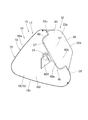
以下、本発明の一実施形態を図面に基づいて説明する。実施形態の助手席用エアバッグ装置Mは、図1,2に示すように、車両Vにおける助手席PSの前方において、インストルメントパネル(以下「インパネ」と省略する)1の上面2の内部に配置されるトップマウントタイプとされている。なお、実施形態において、前後・上下・左右の方向は、特に断らない限り、車両Vの前後・上下・左右の方向と一致するものである。 Hereinafter, an embodiment of the present invention will be described with reference to the drawings. As shown in FIGS. 1 and 2, the passenger seat airbag device M of the embodiment is located inside the upper surface 2 of the instrument panel (hereinafter abbreviated as “instrument panel”) 1 in front of the passenger seat PS in the vehicle V. It is said to be a top mount type to be placed. In the embodiment, the front-rear, up-down, and left-right directions coincide with the front-back, up-down, and left-right directions of the vehicle V unless otherwise specified.

実施形態の助手席用エアバッグ装置Mは、図1に示すように、折り畳まれたエアバッグ15と、エアバッグ15に膨張用ガスを供給するインフレーター8と、エアバッグ15及びインフレーター8を収納保持する収納部位としてのケース12と、エアバッグ15及びインフレーター8をケース12に取り付けるためのリテーナ9と、折り畳まれたエアバッグ15の上方を覆うエアバッグカバー6と、を備えて構成されている。 As shown in FIG. 1, the passenger seat airbag device M of the embodiment stores and holds a folded airbag 15, an inflator 8 that supplies an expansion gas to the airbag 15, and the airbag 15 and an inflator 8. It is configured to include a case 12 as a storage portion, a retainer 9 for attaching the airbag 15 and the inflator 8 to the case 12, and an airbag cover 6 that covers the upper part of the folded airbag 15.

エアバッグカバー6は、合成樹脂製のインパネ1と一体的に形成されて、エアバッグ15の展開膨張時に、前後二枚の扉部6a,6bを、エアバッグ15に押されて開くように、構成されている。また、エアバッグカバー6における扉部6a,6bの周囲には、ケース12に連結される連結壁部6cが、形成されている。 The airbag cover 6 is integrally formed with the instrument panel 1 made of synthetic resin, and when the airbag 15 is expanded and expanded, the two front and rear door portions 6a and 6b are pushed by the airbag 15 to open. It is configured. Further, a connecting wall portion 6c connected to the case 12 is formed around the door portions 6a and 6b of the airbag cover 6.

インフレーター8は、図1に示すように、複数のガス吐出口8bを有した略円柱状の本体部8aと、インフレーター8をケース12に取り付けるためのフランジ部8cと、を備えて構成されている。インフレーター8は、実施形態の場合、車両Vの前面衝突と、斜め衝突と、オフセット衝突と、の際に、作動するように構成されている。 As shown in FIG. 1, the inflator 8 is configured to include a substantially columnar main body portion 8a having a plurality of gas discharge ports 8b, and a flange portion 8c for attaching the inflator 8 to the case 12. .. In the case of the embodiment, the inflator 8 is configured to operate in the case of a frontal collision, an oblique collision, and an offset collision of the vehicle V.

収納部位としてのケース12は、上端側に長方形状の開口を有した板金製の略直方体形状に形成され、図1に示すように、インフレーター8を下方から挿入させて取り付ける略長方形状の底壁部12aと、底壁部12aの外周縁から上方に延びてエアバッグカバー6の連結壁部6cを係止する周壁部12bと、を備えて構成されている。実施形態の場合、エアバッグ15とインフレーター8とは、エアバッグ15内に配置させたリテーナ9の各ボルト9aを取付手段として、エアバッグ15におけるガス流入口21の周縁、ケース12の底壁部12a、及び、インフレーター8のフランジ部8cを、貫通させて、ナット10止めすることにより、ケース12の底壁部12aに連結される構成である。具体的には、ケース12の底壁部12aは、左右方向側を幅広として構成されるもので、左右方向の略中央となる位置に、インフレーター8を取り付ける構成とされている。また、ケース12の底壁部12aには、車両Vのボディ側に連結される図示しないブラケットが、配設されている。 The case 12 as a storage portion is formed in a substantially rectangular parallelepiped shape made of sheet metal having a rectangular opening on the upper end side, and as shown in FIG. 1, a substantially rectangular bottom wall to which the inflator 8 is inserted and attached from below. A peripheral wall portion 12b that extends upward from the outer peripheral edge of the bottom wall portion 12a and locks the connecting wall portion 6c of the airbag cover 6 is provided. In the case of the embodiment, the airbag 15 and the inflator 8 are attached to the peripheral edge of the gas inlet 21 in the airbag 15 and the bottom wall portion of the case 12 by using the bolts 9a of the retainer 9 arranged in the airbag 15 as attachment means. It is configured to be connected to the bottom wall portion 12a of the case 12 by penetrating the flange portion 8c of the inflator 8 and the inflator 8 and fixing the nut 10. Specifically, the bottom wall portion 12a of the case 12 is configured to be wide on the left-right direction side, and the inflator 8 is attached at a position substantially at the center in the left-right direction. Further, a bracket (not shown) connected to the body side of the vehicle V is arranged on the bottom wall portion 12a of the case 12.

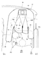
エアバッグ15は、図3〜7に示すように、内部に膨張用ガスを流入させて膨張するバッグ本体16と、バッグ本体16内に配置されてバッグ本体16の膨張完了形状を規制するテザー55,60L,60Rと、を備える構成とされている。 As shown in FIGS. 3 to 7, the airbag 15 includes a bag body 16 that expands by inflowing an expansion gas into the bag body 16 and a tether 55 that is arranged inside the bag body 16 and regulates the expansion completion shape of the bag body 16. , 60L, 60R, and so on.

バッグ本体16は、可撓性を有したシート体から形成される袋状とされるもので、実施形態の場合、図3〜7に示すように、本体膨張部17と、膨張完了時の本体膨張部17の後面側から後方に突出するように配置される2つの左側突出膨張部29,右側突出膨張部32と、を備えている。 The bag body 16 has a bag shape formed from a flexible sheet body, and in the case of the embodiment, as shown in FIGS. 3 to 7, the body expansion portion 17 and the body when expansion is completed. It includes two left-side protruding expansion portions 29 and right-side protruding expansion portions 32 that are arranged so as to project rearward from the rear surface side of the expansion portion 17.

本体膨張部17は、図1の二点鎖線に示すように、膨張完了時に、インパネ1の上面2とインパネ1上方のウィンドシールド4との間を塞ぐように配置可能な構成とされている。具体的には、本体膨張部17は、図3に示すように、膨張完了時の形状を、軸方向を左右方向に略沿わせた略三角柱状とされるもので、膨張完了時の前端側に、ケース12に取り付けられる取付部20を、備える構成とされている(図3,4,7参照)。すなわち、実施形態のエアバッグ15では、本体膨張部17は、膨張完了時の前端17a側をケース12に取り付けられて、膨張完了時に、図10に示すように、運転席DS側となる左側の領域を、若干、運転席DS側に張り出させるように、配置される構成である。この本体膨張部17は、膨張完了時に乗員MP側である後面側に配置される後側壁部26と、後側壁部26の周縁から前方に延びるとともに前端側にかけて上下の幅寸法を小さくするように収束される先細り形状の周壁部18と、を備えている。 As shown by the alternate long and short dash line in FIG. 1, the main body expansion portion 17 has a configuration that can be arranged so as to close between the upper surface 2 of the instrument panel 1 and the windshield 4 above the instrument panel 1 when the expansion is completed. Specifically, as shown in FIG. 3, the main body expansion portion 17 has a substantially triangular columnar shape in which the axial direction is substantially along the left-right direction when the expansion is completed, and the front end side when the expansion is completed. In addition, a mounting portion 20 to be mounted on the case 12 is provided (see FIGS. 3, 4, and 7). That is, in the airbag 15 of the embodiment, the main body expanding portion 17 is attached to the case 12 on the front end 17a side when the expansion is completed, and when the expansion is completed, the left side becomes the driver's seat DS side as shown in FIG. The area is arranged so as to slightly project to the driver's seat DS side. The main body expansion portion 17 extends forward from the peripheral edge of the rear side wall portion 26, which is arranged on the rear surface side on the occupant MP side when the expansion is completed, and reduces the vertical width dimension toward the front end side. It includes a tapered peripheral wall portion 18 that is converged.

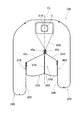
周壁部18は、エアバッグ15の膨張完了時に、主にインパネ1の上面2とインパネ1上方のウィンドシールド4との間を塞ぐように配置される部位であり、上下方向側で対向して配置される上壁部18a,下壁部18bと、左右方向側で対向して配置される左壁部18c,右壁部18dと、を備えている。実施形態のエアバッグ15では、周壁部18における膨張完了時の前端側の部位が、エアバッグ15をケース12に取り付けるための取付部20とされている。実施形態の場合、取付部20は、膨張完了時の左右方向側の幅寸法を、ケース12の左右方向側の幅寸法より大きく設定されている。この取付部20における膨張完了時の下面側(下壁部18b側)には、内部に膨張用ガスを流入可能に略円形に開口して形成されるガス流入口21と、ガス流入口21の周縁においてリテーナ9のボルト9aを挿通させるための複数(実施形態の場合、4個)の取付孔22と、が、形成されて、ガス流入口21の周縁をケース12の底壁部12aに取り付けられる構成である。ガス流入口21は、実施形態の場合、取付部20の左右の中央から若干右方にずれた位置に、配置されるもので、実施形態では、エアバッグ15は、このガス流入口21の中心を、取付中心C(図7参照)とし、この取付中心Cを助手席PSの左右方向の中心と略一致させるようにして、ケース12に取り付けられ、車両Vに搭載されている(図10参照)。また、周壁部18における左壁部18cと右壁部18dとには、内部に流入した余剰の膨張用ガスを排気させるためのベントホール24,24が、形成されている。 The peripheral wall portion 18 is a portion that is mainly arranged so as to close between the upper surface 2 of the instrument panel 1 and the windshield 4 above the instrument panel 1 when the expansion of the airbag 15 is completed, and is arranged so as to face each other in the vertical direction. The upper wall portion 18a and the lower wall portion 18b are provided, and the left wall portion 18c and the right wall portion 18d are arranged so as to face each other on the left-right direction side. In the airbag 15 of the embodiment, the portion of the peripheral wall portion 18 on the front end side when the expansion is completed is the attachment portion 20 for attaching the airbag 15 to the case 12. In the case of the embodiment, the mounting portion 20 is set so that the width dimension on the left-right direction side when the expansion is completed is larger than the width dimension on the left-right direction side of the case 12. On the lower surface side (lower wall portion 18b side) of the mounting portion 20 when expansion is completed, a gas inflow port 21 formed by opening a substantially circular opening so that expansion gas can flow into the inside, and a gas inflow port 21 A plurality of (four in the case of the embodiment) mounting holes 22 for inserting the bolts 9a of the retainer 9 at the peripheral edge are formed, and the peripheral edge of the gas inflow port 21 is attached to the bottom wall portion 12a of the case 12. It is a configuration that can be used. In the case of the embodiment, the gas inflow port 21 is arranged at a position slightly shifted to the right from the center of the left and right of the mounting portion 20, and in the embodiment, the airbag 15 is the center of the gas inflow port 21. Is the mounting center C (see FIG. 7), and the mounting center C is mounted on the case 12 and mounted on the vehicle V so as to substantially coincide with the center of the passenger seat PS in the left-right direction (see FIG. 10). ). Further, vent holes 24, 24 for exhausting excess expansion gas that has flowed into the inside are formed in the left wall portion 18c and the right wall portion 18d of the peripheral wall portion 18.

後側壁部26は、エアバッグ15の膨張完了時に、乗員MP側となる後面側において、上下方向に略沿うように配置されている。実施形態の場合、後側壁部26は、図2の二点鎖線及び図4に示すように、上下の中央を後方に位置させるように、上下方向に沿って湾曲されつつ、下端側を後方にずらすように上下方向に対して僅かに傾斜して、配置されている。また、この後側壁部26は、エアバッグ15の膨張完了時の前後方向に沿った横断面において、左右方向に略沿うように、配置されている(図7参照)。 The rear side wall portion 26 is arranged so as to substantially follow the vertical direction on the rear surface side, which is the occupant MP side, when the expansion of the airbag 15 is completed. In the case of the embodiment, the rear side wall portion 26 is curved along the vertical direction so that the upper and lower centers are located rearward as shown by the alternate long and short dash line in FIG. 2 and the lower end side is rearward. It is arranged so as to be slightly inclined with respect to the vertical direction so as to be offset. Further, the rear side wall portion 26 is arranged so as to substantially follow the left-right direction in the cross section along the front-rear direction when the expansion of the airbag 15 is completed (see FIG. 7).

そして、実施形態の場合、本体膨張部17は、膨張完了時の左右方向側の幅寸法を、前端側の取付部20から、後面側(後側壁部26)側にかけて略一定として、構成され、左壁部18cと右壁部18dとは、本体膨張部17の膨張完了時に、前後方向に略沿うようにして、配置されることとなる(図7参照)。そして、実施形態のエアバッグ15は、上述したごとく、取付部20の左右の中央よりも右方にずれた位置に配置されるガス流入口21をの中心を、取付中心C(図7参照)とし、この取付中心Cを助手席PSの左右方向の中心と略一致させるようにして、ケース12に取り付けられ、車両Vに搭載される構成であることから、車両搭載時における膨張完了状態において、本体膨張部17は、取付中心Cを通る前後方向に沿った取付中心線CLよりも左側(運転席DS側)に配置される領域を、右側(運転席DSから離隔した車外側)に配置される領域よりも、左右方向側の幅寸法を大きく(左右の外方への突出量を大きく)して、構成されることとなる(図10参照)。また、本体膨張部17の後側壁部26における左端側と右端側とには、エアバッグ15の膨張完了時に、後側壁部より後方に突出するように膨張する左側突出膨張部29(運転席側突出膨張部),右側突出膨張部32(離隔側突出膨張部)が、配置されている。 In the case of the embodiment, the main body expanding portion 17 is configured such that the width dimension on the left-right direction side when the expansion is completed is substantially constant from the mounting portion 20 on the front end side to the rear surface side (rear side wall portion 26) side. The left wall portion 18c and the right wall portion 18d are arranged so as to substantially follow the front-rear direction when the expansion of the main body expansion portion 17 is completed (see FIG. 7). Then, as described above, the airbag 15 of the embodiment has the mounting center C (see FIG. 7) centered on the gas inflow port 21 arranged at a position shifted to the right from the left and right centers of the mounting portion 20. Therefore, since the mounting center C is mounted on the case 12 and mounted on the vehicle V so as to substantially coincide with the center of the passenger seat PS in the left-right direction, the expansion is completed when the vehicle is mounted. The main body expansion portion 17 is arranged on the right side (outside the vehicle away from the driver's seat DS) in a region arranged on the left side (driver's seat DS side) of the mounting center line CL along the front-rear direction passing through the mounting center C. The width dimension on the left-right direction side is larger than that of the region (the amount of protrusion to the left and right outwards is larger) to be configured (see FIG. 10). Further, on the left end side and the right end side of the rear side wall portion 26 of the main body expansion portion 17, when the expansion of the airbag 15 is completed, the left end protrusion expansion portion 29 (driver's seat side) that expands so as to project rearward from the rear side wall portion. The protruding expansion portion) and the right protruding expansion portion 32 (separate side protruding expansion portion) are arranged.

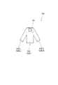
運転席側突出膨張部としての左側突出膨張部29は、後側壁部26において、運転席DS側となる左端側の部位に形成されるもので、エアバッグ15の膨張完了時に、助手席PSに着座した乗員MPの左斜め前方となる位置に、配置されることとなる(図10参照)。この左側突出膨張部29は、膨張完了時の前端29c側で本体膨張部17と連通されて、この前端29c側の連通部30を経て、本体膨張部17から内部に膨張用ガスを流入させる構成であり(図10参照)、膨張完了時の外形形状を、厚さ方向を左右方向に沿わせるように配置される略板状として、左右方向側から見て略台形状とされている。具体的には、左側突出膨張部29は、左右方向側から見た膨張完了形状を、本体膨張部17側となる前端29c側を幅広として、後端29d側にかけて狭幅とするような台形状とされている(図3,5,7参照)。この左側突出膨張部29は、膨張完了時に、左右方向側で対向するように配置される左壁部29aと右壁部29bとを備える構成とされており、左壁部29aは、本体膨張部17における周壁部18の左壁部18cから連なるように、構成されている(図7参照)。この左側突出膨張部29は、エアバッグ15の膨張完了時における前後方向に沿った横断面において、車両搭載時に、ケース12よりも左方となる位置に配置される構成である(図10参照)。 The left-side protruding expansion portion 29 as the driver-seat-side protruding expansion portion is formed on the rear side wall portion 26 at the left end side portion on the driver-seat DS side, and is formed on the passenger seat PS when the expansion of the airbag 15 is completed. It will be placed at a position diagonally forward to the left of the seated occupant MP (see FIG. 10). The left-side protruding expansion portion 29 is communicated with the main body expansion portion 17 on the front end 29c side when expansion is completed, and the expansion gas flows into the inside from the main body expansion portion 17 through the communication portion 30 on the front end 29c side. (See FIG. 10), the outer shape at the time of completion of expansion is a substantially plate shape arranged so as to be arranged along the left-right direction in the thickness direction, and is substantially trapezoidal when viewed from the left-right direction side. Specifically, the left-side protruding expansion portion 29 has a trapezoidal shape such that the expansion completion shape seen from the left-right direction side is wide on the front end 29c side, which is the main body expansion portion 17, and narrows toward the rear end 29d side. (See Figures 3, 5 and 7). The left-side protruding expansion portion 29 is configured to include a left wall portion 29a and a right wall portion 29b that are arranged so as to face each other in the left-right direction when the expansion is completed, and the left wall portion 29a is a main body expansion portion. It is configured so as to be continuous from the left wall portion 18c of the peripheral wall portion 18 in No. 17 (see FIG. 7). The left-side protruding expansion portion 29 is configured to be arranged at a position to the left of the case 12 when mounted on a vehicle in a cross section along the front-rear direction when the expansion of the airbag 15 is completed (see FIG. 10). ..

離隔側突出膨張部としての右側突出膨張部32は、後側壁部26において、運転席DSから離れた側となる右端側の部位に形成されるもので、エアバッグ15の膨張完了時に、助手席PSに着座した乗員MPの右斜め前方となる位置に、配置されることとなる(図10参照)。この右側突出膨張部32も、左側突出膨張部29と同様に、膨張完了時の前端32c側で本体膨張部17と連通されて、この前端32c側の連通部33を経て、本体膨張部17から内部に膨張用ガスを流入させる構成である(図7参照)。また、右側突出膨張部32も、膨張完了時の外形形状を、厚さ方向を左右方向に沿わせるように配置される略板状として、左右方向側から見て略台形状とされている(図3,6,7参照)。具体的には、右側突出膨張部32は、左右方向側から見た膨張完了形状を、本体膨張部17側となる前端32c側を幅広として、後端32d側にかけて狭幅とするような台形状とされている。この右側突出膨張部32は、膨張完了時に、左右方向側で対向するように配置される左壁部32aと右壁部32bとを備える構成とされており、右壁部32bは、本体膨張部17における周壁部18の右壁部18dから連なるように、構成されている(図10参照)。この右側突出膨張部32は、エアバッグ15の膨張完了時における前後方向に沿った横断面において、車両搭載時に、ケース12よりも右方となる位置に配置される構成である(図10参照)。また、右側突出膨張部32は、車両搭載時におけるエアバッグ15の膨張完了時において乗員MPの頭部MHを受け止めた際に、助手席PSの側方の窓Wを覆うように膨張している後述する頭部保護用のエアバッグ92と接触可能に、配置されることとなり、具体的には、実施形態の場合、右側突出膨張部32は、エアバッグ92と当接させるようにして、配置されることとなる(図10参照)。 The right-side protruding expansion portion 32 as the separation-side protruding expansion portion is formed on the rear side wall portion 26 at the right end side portion on the side away from the driver's seat DS, and is formed in the passenger seat when the expansion of the airbag 15 is completed. It will be placed at a position diagonally forward to the right of the occupant MP seated on the PS (see FIG. 10). Like the left-side protruding expansion portion 29, the right-side protruding expansion portion 32 is also communicated with the main body expansion portion 17 on the front end 32c side when expansion is completed, passes through the communication portion 33 on the front end 32c side, and is transmitted from the main body expansion portion 17. The configuration is such that an expansion gas flows into the inside (see FIG. 7). Further, the right-side protruding expansion portion 32 also has a substantially trapezoidal shape when viewed from the left-right direction side, with the outer shape at the completion of expansion being a substantially plate shape arranged so as to be arranged along the left-right direction in the thickness direction ( See Figures 3, 6 and 7). Specifically, the right-side protruding expansion portion 32 has a trapezoidal shape such that the expansion completion shape seen from the left-right direction side is wide on the front end 32c side, which is the main body expansion portion 17, and narrows toward the rear end 32d side. It is said that. The right-side protruding expansion portion 32 is configured to include a left wall portion 32a and a right wall portion 32b that are arranged so as to face each other on the left-right direction side when expansion is completed, and the right wall portion 32b is a main body expansion portion. It is configured so as to be continuous from the right wall portion 18d of the peripheral wall portion 18 in No. 17 (see FIG. 10). The right-side protruding expansion portion 32 is arranged at a position to the right of the case 12 when mounted on a vehicle in a cross section along the front-rear direction when the expansion of the airbag 15 is completed (see FIG. 10). .. Further, the right-side protruding expansion portion 32 is expanded so as to cover the side window W of the passenger seat PS when the head MH of the occupant MP is received when the expansion of the airbag 15 is completed when the airbag 15 is mounted on the vehicle. It will be arranged so that it can come into contact with the airbag 92 for head protection, which will be described later. Specifically, in the case of the embodiment, the right protruding expansion portion 32 is arranged so as to be in contact with the airbag 92. Will be done (see FIG. 10).

左側突出膨張部29と右側突出膨張部32とは、実施形態の場合、後側壁部26からの突出量を異ならせる以外は、外形寸法を略同一に設定されている。詳細に説明すれば、左側突出膨張部29と右側突出膨張部32とは、エアバッグ15の膨張完了時において、前端29c,32c側の部位の上下方向側の幅寸法L1を、本体膨張部17における後側壁部26の部位の上下方向側の幅寸法L2の2/3程度に設定され(図5参照)、左右方向側の幅寸法L3を、本体膨張部17の後端側の部位の左右方向側の幅寸法L4の1/4程度に、設定されている(図7参照)。さらに、左側突出膨張部29は、後側壁部26からの突出量(前後方向側の幅寸法L5)を、膨張完了時の本体膨張部17の前後方向側の幅寸法L6の1/4程度に設定されている(図7参照)。左側突出膨張部29の外形寸法は、エアバッグ15の膨張完了時において、右壁部29b(後述する左側斜突用拘束面38)に、左斜め前方に向かって移動する乗員MPの頭部MHを接触させた際に、この乗員MPの頭部MHを、的確に受け止め、かつ、右壁部29b(左側斜突用拘束面38)によって、乗員MPの頭部MHを、後述する左側拘束用凹部41に向かって、円滑に案内可能な寸法に、設定されている。また、実施形態では、膨張完了時に運転席DSから離れた側である右側に配置される右側突出膨張部32(離隔側突出膨張部)は、膨張完了時に運転席DS側に配置される左側突出膨張部29(運転席側突出膨張部)よりも、膨張完了時の本体膨張部17(後側壁部26)からの突出量を小さく設定されている。具体的には、右側突出膨張部32は、膨張完了時における後側壁部26からの突出量(前後方向側の幅寸法L7)を、左側突出膨張部29の後側壁部26からの突出量(前後方向側の幅寸法L5)の3/5程度に、設定されている(図7参照)。 In the case of the embodiment, the left-side protruding expansion portion 29 and the right-side protruding expansion portion 32 are set to have substantially the same external dimensions except that the amount of protrusion from the rear side wall portion 26 is different. More specifically, the left-side protruding expansion portion 29 and the right-side protruding expansion portion 32 have the width dimension L1 on the vertical direction of the front end 29c and 32c side portions when the expansion of the airbag 15 is completed, and the main body expansion portion 17 The width dimension L3 on the left-right direction side is set to about 2/3 of the width dimension L2 on the vertical side of the portion of the rear side wall portion 26 in the above (see FIG. 5), and the width dimension L3 on the left-right direction side is set to the left and right of the portion on the rear end side of the main body expansion portion 17. It is set to about 1/4 of the width dimension L4 on the direction side (see FIG. 7). Further, the left-side protruding expansion portion 29 reduces the amount of protrusion from the rear side wall portion 26 (width dimension L5 on the front-rear direction side) to about 1/4 of the width dimension L6 on the front-rear direction side of the main body expansion portion 17 when expansion is completed. It is set (see FIG. 7). The external dimensions of the left protruding expansion portion 29 are such that when the expansion of the airbag 15 is completed, the head MH of the occupant MP that moves diagonally forward to the left on the right wall portion 29b (restraint surface 38 for left oblique collision described later). The head MH of the occupant MP is accurately received when they are brought into contact with each other, and the head MH of the occupant MP is used for the left restraint described later by the right wall portion 29b (restraint surface 38 for left oblique collision). The dimensions are set so that they can be smoothly guided toward the recess 41. Further, in the embodiment, the right-side protruding expansion portion 32 (separate-side protruding expansion portion) arranged on the right side, which is the side away from the driver's seat DS when the expansion is completed, is arranged on the driver's seat DS side when the expansion is completed. The amount of protrusion from the main body expansion portion 17 (rear side wall portion 26) at the completion of expansion is set to be smaller than that of the expansion portion 29 (driver's seat side protruding expansion portion). Specifically, the right-side protruding expansion portion 32 determines the amount of protrusion from the rear side wall portion 26 (width dimension L7 on the front-rear direction side) when expansion is completed, and the amount of protrusion from the rear side wall portion 26 of the left-side protruding expansion portion 29 ( It is set to about 3/5 of the width dimension L5) on the front-rear direction side (see FIG. 7).

すなわち、実施形態のエアバッグ15(バッグ本体16)では、本体膨張部17が、取付中心Cを通る前後方向に沿った取付中心線CLよりも左側(運転席DS側)に配置される領域を、右側(運転席DSから離隔した車外側)に配置される領域よりも、左右方向側の幅寸法を大きく(左右方向側への突出量を大きく)して、構成され、また、右側突出膨張部32が、膨張完了時の本体膨張部17からの突出量を、左側突出膨張部29より小さく設定される構成であり、エアバッグ15は、取付中心C(中心線CL)を中心として左右方向側で略二分した際における運転席DSから離れた側に配置される離隔側領域としての右側領域15bを、運転席DS側に配置される運転席側領域としての左側領域15aよりも、容積を小さく設定される構成である。具体的には、エアバッグ15において、膨張完了時の右側領域15bの左右方向側の幅寸法L13は、左側領域15aの左右方向側の幅寸法L12の7/8程度に設定され(図7参照)、左側領域15aと右側領域15bとの容積比は、8:6〜8:7程度(好ましくは8:7)に設定されている。 That is, in the airbag 15 (bag body 16) of the embodiment, the area where the body expansion portion 17 is arranged on the left side (driver's seat DS side) of the mounting center line CL along the front-rear direction passing through the mounting center C is defined. , The width dimension on the left-right direction side is larger than the area arranged on the right side (outside the vehicle away from the driver's seat DS) (the amount of protrusion on the left-right direction side is larger). The portion 32 has a configuration in which the amount of protrusion from the main body expanding portion 17 at the completion of expansion is set to be smaller than that of the left protruding expanding portion 29, and the airbag 15 is located in the left-right direction about the mounting center C (center line CL). The volume of the right side region 15b as the separation side region arranged on the side away from the driver's seat DS when roughly bisected on the side is larger than the left side region 15a as the driver's seat side region arranged on the driver's seat DS side. The configuration is set small. Specifically, in the airbag 15, the width dimension L13 on the left-right side of the right side region 15b when expansion is completed is set to about 7/8 of the width dimension L12 on the left-right side of the left side region 15a (see FIG. 7). ), The volume ratio between the left side region 15a and the right side region 15b is set to about 8: 6 to 8: 7 (preferably 8: 7).

そして、実施形態のエアバッグ15では、左側突出膨張部29と、右側突出膨張部32と、本体膨張部17における後側壁部26と、が、エアバッグ15の膨張完了時に乗員MPを保護可能な乗員保護部35を構成している。乗員保護部35は、車両Vの前突時に前進移動する乗員MPの頭部MHを保護可能な前突用拘束面36と、車両Vの斜め衝突時若しくはオフセット衝突時に斜め前方に向かって移動する乗員MPの頭部MHを保護可能な2つの左側斜突用拘束面38,右側斜突用拘束面39と、を備える構成とされており、また、前突用拘束面36と各左側斜突用拘束面38,右側斜突用拘束面39との間には、乗員MPの頭部MHを進入させて拘束させるための左側拘束用凹部41,右側拘束用凹部46が、それぞれ、形成されている。 Then, in the airbag 15 of the embodiment, the left-side protruding expansion portion 29, the right-side protruding expansion portion 32, and the rear side wall portion 26 in the main body expansion portion 17 can protect the occupant MP when the expansion of the airbag 15 is completed. It constitutes the occupant protection unit 35. The occupant protection unit 35 moves diagonally forward when the vehicle V has a diagonal collision or an offset collision with a front collision restraint surface 36 which can protect the head MH of the occupant MP which moves forward when the vehicle V collides forward. It is configured to include two restraint surfaces for left oblique collision 38 and a restraint surface 39 for right oblique impact that can protect the head MH of the occupant MP, and also has a restraint surface 36 for front collision and each left oblique collision. A left side restraint recess 41 and a right side restraint recess 46 for allowing the head MH of the occupant MP to enter and restrain the occupant MP are formed between the restraint surface 38 and the right side slanting restraint surface 39, respectively. There is.

実施形態の場合、前突用拘束面36は、後側壁部26の上側の領域から構成されるもので、膨張完了時のエアバッグ15において、左側突出膨張部29と右側突出膨張部32との間に配置される領域から、構成されている。この前突用拘束面36は、左右方向側の幅寸法を、前突時に前進移動する乗員MPの頭部MHを支障なく保護可能に、構成されている。また、実施形態では、エアバッグ15は、内部に、後述する前後テザー55を配設させる構成とされており、前突用拘束面36は、エアバッグ15の膨張完了時に、前後方向に略沿った横断面において、前後テザー55を連結させている取付中心線CL上となる位置を、前方側に向かって僅かに凹ませるように、構成されている(図7参照)。また、実施形態のエアバッグ15では、上述したように、本体膨張部17は、取付中心Cを通る前後方向に沿った取付中心線CLよりも左側(運転席DS側)に配置される領域を、右側(運転席DSから離隔した車外側)に配置される領域よりも、左右方向側の幅寸法を大きく(左右方向側への突出量を大きく)して、構成されており、換言すれば、前突用拘束面36は、前後テザー55より運転席DS側(左側)に配置される運転席側部位としての左側部位36aを、前後テザー55よりも運転席DSから離れた離隔側(右側)に配置される離隔側部位としての右側部位36bよりも、膨張完了時の左右方向側の長さ寸法を大きくするように、構成されている。具体的には、実施形態の場合、右側部位36bの左右方向側の幅寸法(長さ寸法)L8は、左側部位36aの左右方向側の幅寸法L9の3/4程度に設定されている(図7参照)。この右側部位36bの左右方向側の幅寸法は、エアバッグ15の膨張完了時に、右側突出膨張部32を、窓Wを覆うように膨張している頭部保護用のエアバッグ92との大きな干渉を抑制して、円滑に配置可能な寸法に、設定されている。 In the case of the embodiment, the front collision restraint surface 36 is composed of the upper region of the rear side wall portion 26, and in the airbag 15 when the expansion is completed, the left protruding expansion portion 29 and the right protruding expansion portion 32 It is composed of areas arranged between them. The front collision restraint surface 36 is configured so that the width dimension on the left-right direction side can protect the head MH of the occupant MP that moves forward at the time of front collision without hindrance. Further, in the embodiment, the airbag 15 is configured to dispose the front and rear tethers 55 described later inside, and the front collision restraint surface 36 substantially follows the front-rear direction when the expansion of the airbag 15 is completed. In the cross section, the position on the mounting center line CL connecting the front and rear tethers 55 is configured to be slightly recessed toward the front side (see FIG. 7). Further, in the airbag 15 of the embodiment, as described above, the main body expansion portion 17 has a region arranged on the left side (driver's seat DS side) of the mounting center line CL along the front-rear direction passing through the mounting center C. , The width dimension on the left-right direction side is larger than the area arranged on the right side (outside the vehicle away from the driver's seat DS) (the amount of protrusion to the left-right direction side is larger), in other words. The front collision restraint surface 36 has a left side portion 36a as a driver's seat side portion arranged on the driver's seat DS side (left side) from the front and rear tethers 55, and a separated side (right side) away from the driver's seat DS than the front and rear tether 55. ) Is configured to have a larger length dimension on the left-right direction side when expansion is completed than the right-side portion 36b as the separation side portion. Specifically, in the case of the embodiment, the width dimension (length dimension) L8 on the left-right side of the right side portion 36b is set to about 3/4 of the width dimension L9 on the left-right direction side of the left side portion 36a (). (See FIG. 7). The width dimension of the right side portion 36b on the left-right side greatly interferes with the head protection airbag 92 inflating the right protruding inflatable portion 32 so as to cover the window W when the expansion of the airbag 15 is completed. The size is set so that it can be placed smoothly.

運転席DS側となる左側に配置される左側斜突用拘束面38は、左側突出膨張部29の右壁部29bから構成されている。運転席DSから離れた側となる右側に配置される右側斜突用拘束面39は、右側突出膨張部32の左壁部32aから構成されている。そして、実施形態では、上述したごとく、右側突出膨張部32は、エアバッグ15の膨張完了時における後側壁部26からの後方への突出量を、左側突出膨張部29よりも小さく設定されており、換言すれば、右側斜突用拘束面39は、前後方向側の長さ寸法を、左側斜突用拘束面38よりも小さく設定されている。そして、左側斜突用拘束面38と右側斜突用拘束面39とは、それぞれ、エアバッグ15の膨張完了時に、前後方向に略沿うように、配置される(図7参照)。また、実施形態のエアバッグ15において、後側壁部26における下側の領域は、前突時や斜突時、オフセット衝突時に前進移動する乗員MPが頭部MHを乗員保護部35に拘束された際に、主に、乗員MPの胸部を受け止めることとなる。 The left diagonal collision restraint surface 38 arranged on the left side on the driver's seat DS side is composed of the right wall portion 29b of the left protruding expansion portion 29. The right side oblique collision restraint surface 39 arranged on the right side away from the driver's seat DS is composed of the left wall portion 32a of the right side protruding expansion portion 32. Then, in the embodiment, as described above, the right-side protruding expansion portion 32 is set so that the amount of protrusion rearward from the rear side wall portion 26 when the expansion of the airbag 15 is completed is smaller than that of the left-side protruding expansion portion 29. In other words, the right side oblique collision restraint surface 39 is set to have a length dimension on the front-rear direction side smaller than that of the left side oblique collision restraint surface 38. The left side oblique collision restraint surface 38 and the right side oblique collision restraint surface 39 are arranged so as to substantially follow the front-rear direction when the expansion of the airbag 15 is completed (see FIG. 7). Further, in the airbag 15 of the embodiment, in the lower region of the rear side wall portion 26, the occupant MP that moves forward at the time of a front collision, an oblique collision, or an offset collision restrains the head MH by the occupant protection portion 35. At that time, it mainly receives the chest of the occupant MP.

前突用拘束面36と左側斜突用拘束面38との間に形成される左側拘束用凹部41は、左斜め前方に向かって移動する乗員MPの頭部MHを進入させて拘束するためのものであり、実施形態の場合、左側突出膨張部29の右側の領域と、本体膨張部17における後側壁部26と、の境界部位に、上下方向に略沿うようにして、形成されるとともに、図5,7に示すように、後端41b側を開口させて、ポケット状に前方に凹む構成とされている。すなわち、左側拘束用凹部41は、前突用拘束面36の左縁側に、形成されている。詳細には、左側拘束用凹部41は、左右方向側から見て、上下に幅広とした略長方形状の左側壁43と右側壁44との上縁相互、下縁相互、前縁相互を、それぞれ、結合(縫着)させることにより、後端41b側を開口させた略ポケット状に、構成されている(図5参照)。すなわち、左側拘束用凹部41は、前端41a側(凹みの先端側)にかけて、幅寸法を一定として、構成されている。 The left side restraint recess 41 formed between the front collision restraint surface 36 and the left side oblique collision restraint surface 38 is for entering and restraining the head MH of the occupant MP moving diagonally forward to the left. In the case of the embodiment, the region on the right side of the left protruding expansion portion 29 and the rear side wall portion 26 of the main body expansion portion 17 are formed so as to substantially follow the vertical direction. As shown in FIGS. 5 and 7, the rear end 41b side is opened and the rear end 41b side is recessed forward in a pocket shape. That is, the left restraint recess 41 is formed on the left edge side of the front collision restraint surface 36. Specifically, the left side restraint recess 41 has a substantially rectangular shape of the left side wall 43 and the right side wall 44, which are wide in the vertical direction when viewed from the left-right direction side. By joining (sewing), the rear end 41b side is opened in a substantially pocket shape (see FIG. 5). That is, the left side restraint recess 41 is configured with a constant width dimension toward the front end 41a side (tip side of the recess).

前突用拘束面36と右側斜突用拘束面39との間に形成される右側拘束用凹部46は、右斜め前方に向かって移動する乗員MPの頭部MHを進入させて拘束するためのものであり、実施形態の場合、右側突出膨張部32の左側の領域と、本体膨張部17における後側壁部26と、の境界部位に、上下方向に略沿うようにして、形成されるとともに、図6,7に示すように、後端46b側を開口させて、ポケット状に前方に凹む構成とされている。すなわち、右側拘束用凹部46は、前突用拘束面36の右縁側に、形成されている。詳細には、右側拘束用凹部46は、左右方向側から見て、上下に幅広とした略長方形状の左側壁48と右側壁49との上縁相互、下縁相互、前縁相互を、それぞれ、結合(縫着)させることにより、後端46b側を開口させた略ポケット状に、構成されている(図6参照)。すなわち、右側拘束用凹部46は、前端46a側(凹みの先端側)にかけて、幅寸法を一定として、構成されている。 The right side restraint recess 46 formed between the front collision restraint surface 36 and the right side oblique collision restraint surface 39 is for entering and restraining the head MH of the occupant MP moving diagonally forward to the right. In the case of the embodiment, the region on the left side of the right protruding expansion portion 32 and the rear side wall portion 26 in the main body expansion portion 17 are formed so as to substantially follow the vertical direction. As shown in FIGS. 6 and 7, the rear end 46b side is opened and the rear end 46b side is recessed forward in a pocket shape. That is, the right side restraint recess 46 is formed on the right edge side of the front collision restraint surface 36. Specifically, the right-side restraint recess 46 has a substantially rectangular left wall 48 and a right-side wall 49 that are wide in the vertical direction when viewed from the left-right direction side. By combining (sewing), the rear end 46b side is opened in a substantially pocket shape (see FIG. 6). That is, the right side restraint recess 46 is configured with a constant width dimension toward the front end 46a side (tip side of the recess).

実施形態の場合、左側拘束用凹部41と右側拘束用凹部46とは、外形形状を略同一として、構成されている。各左側拘束用凹部41,右側拘束用凹部46は、上下方向側の長さ寸法(開口42の開口幅寸法)を、乗員MPの頭部MHを円滑に進入させることが可能な寸法に、設定されている。具体的には、左側拘束用凹部41,右側拘束用凹部46は、上下方向側の長さ寸法L10(開口42の開口幅寸法)を、左側突出膨張部29,右側突出膨張部32の前端29c,32c側の部位の上下方向側の幅寸法L1よりも小さく設定されて、400mm程度に設定されている(図5参照)。また、左側拘束用凹部41,右側拘束用凹部46の前後方向側の幅寸法(深さ)L11は、乗員MPの頭部MHの前側の領域を進入可能な寸法に設定されており、具体的には、50〜100mm程度に設定されている(図5参照)。これらの左側拘束用凹部41,右側拘束用凹部46は、それぞれ、左側突出膨張部29,右側突出膨張部32と、上下の中央を略一致させるように、配置されている。 In the case of the embodiment, the left side restraint recess 41 and the right side restraint recess 46 are configured so that the outer shapes are substantially the same. Each of the left side restraint recess 41 and the right side restraint recess 46 is set to have a vertical length dimension (opening width dimension of the opening 42) so that the head MH of the occupant MP can smoothly enter. Has been done. Specifically, the left side restraint recess 41 and the right side restraint recess 46 have a length dimension L10 (opening width dimension of the opening 42) on the vertical direction, and the front end 29c of the left protrusion expansion portion 29 and the right protrusion expansion portion 32. , The width dimension L1 on the vertical side of the portion on the 32c side is set to be smaller than the width dimension L1 and is set to about 400 mm (see FIG. 5). Further, the width dimension (depth) L11 on the front-rear side of the left-side restraint recess 41 and the right-side restraint recess 46 is set to a dimension that allows entry into the region on the front side of the head MH of the occupant MP. Is set to about 50 to 100 mm (see FIG. 5). The left side restraint recess 41 and the right side restraint recess 46 are arranged so as to substantially coincide with the left side protrusion expansion portion 29 and the right side protrusion expansion portion 32, respectively.

また、実施形態のエアバッグ15では、左側拘束用凹部41と右側拘束用凹部46とは、それぞれ、凹みの先端(前端41a,46a)側を、バッグ本体16内に配置される凹部用テザー60L,60Rに連結されて、エアバッグ15の膨張完了時に、凹部用テザー60L,60Rによって、凹みの先端側(前端41a,46a側)を前方に牽引された状態で、配置されることとなる(図7参照)。実施形態の場合、左側拘束用凹部41は、エアバッグ15の膨張完了時に、左側壁43と右側壁44とを略全域にわたって接触させるように、後端41b側の開口42の口開きを抑制された状態で、左側突出膨張部29の右壁部29bから連なるように、前後方向に略沿って配置されることとなり、右側拘束用凹部46も、同様に、左側壁48と右側壁49とを略全域にわたって接触させるように、後端46b側の開口47の口開きを抑制された状態で、右側突出膨張部32の左壁部32aから連なるように、前後方向に略沿って配置されることとなる。 Further, in the airbag 15 of the embodiment, the left side restraint recess 41 and the right side restraint recess 46 each have a recess tether 60L in which the tip ends (front ends 41a, 46a) of the recess are arranged in the bag body 16. , 60R, and when the expansion of the airbag 15 is completed, the recess tethers 60L and 60R are arranged in a state where the tip side (front end 41a, 46a side) of the recess is pulled forward (the front end 41a, 46a side). (See FIG. 7). In the case of the embodiment, the left restraint recess 41 suppresses the opening of the opening 42 on the rear end 41b side so that the left wall 43 and the right wall 44 come into contact with each other over substantially the entire area when the expansion of the airbag 15 is completed. In this state, it is arranged substantially along the front-rear direction so as to be continuous from the right wall portion 29b of the left protruding expansion portion 29, and the right restraint recess 46 also similarly connects the left wall 48 and the right wall 49. It is arranged substantially along the front-rear direction so as to be continuous from the left wall portion 32a of the right protruding expansion portion 32 in a state where the opening of the opening 47 on the rear end 46b side is suppressed so as to make contact over substantially the entire area. It becomes.

バッグ本体16内には、図4〜7に示すように、テザー55,60L,60Rが、配置されている。具体的には、本体膨張部17の領域内に、前後テザー55と、凹部用テザー60L,60Rとが、配置されている。 As shown in FIGS. 4 to 7, tethers 55, 60L, and 60R are arranged in the bag body 16. Specifically, the front and rear tethers 55 and the recessed tethers 60L and 60R are arranged in the region of the main body expansion portion 17.

前後テザー55は、前突用拘束面36の左右の中央よりやや右方となる位置と、エアバッグ15(本体膨張部17)の前端17a側と、を連結するもので、図7に示すように、エアバッグ15の膨張完了時に、中心線CL上に位置するように配置されて、ガス流入口21の周縁から延びる前側部位56と、後側壁部26側から延びる後側部位57と、を連結させるようにして、構成されている(図4参照)。 The front-rear tether 55 connects a position slightly to the right of the left and right centers of the front collision restraint surface 36 and the front end 17a side of the airbag 15 (main body expansion portion 17), as shown in FIG. In addition, when the expansion of the airbag 15 is completed, the front side portion 56 extending from the peripheral edge of the gas inflow port 21 and the rear side portion 57 extending from the rear side wall portion 26 side are arranged so as to be located on the center line CL. It is configured so as to be connected (see FIG. 4).

前側部位56は、ガス流入口21の周縁から延びるように配置されるとともに、実施形態の場合、図8に示す前側部位用基材58を折って構成されるもので、左右対称形として、バッグ本体16の膨張完了時における外形形状を、前端側を左右方向に略沿わせ、後端側を上下方向に略沿わせるような略三角錐形状に近似した立体形状とされている。前側部位用基材58は、長手方向を前後方向側に沿わせて構成される帯状とされている。実施形態の場合、前側部位56は、図4,7に示すように、前端側の領域を、バッグ本体16への連結部56aとして、この連結部56aにガス流入口21及び取付孔22に対応する開口(図符号省略)を配置させて、ガス流入口21の周縁の部位で、本体膨張部17における取付部20の下面側の部位に縫着されている。そして、前側部位56において、ガス流入口21から後方に延びる領域が、本体部56bを構成し、この本体部56bの外形形状を、略三角錐形状に近似した立体形状としている(図4参照)。本体部56bは、後側部位57の前端57a側に縫着される後端56c側の部位の上下の幅寸法を、後側部位57における前端57a側の部位の上下の幅寸法と、略一致させるように構成されている。 The front portion 56 is arranged so as to extend from the peripheral edge of the gas inflow port 21, and in the case of the embodiment, the front portion base material 58 shown in FIG. 8 is folded to form a bag as a symmetrical shape. The outer shape of the main body 16 at the completion of expansion is a three-dimensional shape similar to a substantially triangular pyramid shape such that the front end side substantially follows the left-right direction and the rear end side substantially follows the vertical direction. The base material 58 for the front side portion has a strip shape formed along the front-rear direction side in the longitudinal direction. In the case of the embodiment, as shown in FIGS. 4 and 7, the front end portion 56 has a region on the front end side as a connecting portion 56a to the bag body 16 and corresponds to the gas inflow port 21 and the mounting hole 22 in the connecting portion 56a. An opening (not shown in the figure) is arranged and sewn to a portion on the lower surface side of the mounting portion 20 in the main body expansion portion 17 at a portion on the peripheral edge of the gas inflow port 21. Then, in the front side portion 56, the region extending rearward from the gas inflow port 21 constitutes the main body portion 56b, and the outer shape of the main body portion 56b is a three-dimensional shape that approximates a substantially triangular pyramid shape (see FIG. 4). .. The main body portion 56b substantially matches the vertical width dimension of the portion on the rear end 56c side sewn to the front end 57a side of the rear side portion 57 with the vertical width dimension of the portion on the front end 57a side of the rear side portion 57. It is configured to let you.

後側部位57は、シート状として、実施形態の場合、本体膨張部17における後側壁部26を構成する後左パネル79の右縁79d,後右パネル81の左縁81cから延びて、後左パネル79及び後右パネル81と一体的に構成される延設部79e,81eから、構成されている(図7,9参照)。換言すれば、後側部位57は、左右方向側で重ねられる二枚重ね状とされている。詳細には、実施形態の場合、後側部位57は、前側部位56に連結される前端57a側を狭幅として、後端57b側にかけて上下に拡開されるような略台形状として、構成されており、実施形態の場合、後側壁部26の上下の略中央となる位置に、連結されている。 In the case of the embodiment, the rear side portion 57 extends from the right edge 79d of the rear left panel 79 and the left edge 81c of the rear right panel 81 constituting the rear side wall portion 26 of the main body expansion portion 17, and is rear left. It is composed of extension portions 79e and 81e integrally formed with the panel 79 and the rear right panel 81 (see FIGS. 7 and 9). In other words, the rear side portion 57 has a double-layered shape in which the rear side portion 57 is stacked on the left-right direction side. Specifically, in the case of the embodiment, the rear side portion 57 is configured as a substantially trapezoidal shape such that the front end 57a side connected to the front end portion 56 is narrowed and the rear end 57b side is expanded vertically. In the case of the embodiment, the rear side wall portion 26 is connected at a position substantially at the center of the top and bottom.

この前後テザー55は、エアバッグ15の膨張完了時に、後側壁部26において取付中心Cを通る前後方向に沿った中心線CLと交差する部位(前面衝突時に乗員MPを保護するための保護中心)と、ガス流入口21の周縁部位と、の離隔距離を規制するもので、換言すれば、前突用拘束面36とエアバッグ15(本体膨張部17)の前端17a側とを連結する構成である。そして、この前後テザー55は、エアバッグ15の膨張初期における前突用拘束面36の過度の後方への突出や、膨張完了時の前突用拘束面36の後方移動を、抑制するために、配置されている。また、実施形態では、後側壁部26は、この前後テザー55に牽引されるようにして、エアバッグ15の膨張完了時に、中心線CL上となる位置を、上下の略全域にわたって、わずかに、車両前方側に向かって凹ませて、配設されることとなる(図7参照)。 When the expansion of the airbag 15 is completed, the front-rear tether 55 intersects the center line CL along the front-rear direction passing through the mounting center C in the rear side wall portion 26 (protection center for protecting the occupant MP in the event of a frontal collision). In other words, the front collision restraint surface 36 and the front end 17a side of the airbag 15 (main body expansion portion 17) are connected to each other to regulate the separation distance between the peripheral portion of the gas inlet 21 and the peripheral portion. is there. Then, the front-rear tether 55 suppresses the excessive rearward protrusion of the front collision restraint surface 36 at the initial stage of expansion of the airbag 15 and the rearward movement of the front collision restraint surface 36 at the completion of expansion. Have been placed. Further, in the embodiment, the rear side wall portion 26 is pulled by the front and rear tethers 55, and when the expansion of the airbag 15 is completed, the position on the center line CL is slightly set over substantially the entire upper and lower parts. It is arranged so as to be recessed toward the front side of the vehicle (see FIG. 7).

各凹部用テザー60L,60Rは、エアバッグ15の膨張完了時に、図7に示すように、それぞれ、左側拘束用凹部41,右側拘束用凹部46の凹みの先端(側(前端41a,46a側)と、エアバッグ15の前端17a側と、を、連結するように、配置されるもので、実施形態の場合、略左右対称形とされている。各凹部用テザー60L,60Rは、図8に示すテザー用基布62L,62Rから構成されるもので、各テザー用基布62L,62Rは、帯状の本体部64L,64Rと、本体部64L,64Rの前端64a側において左右方向の内方側に突出するように形成される連結部63L,63Rと、を備えている。そして、各凹部用テザー60L,60Rは、このテザー用基布62L,62Rの前端側の連結部63L,63Rを、相互に重ねるようにしてガス流入口21の周縁に結合(縫着)させ、ガス流入口21の左右両側からそれぞれ延びる本体部64L,64Rの後端64b側を、各左側拘束用凹部41,右側拘束用凹部46の前端41a,46a側に連結させることにより、エアバッグ15の膨張完了時に、後端64bを左右方向の外方側に向けるように、前後方向に対して、傾斜して配置される構成である。各凹部用テザー60L,60Rは、長さ寸法を、エアバッグ15の膨張完了時に、前後方向に略沿って配置される左側拘束用凹部41,右側拘束用凹部46を、それぞれ、前方に牽引可能に、設定されている。 When the expansion of the airbag 15 is completed, the recessed tethers 60L and 60R are provided with the tips of the recesses of the left restraint recess 41 and the right restraint recess 46 (sides (front ends 41a, 46a side), respectively) as shown in FIG. And the front end 17a side of the airbag 15 are arranged so as to be connected to each other, and in the case of the embodiment, the tethers 60L and 60R for the recesses are substantially symmetrical. It is composed of the tether base cloths 62L and 62R shown, and each tether base cloth 62L and 62R has a strip-shaped main body portions 64L and 64R and the front end 64a side of the main body portions 64L and 64R on the inner side in the left-right direction. The connecting portions 63L and 63R are formed so as to project from each other, and the recessed tethers 60L and 60R connect the connecting portions 63L and 63R on the front end side of the tether base cloths 62L and 62R. The rear ends 64b of the main bodies 64L and 64R extending from the left and right sides of the gas inlet 21 are connected (sewn) to the peripheral edge of the gas inlet 21 so as to overlap each other. By connecting to the front ends 41a and 46a of the restraint recess 46, when the expansion of the airbag 15 is completed, the rear end 64b is arranged so as to be inclined with respect to the front-rear direction so as to face the outward side in the left-right direction. Each of the recessed tethers 60L and 60R has a length dimension of a left restraint recess 41 and a right restraint recess 46 arranged substantially along the front-rear direction when the expansion of the airbag 15 is completed, respectively. , It is set to be towable forward.

バッグ本体16は、所定形状の基布の周縁相互を結合させて袋状に構成されるもので、実施形態の場合、図8,9に示すように、膨張完了時に前側に配置される前パネル70、膨張完了時に左側に配置される左パネル71、膨張完了時に右側に配置される右パネル75、膨張完了時に後側に配置される後左パネル79,後右パネル81、左側突出膨張部29の右壁部29bを構成する左側突出部用パネル84、及び、右側突出膨張部32の左壁部32aを構成する右側突出部用パネル86、の7枚の基布から構成されている。 The bag body 16 is formed in a bag shape by connecting the peripheral edges of a base cloth having a predetermined shape to each other, and in the case of the embodiment, as shown in FIGS. 8 and 9, a front panel arranged on the front side when expansion is completed. 70, left panel 71 arranged on the left side when expansion is completed, right panel 75 arranged on the right side when expansion is completed, rear left panel 79 arranged on the rear side when expansion is completed, rear right panel 81, left protruding expansion part 29 It is composed of seven base fabrics, a left protruding portion panel 84 forming the right wall portion 29b and a right protruding portion panel 86 forming the left wall portion 32a of the right protruding expanding portion 32.

前パネル70は、外形形状を、長手方向を前後方向に略沿わせた略帯状として構成されるもので、膨張完了時の本体膨張部17における上壁部18aから下壁部18bにかけての領域を、構成している。この前パネル70には、ガス流入口21と取付孔22とが、形成されるが、ガス流入口21は、中心を、前パネル70の幅方向の中央よりやや右方にずらすようにして、配置されている。 The front panel 70 is configured such that the outer shape is substantially strip-shaped with the longitudinal direction substantially along the front-rear direction, and the region from the upper wall portion 18a to the lower wall portion 18b in the main body expansion portion 17 at the completion of expansion is formed. , Consists. A gas inflow port 21 and a mounting hole 22 are formed in the front panel 70, and the center of the gas inflow port 21 is slightly shifted to the right from the center in the width direction of the front panel 70. Have been placed.

左パネル71は、膨張完了時の本体膨張部17における左壁部18cから、左側突出膨張部29の左壁部29aにかけての部位を、構成するもので、図9に示すように、本体膨張部17の左壁部18cの領域を構成する略三角形状の本体部72の後端側に、左側突出膨張部29の左壁部29aを構成する略台形状の突出部73を、連結させて構成されている。右パネル75は、膨張完了時の本体膨張部17における右壁部18dから、右側突出膨張部32の右壁部32bにかけての部位を構成するもので、図9に示すように、本体膨張部17の右壁部18dの領域を構成する略三角形状の本体部76の後端側に、右側突出膨張部32の右壁部32bを構成する略台形状の突出部77を、連結させて構成されている。右パネル75の本体部76は、外形形状を、左パネル71の本体部72と略同一とされている。右パネル75に形成される突出部77は、本体部76からの突出量を、左パネル71の突出部73における本体部72からの突出量より小さく設定されている。 The left panel 71 constitutes a portion from the left wall portion 18c of the main body expansion portion 17 when the expansion is completed to the left wall portion 29a of the left protruding expansion portion 29, and as shown in FIG. 9, the main body expansion portion A substantially trapezoidal protruding portion 73 forming the left wall portion 29a of the left protruding expanding portion 29 is connected to the rear end side of the substantially triangular main body portion 72 forming the region of the left wall portion 18c of 17. Has been done. The right panel 75 constitutes a portion from the right wall portion 18d of the main body expansion portion 17 at the completion of expansion to the right wall portion 32b of the right protruding expansion portion 32, and as shown in FIG. 9, the main body expansion portion 17 A substantially trapezoidal protruding portion 77 forming the right wall portion 32b of the right protruding expanding portion 32 is connected to the rear end side of the substantially triangular main body portion 76 forming the region of the right wall portion 18d. ing. The outer shape of the main body 76 of the right panel 75 is substantially the same as that of the main body 72 of the left panel 71. The protrusion 77 formed on the right panel 75 is set so that the amount of protrusion from the main body 76 is smaller than the amount of protrusion from the main body 72 of the protrusion 73 of the left panel 71.

後左パネル79,後右パネル81は、膨張完了時の本体膨張部17における後側壁部26の部位を、左右で分割するように構成されるもので、それぞれ、長手方向を上下方向に略沿わせた帯状として構成されている。実施形態の場合、後右パネル81は、幅寸法を、後左パネル79より若干小さく設定されている。後左パネル79の右縁79dと、後右パネル81の左縁81cと、には、それぞれ、前後テザー55の後側部位57を構成する延設部79e,81eが、形成されている。後左パネル79の左縁79cの上端側には、左側拘束用凹部41の右側壁44を構成する凹部用部位80が、部分的に突出するように形成されている。後右パネル81の右縁81dの上端側には、右側拘束用凹部46の左側壁48を構成する凹部用部位82が、部分的に突出するように形成されている。 The rear left panel 79 and the rear right panel 81 are configured to divide the portion of the rear side wall portion 26 of the main body expansion portion 17 when the expansion is completed into left and right, respectively, substantially along the longitudinal direction in the vertical direction. It is configured as a strip. In the case of the embodiment, the width dimension of the rear right panel 81 is set to be slightly smaller than that of the rear left panel 79. The right edge 79d of the rear left panel 79 and the left edge 81c of the rear right panel 81 are formed with extending portions 79e and 81e forming the rear portion 57 of the front and rear tether 55, respectively. On the upper end side of the left edge 79c of the rear left panel 79, a recess portion 80 forming the right wall 44 of the left restraint recess 41 is formed so as to partially protrude. On the upper end side of the right edge 81d of the rear right panel 81, a recess portion 82 forming the left wall 48 of the right restraint recess 46 is formed so as to partially protrude.

左側突出部用パネル84は、膨張完了時の左側突出膨張部29における右壁部29bの部位を構成するもので、外形形状を、左パネル71の突出部73の外形形状と略同一とした略台形状とされている。左側突出部用パネル84の前縁84c側には、左側拘束用凹部41の左側壁43を構成する凹部用部位85が、突出して、形成されている。 The panel 84 for the left protruding portion constitutes a portion of the right wall portion 29b in the left protruding expanding portion 29 when the expansion is completed, and the outer shape is substantially the same as the outer shape of the protruding portion 73 of the left panel 71. It is trapezoidal. On the front edge 84c side of the left side protrusion panel 84, a recess portion 85 constituting the left side wall 43 of the left side restraint recess 41 is formed so as to project.

右側突出部用パネル86は、膨張完了時の右側突出膨張部32における左壁部32aの部位を構成するもので、外形形状を、右パネル75の突出部77の外形形状と略同一とした略台形状とされている。右側突出部用パネル86の前縁96c側には、右側拘束用凹部46の右側壁49を構成する凹部用部位87が、突出して、形成されている。 The right projecting panel 86 constitutes a portion of the left wall portion 32a of the right projecting expanding portion 32 when the expansion is completed, and the outer shape is substantially the same as the outer shape of the protruding portion 77 of the right panel 75. It is trapezoidal. On the front edge 96c side of the right-side projecting panel 86, a recess portion 87 constituting the right wall 49 of the right-side restraint recess 46 is formed so as to project.

実施形態では、バッグ本体16を構成する前パネル70,左パネル71,右パネル75,後左パネル79,後右パネル81,左側突出部用パネル84,右側突出部用パネル86、前後テザー55の前側部位56を構成する前側部位用基材58、及び、凹部用テザー60L,60Rを構成するテザー用基布62L,62Rは、それぞれ、ポリエステル糸やポリアミド糸等からなる可撓性を有した織布から形成されている。 In the embodiment, the front panel 70, the left panel 71, the right panel 75, the rear left panel 79, the rear right panel 81, the left protruding portion panel 84, the right protruding portion panel 86, and the front and rear tether 55 constituting the bag body 16 The base material 58 for the front part constituting the front part 56 and the base fabrics 62L and 62R for the tether forming the tethers 60L and 60R for the recesses are each woven with flexibility made of polyester yarn, polyamide yarn or the like. It is made of cloth.

そして、実施形態のバッグ本体16は、図3〜9に示すように、前パネル70,左パネル71,右パネル75,後左パネル79,後右パネル81,左側突出部用パネル84,右側突出部用パネル86の対応する縁部相互を、縫合糸を用いて縫着(結合)させることにより、袋状とされている。具体的には、前パネル70の後上縁70aは、後左パネル79,後右パネル81の上縁79a,81aと結合され、後下縁70bは、後左パネル79,後右パネル81の下縁79b,81bと結合される。前パネル70の左縁70cは、左パネル71における本体部72の上縁72aから下縁72bにかけてと結合され、前パネル70の右縁70dは、右パネル75における本体部76の上縁76aから下縁76bにかけてと結合される。後左パネル79の左縁79cは、左パネル71における本体部72の後縁72c及び左側突出部用パネル84の前縁84cと結合される。後左パネル79の右縁79dは、後右パネル81の左縁81cと結合される。後右パネル81の右縁81dは、右パネル75における本体部76の後縁76c及び右側突出部用パネル86の前縁86cと結合される。左パネル71における突出部73の上縁73a,下縁73b,後縁73cは、それぞれ、左側突出部用パネル84の上縁84a,下縁84b,後縁84dと結合される。後左パネル79に形成される凹部用部位80の上縁80a,下縁80b,前縁80cは、それぞれ、左側突出部用パネル84に形成される凹部用部位85の上縁85a,下縁85b,前縁85cと結合される。右パネル75における突出部77の77a,下縁77b,後縁77cは、それぞれ、右側突出部用パネル86の上縁86a,下縁86b,後縁86dと結合される。後右パネル81に形成される凹部用部位82の上縁82a,下縁82b,前縁82cは、それぞれ、右側突出部用パネル86に形成される凹部用部位87の上縁87a,下縁87b,前縁87cと結合される。 Then, as shown in FIGS. 3 to 9, the bag body 16 of the embodiment has a front panel 70, a left panel 71, a right panel 75, a rear left panel 79, a rear right panel 81, a left side protrusion panel 84, and a right side protrusion. The corresponding edges of the part panels 86 are sewn (bonded) to each other using sutures to form a bag shape. Specifically, the rear upper edge 70a of the front panel 70 is coupled to the rear left panel 79 and the upper edges 79a and 81a of the rear right panel 81, and the rear lower edge 70b is the rear left panel 79 and the rear right panel 81. It is combined with the lower edges 79b and 81b. The left edge 70c of the front panel 70 is connected from the upper edge 72a to the lower edge 72b of the main body 72 in the left panel 71, and the right edge 70d of the front panel 70 is from the upper edge 76a of the main body 76 in the right panel 75. It is combined with the lower edge 76b. The left edge 79c of the rear left panel 79 is coupled to the trailing edge 72c of the main body 72 in the left panel 71 and the front edge 84c of the left protruding portion panel 84. The right edge 79d of the rear left panel 79 is coupled to the left edge 81c of the rear right panel 81. The right edge 81d of the rear right panel 81 is coupled to the trailing edge 76c of the main body 76 and the front edge 86c of the right projecting panel 86 on the right panel 75. The upper edge 73a, the lower edge 73b, and the trailing edge 73c of the protrusion 73 on the left panel 71 are coupled to the upper edge 84a, the lower edge 84b, and the trailing edge 84d of the left projecting panel 84, respectively. The upper edge 80a, lower edge 80b, and front edge 80c of the concave portion 80 formed on the rear left panel 79 are the upper edge 85a and lower edge 85b of the concave portion 85 formed on the left protruding portion panel 84, respectively. , Combined with the front edge 85c. The protrusion 77a, the lower edge 77b, and the trailing edge 77c of the right panel 75 are coupled to the upper edge 86a, the lower edge 86b, and the trailing edge 86d of the right projecting panel 86, respectively. The upper edge 82a, lower edge 82b, and front edge 82c of the recessed portion 82 formed on the rear right panel 81 are the upper edge 87a and the lower edge 87b of the recessed portion 87 formed on the right projecting panel 86, respectively. , Combined with the front edge 87c.

また、実施形態の助手席用エアバッグ装置Mを搭載させる車両Vには、図11に示すように、助手席PSの側方の窓Wの上縁側に、頭部保護エアバッグ装置90が、搭載されている。頭部保護エアバッグ装置90は、窓Wの上縁側に折り畳まれて収納される頭部保護エアバッグ(以下「エアバッグ」と省略する)92と、エアバッグ92に膨張用ガスを供給するインフレーター91と、を備えている。エアバッグ92は、可撓性を有したシート体から形成される袋状として、詳細な図示を省略するが、下縁側から車外側に向かって巻くようなロール折りによって折り畳まれて窓Wの上縁側に収納される構成であり、インフレーター91の作動時には、インフレーター91からの膨張用ガスを内部に流入させて、図10,11に示すように、窓Wの車内側を覆うように膨張する構成である。具体的には、この頭部保護用のエアバッグ92は、内部に膨張用ガスを流入させて膨張する膨張部93の前端93aを、膨張完了時に、上下方向側から見た状態で、エアバッグ15における後側壁部26(前突用拘束面36)よりも前側となる位置に配置させるように構成されるもので(図10参照)、この膨張部93は、膨張完了時に、エアバッグ15と窓Wとの間において、右側突出膨張部32の車外側を覆いつつ、窓Wの車内側を覆うように、右側突出膨張部32に当接して配置されることとなる。なお、実施形態では、頭部保護エアバッグ装置90のインフレーター91も、助手席用エアバッグ装置Mのインフレーター8と同様に、車両Vの前面衝突時と、斜め衝突時と、オフセット衝突時と、の際に、作動するように構成されている。 Further, in the vehicle V on which the passenger seat airbag device M of the embodiment is mounted, as shown in FIG. 11, a head protection airbag device 90 is provided on the upper edge side of the window W on the side of the passenger seat PS. It is installed. The head protection airbag device 90 includes a head protection airbag (hereinafter abbreviated as “airbag”) 92 that is folded and stored on the upper edge side of the window W, and an inflator that supplies expansion gas to the airbag 92. It has 91 and. The airbag 92 has a bag shape formed of a flexible seat body, and although detailed illustration is omitted, the airbag 92 is folded by a roll fold that winds from the lower edge side toward the outside of the vehicle and is folded above the window W. It is configured to be housed on the veranda, and when the inflator 91 is operated, the expansion gas from the inflator 91 is allowed to flow into the inside, and as shown in FIGS. 10 and 11, the window W is expanded so as to cover the inside of the vehicle. Is. Specifically, the head protection airbag 92 is an airbag in which the front end 93a of the expansion portion 93, which expands by inflowing expansion gas into the inside, is viewed from the vertical side when expansion is completed. It is configured to be arranged at a position on the front side of the rear side wall portion 26 (front collision restraint surface 36) of the 15 (see FIG. 10), and the expansion portion 93 is attached to the airbag 15 when the expansion is completed. It is arranged so as to cover the outside of the vehicle of the right protruding expansion portion 32 and the window W so as to cover the inside of the vehicle of the window W in contact with the right protrusion expansion portion 32. In the embodiment, the inflator 91 of the head protection airbag device 90 is also used in the case of a frontal collision, an oblique collision, and an offset collision of the vehicle V, similarly to the inflator 8 of the passenger seat airbag device M. It is configured to operate at the time of.

次に、実施形態の助手席用エアバッグ装置Mの車両Vへの搭載について説明をする。まず、エアバッグ15を、リテーナ9を内部に収納させた状態で、ケース12内に収納可能に折り畳み、折り畳んだエアバッグ15の周囲を、折り崩れしないように、破断可能な図示しないラッピングシートによりくるむ。次いで、折り畳んだエアバッグ15を、ケース12の底壁部12aに載置させる。インフレーター8の本体部8aを、底壁部12aの下方から、ケース12内に挿入させるとともに、底壁部12aから下方に突出しているリテーナ9のボルト9aを、インフレーター8のフランジ部8cに挿通させる。その後、インフレーター8のフランジ部8cから突出した各ボルト9aにナット10を締結させれば、折り畳んだエアバッグ15とインフレーター8とを、ケース12に取り付けることができる。 Next, mounting of the passenger seat airbag device M of the embodiment on the vehicle V will be described. First, the airbag 15 is folded so that it can be stored in the case 12 with the retainer 9 housed inside, and the circumference of the folded airbag 15 is broken by a wrapping sheet (not shown) that can be broken so as not to collapse. Wrap. Next, the folded airbag 15 is placed on the bottom wall portion 12a of the case 12. The main body 8a of the inflator 8 is inserted into the case 12 from below the bottom wall 12a, and the bolt 9a of the retainer 9 protruding downward from the bottom wall 12a is inserted into the flange 8c of the inflator 8. .. After that, if the nut 10 is fastened to each bolt 9a protruding from the flange portion 8c of the inflator 8, the folded airbag 15 and the inflator 8 can be attached to the case 12.

実施形態の助手席用エアバッグ装置Mでは、車両Vに搭載した状態で、車両Vの前面衝突時、斜め衝突時、若しくは、オフセット衝突時に、インフレーター8のガス吐出口8bから膨張用ガスが吐出されれば、エアバッグ15が、内部に膨張用ガスを流入させて膨張し、エアバッグカバー6の扉部6a,6bを押し開かせることとなる。そして、エアバッグ15は、エアバッグカバー6の扉部6a,6bを押し開いて形成される開口を経て、ケース12から上方へ突出するとともに、車両後方側に向かって突出しつつ展開膨張して、図1,2の二点鎖線及び図10に示すように、インパネ1の上面2とインパネ1上方のウィンドシールド4との間を塞ぐように、膨張を完了させることとなる。また、このとき頭部保護用のエアバッグ92も、内部に膨張用ガスを流入させて、助手席側方の窓Wの車内側を覆うように、膨張を完了させることとなる(図1の二点鎖線及び図10,11参照)。エアバッグ92は、上述したごとく、下縁側から車外側に向かって巻くようなロール折りにより折り畳まれていることから、膨張するエアバッグ15と窓Wとの間の隙間が狭くとも、この狭い隙間に円滑に進入させることができる。 In the passenger seat airbag device M of the embodiment, expansion gas is discharged from the gas discharge port 8b of the inflator 8 at the time of a frontal collision, an oblique collision, or an offset collision of the vehicle V while mounted on the vehicle V. If this is done, the airbag 15 will inflate by inflowing the expansion gas into the inside, and the door portions 6a and 6b of the airbag cover 6 will be pushed open. Then, the airbag 15 projects upward from the case 12 through an opening formed by pushing open the door portions 6a and 6b of the airbag cover 6, and expands and expands while projecting toward the rear side of the vehicle. As shown in the two-dot chain line of FIGS. 1 and 2 and FIG. 10, the expansion is completed so as to close the space between the upper surface 2 of the instrument panel 1 and the windshield 4 above the instrument panel 1. At this time, the airbag 92 for protecting the head also allows the expansion gas to flow into the inside to complete the expansion so as to cover the inside of the window W on the side of the passenger seat (FIG. 1). Two-dot chain line and FIGS. 10 and 11). As described above, the airbag 92 is folded by a roll fold that winds from the lower edge side toward the outside of the vehicle. Therefore, even if the gap between the inflatable airbag 15 and the window W is narrow, this narrow gap Can be smoothly entered.

そして、実施形態の助手席用エアバッグ装置Mでは、エアバッグ15の乗員保護部35が、前突用拘束面36の左右両側に、左側斜突用拘束面38,右側斜突用拘束面39を備える構成であっても、エアバッグ15は、膨張完了時に、運転席DSから離れた側(右側)に配置される離隔側領域としての右側領域15bを、運転席DS側(左側)に配置される運転席側領域としての左側領域15aよりも、容積を小さく設定する構成とされている。すなわち、実施形態の助手席用エアバッグ装置Mでは、膨張スペースが広く、換言すれば、さえぎるもののない運転席DS側の領域には、左側斜突用拘束面38を備える部位(左側領域15a)を大きく膨張させることにより、運転席DS側となる左斜め前方に向かって移動する乗員MPの頭部MHを、左側斜突用拘束面38によって、的確に受け止めることができる。また、実施形態では、膨張スペースに余裕が少ない運転席DSから離隔した右側の領域には、助手席PSの側方の窓Wを覆うように頭部保護用のエアバッグ92が膨張を完了させているが、左側領域15aよりも容積を小さく設定される右側領域15bを、このような膨張しているエアバッグ92との干渉を抑制して、支障なく配置させることができる。また、この右側領域15bは、容積を小さく設定される構成であっても、助手席PSにおける運転席DSから離隔した右側には、図10,11に示すように、頭部保護用のエアバッグ92や、窓W、ドアトリムDTが近接して配置される構成であることから、これらのエアバッグ92等により支持される状態となった右側領域15b(離隔側領域)側の右側斜突用拘束面39により、運転席DSから離隔した車外側(右側)斜め前方に向かって移動する乗員MPの頭部MHを、支障なく受け止めることができる。また、実施形態の助手席用エアバッグ装置Mでは、エアバッグ15の乗員保護部35において、前突用拘束面36と各左側斜突用拘束面38,右側斜突用拘束面39との間には、前方に凹む左側拘束用凹部41,右側拘束用凹部46が、配設される構成であり、エアバッグ15の膨張完了時に、各左側拘束用凹部41,右側拘束用凹部46は、エアバッグ15の前端17a側に連結される凹部用テザー60L,60Rによって、それぞれ、凹んだ状態を的確に維持されることとなり、また、この凹部用テザー60L,60Rにより、エアバッグ15の展開膨張時における左側拘束用凹部41,右側拘束用凹部46の前後移動(前後の揺動)も、防止することができる。そのため、迅速に左側拘束用凹部41,右側拘束用凹部46を所定位置に配置させることができて、運転席DS側の斜め前方(左斜め前方)、あるいは、運転席DSから離れた車外側となる斜め前方(右斜め前方)に向かって移動する乗員MPの頭部MHを、それぞれ、左側拘束用凹部41,右側拘束用凹部46内に進入させるようにして、的確に受け止めることができる(図12,13参照)。 Then, in the passenger seat airbag device M of the embodiment, the occupant protection portions 35 of the airbag 15 are arranged on the left and right sides of the front collision restraint surface 36, the left side oblique collision restraint surface 38 and the right right oblique collision restraint surface 39. Even in the configuration including the above, the airbag 15 arranges the right side region 15b as the separation side region arranged on the side (right side) away from the driver's seat DS on the driver's seat DS side (left side) when the expansion is completed. The volume is set smaller than the left side region 15a as the driver's seat side region. That is, in the passenger seat airbag device M of the embodiment, the expansion space is wide, in other words, in the unobstructed area on the driver's seat DS side, a portion (left side area 15a) provided with the left side oblique collision restraint surface 38. The head MH of the occupant MP, which moves diagonally forward to the left on the driver's seat DS side, can be accurately received by the restraint surface 38 for oblique collision on the left side. Further, in the embodiment, in the area on the right side separated from the driver's seat DS where the expansion space is small, the airbag 92 for head protection completes the expansion so as to cover the window W on the side of the passenger seat PS. However, the right side region 15b, which is set to have a smaller volume than the left side region 15a, can be arranged without any trouble by suppressing interference with such an inflated airbag 92. Further, even if the volume of the right side region 15b is set to be small, an airbag for head protection is provided on the right side of the passenger seat PS, which is separated from the driver's seat DS, as shown in FIGS. Since the 92, the window W, and the door trim DT are arranged close to each other, the right side oblique collision restraint on the right side region 15b (separation side region) side supported by these airbags 92 and the like. The surface 39 allows the head MH of the occupant MP, which moves diagonally forward on the outside (right side) of the vehicle away from the driver's seat DS, to be received without any trouble. Further, in the passenger seat airbag device M of the embodiment, in the occupant protection portion 35 of the airbag 15, between the front collision restraint surface 36, the left side oblique collision restraint surface 38, and the right right oblique collision restraint surface 39. The left side restraint recess 41 and the right side restraint recess 46 that are recessed forward are arranged in the above, and when the expansion of the airbag 15 is completed, the left side restraint recess 41 and the right side restraint recess 46 are provided with air. The recessed tethers 60L and 60R connected to the front end 17a side of the bag 15 can accurately maintain the recessed state, respectively, and the recessed tethers 60L and 60R allow the airbag 15 to expand and expand. It is also possible to prevent the left side restraint recess 41 and the right side restraint recess 46 from moving back and forth (swinging back and forth). Therefore, the left restraint recess 41 and the right restraint recess 46 can be quickly arranged at predetermined positions, and can be seen diagonally forward on the driver's seat DS side (diagonally forward on the left) or on the outside of the vehicle away from the driver's seat DS. The head MH of the occupant MP, which moves diagonally forward (diagonally to the right), can be accurately received by entering the left restraint recess 41 and the right restraint recess 46, respectively (FIG. FIG. See 12 and 13).

したがって、実施形態の助手席用エアバッグ装置Mでは、左側斜突用拘束面38,右側斜突用拘束面39を前突用拘束面36の左右両側に有する構成であっても、エアバッグ15を迅速に膨張させることができて、乗員MPの頭部MHを的確に保護することができる。 Therefore, in the passenger seat airbag device M of the embodiment, even if the left side slanting restraint surface 38 and the right side slanting restraint surface 39 are provided on both the left and right sides of the front collision restraint surface 36, the airbag 15 Can be inflated quickly, and the head MH of the occupant MP can be accurately protected.

また、実施形態の助手席用エアバッグ装置Mでは、エアバッグ15が、本体膨張部17と、膨張完了時の本体膨張部17の後面側から後方に突出するように配置されるとともに左右方向側で離隔して配置される2つの左側突出膨張部29,右側突出膨張部32と、を備える構成とされ、前突用拘束面36が、本体膨張部17の膨張完了時の後面(後側壁部26)から、構成され、各左側突出膨張部29,右側突出膨張部32において、膨張完了時に、本体膨張部17の後面から後方に突出するように配置される右壁部29b,左壁部32aから、それぞれ、左側斜突用拘束面38,右側斜突用拘束面39が、構成されている。そのため、エアバッグ15の膨張完了時に、斜め前方に向かって移動する乗員MPの頭部MHを、左側拘束用凹部41,右側拘束用凹部46より後方に突出して配置される左側斜突用拘束面38,右側斜突用拘束面39によって受け止め、この左側斜突用拘束面38,右側斜突用拘束面39に沿って前方に移動させることにより、左側拘束用凹部41,右側拘束用凹部46部側に案内させることができることから、車両Vの斜め衝突時若しくはオフセット衝突時に、斜め前方に向かって移動する乗員MPの頭部MHを、左側拘束用凹部41,右側拘束用凹部46によって一層安定して受け止めることができる。なお、このような点を考慮しなければ、エアバッグとして、突出膨張部を備えず、各斜突用拘束面を、拘束用凹部を間にして、前突用拘束面と略面一に配置させるようにして、乗員保護部を構成しているものを、使用してもよい。 Further, in the passenger seat airbag device M of the embodiment, the airbag 15 is arranged so as to project rearward from the main body expanding portion 17 and the rear surface side of the main body expanding portion 17 when the expansion is completed, and also on the left-right direction side. It is configured to include two left-side protruding expansion portions 29 and right-side protruding expansion portions 32 arranged apart from each other, and the front collision restraint surface 36 is a rear surface (rear side wall portion) when expansion of the main body expansion portion 17 is completed. 26), the right wall portion 29b and the left wall portion 32a are arranged so as to project rearward from the rear surface of the main body expansion portion 17 when the expansion is completed in each of the left protruding expansion portion 29 and the right protruding expansion portion 32. Therefore, the left side oblique collision restraint surface 38 and the right side oblique collision restraint surface 39 are configured, respectively. Therefore, when the expansion of the airbag 15 is completed, the head MH of the occupant MP that moves diagonally forward is arranged so as to project rearward from the left side restraint recess 41 and the right side restraint recess 46. 38, It is received by the right side slanting restraint surface 39, and by moving it forward along the left side slanting restraint surface 38 and the right side slanting restraint surface 39, the left side restraint recess 41 and the right side restraint recess 46 are formed. Since it can be guided to the side, the head MH of the occupant MP that moves diagonally forward at the time of an oblique collision or an offset collision of the vehicle V is further stabilized by the left restraint recess 41 and the right restraint recess 46. Can be accepted. If such a point is not taken into consideration, the airbag is not provided with a protruding expansion portion, and each oblique collision restraint surface is arranged substantially flush with the front collision restraint surface with a restraint recess in between. You may use the one that constitutes the occupant protection unit.

具体的には、実施形態のエアバッグ15では、運転席DSから離隔した側に配置される離隔側突出膨張部としての右側突出膨張部32が、運転席DS側に配置される運転席側突出膨張部としての左側突出膨張部29よりも、膨張完了時の本体膨張部17からの突出量を小さく設定される構成である。実施形態の助手席用エアバッグ装置Mを搭載させる車両Vには、助手席PSの側方の窓Wを覆うように膨張するエアバッグ92を備える頭部保護エアバッグ装置90が搭載されており、この頭部保護エアバッグ装置90も、助手席用エアバッグ装置Mの作動時に、作動する構成であることから、エアバッグ15の膨張完了時に、右側突出膨張部32と窓Wとの間には、頭部保護用のエアバッグ92が、膨張することとなり、右斜め前方に向かって移動する乗員MPの頭部MHは、右側突出膨張部32を介して、頭部保護用のエアバッグ92によって受け止めることができる(図13参照)。そのため、右側突出膨張部32を、本体膨張部17からの突出量を小さく設定することにより、エアバッグ92等との干渉を一層防止でき、また、右側突出膨張部32の突出量を小さく設定する構成であっても、右側突出膨張部32によって、右斜め前方に向かって移動する乗員MPの頭部MHを、的確に受け止めることができる。ちなみに、エアバッグ15は、膨張完了時の内圧を、5〜15kPa程度として、頭部保護用のエアバッグ92の膨張完了時の内圧(30kPa程度)よりも小さく設定される構成であり、右側突出膨張部32が乗員MPの頭部MHを受け止める際には、エアバッグ92によって、乗員MPの頭部MHを受け止めた状態の右側突出膨張部32の車外側(右側)を支持することとなり、乗員MPの頭部MHは、右側突出膨張部32を介して、エアバッグ92により受け止められるような態様となる(図13参照)。なお、実施形態では、エアバッグ15は、膨張完了時に、右側突出膨張部32を、頭部保護用のエアバッグ92と当接させるように構成されているが、右側突出膨張部は、膨張完了時に頭部保護用のエアバッグと接触していなくともよく、乗員の頭部受止時に、頭部保護用のエアバッグと接触するように構成してもよい。 Specifically, in the airbag 15 of the embodiment, the right-side protruding expansion portion 32 as the separation-side protruding expansion portion arranged on the side separated from the driver's seat DS is arranged on the driver's seat DS side. The amount of protrusion from the main body expanding portion 17 at the completion of expansion is set to be smaller than that of the left protruding expanding portion 29 as the expanding portion. The vehicle V on which the passenger airbag device M of the embodiment is mounted is equipped with a head protection airbag device 90 provided with an airbag 92 that expands so as to cover the side window W of the passenger seat PS. Since the head protection airbag device 90 is also configured to operate when the passenger seat airbag device M is activated, when the expansion of the airbag 15 is completed, between the right protruding expansion portion 32 and the window W. The airbag 92 for head protection expands, and the head MH of the occupant MP that moves diagonally forward to the right is the airbag 92 for head protection via the right protruding expansion portion 32. Can be taken by (see FIG. 13). Therefore, by setting the right-side protruding expansion portion 32 to have a small protrusion amount from the main body expansion portion 17, interference with the airbag 92 or the like can be further prevented, and the right-side protruding expansion portion 32 has a small protrusion amount. Even with the configuration, the right-side protruding expansion portion 32 can accurately receive the head MH of the occupant MP moving diagonally forward to the right. By the way, the airbag 15 has a configuration in which the internal pressure at the completion of expansion is set to about 5 to 15 kPa, which is smaller than the internal pressure at the completion of expansion of the airbag 92 for head protection (about 30 kPa), and protrudes to the right. When the expansion unit 32 receives the head MH of the occupant MP, the airbag 92 supports the outside (right side) of the right protruding expansion unit 32 in the state of receiving the head MH of the occupant MP, and the occupant. The head MH of the MP is configured to be received by the airbag 92 via the right protruding expansion portion 32 (see FIG. 13). In the embodiment, the airbag 15 is configured to bring the right protruding expansion portion 32 into contact with the airbag 92 for head protection when the expansion is completed, but the right protruding expansion portion is expanded. Occasionally, it does not have to be in contact with the head protection airbag, and may be configured to come into contact with the head protection airbag when the occupant's head is received.

実施形態の助手席用エアバッグ装置Mでは、エアバッグ15が、内部に、左側拘束用凹部41と右側拘束用凹部46のそれぞれの凹みの先端(前端41a,46a)側と、エアバッグ15の前端17a側と、を、連結する凹部用テザー60L,60Rを、配設させている構成であり、換言すれば、エアバッグ15は、膨張完了時に、前突用拘束面36の左右両端付近となる位置を、左側拘束用凹部41,右側拘束用凹部46を介するようにして、凹部用テザー60L,60Rによって、それぞれ、エアバッグ15の前端17a側に連結されることから、エアバッグ15の展開膨張時に、収納部位としてのケース12から車両後方側に向かって突出するエアバッグ15の前突用拘束面36の左右両縁側を、凹部用テザー60L,60Rによって、後方に過度に突出することを規制でき、左側突出膨張部29,右側突出膨張部32を部分的に後方に突出させるように構成されるエアバッグ15であっても、左右でバランスよく、迅速に膨張させることができる。 In the passenger airbag device M of the embodiment, the airbag 15 is internally provided with the tips (front ends 41a, 46a) of the left side restraint recess 41 and the right side restraint recess 46, and the airbag 15. The recess tethers 60L and 60R that connect the front end 17a side are arranged. In other words, when the expansion is completed, the airbag 15 is located near the left and right ends of the front collision restraint surface 36. The position is connected to the front end 17a side of the airbag 15 by the recess tethers 60L and 60R so as to pass through the left restraint recess 41 and the right restraint recess 46, respectively, so that the airbag 15 is deployed. When inflated, the left and right edges of the front collision restraint surface 36 of the airbag 15 projecting from the case 12 as a storage portion toward the rear side of the vehicle are excessively projected rearward by the concave tethers 60L and 60R. Even an airbag 15 that can be regulated and is configured to partially project the left-side protruding expansion portion 29 and the right-side protruding expansion portion 32 rearward can be rapidly expanded in a well-balanced manner on the left and right sides.

さらに、実施形態の助手席用エアバッグ装置Mでは、エアバッグ15の内部に、前突用拘束面36と、エアバッグ15の前端17a側と、を連結して、膨張完了時の前突用拘束面36の後方側への移動を抑制可能な前後テザー55が、膨張完了時に、取付中心Cから後方に延びて前後方向に略沿うように、配設される構成であり、前突用拘束面36において、前後テザー55より運転席DS側に配置される運転席側部位としての左側部位36aが、前後テザー55よりも運転席DSから離れた離隔側に配置される離隔側部位としての右側部位36bよりも、膨張完了時の左右方向側の長さ寸法(幅寸法)を大きく設定されている。そのため、実施形態の助手席用エアバッグ装置Mでは、前後テザー55を有していることから、エアバッグ15の膨張完了時に、前突用拘束面36の後方への移動を抑制でき、かつ、前突用拘束面36を、円滑に、乗員MPの前方に正対させることができる。また、エアバッグ15の膨張初期に、前突用拘束面36が過度に後方に突出するように膨張することも、抑制できる。なお、このような点を考慮しなければ、図14,15に示すエアバッグ15Aや、図19に示すエアバッグ15Cのように、内部に前後テザーを配置させない構成としてもよい。 Further, in the passenger seat airbag device M of the embodiment, the front collision restraint surface 36 and the front end 17a side of the airbag 15 are connected to the inside of the airbag 15 for front collision when expansion is completed. The front-rear tether 55 capable of suppressing the movement of the restraint surface 36 to the rear side is arranged so as to extend rearward from the mounting center C and substantially follow the front-rear direction when the expansion is completed, and is a restraint for front collision. On the surface 36, the left side portion 36a as the driver's seat side portion arranged on the driver's seat DS side from the front and rear tethers 55 is on the right side as the separation side portion arranged on the separation side farther from the driver's seat DS than the front and rear tethers 55. The length dimension (width dimension) on the left-right direction side when the expansion is completed is set larger than that of the portion 36b. Therefore, since the passenger seat airbag device M of the embodiment has the front and rear tethers 55, it is possible to suppress the rearward movement of the front collision restraint surface 36 when the expansion of the airbag 15 is completed. The front collision restraint surface 36 can be smoothly faced in front of the occupant MP. Further, it is possible to suppress the expansion of the front collision restraint surface 36 so as to excessively project rearward at the initial stage of expansion of the airbag 15. If such a point is not taken into consideration, the front and rear tethers may not be arranged inside, as in the airbag 15A shown in FIGS. 14 and 15 and the airbag 15C shown in FIG.

図14,15に示すエアバッグ15Aは、前後テザーを備えない構成である以外は、前述のエアバッグ15と同様の構成であることから、同一の部材には、同一の図符号の末尾に「A」を付して、詳細な説明を省略する。このエアバッグ15Aでは、バッグ本体16Aは、図16,17に示すように、メインパネル94、左パネル71A、右パネル75A、左側突出部用パネル84A、及び、右側突出部用パネル86Aの4枚の基布から構成されている。メインパネル94は、外形形状を、長手方向を前後方向に略沿わせた略帯状として構成されるもので、膨張完了時の本体膨張部17における上壁部18aから後側壁部26Aを経て、下壁部18bにかけての領域を、構成する部位である。実施形態の場合、メインパネル94は、詳細には図示しないが、短辺94a,94b相互を、後側壁部26Aと下壁部18bとの境界部位付近において、結合させるように、構成されている。メインパネル94の左縁94c側には、左側拘束用凹部41Aの右側壁44Aを構成する凹部用部位80Aが、部分的に突出するように、形成され、メインパネル94の右縁94d側には、右側拘束用凹部46Aの左側壁48Aを構成する凹部用部位82Aが、部分的に突出するように、形成されている。 Since the airbag 15A shown in FIGS. 14 and 15 has the same configuration as the above-mentioned airbag 15 except that the airbag 15A does not have front and rear tethers, the same member has the same reference numeral at the end of the reference numeral. A ”is added and detailed description thereof will be omitted. In this airbag 15A, as shown in FIGS. 16 and 17, the bag body 16A has four main panels 94, a left panel 71A, a right panel 75A, a left side protrusion panel 84A, and a right side protrusion panel 86A. It is composed of the base cloth of. The main panel 94 has an outer shape formed in a substantially band shape in which the longitudinal direction is substantially along the front-rear direction, and the main panel 94 is formed from the upper wall portion 18a of the main body expansion portion 17 at the completion of expansion through the rear side wall portion 26A and below. It is a part that constitutes the region extending to the wall portion 18b. In the case of the embodiment, although not shown in detail, the main panel 94 is configured to connect the short sides 94a and 94b to each other in the vicinity of the boundary portion between the rear side wall portion 26A and the lower wall portion 18b. .. On the left edge 94c side of the main panel 94, a recess portion 80A forming the right wall 44A of the left restraint recess 41A is formed so as to partially protrude, and on the right edge 94d side of the main panel 94. , The recess portion 82A constituting the left wall 48A of the right restraint recess 46A is formed so as to partially protrude.

また、上記構成のエアバッグ15では、各凹部用テザー60L,60Rは、連結部63L,63Rをガス流入口21の周縁に結合させることにより、バッグ本体16(本体膨張部17)の前端17a側に連結される構成であるが、図18に示すエアバッグ15Bのように、凹部用テザー95L,95Rを、前端95aを、前後テザー55Bの前側部位56Bと後側部位57Bとの縫着部位において、共縫いして、エアバッグ15Bの前端側に連結させる構成としてもよい。さらに、このように、凹部用テザーの前端側を、ガス流入口の後側の位置に配置させる場合、図19に示すエアバッグ15Cのごとく、前後テザーを配設させず、ガス流入口21Cの周縁から延びる連結部材96の後端に、凹部用テザー95CL,95CRの前端を、共縫いさせるようにして、エアバッグ15Cの前端側に連結させる構成としてもよい。 Further, in the airbag 15 having the above configuration, the recessed tethers 60L and 60R are connected to the peripheral edge of the gas inflow port 21 by connecting the connecting portions 63L and 63R to the front end 17a side of the bag main body 16 (main body expansion portion 17). However, as in the airbag 15B shown in FIG. 18, the recessed tethers 95L and 95R are attached to the front end 95a at the sewing portion between the front side portion 56B and the rear side portion 57B of the front and rear tethers 55B. , It may be configured to be co-sewn and connected to the front end side of the airbag 15B. Further, when the front end side of the recessed tether is arranged at the position behind the gas inflow port in this way, unlike the airbag 15C shown in FIG. 19, the front and rear tethers are not arranged, and the gas inflow port 21C The front ends of the recess tethers 95CL and 95CR may be co-sewn to the rear end of the connecting member 96 extending from the peripheral edge to be connected to the front end side of the airbag 15C.

なお、実施形態では、右側突出膨張部32の本体膨張部17からの突出量を、左側突出膨張部29の本体膨張部17からの突出量よりも小さく設定することと、前突用拘束面36において前後テザー55との連結部位(取付中心Cから延びる中心線CLを通る点)よりも左側の領域である左側部位36aを、右側部位36bよりも左右方向側の長さ寸法(幅寸法)を大きく設定することにより、エアバッグ15が、ケース12への取付中心C付近を中心として左右方向側で略二分した際における運転席DSから離れた側に配置される離隔側領域(右側領域15b)を、運転席DS側に配置される運転席側領域(左側領域15a)よりも、容積を小さく設定される構成である。このような容積の設定は、実施形態に限られるものではなく、突出膨張部の突出量若しくは前突用拘束面の左右方向側の長さ寸法のどちらか一方のみを異ならせることにより、運転席側領域と離隔側領域との容積を異ならせる構成としてもよい。また、図20に示すエアバッグ15Dのように、前突用拘束面36Dにおける左側部位36aと右側部位36bとの左右方向側の長さ寸法を略同一とし、右側突出膨張部39Dを、左側突出膨張部29Dに対して突出量を小さくし、かつ、左右方向側の幅寸法を小さくするようにして、左側領域15a(運転席側領域)と右側領域15b(離隔側領域)との容積を異ならせる構成としてもよい。さらには、実施形態のエアバッグ15では、左側突出膨張部29と右側突出膨張部32とは、膨張完了時の左右方向側の幅寸法(厚さ寸法)を略同一として、本体膨張部17からの突出量を異ならせることにより、突出膨張部自体の容積を異ならせる構成としているが、例えば、本体膨張部からの突出量を略同一とし、膨張完了時の厚さ寸法を異ならせることにより、容積を異ならせる構成としてもよい。さらにまた、実施形態のエアバッグ15では、運転席DS側に配置される左側拘束用凹部41と、運転席DSから離隔した側に配置される右側拘束用凹部46と、が、外形形状を略同一に設定されているが、運転席から離隔した側に配置される右側拘束用凹部の前後方向側の幅寸法(深さ)を、運転席側に配置される左側拘束用凹部の前後方向側の幅寸法(深さ)よりも、小さく設定する構成としてもよい。さらにまた、実施形態では、エアバッグ15は、取付中心Cを、助手席PSの左右方向の中心と略一致させるようにして、車両Vに搭載されているが、エアバッグを、取付中心を、助手席の左右方向の中心から左方(運転席側)に若干ずらすようにして、車両に搭載させる構成としてもよい。 In the embodiment, the amount of protrusion of the right-side protruding expansion portion 32 from the main body expansion portion 17 is set to be smaller than the amount of protrusion of the left-side protrusion expansion portion 29 from the main body expansion portion 17, and the front collision restraint surface 36 is set. The left side portion 36a, which is the region on the left side of the connection portion with the front and rear tether 55 (the point passing through the center line CL extending from the mounting center C), and the length dimension (width dimension) on the left-right direction side of the right side portion 36b. By setting a large size, the separated side region (right side region 15b) is arranged on the side away from the driver's seat DS when the airbag 15 is substantially bisected on the left-right direction side centering on the vicinity of the mounting center C on the case 12. Is set to be smaller in volume than the driver's seat side region (left side region 15a) arranged on the driver's seat DS side. The setting of such a volume is not limited to the embodiment, and the driver's seat is set by making only one of the protrusion amount of the protrusion expansion portion and the length dimension of the restraint surface for front collision on the left-right side different. The volume of the side region and the separated side region may be different. Further, as in the airbag 15D shown in FIG. 20, the length dimensions of the left side portion 36a and the right side portion 36b on the front collision restraint surface 36D are substantially the same, and the right side protrusion expansion portion 39D is projected to the left side. If the volume of the left side region 15a (driver's seat side region) and the right side region 15b (separation side region) are different by reducing the amount of protrusion with respect to the expansion portion 29D and reducing the width dimension on the left-right direction side. It may be configured to be used. Further, in the airbag 15 of the embodiment, the left-side protruding expansion portion 29 and the right-side protruding expansion portion 32 have substantially the same width dimension (thickness dimension) on the left-right direction when expansion is completed, and the main body expansion portion 17 The volume of the protruding expansion part itself is made different by making the amount of protrusion of the main body different. For example, by making the amount of protrusion from the main body expanding part substantially the same and making the thickness dimension at the completion of expansion different. It may be configured to have different volumes. Furthermore, in the airbag 15 of the embodiment, the left side restraint recess 41 arranged on the driver's seat DS side and the right side restraint recess 46 arranged on the side separated from the driver's seat DS have substantially the outer shape. Although they are set to be the same, the width dimension (depth) on the front-rear side of the right-side restraint recess located on the side away from the driver's seat is the front-rear side of the left-side restraint recess placed on the driver's seat side. It may be configured to be set smaller than the width dimension (depth) of. Furthermore, in the embodiment, the airbag 15 is mounted on the vehicle V so that the mounting center C is substantially aligned with the center of the passenger seat PS in the left-right direction, but the airbag is mounted on the vehicle V. The passenger seat may be mounted on the vehicle by slightly shifting it to the left (driver's seat side) from the center in the left-right direction.

また、実施形態のエアバッグ15では、凹部用テザー60L,60Rを構成するテザー用基布62L,62Rが、前後テザー55の前側部位56を構成する前側部位用基材58と別体として、それぞれ、ガス流入口21の周縁に連結されている構成であるが、図21に示すテザー用基布100のごとく、前後テザー55Eの前側部位56Eと、凹部用テザー60EL,60ERの本体部63EL,63ERと、を、ガス流入口21周縁に結合(縫着)される連結部101を共用化して、それぞれ、連結部101から延びるように、一体化させた構成のものを、使用してもよい。 Further, in the airbag 15 of the embodiment, the tether base cloths 62L and 62R constituting the recessed tethers 60L and 60R are separated from the front portion base material 58 constituting the front side portion 56 of the front and rear tethers 55, respectively. , Although it is configured to be connected to the peripheral edge of the gas inflow port 21, like the tether base cloth 100 shown in FIG. 21, the front side portion 56E of the front and rear tether 55E and the main body portions 63EL, 63ER of the recessed tethers 60EL, 60ER. And, may be used in a configuration in which the connecting portion 101 coupled (sewn) to the peripheral edge of the gas inflow port 21 is shared and integrated so as to extend from the connecting portion 101.

1…インストルメントパネル(インパネ)、4…ウィンドシールド、8…インフレーター、12…ケース(収納部位)、15,15A,15B,15C,15D…エアバッグ、15a…左側領域(運転席側領域)、15b…右側領域(離隔側領域)、17…本体膨張部、17a…前端、26…後側壁部、29…左側突出膨張部、32…右側突出膨張部、35…乗員保護部、36…前突用拘束面、36a…左側部位(運転席側部位)、36b…右側部位(離隔側部位)、38…左側斜突用拘束面、39…右側斜突用拘束面、41…左側拘束用凹部、46…右側拘束用凹部、55…前後テザー、60L,60R…凹部用テザー、90…頭部保護エアバッグ装置、92…頭部保護用エアバッグ(エアバッグ)、MP…乗員、MH…頭部、PS…助手席、DS…運転席、W…窓、DT…ドアトリム、V…車両、M…助手席用エアバッグ装置。 1 ... Instrument panel (instrument panel), 4 ... Windshield, 8 ... Inflator, 12 ... Case (storage part), 15,15A, 15B, 15C, 15D ... Airbag, 15a ... Left side area (driver's seat side area), 15b ... Right side region (separation side region), 17 ... Main body expansion part, 17a ... Front end, 26 ... Rear side wall part, 29 ... Left side protrusion expansion part, 32 ... Right side protrusion expansion part, 35 ... Crew protection part, 36 ... Front collision Restraint surface, 36a ... Left side part (driver's seat side part), 36b ... Right side part (separation side part), 38 ... Left side slanting restraint surface, 39 ... Right side slanting restraint surface, 41 ... Left side restraint recess, 46 ... Right side restraint recess, 55 ... Front and rear tether, 60L, 60R ... Recessed tether, 90 ... Head protection airbag device, 92 ... Head protection airbag (airbag), MP ... Crew, MH ... Head , PS ... Passenger seat, DS ... Driver's seat, W ... Window, DT ... Door trim, V ... Vehicle, M ... Passenger seat airbag device.

Claims (3)

助手席に着座した乗員の前方に配置されたインストルメントパネルに設けられる収納部位に折り畳まれて収納され、内部に膨張用ガスを流入させて車両後方側に向かって突出するように膨張し、前記乗員を保護可能に構成されるエアバッグを、備える助手席用エアバッグ装置であって、
前記エアバッグが、膨張完了時の前端側を前記収納部位に取り付けられるとともに、膨張完了時の後面側を、前記乗員を保護可能な乗員保護部として構成され、
該乗員保護部が、
車両の前突時に前進移動する前記乗員の頭部を保護可能な前突用拘束面と、
前記車両の斜め衝突時若しくはオフセット衝突時に斜め前方に向かって移動する前記乗員の頭部を保護可能に、前記前突用拘束面の左右両側に形成される2つの斜突用拘束面と、
を備える構成とされるとともに、
前記前突用拘束面と前記各斜突用拘束面と、の間に、前記乗員の頭部を進入させて拘束させるための拘束用凹部を、それぞれ、前方に凹ませるようにして、配設させて構成され、
前記エアバッグが、内部に、
前記各拘束用凹部の凹みの先端側と、前記エアバッグの前端側と、を、連結する凹部用テザーと、
前記前突用拘束面と、前記エアバッグの前端側と、を連結して、膨張完了時の前記前突用拘束面の後方側への移動を抑制可能な前後テザーと、
を配設させる構成とされ、
前記前後テザーが、膨張完了時に、前記取付中心から後方に延びて前後方向に略沿うように、配設され、
前記エアバッグが、前記前突用拘束面において、前記前後テザーより前記運転席側に配置される運転席側部位を、前記前後テザーよりも前記運転席から離れた離隔側に配置される離隔側部位に比べて、膨張完了時の左右方向側の長さ寸法を大きく設定させることにより、膨張完了時に、前記収納部位への取付中心付近を中心として左右方向側で略二分した際における運転席から離れた側に配置される離隔側領域を、前記運転席側に配置される運転席側領域よりも、容積を小さく設定されていることを特徴とする助手席用エアバッグ装置。
It is folded and stored in a storage portion provided on the instrument panel arranged in front of the passenger seated in the passenger seat, and the expansion gas flows into the inside to expand so as to protrude toward the rear side of the vehicle. An airbag device for passenger seats equipped with an airbag that can protect occupants.
The airbag is configured with the front end side when expansion is completed attached to the storage portion and the rear surface side when expansion is completed as an occupant protection portion capable of protecting the occupant.
The occupant protection unit
A front collision restraint surface that can protect the head of the occupant who moves forward when the vehicle hits the front,
Two diagonal collision restraint surfaces formed on the left and right sides of the front collision restraint surface so as to protect the head of the occupant who moves diagonally forward at the time of an oblique collision or an offset collision of the vehicle.
In addition to being configured to be equipped with
A restraining recess for allowing the head of the occupant to enter and restrain the occupant's head is disposed between the front collision restraint surface and each oblique collision restraint surface so as to be recessed forward. Is composed of
The airbag is inside
A tether for the recess that connects the tip end side of the recess of each of the restraint recesses and the front end side of the airbag.
A front and rear tether capable of connecting the front collision restraint surface and the front end side of the airbag to suppress the movement of the front collision restraint surface to the rear side when expansion is completed.
Is configured to be arranged
When the expansion is completed, the front and rear tethers are arranged so as to extend rearward from the mounting center and substantially follow the front and rear directions.
On the front collision restraint surface, the driver's seat side portion where the airbag is arranged on the driver's seat side from the front and rear tethers is arranged on the separation side which is farther from the driver's seat than the front and rear tethers. By setting the length dimension on the left-right direction side when the expansion is completed to be larger than that of the part, when the expansion is completed, the driver's seat is roughly divided into two on the left-right direction side centering on the vicinity of the mounting center to the storage part. An airbag device for a passenger seat, characterized in that the separated side region arranged on the distant side is set to have a smaller volume than the driver seat side region arranged on the driver's seat side.
前記エアバッグが、本体膨張部と、膨張完了時の前記本体膨張部の後面側から後方に突出するように配置されるとともに左右方向側で離隔して配置される2つの突出膨張部と、を備える構成とされ、
前記前突用拘束面が、前記本体膨張部の膨張完了時の後面から、構成され、
前記各突出膨張部において、膨張完了時に、前記本体膨張部の後面から後方に突出するように配置される側壁部が、それぞれ、前記斜突用拘束面を、構成していることを特徴とする請求項1に記載の助手席用エアバッグ装置。
The airbag is arranged so as to project rearward from the rear surface side of the main body expansion portion when the expansion is completed, and two protruding expansion portions separated from each other in the left-right direction side. It is configured to be prepared
The front collision restraint surface is composed of a rear surface when the expansion of the main body expansion portion is completed.
Each of the protruding expansion portions is characterized in that, when the expansion is completed, the side wall portions arranged so as to project rearward from the rear surface of the main body expansion portion each constitute the oblique collision restraint surface. The passenger seat airbag device according to claim 1.
前記突出膨張部において、前記運転席から離隔した側に配置される離隔側突出膨張部が、前記運転席側に配置される運転席側突出膨張部よりも、膨張完了時の前記本体膨張部からの突出量を小さく設定されていることを特徴とする請求項2に記載の助手席用エアバッグ装置。 In the protruding expansion portion, the separation side protruding expansion portion arranged on the side separated from the driver's seat is more than the driver's seat side protruding expansion portion arranged on the driver's seat side from the main body expansion portion when expansion is completed. The passenger seat airbag device according to claim 2, wherein the protrusion amount of the passenger seat is set to be small.
JP2017113797A 2017-06-08 2017-06-08 Passenger seat airbag device Active JP6819472B2 (en)

Priority Applications (2)

Application Number Priority Date Filing Date Title
JP2017113797A JP6819472B2 (en) 2017-06-08 2017-06-08 Passenger seat airbag device
US15/996,964 US11203320B2 (en) 2017-06-08 2018-06-04 Airbag device for passenger seat

Applications Claiming Priority (1)

Application Number Priority Date Filing Date Title
JP2017113797A JP6819472B2 (en) 2017-06-08 2017-06-08 Passenger seat airbag device

Publications (2)

Publication Number Publication Date
JP2018203186A JP2018203186A (en) 2018-12-27
JP6819472B2 true JP6819472B2 (en) 2021-01-27

Family

ID=64562519

Family Applications (1)

Application Number Title Priority Date Filing Date
JP2017113797A Active JP6819472B2 (en) 2017-06-08 2017-06-08 Passenger seat airbag device

Country Status (2)

Country Link
US (1) US11203320B2 (en)
JP (1) JP6819472B2 (en)

Families Citing this family (20)

* Cited by examiner, † Cited by third party
Publication number Priority date Publication date Assignee Title
EP3459794B1 (en) * 2015-01-29 2020-07-15 Autoliv Development AB Airbag device
JP6658377B2 (en) * 2016-07-20 2020-03-04 豊田合成株式会社 Airbag device for passenger seat
DE102016119387A1 (en) * 2016-10-12 2018-04-12 Trw Automotive Gmbh Front airbag for a vehicle occupant
JP6711254B2 (en) * 2016-12-07 2020-06-17 豊田合成株式会社 Airbag device for passenger seat
KR102635925B1 (en) * 2016-12-19 2024-02-13 현대자동차주식회사 Front airbag for vehicle
DE102017117014A1 (en) * 2017-01-31 2018-08-02 Trw Automotive Gmbh Frontal airbag
JP6702216B2 (en) * 2017-02-03 2020-05-27 豊田合成株式会社 Occupant protection device
JP6798013B2 (en) * 2017-04-28 2020-12-09 オートリブ ディベロップメント エービー Airbag device
JP6819472B2 (en) * 2017-06-08 2021-01-27 豊田合成株式会社 Passenger seat airbag device
US10814823B2 (en) * 2017-08-29 2020-10-27 Ford Global Technologies, Llc Vehicle energy absorber
JP6916089B2 (en) * 2017-10-31 2021-08-11 トヨタ自動車株式会社 Passenger seat airbag device
JP6881364B2 (en) * 2018-03-16 2021-06-02 豊田合成株式会社 Passenger seat airbag device
US11192512B2 (en) * 2018-08-31 2021-12-07 Joyson Safety Systems Acquisition Llc Airbag arrangement
JP7043010B2 (en) * 2018-10-19 2022-03-29 豊田合成株式会社 Passenger seat airbag device
JP2020090259A (en) * 2018-12-07 2020-06-11 トヨタ自動車株式会社 Air bag device
JP6918040B2 (en) * 2019-03-20 2021-08-11 オートリブ ディベロップメント エービー Airbag device
JP7124805B2 (en) * 2019-07-30 2022-08-24 豊田合成株式会社 Passenger seat airbag device
JP7234860B2 (en) * 2019-08-22 2023-03-08 豊田合成株式会社 air bag device
US11014522B2 (en) 2019-10-08 2021-05-25 Ford Global Technologies, Llc Dual-chambered side and front airbag
JP2023042625A (en) * 2021-09-15 2023-03-28 株式会社Subaru Vehicular air bag device

Family Cites Families (24)

* Cited by examiner, † Cited by third party
Publication number Priority date Publication date Assignee Title
US5205584A (en) * 1991-07-05 1993-04-27 Honda Giken Kogyo Kabushiki Kaisha Air bag system and process for producing the same
JP2007230501A (en) 2006-03-03 2007-09-13 Toyoda Gosei Co Ltd Airbag device for front passenger seat
JP2008044594A (en) 2006-07-19 2008-02-28 Toyoda Gosei Co Ltd Airbag device
JP2013133049A (en) * 2011-12-27 2013-07-08 Toyoda Gosei Co Ltd Occupant protection device
US9527469B2 (en) * 2011-12-29 2016-12-27 Toyota Jidosha Kabushiki Kaisha Vehicle airbag system
JP6420990B2 (en) * 2014-08-06 2018-11-07 株式会社Subaru Crew protection device
JP6365327B2 (en) * 2014-08-12 2018-08-01 豊田合成株式会社 Airbag device for passenger seat
JP6172165B2 (en) * 2015-01-13 2017-08-02 マツダ株式会社 Airbag device
JP6337782B2 (en) * 2015-01-20 2018-06-06 豊田合成株式会社 Airbag device for passenger seat
DE102015004956A1 (en) * 2015-04-17 2016-10-20 Trw Automotive Gmbh Frontal gas bag for vehicle occupants and gas bag module
JP6500275B2 (en) * 2015-09-24 2019-04-17 豊田合成株式会社 Passenger airbag device
JP6485308B2 (en) * 2015-09-29 2019-03-20 豊田合成株式会社 Crew protection device
JP6146521B2 (en) * 2015-10-14 2017-06-14 タカタ株式会社 Air bag and air bag device
CN105946778B (en) * 2016-05-25 2018-05-25 延锋百利得(上海)汽车安全系统有限公司 Air bag
US10829081B2 (en) * 2016-09-30 2020-11-10 Autoliv Development Ab Airbag device
JP6717178B2 (en) * 2016-12-07 2020-07-01 豊田合成株式会社 Airbag device for passenger seat
DE102017117014A1 (en) * 2017-01-31 2018-08-02 Trw Automotive Gmbh Frontal airbag
JP6717262B2 (en) * 2017-05-31 2020-07-01 豊田合成株式会社 Airbag device for passenger seat
JP6819472B2 (en) * 2017-06-08 2021-01-27 豊田合成株式会社 Passenger seat airbag device
JP6885324B2 (en) * 2017-12-25 2021-06-16 豊田合成株式会社 Crew protection device
JP2019137129A (en) * 2018-02-07 2019-08-22 Joyson Safety Systems Japan株式会社 Air bag and air bag device
JP6881364B2 (en) * 2018-03-16 2021-06-02 豊田合成株式会社 Passenger seat airbag device
JP6977678B2 (en) * 2018-07-05 2021-12-08 豊田合成株式会社 Passenger seat airbag device
JP7070264B2 (en) * 2018-09-12 2022-05-18 トヨタ自動車株式会社 Vehicle airbag device

Also Published As

Publication number Publication date
JP2018203186A (en) 2018-12-27
US20180354450A1 (en) 2018-12-13
US11203320B2 (en) 2021-12-21

Similar Documents

Publication Publication Date Title
JP6819472B2 (en) Passenger seat airbag device
JP6881364B2 (en) Passenger seat airbag device
JP6711254B2 (en) Airbag device for passenger seat
JP5425247B2 (en) Side airbag device
JP5482959B2 (en) Side airbag device for automobile
JP4920307B2 (en) Airbag
JP6067490B2 (en) Side airbag device
JP6500729B2 (en) Passenger airbag device
JP2016040160A (en) Air bag device for front passenger seat
JP2006151350A (en) Airbag and airbag system
JP6500275B2 (en) Passenger airbag device
JP5972833B2 (en) Side airbag device
JP6098409B2 (en) Side airbag device
JP7043010B2 (en) Passenger seat airbag device
JP2017065398A (en) Head protection airbag device
JP6578910B2 (en) Head protection airbag device and head protection airbag folded body
JP5232422B2 (en) Side impact airbag, side impact airbag device, vehicle seat
JP2019014411A (en) Airbag device
JP7001018B2 (en) Airbag
JP6872373B2 (en) Airbag
GB2532976A (en) A curtain airbag for a motor vehicle
JP5505279B2 (en) Airbag device
JP4470730B2 (en) Passenger airbag
JP6748293B2 (en) Side airbag device
JP4325229B2 (en) Airbag device for vehicle

Legal Events

Date Code Title Description
A621 Written request for application examination

Free format text: JAPANESE INTERMEDIATE CODE: A621

Effective date: 20190723

A977 Report on retrieval

Free format text: JAPANESE INTERMEDIATE CODE: A971007

Effective date: 20200520

A131 Notification of reasons for refusal

Free format text: JAPANESE INTERMEDIATE CODE: A131

Effective date: 20200602

A521 Request for written amendment filed

Free format text: JAPANESE INTERMEDIATE CODE: A523

Effective date: 20200722

A131 Notification of reasons for refusal

Free format text: JAPANESE INTERMEDIATE CODE: A131

Effective date: 20200908

A521 Request for written amendment filed

Free format text: JAPANESE INTERMEDIATE CODE: A523

Effective date: 20201106

TRDD Decision of grant or rejection written
A01 Written decision to grant a patent or to grant a registration (utility model)

Free format text: JAPANESE INTERMEDIATE CODE: A01

Effective date: 20201201

A61 First payment of annual fees (during grant procedure)

Free format text: JAPANESE INTERMEDIATE CODE: A61

Effective date: 20201214

R150 Certificate of patent or registration of utility model

Ref document number: 6819472

Country of ref document: JP

Free format text: JAPANESE INTERMEDIATE CODE: R150